36
Double Enveloping Worm Gear Sets
Double Enveloping Worm Gear Sets
Contents
Cone Drive Gear Sets ..................................................................................173
Cone Drive Gear Sets - Tables of Backlash ................................................. 174
Cone Drive - Standard Single and Double Extended Worms ......................175
Cone Drive - Standard Solid Shaft Gears ...................................................177
Cone Drive Standard Hub and Flange Type Gears .....................................178
Cone Drive Standard Hollow Shaft, Ring & Flange Type Gears .................179
Cone Drive Standard Gear Sets ..................................................................180
Special Gear Sets ........................................................................................184
Cone Drive Gear Set Mountings ..................................................................185
Cone Drive Standard Worm Mountings and Bearings.. ............................. 186
Cone Drive Standard Gearshaft Mountings and Bearings .........................191
Cone Drive Standard Gearshaft Mountings - Vertical .................................195
Cone Drive Standard Gearshaft Mountings and Bearings .........................196
Cone Drive Standard Solid Gearshafts .......................................................198
Cone Drive Standard Steeple Gearshaft Mountings and Bearings .............201
Cone Drive Pump and Worm Mountings .................................................... 204
Cone Drive Product Catalog and Engineering ManualDouble Enveloping Worm Gears & Speed Reducers172
Cone Drive reserves the right to improve or change product design and specifi cations without notice.
TM
Cone Drive Gear SetsCone Drive gear sets are supplied in matched sets. Each set is inspected for tooth contact and smooth operation with the gears on the exact center distance, and with correct end position of worm and side position of gear. After inspection, an identifying set number is stamped on mating worm and gear. They should always be installed in sets, as marked.The standardization of gear sets permits us to carry a quantity of stock “blanks,” ready for fi nal cutting to any of the ratios found in the tool charts on the following pages. Such standardization results in reduced costs as compared to “made-to-order” gear sets.All standard Cone Drive gear sets have right hand-helix threads, however tooling is available for many left hand helix threads and other ratios in this section. For special center-distance and ratios see special gear sets in this section.Where a Cone Drive gear set must be mounted in a specially designed housing, every effort should be made to follow the general design practice for Cone Drive reducers described in this catalog. If possible, standard mountings, such as those illustrated in this section should be used.
Where standard worm and gear blanks cannot be used, special designs can be developed by Cone Drive.Selection of the proper gear set depends upon the service characteristics under which the gears are to operate.
WHAT IS BACKLASH?Backlash is defi ned as: the amount of movement at the pitch line of the gear when the output shaft is rotated, while holding the input shaft stationary. Bearings are set at zero end play for measurement, then adjusted afterwards according to loading, speed, and duty cycle.Backlash should not be measured at the worm, because the amount of worm rotation with the gear locked is a function of ratio and helix angle.A differentiation should be made between the terms “low backlash” and “precision” …precision is a function of concentricity, worm and gear pitch line runout, gear tooth spacing error, and mounting runout. A precision gear set is required to produce uniform, consistent backlash and speed.
TM
Cone Drive Product Catalog and Engineering ManualDouble Enveloping Worm Gears & Speed Reducers 173
Sales: 1-888-994-2663Sales Fax: 1-888-907-2663Traverse City, MI. 49685
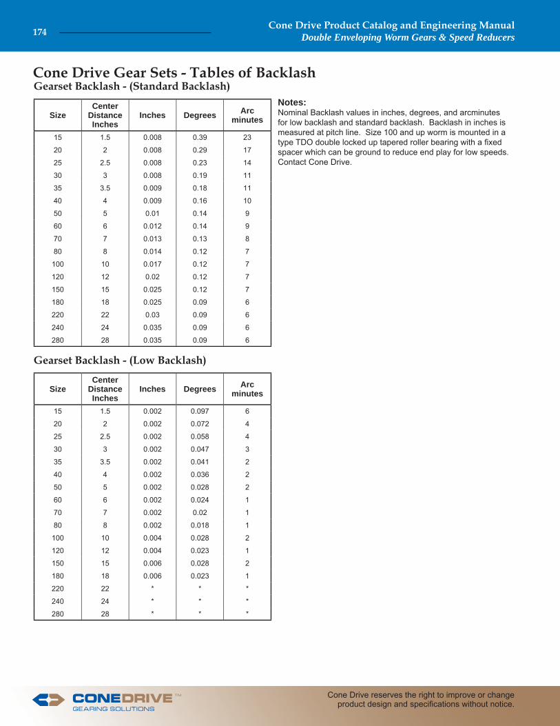
Cone Drive Gear Sets - Tables of BacklashGearset Backlash - (Standard Backlash)
Gearset Backlash - (Low Backlash)
Notes: Nominal Backlash values in inches, degrees, and arcminutes for low backlash and standard backlash. Backlash in inches is measured at pitch line. Size 100 and up worm is mounted in a type TDO double locked up tapered roller bearing with a fi xed spacer which can be ground to reduce end play for low speeds.Contact Cone Drive.
SizeCenter
DistanceInches
Inches Degrees Arcminutes
15 1.5 0.008 0.39 23
20 2 0.008 0.29 17
25 2.5 0.008 0.23 14
30 3 0.008 0.19 11
35 3.5 0.009 0.18 11
40 4 0.009 0.16 10
50 5 0.01 0.14 9
60 6 0.012 0.14 9
70 7 0.013 0.13 8
80 8 0.014 0.12 7
100 10 0.017 0.12 7
120 12 0.02 0.12 7
150 15 0.025 0.12 7
180 18 0.025 0.09 6
220 22 0.03 0.09 6
240 24 0.035 0.09 6
280 28 0.035 0.09 6
SizeCenter
DistanceInches
Inches Degrees Arcminutes
15 1.5 0.002 0.097 6
20 2 0.002 0.072 4
25 2.5 0.002 0.058 4
30 3 0.002 0.047 3
35 3.5 0.002 0.041 2
40 4 0.002 0.036 2
50 5 0.002 0.028 2
60 6 0.002 0.024 1
70 7 0.002 0.02 1
80 8 0.002 0.018 1
100 10 0.004 0.028 2
120 12 0.004 0.023 1
150 15 0.006 0.028 2
180 18 0.006 0.023 1
220 22 * * *
240 24 * * *
280 28 * * *
Cone Drive Product Catalog and Engineering ManualDouble Enveloping Worm Gears & Speed Reducers174
Cone Drive reserves the right to improve or change product design and specifi cations without notice.
TM
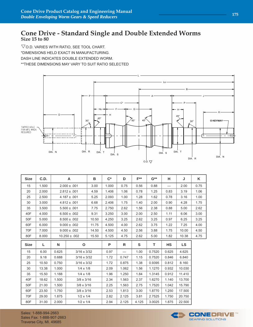
Cone Drive - Standard Single and Double Extended Worms
O.D. VARIES WITH RATIO, SEE TOOL CHART.*DIMENSIONS HELD EXACT IN MANUFACTURING.DASH LINE INDICATES DOUBLE EXTENDED WORM.**THESE DIMENSIONS MAY VARY TO SUIT RATIO SELECTED
L
Ls
B
A J
O KEYWAY
DK
P
C*
GFHs
H45°
30°
45°
H
P
DIA. NDIA. R
DIA. TDIA. S
O.D.
DIA. N DIA. R DIA. T
30°
DIA. S
45° 45°
Size C.D. A B C* D F** G** H J K
15 1.500 2.000 ± .001 3.00 1.000 0.75 0.56 0.88 — 2.00 0.75
20 2.000 2.812 ± .001 4.59 1.406 1.06 0.78 1.25 0.83 3.19 1.06
25 2.500 4.187 ± .001 5.25 2.093 1.00 1.28 1.62 0.78 3.16 1.00
30 3.000 4.812 ± .001 6.68 2.406 1.75 1.40 2.00 0.90 4.28 1.75
35 3.500 5.500 ± .001 7.75 2.750 2.62 1.56 2.38 0.88 5.00 2.62
40F 4.000 6.500 ± .002 9.31 3.250 3.00 2.00 2.50 1.11 6.06 3.00
50F 5.000 8.500 ± .002 10.50 4.250 3.25 2.62 3.25 0.97 6.25 3.25
60F 6.000 9.000 ± .002 11.75 4.500 4.00 2.62 3.75 1.22 7.25 4.00
70F 7.000 9.000 ± .002 14.50 4.500 4.50 2.56 3.88 1.75 10.00 4.50
80F 8.000 10.250 ± .002 15.50 5.125 4.75 2.62 5.00 1.82 10.38 4.75
Size L N O P R S T HS LS
15 6.00 0.625 3/16 x 3/32 0.97 — 1.00 0.7520 0.625 4.625
20 9.18 0.688 3/16 x 3/32 1.72 0.747 1.15 0.7520 0.846 6.840
25 10.50 0.750 3/16 x 3/32 1.72 0.875 1.38 0.9395 0.812 8.160
30 13.38 1.000 1/4 x 1/8 2.09 1.062 1.56 1.1270 0.932 10.030
35 15.50 1.188 1/4 x 1/8 1.96 1.250 1.84 1.3145 0.912 11.410
40F 18.62 1.500 3/8 x 3/16 2.34 1.563 2.37 1.6270 1.140 13.700
50F 21.00 1.500 3/8 x 3/16 2.25 1.563 2.75 1.7520 1.042 15.790
60F 23.50 1.750 3/8 x 3/16 2.53 1.813 3.00 1.8770 1.250 17.500
70F 29.00 1.875 1/2 x 1/4 2.82 2.125 3.81 2.7525 1.750 20.750
80F 31.00 2.000 1/2 x 1/4 2.94 2.125 4.125 3.0025 1.875 22.500
Size 15 to 80
TM
Cone Drive Product Catalog and Engineering ManualDouble Enveloping Worm Gears & Speed Reducers 175
Sales: 1-888-994-2663Sales Fax: 1-888-907-2663Traverse City, MI. 49685
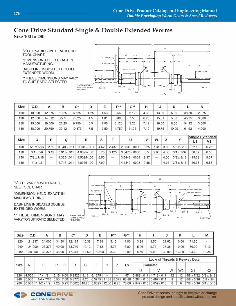
Cone Drive Standard Single & Double Extended Worms
L
Ls
B
A
O KEYWAYD
K
C*
GF
H 45° 45°
P
DIA. NDIA. U
DIA. T
DIA. X
O.D.
DIA. N DIA. R
DIA. T DIA. S
TAPPED HOLEFOR MFG. WHENREQUIRED
EVs
DIA. Q
V
W
Y KEYWAY
I2 THREAD
O.D. VARIES WITH RATIO, SEE TOOL CHART.*DIMENSIONS HELD EXACT IN MANUFACTURING.DASH LINE INDICATES DOUBLE EXTENDED WORM.**THESE DIMENSIONS MAY VARY TO SUIT RATIO SELECTED
JD
E
L
Ls
B
A
Y
O KEYWAY
I K
M C*
GF
DIA. Z
45° 45° H
P
DIA. NDIA. ZDIA. R
DIA. Q
O.D.DIA. N
DIA. UDIA. T DIA. S
W1 THREAD
X2 KEYWAYX1 KEYWAY
W2 THREAD
DIA. VTAPPED HOLEFOR MFG. WHENREQUIRED
O.D. VARIES WITH RATIO, SEE TOOL CHART.
*DIMENSION HELD EXACT IN MANUFACTURING.
DASH LINE INDICATES DOUBLE EXTENDED WORM.
**THESE DIMENSIONS MAY VARY TO SUIT RATIO SELECTED
Size C.D. A B C* D E F** G** H J K L N
100 10.000 12.875 19.25 6.625 4.25 1.53 3.560 6.12 4.38 13.00 5.00 38.50 2.375
120 12.000 14.812 22.5 7.625 4.5 1.81 3.880 7.50 6.25 15.31 5.88 45.75 3.000
150 15.000 19.500 26.25 9.750 5.5 2.00 5.120 9.25 7.12 16.50 8.50 54.12 3.500
180 18.000 20.750 30.12 10.375 7.5 2.50 4.750 11.25 7.12 19.75 10.00 61.62 4.000
Size C.D. A B C* D E F** G** H I J K L M
220 21.837 24.000 34.50 12.125 10.38 7.38 5.15 14.00 3.88 9.50 22.62 10.00 71.50 -
240 24.000 26.375 40.00 13.750 10.12 7.12 5.75 16.00 5.06 9.75 27.38 10.00 80.00 15.12
280 28.000 33.375 46.00 17.375 13.50 10.00 8.38 18.00 5.50 9.00 30.00 13.00 94.00 18.25
Size O P Q R S T U V W X YSingle Extended
LS VS100 5/8 x 5/16 2.59 3.340 - .011 3.349- .001 4.62 2.437 2.9536- .0006 6.25 7.31 3.50 5/8 x 3/16 32.12 6.25
120 3/4 x 3/8 3.12 3.918- .011 4.0025- .001 5.75 3.125 3.3475- .0008 8.5 9.68 4.00 3/4 x 7/32 38.62 8.50
150 7/8 x 7/16 — 4.325- .011 4.5025- .001 6.50 — 3.5443- .0008 9.37 — 4.00 3/8 x 3/16 45.38 9.37
180 1" x 1/2 — 4.716- .011 5.0025- .001 7.00 — 4.1349- .0008 9.88 — 4.75 3/8 x 3/16 50.38 9.88
Size N O P Q R S T Y Z LsLocknut Threads & Keyway Data
DiameterU V W1 W2 X1 X2
220 4.500 1" x 1/2 5.15 6.00 5.2525 8.12 6.1275 – – 57 5.888 -.011 4.716 -.011 12 12 5/8 x 7/32 3/8 x 3/16240 5.000 1 1/4 x 7/16 6.50 7.00 5.8775 8.25 6.3775 11.38 5.375 63.88 6.284 -.015 5.497 -.011 8 12 5/8 x 5/16 5/8 x 1/4280 6.000 1 1/2 x 1/2 7.25 8.25 7.0025 10.25 8.0025 12.00 6.25 76.88 7.847 -.015 6.659 -.015 8 8 7/8 x 5/16 3/4 x 5/16
Size 100 to 280
Cone Drive Product Catalog and Engineering ManualDouble Enveloping Worm Gears & Speed Reducers176
Cone Drive reserves the right to improve or change product design and specifi cations without notice.
TM
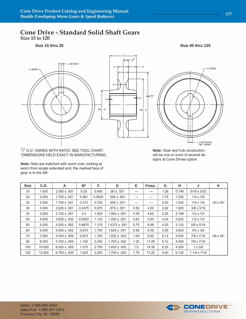
Size 15 thru 35 Size 40 thru 120
Note: Gear and hub constuction will be one or more of several de-signs at Cone Drives option.
O.D. VARIES WITH RATIO, SEE TOOL CHART.*DIMENSIONS HELD EXACT IN MANUFACTURING.
Note: Sets are matched with worm over, looking at worm from single extended end, the marked face of gear is to the left.
O.D.
DIA. F
KK
DIA. G
A
B
C DH BOREH BORE
J KEYWAY
E
J 2 KEYWAYS 180 APART
*
Size C.D. A B* C D E Fmax. G H J K15 1.500 2.000 ± .001 0.20 0.400 .80 ± .001 — — 1.28 0.748 3/16 x 3/32
.03 x 45°
20 2.000 1.750 ± .001 0.281 0.5625 .594 ± .001 — — 1.75 1.250 1/4 x 1/8
25 2.500 1.750 ± .001 0.375 0.750 .500 ± .001 — — 2.00 1.250 1/4 x 1/8
30 3.000 2.625 ± .001 0.4375 0.875 .875 ± .001 0.50 4.00 2.62 1.625 3/8 x 3/16
35 3.500 3.125 ± .001 0.5 1.000 1.062 ± .001 0.50 4.62 3.25 2.188 1/2 x 1/4
40 4.000 3.625 ± .002 0.5625 1.125 1.250 ± .001 0.62 5.50 4.00 2.625 1/2 x 1/4
.06 x 45°
50 5.000 4.250 ± .002 0.6875 1.375 1.4375 ± .001 0.75 6.88 4.50 3.125 5/8 x 5/16
60 6.000 5.000 ± .002 0.875 1.750 1.625 ± .001 0.88 8.38 5.50 3.625 3/4 x 3/8
70 7.000 5.000 ± .005 0.875 1.750 1.625 ± .002 1.00 9.62 6.12 4.000 7/8 x 7/16
80 8.000 5.750 ± .005 1.125 2.250 1.750 ± .002 1.25 11.09 6.12 4.000 7/8 x 7/16
100 10.000 6.000 ± .005 1.375 2.750 1.625 ± .002 1.5 14.38 6.25 4.250 1 x 3/8
120 12.000 6.750 ± .005 1.625 3.250 1.750 ± .002 1.75 17.25 9.00 6.125 1 1/4 x 7/16
Size 15 to 120 Cone Drive - Standard Solid Shaft Gears
TM
Cone Drive Product Catalog and Engineering ManualDouble Enveloping Worm Gears & Speed Reducers 177
Sales: 1-888-994-2663Sales Fax: 1-888-907-2663Traverse City, MI. 49685
H
J
K
P
X B.C.
DIA. D
O.D.
E BORE
F 2 KEYWAYS 180° APART
R
M
DIA. A
DIA. O
BOLT HOLESARE REAMEDFOR TIGHT FIT
BODY BOUNDBOLTS
*
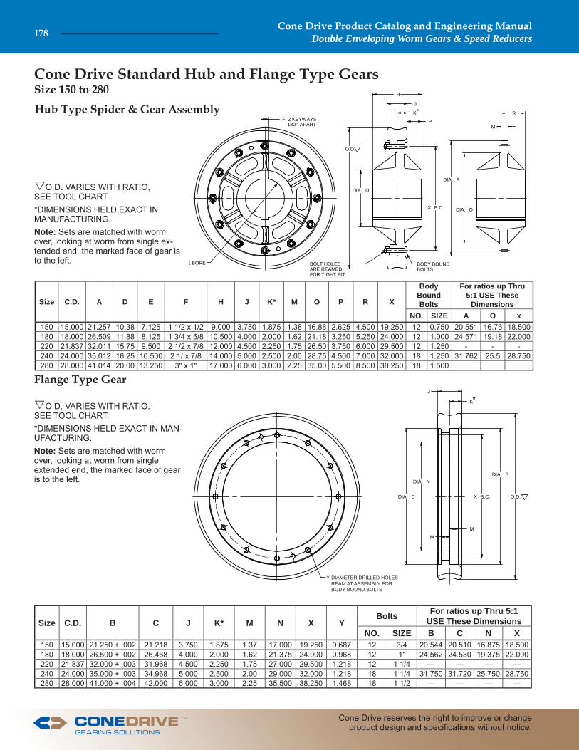
O.D. VARIES WITH RATIO, SEE TOOL CHART.*DIMENSIONS HELD EXACT IN MANUFACTURING.Note: Sets are matched with worm over, looking at worm from single ex-tended end, the marked face of gear is to the left.
Hub Type Spider & Gear Assembly
Flange Type Gear J
K
O.D.
DIA. B
X B.C.
MM
DIA. N
DIA. C
*
Y DIAMETER DRILLED HOLES REAM AT ASSEMBLY FOR BODY BOUND BOLTS
O.D. VARIES WITH RATIO, SEE TOOL CHART.*DIMENSIONS HELD EXACT IN MAN-UFACTURING.Note: Sets are matched with worm over, looking at worm from single extended end, the marked face of gear is to the left.
Size C.D. A D E F H J K* M O P R X
Body Bound Bolts
For ratios up Thru 5:1 USE These
DimensionsNO. SIZE A O x
150 15.000 21.257 10.38 7.125 1 1/2 x 1/2 9.000 3.750 1.875 1.38 16.88 2.625 4.500 19.250 12 0.750 20.551 16.75 18.500180 18.000 26.509 11.88 8.125 1 3/4 x 5/8 10.500 4.000 2.000 1.62 21.18 3.250 5.250 24.000 12 1.000 24.571 19.18 22.000220 21.837 32.011 15.75 9.500 2 1/2 x 7/8 12.000 4.500 2.250 1.75 26.50 3.750 6.000 29.500 12 1.250 - - -240 24.000 35.012 16.25 10.500 2 1/ x 7/8 14.000 5.000 2.500 2.00 28.75 4.500 7.000 32.000 18 1.250 31.762 25.5 28.750280 28.000 41.014 20.00 13.250 3" x 1" 17.000 6.000 3.000 2.25 35.00 5.500 8.500 38.250 18 1.500
Size C.D. B C J K* M N X YBolts For ratios up Thru 5:1
USE These DimensionsNO. SIZE B C N X
150 15.000 21.250 + .002 21.218 3.750 1.875 1.37 17.000 19.250 0.687 12 3/4 20.544 20.510 16.875 18.500180 18.000 26.500 + .002 26.468 4.000 2.000 1.62 21.375 24.000 0.968 12 1" 24.562 24.530 19.375 22.000220 21.837 32.000 + .003 31.968 4.500 2.250 1.75 27.000 29.500 1.218 12 1 1/4 — — — —240 24.000 35.000 + .003 34.968 5.000 2.500 2.00 29.000 32.000 1.218 18 1 1/4 31.750 31.720 25.750 28.750280 28.000 41.000 + .004 42.000 6.000 3.000 2.25 35.500 38.250 1.468 18 1 1/2 — — — —
Size 150 to 280 Cone Drive Standard Hub and Flange Type Gears
Cone Drive Product Catalog and Engineering ManualDouble Enveloping Worm Gears & Speed Reducers178
Cone Drive reserves the right to improve or change product design and specifi cations without notice.
TM
J
K
O.D. DIA. L
J
K
O.D.
DIA. B
X B.C.
MM
DIA. N
DIA. C
**
DIAMETER DRILLED HOLES REAM AT ASSEMBLY FOR BODY BOUND BOLTS
Y
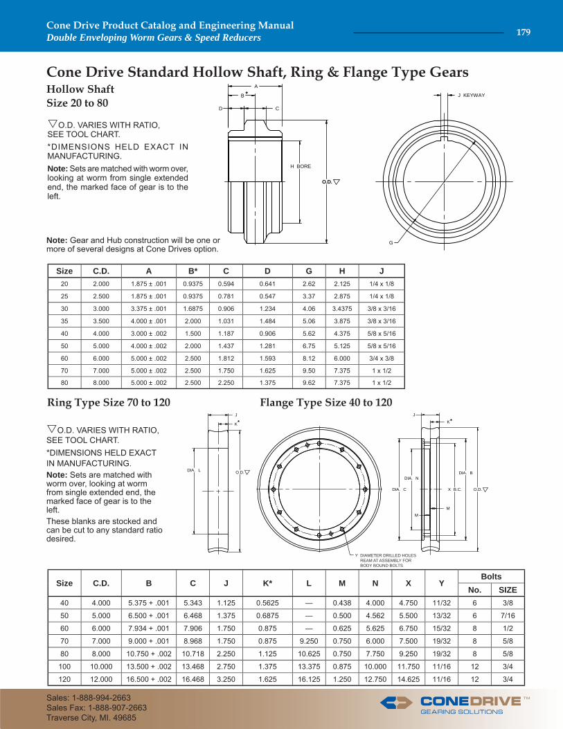
Ring Type Size 70 to 120 Flange Type Size 40 to 120
O.D. VARIES WITH RATIO, SEE TOOL CHART.*DIMENSIONS HELD EXACT IN MANUFACTURING.Note: Sets are matched with worm over, looking at worm from single extended end, the marked face of gear is to the left.
Cone Drive Standard Hollow Shaft, Ring & Flange Type GearsHollow Shaft Size 20 to 80
O.D.
H BORE
A
B
CD
J KEYWAY
G
*
Note: Gear and Hub construction will be one or more of several designs at Cone Drives option.
O.D. VARIES WITH RATIO, SEE TOOL CHART.*DIMENSIONS HELD EXACT IN MANUFACTURING.Note: Sets are matched with worm over, looking at worm from single extended end, the marked face of gear is to the left.These blanks are stocked and can be cut to any standard ratio desired.
Size C.D. A B* C D G H J20 2.000 1.875 ± .001 0.9375 0.594 0.641 2.62 2.125 1/4 x 1/8
25 2.500 1.875 ± .001 0.9375 0.781 0.547 3.37 2.875 1/4 x 1/8
30 3.000 3.375 ± .001 1.6875 0.906 1.234 4.06 3.4375 3/8 x 3/16
35 3.500 4.000 ± .001 2.000 1.031 1.484 5.06 3.875 3/8 x 3/16
40 4.000 3.000 ± .002 1.500 1.187 0.906 5.62 4.375 5/8 x 5/16
50 5.000 4.000 ± .002 2.000 1.437 1.281 6.75 5.125 5/8 x 5/16
60 6.000 5.000 ± .002 2.500 1.812 1.593 8.12 6.000 3/4 x 3/8
70 7.000 5.000 ± .002 2.500 1.750 1.625 9.50 7.375 1 x 1/2
80 8.000 5.000 ± .002 2.500 2.250 1.375 9.62 7.375 1 x 1/2
Size C.D. B C J K* L M N X YBolts
No. SIZE40 4.000 5.375 + .001 5.343 1.125 0.5625 — 0.438 4.000 4.750 11/32 6 3/8
50 5.000 6.500 + .001 6.468 1.375 0.6875 — 0.500 4.562 5.500 13/32 6 7/16
60 6.000 7.934 + .001 7.906 1.750 0.875 — 0.625 5.625 6.750 15/32 8 1/2
70 7.000 9.000 + .001 8.968 1.750 0.875 9.250 0.750 6.000 7.500 19/32 8 5/8
80 8.000 10.750 + .002 10.718 2.250 1.125 10.625 0.750 7.750 9.250 19/32 8 5/8
100 10.000 13.500 + .002 13.468 2.750 1.375 13.375 0.875 10.000 11.750 11/16 12 3/4
120 12.000 16.500 + .002 16.468 3.250 1.625 16.125 1.250 12.750 14.625 11/16 12 3/4
TM
Cone Drive Product Catalog and Engineering ManualDouble Enveloping Worm Gears & Speed Reducers 179
Sales: 1-888-994-2663Sales Fax: 1-888-907-2663Traverse City, MI. 49685
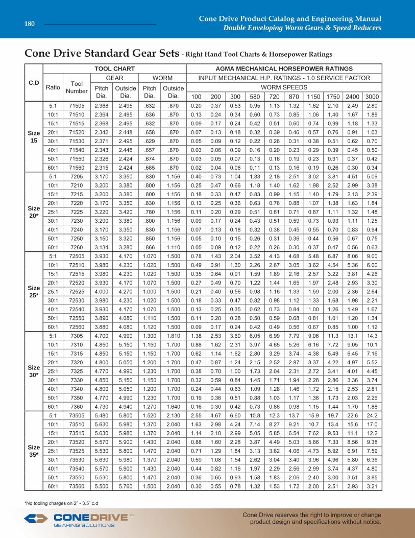
Cone Drive Standard Gear Sets
C.D
TOOL CHART AGMA MECHANICAL HORSEPOWER RATINGS
Ratio Tool Number
GEAR WORM INPUT MECHANICAL H.P. RATINGS - 1.0 SERVICE FACTOR
Pitch Dia.
Outside Dia.
Pitch Dia.
Outside Dia.
WORM SPEEDS100 200 300 580 720 870 1150 1750 2400 3000
Size 15
5:1 71505 2.368 2.495 .632 .870 0.20 0.37 0.53 0.95 1.13 1.32 1.62 2.10 2.49 2.8010:1 71510 2.364 2.495 .636 .870 0.13 0.24 0.34 0.60 0.73 0.85 1.06 1.40 1.67 1.8915:1 71515 2.368 2.495 .632 .870 0.09 0.17 0.24 0.42 0.51 0.60 0.74 0.99 1.18 1.3320:1 71520 2.342 2.448 .658 .870 0.07 0.13 0.18 0.32 0.39 0.46 0.57 0.76 0.91 1.0330:1 71530 2.371 2.495 .629 .870 0.05 0.09 0.12 0.22 0.26 0.31 0.38 0.51 0.62 0.7040:1 71540 2.343 2.448 .657 .870 0.03 0.06 0.09 0.16 0.20 0.23 0.29 0.39 0.45 0.5050:1 71550 2.326 2.424 .674 .870 0.03 0.05 0.07 0.13 0.16 0.19 0.23 0.31 0.37 0.4260:1 71560 2.315 2.424 .685 .870 0.02 0.04 0.06 0.11 0.13 0.16 0.19 0.26 0.30 0.34
Size 20*
5:1 7205 3.170 3.350 .830 1.156 0.40 0.73 1.04 1.83 2.18 2.51 3.02 3.81 4.51 5.0910:1 7210 3.200 3.380 .800 1.156 0.25 0.47 0.66 1.18 1.40 1.62 1.98 2.52 2.99 3.3815:1 7215 3.200 3.380 .800 1.156 0.18 0.33 0.47 0.83 0.99 1.15 1.40 1.79 2.13 2.3920:1 7220 3.170 3.350 .830 1.156 0.13 0.25 0.36 0.63 0.76 0.88 1.07 1.38 1.63 1.8425:1 7225 3.220 3.420 .780 1.156 0.11 0.20 0.29 0.51 0.61 0.71 0.87 1.11 1.32 1.4830:1 7230 3.200 3.380 .800 1.156 0.09 0.17 0.24 0.43 0.51 0.59 0.73 0.93 1.11 1.2540:1 7240 3.170 3.350 .830 1.156 0.07 0.13 0.18 0.32 0.38 0.45 0.55 0.70 0.83 0.9450:1 7250 3.150 3.320 .850 1.156 0.05 0.10 0.15 0.26 0.31 0.36 0.44 0.56 0.67 0.7560:1 7260 3.134 3.280 .866 1.110 0.05 0.09 0.12 0.22 0.26 0.30 0.37 0.47 0.56 0.63
Size25*
5:1 72505 3.930 4.170 1.070 1.500 0.78 1.43 2.04 3.52 4.13 4.68 5.48 6.87 8.06 9.0010:1 72510 3.980 4.230 1.020 1.500 0.49 0.91 1.30 2.26 2.67 3.05 3.62 4.54 5.36 6.0015:1 72515 3.980 4.230 1.020 1.500 0.35 0.64 0.91 1.59 1.89 2.16 2.57 3.22 3.81 4.2620:1 72520 3.930 4.170 1.070 1.500 0.27 0.49 0.70 1.22 1.44 1.65 1.97 2.48 2.93 3.3025:1 72525 4.000 4.270 1.000 1.500 0.21 0.40 0.56 0.98 1.16 1.33 1.59 2.00 2.36 2.6430:1 72530 3.980 4.230 1.020 1.500 0.18 0.33 0.47 0.82 0.98 1.12 1.33 1.68 1.98 2.2140:1 72540 3.930 4.170 1.070 1.500 0.13 0.25 0.35 0.62 0.73 0.84 1.00 1.26 1.49 1.6750:1 72550 3.890 4.080 1.110 1.500 0.11 0.20 0.28 0.50 0.59 0.68 0.81 1.01 1.20 1.3460:1 72560 3.880 4.080 1.120 1.500 0.09 0.17 0.24 0.42 0.49 0.56 0.67 0.85 1.00 1.12
Size30*
5:1 7305 4.700 4.990 1.300 1.810 1.38 2.53 3.60 6.05 6.99 7.79 9.06 11.3 13.1 14.310:1 7310 4.850 5.150 1.150 1.700 0.88 1.62 2.31 3.97 4.65 5.26 6.16 7.72 9.05 10.115:1 7315 4.850 5.150 1.150 1.700 0.62 1.14 1.62 2.80 3.29 3.74 4.38 5.49 6.45 7.1620:1 7320 4.800 5.050 1.200 1.700 0.47 0.87 1.24 2.15 2.52 2.87 3.37 4.22 4.97 5.5225:1 7325 4.770 4.990 1.230 1.700 0.38 0.70 1.00 1.73 2.04 2.31 2.72 3.41 4.01 4.4530:1 7330 4.850 5.150 1.150 1.700 0.32 0.59 0.84 1.45 1.71 1.94 2.28 2.86 3.36 3.7440:1 7340 4.800 5.050 1.200 1.700 0.24 0.44 0.63 1.09 1.28 1.46 1.72 2.15 2.53 2.8150:1 7350 4.770 4.990 1.230 1.700 0.19 0.36 0.51 0.88 1.03 1.17 1.38 1.73 2.03 2.2660:1 7360 4.730 4.940 1.270 1.640 0.16 0.30 0.42 0.73 0.86 0.98 1.15 1.44 1.70 1.88
Size35*
5:1 73505 5.480 5.800 1.520 2.130 2.55 4.67 6.60 10.8 12.3 13.7 15.9 19.7 22.6 24.210:1 73510 5.630 5.980 1.370 2.040 1.63 2.98 4.24 7.14 8.27 9.21 10.7 13.4 15.6 17.015:1 73515 5.630 5.980 1.370 2.040 1.14 2.10 2.99 5.05 5.85 6.54 7.62 9.53 11.1 12.220:1 73520 5.570 5.900 1.430 2.040 0.88 1.60 2.28 3.87 4.49 5.03 5.86 7.33 8.56 9.3825:1 73525 5.530 5.800 1.470 2.040 0.71 1.29 1.84 3.13 3.62 4.06 4.73 5.92 6.91 7.5930:1 73530 5.630 5.980 1.370 2.040 0.59 1.08 1.54 2.62 3.04 3.40 3.96 4.96 5.80 6.3640:1 73540 5.570 5.900 1.430 2.040 0.44 0.82 1.16 1.97 2.29 2.56 2.99 3.74 4.37 4.8050:1 73550 5.530 5.800 1.470 2.040 0.36 0.65 0.93 1.58 1.83 2.06 2.40 3.00 3.51 3.8560:1 73560 5.500 5.760 1.500 2.040 0.30 0.55 0.78 1.32 1.53 1.72 2.00 2.51 2.93 3.21
*No tooling charges on 2” - 3.5” c.d
- Right Hand Tool Charts & Horsepower Ratings
Cone Drive Product Catalog and Engineering ManualDouble Enveloping Worm Gears & Speed Reducers180
Cone Drive reserves the right to improve or change product design and specifi cations without notice.
TM
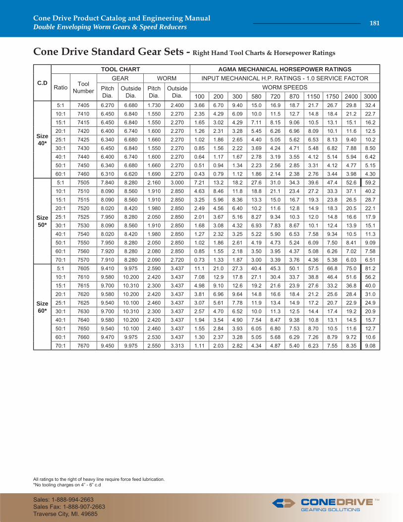
Cone Drive Standard Gear Sets - Right Hand Tool Charts & Horsepower Ratings
C.D
TOOL CHART AGMA MECHANICAL HORSEPOWER RATINGS
Ratio Tool Number
GEAR WORM INPUT MECHANICAL H.P. RATINGS - 1.0 SERVICE FACTOR
Pitch Dia.
Outside Dia.
Pitch Dia.
Outside Dia.
WORM SPEEDS100 200 300 580 720 870 1150 1750 2400 3000
Size 40*
5:1 7405 6.270 6.680 1.730 2.400 3.66 6.70 9.40 15.0 16.9 18.7 21.7 26.7 29.8 32.410:1 7410 6.450 6.840 1.550 2.270 2.35 4.29 6.09 10.0 11.5 12.7 14.8 18.4 21.2 22.715:1 7415 6.450 6.840 1.550 2.270 1.65 3.02 4.29 7.11 8.15 9.06 10.5 13.1 15.1 16.220:1 7420 6.400 6.740 1.600 2.270 1.26 2.31 3.28 5.45 6.26 6.96 8.09 10.1 11.6 12.525:1 7425 6.340 6.680 1.660 2.270 1.02 1.86 2.65 4.40 5.05 5.62 6.53 8.13 9.40 10.230:1 7430 6.450 6.840 1.550 2.270 0.85 1.56 2.22 3.69 4.24 4.71 5.48 6.82 7.88 8.5040:1 7440 6.400 6.740 1.600 2.270 0.64 1.17 1.67 2.78 3.19 3.55 4.12 5.14 5.94 6.4250:1 7450 6.340 6.680 1.660 2.270 0.51 0.94 1.34 2.23 2.56 2.85 3.31 4.12 4.77 5.1560:1 7460 6.310 6.620 1.690 2.270 0.43 0.79 1.12 1.86 2.14 2.38 2.76 3.44 3.98 4.30
Size 50*
5:1 7505 7.840 8.280 2.160 3.000 7.21 13.2 18.2 27.6 31.0 34.3 39.6 47.4 52.6 59.210:1 7510 8.090 8.560 1.910 2.850 4.63 8.46 11.8 18.8 21.1 23.4 27.2 33.3 37.1 40.215:1 7515 8.090 8.560 1.910 2.850 3.25 5.96 8.36 13.3 15.0 16.7 19.3 23.8 26.5 28.720:1 7520 8.020 8.420 1.980 2.850 2.49 4.56 6.40 10.2 11.6 12.8 14.9 18.3 20.5 22.125:1 7525 7.950 8.280 2.050 2.850 2.01 3.67 5.16 8.27 9.34 10.3 12.0 14.8 16.6 17.930:1 7530 8.090 8.560 1.910 2.850 1.68 3.08 4.32 6.93 7.83 8.67 10.1 12.4 13.9 15.140:1 7540 8.020 8.420 1.980 2.850 1.27 2.32 3.25 5.22 5.90 6.53 7.58 9.34 10.5 11.350:1 7550 7.950 8.280 2.050 2.850 1.02 1.86 2.61 4.19 4.73 5.24 6.09 7.50 8.41 9.0960:1 7560 7.920 8.280 2.080 2.850 0.85 1.55 2.18 3.50 3.95 4.37 5.08 6.26 7.02 7.5870:1 7570 7.910 8.280 2.090 2.720 0.73 1.33 1.87 3.00 3.39 3.76 4.36 5.38 6.03 6.51
Size60*
5:1 7605 9.410 9.975 2.590 3.437 11.1 21.0 27.3 40.4 45.3 50.1 57.5 66.8 75.0 81.210:1 7610 9.580 10.200 2.420 3.437 7.08 12.9 17.8 27.1 30.4 33.7 38.8 46.4 51.6 56.215:1 7615 9.700 10.310 2.300 3.437 4.98 9.10 12.6 19.2 21.6 23.9 27.6 33.2 36.8 40.020:1 7620 9.580 10.200 2.420 3.437 3.81 6.96 9.64 14.8 16.6 18.4 21.2 25.6 28.4 31.025:1 7625 9.540 10.100 2.460 3.437 3.07 5.61 7.78 11.9 13.4 14.9 17.2 20.7 22.9 24.930:1 7630 9.700 10.310 2.300 3.437 2.57 4.70 6.52 10.0 11.3 12.5 14.4 17.4 19.2 20.940:1 7640 9.580 10.200 2.420 3.437 1.94 3.54 4.90 7.54 8.47 9.38 10.8 13.1 14.5 15.750:1 7650 9.540 10.100 2.460 3.437 1.55 2.84 3.93 6.05 6.80 7.53 8.70 10.5 11.6 12.760:1 7660 9.470 9.975 2.530 3.437 1.30 2.37 3.28 5.05 5.68 6.29 7.26 8.79 9.72 10.670:1 7670 9.450 9.975 2.550 3.313 1.11 2.03 2.82 4.34 4.87 5.40 6.23 7.55 8.35 9.08
All ratings to the right of heavy line require force feed lubrication.*No tooling charges on 4” - 6” c.d
TM
Cone Drive Product Catalog and Engineering ManualDouble Enveloping Worm Gears & Speed Reducers 181
Sales: 1-888-994-2663Sales Fax: 1-888-907-2663Traverse City, MI. 49685
Cone Drive Standard Gear Sets - Right Hand Tool Charts & Horsepower Ratings
C.D
TOOL CHART AGMA MECHANICAL HORSEPOWER RATINGS
Ratio Tool Number
GEAR WORM INPUT MECHANICAL H.P. RATINGS - 1.0 SERVICE FACTOR
Pitch Dia.
Outside Dia.
Pitch Dia.
Outside Dia.
WORM SPEEDS100 200 300 580 720 870 1150 1750 2400 3000
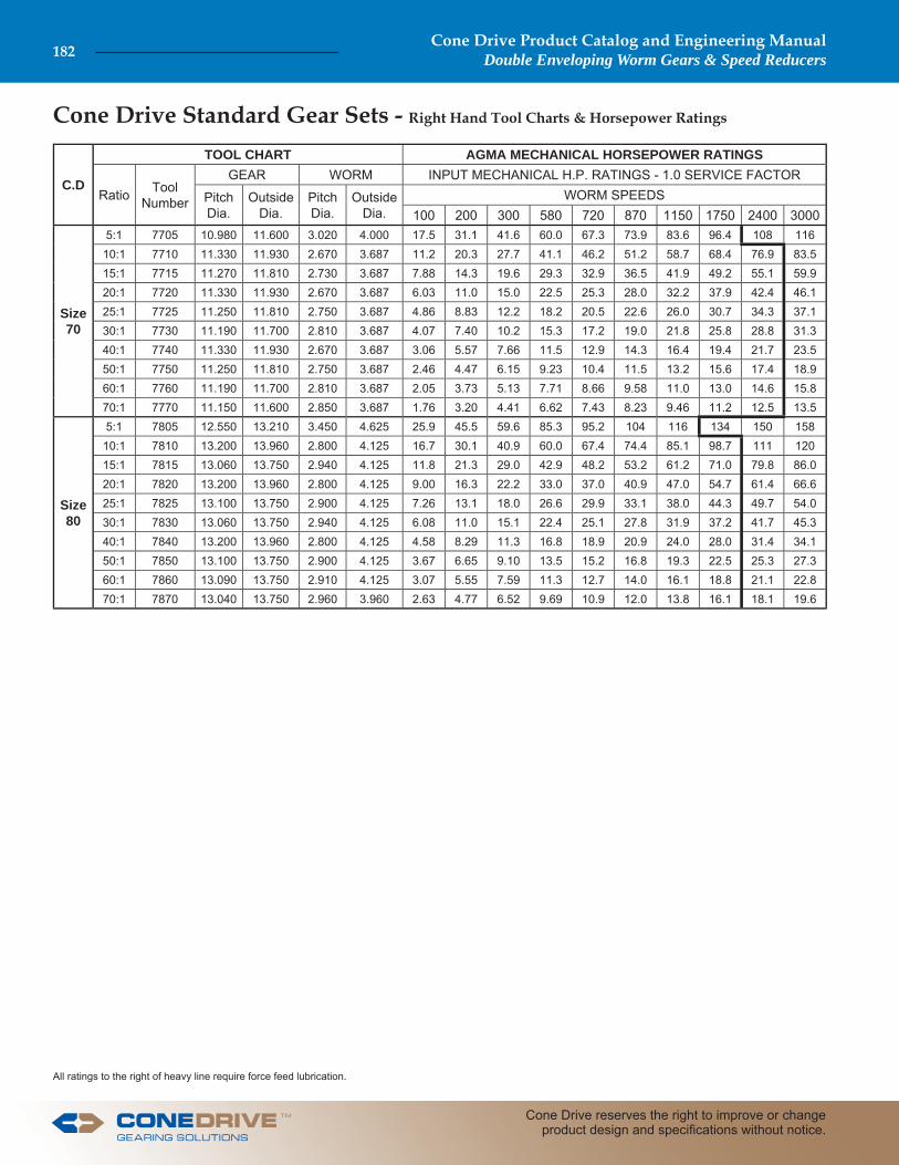
Size 70
5:1 7705 10.980 11.600 3.020 4.000 17.5 31.1 41.6 60.0 67.3 73.9 83.6 96.4 108 11610:1 7710 11.330 11.930 2.670 3.687 11.2 20.3 27.7 41.1 46.2 51.2 58.7 68.4 76.9 83.515:1 7715 11.270 11.810 2.730 3.687 7.88 14.3 19.6 29.3 32.9 36.5 41.9 49.2 55.1 59.920:1 7720 11.330 11.930 2.670 3.687 6.03 11.0 15.0 22.5 25.3 28.0 32.2 37.9 42.4 46.125:1 7725 11.250 11.810 2.750 3.687 4.86 8.83 12.2 18.2 20.5 22.6 26.0 30.7 34.3 37.130:1 7730 11.190 11.700 2.810 3.687 4.07 7.40 10.2 15.3 17.2 19.0 21.8 25.8 28.8 31.340:1 7740 11.330 11.930 2.670 3.687 3.06 5.57 7.66 11.5 12.9 14.3 16.4 19.4 21.7 23.550:1 7750 11.250 11.810 2.750 3.687 2.46 4.47 6.15 9.23 10.4 11.5 13.2 15.6 17.4 18.960:1 7760 11.190 11.700 2.810 3.687 2.05 3.73 5.13 7.71 8.66 9.58 11.0 13.0 14.6 15.870:1 7770 11.150 11.600 2.850 3.687 1.76 3.20 4.41 6.62 7.43 8.23 9.46 11.2 12.5 13.5
Size80
5:1 7805 12.550 13.210 3.450 4.625 25.9 45.5 59.6 85.3 95.2 104 116 134 150 15810:1 7810 13.200 13.960 2.800 4.125 16.7 30.1 40.9 60.0 67.4 74.4 85.1 98.7 111 12015:1 7815 13.060 13.750 2.940 4.125 11.8 21.3 29.0 42.9 48.2 53.2 61.2 71.0 79.8 86.020:1 7820 13.200 13.960 2.800 4.125 9.00 16.3 22.2 33.0 37.0 40.9 47.0 54.7 61.4 66.625:1 7825 13.100 13.750 2.900 4.125 7.26 13.1 18.0 26.6 29.9 33.1 38.0 44.3 49.7 54.030:1 7830 13.060 13.750 2.940 4.125 6.08 11.0 15.1 22.4 25.1 27.8 31.9 37.2 41.7 45.340:1 7840 13.200 13.960 2.800 4.125 4.58 8.29 11.3 16.8 18.9 20.9 24.0 28.0 31.4 34.150:1 7850 13.100 13.750 2.900 4.125 3.67 6.65 9.10 13.5 15.2 16.8 19.3 22.5 25.3 27.360:1 7860 13.090 13.750 2.910 4.125 3.07 5.55 7.59 11.3 12.7 14.0 16.1 18.8 21.1 22.870:1 7870 13.040 13.750 2.960 3.960 2.63 4.77 6.52 9.69 10.9 12.0 13.8 16.1 18.1 19.6
All ratings to the right of heavy line require force feed lubrication.
Cone Drive Product Catalog and Engineering ManualDouble Enveloping Worm Gears & Speed Reducers182
Cone Drive reserves the right to improve or change product design and specifi cations without notice.
TM

Cone Drive Standard Gear Sets - Right Hand Tool Charts & Horsepower Ratings
C.D
TOOL CHART AGMA MECHANICAL HORSEPOWER RATINGS
Ratio Tool Number
GEAR WORM INPUT MECHANICAL H.P. RATINGS - 1.0 SERVICE FACTOR
Pitch Dia.
Outside Dia.
Pitch Dia.
Outside Dia.
WORM SPEEDS100 200 300 580 720 870 1150 1750 2400
Size 100
5:1 8005 15.700 16.500 4.300 5.600 48.5 82.3 105 148 164 178 194 226 24510:1 8010 16.400 17.250 3.600 5.062 31.4 55.5 73.2 105 117 129 144 166 18615:1 8015 16.400 17.250 3.600 5.062 22.1 39.2 52.1 74.8 83.7 91.9 104 119 13320:1 8020 16.450 17.350 3.550 5.062 16.9 30.1 40.0 57.5 64.4 70.7 79.8 91.8 10325:1 8025 16.400 17.250 3.600 5.062 13.6 24.3 32.3 46.5 52.1 57.2 64.6 74.3 83.330:1 8030 16.300 17.050 3.700 5.062 11.4 20.3 27.1 39.0 43.7 48.0 54.2 62.4 70.040:1 8040 16.450 17.250 3.550 5.062 8.60 15.3 20.4 29.4 32.9 36.1 40.9 47.0 52.750:1 8050 16.400 17.250 3.600 5.062 6.90 12.3 16.4 23.6 26.4 29.0 32.8 37.8 42.360:1 8060 16.330 17.050 3.670 5.062 5.76 10.3 13.7 19.7 22.1 24.2 27.4 31.6 35.470:1 8070 16.280 17.050 3.720 5.000 4.94 8.80 11.7 16.9 18.9 20.8 23.5 27.1 30.4
Size 120
5:1 8205 18.820 19.750 5.180 6.750 81.3 134 167 235 257 271 300 346 36610:1 8210 19.700 20.600 4.300 6.187 53.2 91.8 118 167 186 202 221 258 28315:1 8215 19.700 20.600 4.300 6.187 37.5 65.0 83.9 119 133 145 159 185 20520:1 8220 19.840 20.880 4.160 6.187 28.7 49.8 64.4 91.9 102 111 122 143 15825:1 8225 19.700 20.600 4.300 6.187 23.1 40.2 52.1 74.3 82.7 90.1 99.1 115 12830:1 8230 19.610 20.420 4.390 6.187 19.4 33.7 43.7 62.4 69.4 75.7 83.2 97.0 10840:1 8240 19.840 20.880 4.160 6.187 14.6 25.4 32.9 47.0 52.2 57.0 62.7 73.0 81.150:1 8250 19.700 20.600 4.300 6.187 11.7 20.4 26.4 37.7 41.9 45.8 50.4 58.7 65.260:1 8260 19.640 20.420 4.360 6.187 9.77 17.0 22.1 31.5 35.0 38.2 42.1 49.0 54.470:1 8270 19.590 20.420 4.410 6.000 8.39 14.6 18.9 27.0 30.1 32.8 36.1 42.1 46.7
Size150
5:1 8505 23.600 24.750 6.400 8.625 149 233 290 396 423 453 501 554 60110:1 8510 24.900 26.100 5.100 7.320 99.3 166 208 293 322 343 378 438 46715:1 8515 24.800 25.900 5.200 7.320 70.1 118 149 210 232 248 272 316 33920:1 8520 24.800 25.900 5.200 7.320 53.7 90.5 114 161 178 191 210 244 26225:1 8525 24.900 26.100 5.100 7.320 43.3 73.1 92.4 131 144 155 170 197 21230:1 8530 24.800 25.900 5.200 7.320 36.3 61.3 77.5 110 121 130 143 166 17940:1 8540 25.000 26.300 5.000 7.320 27.3 46.2 58.4 82.5 91.3 98.2 108 125 13550:1 8550 24.900 26.100 5.100 7.320 21.9 37.1 46.9 66.3 73.4 78.9 86.4 100 10860:1 8560 24.800 25.900 5.200 7.320 18.3 30.9 39.2 55.4 61.3 65.9 72.2 83.9 90.4
Size180
5:1 8805 28.250 29.375 7.750 10.400 236 356 440 577 624 669 733 799 8868:1 8808 30.300 31.600 5.700 8.437 193 310 385 535 577 615 681 770 824
10:1 8810 30.300 31.600 5.700 8.437 161 261 326 455 493 524 581 661 70515:1 8815 30.200 31.400 5.800 8.437 114 187 234 328 358 379 419 482 51120:1 8820 30.200 31.400 5.800 8.437 87.3 144 180 253 277 292 324 374 39525:1 8825 30.300 31.600 5.700 8.437 70.5 116 145 205 224 237 262 303 32030:1 8830 30.200 31.400 5.800 8.437 59.1 97.6 122 172 188 199 220 255 26940:1 8840 30.400 31.800 5.600 8.437 44.5 73.5 92.0 129 142 150 166 192 20350:1 8850 30.300 31.600 5.700 8.437 35.7 59.1 73.9 104 114 121 133 154 16360:1 8860 30.200 31.400 5.800 8.437 29.8 49.3 61.7 86.8 95.1 101 111 129 136
All ratings to the right of heavy line require force feed lubrication.
TM
Cone Drive Product Catalog and Engineering ManualDouble Enveloping Worm Gears & Speed Reducers 183
Sales: 1-888-994-2663Sales Fax: 1-888-907-2663Traverse City, MI. 49685
Special Gear Sets
The special center-distance size and ratio gear sets listed herein supplement our standard gear set line which is cataloged in previous pages. Whenever possible, a standard gear set should be considered because these gear sets are made in quantity runs and are in stock. If it is not possible to use a standard gear set, a gear set from this listing may be applicable. Price and delivery will exceed standard gear set price and delivery, and will depend on which of the two following categories the gear set falls in. Please contact our Sales Offi ce for specifi c information.The special gear sets listed in the tool charts on the following pages are divided into two categories: I. Gear sets identifi ed with an ** can be machined from standard blanks but are not to standard dimensions. II. The balance of the gear sets are made from special blanks.In instances where gear sets are not designed to Cone Drive standard proportions due to limitations on worm or gear confi guration, the ratings have been revised accordingly. We recommend reviewing the specifi c application in these instances with an Application Engineer before proceeding with the design.Cone Drive gear sets are supplied in individually matched sets. Each set is inspected for tooth contact and smooth operation
with the gears on exact center-distance, and with correct end position of worm and side position of gear. After inspection an identifying set number is stamped on mating worm and gear. They should always be installed in matched sets, as marked. Tooling for hundreds of gear set combinations is available: from 3:1 to 240:1, with center-distances from .606" through 52.0".Where a Cone Drive designed speed reducer cannot be used because of product design, space limitations, etc., and the gear set must be mounted in a specially designed housing, every effort should be made to follow the general design practice for Cone Drive gearing described in the General Information. If possible, standard mountings such as those illustrated in the General Information should be used.Selection of the proper gear set depends upon the service characteristics under which the gears are to operate. Refer to page 9 for service factor information.
Cone Drive Product Catalog and Engineering ManualDouble Enveloping Worm Gears & Speed Reducers184
Cone Drive reserves the right to improve or change product design and specifi cations without notice.
TM
The mounting assemblies shown in this section are dimensionally identical to the mountings used in standard Cone Drive Speed Reducers. Worm mountings are for either single or double-extended shafts horizontally mounted. Vertical worm mountings are available but requirement should be reviewed by Cone Drive application engineers to insure proper lubrication for upper bearing.Gearshaft mountings are for either single extended, double extended, steeple bearings, or hollow gearshafts. The second suffi x letter of these mountings indicates that gearshaft is vertically mounted. U = shaft extended up D = shaft extended down V = shaft double extended up and downWhen the second suffi x letter is an ‘O’ it indicates the worm to be mounted over the gear.
Cone Drive will furnish all parts shown for the mounting as-sembly selected except for the Cone worm, gear and gearshaft. These items must be ordered separately.For worm and gear dimensions refer to this section.For gearshaft dimensions refer to this section.We furnish oilseals as shown for each type and if you require an alternate, please specify type required on your purchase order.Cone Drive can supply either the complete mounting assembly or individual parts to meet your requirements.
Listed tolerances are Cone Drive housing bore dimensions. Manufactured gear set center distance is exact.
Mountings for gear sets with center distances from 1.5" through 28" are detailed in this section.
CENTER DISTANCE (C.D.) TOLERANCESIZE C.D. TOLER.
15 to 120 1.500 to 12.000 ±.001150 to 280 15.000 to 28.000 ±.003
Cone Drive Gear Set Mountings
TM
Cone Drive Product Catalog and Engineering ManualDouble Enveloping Worm Gears & Speed Reducers 185
Sales: 1-888-994-2663Sales Fax: 1-888-907-2663Traverse City, MI. 49685
For vertical type mounting contact Cone Drive.Additional parts are required to insure lubrication of upper bearings.
Cone Drive part numbers are shown in bold print. Mountings shown are for horizontally mounted worm.
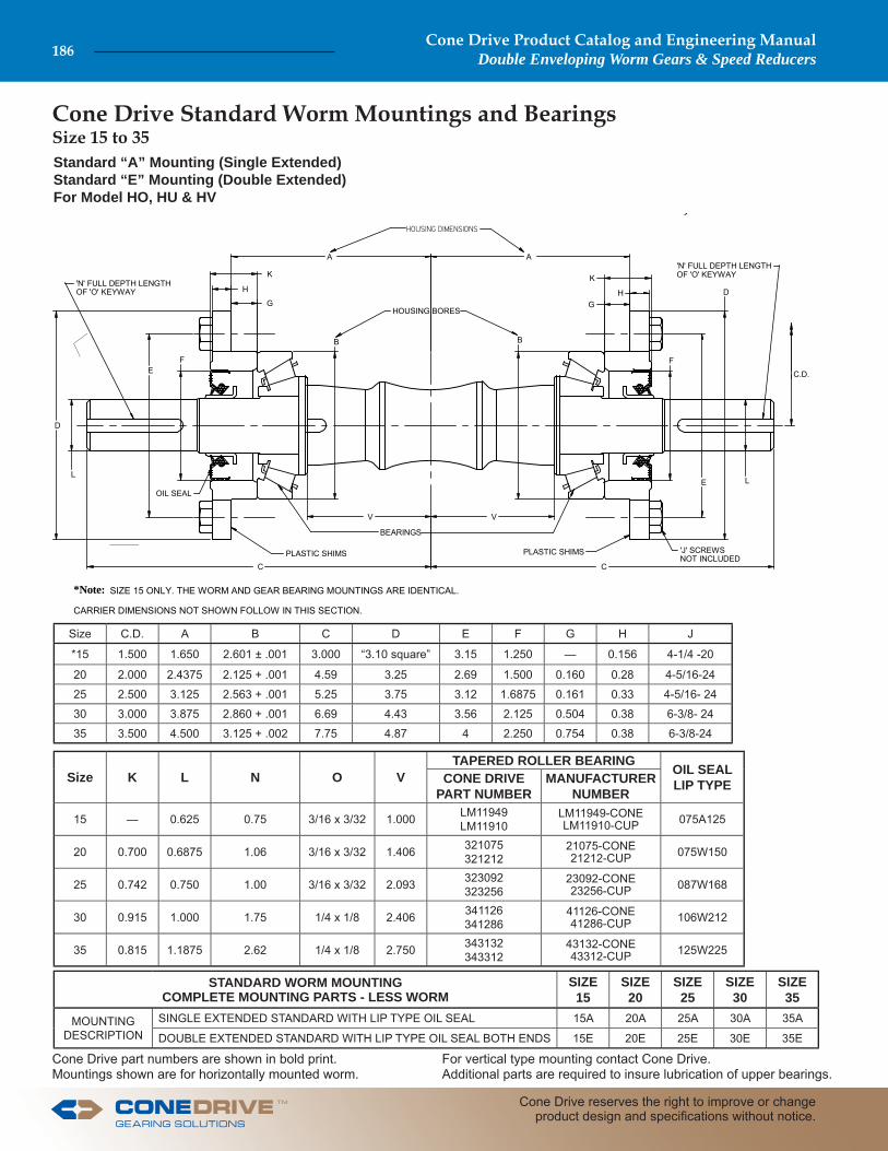
Standard “A” Mounting (Single Extended)Standard “E” Mounting (Double Extended)For Model HO, HU & HV
SIZE 15 ONLY. THE WORM AND GEAR BEARING MOUNTINGS ARE IDENTICAL.
CARRIER DIMENSIONS NOT SHOWN FOLLOW IN THIS SECTION.
,
*Note:
A A
K
H
G
K
HG
B B
V V
L
EF
D
C C
D
F
E L
C.D.
'N' FULL DEPTH LENGTHOF 'O' KEYWAY
'N' FULL DEPTH LENGTHOF 'O' KEYWAY
'J' SCREWSNOT INCLUDED
BEARINGS
HOUSING BORES
PLASTIC SHIMS PLASTIC SHIMS
OIL SEAL
Size C.D. A B C D E F G H J
*15 1.500 1.650 2.601 ± .001 3.000 “3.10 square” 3.15 1.250 — 0.156 4-1/4 -20
20 2.000 2.4375 2.125 + .001 4.59 3.25 2.69 1.500 0.160 0.28 4-5/16-24
25 2.500 3.125 2.563 + .001 5.25 3.75 3.12 1.6875 0.161 0.33 4-5/16- 24
30 3.000 3.875 2.860 + .001 6.69 4.43 3.56 2.125 0.504 0.38 6-3/8- 24
35 3.500 4.500 3.125 + .002 7.75 4.87 4 2.250 0.754 0.38 6-3/8-24
Size K L N O VTAPERED ROLLER BEARING OIL SEAL
LIP TYPECONE DRIVE PART NUMBER
MANUFACTURER NUMBER
15 — 0.625 0.75 3/16 x 3/32 1.000 LM11949LM11910
LM11949-CONELM11910-CUP 075A125
20 0.700 0.6875 1.06 3/16 x 3/32 1.406 321075321212
21075-CONE21212-CUP 075W150
25 0.742 0.750 1.00 3/16 x 3/32 2.093 323092323256
23092-CONE23256-CUP 087W168
30 0.915 1.000 1.75 1/4 x 1/8 2.406 341126341286
41126-CONE41286-CUP 106W212
35 0.815 1.1875 2.62 1/4 x 1/8 2.750 343132343312
43132-CONE43312-CUP 125W225
STANDARD WORM MOUNTINGCOMPLETE MOUNTING PARTS - LESS WORM
SIZE15
SIZE20
SIZE25
SIZE30
SIZE35
MOUNTING DESCRIPTION
SINGLE EXTENDED STANDARD WITH LIP TYPE OIL SEAL 15A 20A 25A 30A 35A
DOUBLE EXTENDED STANDARD WITH LIP TYPE OIL SEAL BOTH ENDS 15E 20E 25E 30E 35E
Size 15 to 35 Cone Drive Standard Worm Mountings and Bearings
Cone Drive Product Catalog and Engineering ManualDouble Enveloping Worm Gears & Speed Reducers186
Cone Drive reserves the right to improve or change product design and specifi cations without notice.
TM
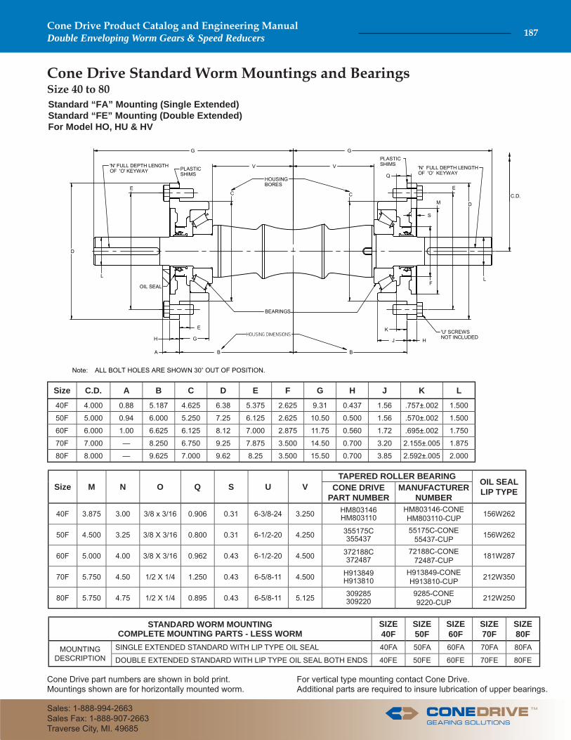
Cone Drive Standard Worm Mountings and BearingsSize 40 to 80Standard “FA” Mounting (Single Extended)Standard “FE” Mounting (Double Extended)For Model HO, HU & HV
ALL BOLT HOLES ARE SHOWN 30 OUT OF POSITION.Note:
G
V
H G
K
H
G
C C
L
J
E
D
B B
D
F
E
L
C.D.
'N' FULL DEPTH LENGTHOF 'O' KEYWAY 'N' FULL DEPTH LENGTH
OF 'O' KEYWAY
'U' SCREWSNOT INCLUDED
BEARINGS
HOUSING BORES
PLASTIC SHIMS
PLASTIC SHIMS
OIL SEAL
V
E
S
M
Q
A
Size C.D. A B C D E F G H J K L
40F 4.000 0.88 5.187 4.625 6.38 5.375 2.625 9.31 0.437 1.56 .757±.002 1.500
50F 5.000 0.94 6.000 5.250 7.25 6.125 2.625 10.50 0.500 1.56 .570±.002 1.500
60F 6.000 1.00 6.625 6.125 8.12 7.000 2.875 11.75 0.560 1.72 .695±.002 1.750
70F 7.000 — 8.250 6.750 9.25 7.875 3.500 14.50 0.700 3.20 2.155±.005 1.875
80F 8.000 — 9.625 7.000 9.62 8.25 3.500 15.50 0.700 3.85 2.592±.005 2.000
Size M N O Q S U VTAPERED ROLLER BEARING OIL SEAL
LIP TYPECONE DRIVE PART NUMBER
MANUFACTURER NUMBER
40F 3.875 3.00 3/8 x 3/16 0.906 0.31 6-3/8-24 3.250 HM803146HM803110
HM803146-CONEHM803110-CUP 156W262
50F 4.500 3.25 3/8 X 3/16 0.800 0.31 6-1/2-20 4.250 355175C355437
55175C-CONE55437-CUP 156W262
60F 5.000 4.00 3/8 X 3/16 0.962 0.43 6-1/2-20 4.500 372188C372487
72188C-CONE72487-CUP 181W287
70F 5.750 4.50 1/2 X 1/4 1.250 0.43 6-5/8-11 4.500 H913849H913810
H913849-CONEH913810-CUP 212W350
80F 5.750 4.75 1/2 X 1/4 0.895 0.43 6-5/8-11 5.125 309285309220
9285-CONE9220-CUP 212W250
STANDARD WORM MOUNTINGCOMPLETE MOUNTING PARTS - LESS WORM
SIZE40F
SIZE50F
SIZE60F
SIZE70F
SIZE80F
MOUNTING DESCRIPTION
SINGLE EXTENDED STANDARD WITH LIP TYPE OIL SEAL 40FA 50FA 60FA 70FA 80FA
DOUBLE EXTENDED STANDARD WITH LIP TYPE OIL SEAL BOTH ENDS 40FE 50FE 60FE 70FE 80FE
For vertical type mounting contact Cone Drive.Additional parts are required to insure lubrication of upper bearings.
Cone Drive part numbers are shown in bold print.Mountings shown are for horizontally mounted worm.
TM
Cone Drive Product Catalog and Engineering ManualDouble Enveloping Worm Gears & Speed Reducers 187
Sales: 1-888-994-2663Sales Fax: 1-888-907-2663Traverse City, MI. 49685
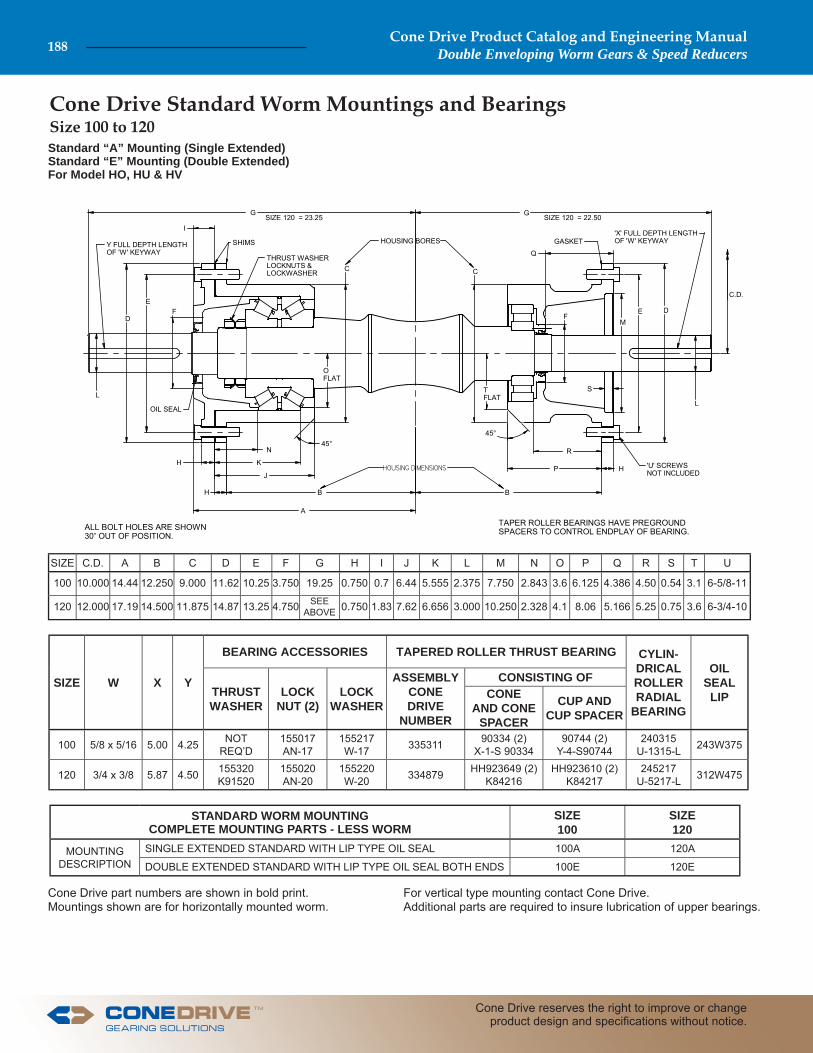
Cone Drive Standard Worm Mountings and Bearings Size 100 to 120
For vertical type mounting contact Cone Drive.Additional parts are required to insure lubrication of upper bearings.
Cone Drive part numbers are shown in bold print.Mountings shown are for horizontally mounted worm.
ALL BOLT HOLES ARE SHOWN30 OUT OF POSITION.
TAPER ROLLER BEARINGS HAVE PREGROUNDSPACERS TO CONTROL ENDPLAY OF BEARING.
B B
KH
J
G
F
S
C C
G
E
L
FD
P
D
M
L
C.D.
Y FULL DEPTH LENGTHOF 'W' KEYWAY
'X' FULL DEPTH LENGTHOF 'W' KEYWAY
'U' SCREWSNOT INCLUDED
THRUST WASHERLOCKNUTS &LOCKWASHER
HOUSING BORESSHIMS GASKET
OIL SEAL
E
45°
A
H
N
OFLAT
SIZE 120 = 23.25 SIZE 120 = 22.50
R
TFLAT
H
Q
45°
I
Standard “A” Mounting (Single Extended)Standard “E” Mounting (Double Extended)For Model HO, HU & HV
SIZE C.D. A B C D E F G H I J K L M N O P Q R S T U
100 10.000 14.44 12.250 9.000 11.62 10.25 3.750 19.25 0.750 0.7 6.44 5.555 2.375 7.750 2.843 3.6 6.125 4.386 4.50 0.54 3.1 6-5/8-11
120 12.000 17.19 14.500 11.875 14.87 13.25 4.750 SEE ABOVE 0.750 1.83 7.62 6.656 3.000 10.250 2.328 4.1 8.06 5.166 5.25 0.75 3.6 6-3/4-10
SIZE W X Y
BEARING ACCESSORIES TAPERED ROLLER THRUST BEARING CYLIN-DRICALROLLERRADIAL
BEARING
OIL SEAL LIPTHRUST
WASHERLOCK
NUT (2)LOCK
WASHER
ASSEMBLY CONE DRIVE
NUMBER
CONSISTING OFCONE
AND CONE SPACER
CUP AND CUP SPACER
100 5/8 x 5/16 5.00 4.25 NOTREQ’D
155017AN-17
155217W-17 335311 90334 (2)
X-1-S 9033490744 (2)
Y-4-S90744240315
U-1315-L 243W375
120 3/4 x 3/8 5.87 4.50 155320K91520
155020AN-20
155220W-20 334879 HH923649 (2)
K84216HH923610 (2)
K84217245217
U-5217-L 312W475
STANDARD WORM MOUNTINGCOMPLETE MOUNTING PARTS - LESS WORM
SIZE100
SIZE120
MOUNTING DESCRIPTION
SINGLE EXTENDED STANDARD WITH LIP TYPE OIL SEAL 100A 120A
DOUBLE EXTENDED STANDARD WITH LIP TYPE OIL SEAL BOTH ENDS 100E 120E
Cone Drive Product Catalog and Engineering ManualDouble Enveloping Worm Gears & Speed Reducers188
Cone Drive reserves the right to improve or change product design and specifi cations without notice.
TM
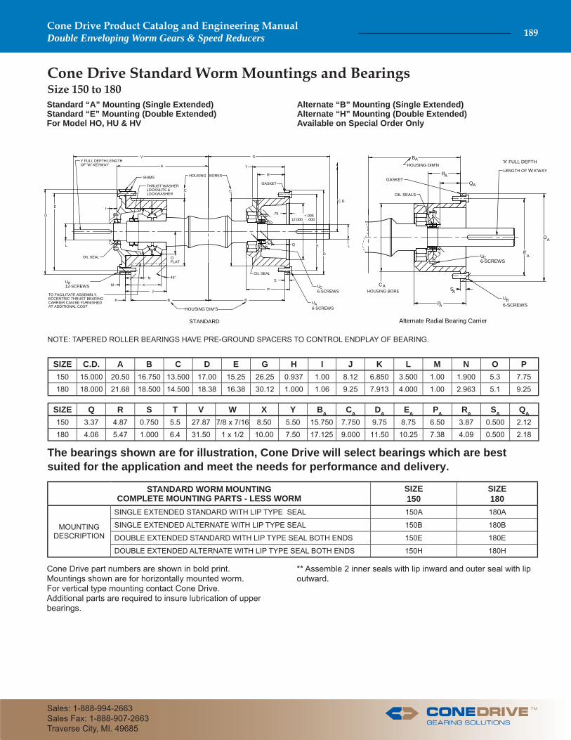
Cone Drive Standard Worm Mountings and Bearings Size 150 to 180Standard “A” Mounting (Single Extended)Standard “E” Mounting (Double Extended)For Model HO, HU & HV
Alternate “B” Mounting (Single Extended)Alternate “H” Mounting (Double Extended)Available on Special Order Only
NOTE: TAPERED ROLLER BEARINGS HAVE PRE-GROUND SPACERS TO CONTROL ENDPLAY OF BEARING.
** Assemble 2 inner seals with lip inward and outer seal with lip outward.
Cone Drive part numbers are shown in bold print.Mountings shown are for horizontally mounted worm.For vertical type mounting contact Cone Drive.Additional parts are required to insure lubrication of upper bearings.
SIZE C.D. A B C D E G H I J K L M N O P150 15.000 20.50 16.750 13.500 17.00 15.25 26.25 0.937 1.00 8.12 6.850 3.500 1.00 1.900 5.3 7.75180 18.000 21.68 18.500 14.500 18.38 16.38 30.12 1.000 1.06 9.25 7.913 4.000 1.00 2.963 5.1 9.25
SIZE Q R S T V W X Y BA CA DA EA PA RA SA QA
150 3.37 4.87 0.750 5.5 27.87 7/8 x 7/16 8.50 5.50 15.750 7.750 9.75 8.75 6.50 3.87 0.500 2.12180 4.06 5.47 1.000 6.4 31.50 1 x 1/2 10.00 7.50 17.125 9.000 11.50 10.25 7.38 4.09 0.500 2.18
STANDARD WORM MOUNTINGCOMPLETE MOUNTING PARTS - LESS WORM
SIZE150
SIZE180
MOUNTING DESCRIPTION
SINGLE EXTENDED STANDARD WITH LIP TYPE SEAL 150A 180A
SINGLE EXTENDED ALTERNATE WITH LIP TYPE SEAL 150B 180B
DOUBLE EXTENDED STANDARD WITH LIP TYPE SEAL BOTH ENDS 150E 180E
DOUBLE EXTENDED ALTERNATE WITH LIP TYPE SEAL BOTH ENDS 150H 180H
B B
KM
J
V
C
G
E
L
D
D
12.000 - .000 +.005
L
C.D.
Y FULL DEPTH LENGTHOF 'W' KEYWAY
THRUST WASHERLOCKNUTS &LOCKWASHER
HOUSING BORESSHIMS
GASKET
OIL SEAL
E
45°
H
N
OFLAT
R
P
T
I
STANDARD
C
A
U6-SCREWS
U6-SCREWS
A
C
Q
OIL SEAL
S
TO FACILITATE ASSEMBLY,ECCENTRIC THRUST BEARINGCARRIER CAN BE FURNISHEDAT ADDITIONAL COST
U12-SCREWS
A
.75
HOUSING DIM’S
D
EA
A
Alternate Radial Bearing Carrier
B
R
Q
S
P
A
A
A
A
A
CAHOUSING BORE
HOUSING DIM'N
GASKET
OIL SEALS
U6-SCREWS
U6-SCREWS
B
C
LENGTH OF K'WAYW
'X' FULL DEPTH
The bearings shown are for illustration, Cone Drive will select bearings which are best suited for the application and meet the needs for performance and delivery.
TM
Cone Drive Product Catalog and Engineering ManualDouble Enveloping Worm Gears & Speed Reducers 189
Sales: 1-888-994-2663Sales Fax: 1-888-907-2663Traverse City, MI. 49685
NOTE: TAPERED ROLLER BEARINGS HAVE PRE-GROUND SPACERS TO CONTROL ENDPLAY OF BEARING.
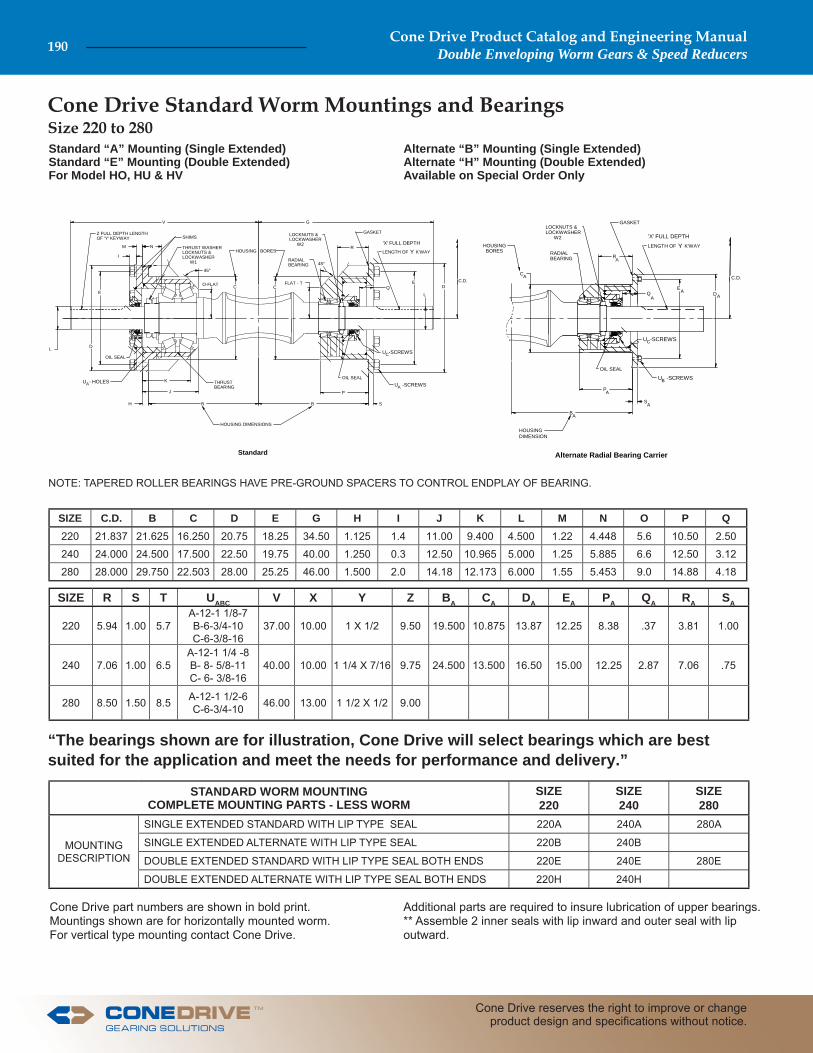
SIZE R S T UABC V X Y Z BA CA DA EA PA QA RA SA
220 5.94 1.00 5.7A-12-1 1/8-7B-6-3/4-10C-6-3/8-16
37.00 10.00 1 X 1/2 9.50 19.500 10.875 13.87 12.25 8.38 .37 3.81 1.00
240 7.06 1.00 6.5A-12-1 1/4 -8B- 8- 5/8-11C- 6- 3/8-16
40.00 10.00 1 1/4 X 7/16 9.75 24.500 13.500 16.50 15.00 12.25 2.87 7.06 .75
280 8.50 1.50 8.5 A-12-1 1/2-6C-6-3/4-10 46.00 13.00 1 1/2 X 1/2 9.00
STANDARD WORM MOUNTINGCOMPLETE MOUNTING PARTS - LESS WORM
SIZE220
SIZE240
SIZE280
MOUNTING DESCRIPTION
SINGLE EXTENDED STANDARD WITH LIP TYPE SEAL 220A 240A 280A
SINGLE EXTENDED ALTERNATE WITH LIP TYPE SEAL 220B 240B
DOUBLE EXTENDED STANDARD WITH LIP TYPE SEAL BOTH ENDS 220E 240E 280E
DOUBLE EXTENDED ALTERNATE WITH LIP TYPE SEAL BOTH ENDS 220H 240H
Alternate “B” Mounting (Single Extended)Alternate “H” Mounting (Double Extended)Available on Special Order Only
Cone Drive Standard Worm Mountings and Bearings Size 220 to 280Standard “A” Mounting (Single Extended)Standard “E” Mounting (Double Extended)For Model HO, HU & HV
Cone Drive part numbers are shown in bold print.Mountings shown are for horizontally mounted worm.For vertical type mounting contact Cone Drive.
Additional parts are required to insure lubrication of upper bearings.** Assemble 2 inner seals with lip inward and outer seal with lip outward.
SIZE C.D. B C D E G H I J K L M N O P Q220 21.837 21.625 16.250 20.75 18.25 34.50 1.125 1.4 11.00 9.400 4.500 1.22 4.448 5.6 10.50 2.50
240 24.000 24.500 17.500 22.50 19.75 40.00 1.250 0.3 12.50 10.965 5.000 1.25 5.885 6.6 12.50 3.12
280 28.000 29.750 22.503 28.00 25.25 46.00 1.500 2.0 14.18 12.173 6.000 1.55 5.453 9.0 14.88 4.18
HOUSING DIMENSIONS
C.D.
Z FULL DEPTH LENGTHOF 'Y' KEYWAY
THRUST WASHERLOCKNUTS &LOCKWASHER W1
HOUSING BORES
SHIMS
OIL SEAL
Standard
U -SCREWS
U -SCREWSA
C
OIL SEALTHRUSTBEARING
U - HOLESA
GASKET
C C
D
E
L
B BH
J
K
I
M N
45°
O-FLAT FLAT - T
P
S
V G
LOCKNUTS &LOCKWASHER W2
RADIALBEARING
DE
LQ
RLENGTH OF K'WAYY'X' FULL DEPTH
45°
HOUSING DIMENSION
C.D.
HOUSING BORES
Alternate Radial Bearing Carrier
U -SCREWS
U -SCREWSB
C
OIL SEAL
GASKET
C
B
P
S
LOCKNUTS &LOCKWASHER W2
RADIALBEARING
DE
Q
R
LENGTH OF K'WAYY'X' FULL DEPTH
A
A
A
A
AAA
A
“The bearings shown are for illustration, Cone Drive will select bearings which are best suited for the application and meet the needs for performance and delivery.”
Cone Drive Product Catalog and Engineering ManualDouble Enveloping Worm Gears & Speed Reducers190
Cone Drive reserves the right to improve or change product design and specifi cations without notice.
TM
A A
JH
G
M H
G
C C
E
B
K
E
F
B
J
D
D
F
M
K
C.D.
'N' FULL DEPTH LENGTHOF 'O' KEYWAY
'N' FULL DEPTH LENGTHOF 'O' KEYWAY
'L' SCREWSNOT INCLUDED
BEARINGS
HOUSING BORES
PLASTIC SHIMS PLASTIC SHIMS
OIL SEAL
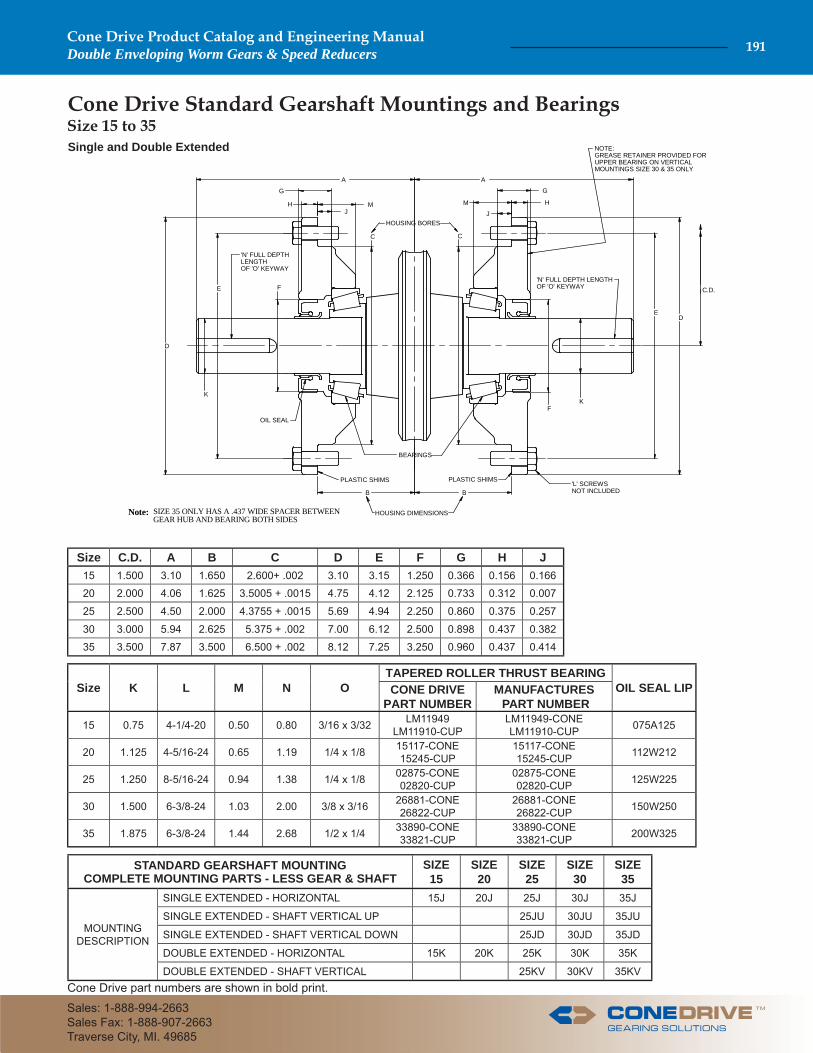
SIZE 35 ONLY HAS A .437 WIDE SPACER BETWEENGEAR HUB AND BEARING BOTH SIDES
Note:
NOTE:GREASE RETAINER PROVIDED FORUPPER BEARING ON VERTICAL MOUNTINGS SIZE 30 & 35 ONLY
HOUSING DIMENSIONS
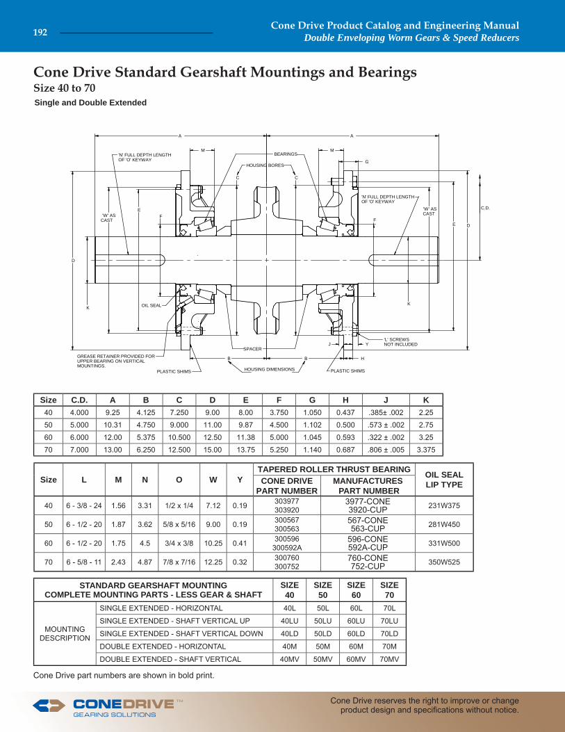
Cone Drive Standard Gearshaft Mountings and Bearings
Single and Double Extended
Cone Drive part numbers are shown in bold print.
Size C.D. A B C D E F G H J15 1.500 3.10 1.650 2.600+ .002 3.10 3.15 1.250 0.366 0.156 0.166
20 2.000 4.06 1.625 3.5005 + .0015 4.75 4.12 2.125 0.733 0.312 0.007
25 2.500 4.50 2.000 4.3755 + .0015 5.69 4.94 2.250 0.860 0.375 0.257
30 3.000 5.94 2.625 5.375 + .002 7.00 6.12 2.500 0.898 0.437 0.382
35 3.500 7.87 3.500 6.500 + .002 8.12 7.25 3.250 0.960 0.437 0.414
Size K L M N OTAPERED ROLLER THRUST BEARING
OIL SEAL LIPCONE DRIVE PART NUMBER
MANUFACTURES PART NUMBER
15 0.75 4-1/4-20 0.50 0.80 3/16 x 3/32 LM11949LM11910-CUP
LM11949-CONELM11910-CUP 075A125
20 1.125 4-5/16-24 0.65 1.19 1/4 x 1/8 15117-CONE15245-CUP
15117-CONE15245-CUP 112W212
25 1.250 8-5/16-24 0.94 1.38 1/4 x 1/8 02875-CONE02820-CUP
02875-CONE02820-CUP 125W225
30 1.500 6-3/8-24 1.03 2.00 3/8 x 3/16 26881-CONE26822-CUP
26881-CONE26822-CUP 150W250
35 1.875 6-3/8-24 1.44 2.68 1/2 x 1/4 33890-CONE33821-CUP
33890-CONE33821-CUP 200W325
STANDARD GEARSHAFT MOUNTINGCOMPLETE MOUNTING PARTS - LESS GEAR & SHAFT
SIZE15
SIZE20
SIZE25
SIZE30
SIZE35
MOUNTING DESCRIPTION
SINGLE EXTENDED - HORIZONTAL 15J 20J 25J 30J 35J
SINGLE EXTENDED - SHAFT VERTICAL UP 25JU 30JU 35JU
SINGLE EXTENDED - SHAFT VERTICAL DOWN 25JD 30JD 35JD
DOUBLE EXTENDED - HORIZONTAL 15K 20K 25K 30K 35K
DOUBLE EXTENDED - SHAFT VERTICAL 25KV 30KV 35KV
Size 15 to 35
TM
Cone Drive Product Catalog and Engineering ManualDouble Enveloping Worm Gears & Speed Reducers 191
Sales: 1-888-994-2663Sales Fax: 1-888-907-2663Traverse City, MI. 49685
A A
G
Y
'W' AS CAST
M
H
'W' AS CAST
C C
E
B
K
E
F
B
J
D
DF
M
K
C.D.
'N' FULL DEPTH LENGTHOF 'O' KEYWAY
'N' FULL DEPTH LENGTHOF 'O' KEYWAY
'L' SCREWSNOT INCLUDED
BEARINGS
HOUSING BORES
HOUSING DIMENSIONSPLASTIC SHIMS PLASTIC SHIMS
SPACERGREASE RETAINER PROVIDED FORUPPER BEARING ON VERTICAL MOUNTINGS.
OIL SEAL
Cone Drive Standard Gearshaft Mountings and Bearings Size 40 to 70Single and Double Extended
Cone Drive part numbers are shown in bold print.
Size C.D. A B C D E F G H J K40 4.000 9.25 4.125 7.250 9.00 8.00 3.750 1.050 0.437 .385± .002 2.25
50 5.000 10.31 4.750 9.000 11.00 9.87 4.500 1.102 0.500 .573 ± .002 2.75
60 6.000 12.00 5.375 10.500 12.50 11.38 5.000 1.045 0.593 .322 ± .002 3.25
70 7.000 13.00 6.250 12.500 15.00 13.75 5.250 1.140 0.687 .806 ± .005 3.375
Size L M N O W YTAPERED ROLLER THRUST BEARING OIL SEAL
LIP TYPECONE DRIVE PART NUMBER
MANUFACTURES PART NUMBER
40 6 - 3/8 - 24 1.56 3.31 1/2 x 1/4 7.12 0.19 303977303920
3977-CONE3920-CUP 231W375
50 6 - 1/2 - 20 1.87 3.62 5/8 x 5/16 9.00 0.19 300567300563
567-CONE563-CUP 281W450
60 6 - 1/2 - 20 1.75 4.5 3/4 x 3/8 10.25 0.41 300596300592A
596-CONE592A-CUP 331W500
70 6 - 5/8 - 11 2.43 4.87 7/8 x 7/16 12.25 0.32 300760300752
760-CONE752-CUP 350W525
STANDARD GEARSHAFT MOUNTINGCOMPLETE MOUNTING PARTS - LESS GEAR & SHAFT
SIZE40
SIZE50
SIZE60
SIZE70
MOUNTING DESCRIPTION
SINGLE EXTENDED - HORIZONTAL 40L 50L 60L 70L
SINGLE EXTENDED - SHAFT VERTICAL UP 40LU 50LU 60LU 70LU
SINGLE EXTENDED - SHAFT VERTICAL DOWN 40LD 50LD 60LD 70LD
DOUBLE EXTENDED - HORIZONTAL 40M 50M 60M 70M
DOUBLE EXTENDED - SHAFT VERTICAL 40MV 50MV 60MV 70MV
Cone Drive Product Catalog and Engineering ManualDouble Enveloping Worm Gears & Speed Reducers192
Cone Drive reserves the right to improve or change product design and specifi cations without notice.
TM
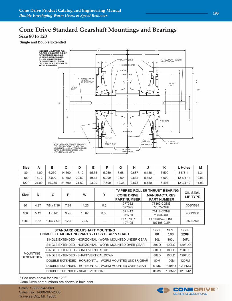
Cone Drive Standard Gearshaft Mountings and Bearings Size 80 to 120Single and Double Extended
A A
YY
'W' AS CAST
H
'W' AS CAST
C C
E
B
K
E
B
D
D
F
K
C.D.
'N' FULL DEPTH LENGTHOF 'O' KEYWAY
'N' FULL DEPTH LENGTHOF 'O' KEYWAY
'L' SCREWSNOT INCLUDED
BEARINGS
HOUSING BORES
PLASTIC SHIMS
SPACER
NOTE: GREASE RETAINER PROVIDEDFOR UPPER BEARING ON VERTICAL MOUNTINGS LU, LD,MV AND FOR BOTHBEARINGS FOR MOUNTINGS 100L, 100M, 120FL AND 120FM.
OIL SEAL
G G
M M
JSIZE 80 & 120
JSIZE 100J
SIZE 80 & 120
JSIZE 100
P
*SIZE 120F MOUNTINGS FLO,FLD,FMO AND LOWER END OF FMV REQUIRES (2) SINGLELIP SEALS. MOUNTINGS FL,FLU, FM AND UPPER ENDOF FMV REQUIRES (1) SEALONLY. ALL SEALS ASSEMBLED WITH LIPS INWARD.
HHOUSING DIMENSIONS
* See note above for size 120F.Cone Drive part numbers are shown in bold print.
Size A B C D E F G H J K L Holes M80 14.00 6.250 14.500 17.12 15.75 5.250 7.68 0.687 0.186 3.500 8 5/8-11 1.31
100 15.72 8.000 17.750 20.50 19.12 6.000 9.00 0.812 0.652 4.000 12-5/8-11 2.03
120F 24.00 10.375 21.500 24.50 23.00 7.500 12.36 0.875 0.450 5.497 12-3/4-10 1.93
Size N O P W YTAPERED ROLLER THRUST BEARING OIL SEAL
LIP TYPECONE DRIVE PART NUMBER
MANUFACTURES PART NUMBER
80 4.87 7/8 x 7/16 7.84 14.25 0.5 377362377675
77362-CONE77675-CUP 356W525
100 5.12 1 x 1/2 9.25 16.82 0.38 371412371750
71412-CONE71750-CUP 406W600
120F 7.62 1 1/4 x 5/8 12.5 20.5 — EE107057107105
EE107057-CONE107105-CUP 550A750
STANDARD GEARSHAFT MOUNTINGCOMPLETE MOUNTING PARTS - LESS GEAR & SHAFT
SIZE80
SIZE100
SIZE120F
MOUNTING DESCRIPTION
SINGLE EXTENDED - HORIZONTAL - WORM MOUNTED UNDER GEAR 80L 100L 120FL
SINGLE EXTENDED - HORIZONTAL - WORM MOUNTED OVER GEAR 80LO 100LO 120FLO
SINGLE EXTENDED - SHAFT VERTICAL UP 80LU 100LU 120FLU
SINGLE EXTENDED - SHAFT VERTICAL DOWN 80LD 100LD 120FLD
DOUBLE EXTENDED - HORIZONTAL - WORM MOUNTED UNDER GEAR 80M 100M 120FM
DOUBLE EXTENDED - HORIZONTAL - WORM MOUNTED OVER GEAR 80MO 100MO 120FMO
DOUBLE EXTENDED - SHAFT VERTICAL 80MV 100MV 120FMV
TM
Cone Drive Product Catalog and Engineering ManualDouble Enveloping Worm Gears & Speed Reducers 193
Sales: 1-888-994-2663Sales Fax: 1-888-907-2663Traverse City, MI. 49685
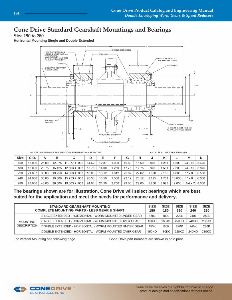
Cone Drive Standard Gearshaft Mountings and Bearings
For Vertical Mounting see following page. Cone Drive part numbers are shown in bold print.
Horizontal Mounting Single and Double Extended
Size C.D. A B C D E F G H J K L M N150 15.000 25.00 12.875 11.377 + .002 14.62 12.87 1.000 15.50 15.50 .875 1.281 6.500 3/4 - 10 5.625
180 18.000 28.75 15.125 12.503 + .003 15.75 14.00 1.250 17.75 17.75 .875 1.531 7.500 3/4 - 10 5.875
220 21.837 36.00 19.750 14.003 + .003 18.00 16.12 1.812 22.62 22.62 1.000 2.156 9.000 1" x 8 6.500
240 24.000 38.00 19.500 15.753 + .003 20.50 18.50 1.500 23.12 23.12 1.125 1.781 10.000 1" x 8 6.000
280 28.000 48.00 26.500 19.003 + .003 24.00 21.50 2.750 29.00 29.00 1.250 3.028 12.000 1 1/4 x 7 8.000
STANDARD GEARSHAFT MOUNTINGCOMPLETE MOUNTING PARTS - LESS GEAR & SHAFT
SIZE150
SIZE180
SIZE220
SIZE240
SIZE280
MOUNTING DESCRIPTION
SINGLE EXTENDED - HORIZONTAL - WORM MOUNTED UNDER GEAR 150L 180L 220L 240L 280L
SINGLE EXTENDED - HORIZONTAL - WORM MOUNTED OVER GEAR 150JO 180JO 220JO 240JO 280JO
DOUBLE EXTENDED - HORIZONTAL - WORM MOUNTED UNDER GEAR 150K 180K 220K 240K 280K
DOUBLE EXTENDED - HORIZONTAL - WORM MOUNTED OVER GEAR 150KO 180KO 220KO 240KO 280KO
LOCATE LARGE END OF SPACERS TOWARD BEARINGS ON MOUNTING.
HOUSING DIMENSIONS
C.D.
2 KEYWAYS 180° APARTR SIZE S LONG
LOCK THIS BEARING INHOUSING, MUST TAKE ALLTHRUST LOAD.SPACER WIDTH MACHINEDTO SUIT AT ASSEMBLY.
HOUSING BORES
SHIMS
LOCKNUT &WASHER
M - SCREWS
GASKET
BEARINGS
A A
D
E
L
Q
H
B B
G
J
C C
N O
E
D
J
F 8 - HOLES ON SIZE 150 & 18012- HOLES ON SIZES 220-280K
L
RADIAL BEARING NOTLOCKED IN HOUSING.
ALL OIL SEAL LIPS TO FACE INWARD.
HOUSING DIMENSIONS
Size 150 to 280
The bearings shown are for illustration, Cone Drive will select bearings which are best suited for the application and meet the needs for performance and delivery.
Cone Drive Product Catalog and Engineering ManualDouble Enveloping Worm Gears & Speed Reducers194
Cone Drive reserves the right to improve or change product design and specifi cations without notice.
TM
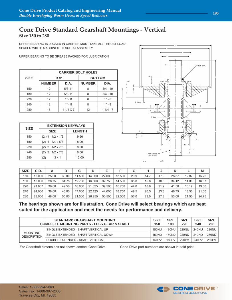
Cone Drive Standard Gearshaft Mountings - Vertical
UPPER BEARING IS LOCKED IN CARRIER MUST TAKE ALL THRUST LOAD, SPACER WIDTH MACHINED TO SUIT AT ASSEMBLY.
UPPER BEARING TO BE GREASE PACKED FOR LUBRICATION
For Gearshaft dimensions not shown contact Cone Drive. Cone Drive part numbers are shown in bold print.
SIZE C.D. A B C D E F G H J K L M150 15.000 25.00 30.00 11.500 14.000 27.000 13.500 29.9 14.7 17.0 28.37 12.87 15.25
180 18.000 28.75 34.75 12.750 16.500 32.750 14.500 35.8 15.8 18.5 34.12 14.00 16.37
220 21.837 36.00 42.50 16.000 21.625 39.500 16.750 44.0 18.0 21.2 41.50 16.12 19.00
240 24.000 38.00 46.00 17.000 22.125 44.000 18.750 49.5 20.5 23.3 46.75 18.50 21.00
280 28.000 48.00 55.00 21.500 26.250 50.500 22.500 56.0 23.0 27.8 53.00 21.50 24.75
STANDARD GEARSHAFT MOUNTINGCOMPLETE MOUNTING PARTS - LESS GEAR & SHAFT
SIZE150
SIZE180
SIZE220
SIZE240
SIZE280
MOUNTING DESCRIPTION
SINGLE EXTENDED - SHAFT VERTICAL UP 150NU 180NU 220NU 240NU 280NU
SINGLE EXTENDED - SHAFT VERTICAL DOWN 150ND 180ND 220ND 240ND 280ND
DOUBLE EXTENDED - SHAFT VERTICAL 150PV 180PV 220PV 240PV 280PV
SIZECARRIER BOLT HOLES
TOP BOTTOMNUMBER DIA. NUMBER DIA.
150 12 5/8-11 8 3/4 - 10
180 12 5/8-11 8 3/4 - 10
220 12 1” - 8 8 1” - 8
240 12 1” - 8 8 1” - 8
280 16 1 1/4 X 7 12 1 1/4 - 7
SIZEEXTENSION KEYWAYSSIZE LENGTH
150 (2 ) 1 1/2 x 1/2 9.50
180 (2) 1 3/4 x 5/8 8.00
220 (2) 2 1/2 x 7/8 8.00
240 (2) 2 1/2 x 7/8 8.00
280 (2) 3 x 1 12.00 2 KEYWAYS 180° APART
G
T
C
K
H
B
D
'F' Bore
Q
T
L
E Bore
P
O
R
N
TOP SEAL
M
J
A
C.D.
S
N
Size 150 to 280
The bearings shown are for illustration, Cone Drive will select bearings which are best suited for the application and meet the needs for performance and delivery.
TM
Cone Drive Product Catalog and Engineering ManualDouble Enveloping Worm Gears & Speed Reducers 195
Sales: 1-888-994-2663Sales Fax: 1-888-907-2663Traverse City, MI. 49685

Cone Drive part numbers are shown in bold print.
Size C.D. A B C D E F G H20 2.000 3.06 1.625 ± .0015
3.5005 4.75 4.12 2.687 2.43 2.62
25 2.500 3.12 2.000 ± .00154.3755 5.69 4.94 3.500 2.41 2.68
30 3.000 4.06 2.625 ± .0025.375 7.00 6.12 4.250 3.38 3.56
35 3.500 4.62 3.500 ± .0026.500 8.12 7.25 4.750 3.94 4.18
STANDARD GEARSHAFT MOUNTINGCOMPLETE MOUNTING PARTS - LESS GEAR & SHAFT
SIZE20
SIZE25
SIZE30
SIZE35
MOUNTING DESCRIPTION
SINGLE EXTENDED - SHAFT HORIZONTAL S20 J S25 J S30 J S35 J
SINGLE EXTENDED - SHAFT VERTICAL UP S20 JU S25 JU S30 JU S35 JU
SINGLE EXTENDED - SHAFT VERTICAL DOWN S20 JD S25 JD S30 JD S35 JD
Cone Drive Standard Gearshaft Mountings and Bearings
J
I
K
B I
K
C ** C **
E
E
F
B
DF
D
*BORE DIA.
C.D.
5/16-24 TAP, 2-HOLES90 APART
'L' SCREWSNOT INCLUDED
BEARINGS
HOUSING BORESPLASTIC SHIMS
PLASTIC SHIMS
OIL SEALS
NOTE:GREASE RETAINER PROVIDED FORUPPER BEARING ON VERTICAL MOUNTINGS.
G G
*SEE GEAR SHAFT CHART FOR BORE SIZES FOLLOWING IN THIS SECTION.**ON SIZES 20 & 25 THE BEARINGS SET DIRECTLY IN HOUSING BORE.
H A
J
KEY WAY
SIZE I J KL HOLES TAPERERED ROLLER BEARING OIL SEAL
LIP TYPENO. SIZE CONE DRIVE PART NUMBER
MANUFACTURES PART NUMBER
20 .375 -.118 1.750 4 5/16 - 24 300368300362A
368-CONE362A-CUP 193W268
25 .375 .203 - 8 5/16 - 24 30399A30393AS
399A-CONE393AS-CUP 262W350
30 .437 -0.56 2.687 6 3/8 - 24 327689327620
27689-CONE27620-CUP 325W425
35 .437 .382 - 6 3/8 - 24 342368342584
42368-CONE42584-CUP 362W475
Size 20 to 35
Cone Drive Product Catalog and Engineering ManualDouble Enveloping Worm Gears & Speed Reducers196
Cone Drive reserves the right to improve or change product design and specifi cations without notice.
TM
Cone Drive part numbers are shown in bold print.
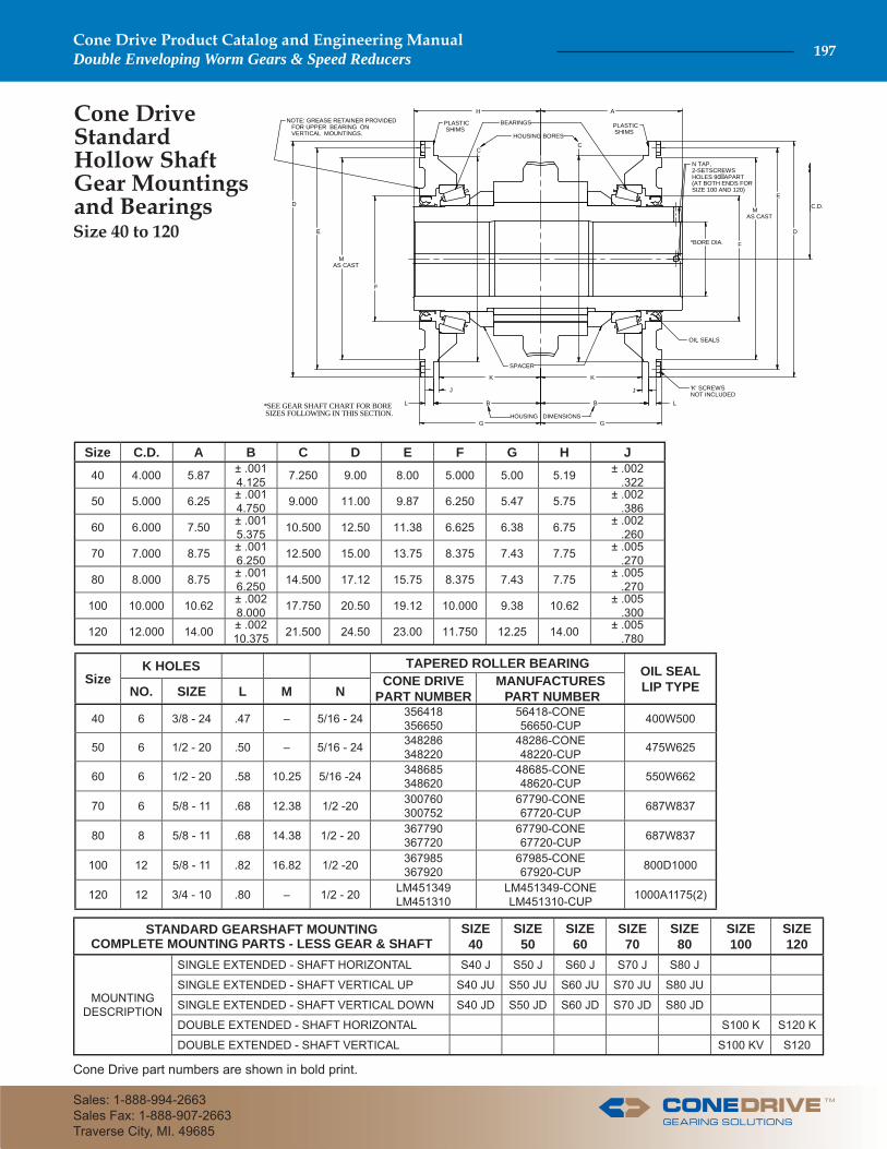
Cone Drive Standard Hollow Shaft Gear Mountings and Bearings
Size C.D. A B C D E F G H J40 4.000 5.87 ± .001
4.125 7.250 9.00 8.00 5.000 5.00 5.19 ± .002 .322
50 5.000 6.25 ± .0014.750 9.000 11.00 9.87 6.250 5.47 5.75 ± .002
.38660 6.000 7.50 ± .001
5.375 10.500 12.50 11.38 6.625 6.38 6.75 ± .002 .260
70 7.000 8.75 ± .0016.250 12.500 15.00 13.75 8.375 7.43 7.75 ± .005
.27080 8.000 8.75 ± .001
6.250 14.500 17.12 15.75 8.375 7.43 7.75 ± .005 .270
100 10.000 10.62 ± .0028.000 17.750 20.50 19.12 10.000 9.38 10.62 ± .005
.300120 12.000 14.00 ± .002
10.375 21.500 24.50 23.00 11.750 12.25 14.00 ± .005 .780
SizeK HOLES TAPERED ROLLER BEARING OIL SEAL
LIP TYPECONE DRIVE PART NUMBER
MANUFACTURES PART NUMBERNO. SIZE L M N
40 6 3/8 - 24 .47 – 5/16 - 24 356418356650
56418-CONE56650-CUP 400W500
50 6 1/2 - 20 .50 – 5/16 - 24 348286348220
48286-CONE48220-CUP 475W625
60 6 1/2 - 20 .58 10.25 5/16 -24 348685348620
48685-CONE48620-CUP 550W662
70 6 5/8 - 11 .68 12.38 1/2 -20 300760300752
67790-CONE67720-CUP 687W837
80 8 5/8 - 11 .68 14.38 1/2 - 20 367790367720
67790-CONE67720-CUP 687W837
100 12 5/8 - 11 .82 16.82 1/2 -20 367985367920
67985-CONE67920-CUP 800D1000
120 12 3/4 - 10 .80 – 1/2 - 20 LM451349LM451310
LM451349-CONELM451310-CUP 1000A1175(2)
STANDARD GEARSHAFT MOUNTINGCOMPLETE MOUNTING PARTS - LESS GEAR & SHAFT
SIZE40
SIZE50
SIZE60
SIZE70
SIZE80
SIZE100
SIZE120
MOUNTING DESCRIPTION
SINGLE EXTENDED - SHAFT HORIZONTAL S40 J S50 J S60 J S70 J S80 J
SINGLE EXTENDED - SHAFT VERTICAL UP S40 JU S50 JU S60 JU S70 JU S80 JU
SINGLE EXTENDED - SHAFT VERTICAL DOWN S40 JD S50 JD S60 JD S70 JD S80 JD
DOUBLE EXTENDED - SHAFT HORIZONTAL S100 K S120 K
DOUBLE EXTENDED - SHAFT VERTICAL S100 KV S120
HOUSING DIMENSIONS
J
L
K
B L
K
CC
E
E
F
B
D
F
D
*BORE DIA.
C.D.
N TAP,2-SETSCREWS HOLES 90� APART(AT BOTH ENDS FORSIZE 100 AND 120)
'K' SCREWSNOT INCLUDED
BEARINGS
HOUSING BORES
PLASTIC SHIMS PLASTIC
SHIMS
OIL SEALS
NOTE: GREASE RETAINER PROVIDED FOR UPPER BEARING ON VERTICAL MOUNTINGS.
G G
*SEE GEAR SHAFT CHART FOR BORE SIZES FOLLOWING IN THIS SECTION.
H A
J
MAS CAST
SPACER
MAS CAST
Size 40 to 120
TM
Cone Drive Product Catalog and Engineering ManualDouble Enveloping Worm Gears & Speed Reducers 197
Sales: 1-888-994-2663Sales Fax: 1-888-907-2663Traverse City, MI. 49685
Contact Cone Drive for additional gearshaft dimensions when required.
* SIZE 25 DOUBLE EXTENDED D = 3.44( CENTER KEYWAYLENGTH = 1.69 )
N N
D C
M 2-KEYWAYS 180° APART
O O
E
G
F F
E
DIA. PDIA. HDIA. J
DIA. KDIA. PDIA. H
DIA. J
A
ASECTION A-A SECTION A-A
B
BSECTION B-B
B
B
SIZE 40 -120
M KEYWAY L KEYWAY
SIZE 20 - 35
REFER TO SECTION G FORGEARSHAFT MATERIAL
*
TAPPED HOLE BOTH ENDSSIZE 50-120
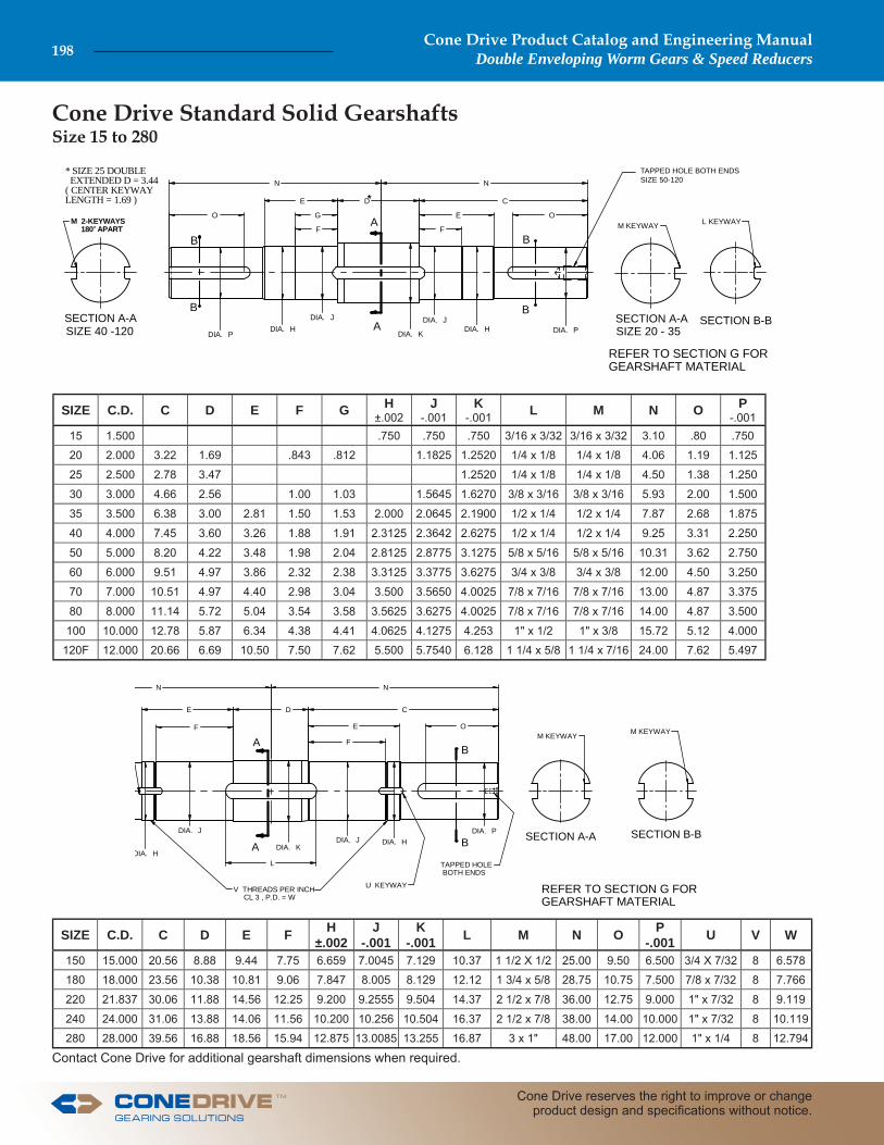
Cone Drive Standard Solid Gearshafts
A
ASECTION A-A
B
BSECTION B-B
M KEYWAY
N N
E D C
O
LDIA. H
DIA. J
DIA. KDIA. J DIA. H
DIA. P
E
F
F
V THREADS PER INCH CL 3 , P.D. = W
U KEYWAY
TAPPED HOLE BOTH ENDS
M KEYWAY
REFER TO SECTION G FORGEARSHAFT MATERIAL
SIZE C.D. C D E F G H±.002
J-.001
K-.001 L M N O P
-.00115 1.500 .750 .750 .750 3/16 x 3/32 3/16 x 3/32 3.10 .80 .750
20 2.000 3.22 1.69 .843 .812 1.1825 1.2520 1/4 x 1/8 1/4 x 1/8 4.06 1.19 1.125
25 2.500 2.78 3.47 1.2520 1/4 x 1/8 1/4 x 1/8 4.50 1.38 1.250
30 3.000 4.66 2.56 1.00 1.03 1.5645 1.6270 3/8 x 3/16 3/8 x 3/16 5.93 2.00 1.500
35 3.500 6.38 3.00 2.81 1.50 1.53 2.000 2.0645 2.1900 1/2 x 1/4 1/2 x 1/4 7.87 2.68 1.875
40 4.000 7.45 3.60 3.26 1.88 1.91 2.3125 2.3642 2.6275 1/2 x 1/4 1/2 x 1/4 9.25 3.31 2.250
50 5.000 8.20 4.22 3.48 1.98 2.04 2.8125 2.8775 3.1275 5/8 x 5/16 5/8 x 5/16 10.31 3.62 2.750
60 6.000 9.51 4.97 3.86 2.32 2.38 3.3125 3.3775 3.6275 3/4 x 3/8 3/4 x 3/8 12.00 4.50 3.250
70 7.000 10.51 4.97 4.40 2.98 3.04 3.500 3.5650 4.0025 7/8 x 7/16 7/8 x 7/16 13.00 4.87 3.375
80 8.000 11.14 5.72 5.04 3.54 3.58 3.5625 3.6275 4.0025 7/8 x 7/16 7/8 x 7/16 14.00 4.87 3.500
100 10.000 12.78 5.87 6.34 4.38 4.41 4.0625 4.1275 4.253 1" x 1/2 1" x 3/8 15.72 5.12 4.000
120F 12.000 20.66 6.69 10.50 7.50 7.62 5.500 5.7540 6.128 1 1/4 x 5/8 1 1/4 x 7/16 24.00 7.62 5.497
SIZE C.D. C D E F H±.002
J-.001
K-.001 L M N O P
-.001 U V W
150 15.000 20.56 8.88 9.44 7.75 6.659 7.0045 7.129 10.37 1 1/2 X 1/2 25.00 9.50 6.500 3/4 X 7/32 8 6.578
180 18.000 23.56 10.38 10.81 9.06 7.847 8.005 8.129 12.12 1 3/4 x 5/8 28.75 10.75 7.500 7/8 x 7/32 8 7.766
220 21.837 30.06 11.88 14.56 12.25 9.200 9.2555 9.504 14.37 2 1/2 x 7/8 36.00 12.75 9.000 1" x 7/32 8 9.119
240 24.000 31.06 13.88 14.06 11.56 10.200 10.256 10.504 16.37 2 1/2 x 7/8 38.00 14.00 10.000 1" x 7/32 8 10.119
280 28.000 39.56 16.88 18.56 15.94 12.875 13.0085 13.255 16.87 3 x 1" 48.00 17.00 12.000 1" x 1/4 8 12.794
Size 15 to 280
Cone Drive Product Catalog and Engineering ManualDouble Enveloping Worm Gears & Speed Reducers198
Cone Drive reserves the right to improve or change product design and specifi cations without notice.
TM
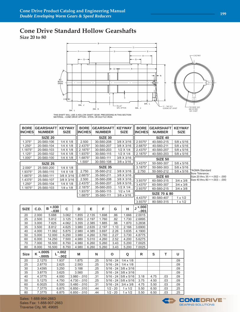
THIS SHAFT WILL USE A HOLLOW SHAFT GEAR. PRECEEDING IN THIS SECTIONMATERIAL - CONE DRIVE OPTION - STEEL OR DUCTILE IRON.
60°BOTHENDS
B
C
EDF
H
G
S R
M
N
U
DIA. L
DIA. J
DIA. K
T
DIA. J
DIA. L
G
Cone Drive Standard Hollow Gearshafts
*AGMA Standard Bore Tolerance: Size 20 thru 35 = +.002 – .000Size 40 thru 80 = +.003 – .000
BOREINCHES
GEARSHAFTNUMBER
KEYWAYSIZE
SIZE 201.375* 20-S60-106 1/4 X 1/81.250* 20-S60-104 1/4 X 1/8
1.1875* 20-S60-103 1/4 X 1/81.125* 20-S60-102 1/4 X 1/81.000* 20-S60-100 1/4 X 1/8
SIZE 252.000* 25-S60-200 1/4 X 1/8
1.9375* 25-S60-115 1/4 X 1/81.6875* 25-S60-111 3/8 X 3/161.4375* 25-S60-107 3/8 X 3/161.250* 25-S60-104 1/4 X 1/8
1.1875* 25-S60-103 1/4 x 1/8
BOREINCHES
GEARSHAFTNUMBER
KEYWAYSIZE
SIZE 302.500 30-S60-208 3/8 X 3/16
2.4375* 30-S60-207 3/8 X 3/162.1875* 30-S60-203 1/2 X 1/41.9375* 30-S60-115 1/2 X 1/41.6875* 30-S60-111 3/8 X 3/161.500* 30-S60-108 3/8 x 3/16
SIZE 352.750 35-S60-212 3/8 X 3/16
2.6875* 35-S60-211 3/8 X 3/162.500 35-S60-208 3/8 X 3/16
2.4375* 35-S60-207 5/8 X 5/162.1875* 35-S60-203 1/2 X 1/41.9375* 35-S60-115 1/2 x 1/41.6875* 35-S60-111 3/8 x 3/16
BOREINCHES
GEARSHAFTNUMBER
KEYWAYSIZE
SIZE 402.9375* 40-S60-215 5/8 x 5/162.6875* 40-S60-211 5/8 x 5/162.4375* 40-S60-207 5/8 x 5/162.1875* 40-S60-203 5/8 x 5/16
SIZE 503.4375* 50-S60-307 5/8 x 5/163.1875* 50-S60-303 5/8 x 5/162.750 50-S60-212 5/8 x 5/16
SIZE 603.9375* 60-S60-315 3/4 x 3/83.4375* 60-S60-307 3/4 x 3/82.9375* 60-S60-215 3/4 x 3/8
SIZE 70 & 804.4375* 80-S60-407 1 x 1/23.9375* 80-S60-315 1 x 1/2
SIZE C.D. B +.030 -.030 C D E F G H J +.000
-.00120 2.000 5.688 3.062 1.855 2.135 1.698 .86 1.666 2.001525 2.500 5.812 3.125 1.855 2.197 1.760 .82 1.730 2.689530 3.000 7.625 4.062 3.355 2.385 1.885 .98 1.870 3.283835 3.500 8.812 4.625 3.980 2.635 2.197 1.10 2.166 3.690040 4.000 11.062 5.875 2.980 4.385 3.697 2.26 3.635 4.190050 5.000 12.000 6.250 3.980 4.260 3.760 2.27 3.730 4.877560 6.000 14.250 7.500 4.980 5.010 4.260 2.52 4.200 5.627570 7.000 16.500 8.750 4.980 6.260 5.260 3.43 5.200 7.002580 8.000 16.500 8.750 4.980 6.260 5.260 3.43 5.200 7.0025
Size K +.0005 -.0005 L+.002
-.002 M N O Q R S T U20 2.1270 1.937 1.875 .25 5/16 - 24 1/4 x 1/8 .0925 2.8770 2.625 2.593 .25 5/16 - 24 1/4 x 1/8 .0930 3.4395 3.250 3.188 .25 5/16 - 24 3/8 x 3/16 .0935 3.8775 3.625 3.560 .25 5/16 - 24 3/8 x 3/16 .0940 4.3775 4.000 3.980 - .010 .31 5/16 - 24 5/8 x 5/16 3.18 4.75 .03 .0950 5.1275 4.750 4.730 - .010 .25 5/16 - 24 5/8 x 5/16 3.75 4.50 .03 .0960 6.0025 5.500 5.480 - .010 .31 5/16 - 24 3/4 x 3/8 4.75 5.50 .03 .0970 7.3775 6.875 6.850 - .010 .44 1/2 - 20 1 x 1/2 5.50 6.50 .03 .2580 7.3775 6.875 6.850 - .010 .44 1/2 - 20 1 x 1/2 5.50 6.50 .03 .25
Size 20 to 80
TM
Cone Drive Product Catalog and Engineering ManualDouble Enveloping Worm Gears & Speed Reducers 199
Sales: 1-888-994-2663Sales Fax: 1-888-907-2663Traverse City, MI. 49685
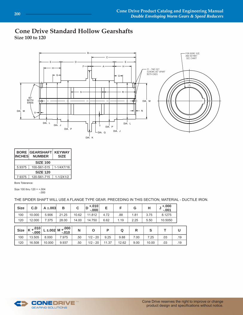
Cone Drive Standard Hollow Gearshafts
60°BOTHENDS
B
C
ED
F H
G
S R
DIA. M
NU
DIA. LDIA. J
DIA. PT
DIA. J
DIA. L
G
DIA. M
DIA. K
DIA. P
DIA. Q
E
AH
Size C.D A ±.003 B C D +.010 -.000 E F G H J +.000
-.001100 10.000 5.906 21.25 10.62 11.812 4.72 .88 1.81 3.75 8.1275
120 12.000 7.375 28.00 14.00 14.750 6.62 1.19 2.25 5.50 10.5050
Size K +.010 -.000 L ±.002 M +.000
-.010 N O P Q R S T U
100 13.505 8.000 7.975 .50 1/2 - 20 9.25 9.88 7.00 7.25 .03 .19
120 16.508 10.000 9.937 .50 1/2 - 20 11.37 12.62 9.00 10.00 .03 .19
THE SPIDER SHAFT WILL USE A FLANGE TYPE GEAR. PRECEDING IN THIS SECTION, MATERIAL - DUCTILE IRON.
Bore Tolerance:
Size 100 thru 120 = +.004 -.000
BOREINCHES
GEARSHAFTNUMBER
KEYWAYSIZE
SIZE 1005.9375 100-S61-515 1-1/4X7/16
SIZE 1207.9375 120-S61-715 1-1/2X1/2
Size 100 to 120
Cone Drive Product Catalog and Engineering ManualDouble Enveloping Worm Gears & Speed Reducers200
Cone Drive reserves the right to improve or change product design and specifi cations without notice.
TM
Cone Drive part numbers are shown in bold print. Contact Cone Drive for additional gearshaft dimensions when required.
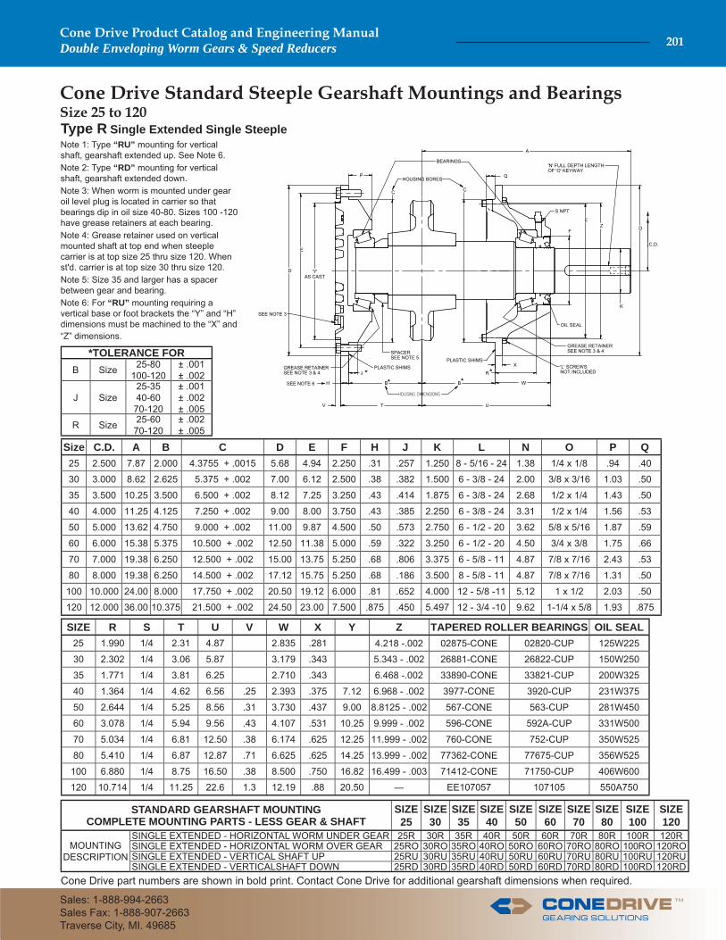
Cone Drive Standard Steeple Gearshaft Mountings and Bearings
Note 1: Type “RU” mounting for vertical shaft, gearshaft extended up. See Note 6.Note 2: Type “RD” mounting for vertical shaft, gearshaft extended down.Note 3: When worm is mounted under gear oil level plug is located in carrier so that bearings dip in oil size 40-80. Sizes 100 -120 have grease retainers at each bearing.Note 4: Grease retainer used on vertical mounted shaft at top end when steeple carrier is at top size 25 thru size 120. When st'd. carrier is at top size 30 thru size 120.Note 5: Size 35 and larger has a spacer between gear and bearing.Note 6: For “RU” mounting requiring a vertical base or foot brackets the “Y” and “H” dimensions must be machined to the “X” and “Z” dimensions.
Type R Single Extended Single Steeple
W
A
'Y' AS CAST
Q
X
Z
C C
E
B
E
B
D
DF
P
K
C.D.
'N' FULL DEPTH LENGTHOF 'O' KEYWAY
'L' SCREWSNOT INCLUDED
BEARINGS
HOUSING BORES
PLASTIC SHIMSPLASTIC SHIMS
SPACERSEE NOTE 5
GREASE RETAINER SEE NOTE 3 & 4
OIL SEAL
T U
H
V
R***
GREASE RETAINER SEE NOTE 3 & 4
SEE NOTE 6
J *
S NPT
SEE NOTE 3
Size C.D. A B C D E F H J K L N O P Q25 2.500 7.87 2.000 4.3755 + .0015 5.68 4.94 2.250 .31 .257 1.250 8 - 5/16 - 24 1.38 1/4 x 1/8 .94 .40
30 3.000 8.62 2.625 5.375 + .002 7.00 6.12 2.500 .38 .382 1.500 6 - 3/8 - 24 2.00 3/8 x 3/16 1.03 .50
35 3.500 10.25 3.500 6.500 + .002 8.12 7.25 3.250 .43 .414 1.875 6 - 3/8 - 24 2.68 1/2 x 1/4 1.43 .50
40 4.000 11.25 4.125 7.250 + .002 9.00 8.00 3.750 .43 .385 2.250 6 - 3/8 - 24 3.31 1/2 x 1/4 1.56 .53
50 5.000 13.62 4.750 9.000 + .002 11.00 9.87 4.500 .50 .573 2.750 6 - 1/2 - 20 3.62 5/8 x 5/16 1.87 .59
60 6.000 15.38 5.375 10.500 + .002 12.50 11.38 5.000 .59 .322 3.250 6 - 1/2 - 20 4.50 3/4 x 3/8 1.75 .66
70 7.000 19.38 6.250 12.500 + .002 15.00 13.75 5.250 .68 .806 3.375 6 - 5/8 - 11 4.87 7/8 x 7/16 2.43 .53
80 8.000 19.38 6.250 14.500 + .002 17.12 15.75 5.250 .68 .186 3.500 8 - 5/8 - 11 4.87 7/8 x 7/16 1.31 .50
100 10.000 24.00 8.000 17.750 + .002 20.50 19.12 6.000 .81 .652 4.000 12 - 5/8 -11 5.12 1 x 1/2 2.03 .50
120 12.000 36.00 10.375 21.500 + .002 24.50 23.00 7.500 .875 .450 5.497 12 - 3/4 -10 9.62 1-1/4 x 5/8 1.93 .875
SIZE R S T U V W X Y Z TAPERED ROLLER BEARINGS OIL SEAL25 1.990 1/4 2.31 4.87 2.835 .281 4.218 -.002 02875-CONE 02820-CUP 125W225
30 2.302 1/4 3.06 5.87 3.179 .343 5.343 - .002 26881-CONE 26822-CUP 150W250
35 1.771 1/4 3.81 6.25 2.710 .343 6.468 -.002 33890-CONE 33821-CUP 200W325
40 1.364 1/4 4.62 6.56 .25 2.393 .375 7.12 6.968 - .002 3977-CONE 3920-CUP 231W375
50 2.644 1/4 5.25 8.56 .31 3.730 .437 9.00 8.8125 - .002 567-CONE 563-CUP 281W450
60 3.078 1/4 5.94 9.56 .43 4.107 .531 10.25 9.999 - .002 596-CONE 592A-CUP 331W500
70 5.034 1/4 6.81 12.50 .38 6.174 .625 12.25 11.999 - .002 760-CONE 752-CUP 350W525
80 5.410 1/4 6.87 12.87 .71 6.625 .625 14.25 13.999 - .002 77362-CONE 77675-CUP 356W525
100 6.880 1/4 8.75 16.50 .38 8.500 .750 16.82 16.499 - .003 71412-CONE 71750-CUP 406W600
120 10.714 1/4 11.25 22.6 1.3 12.19 .88 20.50 — EE107057 107105 550A750
STANDARD GEARSHAFT MOUNTINGCOMPLETE MOUNTING PARTS - LESS GEAR & SHAFT
SIZE25
SIZE30
SIZE35
SIZE40
SIZE50
SIZE60
SIZE70
SIZE80
SIZE100
SIZE120
MOUNTING DESCRIPTION
SINGLE EXTENDED - HORIZONTAL WORM UNDER GEAR 25R 30R 35R 40R 50R 60R 70R 80R 100R 120RSINGLE EXTENDED - HORIZONTAL WORM OVER GEAR 25RO 30RO 35RO 40RO 50RO 60RO 70RO 80RO 100RO 120ROSINGLE EXTENDED - VERTICAL SHAFT UP 25RU 30RU 35RU 40RU 50RU 60RU 70RU 80RU 100RU 120RUSINGLE EXTENDED - VERTICALSHAFT DOWN 25RD 30RD 35RD 40RD 50RD 60RD 70RD 80RD 100RD 120RD
*TOLERANCE FORB Size 25-80
100-120± .001± .002
J Size25-3540-60
70-120
± .001± .002± .005
R Size 25-6070-120
± .002± .005
Size 25 to 120
TM
Cone Drive Product Catalog and Engineering ManualDouble Enveloping Worm Gears & Speed Reducers 201
Sales: 1-888-994-2663Sales Fax: 1-888-907-2663Traverse City, MI. 49685
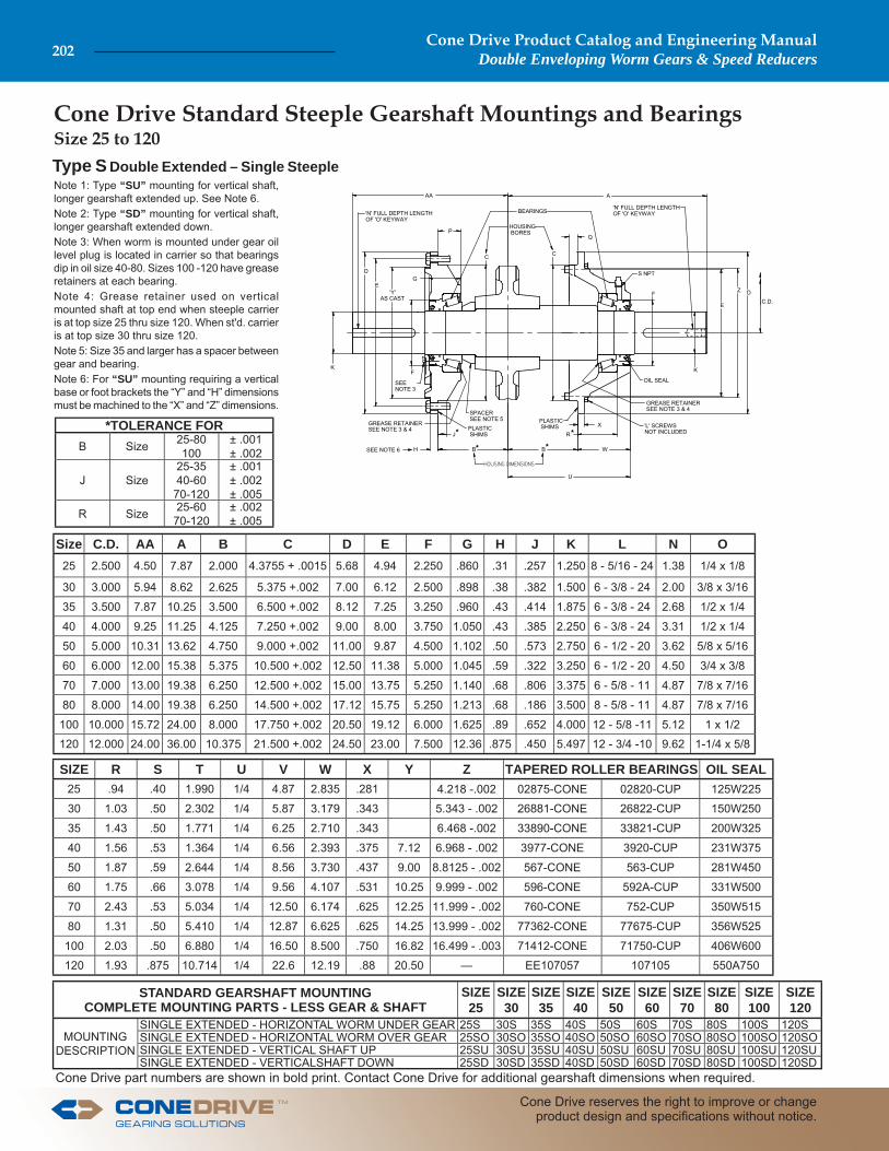
Cone Drive Standard Steeple Gearshaft Mountings and Bearings Size 25 to 120
Cone Drive part numbers are shown in bold print. Contact Cone Drive for additional gearshaft dimensions when required.
W
A
'Y' AS CAST
Q
X
Z
C C
E
B
E
B
D
DF
P
K
C.D.
'N' FULL DEPTH LENGTHOF 'O' KEYWAY
'L' SCREWSNOT INCLUDED
BEARINGS
HOUSING BORES
PLASTIC SHIMS
PLASTIC SHIMS
SPACERSEE NOTE 5
GREASE RETAINER SEE NOTE 3 & 4
OIL SEAL
U
H
AA
R*
**
GREASE RETAINER SEE NOTE 3 & 4
SEE NOTE 6
J*
S NPT
FK
SEE NOTE 3
'N' FULL DEPTH LENGTHOF 'O' KEYWAY
G
Type S Double Extended – Single SteepleNote 1: Type “SU” mounting for vertical shaft, longer gearshaft extended up. See Note 6.Note 2: Type “SD” mounting for vertical shaft, longer gearshaft extended down.Note 3: When worm is mounted under gear oil level plug is located in carrier so that bearings dip in oil size 40-80. Sizes 100 -120 have grease retainers at each bearing.Note 4: Grease retainer used on vertical mounted shaft at top end when steeple carrier is at top size 25 thru size 120. When st'd. carrier is at top size 30 thru size 120.Note 5: Size 35 and larger has a spacer between gear and bearing.Note 6: For “SU” mounting requiring a vertical base or foot brackets the “Y” and “H” dimensions must be machined to the “X” and “Z” dimensions.
Size C.D. AA A B C D E F G H J K L N O25 2.500 4.50 7.87 2.000 4.3755 + .0015 5.68 4.94 2.250 .860 .31 .257 1.250 8 - 5/16 - 24 1.38 1/4 x 1/8
30 3.000 5.94 8.62 2.625 5.375 +.002 7.00 6.12 2.500 .898 .38 .382 1.500 6 - 3/8 - 24 2.00 3/8 x 3/16
35 3.500 7.87 10.25 3.500 6.500 +.002 8.12 7.25 3.250 .960 .43 .414 1.875 6 - 3/8 - 24 2.68 1/2 x 1/4
40 4.000 9.25 11.25 4.125 7.250 +.002 9.00 8.00 3.750 1.050 .43 .385 2.250 6 - 3/8 - 24 3.31 1/2 x 1/4
50 5.000 10.31 13.62 4.750 9.000 +.002 11.00 9.87 4.500 1.102 .50 .573 2.750 6 - 1/2 - 20 3.62 5/8 x 5/16
60 6.000 12.00 15.38 5.375 10.500 +.002 12.50 11.38 5.000 1.045 .59 .322 3.250 6 - 1/2 - 20 4.50 3/4 x 3/8
70 7.000 13.00 19.38 6.250 12.500 +.002 15.00 13.75 5.250 1.140 .68 .806 3.375 6 - 5/8 - 11 4.87 7/8 x 7/16
80 8.000 14.00 19.38 6.250 14.500 +.002 17.12 15.75 5.250 1.213 .68 .186 3.500 8 - 5/8 - 11 4.87 7/8 x 7/16
100 10.000 15.72 24.00 8.000 17.750 +.002 20.50 19.12 6.000 1.625 .89 .652 4.000 12 - 5/8 -11 5.12 1 x 1/2
120 12.000 24.00 36.00 10.375 21.500 +.002 24.50 23.00 7.500 12.36 .875 .450 5.497 12 - 3/4 -10 9.62 1-1/4 x 5/8
SIZE R S T U V W X Y Z TAPERED ROLLER BEARINGS OIL SEAL25 .94 .40 1.990 1/4 4.87 2.835 .281 4.218 -.002 02875-CONE 02820-CUP 125W225
30 1.03 .50 2.302 1/4 5.87 3.179 .343 5.343 - .002 26881-CONE 26822-CUP 150W250
35 1.43 .50 1.771 1/4 6.25 2.710 .343 6.468 -.002 33890-CONE 33821-CUP 200W325
40 1.56 .53 1.364 1/4 6.56 2.393 .375 7.12 6.968 - .002 3977-CONE 3920-CUP 231W375
50 1.87 .59 2.644 1/4 8.56 3.730 .437 9.00 8.8125 - .002 567-CONE 563-CUP 281W450
60 1.75 .66 3.078 1/4 9.56 4.107 .531 10.25 9.999 - .002 596-CONE 592A-CUP 331W500
70 2.43 .53 5.034 1/4 12.50 6.174 .625 12.25 11.999 - .002 760-CONE 752-CUP 350W515
80 1.31 .50 5.410 1/4 12.87 6.625 .625 14.25 13.999 - .002 77362-CONE 77675-CUP 356W525
100 2.03 .50 6.880 1/4 16.50 8.500 .750 16.82 16.499 - .003 71412-CONE 71750-CUP 406W600
120 1.93 .875 10.714 1/4 22.6 12.19 .88 20.50 — EE107057 107105 550A750
STANDARD GEARSHAFT MOUNTINGCOMPLETE MOUNTING PARTS - LESS GEAR & SHAFT
SIZE25
SIZE30
SIZE35
SIZE40
SIZE50
SIZE60
SIZE70
SIZE80
SIZE100
SIZE120
MOUNTING DESCRIPTION
SINGLE EXTENDED - HORIZONTAL WORM UNDER GEAR 25S 30S 35S 40S 50S 60S 70S 80S 100S 120SSINGLE EXTENDED - HORIZONTAL WORM OVER GEAR 25SO 30SO 35SO 40SO 50SO 60SO 70SO 80SO 100SO 120SOSINGLE EXTENDED - VERTICAL SHAFT UP 25SU 30SU 35SU 40SU 50SU 60SU 70SU 80SU 100SU 120SUSINGLE EXTENDED - VERTICALSHAFT DOWN 25SD 30SD 35SD 40SD 50SD 60SD 70SD 80SD 100SD 120SD
*TOLERANCE FORB Size 25-80
100± .001± .002
J Size25-3540-60
70-120
± .001± .002± .005
R Size 25-6070-120
± .002± .005
Cone Drive Product Catalog and Engineering ManualDouble Enveloping Worm Gears & Speed Reducers202
Cone Drive reserves the right to improve or change product design and specifi cations without notice.
TM
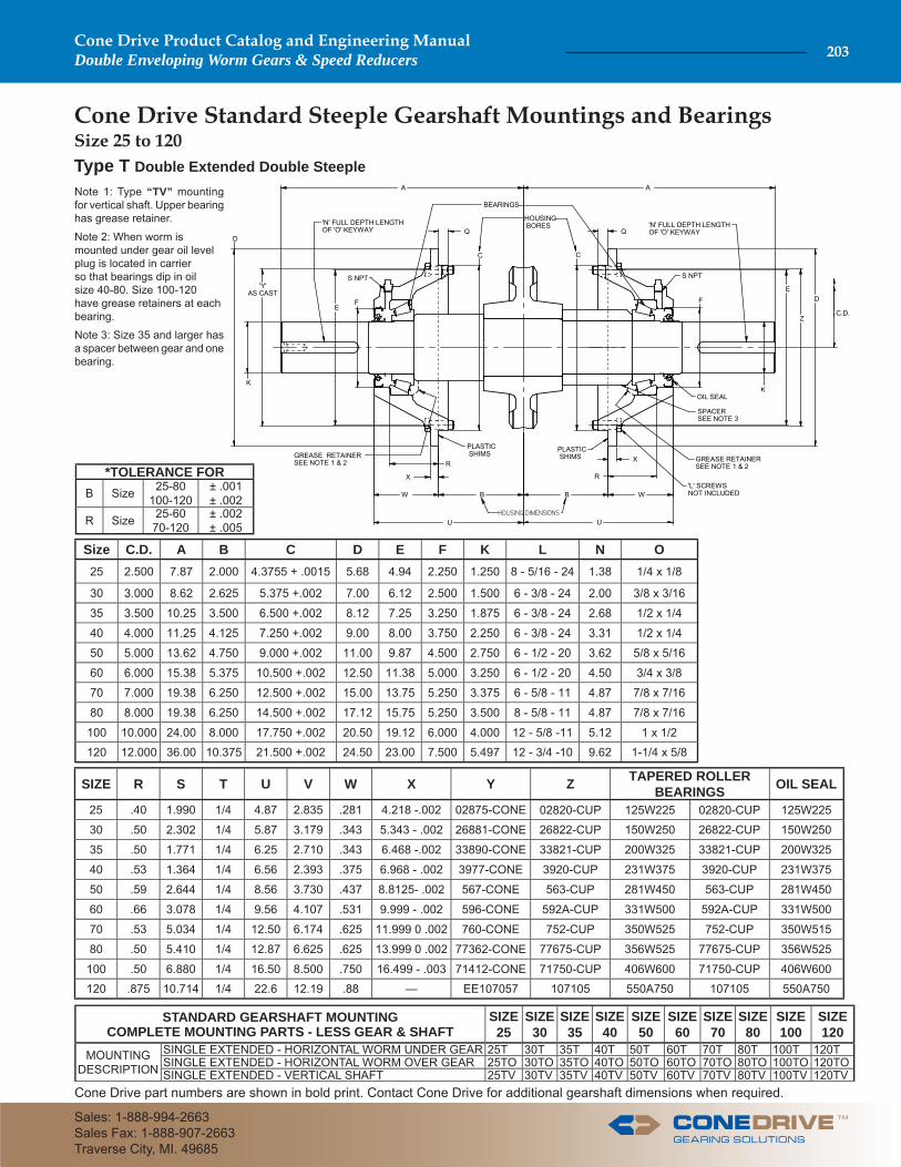
W
A
'Y' AS CAST
Q
X
Z
C C
E
B
E
B
DF
Q
K
C.D.
'N' FULL DEPTH LENGTHOF 'O' KEYWAY
'L' SCREWSNOT INCLUDED
BEARINGS
HOUSING BORES
PLASTIC SHIMS PLASTIC
SHIMS
SPACERSEE NOTE 3
OIL SEAL
U U
X
A
R
GREASE RETAINER SEE NOTE 1 & 2 R
S NPT
D
'N' FULL DEPTH LENGTHOF 'O' KEYWAY
F
K
W
GREASE RETAINER SEE NOTE 1 & 2
S NPT
Cone Drive Standard Steeple Gearshaft Mountings and BearingsSize 25 to 120
Cone Drive part numbers are shown in bold print. Contact Cone Drive for additional gearshaft dimensions when required.
Type T Double Extended Double Steeple
Size C.D. A B C D E F K L N O25 2.500 7.87 2.000 4.3755 + .0015 5.68 4.94 2.250 1.250 8 - 5/16 - 24 1.38 1/4 x 1/8
30 3.000 8.62 2.625 5.375 +.002 7.00 6.12 2.500 1.500 6 - 3/8 - 24 2.00 3/8 x 3/16
35 3.500 10.25 3.500 6.500 +.002 8.12 7.25 3.250 1.875 6 - 3/8 - 24 2.68 1/2 x 1/4
40 4.000 11.25 4.125 7.250 +.002 9.00 8.00 3.750 2.250 6 - 3/8 - 24 3.31 1/2 x 1/4
50 5.000 13.62 4.750 9.000 +.002 11.00 9.87 4.500 2.750 6 - 1/2 - 20 3.62 5/8 x 5/16
60 6.000 15.38 5.375 10.500 +.002 12.50 11.38 5.000 3.250 6 - 1/2 - 20 4.50 3/4 x 3/8
70 7.000 19.38 6.250 12.500 +.002 15.00 13.75 5.250 3.375 6 - 5/8 - 11 4.87 7/8 x 7/16
80 8.000 19.38 6.250 14.500 +.002 17.12 15.75 5.250 3.500 8 - 5/8 - 11 4.87 7/8 x 7/16
100 10.000 24.00 8.000 17.750 +.002 20.50 19.12 6.000 4.000 12 - 5/8 -11 5.12 1 x 1/2
120 12.000 36.00 10.375 21.500 +.002 24.50 23.00 7.500 5.497 12 - 3/4 -10 9.62 1-1/4 x 5/8
SIZE R S T U V W X Y Z TAPERED ROLLER BEARINGS OIL SEAL
25 .40 1.990 1/4 4.87 2.835 .281 4.218 -.002 02875-CONE 02820-CUP 125W225 02820-CUP 125W225
30 .50 2.302 1/4 5.87 3.179 .343 5.343 - .002 26881-CONE 26822-CUP 150W250 26822-CUP 150W250
35 .50 1.771 1/4 6.25 2.710 .343 6.468 -.002 33890-CONE 33821-CUP 200W325 33821-CUP 200W325
40 .53 1.364 1/4 6.56 2.393 .375 6.968 - .002 3977-CONE 3920-CUP 231W375 3920-CUP 231W375
50 .59 2.644 1/4 8.56 3.730 .437 8.8125- .002 567-CONE 563-CUP 281W450 563-CUP 281W450
60 .66 3.078 1/4 9.56 4.107 .531 9.999 - .002 596-CONE 592A-CUP 331W500 592A-CUP 331W500
70 .53 5.034 1/4 12.50 6.174 .625 11.999 0 .002 760-CONE 752-CUP 350W525 752-CUP 350W515
80 .50 5.410 1/4 12.87 6.625 .625 13.999 0 .002 77362-CONE 77675-CUP 356W525 77675-CUP 356W525
100 .50 6.880 1/4 16.50 8.500 .750 16.499 - .003 71412-CONE 71750-CUP 406W600 71750-CUP 406W600
120 .875 10.714 1/4 22.6 12.19 .88 — EE107057 107105 550A750 107105 550A750
STANDARD GEARSHAFT MOUNTINGCOMPLETE MOUNTING PARTS - LESS GEAR & SHAFT
SIZE25
SIZE30
SIZE35
SIZE40
SIZE50
SIZE60
SIZE70
SIZE80
SIZE100
SIZE120
MOUNTING DESCRIPTION
SINGLE EXTENDED - HORIZONTAL WORM UNDER GEAR 25T 30T 35T 40T 50T 60T 70T 80T 100T 120TSINGLE EXTENDED - HORIZONTAL WORM OVER GEAR 25TO 30TO 35TO 40TO 50TO 60TO 70TO 80TO 100TO 120TOSINGLE EXTENDED - VERTICAL SHAFT 25TV 30TV 35TV 40TV 50TV 60TV 70TV 80TV 100TV 120TV
*TOLERANCE FORB Size 25-80
100-120± .001± .002
R Size 25-6070-120
± .002± .005
Note 1: Type “TV” mounting for vertical shaft. Upper bearing has grease retainer.
Note 2: When worm is mounted under gear oil level plug is located in carrier so that bearings dip in oil size 40-80. Size 100-120 have grease retainers at each bearing.
Note 3: Size 35 and larger has a spacer between gear and one bearing.
TM
Cone Drive Product Catalog and Engineering ManualDouble Enveloping Worm Gears & Speed Reducers 203
Sales: 1-888-994-2663Sales Fax: 1-888-907-2663Traverse City, MI. 49685
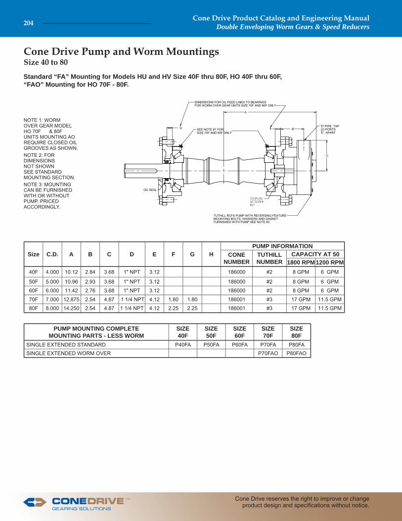
Cone Drive Pump and Worm Mountings
Standard “FA” Mounting for Models HU and HV Size 40F thru 80F, HO 40F thru 60F, “FAO” Mounting for HO 70F - 80F.
A
G
C
TUTHILL RCFA PUMP WITH REVERSING FEATUREMOUNTING BOLTS, WASHERS AND GASKETFURNISHED WITH PUMP SEE NOTE #3
SEE NOTE #1 FORSIZE 70F AND 80F ONLY
DIMENSIONS FOR OIL FEED LINES TO BEARINGSFOR WORM OVER GEAR UNITS SIZE 70F AND 80F ONLY
OIL SEAL
BF'D' PIPE TAP(2) PORTS'E' APART
NOTE 1: WORM OVER GEAR MODEL HO 70F & 80F UNITS MOUNTING AO REQUIRE CLOSED OIL GROOVES AS SHOWN.NOTE 2: FOR DIMENSIONS NOT SHOWN SEE STANDARD MOUNTING SECTION.NOTE 3: MOUNTING CAN BE FURNISHED WITH OR WITHOUT PUMP, PRICED ACCORDINGLY.
Size C.D. A B C D E F G HPUMP INFORMATION
CONE NUMBER
TUTHILL NUMBER
CAPACITY AT 501800 RPM 1200 RPM
40F 4.000 10.12 2.84 3.68 1" NPT 3.12 186000 #2 8 GPM 6 GPM
50F 5.000 10.96 2.93 3.68 1" NPT 3.12 186000 #2 8 GPM 6 GPM
60F 6.000 11.42 2.76 3.68 1" NPT 3.12 186000 #2 8 GPM 6 GPM
70F 7.000 12.875 2.54 4.87 1 1/4 NPT 4.12 1.80 1.80 186001 #3 17 GPM 11.5 GPM
80F 8.000 14.250 2.54 4.87 1 1/4 NPT 4.12 2.25 2.25 186001 #3 17 GPM 11.5 GPM
PUMP MOUNTING COMPLETEMOUNTING PARTS - LESS WORM
SIZE40F
SIZE50F
SIZE60F
SIZE70F
SIZE80F
SINGLE EXTENDED STANDARD P40FA P50FA P60FA P70FA P80FASINGLE EXTENDED WORM OVER P70FAO P80FAO
Size 40 to 80
Cone Drive Product Catalog and Engineering ManualDouble Enveloping Worm Gears & Speed Reducers204
Cone Drive reserves the right to improve or change product design and specifi cations without notice.
TM
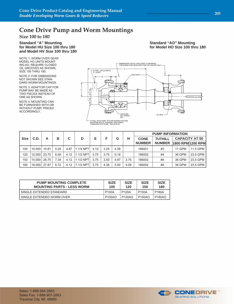
Cone Drive Pump and Worm Mountings Size 100 to 180
B
A
COUPLINGSET SCREWKEY
OIL SEAL
GF
TUTHILL RCFA PUMP WITH REVERSING FEATUREMOUNTING BOLTS, WASHERS AND GASKETFURNISHED WITH PUMP. SEE NOTE #4
DIMENSIONS FOR OIL FEED LINES TO BEARINGSFOR WORM OVER GEAR UNITS SIZE 70F AND 80F ONLY
'D' PIPE TAP (2) PORTS'E' APART
SEE NOTE 1
C
NOTE 1: WORM OVER GEAR MODEL HO UNITS MOUNT-ING AO, REQUIRE CLOSED OIL GROOVES AS SHOWN, SIZE 100 THRU 180.NOTE 2: FOR DIMENSIONS NOT SHOWN SEE STAN-DARD WORM MOUNTINGS.NOTE 3: ADAPTOR CAP FOR PUMP MAY BE MADE AS TWO PIECES INSTEAD OF ONE AS SHOWN.NOTE 4: MOUNTING CAN BE FURNISHED WITH OR WITHOUT PUMP, PRICED ACCORDINGLY.
Standard “A” Mountingfor Model HU Size 100 thru 180and Model HV Size 100 thru 180
Standard “AO” Mountingfor Model HO Size 100 thru 180
Size C.D. A B C D E F G HPUMP INFORMATION
CONE NUMBER
TUTHILL NUMBER
CAPACITY AT 501800 RPM 1200 RPM
100 10.000 19.81 5.25 4.87 1 1/4 NPT 4.12 3.25 4.38 186001 #3 17 GPM 11.5 GPM
120 12.000 23.75 6.59 4.12 1 1/2 NPT 3.75 3.75 5.19 186002 #4 36 GPM 23.5 GPM
150 15.000 26.75 7.34 4.12 1 1/2 NPT 3.75 3.50 4.87 3.75 186002 #4 36 GPM 23.5 GPM
180 18.000 27.87 6.72 4.12 1 1/2 NPT 3.75 4.38 5.50 4.09 186002 #4 36 GPM 23.5 GPM
PUMP MOUNTING COMPLETEMOUNTING PARTS - LESS WORM
SIZE100
SIZE120
SIZE150
SIZE180
SINGLE EXTENDED STANDARD P100A P120A P150A P180ASINGLE EXTENDED WORM OVER P100AO P120AO P150AO P180AO
TM
Cone Drive Product Catalog and Engineering ManualDouble Enveloping Worm Gears & Speed Reducers 205
Sales: 1-888-994-2663Sales Fax: 1-888-907-2663Traverse City, MI. 49685
Model HP Specials
Cone Drive Operations, Inc240 E. 12th Street,Traverse City, MI. 49685
Sales: 1-888-994-2663
Sales Fax: 1-888-907-2663
Cone Drive Family of Products
AccuDrive Gearsets
TM
22830


![[3] involuteΣ Worm Gear Design System · [3] involuteΣ Worm Gear Design System Fig. 3.1 involuteΣ Worm Gear Design System 3.1 Introduction The involuteΣ Worm Gear Design System](https://static.documents.pub/doc/80x56/5eadff0184c9a55408434a64/3-involute-worm-gear-design-3-involute-worm-gear-design-system-fig-31.jpg)

![KISSsoft 03/2018 Tutorial 16 · 1.2 Starting the drive element of worm gear with enveloping ... coefficient is 0.2. ... Profile shift coefficient [x-worm] 0.0000](https://static.documents.pub/doc/80x56/5b64d7c97f8b9af84b8dc954/kisssoft-032018-tutorial-16-12-starting-the-drive-element-of-worm-gear-with.jpg)


