11
Double Pendulum PowerMethod for Extracting AC Power from a Mechanical Oscillator
Anon Ymous, M.Sc. M.E.
21-10-13
1 Introduction
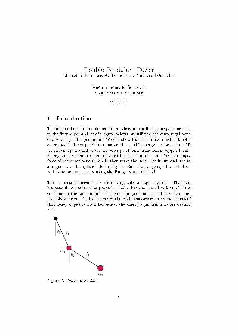
The idea is that of a double pendulum where an oscillating torque is createdin the �xture point (black in �gure below) by utilizing the centrifugal forceof a rotating outer pendulum. We will show that this force transfers kineticenergy to the inner pendulum mass and that this energy can be useful. Af-ter the energy needed to set the outer pendulum in motion is supplied, onlyenergy to overcome friction is needed to keep it in motion. The centrifugalforce of the outer pendulum will then make the inner pendulum oscillate ata frequency and amplitude de�ned by the Euler Lagrange equations that wewill examine numerically using the Runge Kutta method.
This is possible because we are dealing with an open system. The dou-ble pendulum needs to be properly �xed otherwise the vibrations will justcontinue to the surroundings or being damped and turned into heat andpossibly wear out the �xture materials. So in that sense a tiny movement ofthat heavy object is the other side of the energy equilibrium we are dealingwith.
Figure 1: double pendulum
1

AnonYmousEngineering
2 The Physics
First consider the well known Euler Lagrange equations for the double pen-dulum.
(m1+m2)l1θ̈1+m2l2θ̈2cos(θ1−θ2)+m2l2θ̇22sin(θ1−θ2)+g(m1+m2)sinθ1 = 0
(1)
m2l2θ̈2 +m2l1θ̈1cos(θ1 − θ2) −m2l1θ̇21sin(θ1 − θ2) +m2gsinθ2 = 0 (2)
To be able to solve these equations using the Runge Kutta method we elab-orate the equations for the angular accelerations respectively; θ̈1 and θ̈2.
θ̈1 =−g(2m1 +m2)sinθ1 −m2gsin(θ1 − 2θ2)
l1(2m1 +m2 −m2cos(2θ1 − 2θ2))
− 2sin(θ1 − θ2)m2(θ̇22l2 + θ̇21l1cos(θ1 − θ2))
l1(2m1 +m2 −m2cos(2θ1 − 2θ2))
(3)
θ̈2 =2sin(θ1 − θ2)(θ̇
21l1(m1 +m2) + g(m1 +m2)cosθ1 + θ̇22l2m2cos(θ1 − θ2))
l2(2m1 +m2 −m2cos(2θ1 − 2θ2))(4)
Finally we set up the equation for the power needed to either increase (ac-celerate) or decrease (decelerate) the speed (kinetic energy) of the innerpendulum mass (m1) with the pendulum arm (l1). This is the power thatwe propose could be partially used for generating useful energy.
Pm1 = m1l21θ̈1θ̇1 (5)
Figure 2: Power from Double Pendulum as a function of time
2

AnonYmousEngineering
The Runge Kutta method is used to solving the equation numerically. Weuse the following input data: m1 = 1kg, m2 = 1kg, l1 = 0.1m, l2 = 0.1m,θ̇2 = 100 rad/s (i.e. the initial speed of rotation of the outer pendulumis ≈ 16 Hz which equals an initial kinetic energy of Ek = 50J). We alsoassume rotation is in the horizontal level so that g = 0 and that there isno friction. As we can se in the graph the outer pendulum is constantlytransferring energy to the inner pendulum mass by use of centrifugal forceand vice versa. The result is that the the both the pendulum masses areconstantly accelerating/decelerating (oscillating), without any more inputof energy. And as Newton showed, accelerating mass is a manifestation ofenergy: Eenergy = mmassaaccelerationsdistance.
We thereby conclude that by setting the outer pendulum in motion with onlyEk = 50J we continuously either accelerate or decelerate the inner pendulummass with a power averaging P̄m1 ≈ 800W.
What we want to emphasize here, is that the fact that speed and accelerationis vector based but energy and power is scalar, makes it possible to makethis power useful. The schematic below outlines the principle of this line ofthought.
Figure 3: Double Pendulum with extra load (mass or electromagnetic)
What we do is to simply assume that the power used to accelerate or decel-erate the inner pendulum mass can be useful if we replace the mass with a
3

AnonYmousEngineering
generator. In theory all of the replaced inner pendulum mass could be useful,but in reality it is probably not the case because of design and constructionissues. Thus the distinction between the useful mload and mmachine in theschematic above.
The e�ciency of the generator concept could be described by the followingequation. As you can see a lightweight machinery of oscillating parts (mass)is always a good idea.
ηefficiency =mload
mload +mmachine(6)
3 The Case of the Milkovic Pendulum
Figure 4: Milkovic Pendulum (from http://www.pendulum-lever.com)
The Milkovic pendulum is a handdriven pendulum that could be used topump water. We've been examining a pendulum with our numerical modelwith the following input parameters: (2)m1 = 10 kg, (4)m2 = 10 kg, l1 = 0.5m, l2 = 0.3 m, θ2 = 2 rad (i.e. we lift the outer pendulum before we let it go,thereafter only a�ected by gravity). Lets have a look at the characteristicsof the movements of the pendulums in a fricionless environment.
4

AnonYmousEngineering
Figure 5: Pendulum movements, m1/massive lever (blue), m2/pendulum(red)
Lets assume that half of the power produced by the pendulum is used tomove the inner pendulum arm (i.e. "massive lever" machinery) and theother half is pumping water. Using Runge Kutte we calculate the prowerproduced as a function of time.
Pm1 = ηm1m1l21θ̈1θ̇1 (7)
Where ηm1 is the fraction of the mass that accounts for the usable power.In this case ηm1 = 0.5.
Figure 6: Pendulum power at 50% e�ciency averaging about 50W
5
AnonYmousEngineering
As we can se the pendulum is producing an average of about 50W with noinput except for the Ein = 42 J used to lift the pendulum initially (2 rad).It will keep swinging in a frictionless environment. It will however swing ina more or less unpredictable manner depending on the initial conditions. Aswe can see a considerable amount of the power will be delivered in the formof spikes.
Of course there are other issues about the construction. As an exampleMilkovic uses a much heavier machinery which will decrease e�ciency sinceso much power is used to move/oscillate the actual inner pendulum arm (mas-sive lever). We suspect Milkovic is doing this to control the output/inputmovements and amplitude. As an example; if the inner massive lever is in-creased to 100 kg (i.e. a tenfold increase) the output power will averageabout 27W at 50% e�ciency. A reduction of 46%, but with a more control-lable output amplitude.
The conclusion is that by pushing the pendulum to an equal angle at each os-cillation in order to overcome friction, it is possible to continuously produceoutput power much greater than the power needed to push the pendulumat low enough friction. The power will however be delivered in a somewhatunpredictable manner.
4 Generating Power
This report is however not so interested in handdriven pendulums as in thepossibility to build a generator that utilize the power in a automized mannerand generating electrical power at higher frequencies. We've already lookedat an example which rotates horizontally at 16 Hz producing an average of800W.
The interdependencies between the two pendulums continuously exchangingkinetic energy as they oscillate is complex. The two pendulums transfermomentum between themselves in both directions as described by the EulerLagrange equations earlier. If we try to force the outer pendulum into acertain speed or movement, we will no doubt disturb the inner pendulum asit transfer momentum back. Constant rotation of the outer pendulum willsimply not do.
At this point we continue by examine the motions and power resulting fromcertain initial values and leave the control problem for later.
Below we will have a look at a pendulum with the following input parame-
6

AnonYmousEngineering
ters: m1 = 1kg, m2 = 0.1kg, l1 = 0.2m, l2 = 0.1m, θ̇2 = 314 rad/s (initialspeed of rotation is 50 Hz).
Figure 7: Pendulum power from 50 Hz input, averaging about 1600 W
The most important fact about this pendulum is the considerable powergenerated from such a small device. A 1kg load on a 0.1kg pendulum withlevers of 0.2m and 0.1m respectively continuously generates 1600 W fromonly 49 J input. By now you probably realize why this is important. Itcould be possible to build really compact generators using this method if weovercome the engineering problems. For construction and material strengthpurposes we also note that the rotating pendulum applies an equally largestatic centrifugal force on the �xture in the direction of the inner pendulumarm. This engineering problem can be solved by using two synchronizedouter pendulums as described in the next section.
7

AnonYmousEngineering
5 Construction Schematic
Figure 8: Construction schematic
This is a simple schematic of a generator using what we've described. Onthe input side we have a motor attached to a driving cogwheel, which ro-tates the two unbalanced cogwheels (i.e. pendulums). These cogwheels aresynchronized so that all forces in the direction to and from the �xed axis iscancelled out at all times, which will reduce the stress on the �xture. Theunbalanced cogwheels are mounted on a frame that transfers momentum tothe generator.
• (1), (2) and (3) are cogwheels, where (2) and (3) are unbalanced. Theycan be considered pendulums.
• (4) is a motor/generator
• (2) and (3) are mounted on a "frame" (5) which rotates frictionless onthe axis (6).
• The motor/generator is �xed on cogwheel (1) so that it can either driveor receive energy/momentum to/from the system.
• The motor/generator is securely mounted on the �oor/surroundings.
We then suggest the following line of thought.
8
AnonYmousEngineering
1. The frame (5) with the cogwheels (2) and (3) is �xed so that it cannot rotate around axis (6).
2. The cogwheels are set in motion at the desired rotation speed with themotor. The frame is still �xed.
3. The motor drive is disconnected, now the motor acts as a generator.Still there is no load so the generator rotates frictionless.
4. The frame (5) �xation is disconnected sot that it now rotates/oscillatesfreely around axis (6) and transfers momentum to the generator (4).
5. Load is added on the generator.
If the machine was frictionless we would be able to extract power continu-ously. However this is of course not the case and a system for adding powerto overcome friction is needed. This is the tricky part because there is aconstant feedback of momentum coming from the pendulums (2) and (3) tothe driving cogwheel (1). This means that it will not be possible to add aconstant driving momentum on cogwheel (1) since this momentum simplywill work the machine in the wrong direction half of the time.
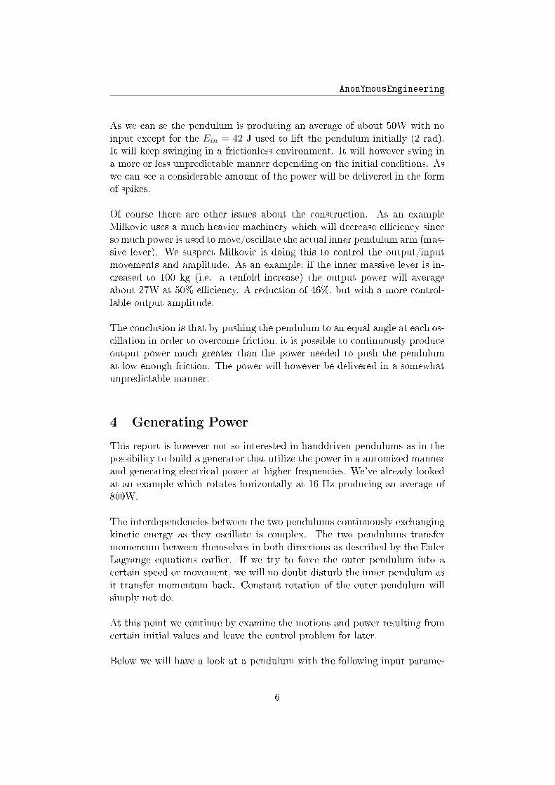
Therefore, we need to design a system that pulses the correct amount ofenergy/momentum to the driving cogwheel (1) with the right timing. Ob-viously this would be in the opposite direction of friction, i.e. always in thedirection of the current acceleration. Here is a graph showing the accelera-tions from the pendulums as a function of time.
Figure 9: Pendulum accelerations. M1 is blue and M2 is red
9
AnonYmousEngineering
From this graph we can conclude that it is possible to use the output fromthe inner pendulum, i.e. the generator output, as an input parameter forthe pulsed input power on the driving cogwheel. Our suggestion is to adda pulsed input power for maybe 1/10 of the time of the initial frequency ofrotation (i.e. 1/500 s), in the opposite direction of the initial rotation eachtime the output power is zero (0), which is twice per oscillation. It's actuallya simple case of resonance. The analogy for this is obvious; like pushing aplayground swing or for that matter, the Milkovic pendulum.
6 Building a Household Generator
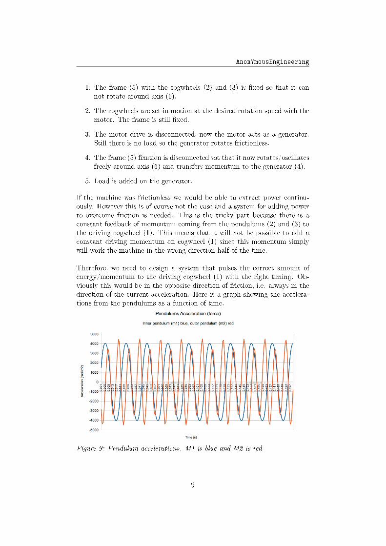
If we, as an example, want to build a household generator we could use two(or as many as we need) 0.1 kg pendulums with a radius of 0.1 m, mountedon a frame with the radius 0.2 m. The pendulums are set in initial rotation at50Hz. If the weight of the cogwheels and levers are assumed to be positionedat the cogwheel/pendulum center, and if this "machine weight" is 1 kg perpendulum at a e�ciency of 50%, the output will be approximately 3.2 kWof AC power. The output power distribution will look like in �gure 7 (buttwice the amplitude) and the electrical output something like in the �gure10 below.
Figure 10: Electical output schematic. Voltage (blue), current (red)
The equations for the output power is as follows. mMechLoad describes theproductive load/momentum, which is not the same as m1 that is the com-bined mass of the load and the unproductive weight of the cogwheels andframe (i.e. machine).
P (t)output = mMechLoadr2frameω
′AccOfFrameωSpeedOfFrame (8)
10

AnonYmousEngineering
From Kircho� we know that the voltage over a coil and a resistive load isdescribed as follows.
Li′ + iRload = 0 (9)
Consequently we get for the complete generator with electrical output.
P (t)output = Lii′ = i2Rload = mMechLoadr2frameω
′AccOfFrameωSpeedOfFrame
(10)As we can see, the current ioutput correlates directly with the speed of rota-tion ω and the voltage uoutput = Li′ correlates directly with the accelerationω′.
7 Conclusions
This document shows that it is possible to utilize the constant force actingthrough the arm of a pendulum in motion. The force is a function of speedof rotation (ω) but results in an acceleration of mass, i.e energy. The energywill manifest itself in the form of vibrations. We then make the connectionbetween these vibrations and the characteristics of AC current and realizethat it is exactly what we are looking for.The power extracted is a function of the frequency of rotation by the power ofthree (mr2ω′ω or Lii′). This also explains the extreme power of vibrations,for example in buildings, bridges and other constructions. Even minute im-balances in an engine gets the whole car to vibrate. And so on, and so on.
We also show the theory behind the dynamics and point out the fact thatit is an open system that does not violate any classic Newtonian laws butcan be described using a numerical solution (Runge Kutta) of the Euler La-grange equations of the double pendulum.
With this foundation of controlled oscillations directly converted into ACpower, simple motors can be built in any small village workshop everywherearound the globe. Help can be supplied with construction and motor designif needed. We emphasize the importance of design, and that the constructionfor transfer of power need to be lightweight i relation to the weight of thependulum.
As our hero Nikola Tesla famously said: "If you want to �nd the secrets ofthe universe, think in terms of energy, frequency and vibration."
11


