20
For additional product information visit our website at http://www.apextoolgroup.com Instruction Manual 45-8059EN 07/08/2013 21 Series Double Reduction Rotary Vane Power Motors
For additional product information visit our website at http://www.apextoolgroup.com
Instruction Manual45-8059EN07/08/2013
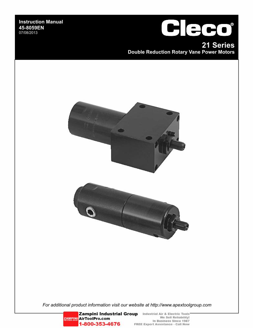
21 SeriesDouble Reduction Rotary Vane Power Motors
Page 2
45-8059EN07/08/2013
Cleco®
General Information
For this Instruction ManualThis Instruction Manual is the Original Instruction Manual intended for all persons who will operate and maintain these tools.
This Instruction Manualprovides important notes for the safe and efficient use of these tools.• describes the function and operation of the 21 series tools.• serves as a reference guide for technical data, service intervals and spare parts ordering.• provides information on optional equipment.•
Identification text:21 represents all models of the rotary vane power motor as described in this manual
Ú indicates a required action• indicates a list<..> indicates a reference number from the exploded parts drawingsArial indicates an important feature or instruction written in Arial Bold
Identification graphic:¢ indicates a directional movement
ò indicates a function or force
Copyright protection:Apex Tool Group, LLC reserves the right to modify, supplement or improve this document or the product without prior notice. This document may not be reproduced in any way, shape or form, in full or parts thereof, or copied to another natural or machine readable language or to a data carrier, whether electronic, mechanical, optical or otherwise without the express permission of Apex Tool Group, LLC.
Page 3
45-8059EN07/08/2013
Cleco®
Nomenclature
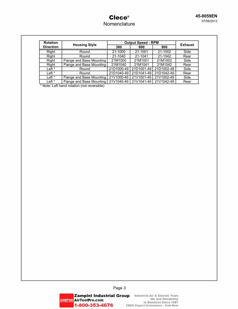
380 600 900Right Round 21-1000 21-1001 21-1002 SideRight Round 21-1040 21-1041 21-1042 RearRight Flange and Base Mounting 21M1000 21M1001 21M1002 SideRight Flange and Base Mounting 21M1040 21M1041 21M1042 RearLeft * Round 21D1000-49 21D1001-49 21D1002-49 SideLeft * Round 21D1040-49 21D1041-49 21D1042-49 RearLeft * Flange and Base Mounting 21V1000-49 21V1001-49 21V1002-49 SideLeft * Flange and Base Mounting 21V1040-49 21V1041-49 21V1042-49 Rear
* Note: Left hand rotation (not reversible)
Rotation Direction Housing Style Output Speed - RPM Exhaust
Page 4
45-8059EN07/08/2013
Cleco®
Contents
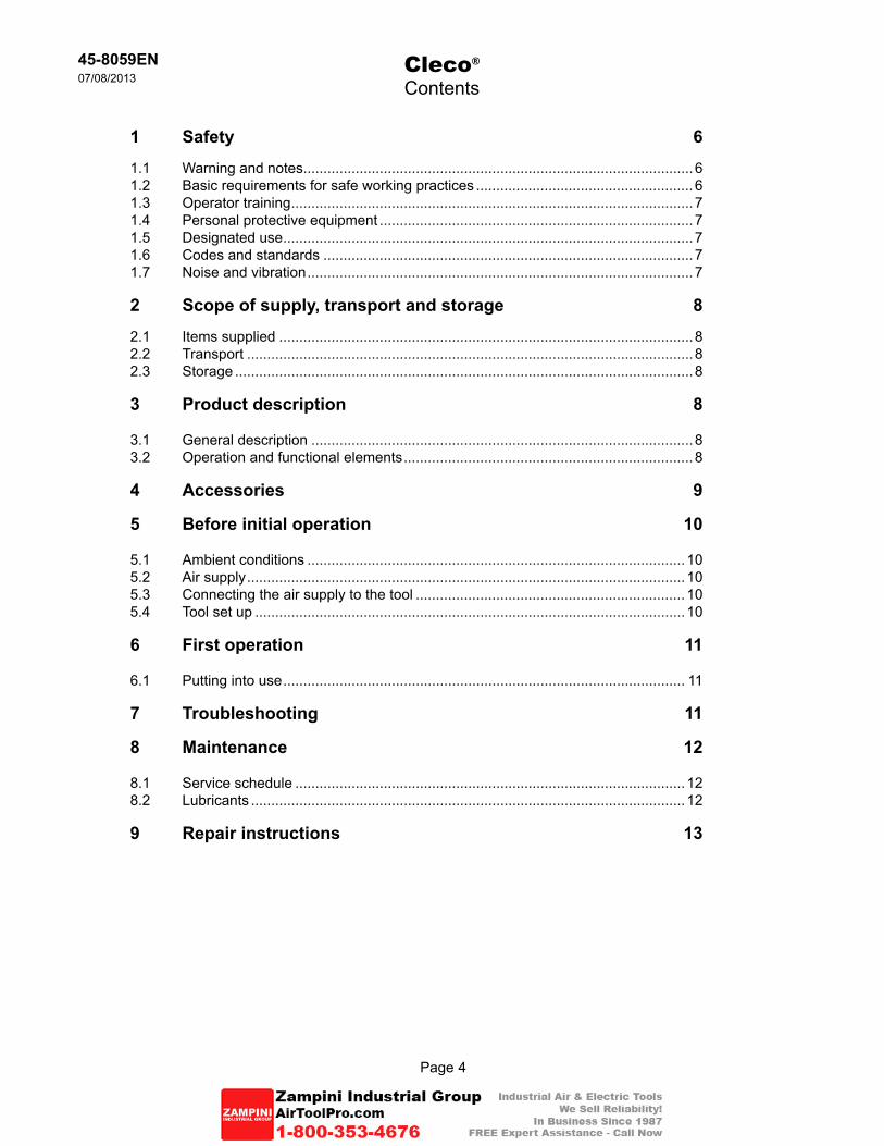
1 Safety 6
1.1 Warning and notes .................................................................................................61.2 Basic requirements for safe working practices ...................................................... 61.3 Operator training ....................................................................................................71.4 Personal protective equipment ..............................................................................71.5 Designated use ......................................................................................................71.6 Codes and standards ............................................................................................71.7 Noise and vibration ................................................................................................7
2 Scope of supply, transport and storage 8
2.1 Items supplied .......................................................................................................82.2 Transport ...............................................................................................................82.3 Storage ..................................................................................................................8
3 Product description 8
3.1 General description ...............................................................................................83.2 Operation and functional elements ........................................................................8
4 Accessories 9
5 Before initial operation 10
5.1 Ambient conditions ..............................................................................................105.2 Air supply .............................................................................................................105.3 Connecting the air supply to the tool ...................................................................105.4 Tool set up ...........................................................................................................10
6 First operation 11
6.1 Putting into use .................................................................................................... 11
7 Troubleshooting 11
8 Maintenance 12
8.1 Service schedule .................................................................................................128.2 Lubricants ............................................................................................................12
9 Repair instructions 13
Page 5
45-8059EN07/08/2013
Cleco®
Contents
10 Spare parts 14
10.1 21 Series - Side Exhaust .....................................................................................1410.2 21 Series - Rear Exhaust ....................................................................................16
11 Technical data 18
11.1 21 Series Specifications ......................................................................................18
12 Service 19
12.1 Replacement parts ..............................................................................................1912.2 Tool repairs ..........................................................................................................1912.3 Warranty repairs ..................................................................................................19
13 Disposal 19
Page 6
45-8059EN07/08/2013
Cleco®
21 Series Rotary Vane Motors
1 Safety1.1 Warnings and notes
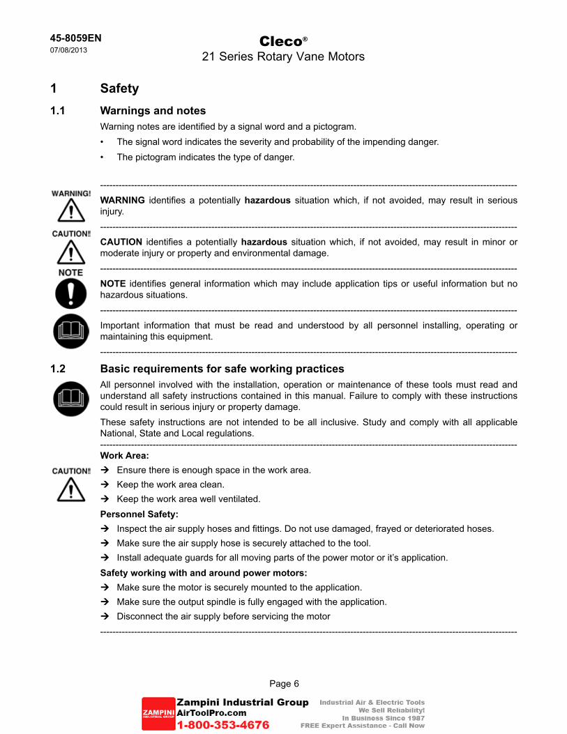
Warning notes are identified by a signal word and a pictogram.The signal word indicates the severity and probability of the impending danger.• The pictogram indicates the type of danger.•
---------------------------------------------------------------------------------------------------------------------------------------WARNING identifies a potentially hazardous situation which, if not avoided, may result in serious injury.---------------------------------------------------------------------------------------------------------------------------------------CAUTION identifies a potentially hazardous situation which, if not avoided, may result in minor or moderate injury or property and environmental damage.---------------------------------------------------------------------------------------------------------------------------------------NOTE identifies general information which may include application tips or useful information but no hazardous situations.---------------------------------------------------------------------------------------------------------------------------------------Important information that must be read and understood by all personnel installing, operating or maintaining this equipment.---------------------------------------------------------------------------------------------------------------------------------------
1.2 Basic requirements for safe working practicesAll personnel involved with the installation, operation or maintenance of these tools must read and understand all safety instructions contained in this manual. Failure to comply with these instructions could result in serious injury or property damage.These safety instructions are not intended to be all inclusive. Study and comply with all applicable National, State and Local regulations.---------------------------------------------------------------------------------------------------------------------------------------Work Area:ÚEnsure there is enough space in the work area.ÚKeep the work area clean.ÚKeep the work area well ventilated.Personnel Safety:ÚInspect the air supply hoses and fittings. Do not use damaged, frayed or deteriorated hoses.ÚMake sure the air supply hose is securely attached to the tool.ÚInstall adequate guards for all moving parts of the power motor or it’s application.Safety working with and around power motors:ÚMake sure the motor is securely mounted to the application.ÚMake sure the output spindle is fully engaged with the application.ÚDisconnect the air supply before servicing the motor---------------------------------------------------------------------------------------------------------------------------------------
Page 7
45-8059EN07/08/2013
Cleco®
21 Series Rotary Vane Motors
1.3 Operator trainingAll personnel must be properly trained before operating the 21 series tools. The 21 series tools are to be repaired by fully trained personnel only.
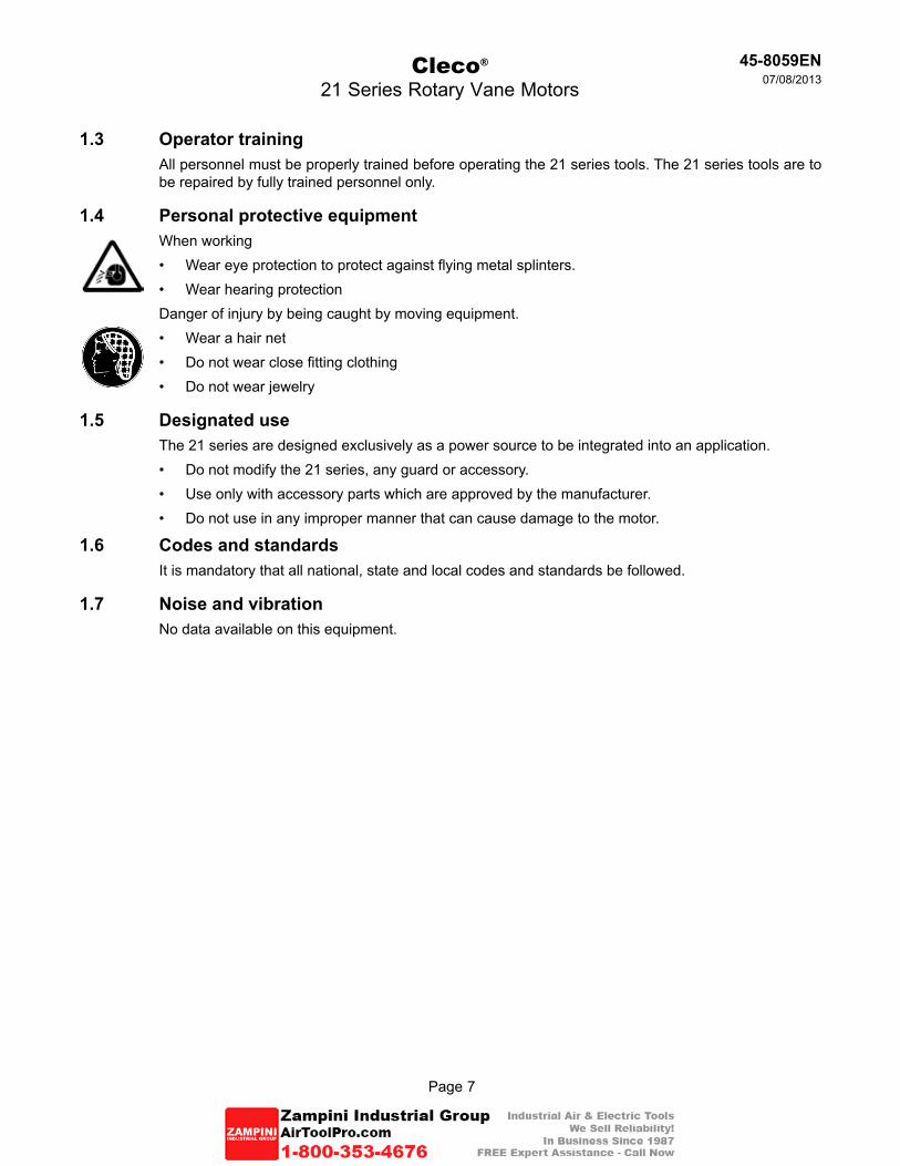
1.4 Personal protective equipmentWhen working
Wear eye protection to protect against flying metal splinters.• Wear hearing protection•
Danger of injury by being caught by moving equipment.Wear a hair net• Do not wear close fitting clothing• Do not wear jewelry•
1.5 Designated useThe 21 series are designed exclusively as a power source to be integrated into an application.
Do not modify the 21 series, any guard or accessory.• Use only with accessory parts which are approved by the manufacturer.• Do not use in any improper manner that can cause damage to the motor.•
1.6 Codes and standardsIt is mandatory that all national, state and local codes and standards be followed.
1.7 Noise and vibrationNo data available on this equipment.
Page 8
45-8059EN07/08/2013
Cleco®
21 Series Rotary Vane Motors
2 Scope of supply, transport and storage2.1 Items supplied
Check shipment for transit damage and ensure that all items have been supplied:1 21 series motor1 45-8059EN instruction manual1 Declaration of Conformity (if applicable)1 Lubrication sheet1 Warranty statement
2.2 Transport
Transport and store the 21 series in the original packaging. The packaging is recyclable.
2.3 StorageFor short term storage (less than 2 hours) and protection against damage:ÚSecure the 21 series to avoid accidental startup.
For storage longer than 2 hours:ÚDisconnect the air supply from the 21 series
3 Product description3.1 General description
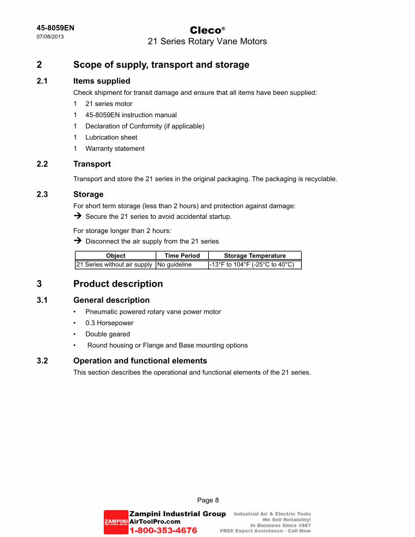
Pneumatic powered rotary vane power motor• 0.3 Horsepower• Double geared• Round housing or Flange and Base mounting options•
3.2 Operation and functional elementsThis section describes the operational and functional elements of the 21 series.
Object Time Period Storage Temperature21 Series without air supply No guideline -13°F to 104°F (-25°C to 40°C)
Page 9
45-8059EN07/08/2013
Cleco®
21 Series Rotary Vane Motors
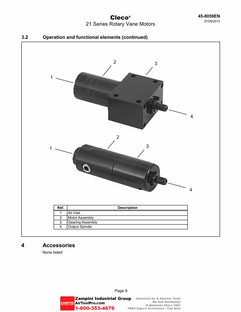
3.2 Operation and functional elements (continued)
1
3
Ref. Description1 Air Inlet2 Motor Assembly3 Gearing Assembly4 Output Spindle
2
4
4 AccessoriesNone listed
1 3
4
2
Page 10
45-8059EN07/08/2013
Cleco®
21 Series Rotary Vane Motors
5 Before initial operation5.1 Ambient conditions
Ambient temperature: 41°F (5°C) to a maximum of 104°F (40°C)
Acceptable relative humidity: 25% to 90%, non-condensing
5.2 Air supply
To attain consistent results, maintain a constant working pressure using a suitable air line unit consisting of a filter, lubricator and regulator.ÚThe inside diameter of the air hose must be free of residue, clean if necessary.ÚIf a line lubricator is used, it should be filled daily
5.3 Connecting the air supply to the tool---------------------------------------------------------------------------------------------------------------------------------------The air hose can disconnect from the motor by itself and whip around uncontrollably.ÚTurn off the compressed air before connecting to the motor.ÚSecurely connect the air hose to the motor.ÚTurn on the compressed air.---------------------------------------------------------------------------------------------------------------------------------------
5.4 Tool set up
The motor must be configured for the application.
Parameter Description
Air HoseAir inlet: 1/4" (6,4 mm)5/16" I.D. Air Hose: Maximum length run of 10.0' (3 m)3/8" I.D. Air Hose: Runs over 10.0' (3 m)
Working pressure range 60 to 100 psi (414 to 689 kPa)Recommended: 90 psi (620 kPa)
Compressed air Air quality according to ISO 8573-1, quality class 2.4.3The compressed air must be clean and dry.
Page 11
45-8059EN07/08/2013
Cleco®
21 Series Rotary Vane Motors
6 First operation6.1 Putting into use
The 21 series are rotary vane type motors. All motors feature durable construction with precision heavy-duty bearings throughout, and multiple blade rotors for smooth power. These motors require air line lubrication for long, trouble-free service. The 21 series motors perform satisfactorily in high temperature areas up to 200°F (93°C).
ÚMake sure the air line is clean and free of scale and dirt before connecting to the motor.
ÚMake sure all pipe fittings are securely tightened to prevent air leaks.
ÚMake sure the air supply is securely attached and the compressor is turned on.
ÚMake sure the output spindle is properly engaged with the application.
ÚMake sure all necessary guards are in place to protect operator from rotating mechanisms.
If an excessive amount of water is found in the air line, a water trap should be installed to trap as much as possible before it reaches the 21 series motor.
7 TroubleshootingMalfunction Possible causes Remedy
Improper air supply ÚMake sure there is adequate air pressure at the tool air inlet
Motor dry from lack of lubrication Ú Check airline lubricator for proper function
Broken gears ÚTool disassembly required (parts replacement)
Improper air supply ÚMake sure there is adequate air pressure at the tool air inlet
Motor dry from lack of lubrication Ú Check airline lubricator for proper function
Tool does not start
Tool runs slow and lacks torque
Page 12
45-8059EN07/08/2013
Cleco®
21 Series Rotary Vane Motors
8 Maintenance---------------------------------------------------------------------------------------------------------------------------------------Danger of injury from accidental start up.Turn off the compressed air before performing any maintenance.
---------------------------------------------------------------------------------------------------------------------------------------
8.1 Service scheduleOnly qualified and trained personnel are permitted to perform maintenance on these motors.Regular maintenance reduces operating faults, repair costs and downtime. In addition to the following service schedule, implement a safety related maintenance program that takes the local regulations for repair and maintenance for all operating phases of the motor into account.
8.2 LubricantsFor proper function and long service life, use of the correct lubricant is essential.
Oil identificationUse a light air tool oil, Cleco part number 500021. This oil is available from Apex Tool Group in the following quantities:
533484: 1 pint533485: 1 gallon
DO NOT SUBSITUTE LUBRICANTS!
Maintenance Interval
Daily
ÚÚÚÚ
Visual inspection of air supply hose and connectionsInspect airline filter, regulator and lubricator for proper operationCheck the tool for excessive vibration or unusual noisesVisual inspection of all external components of the tool
WeeklyÚÚÚ
Inspect the air hose for damage or wearinspect the output spindle for damage or wearInspect the airline lubrication for proper function
Designation
Page 13
45-8059EN07/08/2013
Cleco®
21 Series Rotary Vane Motors
9 Repair instructions
Page 14
45-8059EN07/08/2013
Page 14
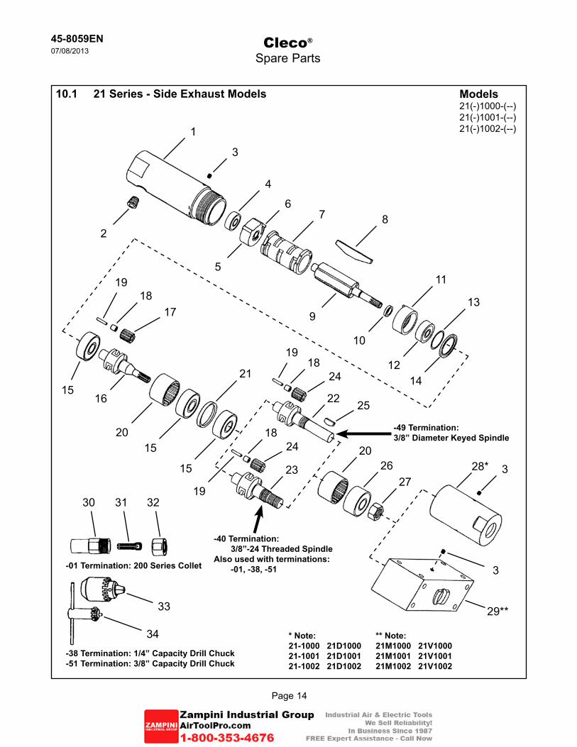
10.1 21 Series - Side Exhaust Models
Cleco®
Spare Parts
1
Models21(-)1000-(--)21(-)1001-(--)21(-)1002-(--)
2
3
4
7 8
115
21
20
22
1817
20
15
15
3-01 Termination: 200 Series Collet
6
9
10
19
12
13
14
19
1615
1819
24
1824
25
272623 328*
29**
30 31 32
-38 Termination: 1/4” Capacity Drill Chuck-51 Termination: 3/8” Capacity Drill Chuck
34
33
-40 Termination:3/8”-24 Threaded Spindle
Also used with terminations:-01, -38, -51
-49 Termination:3/8” Diameter Keyed Spindle
** Note:21M1000 21V100021M1001 21V100121M1002 21V1002
* Note:21-1000 21D100021-1001 21D100121-1002 21D1002
45-8059EN07/08/2013
Page 15
ENDescription
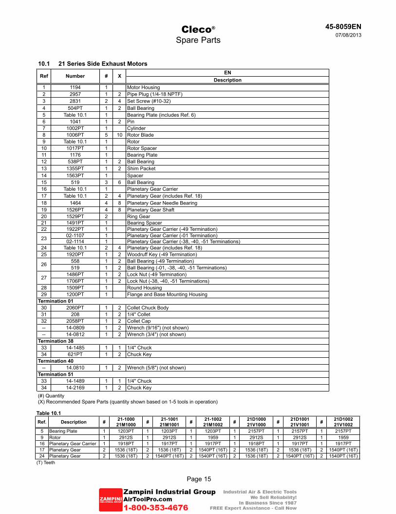
1 1194 1 Motor Housing2 2957 1 2 Pipe Plug (1/4-18 NPTF)3 2831 2 4 Set Screw (#10-32)4 504PT 1 2 Ball Bearing5 Table 10.1 1 Bearing Plate (includes Ref. 6)6 1041 1 2 Pin7 1002PT 1 Cylinder8 1006PT 5 10 Rotor Blade9 Table 10.1 1 Rotor
10 1017PT 1 Rotor Spacer11 1176 1 Bearing Plate12 538PT 1 2 Ball Bearing13 1355PT 1 2 Shim Packet14 1563PT 1 Spacer15 519 3 6 Ball Bearing16 Table 10.1 1 Planetary Gear Carrier17 Table 10.1 2 4 Planetary Gear (includes Ref. 18)18 1464 4 8 Planetary Gear Needle Bearing19 1526PT 4 8 Planetary Gear Shaft20 1529PT 2 Ring Gear21 1491PT 1 Bearing Spacer22 1922PT 1 Planetary Gear Carrier (-49 Termination)
02-1107 1 Planetary Gear Carrier (-01 Termination)02-1114 1 Planetary Gear Carrier (-38, -40, -51 Terminations)
24 Table 10.1 2 4 Planetary Gear (includes Ref. 18)25 1920PT 1 2 Woodruff Key (-49 Termination)
558 1 2 Ball Bearing (-49 Termination)519 1 2 Ball Bearing (-01, -38, -40, -51 Terminations)
1486PT 1 2 Lock Nut (-49 Termination)1706PT 1 2 Lock Nut (-38, -40, -51 Terminations)
28 1509PT 1 Round Housing29 1200PT 1 Flange and Base Mounting Housing
30 2060PT 1 2 Collet Chuck Body31 208 1 2 1/4" Collet32 2058PT 1 2 Collet Cap-- 14-0809 1 2 Wrench (9/16") (not shown)-- 14-0812 1 2 Wrench (3/4") (not shown)
33 14-1485 1 1 1/4" Chuck34 621PT 1 2 Chuck Key
-- 14.0810 1 2 Wrench (5/8") (not shown)
33 14-1489 1 1 1/4" Chuck34 14-2169 1 2 Chuck Key
(#) Quantity(X) Recommended Spare Parts (quantity shown based on 1-5 tools in operation)
Termination 51
Termination 40
23
26
27
Termination 01
Termination 38
10.1 21 Series Side Exhaust Motors
Ref Number # X
Cleco®
Spare Parts
Table 10.1Ref. Description # 21-1000
21M1000 # 21-100121M1001 # 21-1002
21M1002 # 21D100021V1000 # 21D1001
21V1001 # 21D100221V1002
5 Bearing Plate 1 1203PT 1 1203PT 1 1203PT 1 2157PT 1 2157PT 1 2157PT9 Rotor 1 2912S 1 2912S 1 1959 1 2912S 1 2912S 1 1959
16 Planetary Gear Carrier 1 1918PT 1 1917PT 1 1917PT 1 1918PT 1 1917PT 1 1917PT17 Planetary Gear 2 1536 (18T) 2 1536 (18T) 2 1540PT (16T) 2 1536 (18T) 2 1536 (18T) 2 1540PT (16T)24 Planetary Gear 2 1536 (18T) 2 1540PT (16T) 2 1540PT (16T) 2 1536 (18T) 2 1540PT (16T) 2 1540PT (16T)
(T) Teeth
Page 16
45-8059EN07/08/2013
Cleco®
Spare Parts
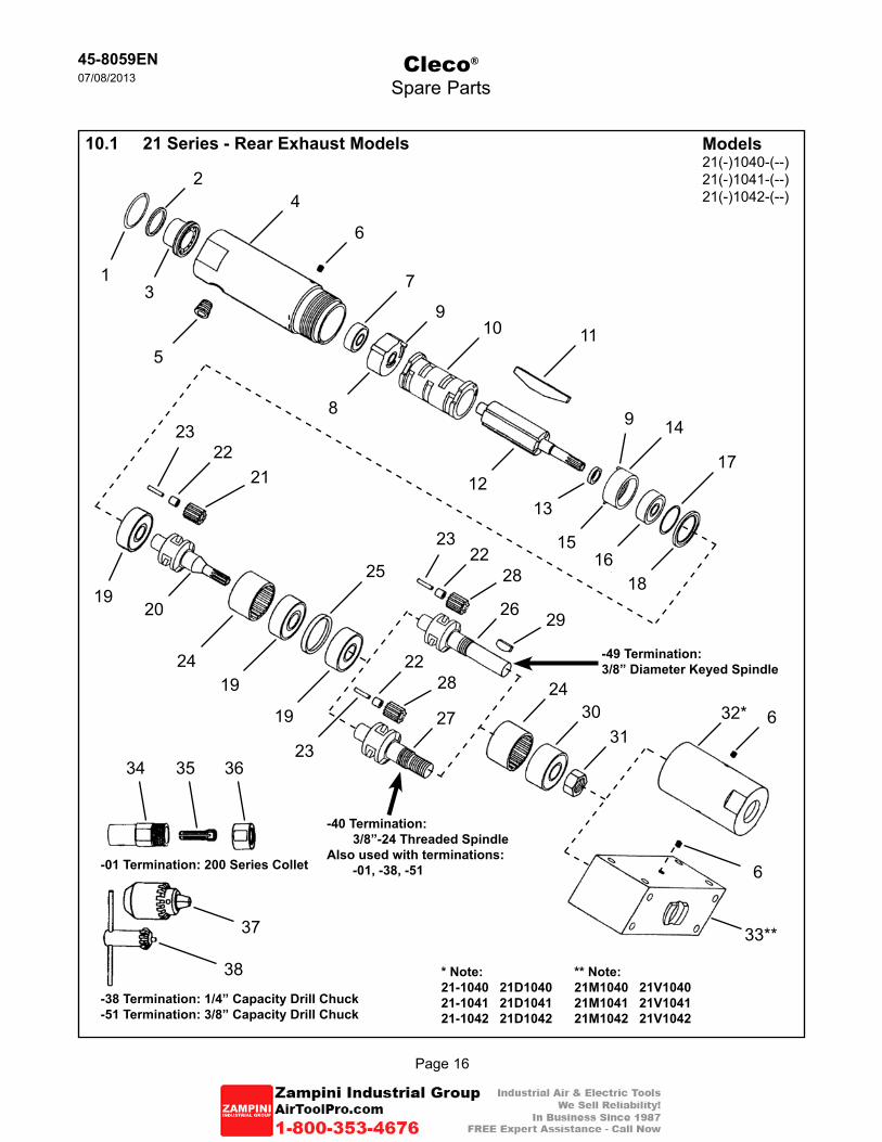
10.1 21 Series - Rear Exhaust Models
4
Models21(-)1040-(--)21(-)1041-(--)21(-)1042-(--)
5
6
7
10 11
148
25
24
26
2221
24
19
19
6-01 Termination: 200 Series Collet
9
1213
23
16
17
18
23
2019
2223
28
2228
29
313027 632*
33**
34 35 36
-38 Termination: 1/4” Capacity Drill Chuck-51 Termination: 3/8” Capacity Drill Chuck
38
37
-40 Termination:3/8”-24 Threaded Spindle
Also used with terminations:-01, -38, -51
-49 Termination:3/8” Diameter Keyed Spindle
** Note:21M1040 21V104021M1041 21V104121M1042 21V1042
* Note:21-1040 21D104021-1041 21D104121-1042 21D1042
2
13
9
15
Page 17
45-8059EN07/08/2013
Cleco®
Spare Parts
ENDescription
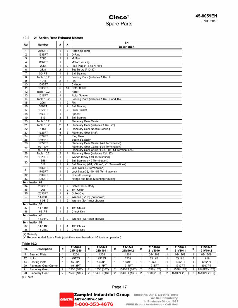
1 2690PT 1 3 Retaining Ring2 1838PT 1 3 O-Ring3 2685 1 2 Muffler4 1192PT 1 Motor Housing5 2957 1 2 Pipe Plug (1/4-18 NPTF)6 2831 2 4 Set Screw (#10-32)7 504PT 1 2 Ball Bearing8 Table 10.2 1 Bearing Plate (includes 1 Ref. 9)9 1041 2 4 Pin
10 1002PT 1 Cylinder11 1006PT 5 10 Rotor Blade12 Table 10.2 1 Rotor13 1017PT 1 Rotor Spacer14 Table 10.2 1 Bearing Plate (includes 1 Ref. 9 and 15)15 2964 1 2 Pin16 538PT 1 2 Ball Bearing17 1355PT 1 2 Shim Packet18 1563PT 1 Spacer19 519 3 6 Ball Bearing20 Table 10.2 1 Planetary Gear Carrier21 Table 10.2 2 4 Planetary Gear (includes 1 Ref. 22)22 1464 4 8 Planetary Gear Needle Bearing23 1526PT 4 8 Planetary Gear Shaft24 1529PT 2 Ring Gear25 1491PT 1 Bearing Spacer26 1922PT 1 Planetary Gear Carrier (-49 Termination)
02-1107 1 Planetary Gear Carrier (-01 Termination)02-1114 1 Planetary Gear Carrier (-38, -40, -51 Terminations)
28 Table 10.2 2 4 Planetary Gear (includes Ref. 22)29 1920PT 1 2 Woodruff Key (-49 Termination)
558 1 2 Ball Bearing (-49 Termination)519 1 2 Ball Bearing (-01, -38, -40, -51 Terminations)
1486PT 1 2 Lock Nut (-49 Termination)1706PT 1 2 Lock Nut (-38, -40, -51 Terminations)
32 1509PT 1 Round Housing33 1200PT 1 Flange and Base Mounting Housing
34 2060PT 1 2 Collet Chuck Body35 208 1 2 1/4" Collet36 2058PT 1 2 Collet Cap-- 14-0809 1 2 Wrench (9/16") (not shown)-- 14-0812 1 2 Wrench (3/4") (not shown)
37 14-1485 1 1 1/4" Chuck38 621PT 1 2 Chuck Key
-- 14.0810 1 2 Wrench (5/8") (not shown)
37 14-1489 1 1 1/4" Chuck38 14-2169 1 2 Chuck Key
(#) Quantity(X) Recommended Spare Parts (quantity shown based on 1-5 tools in operation)
30
31
Termination 01
Termination 38
Termination 40
Termination 51
10.2 21 Series Rear Exhaust Motors
Ref Number # X
27
Table 10.2Ref. Description # 21-1040
21M1040 # 21-104121M1041 # 21-1042
21M1042 # 21D104021V1040 # 21D1041
21V1041 # 21D104221V1042
8 Bearing Plate 1 1204 1 1204 1 1204 1 02-1209 1 02-1209 1 02-120912 Rotor 1 2912S 1 2912S 1 1959 1 2912S 1 2912S 1 195914 Bearing Plate 1 1531PT 1 1531PT 1 1531PT 1 1262PT 1 1262PT 1 1262PT20 Planetary Gear Carrier 1 1918PT 1 1917PT 1 1917PT 1 1918PT 1 1917PT 1 1917PT21 Planetary Gear 2 1536 (18T) 2 1536 (18T) 2 1540PT (16T) 2 1536 (18T) 2 1536 (18T) 2 1540PT (16T)28 Planetary Gear 2 1536 (18T) 2 1540PT (16T) 2 1540PT (16T) 2 1536 (18T) 2 1540PT (16T) 2 1540PT (16T)
(T) Teeth
Page 18
45-8059EN07/08/2013
Cleco®
21 Series Rotary Vane Motors
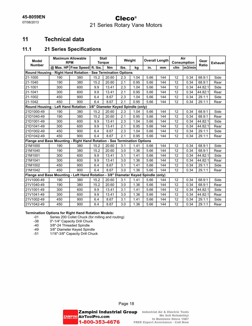
11 Technical data11.1 21 Series Specifications
@ Max. HP Free Speed ft. lbs. Nm lbs. kg in. mm cfm m3/min
21-1000 190 380 15.2 20.60 2.3 1.04 5.66 144 12 0.34 68.9:1 Side21-1040 190 380 15.2 20.60 2.1 0.95 5.66 144 12 0.34 68.9:1 Rear21-1001 300 600 9.9 13.41 2.3 1.04 5.66 144 12 0.34 44.82:1 Side21-1041 300 600 9.9 13.41 2.1 0.95 5.66 144 12 0.34 44.82:1 Rear21-1002 450 900 6.4 8.67 2.3 1.04 5.66 144 12 0.34 29.1:1 Side21-1042 450 900 6.4 8.67 2.1 0.95 5.66 144 12 0.34 29.1:1 Rear
21D1000-49 190 380 15.2 20.60 2.3 1.04 5.66 144 12 0.34 68.9:1 Side21D1040-49 190 380 15.2 20.60 2.1 0.95 5.66 144 12 0.34 68.9:1 Rear21D1001-49 300 600 9.9 13.41 2.3 1.04 5.66 144 12 0.34 44.82:1 Side21D1041-49 300 600 9.9 13.41 2.1 0.95 5.66 144 12 0.34 44.82:1 Rear21D1002-49 450 900 6.4 8.67 2.3 1.04 5.66 144 12 0.34 29.1:1 Side21D1042-49 450 900 6.4 8.67 2.1 0.95 5.66 144 12 0.34 29.1:1 Rear
21M1000 190 380 15.2 20.60 3.1 1.41 5.66 144 12 0.34 68.9:1 Side21M1040 190 380 15.2 20.60 3.0 1.36 5.66 144 12 0.34 68.9:1 Rear21M1001 300 600 9.9 13.41 3.1 1.41 5.66 144 12 0.34 44.82:1 Side21M1041 300 600 9.9 13.41 3.0 1.36 5.66 144 12 0.34 44.82:1 Rear21M1002 450 900 6.4 8.67 3.1 1.41 5.66 144 12 0.34 29.1:1 Side21M1042 450 900 6.4 8.67 3.0 1.36 5.66 144 12 0.34 29.1:1 Rear
21V1000-49 190 380 15.2 20.60 3.1 1.41 5.66 144 12 0.34 68.9:1 Side21V1040-49 190 380 15.2 20.60 3.0 1.36 5.66 144 12 0.34 68.9:1 Rear21V1001-49 300 600 9.9 13.41 3.1 1.41 5.66 144 12 0.34 44.82:1 Side21V1041-49 300 600 9.9 13.41 3.0 1.36 5.66 144 12 0.34 44.82:1 Rear21V1002-49 450 900 6.4 8.67 3.1 1.41 5.66 144 12 0.34 29.1:1 Side21V1042-49 450 900 6.4 8.67 3.0 1.36 5.66 144 12 0.34 29.1:1 Rear
-01 Series 200 Collet Chuck (for milling and routing)-38 0"-1/4" Capacity Drill Chuck-40 3/8"-24 Threaded Spindle-49 3/8" Diameter Keyed Spindle-51 1/16"-3/8" Capacity Drill Chuck
Flange and Base Mounting - Right Hand Rotation - See Termination Options
Flange and Base Mounting - Left Hand Rotation - 3/8" Diameter Keyed Spindle (only)
Termination Options for Right Hand Rotation Models:
Round Housing - Right Hand Rotation - See Termination Options
Air ConsumptionModel
Number
StallTorque WeightMaximum Allowable
RPM Gear Ratio Exhaust
Overall Length
Round Housing - Left Hand Rotation - 3/8" Diameter Keyed Spindle (only)
Page 19
45-8059EN07/08/2013
Cleco®
21 Series Rotary Vane Motors
12 Service12.1 Replacement parts
Use only original Cleco replacement parts. Failure to comply can result in reduced power and increased service requirements. The tool warranty may be voided if replacement parts are not manufactured or approved by Apex Tool Group.
12.2 Tool repairs
Only qualified and trained personnel are to repair this equipment.
12.3 Warranty repairsAll warranty repairs are to be performed by an authorized Apex Tool Group service center. Contact your local representative for assistance with warranty repair claims.
13 Disposal---------------------------------------------------------------------------------------------------------------------------------------Injuries and environmental damage from improper disposal.Components and auxiliary materials of the tool pose risks to health and the environment.ÚCapture auxiliary materials (oils, greases) when drained and dispose of them properly.ÚSeparate the packaging components and dispose of them properly.ÚComply with all applicable local regulations.
Observe local disposal guidelines for all components of this tool and its packaging.
---------------------------------------------------------------------------------------------------------------------------------------

45-8059EN/Printed in USA 07/2013/Copyright © Apex Tool Group, LLC
Apex Tool Group, LLC1000 Lufkin RoadApex, NC 27539Phone: 919-387-0099Fax: 919-387-2614www.apextoolgroup.com
Sales & Service CentersNote: All locations may not service all products. Please contact the nearest Sales & Service Center for the appropriate facility to handle your service requirements.
Detroit, MichiganApex Tool GroupSales & Service Center2630 Superior CourtAuburn Hills, MI 48326Tel: (248) 393-5640Fax: (248) 391-6295
Houston, TexasApex Tool GroupSales & Service Center6550 West Sam HoustonParkway North, Suite 200Houston, TX 77041Tel: (713) 849-2364Fax: (713) 849-2047
Lexington, South CarolinaApex Tool Group670 Industrial DriveLexington, SC 29072Tel: (800) 845-5629Tel: (803) 951-7544Fax: (803) 358-7681
Los Angeles, CaliforniaApex Tool GroupSales & Service Center6881 Stanton AvenueUnit BBuena Park, CA 90621Tel: (714) 994-1491Fax: (714) 994-9576
Seattle, WashingtonApex Tool GroupSales & Service Center2865 152nd Avenue N.ERedmond, WA 98052Tel: (425) 497-0476Fax: (425) 497-0496
York, PennsylvaniaApex Tool GroupSales & Service Center3990 East Market StreetYork, PA 17402Tel: (717) 755-2933Fax: (717) 757-5063
BrazilApex Tool GroupSales & Service CenterAv. Liberdade, 4055Zona Industrial - Iporanga18087-170 SorocabaSP BrazilTel: +55 15 2383929Fax: +55 15 2383260
CanadaApex Tool GroupSales & Service Center7631 Bath RoadMississauga, Ont. L4T 3T1CanadaTel: (866) 691-6212Tel: (905) 673-4400
ChinaCooper (China) Co., Ltd.an Apex Tool Group, LLCcompany955 Sheng Li Road,Heqing Pudong, ShanghaiChina 201201Tel: +86-21-28994176Fax: +86-21-51118446
EnglandApex Tool GroupGmbH & Co. OHGC/O Spline GaugesPiccadilly, TamworthStaffordshire B78 2ERUnited KingdomTel: +44 1827 8741 28Fax: +44 1827 8741 28
FranceApex Tool Group S.N.C.25 rue Maurice ChevalierB.P. 2877831 Ozoir-La-FerrièreCedex, FranceTel: +33 1 64 43 22 00Fax: +33 1 64 43 17 17
GermanyApex Tool GroupGmbH & Co. OHGIndustriestraße 173463 WesthausenGermanyTel: +49 (0) 73 63 81 0Fax: +49 (0) 73 63 81 222
HungaryApex Tool GroupHungaria KftPlatànfa u.29027 GyörHungaryTel: +36 96 66 1383Fax: +36 96 66 1135
IndiaApex Power Tools IndiaPrivate LimitedGala No. 1, Plot No. 5S. No. 234, 235 & 245Indialand GlobalIndustrial ParkTaluka-Mulsi, Phase IHinjawadi, Pune 411057Maharashtra, India
MexicoApex Tool Group MéxicoS. de R.L. de C.V.Vialidad El Pueblito #103Parque Industrial QuerétaroQuerétaro, QRO 76220MexicoTel: +52 (442) 211-3800Fax: +52 (442) 103-0443


