21
| Date post: | 14-Dec-2015 |
| Category: |
Documents |
| Upload: | pec21102002 |
| View: | 15 times |
| Download: | 6 times |

J3 Program 10080-1-SS-ME-009
Design and Fabrication of Double pipe and Multi Tube Exchangers
Date: 15/02/2013, Rev. 1
RECORD OF REVISIONS
Date Revision Details Revision Number
31.07.2012 Issued for Implementation 0
15.02.2013 Changes made to Clause 7.1, 8.7.5, 10.1.6 & 10.15 & Issued for Implementation
1
J3 Program 10080-1-SS-ME-009
Design and Fabrication of Double pipe and Multi Tube Exchangers
Date: 15/02/2013, Rev. 1
Contents
1. Purpose............................................................................................................................. 1
2. Scope ................................................................................................................................ 1
3. Cost competitive engineering and design ........................................................................ 1
4. Conflicts and Deviations ................................................................................................... 1
5. Definitions: ....................................................................................................................... 2
6. Abbreviations: .................................................................................................................. 2
7. Codes and Standards: ....................................................................................................... 3
8. Basic Design/Assembly/Methodology: ............................................................................ 4
9. Accessories: .................................................................................................................... 12
10. Inspection and Testing: .................................................................................................. 12
11. Preparation for shipment: .............................................................................................. 16
12. Vendor Data Requirement: ............................................................................................ 16
13. Attachments: .................................................................................................................. 18

J3 Program 10080-1-SS-ME-009
Design and Fabrication of Double pipe and Multi Tube Exchangers
Date: 15/02/2013, Rev. 1
10080-1-SS-ME-009 Page 1 of 18
1. Purpose
1.1. The purpose of this specification is to define the minimum design and fabrication requirements for double pipe and multi tube heat exchangers.
2. Scope
2.1. It is the intention of this specification that the SELLER provides the most economical exchanger based on his standard equipment design and fabrication methods provided the SELLER complies with the requirements of the specified design code, TEMA standards, and this specification.
3. Cost competitive engineering and design
To achieve value engineering and cost effective design with required quality and integrity following parameters / criteria shall be considered.
3.1. Standardization of size (MOC, Thickness, Length, Diameter)
3.2. Optimum Design (Size)
3.3. Proper selection of materials (CS, SS, Non-Ferrous)
3.4. Judicious Inspection (Final Inspection, Stage wise Inspection, Extent of Inspection, Certification level, TPI)
4. Conflicts and Deviations
In case of contradiction between codes, specifications and standards or other documents relating to an enquiry or order, the following order of precedence shall apply:
a) Design and construction code, including national and/or local regulations
b) Purchase order and subsequent change order
c) Data sheets and drawings
d) This specification
e) Other project specifications and standards
f) Client specifications and standards
g) Other national and international standards
h) Accepted SELLER’s specifications and standards
Note that if the requirements of b) through h) are more stringent than a) then these shall govern.
Should conflicts occur it shall be the responsibility of the SELLER to call the BUYER's attention to the conflict and request a ruling or interpretation from

J3 Program 10080-1-SS-ME-009
Design and Fabrication of Double pipe and Multi Tube Exchangers
Date: 15/02/2013, Rev. 1
10080-1-SS-ME-009 Page 2 of 18
BUYER. While the governing order of precedence is given, the SELLER shall not assume any instruction without reference to the BUYER.
5. Definitions:
The definitions of key terms used in this specification are as follows:
BUYER:- Reliance Industries Ltd (RIL)
SELLER:- The firm contracted to supply the equipment to BUYER.
Double pipe- Consist of larger pipe inside which an inner pipe is running.
Hair pin:- Single tube or pipe bends to form a shape of hair pin.
Multi Tube:- Bunch of tubes together bent to form a single hair pin.
Fixed tube double pipe exchanger:- Inner tube or pipe passing through the outer pipe and ends of outer pipe are welded on to the inner pipe or tube using a doughnut or pipe caps.
Separated high pressure closure:- Tube sheet of multi tube exchanger is connected to channel cover using a solid metal gasket or taper lock gasket. Barrel end of tube sheet connected to shell by means of split ring and O-ring gasket.
Separated low pressure closure:- Tube sheet hub is extended to form tongue and groove joint with channel cover flange. Gasket in the groove can be jacketed type or spiral wound type. Tube sheet barrel is connected to shell flange by means of split ring and O-ring gasket.
Combined Closure:- Between tube side and shell side flange common compression flange is used when tube sheet does not have barrel type construction.
Return End Bonnet Enclosure:- Floating end flanged bonnet cover which facilitates hair pin pulling from U-bend end. This flanged bonnet is oblong shaped joining the two shells or pipes.
Compression Flange:- A loose flange used to compress the O-ring or Octagonal type gasket.
6. Abbreviations:
ASME American Society of Mechanical Engineers
BS British Standard
NDT / NDE Non-destructive test / Examination
TEMA Tubular Exchanger Manufacturers Association,
IBR Indian Boiler Regulation
J3 Program 10080-1-SS-ME-009
Design and Fabrication of Double pipe and Multi Tube Exchangers
Date: 15/02/2013, Rev. 1
10080-1-SS-ME-009 Page 3 of 18
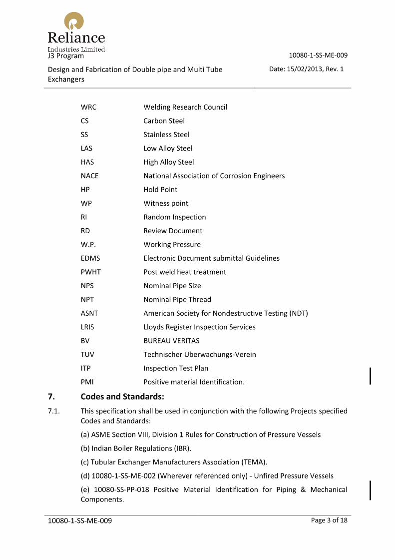
WRC Welding Research Council
CS Carbon Steel
SS Stainless Steel
LAS Low Alloy Steel
HAS High Alloy Steel
NACE National Association of Corrosion Engineers
HP Hold Point
WP Witness point
RI Random Inspection
RD Review Document
W.P. Working Pressure
EDMS Electronic Document submittal Guidelines
PWHT Post weld heat treatment
NPS Nominal Pipe Size
NPT Nominal Pipe Thread
ASNT American Society for Nondestructive Testing (NDT)
LRIS Lloyds Register Inspection Services
BV BUREAU VERITAS
TUV Technischer Uberwachungs-Verein
ITP Inspection Test Plan
PMI Positive material Identification.
7. Codes and Standards:
7.1. This specification shall be used in conjunction with the following Projects specified Codes and Standards:
(a) ASME Section VIII, Division 1 Rules for Construction of Pressure Vessels
(b) Indian Boiler Regulations (IBR).
(c) Tubular Exchanger Manufacturers Association (TEMA).
(d) 10080-1-SS-ME-002 (Wherever referenced only) - Unfired Pressure Vessels
(e) 10080-SS-PP-018 Positive Material Identification for Piping & Mechanical Components.

J3 Program 10080-1-SS-ME-009
Design and Fabrication of Double pipe and Multi Tube Exchangers
Date: 15/02/2013, Rev. 1
10080-1-SS-ME-009 Page 4 of 18
7.2. Unless otherwise specified the editions of the codes and standards which apply shall be those current on the date stated in the placement of order on the Detailed Engineering Contractor and shall be effective for the full tenure of the project, including all revisions and addenda up to and including that date.
8. Basic Design/Assembly/Methodology:
8.1. General
8.1.1. Design pressures, design temperature, operating conditions, fluid properties, pressure drops and fouling factors shall be as specified on the exchanger data sheet.
8.1.2. Cooling water shall be on the tube side only.
8.1.3. Double pipe exchangers are recommended for surface area ≤ 10 m2 and multi tube exchangers are recommended when the surface area ≤ 60 m2.
8.1.4. Suggested maximum overall length of the exchanger shall be 10 m.
8.1.5. The SELLER shall provide the full mechanical design and guarantee.
If specified in the Material Requisition, the SELLER shall verify the thermal design and state in his proposal that he will supply complete thermal, hydraulic and vibration guarantees.
8.1.6. When exchanger thermal design is provided by the BUYER, it shall be SELLER's responsibility to confirm the exchanger geometry provided. Shell diameter specified in SELLER proposal shall be their calculated value. Price adjustments after the order for increased shell diameters will not be allowed.
8.1.7. When shell side fouling factor exceeds 0.0004 m2 C/W, the shell side pressure drop shall be calculated with all leakage streams blocked. This pressure drop shall not exceed clean pressure drop by more than fifty (50) present.
8.1.8. Unless otherwise specified, maximum design temperature shall be 10% above the maximum anticipated operating temperature or maximum operating temperature + 28 deg C whichever is greater.
8.1.9. Unless otherwise specified, maximum design pressure shall be 10% above the maximum anticipated operating pressure or maximum operating pressure + 2 kg/cm2 whichever is greater.
8.1.10. All bolting for girth flanges and nozzle flanges shall be UNC/UN8 series. Nuts shall be heavy series.
8.1.11. Mechanical design of exchangers shall be as per ASME Sec- VIII Div- I with TEMA tolerances.

J3 Program 10080-1-SS-ME-009
Design and Fabrication of Double pipe and Multi Tube Exchangers
Date: 15/02/2013, Rev. 1
10080-1-SS-ME-009 Page 5 of 18
8.1.12. For exchangers under steam service, steam side of the exchangers shall be subjected to IBR design and manufacturing requirements. This shall be considered as an additional requirement. SELLER shall undertake to obtain all necessary approvals from IBR. Documentation duly certified by IBR shall be despatched along with equipment.
8.1.13. Double pipe can be combined variety of series and parallel arrangement. Series are one above the other and parallel are side by side.
8.1.14. Corrosion allowance of 3 mm shall be considered, unless otherwise specified. Tube or inner pipe may be exempted if so specified on the exchanger data sheet.
8.1.15. Differential pressure design shall not be permitted.
8.1.16. Hair pin shall not be used if tube side is highly fouling medium.
8.1.17. Finned tube shall not be used if shell side is fouling medium.
8.1.18. Type of Exchangers-
(i) Fixed tube double pipe exchanger
(ii) Removable type double pipe exchanger
(iii) Hair pin plain tube double pipe exchanger
(iv) Hair pin finned tube double pipe exchanger
(v) Multi tube type exchangers
(a) Plain tube type
(b) Finned tube type
(c) Twisted tube type
8.1.19. Corrosion allowance of 5 mm shall be considered for CS & LAS in sour service.
8.2. Tubes & Tube Bundles for multi tube exchangers
8.2.1. Bypass seal devices are required when the radial clearance between the outer tube limit (OTL) and shell is greater than one tube diameter.
8.2.2. Sealing roads and support strips shall be used to support the tubes.
8.2.3. U tube shall be free for thermal expansion.
8.2.4. Bundle shall be removable without dismantling piping connections.
8.2.5. Baffles / Support plates shall be provided with suitable notches to facilitate venting and draining of shell. Support / baffles plates shall not be welded to shell and they shall be attached to tubesheet by means of tie rods.
8.2.6. Except otherwise specified, exchanger tubes and pipe shall be SEAMLESS type only. The maximum tube length shall not exceed 10 meter

J3 Program 10080-1-SS-ME-009
Design and Fabrication of Double pipe and Multi Tube Exchangers
Date: 15/02/2013, Rev. 1
10080-1-SS-ME-009 Page 6 of 18
The preferred tube size for double pipe exchangers shall be:
Carbon Steel and Low Alloys 25.4mm O.D. 12 BWG (min) or Sch 40 pipe
Stainless 25.4mm O.D. 14 BWG (min) or Sch 20 pipe
For double pipe exchangers, which are subject to IBR regulations, the following tube standard shall be preferred (for U-bundles the inner tubes may need to be thicker to ensure bend thickness is adequate):
Carbon Steel 25.4mm O.D. 13 BWG min wall.
Stainless Steel 25.4mm O.D. 14 BWG min wall.
8.2.7. Tube size range for double pipe exchangers shall be 3/4" to 4".
For multi tube exchanger's tube size range shall be 3/4" to 4".
8.2.8. Tube holes in stainless steel tubesheets shall be furnished in conformity with special close fit dimensions and tolerances as referenced in TEMA.
8.2.9. Tube fins shall be longitudinal and minimum thickness shall be 0.8mm.
8.2.10. Tube hole drilling on the baffles and support plates shall be with TEMA close tolerance fit. Tube hole dia. shall be tube OD + 0.4 mm.
8.2.11. Impingement plate shall be provided if required as per TEMA.
8.3. Tubesheet of multi tube exchangers:-
8.3.1. Tubesheet thickness shall be calculated as per ASME VIII Division 1.
8.3.2. Design of fixed tube double pipe exchangers shall take into consideration the most stringent of the following criteria in determining the differential thermal expansion:
a) Normal operating conditions.
b) Shell side start up, no fluid tube side.
c) Tube side start up, no fluid shell side
e) Steam out or other cleaning procedures when specified.
8.3.3. Unless otherwise noted on the data sheet, the design temperature for tubesheets shall be taken as the maximum of either the shell side or tube side design temperatures as specified on the exchanger data sheets.
8.3.4. Tube to Tubesheet Joints
8.3.4.1. Expanded tube-to-tubesheet joints
Tube-to-tubesheet joints shall be expanded into two grooves in the tube sheet. The length of full expansion shall be 50mm with light expansion for the remainder to within 3mm of the shell side face of the tubesheet.

J3 Program 10080-1-SS-ME-009
Design and Fabrication of Double pipe and Multi Tube Exchangers
Date: 15/02/2013, Rev. 1
10080-1-SS-ME-009 Page 7 of 18
A minimum of two grooves each 0.4mm deep and 3mm wide shall be provided at 6mm spacing in the tube-hole of tube sheet.
Thinning limited to 4-5% for stainless steel tubes and 8-10% for carbon steel tubes.
8.3.4.2. Welded tube to tubesheet joints:
(i) Tube-tubesheet welding shall comply with requirements of ASME Sec VIII Div.1
(a) Strength welded tube-tubesheet joints shall have minimum two welds runs with different start and stop runs.
(b) Only inert gas shielded welding process shall be applied.
(c) For SS welding inter-pass temperature shall not exceed 175 C and for SS410 not to exceed 300 C.
(d) Duration of pressure test shall be minimum one hour.
(e) Ni-Mo, Ni-MO-Cr alloy welding shall not be carried out when base metal temp exceeds 100 C.
8.3.4.3. Seal welded tube-tubesheet joints without two expansion grooves shall not be acceptable.
8.4. Tube supports
Support strips and sealing roads / strips & tie rods shall be provided to adequate support the tube and prevent tube vibrations.
8.5. Shells, Shell Covers and Shell Supports
8.5.1. Standard outer pipe (shell) size can be 2" to 6" for double pipe exchangers.
For multi tube type, shell size can be 4" to 24".
8.5.2. Minimum outer pipe or shell thickness shall be as follows:-
Pipe Size CS SS
4"-6" Sch 40 3.2 mm
8"-12" Sch 30 3.2 mm
14"-16" Sch STD 4.8 mm
J3 Program 10080-1-SS-ME-009
Design and Fabrication of Double pipe and Multi Tube Exchangers
Date: 15/02/2013, Rev. 1
10080-1-SS-ME-009 Page 8 of 18
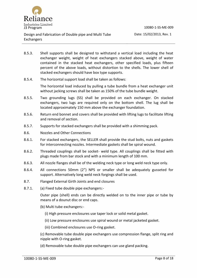
8.5.3. Shell supports shall be designed to withstand a vertical load including the heat exchanger weight, weight of heat exchangers stacked above, weight of water contained in the stacked heat exchangers, other specified loads, plus fifteen percent of the above loads, without distortion to the shells. The lower shell of stacked exchangers should have box type supports.
8.5.4. The horizontal support load shall be taken as follows:
The horizontal load induced by pulling a tube bundle from a heat exchanger unit without jacking screws shall be taken as 150% of the tube bundle weight.
8.5.5. Two grounding lugs (SS) shall be provided on each exchanger. On stacked exchangers, two lugs are required only on the bottom shell. The lug shall be located approximately 150 mm above the exchanger foundation.
8.5.6. Return end bonnet and covers shall be provided with lifting lugs to facilitate lifting and removal of section.
8.5.7. Supports for stacked exchangers shall be provided with a shimming pack.
8.6. Nozzles and Other Connections
8.6.1. For stacked exchangers, the SELLER shall provide the stud bolts, nuts and gaskets for interconnecting nozzles. Intermediate gaskets shall be spiral wound.
8.6.2. Threaded couplings shall be socket- weld type. All couplings shall be fitted with plugs made from bar stock and with a minimum length of 100 mm.
8.6.3. All nozzle flanges shall be of the welding neck type or long weld neck type only.
8.6.4. All connections 50mm (2”) NPS or smaller shall be adequately gusseted for support. Alternatively long weld neck forgings shall be used.
8.7. Flanged External Girth Joints and end closures
8.7.1. (a) Fixed tube double pipe exchangers:-
Outer pipe (shell) ends can be directly welded on to the inner pipe or tube by means of a dounut disc or end caps.
(b) Multi tube exchangers:-
(i) High pressure enclosures use taper lock or solid metal gasket.
(ii) Low pressure enclosures use spiral wound or metal jacketed gasket.
(iii) Combined enclosures use O-ring gasket.
(c) Removable tube double pipe exchangers use compression flange, split ring and nipple with O-ring gasket.
(d) Removable tube double pipe exchangers can use gland packing.

J3 Program 10080-1-SS-ME-009
Design and Fabrication of Double pipe and Multi Tube Exchangers
Date: 15/02/2013, Rev. 1
10080-1-SS-ME-009 Page 9 of 18
8.7.2. All end flanges shall be checked for axial alignment and gasket face flatness after welding to the shell and stress relieving. Final gasket surface machining must be done after welding and stress relieving.
8.7.3. When nubbins are used to facilitate gaskets seating, they shall be located on the female component of the joint.
8.7.4. Use of gland packing type joints, non-metallic O-ring type joints shall be limited to the following services only-
i) Water, steam, air, lubricating oil or similar services.
ii) Design temperature shall not exceed 191 deg C.
iii) Design pressure shall not exceed 20 kg/cm2(g)
8.7.5. Minimum bolt spacing and clearance shall comply with TEMA section 9.0 Table D5
8.7.6. Flanges shall be designed for the following bolt loads:
a) 30% extra bolt area shall be provided.
b) For critical services like hydrogen, sour, lethal, toxic and explosive services like ethylene, Propylene, LPG full bolt load shall be considered for the flange design without overstressing bolt beyond design bolt allowable stress.
c) Design bolt area shall take care of load during hydrotest.
8.7.7. Separated high pressure closure and WN flange shall be considered for hydrogen service.
8.8. Gaskets
8.8.1. Spiral wound gaskets shall not be used without retainer rings.
8.8.2. Where exchanger data sheet specifies “Metal Jacketed” gaskets, the filler material shall be asbestos free.
8.8.3. Non – metallic O-ring gaskets shall not be used in hydrogen, toxic and hazardous hydrocarbon services.
8.8.4. Gasket shall of single piece construction without any joints to prevent formation of a leak path.
8.8.5. Hardness of metal for solid or clad gaskets shall be minimum 15 BHN lower than that of flange seating surface. Max hardness shall be limited to the following:
i) Low CS and LAS 110 BHN
ii) % Cr- ½ Mo 130 BHN
iii) Stainless steel 160 BHN

J3 Program 10080-1-SS-ME-009
Design and Fabrication of Double pipe and Multi Tube Exchangers
Date: 15/02/2013, Rev. 1
10080-1-SS-ME-009 Page 10 of 18
iv) 11-13 Cr 170 BHN
v) Monel 130 BHN
vi) Soft Iron 90 BHN
vii) Copper/brass 50 BHN
viii) Aluminium 30 BHN
8.9. Materials
8.9.1. General
8.9.1.1. Materials for pressure containing components shall be as specified on the exchanger data sheets, any special requirements for material testing such as sour service operation should be covered by a separate specification.
8.9.1.2. Materials of construction and corrosion allowance shall be as specified in the exchanger data sheets included with the material requisition (MR). Written approval for use of materials other than those specified must be obtained from the BUYER at the time of the SELLER's proposal.
8.9.1.3. As a minimum, material grade and heat treatment condition shall comply with the appropriate national or international material standards allowed by the applicable pressure vessel code. This requirement also applies to welding consumables.
8.9.1.4. For exchangers which are identified on the data sheet as being in sour service pressure parts, welded attachments to pressure parts and internals (including bolting) shall comply with specification 10080-1-SS-ME-002.
8.9.1.5. Exchangers which are identified on the data sheet as being subject to Hydrogen Induced Cracking shall comply with specification 10080-1-SS-ME-002.
8.9.1.6. Material shall conform to ASME Sec II.
Carbon Steel plates shall be in fully killed normalised condition, for pressure bearing parts.
For exchangers in steam and BFW service material shall be of boiler quality and requirement.
Stainless steel plates shall be in hot rolled and solution annealed condition.
Plates having thickness 20mm and above shall be ultrasonically tested to ASTM A435. Clad plates shall be ultrasonically tested per A578 level S-6.
Tubes shall be seamless and cold drawn. U-bend of the tube shall be heat treated including 300 mm straight length.
Carbon and Stainless Steel tubes shall be in annealed condition as received from the mill.

J3 Program 10080-1-SS-ME-009
Design and Fabrication of Double pipe and Multi Tube Exchangers
Date: 15/02/2013, Rev. 1
10080-1-SS-ME-009 Page 11 of 18
Carbon steel forgings shall be in normalized and tempered condition.
Forgings having thickness 50mm and above and tube sheets of all thickness shall be ultrasonically tested for lamination defects per ASTM A-388.
8.9.1.7. When carbon steel flanges are used on stainless steel exchangers, gasket contact face shall be overlayed with stainless steel weld deposits. Liner plates are not acceptable.
8.9.1.8. Copper bearing materials shall not be used without BUYERS’ approval.
8.9.1.9. 400 % spare gasket; 20% spare studs with nuts (minimum 4 studs/ joint) shall be supplied as maintenance spares. If specified spare tubes shall also be supplied along with the exchangers.
8.9.1.10. Bolts used for sour service shall be of NACE material. Floating head bolts if directly exposed to sour service shall be of NACE material and full length threaded.
8.9.1.11. CS tubesheet may be used for HAS tubes or non-ferrous tubes if the tubesheet is cladded or weld overlaid with HAS or non-ferrous material.
8.9.2. Welded Attachments
8.9.2.1. Carbon and Carbon Manganese Steel
a) For exchangers with minimum design temperature lower than 0 deg C, permanent welded attachments to pressure parts shall be of the same nominal composition and meet the same impact test requirements as the pressure parts to which they are attached.
b) For exchangers with minimum design temperature 0 deg C and higher, permanent welded attachments to pressure parts shall be of the same nominal composition as the pressure part or ASTM A283 grade C or equivalent.
8.9.2.2. Temporary welded attachments may be of pressure vessel or structural quality steel. The pressure part shall be examined by either MPI or DPI techniques in order to establish freedom from defects.
8.9.2.3. Low Alloy Steel
All permanent welded attachments shall be of the same nominal composition as the pressure part.
8.9.3. Composition
8.9.3.1. For carbon and carbon manganese steel the carbon content shall be 0.25% maximum and the carbon equivalent (C.E.) shall be 0.43 maximum.
8.9.3.2. Where

J3 Program 10080-1-SS-ME-009
Design and Fabrication of Double pipe and Multi Tube Exchangers
Date: 15/02/2013, Rev. 1
10080-1-SS-ME-009 Page 12 of 18
8.9.4. Heat Treatment Condition
8.9.4.1. Where required carbon and low alloy steels shall be heat treated as required by the applicable material specification.
8.9.4.2. All austenitic stainless steels used shall be in the solution annealed condition.
8.9.5. Certification and Marking
8.9.5.1. Material test certificates shall be to BS EN 10204 type 3.1 for pressure retaining parts and type 2.2 for other parts, unless otherwise specified in the datasheet or Material Requisition.
8.9.5.2. Materials for use in low temperature or cyclic service shall not be hard stamped.
8.10. Welding
8.10.1. All welding and post weld heat treatment shall comply with the requirements of 10080-1-SS-ME-002, Vendor Weld Procedure Approval and Welding Quality Requirements.
8.10.2. No welding or cutting is permitted on stress relieved heat exchangers.
8.11. Seismic Design
8.11.1. Unless otherwise specified exchangers shall be assumed to be mounted on standard height concrete plinths.
8.11.2. For items mounted on standard height concrete plinth bases an equivalent seismic force of 0.3675 x hydrotest weight shall be considered to be acting on a single saddle and saddle bolting. Maximum bolting loads shall be as shown in the Anchor Bolt Table supplied by DEC/ BUYER.
9. Accessories:
Accessories shown in the exchanger drawings or data sheet shall be supplied and installed by the vendor unless specifically excluded on the exchanger drawing or data sheet.
10. Inspection and Testing:
10.1. Minimum NDT Requirements
10.1.1. Inspection examination and testing of pressure parts shall comply with the requirements of the applicable pressure vessel code and this specification.
10.1.2. NDE operators shall be certified to ASNT-TC-1A Level II as a minimum.
10.1.3. All NDT for final acceptance shall be performed after completion of post weld heat treatment wherever applicable.

J3 Program 10080-1-SS-ME-009
Design and Fabrication of Double pipe and Multi Tube Exchangers
Date: 15/02/2013, Rev. 1
10080-1-SS-ME-009 Page 13 of 18
10.1.4. Radiography shall be X-Ray or Gamma ray unless agreed otherwise in writing by the BUYER. The extent of radiography shall be based on service and design criteria and shall be in accordance with the relevant design code. As an alternative to X-Ray, Gamma rays can be considered subject to approval of the SELLER’s radiography procedure by the BUYER.
10.1.5. Surface Examination
All attachment welds to pressure parts which are not subject to 100% radiography shall be subjected to Magnetic Particle or Dye Penetrant crack detection testing performed as follows:
a) The full length of all nozzle attachment welds
b) A minimum of 10% of the length of all other attachment welds to pressure containing parts, and welds to primary structural steel.
c) All carbon steel shall be examined using magnetic particle examination, method only.
d) If nozzle attachments are of the "set on" type, all weld joint preparations shall be subject to 100% ultrasonic examination.
10.1.6. LAS, HAS, non-ferrous and other exotic metals components and weldments shall be subjected to PMI. Extent of PMI shall be as per approved ITP.
10.2. Heat exchangers shall be hydrostatically tested in accordance with the code rules.
10.3. After hydrotest all water shall be completely drained from both shell side and tube side of the exchanger and the equipment shall be air dried. Hot air shall not be used for drying stainless steel exchangers. The shell side and tube side of the exchanger shall be purged with dry Nitrogen and pressurised during transit and site storage as follows:
a) Nitrogen pressure shall be 0.3 kg/cm² g minimum.
b) Provide 2 needle valves.
c) Provide 2 pressure indicators.
d) All nozzles shall be suitably sealed with steel blanks (min 12mm thick), temporary gaskets and bolting.
e) Nitrogen cylinder of 3-5 Litre capacity to be provided for top up if required.
10.4. All machined gasket contact surfaces which have weld overlay deposits shall be subjected to dye penetrant examination.
10.5. All reinforcement pads shall be air-leak tested.
10.6. Tube to tubesheet joints which are seal welded shall be subjected to dye penetrant examination and 1 barg air/soapy water test before hydrotest.

J3 Program 10080-1-SS-ME-009
Design and Fabrication of Double pipe and Multi Tube Exchangers
Date: 15/02/2013, Rev. 1
10080-1-SS-ME-009 Page 14 of 18
10.7. U-tube bends located within the first 6 innermost rows shall be subjected to dye penetrant examination.
All tubes shall be subject to a 70kg/cm2(g) hydrotest after bending prior to tube bundle assembly.
All tubes shall be hydrotested.
Hydrotest pressure of tubes shall be higher of actual exchanger tube side test pressure or as required by ASME Sec II.
10.8. For testing of stainless steel exchangers, the water for hydrotest shall not have chloride content more than 30ppm.
For carbon steel and low alloy materials the test water shall be potable quality and the chloride content shall not exceed 250 ppm.
10.9. Stacked exchangers shall be hydrotested in the stacked condition.
10.10. Pneumatic leak testing of tubes to tubesheet joint:
(a) Expanded into two grooves tube-to- tube sheet joints shall be air leak tested after the strength expansion.
(b) For welded tube- tubesheet joint air leak test shall be carried out after root run of tube- tube sheet joint.
10.11. Hydrotest of Heat Exchangers:
Shell Side: For full pressure design exchangers, shell side shall be full pressure tested keeping the channel open.
Tube side: Full tube side pressure test shall be carried with tube bundle and channel together, without main shell.
10.12. After completion of testing the exchanger shall be fitted with a stainless steel nameplate which shall be engraved to show the following information:
Equipment Tag number and title.
Equipment Serial number and Date of manufacture.
Third Party Inspection Authority
Purchase Order and Contract numbers.
Client / Contractor name.
Shell side and Tube side MAWP.
Shell side and Tube side design temperatures.
Shell side and Tube side test pressures.
Radiography and PWHT details

J3 Program 10080-1-SS-ME-009
Design and Fabrication of Double pipe and Multi Tube Exchangers
Date: 15/02/2013, Rev. 1
10080-1-SS-ME-009 Page 15 of 18
10.13. Dimensional tolerances shall be a as per Code / TEMA std. unless otherwise specified on drawings, TEMA close tolerances / fits shall be followed for tube drilling on tubesheet and baffles.
10.14. Effective gasket width shall be checked and no under tolerance in gasket width shall be allowed.
10.15. Documents and Inspection Requirements for Equipment Subject to Indian Boiler Regulations.
10.15.1. Exchangers in steam service or connected to condensate / boiler feed water lines are subject to IBR review and approval.
10.15.2. For exchangers which are subject to IBR requirements the following documents and inspection requirements are applicable.
1) For IBR equipment manufactured in India, design calculations/vendor dwg including safety valve sizing calculations have to be approved by IBR.
Such equipment shall be manufactured and tested under the inspection of IBR. Such SELLER’s shop should have been IBR-approved.
2) For IBR equipment manufactured outside India the following procedure is to be followed:
i) In addition to the normal design codes (ASME/TEMA), IBR equipment has to meet the design, fabrication and testing requirements of either IBR or IBR Recognised Codes.
ii) Design calculations including safety valve calculations have to be carried out as per IBR.
iii) The manufacturing drawing shall bear “IBR” as the design code.
iv) IBR equipments shall be designed and manufactured under third party inspection agency who is recognised by IBR. LRIS, BV and TUV are some of the agencies recognised by IBR.
v) Manufacturing dwg & design calculation (as per IBR) have to be approved by the inspection agency. Approved such drawings and calculations will have to be forwarded to IBR/Reliance.
vi) Materials, welding & testing have to be inspected and certified by the third party inspection agency. Test certificates and reports shall be prepared in IBR formats (FORM-II & III), and all certificates and reports shall bear inspector’s stamp and signatures.
vii) After hydrotest the equipment shall be stamped by inspection agency. Name of design code (IBR) should be clearly punched where the inspector is stamping on the equipment.

J3 Program 10080-1-SS-ME-009
Design and Fabrication of Double pipe and Multi Tube Exchangers
Date: 15/02/2013, Rev. 1
10080-1-SS-ME-009 Page 16 of 18
viii) Value of design pressure (not the operating pressure) shall be stated against W. P. in Form II. All other documents shall be modified accordingly.
10.15.3. General inspection points shall also include : Material identification , execution of major repairs, trial fit up / tube-bundle assembly, painting/coating verification , final inspection and dimensional check, leak test, pressure test, cleaning/ draining/drying /purging /blanking, name plate / tagging, marking /colour coding , ancillary items/spare parts inspection, preparation for shipping, documentation review prior to release.
10.15.4. Extent of inspection for each inspection point shall be as required in MR. Against each inspection point HP, WP, RI, RD, shall be defined and specified as required depending on the criticality of the exchanger.
11. Preparation for shipment:
11.1. It is the responsibility of the SELLER to ensure that all equipment, including sub-vendor equipment is cleaned and painted in accordance with DEC / BUYER’s Specification. All exchanger surfaces shall be cleaned to remove loose scale, rust, grease, dirt, weld spatter, hydrotest water and other foreign matter.
11.2. Rust preventive coatings of approved brand shall be applied on bolt/fasteners of CS and LAS. Gasket contact face of flanges also shall be given rust preventive coatings.
11.3. Pickling of titanium exchanger tubes and surfaces shall be required using nitric acid / hydrofluoric acid, cleaned to an approved specification.
12. Vendor Data Requirement:
The vendor data requirement shall cover the documents to be submitted by a vendor during the following stages:
12.1. Along with the bid
i) Certificate of approval.
ii) Proposed schedule of manufacture
iii) Tentative Quality plan
iv) List of sub-suppliers.
v) Past Experience list.
vi) Data marked as “Vendor to Confirm “in inquiry datasheet.
12.2. During Manufacturing
i) Schedule of drawing and documents.
ii) Manufacturing schedule.

J3 Program 10080-1-SS-ME-009
Design and Fabrication of Double pipe and Multi Tube Exchangers
Date: 15/02/2013, Rev. 1
10080-1-SS-ME-009 Page 17 of 18
iii) Progress reporting
iv) General Arrangement drawing.
v) Data sheet / Loading data
vi) Design Calculations / FEM analysis
vii) Detailed and Cross sectional drawing.
viii) List / bill of material
ix) Nozzle load analysis
x) Inspection - Test Plan
xi) Weld procedure
xii) NDE procedure
xiii) Material test certificates
xiv) Heat treatment Procedure.
xv) Test procedures / Certificate. (Hydro / leak)
xvi) Specification Waiver
xvii) Surface preparation & painting procedure.
xviii) Inspection release note.
12.3. With the supplied material
i) As required and agreed upon.
12.4. After supply of material
i) Spare list.
ii) Manufacturing Record Book. (As built of all manufacturing & testing doc)
iii) Lifting & Installation Drawings /Instructions.
iv) Shipping drawing & packing list.
v) Storage / preservation procedure.
12.5. During training and site services
i) Spare list and Data

J3 Program 10080-1-SS-ME-009
Design and Fabrication of Double pipe and Multi Tube Exchangers
Date: 15/02/2013, Rev. 1
10080-1-SS-ME-009 Page 18 of 18
13. Attachments:
Attachment-1
Vendor Document / Data Format
1. Scope:
These instructions define the control, content and formant of documentation to be submitted as part of contract. These instructions shall be used in conjunction with “Vendor Data Requirements”.
2. Document / data Submission Requirements:
Documents / data required to be submitted by vendor shall be as per “Vendor Data Requirements” at different stages and schedules. However final as built data and documents of entire manufacture and testing shall be provided in the MRB (Manufacturing Record Book). Any submissions required to be submitted to third party like Process Licensors / Statutory Authorities or TPI shall also be complied with.
3. Document / Data Format Requirements:
i) Medium:
Submission of documents shall be on Buyers standard forms unless otherwise agreed. Where not provided by Buyer, Vendor’s forms are acceptable.
Buyer reserves the right to substitute paper format with electronic documents/ data for completion by the Vendor.. In such cases Vendor will be responsible for provisions and support of both hardware and software required to interface with and use Buyers preferred format.
ii) Electronic Format:
Buyer requires documents / data for review to be submitted electronically, in Portable Document Format. Buyers “Electronic Document Submittal Guidelines:” have been provided enable the integration of vendors documents into the Buyers EDMS. The Buyers EDMS shall facilitate the review of the Vendors documents and may also be used by the operator for continued maintenance of the plant.
iii) Language:
All documents shall be legible and shall be submitted in English language unless otherwise requested by project specific attachments to the Material Requisition.
iv) Documentation Quality:
All images shall be legible and properly oriented for viewing. Colour images should only be supplied where absolutely necessary (colour coding etc.).


