SURGICAL TECHNIQUE For Treating Coxofemoral Joint Instability and Subluxation in Immature Dogs DOUBLE/TRIPLE PELVIC OSTEOTOMY PLATES Instruments and implants approved by the AO Foundation. This publication is not intended for distribution in the USA.
Transcript
SURGICAL TECHNIQUE
For Treating Coxofemoral Joint Instability and Subluxation in Immature Dogs
DOUBLE/TRIPLE PELVIC OSTEOTOMY PLATES
Instruments and implants approved by the AO Foundation.This publication is not intended for distribution in the USA.
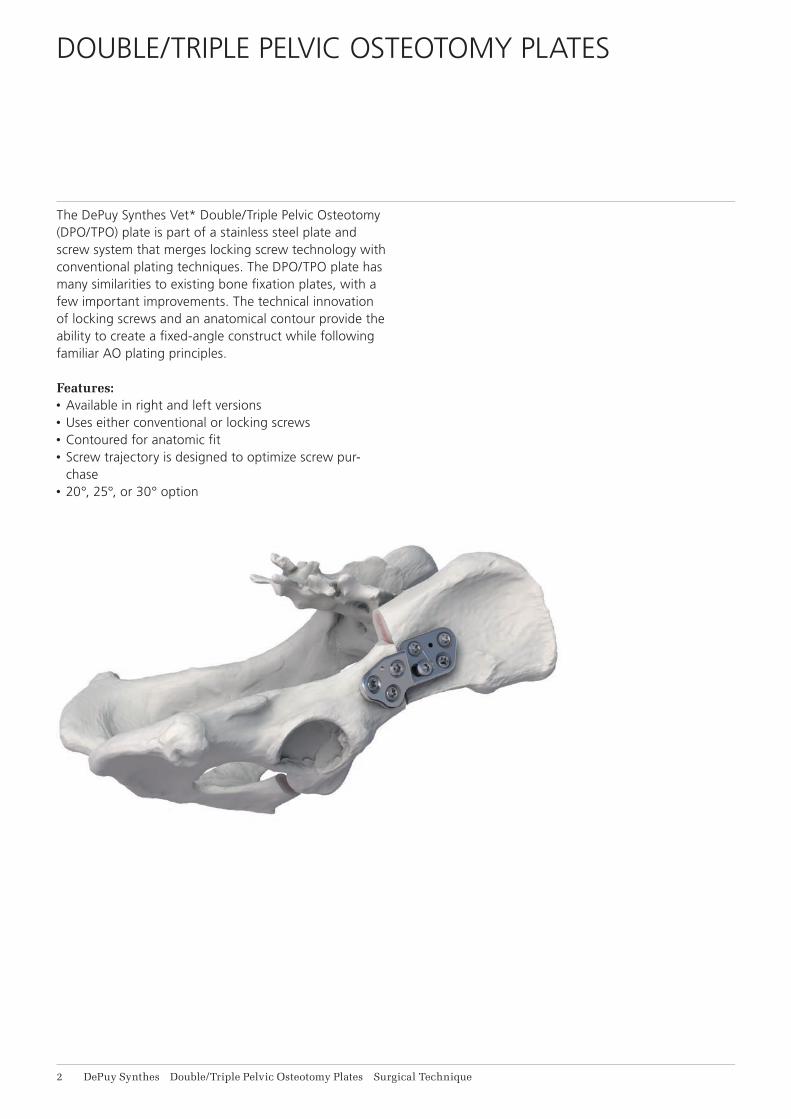
The DePuy Synthes Vet* Double/Triple Pelvic Osteotomy (DPO/TPO) plate is part of a stainless steel plate and screw system that merges locking screw technology with conventional plating techniques. The DPO/TPO plate has many similarities to existing bone fi xation plates, with a few important improvements. The technical innovation of locking screws and an anatomical contour provide the ability to create a fi xed-angle construct while following familiar AO plating principles.
Features: • Available in right and left versions• Uses either conventional or locking screws• Contoured for anatomic fi t• Screw trajectory is designed to optimize screw pur-
Screw HolesThe DePuy Synthes Vet DPO/TPO plate is designed with two distinct screw-hole technologies to accommodate all plating modalities. The plate includes three stacked Combi™ holes on the caudal side, and three stacked Combi holes and one locking compression plate (LCP)® Combi hole on the cranial side.
The stacked Combi hole in the plate accepts either cor-tex or locking screws. If locking screws are to be used in conjunction with cortex screws on the same side of the plate, the cortex screws must be inserted and tightened fi rst, before any locking screws are inserted.
The LCP Combi hole accepts either cortex screws or lock-ing screws. The cortex screw should be placed in the un-threaded portion of the Combi hole in either a loaded or neutral position. Alternatively, a locking screw may be used in the threaded portion of the Combi hole when indicated.
Fixed-angle StabilityThe threads on the head of the locking screws lock into
the threaded plate holes to form a fi xed-angle construct that will increase load transfer between the plate and bone. When compared to conventional plate-and-screw constructs, the angular and axial stability of locking screws increases the strength of the construct under load without requiring precise anatomical contouring.
Anatomical ContourThe anatomically shaped DPO/TPO plate is contoured to match the ilial shaft and to allow clearance for acetabu-lar fl are and the tuberosity for the rectis femoris muscle origin.
Triple/Double Pelvic Osteotomy Plates
PLATE DESIGN
Stacked Combi holes accept locking or cortex screws
Caudal
Optimized screw angulations
Kirschner Wire holes for temporary stabilization (1.6 mm)
Ability to perform either TPO or DPO with the same plate
Screw HeadThe tapered, double-lead machine thread on the head of the locking screw engages the threads of the locking plate holes. The resulting fi xed-angle construct provides stable fi xation of the bone fragments without having to compress the plate to the bone. A perfectly contoured plate is therefore not required to achieve fi xation and maintain proper alignment.
Thread ProfileBecause locking screws do not compress the plate to the bone, the “pull-out” mode of failure is not applicable to locking screws. For this reason, locking screws are made with a smaller thread profi le and a larger core diameter. This results in increased mechanical strength over com-parably sized cortex screws1.
Drive MechanismThe StarDrive recess of a locking screw provides three signifi cant improvements over an internal hex drive. First, “stripping” of the screw head is minimized as a failure mode, which results in a much higher tolerance to wear for the screwdriver1. Second, the tapered StarDrive re-cess provides automatic screw retention without the need for an additional screw holding mechanism. Third, the more effi cient StarDrive recess allows a smaller screw head and allows the screw head to sit fl ush with the plate.
Caution: • DePuy Synthes Companies of Johnson & Johnson
implants and instruments are manufactured with proprietary processes that produce superior prod-ucts to those created by conventional manufactur-ing processes. Though other companies may be able to estimate the DePuy Synthes Companies general product design, DePuy Synthes Companies product dimensions are proprietary. The precision design of DePuy Synthes Companies products is very important for long-term product function and optimal fi t between implants.
• Only the fi nest quality materials are used to man-ufacture DePuy Synthes Companies implants. The metals DePuy Synthes Companies uses have been scientifi cally proven to be of the best biocompati-bility and quality available today.
• With these features and qualities, the mixing of DePuy Synthes Companies implants with the im-plants from other companies is not recommended. The overall performance may be compromised due to differences in design, chemical composition, mechanical properties, and quality.
• Given these qualities are trade-secret, no competi-tor of DePuy Synthes Companies can make a genu-ine claim “the same as DePuy Synthes Compa-nies.” Combining implants from other companies with DePuy Synthes Companies implants could re-duce product performance. Consequently, it is strongly recommended to not mix parts from dif-ferent manufacturers.
Triple/Double Pelvic Osteotomy Plates
LOCKING SCREWS
Double-lead locking threads mate with the threaded portion of the plate
In 1958, the AO formulated four basic principles, which have become the guidelines for internal fixation.1,2 They are:
Anatomic ReductionFracture reduction and fixation to restore anatomical re-lationships.
Stable FixationStability by fixation or splintage, as the personality of the fracture and the injury requires.
Preservation of Blood SupplyPreservation of the blood supply to soft tissue and bone by careful handling.
Early, Safe MobilizationEarly, safe mobilization of the part and patient
AO PRINCIPLES
1. Müller ME, Allgöwer M, Schneider R, Willenegger H. Manual of Internal Fixation: Techniques Recommended by the AO-ASIF Group. 3rd ed. Berlin: Springer-Verlag; 1991.
2. Rüedi TP, Buckley RE, Moran CG (eds). AO Principles of Fracture Management. 2nd ed. Stuttgart, New York: Thieme. 2007.
The DePuy Synthes Vet DPO/TPO plate is intended for treatment of coxofemoral joint instability and sublux-ation in immature dogs prior to onset of osteoarthritis.
Note: Avoid use in patients with preexisting condi-tions which could compromise the strength of the pelvic bone. DPO should be avoided in patients less than 5 months old and TPO should be avoided in pa-tients less than 6 months old.
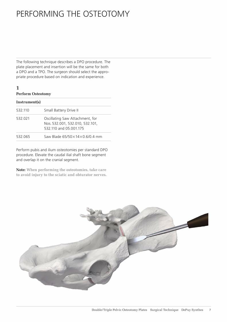
The following technique describes a DPO procedure. The plate placement and insertion will be the same for both a DPO and a TPO. The surgeon should select the appro-priate procedure based on indication and experience.
1Perform Osteotomy
Instrument(s)
532.110 Small Battery Drive II
532.021 Oscillating Saw Attachment, for Nos. 532.001, 532.010, 532.101, 532.110 and 05.001.175
532.065 Saw Blade 65/5021420.6/0.4 mm
Perform pubis and ilium osteotomies per standard DPO procedure. Elevate the caudal ilial shaft bone segment and overlap it on the cranial segment.
Note: When performing the osteotomies, take care to avoid injury to the sciatic and obturator nerves.
Align the ventral aspect of the caudal segment of the il-ial shaft and center the plate to optimize placement of the screws in the more robust bone of the ilial shaft.
Contour the plate as needed to match the natural curva-ture of the ilium. Plate contouring will alter the trajectory of the locking screws.
Apply caudal pressure when attaching the plate to the face of the caudal segment osteotomy to ensure place-ment of screws at a maximum distance from the osteot-omy. This pressure should be maintained when inserting screws. A Kirschner Wire can be used for temporary fixa-tion of the plate to the bone.
Note: When inserting implants, take care to avoid damage to the sciatic and obturator nerves.
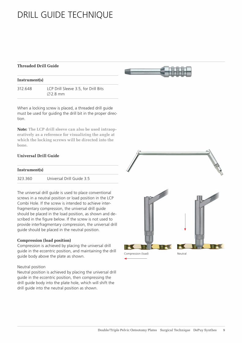
312.648 LCP Drill Sleeve 3.5, for Drill Bits B 2.8 mm
When a locking screw is placed, a threaded drill guide must be used for guiding the drill bit in the proper direc-tion.
Note: The LCP drill sleeve can also be used intraop-eratively as a reference for visualizing the angle at which the locking screws will be directed into the bone.
Universal Drill Guide
Instrument(s)
323.360 Universal Drill Guide 3.5
The universal drill guide is used to place conventional screws in a neutral position or load position in the LCP Combi Hole. If the screw is intended to achieve inter-fragmentary compression, the universal drill guide should be placed in the load position, as shown and de-scribed in the figure below. If the screw is not used to provide interfragmentary compression, the universal drill guide should be placed in the neutral position.
Compression (load position)Compression is achieved by placing the universal drill guide in the eccentric position, and maintaining the drill guide body above the plate as shown.
Neutral positionNeutral position is achieved by placing the universal drill guide in the eccentric position, then compressing the drill guide body into the plate hole, which will shift the drill guide into the neutral position as shown.
Refer to the DePuy Synthes Vet Small Fragment Tech-nique Guide for correct screw insertion techniques.
3Screw Insertion Order
The following technique is shown using the 3.5 mm DPO/TPO plate. It is recommended that screws be in-serted in the sequence described below:
Note: When using self-tapping screws, 2-3 mm can be added to the length to maximize thread pur-chase on the transcortex.
3aEnsure the plate is held firmly against the osteotomy by applying caudally directed pressure and insert a cortex screw in hole 1. This hole is angled slightly caudally away from the osteotomy to draw the plate to the bone when tightened, and to maximize the distance between the hole and the osteotomy.
3bPlace a locking screw in hole 2 and fully tighten.
3cIf a Kirschner Wire was used for temporary fixation in the caudal segment, it can be removed. Insert a locking screw in hole 3 and fully tighten.
3dRotate the caudal ilial segment with the threaded plate holder and/or pelvic forceps. The rotational force re-quired may be substantial depending on the age and size of the patient. The pressure on the instrument used for rotation should be maintained until the first screw is tightened to reduce the chance of stripping the screw hole.
Compress the plate against the ilial wing while also com-pressing the osteotomy. Compression of the osteotomy maintains the rotation, increases stability and speeds healing.
Insert a cortex screw in load position in hole 4 and com-press the plate to the ilial wing. This will simultaneously further compress the osteotomy.
If the cortex screw hole strips, the screw can be replaced with a locking screw once the plate is fully secured.
3eInsert the remaining screws holes 5, 6 and 7 and tighten fully. Screws can be placed in any order, based on sur-geon’s preference.
An additional cortex screw may be used to compress the plate against the ilium. It is recommended that at least 2 locking screws are used in the cranial segment due to the soft nature of the bone and the large loads placed on the screws.
Note: All screws must be fully tightened for proper function. Avoid over-tightening cortex screws as this may result in stripping the bone. Do not lock the screws to the plate under power. It is recom-mended that screw head thread engagement and fi-nal locking torque should be performed manually.
For 3.5 mm Locking Screws, 511.773 Torque Limiting At-tachment, 1.5 Nm, quick coupling can be used. Screws inserted with the Torque Limiting Adapter should be checked by hand to ensure they are fully tightened.
VW1603.15.10 Veterinary: Kirschner Wire B 1.6 mm with trocar tip, length 150 mm, Stain-less Steel, pack of 10 units
511.773 Torque Limiter, 1.5 Nm, for AO/ASIF Quick Coupling
324.023 Veterinary: Bending Pin for LCP Plates 3.5, with thread, length 100 mm
398.740 Pelvic Reduction Forceps, small, length 190 mm, for use with Cortex Screws B 3.5 and 4.5 mm
399.060 Reduction Forceps, toothed, speed lock, length 170 mm
Small Battery Drive II Accessories
05.001.204 Universal Battery Charger II
05.001.250 AO/ASIF Quick Coupling for Nos.
532.001, 532.010, 532.101, 532.110 and
05.001.175
532.104 Sterile Cover for Nos. 532.101 and
532.110
532.110 Small Battery Drive II
532.022 Quick Coupling for Kirschner Wires
B 0.6 to 3.2 mm, for Nos. 532.001,
532.010, 532.101 and 532.110
532.132 Battery Casing for Nos. 532.101 and
532.110, with Locking for Lid
532.021 Oscillating Saw Attachment, for Nos.
532.001, 532.010, 532.101, 532.110 and
05.001.175
532.103 Battery for Nos. 532.101 and 532.110
532.065 Saw Blade 65/5021420.6/0.4 mm
For the full range of attachments and accessories for the Small Battery Drive II, please contact your DePuy Synthes Vet representative or consult the DePuy Synthes Power Tools product catalog.
Note: Veterinary: Small Fragment Instrument Set (103.503) consists of Standard Instrument Set (103.501), with graphic case, and Locking Instru-ment Set (103.502).
For detailed cleaning and sterilization instructions, please refer to: www.synthes.com/cleaning-sterilizationIn Canada, the cleaning and sterilization instructions will be provided with the Loaner shipments.


![Case Report Journal of Orthopaedic Case Reports 2020 ...€¦ · [8], hip fusion [9], and pelvic supportive osteotomy [7]. Reviewing the literature and with patient approval, femoral](https://static.documents.pub/doc/80x56/60fb49b2c2c1962a9273aa57/case-report-journal-of-orthopaedic-case-reports-2020-8-hip-fusion-9-and.jpg)
