13
A UDLA Company A UDLA Company Douglas Lighting Controls Bluetooth ® Fixture Controller & Sensor BT-FMS-A Installation Manual *Patent Pending

A UDLA Company A UDLA Company
Douglas Lighting ControlsBluetooth® Fixture Controller & Sensor
BT-FMS-A
Installation Manual*Patent Pending
A UDLA Company A UDLA Company
WARNING!
SYSTEM MUST BE INSTALLED IN ACCORDANCE WITH LOCAL AND NATIONAL ELECTRICAL CODES
For use in wet/damp locations.
Risk of Electric Shock. All servicing should be performed by qualified service personnel. To reduce the risks of electric shock discon-nect power supplies before servicing.
Be aware that Line Voltage Connections may be 120VAC or 277VAC or 347VAC
IMPORTANT SAFEGUARDS
• READ AND FOLLOW ALL SAFETY INSTRUCTIONS.• Do not mount near gas or electric heaters.• Equipment should be mounted in locations and at heights where it will not readily be subjected to tampering by unauthorized
personnel.• The use of accessory equipment not recommended by the manufacturer may cause an unsafe condition.• Do not use this equipment for other than intended use
• Wireless devices are only for lighting control• Wireless controls cannot be used with portable heating appliances
• Insulate unused leads individually
SAVE THESE INSTRUCTIONS
Page 2
A UDLA Company A UDLA Company
1. INTRODUCTION Page 4
1.1. GENERAL DESCRIPTION Page 4
2. DESIGN FEATURES Page 4
3. SPECIFICATIONS Page 5
MOUNTING Page 5
POWER Page 5
LOAD RATINGS Page 5
WIRELESS RANGE Page 5
OPERATING ENVIRONMENT Page 5
APPROVALS: Page 5
WARRANTY Page 5
4. DIMENSIONS Page 6
5. COVERAGE Page 7
6. INSTALLATION FEATURES Page 7
7. INSTALLATION / WIRING Page 7
8. SYSTEM LAYOUT & DESIGN Page 9
Table of Contents
Page 3

A UDLA Company A UDLA Company
1. INTRODUCTION
2. DESIGN FEATURES
1.1. General DescriptionThe Douglas Lighting Controls Bluetooth® Fixture Controller & Sensor (FMS) provides automated individual and group control of light fixtures using onboard sensors and Bluetooth technology. It is easily installed for ON/OFF or bi-level light functionality. The daylight sensor provides additional energy savings by dimming the lights when natural daylight is available in open-sided parking garages or from windows.
Configuration of the Douglas Lighting Controls Fixture Controller & Sensor is done conveniently at deck level with our Smartphone App using the Bluetooth protocol to communicate with the device. A wireless mesh network is created between devices for control over a group of Douglas Lighting Controls Bluetooth equipment.
The BT-FMS-A has a maximum vertical range of 40 feet and is powered from the fixture. It is tested to applicable UL and CSA standards and enables users to meets ASHRAE 90.1 and Title 24 energy code requirements. After configuring the devices, the system will automatically operate to control lighting based on occupancy in the area and the system settings.
Typical Applications: Parking Garages, Warehouses, Manufacturing Facilities.
NOTE: The instructions in this manual apply to version v1.20 and higher. This version of the FMS is part of the Douglas Bluetooth ecosystem and can be integrated into projects using switches and other Douglas BT devices. The version number is provided as the top line of the FMS configuration screen, which is described in the following pages.
Prior versions of the FMS were not suitable for integration with other Douglas BT components and are not addressed in this manual.
• Bluetooth Wireless Technology• Occupancy sensor• Daylight sensor• Relay• 360° coverage pattern• Water-tight/waterproof design (IP65)• 0-10V dimming, daylight harvesting, bi-level set-points, ON/OFF• Deck level system set-up using iOS smartphone app
Page 4
A UDLA Company A UDLA Company
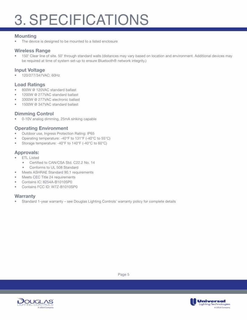
3. SPECIFICATIONSMounting• The device is designed to be mounted to a listed enclosure
Wireless Range• 150’ Clear line of site. 50’ through standard walls (distances may vary based on location and environment. Additional devices may
be required at time of system set-up to ensure Bluetooth® network integrity.)
Input Voltage• 120/277/347VAC; 60Hz
Load Ratings• 800W @ 120VAC standard ballast• 1200W @ 277VAC standard ballast• 3300W @ 277VAC electronic ballast• 1500W @ 347VAC standard ballast
Dimming Control• 0-10V analog dimming, 25mA sinking capable
Operating Environment• Outdoor use, Ingress Protection Rating: IP65• Operating temperature: -40°F to 131°F (-40°C to 55°C)• Storage temperature: -40°F to 140°F (-40°C to 60°C)
Approvals: • ETL Listed
• Certified to CAN/CSA Std. C22.2 No. 14• Conforms to UL 508 Standard
• Meets ASHRAE Standard 90.1 requirements• Meets CEC Title 24 requirements• Contains IC: 8254A-B1010SP0• Contains FCC ID: W7Z-B1010SP0
Warranty• Standard 1-year warranty – see Douglas Lighting Controls’ warranty policy for complete details
Page 5

A UDLA Company A UDLA Company
4. DIMENSIONS
39.
25m
m1.
55in
6
.30m
m0.
25in
8
1.12
mm
3.19
in
141.06mm5.55in
89.56mm3.53in
23mm0.91in
106.06mm4.18in
23mm0.91in
58mm2.28in
35.32mm1.39in
39.
25m
m1.
55in
6
.30m
m0.
25in
8
1.12
mm
3.19
in
141.06mm5.55in
89.56mm3.53in
23mm0.91in
106.06mm4.18in
23mm0.91in
58mm2.28in
35.32mm1.39in
39.
25m
m1.
55in
6
.30m
m0.
25in
8
1.12
mm
3.19
in
141.06mm5.55in
89.56mm3.53in
23mm0.91in
106.06mm4.18in
23mm0.91in
58mm2.28in
35.32mm1.39in
Spacer
Spacer
Threaded chase nipple break point for overhangs less than ½” (12mm).
Page 6

A UDLA Company A UDLA Company
5. COVERAGE
20ʼ 30ʼ 40ʼ0ʼ 10ʼ10ʼ20ʼ30ʼ40ʼ
40 ft
30 ft
20 ft
0 ftSIDE VIEW40 ft
18 ft
0 ft
0 ft
18 ft
40 ft
40 ft18 ft18 ft40 ft
6. INSTALLATION FEATURES
7. INSTALLATION / WIRING
The device is designed to be mounted into a ½” knockout in a listed light fixture or electrical junction box or panel with an opening that can fit the threaded chase nipple.
• Thoughtful design to maximize sensor coverage range• Bluetooth enabled for deck level configuration and wireless mesh networking
• Douglas Lighting Controls Bluetooth Fixture Controller & Sensor mounts directly into a standard 1/2” knockout• If fixture overhang is greater than ½” then use full length chase nipple and spacer. For overhang less than ½” the chase nipple
length can be reduced by using needle nose pliers to snap the extension at the break point (see diagram on next page).• Install device into position (use spacer if fixture overhang is greater than ½”)• For installation with field installed conductors of 60°C minimum rating.• The following wire connections are provided:
• 0-10V connection (violet / grey): #20AWG• Line Voltage/Relay connection (black / white / red): #14AWG
• Connect wires as shown on diagram• Use appropriate sized wire-nuts to connect field installed conductors• System programming and configuration > see System Set-up section
CAUTION Risk of Electric Shock. All servicing should be performed by qualified service personnel. To reduce the risks of electric shock disconnect power connections before servicing.
! !
Page 7

A UDLA Company A UDLA Company
39.
25m
m1.
55in
6
.30m
m0.
25in
8
1.12
mm
3.19
in
141.06mm5.55in
89.56mm3.53in
23mm0.91in
106.06mm4.18in
23mm0.91in
58mm2.28in
35.32mm1.39in
39.
25m
m1.
55in
6
.30m
m0.
25in
8
1.12
mm
3.19
in
141.06mm5.55in
89.56mm3.53in
23mm0.91in
106.06mm4.18in
23mm0.91in
58mm2.28in
35.32mm1.39in
39.
25m
m1.
55in
6
.30m
m0.
25in
8
1.12
mm
3.19
in
141.06mm5.55in
89.56mm3.53in
23mm0.91in
106.06mm4.18in
23mm0.91in
58mm2.28in
35.32mm1.39in
MountingUse Spacer and full length threaded chase nipple for fixture rail overhang greater than ½” (12mm).
Red – relay/loadBlack – hot/lineWhite - neutral
GrayViolet 0-10V dimming
Spacer
Spacer
Threaded chase nipple break point for overhangs less than ½” (12mm).
Fixture rail
Wiring
7. INSTALLATION / WIRING
Page 8

A UDLA Company A UDLA Company
Before You Start• A best practise is to use a dedicated iPod or iPhone as the project’s system set-up device rather than a personal smartphone as
the system settings stay with the Apple ID.• When setting up the iOS device Apple ID, iCloud account, and network access, chose names carefully, record accurately, and
store in a reliable location.• Once a Fixture Controller & Sensor has been added to a network (associated), do not remove (disassociate) it before ensuring it is
connected to, and communicating with, the system set-up device.
System Set-Up Overview
The system set-up deviceEach lighting control installation requires an iOS device and an iCloud account to be used for system set-up and storing system parameters. Acceptable devices include:• iPod Gen 6 or newer and iOS 10.x or higher• iPhone 6 or newer and iOS 10.x or higherDouglas Lighting Controls recommends using a project-dedicated device, not one which is used for personal and/or other company data and communications. Details on iCloud accounts, including instructions for setup, can be found at www.apple.com/icloud.
An iOS device with iCloud account is needed to download the App and to back up the system parameters on iCloud. Each iCloud account can have only one instance of the App, and the App can create and maintain only one database. A database stores the system parameters. The database is identified by the Network Key and accessed using the Admin Password (both values are entered during system set-up).
Description of the system set-up process
After an iOS device is configured with an iCloud account and the App downloaded, the system set-up process can begin. First, system parameters are entered. These include:
• Site Name• Network Key• Admin Password
Record this information accurately and store in a reliable location. These parameters are critical to accessing the system. A good method for recording this information is screen capture the network setup page. To take a screen shot, press and hold the ON/OFF button, then momentarily press the Home button. The screen capture will be saved as an image accessible via the Photos icon. The screen capture can then be emailed to a few people for recovery purposes. Again, it is very important to keep track of this data and of the iOS device itself.
After the system network parameters are established, typical system set-up steps will be:• Finding unassociated Douglas Lighting Controls Bluetooth devices• Associating an FMS to the Network• Creating “rooms” for the project• Completing the FMS setup• Adding and setting up additional BT-FMS-A and other Douglas Lighting Controls Bluetooth devices
8. SYSTEM LAYOUT & DESIGN
Page 9

A UDLA Company A UDLA Company
Spatial organization
A Douglas Lighting Controls Bluetooth wireless network can have multiple rooms and each room can have up to eight lighting zones. Rooms and Zones are defined in the system set-up. Review your floor plans to find, and if needed, develop a room and zone plan
Settings
• Occupancy control parameters are configured at the room level and apply to all Bluetooth devices in the room.• Minimum and maximum dimming boundaries (high and low trim) are set at the zone level and apply to all devices in the zone.• Zone assignments and daylighting control parameters (if used) are set at the FMS level and are similar to those for the BT-IFS-A.
Refer to the BT-APP manual for further instruction on these settings.• In addition, daylight settings can be set to “Self” for localized Daylight Harvesting.• Instant On is a unique feature of the FMS.
When disabled, the FMS interacts with other elements of the Bluetooth network much like the BT-IFS-A. For example, it will permit manual override to OFF with a BT switch.
When enabled this feature will prioritize the FMS’ local occupancy control over commands coming from the BT network. That is, occupancy detection will force turn ON, even when external commands request turn OFF.
Device compatibility
The instructions in this manual apply to version 1.2 and higher. This version of the BT-FMS-A is part of the Douglas Bluetooth ecosys-tem and can be integrated into projects using switches and other Douglas BT devices. The version number is provided as the top line of the FMS configuration screen, which is described in the following pages.
Prior versions of the FMS were not suitable for integration with other Douglas BT components and are not addressed in this manual.
Preparation for a system set-up project
System set-up will progress quickly with up-front planning. Creating a plan for how to name and configure each device will save time and provide useful elements for documenting the project at its conclusion. A simple example is outlined in the three figures below.
8. SYSTEM LAYOUT & DESIGN
Page 10
A UDLA Company A UDLA Company
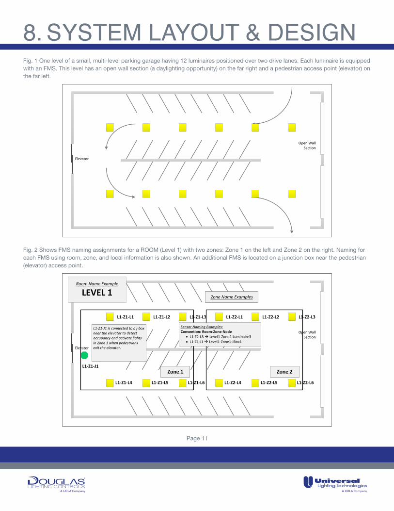
Fig. 2 Shows FMS naming assignments for a ROOM (Level 1) with two zones: Zone 1 on the left and Zone 2 on the right. Naming for each FMS using room, zone, and local information is also shown. An additional FMS is located on a junction box near the pedestrian (elevator) access point.
Fig. 1 One level of a small, multi-level parking garage having 12 luminaires positioned over two drive lanes. Each luminaire is equipped with an FMS. This level has an open wall section (a daylighting opportunity) on the far right and a pedestrian access point (elevator) on the far left.
Elevator
Open WallSection
Elevator
Open WallSection
L1-Z1-J1 is connected to a j-box near the elevator to detect occupancy and activate lights in Zone 1 when pedestrians exit the elevator.
L1-Z1-L1 L1-Z1-L2 L1-Z1-L3 L1-Z2-L1 L1-Z2-L2 L1-Z2-L3
L1-Z1-L4 L1-Z1-L5 L1-Z1-L6 L1-Z2-L4 L1-Z2-L5 L1-Z2-L6
L1-Z1-J1
Zone Name Examples
Zone 1
Room Name Example
LEVEL 1
Zone 2
Sensor Naming Examples:Convention: Room-Zone-Node
· L1-Z2-L3 à Level1-Zone2-Luminaire3· L1-Z1-J1 à Level1-Zone1-JBox1
8. SYSTEM LAYOUT & DESIGN
Page 11
A UDLA Company A UDLA Company
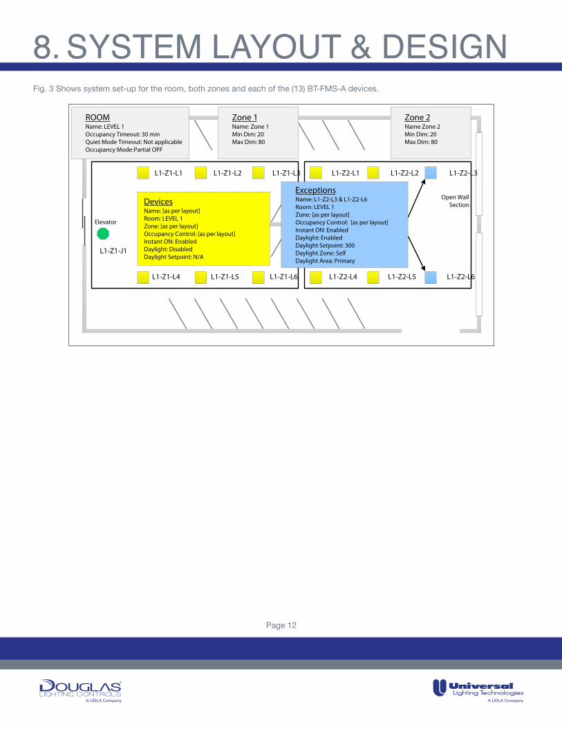
Fig. 3 Shows system set-up for the room, both zones and each of the (13) BT-FMS-A devices.
Elevator
Open WallSection
L1-Z1-L1 L1-Z1-L2 L1-Z1-L3 L1-Z2-L1 L1-Z2-L2 L1-Z2-L3
L1-Z1-L4 L1-Z1-L5 L1-Z1-L6 L1-Z2-L4 L1-Z2-L5 L1-Z2-L6
L1-Z1-J1
ROOMName: LEVEL 1Occupancy Timeout: 30 minQuiet Mode Timeout: Not applicable Occupancy Mode: Partial OFF
Zone 1Name: Zone 1 Min Dim: 20 Max Dim: 80
Zone 2Name Zone 2 Min Dim: 20 Max Dim: 80
Devices Name: [as per layout] Room: LEVEL 1Zone: [as per layout]Occupancy Control: [as per layout]Instant ON: EnabledDaylight: DisabledDaylight Setpoint: N/A
Exceptions Name: L1-Z2-L3 & L1-Z2-L6Room: LEVEL 1Zone: [as per layout]Occupancy Control: [as per layout]Instant ON: EnabledDaylight: EnabledDaylight Setpoint: 300Daylight Zone: SelfDaylight Area: Primary
8. SYSTEM LAYOUT & DESIGN
Page 12

A UDLA Company A UDLA Company
The Bluetooth® word mark and logos are registered trademarks owned by the Bluetooth SIG, Inc. and any use of such marks by Douglas Lighting Controls is under license.Other trademarks and trade names are those of their respective owners.
LIT#: BT-FMS-AFC&SM021721
toll free: 877-873-2797direct: 604-873-2797lighting@douglaslightingcontrols.comwww.douglaslightingcontrols.com
Your Douglas Lighting Controls representative:


