Transportation Research Record 1062 47 Dowel Placement Tolerances for Concrete Pavements SHIRAZ D. TAYABJI ABSTRACT The results of an investigation conducted to develop placement tolerances for dowels at concrete pavement joints are presented. A theoretical analysis of dowel misalignment was attempted. The purpose of the analysis was to compute restraint stresses induced in the concrete pavement for different levels of dowel misalignment. However, because of the complexity of correctly incorporat- ing the three-dimensional nature of dowel misalignment, the theoretical analysis was not completed. The effect of dowel misalignment was then investigated in the laboratory by conducting pullout tests on sections of concrete slabs in- corporating a joint and dowels with different levels of misalignment. Test re- sults are presented that indicate that pullout loads were relatively low for dowel misalignment levels of less than 1 in. per 18-in. length of dowel bar and a maximum joint opening of 0.25 in. Joints are provided in concrete pavements to control transverse and longitudinal cracking that results from restrained deformations caused by moisture and temperature variations in the slab. Because joints create a discontinuity in the pavement, use of joints may reduce load-carrying capacity of the pavement at the joint. To ensure adequate load transfer, load- transfer devices are used at joints by many highway agencies. Current practice for load-transfer devices at joints has evolved over a period of time. Some of the systems used have included the I-beam, Starlug, two-component devices, and round steel dowel bars. Today, round steel dowel bars are the most widely used. Current recommended practice for doweled joints is for dowel diameters to be one-eighth of slab thickness, dowel spacing to be 12 in., and dowel length to be 18 in. Dowel bars require care in placement to minimize detrimental effects of misalignment. It is generally specified that dowels be placed as much as is prac- tical parallel to the longitudinal axis and the horizontal plane of the pavement. Generally, limits on permissible tolerances are specified individually by state highway agencies. The different categories of dowel misalignment and their possible effects on pavement behavior are illustrated in Figure 1. Before December 1980, FHWA specified limits on dowel placement (1). However, the current FHWA Tech- nical Advisory TS140.18 of December 15, 1980, on rigid pavement joints does not specify limits on misalignment but cautions that "close tolerances for dowel placement are extremely important for proper functioning of the slab and for long-term perfor- mance" This advisory also states that "care must be exercised in both specifying dowel placement tolerance and in evaluating the adequacy of con- struction placement" <!!). In the past, an alignment error of 1/ 4 in. per 18-in. length of dowel has been considered accept- able. However, many state highway agencies specify different permissible levels of misalignment. For example, the Illinois Department of Transportation specifies in their Standard Specifications for Road and Bridge Construction, dated October 1979, that Construction Technology Laboratories, Portland Cement Association, 5420 Old Orchard Road, Skokie, Ill. 60077. any deviation from correct alignment greater than 1/8 in. in 12 in. should be corrected before any concrete is placed. The Georgia Department of Trans- portation specifies an allowable tolerance of 3/8 in. per foot in both the horizontal and vertical directions. No clear consensus exists as to the level of practical limits on dowel placement tolerances. When limits are specified, contractors often state that they are neither practical nor realistic. In addi- tion, it is a slow process to determine levels of misalignment once the pavement has been constructed. Attempts have been made to measure levels of mis- alignment by using radar devices or by using a pachometer and taking partial-depth or full-depth cores near the ends of the dowel. The primary reason for placing limits on dowel placement tolerance is to minimize problems asso- ciated with locked joints. Pavement slabs should be free to expand and contract with changes in slab temperature and moisture. Resistance to movement is provided by subbase friction and locked joints. For slabs up to 40 ft, resistance due to subbase friction is not as significant. The magnitude of restraint due to locked joints depends on the degree of dowel misalignment, number of misaligned dowels, and dowel corrosion. Locked joints may result in transverse cracking, corner breaks, and spalling at the concrete face around the dowel. Once a spall occurs around a dowel, load- tr ansfer effectiveness of the dowel may decrease. STUDY OBJECTIVES The investigation reported in this paper was under- taken to study the effects of dowel misalignment on pavement performance. Specific objectives were as follows: 1. To use analytical methods to perform stress analysis of the joint system incorporating dowels with different levels of misalignment, 2. To conduct laboratory tests to determine the effect of dowel misalignment, and 3. To select placement tolerance criteria based on study results.
Transcript
Transportation Research Record 1062 47
Dowel Placement Tolerances for Concrete Pavements SHIRAZ D. TAYABJI
ABSTRACT
The results of an investigation conducted to develop placement tolerances for dowels at concrete pavement joints are presented. A theoretical analysis of dowel misalignment was attempted. The purpose of the analysis was to compute restraint stresses induced in the concrete pavement for different levels of dowel misalignment. However, because of the complexity of correctly incorporating the three-dimensional nature of dowel misalignment, the theoretical analysis was not completed. The effect of dowel misalignment was then investigated in the laboratory by conducting pullout tests on sections of concrete slabs incorporating a joint and dowels with different levels of misalignment. Test results are presented that indicate that pullout loads were relatively low for dowel misalignment levels of less than 1 in. per 18-in. length of dowel bar and a maximum joint opening of 0.25 in.
Joints are provided in concrete pavements to control transverse and longitudinal cracking that results from restrained deformations caused by moisture and temperature variations in the slab. Because joints create a discontinuity in the pavement, use of joints may reduce load-carrying capacity of the pavement at the joint. To ensure adequate load transfer, loadtransfer devices are used at joints by many highway agencies.
Current practice for load-transfer devices at joints has evolved over a period of time. Some of the systems used have included the I-beam, Starlug, two-component devices, and round steel dowel bars. Today, round steel dowel bars are the most widely used. Current recommended practice for doweled joints is for dowel diameters to be one-eighth of slab thickness, dowel spacing to be 12 in., and dowel length to be 18 in.
Dowel bars require care in placement to minimize detrimental effects of misalignment. It is generally specified that dowels be placed as much as is practical parallel to the longitudinal axis and the horizontal plane of the pavement. Generally, limits on permissible tolerances are specified individually by state highway agencies. The different categories of dowel misalignment and their possible effects on pavement behavior are illustrated in Figure 1.
Before December 1980, FHWA specified limits on dowel placement (1). However, the current FHWA Technical Advisory TS140.18 of December 15, 1980, on rigid pavement joints does not specify limits on misalignment but cautions that "close tolerances for dowel placement are extremely important for proper functioning of the slab and for long-term performance" (~). This advisory also states that "care must be exercised in both specifying dowel placement tolerance and in evaluating the adequacy of construction placement" <!!).
In the past, an alignment error of 1 / 4 in. per 18-in. length of dowel has been considered acceptable. However, many state highway agencies specify different permissible levels of misalignment. For example, the Illinois Department of Transportation specifies in their Standard Specifications for Road and Bridge Construction, dated October 1979, that
Construction Technology Laboratories, Portland Cement Association, 5420 Old Orchard Road, Skokie, Ill. 60077.
any deviation from correct alignment greater than 1/8 in. in 12 in. should be corrected before any concrete is placed. The Georgia Department of Transportation specifies an allowable tolerance of 3/8 in. per foot in both the horizontal and vertical directions.
No clear consensus exists as to the level of practical limits on dowel placement tolerances. When limits are specified, contractors often state that they are neither practical nor realistic. In addition, it is a slow process to determine levels of misalignment once the pavement has been constructed. Attempts have been made to measure levels of misalignment by using radar devices or by using a pachometer and taking partial-depth or full-depth cores near the ends of the dowel.
The primary reason for placing limits on dowel placement tolerance is to minimize problems associated with locked joints. Pavement slabs should be free to expand and contract with changes in slab temperature and moisture. Resistance to movement is provided by subbase friction and locked joints. For slabs up to 40 ft, resistance due to subbase friction is not as significant.
The magnitude of restraint due to locked joints depends on the degree of dowel misalignment, number of misaligned dowels, and dowel corrosion. Locked joints may result in transverse cracking, corner breaks, and spalling at the concrete face around the dowel. Once a spall occurs around a dowel, loadtr ansfer effectiveness of the dowel may decrease.
STUDY OBJECTIVES
The investigation reported in this paper was undertaken to study the effects of dowel misalignment on pavement performance. Specific objectives were as follows:
1. To use analytical methods to perform stress analysis of the joint system incorporating dowels with different levels of misalignment,
2. To conduct laboratory tests to determine the effect of dowel misalignment, and
3. To select placement tolerance criteria based on study results.
48
Plan View
11
'• 1, Joint 11
11
•• II u
Plan View ---.;-11 11 11
Jojnt : 1
II II u
'l'ransportation Research Record 1062
Section
Joint
•
(a) Horizontal Translation
(b) Longitudinal Translation
(c) Vertical Translation
Type of
Plan View n , ,
I 1,
'"'
/
(d) Horizontal Ske w
Misalignment Spalling
a -b -
c Yes
d Yes
e Yes
Section
_, i "~'.
(el Vertical Skew
Effect on
Load Cracking Transfer
- (Yes)•
- (Yes)*
- (Yes)*
Yes Yes
Yes Yes
*Effect will depend on amount of translation
FIGURE 1 Effects of dowel misalignment.
FACTORS AFFECTING DOWEL MISALIGNMENT
The following factors affect level of dowel misalignment when basket assemblies are used:
1. Basket rigidity, 2. Quality control during basket fabrication, 3. Care during basket transportation and place-
ment, 4. Fastening of basket to subbase, 5. Location of saw cut over basket, 6. Paving operation (the large roll of concrete
ahead of the paver may displace individual dowels or the basket assembly) , and
7. Field inspection during construction.
The following factors affect level of dowel misalignment when dowels are implanted:
1. Implanting machine operation, 2. Strike-off after dowel placement, 3. Consolidation (vibration) after dowel place
ment, 4. 5.
Location of saw cut over implanted dowels, and Field inspection during construction.
For basket assemblies, basket rigidity and proper fastening of the basket assembly to the subbase are er i tical. Even a small movement or rotation of the basket assembly during the paving operation is sufficient to cause noncompliance of dowel placement.
For implanted dowels, different paving sequences have been used to achieve proper placement of dowel bars. Some paving sequences used strike-off and concrete consolidation (internal vibration) operations following dowel placement. In other paving operations, concrete consolidation after dowel placement was not used (l). However, degree of compliance with allowable dowel placement tolerances has been reported as unsatisfactory for all these procedures (_2.) •
The amount of misalignment that can be tolerated greatly depends on joint spacing and climate. Greater misalignment can be tolerated if the need for joint movement (opening) is not large. The magnitude of restraint due to locked joints depends on the degree of load-transfer device misalignment as well as dowel corrosion. As indicated in Figure 1, excessive restraint to slab movement may result in transverse and corner cracking and spalling at the concrete face around the dowel. Sample calculations of restraint that needs to be developed to cause midslab cracking are presented in Table 1.
BACKGROUND
Only a few investigations have been conducted to study levels and effects of dowel misalignment. The number of field investigations has been limited because of lack of practical methods for evaluating alignment of dowels in place.
Tayabji
TABLE 1 Calculated Restraint to Cause Midslab Cracking in 10-in.-Thick Slab
Concrete Restraint Tensile Compressive Modulus Allowable to Cause
Note: (a) Before mid slab crocking occu rs, spnlling may take place around load-transfer device. (b) Tensile st ress in the form of curling restraint st ress and load stress also exists. Therefore, even a reduced level of restraint can contribute significantly to crack formation. (c) Age, strength, and modulus relationships are genera l and are used for illustration only.
An early field study conducted in Indiana by Smith and Benham found a large number of misaligned dowels (4). As a supplement to the field work, laboratory t;sts were conducted using small slab sections incorporating a joint and dowels spaced at 12-in. centers. In these tests, 3/ 4-in.-diameter dowels were pl3ced at different levels of misalignment and loading was applied at 28 days to open the joint. Results indicated that for a 6-in.-thick slab section, an alignment error in excess of 1 in. caused spalling when joints were opened 3/ 4 in. For a 5-in.-thick slab section, an alignment error of 1/4 in. caused slight spalling. Test results also showed that if the joint was not opened more than 1/ 2 in., alignment errors up to 1 1/2 in . could be tolerated without spalling. Generally, the load required to open a contraction joint 1/ 2 in. did not exceed 3 ,000 lb per dowel.
In another study, conducted by Segner and Cobb at the University of Alabama, slab sections 5 ft wide, 5 1/ 2 ft long, and 10 in. thick were used (2) • Dowels used were 1 1/4 in. in diameter and 16 in. long. Testing was done at 2 and 7 days. Load required to open a joint 1/ 2 in. for a 1-in. vertical misalignment of a dowel was about 4,000 lb, and for a 1-in. horizontal misalignment of a dowel the load was about 2,000 lb. Spalling was produced for a vertical misalignment of 1 in. or for a horizontal misalignment of 3 in. at a joint opening of about 0.9 in.
Theoretical effects of misalignment have been studied by Friberg ( 6) and Weaver and Clark (2) • Friberg assumed that i~ a misaligned dowel, the dowel deflection must equal the transverse component of the movement in a parallel displacement of - the slab. The relationship between the deflection of the dowel and dowel misalignment was then determined by Friberg as follows (§) :
()i = {{P/2EI) [(l + Ba) 2 /B'J + (a'/6)}
where
~ misalignment of the dowel in the direction of slab movement (rad),
i total slab end movement, a total joint width, P dowel shear developed due to misalignment, E modulus of elasticity of dowel steel, I moment of inertia of dowel section, B relative stiffness of dowel and concrete
(GD/4EIJ 1/ 4 I
G modulus of dowel concrete reaction, and D dowel diameter.
(1)
With this equation, dowel shear developed due to misalignment can be calculated. The calculated shear values can then be used to compute concrete bearing stresses under dowels. Shear loads calculated by
49
using the equation are given in Table 2 for a 1 percent dowel misalignment and different levels of slab end movements. However, this analysis considers only dowel bearing effects and not the effects of dowel slippage or the resistance to dowel movement of the concrete surrounding the dowel. The analysis does not provide information on development of tensile stress in the pavement slab as a result of dowel misalignment.
TABLE 2 Dowel Shear Induced due to Misalignment of 1 Percent (6)
Dowel Final Joint Dowel Shear Induced {lb) Diameter Width(ai) (in.) (in.) i = 0.25 in. i = 0.50 in.
1. 00 0.2S 815 1,630 0.50 695 1,390
1. 25 0.2S l,235 2,465 0.50 1,090 2,175
Note: i =change in joint width due to slab end movement.
Recent investigations have concentrated on comparing misalignment levels ~nd performance of joints having machine-implanted dowels and preset basket assemblies (~-.!_Q_J • These studies have been conducted because of concern about dowel placement accuracy when machine implanters are used. In the Pennsylvania study (,~), horizontal, vertical, and longitudinal misalignments were measured at implanted and conventionally placed dowel bar joints. Two bars each from five joints were chosen for each placement type. A pachometer was used to locate the dowels and 4-in.diameter cores were drilled to the top of the bars at each end of the bar. The average values of misalignment are given in Table 3. Sixty percent of the implanted dowels and 40 percent of conventionally placed dowels were outside specified limits of tolerance. The Pennsylvania Department of Transportation specifies an allowable tolerance of 1/4 in. per 18-in. length of dowel bar in both the horizontal and vertical directions.
In an investigation conducted for the American Concrete Pavement Association, visual surveys and misalignment determinations using a metal detector
TABLE 3 Levels of Misalignment Measured in the Field (8)
Basket 2E 5/8 1/4 0 1-3/8 2E 1/8 0 3/8 I 6E 7/16 0 l/32 I 6E I /16 0 5/16 1-1/4 9E 1/16 0 7/16 I 9E 1/16 1/8 7 /16 15-16
!SE 3/8 1/4 1/16 5/8 !SE 1/16 1/4 1-1/4 3/8 17E 1/8 3/8 11 /16 11 /16 17E 0 0 I 1/16 1/8
Implanted I 1/16 1/4 I l/16 7/8 I I /16 1/4 3/4 7 /8 2 1/16 3/16 7 /16 5/16 2 3/16 0 3/4 1/4 9 3/16 3/8 5/8 5/16 9 1/8 3/8 5/8 7/16
19 1/16 3/4 15/16 3/8 19 I /16 1/4 3/4 3/8 28 I /16 1/4 l-3/16 1/8 28 ! /8 0 I 0
Note: Spedfied tolerances For these projects were a skew of l /4 in. per 18 in. length of dowel bar in both the vertical and horizontal directions and a verlical or horizontal translation of ±1 in.
50
were made at several sites in Alabama to compare joints with mechanically implanted and conventionally placed dowels (~). Projects studied were constructed between 1958 and 1969. A statistical analysis was conducted to identify trends. It was found that there was no significant difference between implanted and preset dowel joints with respect to joint-related distress. However, no statistically valid conclusions could be drawn from the misalignment data.
In a Tennessee investigation (10), misalignment levels were determined at several sites by uncovering dowels in freshly placed plastic concretP. and by core drilling in hardened concrete. On the basis of the findings, it was recommended that horizontal and vertical skew tolerances be 1/2 in., vertical tolerance be ±1 in., and longitudinal tolerance be ±1 1/2 in.
In a study conducted during 1982 by the Georgia Department of Transportation, dowel bar placement was investigated at five highway projects <ll· Three projects had implanted dowels and two projects had used dowel basket assemblies. Project details are given in Table 4. Dowel placement was determined by coring and use of a metal detector. In addition, distress at joint locations was observed. A total of 261 joints were evaluated in detail and another 400 to 500 joints were examined for signs of distress.
A summary of Georgia's field evaluation is given in Table 5. It is clear from Table 5 that there is substantial noncompliance with the specification requirement for the projects with the implanted dowels. However, no dowel-related distress was found in any of the joints that were examined <l>· In addition, it was reported that during construction of the five projects, all joints had started "working" within a few days of construction. However, because of the noncompliance problem with implanted dowels, the study recommended that implanting of dowels not be allowed. The study also recommended that improvements be made in methods and equipment for implanting dowels and that studies be conducted to determine permissible levels of dowel misalignment.
ANALYTICAL MODELING
Analytical modeling was used to perform stress analysis of joint systems incorporating dowels with dif-
Transportation Research Record 1062
ferent levels of misalignment. The following items were considered in the analysis:
1. Slippage between dowel and concrete, 2. Simulation of temperature drop in the concrete
slab, and 3. Dowel misalignment levels.
An analysis was conducted to simulate slab end movement due to temperature change within the slab. Restraint to slab end movement would be induced by the misaligned dowels. One of the difficulties in an analysis of a doweled system is the complexity of modeling the slip between the dowel and the concrete. Recently, the finite-element method has been used to model slippage at joints in rock masses. However, this type of modeling is still under development.
Initial modeling of a misaligned dowel was conducted by using computer program SAP4 (_!_!). Program SAP4 is a general-purpose finite-element computer program developed at the University of California at ~e!'~e.!.e~'. P!'0'_!!"?.!" ~AP4 ~?!"'!"0t- mAAPl ~li[I hPhrluior
directly. Therefore, slip behavior was modeled by using "soft" elements at the interface between the dowel and the concrete. After work started with the SAP4 program, another finite-element computer program was made available, denoted BMINES, which was developed by Agbabian Associates for the U.S. Bureau of Mines ( 12) • Program BMINES is a static, two- or three-dimensional, nonlinear, finite-element computer program for analysis of structural and geological systems. It has the capability to consider slippage at cracks and joints.
Analysis was conducted only for the case of a single dowel with skew misalignment. Analysis of a full-width joint incorporating several misaligned dowels is not practical because of the difficulty in modeling the three-dimensional nature of the problem.
On the basis of attempts to theoretically model dowel misalignment, it was concluded that it is not currently feasible to conduct a rational analysis of misaligned dowel bars. The modeling of slippage between the dowel and the concrete and the simulation of the three-dimensional dowel misalignment are considered too complex to be correctly incorporated in currently available analysis techniques.
The effect of dowel misalignment was then in-
TABLE 4 Georgia Department of Transportation Project Description (3)
Project
A B c D E
Project No.
1-16-1(38) 115 Ct 3, Bulloch County 1-20-1(23)00 Ct 4, Carroll-Haralson 1-85-1 (33)12 Ct 3, Troup County 1-20-1(27)11Ct4, Carroll County GS 7-ACS-13-1(42), GS 9-ACF-13-1(44),
Hall County (SR 365)
Location Age (years)
SR-73 to SR-67, 10.285 mi 5 Alabama Line to US-27, 11.585 mi 3 SR 219 to Hines Road, 8,538 mi 3 US-27 to SR-61, 11.874 mi 3
SR-23 to SR-52, 8.111 mi I /4
TABLE 5 Percent of Dowels out of Specification Tolerance (3)
Dowel Depth" Rotation Core Metal Detector Core Metal Detector Project Installation (in.) (in.) Measurements Measurements Measurements Measurements
A Implant 24 20 9 10 65 68 B Implant 72 17 25 15 75 66 c Implant 83 28 20 22 63 62 D Basket 0 5 0 4 57 54 E Basket 0 0 5 IO 21 22
Note: The foll o w tng to lerance llC'Yels were specified by Georgia Department or Transportation during c~nstruction of t~e listed ~rojects: vertical tokrnnce ± t in., horizon tal tolerance ± J in., ro1atfon (horizontal plane) 1 L/8 in. per 18-m. length, rotation (vertical plane) 9/16 in. per 18-in. length. 3 Core measurements.
'l'ayabji
vestigated in the laboratory. The laboratory testing program and test results are presented in the next section.
LABORATORY TEST PROGRAM
A laboratory test program was conducted to study the effect of dowel misalignment. Testing consisted of a pullout test of slab specimens incorporating a joint and dowels with different levels of misalignment. Initial tests were conducted with a single misaligned dowel per test specimen and use of rollers along the sides of the specimen to ensure that the pullout direction remained perpendicular to the joint during the test. Pullout loads measured during these tests were relatively low. Because of a concern that the low measured loads could be due to improper testing procedures, the test procedure was modified. In the modified test procedure, a pair of misaligned dowels was used. The two dowels were misaligned in opposite directions to cancel out side forces and thus eliminate any tendency for the slab sections to tilt while being pulled apart.
Test Parameters
The following test parameters were considered:
• Slab section dimensions: 3 ft wide by 7 ft long;
Slab thickness: 8 and 10 in.; •Misalignment levels (per 18-in. length): O,
1/4, 1/2, 1, 2, and 4 in.; • Misalignment category: horizontal and verti
cal; • Test age: 1, 3, 7, and 28 days;
Maximum joint opening: 0.25 in.
Test Procedure
As discussed previously, two different test procedures were used. In one procedure, a single misaligned dowel was used. In the other, a pair of misaligned dowels was used.
Test with a Single Misaligned Dowel
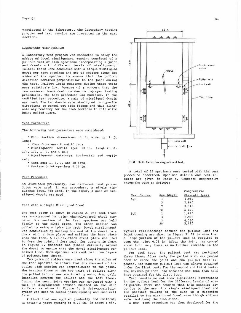
The test setup is shown in Figure 2. The test frame was constructed by using channel-shaped steel members. One section of the test specimen was held firmly to the rigid frame. The other section was pulled by using a hydraulic jack. Dowel misalignment was controlled by welding one end of the dowel to a chair with a base plate and nailing the base plate onto the form. A 1/8-in.-thick steel plate was used to form the joint. A form ready for casting is shown in Figure 3. Concrete was placed carefully around the dowel to ensure that the dowel misalignment remained true. Each specimen was cast over two layers of polyethylene sheets.
Two pairs of rollers were used along the sides of the test specimen to ensure that the movement of the pulled slab section was perpendicular to the joint. The bearing force on the two pairs of rollers along the pulled section was monitored by using load cells installed between the rollers and the test frame. During the test, joint opening was monitored with a pair of displacement sensors mounted on the slab surface, as shown in Figure 4. A data-acquisition system was used to record joint-opening and load-cell data.
Pullout load was applied gradually and uniformly to obtain a joint opening of 0.25 in. in about 1 min.
1· 36 in .,
Load cell
Hydraulic jock
FIGURE 2 Setup for single-dowel test.
Displacement sensor
Roi ler nes1
Load cell
...- rest frame
51
A total of 16 specimens were tested with the test procedure described. Specimen details and test results are given in Table 6. Concrete compressive strengths were as follows:
Compressive Test Series Age (da:ts ) Stren9th (Es i l A,C 1 1,960
3 2,990 7 3,810
28 5,100 B,D 1 1,490
3 2,970 7 4,040
28 5,420
Typical relationships between the pullout load and joint opening are shown in Figure 5. It is seen that a large portion of the pullout load is required to open the joint 0.01 in. After the joint has opened about 0.05 in., there is no further increase in the pullout load.
For each test, the pullout test was performed three times. After each, the pulled slab was pushed back to close the joint and the pullout test repeated. The maximum pullout load was always obtained under the first test. For the second and third tests, the maximum pullout load obtained was less than half that obtained for the first test.
Test results do not show significant differences in the pullout load for the different levels of misalignment. There was concern that this behavior may be due to the use of a single misaligned dowel and the possible pulling of the slab in a direction parallel to the misaligned dowel even though rollers were used along the slab sides.
A new test procedure was then developed for the
52
FIGURE 3 Single-dowel test: form ready for casting.
FIGURE 4 Single-dow~l test: displacement sensors on slab surface.
pullout test. This procedure, using a pair of misaligned dowels, is discussed next.
Test with a Pair of Misaligned Dowels
'l'he test setup for a pair of misaligned dowels is shown in Figure 6. The test frame was the same as that used for the single-dowel tests. However, use of the rollers along the sides of the specimen was discontinued and the specimen length was shortened to 4 ft. For this procedure also, one slab section was held firmly to the test frame while the other slab section was pulled.
For each test, each of the two dowels had the same level of misalignment. However, the dowels were misaligned in opposite directions to cancel out any tendency of the pulled-slab section to tilt horizontally or vertically. Dowel misalignment was controlled by use of chairs. A 1/8-in.-thick steel plate
Transportation Research Record 1062
TABLE 6 Test Details and Results
Maximum Pullout Load (lb) by Test
Test Misalignment Series (in.) 1 Day 3 Days 7 Days 28 Days
A 0 horizontal 1,030 840 1,020 1,640 B 1 /4 horizontal 890 670 980 2,000 c 1 /2 horizontal 1,160 1,270 1,410 1,890 D 1 horizontal 1,460 1,280 1,020 NA
Note: NA= not available. Slab thickness= 8 jn, Maximum joinl opcnini = 0.25 in. Maximurn Aureaate si7f~ = I in.
2000
Pullout Load, 1000
lb
Pullout Load,
lb 1000
005
Fir st pull
0 .10 0 ,15 0 .20
Joint Opening, in.
First pull~ 2000 l
OL....~~-'-~~~~l~~~--'-'~~~~I~~~-'
025
0 005 010 0.15 020 0.25
Joint Open ing 1 in.
FIG URE 5 Relationships between pullout load and joint opening.
36 In.
Hydraulic jock
FIGURE 6 Setup for two-dowel test.
Tayabji
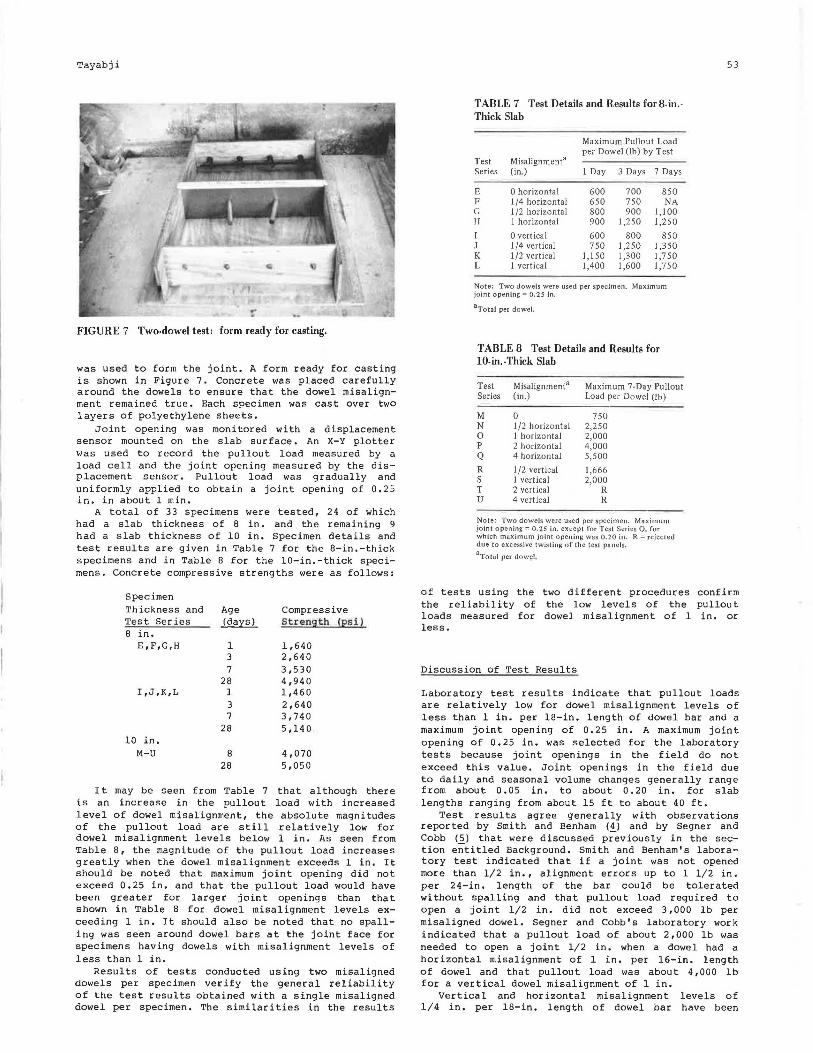
FIGURE 7 Two-dowel test: form ready for casting.
was used to form the joint . A form ready for casting is shown in Figure 7. Concrete was placed carefully around the dowels to ensure that the dowel misalignment remained true. Each specimen was cast over two layers of polyethylene sheets.
Joint opening was monitored with a displacement sensor mounted on the slab surface. An X-Y plotter was used to record th e pullout load measured by a load cell and the joint opening measured by the displacement sensor. Pullout load was gradually and uniformly applied to obtain a joint opening of 0.25 in. in about 1 min.
A total of 33 s pecimens were tested, 24 of which had a sla b thickness of 8 in. and the remaining 9 had a slab thickness of 10 in. Specimen details and test res ults are given in Table 7 for the 8-in.-thick specimens and in Table 8 for the 10-in.-thick specimens. Concrete compressive strengths were as follows:
Specimen Thickness and Age Compressive Test Series ~ Streng th !£Si) 8 in.
E,F,G,H 1 1,640 3 2,640 7 3,530
28 4,940 I,J,K,L l 1,460
3 2,640 7 3,740
28 5,140 10 in.
M-U 8 4,070 28 5,050
It may be seen from Table 7 that al though there is an increase in the pullout load with increased level of dowel misalignment, the absolute magnitudes of the pullout load are still relatively low for dowel misalignment levels below 1 in. As seen from Table 8, the magnitude of the pullout load increases greatly when the dowel misalignment exceeds l in. It should be noted that maximum joint opening did not exceed 0. 25 in. and that the pullout load would have been greater for larger joint openings than that shown in Table 8 for dowel misalignment levels exceeding l in. It should also be noted that no spalling was seen around dowel bars at the joint face for specimens having dowels with misalignment levels of less than l in.
Results of tests conducted using two misaligned dowels per specimen verify the general reliability of the test results obtained with a single misaligned dowel per specimen. The similarities in the results
TABLE 7 Test Details and Results for8-in.· Thick Slab
Maximum Pullout Load per Dowel (lb) by Test
Test Misalignment" Series (in.) 1 Day 3 Days 7 Days
E 0 horizontal 600 700 850 F l /4 horizontal 650 750 NA G l /2 horizontal 800 900 1,100 H l horizontal 900 1,250 1,250 I 0 vertical 600 800 850 J l /4 vertical 750 1,250 1,350 K l /2 vertical 1,150 1,300 1,750 L 1 vertical 1,400 1,600 1,750
Note: Two dowels were used per specimen. Maximum joint opening= 0.25 in.
8 Total per dowel.
TABLE 8 Test Details and Results for 10-in.-Thick Slab
Test Misalignment" Maximum 7-Day Pullout Series (in.) Load per Dowel (lb)
M 0 750 N l /2 horizontal 2,250 0 l hor izontal 2,000 p 2 horizontal 4,000 Q 4 horizontal 5,500
R l /2 vertical 1,666 s l vertical 2,000 T 2 vertical R u 4 vertical R
Note: Two dowels were used per specimen. Maximum joint opening= 0.25 in. except for Test Series Q, for which maximum joint openjng was 0.20 in. R =rejected due to excessive twisting of the test panels.
aTotal per dowel.
53
of tests using the two different procedures confirm the reliability of the low levels of the pullout loads measured for dowel misalignment of 1 in. or less .
Discussion of Test Results
Labor atory test res ults indica te that pullout loads are relatively low for dowel misalignment levels of less than 1 in. per 18-in. length of dowel bar and a maximum joint opening of 0.25 in. A maximum joint opening of 0. 25 in. was selected for the laboratory tests because joint openings in the field do not exceed this value. Joint openings in the field due to daily and seasonal volume changes generally range from about 0.05 in. to about 0.20 in. for slab lengths ranging from about 15 ft to about 40 ft.
Test results agree generally with observations reported by Smith and Benham <!l and by Segner and Cobb (5) that were discussed previously in the section entitled Background. Smith and Benham's laboratory test indicated that if a joint was not opened more than 1/2 in., alignment errors up to 1 1/ 2 in. per 24-in. length of the bar could be tolerated without spalling and that pullout load required to open a joint 1/2 in. did not exceed 3,000 lb per misaligned dowel. Segner and Cobb's laboratory work indicated that a pullout load of about 2,000 lb was needed to open a joint 1/ 2 in . when a dowel had a horizontal misalignment of 1 in. per 16-in . length of dowel and that pullout load was about 4,000 lb for a vertical dowel misalignment of l in.
Vertical and horizontal misalignment levels of 1/ 4 in. per 18-in. length of dowel bar have been
54
considered acceptable in the past by many state hiqhwav aqencies. There was relatively little differenc~ i~ measured pullout loads between specimens incorporating a 1/4-in. misalignment and specimens incorporating a 1/2-in. misalignment.
Because of the limited number of tests that were conducted during the present study and because these tests did not consider the effects of multiple misaligned dowels at a joint, no recommendations are made to change levels of permissible misalignment currently specified by state highway agencies. However, data developed to date from various studies indicate that misalignment levels greater than those currently specified may be acceptable.
To ensure that a realistic specification is developed in the future, it is necessary that a practical, reliable, and cost-effective nondestructive test method be available to measure dowel misalignment in the field. Factors to be considered in developing an effective program of field evaluation of dowel-bar misalignment are given by Tayabji (.!]_).
These factors include consideration of the allowable number of misaligned dowels per Joint and selection of a strategy to resolve the misalignment problem once it is identified.
SUMMARY
An investigation was conducted to develop limits on allowable levels of tolerances for dowel placement at concrete pavement joints. Theoretical analyses of the effect of dowel misalignment were conducted by using finite-element computer programs SAP4 and BMINES. Because of the complexity of modeling slippage between the dowel and the concrete and of simulating the three-dimensional nature of dowel misalignment, the theoretical analysis was not completed.
The effect of dowel misalignment was studied in the laboratory. Test results indicate that pullout loads for dowels with misalignment levels of 1 in. or less are relatively low.
However, no revisions to the currently accepted levels of dowel misalignment are recommended at this time because of the limited amount of laboratory test data and lack of sufficient data on field performance of jointed concrete pavements with misaligned dowels.
It is recommended that a concerted effort be made to document dowel misalignment in the field and to relate the levels of misalignment to performance at the joints. An adequate data base on field performance of jointed concrete pavements incorporating dowels with different levels of misalignment as well as data developed from laboratory tests can then be used to make revisions to the currently used specifications for dowel misalignment.
ACKNOWLEDGMENTS
Work was conducted by the Construction Technology Laboratories under W.G. Corley, Director, Engineering Development, and B.E. Colley, Director, Transportation Development Department. Paul Teng, Richard McComb, and George w. Ring III of the Federal Highway Administration provided technical coordination.
Transportation Research Record 1062
Their cooperation and suggestions are gratefully acknowledged.
REFERENCES
1. Recommended Procedures for Portland Cement Concrete Pavement Joint Design. Transmittal 157. In Federal-Aid Highway Program Manual, FHWA, U.S. Department of Transportation, Sept. 1975.
2. Rigid Pavement Joints. FHWA Technical Advisory T5l40 .lB. FHWA, u .s. Department of Transportation, Dec. 1980.
3. G. Fowler and W. Gulden. Investigation of Location of Dowel Bars Placed by Mechanical Implantation. Report FHWA/RD-82-153. FHWA, U.S. Department of Transportation, May 1983.
4. A.R. Smith and s.w. Benham. Effect of Dowel Bar Misalignment Across Concrete Pavement Joints. Transactions, American Society of Civil Engineers, Vol. 103, 1938.
5. E.P. Segner, Jr., and J.R. Cobb. A Study of Misaligned Dowels in Concrete Pavements. HPR Report 32. Alabama Highway Department, Montgomery, Aug. 1967.
6. B .F. Friberg. Design of Dowels in Transverse Joints of Concrete Pavements. Proc., American Society of Civil Engineers, 1938.
7. J. Weaver and A.J. Clark. The Effect of DowelBar Misalignment in the Joints of Concrete Roads. Technical Report 42.448. Cement and Concrete Association, London, England, Nov. 1970.
8. T.H. Nichols and G.L. Hoffman. Machine Insertion of Plastic-Coated Dowel Bars in PCCP. Research Project 78-8. Materials and Testing Division, Pennsylvania Department of Transportation, Harcisburg, May 1980.
9. M.G. Beeson et al. A Comparative Analysis of Dowel Placement in Portland Cement Concrete Pavements. American Concrete Pavement Association, Arlington Heights, Ill., Dec. 1981.
10. L. Evans. Tolerances of Load Transfer Devices in Portland Cement Concrete Pavements. Tennessee Department of Transportation, Knoxville, April 1981.
11. K.J. Bathe et al. SAP IV--A Structural Analysis Program for Static and Dynamic Response of Linear Systems. Report EERC-73-11. Earthquake Engineering Research Center, University of California, Berkeley, April 1974.
l2 ;- D;E~ Van Dillen et al. Modernization of the BMINES Computer Code, Vol. 1: User's Guide. Bureau of Mines, Denver, Colo., Sept. 1981.
13. S.D. Tayabji. Field Evaluation of Dowel Misalignment in Airfield and Highway Concrete Pavements. Concrete International, Jan. 1986.
The opinions and findings expressed or implied in the paper are those of the author. They are not necessarily those of the Federal Highway Administration.
Publication of this paper sponsored by Committee on Rigid Pavement Construction and Rehabilitation.


![1062 CPP02-CourseIntro.ppt [相容模式]squall.cs.ntou.edu.tw/cpp/1062/slides/1062 CPP02... · Preferred: Knowledge ofprobability theory, stochastic processes, or time series analysis](https://static.documents.pub/doc/80x56/602fb8cc6a16492fd6460712/1062-cpp02-csquallcsntouedutwcpp1062slides1062-cpp02.jpg)


