DOWMCllS177-3307 (DE93000251) Clean Coal Reference Plants: Atmospheric CFB Topical Report Task 1 Lynn N. Rubow Lawrence E. Harvey Thomas L. Buchanan Richard G. Carpenter Matthew R. Hyre Roman Zaharchuk June 1992 Work Performed Under Contract No.: DE-ACZl-89MC25177 For U.S. Department,of Energy Office of Fossil Energy Morgantown Energy technology Center Morgantown, West Virginia BY Gilbert/Commonwealth, Inc. .Engineers and Consultants Reading, Pennsylvania
Transcript
DOWMCllS177-3307 (DE93000251)
Clean Coal Reference Plants: Atmospheric CFB
Topical Report Task 1
Lynn N. Rubow Lawrence E. Harvey Thomas L. Buchanan Richard G. Carpenter Matthew R. Hyre Roman Zaharchuk
June 1992
Work Performed Under Contract No.: DE-ACZl-89MC25177
For U.S. Department,of Energy Office of Fossil Energy Morgantown Energy technology Center Morgantown, West Virginia
BY Gilbert/Commonwealth, Inc. .Engineers and Consultants Reading, Pennsylvania
DISCLAIMER
T16s~wsr~aranaccolmtof~ksponsoredbywagPncyofiheUnitedStatea Oovprtmau. N&ha the hired States Gm anmentmranyagarythereof.manyoftih Fmpbyos.maLa8lywwwry,expesJorimplicdaassumes ~ykgalli&ilitpUCSpS~~~ fMthePmwcy.c.nnpl~GTorusehrlnersofmyinf~ Vi-wW~poass disc- or repsem that iis we would not infxinge privately ovmed righta. Ref- hsfinto any spcsih cmmmial pcdwt press. m smite by ude “em+ fd+zm.zk mmufacans. or omwise cbes mt “eaJsariy cmstiaue (x imply its mdmwnmt d OT fsvring by me united states oovenlmmt m my agary thxof. The views mid o@lions of authns ex- plwed hen do mt lM?&xsdy state or reflect thm of mc united states CbvRnneN or any W-Y-f.
This repat has been repmduced directly from the best available copy.
Available lo DOE and DOE contractors from Ihe Office of Scientific and Technical Information. P.O. Box 62, Oak Ridge. TN 37831; prices available from (615) 5764401.
Available to the public from the National Technical Information Service. U.S. Department of Commerce, 5285 Port Royal Rd., Spingtield. VA 22161, (703) 4874650.
D04MC/Z5177-3307 (DE93000251)
Distribution Categcay UC-103
Clean Coal Reference Plants: Atmospheric CFB
Topical Report Task 1
Lynn N. Rubow Lawrence E. Harvey Thomas L. Buchanan Richard G. Carpenter
Matthew R. Hyre Roman Zaharchuk
Work Performed Under Contract No.: DE-AC21-89MC25177
For U.S. Department of Energy
Office of Fossil Energy Morgantown Ener
P.O. KDX 880 Technology Center
Morgantown, West Virginia 26507.OSLO
BY BY Gilbert/Commonwealth, Inc. Gilbert/Commonwealth, Inc. Engineers and Consultants Engineers and Consultants
The Clean Coal Technology Demonstration Program is a government and industry cofunded technology development effort to demonstrate a new generation of innovative coal utilization processes in a series of full-scale facilities. The goal of the program is to provide the U.S. energy marketplace with a number of advanced, more efficient and environmentally responsive coal-using technologies.
The Morgantown Energy Technology Center (METC) has the responsibility for monitoring the CCT Projects within certain technology categories, which correspond to the center’s areas of technology development, including atmospheric fluidized bed combustion, pressurized fluidized bed combustion, integrated gasification combined cycle, mild gasification, and industrial applications.
A measure of success in the CCT program will be the commercial acceptance of the new technologies being demonstrated. The dissemination of project information to potential users is being accomplished by producing a series of reference plant designs which will provide the users a basis for the selection of technologies applicable to their future energy requirements.
As a part of DOE’s monitoring and evaluation of the CCT Projects, Gilbert/Commonwealth (G/C) has been contracted to assist in this effort by producing the design of a commercial size Reference Plant, utihzing technologies developed in the CCT Program. This report, the fust in a series, describes the design of a 400 MW electric power plant, utilising an atmospheric pressure, circulating fluidized bed combustor (ACFB) similar to the one which was demonstrated at Colorado-Ute’s Nucla station, funded in Round 1 of the CCT Program. The Nucla plant was used as the basis for the 400 MWe Reference Plant design.
The Nucla project involved the installation of a 110 MWe Pyropower ACFB which was, at that time, the largest of its kind in the world. The boiler replaced three existing coal tied units which were retired. The size of the boiler was such that it provided the last critical link between small test facilities and a commercial size plant.
The plant operated for four years under Electric Power Research Institute (EPRI), Department of Energy (DOE) and Colorado-Ute sponsorship, providing operational and design data for scale-up purposes. Data showed that nearly all performance guarantees were,met. Although typical startup and maintenance problems were experienced, they were not related to deficiencies in the ACFB technology and were not considered significant.
Combustion and boiler efficiencies were as expected and SO2 and N4, emissions were below permit levels. Databases were initiated for material-related problems and for reliability of equipment components. Three coals were tested. Section 2 provides a description of the Nucla facility, and a brief summary of operating experience.
The intent of the reference plant design effort was to portray a commercial power plant with attributes considered important to the utility industry. The logical choice for the ACFB combustor was Pyropower since they supplied the ACFB for the Nucla Project. The design used for the Reference Plant, however, is different in several significant areas such as the use of reheat, double
E-l
loop seals, internal wingwalls, pigtail nozzles, etc. The reasons for the changes are discussed in the portion of Section 3 describing the combustor.
The nominal size of the Reference Plant is 400 MWe, which is comprised of one 400 MWe turbine generator and two 200 MWe combustors. The 200 MWe combustor size was selected based on projections of future availabilities of commercial guarantees; satisfactory predicted operating availabilities; the current and projected need for units in the 400 MWe range; and the reasonableness of the size extension of similar units that are presently operating. Some ACFB plants currently in the planning process are larger (2.50 to 300 MWe) than the combustors proposed for this plant. However, for the purposes of this effort, it was felt that the Reference Plant should represent a commercial plant that would be built in the relatively near future with the expectation of high availability, based on significant operation of a similar size plant.
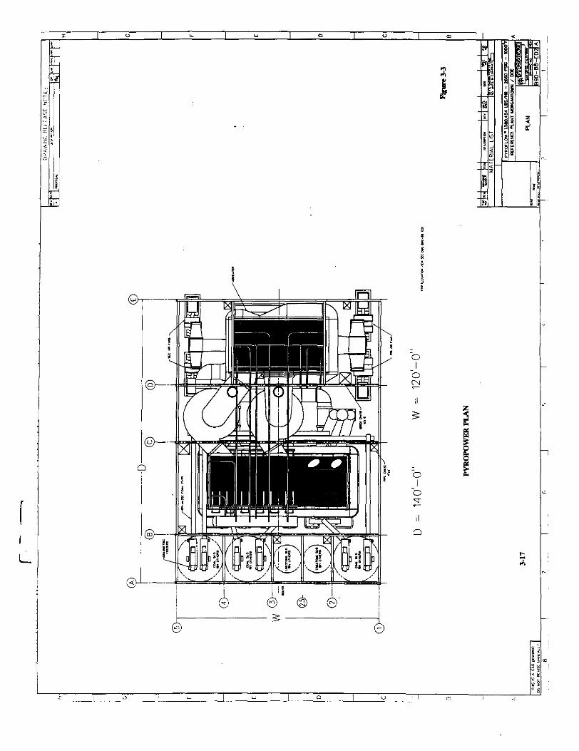
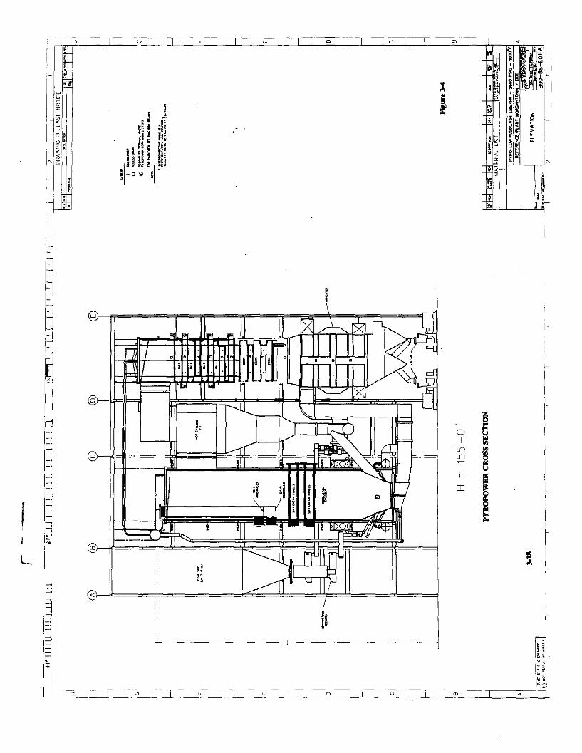
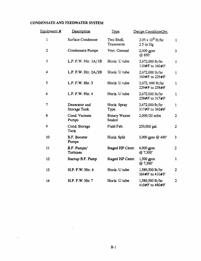
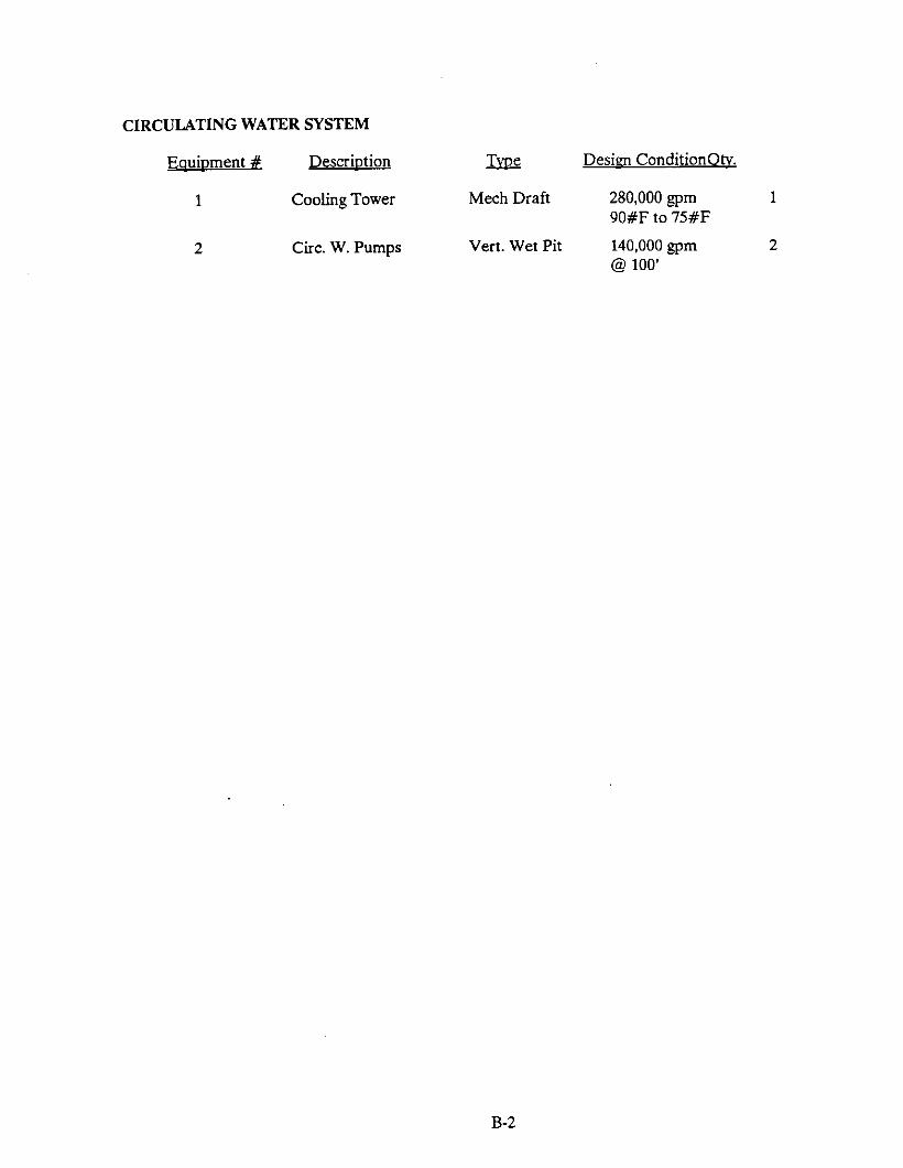
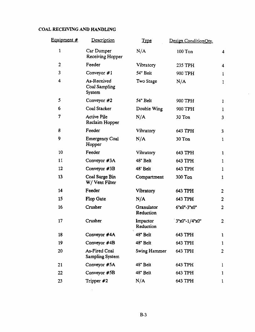
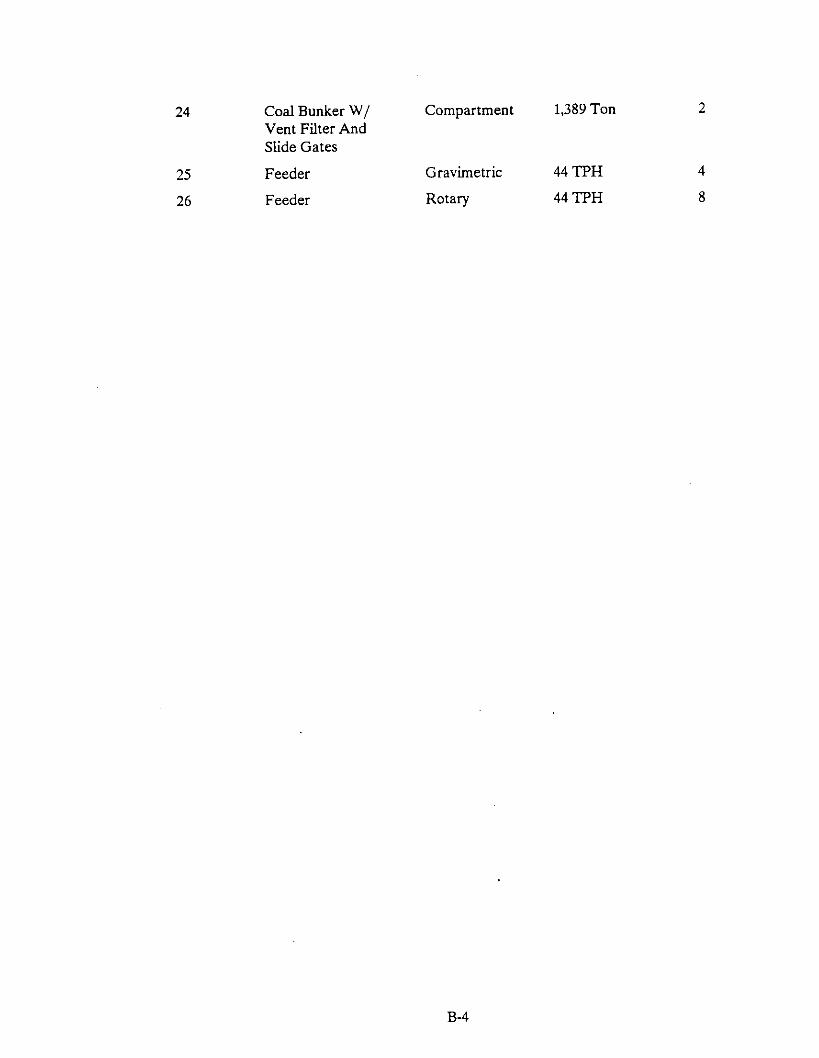
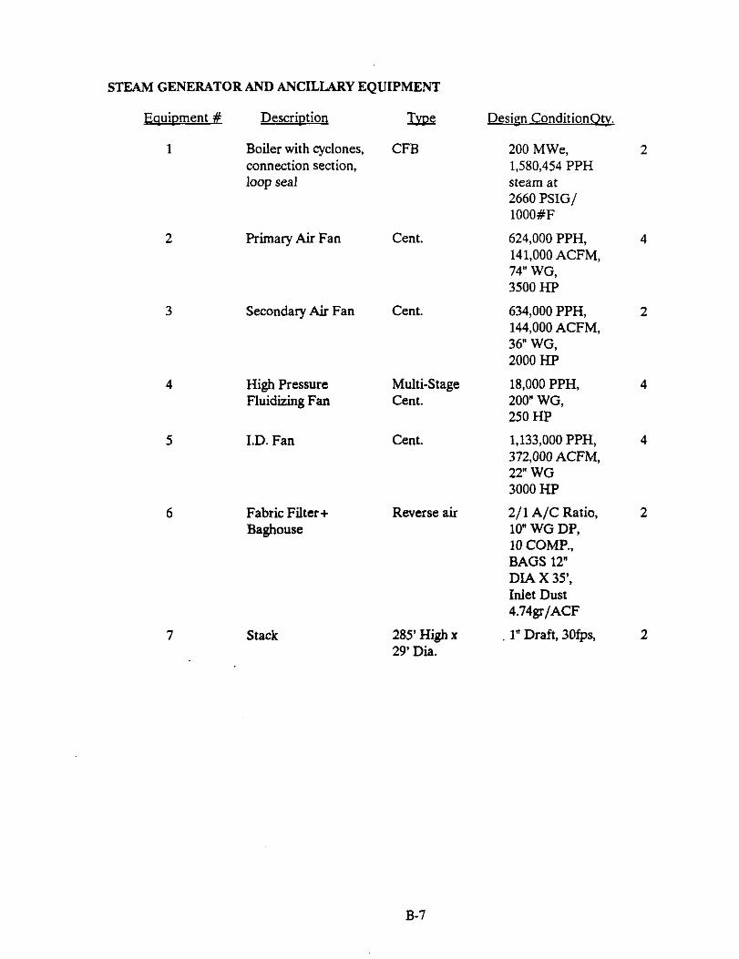
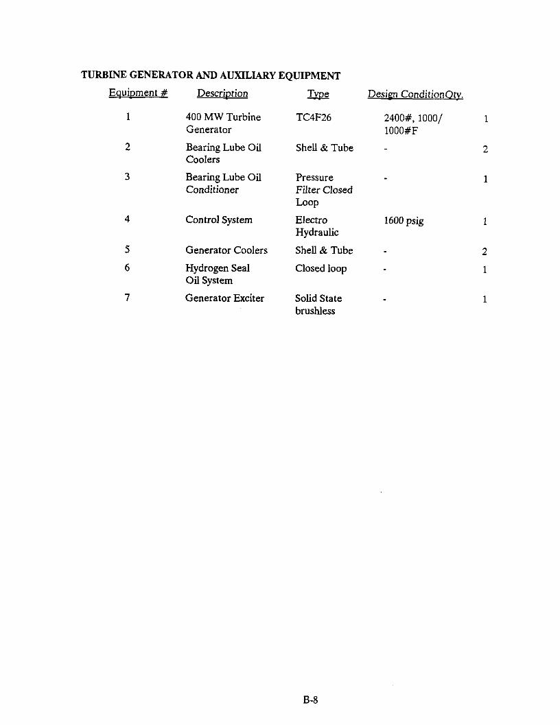
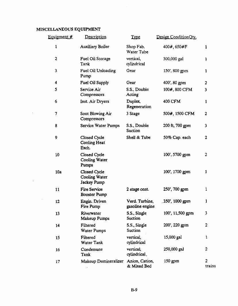
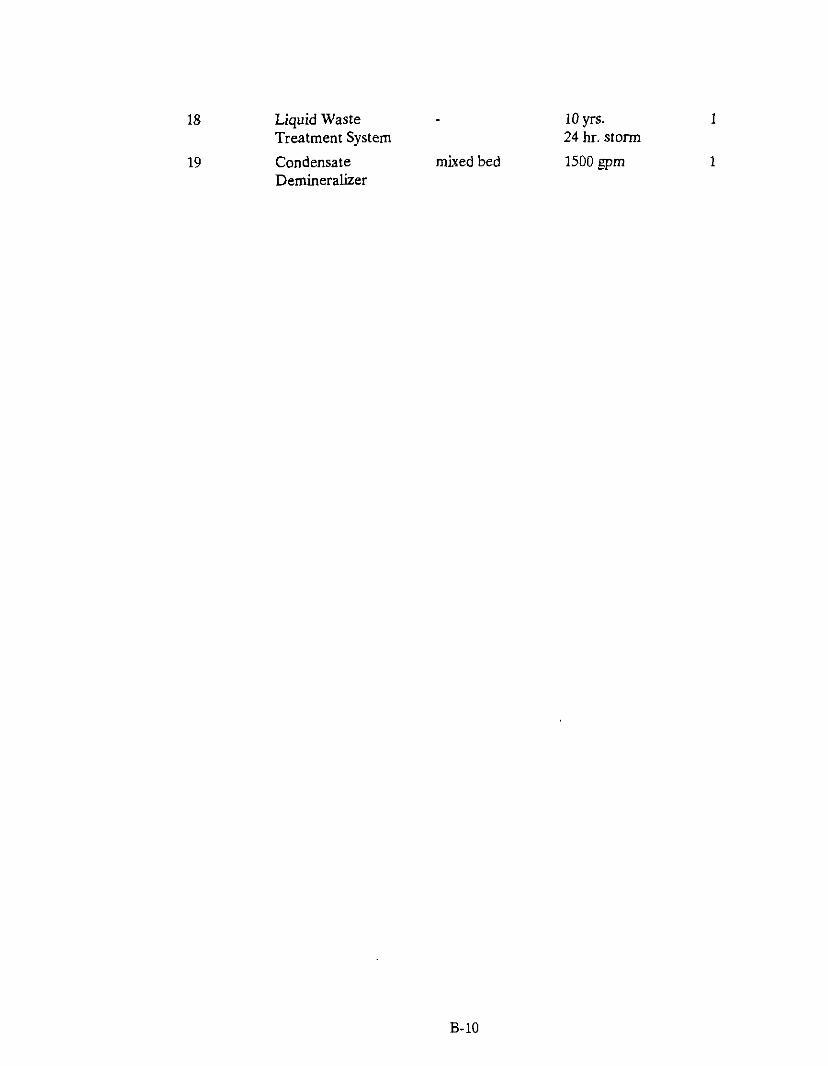
Section 3 provides a detailed description of the Reference Plant. Heat balances are shown as well as system diagrams for the major systems and plant layouts showing equipment arrangements. An equipment list is contained in the Appendix B.
To provide uniformity in comparisons of Clean Coal Technologies, a consistent design basis was applied, including the following factors:
.
.
.
.
.
.
.
l
.
.
.
.
.
.
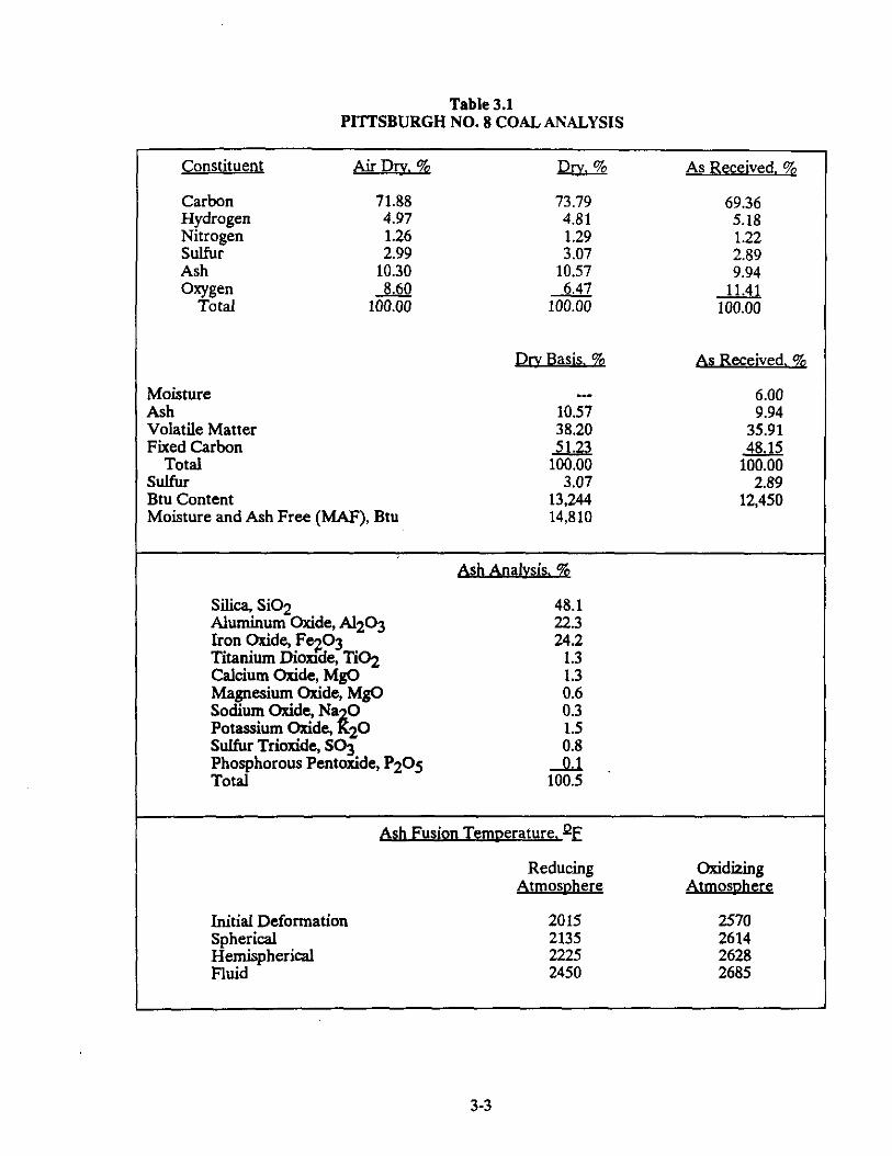
Plant Site and Ambient Design Conditions
Fuel and Sorbent Characteristics
Plant Capacity and Design Life
Plant Availability, Approach to Redundancy
Maturity of Plant Technology, n* Plant
Design Steam Conditions
Approach to Insulation and Lagging
Preheating/Start-up Requirements
Modes of Operation, Turndown, Minimum Load
Control System Design Approach
Plant Services Requirements
Structures and Foundations, Soil Bearing Loads
Heat Recovery Approach
Applicable Codes and Standards
E-2
Reference Plant Desim
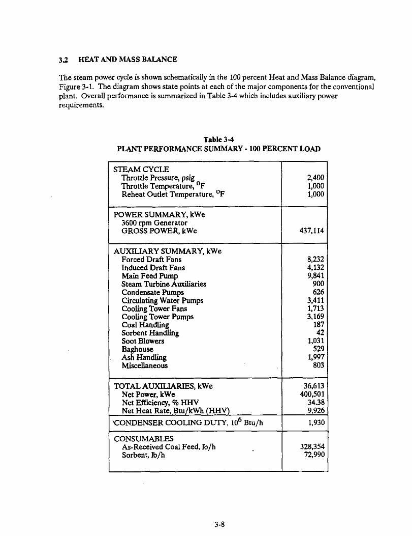
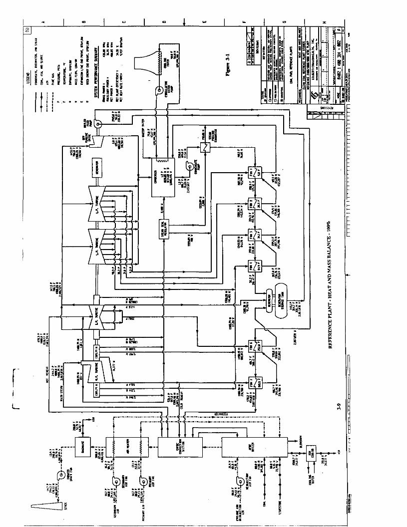
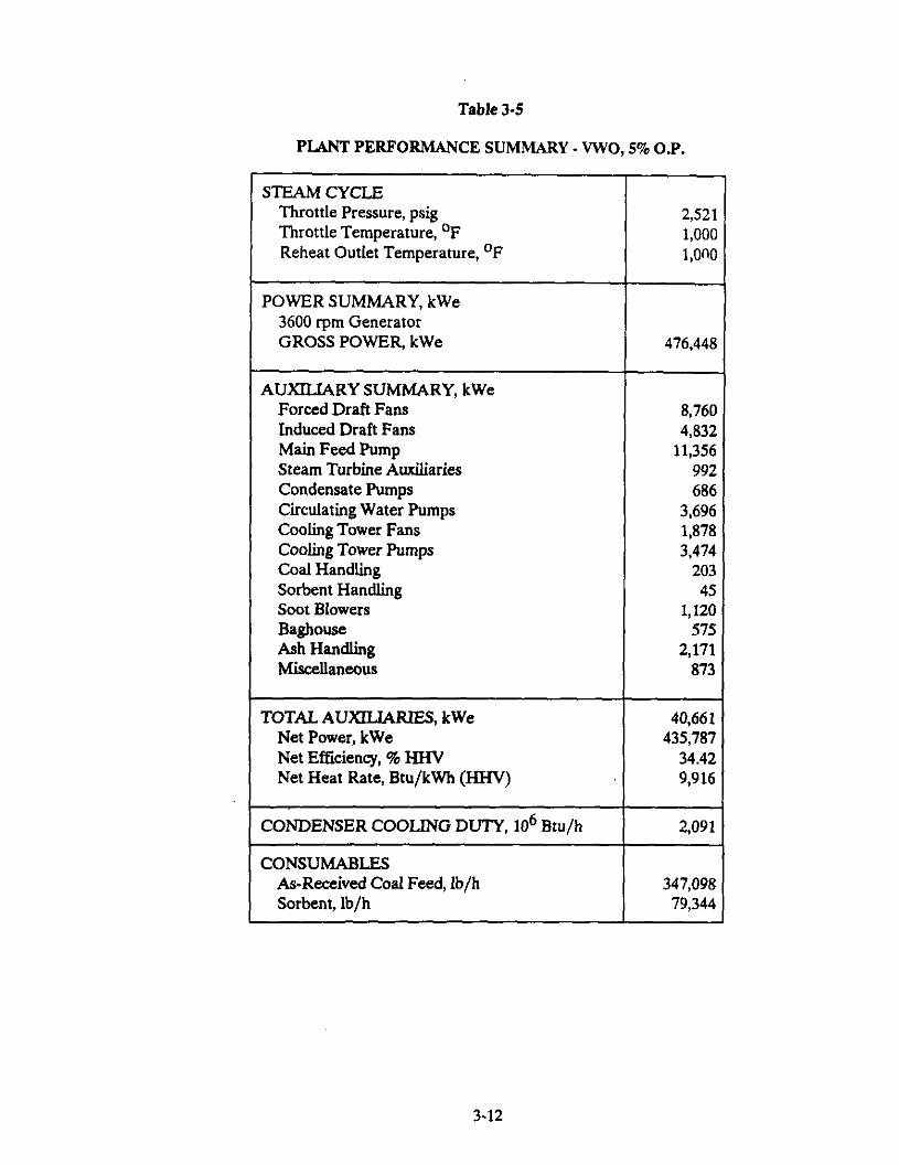
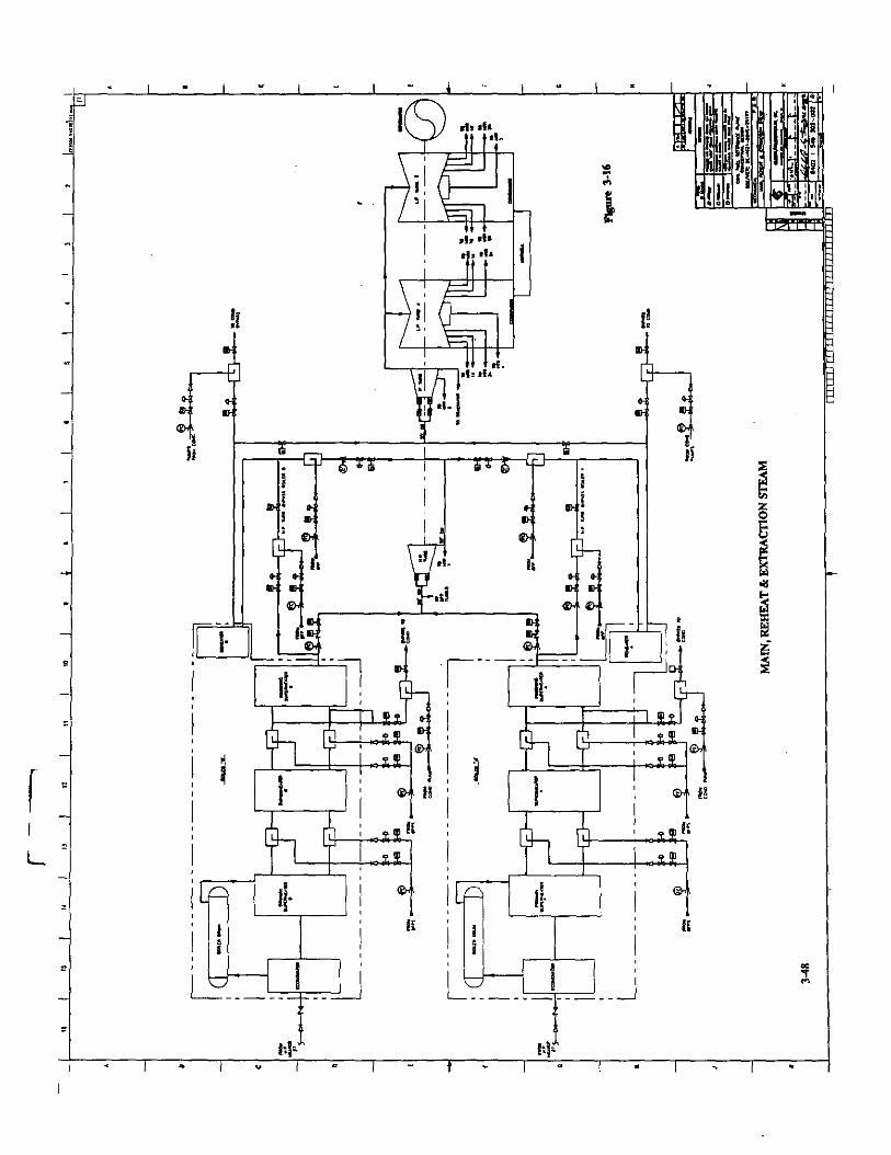
The Reference Plant uses a 2400 psig/lOOO°F/lOOOOF single reheat steam power cycle. The high pressure turbine uses 2867,038 lb/h steam at 2415 psia and 1000’F. The cold reheat flow is 2,603,391 lb/h of steam at 531 psia and 617’F, which is reheated to 1OOO’F before entering the intermediate pressure turbine section. The net plant output power, after plant auxiliary power requirements are deducted, is 400 MWe. The overall net plant (HHV) efficiency is 34.35 percent.
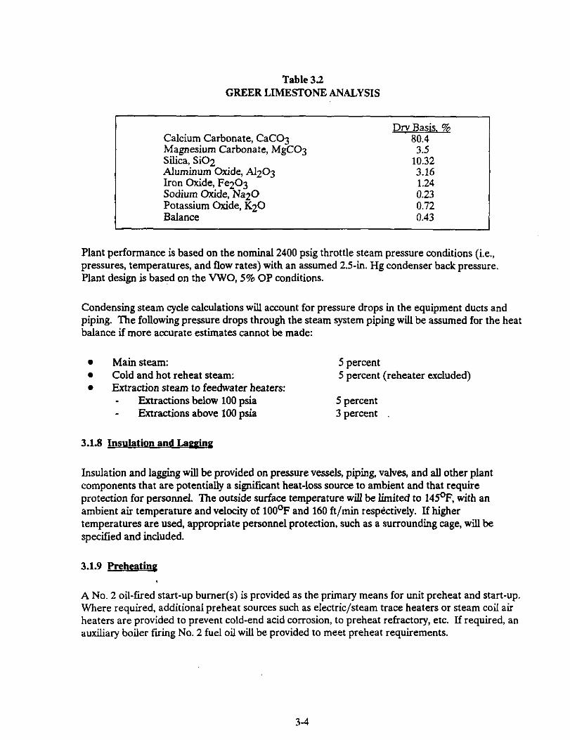
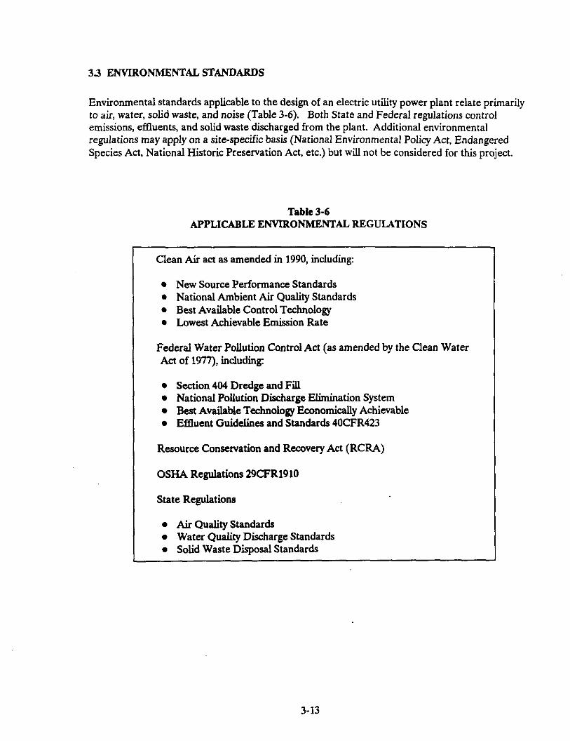
The Reference Plant is expected to meet all applicable Federal, State, and Local environmental standards relating to air, water, solid waste and noise. A calcium-in-the-limestone to sulfur-in-the-coal ratio of 2.5 to 1 ensures an SO2 emission rate of less than 0.371 lb/lo6 Btu (92% reduction). Air quality regulations concerning other compounds such as CO, CO2 and air toxics now being considered may have an effect on the design of plants in the time frame being considered here. However, details of the end results of these considerations are not clear at the present time and are not included in this report.
Because of the increasing international concern about the greenhouse effect, the discharge of N20 from combustion sources has gained recent attention. Fluid&red beds are known to emit larger amounts of N20 than PC boilers per unit size, primarily because of the lower combustion temperature. Reduction of N20 can be accomplished in several ways, all of which have offsetting drawbacks or penalties. The control or reduction of N20 has not been addressed in this design because N20 levels are presently unregulated.
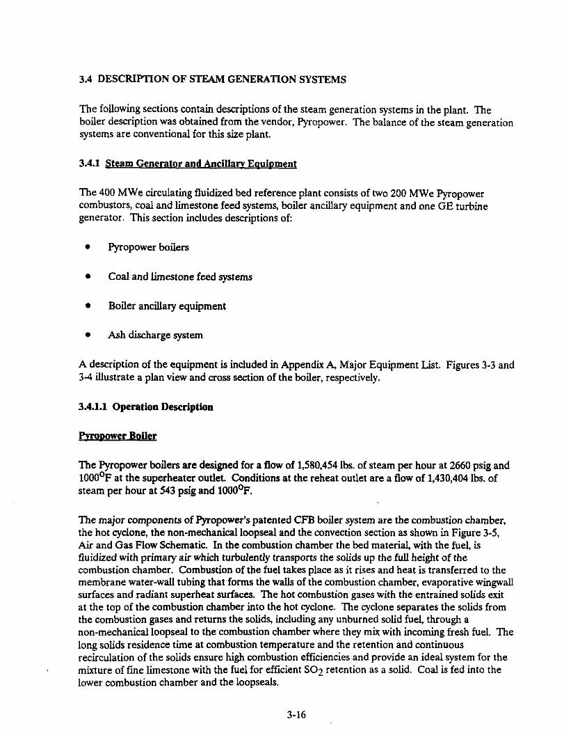
Each boiler is designed for a flow of 1580,454 lbs. of steam per hour at 2660 psig and 1OOO’F at the superheater outlet. Flow at the reheat outlet is 1,430,404 Ibs. of steam per hour at 543 psig and 1000’F.
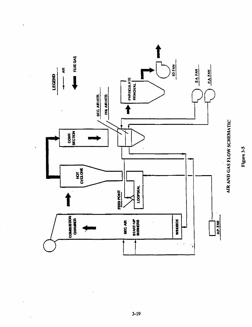
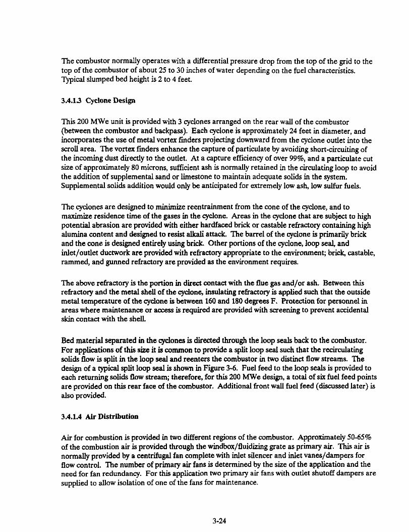
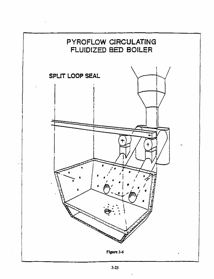
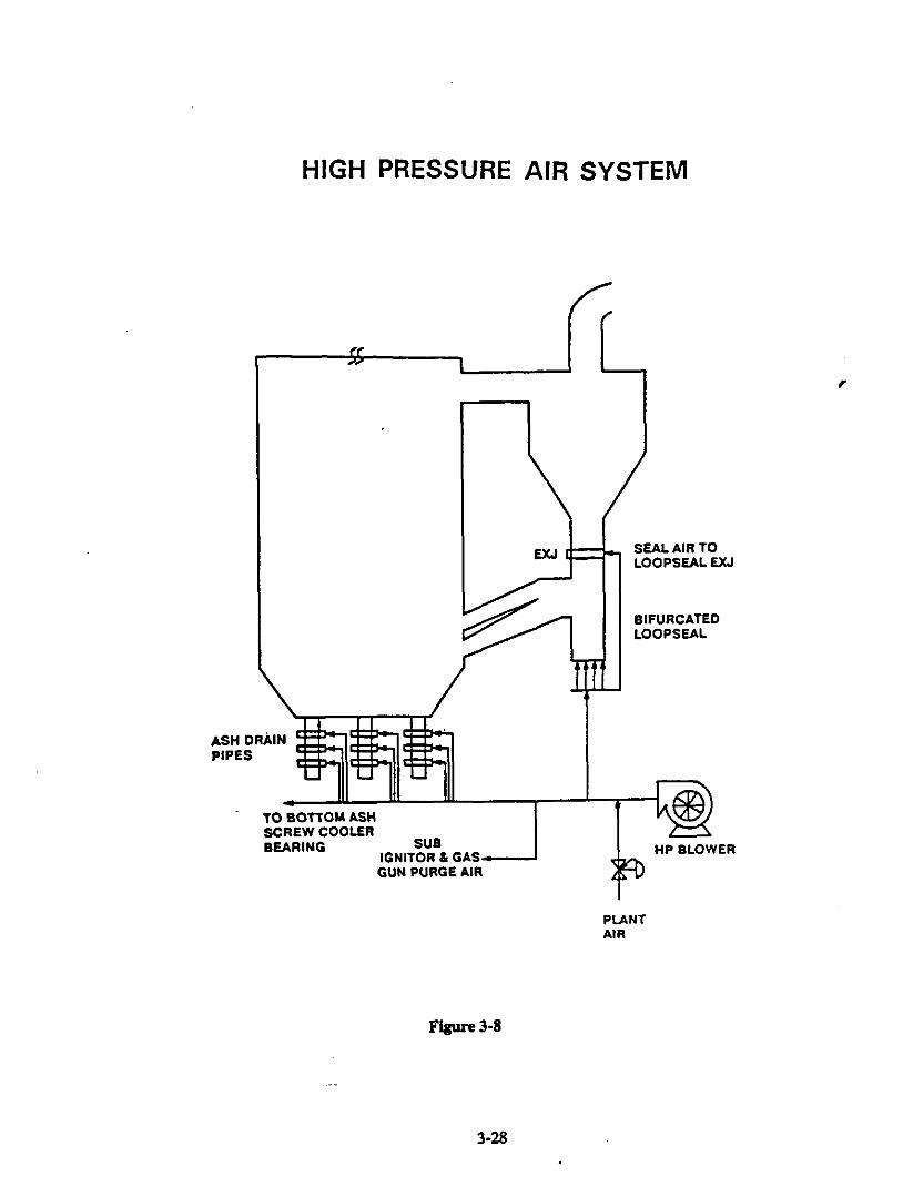
The major components of the boiler system are the combustion chamber, the hot cyclone, the non-mechanical loopseal and the convection section. In the combustion chamber the bed material, with the fuel, is fluidized with primary air. Heat is transferred to the membrane water-wall tubing that forms the walls of the combustion chamber, evaporative wingwall surfaces and radiant superheat surfaces. The hot combustion gases with the entrained solids exit at the top of the combustion chamber into the hot cyclone. The cyclone separates the solids from the combustion gases and returns the solids, including any unburned solid fuel, through a non-mechanical loopseal to the combustion chamber where they mix with incoming fresh fuel. The long solids residence time at combustion temperature and the retention and continuous recirculation of the solids ensure high combustion efficiencies and sulfur capture. Coal is fed into the lower combustion chamber and the loopseals.
The lower section of the combustion chamber includes a water cooled air distribution grid and a bottom ash removal system. Primary air is supplied through the lower windbox to the distribution grid providing fluidization air flow. Secondary air entering above the bed ensures solids circulation, provides staged combustion for NOx reduction and supplies air for continuous fines combustion in the upper part of the combustion chamber.
Flue gas and some particulate matter leave the hot cyclone collector and pass through the convection section which contains primary and final superheat, reheat and economizer banks, plus
E-3
a tubular air preheater. The flue gas then enters a reverse air baghouse where particulate matter is removed in compliance with environmental regulations. Clean flue gas is discharged to the stack via the induced-draft fan. The economizer is a bare tube, in line, horizontal serpentine type heat exchanger, arranged in multiple banks. The air heater is tubular, designed with gas over the tubes and air through the tubes.
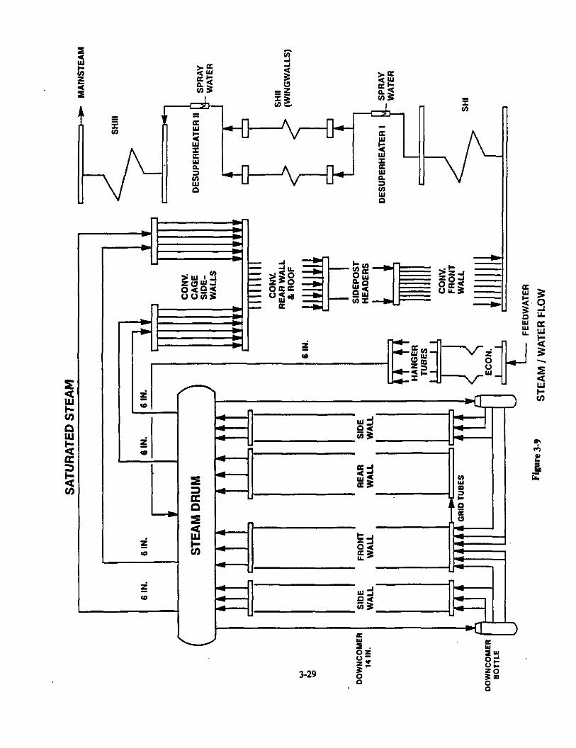
Feedwater enters the economizer and counterflows against the flue gas, picking up heat before entering the drum. Water flows from the drum to the lower combustion chamber headers via downcomers and supply pipes. The combustion chamber is designed for complete natural circulation.
Dry, saturated steam from the drum is delivered to the convection cage walls, and then to the superheater. Heat from the flue gases is transferred to the superheated steam in multiple stages (primary and final) with attemperation between each stage. Main steam exits the outlet header of each boiler’s final superheater, is headered, and delivered to the turbine generator.
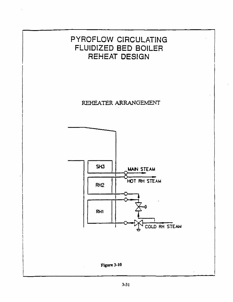
Cold reheat steam from the high pressure turbine is split and directed to the reheat inlet header. Hot reheat steam flow from the reheater is also headered and sent to the intermediate pressure turbine.
The design used for the Reference Plant is improved from that used for Colorado Ute’s Nucla Plant in several significant areas. The following partial list includes the more important changes and their basis. In general, changes have been made to improve reliability where operation has shown the need for modification, or to address performance in terms of carbon bumup efficiency, NOx production, or limestone calcium utihzation.
Double loop seals will be used to allow recirculating solids to re-enter the combustor in two distinct flow streams for better distribution.
16 vs. 8 limestone feed points to improve contact with SO2.
An in-combustor omega superheat surface is designed to provide a flat surface parallel to the upward flowing gas in the combustor, thus minimixing erosion.
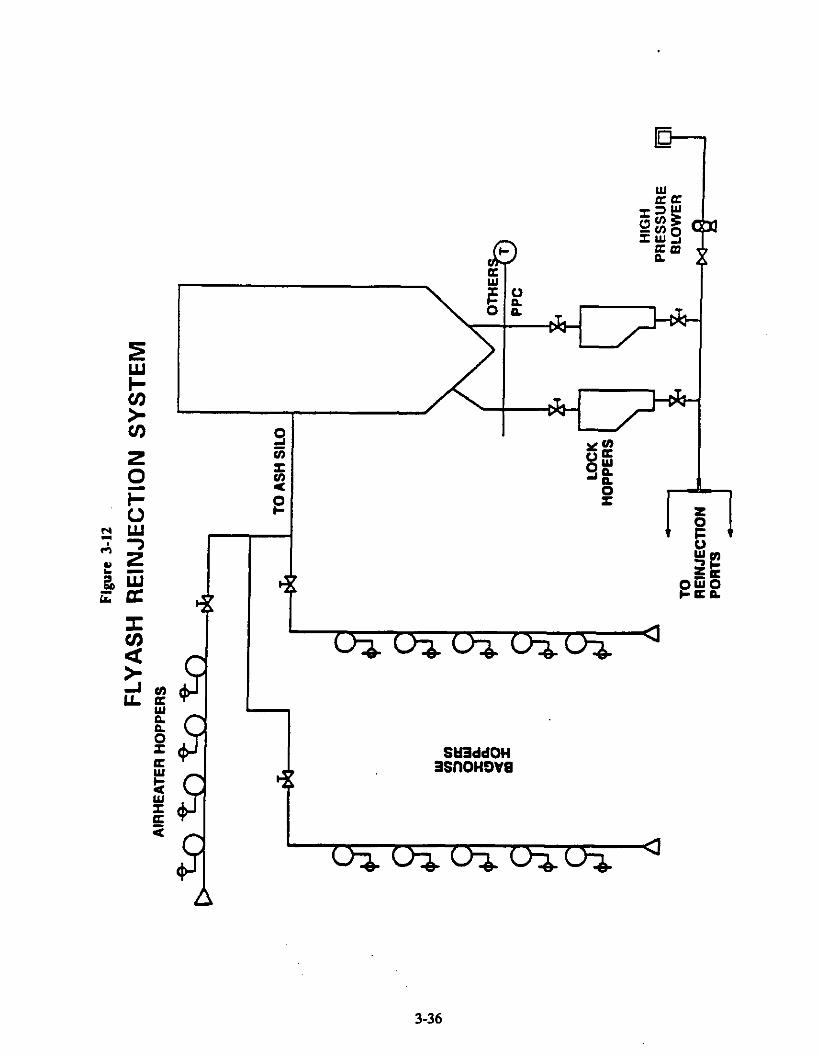
A flyash reinjection system was added to optimize limestone utilization and carbon burnout.
Refractory brick is used instead of castable or gunnite to minimixe erosion.
A cyclone configuration change to lessen reentrainment and maximize gas residence time in the cyclone has been made.
A single piece vortex finder was added to the cyclone to prevent shortcutting and enhance particulate capture.
The refractory interface design was changed to eliminate ash eddying and decrease erosion potential.
E-4
. Pigtail nozzles are used instead of bubblecaps to reduce backsifting of ash into the windbox.
. A change in the air supply source was made to allow initial variation in the primary/secondary air split to provide optimum heat transfer, performance, and emission characteristics for the combustor system.
. A single combustion chamber was designed instead of two.
. The rotary feed valve/pressurisation of the feed system was eliminated.
. The ‘krap-around” combustor superheat surface was eliminated and the bachpass superheat hanger design was changed.
It is expected that the combustor design wih continue to change as more operating experience is obtained, and that improved performance, reliability, and cost-competitiveness wiII be the result.
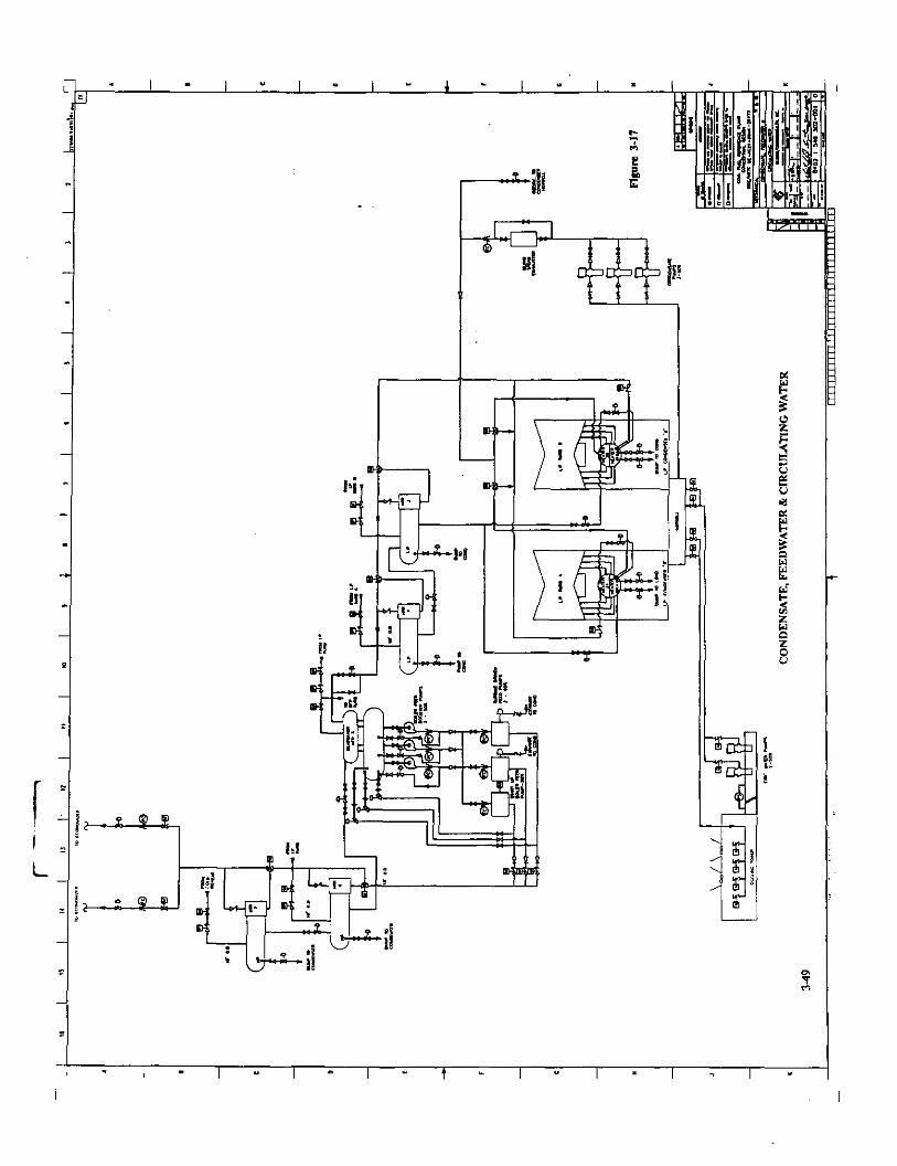
The balance of plant is similar to coventional PC based electric utility power plants. A seven stage regenerative feedwater heating design is used, with a deaerating feedwater heater as the 5th stage. Condenser circulating water is cooled by a mechanical draft cooling tower.
jkonomic Antztvs~
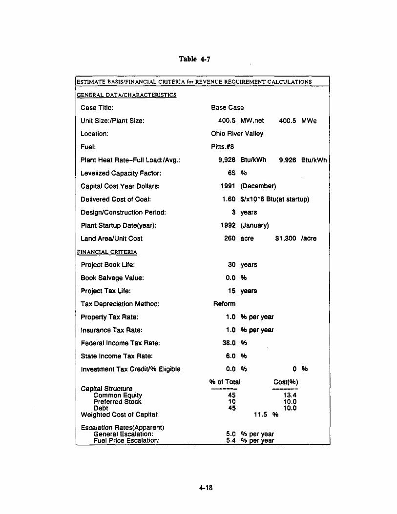
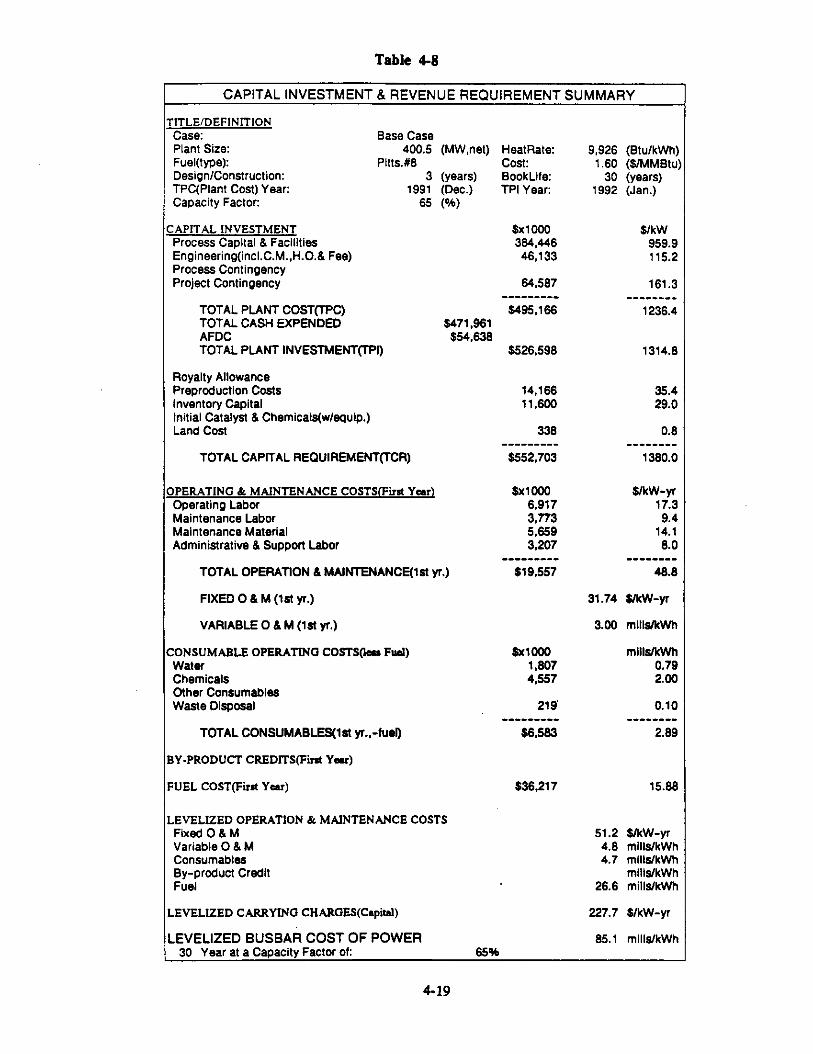
Following the design of the Reference Plant, an economic analysis was performed to provide capital and O&M costs. Section 4.0 contains this analysis and Appendix C has second level cost details. A brief summary of the costs is given below:
1,380
2.89 15.88
Total Capital Requirement Fixed O&M (1st year) Variable O&M (1st year) Total consumables (1st year) Fuel cost (1st year) Levelized Busbar Cost of Power
6,583 36,217
31.82 S/kw-yr 3.01 mills/kwh
87.9 rnills/kwh
Conclusions
The Nucla Project has produced data which has confirmed the predicted performance and provided a basis for the design of future commercial ACFB based power plants. The Reference Plant illustrates one commercial design that could be built based on that experience.
It is apparent that CFB boilers are an established option for utilities considering the addition of capacity to their system, or in retrofitting existing capacity. Continued operation and improved reliability will serve to increase utility confidence in the technology.
It is recommended that the progress of CFB technology be monitored closely and that this Reference Plant design be updated as major advances occur. Parallel efforts of FBC development
E-5
are also ongoing with different versions of AFB technology. The applicability of the various designs with regard to load change, minimum load, emissions mitigation potential, combustor maximum size limitations, efficiency, and reliability should be evaluated, since each design has unique advantages. These developments should also be monitored, and comparisons made of commercial reference plant designs which are based on similar design criteria.
E-6
1.0 INTRODUCTION
The Clean Coal Technology Demonstration Program (CCT) is a government and industry cofunded technology development effort to demonstrate a new generation of innovative coal utihzation processes in a series of full-scale facilities. The goal of the program is to provide the U.S. energy marketplace with a number of advanced, more efficient, and environmentally responsive coal-using technologies. To achieve this goal, a multiphased effort consisting of five separate solicitations is underway. At this time, four solicitations have been completed and the fifth solicitation is planned for 1992.
The Morgantown Energy Technology Center (METC) has the responsibility for monitoring the CCT Projects within certain technology categories, which, in general, correspond to the center’s areas of technology development. Primarily the categories of METC CCT projects are: atmospheric fluid bed combustion, pressurized fluidized bed combustion, integrated gasification combined cycle, mild gasification, and industrial applications.
A measure of success in the CCT Program will be the commercial acceptance of the new technologies being demonstrated. In order to achieve this commercial acceptance it is necessary to provide the potential technology users with project information in a format which allows the technology users to translate the results from the demonstration project to their particular circumstances.
DOE is monitoring project performance and evaluating project operating results. Based on this data, technology vendor input, and in-house expertise, Gilbert/Commonwealth, Inc., was contracted by DOE/MBTC to assist in this effort, and has developed a 400 MWe ACFB Reference Plant design which will be comparable with other reference plants. One objective of this work is to produce a series of reference plant designs which will enable the end user to select the technologies to be applied to meet future energy requirements.
This report describes the results of the effort to design a mature, commercial power plant utilizing a technology demonstrated under the CCT program. This first report in this series is based on the atmospheric-pressure, circulating, fluidized-bed combustor (ACPB) which was demonstrated at Colorado Ute’s Nucia Station. The plant design and cost estimate provided are of sufficient detail to allow potential technology users to adjust the results to their specific conditions.
l-l
2.0 SUMMARYOFBASELINEPLANTANDSCALE-UPPHILOSOPHY
The objective of the study is to produce a conceptual design of a commercial power plant utilising the technology being developed as part of the Clean Coal Program. The basis, or Baseline Plant, of the commercial size Reference Plant described in this report is the Nucla Project, a circulating atmospheric pressure fluid bed plant funded in Round 1 of the DOE Clean Coal Technology Program. The plant described is the Nucla Plant as modified by the installation of the atmospheric fluidized bed boiler. A description of this project and the methods used to develop the basis for the Reference Plant are contained in this Section.
2.1 BASELINEPLANTDESIGN
In 1982 Colorado-Ute Electric Association (CUEA) evaluated options for upgrading the Nucla Station facility. The plant had three 12.6 MWe, stoker fired units burning local bituminous coal and was burdened with low efficiency and high operating costs.
After two years of study, a decision was made to retire the three existing boilers and install a 110 MWe circulating fluidized bed boiler. At the time of construction in 1985 this boiler was the largest of its type in the world. The Electric Power Research Institute (EPRI) assisted in preparing boiler specifications and agreed to participate in the project. In 1984 the National Rural Utilities Cooperative Finance Corporation approved a project loan of $87 million and the Rural Electrification Administration approved the project.
In 1984, Pyropower was awarded the boiler contract. Subsequently, tests of Nucla coal and local limestone were conducted in a small scale AFBC plant to provide data for boiler design. In the spring of 1985 construction started and two years later the first coal fig began.
In October of 1987 the ongoing CUEA project was selected in the first round of the DOE Clean Coal Technology (CCT) Demonstration Program. Under the cooperative agreement between CUEA and the DOE, DOE participated in Phase 3: Operation. Over 4400 hours of operation were logged using low sulfur Colorado coals during acceptance tests which were completed in October, 1988. Performance testing began in March, 1989 and continued through March, 1991, during which high ash and high sulfur coals were tested.
The project completed the scheduled testing program in March, 1991, after operating 15,707 hours. The size of the unit is such that it provided the last critical link between small test facilities and commercial size plants.
Data from 72 tests performed on the unit showed that both SO2 and Nq emissions were below the permit level limits of 0.4 and 0.5 lb/lo6 Btu respectively. Combustion efficiency ranged from 96.9% to 98.9% and boiler efficiency varied between 85.6% and 88.6%. Three coals were tested. No significant operating problems were experienced but a ten week outage occurred due to the structural damage to waterwalls when one combustion chamber overheated. Few materials-related problems were encountered during the four years of operation and a reliability monitoring database was initiated to provide data on frequency of failure for equipment components.
2-1
2.1.1 Overall Plant Design
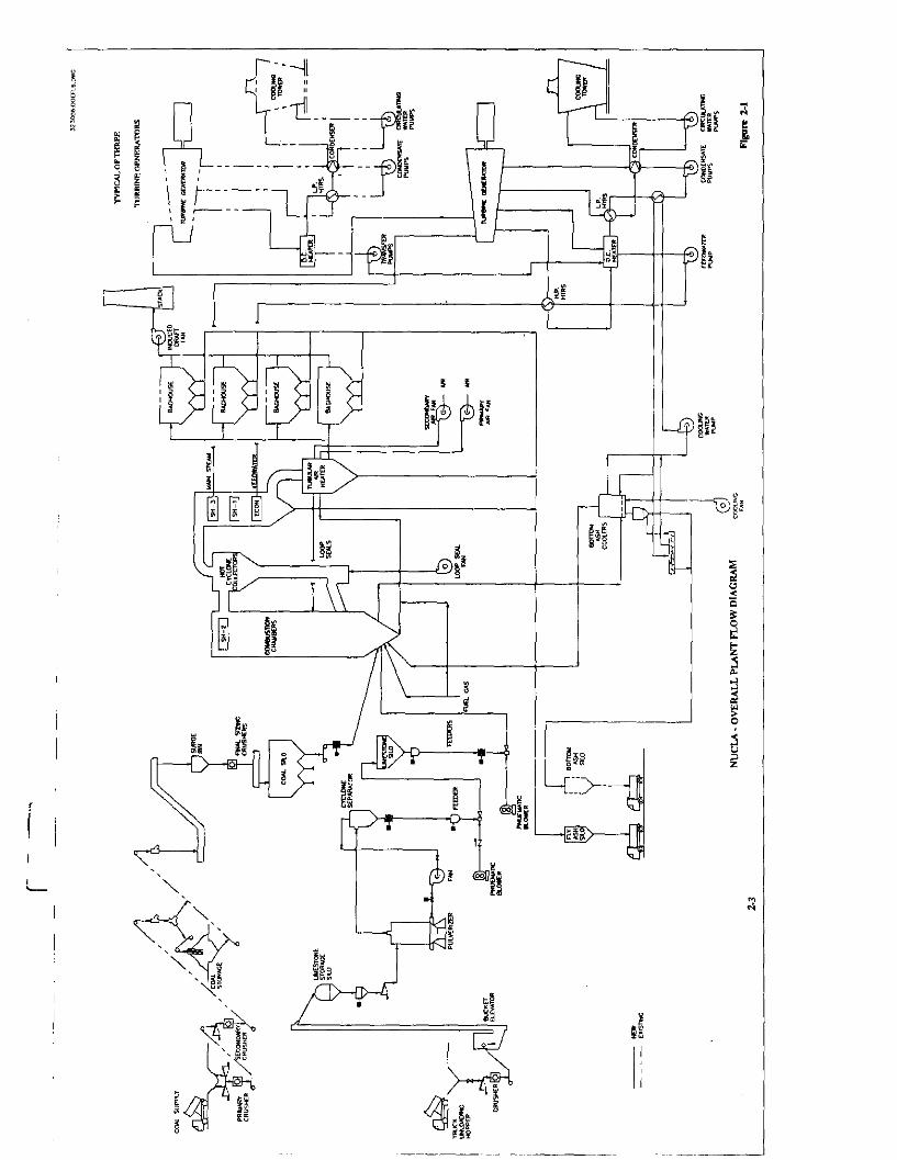
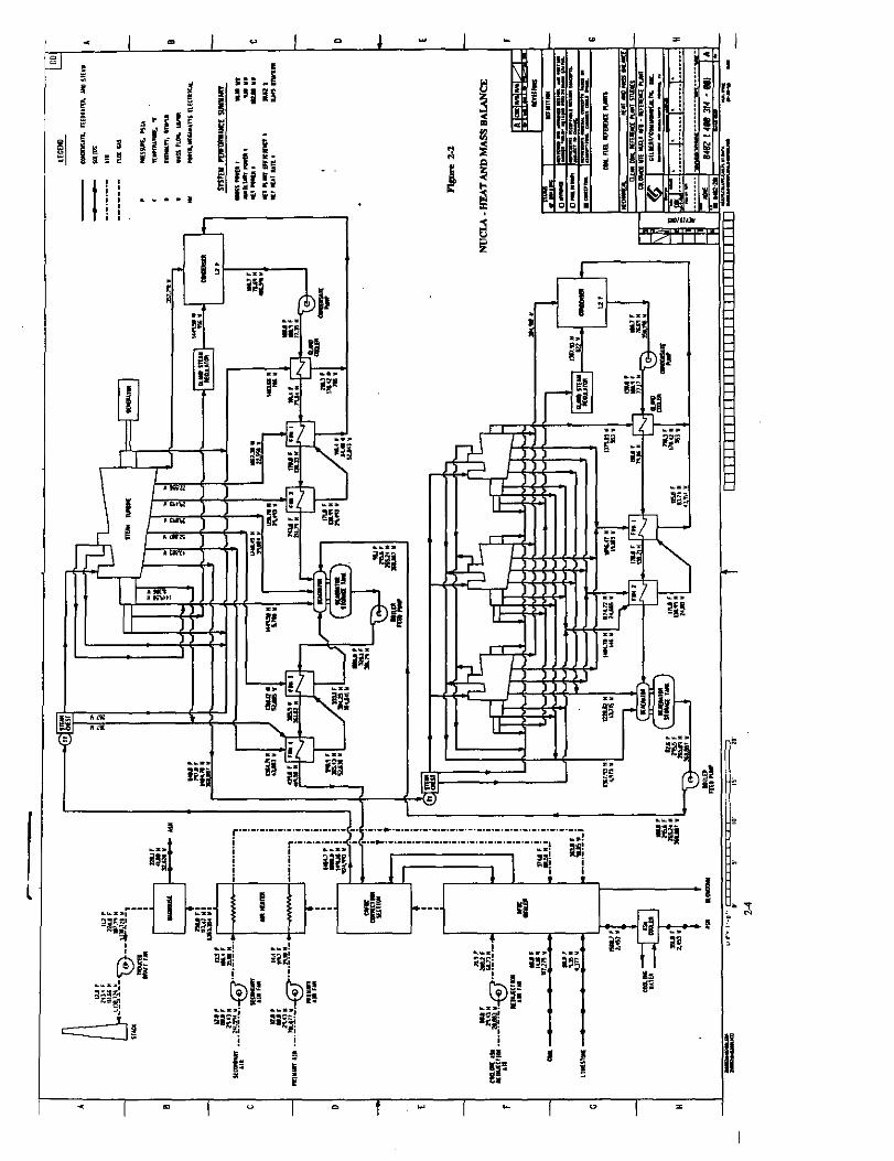
Prior to installation of the circulating fluidized bed boiler, the Nucia plant consisted of three identical stoker boiler units, each rated at 12.6 MWe. Each boiler supplied a turbine generator at inlet conditions of 600 psig and 825’F. The existing units were all commissioned in 19.59. The ACFB addition was designed to integrate the existing plant equipment into the new plant cycle. However, to improve heat rate it was decided to elevate the steam conditions. After analysis of several options, the plant was designed for throttle steam conditions of 1450 psig and 1000°F. The retrofit design incorporated the addition of a new 74 MWe steam turbine for a total plant output rating of 110 MWe. Exhaust steam from this turbine supplies steam to the three existing 12 MWe turbines. The existing stoker boilers were retired. A flow diagraq for the overall plant is shown in Figure 2-1. An overall heat and mass balance is given in Figure 2-2.
2.12 Description of Maior Svstems
The following sections contain descriptions of the major systems in the plant, with most detail concentrated on the systems and equipment affected by the modifications made in the ACFB conversion.
2.1.2.1 Steam Generator and Ancillary Equipment
Pvrcmower Boiler
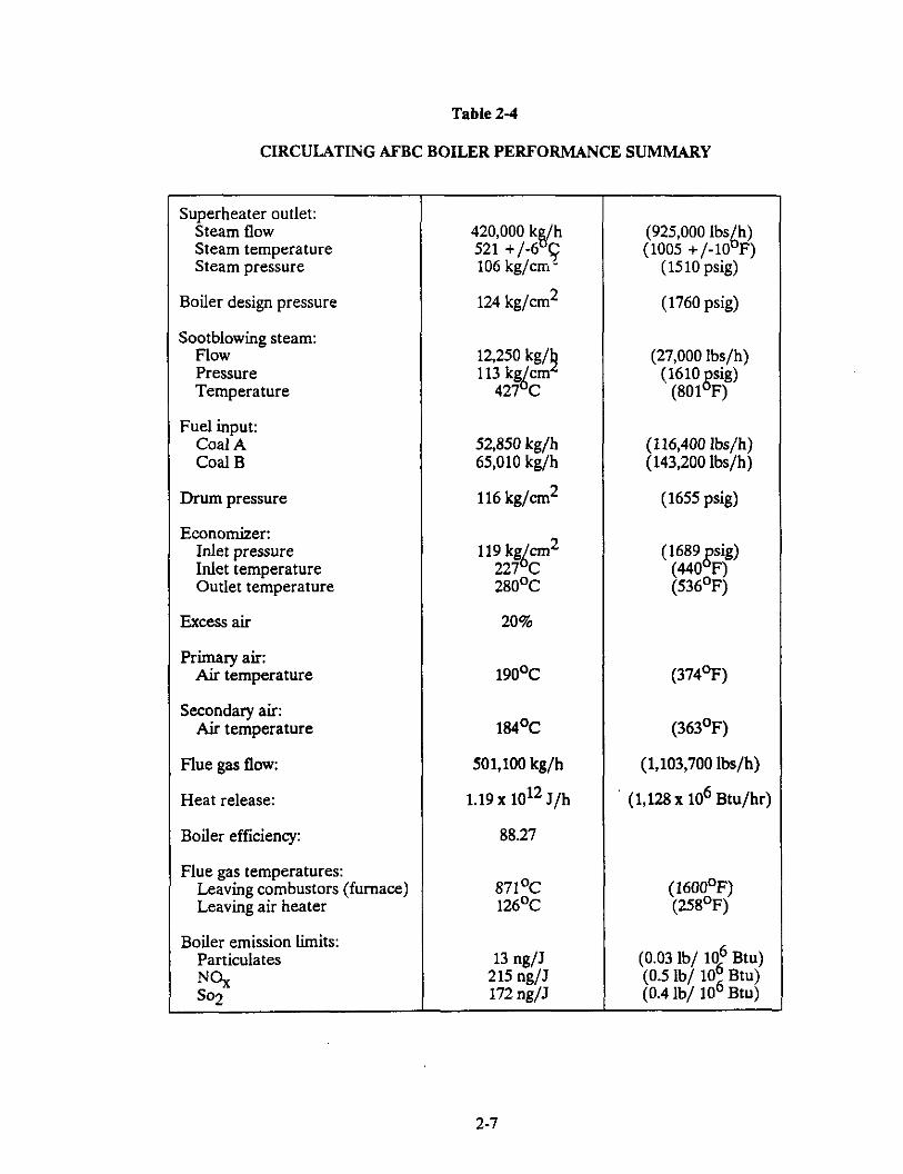
The circulating fluidized bed boiler is a coal fired, balanced draft boiler which is rated at 925,000 lb/h of superheated steam at 1510 psig and 1005’F. This fluidized bed operates in a region between that of a bubbling fluid&d bed and that of a circulating fluidized bed during start- up, and then operates as a circulating bed during normal operation. Combustion and desulfurization both take place in the bed which is cooled by waterwalls. Boiler performance, design parameters, and fuel, ash, and limestone analyses are given in Tables 2-1 through 2-4.
Several features of the Pyropower boiler described herein have been modified/upgraded in more recent offerings as a result of experience operating this boiler and others like it. These changes are reflected in the conceptual commercial design report.
The boiler consists of two combustion chambers each 22 ft.-8.25 in. wide, 24 ft.-2.75 in. deep and 110 ft. high. Each combustor has three gravity coal feed ports and four pneumatic limestone feed ports. Spent bed ash is removed through two bottom ash drain ports which lead to ash coolers. The bed distributor grid floor is membrane water-cooled and slopes toward the ash drain ports. Heat transfer in the combustors is accomplished through a combination of conduction and convection from the fluidized bed to waterwall enclosures and superheaters.
Primary combustion air is introduced through bubble caps on the bottom distributor plate and through lower wall ports located on the four combustor walls. Flow is controlled to fluidize the bed and to provide a proper air-to-fuel ratio. Secondary air, which completes the combustion and reduces NO, formation, is introduced above the primary air ports in the lower zone of the combustion chambers.
The fluidized bed is composed mostly of spent limestone, ash and calcium sulfate. Only 5 to 10 percent is unreacted limestone and unburned coal. Bed particles in the mid and upper
2-2
L-e B J E -4,--
I 43
I \i 6 z
-
I
i5 ;
Ch
I
jg: g 1
1%
- I
m I
” I
0 f .y I
L I
” I
r
I
-9 4
#-’ ii 3s 83
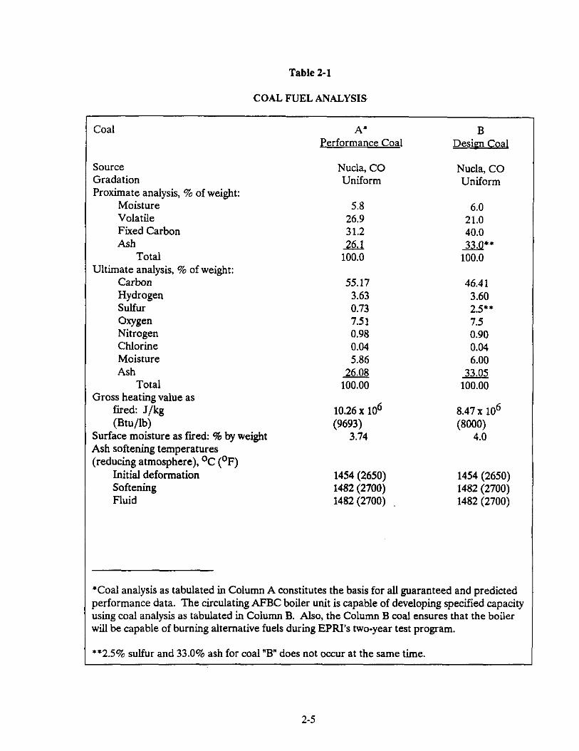
Table 2-l
COAL FUEL ANALYSIS
Coal
Source Gradation Proximate analysis, % of weight:
Moisture Volatile Fixed Carbon Ash
Total Ultimate analysis, % of weight:
Carbon Hydrogen Sulfur Omen Nitrogen Chlorine Moisture Ash
Total Gross heating value as
fired: J/kg (Btu/lb)
Surface moisture as fired: % by weight Ash softening temperatures (reducing atmosphere), OC (OF)
*Coal analysis as tabulated in Column A constitutes the basis for all guaranteed and predicted performance data. The circulating AFBC boiler unit is capable of developing specified capacity using coal analysis as tabulated in Column B. Also, the Column B coal ensures that the boiler will be capable of burning alternative fuels during EPFU’s two-year test program.
**2.5% sulfur and 33.0% ash for coal “B” does not occur at the same time.
portions of the combustion chamber are less dense and are elutriated particles exit each combustion chamber through a waterwall-cooled duct section connected to the top rear corner of each combustor. This section is connected to the hot cyclone with a refractory lined expansion joint. Non-mechanical gravity loop seals are used to recirculate particles from the cyclone to the lower zone of the combustor.
There are four secondary radiant superheaters in the upper zone of the combustors. Each is arranged horizontally, adjacent to the combustor front and sidewalls. Heat transfer is primarily by conduction and convection from the circulating bed material. Attemperator sprays are located at the inlet and outlet of the superheaters.
Boiler feedwater is heated in the economiser before delivery to the steam drum. From the steam drum, feedwater flows via downcomers to the combustor chamber waterwalls where, after heating, it is returned in risers as a steam/water mixture to the steam drum. Boiler water circulates naturally between the steam drum and the combustion chamber waterwall heat absorption surfaces.
Steam flows from the steam drum to a convection cage section at the outlet of the hot cyclone collectors. The saturated steam goes through the convection cage which forms a steam-cooled enclosure before going to the primary superheater. Primary and final superheaters are located in the convection cage. Steam flows from the primary superheater to the Gnaf superheater via radiant sections located in the upper zone of the combustion chambers.
Crushed coal, l/4 inch x 0, is stored in two 250 ton storage silos, one for each combustion chamber. Each silo bottom splits to three gravimetric coal feeders. An elongated silo outlet hopper design enhances flow out of the silo through 24 ht. chain-wheel-operated, slide-gate isolation valves to the three feeders. Coat flows by gravity from the feeders, through a rotary valve which provides a seal from boiler pressure, into three locations in each combustor - two front wag ports and a rear-wag loop seal port. In addition there is a combustion chamber motor operated isolation valve. The coal feed system operates at atmospheric pressure.
Two of the six coal feed trams, the rear-wag feeders, also have horizontal and inclined en-masse conveyors to transport coal from the feeder discharge connection around the combustor to the rear feed port located on the loop seal leg.
Each combustion chamber feed system is capable of supplying full load coal flow. Each feeder feeds coal through an inclined chute. At each feed port a plenum box is provided through which secondary air acts as a purge.
The coal feed rate is adjusted automatically, as required by steam demand, and trimmed by boiler pressure. This is done by changing the gravimetric feeder speed on a predetermined proportionate basis over the boiler turndown range.
Limestone is delivered by truck, crushed and pulverised to 150 micron size and stored in two 135 ton silos, one for each combustor chamber. The limestone flows by gravity from the silo hopper through a slide gate valve to the limestone feeder. The feeders, one for each combustion chamber, are loss-in-weight gravimetric feeders, where the rate of feed from a measured feed
2-8
hopper weight is integrated over a period of time. Flow is automatically adjusted based on coal flow and is trimmed based on SO2 content of the cyclone outlet flue gas.
Each limestone feed stream passes through rotary valves into the positive pressure pneumatic conveying system. There are four 50% capacity pneumatic trains per combustion chamber consisting of a blower, rotary valve, conveying line and injection gate. The trains are sized to feed the maximum expected limestone flow through any two of the four injection ports. There are two ports on the front wall, one on the side-wall and one on the rear wall.
Boiler Ancillarv Eauioment
Sootblowers
A total of 16 steam sootblowers are used to clean the economiser and tubular air heater surfaces. Twelve fixed position lance type sootblowers are installed in the economizer and four straight-line retractable blowers are on the air heater cold section inlet tube sheet. Soot blowing steam is provided from the primary superheater outlet steam header and reduced to 600 psig pressure. Soot blower wall boxes are located at the primary and final superheater sections of the connection zone for additional lances if required.
All external surfaces of the boiler are insulated with mineral wool or calcium-silicate to prevent face surface temperatures from exceeding 140’F based on 80°F ambient air temperature and 50 fpm air velocity. The recycle components, including hot cyclones, loop seals and gas flues are internally lined with castable refractory.
The combustor and convection section enclosures have membrane walls with external mineral fiber insulation lagged with ribbed aluminum. The economixer has an uncooled casing, with only insulation for temperature reduction.
To withstand 40 in. W.G. boiler pressure 5uctuations, the combustors and convection sections are reinforced with channel tie bars and buckstays. The buckstays are externally located outside the membrane wall insulation.
Vents are installed on all boiler pressure part high points including the steam drum, eoonomizer, superheaters and the fmal superheater outlet to the main steam line. All vents are routed to the atmosphere. Boiler drams are located at all pressure part low points and are piped to the blowdown tank. Vents and drains meet ASME Boiler and Pressure Vessel code requirements.
Three safety valves are provided on the steam drum and one on the final superheater outlet header. In addition, the main steam system has an electromatic relief valve.
Boiler blowdown is piped through throttling valves to the flash tank. Flash steam is routed to the deaerator. Flash tank blowdown drains to either a new circulating water system for makeup or to a blow down tank. The blowdown tank also receives turbine drams. Makeup is supplied from service water. Blowdown tank drains go to a storm drain and holding pond.
2-9
Startuo and duct burners
Vaporixed propane is used for plant startup fuel gas. Six burners are used to raise the nuidixed-bed temperature to 1400’F. Two propane duct burners located in each combustion chamber primary air inlet heat inlet air to 850’F during startup.
Startup and duct burners are provided with an ignitor, name failure/supervisory system, instrumented valve rack, windbox and local burner control. A common boiler master gas trip, isolation and system supply pressure control valve are provided as part of the system. In addition, for each group of three startup burners there are rack mounted pressure reducing stations.
A burner management system provides remote burner control, purge control, indication, detection, safety shutdown and annunciation of burner system malfunctions.
Boiler instruments and controls
The boiler instrument and control equipment supplied by Pyropower includes primary elements for steam and water, air and 5ue gas, and fuel and ash; transmitters; 5ue gas analyxers; engineering of control and logic diagrams; and the boiler distributive control system.
2.122 Combustion Air and Flue Gas
Primaw. Secondaw and Induced Draft Fans
The primary and secondary air centrifugal fans provide air for combustion. Primary air (PA) enters below the distribution grid, through lower wall ports around the combustion chambers, through rear-wall coal ports and through the startup burners. Secondary air (SA) enters wall ports above the primary ports and through the front wall coal injection ports. Additional smah amounts of combustion air enter through the loop seals, bottom ash coolers and the limestone pneumatic feed system. Both PA and SA intakes are from the boiler house upper building area except in colder periods when it enters directly from the outside. Both streams are heated in the tubular air heater.
The forced-draft PA and SA fans have variable frequency speed-controls. The PA fan has backwardly curved inclined air foil blades, an intake silencer and inlet vanes. The SA fan has airfoil blades, inlet silencer and inlet vanes. The SA inlet vanes control 5ow at low loads.
Proper air-to-fuel ratio is controlled by damper position, and primary air duct pressure by varying the fan speed. Secondary air duct pressure is maintained by changing fan speed and inlet vane position. Flow meters are used to measure 5ow upstream of the 5ow control dampers.
The induced draft (ID) fan is used to maintain a constant furnace pressure measured at each combustion outlet chamber. It has a variable frequency control drive and backwardly curved inclined airfoil blades.
In order to handle alternative test fuels, fan test block margins were increased from what would normally be specified.
2-10
Air Distributor and Windbox
The bottom of the combustion chamber consists of a water-cooled ah distributor grid which is used to uniformly 5uidixe the bed.
Hot primary air at a relatively high pressure 50~s through a windbox up through capped nozzles. The caps prevent bed material from back flowing into the air nozzles and windbox. The distributors are supported from lower waterwall headers and have a water-cooled membrane. A high-density, abrasion-resistant refractory protects the distributors and lower section of the sidewalls.
Air Ducts and Gas Flues
In addition to a new baghouse, three existing baghouses are used to handle the total 5ue gas flow. As a result, the duct design is more complex than a typical conventional new plant arrangement; however, the final routing is designed to minimize pressure drop and dust buildup.
Ducts and flues are designed for maximum gas velocities of 3500 fpm. Baghouse collector branch 5ues are sized for lower velocities. Between the ID fan and stack there is a long straight section to accommodate stack gas analysers.
Carbon steel plate is used for duct fabrication and reinforcement is provided to withstand design pressure 5uctuations. All duct work is externally insulated with mineral wool and ribbed aluminum lagging to prevent surface temperatures from exceeding 140’F.
Dampers are provided in the primary ah system to bypass the air heater and to control 50~s to the combustion chamber grid windbox, sidewall windbox and to the startup burners. Secondary air dampers are located in the fan inlets to maintain supply pressure and 5ow control dampers are installed in both secondary ah ducts. Manual SA dampers are located at each combustor port and at each front-wag coal injection port. The only dampers in the 5ue gas section are for baghouse bypass, isolation and 5ow balancing. The ID fan controls 5ow and pressure.
Tubular Air Heater
A tubular air heater was specified because of the relatively high pressure differentials between the combustion air and the boiler 5ue gas stream. Also a vertical-tube with downward flowing 5ue gas was desired so that tube cleaning and maintenance would be easier. Separate tube sections (upper hot end and lower cold end) are incorporated to facilitate cleaning. Flue gas 50~s inside the tubes and heats both primary and secondary air.
The air heater has an uncooled casing with external mineral wool/ribbed aluminum insulation. There are two ash hoppers with a design capacity (half full) of 36 tons each. It is sized to result in a 5ue gas outlet temperature of 258’F at boiler MCR with 80°F ambient air inlet temperature. Because the boiler is started with propane gas and sulfur capture occurs within the combustors, the SO3 dew point impact on the air heater is reduced.
2-11
The baghouse system is needed to meet particulate emission requirements. Three existing units and one new collector are connected in parallel.
The three existing units handle 48% of the CFBC 5ue gas 50~. The units are of the shake-and- de5ate type with a net operating air-to-cloth ratio of 2.7 to 1. Each baghouse has six individual compartments. They have no bypass or ventilation system. The ash hoppers are electrically heated and can hold a six hour accumulation of “B” coal flyash (including spent sorbent).
The new baghouse provides 52% of the required capacity and is also the shake-de5ate type. There are twelve individual compartments erected in modules arranged so that any one or more of the compartments may be isolated for maintenance. An internal bypass duct with three bypass dampers functions automatically during excessive or low 5ue gas temperatures. These dampers can also be operated manually during startup. The bypass is sized to handle full boiler gas 50~.
The new baghouse hoppers are also electrically heated and can store an eight hour accumulation of Type “B” coal 5yash.
The bag cleaning cycle is automatically controlled to maintain a predetermined pressure drop. Compartments are cleaned in sequence and a de5ation air fan is provided for a low-velocity purge. There is, in addition, a motor driven shaker drive mechanism in each compartment. Depending on how many compartments are bypassed, the air-to-cloth ratio ranges from 2.44 to 29.
Both existing and new baghouses are externally insulated with mineral wool covered with aluminum lagging to prevent surface temperature from exceeding 140’F based on 80°F ambient air and 50 ft/min air velocity.
A new 215 ft. high stack was installed for the CFBC. It has a single-wall all welded steel construction, is self supporting and has a base diameter of 18 ft. with a straight wag column diameter of 12 ft. Design temperature is 300°F, operating temperature is 258’F.
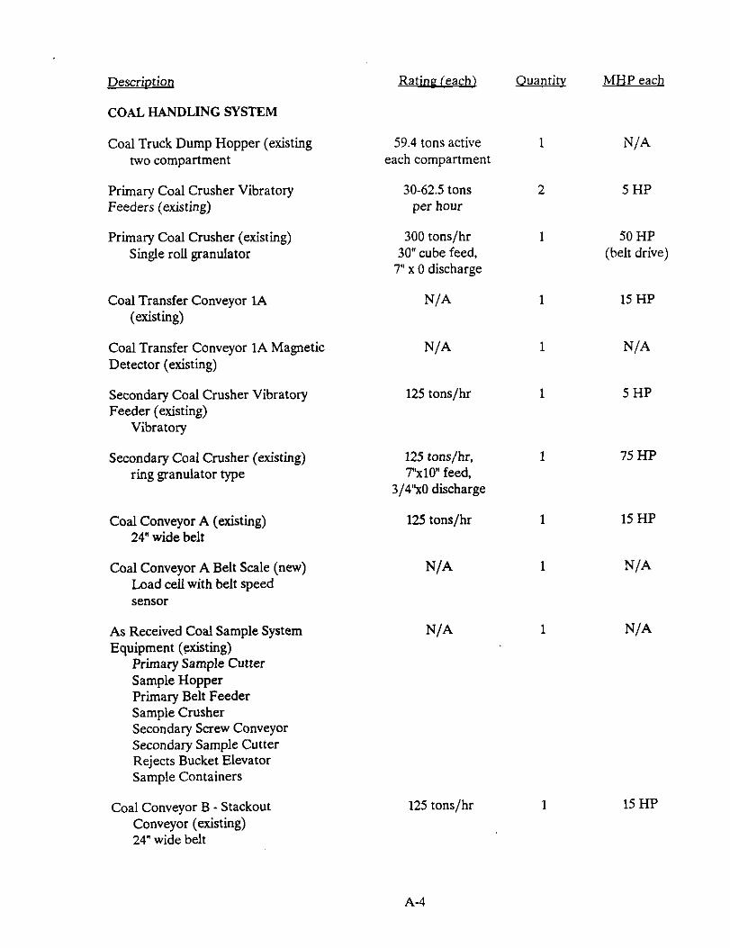
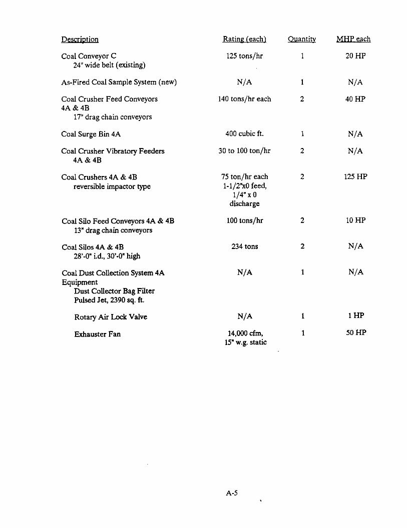
2.133 Coal Handling System
The function of the coal handling system is to provide for unloading, transporting, preparation and storing of the coal delivered to the plant. The scope of the system is from the receiving truck hoppers up to the in-plant coal silos. The fuel feed equipment from these silos to the boiler comprises the boiler fuel feed system and is discussed in Section 2.1.2.1.
Run-of-mine coal, in sixes up to 30 inches, is delivered to the plant in over-the-road coal trucks. The trucks are weighed on a truck scale at the plant. The trucks dump the coal into an unloading hopper. From the hopper, coal is fed to a primary crusher by two 50% vibrating feeders. The capacity of the feeders can be varied from 30-62.5 tons per hour (tph). The primary crusher, a single roll crusher, reduces the coal to 7 inch x 0 and discharges to a 125 tph, 24 inch belt conveyor, Conveyor 1A.
2-12
Conveyor 1A conveys the coal to the secondary crusher house and discharges to a single vibrating feeder. A magnetic detector is provided on Conveyor lA to detect any ferrous tramp metal and trip the conveyor (and the upstream equipment) before the metal is fed to the secondary crusher. The vibrating feeder feeds the coal to the secondary ring granulator crusher, where material is crushed down to 3/4 inch x 0, and then discharged onto a 125 tph, 24 inch belt conveyor, Conveyor A.
Conveyor A conveys the sized coal to the transfer house. A belt scale is provided on Conveyor A to weigh the received coal. From the discharge of Conveyor A, coal is diverted by a two-way flop gate to either the yard storage pile via a 125 tph, 24 inch belt conveyor Conveyor B, or to the boiler building 1A on a 12.5 tph, 24 inch belt conveyor, Conveyor C. An “As-Received” sampling system is provided in the transfer house to provide a representative sample of the coal delivered to the plant. The primary sample cutter is located at the discharge of Conveyor A to continuously extract samples from the coal stream. This sample flow is fed to a crusher, then further reduced in size by a secondary sample cutter, which discharges to the final sample collecting can. The excess sample rejects from the secondary sample cutter are discharged to Conveyor C.
Coal sent to the yard storage via Conveyor B is discharged to the storage pile via a lowering well which minimises coal dust emissions. Coal is reclaimed from yard storage through a hopper located at the base of the lowering well. Since the hopper is underneath the storage pile, a portion of the coal is reclaimed by gravity without the use of mobile yard equipment. The total storage capacity of the pile is 50,000 tons, equivalent to 30 days storage. From the yard reclaim hoppers coal is fed onto Conveyor C by a single vibrating feeder. Conveyor C runs from the underground yard reclaim hopper through the transfer house to the top of the boiler building.
Coal discharged from Conveyor C is sent via a diverter/splitter gate to either one or both of two 17 inch wide, 140 tph drag chain conveyors, 4A and 4B, which further elevate the material to a single 20 ton surge bin. The surge bin provides the ability to empty Conveyor C in the event of malfunction downstream.
An “As-Fired” sampling system is installed to extract a representative sample of coal discharged from Conveyor C and sent to the boilers. From the surge bin, coal is directed via a diverter/splitter gate to either one or both of two vibrating feeders. The vibrating feeders feed coal to two 75 tph, reversible impactor type crushers, where the coal is crushed down to l/4 inch x 0 size suitable for combustion in the fhtidized bed boiler. Each crusher discharges to a 13 inch wide, 100 tph drag chain conveyor, which discharge into either or both of the in-plant storage silos. Coal is discharged to each silo at three points through pneumatic operated slide gates, The two coal silos have a total storage capacity of 470 tons providing eight hours of storage.
If a crusher becomes unavailable, the remaining crusher can deliver 100 percent of the maximum coal feed rate to the boiler. However, this would require conveying coal to the plant continuously. Alternatively, the operating crusher can be adjusted to deliver 100 tph of l/2 inch x 0 product which would only require conveying coal to the plant 16 hours per day. However, the larger coal size would decrease the boiler efficiency slightly.
Fugitive dust emissions are controlled by a wet spray type dust suppression system. This system utilises a mixture of water and surfactant which is sprayed at coal transfer points from the truck hoppers to the transfer house. The solution tank and pump are located in the transfer house.
2- 13
Dust control in the boiler building coal handling facilities is accomplished by a dust collection system which consists of a single dust collector and a fan. The dust collected is discharged through a rotary air lock valve to one coal silo.
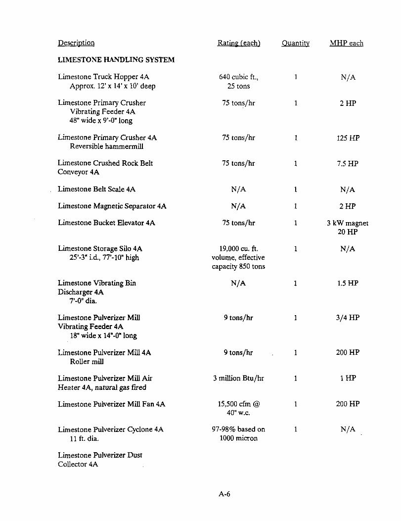
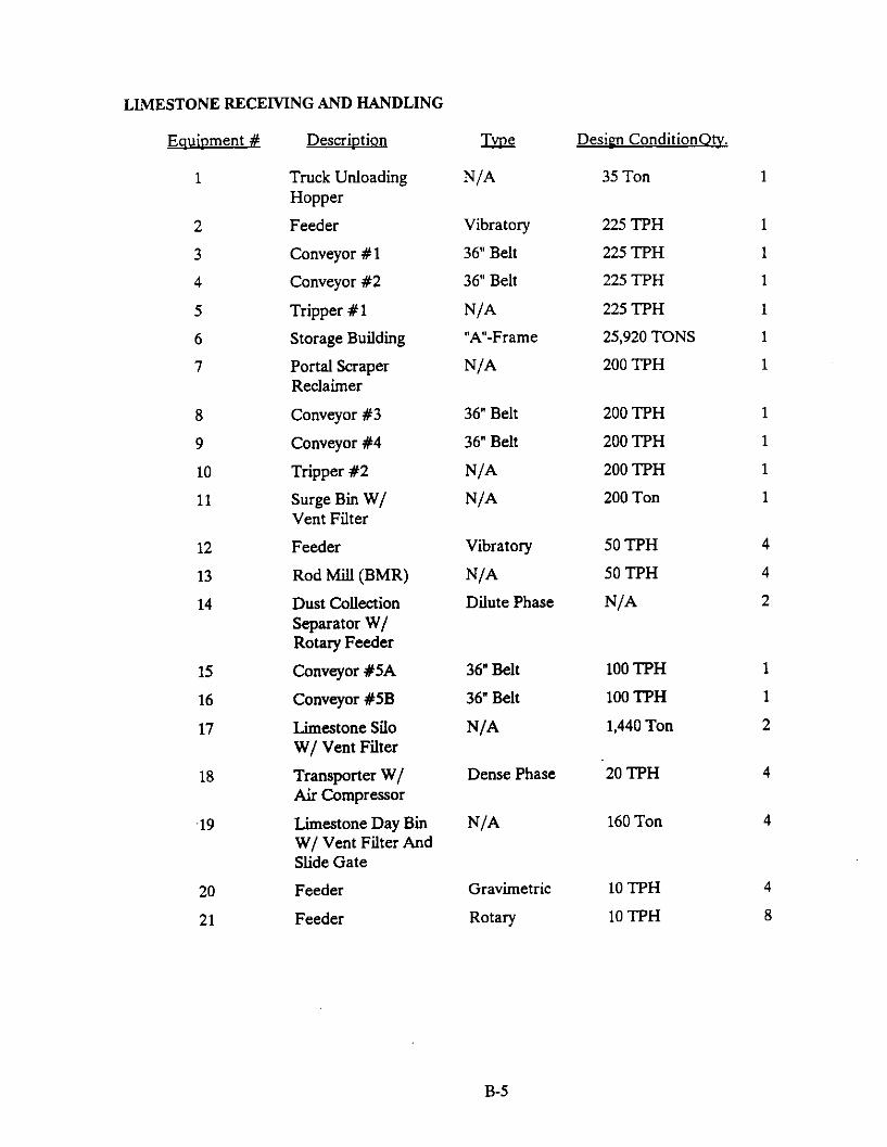
2.1.2.4 Limestone Handling System
The function of the limestone handling system is to receive, convey, store, and prepare the limestone for use as sulfur dioxide sorbent in the circulating fluidized bed boilers. The limestone is delivered to the plant in the form of raw limestone rock. For efficient u&ration, the limestone fed to the fluid bed boiler is crushed to an average size of 150 microns.
Limestone is delivered to the plant in over-the-road trucks direct from the quarry. The delivered product is run-of-mine quality with approximately 10 inch maximum lump size. Limestone is dumped into a receiving hopper which is partially enclosed by a wind’guard structure to minimize fugitive dust emissions. From the hopper, the rock is fed to a reversible hammermill crusher by a vibrating feeder at a maximum rate of 75 tph, where it is reduced to 3/4 inch x 0 sized product. The crusher discharges onto a 24 inch wide, 75 tph belt conveyor which conveys limestone from the crusher to a bucket elevator. The conveyor is provided with a belt scale to weigh the received product, and a magnetic separator to remove any ferrous tramp metal. The bucket elevator discharges.into a 850 ton capacity limestone storage silo, which serves as the reserve storage for the plant, sufficient for 70 hours of full load operation. Fugitive dust is collected at the truck unloading hopper and conveyor transfer points. The dust is collected in a pulse jet dust collector, which discharges the dust to the feed point of the bucket elevator.
From the silo, the limestone is fed to the pulverizing system which operates at a maximum capacity of 9 tph. The limestone discharges from the silo to a vibrating feeder which feeds an air swept, roller mill type pulverizer. Material flow from the silo is aided by a vibrating bin discharger at the silo outlet. A mill air fan circulates heated air in a closed circuit from thepufverixer, to a cyclone, through the fan, and back to the pulverizer. The air is heated in order to reduce surface moisture to 1 %, suitable for pneumatic conveying. In the pulverixer, limestone of small enough size is picked up and carried in the air stream. A motor driven spinner separator is included in the pulverizer to separate oversize particles picked up by the air stream and return them to the grinding zone for further grinding. Particles that pass the spinner separator are separated from the air stream in the cyclone separator. From the cyclone, the separated limestone is discharged to a pneumatic conveying system surge hopper through a rotary air lock valve.
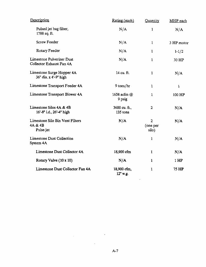
The pulverizer circulating air system is maintained at sufficient temperature by providing heated fresh makeup air. This makeup air is fed into the mill by a makeup fan which discharges through a gas fired air heater. Simultaneously, a portion of the circulating air stream is bled off to a pulse jet duct collector and exhaust fan. The pressure in the mill circulating air circuit is maintained slightly negative by the dust collector exhaust fan to minimize fugitive dust emissions. Particulate in the dust collector is then discharged to the surge hopper through a rotary air-lock valve.
From the surge hopper, the pulverized limestone is fed, by a rotary feeder, to a dilute phase pressure pneumatic conveying system. Conveying air is provided by a rotary lobe, positive displacement blower at an approximate discharge pressure of 9 psig. From the surge hopper, the pulverized limestone is conveyed to one of the two limestone silos in the main boiler vented from the silo through a pulse jet.bin vent filter (one per silo). Each limestone silo supplies the limestone
2-14
feed system for one of the combustion chambers. Each silo has a capacity of 135 tons, equivalent to twelve hours full load operation with the performance coal (0.73 percent sulfur.)
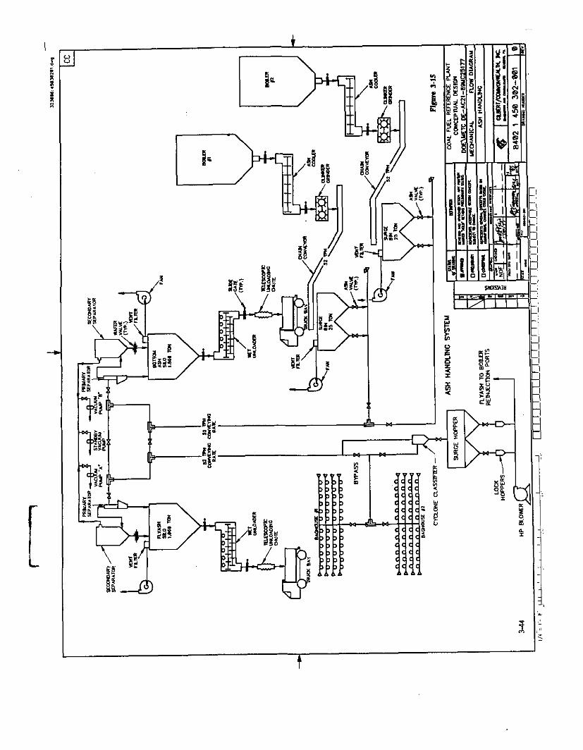
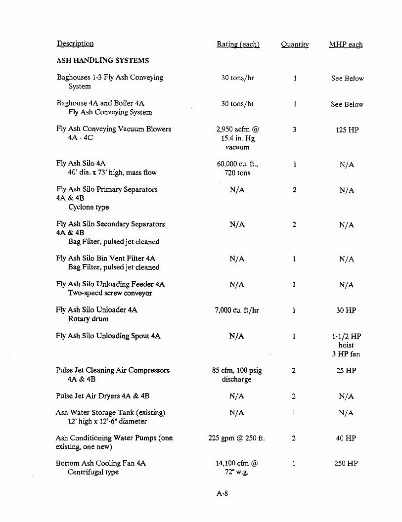
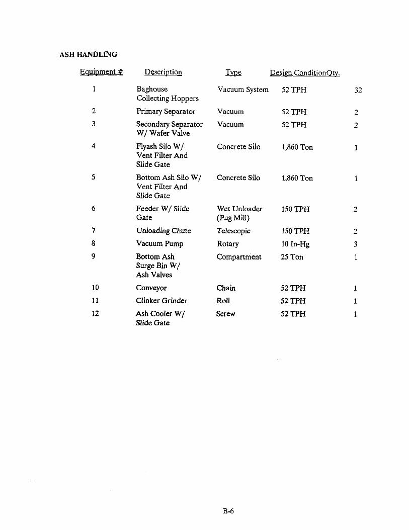
2.125 Ash Handling System
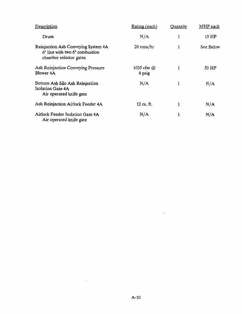
The ash handling system consists of two main sub-systems: the bottom ash system and the fly ash system. The function of the bottom ash system is the removal, classification, cooling, conveying, storage and disposal of the ash from the combustion chambers. The ash is handled and stored in a dry state. The material is conveyed pneumatically by a vacuum system. An ash reinjection system is provided to convey bottom ash from the silo back to the combustion chamber to provide the necessary initial inventory of fluid bed material for boiler startup. The fly ash system functions to remove, convey, store and dispose of the fly ash collected in the baghouse hoppers, boiler economizer hoppers and the air heater hoppers. This material is also conveyed by a vacuum pneumatic conveying system. The bottom ash and fly ash are stored in separate silos.
Bottom Ash &stem
The bottom ash system includes all equipment from the combustion chamber sidewall ports to the ash silo and truck loading facility. In addition, an ash reinjection system is included which conveys ash from the bottom ash storage silo back to a rear wall reinjection port on each combustion chamber to provide sufficient bed material for boiler startup.
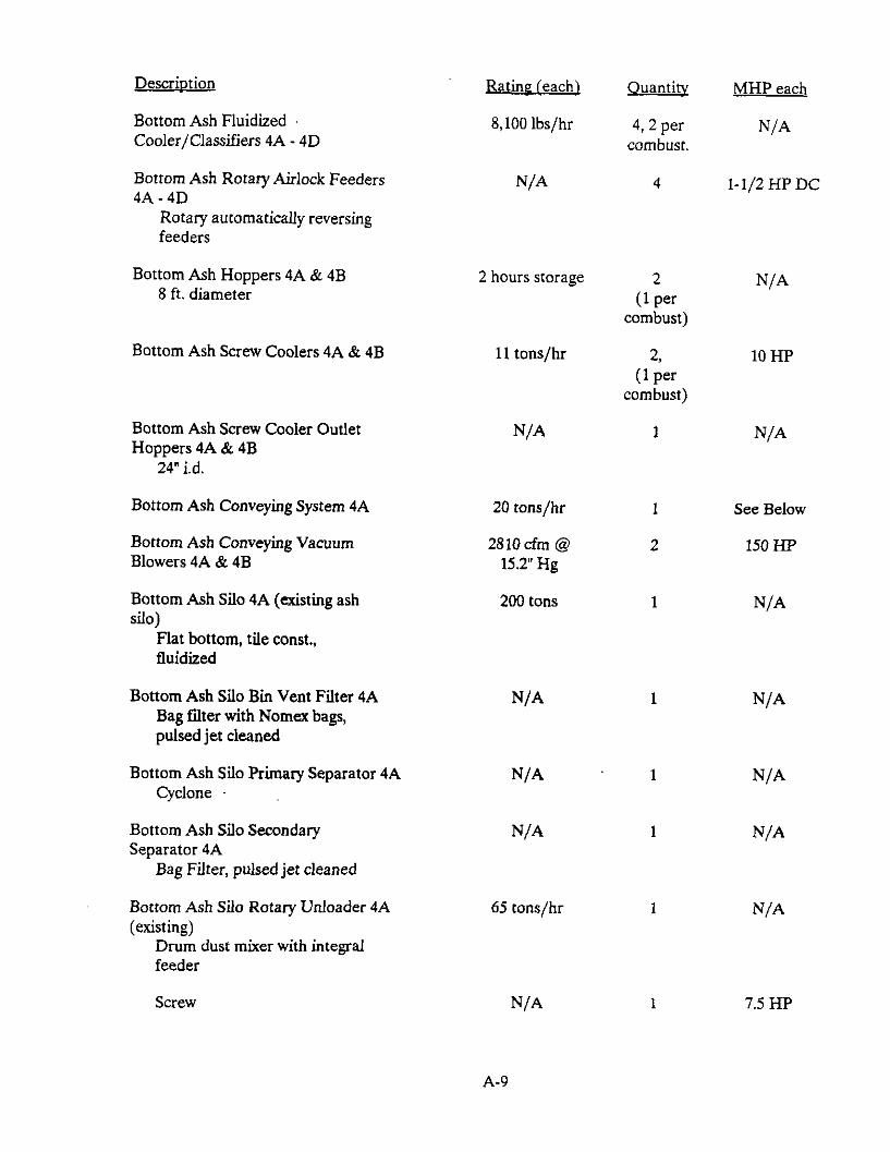
Hot bottom ash, at approximately 1600°F, is removed through bottom ash ports located on the lower side of each combustion chamber. From these ports the plant bed ash is fed to four 100 percent capacity ash coolers (2 per combustion chamber) which cool and classify the ash. Fluidizing air aids material flow from the ports to the coolers. Each ash cooler is rated at 8100 lb/h. Heat in the ash is transferred to cool combustion air and cooling water. The cooling air for all four coolers is supplied by a single centrifugal cooling air fan which discharges directly into all four ash coolers without any pre-heating. The cooling air exits the top of the cooler with the classified bed material and enters the combustion chamber through pressure equalization ports.
Cooling water to the ash cooler is circulated through cooling coils in a closed loop and the heat from the ash is transferred to the low pressure feedwater system.
Each pair of ash coolers discharges through a rotary valve to a surgebin; there is one surge bin per combustor. The rotary valve has a variable speed drive which is controlled based on bed inventory in the combustor. The surge bin is mounted on load ceJls to provide indication of the bottom ash production rate. Each surge bin discharges to the vacuum pneumatic conveying system through an ash intake valve. A water-cooled screw cooler is also provided as an alternate to the vacuum discharge system. This cooling screw would be used in the event that 1) one of the ash coolers is out of service; 2) high ash and high sulfur fuel is being burned, causing the ash flow rate to increase; and 3) the discharge temperature of the ash to the surge bin exceeds 400’F. Upon detection of high temperature in the surge bin, the screw cooler is automatically placed in operation. Cooling water to the cooling screw is supplied from the same system as the cooling water for the ash coolers.
The vacuum pneumatic system conveys ash from the surge bins (or the cooling screws) to the bottom ash storage silo. ASh is separated from the conveying air by a primary cyclone separator
2-15
followed by a pulse jet type bag filter. Conveying air is handled by two 100 percent motor driven vacuum exhausters. Both the bottom ash silo and the exhausters are existing equipment. The capacity of the bottom ash silo is 200 tons. Three discharges from the bottom ash silo are included: one to a rotary dust conditioning unloader, one to a dry unloading spout and one to the ash reinjection system. The rotary unloader mixes water with the ash for duct control and discharges to an open top truck.
During boiler startup, an initial inventory of fluid bed material is required in the combustion chamber. This material is supplied by the ash reinjection system. The ash reinjection system is a pressure type pneumatic conveying system with a capacity of 20 tph. The system includes a pressure air lock feeder vessel to transfer ash from the silo into the pressurized conveying line. The ash is then discharged into either combustion chamber through a single reinjection port in the lower rear wall of each combustor.
Flv Ash Handling System
The fly ash handling system includes all equipment from the baghouse hoppers, economizer hoppers and air heater hoppers to the fly ash silo and truck loading facility. Two 27 tph systems are provided, one serving the new baghouse, economiser hoppers and air heater hoppers and one serving three existing baghouses.
Ash is withdrawn from each hopper through a fly ash intake valve. Two parallel trains of cyclone separators and bag filters separate the ash from the conveying air. A cross-tie with valve is provided upstream of this separating equipment for enhanced system reliability in the event one tram is unavailable. Conveying power is supplied by three vacuum exhausters, one for each separating tram, with a common spare.
The fly ash storage silo is a mass flow design with a capacity of 900 tons. Ash is discharged from the silo to a surge hopper by a screw feeder and operates in a batch mode. From the surge hopper, ash is discharged to trucks through either a dry unloading spout or a rotary dust conditioning unloader.
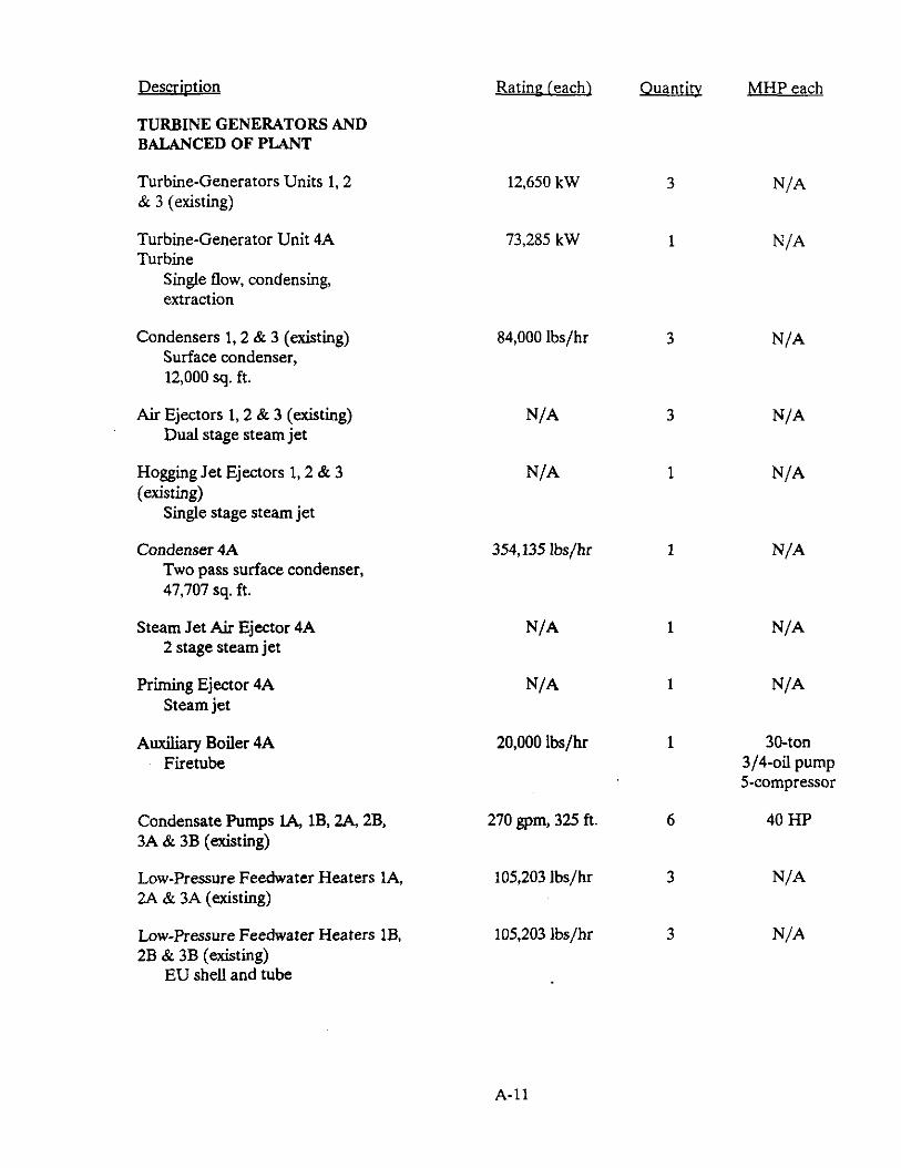
2.1.2.6 Turbine Generators and Main Cycle
A total of four turbine generators are included in the plant. Three of the turbines (Units 1,2, & 3) are the existing machines originally installed with the stoker boilers. ‘The fourth turbine (Unit 4) was installed with the CFB addition to the plant along with the necessary auxiliaries.
Units 1-3 are identical 3600 t-pm, multistage, nonreheat condensing turbines rated at 12.65 MWe at 1.5 in. Hg backpressure. Throttle steam conditions for these turbines are 600 psig and 825’F. The original installation utilized four stages of uncontrolled extraction for feedwater heating. This extraction steam supplied two low pressure feedwater heaters, a deaerating heater and a high pressure feedwater heater. The highest extraction stage has been capped and the high pressure feedwater heaters removed from the cycle. Each of the existing turbine generators include their own auxiliaries, turning gear, lube oil system, DC generator exciter and turbine governor.
The new Unit 4 turbine generator is a 3600 ‘pm, multistage, single automatic extraction, non- reheat condensing machine rated at 73.4 MWe. Steam is supplied from the ACFB at inlet conditions of 1450 psig and 1000’F. The Unit 4 automatic extraction supplies steam to the Unit 1,
2-16
2 and 3 turbine generators. Five stages of uncontrolled extraction supply steam for feedwater heating to two low pressure feedwater heaters, one deaerating heater, and two high pressure feedwater heaters. The new turbine generator includes the following auxiliaries: stop-throttle valve and governing control valve, automatic extraction control valve, electro-hydraulic control system, lube oil system, gland sealing system, turning gear, hydrogen cooling system and seal oil system.
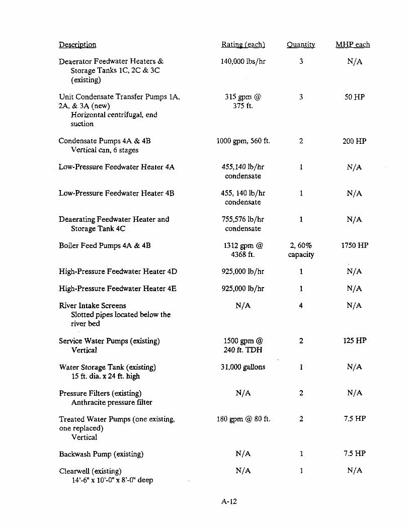
As previously indicated, each of the existing Units 1.2, and 3 included their own complete cycle equipment such as feedwater heaters, condenser, condensate pump, etc. This equipment was retained in the modified plant cycle up to the deaerating feedwater heaters. From the Unit 1.2 and 3 deaerating heaters, the feedwater is pumped to the new Unit 4 deaerating feedwater heater.
2.1.2.7 Additional Balance of Plant Equipment
Each of the 4 turbines discharge to a dedicated condenser. Heat from the exhaust steam is rejected to the circulating water which is then cooled in cooling towers. Units 1,2 and 3 are served by an existing common cooling tower and Unit 4 is served by a new cooling tower.
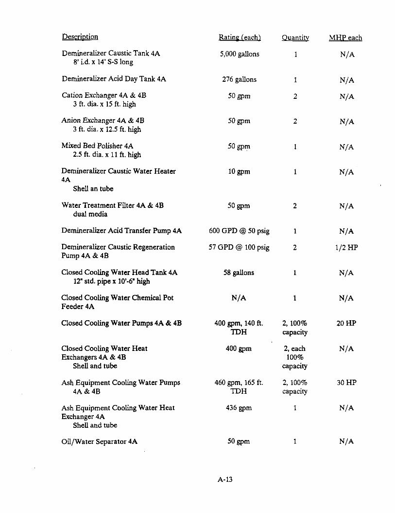
Makeup water for boiler makeup, cooling tower makeup, fire protection and other miscellaneous plant services is supplied from the San Miguel River by the existing service water pumps and stored in an elevated storage tank. Water for boiler makeup is treated by a demineralizer system consisting of a cation exchanger, anion exchanger and mixed bed polisher train, The deminerahzed water is then sent to the Unit 4 condenser hotwell or the Unit 4 condensate storage tank.
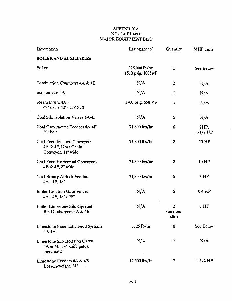
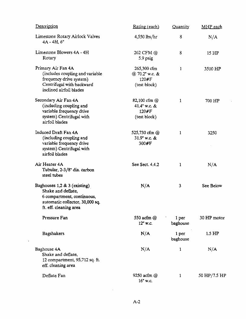
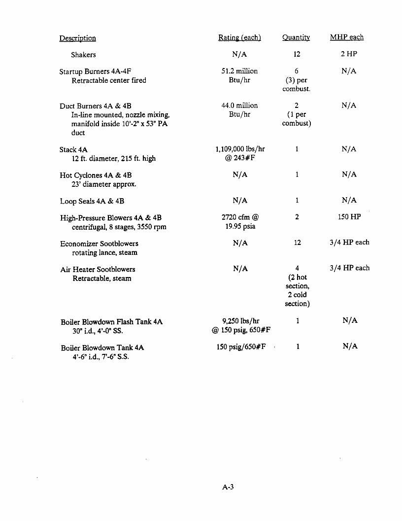
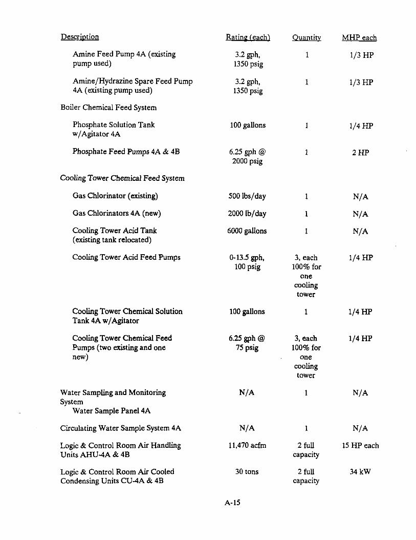
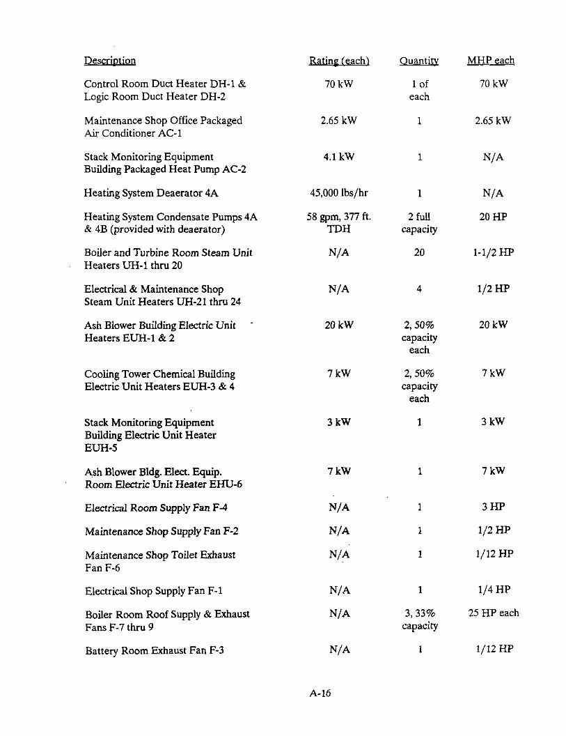
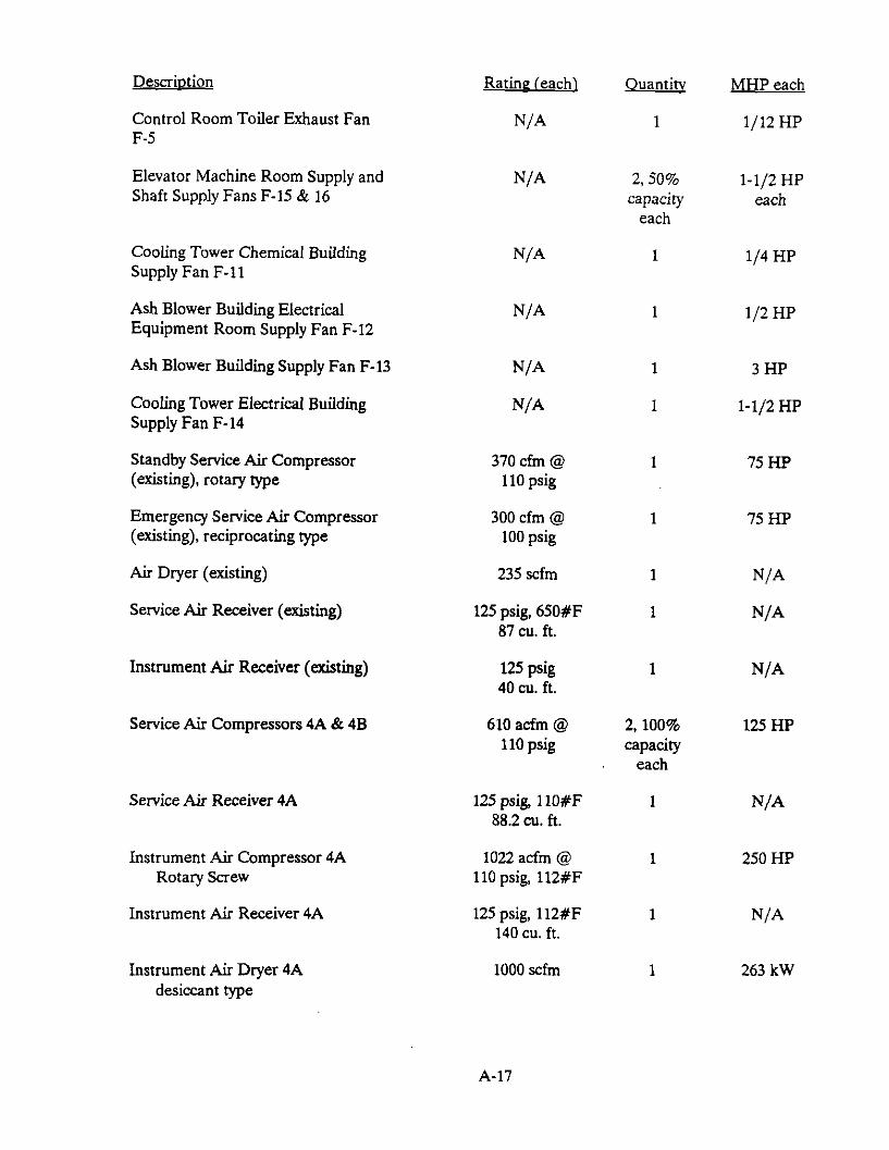
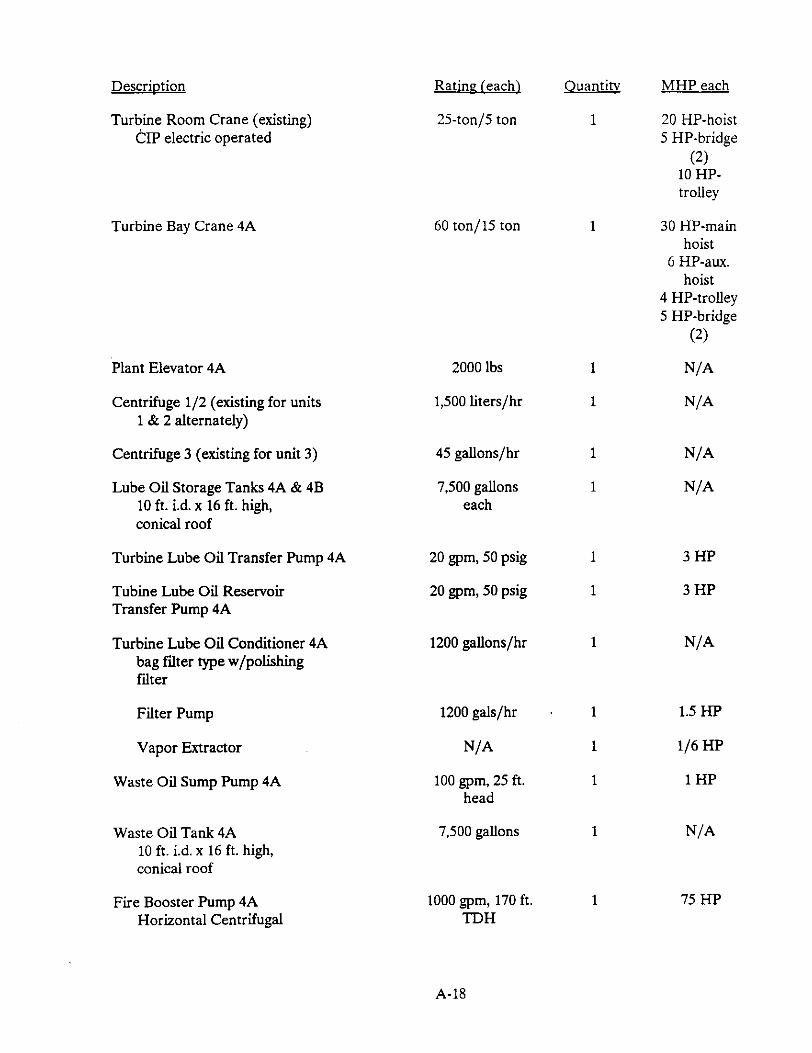
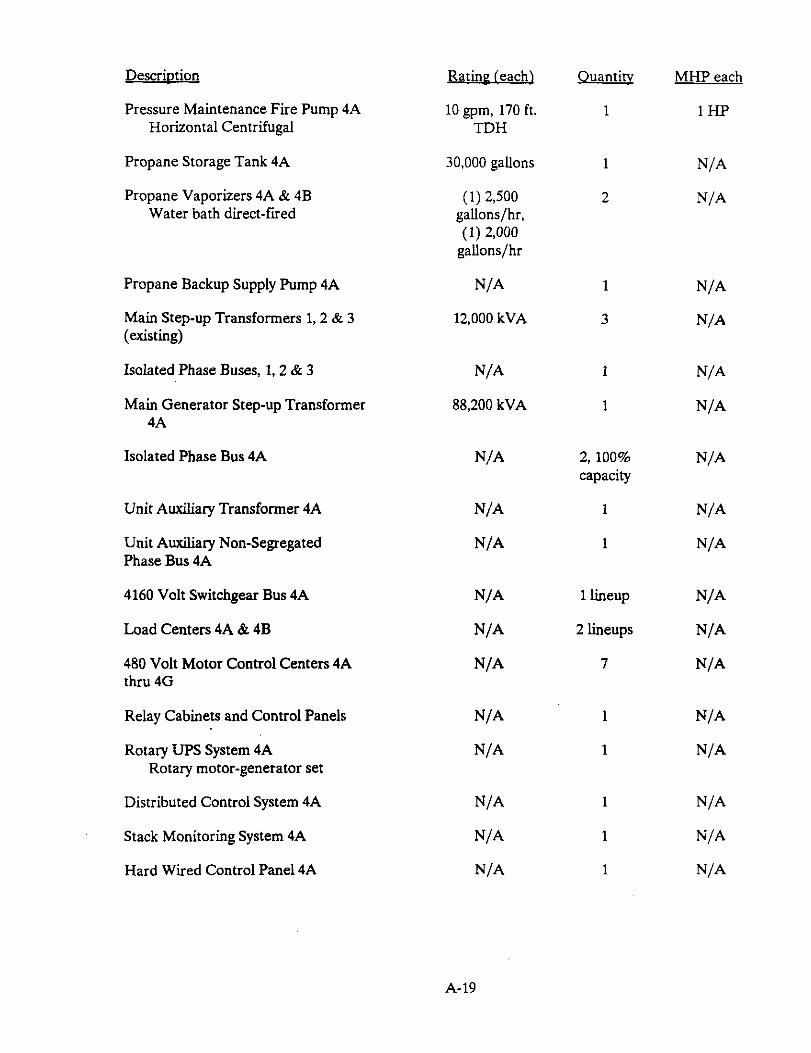
Additional details of the balance of plant equipment are reflected in the equipment list in Appendix A.
2.1.2.8 Plant Contra1 and Instrumentation
The new control system for the Nucla Station was designed to integrate the old and new systems. Obsolete pneumatics were replaced with a microprocessor based control system which could easily be changed after operating experience was gamed, and system diagnostics were incorporated to monitor operation and collect data for the test program.
The plant is operated and controlled using a distributed, microprocessor based system referred to as the Distributed Control System (DCS). Operator interface is with CRT displays and keyboard terminals, segregated in a manner to provide control by unit number, system and function. Combustion, feed water, ash handling and the baghouse are controlled with this analog system and loops are capable of either manual or automatic operation via CRT/keyboard interface. Basic control mode, however, is automatic with operator override. Safety systems are hardwired to trip.
A digital control system, also part of the DCS, controls fans and pumps with a microprocessor based system providing sequential, digital interlock logic control. Information is displayed on the operator CRTs and also recorded on hard copy printout. Loop integrity is provided so that one loop failure will not affect others.
Alarms, grouped by systems, which require operator attention are displayed on CRTs and on hard copy printout, Design is such that operators are not affected by unimportant alarms. CRT
2-17
pictorial graphics show alarm points and local annunciators are provided showing any actuated local alarm.
The DCS gathers and displays the following basic information:
. Alarms
. Events recording for normal plant events
. Sequence of events recording and display of plant upsets
. Scanning of analog and digital inputs
. Logging of trends called for by the operator
. Logging of daily and hourly summaries of averages, totals, etc. of analog inputs
. Graphic dispiay capabilities upon demand by the operator
The following systems are integrated with the DCS and controlled by the plant operator from the control room:
. Boiler
. Burner management system
. Main interlocks and purges
. Ash handling
. Baghouse
The pre-boiler water treatment system is controlled outside the control room locally by programmable controllers. Some pneumatic systems are used for drives, valves, etc. and these are local, single closed loop systems with electric/pneumatic positioners.
A new turbine control system was purchased with the Unit 4 turbine-generator. Startup is from the main control room.
Pyropower furnished the boiler furnace safety and fuel automation system to ensure that the ignition system and damper drive were correctly interfaced with the boiler. They also were responsible for control philosophy and logic. Basic control mode is “supervisor manual.” Redundant instrumentation is employed where necessary to minimize nuisance trips.
The four CRT/keyboard control consoles were purchased with the main control system and are installed in the new plant control room. One CRT/keyboard engineer’s console is in the new logic room, and the distributed control equipment is in a new remote logic room. The main logic room located beneath the new control room contains the protective relay, turbine-generator, and coal and limestone feeder cabinets.
2.13 -8
Even though the plant output was increased from 36 MWe to 110 MWe, preliminary reviews by both the U.S. EPA and the Colorado Department of Health disclosed that no significant environmental impacts would be associated with the Nucla project. This was substantiated in tests done with Nucla coal at a 1.5 MWe test facility and later during plant operation.
2-18
2.13.1 Flue Gas
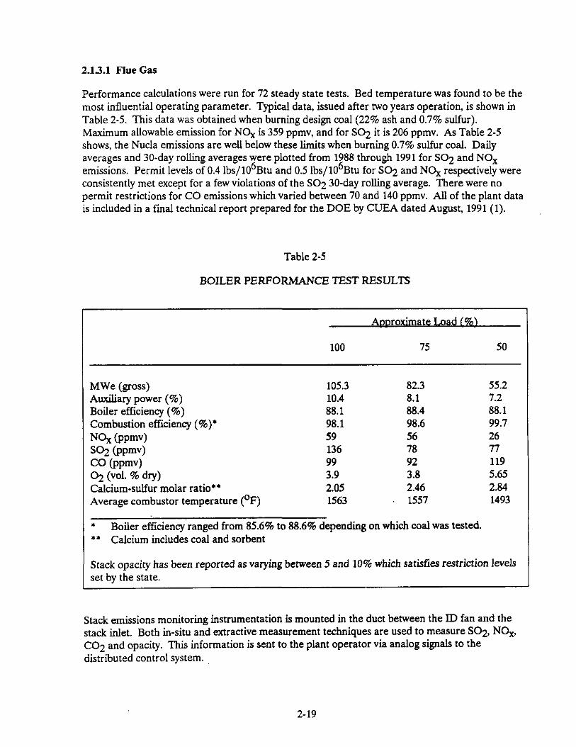
Performance calculations were run for 72 steady state tests. Bed temperature was found to be the most influential operating parameter. Typical data, issued after two years operation, is shown in Table 2-5. This data was obtained when burning design coal (22% ash and 0.7% sulfur). Maximum allowable emission for NOx is 359 ppmv, and for SO2 it is 206 ppmv. As Table 2-5 shows, the Nucla emissions are well below these limits when burning 0.7% sulfur coal. Daily averages and 30-day rolling averages were plotted from 1988 through 1991 for SO2 and NO, emissions. Permit levels of 0.4 lbs/106Btu and 0.5 lbs/106Btu for SO2 and NOx respectively were consistently met except for a few violations of the SO2 30-day rolling average. There were no permit restrictions for CO emissions which varied between 70 and 140 ppmv. All of the plant data is included in a final technical report prepared for the DOE by CUEA dated August, 1991 (1).
t Boiler efficiency ranged from 85.6% to 88.6% depending on which coal was tested. ** Calcium includes coal and sorbent
Stack opacity has been reported as varying between 5 and 10% which satisfies restriction levels set by the state.
Stack emissions monitoring instrumentation is mounted in the duct between the ID fan and the stack inlet. Both m-situ and extractive measurement techniques are used to measure SO2, NO,, CO2 and opacity. This information is sent to the plant operator via analog signals to the distributed control system.
2-19
The stack emissions monitor functions are:
Scanning, conversion and iinearization of measured emissions concentrations Computation of pollutant emissions Reduction of emission data Hourly determination of periods of excess emissions of SO2 and NO, Determination and logging of excess opacity emissions Hourly recording events Data logging; daily and monthly Analyser interface to allow off-line calibration and standardization
Samples of bottom ash and fly ash are manually taken and analyzed in on-site laboratories.
The plant wastewater system has not been modified, and hence no new analysis equipment was needed.
2.132 Ash Solid Waste
Solid wastes consist of bed drain or bottom ash, and fly ash collected in the bag collectors.
A material balance done during acceptance tests shows the relative amounts of the wastes collected:
&g& (lb/h) Q&l Limestone 108.75 3.59
Air Total 1,140.51 1.252.85
OutDut (lb/h) Flue Gas 1,225.47
lT!bQ!l 23.59
Bed Drain 3.79
Total 1,252.85
The U.S. DOE collected field data on the engineering and environmental performance of disposed solid waste generated by the Nucla facility.
A test cell approximately 100 feet square and 8 feet deep was constructed adjacent to a landfii located 10 miles south of the Nucla station. ‘The cell was filled with ash conditioned with water to prevent dusting resulting in an average moisture content of 30 percent.
The test cell is instrumented to provide data on the water balance at the site and to permit monitoring of water quality parameters. A meteorological station measures temperature, precipitation, humidity, insolation, wind speed and direction. A Parshall flume provides data on surface runoff, and access tubes allow measurement of soil moisture content using a neutron attenuation probe. Leachate quality is monitored by sampling porous-cup lysimeters installed at the site. The cell will be monitored for three years to determine physical and chemical changes in the ash.
Chemical analyses of the waste and soils have been completed and core samples were taken and analyzed. The results to date have demonstrated that landffi construction using FBC wastes is straight-forward with no problems encountered with rapid set-up of the conditioned waste or with excessive dusting at the site.
2-20
2.1.4 Problems Exoerienced/Overcome
In the acceptance tests using design coal (22% ash and 0.7% S), nearly all performance guarantees were met. Only fan performance and flue gas duct pressure losses did not meet guarantees. Problems experienced fell into three categories: typical startup/shakedown problems, problems related to construction errors and scale-up problems:
2.1.4.1 Start-up problems
Throughout the commissioning period the boiler experienced typical startup problems. These included coal feeder trips, steam leaks, valve linkage problems, valve packing leaks, generator trips and synchronization problems, propane feed difficulties, and steam line expansion interference. These problems were not specifically related to the type of technology being demonstrated.
2.1.43 Construction related problems
The two major construction problems incurred on this project involved boiler casing leaks and steam leaks on superheater field welds caused by weld contamination. These problems were discovered early in the program, repaired, and steps were taken to prevent their reoccurrence.
2.1.43 Scale-up problems
Problems related to design scale-up from previous smaller boilers were of more concern and some became chronic; however, none were so serious as to affect the ability to operate or to obtain good data except for the primary air fan which did not meet design specifications. The fan was modified in October, 1989 so that a key test variable, primary-secondary air ratio, could be controlled. Backsifting of bed material from the furnace into the windbox was a problem which was alleviated, but never eliminated, by increasing air flows. A reinjection fine had to be installed to return material to the loopseal that had backsifted into the windbox. At various locations, the bubble cap design was modified to address backsifting, which was worse at low load operation but occurred at all conditions.
Although the limestone feed system improved with operating experience, weigh feeders, leaking rotary valves, erratic weigh signals and shaker motor failures persisted throughout the test program. By contrast, the coal feed system was reliable and required relatively low maintenance.
The bottom ash handling system experienced several problems, which involved sizing and material handling in general. Changes were made to correct these problems, including amendment of the ash cooler to classifier, modifications to the ash cooler discharge lines and modifications to increase ash handling capability. Controls changes were also made to facilitate operation with the physical system changes.
Problems persisted with drum level control, especially during startup and load change, despite changes in operating logic and increased operator attention. This placed a burden on the propane startup and make-up water systems. These drum level control problems were related primarily to the fact that a single drum was provided to serve two combustion chambers. Differences in heat
2-21
absorption in the two chambers under these operating conditions occasionally caused an imbalance in water 50~ into the drum, resulting in drum level control problems.
Instrumentation problems, other than drum level control, included faulty oxygen analyzers, errors in combustion air flow indication and bed pressure taps which plugged. New oxygen analysers were installed which operated successfully.
Inadequately designed air dampers and actuators were a problem until the dampers were modified and larger actuators were installed.
Refractory durability, although it improved, remained a concern and was monitored throughout the test program. Sections of refractory were replaced on the rear wall of the combustor and in the conical portions of the cyclones and several areas of the loop seals. Surface spalling was also evident in the combustor.
In September of 1987, an incident occurred which resulted in a 10 week outage. One of the two combustion chambers overheated when unburned coal ignited during a fan cooldown following a waterwall tube leak. This caused structural damage due to downward differential expansion between the two chambers. No metallurgical damage was sustained by boiler pressure parts, and after repairs were made, no further problems associated with the deformation were experienced.
The limestone crusher was not able to vary the sorbent particle size and as a result, a finer-than-desired particle was produced. A modification to the crusher will be made to solve the problem.
2-22
2.2 ,SCALE-UP PHILOSOPHY
The intent of the Reference Plant design effort is to portray a commercial power plant with attributes considered important to the utility industry. The system designs and equipment selections are chosen using operating availability, overall cycle efficiency and cost effectiveness in the same manner as would be done in a commercial plant design. The pulverized coal (PC) fired power plant with flue gas desulfurization design is considered as the utility standard, from which commercial comparisons are made. Design assumptions are therefore based on criteria used for PC plant applications, except where the new technology portions require special consideration.
A series of assumptions concerning generic and geographical features has been made to define the Reference Plant as a guide for designs and cost estimates. Similar assumptions can also be made for future commercial versions of other Clean Coal plants which will permit valid comparisons to be made. These assumptions are documented in Section 3.1.1, and provide a common base for present and future comparisons. By documenting these assumptions, it also becomes possible for individual utilities to modify the assumptions for their own specific situations.
The plant is a single unit on a new, or grass roots, site. The facilities necessary to support the plant on the site are included, and are sized for one unit. The single unit plant may not be the reasonable choice in many actual situations, since many sites are multi-unit; however it provides a total plant cost picture, as well as a logical and understandable basis for evaluation purposes and comparison of different technology plants.
A site location has been chosen so that geographical assumptions can be made. Likewise, specific coal and limestone characteristics have been selected to defme the equipment to be used in the plant. A description of the site, and the coal and limestone are included in the referenced Section 3.1.1.
To provide a sound basis for the ACFB combustor design, and for the plant which utilixes the combustor, a specific manufacturer was chosen. The logical choice was Pyropower, since they supplied the ACPB for the Nucla Project. There are significant design differences between ACFB manufacturers which affect the plant design and operation. However, a specific combustor design is required to complete a conceptual plant design, and the manufacturers are generally competitive in cost and performance, since CPB technology is now “market driven”. As other Clean Coal projects are initiated, it will be of interest to make a direct comparison of different manufacturer’s designs. It will also be interesting to determine how various approaches to combustor design affect upper limits of unit size, load change ability, minimum load capability, reheat configurations, and other design features.
The Pyropower boiler is classified as an atmospheric pressure, circulating fluidized bed boiler. Traditionally, fluidized bed boilers have been classified as either ACPB or bubbling bed (BB). The difference between the two types primarily relates to the fluidizing velocity used. Bubbling beds normally operate at 2 to 8 ft/s fluid&g velocity and the beds remained in a specific area of the bottom of the combustor, while circulating fluidized beds operate from 12 to 30 ft/s, thereby elutriating and recirculating most of the bed. However, this distinction is blurring (2). As outlined in the reference, there now appear to be at least four categories, namely bubbling bed units with solids recirculation, units with internal circulation, hybrid designs combining one or more fluidizing
2-23
regions and full fledged ACFBs. It is expected that distinctions wiIl be further reduced as operating experience is gained by the manufacturers.
The type of AFB boiler chosen/offered for a particular application will be vendor specific as well as fuel and use specific. The requirement to:
. burn/incinerate certain waste fuels;
. operate for extended periods at low loads;
. change load quickly;
. provide a large furnace size;
. achieve high efficiency using high presure/temperature steam with reheat, or;
. meet other user requirements,
may alter the competitive price range of vendors based on the configuration they offer. The current trend for large unit sixes (above 50 to 100,000 lb/h) has been toward the CFB, with some exceptions.
Placement of heat transfer surface clearly separates some vendors into categories with distinct differences. In small CFB units (less than 50 to 100,000 lb/h), this is less of a problem, i.e. surface can be accommodated in several ways because the wall surface to wmbustor volume ratio of the unit is large. As unit size increases, this ratio decreases, and vendors have elected to either employ external heat exchangers (EHE’s), or surface which extends from the walls of the wmbustor. Wall surface is sometimes maximixed through the use of cyclones constructed of waterwall heat transfer surface.
Pyropower and some other vendors have elected to proceed with the use of heat transfer surface internal to the wmbustor. Designs have evolved from conventional headered tube banks and wingwalls to OmegaTM (Pyr o p ower) surface which provides superior erosion protection. Lurgi and ABB/CE started and have continued with the EHE and claim that this design approach is better for temperature control, turndown and accommodating reheat. Foster Wheeler has recently offered a version of the EHE called “INTBEX” which is mechanically integral with the combustor. FW claims advantages of this design over the patented EHE. design offered by others. ABB/CE offers a similar arrangement, where the walls of the EHE are integral with the combustor.(3) Pyropower claims that the “simpler” and lower cost wingwall (now improved OmegaTM surface) approach is better. The Omega Th4 surface is described elsewhere in this report.
Foster Wheeler and Lurgi both offer steam/water cooled cyclones. Because only a thin layer of protective/sacrificial refractory is needed, start-up to full load times are reduced, and start-up time is limited by temperature gradients in thick walled pressure parts, similar to a conventional boiler. Integrating the cyclone into the boiler circuitry improves structural and thermal stability and reduces the number of required expansion joints and boiler radiation losses. Pyropower has retained their successful approach of using a full refractory-lined cyclone. The advantages of the EHE, cyclone design approach, and the approach placement of heat transfer surface with regard to
2-24
cost, operability and reliability will become apparent as more experience is gained with CFB plant operation.
The nominal size chosen for the ACFB Reference Plant is 400 MWe. This has been selected as being the most logical candidate size for this technology, considering factors such as technology scale-up and utility growth rate needs. The plant utilizes two boilers, each sized to produce one-half of the required steam flow, or 200 MWe equivalent. This selection was made for the following reasons:
. The 200 MWe size is presently available with commercial warrantees, even though units of this size and technology do not presently have significant operating experience. The warrantees offered may be different than those offered on mature technology equipment. Since there is a lack of operating experience at this size, there is a good chance that some if not all manufacturers will either offer warrantees with escape clauses, or equipment that is designed very conservatively, with higher margins and/or additional assemblies, to give the manufacturer some protection if the equipment does not meet expectations. This results in more expensive installations than would be expected if the equipment design was mature. However, the added cost on a 200 MWe size boiler would be small compared to what would have to be added on a 300 MWe size boiler to mitigate risk at the size.
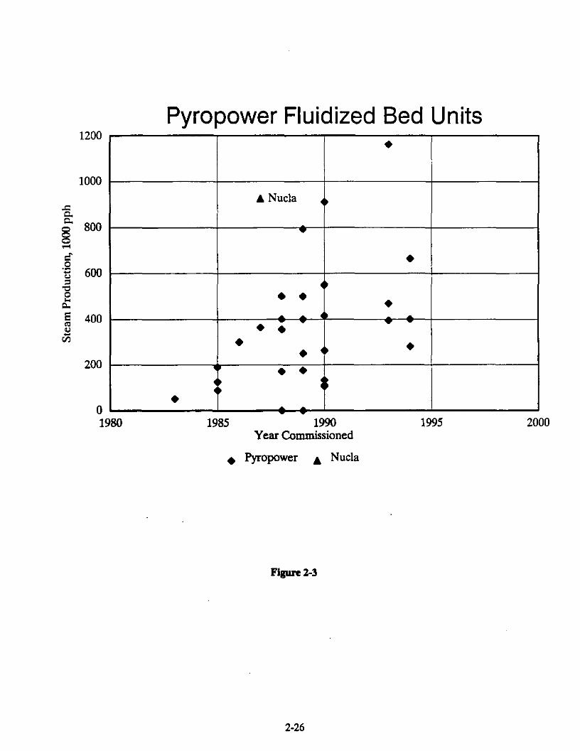
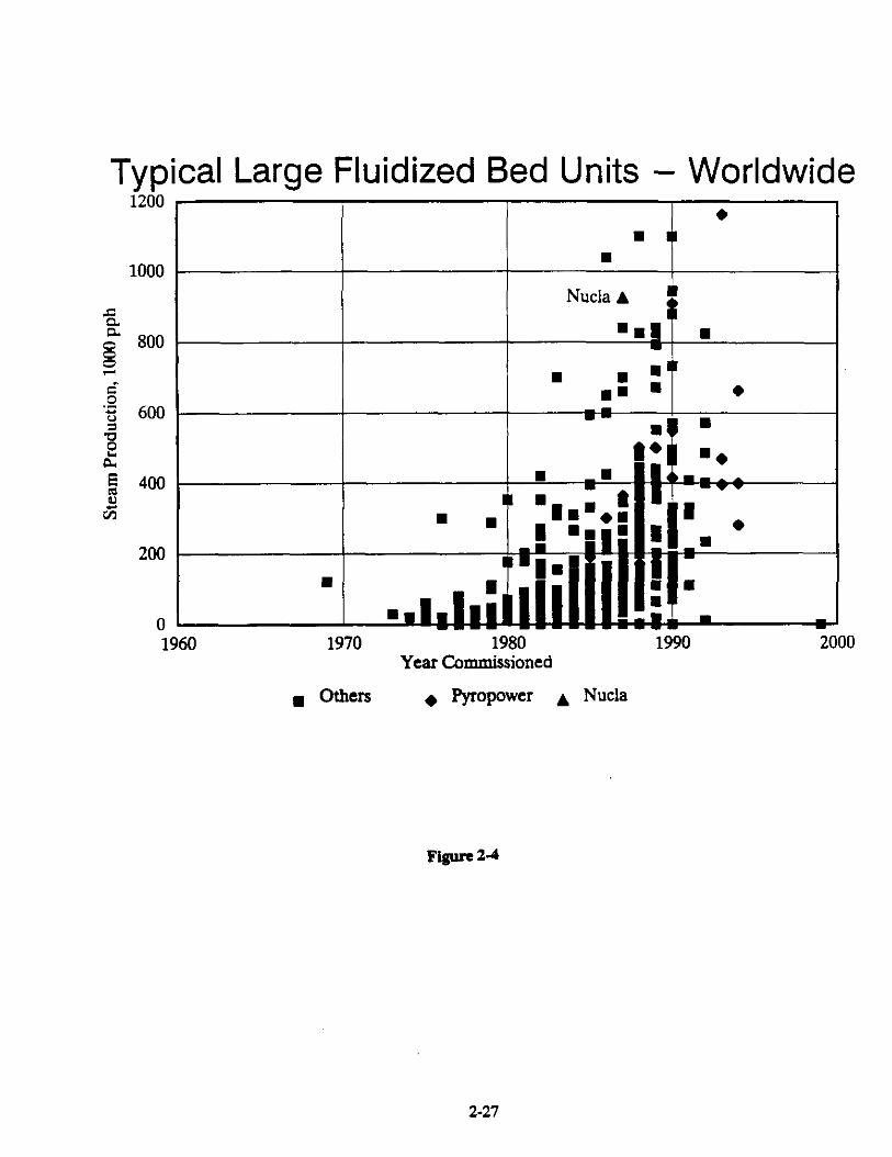
. The 200 MWe boiler size chosen is a reasonable extension of similar units that are presently operating, and hence should be available as a mature technology in a reasonable time period. A listing of fluid bed boilers installed by Pyropower and presently operating is shown in Figure 2-3, Pyropower FBC Units. If a curve depicting the average size of these units is drawn and extended into the future, the curve wiIl reach the general size area of 1,500,OOO lb/h, which is the size of the individual boilers proposed, well within the next decade. Figure 2-4, Fluid Bed Units, includes a fairly comprehensive list of free world FBC units, installed and operating, including the Pyropower units. The Pyropower units are generally in the conservative portion of the range of sixes, which reinforces the fact that when Pyropower units are designed, built and operated in the size considered, the technology should be well along the path to maturity.
. It is reasonable to conclude that a 200 MWe, or 1,500,OOO lb/h ACFB boiler will be commissioned by 1997-1999. Within 2 to 3 years after this, an operating base for this size unit will have been established, and a utility could be confident, that when an order is placed for one, the technological degree of risk associated with it has been minimixed, and unit availability can be expected to be similar to other mature technologies. If, however, the size of the boiler were enlarged to 300 MWe or greater, there’would be a higher degree of risk. With a higher risk, more time is required for mitigation. This difference could be anywhere from a few to many years depending on the demand for this type of equipment, and the perceived problems involved in the enlargement process. In the 1960’s and early ‘70’s, electric utilities were burned when PC boilers were enlarged beyond sixes that could be justified based on previous operating experience, and some large units were then rated at less than their intended capacity. The fluid bed boilers are a relatively new technology for electric utilities and it can be expected that progress to larger sixes will be done cautiously.
2-25
Pyropower Fluidized Bed Units 1200
l
1000
A Nucla 0
s 5 l
‘5 600 4 0 i? 6 l P, l
5 400 0 v - 2 l l cn l
l 4’ l
200
1980 1985 1990 Year Commissioned
l Pyropower A Nucla
Figure 2-3
2-26
Typical Large Fluidized Bed Units - Worldwide
s
E 800 z s ‘E 600 -I 3 k s 400 8 8 2 VI
200 ~ 8
0 1960 1970 1980
Year Commissioned
8 others + Pyropower A Nucla
Figure 2.4
2-27
. This technology should be capable of achieving successful commercialization at this size; the problems encountered to date appear to be solvable within a scale-up of the technology of 2 to 1 or less, as it is in this case.
. It is expected that a large portion of the utility industry will prefer a unit capable of generating more than 200 MWe (the size of the recommended boiler) for the majority of the expansion envisioned in the 1990’s and beyond. The economic trade-offs used to select the unit size will probably dictate a unit in the 300 to 600 MWe range. Extending the size of the circulating fluidized bed boiler beyond 200 MWe in the reasonably near future and considering it to be a mature unit is not as conservative as desired for this case. Hence, two 200 MWe boilers providing steam for a single 400 MWe turbine-generator is the most logical choice, given these parameters. Unit size (400 M~We) is in the predicted most desirable size range and each boiler is a reasonable extension of today’s technology. In addition, it not only provides enhanced availability at part load by allowing one boiler to be taken out of service without shutting the plant down, it also results in higher efficiencies at low loads by taking one boiler out of service and operating the remaining boiler near it’s most efficient operatingpoint.
. Present day control systems can be designed to successfully control two boilers and one turbine with reheat, thus providing an efficient coal-fired plant.(4)
The choice of 2-200 MWe boilers does not imply that 200 MWe is the largest ACFB boiler that will be built. In the near term, 250 to 300 MWe modules may be designed and built. Rather, 200 MWe fits several criteria, including a size near the maximum size expected to be built in the near term.
The balance of the plant will be designed for operating availabilities comparable to a commercial PC unit of similar capacity.
Even though the size increase from presently operating to future mature commercial plants considered here is not large, there are still some areas of concern that will have to be addressed.
. On the newer, larger units, there are questions about part load operation. For instance, how rapidly can load changes take place, and what part load points can be sustained for extended operation. One study done for a large Pyropower plant(5) assumed a load change rate of 5% per minute, which would be acceptable, if correct. However, only experience will confirm this and the capability to shed load without plant trip under upset conditions. Also, the steam conditions at lower load points need to be determined. These questions become even more important because the unit under consideration will be a reheat unit, which will tend to make sustaining full load steam temperatures more difficult at lower loads.
. There are many techniques for controlling steam temperatures on a large, utility type boiler. These techniques are generally applicable to a ACFB plant, and can be successfully applied using experience from the units now in operation. This can also be assumed for the steam temperature control at part load as long as the load ishot changing. However, during load changes, enough disruption may occur that the unit could be tripped. This will be especially true during rapid load changes, since the ACFB tends to respond to load change requirements more slowly than a PC unit. An additional problem that may occur on a plant
2-28
with two boilers and one steam turbine is one of mismatch of steam temperatures between boilers. During steady load operation, control will be relatively simple, but during load changes, the problems envisioned for ACFB units in general will be magnified by having two steam sources.
. One of the advantages in having two boilers on a power plant is that when one boiler is out of service, the other boiler can still produce steam so that the plant can operate at half load or slightly better. Also, if low load plant operation is desired, one boiler can be taken out of service and the plant efficiency wiIl not suffer as much. However, the plant should be capable of transfer from two boiler to one boiler operation and vice versa. If the steam temperatures sag too much at 50% plant output, it may be a problem to make the transfer. At the least, care will have to be taken to design the control system such that this transfer can be made with minimal effect on plant life.
The design of the commercial plant will be done with assumptions made where an area of concern cannot be addressed with a final conclusion.
2-29
3.0 REFERENCE PLANT DESIGN DESCIUFTION
The Reference Plant Design is based on the technology demonstrated at the Nucla Plant and is described in this section.
3.1 DESIGN BASIS
The plant design basis has a significant influence on equipment selection, plant construction and operation, and resulting capital and operating wsts. The following sections describe the basis which has been established for this plant.
3.1.1 P-&a Condiw
The plant site is assumed to be in the Ohio River Valley of western Pennsylvania/eastern Ohio/northern West Virginia. The site consists of approximately 300 usable acres (not including ash disposal) within 15 miles of a medium sized metropolitan area, with a well-established infrastructure capable of supporting the required construction work force. The area immediately surrounding the site has a mixture of agricultural and light industrial uses. The site is served by a river of adequate quantity for use as makeup cooling water with minimal pretreatment and for the receipt of cooling system blowdown discharges.
A railroad line suitable for unit wal trains passes within 2-l/2 miles of the site boundary. The site is served by a well-developed road network capable of carrying AASHTO H-20 S-16 loads and with overhead restriction of not less than 16 ft (Interstate Standard).
The site is on relatively flat land with a maximum difference in elevation within the site of about 30 ft. The topography of the area surrounding the site is rolling hills with elevations within 2000 yards not more than 300 feet above the site elevation.
The site is within Seismic Zone 1, as defined by the Uniform Building Code, and the ambient design conditions will be:
. Pressure 14.4 psia
. Dry bulb temperature 600F
. Dry bulb temperature range (-) 10 to (+) 110 ’ F
. Wet bulb temperature 52’ F
A sufficient number of well-trained construction laborers are available within a 50-mile radius of the site. Labor conditions are such that a “Project Work Agreement” can be obtained from labor organizations and contractors.
All commodities of bulk construction material are available locally and can be delivered within a reasonable period of time.
3-1
3.12 Fuel and Sorbent
Plant performance will be based on the Pittsburgh coal and Greer limestone compositions and data listed in Tables 3-l and 3-2. No. 2 fuel oil will be used for unit start-up.
3.13 CaoaciQ
The plant will consist of two circulating fluidized bed boiler modules that can operate individually to produce up to 50% plant load, or will operate in parallel to produce steam up to 100% plant load for one turbine generator that will produce approximately 400 MW net output. The boilers and other equipment in the steam producing systems have been sized based on flows, pressures and temperatures corresponding to the steam turbine valves-wide-open (VWO), 5% over pressure (OP) design point.
3.1.4 Plant Liic
The plant will utilize components suitable for a 30-year life, with provision for periodic maintenance and replacement of critical parts. Major components requiring periodic maintenance during the plant life will be identified and the cost for the work included in the plant economic analysis.
3.15 Plant Availability
The plant will be capable of achieving a 65percent levelized capacity factor while operating in a utility system.
Auxiliary systems that operate continuously and are essential for power generation shall be designed to have standby (backup) capability. Generally, the backup units are brought into service automatically. The backup capability may include fractional capacity equipment that can operate beyond the design point.
3.1.6 Mahwitv of Plant Technology
The plant design will be for a mature technology (i.e., the nth plant). First-of-a-kind considerations such as high design margins, excessive test instrumentation, etc., will not be included in the design.
3.1.7 Steam Conditions
A single reheat steam turbine will be used, with the following nominal steam conditions:
Plant performance is based on the nominal 2400 psig throttle steam pressure conditions (i.e., pressures, temperatures, and flow rates) with an assumed 2.5-m. Hg condenser back pressure. Plant design is based on the VWO, 5% OP conditions.
Condensing steam cycle calculations will account for pressure drops in the equipment ducts and piping. The following pressure drops through the steam system piping will be assumed for the heat balance if more accurate estimates cannot be made:
. Main steam: 5 percent
. Cold and hot reheat steam: 5 percent (reheater excluded)
Insulation and lagging will be provided on pressure vessels, piping, valves, and all other plant components that are potentially a significant heat-loss source to ambient and that require protection for personnel, The outside surface temperature will be limited to 145OF, with an ambient air temperature and velocity of lOOoF and 160 ft/min respectively. If higher temperatures are used, appropriate personnel protection, such as a surrounding cage, will be specified and included.
3.13 Preheating
A No. 2 oil-fired start-up burner(s) is provided as the primary means for unit preheat and start-up. Where required, additional preheat sources such as electric/steam trace heaters or steam coil air heaters are provided to prevent cold-end acid corrosion, to preheat refractory, etc. If required, an auxiliary boiler firing No. 2 fuel oil will be provided to meet preheat requirements.
3-4
3.1.10 Modes
The plant is designed for base-load operation with occasional turndown to 25% plant load. The normal operating load range is from 25 to 100%. Below 25% load, the plant is in a start-up or shutdown mode. The high-pressure steam turbine operates at constant pressure over the operating load range.
Heat and material balances were prepared for the plant for the 100% load condition. Control/load following, start-up, and shutdown procedures are established.
3.1.11 ~ontml Svstems
An integrated plant wide control and monitoring system (DCS) is provided. The DCS is a redundant micro-processor based, functionally distributed system. The control room consists of multiple video monitor (CRT) and keyboard units. The CRT/keyboard units are the primary interface between the generating process and operations personnel. Minimal dedicated control and monitoring instrumentation is provided to safely shut-down (trip) the unit on a loss of the DCS. The DCS incorporates plant monitoring and control functions for all the major plant equipment. Control of minor plant equipment is included where economically practical.
The following control functions are implemented in the DCS: boiler and combustion controls, burner management, and plant logic. The following monitoring functions, as a minimum, are incorporated: alarming, trending, historical storage and retrieval, sequence of events, logging, and performance calculations.
The design of the DCS complies with the applicable standards of ASME, IEEE, ISA, NEMA and NFPA.
The DCS is designed to provide a unit operating availability of 99.5%. Geographic distribution of portions of the DCS is implemented where a cost/benefit analysis identifies an installed cost saving while maintaining the design criteria and availability required above.
The plant equipment and the DCS are designed for automatic response to load changes from minimum load to 100%. Start-up and shut-down routines are implemented as supervised manual with operator selection of modular automation routines available.
3.1.12 Plant SeTices
The following services/support systems are available at the plant as a part of the balance-of-plant systems. any additional services required will be identified.
. c\uxiliarv Power Svstemq
7200-v system for motors above 3000 hp.
3-5
4160-v system for motors from 250 to 3000 hp,
480-v system for motors 0 to 250 hp and miscellaneous loads.
Emergency diesel generator (480 v) to supply loads required for safe and orderly plant shutdown. Instruments and controls and other loads requiring regulated ( 1 percent) 208/120 vat power are supplied from this source.
250 vdc system motors and, via static inverters, uninterruptible ac power for the integrated control and monitoring system, intercommunication.
125 vdc system for dc controls, emergency lighting, and critical tripping circuits including the plant shutdown system.
. Cooline Water
Cooling water (from the cooling towers) is available at between 30 and 50 psig, 90°F maximum temperature. The water is periodically chlorinated, and pH is maintained at 6.5 to 7.5. The cooling towers receive makeup water from the river.
Auxiliary cooling water, which uses demineralized water treated for corrosion control, at 60 to 80 psig and 10S°F, is available for small heat loads (e.g., control oil coolers). The pH is maintained at about 8.5.
. Comoressed Ait
Instrument air filtered and dried to -4O’F dewpoint at 80 to 100 psig and 1lO’F (maximum).
Service air at 80 to 100 psig and llO°F (maximum).
l LubeOil
Lube oil from the conditioning system, with particulate matter removed to 10 pm or lower.
. Hvdroeen and Carbon Dioxide
I-I2 and CO2 for generator cooling and purging from storage.
. Nitroeen
N2 for equipment blanketing against corrosion during shutdown and layup.
3-6
. Raw Water
Filtered river water. Additional water treatment wiIl be included for potable water, etc.
3.1.U Structures and Foundations
A structure or structures are provided to support and permit access to alI plant components requiring support to conform with the site criteria defined in Section 3.1.1. The structure(s) are enclosed if deemed necessary to conform with the environmental conditions.
Foundations are provided for the support structures, pumps, tanks, and other plant components. A soil-bearing load of 5000 lb/ft2 is used for foundation design.
3.1.14 &&t Recova
Sensible heat in solids streams discharged from the plant is recovered to the extent economically practical.
3.1.15 Q&s and Standards
Recognised design codes and standards that are commonly used for the design of commerciaI fossil-fuel-fired power plants are applied to the extent of ensuring that their requirements are met. Where the existing codes and standards cannot be applied to the design and fabrication of a component, the components will be designed using accepted industry standards. Some of the more important applicable codes and standards are listed in Table 3-3.
Table 3-3 TYPICAL DESIGN CODES AND STANDARDS
. ASME Boiler and Pressure Vessel Code: Section I, Power Boilers, Section VIII, Divisions 1 and 2, Unfired Pressure Vessels
. ASME/ANSI B31.1, Power Piping Codes and Addenda
. National Fire Protection Association (NFPA) Code, ( Volumes 1 through 16,1979, including Supplements A and B
. OSHA ReguIations, 29CFR1910
. Uniform Building Code
. ANSI A58.1, Building Code Requirements for Minimum Design Loads in Buildings and other Structures, 1979
3-7
3.2 HEAT AND MASS BALANCE
The steam power cycle is shown schematically in the 100 percent Heat and Mass Balance diagram, Figure 3-1. The diagram shows state points at each of the major components for the conventional plant. Overall performance is summarised in Table 3-4 which includes auxiliary power requirements.
The plant uses a 2400 psig/lOOO°F/lOOOOF single reheat steam power cycle. The high pressure turbine uses 2,867,038 lb/h steam at 2415 psia and 1OOO’F. The cold reheat flow is 2603,391 lb/h of steam at 531 psia and 617’F, which is reheated to 1OOO’F before entering the intermediate pressure turbine section.
Tandem high, intermediate, and low pressure turbines drive one 3600 rpm hydrogen-cooled generator. The low pressure turbines consist of two condensing turbine sections. They employ a single-pressure condenser operating at 2.5 HgA. For the low pressure turbines, the last stage bucket length is 30.0 inches, the pitch diameter is 85.0, and the annulus area per end is 55.6 square feet.
The feedwater tram consists of six closed feedwater heaters (four low pressure and two high pressure), and one open feedwater heater (deaerator). Extractions for feedwater heating, deaerating, and the boiler feed pump, are taken from all of the turbine cylinders.
The net plant output power, after plant auxiliary power requirements are deducted, is 400 MWe. The overall net plant (HHV) efficiency is 34.35 percent.
The major features of this plant include the following:
. boiler feed pumps are steam turbine driven
. turbine configuration is a 3600 rpm tandem compound
. plant has six stages of dosed feedwater heaters plus a deaerator
A 5% O.P., VW0 Heat and Mass Balance (Figure 3-2) was prepared, on which the design at the plant is based. The net power output increased by 8.8 percent with the efficiency increasing from 34.385 to 34.42 percent. Overall performance is summarized in Table 3-5 which includes auxiliary power requirements.
3-10
c
r
I 1 ,tnl I , -1 I I -
I t _. - ._. _. _. -. _ .- .-.-. -. -,
3:. $25
8 i
r
Table 3-5
PLANT PERFORMANCE SUMMARY - VWO, 5% O.P.
STEAM CYCLE Throttle Pressure, psig Throttle Temperature, OF Reheat Outlet Temperature, OF
2,521 1,000 1,ono
POWER SUMMARY, kWe 3600 rpm Generator GROSS POWER, kWe 476,448
Environmental standards applicable to the design of an electric utility power plant relate primarily to air, water, solid waste, and noise (Table 3-6). Both State and Federal regulations control emissions, effluents, and solid waste discharged from the plant. Additional environmental regulations may apply on a site-specific basis (National Environmental Policy Act, Endangered Species Act, National Historic Preservation Act, etc.) but will not be considered for this project.
Table 3-6 APPLICABLE ENVIRONMBNTAL REGULATIONS
Clean Air act as amended in 1990, including:
l New Source Performance Standards l National Ambient Air Quality Standards l Best Available Control Technology l Lowest Achievable Emission Rate
Federal Water PolUion Control Act (as amended by the Clean Water Act of 1977), including:
l Section 404 Dredge and Fill l National Pollution Discharge Elimination System l Best Available Technology Economically Achievable l Effluent Guidelines and Standards 4OCFR423
Resource Conservation and Recovery Act (RCRA)
OSHA Regulations 29CFR1910
State Regulations
l Air Quality Standards l Water Qua&y Discharge Standards l Solid Waste Disposal Standards
3-13
33.1 Air Oualitv Standards
The plant pollution emission requirements under New Source Performance Standards (NSPS) are:
. SO, : go-percent removal l Particulates: 0.03 lb/l@ Btu
. NO, : 0.6 lb/lo6 Btu l Visibility: 20-percent opacity
However, in most cases, Prevention of Significant Deterioration (PSD) Regulations will apply, requiring that Best Available Control Technology (BACT) be used. BAC’I is applied separately for each site, and results in different values for different sites. In general, the emission limits set by BACT will be significantly lower than NSPS limits. The following ranges will generally cover most cases:
. so, : 92 to 95%
. NO, : 0.2 to 0.45 lb/lo6 Btu
. Particulate: 0.015 to 0.03 lb/lo6 Btu
. Visibility: lo-20%
Air quality regulations concerning other compounds such as CO, CO2 and air toxics are being considered by federal authorities at the present time, and may have an effect on the design of plants in the time frame being considered here. However, details of the end results of these considerations are not clear at the present time and are not included in this report.
33.2 Water
Waste water, principally cooling tower blowdown, boiler blowdown, ash transport water, and process condensate or purge water, will be discharged following treatment to comply with the Environmental Protections Agency Effluent Guidelines and Standards (Title 40CFR).
333 Solid Waste Disoosal
Spent sorbent, ash, air-pollutant emission control waste, and sludge produced from water treatment will be disposed of according to the nonhazardous waste disposal guidelines of Sections 1008 and 4004 of the Resource Conservation and Recovery Act (RCRA), and applicable state standards, appropriate for the actual plants’ location.
Several programs are presently underway to characterize and classify solid wastes from CFB plants, to determine if the wastes can be utilized profitably in some manner. If these prove
3-14
attractive, solid waste disposal requirements could be reduced substantially, increasing the attractiveness of the CFB option.
33.4 &i&e
In-plant equipment will be designed to meet the noise exposure regulations of the Occupational Safety and Health Administration (OSHA). Noise levels from major noise sources (e.g., fans, motors, gas turbines, valves, pumps, and piping) will not exceed 95 dBA at 3 ft. Outdoor noise criteria for on-site sources of noise will be an integrated equivalent level (Leq) of 55 dBA at the property boundary. The minimum distance to the property line will be assumed to be I000 ft.
3-15
3.4 DESCRIFTION OF STEAM GENERATION SYSTEMS
The following sections contain descriptions of the steam generation systems in the plant. The boiler description was obtained from the vendor, Pyropower. The balance of the steam generation systems are conventional for this size plant.
3.4.1 S m teat Eaulomen
The 400 MWe circulating fluidized bed reference plant consists of two 200 MWe Byropower combustors, coal and limestone feed systems, boiler ancillary equipment and one GE turbine generator. This section includes descriptions of:
l Pyropower boilers
. Coal and limestone feed systems
. Boiler ancillary equipment
. Ash discharge system
A description of the equipment is included in Appendix A, Major Equipment List. Figures 3-3 and 3-4 illustrate a plan view and cross section of the boiler, respectively.
3.4.1.1 Operation Description
Pvromnver Boiler
The Pyropower boilers are designed for a flow of 1,580,454 Ibs. of steam per hour at 2660 psig and 1OOO’F at the superheater outlet. Conditions at the reheat outlet are a flow of 1,430,404 Ibs. of steam per hour at 543 psig and 1OOO’F.
The major components of Pyropower’s patented CFB boiler system are the combustion chamber, the hot cyclone, the non-mechanical loopseal and the convection section as shown in Figure 3-5, Air and Gas Flow Schematic. In the combustion chamber the bed material, with the fuel, is fluidized with primary air which turbulently transports the solids up the full height of the combustion chamber. Combustion of the fuel takes place as it rises and heat is transferred to the membrane water-wall tubing that forms the walls of the combustion chamber, evaporative wingwall surfaces and radiant superheat surfaces. The hot combustion gases with the entrained solids exit at the top of the combustion chamber into the hot cyclone. The cyclone separates the solids from the combustion gases and returns the solids, including any unburned solid fuel, through a non-mechanical loopseal to the,combustion chamber where they mix with incoming fresh fuel. The long solids residence time at combustion temperature and the retention and continuous recirculation of the solids ensure high combustion efficiencies and provide an ideal system for the mixture of fine limestone with the fuel for efficient SO2 retention as a solid. Coal is fed into the lower combustion chamber and the loopseals.
3-16
I
t % z ;
I
: i : IO
I -0 N
II
3
6 I
-0 d
II
0
I=\ ILJLr--lII II II II
c I
-c Lr II I
t I
3-19
As sulfur in the form of SO2 is released from the combusted coal, it reacts with calcined limestone to produce CaS04. The sulfation reaction requires that there is always an excess amount of limestone present. Limestone is fed directly to the bed in order to maintain a pre-determined ratio of calcium-in-the-limestone to sulfur-in-the-coal which for this boiler is 2.5 to 1. This ratio ensures an SO2 emission rate of less than 0.371 lb/106Btu (92% reduction).
The lower section of the combustion chamber includes a water cooled air distribution grid and a bottom ash removal system. Primary air is supplied through the lower windbox to the distribution grid providing fluidization air flow. Secondary air entering above the bed ensures solids circulation, provides staged combustion for NO, reduction and supplies air for continuous fines combustion in the upper part of the combustion chamber.
Flue gas and some particulate matter leave the hot cyclone collector and pass through the convection section which contains primary and final superheat, reheat and economizer banks, plus a tubular air preheater. The flue gas then enters a reverse air baghouse where particulate matter is removed in compliance with environmental regulations. Clean flue gas is discharged to the stack via the induced-draft fan.
Feedwater enters the economixer and flows counter to the flue gas, picking up heat before entering the drum. Water flows from the drum to the lower combustion chamber headers via downcomers and supply pipes. The combustion chamber is arranged for complete natural circulation. As the steam/water mixture in the waterwalls absorbs heat from the combustion flue gases it rises up the water wall tubes, is collected in the upper combustor headers and is transferred to the drum via riser tubes. The density difference between the water and the steam/water mixture creates a natural pumping action. The steam/water mixture is separated in the drum.
Dry saturated steam leaves the top of the drum and is delivered to the convection cage walls, then to the superheater inlet header. Heat from the flue gases is transferred to the steam in the superheater tube bundles. The superheater bundles are arranged in multiple stages (primary, intermediate and final) with attemperation between each stage. The superheated steam exits the outlet header of the final superheater and enters the main steam header for delivery to the turbine generator.
Exhaust steam from the high pressure turbine enters the reheat inlet header, passes through the reheat tube bundles absorbing heat from the flue gas and flows to the reheat outlet headers for transmission to the intermediate pressure turbine.
The design used for the Reference Plant is different than that used for Colorado Ute’s Nucla Plant in several significant areas. The following is a fist of the more important changes and some of the reasons for the changes. In general, changes have been made to improve reliability where operation has shown the need for modification, or to address performance in terms of carbon bumup efficiency, NO, production, or limestone Ca utilixation.
3-20
1.
2.
3.
4.
5.
6.
7.
8.
9.
10.
11.
12.
13.
14.
15.
16.
Double loop seals will be used to allow recirculating solids to re-enter the combustor in two distinct flow streams for better distribution.
16 vs. 8 limestone feed points to improve distribution of calcined limestone and contact with so2.
In-combustor wingwahs have been added to provide additional evaporative and superheat duty.
An in-combustor omega superheat surface is designed to provide a flat surface parallel to the upward flowing gas in the combustor, thus minimiring erosion.
A bottom drain classifier is used instead of a side dram for ash removal because it is more economical.
A tlyash reinjection system was added to optimixe limestone utilixation and carbon burnout.
Refractory brick is used in the cyclone instead of castable or gunnite to minimize erosion, improving refractory life.
The cyclone configuration was changed to lessen reentrainment and maximise gas residence time in the cyclone.
A single piece vortex finder was added to the cyclone to prevent shortcutting and enhance particulate capture.
The refractory/watenvaU interface design was changed to eliminate ash eddying and decrease erosion potential.
Pigtail nozzles are used instead of bubblecaps to reduce backsifting of ash into the windbox, to improve maintainability of the nozzle system by allowing a simplified method of cleaning the nozzles from the windbox area, to eliminate the potential of erosion of the nozzles, and to enhance the migration of the coarser materials to the ash removal ports.
A change in the air supply source was made to allow initial variation in the primary/secondary air split to provide optimum heat transfer;performance, and emission characteristics for the wmbustor system.
Belt conveyors for tire1 are generally being used instead of drag chains based upon superior performance relative to maintenance requirements.
Splitter screws are used in the fuel feed system to improve flow of fuel to feed ports.
Additional instrumentation was added to the control systems to provide more time/function graphs and emission data.
An ammonia or urea DeNOx system could be used for NO, control, if required, but was not included in the Reference Plant design.
3-21
17. A single combustion chamber was designed instead of two to alleviate flow distribution problems.
18. Duct burners were eliminated; ah start-up burners are now located in the lower combustor area.
19. The steam driven auxiliary feed pump was changed to a motor drive for economic reasons.
20. The rotary feed valve/pressurisation of the feed system was eliminated to improve reliability.
21. The “wrap-around” combustor superheat surface was eliminated and the backpass superheat hanger design was changed.
Because of the increasing international concern about the greenhouse effect, the discharge of N20 from combustion sources has gained recent attention. Fluidized beds are known to emit larger amounts of N20 than PC boilers per unit size, primarily because of the lower combustion temperature. Reduction of N20 might be accomplished in three ways, all of which have offsettmg drawbacks or penalties:
. Increase temperature in the combustion chamber. This will lead to higher NQ emissions and an increase in limestone requirements.
. Decrease excess air. This will normally lead to decreased combustion efficiency.
. Add a gas-tired post-combustion system following the cyclone. ‘fko stage combustion requires a more expensive fuel for the second stage, or a more expensive fuel delivery system. TWO stage combustion is also difficult to accomplish in a CFB type boiler.
The control or reduction of N20 has not been addressed in this design because N20 levels are presently unregulated.
3.4.12 Combustor Design
The combustor is designed as a totally water-cooled chamber using only natural circulation. The tubes are designed of carbon steel using 2-l/2 inch tubes on 3 inch centers. The lower portion of the combustor waterwalls from the grate to a level just above the secondary air ports are refractory-lined with a high alumina’refractoty to protect the waterwalls from abrasion and the reducing atmosphere present in this area. The refractory is applied as a rammed refractory at a thickness of about 2 inches.
The interface where the refractory ends and the bare waterwalls begin is designed using a proprietary feature that eliminates direct impingement of the bed material cascading down the walls on the refractory interface. Previous experience has shown that any type of discontinuity at this point (feathering, shelves, etc.) results in gradual erosion of the watenvalls at this point caused by turbulent eddies that are formed. Hardfacing of the water-walls above this interface point has
3-22
been reasonably effective in minimixing this erosion, but the new proprietary design eliminates this erosion potential due to ash eddying.
A second proprietary feature is included near the bottom of the combustor chamber just above the fluidixing grid. This feature prevents direct impingement of the ash cascading down the refractory-covered walls onto the fluidixing grid, and assists in redistributing the ash more evenly across the floor of the combustor.
The windbox is designed as a carbon steel attachment to the bottom of the combustor. The windbox is generally not refractory lined except in instances where windbox startup burners are required for startup. It is not anticipated that windbox burners will be required for this application.
Due to the size of this application, all of the required evaporative duty cannot be provided by the combustor waterwalls alone. The remaining evaporative duty is provided bywingwah panels located on the front wall of the combustor. (Note that some of the wingwall panels are evaporative panels, while the remainder are superheat panels, the design is essentially the same. The superheat panels are discussed below.) Each wing wall panel consists of a series of parallel watertubes that enter horizontally into the combustor chamber through the front wall approximately half way up the wmbustor wall, and then turn upward, leaving the wmbustor chamber through the roof. The horizontal portion of the tubes are, therefore, stacked in a vertical direction, while the vertical portion of the tubes run parallel to the upward gas flow.
The horizontal portion of each panel, and several feet of the panel in the vertical direction, are refractory lined to protect against erosion from the solids cascading down the walls, and, to a lesser extent, against erosion from solids travelling upward with the gas stream. This style of wingwall panel has been operating success5tlly in several CFB applications for up to 6 years.
Special provisions are included in the design to seal the wingwalls at both penetration points in the combustor (side wall and roof), and to provide for expansion differentials that may be present.
The upper portion of the wmbustor chamber is provided with openings which allow the 5ue gas and entrained particles to enter the cyclones.
A proprietary primary air 5uidizing grid is provided at the 5oor of the wmbustor. The grid is sloped approximately 2 degrees to facilitate ash removal. The bottom of the grid system (portion facing the windbox) is a water-cooled membrane which is an extension of the waterwalls. The proprietary noxxles are welded to the webs of this membrane surface, and terminate several inches above the membrane surface in a single air outlet for each nozzle. Refractory is then placed over the membrane surface such that nozzle termination orifice is 5ush with the top of the refractory, thus providing a 5at floor in the combustor to facilitate internal maintenance in the wmbustor to enhance the migration of coarser material to the bed drain system (since there are no nozzle projections to impede this movement) and to provide erosion protection for the nozzles. The nozzles are also designed to minimize ash backsifting into the windbox.
3-23
The combustor normally operates with a differential pressure drop from the top of the grid to the top of the combustor of about 25 to 30 inches of water depending on the fuel characteristics. Typical slumped bed height is 2 to 4 feet.
3.4.13 Cyclone Design
This 200 MWe unit is provided with 3 cyclones arranged on the rear wall of the combustor (between the combustor and backpass). Each cyclone is approximately 24 feet in diameter, and incorporates the use of metal vortex finders projecting downward from the cyclone outlet into the scroll area. The vortex finders enhance the capture of particulate by avoiding short-circuiting of the incoming dust directly to the outlet. At a capture efficiency of over 99%, and a particulate cut size of approximately 80 microns, sufficient ash is normally retained in the circulating loop to avoid the addition of supplemental sand or limestone to maintain adequate solids in the system. Supplemental solids addition would only be anticipated for extremely low ash, low sulfirr fuels.
The cyclones are designed to minim&e reentrainment from the cone of the cyclone, and to maximise residence time of the gases in the cyclone. Areas in the cyclone that are subject to high potential abrasion are provided with either hardfaced brick or castable refractory wntaining high alumina wntent and designed to resist alkali attack. The barrel of the cyclone is primarily brick and the wne is designed entirely using brick. Other portions of the cyclone, loop seal, and inlet/outlet ductwork are provided with refractory appropriate to the environment; brick, castable, rammed, and gunned refractory are provided as the environment requires.
The above refractory is the portion in direct wntact with the 5ue gas and/or ash. Between this refractory and the metal shell of the cyclone, insulating refractory is applied such that the outside metal temperature of the cyclone is between 160 and 180 degrees F. Protection for personnel in areas where maintenance or access is required are provided with screening to prevent accidental skin wntact with the shell.
Bed material separated in the cyclones is directed through the loop seals back to the wmbustor. For applications of this size it is wmmon to provide a split loop seal such that the recirculating solids 50~ is split in the loop seal and reenters the wmbustor in two distinct flow streams. The design of a typical split loop seal is shown in Figure 3-6. Fuel feed to the loop seals is provided to each returning solids 50~ stream; therefore, for this 200 MWe design, a total of six fuel feed points are provided on this rear face of the combustor. Additional front wall fuel feed (discussed later) is also provided.
3.4.1.4 Air Distribution
Air for combustion is provided in two different regions of the wmbustor. Approximately SO-65% of the combustion air is provided through the windbox/fluidixing grate as primary air. This air is normally provided by a centrifugal fan complete with inlet silencer and inlet vanes/dampers for flow control. The number of primary air fans is determined by the size of the application and the need for fan redundancy. For this application two primary air fans with outlet shutoff dampers are supplied to allow isolation of one of the fans for maintenance.
3-24
PYROFLOW CIRCULATING FLUIDIZED BED BOILER
SPLITLOOPSEAL
Figwe 3-6
The remainder of the combustion air is supplied by two secondary air fans, which are also centrifugal fans complete with silencers and 50~ control inlet vanes/dampers. The number of these fans is similar in principle to the primary air fans. Secondary air is introduced into the combustor above the grate. The system is designed to allow variation in the primary/secondary air split to provide optimum heat transfer, performance, and emission characteristics for the combustor system.
The secondary air fan system also provides air for other 5uidization and sealing ah functions. The complete secondary air system design is shown schematically in Figure 3-7.
A small amount of air is also introduced to the combustor through the loop seal as 5uidizing air. The loop seal air is supplied by blowers, and is introduced into the loop seal at proprietary locations in the loop seal and inlet/outlet ducts of the loop seal to assure complete 5uidization of the returning solids 50~. It is typical to provide one 5uidization blower for each loop seal for an application of this size. As with the secondary air system, the high pressure blowers provide 5uidiig air to other areas of the CFB system. Figure 3-8 shows schematically the high pressure air system design.
Fan margins are based upon the maximum air flow requirements consistent with the worst case fuel. To this calculated flow, an additional 20% is added in establishing the test block condition of the fans. From a pressure standpoint, the test block design is typically 30% higher than the calculated pressure drop of the system from the fan inlet to the top of the wmbustor (note that the balanced draft point of the CFB is at the inlet to the cyclones).
The ID fans will be of the backward curved design, with fan margins similar to the combustion air fans. Variable speed drives will be used to control fan capacity, i.e.., to maintain the balanced draft point in the wmbustor. The particular fan control method selected for this application will allow better control during part load operation. A base loaded plant could use inlet vane control.
3.4.15 Superheat System
The superheat surface is located in the backpass and in the combustor proper. The 50~ path of the steam is shown schematically in Figure 3-9, and is described in more detail below:
. From the drum, the steam is directed to the backpass walls and roof.
. From the backpass walls and roof, the steam is directed to the primary superheat section located in the combustor. This primary superheater is provided using Fyropower’s patented OmegaTM surface, which is designed to provide a 5at surface parallel to the upward flowing gas in the combustor. The OmegaTM surface spans the width (front wall to rear wall) of the combustor chamber. In addition, the leading tube (lowest tube in the bundle) is specially designed to provide minimum metal temperatures for further
pu rotection against erosion that
might accelerate due to high metal temperatures. The Omega type of surface has been in operation at several facilities for up to 5 years.
3-26
t
-l
HIGH PRESSURE AIR SYSTEM
I
BEARING Stl IGNITOR _ _.._ . GUN PURGE AIR
~:Aobe 1 I- HPBLOWER
PIANT AIR
Figure 3-8
3-28
a E In
s-
E (0
L f
. From the primary OmegaTM superheat section to the intermediate wingwall superheat section located in the upper portion of the combustor chamber.
. From the intermediate superheat section in the combustor, the steam 50~s to the final superheat section located as the first heat absorption section in the backpass. From here the steam 50~s to the turbine.
Steam attemperation is provided by a desuperheat station located between the primary and intermediate superheat sections, and between the intermediate and final superheat sections. The desuperheaters are of the venturi/spray type.
3.4.1.6 Reheat System
Both the primary and final reheat sections are located in the backpass of the CFB following the final superheat surface. The design of the reheat control system is shown in Figure 3-10. A specially designed patented reheat temperature control system using conventional bypass valves, selected to provide optimum control characteristics, is used to divert the 50~ based on reheat steam outlet temperature requirements.
This reheater design minimixes pressure drop by locating both of the reheat surfaces in one location (rather than splitting the surface in hvo different locations in the CFB), and allows startup of the CFB up to 30% of MCR without the need for reheat 50~ through the reheater, since backpass temperatures are below acceptable metal temperatures. It also avoids the need for backpass gas 50~ biasing dampers wmmon in other designs. Reheat metal selection is based on standard industry design criteria.
3.4.1.7 Economizer
The economiser is a bare tube, in line, horizontal serpentine type heat exchanger, arranged in multiple banks. Extended surface economisers may be provided when appropriate.
3.4.1.8 Air Heater
The air heater is a tubular air heater designed with gas over the tubes and air through the tubes. For the low outlet gas temperatures required for this application, the airheater would be provided in a multiple pass design, and both the primary and secondary air would be directed through the airheater. The various banks of the airheater would be provided with ample rotary sootblowers to maintain surface cleanliness.
Because a high differential pressure must be maintained for, the circulating 5uidized bed, regeneration air heaters are not a good choice for this service, since seal leakage would be excessive. In certain applications, where space constraints in particular are of concern, a heat pipe air heater may be employed. These are relatively new to the industry, and although there are some specific advantages to using them, the Reference Plant employs the more conventional tubular air heater. The selection of either the tubular or heat pipe configuration is site and
3-30
FEHEATERARRANGEMENT
PYROFLOW CIRCULATING FLUIDIZED BED BOILER
REHEAT DESIGN
-MAN STEAM
- HOT RH STEAM
Figure3-10
3-31
configuration dependent.
3.4.1.9 Bottom Ash Removal/Cooling System
It is anticipated that, for this application based on the 9.94 percent ash in the fuel, approximately 30% of the ash will be withdrawn as bottom ash, with the remainder leaving as flyash. The bottom ash system is designed to accommodate 100 percent of the total ash production.
The bottom ash may be removed in one of two designs, either using side ash coolers, or bottom ash coolers. Since there are no space constraints in the conceptual design, bottom ash withdrawal was chosen.
For this design, the ash is withdrawn downward through ports located in the floor of the combustor. The ash passes down through pipes which are located in the windbox. From there the ash enters conventional water-cooled screws, which cool the ash from 1600 degrees F to 450-500 degrees F. A total of six withdrawal points would be anticipated for this application.
The water-cooled screws are designed to use either cooling water (of boiler quality) or condensate. ‘lko separate cooling streams are provided in each screw; one stream cools the internal screw mechanism and the other cools the trough.
3.4.1.10 Fuel Feed System
Fuel is introduced into the combustor through both the loop seals and through the front wall. Based on three cyclones, each cyclone being designed with a split loop seaI, the loop seal feed system provides a total of six individual feed points to the rear wall of the combustor. Fuel is directed from the fuel transfer system to six vertical feed systems, one located above each loop seal return leg. Each vertical feed system consists of an isolation valve, expansion joint, vertical feed leg, and appropriate fluidizing system to maintain constant fuel feed.
The transfer system to provide fuel to the loop seals consists of a series of gravimetric feeders and belt conveyors. The design of the belt conveyors is proprietary, but it should be noted that belt conveyors have been selected in lieu of drag chain conveyors based upon superior performance of the belt conveyors relative to maintenance requirements.
The front wall feed consists of a gravity feed system operating under pressure. The design of a typical front wall feed system is shown in Figure 3-11. Fuel is directed from the silos through a vertical drop leg (for pressure isolation) complete with isolation valve and into two pressurized gravimetric feeders. From each gravimetric feeder, the fuel is split into two streams, each stream then entering the combustor by gravity. Thus, a total of four front wall feed points is provided. The design of the front wall feed ports to provide smooth flow of fuel into the wmbustor is a proprietary design.
3-32
FRONT WALL FUEL FEED SYSTEM
Gi3AVlMETRlC FEEDER
TWO-WAY’SPLITTER SCREW
ISOLATION VALVE
Figure 3-11
COMBUSTOR
3-33
Coal sizing and surface moisture content are critical to successful operation of the fuel feed system. Required coal sizing is dependent on the characteristics of the fuel. Top size may vary from l/4 to l/2 inch. Allowable coal moisture content is also fuel dependent; the smaller the required coal particle size, the lower the allowable moisture content of the fuel to provide good flowability of the fuel. Typically, surface moisture contents below 10% are desirable.
3.4.1.11 Limestone Feed System
The limestone is fed into the wmbustor pneumatically. Limestone sizing is critical to achieving optimum calcium-to-sulfur molar ratios. Ideal limestone sizing would be 100% less than 1000 microns, and a mean limestone size of 150 microns. Moisture content must be maintained less than 1% to provide for acceptable flowability and transport.
Limestone from the day silos is metered using either a gravimetric or volumetric belt feeder. From the metering system, the limestone is directed through rotary valves to the pressurizing blower exit pipe. A total of four limestone blowers are provided, each blower providing limestone to four individual injection points on the wmbustor. Thus, the limestone flow from each blower would be split twice to provide the four injection point flows, resulting in a total of sixteen combustor injection points.
The limestone is pneumatically transported and injected into the combustor chamber through secondary air ports. The limestone injection pipe is located concentrically within the secondary air injection pipe at the point of injection. Six injection points are provided on both the front and rear walls, and two injection points are provided on each of the side wags.
3.4.1.12 Startup Burner System
A startup burner system using No. 2 oil is provided to heat the bed material to the required ignition temperature of the coal. The burners are located several feet above the grid plate, and are typically designed to provide a total heat input of approximately 30 percent MCR For this application, a total of 10 to 12 burners is required to provide the total heat input and to distribute the heat properly within the combustion chamber.
Natural gas, if it is available, can also be used for startup fuel. Economics, based on geographical location should be used to make the choice.
Although X6 fuel oil has been used as a start-up fuel in many plants, there has been a reluctance to use it where baghouses are used for flue gas particulate clean-up, because of actual or perceived problems involving the blinding of the bags with oil soot. Pyropower claims that #6 fuel oil is now acceptable in their units, since they have found no problems with the use of #6 oil in their start-up burners, and do not require a baghouse bypass with the use of this oil.
3-34
3.4.1.U Flyash Reinjection
To optimize limestone utilization and carbon burnout, a flyash reinjection system is provided.
Ash reinjection is accomplished by direct reinjection of the flyash from the ash silo discharge. The design of a typical reinjection system is shown schematically in Figure 3.12. Ash from the silo is discharged into a lock hopper system, from which it is reinjected back into the CFB combustion chamber through the use of a dense phase pneumatic system. the quantity of ash reinjected will vary with the type of fuel being burned, but generally ranges from 50% to 100% of the quantity of ash that would leave the air heater ifreinjection were not being employed.
3.4.1.14 Sootblower System
Rotary and/or retractable sootblowers are provided for all convection pass superheat, reheat, economizer, and akheater surfaces. The sootblowers are located between tube banks, and are designed to provide complete cleaning coverage of all surfaces. Experience with CFB’s has confirmed that surface cleaning is generally required at most once per shift due to the nonadhesive characteristics of CFB dust.
3.4.1.15 Particulate collection
For this larger application, the decision regarding the use of pulsejet baghouse versus reverse air is primarily one of economics. Either system will meet the particulate emission levels specified. The use of electrostatic precipitators is not recommended due to the lack of operating experience on a wide range of fuels. The excellent CFB experience with baghouses to date makes the baghouse the system of choice at the present time.
At the 200 MWe CFB size either a pulse jet baghouse or reverse air baghouse could be used. Because the pulse jet would be designed at an air-to-cloth ratio of 4/l and the reverse air would have a ratio of 2/l, the pulse jet would be more economical. Typically the capital cost of the reverse air bag collector would be approximately 20% greater. However, the use of pulse jets in utility applications is not yet widely accepted so a reverse air baghouse has been selected for this conceptual design. The 2/l ratio is designed with hvo compartments out of service.
Flue gases from the boiler are conveyed through an inlet duct to the integral inlet plenum. The gases enter each hopper through a connecting elbow. Heavy particles drop directly into the hoppers and fine particles are conveyed upwards and are deposited on the inside of the filter bags. The bags are 12 inch diameter and 35 ft. long, and are constructed of fiberglass with a special acid resistant polymer finish which helps resist abrasion and lubricates the fabric for flexing purposes.
The clean gas passes through the fabric and exits the collector into the distribution plenum. The I.D. fan draws the clean gas from the outlet plenum and discharges it to the stack.
3.35
I a
a
3-36
The particles collected on the inside of the bags are dislodged by a reverse air cleaning system. The reverse air fan pulls clean gas from the outlet plenum and redistributes it into a selected compartment. When this clean gas enters the compartment, the filter bags collapse, dislodging the particles into the hoppers. The dirty reverse gases flow into the inlet plenum to be redistributed for filtering to the remaining on-line compartments. The cleaning sequence is controlled by differential pressure transmitter override. Each reverse air fan has an outlet louver control damper and a buttetily isolation damper.
The baghouse has inlet butterfly 5ow control dampers and outlet poppet dampers. There is also one bypass popper damper per baghouse which will open during a power failure or high temperature situation. Specific baghouse criteria are given in Table 3-7.
Table 3-7 BAGHOUSE DESIGN
.
.
. l
.
.
l
.
.
.
.
.
Inlet loading Outlet loading Pressure drop No. of compartments Quantity of bags per compartment Total No. of bags Overall A/C ratio A/C ratio net (one module off-line) A/C ratio act. (two modules off-line) Hopper capacity Overall dimensions
Reverse air power consumption
7.50 gr/acf 0.014 gr/acf
10 in of water 10
486 4860 1:6 1:95 22
97,ooo fG 83 x 80 x 138 feet
311 kW
3.42 CMI
The function of the coal handling system is to provide the equipment required for unloadmg, conveying, preparing, and storing the coal delivered to the plant. The scope of the system is from the coal receiving hoppers up to the boiler fuel inlet. A schematic diagram of the system is shown on the Coal Handling Flow Diagram, Figure 3-13.
3.42.1 Operation Description
The 6 x 0 inch bituminous coal will be delivered to the site by unit trams of lOO-ton rail cars. The choice of delivery system is site-dependent and may involve other means, such as trucks or barges. For this study, unit trains were selected as the most appropriate. Each unit train consists of 100, loo-ton rail cars. The unloading will be done by a rotary car dumper with a hydraulic car positioner. The rotary car dumper wig unload the coal to four receiving hoppers. Coal from each hopper is fed by a vibratory feeder onto a belt conveyor. The 6 x 0 inch coal is conveyed into a transfer building where a sample of coal is taken from each consignment by a coal sampling system. The main stream.of coal feeds onto the coal stacker conveyor.
3-37
,
:
The coal is fed into a traversing, double-wing stacker. The coal can be diverted to either the active pile boom conveyor or the dead pile boom conveyor. Each fixed boom conveyor has luffing capabilities for discharging the coal into a longitudinal pile. The double-wing stacker traverses on a track between the active and dead coal storage piles. Each coal storage pile is lined and provided with a runoff treatment system.
The dead pile boom conveyor discharges the coal onto the dead coal storage pile where a bulldozer moves and compacts the coal. The dead storage area will have an emerg-ncy reclaim hopper with a vibratory feeder feeding a belt conveyor. The conveyor discharges the reclaimed coal into the crusher building’s, surge bin.
The active pile boom conveyor discharges the coal onto the active coal storage pile and is reclaimed via three reclaim hoppers. The coal is then discharged onto a belt conveyor.
The coal is conveyed from the reclaim hoppers to the crusher building and is fed into a two-compartment surge bin, provided with a vent filter to reduce dust emissions. Each compartment of the surge bin supplies coal to a full size vibratory feeder. At the inlet of each primary crusher, a bypass 5op gate allows wal to be fed to either the primary crusher, or to a crusher by-pass when presided coal is being used. The primary crusher is a ring granulator type crusher while the secondary reduction of the coal is performed by an impactor type crusher.
Coal taken from the crusher discharge, is sampled by a two-strand, swing-hammer type sampling system before entering the boiler building.
Conveyors then feed the sized and sampled coal to either of the tripper conveyors. Each tripper discharges coal into a coal bunker for storage. The coal bunkers have two separate compartments, each with 16-hour total storage capacity. Conveyors are sized to fill the 16 hour bunkers in leas than 6 hours while the plant is operating at full load. The fuel is discharged into the boiler via gravimetric feeders.
3.422 Technical Requirements and De&n Baais
1. Coal Bum Rate
. Maximum Coal Bum Rate = 347,098 lb/h = 174 tph (based on two boilers operating at 5 percent OP, VW0 continuously)
. Average Coal Burn Rate = 250,000 lb/h = 125 tph (based on Maximum Coal Bum Rate multiplied by an assumed capacity factor)
3-39
2. Coal Delivered to the Plant by Unit Trams
l Three Unit Trams Per Week at Maximum Burn Rate Two Unit trains Per Week at Average Bum Rate
l Each Unit Tram Shag Have 10,000 Tons (loo-Ton Cars) Capacity
l Unloading Rate = 900 tph
l Total Unloading Time Per Unit Train = 13 hours
l Conveying Rate to Storage Piles = 900 tph
l Reclaim Rate = 643 tph
3. Storage Piles with Liners, Run-off Collection, and Treatment Systems:
l Active Storage = 9,000 tons (72 hours)
l Dead Storage = 270,000 tons (90 days)
System design re5ects the wncem for maintenance of the coal handling equipment in that redundant equipment is recommended in critical areas. Reclaiming and conveying belts, crushers, and bunker loading equipment fall into this category.
Access platforms and catwalks are provided to permit the periodic greasing, lubrication, and observation of all rotating or moving equipment.
Conveyors have a main access aisle either on one side or, in the case of two conveyors, between them with grease fittings directed toward this aisle.
On conveyor bridges or in tunnels, small access platforms or aisles on the outboard side give access to idlers for replacement. Monorails serve the conveyor head shafts and their accompanying drive assembly (gear and motor), permitting the removal of heavy pieces to grade.
The crusher building has monorails serving each crusher for rotor, motor, and drive assembly maintenance. For installations with a rotary car dumper, monorails serve the hydraulic pumps that operate the car positioner. A maintenance aisle adjacent to the pumps and their monorail system supports forklift truck traffic.
A hatch, strategically located in the car dumper, allows access to the lowest level in that structure. Equipment below the hoppers is winched or skidded into the hatch area, then hoisted to the surface with a “cherry picker” or truck crane.
3-40
3.43 Limestone Handline Svstem
The function of the hrnestone handling system is to provide the equipment required for conveying, preparing, and storing the limestone delivered to the plant. The scope of the system is from the receiving hopper up to the boiler limestone inlet. A schematic diagram of the limestone 50~ is shown on the Limestone Handling Flow Diagram, Figure 3-14.
3.43.1 Operation Description
Limestone will be delivered to the plant by 2S-ton trucks.
The limestone is unloaded into a receiving hopper. The limestone in the receiving hopper is then fed onto a belt conveyor via a vibrating feeder and then fed onto a tripper conveyor. The tripper conveyor feeds the material to a tripper, which distributes the limestone within the “An-frame storage building. The limestone is reclaimed within the “An-frame building by a portal scraper reclaimer. The portal scraper reclaimer transfers limestone onto a belt conveyor which feeds limestone onto a tripper conveyor located in the limestone preparation building. The tripper discharges limestone into a four-section, 200-ton surge bin, equipped with a vent filter system, which supplies four, full size rod mill (BMR) units. The BMR units are fed via vibratory feeders.
The BMR units pulverize the limestone to 1,000 microns and discharge the reduced material onto two belt conveyors. To prevent fugitive dust, a discharge dust collection system is provided for each set of BMR units. The dust wllected is then discharged onto each belt conveyor.
The conveyors transfer the pulverized limestone to limestone storage silos, each equipped with a vent filter. Each limestone silo supplies limestone to a separate pneumatic, dense-phase boiler feeding system.
Each dense-phase transporter conveys the pulverized limestone to limestone day bins Each Limestone day bin discharges limestone into a gravimetric feeder which, in turn, meters the proper amount of limestone into the boiler. Rotary valves, coupled with properly designed venting systems to relieve any rotary valve leakage back to the limestone silo, will allow for material transfer without blow-back due to boiler pressure.
3.432 Technical Requirements and Design Raaia
1. Limestone Usage Rate:
. Maximum Limestone Usage Rate = 79,344 lb/h = 40 tph (based on two boilers operating at 5% OP, VW0 continuously)
Average Limestone Usage Rate = 57,000 lb/h = 28.5 tph l (basedon M ,’ ammum Limestone Usage Rate multiplied by assumed capacity factor)
2. Limestone Delivered to the Plant by 2S-Ton Dump Trucks
3-41
-
x
7
$ s
P iE1
l-l t, -1
1 -1
Ik L -1 -ti
b -I
I
-'
ok.
2
t
3. Total Number of Trucks Per Day = 39
4. Total Unloading Time Per Day = 6.5 hours
5.
6.
7.
8.
9.
10.
11.
12.
Frequency of Trucks Per Day = 10 min./truck
Receiving Hopper Capacity = 35 tons
Limestone Received = 2” x 0
Limestone Storage Capacity = 25,920 tons (30 days supply @ maximum burn rate)
Storage Building Size = 363 ft. x 90 ft. x 40 ft. high.
Day Bin Storage = 320 Tons (8 hr supply @ maximum bum rate)
Access platforms and catwalks are provided to permit the periodic greasing, lubrication, and observation of all rotating or moving equipment.
Conveyors have a main access aisle on one side with grease fittings directed toward this aisle.
On conveyor bridges or in tunnela, small access platforms or aisles on the outboard side give access to idlers for replacement. Monorails serve the conveyor head shafts and their accompanying drive assembly (gear and motor), permitting the removal of heavy pieces to grade.
A hatch, strategically located adjacent to the truck receiving hopper, allows access to the lowest level in that structure. Equipment below the hoppers is winched or skidded into the hatch area, then hoisted to the surface with a “cherry picker” or truck crane.
3.4.4 Ash Handline Svstem
The function of the ash handling system is to provide the equipment required for conveying, preparing, storing, and disposing the 5yash and bottom ash produced on a daily basis by the boiler. The scope of the system is from the boiler baghouses. air heater hopper collectors, and ash coolers up to the storage silos and truck filling stations for removal. A schematic diagram of the 5yash and bottom ash 50~ is shown on the Ash Handling Row Diagram, Figure 3-15.
343
-,
7
E -1 -
1 ‘r_ t I-.
I-
t
3.4.4.1 Operation Description
To determine the 5yash and bottom ash handling system conveying rates, a 50% split of the total ash generated by the boiler has been assumed. The conveying rate is then assumed to be twice the generation rate for each, thereby sizing each system to be capable of handling 100% of the ash generated. Separate vacuum conveying systems are provided for 5yash and bottom ash conveying.
The 5yash collected in the baghouse is conveyed to the 5yash storage silo where the separation equipment discharges the 5yash into the silo. The separation equipment includes both a primary and a secondary collector. Both collectors are supported by the silo roof and connected to a vacuum pump. A spare vacuum pump is provided for redundancy.
The primary collector extracts a5 large 5yash particles and discharges them through a secondary collector into a 5yash silo, equipped with a vacuum breaker and vent filter system.
Flyash is discharged through a wet unloader, which conditions the 5yash and conveys it through a telescopic unloading chute into a truck for disposal.
The bottom ash from each boiler is cooled by an ash cooler and fed into a clinker grinder. The clinker grinder is provided to break up any clinkers that may form in the system due to air leaks. From the clinker grinders the bottom ash is discharged onto a chain conveyor and fed to a surge bin. The surge bin is equipped with a vent filter for dust collection. A separate vacuum conveying system transports the bottom ash from the surge bin into a primary separator.
The primary separator extracts ah large bottom ash particles, which are discharged through a secondary collector into a 5yash silo, equipped with a vacuum breaker and vent filter system. Both separators are supported by the silo roof and connected to a vacuum pump.
The bottom ash is discharged through a wet unloader which conditions the bottom ash and conveys it through a telescopic unloading chute into a truck for disposal.
Either silo can be used for ash removal. The control loop is designed to bypass silo conveying lines in the case of a line failure or silo equipment damage. Redundant vacuum pumps can be accessed for either conveying loop.
A minimum S foot clearance between the discharge flange of the ash cooler and the 5oor must be provided.
34s
3.4.4.2 Technical Requirements and Design Basis
A. Bottom Ash:
1.
2.
3.
4.
5.
6.
7.
a.
9.
10.
Bottom Ash And Flyash Rates:
Bottom Ash Generation Rate = 26 tph l (two boilers)
Flyash Generation Rate = 26 tph ’ (two boilers)
Ash Cooler Capacity = 52 tph
Clinker Grinder Capacity = 52 tph
Chain Conveying Rate To Storage Bin = 52 tph
Surge Bin Capacity = 25 tons (half hour storage)
Surge Bin Fill Up Time = l/2 hour
Conveying Rate To Primary and Secondary Collectors = 52 tph
The following section provides a description of the plant outside the FBC boiler system and its auxiliaries. Flow diagrams for the balance of plant are provided in Figure 3-16, Main, Reheat and Extraction Steam, and Figure 3-17, Condensate, Feedwater and Circulating Water.
35.1 Turbine-Generator and Auxiliaries
The turbine consists of an high pressure (HP) section, intermediate pressure (IP) section and two double 50~ low pressure (LP) sections all connected to the generator by a common shaft. Main steam from the boilers passes through the stop valves, control valves and enters the HP turbine at 2400 psig/lOOOoF. The steam initially enters the turbine near the middle of the high pressure span, 50~s through the turbine and returns to the boilers for reheating. The reheat steam 50~s through the reheat stop valves, intercept valves and enters the IP section at 464 psig/lOOO’F. After passing through the IP section, the steam enters a cross-over pipe which transports the steam to the two LP sections. The steam divides into four paths and 50~s through the LP sections exhausting downward into the condenser.
Turbine bearings are lubricated by a closed loop water cooled pressurised oil system. The oil is contained in a reservoir located below the turbine floor. During startup or unit trip the oil is pumped by an emergency oil pump mounted on the reservoir. When the turbine reaches 95 percent of synchronous speed, oil is pumped by the main pump mounted on the turbine shaft. The oil 50~s through water cooled heat exchangers prior to entering the bearings. The oil then 50~s through the bearings and returns by gravity to the lube oil reservoir.
Turbine shafts are sealed against air in-leakage or steam blow out using a labyrinth gland arrangement connected to a low pressure steam seal system. During startup seal steam is provided from the main steam line. As the unit increasea load HP turbine gland leakage provides the seal steam. Pressure regulating valvea control the gland leader pressure and dump any excess steam to the condenser. A steam packing exhauster maintains a vacuum at the outer gland valves to prevent leakage of steam into the turbine room. Any steam collected is condensed in the packing exhauster and returned to the condensate system.
The generator stator is cooled with a closed loop water system consisting of circulating pumps, shell and tube heat exchangers, filters and deionizers, ah skid mounted. Water temperature is controlled by regulating heat exchanger bypass water flow. Stator cooling water 50~ is controlled by regulating stator inlet pressure.
The generator rotor is cooled with a hydrogen gas recirculation system using fans mounted on the generator rotor shaft. The heat absorbed by the gas is removed as it passes over finned tube gas coolers mounted in the stator frame. Stator cooling water 50~s through these coils. Gas is prevented from escaping at the rotor shafts using a closed loop oil seal system. The oil seal system consists of a storage tank, pumps, filters and pressure controls, all skid mounted.
3-47
” / ” ” I I i ,. % ” I ” I . I ”
\-i II I x I
I Lzi4u-L .,. *I1 II. i’ . >i I i .m *,, *h t ,rla I
j 11” Wi j+iGTlil Ii4
i 4
L
1 I
35.1.1 Operation Description
The turbine stop valves, control valves, reheat stop valves and intercept valves are controlled by an electro-hydraulic control system.
The turbine is designed to operate at constant inlet steam pressure over the entire load range and is capable of being converted in the future to sliding pressure operation for economic unit cycling.
l Guarantee Rating . Max. Expected Rating (5% O.P. VWO) l Speed l Throttle Pressure
- Guarantee - 5% O.P.
l Main Steam Temp. l Reheat Steam Temp. 0 Throttle flow
- Guarantee - 5% O.P.
l Exhaust Pressure l Number of Extractions
2. Auxiliary Equipment
. Bearing Lube Oil System
. Gland Steam Seal System
I Tandem compound, four flow exhaust, single reheat, 26 inch test stage bucket with direct connected hydrogen cooled generator
455,000 kw 476,000 kw 3600 rpm
2400 psig 2520 p’sig 1000° F lOOO’= F
2,867,OOO lb/h 3,161,OOO lb/h 2.5 inch Hg 7
3-50
l Generator CooIing Water System l Generator Hydrogen Cooling System l Hydrogen Seal Oil System l Electra-Hydraulic Control System l Exciter
35.2 Condensate and Feedwater SvstemS
Condensate
The function of the condensate system is to pump condensate from the condenser hotwell through the steam packing exhauster and four stages of low pressure (LP) feedwater heaters to the deaerator.
The system consists of one main condenser; three 50 percent capacity, motor driven vertical condensate pumps with eddy-current variable speed electric drives; one gland steam exhauster; four stages of feedwater heaters with the first two stages located in the condenser neck; one deaerator with storage tank; three 50 percent capacity vacuum pumps; and two 250,000 gallon condensate storage tanks.
The Fist two stages of feedwater heating are two 50 percent, parallel flow, duplex, U-tube exchangers installed in the condenser necks. Heaters Nos. 3 and 4 are 100% capacity, shell and U-tube heat exchangers. The fifth stage is the deaerator.
Condensate is delivered to a common discharge header through three separate pump discharge lines, each with a check valve and a gate valve. A common minimum flow recirculation line discharging to the condenser is provided to maintain minimum flow requirements for the gland steam exhauster and the condensate pumps.
Each LP feedwater heater is provided with inlet/outlet isolation valves and a full capacity bypass. LP feedwater heater drains cascade down to the next lowest extraction pressure heater and finally discharge into the condenser. Normal drain level in the heaters are controlled by pneumatic level control valves. High heater level dump lines discharging to the condenser are provided for each heater for turbine water induction protection. Dump line flow is controlled by pneumatic level control valves.
The function of the feedwater system is to pump feedwater from the deaerator storage tank through two stages of high pressure (HP) feedwater heaters to the economixer inlet on the boilers,
The system consists of three 50 percent capacity motor driven boiler feed booster pumps; two 60 percent capacity turbine driven boiler feed pumps; one 20 percent capacity motor driven startup boiler feed pump and two stages of high pressure feedwater heaters.
3-51
Each pump is provided with inlet and outlet isolation valves, outlet check valves and individual minimum flow recirculation lines discharging back to the deaerator storage tank. The recirculation flow is controlled by pneumatic flow control valves. In addition, the suctions of the boiler feed booster pumps are equipped with simplex strainers.
The booster pump discharges are manifolded so that any booster pump can feed the boiler feed pumps.
Each HP feedwater heater is provided with inlet/outlet isolation valves and a full capacity bypass. HP feedwater heater drains cascade down to the next lowest extraction pressure heater and finally discharge into the deaerator. Normal drain level in the heaters are controlled by pneumatic level control valves. High heater level dump lines discharging to the condenser are provided for each heater for turbine water induction protection. Dump line flow is controlled by pneumatic level control valves.
Downstream of the heaters the boiler feed line splits to feed each boiler’s economizer.
352.1 Operation Description
Condenser vacuum pump operation is initiated by the operator at local panels. After initiation, vacuum pump operation is automatic throughout the design range of the vacuum pumps. The local panels include alarms for monitoring the performance of the vacuum pumps, with common annunciation in the main control room.
After the initial vacuum is established, and condensate system valves are aligned for normal operation, the system is monitored from the main control board for startup, shutdown, and all load swings.
The condensate pumps and heater bypass valves are controlled from the main control room.
The condensate transfer pump is arranged for local starting and stopping only, with automatic minimum flow recirculation.
The boiler feed booster pumps and boiler feed pumps are controlled by the DCS. All critical system malfunctions are alarmed.
In the event of heater failure, automatic controls are actuated to prevent turbine water induction damage. AII individual heater can be isolated and bypassed from the main control room.
3-52
During a startup, the motor driven startup boiler feed pump is used to allow a boiler to be fued. When main steam becomes available, a turbine driven feed pump can be operated to bring the turbine-generator on line. As the turbine exceeds 60 percent load, the steam source automatically switches over to IF’ turbine extraction. If one of the turbine driven feed pumps fails, the motor driven startup feed pump can be used to supply approximately 20 percent plant load.
3.522 Technical Requirements and Design Basis
The systems are sized to pass the flow rates occurring at 5 percent overpressure, valves wide open condition.
2. All piping is designed in accordance with ANSI B3 1.1. Ah valves are designed in accordance with ANSI B16.34.
3. AII heaters, the deaerator/storage tank, and the condenser are designed in accordance with ASME BPVC Section VIII Div. 1 and/or HEI Standards.
4. The condensate storage tank is designed in accordance with AWWA DIOO.
Condenser
l Quantity l me l Steam Condensate at l 1029.9 Btu/Ib l Net Heat Transfer 0 Circulating Water Flow l Circulating Water Inlet Temp. l Circulating Water Temp. Rise l Terminal Temp Diff (max) l Condenser Shell Pressure l Tube Material
Condensate Pumps
l Quantity l Type
1 Two sheI& transverse with divided waterbox for each shell 2,050,OOO lb/h
2,100 x lo6 Btu/h 280,000 gpm 7S’ F 15“ F 18.7” F 2.5 inch Hg. abs. 90-10 CuNi (main section) 70-30 CuNi (air removal section)
3 Vertical canned centrifugal with eddy
current variable speed drive
3-53
l Capacity l Total Head l Horsepower l Speed (max) l Impeller Material
L. P. Feedwater Heaters
l Quantity *Type l Feedwater Flow l Terminal Temp Diff l Tube Material
Heater No. lA/lB (Combined Flows)
l Feedwater Inlet Temp. l Steam Enthalpy l Shell Sat. Temp/Pressure l Drains Cooler Approach l Drains Inlet Flow l Drams Inlet Enthalpy l Shell Design Condition l Tube Design Condition
Heater No. 2A/ZB (Combined FIows)
l Feedwater Inlet Temp l Steam Enthalpy l Shell Sat. Temp/Pressure l Drain Cooler Approach l Drain Inlet Flow l Drains Inlet Enthalpy l Shell Design Conditions l Tube Design Conditions
Heater No. 3
l Feedwater Inlet Temp l Steam Enthalpy l Shell Sat. Temp/Pressure l Drains Cooler Approach l Drains Inlet Flow l Drams Inlet Enthalpy l Shell Design Conditions
2000 gpm 850 ft. 600 hp 1750 rpm Bronze
4 Horizontal, 2 pass, U-tube 2,672,OOO lb/hr +S’=F Welded type 304 S.S. with .03% mru carbon
110.2’ F 1106.9 Btu/lb 165.3’F/5.4 psia +5OF 381,000 lb/h 143.3 Btu/lb 50 psig/300° F 500 psig/300° F
160.3’ F 1202.3 Btu/lb 233.9’ F/22.3 psia +15’F 222,000 lb/h 212.4 &u/lb 100 psig/400° F 500 psig/250° F
228.9O F 1243.5 Btu/lb 262.9O F/37.2 psia +15”F 150,000 lb/h 334.4 Btu/lb 100 psig/500° F
3-54
l Tube Design Conditions
Heater No. 4
l Feedwater Inlet Temp l Steam Enthalpy l Shell Sat. Temp/Pressure l Shell Design Conditions l Tube Design Conditions
Deaerator and Storage Tank
l me
l Design Condition l Outlet Feedwater Flow l Saturation Temp/Pressure l Steam Enthalpy l Steam Flow l Condensate Inlet Flow l Condensate Inlet Enthalpy 0 Drains Inlet Flow l Drains Inlet Enthalpy l Storage Tank Live Volume
vacuum Pumps
. Quantity *Type l Holding Capacity at 1 inch Hg abs l Hogging Capacity at 15 inch Hg abs l Speed - l Horsepower 0 Construction
Condensate Storage Tanka
l Quantity l %= l Capacity l Diameter l Height
500 psig/350° F
257.9’F 1328.2 Btu/lb 322.4O F/92.7 psia 150 psig/650° F 500 psig/400° F
1
Horizontal, spray tray type with internal direct contact stainless steel vent condenser and storage tank 200 psig/400° F 3,160,OOO lb/h 362’F/156.9 psia 1380.5 Btu/lb 110,000 lb/h 2.672.000 lb/h 287.9 Btu/lb 378,000 lb/h 358.3 Btu/lb 40,000 gal.
L Rotary-Water sealed 20 scflil 2000 scfm 470 rpm 100 hp iron
2 Field fabricated dome top 250,000 gallons 40 ft. 30 ii.
3-55
0 Internal Coatings
Boiler Feed Booster Pumps
l Quantity *Type l Capacity l Total Head l Horsepower l Speed
Boiler Feed Pumps - Turbine Driven
l Quantity .Vr= 0 Capacity . Total Head l Horsepower l Speed
Startup Boiler Feed Pumps - Motor Driven
l Quantity 0-e l Capacity . Total Head l Horsepower l Speed
HP Feedwater Heaters
l Quantity l Vt= l Feedwater Flow l Terminal Temp Diff l Drains Cooler Approach l Tube Material
Heater No. 6
l Feedwater Inlet Temp l Steam Enthalpy l Shell Sat. Temp./Pressure l Drains Inlet Flow
Epoxy-phenol&Plastic 7155 or equal
3 Horizontal split case 3000 gpm 400 ft. 350 hp 1750 rpm
2 Staged high pressure centritirgal 4,000 gpm 7,300 ft. 10,000 hp 5,500 rpm
1 Staged high pressure centrifugal 1,500 gpm 7,300 ft. 4,000 hp 3,600 rpm
2 Horizontal 2 pass U-tube 3.161.000 lb/h (total) +O°F +15”F Welded type 304 S.S. with .03% max
carbon
369.3’ F 1450.4 Btu/lb 410’ F/276.6 psia 266,000 lb/h
3-56
l Drains Inlet Enthalpy l Shell Design Condition l Tube Design Condition
Heater No. 7
l Feedwater Inlet Temp l Steam Enthalpy l Shell Sat. Temp./Press l Shell Design Condition l Tube Design Condition
402.6 But/lb 300 psig/(900’ F skirt/650° F shell) 3600 psig/450° F
410°F 13073 Btu/lb 480’ F/566.4 psia 650 psig/650° F 3600 psig/550° F
35.3 Main. Reheat am SvstelpS
Main and Reheat Steam
The function of the main steam system is to convey main steam from both boiler superheater outlets to the high pressure turbine stop valves.
The function of the reheat system is to convey steam from the HP turbine exhaust to both boiler reheaters and from the boiler reheater outlets to the LP turbine stop valves.
Main steam at approximately 2620 psig/lOOO°F exits each boiler superheater through a motor operated stop/check valve and a motor operated gate valve, and combines into a single line feeding the HP turbine.
Cold reheat steam at appmximately 517 psig/625oF exits the HP turbine, splits into two paths, one for each boiler, flows through a motor operated isolation gate valve, a flow control valve and enters each boiler reheater.
Hot reheat at approximately 488 psig/lOOO°F exits each boiler reheater through a motor operated gate valve and wmbiiu into a single line feeding the IP turbine.
A branch line off the main steam line feeds the two boiler feed pump turbines during unit operation up to 60 percent load.
A two stage turbine bypass system is provided for each boiler. Bach system permits bypassing steam around the HP turbine and for bypassing steam around the IP/LP turbine. The system is utilised to start up one boiler while matching temperatures with the other boiler and the turbine, and for restarting when plant has tripped.
A branch connection from the wld reheat piping supplies steam to feedwater heater No. 7.
3-57
Extraction Steam
The function of the extraction steam system is to convey steam from turbine extraction points through the following routes:
. from HP turbine to Heater 7
. fromIPturbinetoHeater6
. from IP turbine to Deaerator
. from LP turbine to Heaters 1,2,3 and 4
The turbine is protected from overspeed on turbine trip, from flash steam reverse flow from the heaters through the extraction piping to the turbine. This protection is provided by positive closing, balanced disc non-return valves located in ah extraction lines except the lines to the low pressure feedwater heaters in the condenser neck. The extraction non-return valves are located only in horizontal runs of piping and as close to the turbine as possible.
Water is prevented from entering the turbine through the use of motor-operated gate valves in each branch of the extraction piping. The header to the deaerator and boiler feed pump turbines has two extraction non-return valves, and the lines to the boiler feed pump turbines each have a manually operated gate valve and a swing check valve. The motor-operated gate valves close automatically on an emergency high-level signal from a level switch located on the heater being supplied with steam or the respective line dram pot. The emergency high water level switch will also energixe the solenoid of the air cylinder to close the non-return valve, and actuate an alarm in the control room. The motor-operated gate valve position limit switch opens the drain valves on the corresponding extraction steam dram manifold, which drains to the condenser. The valves cannot be returned to their normal positions until the emergency high water level switch indjcates that the water level has fallen below the emergency 1eveL
The turbine trip signal automatically trips the non-return valves through relay dumps. The remote manual control for each heater level control system is sued to release the non-return valves to normal check valve service when required to restart,the system.
353.1 Operation Description
All motor operated isolation valves can be operated locally or from the main control room. In the event of high water level in the respective steam line, the valve closes automatically.
Al extraction non-return valves close automatically either on a unit trip or when high water level in the respective steam line is detected.
Ah pneumatic dram pot valves operate automatically during unit startup or on high level.
3-58
3532 Technical Requirements and Design Basis
Desien Basis
1.
2.
3.
4.
5.
6.
The systems are sized to pass the flow rates occurring at 5 percent overpressure, valves wide open condition (VWO).
All piping is designed in accordance with ANSI B31.1. All valves are designed in accordance with ANSI B16.34.
The main steam line is designed for a total pressure drop of 100 psi at VWO. while limiting velocities to 20,000 fpm.
The cold reheat line is designed for a total pressure drop of 10 psi at VWO. while limiting velocities to 15,000 fpm.
The hot reheat line is designed for a total pressure drop of 20 psi at VWO. while limiting velocities to 20,000 fpm.
The extraction steam lines are designed for a total pressure drop of 5 percent of the extraction nozzle pressure while limiting velocities to 1,000 fpm per inch of pipe I.D.
35.4 Circula& Water Sm
The function of the circulating water system is to supply cooling water to condense the main turbine exhaust steam.
The system consists of one rectangular counterflow, wncrete mechanical draft cooling tower; two 50% capacity vertical circulating water pumps; and carbon steel cement lined interconnecting piping.
The condenser is a hvin shell type with divided water boxes arranged for series fiow of the circulating water. There are two separate circulating water circuits in each box. The water enters condenser A, then reverses flow into condenser B, where the discharge returns to the cooling tower. There are two separate cooling circuits through the condensers. One half of each condenser can be removed from service for cleaning or plugging tubes. This can be done during normal operation at reduced load.
The warm water leaving the condenser is passed through the cooling tower to transfer heat to the atmosphere by evaporation. The air tIow is induced by the fans. Drift eliminators are used to remove entrained water droplets. Makeup water, to replace evaporated water, blowdown and drift, enters the cooling tower basin through a motor operated, automatic, level control valve. The tower is equipped with a fill bypass system to prevent freeze-up during cold weather.
3-59
The cooling tower discharge water flows to the circulating water pumps. A double set of removable screens, which remove large objects such as leaves, sticks, logs and ice to protect the circulating water pumps and condenser tubes, is installed upstream of the pump suction. These may be pulled out one at a tune for cleaning as required. A bubbler type pressure differential switch monitors high pressure drop as an indication of plugging.
Each pump has a motor operated discharge butterfly valve. The pump discharge valve is interlocked with the pump motor starting circuit so that the valve is first opened approximately 15’. The motor starts automatically when the valve reaches that position. After the pump is up to speed, the system is full and stable flow is established, the valve is opened to 90°. On shutdown, the valve closes fully and as it passes the 15O position, trips the pump automatically. The valve closes automatically on loss of power to avoid hydraulic surges.
35.4.1 Operation Description
Prior to operation, the circulating water lines and tower basin are fried using the tower makeup system. During fag the piping and condenser water boxes are manually vented.
Normal operation is with two circulating water pumps in service. One pump can be used during startup, during periods of reduced load or when half of each condenser shell is out of service for inspection or tube plugging.
35.42 Technical Requirements and Design Basis
The system is sized to pass the flow rates occurring at 5 percent overpressure, VW0 condition.
2. The circulating water piping is sized for a maximum velocity between 9 to 10 fps.
3. The cooling tower is designed in accordance with CD standards.
Coding Tower
l Quantity OMe
l Water Flow l Inlet Temp. l Outlet Temp. l Wet Bulb Temp.
1 Rectangular, wunter flow,
concrete, mechanical draft 280,000 gpm 90’ F 75’ F 52’ F
3-60
Circulating Water Pumps
l Quantity l %e l Capacity l Total Head l Horsepower l Speed l Impeller Material
2 Vertical wet pit 140,000 gpm 100 ft. 4,200 hp 450 rpm 316 S.S.
Many ancillary systems and subsystems support the operation of a power plant such as presented in this report. Descriptions of some of the more prominent systems are described within this section, including liquid waste treatment, auxihary boiler, fuel oil, service and instrument air, and service water.
355.1 Liquid Waste Treatment
Industrial wastewater from station operations will be collected, treated in an on-site treatment system, and discharged to an adjacent stream. The industrial waste treatment system will treat wastewater from the following sources:
The treated effluent will meet U.S. Environmental Protection Age& standards for total suspended solids, oil and grease, pH, and miscellaneous metals.
The industrial waste treatment system employs the following unit processes and operations:
Flow eaur&&&g
Contaminated rainfall runoff from the 10 yr - 24 hr. storm is collected in a synthetic-membrane lined 700,000 galIon earthen basin (approximate 167 ft x 80 ft x 7 ft deep) and is pumped to the treatment system at a controlled rate. This basin also equalises Sow from maintenance cleaning wastes. In addition, the 4500 gallon raw waste sump has sufficient surge capacity to equalise
3-61
short-term peak flows such as filter backwashes. Three raw waste pumps are provided, each 280 gpm.
Neutrahzation
Acidic wastewater is neutralised with hydrated lime in a two-stage system. Each neutral&ration tank is a 6000 gallon fiberglass tank providing a 7.5 minute reaction tune at design flow. Each tank is equipped with a pH probe and controller which automatically feeds lime slurry to the respective tank to control pH. Each tank is equipped with a fixed-mount mixer to completely mix lime slurry with the wastewater. An integral lime storage silo/lime slurry makeup system with 50 ton lime silo, a O-1000 lb/h dry lime feeder, a 5,000 gallon lime slurry tank, slurry tank mixer, and 25 gpm lime slurry feed pumps is provided.
Oxidation
Ah is fed to the second stage neutrahzation tank through a sparge pipe to oxidise any remaining ferrous iron to the ferric state. The air is supplied by a 50 scfm compressor which also furnished air for operation of sludge pumps and the filter press.
FlocculatiQn
Flocculation to promote particle size growth is provided in a 7,600 gallon fiberglass tank with a 10 minute retention time at design flow. The tank is equipped with a low ‘pm, variable speed agitator. Polymer emulsion is drawn directly from a 55-gallon drum and is diluted and fed to the flocculation tank by a 100 gallon/h polymer feed unit.
Clarification/Thickening
Overflow from the flocculation tank enters a plate-type clarifier/thickener for suspended solids separation. Solids settle between the inclined plates to the thickener zone while the clarified supematant rises from the plates to discharge through flow-distribution orifices. The integral thickener section includes a picket-fence type scraper mechanism which further concentrates the sludge.
Sludge Dewatering
Thickener sludge is pumped to an 8,000 gallon holding tank which allows one-shift operation of the dewatering equipment and provides some further thickening. From the holding tank, the sludge is pumped to a plate-and-frame filter press for dewatering. The falter press produces a sludge cake of 35 percent by weight dry solids or higher. Filter press cake is dropped from the press into a sludge dump truck or dumpster. Filtrate is returned to the raw waste sump.
The coal pile runoff basin, the raw waste sump, and the lime storage and feed system are located outdoors. The remaining~treatment system components are located in a heated building.
3-62
3552 AuxiIiary Boiler Steam System
The auxiliary boiler supplies steam to all plant components normally requiring steam during periods of unit or station shutdown, startup, or in certain cases, normal plant operation. The major interfacing components and systems with the auxiliary boiler are the feedpumps, deaerator, fuel oil storage and supply, forced-draft fan(s), and stack.
The sizing and selection of steam conditions for the auxiliary boiler were based on a review of potential system demands, including such components as fuel oil atomizers, fuel oil tank heating, turbine seals, building heating, etc. An auxiliary watertube boiler sized to produce 100,000 lb/h of 400 psig/650°F superheated steam was selected for this installation.
3553 Fuel Oil Supply System
A fuel oil storage and supply system sized to accommodate the boiler startup burners and auxiliary boiler was included in the estimate. Number 2 grade fuel oil was selected for use due to anticipated usage and cost considerations, as well as providing future fuel flexibility benefits.
A storage tank capacity of 300,000 gallons was selected, providing an on-site supply of approximately 15 days when firing the auxiliary boiler at maximum rating. Delivery of fuel oil to the station site is designed for receipt by truck. the tank storage area is diked for spill containment, and is located away form buildings, hazardous equipment and materials, and power lines, for reasons of safety.
Unloading pumps, transfer pumps, strainers, regulators, controls, instrumentation, valves, piping, and fittings are included in the design of this system.
355.4 Station Air Service
Service air is provided by any of three, 100 percent capacity single-stage, jacketed, double-acting compressors sized to deliver 800 ft3/min. of air at a discharge pressure of 100 psig. The service air system is also equipped with a wmmon air receiver tank, automatic start pressure control, controls. instrumentation, valving, piping and fittings. Instrumentation air is provided by the service air system, and is conditional using duplex regenerative air dryers sized to deliver 400 fP/min.
Sootblower Air Svstem
A separate compressed air system consisting of two, 100 percent capacity, three-stage intercooled air compressors, sized to provide 1,500 d/min. (each) of 350-500 psig soot blowing air is provided. This system delivers compressed air for soot blowing the superheater, reheater, economizer, and air heater surfaces.
3-63
3555 Station Service Water
The pumps provided for the various station water services generally take water from either of two suction headers connected directly to the circulating water pump basin.
Service Water
Three service water pumps provide the general water requirements for the station. These pumps are single stage, double suction centrifugal pumps, with each pump designated to deliver 700 gpm of water against an estimated head of 200 feet. The service water system consists of a loop header around the plant, fitted with segregating valves so that portions of the loop may be closed off while the remainder stays in service.
Cooling water is supplied from this system to equipment such as FD fans, compressors, mills, boiler feed pumps, etc. Service Water is also used to cool the closed cycle cooling water system loop. A separate header takes water to the ash and dust unloading systems, and car dumper house. A service water tank of 15,000 gallons capacity is connected to the system for capacity control, and is operated using both level and pressure control.
Closed Cvcle Cooling Water
A closed cycle cooling water system is used to cool smaller cooling loads and those that require a higher pressure, such as coolers located higher in the plant. Condensate quality water is used as the cooling fluid.
Fire Service Water
The fire service water piping supplies the various hose reels throughout the plant, fire hydrants and the transformer fire fog system. The system is normally under house service water pressure. For fire fighting it receives water from the fire service booster pump and/or the engine driven fire pump.
The fire service booster pump is a two stage centrifugal pump, capable of delivering 700 gpm at 250 feet total head. The engine driven fire pump takes suction directly from the circulating pump suction chamber. The pump is a vertical turbine type, gasoline engine drive, and delivers 1,000 gpm of water at a total head of 350 feet.
Makeuu Pumus
Three pumps are installed to supply water for makeup to the circulating water system, filtered water, service water and condensate. They are centrifugal pumps equipped with single suction, cast iron vertically split casings. Each pump delivers 11,500 gpm of water against a total head of 100 feet.
3-64
II ered Water Pumas F’ t
Two filtered water pumps take water from the clearwell and supply the filtered water tank and the demineralizers. The pumps are centrifugal pumps constructed with single suction, cast iron vertically split casings. Each pump will deliver 220 gpm against a total head of 200 feet.
A faltered and sterile water storage tank is provided, and has a capacity of 15,000 gallons.
All water except that flowing directly to the demineralizers is taken directly to the storage tank to provide a constant head on the system and to prevent stagnation of water in the tank.
35.6 p&&g and Valves
Generally, piping and valves will conform to the requirements of ANSI B31.1, Power Piping. Carbon steel piping material will be A106, Gr. B and Chrome Moly piping will be A335, Gr. P22.
In addition to the general requirements, the following are specifics concerning the more critical piping in the plant
. Condensate Pump Suction - (Design-50 psig/lOO’ F) Class - 150; carbon steel - A 106 Gr B, all std. waU.
. Condensate Pump Discharge Before Heaters (Design-500 psig/150° F) Class 150; carbon steel - A106 Gr B, 2 inch and under-sch 80,2 l/2 to 6 inch - std. wall, 8 to 14 inch - xs, 16-24 inch-sch 60.
. Boiler Feed Booster Pump Suction (200 psig/400” F) Class 150; carbon steel Al06 Gr B, std. wall
. Boiler Feed Booster Pump Discharge (300 psig/400° F) Class 300, carbon steel Al06 Gr B, l/2 to 16 inch std. wall, lg. to 24 inch - extra strong wall.
. Boiler Feed Pump Discharge Before Heaters (3600 psig/400° F) Class 2500, carbon steel A106 Gr B, l/2 to 2 inch - sch 160.2 l/2 to 6 inch - double extra strong wall, 18 inch - 2.20 inch min. wdl.
. Boiler Feed Pump Discharge After Heater (3600 psig/550° F) Class 2500, carbon steel Al06 Gr B, l/2 to 2 inch - sch 160,2 l/2 to 6 inch - double extra strong wall, 18 inch - 2.20 inch min. wall
. Main Steam Pipe and Valves (Design 2750 psig/lOOO” F) Chrome-Moly A335 Gr P22 pipe, 20 inch 0.D~3.12 inch min. wall, Class 4500 chrome-moly A217 Gr WC9 valves.
3-65
. Hot Reheat Pipe and Valves (Design 650 psig/lOOO” F) Chrome-moly A335 Gr P22 pipe, 30 inch O.D.-1.375 inch min. wall; Class 900 chrome-moiy A217 Gr WC9 valves.
. Cold Reheat Pipe and Valves (Design 725 psig/700° F) Carbon steel A106 Gr B, 30 inch O.D.-.875 inch min. wall; Class 600 carbon steel A216 Gr WCB valves
. Extraction Steam Pipe from Heater No. 6 (Design 350 psig/900° F) Chrome-moly A375 P22 pipe, sch 40; Class 300 chrome moly A217 Gr WC6 valves
. Extraction Steam Pipe from Cross Over (Design 16.5 psig/750° F) Carbon steel A106 Gr B pipe, standard wall, Class 300 carbon steel A216 Gr WCB Valves.
. Extraction Steam Pipe from LP Turbine (100 psig/650 F) Carbon steel A106 Gr B pipe, standard wall, Class 150 carbon steel A 216 WCB valves
. Circulating Water Pipe - (Design 60 psig/lOO’F) Carbon Steel, API%, 108 inch O.D., extra strong (l/2” nominal wall) with l/2 inch thick cement lining.
3-66
3.6 PLANT CONTROL AND MONITORING SYSTEMS (6,7)
3.6.1 Desian BasiS
Control and monitoring functions will be implemented in an integrated multi-function distributed control system (DC-S). This system will utilise multiple redundant micro-processors to execute closed loop control strategies, alarm monitoring and reporting, data presentation, data recording, data storage and data retrieval. Conventional panel instrumentation will be held to a minimum, to be used solely for plant shutdown in the case of a major multi-element DCS failure. Geographical distribution of both micro-processor modules and I/O units will be implemented wherever practical to reduce plant wiring and cabling costs Control valves, transmitters and control drives (actuators) will be standardized and purchased in lots from a single manufacturer to the greatest extent possible.
Proprietary control strategies will be safeguarded via confidentiality agreements to allow implementation in the DCS. Use of specialty control or monitoring systems will be minimixed (eliminated if possible). If the required function cannot be technically implemented in the DCS due to processing (execution speed) shortcomings on the part of the DCS, or if the control strategy is programmed in a language where the cost of the conversion to the DCS control language is prohibitive, exceptions may be made. In this case the specialty system will be held responsible to provide either a hardwired interface to the DCS or a communication link compatible with the DCS.
The Control Room will utilize cathode ray tube (CRT) and keyboard units for operator Interface. Touchscreen will be utilized to improve operator access to data and control functions. The final number of CRT’s and keyboards will be determined from an analysis of the plant’s operating modes (baseload, on-off, cycIin& on-line load following). Between six and twelve CRT’s are envisioned. Color printers will be utilized for logging data, alarm hardcopy, CRT screen copies, data trending hardcopy, and reports. Minimal hardwired panel instrumentation will be utilised to safely shutdown the plant due to a major multi-element DCS failure.
3.63 son and Q@&&IQ
The DCS will be configured to operate all plant equipment in an automated closed loop mode. Plant operators will initiate start-up and shut-down sequences. Operation of individual pieces of equipment will be automated to the greatest extent possible. Operator initiation of the starting and/or stopping of individual equipment will be automated to require as few operator actions as necessary. This will minimixe the variations in start-up and shutdown procedures which impact equipment operating life and availability.
The design of the combustion control systems will be a joint, integrated process involving the boiler supplier, the plant designer, the operator/user and the DC-S supplier.
3-67
The DCS shall be configured to provide closed loop automatic control of the following loops:
.
.
.
.
. l
.
.
.
.
.
.
.
.
.
.
.
.
.
.
.
.
.
.
.
.
.
.
.
Throttle Pressure Coordinated Load Control Unit (turbine) Load HP Turbine Bypass IP/LP Turbine Bypass Boiler Steam Blending (Separating) Secondary Air Pressure/Flow Primary Air Pressure/Flow Loop Seal FluidbAng Air Pressure Fuel (Coal) Feed/Limestone Feed Superheat Steam Temperature Reheat Steam Temperature Furnace Pressure Feedwater Flow and Drum Level Deaerator Level Feedwater Heater Level Supplemental Oil Firing Bed Height Bed Differential Bed Temperature Coal/Limestone Ratio (Sq Control) Excess Air/Oxygen Condensate Pump Recirculation Flow BPP and BF Booster Pump Recirculation Hotwell Level Condensate Storage Tank Level Generator Hydrogen Temperature Turbine Lube Oil Temperature Baghouse Cleaning
Conventional logic and control strategies will be utilized for the majority of the control loops.
The steam turbine will be brought on line by starting on Fluid Bed Module.
Initially the Fluid Bed Module is fluidized via the start-up oil burners. This operation provides the steam conditions necessary to warm-up and roll the turbine, bring up to speed and synchronize it. As the transition from start-up burners to coal combustion is made the steam bypass systems will be utilized to smoothly initiate and stabilize fluidized bed combustion.
In addition, the turbine bypass system operates automatically to balance respective superheater/reheater flows and to match the other boiler’s steam conditions to those of the operating module or turbine metal temperature during startup. The bypass systems are monitored and controlled directly from the DCS.
3-68
This module will initially load the steam turbine and provide approximately 50-60% load capability. The second module will be bought on line when required to achieve loadings from 40- 100%. The second module start-up sequence will enable the second module to match the operating module’s steam pressure and temperature. The two modules will then be loaded equally and respond to requested load changes in a parallel manner. The reverse procedure would be followed when reducing load. A designated module would be decoupled from the steam cycle and shut-down. The remaining module would then be able to reduce load to a stable condition and still be able to respond to requested load changes within the load range of single module operation.
Coal and limestone feed would be varied to meet the control objectives. Bed inventory including inert material overflow and make-up must be adjusted to provide a suitable combustion environment. SO2 removal is controlled as a function of coal/limestone ratio and bed temperature. Bed temperature must be maintained within an operating range of 150°F for optimum SO2 removal efficiency.
Deaerator storage tank level is controlled by a control valve in conjunction with pump speed modulation to minimise energy consumption. Condenser hohvell level is controlled by either discharging condensate back to the storage tank through a spillover line connected to the discharge of the condensate pumps or by admitting condensate by gravity from the storage tank. Control is accomplished using pneumatic control valves.
Each boiler’s feedwater flow and drum level is controlled by independent pneumatic control valves in conjunction with pump speed modulation to minimize energy consumption. Hot reheat temperature is controlled by spraying intermediate stage boiler feed pump discharge water into the reheater desuperheaters using pneumatic temperature control valves.
The turbine control system provides the following basic turbine control functions:
Automatic control of turbine speed and aweleration through the entire speed range, with several discrete speed and acceleration rate settings.
Automatic control of load and loading rate from no load to full load, with continuous load adjustment and discrete loading rates.
Standby manual control of speed and load when it becomes necessary to take the primary automatic control out of service while wntinuing to supply power to the network via the turbine-generator.
Detection of dangerous or undesirable operating conditions, annunciation of the detected condition, and initiation of proper control response to the condition.
Monitoring of the status of the control system, including the power supplies and redundant control circuits.
3-69
. Testing of valves and controls.
. Prewarming of valve chest and turbine rotor using main or auxiliary steam supply.
The DCS shall be configured to provide on/off control of the following equipment. This control shall be both automatic (process logic) and manual (operator).
.
.
.
.
.
.
.
.
.
.
.
.
.
.
.
.
.
Condensate Pumps Boiler Feed Booster Pumps Boiler Feed Pump Turbines Motor Driven BFP Secondary Air Fans Primary Air Fans Fluidizing Air Fans ID Fan Circulating Water Pumps All Motor Operated Valves All Motor Operated Dampers All Pneumatically Operated Dampers Turbine Water Induction Prevention Valves Coal Feeders Oil Pumps Oil Burners Cooling Tower Fans
3.6.4 Patp Gatherine m
Operating data will be stored for future retrieval and analysis by utilizing the latest, most reliable technology from among magtape, optical disk and other available technologies. Redundant storage devices and mediums may be provided to insure complete one-hundred percent availability of operating data for retrieval and analysis. The types of data to be stored will include the following
. Turbine Start-Up Log
. Turbine Shut-Down Log
. Fluid Bed Module Start Up Log
. Fluid Bed Module Shutdown Log
. Post Trip Logs
. Sequence of Event Logs
. Periodic (Hourly and Daily) Logs
. All Trend Data
. Process Data by Exception Reporting
Means shall be provided to allow plant personnel to modify the collection and storage of data both from a quantity (points to be stored) and a quality (data collection frequency) perspective.
3-70
Retrieval of data for analysis shall make allowance for both retrieval at the plant site and at remote locations. Plant site retrieval shall utilize personal computers for access to and analysis of historical data from the DCS. Personal computer software will be provided to enable spreadsheet analyses and statistical correlation analysis. Remote site data retrieval shall be based on utilizing a mini-computer environment such as DEC Micro-Vax or Hewlett Packard.
3.65 Start-UD Testine and Tuning
Sufficient time will be allotted in the start-up schedule for the complete tuning of the control system in order to meet the operational requirements. Modifications to control strategies will probably be required. These will be generated by the equipment supplier and reviewed with the DCS equipment personnel and plant operating personnel. Modification of software based control strategies shall be made and documented by personnel from the DCS supplier and further tested as to their improved capabilities. The objective of this testing and tuning is to provide complete automatic control of the process by the DCS control system.
3-71
3.7 LAYOUT ARRANGEMENT
The arrangement of equipment systems, and structures on site are shown in this section, and the basis for this arrangement is described.
3.7.1 Assumntions
The following assumptions were taken into consideration when developing the site layout arrangement.
. Initially a single unit facility is to be constructed which includes two CFB’s connected to a single turbine generator.
. Make provisions in the initial unit site layout arrangement to provide for the addition of a future second unit and the necessary support facilities.
. The circulating water heat sink is a mechanical draft cooling tower.
. Make up and potable water for plant use is filtered and treated on site.
. Plant and sanitary wastes are held and treated on site.
3.72 Overall Site Plan
The site layout arrangement is shown in Figure 3-18, and is arranged to include the following considerations.
The location of structures, facilities, equipment and systems is arranged with consideration given to process flows, costs construction requirements, rail access, roadways and future unit requirements. The site is approximately 320 acres.
Facilities required for the operation of the first unit which are located in a manner to allow for the addition of a future unit include the following.
. Coal unloading, storage, and conveying system
. Limestone unloading, storage, and conveying system
. Permanent warehouse
. Waste treatment system
. Water supply system and primary treatment equipment
The on-site railroad system completely loops around the station. The location of the railroad main line turnout is determined by the length of a unit train of 100 cars, with each car having a capacity of 100 tons. The length of track must be sufficient to store a fully loaded unit train in front of the dumping facility and an empty unit train beyond the dumping facility, with both completely clearing the first station turnout.
Plant Waste
The spatial requirements of the plant waste system are site-related. The size of this system is largely determined by the quality of the makeup water and, to a lesser extent, the amount of rainfall. This system will be arranged to handle coal pile runoff along with other plant discharges.
cod Handling
Coal unloading and handling occupy a large percentage of the plant’s total land area requirements. An automatic unloading system was selected for illustration on the Plot Plans, using unit trains with swivel-coupled cars, a rotary car dumper, a car positioner, and a thaw shed. The coal is dumped and conveyed to a transfer tower where it is placed on the belt of a double wing travelling stacked. The two coal piles which are created are for active and dead storage. Coal is reclaimed from the active and dead storage piles by dozing into the reclaim hopper at the active pile or the emergency reclaim hopper located at the dead storage pile. The area of the dead storage pile is determined by the 90&y minimum requirement and the active pile is determined by the 72 hour active coal requirement. The coal ia conveyed to the crusher building where crushers reduce the coal to the maximum size accepted by the CFB’s. After crushing the coal is transferred to the power block using two conveying systems, with each utilizing a tripper conveyor which discharges the coal to the bunkers for in-plant storage.
Limestone Handling
Limestone is delivered to the site by truck and is dumped into the limestone truck unloading hopper. From the unloading hopper the limestone is conveyed using a belt conveyor to the limestone storage A-frame storage structure which is sized for 30 days storage. Limestone is distributed within the A-frame structure by a tripper conveyor. The stored limestone is reclaimed by using a portal scraper reclaimer. Limestone is transferred form the A-frame to the limestone preparation building using an inclined belt conveyor. The pulverised limestone is conveyed from the preparation building with two belt conveyors which supply two limestone storage silos located adjacent to the boiler house. From the silos the limestone is fed to separate boiler feeding systems.
3-74
Power Block
The power block contains the following major areas.
Steam Turbine Building (one steam turbine) Boiler Building (two CPB’s) Control Complex Machine Shop Auxiliary Boiler and Diesel Generator Building Administration and Service Building Fly Ash Baghouse (one per CFR) Stack Transformer Area
The following are additional facilities located in the yard.
.
.
.
.
.
.
.
.
.
.
.
Substation Cooling Tower Cooling Tower Pump House Makeup Water and Pretreatment Buildiig Industrial Waste Treatment Building Coal Pile Runoff Pond and Pump House Limestone Pile Runoff Pond and Pump House Warehouse Coal Yard Vehicle Maintenance Garage River Water Intake Structure Guard House
3.73 Power Block - Play
General
The layout of the power block is shown on Figure 3-19. The building housing the turbine generator is 315 ft. long and 115 ft. wide. The turbine building is sized to provide sufficient clear area to completely disassemble the turbine-generator and provide adequate laydown space for all parts.
The turbine room width is set taking into consideration the width of the turbine foundation, the physical requirements of the turbine-driven boiler feed pumps located at the operating floor along with sufficient space to locate additional equipment and route systems. Additionally, maintenance provisions and spatial requirements were considered. An equipment access hatch located at the southeast corner of the turbine room provides for truck and railcar access. The turbine room bridge crane which spans the width and travels the length of the turbine room is sized to handle
3-7s
-. : I _.
7;
# -- Ii I -. -. 43 3 I,~ II
0 L
0 a I i IT -yqy/ j (
- I!-- <i - “P’ a/ ! 1 1’1 I I t/i -it
the weight of the turbine generator rotor.
The left or boiler side of the turbine generator has been designated for the steam seal feed system and the right side for the steam seal drains and turbine lube oil system. The boiler feed pump turbines exhaust directly into the main condenser on the left side of the machine and the low pressure heater extraction points exit from the low pressure turbine cylinders on the right. The low pressure heaters No. 3 and No. 4 are located on the right side of the machine at the generating floor level.
Isolated phase bus ducts are routed directly from the generator end of the machine to the transformer area which is located outside and adjacent to the turbine room.
Heater Bay
The heater bay is 30 ft wide and extends the full length of the turbine room. The purpose of the heater bay is to house components of the feedwater cycle such as the high pressure heaters and deaerator. This location within the station provides the most economical piping and equipment arrangement.
Additionally, the heater bay will provide dedicated space for routing horizontal and vertical runs of pipe and cable trays. At the grade floor level, space is reserved to provide a maintenance corridor which interconnects vital equipment areas with the machine shop, repair facilities and to provide for equipment removal capability from the plant.
The heater bay height is established to meet the requirements of the feedwater system requirements including NPSH considerations of the boiler feed pumps.
Boiler Area
The boilers are located that the combustor chamber faces the heater bay and turbine generator and the gas exits to the rear. The boiler area also includes the in-plant coal storage system.
The length (or depth) of the boiler area is determined by the vendor and is that distance required to encompass the steam drum, combustion chamber, hot cyclone and convection section and air heater. A 30 ft wide bay was added behveen the area adjacent to the area housing the boiler steam drum and the heater bay. This area contains the coal bunkers, limestone bins, belt conveyors with trippers and coal and limestone feed systems. Additionally, a twenty foot wide bay is provided on the outboard sides of each boiler. These bays house the primary and secondary air fans, associated duct work and in addition, also provide space for routing of systems. A thirty ft wide bay, which is wmmon to both boilers, is provided between the two boilers. A twenty ft wide bay is provided at the rear of the boilers. The building enclosing the boilers, coal bunkers and limestone day bins is 326 ft wide and 190 ft deep in plan.
3-11
The boiler building is arranged that the number one and number two boilers are duplicate design arrangements, therefore improving construction, operations and maintenance considerations. Directly in back of and adjacent to the back of the boiler the dust collectors, I.D. fans, stacks and interconnecting duct work are located for each boiler. The intent of the arrangement is to keep these facilities as close to the gas outlet ducts of the boilers as possible, but also provide reasonable space for operations and maintenance.
Control Complex
The control complex is located at the future expansion end of the plant to place it adjacent to the future plant facilities in the event the plant is expanded. The control complex is located directly adjacent to both the boiler building and the turbine building. The location provides for convenient routing of control systems from all areas of the power block to the control complex.
The control complex building will most likely contain the machine shop facility at the grade floor elevation. The upper floors of the complex will contain cable spreading areas, termination areas, control room, office and lavatories, instrument shop and mechanical equipment room containing HVAC for the control complex. The size and arrangement and the exact types of areas required will be dependent upon the type of control system selected.
3.7.4 Power Island Cross Sectioq
The cross section shown in Figure 3-20 illustrates the elevation differences through the major areas of the plant. The cross section indicates the elevational relationships between the turbine building and heater bay. Also the heater bay to the area containing the coal bunkers and limestone day bins. Finally, the elevational relationship of the boiler area to the adjacent areas. Also, the relationships of the major boiler areas including the convection section, hot cyclones and boiler combustion chamber are illustrated. The arrangement of the boiler is the responsibility of the boiler vendors.
3-78
dll t-lt--~-lt---lt--~*~ 11 Q! III L !!, I, u II I&
I F/ . ..I ..I,
b
4.0 REFERENCE PLANT ECONOMIC ANALYSIS
The economics of the Atmospheric Circulating Fluidized Bed Combustion Reference Power Plant were developed on the basis of consistently evaluating the capital and operating costs and then performing an economic analysis based on the levelized cost of electricity (COE) as the figure of merit. The conceptual cost estimate was determined on the basis of several major data sources including the detail estimate data from a major PC fossil plant currently in final design and staring construction, a detailed AFB boiler vendor quote, plus inhouse cost data and conceptual estimating of scope not compatible with the PC plant scope.
The emphasis of this effort was placed on obtaining good cost results at the TPC level. The capital costs at the Total Plant Cost (TPC) level include equipment, materials, labor, indirect construction costs, engineering and contingencies.
Operation and maintenance (O&M) wst values were determined on a first year basis and subsequently levelized over the 30 year plant life to form a part of the economic analysis. Consumables were evaluated on the basis of the quantity required, operation cost was determined on the basis of the number of operators, and maintenance was evaluated on the basis of maintenance costs required for each major plant section. These operating costs were then converted to unit values of $/kW-yr or mills/kWh.
In addition, the following economic assumptions were made:
. Plant book life is 30 years
. Capacity factor is 65 percent
. Plant inset-vice date is January 1992
. COE determined on a levelized, current dollar basis
. COE methodology was based on EPRI TAG methodology
The capital and operating costs of the plant are combined with plant performance in the comprehensive evaluation of cost of electricity (COE).
4.1 METHODOLQGY
This section describes the approach, basis, and methods that were used to perform capital and operating cost evaluations of the circulating AFBC power plant. Included in this section are descriptions of:
. Capital Costs (Section 4.2)
Bare Erected Cost (Section 4.2.1)
Total Plant Cost including TPI and TCR (Section 4.2.2)
Capital Cost Estimate Exclusions (Section 4.2.3)
. Operating Costs and Expenses (Section 4.3)
Operating’Labor (Section 4.3.1)
4-1
Consumables, including fuel costs (Section 4.3.2)
Maintenance (Section 4.3.3)
. Economic Evaluation (Section 4.4)
The capital costs, operating costs, and expenses were established consistent with EPRI Technical Assessment Guide (TAG) methodology and the plant scope identified in Section 3. The cost of each component was quantitatively developed to enhance credibility and establish a basis for subsequent comparisons and modification as the technology is further developed.
.
.
.
.
.
.
.
.
.
.
Total plant cost values are expressed in December 1991 dollars.
The estimates represent mature technology plant, or “nth plant” (i.e., it does not include costs associated with a first-of-a-kind plant).
The estimate represents a complete power plant facility with the exception of the exclusions listed in Section 4.2.3.
The estimate boundary limit is defined as the total plant facility within the “fence line,” including coal receiving and water supply system but terminating at the high side of the main power transformers.
Site is located within the Ohio River Valley, southwestern Pennsylvania/eastern Ohio, but not specifically sited within the region except that it is considered to be located on a major navigable water way.
Terms used in connection with the estimate are consistent with the EPRI TAG.
Costs are grouped according to a process/system-oriented code of accounts; all reasonably allocable components of a system or process are included in the specific system account in contrast to a facility, area, or commodity account structure.
The basis for equipment, materials, and labor costing is descrtkd in Section 4.2.
Design engineering services, including construction management and contingencies basis, are examined in Section 4.2.2.
The operating and maintenance expenses and consumables costs were developed on a quantitative basis.
The operating labor cost was determined on the basis of the number of operators required and an operating labor hourly wage rate.
The maintenance wst was evaluated on the basis of separate relationships of maintenance wst to initial capital wst for each cost account.
4-2
The cost of consumables, including fuel, was determined on the basis of individual rates of consumption, the unit cost of each consumable, and the plant annual operating hours.
Each of these expenses and costs were determined on a first-year basis and subsequently levelized over the life of the plant through application of a levelizing factor to determine the value that forms a part of the economic evaluation. This amount when combined with annual fuel cost and capital charges results in the figure of merit, COE.
4.2 CAPITAL COSTS
The capital cost, specifkally referred to as Total Plant Cost (TPC) for the mature circulating AFBC power plant, was estimated using the EPRI structure. The major components of TPC consist of bare erected cost, engineering and home office overheads and fee plus contingencies.
The capital wst was determined through the process of estimating the wst of every significant piece of equipment, component, and bulk quantity. A Code of Accounts was developed to provide the required structure for the estimate. The Code facilitates the consistent allocation of individual wsts that were developed and will serve as the basis for future evaluation of other clean coal sponsored technologies and permit future wst comparisons if desired. The Code also facilitates recognition of estimated battery limits and the scope included in each account. This Code is presented as Table 4-1 along with a listing of scope included in each account.
42.1 BareEa
The bare erected wst level of the estimate, also referred to as the sum of process capital and general facilities capital, consists of the wst oE factory equipment, field materials and supplies, direct labor, indirect field labor, and indirect construction costs
Major equipment prices were based on vendor furnished budget cost information. They include the foUowing:
Circulating Fluidized Bed Boilers and Baghouse.
Coal/Limestone Handling Equipment.
Flyash and Limestone Storage Silos.
Steam~Turbine-Generator.
Condenser.
Feedwater Heater.
Deaerator.
Concrete Cooling Tower.
Ash Handling System
4-3
Table 4-1 Code of Direct Accounts Summary
Account Title Account Number
1
2
3
COAL and SORBENT HANDLING Coal Receivine and Unloadine Eauioment Coal Stackout”and Reclaim E&i in&t Coal Stora e Bin and Yard Crus lt ers
$~&t?&%$%?~~?~~~ Equipment Sorbent Stackout and Reclaim Equi Sorbent Storage Bin and Yard Crus i
ment er
Other Sorben~Handlin Equipment Coal and Sorbent Han doing Foundations and Structures
COAL and SORBENT PREP and FEEDING Coal Crushin and Drying E Prepared Co 3 2
uipment Storage and eed Equipment
Coal Injection S stem Miscellaneous CT oal Preuaration and Feed Sorbent Preparation . Pre Sor L
ared Sorbent Storage and Feed Equipment nt In/ectton System
i!iz%%%:~k~~:k
FEEDWATER and MISCELLANEOUS SYSTEMS and EQUIPMENT Feedwater System Makeu Other #
Treatment, Pretreating, and Storage eedwater and Condensate Subsystems
Service Water Svstems Other Boiler P&t Systems Fuel Oil Supply System Waste Treatment Eauinment Miscellaneous Powei Plant : Equipment
CIRCULATING AFB BOILER, and ACCESSORIES
FLUE GAS CLEAN-UP Baghouse and Accessories Foundations and Supports
COMBUSTION TURBINE and ACCESSORIES
WAS~D~~;OILER, DUCTING and STACK
Stack Foundations
STEAM TURBINE GENERATOR, and AUXILIARIES Steam Turbine Generator and Accessories Turbine Plant Auxiliaries Condenser and Auxiliaries Steam Piping Foundatrons
4-4
9
10
Table 4-1 (cant) COOLING WATER SYSTEM
Cooling Towers Circulating Water Pumps Circulating Water System Auxiliaries Circulatin Make-Up ky
Water Prping ater System
Component Coolin Water System Circulating Water 8 oundations and Structures
ASH/SPENT SORBENT RECOVERY and HANDLING Ash Coolers Other Ash Recovery Equipment Ash Storage Silos Ash Transport and Feed Equi ment Miscellaneous Ash Handling 8 Foundations and Structures
quipment
11 ACCESSORY ELECTRIC PLANT Generator Equi ment Station Service ii quipment Switchgear and Control Equipment Conduit and Gable Tray Wire and Cable Protective Equipment
~%~2~~~~~~ormer Foundations
12 INSTRUMENTATION and CONTROL AFBC Control Equipment Combustion Turbme Control Equipment Steam Turbine Control E uipment Other Major Corn onent Signal Processin Control Boards,
5i %ontrol Equipment quipment
anels, and Racks Computer and Auxiliarms Instrument Wiring and Tubing Other Instrumentation and Controls Equipment
13 IMPROVEMENTS TO SlTE Site Preparation Site Improvements Site Facilities
14 BUILDINGS and STRUCHJRES AFBC Structure Boiler Building Steam Turbine Building Administration Building Circulating Water Pum house Water Treatment Bud mgs 2 Machine Shop Warehouse Other Buildings and Structures Waste Treatment Buildings and Structures
4-5
. Process Pumps
. Turbine Bridge Crane.
. Stacks
Other process equipment, minor secondary systems, and materials were estimated by G/C on the basis of the PC plant data and m-house data consisting of other project cost data and relationships, catalog data, and standard utility unit cost data.
Piping system costs for the circulating APB power plant were estimated on the basis of the corresponding PC plant data. The pipe and fitting quantities were adjusted to reflect the differences generic to the APB plant. This was especially true for the steam piping quantities that were impacted by use of two boilers in contrast to the PC plant with one boiler. This approach was supplemented in some minor systems to evaluate piping not sufficiently common to justify adjusting the reference data. In these instances, quantities were conceptually developed and costed on the basis of in-house standard utility piping unit costs and unit manhours.
The electrical and I&C portion of the APB estimate was developed using material and equipment types and sizes typically used to construct a domestic utility owned and operated power plant. In most cases the costs for bulk materials and major electrical equipment for this estimate were derived from recent vendor or manufacturer’s quotes for similar items on other projects.
Development of electrical quantities was done using the listing of electrical loads by kW. Where actual or specific information regarding equipment specifications was available, that information was used to size and quantify material and equipment requirements. Where information was not furnished or was not adequate, requirements were assumed and estimated based on information available from project estimates of similar type and size. Cable and raceway quantities were estimated using the provided kW information by system and area along with previous project experience. Areas such as lighting, paging heat tracing, and unit heating were done based on project experience for a plant of comparable size with enclosed boiler and turbine buildings in a climate range similar to that of the proposed general location of this plant. Grounding for the project is included in the estimate assuming that a design for a loop type system attached to ground pads on structural steel and installed in slabs will be the accepted method. The section of the estimate for the Distributed Control System was developed from a system specified and designed for a plant of 600 MWe capacity which is larger than the APB plant, but will provide an acceptable value for this system. The cabling for this system is included in the bulk cable portion of the estimate.
The labor cost to install the equipment and materials was estimated on the basis of labor manhours. Labor costing was determined on a multiple wntract labor basis with the labor wst including direct and indirect labor costs plus fringe benefits and allocations for contractor expenses and markup. This was supplemented in limited cases, as required, with equipment labor relationship data to determine the labor wst. The relationships used were based on the in-house historical data and reference PC plant data.
The indirect labor wst was estimated at 7 percent of direct labor to recognize the cost of construction services and facilities not provided by the individual contractors. The latter cost
4-6
represents the estimate for miscellaneous temporary facilities such as construction road and parking area construction and maintenance; installation of construction power; installation of construction water supply and general sanitary facilities; and general and miscellaneous labor services such as jobsite cleanup and construction of general safety and access items.
Assuming of the capital wst is included in Subsection 4.2.2.
422 Totas,
The TPC level of the estimate consists of the bare erected cost plus engineering and contingencies.
The engineering costs represent the wst of architect/engineer (A/E) services for design, drafting, and project construction management services. The cost was determined to be 12 percent of the bare erected cost on an individual account basis. The cost for engineering services provided by the equipment manufacturers and vendors is included directly in the equipment costs.
Allowances for project contingencies are also considered as part of the TPC. Since none of the various systems are still in the development stage and the boiler would be offered at commercial terms, no process contingency was added to the estimated cost of systems.
Consistent with conventional power plant practices, the general project contingency was added to the total plant wst to wver project uncertainty and the cost of any additional equipment that could result from a detailed design. Based on EPIC criteria, the cost estimate contains elements of Classes I, II, and Ill level estimates. As a result, on the basis of the EPBI guidelines, a nominal value of 15 percent was used to arrive at the plant nominal cost value. This project contingency is intended to wver the uncertainty in the wst estimate itself. The contingencies represent costs that are expected to occur.
Table 4-2 provides summary cost results at the level of the code of accounts for each component of TPC. Appendix C contains a detail estimate listing in the same format as Table 4-2.
The original approach for this cost evaluation was to include use of the Nucla circulatory APBC boiler repowering cost information. While it was not possible to implement this approach on costing the CPBC reference plant, a comparison of the overall Nucla APBC repowering actual costs and the reference grass w&s circulating APBC plant is included in Table 4-3. Although these values have been formatted in a wmmon table and the Nucla based costs have been escalated so that costs are on the same year dollar basis, there are a number of considerations that reduce the significance of comparison:
. Nucla wsts represent a repowering project, the reference APBC represents a grass roots plant.
. The Nucla boiler provides steam for the full 100 MW output while the new steam turbine generator and related systems has a nominal 75 MW rating and is supplemented by three 12 MW existing steam turbine generators.
. The reference APBC plant represents the plant or mature technology.
4-7
r
, ii m gco $8 E 5
Table 4-3
CIRCULATING AFBC PLANT COST COMPARISON
REFERENCE PLANT VS NUCLA REPOWERING DEMONSTRATION
All co* b ,991 Doll,” TOTAL PLANT COST UNIT COST. SKW
. The Nucla wsts include some plant life extension costs,
. The equivalent of field distributables and contractor home office costs are included in the direct wsts for the reference AFB plant.
. Due to the above consideration the $/kW values on the table are included for general reference and are not directly comparable.
. The reference AFB plant is four times the capacity of Nucla.
When the boiler only is compared on the basis of the scaling exponent relationship between the two plants, the result is reasonable.
In addition to the TPC cost level, the Total Plant Investment (TPI) and Total Capital Requirement (TCR) were determined.
TPI at date of start-up includes escalation of construction costs and allowance for funds used during construction (AFDC), formerly called interest during construction, over the construction period. TPI is computed from the TPC which is expressed on an “ovemigbt” or instantaneous construction basis. For the construction cash flow, a uniform expenditure rate was assumed, with all expenditures taking place at the end of the year. The construction period is estimated to be 3 years. Given TPC, cash flow assumptions, nominal interest, and escalation rates, TPI was calculated using:
l-I’1 = TPCxA[(R3-l)/(R-l)]
where:
A = % cost expended per year = 3333%
R = Compound adjustment factor = (1 + i)/(l + ea)
i = Weighted wst of capital 11.5%
ea = Innation rate, 5%
In addition, the results introduced in Section 4.4 include recognition of separate mixed year dollars and AFDC.
The apparent escalation rate and the weighted cost of capital (discount rate) indicated above, are the standard values currently proposed by EPRI.
The TCR includes all capital necessary to complete the entire project. TCR consists of TPI, prepaid royalties, preproduction (or start-up) wsts, inventory capital, initial chemical and catalyst charge, and land wst:
. Royalties costs are assumed inapplicable to the mature AFB plant and thus are not included.
4-10
Table 4-5 summa&es the quantities and unit costs used to determine the consumable costs including fuel.
433 Maintenance
Since the development of the maintenance labor and material costs are so interrelated in this methodology, their wst bases are discussed together. Annual maintenance costs are estimated as a percentage of the installed capital wst. The percentage varies widely, depending on the nature of the processing conditions and the type of design.
On the basis of G/C in-house data and EPRI guidelines for determining maintenance costs, representative values expressed as a percentage of system cost were specified for each major system. The rates were applied against individual estimate values. Using the corresponding TPC values, a total annual (first-year) maintenance wst was calculated, including both material and labor components. The rates for calculation of maintenance are indicated in Table 4-6.
Since the maintenance wsts are expressed as maintenance labor and maintenance materials, a maintenance Nor/materials ratio of 40/6O was used for this breakdown. The operating wsts, excluding consumable operating costs, are further divided into fixed and variable components. Fixed costs are essentially independent of capacity factor and are expressed in S/kW-yr. Variable costs are incremental, directly proportional to the amount of power produced, and expressed in mills/kWh (S/MWh). The equations for these calculations are:
. Fixed O&M = Capacity Factor (CF) x Total O&M (S/kW-yr)
l Variable O&M = (1 - CF) x Total O&M (S/ vr\ x lOOOmills/S (~3x8760 /,;j
The results of the evaluation of the individual categories of O&M expenses are shown on the table included in Section 5.4 (Capital Investment and Revenue Requirement Summary) along with summary TPC, TPI and TCR values
4.15
Table 4-6
COAL k SORBENT HANDLING
COAL & SORBENT PREP.& FEED
FW,COND.k MISCSYS.
AFBC BOILER k ACCESSORIES
AFBC Boiler
%-=n
open
Interconndng Pip
FLUE GAS CLEANUP
COMBUSTION TURBINE/ACCESSORIES
Combustion Turbine Geacmtor
Co,,,busth Turbine Asccuoric.
HRSCI, DUCTING & STACK
Heat Reuwexy Steam Geaemtor
Stack
STEAM TURBINE OENERATOR
Steam TO k Accessmica
Turbine Plant Ahliaria
COOLING WATER SYSTEM
ASH/SPENT SORBENT HANDLING SYS
ACCESSORY ELECTRIC PLANT
INSTRUMENTATION k CONTROL
IMPROVEMENTS TO SITE
BUILDINGS k STRUCTURES
3.5
NA
NA
NA
4.2
NA
NA
NA
I.4
1.5
1.7
1.2
3.3
1.2
0.5
1.2
1.5
4-16
4.4 COST OF ELECTRICITY (COE)
The revenue requirement method of performing an economic analysis of a prospective power plant is widely used in the electric utility industry. This method permits the incorporation of the various dissimilar components for a potential new plant into a single value that can be compared to various alternatives. The revenue requirement figure-of-merit is COE, that is the levelixed (over plant life) coal pile-to-busbar cost of power expressed in mills/kWh. The value, based on EPRI definitions and methodology, includes the TCR, which is represented in the levelixed carrying charge (sometimes referred to as the fixed charges), levelized fixed variable operating and maintenance costs, levelized consumable operating costs, and the levelixed fuel cost.
The levelixed carrying charge, applied to TCR, establishes the required revenues to wver return on equity, interest on debt, depreciation, income tax, property tax, and insurance. Levelixing factors are applied to the first year fuel, O&M costs, and consumable costs to yield levelixed costs over the life of the project. A long-term innation rate of 5%/yr. was assumed in estimating the cost of capital and in estimating the life cycle revenue requirements for other expenses (except that fuel was escalated at 54%/yr.). To represent these varying revenue requirements for fixed and variable costs, a “IeveIixed” value was computed using the “present worth” concept of money based on the assumptions shown in the basis table resulting in a levelixed carrying charge of 16.5% and levelixation factor of 1.612 for all other-than-coal and 1.677 for coal.
By combining costs, carrying charges, and levelixing factors, a levelixed COE for the 65% design capacity factor was calculated along with the levelixed constituent values. The format for this wst calculation is:
Power Cost (COE) = (LCC + LFOMl x 1000 mills/$ + LVOM + LCM - LB + LFC CF x 8760 h/y
The consolidated basis for calculating capital investment and revenue requirements is given in the succeeding Table 4-7 titled Estimate Basis/Financial Criteria for Revenue Requirement Calculations. The principle cost and economics output for this study, Table 4-8, the Capital Investment and Revenue Requirement Summary, presents key TPC values and other significant capital costs operating costs, maintenance costs, consumables, fuel cost and the levelized busbar COE. Figure 4-1 provides a graphic illustration of the COE breakdown.
4-17
Table 4-7
STIMATE BASIS/FINANCIAL CRITERIA for REVENUE REQUIREMENT CALCULATIONS
,ENERAL DATA/CHARACTERISTICS
Case Title:
Unit Size:/Plant Size:
Location:
Fuel:
Plant Heat Rate-Full Load:/Avg.:
Levelized Capacity Factor:
Capital Cost Year Dollars:
Delivered Cost of Coal:
Design/Construction Period:
Plant Startup Date(year):
Land Area/Unit Cost
INANCIAL CRITERIA
Project Book Life:
Book Salvage Value:
Project Tax Life:
Tax Depreciation Method:
Property Tax Rate:
Insurance Tax Rate:
Federal Income Tax Rate:
State Income Tax Rate:
Investment Tax Credit% Eligible
Capital Structure Common Equity Preferred Stock Debt
Weighted Cost of Capital:
Escalation Rates(Apparent) General Escalation: Fuel Price Escalation:
Base Case
400.5 MW,net 400.5 MWe
Ohio River Valley
Pinsly
9,926 BtulkWh 9,926 BtulkWh
66 %
1991 (December)
1.60 $/xl 6’6 Btu(at startup)
3 years
1992 (January)
260 acre $1,300 /acre
30 years
0.0 %
16 years
Reform
1.0 %peryear
1.0 %peryear
36.0 %
6.0 %
0.0 % 0%
% of Total Cost(%) ---
zi 13.4 10.0 45 10.0
11.5 %
5.0 % per year - _. 5.4 vb per year
4-18
Table 4-8
CAPITAL INVESTMENT B REVENUE REQUIREMENT SUMMARY I ‘TTLEIDEFINITION case: Plant Size: Fuel(type): Design/Construction: TPC(Plant Cost) Year: Capacity Factor:
Base Case 400.5 (MW,net) HeatRate:
Pitts.#B cost: 3 (years) BookLife:
1991 (Dec.) TPI Year: 65 PM
h1000 364,446
46,133
64,567
TOTAL PLANT CO.ST(TPC) TOTAL CASH EXPENDED AFDC TOTAL PLAN-T INVEBTMENT(TPl)
-- -- -- - -_ 3495,166
S471,961 $54,636
3526.596
Royalty Allowance Preprcductton costs Inventory Capital ~;Gl~~~lyst 6 Chemicals(w/equip.)
14.166 11,600
336
TOTAL CAPFAL REQUIREMENT(TCR) S562.703 1360.0
IPERATING k MAINTENANCE COSTSfFht Ymr) Cmeratino Labor ~_~ ~~ -~~~~ Maintenance Labor Maintenance Material Administrative LL Support Labor
TOTAL OPERATtON h MAINTENANCE(lR yr.)
6X1000 6,917 3.773 5,659 3,207
__-_----- $19.557
9.4 14.1
6.0 _-__-___
46.6
FIXED 0 6 M (1st yr.)
VARIABLE 0 6 M (18t yr.)
31.74 slkw-yr
3.00 mlllwkWh
:ONSIJMABLE OPERATMO COSTS(lm Fud) Water Chemicals Other Consumables waste Disposal
SxlOW 1.607 4.557
mllls/kWh 0.79
TOTAL CONSUMABLEB(~S~ yr.,-fuel)
219 ---------
56.563
2.00
0.10 -----_-_
2.69
IY-PRODUCT CREDITS(Fti You)
‘UEL COST(Firti Ycu) 536.217 15.66
.EVELIZED OPERATION k MAINTENANCE COSTS Fixed 0 8 M Variable 0 &M Consumables By-product Credit FlJei
51.2 SikW-yr 4.6 mllls/kWh 4.7 mills/kWh
mlll.s/kWh 26.6 mills/kWh
.EVELlZED CARRYIN CHARGES(C~piul)
9,926 (BtulkWh) 1.60 (SNMBtu
30 (years) 1992 (Jan.)
S/kW 959.9 115.2
161.3 ------_-
1236.4
1314.6
35.4 26.0
0.6
SlkW-yr 17.3
66.1 mills/kWh .EVELIZED BUSBAR COST OF POWER 30 Year at a Capacity Factor of: 65%
4-19
I -
4-m
5.0 CONCLUSION AND RECOMMENDATIONS
The Nucla Clean Coal Project has operated for over 15,700 hours, and has achieved better than 90% sulfur removal, NOx emissions less than 0.18 lb/IO6 Btu and 99.9% removal ofparticufates, thus meeting all NSPS requirements. Tests to establish the effects of plant load, excess air, primary-to-secondary air ratio, unit operating temperature, coal and limestone feed configuration, and coal type and size distributions on emissions performance and combustion and boiler efficiencies have been successfully completed.
These successes have contributed to the fact that large numbers of orders for this type of equipment have been placed with Pyropower and other manufacturers in recent years. The test program has also been instrumental in effecting the changes that have taken place in equipment design and materials use for circulating AFB boilers in recent years. Examples of this are presented in Section 3. It is apparent that CFB boilers are an established option for utilities considering the addition of capacity to their system, or in retrofitting existing capacity. Continued operation and improved reliability will serve to increase utility confidence in the technology.
CFB technology has achieved a large unit size in a relatively short time of development. Because of the recent commercial success of this type of equipment and the physical sizes that are currently being offered with commercial warrantees, the CFB Reference Plant size chosen to represent a well established commercial product in the near future for this study is conservative.
Table 5-l ECONOMIC SUMMARY
Total Capital Requirement Fixed O&M (1st year) Variable O&M (1st year) Total Consumables (1st year) Fuel Cost (1st year) Level&d Busbar Cost of Power
hda!B 552,703
6,583 36,217
31.82 SfkW-yr 3.01 mills/kWh
87.9 miUs/kWh
S/kW 1,380
2.89 15.88
As can be seen in Table 5-1, the Reference Plant descriid herein is expected to require a capital expenditure of 1,380 $/kW, and to produce electricity for a levelixed cost of 87.9 miUs/kwh. Since this is the first in a series of clean coal plants to be evaluated as a part of this program, comparisons will be made in subsequent reports. In general, these costs seem to compare favorably with costs of other plants with the same vintage and characteristics
It is recommended that the progress of CFB technology be monitored closely and that this Reference Plant design be updated as major advances occur. Parallel efforts of FBC development are atso ongoing with different versions of AFB technology. The applicability of the various designs with regard to load change, minimum load, emissions mitigation potential, combustor maximum size limitations, efficiency, and reliability should be evaluated, since each design has unique advantages. These developments should also be monitored, and comparisons made of commercial reference plant designs which are based on similar design criteria.
5-l
6.0 REFERENCES
1. Nucla Circulating Atmospheric Nuidized Bed Demonstration Project Final Technical Report, Colorado-Ute Electric Assoc., Inc., DOE DE-FC21-89MC25137, August, 1991.
2.
3.
Article, “Fluidized Bed Boilers”, Power Magazine, March, 1991.
Technical Paper, “The NISCO Cogeneration Project 100 MWe Circulating Fluidized Bed Reheat Steam Generator”, S. J. Goidich, et. al., 1 lth Int’l. FBC Conference, Montreal, Canada, April 21-24, 1991.
4. Technical Paper, “Two Boilers-One Turbine: Multiple Steam Blending System”, M. H. Binstock, Westinghouse Electric Corp. and R. L. Criswell, Foster Wheeler Energy Corp., ISA 1982.
5. Technical Paper, “Conceptual Design of a 350 MWe Circulating Fluidized-Bed Power Generating Plant”, H. Isaka, Electric Power Development Company, Ltd., Tokyo and K. H. Hyvarinen, A Morita, K Yano, and M. Ooide, Shinko Pyropower, Ltd., Tokyo; 1989 International Conference on Fluidized Bed Combustion.
6. Technical Paper, “The Unique Control Problems of Circulating Fluidlzed Combustion Systems”, Bordon L. Johnson, Bechtel Power Corporation, ISA, 1989.
7. Technical Paper, “Startup and Preliminary Operation of the Largest Circulating Fluid Bed Combustion Boiler in a Utility Environment - NUCLA CFB Demonstration Project”, Robert H. Melvin, Colorado-Ute Electric Association, Inc., and Reid E. Bichnell, United Engineers and Constructors.
6-1
7.0 BIBLIOGRAPHY
De Laval Engineering Handbook, H. Gartman, Ed., McGraw-Hill, New York, 1970
Colorado-Ute’s Nucla Circulating AFBC Demonstration Project, onstructors, Inc.
Friedman, M. A., et. al., ‘The First Year of Operation at Colorado Ute Electric Association’s 110 MWe Circulatin Technology for 6..
Fluidlzed Bed Boiler”, Proceedings: 1988 Seminar on Fluidized Bed Combustion trluy Applications, EPRI.
Friedman, M. A.,. et. al., “The First.One and One-Half Years of Operation at Colorado-Ute Electrm Associatton’s 110MWe Clrculatmg Flmdlzed Bed Borler , 1989 Intematronal Conference on Fluidiaed Bed Combustion.
Friedman, M. A. and Boyd, T. J., “Test Program Status at Colorado-Ute Electric Association’s 110 MWe Circulating Fluidized Bed Boiler”, Proceedings: 1989 International Conference on Fluidized Bed Combustion.
Shang, J. Y., “Research and Development Needs for Fluidized Bed Combustion”, 1989 International Conference on Fluidized Bed Combustion.
Tang, J., et. al., “Combustion of Colorado-Ute Coal in a 1.5 MWt Ahlstrom Pyroflow Pilot Plant”, Proceedings: 1986 Seminar on Atmospheric Fluidized Bed Combustion Technology for Utility Applications, EPRI.
Weinber Bed Corn 5
A., Holcombe, L., & Butler, R., Radian Corp., “Field Study of Water from Fluidized ustion Technologms”, Draft Report.