APPLICATION OF RADIATIVE ZONE METHOD IN MODELING OF HEAT TRANSFER IN A BOILER FURNACE Mohammad Hadi Bordbar Timo Hyppänen Department of Energy and Environmental Technology, P.O.Box 20, FIN-53851 Lappeenranta University of Technology, Lappeenranta, Finland[email protected]Abstract: Radiative heat transfer in the freeboard of large pulverized fuel utility boilers was analyzed by applying one of the most accurate radiation models, the zone method of analysis, to the prediction of incident radiative heat fluxes on the furnace walls. Modeling the cooling water tubes in the freeboard was quite challenging and using this method for unstructured mesh was leading to computationally demanding calculations. By using this model, the behavior of temperature and heat flux within the furnace and on the heat surfaces has been investigated. The velocity field of the combusted fuel from burner has been modeled by using the existing formula for the velocity field of turbulent jet exit from the burner orifice. The accuracy of the method was tested by comparing its predictions with experimental measured radiative fluxes on the walls. The final aim of the study was to find the needed changes in boiler’s burners and load in order to change fuel quality from Mazut to Methane without any damages in heat surfaces. By comparing the results of our simulation for methane-state with experimental results for Mazut state, we found that for preventing any damage in heat surfaces due to aforementioned fuel changes, the load of the boilers should be decreased by 12%. By th is fuel changing, the efficiency of the boiler will increase and the boiler will work with a cleaner fuel. Keywords: Boiler modeling, Zone method, Fuel changing, Green Energy. 1 INTROD UCTIO N In recent years, many researches have been done in the field of the performance optimization of large power plant boilers. The main aims have been at extending the boiler’s lifetime, increasing the thermal efficiency and reducing the pollutant emissions in the bo ile rs. A go od de si gn of the f urnace, as the most impor tan t pa rt in ene rgy conversion pr oc ess in the boilers, has a key role in achieving aforementioned targets. A Furnace is the space that the fuel can burn over there and the chemical energy is converted into heat to be transferred into the water walls of steam boilers. The temperatures in the pulverized fuel furnaces are high enough that the radiation becomes the most important mechanism in heat transfer. Due to complexity of radiation mechanism and its dependence to enclosure’s geometry, the analytical solution does not exist except for very simple problems. This fact along with expensive experimental modeling leads researchers to develop numerical models for analyzing these enclosures. The most usual numerical methods for analyzing the radiative spaces are Monte-Carlo method, heat flux method and zone method. Indeed, by using these methods the radiative heat transfer in an absorbing, emitting, scattering medium can be analysed. In this article, the zone method has been employed for predicting temperature and heat flux on the water walls of steam boiler’s furnace. Hottel and Cohen have created this model first time in 1935 for analyzing the radiation heat transfer in an enclosure containing gray gas with certain properties. Later, Hottel and Sarofim in 1967 used this method for more complex geometries. Since that time, this model has been widely used by researchers for modeling the industrial radiative enclosures such as boiler’s furnaces (Diez et al. 2004; Batu and Selcuk2001).
APPLICATION OF RADIATIVE ZONE METHOD IN MODELING OF HEAT TRANSFER IN ABOILER FURNACE
Mohammad Hadi Bordbar Timo Hyppänen
Department of Energy and Environmental Technology, P.O.Box 20,
FIN-53851 Lappeenranta University of Technology, Lappeenranta, Finland [email protected]
Abstract: Radiative heat transfer in the freeboard of large pulverized fuel utility
boilers was analyzed by applying one of the most accurate radiation models, the zonemethod of analysis, to the prediction of incident radiative heat fluxes on the furnacewalls. Modeling the cooling water tubes in the freeboard was quite challenging andusing this method for unstructured mesh was leading to computationally demandingcalculations. By using this model, the behavior of temperature and heat flux withinthe furnace and on the heat surfaces has been investigated. The velocity field of the
combusted fuel from burner has been modeled by using the existing formula for thevelocity field of turbulent jet exit from the burner orifice. The accuracy of themethod was tested by comparing its predictions with experimental measured
radiative fluxes on the walls. The final aim of the study was to find the neededchanges in boiler’s burners and load in order to change fuel quality from Mazut toMethane without any damages in heat surfaces. By comparing the results of oursimulation for methane-state with experimental results for Mazut state, we found that
for preventing any damage in heat surfaces due to aforementioned fuel changes, theload of the boilers should be decreased by 12%. By this fuel changing, the efficiencyof the boiler will increase and the boiler will work with a cleaner fuel.
Keywords: Boiler modeling, Zone method, Fuel changing, Green Energy.
1 INTRODUCTION
In recent years, many researches have been done inthe field of the performance optimization of large
power plant boilers. The main aims have been atextending the boiler’s lifetime, increasing the thermalefficiency and reducing the pollutant emissions in theboilers. A good design of the furnace, as the mostimportant part in energy conversion process in the
boilers, has a key role in achieving aforementionedtargets. A Furnace is the space that the fuel can burnover there and the chemical energy is converted intoheat to be transferred into the water walls of steamboilers. The temperatures in the pulverized fuelfurnaces are high enough that the radiation becomes
the most important mechanism in heat transfer. Dueto complexity of radiation mechanism and its
dependence to enclosure’s geometry, the analyticalsolution does not exist except for very simple
problems. This fact along with expensive
experimental modeling leads researchers to developnumerical models for analyzing these enclosures. Themost usual numerical methods for analyzing the
radiative spaces are Monte-Carlo method, heat flux
method and zone method. Indeed, by using thesemethods the radiative heat transfer in an absorbing,
emitting, scattering medium can be analysed.In this article, the zone method has been employedfor predicting temperature and heat flux on the waterwalls of steam boiler’s furnace. Hottel and Cohen
have created this model first time in 1935 foranalyzing the radiation heat transfer in an enclosurecontaining gray gas with certain properties. Later,Hottel and Sarofim in 1967 used this method formore complex geometries. Since that time, thismodel has been widely used by researchers for
modeling the industrial radiative enclosures such as
boiler’s furnaces (Diez et al. 2004; Batu and Selcuk 2001).
In this research, zone method was employed forpredicting heat flux on the side walls of enclosures
and temperature distribution within the furnace. Inthis method, whole space of the furnace is split intozones and the enclosure’s walls are divided into some
finite surface parts (zones). The main assumption isusing an existing uniform temperature and properties
within the volume and surface zones. After dividingthe space and surfaces to finite zones, by using theexisting flow pattern and combustion model, the rateof mass transfer from/to each volume zone to/fromother neighboring zones, the amount of combusted
fuel, and convection coefficient (in the volume zonethat have at least one neighbor surface zone) will beobtained. By writing energy balance equation for allsurface and volume zones in steady state, we will endup to nonlinear equations system for temperaturefield on volume and surface zones.
By solving this nonlinear equations system, we canfind temperature distribution, heat flux on heat
surfaces and total value of radiation heat transferbetween the zones.
For pulverized fuel utility boilers, we can assume theflow of combusted material as a free jet that exitfrom an orifice. By using, experimental formulas thatdescribe free jet from orifice we will end up to
velocity field of gas within the furnace that will beused for driving energy balance equations for zones.
The updating existing furnace in the way that theycan work with more efficient and cleaner fuel is veryimportant for industry. The furnace that is modeledwith zone method was originally fired with Mazut as
the fuel. This fuel produced high level of pollutions,
so the final target of this research was to find a goodapproximation for changing the boiler performance
in a way that the furnace can work with methane as amain fuel without any damages in heat surfaces.The result of this research will be useful forinvestigating the heat transfer of boilers when fuelproperties are changed. The validity of this model hasbeen addressed by comparing the result of simulationfor Mazut with experimental data that are reported by
manufacturing company. By using this valid modelfor new fuel, the amount of heat flux and temperatureon the furnace’s walls has been investigated. This
result will be useful for designing the new operation
range of a boiler, burners and the whole power plant.In section 2, calculation of radiative heat transferbetween zones by zone method will be explained. A
new method for calculating direct exchange areabetween zones - that have main role in amount of radiation between the zones - will be explained in
this section. The experimental formulas that wereused for investigating flow pattern and their resultwill be reported in section 3. In section 4, the energy
balance equation for volume and surface zone will beexplained. In section 5, the simplified model that wasused for simulating our boiler’s furnace will beinterpreted. In section 6, the result of our model will
be explained. The conclusions and remark points of this research will be presented in the last section.
2 RADIATIVE HEAT TRANSFER BETWEENLARGE ZONES
The heat transfer between a pair of zones depends oncoefficients that are called heat flux area. Forexample, the amount of heat transfer between avolume zone (i) and surface zone (j) will be:
,i j i j g i i j jQ G S E G S E → ←= −€ (1)
Where i jG S→
and i jG S←
are heat flux area between
volume zone i and surface zone j, ,g i E is black
emissive power of gas and j E is black emissive
power of surface. In the same way, we can writefollowing equations for radiative heat transferbetween surface-surface zones and volume-volume
zones, respectively:
i j i j i i j jQ S S E S S E → ←
= −€ (2)
, ,i j i j g i i j g jQ G G E G G E
→ ←= −€ (3)
Recall that the radiative emissive power of each zone
depends to temperature (e.g. 4i E T σ = ; whereσ is the
Stephan-Boltzman constant). The directed flux areais calculated from some other coefficient which are
called total exchange area, and this coefficient alsocan be calculated from other coefficient has beencalled directed exchange area. In table 1 the symbols
that are used for representing this kind of coefficient,and the parameter that has effect on these coefficientshas been shown.
Table 1 The important coefficients inradiation calculation in zone method.
In these equations, ijr is the size of the vector that
connects center of two elements to each
other, iθ and jθ are the angle between the normal
vector of surface elements and aforementionedvector, and k is emissivity coefficient of gas. The
order of these integrals is so high that analytical
solutions for them are not possible except of somesimple states, so for calculating them we employedsome mathematical technique we decrease the order
of integrals in a way that they can be calculated bynumerical method. For example for surface-surfacezones and for parallel zones, if we assume the (0, 0,0) and (a, b, c) as the coordinates of two point of these zones, we can change the equation 4 to theexpression:
( )
2 1 1
2 0 0
1 22 2 2
4
( )
(1 )(1 ) ( , )
( , ) ( ) ,
( , ) ( , ) ( , ) ( , ) ( , )
g ij
i j
k Br
ij
ij
s s c
dx dy x y f x y B
ewhere f x y and r x a y b c
r
and f x y f x y f x y f x y f x y
π
−
= × − − ± ±
= = + + + +
± ± = + − + − + − −
∑∫ ∫
∑
(7)
In this equation B represents characteristic length of
gray gas. Therefore by using this technique, the orderof integral will decrease and the numericalcalculations will be much easier and more accurate.
This technique has also been used for other state of surface-surface zones and surface-volume andvolume-volume zones. During calculation of directedexchange area for some elements we will be exposed
to singularity points for solving this kind of problemwe separate the integrals into two separate parts, thefirst part consist of singular points which has beensolved by analytical techniques and second one wasan integral without singular points which was solvedby numerical method. Between several formulations
of Simpson method for calculating integralsnumerically, the Simpson 1/3 has been chosenbecause of its simplicity and generality. For verifyingvalidity of directed exchange area values, we used
the analytically calculated value that was reported fora simple case (Hotel and Sarofim, 1967). By usingthe aforementioned methods and techniques the
values of directed exchange area has been calculatednumerically for different possible states (singularity),the calculated values showed very good conformity
with aforementioned reference values.After calculating directed exchange area, the totalexchange area can be calculated from these values byusing the method that Hotel and Cohen reported in
1935. We know that that the main products of
combustion ( 2 2, H O CO )are not gray gases and by
using gray gas assumption for them the large amountof error will enter to our calculation, but the exponentform of gray gas emission behavior can be good form
for modeling real gas(combustion product).Therefore, a famous method for modeling theradiation behavior of real gas is weight summation of
gray gases. In this method, the following expressionis considered for emissive coefficient of real gas:
,
0
(1 exp( )
n
g g i i
i
a k PLε
=
= −∑ (8)
Where ,k P and L represents the emissivity, partial
pressure and effective path length of the gray gases,
respectively. Term 0i = is related to limpid gas. Byusing the method that described in (Viskanta andMengae 1987) and by considering the water vapor
and 2CO and a limpid gas as the main products of
combustion the coefficients of ,g ia has been
calculated for several states of partial pressures.These coefficients employed for calculating directedflux area from total exchange area by the followingexpression, for surface-surface zones:
n
n
N
s,n i i jk k n 1
Ns,n j i j
k k n 1
a (T ) S S
a (T ) S S
i j
i j
S S
S S
→
==
←==
= ∑
= ∑
(9)
For surface-Volume zones:
n
n
N
g,n g,i i jk k n 1
N
s,n j i jk k
n 1
a (T ) G S
a (T ) G S
i j
i j
G S
G S
→
==
←
==
= ∑
= ∑
(10)
For volume-volume zones:
n
N
g,n g,i i jk k n 1
a (T ) G Gi jG G→
==
= ∑ (11)
3 VELOCITY FIELD WITHIN THEFURNACE
For calculating the convective heat transfer term in
energy balances in surface zone we need to havevelocity field within the furnace. In this order, wecalculated velocity field within the furnace by some
experimental formula. Almost all industrial flamesare in the form of turbulent jet that exit from burner’sorifice. By defining an equivalence diameter for non-
isothermal condition, velocity distribution and inletmass from around to jet can be calculated from
following equations (Beer, 1972):1 2( )e sd d T T = o o (13)
26.4exp( 82( ) )
( )e
U y x
U x d = −
o (14)
( )0.32e em m x d =o& &
(15)
Where ed is equivalence diameter , , x y is position of
calculated point related to center of orifice , d ois
orifice diameter sT is temperature of calculated
point, T ois inlet temperature,U is axial velocity in
calculated point, U o is axial velocity in orifice, mo& is
inlet mass and em&
is the mass that enter to jet regionfrom neighbor regions.
4 ENERGY BALANCE EQUATIONS INSURFACE AND VOLUME ZONES
For every surface zone (s), energy conservationequation can be written as:
s s s s A C Q F + + = (16)
Where
s A : The amount of energy that is absorbed by
surface zone (s) from the energy which is emitted
from all zones (even itself).
sC : The convective energy that is transferred from/to
surface zone (s) to/from neighbor volume zones.
sQ : The amount of energy that exits from furnace to
load by this surface zone (s).
sF : The amount of energy emitted from surface
zone(s).By using the theory that was explained in section 1,
this energy balance can be rewrite in better shape:
4 4 4, , .
1 1
m L
i j j j i g j i i i i i conv i
j j
S S T G S T A T A q Qσ σ ε σ ← →
= =+ − + =∑ ∑ &
(17)Where m and L represents number of surface zones
and number of volume zones, respectively. The firstterm on the left hand side of this equation issummation of all radiation that reached to thissurface zone from all surface zones in enclosure. The
second term on the left hand side representssummation of all radiation that reached to thissurface zone from all volume zones in the enclosure.
The third term represents the radiation emits fromthis surface zone. The fourth term is the amount of convective energy from neighbor volume zone. The
right hand side represents the amount of heat transferto load (water walls) from this surface zone. Thisvalue can be approximated by having the condition
of water in entering and exiting the boiler anddividing the whole enthalpy changes between surfacezones, expect the burner’s surface zones, equally. Fora furnace with m surface zones, we will have m
energy balance in this shape.For volume zones, we should also write energybalance:
v v v v v v A B C D E F + + + − = (18)
v A : The total radiative energy that is absorbed involume v from all the energy that emitted from allzones in the system.
v B : The heat energy of the gas that is entered to this
volume zone.
vC : The amount of energy that is transferred to/from
neighbor surface zone by convection mechanism.
v D : The energy generated in this volume zone by the
combustion mechanism.
v E : The heat energy of the gas that is exited from
this volume zone.
vF : The total energy that is emitted from volume
zone v.This equation can be explained in other shape:
, . . 0g net a g conv rad
Q Q Q Q Q+ + + + =& & & & & (19)
The first term on the left hand side is net heatgenerated from combustion can be calculated from
, ,g net g v net Q V C = ×& & (20)
Whereg
V & the volume rate of inlet fuel to this volume
zone and,v net
C is net heat of combustion for fuel.
aQ& in eq.18 is the energy of combustion air at inlet
temperature andg
Q& is the rate of decrease in sensible
enthalpy of gas flowing through the zone. These twoparameters can be calculated from:
( )1100
a G s a a a
X Q V R H T ρ = +
& & (21)
( )100
g G s s g g g
X Q V R R H T ρ = +
& & (22)
In these equations, we have:
s R : Volume rate of air to fuel in stoichiometric
condition
a ρ : Density of inlet air
g ρ : Density of combustion product
a H : Enthalpy of the air
g H : Enthalpy of the fuel
x : Additional air (%)
For radiative energy term in volume zone balance,
we can write:4
, , ,1 1 1
4l m N
rad i g j i j j n g n i g i j j j n
Q G G T G S T a k V T σ σ σ
← ←
= = =∑ ∑ ∑= + −&
(23)By substituting equations (20-23) into eq.19, we willhave:
( ) ( ) ( ) ( )
4 4
, , ,1 1 1
. ,
4
0 (24)
l m N
i g j i j j n g n i g i j j j n
conv g net a gii i
G G T G S T a k V T
Q Q Q Q
σ σ σ
← ←
= = =+ − −
+ + + =
∑ ∑ ∑& & & &
Where .convQ& represents the convective heat transfer to
all surface zone that are in neighbor of this volumezone.Same as surface zone we can write one energybalance for every volume zones. By solving these
nonlinear equations together, we will reach to finalsolution for temperature in all surface and volumezones.
5 INTRODUCING THE MODEL
The boiler that is modeled in this research is made byCE Company. This kind of boiler has natural
circulation for water and the furnace dimensions are
22.4 33.6 67.2 ft ft ft × × .The side walls of the furnace is
made of the stainless steel tubes with 2.5in diameter.These tubes connect to each other by the plates with
0.5in thickness and the center to center distance of
the tube is 3in . All the walls are made by this kind of
tubes and just there are no any tubes in the part of boiler that gas exits. This complex shape of walls hasbeen replaced by an equivalent surface with
emissivity of 0.85 . The method was explained by
Hottel and Cohen in 1935 is used for calculating the
amount of the equivalent surfaces. This boiler has 16
burners that are placed in two stages with differentheight in the front (8 burners) and rear (8 burners)
walls of the boiler. Figure 1 shows a simplifiedmodel of this furnace that we used for our simulation.As illustrated in figure 1, by using asymmetricproperty of this furnace, we should just simulate a
half of surfaces and volume.
Fig. 1. An illustration of our simplified model of thefurnace ,The names that we used to address differentparts of furnace with the volume and surface zones,position of the burners in front and rear walls.
Recall that in both state of fuels (Methane andMazut) the length of the flame is shorter that the
length of the zone, therefore considering the constanttemperature for the volume zones that are exactly in
front of the burners will be acceptable assumption.The amount of inlet mass flow rate in burners wasobtained by maintaining the overall heat value of fuels in both states equal. Therefore, by using thespecific heat values for Mazut and Methane and
existing inlet mass flow rate for Mazut state, theamount of equivalent mass flow rate in Methane statewill be obtained.
6 RESULT AND DISCUSSION
The flow pattern and velocity field of the gas withinthe furnace were calculated by using the equations
that are explained in section 3. The velocity contoursof the gas in one cross section area of the furnace are
illustrated in figure 2. By using these results, the
amount of mass transfer between the volume zoneswhich is necessary for completing the energy balancein surface and volume zones (Eq.17 and Eq.24), is
calculated. According to the pattern in Fig. 2, theportion of convective term in whole heat transferprocess is maximum in the chimney of the furnace
relative to other parts.
Fig. 2. Velocity contours within the furnace.
Figures 3 shows the radiative heat flux distribution inthe front and side walls of furnace. The minimum
value of radiative heat flux has been observed in thecorners of the walls and also near the exit part andthe maximum values has been observed in centralregions. This kind of behavior is in conformity withrelated calculated value for directed heat flux area. It
means that in the central region where the directedheat flux area is high, the amount of radiative heat
transfer is maximum.
Fig.3. (a) Radiative heat flux distribution on the front
wall of furnace ( 2 Btu ft hr ). (b) Radiative heat flux
distribution on the side wall of the furnace( 2 Btu ft hr ).
The minimum value for directed flux area has beencalculated for the regions which are in the corners of
the furnace and it caused that the amount of radiativeheat flux in these regions was less than in otherregions of the walls. It makes sense because these
central regions have better position for taking theradiation ray from other surfaces and gas.
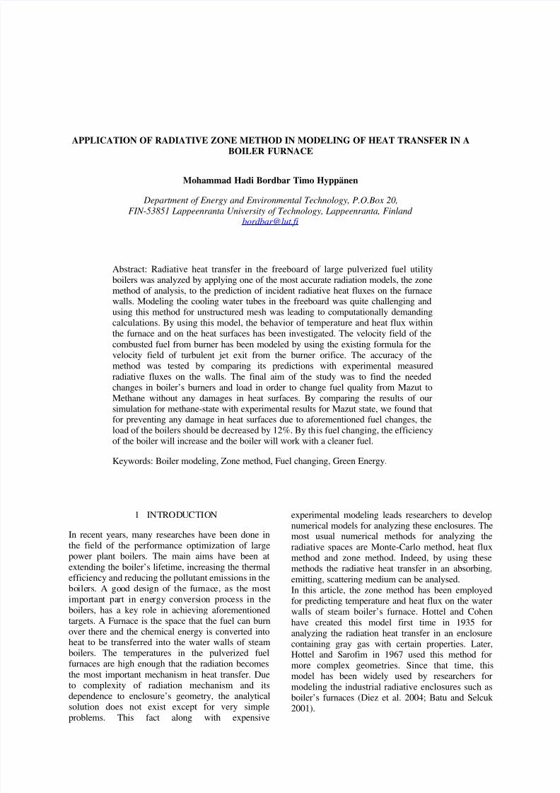
Fig.4.Temperature distribution in volume zones; (a): j=1 the first row of volume zones near the sidewall.(b): j=2 the second row of volume zones.
Figure 4 shows the temperature distribution in thevolume zones in two rows of volume zones, near theside wall and in the central region (j=1, 2 in fig.1).The temperature behaviors in both rows are almostsimilar and in the most regions, the temperature is
uniform. It means that the temperature in the gas isquite high and it decreases near the chimney because
of its effect.Comparison between the calculated data from our
simulation for methane state with experimentalmeasured data which reported by manufacturercompany, give us very useful information for
predicting the actual differences between two states.This information will be useful for changing the loadand work conditions of boiler and its burners in the
way that boiler can work with new fuel, Methane,without any damages in heat surfaces. By comparingthe calculated value for temperature in differentregions of the boiler with experimental reported data,
it is obtained that the temperature in Methane state is
higher than Mazut state by approximately 20 %.
7 CONCLUSIONS AND REMARKS
The zone method is one of the most accurate methodsin simulation radiative heat transfer within theindustrial furnaces but it has some limitation to applyon all furnaces. Complex geometries of real furnacesshould be replaced by simpler shape to be suitable for
using zone method. This method needs the highpower of numerical calculations and finding the bestsize for zones is one of the major criteria in this
method. Choosing very small sized meshing will lead
us to very complex numerical calculation and it canincrease the amount of truncation and round off errorduring the calculation. Whereas, the very coarse
mesh structure will not be able to explain adequatelythe details of the heat transfer phenomena within thefurnace.
In this article, the capability of zone method foranalysing the heat transfer within an industrialfurnace is shown. Solving the flow field within the
furnace is necessary for calculating the convective
heat transfer term in energy balance equations. Usingthe CFD method for solving the velocity field needs a
suitable turbulence model and very fine mesh whichwill increase the calculation time. Furthermore,matching the large zones that are used in zonemethod with this very fine mesh that are used for
CFD calculation will be complex. Due to thesereasons, in this study we used some empiricalequations for calculating the velocity field. An
alternative approach in the further studies is to usefiner mesh for CFD calculations and apply radiationenergy transfer profile of zone method in source
terms of CFD energy equations.
The result of simulation has a good conformity withexisting experimental data. These results are veryuseful for estimating the needed changes in the
burners and the operating conditions of the boilerwhen changing the fuel.By comparing the results of our simulation withexisting data, we found that the temperature of combustion product in the Methane state is higherthan Mazut state by 200-300 Rankine.
Due to higher temperature in Methane state, forpreventing any damage in heat surfaces due toaforementioned fuel changes, we need to decreasetotal entered fuel value. It means that the load of the
boilers should be decreased by 12%. By this fuelchange, the efficiency of the boiler will increase andthe boiler will work with a cleaner fuel.
REFERENCES
Batu, A. and Selçuk, N. (2002). Modeling of Radiative Heat Transfer in the Freeboard of aFluidized Bed Combustor Using the Zone
Method of Analysis. Turkish Journal of
Engineering and Environmental Sciences26,49–58.
Beer, J. M. (1972). Recent advances in the
technology of the furnace flames. J. Inst. Fuel45, 370–382.
Díez L. I.,Cortés C. and Campo A. (2005). Modelingof pulverized coal boilers: review and validationof on-line simulation techniques. Applied
Thermal Engineering 25, 1516–1533.
Hottel H. C. and Cohen E. S. (1935). Radiant heatexchange in a gas-filled enclosure: Allowancefor nonuniformity of gas temperature. AIChE
Journal 4(1), 14–30.Hottel H. C. and Sarofim A.F., (1967). Radiative
Transfer . McGraw-Hill Book Co. New York.Viskanta, R., Menguc, M.P. (1987). Radiation heat
transfer in combustion systems. Progress in Energy and Combustion Science. 13, 97–160.


![Download file [1mb]](https://static.documents.pub/doc/80x56/5875ed8b1a28abe01d8b5089/download-file-1mb.jpg)


