65
ElectraX Handbook ElectraX H a n d b o o k Page 1
ElectraX Handbook
ElectraXH a n d b o o k
Page 1
ElectraX Handbook
Table of ContentsWelcome to ElectraX........................................................................................................................................ 3
Features...................................................................................................................................................... 4How to use this handbook........................................................................................................................... 6Legal Notice................................................................................................................................................. 6
Quick Start........................................................................................................................................................ 7Installation on Windows............................................................................................................................... 7
System requirements.............................................................................................................................. 7Installation procedure............................................................................................................................. 7
Installation on Apple Mac............................................................................................................................. 8System requirements.............................................................................................................................. 8Installation procedure............................................................................................................................. 8
Automatic Installation.........................................................................................................................8Manual Installation............................................................................................................................. 8
ElectraX interface controls........................................................................................................................... 9Buttons................................................................................................................................................... 9Rotary Knobs.......................................................................................................................................... 9Context Menus...................................................................................................................................... 10Previous/Next....................................................................................................................................... 10Display Parameters.............................................................................................................................. 10
Welcome Tutorial............................................................................................................................................ 11The ElectraX User Interface............................................................................................................................ 14
Overview.................................................................................................................................................... 14ElectraX Skins........................................................................................................................................... 15The Rack View........................................................................................................................................... 16
Browser................................................................................................................................................ 16Sound................................................................................................................................................... 19Master Effect......................................................................................................................................... 21
The Editor View......................................................................................................................................... 22The Oscillator Section........................................................................................................................... 23
General Controls............................................................................................................................. 23Oscillator volume and routing controls ............................................................................................26Oscillator waveform controls ...........................................................................................................26
The Filter Section.................................................................................................................................. 34General Controls............................................................................................................................. 34The Filter Display............................................................................................................................. 35
The Insert Effect Section....................................................................................................................... 38The Settings Section............................................................................................................................. 39The Arpeggiator Section....................................................................................................................... 43The Envelope Section........................................................................................................................... 47The Mod Matrix Section........................................................................................................................ 48The LFO Section................................................................................................................................... 53
The Step LFO.................................................................................................................................. 56Appendix......................................................................................................................................................... 58
Effects List ................................................................................................................................................ 58Support and Contact Information...............................................................................................................60Credits....................................................................................................................................................... 61
Page 2
ElectraX Handbook
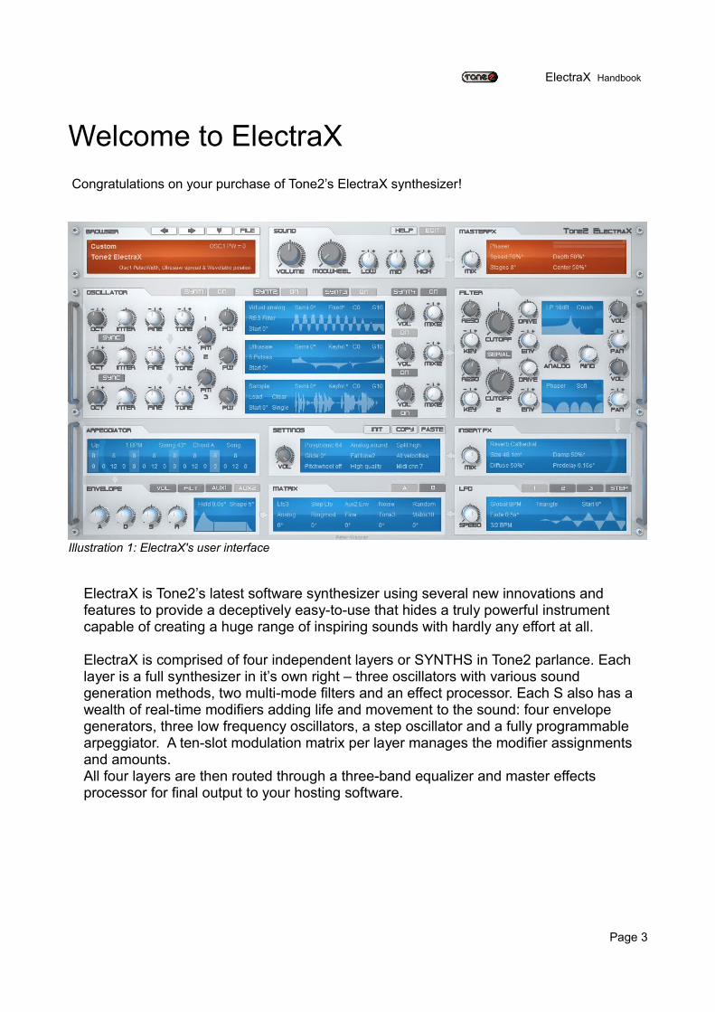
Welcome to ElectraXCongratulations on your purchase of Tone2’s ElectraX synthesizer!
ElectraX is Tone2’s latest software synthesizer using several new innovations and features to provide a deceptively easy-to-use that hides a truly powerful instrument capable of creating a huge range of inspiring sounds with hardly any effort at all.
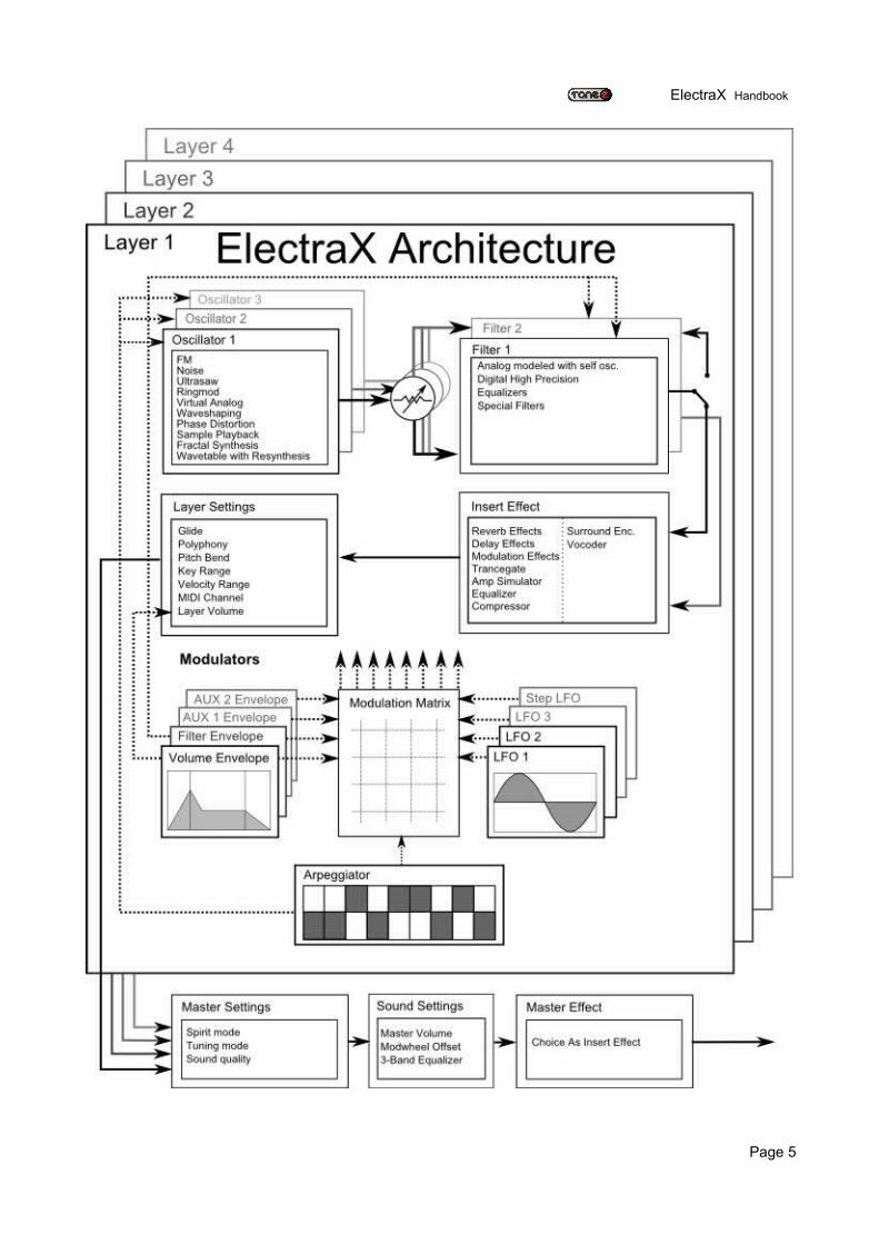
ElectraX is comprised of four independent layers or SYNTHS in Tone2 parlance. Each layer is a full synthesizer in it’s own right – three oscillators with various sound generation methods, two multi-mode filters and an effect processor. Each S also has a wealth of real-time modifiers adding life and movement to the sound: four envelope generators, three low frequency oscillators, a step oscillator and a fully programmable arpeggiator. A ten-slot modulation matrix per layer manages the modifier assignments and amounts.All four layers are then routed through a three-band equalizer and master effects processor for final output to your hosting software.
Page 3
Illustration 1: ElectraX's user interface
ElectraX Handbook
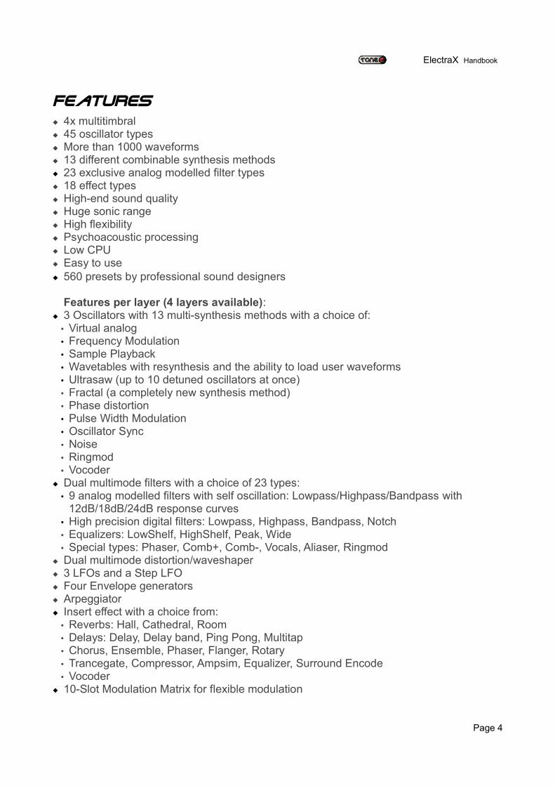
Features 4x multitimbral 45 oscillator types More than 1000 waveforms 13 different combinable synthesis methods 23 exclusive analog modelled filter types 18 effect types High-end sound quality Huge sonic range High flexibility Psychoacoustic processing Low CPU Easy to use 560 presets by professional sound designers
Features per layer (4 layers available): 3 Oscillators with 13 multi-synthesis methods with a choice of: • Virtual analog• Frequency Modulation• Sample Playback• Wavetables with resynthesis and the ability to load user waveforms• Ultrasaw (up to 10 detuned oscillators at once)• Fractal (a completely new synthesis method)• Phase distortion• Pulse Width Modulation• Oscillator Sync• Noise• Ringmod• Vocoder
Dual multimode filters with a choice of 23 types:• 9 analog modelled filters with self oscillation: Lowpass/Highpass/Bandpass with
12dB/18dB/24dB response curves• High precision digital filters: Lowpass, Highpass, Bandpass, Notch• Equalizers: LowShelf, HighShelf, Peak, Wide• Special types: Phaser, Comb+, Comb-, Vocals, Aliaser, Ringmod
Dual multimode distortion/waveshaper 3 LFOs and a Step LFO Four Envelope generators Arpeggiator Insert effect with a choice from:• Reverbs: Hall, Cathedral, Room• Delays: Delay, Delay band, Ping Pong, Multitap• Chorus, Ensemble, Phaser, Flanger, Rotary• Trancegate, Compressor, Ampsim, Equalizer, Surround Encode• Vocoder
10-Slot Modulation Matrix for flexible modulation
Page 4
ElectraX Handbook
Page 5
ElectraX Handbook
How to use this handbookThis handbook has been designed to provide a “quick start” guide to start making great sounds straight away with ElectraX, followed by a more detailed explanation of ElectraX, the user interface and its functions for power users and those who like to go beyond the presets.
What this handbook doesn’t do is explain the fundamentals of synthesis – there are plenty of good information available elsewhere. A good search on the internet will provide all the information you ever need for learning the basics.
Information and Warnings in the handbook are shown with a grey background.
New users should continue reading onto the Quick Start section.
For a how-to tutorial on building a basic bass patch, hop to page 11.
For a more in-depth explanation of ElectraX’s functions skip to page 16.
Legal Notice
The licence included in the keyfile is a single user licence for an installation on a single computer. Please contact our support team if you need additional licences.
This product is copy protected and uses audio watermarks.
Tone2 will deactivate licences of users who share our software without permission. Violators will be excluded from customer resources, services and updates.
Under the DMCA, copying and sharing copyrighted materials without a license is illegal, violations to copyright law may carry heavy civil and criminal penalties.
Page 6
ElectraX Handbook
Quick StartThis section will get you going straight away.
Installation procedure
Together with the download link from Share-it you have received a keyfile called 'ElectraX.t2k' to unlock the full version, you will find as an email attachment. This keyfile contains your personal serial number with your name and is used to unlock the full version.
Please note: Installation on Windows7 & Vista need to be done from an administrator's account or by using 'Run as Administrator' for both the ElectraX installer and host program.
Automatic Installation (recommended)1. Close your host (Logic, Live, Cubase, etc.).
2. Install the full version of the plugin. Note that the demo version can not be unlocked.
3. Open your host.
4. Do a plugin rescan in the host if it does not list ElectraX as plugin. Detailed instructions for the rescan are found in your host's manual.
5. Open ElectraX.
6. Click on the registration box in the middle.
7. Select the keyfile 'ElectraX.t2k' to activate the full version.
8. Restart the plugin. Now the normal user interface appears. Some hosts may require a complete restart.
Page 7
ElectraX Handbook
Manual Installation on Windows1. Close your host (Cubase, Sonar, Samplitude, Live, etc.).
2. Install the full version of the plugin. Note: the demo version can not be unlocked.
3. Copy 'ElectraX.t2k' to the VST directory. Steinberg hosts often use C:\Program files\Steinberg\VSTplugins as the default plugin path. You can also take a look at your host's folder configuration. Generally, the correct path for the keyfile is 'C:\Program Files\Steinberg\VSTplugins\ElectraX.t2k'Note that the 'ElectraX.t2k' keyfile should be inside the same folder the ElectraX.dll is.
4. Open your host.
5. Do a plugin rescan in the host if it does not list ElectraX as plugin. Detailed instructions for the rescan are found in your host's manual.
6. Open ElectraX. Now the normal user interface appears. If this is not the case close your host and go back to step 3 as most likely you did not copy the keyfile to the right place.
Manual Installation on Apple Mac1. Close your host (Logic, Digital Performer, Live, Cubase, etc.).
2. Install the full version of the plugin. Note: the demo version can not be unlocked.
3. Copy 'ElectraX.t2k' to 'Library/Audio/Plug-ins' . The correct path for the file is: '/Library/Audio/Plug-ins/ElectraX.t2k'. Please note: '/Users/Username/Library/Audio/Plug-Ins/' is NOT the correct path. Filenames on Unix based systems like OSX are case sensitive!
4. Open the host.
5. Do a plugin rescan in the host if it does not list ElectraX as plugin. Detailed instructions for the rescan be found in your host's manual.
6. Open ElectraX. Now the normal user interface appears. If this is not the case close your host and go back to step 3 as most likely you did not copy the keyfile to the right place.
Page 8
ElectraX Handbook
ElectraX interface controls
Buttons
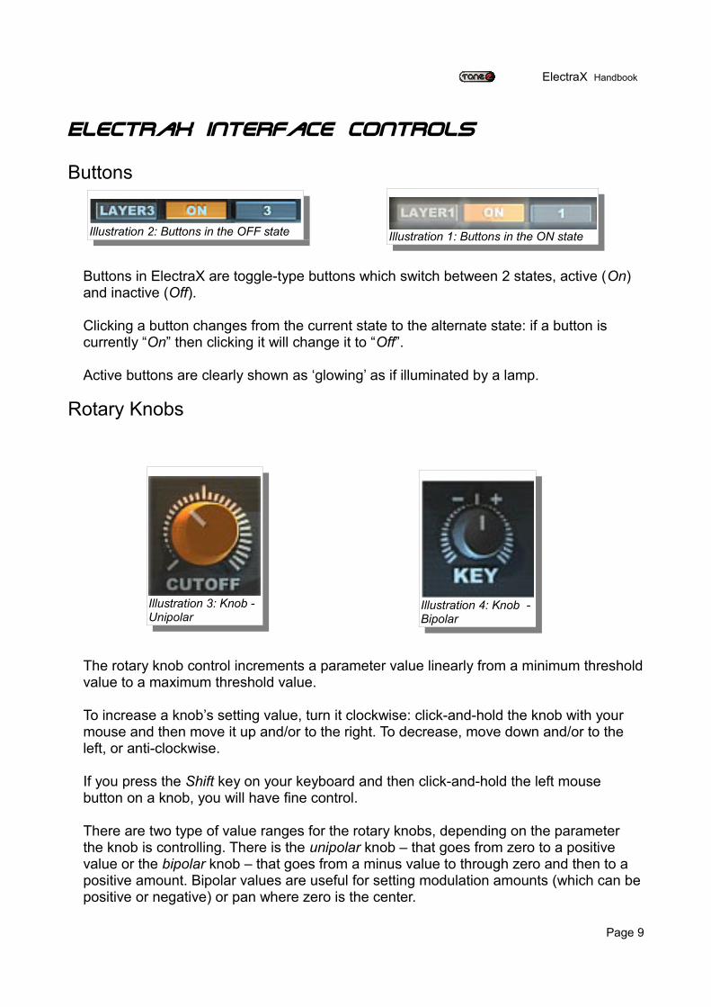
Buttons in ElectraX are toggle-type buttons which switch between 2 states, active (On) and inactive (Off).
Clicking a button changes from the current state to the alternate state: if a button is currently “On” then clicking it will change it to “Off”.
Active buttons are clearly shown as ‘glowing’ as if illuminated by a lamp.
Rotary Knobs
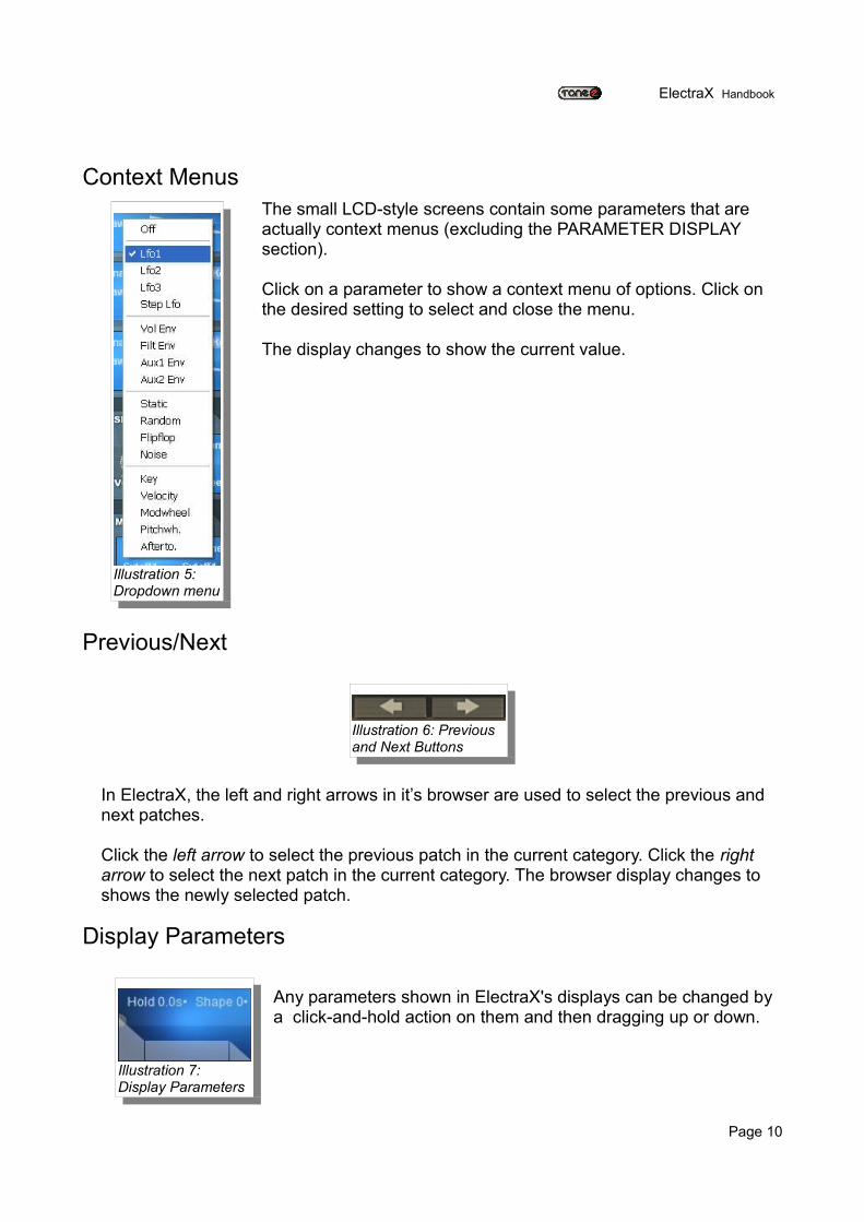
The rotary knob control increments a parameter value linearly from a minimum threshold value to a maximum threshold value.
To increase a knob’s setting value, turn it clockwise: click-and-hold the knob with your mouse and then move it up and/or to the right. To decrease, move down and/or to the left, or anti-clockwise.
If you press the Shift key on your keyboard and then click-and-hold the left mouse button on a knob, you will have fine control.
There are two type of value ranges for the rotary knobs, depending on the parameter the knob is controlling. There is the unipolar knob – that goes from zero to a positive value or the bipolar knob – that goes from a minus value to through zero and then to a positive amount. Bipolar values are useful for setting modulation amounts (which can be positive or negative) or pan where zero is the center.
Page 9
Illustration 2: Buttons in the OFF state
Illustration 3: Knob - Unipolar
Illustration 4: Knob - Bipolar
Illustration 1: Buttons in the ON state
ElectraX Handbook
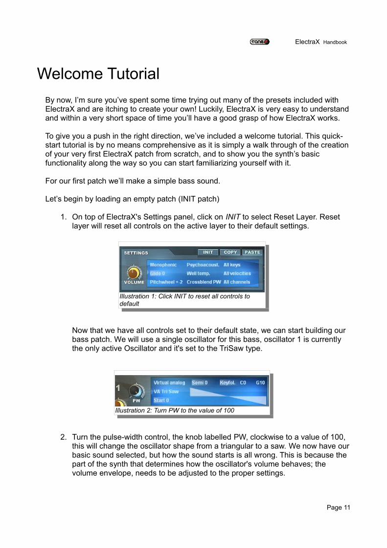
Context MenusThe small LCD-style screens contain some parameters that are actually context menus (excluding the PARAMETER DISPLAY section).
Click on a parameter to show a context menu of options. Click on the desired setting to select and close the menu.
The display changes to show the current value.
Previous/Next
In ElectraX, the left and right arrows in it’s browser are used to select the previous and next patches.
Click the left arrow to select the previous patch in the current category. Click the right arrow to select the next patch in the current category. The browser display changes to shows the newly selected patch.
Display Parameters
Any parameters shown in ElectraX's displays can be changed by a click-and-hold action on them and then dragging up or down.
Page 10
Illustration 5: Dropdown menu
Illustration 6: Previous and Next Buttons
Illustration 7: Display Parameters
ElectraX Handbook
Welcome TutorialBy now, I’m sure you’ve spent some time trying out many of the presets included with ElectraX and are itching to create your own! Luckily, ElectraX is very easy to understand and within a very short space of time you’ll have a good grasp of how ElectraX works.
To give you a push in the right direction, we’ve included a welcome tutorial. This quick-start tutorial is by no means comprehensive as it is simply a walk through of the creation of your very first ElectraX patch from scratch, and to show you the synth’s basic functionality along the way so you can start familiarizing yourself with it.
For our first patch we’ll make a simple bass sound.
Let’s begin by loading an empty patch (INIT patch)
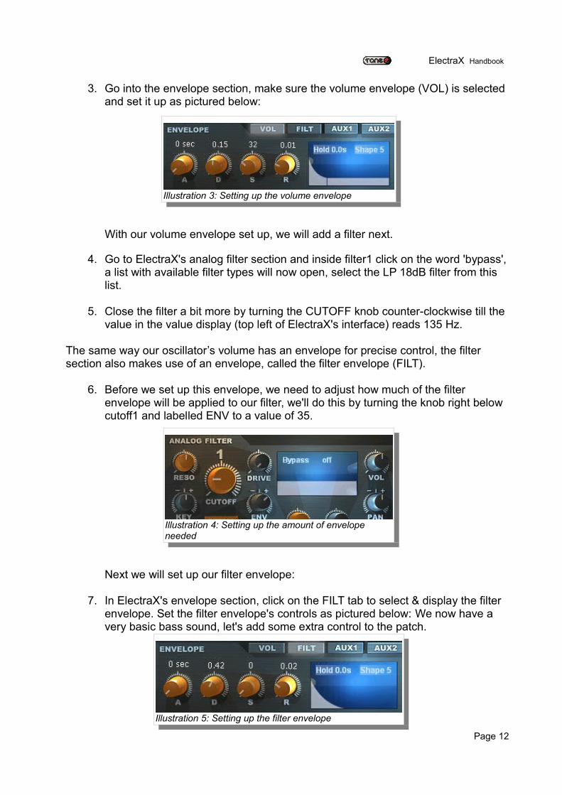
1. On top of ElectraX's Settings panel, click on INIT to select Reset Layer. Reset layer will reset all controls on the active layer to their default settings.
Now that we have all controls set to their default state, we can start building our bass patch. We will use a single oscillator for this bass, oscillator 1 is currently the only active Oscillator and it's set to the TriSaw type.
2. Turn the pulse-width control, the knob labelled PW, clockwise to a value of 100, this will change the oscillator shape from a triangular to a saw. We now have our basic sound selected, but how the sound starts is all wrong. This is because the part of the synth that determines how the oscillator's volume behaves; the volume envelope, needs to be adjusted to the proper settings.
Page 11
Illustration 1: Click INIT to reset all controls to default
Illustration 2: Turn PW to the value of 100
ElectraX Handbook
3. Go into the envelope section, make sure the volume envelope (VOL) is selected and set it up as pictured below:
With our volume envelope set up, we will add a filter next.
4. Go to ElectraX's analog filter section and inside filter1 click on the word 'bypass', a list with available filter types will now open, select the LP 18dB filter from this list.
5. Close the filter a bit more by turning the CUTOFF knob counter-clockwise till the value in the value display (top left of ElectraX's interface) reads 135 Hz.
The same way our oscillator’s volume has an envelope for precise control, the filter section also makes use of an envelope, called the filter envelope (FILT).
6. Before we set up this envelope, we need to adjust how much of the filter envelope will be applied to our filter, we'll do this by turning the knob right below cutoff1 and labelled ENV to a value of 35.
Next we will set up our filter envelope:
7. In ElectraX's envelope section, click on the FILT tab to select & display the filter envelope. Set the filter envelope's controls as pictured below: We now have a very basic bass sound, let's add some extra control to the patch.
Page 12
Illustration 3: Setting up the volume envelope
Illustration 4: Setting up the amount of envelope needed
Illustration 5: Setting up the filter envelope
ElectraX Handbook
Let start by assigning the modulation wheel to the filter, that way we can open and close our 18dB filter by simply using the modulation wheel on our controller.
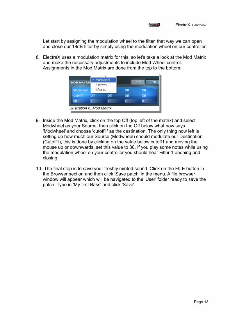
8. ElectraX uses a modulation matrix for this, so let's take a look at the Mod Matrix and make the necessary adjustments to include Mod Wheel control. Assignments in the Mod Matrix are done from the top to the bottom:
9. Inside the Mod Matrix, click on the top Off (top left of the matrix) and select Modwheel as your Source, then click on the Off below what now says 'Modwheel' and choose 'cutoff1' as the destination. The only thing now left is setting up how much our Source (Modwheel) should modulate our Destination (Cutoff1), this is done by clicking on the value below cutoff1 and moving the mouse up or downwards, set this value to 30. If you play some notes while using the modulation wheel on your controller you should hear Filter 1 opening and closing.
10. The final step is to save your freshly minted sound. Click on the FILE button in the Browser section and then click 'Save patch' in the menu. A file browser window will appear which will be navigated to the 'User' folder ready to save the patch. Type in 'My first Bass' and click 'Save'.
Page 13
Illustration 6: Mod Matrix
ElectraX Handbook
The ElectraX User Interface
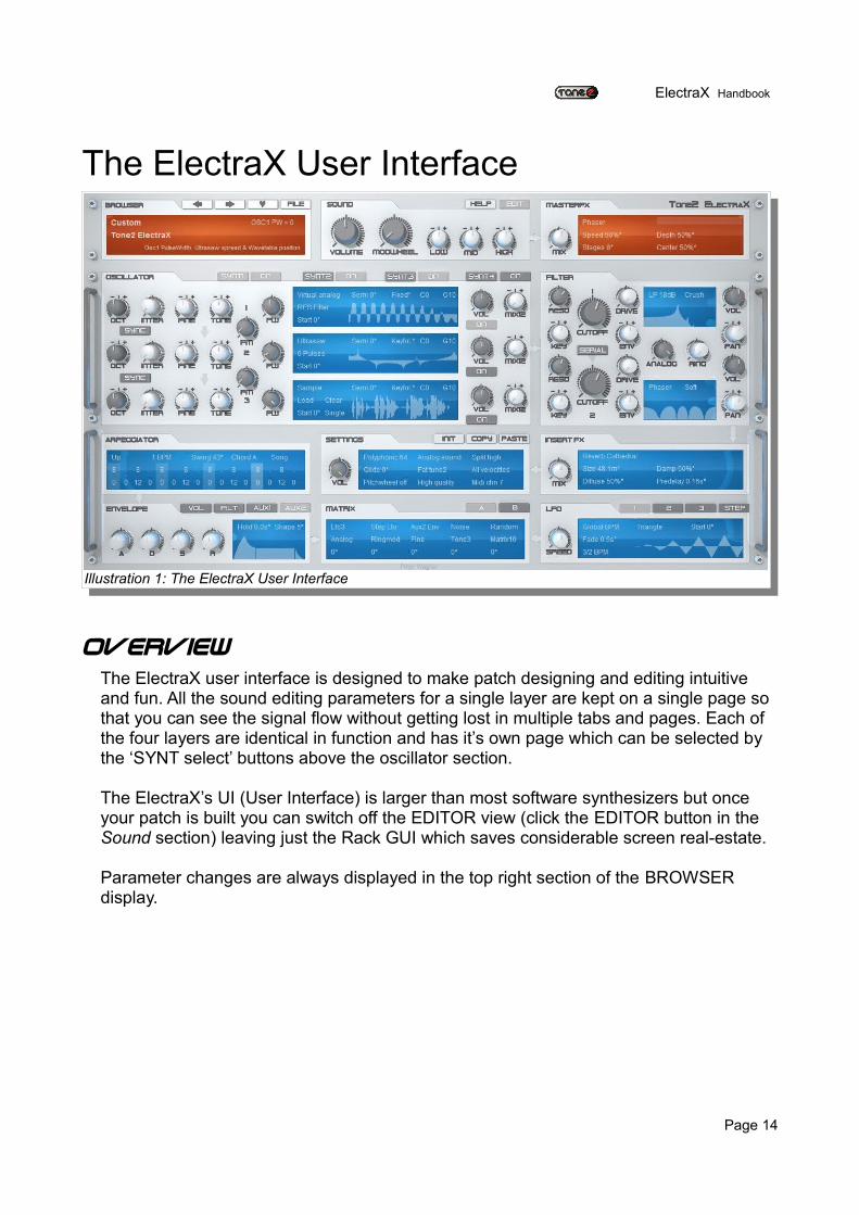
OverviewThe ElectraX user interface is designed to make patch designing and editing intuitive and fun. All the sound editing parameters for a single layer are kept on a single page so that you can see the signal flow without getting lost in multiple tabs and pages. Each of the four layers are identical in function and has it’s own page which can be selected by the ‘SYNT select’ buttons above the oscillator section.
The ElectraX’s UI (User Interface) is larger than most software synthesizers but once your patch is built you can switch off the EDITOR view (click the EDITOR button in the Sound section) leaving just the Rack GUI which saves considerable screen real-estate.
Parameter changes are always displayed in the top right section of the BROWSER display.
Page 14
Illustration 1: The ElectraX User Interface
ElectraX Handbook
ElectraX Skins
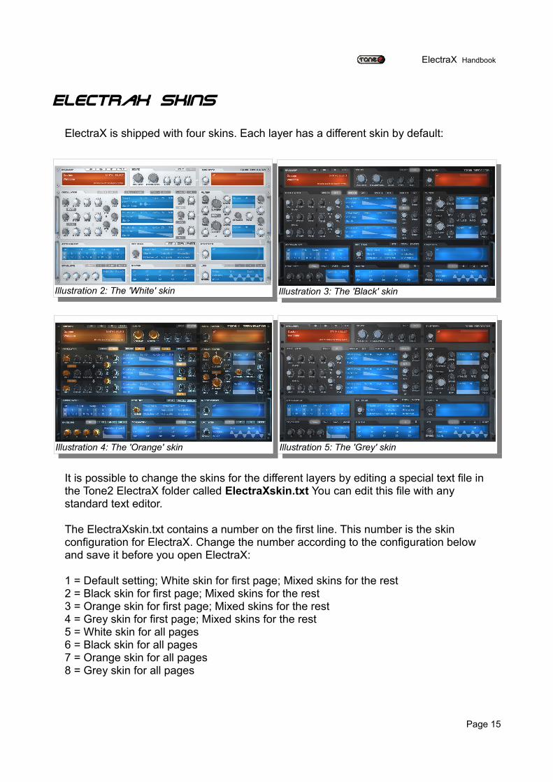
ElectraX is shipped with four skins. Each layer has a different skin by default:
It is possible to change the skins for the different layers by editing a special text file in the Tone2 ElectraX folder called ElectraXskin.txt You can edit this file with any standard text editor.
The ElectraXskin.txt contains a number on the first line. This number is the skin configuration for ElectraX. Change the number according to the configuration below and save it before you open ElectraX:
1 = Default setting; White skin for first page; Mixed skins for the rest 2 = Black skin for first page; Mixed skins for the rest 3 = Orange skin for first page; Mixed skins for the rest 4 = Grey skin for first page; Mixed skins for the rest 5 = White skin for all pages 6 = Black skin for all pages 7 = Orange skin for all pages 8 = Grey skin for all pages
Page 15
Illustration 2: The 'White' skin Illustration 3: The 'Black' skin
Illustration 4: The 'Orange' skin Illustration 5: The 'Grey' skin
ElectraX Handbook
The Rack View
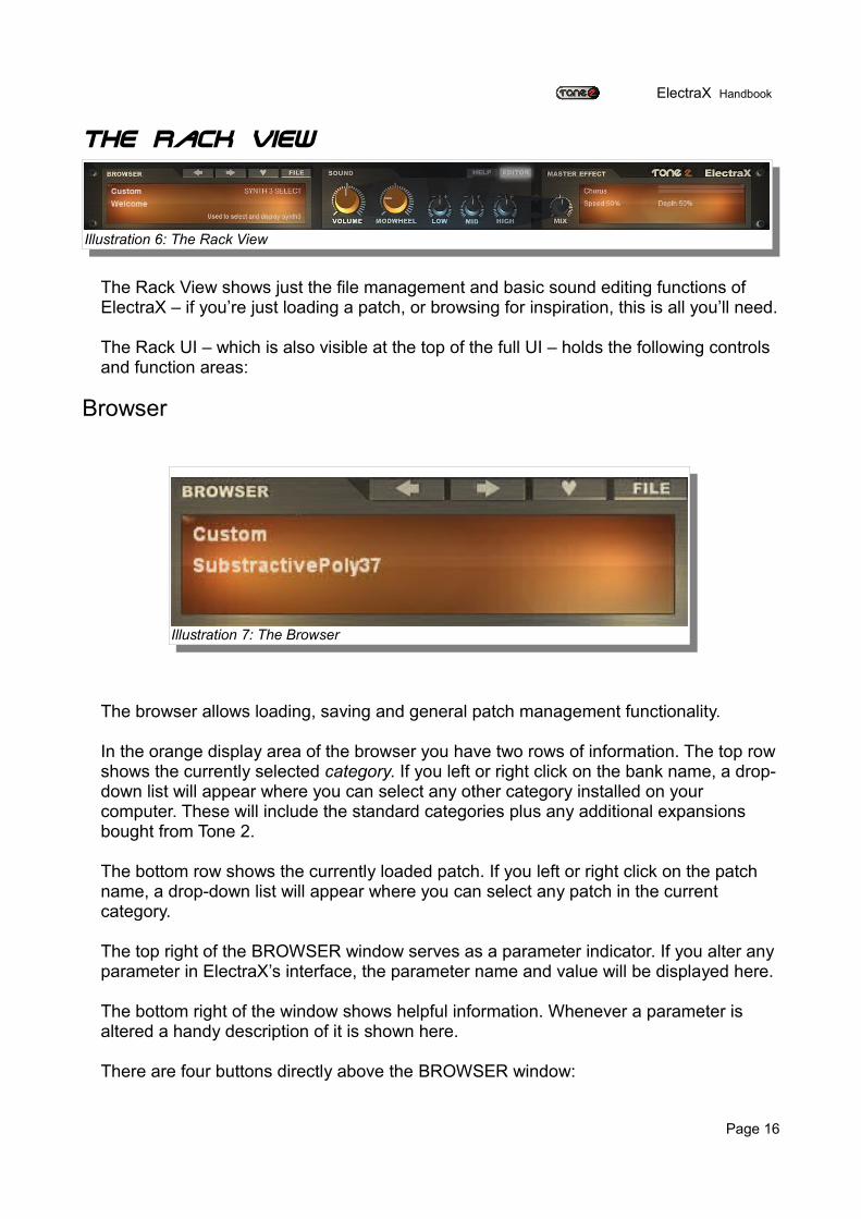
The Rack View shows just the file management and basic sound editing functions of ElectraX – if you’re just loading a patch, or browsing for inspiration, this is all you’ll need.
The Rack UI – which is also visible at the top of the full UI – holds the following controls and function areas:
Browser
The browser allows loading, saving and general patch management functionality.
In the orange display area of the browser you have two rows of information. The top row shows the currently selected category. If you left or right click on the bank name, a drop-down list will appear where you can select any other category installed on your computer. These will include the standard categories plus any additional expansions bought from Tone 2.
The bottom row shows the currently loaded patch. If you left or right click on the patch name, a drop-down list will appear where you can select any patch in the current category.
The top right of the BROWSER window serves as a parameter indicator. If you alter any parameter in ElectraX’s interface, the parameter name and value will be displayed here.
The bottom right of the window shows helpful information. Whenever a parameter is altered a handy description of it is shown here.
There are four buttons directly above the BROWSER window:
Page 16
Illustration 6: The Rack View
Illustration 7: The Browser
ElectraX Handbook
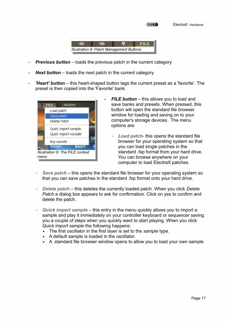
• Previous button – loads the previous patch in the current category
• Next button – loads the next patch in the current category
• 'Heart' button – this heart-shaped button tags the current preset as a 'favorite'. The preset is then copied into the 'Favorite' bank.
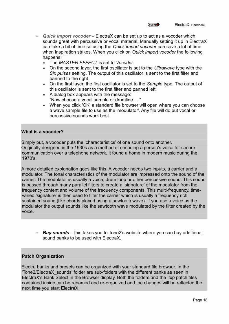
• FILE button – this allows you to load and save banks and presets. When pressed, this button will open the standard file browser window for loading and saving on to your computer's storage devices. The menu options are:
◦ Load patch- this opens the standard file browser for your operating system so that you can load single patches in the standard .fxp format from your hard drive. You can browse anywhere on your computer to load ElectraX patches.
◦ Save patch – this opens the standard file browser for your operating system so that you can save patches in the standard .fxp format onto your hard drive.
◦ Delete patch – this deletes the currently loaded patch. When you click Delete Patch a dialog box appears to ask for confirmation. Click on yes to confirm and delete the patch.
◦ Quick import sample – this entry in the menu quickly allows you to import a sample and play it immediately on your controller keyboard or sequencer saving you a couple of steps when you quickly want to start playing. When you click Quick import sample the following happens:▪ The first oscillator in the first layer is set to the sample type.▪ A default sample is loaded in the oscillator.▪ A standard file browser window opens to allow you to load your own sample.
Page 17
Illustration 8: Patch Management Buttons
Illustration 9: The FILE context menu
ElectraX Handbook
◦ Quick import vocoder – ElectraX can be set up to act as a vocoder which sounds great with percussive or vocal material. Manually setting it up in ElectraX can take a bit of time so using the Quick import vocoder can save a lot of time when inspiration strikes. When you click on Quick import vocoder the following happens:▪ The MASTER EFFECT is set to Vocoder. ▪ On the second layer, the first oscillator is set to the Ultrawave type with the
Six pulses setting. The output of this oscillator is sent to the first filter and panned to the right.
▪ On the first layer, the first oscillator is set to the Sample type. The output of this oscillator is sent to the first filter and panned left.
▪ A dialog box appears with the message:“Now choose a vocal sample or drumline.....”
▪ When you click 'OK' a standard file browser will open where you can choose a wave sample file to use as the 'modulator'. Any file will do but vocal or percussive sounds work best.
What is a vocoder?
Simply put, a vocoder puts the ‘characteristics’ of one sound onto another.Originally designed in the 1930s as a method of encoding a person’s voice for secure communication over a telephone network, it found a home in modern music during the 1970’s.
A more detailed explanation goes like this. A vocoder needs two inputs, a carrier and a modulator. The tonal characteristics of the modulator are impressed onto the sound of the carrier. The modulator is usually a voice, drum loop or other percussive sound. This sound is passed through many parallel filters to create a ‘signature’ of the modulator from the frequency content and volume of the frequency components. This multi-frequency, time-varied ‘signature’ is then used to filter the carrier which is usually a frequency rich sustained sound (like chords played using a sawtooth wave). If you use a voice as the modulator the output sounds like the sawtooth wave modulated by the filter created by the voice.
◦ Buy sounds – this takes you to Tone2's website where you can buy additional sound banks to be used with ElectraX.
Patch Organization
Electra banks and presets can be organized with your standard file browser. In the 'Tone2/ElectraX_sounds' folder are sub-folders with the different banks as seen in ElectraX's Bank Select in the Browser display. Both the folders and the .fxp patch files contained inside can be renamed and re-organized and the changes will be reflected the next time you start ElectraX.
Page 18
ElectraX Handbook
Sound
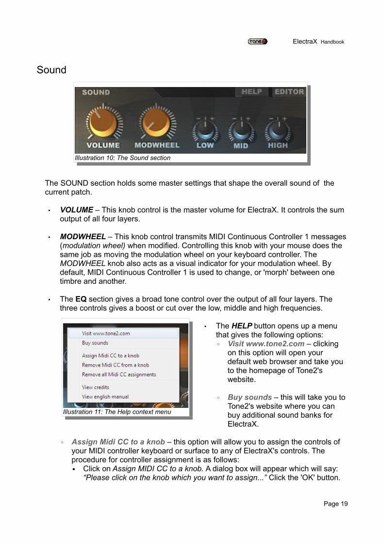
The SOUND section holds some master settings that shape the overall sound of the current patch.
• VOLUME – This knob control is the master volume for ElectraX. It controls the sum output of all four layers.
• MODWHEEL – This knob control transmits MIDI Continuous Controller 1 messages (modulation wheel) when modified. Controlling this knob with your mouse does the same job as moving the modulation wheel on your keyboard controller. The MODWHEEL knob also acts as a visual indicator for your modulation wheel. By default, MIDI Continuous Controller 1 is used to change, or 'morph' between one timbre and another.
• The EQ section gives a broad tone control over the output of all four layers. The three controls gives a boost or cut over the low, middle and high frequencies.
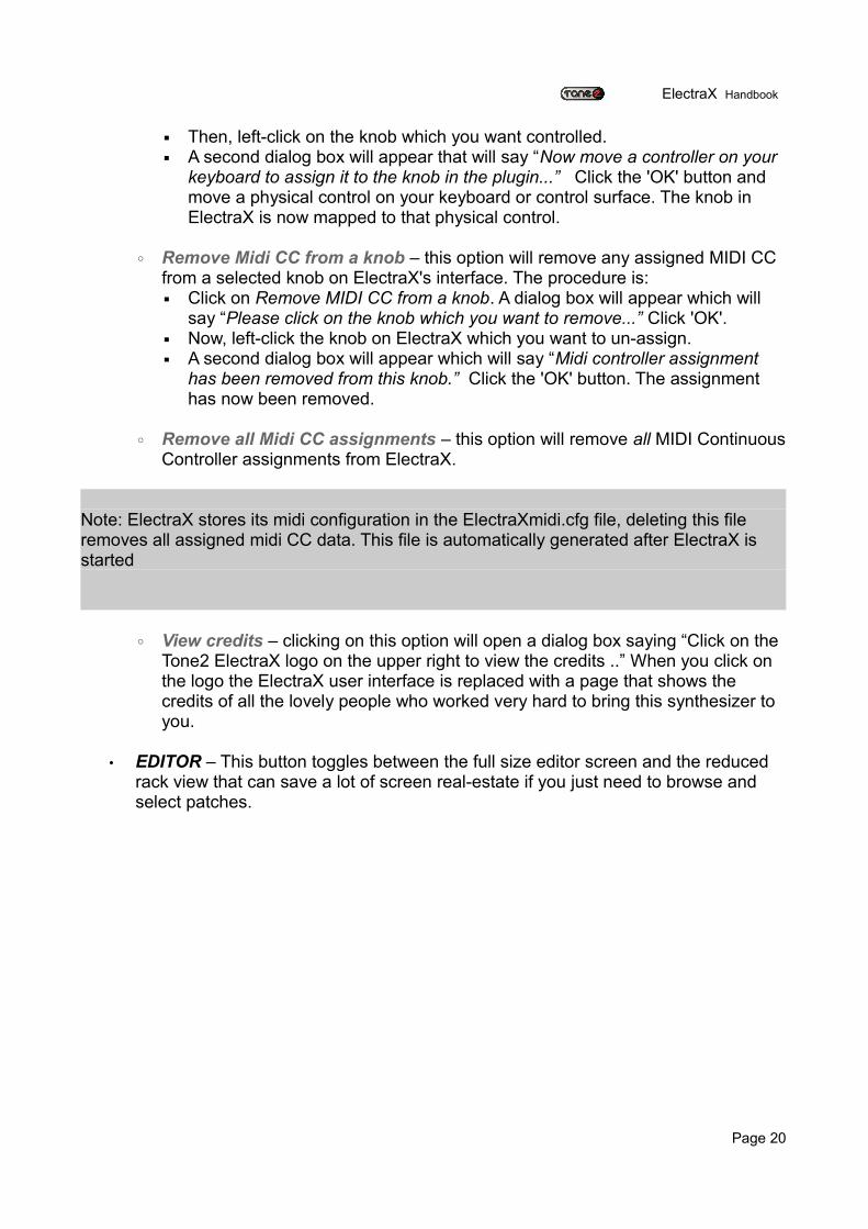
• The HELP button opens up a menu that gives the following options:◦ Visit www.tone2.com – clicking
on this option will open your default web browser and take you to the homepage of Tone2's website.
◦ Buy sounds – this will take you to Tone2's website where you can buy additional sound banks for ElectraX.
◦ Assign Midi CC to a knob – this option will allow you to assign the controls of your MIDI controller keyboard or surface to any of ElectraX's controls. The procedure for controller assignment is as follows:▪ Click on Assign MIDI CC to a knob. A dialog box will appear which will say:
“Please click on the knob which you want to assign...” Click the 'OK' button.
Page 19
Illustration 10: The Sound section
Illustration 11: The Help context menu
ElectraX Handbook
▪ Then, left-click on the knob which you want controlled.▪ A second dialog box will appear that will say “Now move a controller on your
keyboard to assign it to the knob in the plugin...” Click the 'OK' button and move a physical control on your keyboard or control surface. The knob in ElectraX is now mapped to that physical control.
◦ Remove Midi CC from a knob – this option will remove any assigned MIDI CC from a selected knob on ElectraX's interface. The procedure is:▪ Click on Remove MIDI CC from a knob. A dialog box will appear which will
say “Please click on the knob which you want to remove...” Click 'OK'.▪ Now, left-click the knob on ElectraX which you want to un-assign.▪ A second dialog box will appear which will say “Midi controller assignment
has been removed from this knob.” Click the 'OK' button. The assignment has now been removed.
◦ Remove all Midi CC assignments – this option will remove all MIDI Continuous Controller assignments from ElectraX.
Note: ElectraX stores its midi configuration in the ElectraXmidi.cfg file, deleting this file removes all assigned midi CC data. This file is automatically generated after ElectraX is started
◦ View credits – clicking on this option will open a dialog box saying “Click on the Tone2 ElectraX logo on the upper right to view the credits ..” When you click on the logo the ElectraX user interface is replaced with a page that shows the credits of all the lovely people who worked very hard to bring this synthesizer to you.
• EDITOR – This button toggles between the full size editor screen and the reduced rack view that can save a lot of screen real-estate if you just need to browse and select patches.
Page 20
ElectraX Handbook
Master Effect
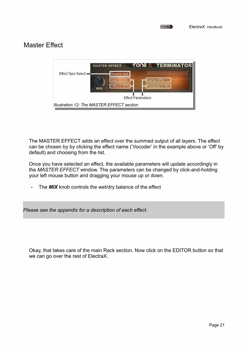
The MASTER EFFECT adds an effect over the summed output of all layers. The effect can be chosen by by clicking the effect name (’Vocoder’ in the example above or ‘Off’ by default) and choosing from the list.
Once you have selected an effect, the available parameters will update accordingly in the MASTER EFFECT window. The parameters can be changed by click-and-holding your left mouse button and dragging your mouse up or down.
• The MIX knob controls the wet/dry balance of the effect
Please see the appendix for a description of each effect.
Okay, that takes care of the main Rack section. Now click on the EDITOR button so that we can go over the rest of ElectraX.
Page 21
Illustration 12: The MASTER EFFECT section
ElectraX Handbook
The Editor View
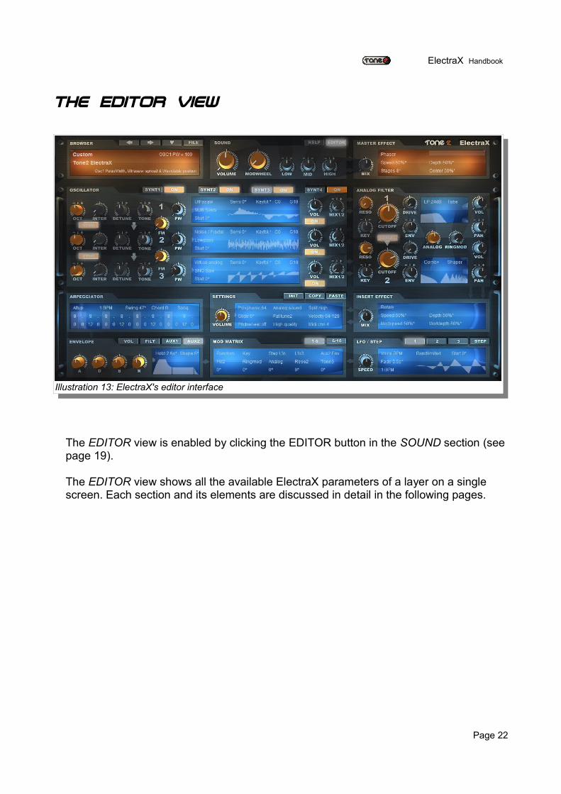
The EDITOR view is enabled by clicking the EDITOR button in the SOUND section (see page 19).
The EDITOR view shows all the available ElectraX parameters of a layer on a single screen. Each section and its elements are discussed in detail in the following pages.
Page 22
Illustration 13: ElectraX's editor interface
ElectraX Handbook
The Oscillator Section
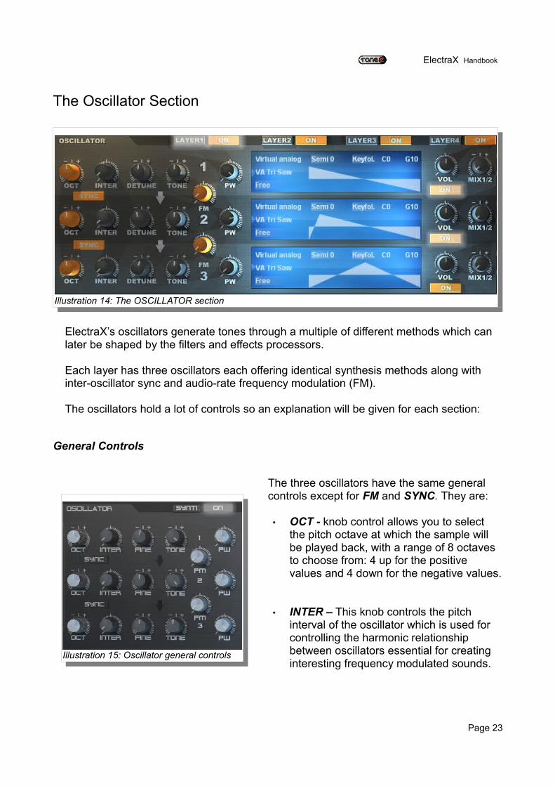
ElectraX’s oscillators generate tones through a multiple of different methods which can later be shaped by the filters and effects processors.
Each layer has three oscillators each offering identical synthesis methods along with inter-oscillator sync and audio-rate frequency modulation (FM).
The oscillators hold a lot of controls so an explanation will be given for each section:
General Controls
The three oscillators have the same general controls except for FM and SYNC. They are:
• OCT - knob control allows you to select the pitch octave at which the sample will be played back, with a range of 8 octaves to choose from: 4 up for the positive values and 4 down for the negative values.
• INTER – This knob controls the pitch interval of the oscillator which is used for controlling the harmonic relationship between oscillators essential for creating interesting frequency modulated sounds.
Page 23
Illustration 14: The OSCILLATOR section
Illustration 15: Oscillator general controls
ElectraX Handbook
In the browser window, the parameter readout for the INTER control is showed as a ratio. This ratio shows the INTERval between the frequency of the carrier oscillator and the modulating oscillator (for an explanation of the basics of FM synthesis, see below). The intervals with a harmonic relationship with the bottom (fundamental) note will sound consonant or ‘pleasing’ to the ear. If the interval doesn’t have a harmonic relationship then the sound will be dissonant. This is useful in FM synthesis for creating bell type tones.The classic names of the intervals are given below and whether they are consonant or dissonant:
1 Unison Consonant6/5 Minor Third Consonant5/4 Major Third Consonant4/3 Perfect Fourth Consonant3/2 Perfect Fifth Consonant5/3 Major Sixth Consonant7/4 Augmented Sixth Dissonant
• FINE – This knob controls the fine tuning of the oscillator. The range is plus or minus 100 cents. There are 100 cents per semitone.
• TONE - This knob is a basic tone control that can make the oscillator darker or brighter. This can be used to give an oscillator a bit more 'bite', or can be used to control the higher harmonics for frequency modulation.
• PW is short for Pulse Width and has various functions depending on what synthesis method is selected for the oscillator:
◦ In the Virtual Analog mode, the PW controls either: ▪ The waveform pulsewidth. ▪ Wavetable position.
◦ In the Ultrasaw mode, the PW controls both:
▪ Oscillator detune.▪ The waveform pulsewidth.
◦ In the Wavetable mode, the PW controls the sample waveform pulse-width.
◦ In Noise/Fractal mode PW controls Noise configuration or Fractal chaos level◦◦ In Sample mode PW has no effect.
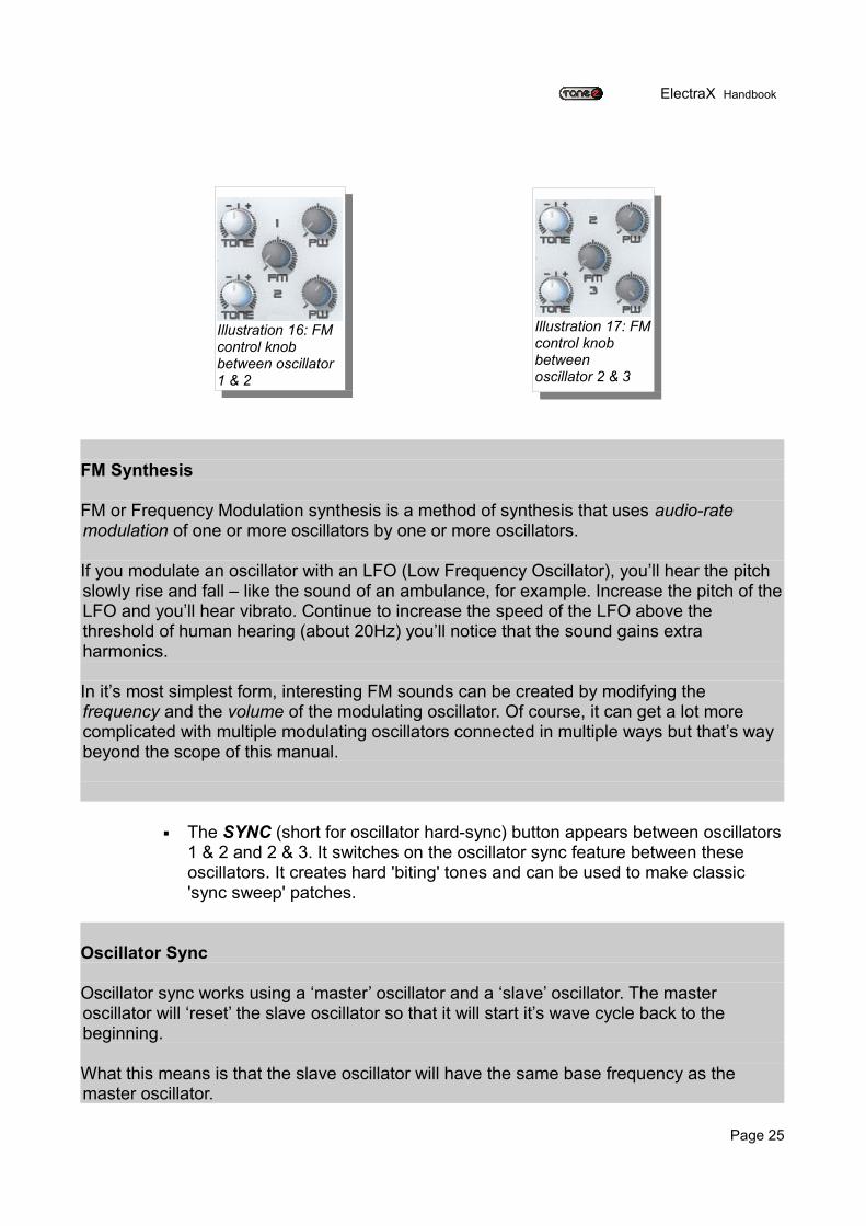
• FM – This knob appears between oscillators 1 & 2 and between 2 & 3. The knob between oscillator 1 &2 controls the amount of audio signal from oscillator 1 modulates oscillator 2. The knob between oscillator 2 & 3 controls the amount of audio signal from oscillator 2 modulates oscillator 3.
Page 24
ElectraX Handbook
FM Synthesis
FM or Frequency Modulation synthesis is a method of synthesis that uses audio-rate modulation of one or more oscillators by one or more oscillators.
If you modulate an oscillator with an LFO (Low Frequency Oscillator), you’ll hear the pitch slowly rise and fall – like the sound of an ambulance, for example. Increase the pitch of the LFO and you’ll hear vibrato. Continue to increase the speed of the LFO above the threshold of human hearing (about 20Hz) you’ll notice that the sound gains extra harmonics.
In it’s most simplest form, interesting FM sounds can be created by modifying the frequency and the volume of the modulating oscillator. Of course, it can get a lot more complicated with multiple modulating oscillators connected in multiple ways but that’s way beyond the scope of this manual.
▪ The SYNC (short for oscillator hard-sync) button appears between oscillators 1 & 2 and 2 & 3. It switches on the oscillator sync feature between these oscillators. It creates hard 'biting' tones and can be used to make classic 'sync sweep' patches.
Oscillator Sync
Oscillator sync works using a ‘master’ oscillator and a ‘slave’ oscillator. The master oscillator will ‘reset’ the slave oscillator so that it will start it’s wave cycle back to the beginning.
What this means is that the slave oscillator will have the same base frequency as the master oscillator.
Page 25
Illustration 16: FM control knob between oscillator 1 & 2
Illustration 17: FM control knob between oscillator 2 & 3
ElectraX Handbook
Interesting things happen when the pitch of the slave is changed either manually or through modulation. The classic ‘hard sync’ sound can be created this way.
Note that there are two types of sync – hard and soft. Hard sync is the most common and is the one most people recognize as the definitive ‘hard sync sound’.
Oscillator volume and routing controls
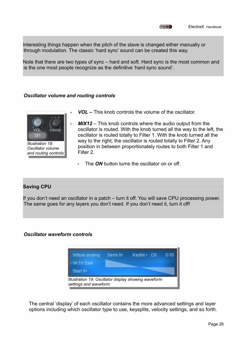
• VOL – This knob controls the volume of the oscillator.
• MIX12 – This knob controls where the audio output from the oscillator is routed. With the knob turned all the way to the left, the oscillator is routed totally to Filter 1. With the knob turned all the way to the right, the oscillator is routed totally to Filter 2. Any position in between proportionately routes to both Filter 1 and Filter 2.
• The ON button turns the oscillator on or off.
Saving CPU
If you don’t need an oscillator in a patch – turn it off. You will save CPU processing power. The same goes for any layers you don’t need. If you don’t need it, turn it off!
Oscillator waveform controls
The central ‘display’ of each oscillator contains the more advanced settings and layer options including which oscillator type to use, keysplits, velocity settings, and so forth.
Page 26
Illustration 18: Oscillator volume and routing controls
Illustration 19: Oscillator display showing waveform settings and waveform
ElectraX Handbook
The waveform display updates in real-time (like an oscilloscope) to give you a visual representation of the oscillator waveform and any modulators that are affecting it.
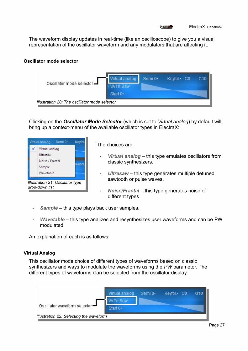
Oscillator mode selector
Clicking on the Oscillator Mode Selector (which is set to Virtual analog) by default will bring up a context-menu of the available oscillator types in ElectraX:
The choices are:
• Virtual analog – this type emulates oscillators from classic synthesizers.
• Ultrasaw – this type generates multiple detuned sawtooth or pulse waves.
• Noise/Fractal – this type generates noise of different types.
• Sample – this type plays back user samples.
• Wavetable – this type analizes and resynthesizes user waveforms and can be PW modulated.
An explanation of each is as follows:
Virtual Analog
This oscillator mode choice of different types of waveforms based on classic synthesizers and ways to modulate the waveforms using the PW parameter. The different types of waveforms clan be selected from the oscillator display.
Page 27
Illustration 20: The oscillator mode selector
Illustration 21: Oscillator type drop-down list
Illustration 22: Selecting the waveform
ElectraX Handbook
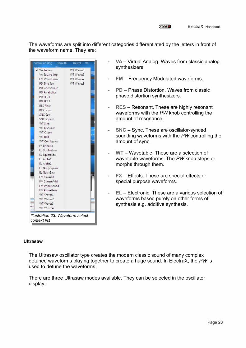
The waveforms are split into different categories differentiated by the letters in front of the waveform name. They are:
• VA – Virtual Analog. Waves from classic analog synthesizers.
• FM – Frequency Modulated waveforms.
• PD – Phase Distortion. Waves from classic phase distortion synthesizers.
• RES – Resonant. These are highly resonant waveforms with the PW knob controlling the amount of resonance.
• SNC – Sync. These are oscillator-synced sounding waveforms with the PW controlling the amount of sync.
• WT – Wavetable. These are a selection of wavetable waveforms. The PW knob steps or morphs through them.
• FX – Effects. These are special effects or special purpose waveforms.
• EL – Electronic. These are a various selection of waveforms based purely on other forms of synthesis e.g. additive synthesis.
Ultrasaw
The Ultrasaw oscillator type creates the modern classic sound of many complex detuned waveforms playing together to create a huge sound. In ElectraX, the PW is used to detune the waveforms.
There are three Ultrasaw modes available. They can be selected in the oscillator display:
Page 28
Illustration 23: Waveform select context list
ElectraX Handbook
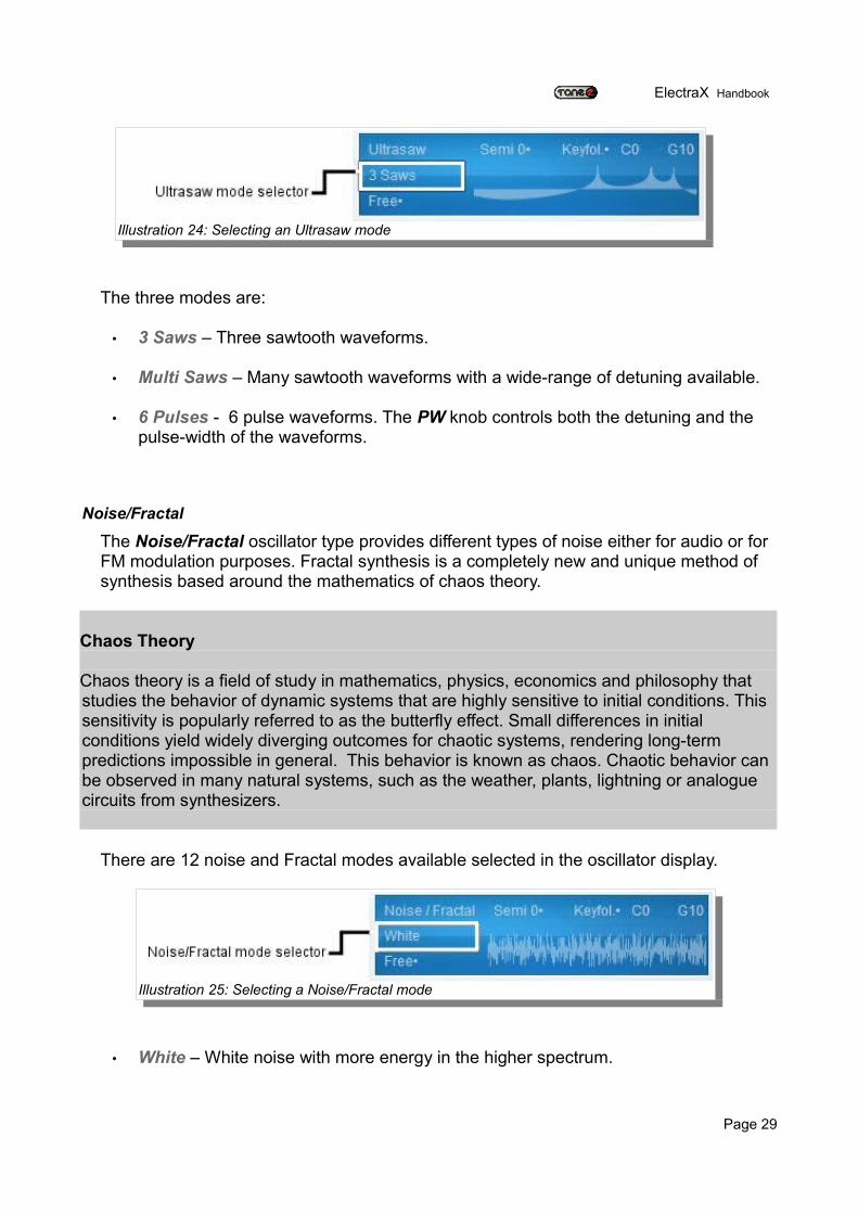
The three modes are:
• 3 Saws – Three sawtooth waveforms.
• Multi Saws – Many sawtooth waveforms with a wide-range of detuning available.
• 6 Pulses - 6 pulse waveforms. The PW knob controls both the detuning and the pulse-width of the waveforms.
Noise/Fractal
The Noise/Fractal oscillator type provides different types of noise either for audio or for FM modulation purposes. Fractal synthesis is a completely new and unique method of synthesis based around the mathematics of chaos theory.
Chaos Theory
Chaos theory is a field of study in mathematics, physics, economics and philosophy that studies the behavior of dynamic systems that are highly sensitive to initial conditions. This sensitivity is popularly referred to as the butterfly effect. Small differences in initial conditions yield widely diverging outcomes for chaotic systems, rendering long-term predictions impossible in general. This behavior is known as chaos. Chaotic behavior can be observed in many natural systems, such as the weather, plants, lightning or analogue circuits from synthesizers.
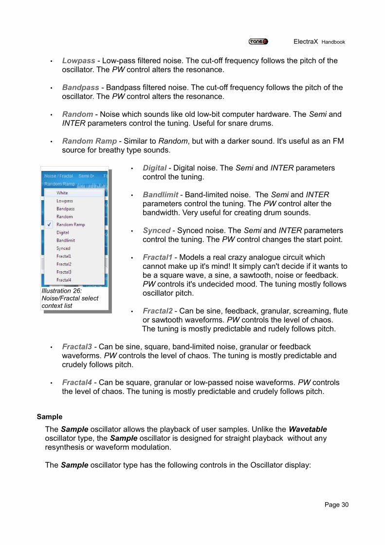
There are 12 noise and Fractal modes available selected in the oscillator display.
• White – White noise with more energy in the higher spectrum.
Page 29
Illustration 24: Selecting an Ultrasaw mode
Illustration 25: Selecting a Noise/Fractal mode
ElectraX Handbook
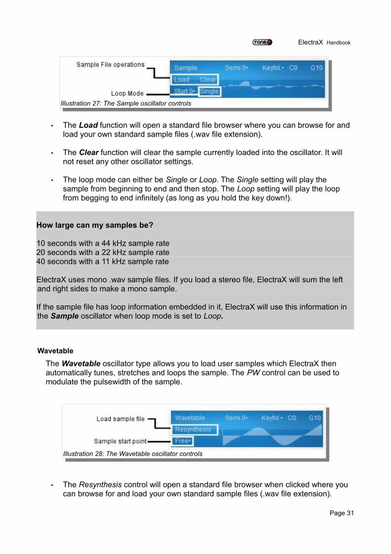
• Lowpass - Low-pass filtered noise. The cut-off frequency follows the pitch of the oscillator. The PW control alters the resonance.
• Bandpass - Bandpass filtered noise. The cut-off frequency follows the pitch of the oscillator. The PW control alters the resonance.
• Random - Noise which sounds like old low-bit computer hardware. The Semi and INTER parameters control the tuning. Useful for snare drums.
• Random Ramp - Similar to Random, but with a darker sound. It's useful as an FM source for breathy type sounds.
• Digital - Digital noise. The Semi and INTER parameters control the tuning.
• Bandlimit - Band-limited noise. The Semi and INTER parameters control the tuning. The PW control alter the bandwidth. Very useful for creating drum sounds.
• Synced - Synced noise. The Semi and INTER parameters control the tuning. The PW control changes the start point.
• Fractal1 - Models a real crazy analogue circuit which cannot make up it's mind! It simply can't decide if it wants to be a square wave, a sine, a sawtooth, noise or feedback. PW controls it's undecided mood. The tuning mostly follows oscillator pitch.
• Fractal2 - Can be sine, feedback, granular, screaming, flute or sawtooth waveforms. PW controls the level of chaos.
The tuning is mostly predictable and rudely follows pitch.
• Fractal3 - Can be sine, square, band-limited noise, granular or feedback waveforms. PW controls the level of chaos. The tuning is mostly predictable and crudely follows pitch.
• Fractal4 - Can be square, granular or low-passed noise waveforms. PW controls the level of chaos. The tuning is mostly predictable and crudely follows pitch.
Sample
The Sample oscillator allows the playback of user samples. Unlike the Wavetable oscillator type, the Sample oscillator is designed for straight playback without any resynthesis or waveform modulation.
The Sample oscillator type has the following controls in the Oscillator display:
Page 30
Illustration 26: Noise/Fractal select context list
ElectraX Handbook
• The Load function will open a standard file browser where you can browse for and load your own standard sample files (.wav file extension).
• The Clear function will clear the sample currently loaded into the oscillator. It will not reset any other oscillator settings.
• The loop mode can either be Single or Loop. The Single setting will play the sample from beginning to end and then stop. The Loop setting will play the loop from begging to end infinitely (as long as you hold the key down!).
How large can my samples be?
10 seconds with a 44 kHz sample rate20 seconds with a 22 kHz sample rate40 seconds with a 11 kHz sample rate
ElectraX uses mono .wav sample files. If you load a stereo file, ElectraX will sum the left and right sides to make a mono sample.
If the sample file has loop information embedded in it, ElectraX will use this information in the Sample oscillator when loop mode is set to Loop.
Wavetable
The Wavetable oscillator type allows you to load user samples which ElectraX then automatically tunes, stretches and loops the sample. The PW control can be used to modulate the pulsewidth of the sample.
• The Resynthesis control will open a standard file browser when clicked where you can browse for and load your own standard sample files (.wav file extension).
Page 31
Illustration 27: The Sample oscillator controls
Illustration 28: The Wavetable oscillator controls
ElectraX Handbook
More on ElectraX’s resynthesis
How ElectraX resynthesizes your sample depends on the size of the sample file.
File with less than 4096 samples:
ElectraX will treat these sample files as a single cycle waveform and will automatically, stretch and loop it.You can use the PW control to change the pulse-width of the waveform.
File with 4096 samples or more:
ElectraX will automatically tune, stretch and loop the sample. It will then resynthesize a custom waveform from the middle section of the sound. You can use the PW control to change the pulse-width of the waveform.
• Start - The start point control changes the start phase of the resynthesized waveform so that, depending on the sampled sound, can drastically change the character of the waveform. A setting of Free will cause the phase to be randomly changed every time a note is played.
Key controls
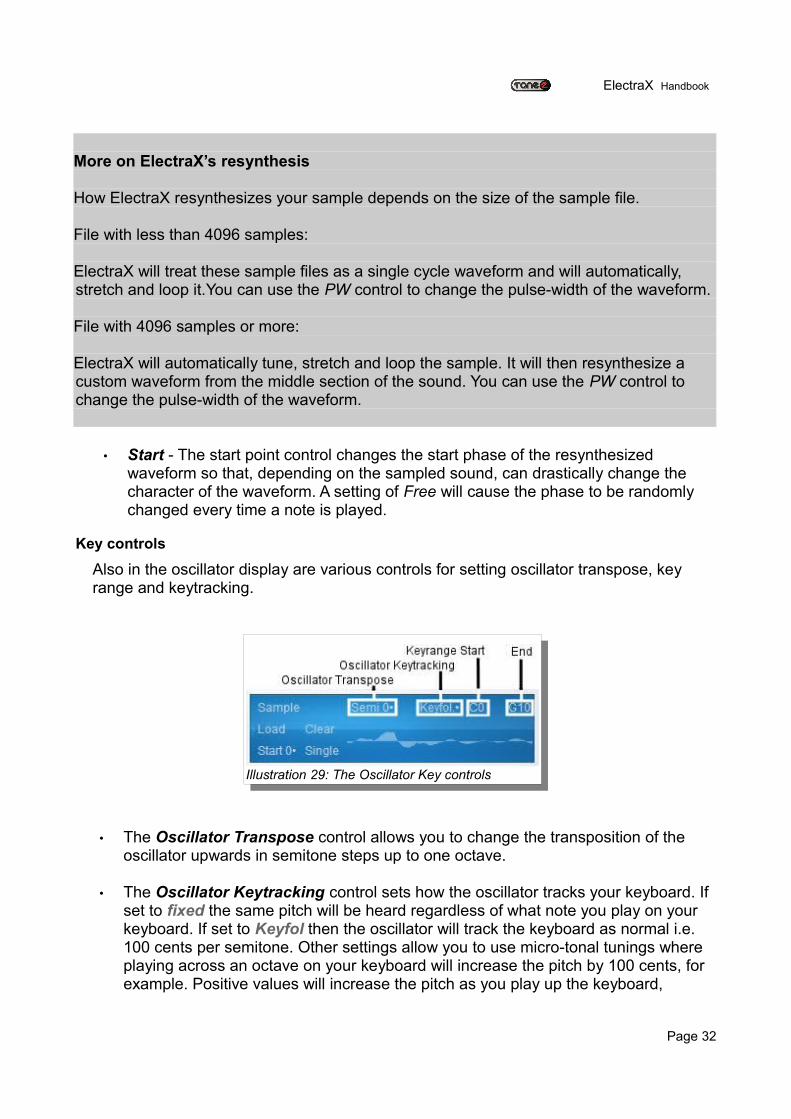
Also in the oscillator display are various controls for setting oscillator transpose, key range and keytracking.
• The Oscillator Transpose control allows you to change the transposition of the oscillator upwards in semitone steps up to one octave.
• The Oscillator Keytracking control sets how the oscillator tracks your keyboard. If set to fixed the same pitch will be heard regardless of what note you play on your keyboard. If set to Keyfol then the oscillator will track the keyboard as normal i.e. 100 cents per semitone. Other settings allow you to use micro-tonal tunings where playing across an octave on your keyboard will increase the pitch by 100 cents, for example. Positive values will increase the pitch as you play up the keyboard,
Page 32
Illustration 29: The Oscillator Key controls
ElectraX Handbook
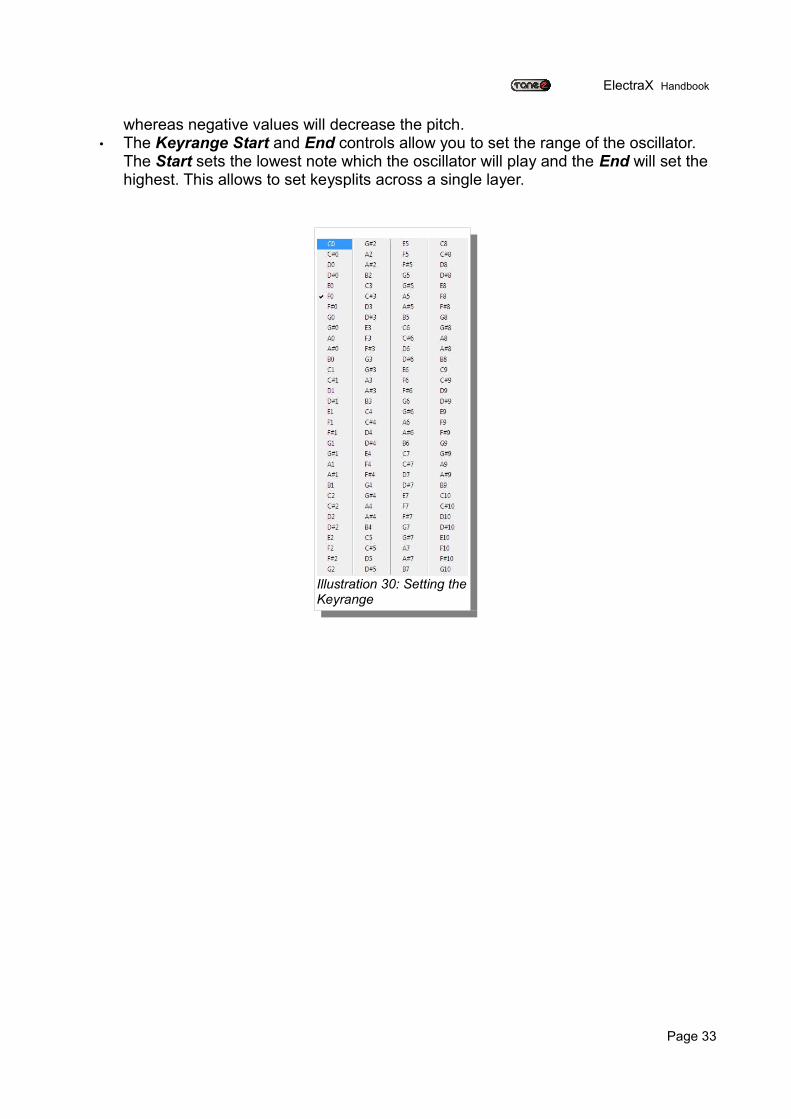
whereas negative values will decrease the pitch. • The Keyrange Start and End controls allow you to set the range of the oscillator.
The Start sets the lowest note which the oscillator will play and the End will set the highest. This allows to set keysplits across a single layer.
Page 33
Illustration 30: Setting the Keyrange
ElectraX Handbook
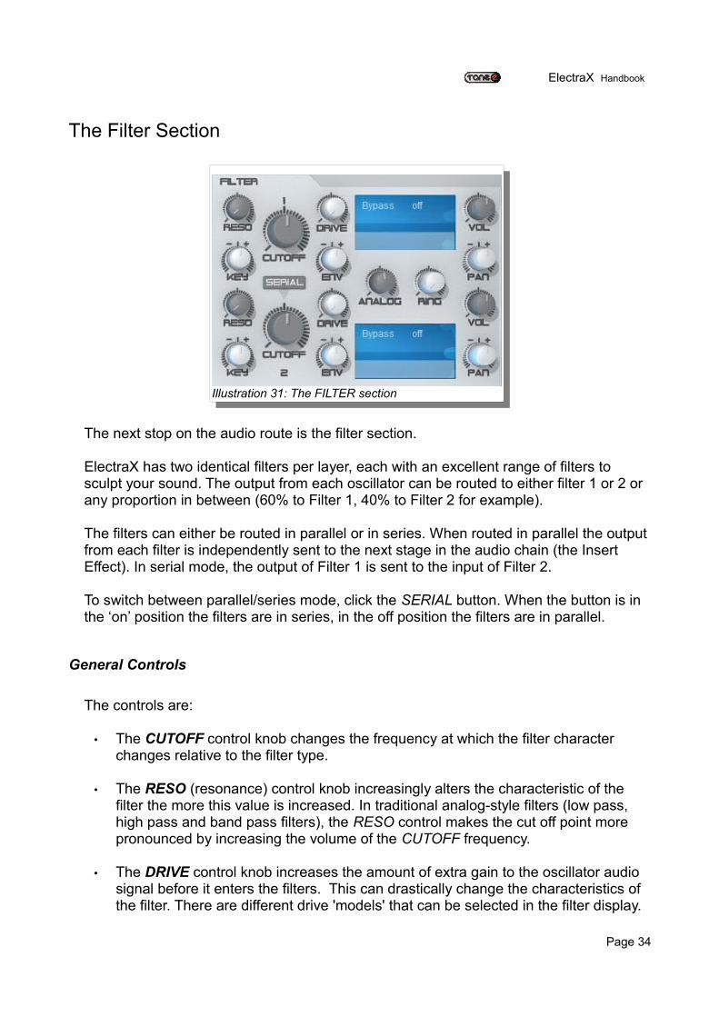
The Filter Section
The next stop on the audio route is the filter section.
ElectraX has two identical filters per layer, each with an excellent range of filters to sculpt your sound. The output from each oscillator can be routed to either filter 1 or 2 or any proportion in between (60% to Filter 1, 40% to Filter 2 for example).
The filters can either be routed in parallel or in series. When routed in parallel the output from each filter is independently sent to the next stage in the audio chain (the Insert Effect). In serial mode, the output of Filter 1 is sent to the input of Filter 2.
To switch between parallel/series mode, click the SERIAL button. When the button is in the ‘on’ position the filters are in series, in the off position the filters are in parallel.
General Controls
The controls are:
• The CUTOFF control knob changes the frequency at which the filter character changes relative to the filter type.
• The RESO (resonance) control knob increasingly alters the characteristic of the filter the more this value is increased. In traditional analog-style filters (low pass, high pass and band pass filters), the RESO control makes the cut off point more pronounced by increasing the volume of the CUTOFF frequency.
• The DRIVE control knob increases the amount of extra gain to the oscillator audio signal before it enters the filters. This can drastically change the characteristics of the filter. There are different drive 'models' that can be selected in the filter display.
Page 34
Illustration 31: The FILTER section
ElectraX Handbook
• The KEY knob is a bi-polar control that determines how the note played on the keyboard affects the filter cut off frequency. At positive values above 0, higher note values will increase the cut off frequency. At negative values below 0, higher note values will decrease the cut off frequency.
• The ENV control knob is also bi-polar that determines how much influence the filter envelope has on the CUTOFF control and in which direction. Positive values over 0 will increase the filter cut off value as the envelope outputs a positive value. Negative values under 0 will decrease the cut off value as the envelope outputs a positive value.
The Filter and the Envelope
Remember that as you increase the ENV control you’ll probably need to turn down the CUTOFF otherwise you won’t hear much of the envelope affecting the cut off. However, you’ll need to increase the CUTOFF if you want to use negative ENV amounts
• The ANALOG knob controls how much of the circuit-modelled characteristics of hardware analog filters are added to the current filter.
• The RING knob controls the amount of ring modulation on the filter outputs.
The Ring Modulator
The ring modulator gets it’s name from the ring of four diodes in the original modulator circuit. The ring modulator makes a sound from
The VOL knob controls the output volume of the filter. The PAN control knob places the filter's audio output in the stereo field. Turning the knob to the left moves the sound to the left. Likewise turning the knob to the right moves the sound to the right.
The Filter Display
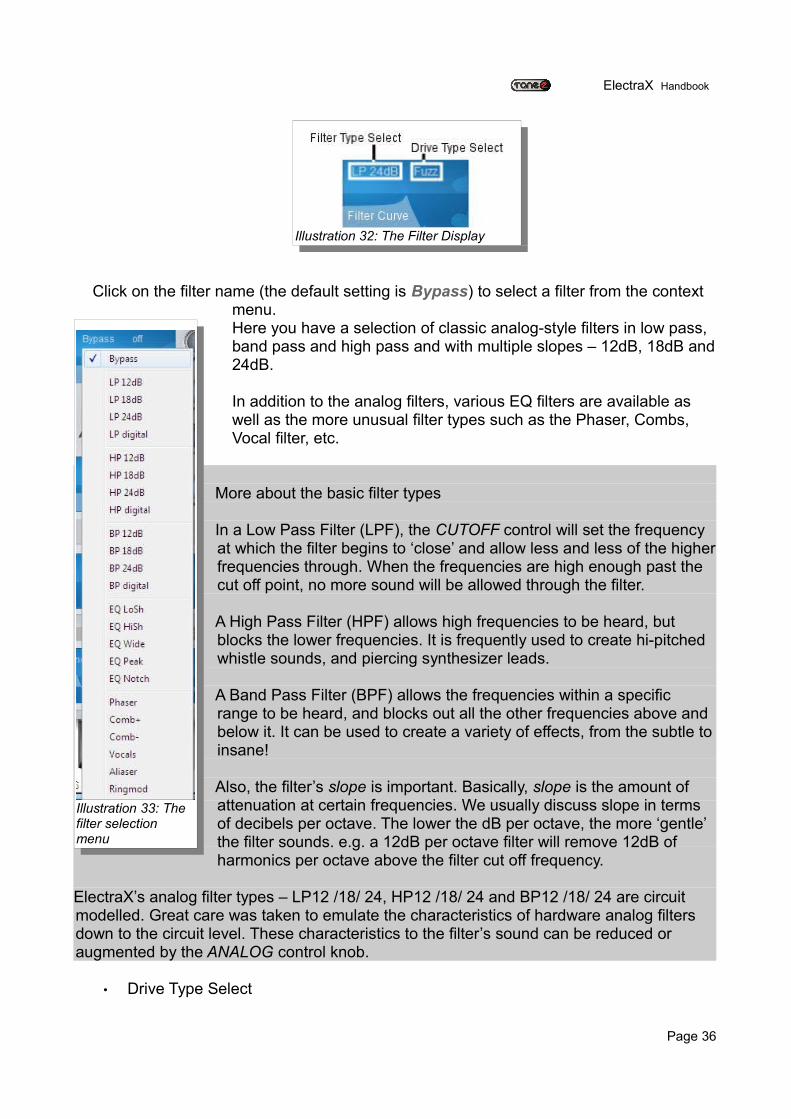
Each filter has it’s own filter display that has the dual purpose of selecting parameters and shows the real time shaping of the filter as you alter the CUTOFF and RESO parameters. The horizontal axis show frequencies from lowest to highest, while the vertical axis represents the gain. This really innovative feature from ElectraX gives you immediate visual feedback on your actions and helps you to learn about the specifics of each of ElectraX’s first class and versatile filters.
• Filter Type Select
Page 35
ElectraX Handbook
Click on the filter name (the default setting is Bypass) to select a filter from the context menu.Here you have a selection of classic analog-style filters in low pass, band pass and high pass and with multiple slopes – 12dB, 18dB and 24dB.
In addition to the analog filters, various EQ filters are available as well as the more unusual filter types such as the Phaser, Combs, Vocal filter, etc.
More about the basic filter types
In a Low Pass Filter (LPF), the CUTOFF control will set the frequency at which the filter begins to ‘close’ and allow less and less of the higher frequencies through. When the frequencies are high enough past the cut off point, no more sound will be allowed through the filter.
A High Pass Filter (HPF) allows high frequencies to be heard, but blocks the lower frequencies. It is frequently used to create hi-pitched whistle sounds, and piercing synthesizer leads.
A Band Pass Filter (BPF) allows the frequencies within a specific range to be heard, and blocks out all the other frequencies above and below it. It can be used to create a variety of effects, from the subtle to insane!
Also, the filter’s slope is important. Basically, slope is the amount of attenuation at certain frequencies. We usually discuss slope in terms of decibels per octave. The lower the dB per octave, the more ‘gentle’ the filter sounds. e.g. a 12dB per octave filter will remove 12dB of harmonics per octave above the filter cut off frequency.
ElectraX’s analog filter types – LP12 /18/ 24, HP12 /18/ 24 and BP12 /18/ 24 are circuit modelled. Great care was taken to emulate the characteristics of hardware analog filters down to the circuit level. These characteristics to the filter’s sound can be reduced or augmented by the ANALOG control knob.
• Drive Type Select
Page 36
Illustration 32: The Filter Display
Illustration 33: The filter selection menu
ElectraX Handbook
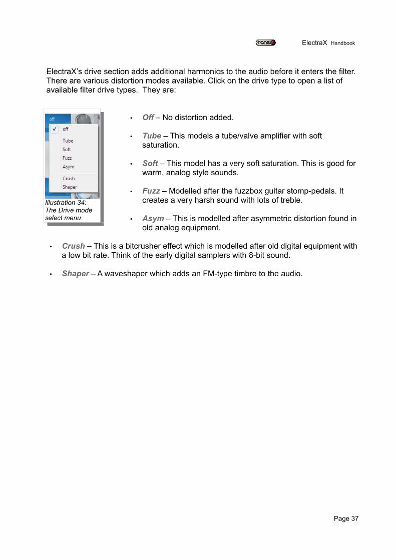
ElectraX’s drive section adds additional harmonics to the audio before it enters the filter. There are various distortion modes available. Click on the drive type to open a list of available filter drive types. They are:
• Off – No distortion added.
• Tube – This models a tube/valve amplifier with soft saturation.
• Soft – This model has a very soft saturation. This is good for warm, analog style sounds.
• Fuzz – Modelled after the fuzzbox guitar stomp-pedals. It creates a very harsh sound with lots of treble.
• Asym – This is modelled after asymmetric distortion found in old analog equipment.
• Crush – This is a bitcrusher effect which is modelled after old digital equipment with a low bit rate. Think of the early digital samplers with 8-bit sound.
• Shaper – A waveshaper which adds an FM-type timbre to the audio.
Page 37
Illustration 34: The Drive mode select menu
ElectraX Handbook
The Insert Effect Section
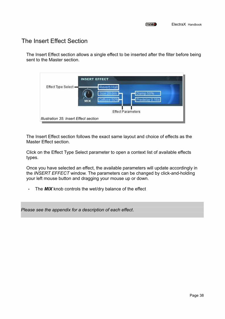
The Insert Effect section allows a single effect to be inserted after the filter before being sent to the Master section.
The Insert Effect section follows the exact same layout and choice of effects as the Master Effect section.
Click on the Effect Type Select parameter to open a context list of available effects types.
Once you have selected an effect, the available parameters will update accordingly in the INSERT EFFECT window. The parameters can be changed by click-and-holding your left mouse button and dragging your mouse up or down.
• The MIX knob controls the wet/dry balance of the effect
Please see the appendix for a description of each effect.
Page 38
Illustration 35: Insert Effect section
ElectraX Handbook
The Settings Section
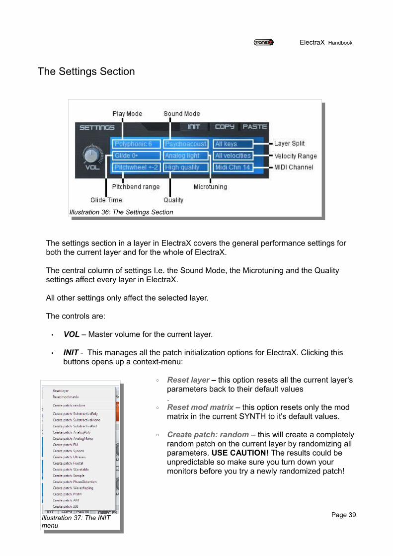
The settings section in a layer in ElectraX covers the general performance settings for both the current layer and for the whole of ElectraX.
The central column of settings I.e. the Sound Mode, the Microtuning and the Quality settings affect every layer in ElectraX.
All other settings only affect the selected layer.
The controls are:
• VOL – Master volume for the current layer.
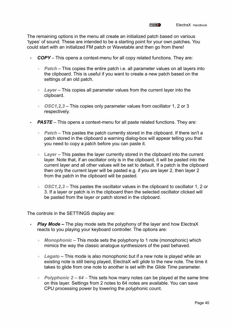
• INIT - This manages all the patch initialization options for ElectraX. Clicking this buttons opens up a context-menu:
◦ Reset layer – this option resets all the current layer's parameters back to their default values.
◦ Reset mod matrix – this option resets only the mod matrix in the current SYNTH to it's default values.
◦ Create patch: random – this will create a completely random patch on the current layer by randomizing all parameters. USE CAUTION! The results could be unpredictable so make sure you turn down your monitors before you try a newly randomized patch!
Page 39
Illustration 36: The Settings Section
Illustration 37: The INIT menu
ElectraX Handbook
The remaining options in the menu all create an initialized patch based on various ‘types’ of sound. These are intended to be a starting point for your own patches. You could start with an initialized FM patch or Wavetable and then go from there!
• COPY – This opens a context-menu for all copy related functions. They are: ◦ Patch – This copies the entire patch i.e. all parameter values on all layers into
the clipboard. This is useful if you want to create a new patch based on the settings of an old patch.
◦ Layer – This copies all parameter values from the current layer into the clipboard.
◦ OSC1,2,3 – This copies only parameter values from oscillator 1, 2 or 3 respectively.
• PASTE – This opens a context-menu for all paste related functions. They are:
◦ Patch – This pastes the patch currently stored in the clipboard. If there isn't a patch stored in the clipboard a warning dialog-box will appear telling you that you need to copy a patch before you can paste it.
◦ Layer – This pastes the layer currently stored in the clipboard into the current layer. Note that, if an oscillator only is in the clipboard, it will be pasted into the current layer and all other values will be set to default. If a patch is the clipboard then only the current layer will be pasted e.g. if you are layer 2, then layer 2 from the patch in the clipboard will be pasted.
◦ OSC1,2,3 – This pastes the oscillator values in the clipboard to oscillator 1, 2 or 3. If a layer or patch is in the clipboard then the selected oscillator clicked will be pasted from the layer or patch stored in the clipboard.
The controls in the SETTINGS display are:
• Play Mode – The play mode sets the polyphony of the layer and how ElectraX reacts to you playing your keyboard controller. The options are:
◦ Monophonic – This mode sets the polyphony to 1 note (monophonic) which mimics the way the classic analogue synthesizers of the past behaved.
◦ Legato – This mode is also monophonic but if a new note is played while an existing note is still being played, ElectraX will glide to the new note. The time it takes to glide from one note to another is set with the Glide Time parameter.
◦ Polyphonic 2 – 64 – This sets how many notes can be played at the same time on this layer. Settings from 2 notes to 64 notes are available. You can save CPU processing power by lowering the polyphonic count.
Page 40
ElectraX Handbook
• Glide Time - Also called 'Portamento', this will set how long it will take for one note to 'glide' or 'slide' to another. A setting of '0' (default) means that the glide function is turned off.
• Pitchwheel Range – This will set how many semitones the pitchwheel on your keyboard controller will transpose up or down. +-2 means that the pitchwheel will transpose the pitch up or down two semitones. +-12 is one octave and +-24 is two octaves.
• Sound Mode – The Sound Mode sets the overall sound 'character' of ElectraX. The options are: ◦ Linear sound – This mode has a 'technically perfect' linear frequency and
phase response.
◦ Psychoacoust. - This mode molds the frequency and phase response to mimic the behaviour of the human ear.
◦ Analog sound – This mimics the character of analog synths, with a warmer sound and beefier bass.
◦ Bright sound – This mode also mimics the behavior of the human ear but with attenuated bass to create a brighter sound.
What is Psychoacoustics?
Psychoacoustics is the study of the subjective human perception of sounds. Hearing is not a purely mechanical phenomenon of wave propagation, but is also a sensory and perceptual event. When a person hears something, that something arrives at the ear as a mechanical sound wave travelling through the air, but within the ear it is transformed into neural action potentials. These nerve pulses then travel to the brain where they are perceived. Hence, in many problems in acoustics, such as for audio processing, it is advantageous to take into account not just the mechanics of the environment, but also the fact that both the ear and the brain are involved in a person’s listening experience.
• Microtuning – This sets the how ElectraX is tuned. The options are:
◦ Well temp. - This is the standard Western 'Equal Temperament' scale.
◦ Analog light – This mode emulates a fairly 'stable' analog synthesizer with minimal tuning drift and circuit instabilities.
◦ Analog medium – This emulates an analog synthesizer with a greater amount of tuning drift and instability.
◦ Analog heavy – Similar to Analog light and medium but emulates an analog
Page 41
ElectraX Handbook
synth in need of repair! This mode emulates heave oscillator drift and instability.
◦ Fat tune 1, 2 - Fat tune makes chords sound 'fuller' and more 'fat' but at the same time they sound harmonically pure. Fat tune 2 has more of the effect than Fat tune 1.
◦ Just inton. - Just intonation. This is a musical tuning in which the frequencies of notes are related by ratios of small whole numbers. Bagpipes, when tuned correctly, uses a system of just intonation.
• Quality – This parameter sets the 'sound quality' of ElectraX. With computer-based digital synthesizers a compromise must usually be made between the best sound quality and the amount of CPU resources that it consumes. The better the sound quality, the more CPU resources it needs. The options are:
◦ Low CPU – This setting is the most CPU efficient mode but with a sacrifice of sound quality.
◦ High quality – This is the default setting. This gives the best sound quality but with a higher usage of CPU resources compare to Low CPU.
◦ Crossblend PW - This mode allows the smooth morphing or blending of waves in the wavetables if this effect is desired. This does use a higher amount of CPU resources so use with caution.
• Layer Split – This setting allows you to set up keyboard splits so that the layer only plays across a certain range of your keyboard controller. If different layers have different settings, you can set up bass/lead splits, for example. The settings are:
◦ All keys – This will allow you to play the entire range of your keyboard controller. This is the default setting.
◦ Split low – This splits the layer at key B2. Keys from B2 downwards can be played. All keys from C3 upwards will not play.
◦ Split high – This splits the layer at key C3. Keys from C3 upwards can be played. All keys from B3 downwards will not play.
◦ Octave 0-4 – This allows you to play from the bottom octave (octave 0) to octave 4. All other octaves will not play.
◦ Octave 5 – This option plays only octave 5.
◦ Octave 6 – This option plays only octave 6.
◦ Octave 7-10 – This will play the top four octaves.
Page 42
ElectraX Handbook
• Velocity Range – This sets the range of velocity in which the layer will play. Anything outside this range and this layer will not produce any sound. The options are: ◦ All velocities – This option will play the layer regardless of what velocity you
play your keyboard controller. This is the default option.
◦ The other options show a lower limit and a higher limit e.g. 64-128. The layer will play if the received velocity is between these two values.
• MIDI Channel – This sets the MIDI channel for the layer. ElectraX will play if it receives MIDI information on this channel, all other channels it will ignore. The default value is 'All Channels' which means that the layer will play MIDI received on any channel.
The Arpeggiator Section
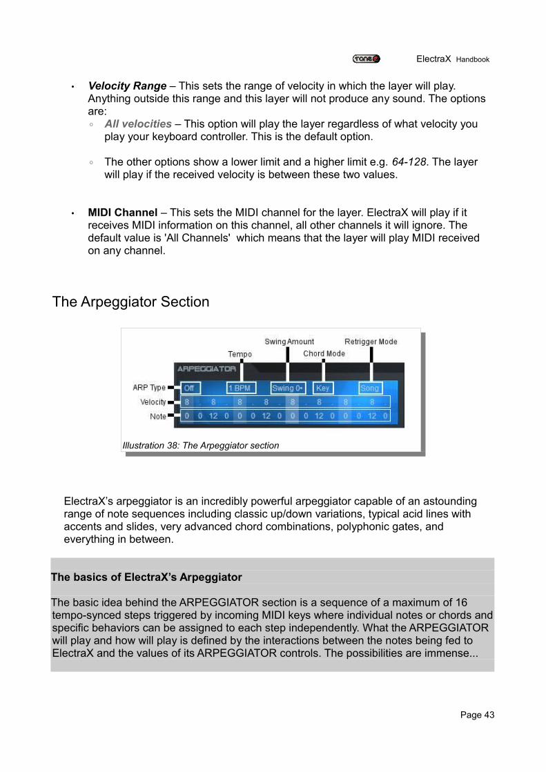
ElectraX’s arpeggiator is an incredibly powerful arpeggiator capable of an astounding range of note sequences including classic up/down variations, typical acid lines with accents and slides, very advanced chord combinations, polyphonic gates, and everything in between.
The basics of ElectraX’s Arpeggiator
The basic idea behind the ARPEGGIATOR section is a sequence of a maximum of 16 tempo-synced steps triggered by incoming MIDI keys where individual notes or chords and specific behaviors can be assigned to each step independently. What the ARPEGGIATOR will play and how will play is defined by the interactions between the notes being fed to ElectraX and the values of its ARPEGGIATOR controls. The possibilities are immense...
Page 43
Illustration 38: The Arpeggiator section
ElectraX Handbook
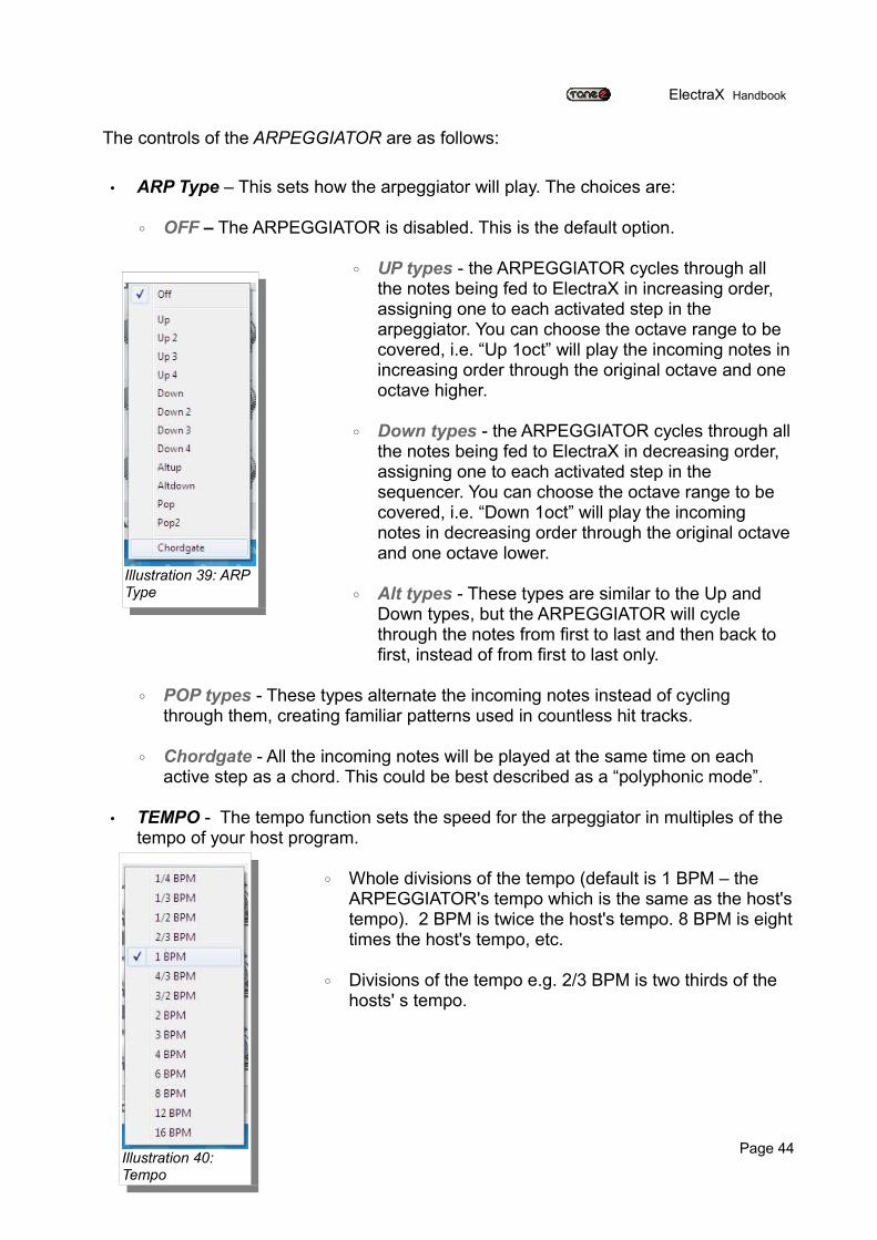
The controls of the ARPEGGIATOR are as follows:
• ARP Type – This sets how the arpeggiator will play. The choices are:
◦ OFF – The ARPEGGIATOR is disabled. This is the default option.
◦ UP types - the ARPEGGIATOR cycles through all the notes being fed to ElectraX in increasing order, assigning one to each activated step in the arpeggiator. You can choose the octave range to be covered, i.e. “Up 1oct” will play the incoming notes in increasing order through the original octave and one octave higher.
◦ Down types - the ARPEGGIATOR cycles through all the notes being fed to ElectraX in decreasing order, assigning one to each activated step in the sequencer. You can choose the octave range to be covered, i.e. “Down 1oct” will play the incoming notes in decreasing order through the original octave and one octave lower.
◦ Alt types - These types are similar to the Up and Down types, but the ARPEGGIATOR will cycle through the notes from first to last and then back to first, instead of from first to last only.
◦ POP types - These types alternate the incoming notes instead of cycling through them, creating familiar patterns used in countless hit tracks.
◦ Chordgate - All the incoming notes will be played at the same time on each active step as a chord. This could be best described as a “polyphonic mode”.
• TEMPO - The tempo function sets the speed for the arpeggiator in multiples of the tempo of your host program.
◦ Whole divisions of the tempo (default is 1 BPM – the ARPEGGIATOR's tempo which is the same as the host's tempo). 2 BPM is twice the host's tempo. 8 BPM is eight times the host's tempo, etc.
◦ Divisions of the tempo e.g. 2/3 BPM is two thirds of the hosts' s tempo.
Page 44
Illustration 39: ARP Type
Illustration 40: Tempo
ElectraX Handbook
• Swing Amount – To create a more 'human' feel to the arpeggiator, you can increase the amount of 'swing' from 0 (no swing) to 99 (full swing). The swing feature alternately delays and rushes the arpeggiator steps to add feel.
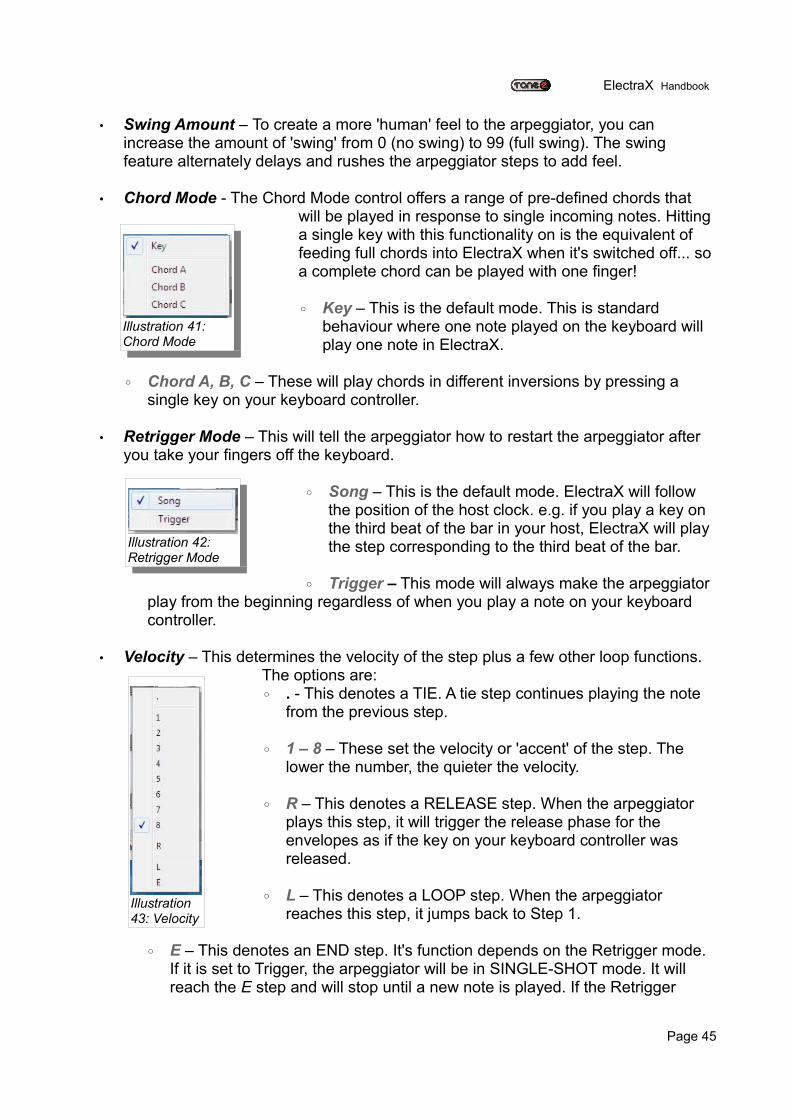
• Chord Mode - The Chord Mode control offers a range of pre-defined chords that will be played in response to single incoming notes. Hitting a single key with this functionality on is the equivalent of feeding full chords into ElectraX when it's switched off... so a complete chord can be played with one finger!
◦ Key – This is the default mode. This is standard behaviour where one note played on the keyboard will play one note in ElectraX.
◦ Chord A, B, C – These will play chords in different inversions by pressing a single key on your keyboard controller.
• Retrigger Mode – This will tell the arpeggiator how to restart the arpeggiator after you take your fingers off the keyboard.
◦ Song – This is the default mode. ElectraX will follow the position of the host clock. e.g. if you play a key on the third beat of the bar in your host, ElectraX will play the step corresponding to the third beat of the bar.
◦ Trigger – This mode will always make the arpeggiator play from the beginning regardless of when you play a note on your keyboard controller.
• Velocity – This determines the velocity of the step plus a few other loop functions. The options are: ◦ . - This denotes a TIE. A tie step continues playing the note
from the previous step.
◦ 1 – 8 – These set the velocity or 'accent' of the step. The lower the number, the quieter the velocity.
◦ R – This denotes a RELEASE step. When the arpeggiator plays this step, it will trigger the release phase for the envelopes as if the key on your keyboard controller was released.
◦ L – This denotes a LOOP step. When the arpeggiator reaches this step, it jumps back to Step 1.
◦ E – This denotes an END step. It's function depends on the Retrigger mode. If it is set to Trigger, the arpeggiator will be in SINGLE-SHOT mode. It will reach the E step and will stop until a new note is played. If the Retrigger
Page 45
Illustration 41: Chord Mode
Illustration 42: Retrigger Mode
Illustration 43: Velocity
ElectraX Handbook
mode is set to Song the E step will behave the same as a LOOP step.
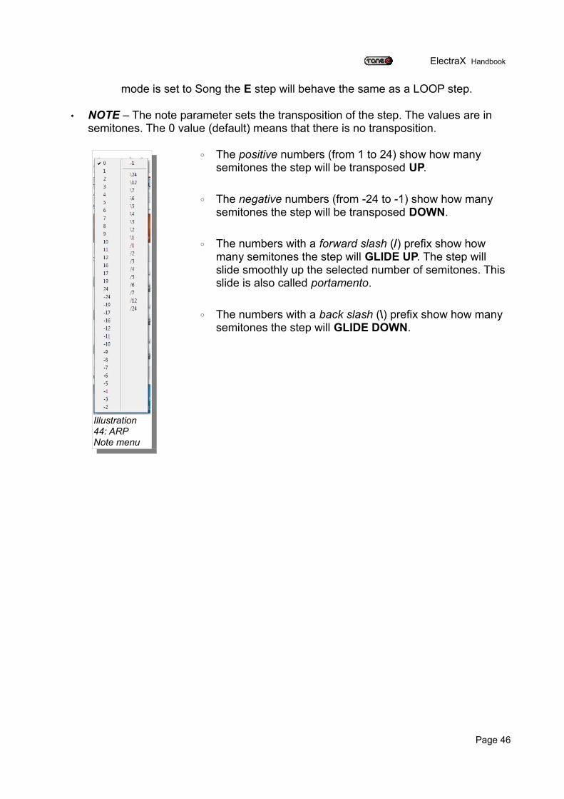
• NOTE – The note parameter sets the transposition of the step. The values are in semitones. The 0 value (default) means that there is no transposition.
◦ The positive numbers (from 1 to 24) show how many semitones the step will be transposed UP.
◦ The negative numbers (from -24 to -1) show how many semitones the step will be transposed DOWN.
◦ The numbers with a forward slash (/) prefix show how many semitones the step will GLIDE UP. The step will slide smoothly up the selected number of semitones. This slide is also called portamento.
◦ The numbers with a back slash (\) prefix show how many semitones the step will GLIDE DOWN.
Page 46
Illustration 44: ARP Note menu
ElectraX Handbook
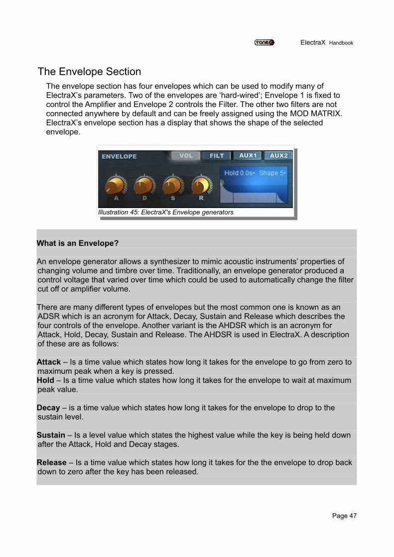
The Envelope SectionThe envelope section has four envelopes which can be used to modify many of ElectraX’s parameters. Two of the envelopes are ‘hard-wired’; Envelope 1 is fixed to control the Amplifier and Envelope 2 controls the Filter. The other two filters are not connected anywhere by default and can be freely assigned using the MOD MATRIX. ElectraX’s envelope section has a display that shows the shape of the selected envelope.
What is an Envelope?
An envelope generator allows a synthesizer to mimic acoustic instruments’ properties of changing volume and timbre over time. Traditionally, an envelope generator produced a control voltage that varied over time which could be used to automatically change the filter cut off or amplifier volume.
There are many different types of envelopes but the most common one is known as an ADSR which is an acronym for Attack, Decay, Sustain and Release which describes the four controls of the envelope. Another variant is the AHDSR which is an acronym for Attack, Hold, Decay, Sustain and Release. The AHDSR is used in ElectraX. A description of these are as follows:
Attack – Is a time value which states how long it takes for the envelope to go from zero to maximum peak when a key is pressed.Hold – Is a time value which states how long it takes for the envelope to wait at maximum peak value.
Decay – is a time value which states how long it takes for the envelope to drop to the sustain level.
Sustain – Is a level value which states the highest value while the key is being held down after the Attack, Hold and Decay stages.
Release – Is a time value which states how long it takes for the the envelope to drop back down to zero after the key has been released.
Page 47
Illustration 45: ElectraX's Envelope generators
ElectraX Handbook
The button controls are used to switch between the four different envelopes:
• VOL – This selects the envelope that controls the current layer's volume.
• FILT – This button selects the envelope that controls the current layer's filter cut off.
• AUX1 – This selects the Auxiliary 1 envelope which doesn't have a preset routing. It can be routed to many destinations using the MOD MATRIX.
• AUX2 – This selects the Auxiliary 2 envelope. Like AUX1, it doesn't have a preset routing. It can be routed using the MOD MATRIX,
The knob controls are used for the main envelope controls:
• A – This controls the Attack Time of the envelope. • D – This controls the Decay Time of the envelope. • S – This sets the level of the Sustain section. • R – This sets the Release Time of the envelope.
The display window controls are:
• Hold- This specifies the hold time of the envelope.
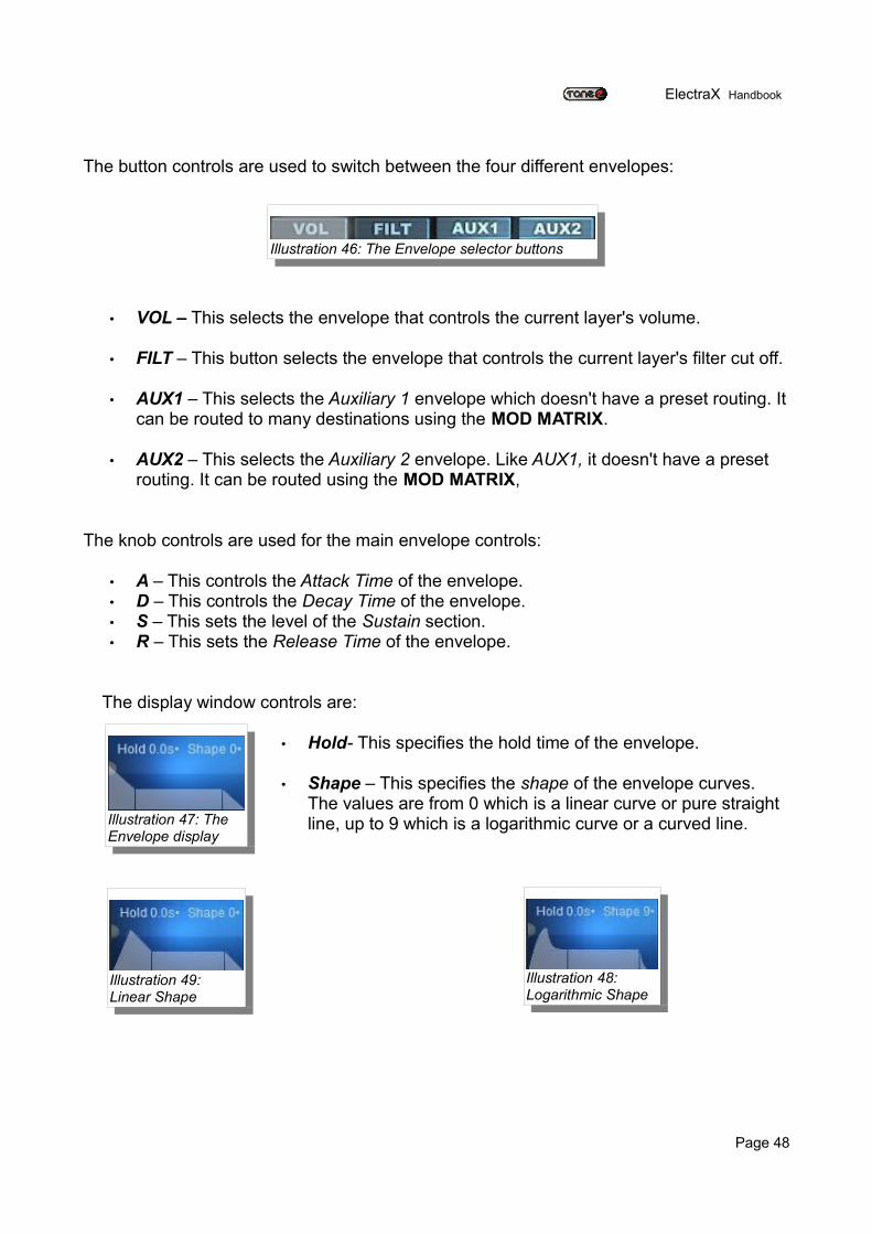
• Shape – This specifies the shape of the envelope curves. The values are from 0 which is a linear curve or pure straight line, up to 9 which is a logarithmic curve or a curved line.
Page 48
Illustration 46: The Envelope selector buttons
Illustration 49: Linear Shape
Illustration 48: Logarithmic Shape
Illustration 47: The Envelope display
ElectraX Handbook
The Mod Matrix Section
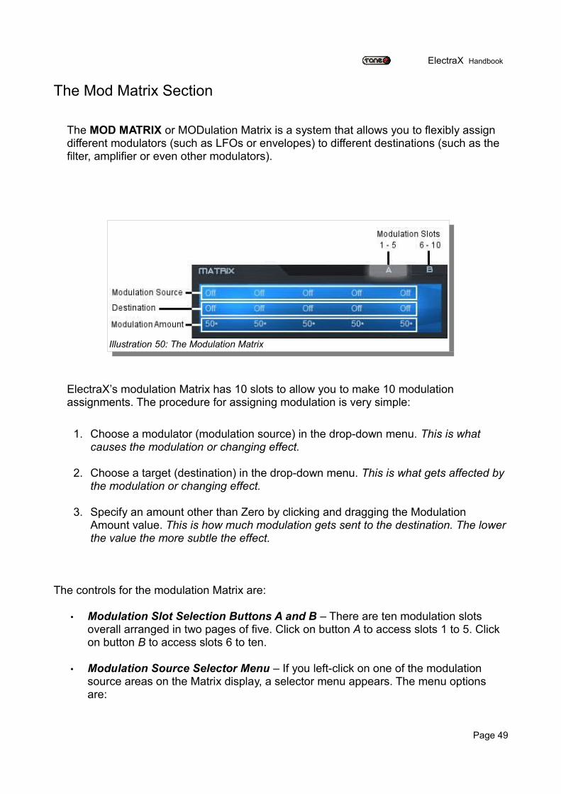
The MOD MATRIX or MODulation Matrix is a system that allows you to flexibly assign different modulators (such as LFOs or envelopes) to different destinations (such as the filter, amplifier or even other modulators).
ElectraX’s modulation Matrix has 10 slots to allow you to make 10 modulation assignments. The procedure for assigning modulation is very simple:
1. Choose a modulator (modulation source) in the drop-down menu. This is what causes the modulation or changing effect.
2. Choose a target (destination) in the drop-down menu. This is what gets affected by the modulation or changing effect.
3. Specify an amount other than Zero by clicking and dragging the Modulation Amount value. This is how much modulation gets sent to the destination. The lower the value the more subtle the effect.
The controls for the modulation Matrix are:
• Modulation Slot Selection Buttons A and B – There are ten modulation slots overall arranged in two pages of five. Click on button A to access slots 1 to 5. Click on button B to access slots 6 to ten.
• Modulation Source Selector Menu – If you left-click on one of the modulation source areas on the Matrix display, a selector menu appears. The menu options are:
Page 49
Illustration 50: The Modulation Matrix
ElectraX Handbook
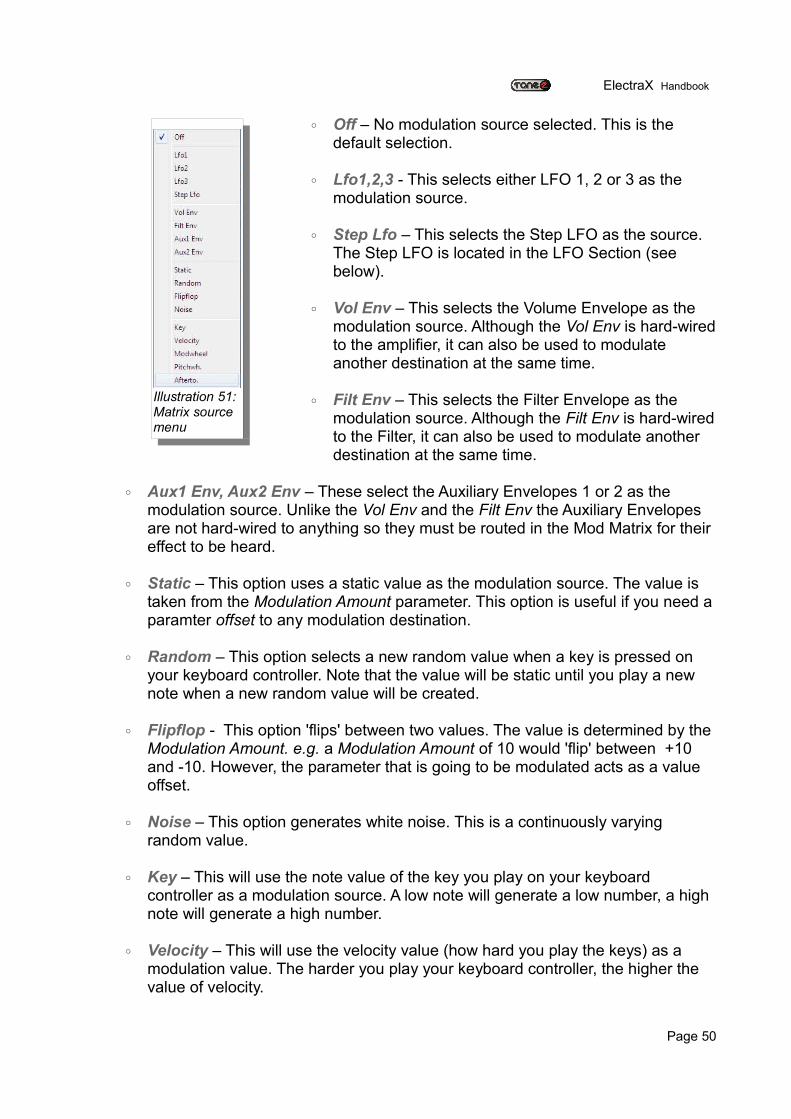
◦ Off – No modulation source selected. This is the default selection.
◦ Lfo1,2,3 - This selects either LFO 1, 2 or 3 as the modulation source.
◦ Step Lfo – This selects the Step LFO as the source. The Step LFO is located in the LFO Section (see below).
◦ Vol Env – This selects the Volume Envelope as the modulation source. Although the Vol Env is hard-wired to the amplifier, it can also be used to modulate another destination at the same time.
◦ Filt Env – This selects the Filter Envelope as the modulation source. Although the Filt Env is hard-wired to the Filter, it can also be used to modulate another destination at the same time.
◦ Aux1 Env, Aux2 Env – These select the Auxiliary Envelopes 1 or 2 as the modulation source. Unlike the Vol Env and the Filt Env the Auxiliary Envelopes are not hard-wired to anything so they must be routed in the Mod Matrix for their effect to be heard.
◦ Static – This option uses a static value as the modulation source. The value is taken from the Modulation Amount parameter. This option is useful if you need a paramter offset to any modulation destination.
◦ Random – This option selects a new random value when a key is pressed on your keyboard controller. Note that the value will be static until you play a new note when a new random value will be created.
◦ Flipflop - This option 'flips' between two values. The value is determined by the Modulation Amount. e.g. a Modulation Amount of 10 would 'flip' between +10 and -10. However, the parameter that is going to be modulated acts as a value offset.
◦ Noise – This option generates white noise. This is a continuously varying random value.
◦ Key – This will use the note value of the key you play on your keyboard controller as a modulation source. A low note will generate a low number, a high note will generate a high number.
◦ Velocity – This will use the velocity value (how hard you play the keys) as a modulation value. The harder you play your keyboard controller, the higher the value of velocity.
Page 50
Illustration 51: Matrix source menu
ElectraX Handbook
◦ Modwheel – This will use the modulation wheel from your keyboard controller as a modulation source. Note that you will only change the value if you move the modwheel, otherwise the value will be static (which will be the last value transmitted by the modwheel).
◦ Pitchwheel – This will use the pitchwheel from your keyboard controller as a modulation source.
◦ Afterto. - This will use the aftertouch messages from your keyboard controller as a modulation source. Please check the operating instructions of your keyboard controller to see if it generates aftertouch information. Not all keyboard controllers do.
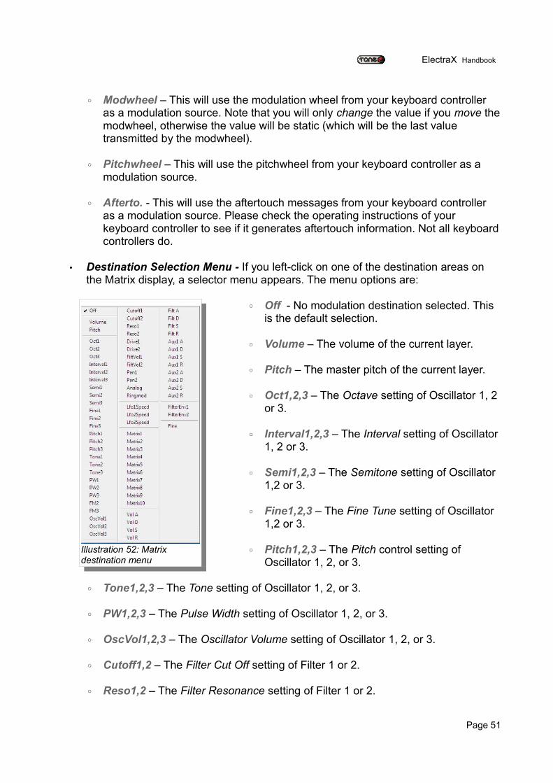
• Destination Selection Menu - If you left-click on one of the destination areas on the Matrix display, a selector menu appears. The menu options are:
◦ Off - No modulation destination selected. This is the default selection.
◦ Volume – The volume of the current layer.
◦ Pitch – The master pitch of the current layer.
◦ Oct1,2,3 – The Octave setting of Oscillator 1, 2 or 3.
◦ Interval1,2,3 – The Interval setting of Oscillator 1, 2 or 3.
◦ Semi1,2,3 – The Semitone setting of Oscillator 1,2 or 3.
◦ Fine1,2,3 – The Fine Tune setting of Oscillator 1,2 or 3.
◦ Pitch1,2,3 – The Pitch control setting of Oscillator 1, 2, or 3.
◦ Tone1,2,3 – The Tone setting of Oscillator 1, 2, or 3.
◦ PW1,2,3 – The Pulse Width setting of Oscillator 1, 2, or 3.
◦ OscVol1,2,3 – The Oscillator Volume setting of Oscillator 1, 2, or 3.
◦ Cutoff1,2 – The Filter Cut Off setting of Filter 1 or 2.
◦ Reso1,2 – The Filter Resonance setting of Filter 1 or 2.
Page 51
Illustration 52: Matrix destination menu
ElectraX Handbook
◦ Drive1,2 – The Filter Drive setting of Filter 1 or 2.
◦ FiltVol1, 2 – The Filter Volume setting of Filter 1 or 2.
◦ Pan1,2 – The Pan setting of Filter 1 or 2.
◦ Analog – The Analog setting in the Filter section.
◦ Ringmod – The Ringmod Amount setting in the Filter section.
◦ LFO1,2,3Speed – The Speed setting of LFO 1, 2, or 3.
◦ Matrix1,2,3,4,5,6,7,8,9,10 – The Modulation Amount setting of Modulation Matrix slot 1, 2, 3, 4, 5, 6, 7, 8, 9 or 10.
◦ Vol A,D,S,R – The Volume Envelope's Attack, Decay, Sustain or Release parameters.
◦ Filt A,D,S,R – The Filter Envelope's Attack, Decay, Sustain or Release parameters.
◦ Aux1 A,D,S,R – Auxiliary 1 Envelope's Attack, Decay, Sustain or Release parameters.
◦ Aux2 A,D,S,R – Auxiliary 2 Envelope's Attack, Decay, Sustain or Release parameters.
◦ FilterEnv1,2 – The Filter Envelope Amount setting in the Filter section.
◦ Fine – This is the master Fine control of the current layer.
• Modulation Amount – This is a bipolar control that ranges from -100 to 100. Click and drag the amount to change it. A positive number will give positive modulation and a negative number will give negative modulation.
Modulation Tips
You can use Modulation Amount as a destination if you wish to use one modulation source to control the amount of modulation of a parameter.
e.g. Use the Modwheel to control the amount of vibrato:
Page 52
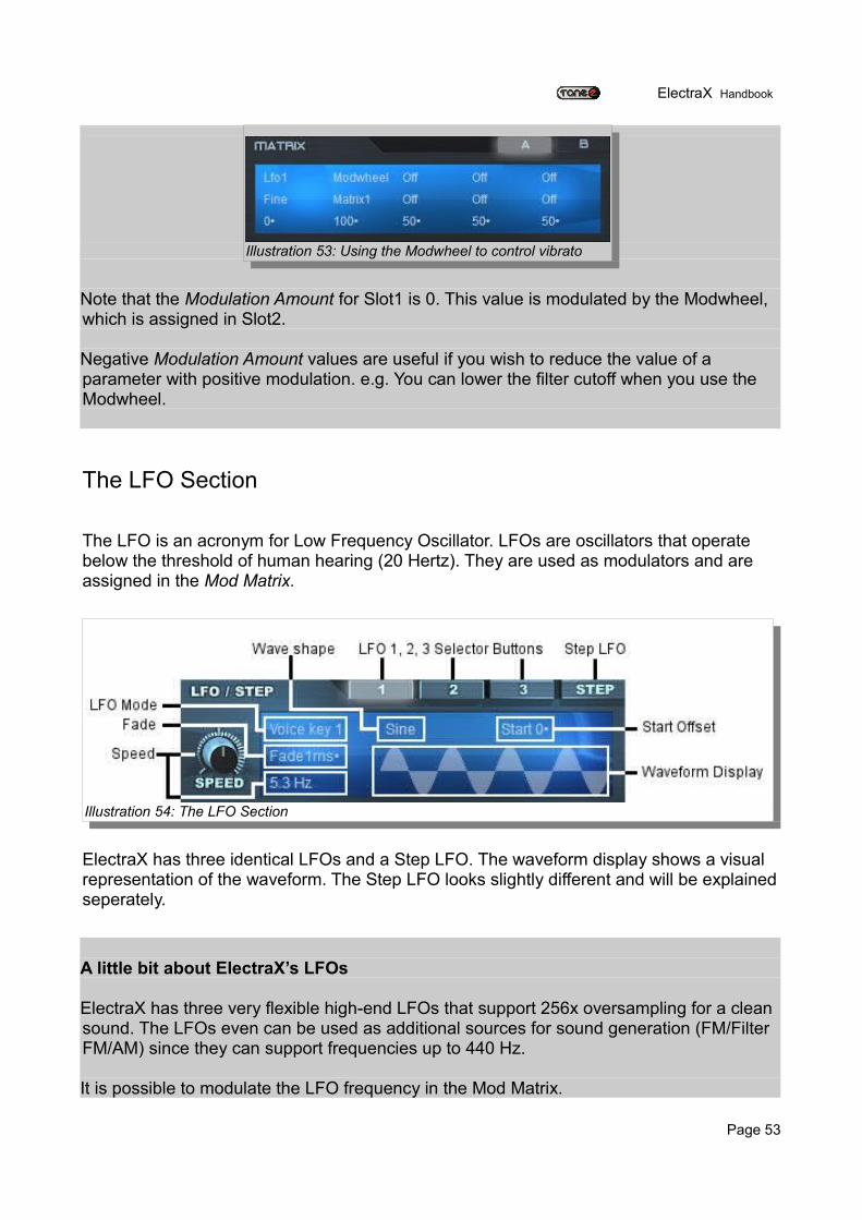
ElectraX Handbook
Note that the Modulation Amount for Slot1 is 0. This value is modulated by the Modwheel, which is assigned in Slot2.
Negative Modulation Amount values are useful if you wish to reduce the value of a parameter with positive modulation. e.g. You can lower the filter cutoff when you use the Modwheel.
The LFO Section
The LFO is an acronym for Low Frequency Oscillator. LFOs are oscillators that operate below the threshold of human hearing (20 Hertz). They are used as modulators and are assigned in the Mod Matrix.
ElectraX has three identical LFOs and a Step LFO. The waveform display shows a visual representation of the waveform. The Step LFO looks slightly different and will be explained seperately.
A little bit about ElectraX’s LFOs
ElectraX has three very flexible high-end LFOs that support 256x oversampling for a clean sound. The LFOs even can be used as additional sources for sound generation (FM/Filter FM/AM) since they can support frequencies up to 440 Hz.
It is possible to modulate the LFO frequency in the Mod Matrix.
Page 53
Illustration 53: Using the Modwheel to control vibrato
Illustration 54: The LFO Section
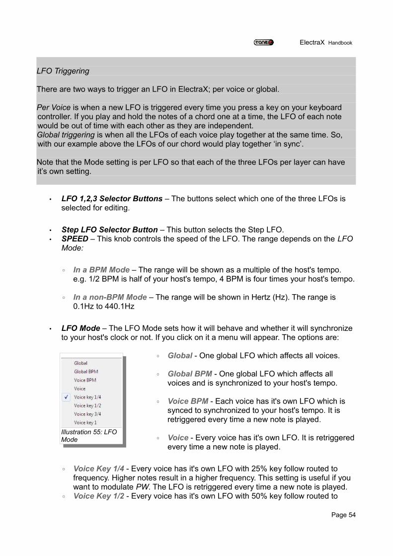
ElectraX Handbook
LFO Triggering
There are two ways to trigger an LFO in ElectraX; per voice or global.
Per Voice is when a new LFO is triggered every time you press a key on your keyboard controller. If you play and hold the notes of a chord one at a time, the LFO of each note would be out of time with each other as they are independent.Global triggering is when all the LFOs of each voice play together at the same time. So, with our example above the LFOs of our chord would play together ‘in sync’.
Note that the Mode setting is per LFO so that each of the three LFOs per layer can have it’s own setting.
• LFO 1,2,3 Selector Buttons – The buttons select which one of the three LFOs is selected for editing.
• Step LFO Selector Button – This button selects the Step LFO. • SPEED – This knob controls the speed of the LFO. The range depends on the LFO
Mode:
◦ In a BPM Mode – The range will be shown as a multiple of the host's tempo. e.g. 1/2 BPM is half of your host's tempo, 4 BPM is four times your host's tempo.
◦ In a non-BPM Mode – The range will be shown in Hertz (Hz). The range is 0.1Hz to 440.1Hz
• LFO Mode – The LFO Mode sets how it will behave and whether it will synchronize to your host's clock or not. If you click on it a menu will appear. The options are:
◦ Global - One global LFO which affects all voices.
◦ Global BPM - One global LFO which affects all voices and is synchronized to your host's tempo.
◦ Voice BPM - Each voice has it's own LFO which is synced to synchronized to your host's tempo. It is retriggered every time a new note is played.
◦ Voice - Every voice has it's own LFO. It is retriggered every time a new note is played.
◦ Voice Key 1/4 - Every voice has it's own LFO with 25% key follow routed to frequency. Higher notes result in a higher frequency. This setting is useful if you want to modulate PW. The LFO is retriggered every time a new note is played.
◦ Voice Key 1/2 - Every voice has it's own LFO with 50% key follow routed to
Page 54
Illustration 55: LFO Mode
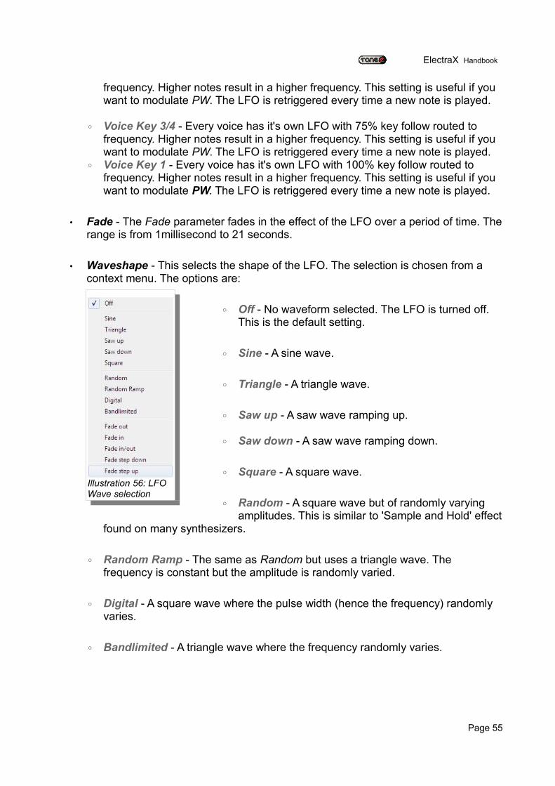
ElectraX Handbook
frequency. Higher notes result in a higher frequency. This setting is useful if you want to modulate PW. The LFO is retriggered every time a new note is played.
◦ Voice Key 3/4 - Every voice has it's own LFO with 75% key follow routed to frequency. Higher notes result in a higher frequency. This setting is useful if you want to modulate PW. The LFO is retriggered every time a new note is played.
◦ Voice Key 1 - Every voice has it's own LFO with 100% key follow routed to frequency. Higher notes result in a higher frequency. This setting is useful if you want to modulate PW. The LFO is retriggered every time a new note is played.
• Fade - The Fade parameter fades in the effect of the LFO over a period of time. The range is from 1millisecond to 21 seconds.
• Waveshape - This selects the shape of the LFO. The selection is chosen from a context menu. The options are:
◦ Off - No waveform selected. The LFO is turned off. This is the default setting.
◦ Sine - A sine wave.
◦ Triangle - A triangle wave.
◦ Saw up - A saw wave ramping up.
◦ Saw down - A saw wave ramping down.
◦ Square - A square wave.
◦ Random - A square wave but of randomly varying amplitudes. This is similar to 'Sample and Hold' effect
found on many synthesizers.
◦ Random Ramp - The same as Random but uses a triangle wave. The frequency is constant but the amplitude is randomly varied.
◦ Digital - A square wave where the pulse width (hence the frequency) randomly varies.
◦ Bandlimited - A triangle wave where the frequency randomly varies.
Page 55
Illustration 56: LFO Wave selection
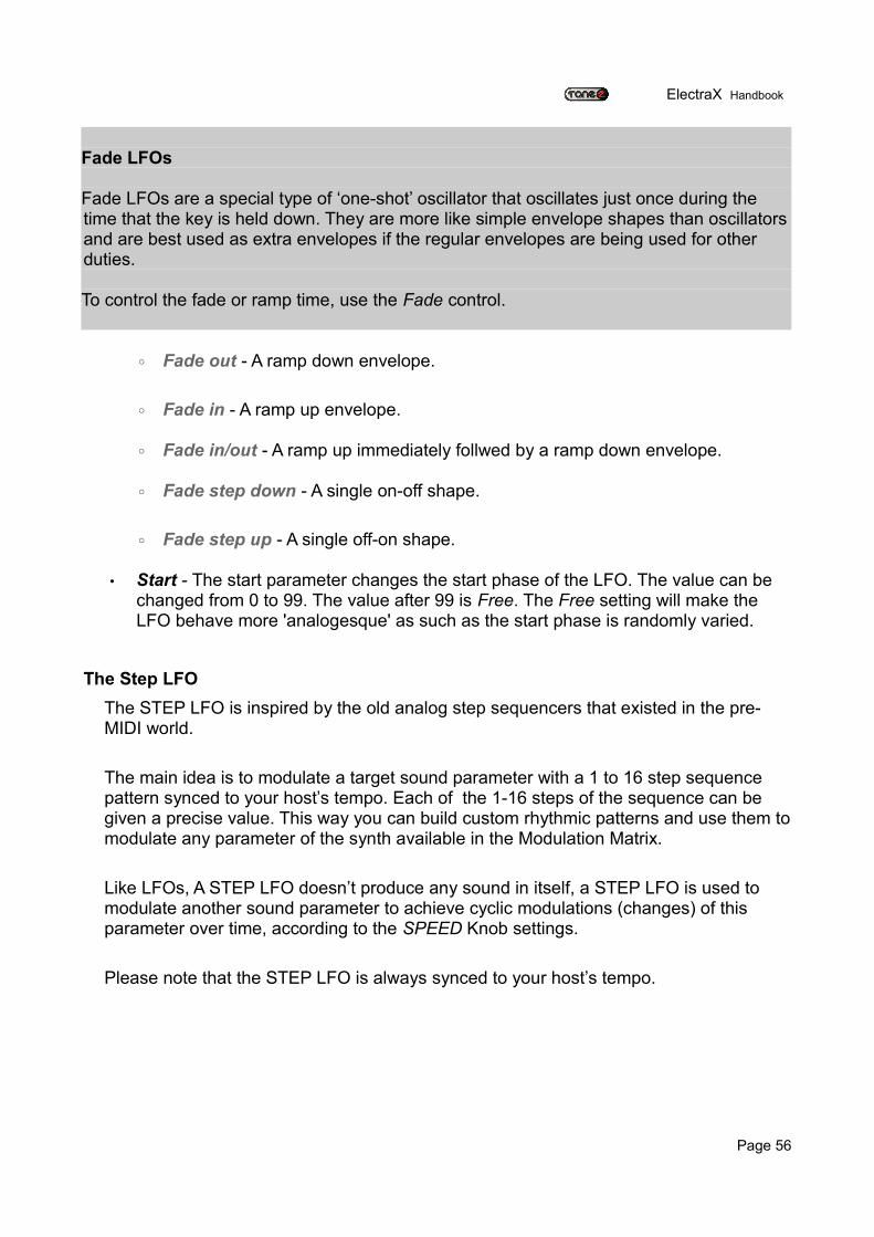
ElectraX Handbook
Fade LFOs
Fade LFOs are a special type of ‘one-shot’ oscillator that oscillates just once during the time that the key is held down. They are more like simple envelope shapes than oscillators and are best used as extra envelopes if the regular envelopes are being used for other duties.
To control the fade or ramp time, use the Fade control.
◦ Fade out - A ramp down envelope.
◦ Fade in - A ramp up envelope.
◦ Fade in/out - A ramp up immediately follwed by a ramp down envelope.
◦ Fade step down - A single on-off shape.
◦ Fade step up - A single off-on shape.
• Start - The start parameter changes the start phase of the LFO. The value can be changed from 0 to 99. The value after 99 is Free. The Free setting will make the LFO behave more 'analogesque' as such as the start phase is randomly varied.
The Step LFOThe STEP LFO is inspired by the old analog step sequencers that existed in the pre-MIDI world.
The main idea is to modulate a target sound parameter with a 1 to 16 step sequence pattern synced to your host’s tempo. Each of the 1-16 steps of the sequence can be given a precise value. This way you can build custom rhythmic patterns and use them to modulate any parameter of the synth available in the Modulation Matrix.
Like LFOs, A STEP LFO doesn’t produce any sound in itself, a STEP LFO is used to modulate another sound parameter to achieve cyclic modulations (changes) of this parameter over time, according to the SPEED Knob settings.
Please note that the STEP LFO is always synced to your host’s tempo.
Page 56
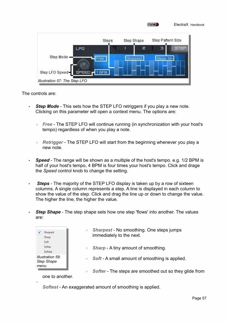
ElectraX Handbook
The controls are:
• Step Mode - This sets how the STEP LFO retriggers if you play a new note. Clicking on this parameter will open a context menu. The options are:
◦ Free - The STEP LFO will continue running (in synchronization with your host's tempo) regardless of when you play a note.
◦ Retrigger - The STEP LFO will start from the beginning whenever you play a new note.
• Speed - The range will be shown as a multiple of the host's tempo. e.g. 1/2 BPM is half of your host's tempo, 4 BPM is four times your host's tempo. Click and drage the Speed control knob to change the setting.
• Steps - The majority of the STEP LFO display is taken up by a row of sixteen columns. A single column represents a step. A line is displayed in each column to show the value of the step. Click and drag the line up or down to change the value. The higher the line, the higher the value.
• Step Shape - The step shape sets how one step 'flows' into another. The values are:
◦ Sharpest - No smoothing. One steps jumps immediately to the next.
◦ Sharp - A tiny amount of smoothing.
◦ Soft - A small amount of smoothing is applied.
◦ Softer - The steps are smoothed out so they glide from one to another.
◦Softest - An exaggerated amount of smoothing is applied.
Page 57
Illustration 57: The Step LFO
Illustration 58: Step Shape menu

ElectraX Handbook
• Step Pattern Size – Here you can set how large the pattern will be. The value can be from 2 steps to 16 steps. The pattern will repeat from the beginning once it's reached the end step.
Page 58
ElectraX Handbook
Appendix
Effects List
The effects that are used in the Master Effects and the Insert Effects sections are listed below along with their parameter descriptions..
Reverb Hall - A large Reverb simulating a Hall designed for general purpose use.Size: Adjusts the size of the simulated space.Damp: Sets the amount of time between the direct signal and the reverberated signal.Diffuse: Controls how diffused the reverb reflections are.Predelay: Sets the amount of time between the direct signal and the reverberated signal.
Reverb Cathedral – Modelling a huge space of a Cathedral with dense reflections.Size: Adjusts the size of the simulated space.Damp: Controls the amount of attenuation of the high frequencies of the reverb signal.Diffuse: Controls how diffused the reverb reflections are.Predelay: Sets the amount of time between the direct signal and the reverberated signal.
Reverb Room – Simulating a small room with a small number of reflections.Size: Adjusts the size of the simulated space.Damp: Sets the amount of time between the direct signal and the reverberated signal.Diffuse: Controls how diffused the reverb reflections are.Predelay: Sets the amount of time between the direct signal and the reverberated signal.
Page 59
ElectraX Handbook
Delay – Stereo delay which is synced to your host's tempo.Time: Sets the delay time. The delay time is set to either divisions or multiples of your host's tempo e.g. 2/3 is two thirds of your host's tempo.Feedback: Sets the amount of the delay signal that is fed back into the delay's input.Damp: Sets how much of the high frequencies are attenuated.Detune: Sets how much of the feedback signal is detuned.
Delay Band – Filtered stereo delay which is synced to your host's tempo. The frequency bandwith gets more and more narrow over time. Useful for classic psychedelic sounds from the 60's.Time: Sets the delay time. The delay time is set to either divisions or multiples of your host's tempo e.g. 2/3 is two thirds of your host's tempo.Feedback: Sets the amount of the delay signal that is fed back into the delay's input.Frequency: Sets the frequency used by the delay band's filter. Detune: Sets how much of the feedback signal is detuned.
Delay Pingpong – Tempo synced delay which alternatively pans from left to right.Time: Sets the delay time. The delay time is set to either divisions or multiples of your host's tempo e.g. 2/3 is two thirds of your host's tempo.Feedback: Sets the amount of the delay signal that is fed back into the delay's input.Damp: Sets how much of the high frequencies are attenuated.Detune: Sets how much of the feedback signal is detuned.
Multitap – Very powerful multistage delay with rhythmic beats. Also includes a number of pingpong types and a reverse delay.Time: Sets the delay time. The delay time is set to either divisions or multiples of your host's tempo e.g. 2/3 is two thirds of your host's tempo.Feedback: Sets the amount of the delay signal that is fed back into the delay's input.Mode: This sets the pattern mode of the multitap delay. The choices are:
• C_C_ : Taps play as – Center, space, Center, space. This pattern repeats for a time dependant on the Feedback setting.
• C_R_C_L : Taps play as – Center, space, Right, space, Center, space, Left. This pattern repeats for a time dependant on the Feedback setting.
• C_CC : Taps play as – Center, space, center, center. This pattern repeats for a time dependant on the Feedback setting.
• C_LR : Taps play as – Center, space, Left, Right. This pattern repeats for a time dependant on the Feedback setting.
Page 60
ElectraX Handbook
• CCC_ : Taps play as – Center, Center, Center, space. This pattern repeats for a time dependant on the Feedback setting.
• CLR_ : Taps play as – Center, Left, Right, space. This pattern repeats for a time dependant on the Feedback setting.
• C__C : Taps play as – Center, space, space, Center. This pattern repeats for a time dependant on the Feedback setting.
• L__R : Taps play as – Left, space, space, Right. This pattern repeats for a time dependant on the Feedback setting.
• Dotted 1 : The taps play as a dotted rhythm. • Dotted 2 : The taps play as a dotted rhythm as a variation of Dotted 1.• Fall : The taps make a 'falling' style of echo.• Fall LR : A falling echo on the left immediately followed by a falling echo on the
right.• Fall and Rise : A falling echo immediately followed by a reversed, rising echo.• Rise and Fall : A rising echo immediately followed by a falling echo.• Reverse : A reversed echo.• Pan 1 : A panning delay.• Pan 2 : A panning delay as a variation of Pan 1. • Pingpong 1 : A pingpong echo.• Pingpong 2 : A pingpong echo as a variation of Pingpong 1.• Chaos : Chaotic reflections.
Detune: Sets how much of the feedback signal is detuned.
Chorus – A warm stereo chorus with a rich sound.Speed: This sets the LFO speed used to modulate the frequencies of the chorus effect.Depth: How much the LFO modulates the frequency changes.
Ensemble – Simulates a large number of detuned voices playing at the same time. Adds richness and movement to sounds.Speed: This sets the LFO speed used to modulate the frequencies of the ensemble effect.
Depth: How much the LFO modulates the frequency changes.
Page 61
ElectraX Handbook
Phaser – Creates a series of peaks and troughs in the frequency spectrum. The position of the peaks and troughs is modulated so that they vary over time creating a sweeping effect.Speed: This sets the LFO speed used to modulate the frequency of the peaks and troughs.Depth: How much the LFO modulates the frequency changes.Stages: This sets how many filters are used to create the phasing effect.Center: This sets the average frequency of the phaser stages.
Flanger – Peaks and notches are produced in the resultant frequency spectrum related to each other in a linear harmonic series. Creates a sweeping effect.
Rotary – Simulates a rotary speaker/Doppler effect which was made famous by the Hammond organ.
Trancegate - Adds a rhythmic pattern to the sound. Smooth : The grade of 'softness' applied on the shape of the trancegate Speed : The speed of the trancegate synced to BPM Offset : The offset or beat of the first step of the trancegate
Compressor – Boosts the volume of lower volume notes, while capping the louder ones giving a more even level of volume.
Threshold : The level above which the signal is reduced & compression is applied Attack : The time it takes to start compressing after the threshold has been reached Release : Amount of time used to return after the input signal has fallen below threshold Ratio : Difference between the signal increase into the compressor and increase at output level
Amp sim – Simulates a guitar amplifier. Drive : Ammount of distortion Postamp : Controls the output volume
Equalizer – Parametric 3-band equalizer. Low gain : Low gain (250 Hz) High gain : High gain (3 kHz)
Page 62
ElectraX Handbook
Surround encode – Dolby Prologic II compatible surround encoder. It is also useful to add a more spatial effect to your stereo recordings. If you encode to ‘Back’ the channel will come from the rear speaker if you play your song on a surround system. The sound remains fully stereo compatible.Settings:To which speaker the signal is encoded on dolby prologic II compatible surround systems. If you select 'Center' and play back your song on a surround system the sound will come from the center speaker.
Vocoder – 10 Band Vocoder. Modulator signal/Voice/Drum loop must be routed to the left channel, carrier/synthesizer must be routed to the right channel.Formant : Formant shift of the vocoder. If you set it to 100% you'll get a child's voice. -100% will result in a very low male voice. A female voice is on 30%.Stereo : The bands of the vocoder can be spread in a wide stereo filed. Stereo controls the degree of spreading. 0% results in a mono signal.
Page 63

ElectraX Handbook
Support and Contact Information
If you have difficulties installing or using ElectraX, please contact us by visiting our website and clicking on the Support button:
Website www.tone2.com
We also have a support forum located at our website, where you can post feedback, bug reports, and ask questions:
User forum http://www.tone2.org/forum/index.php
Tone2 can also be contacted by email:
Email [email protected]
Page 64
ElectraX Handbook
Credits
Authors Daniel Sammut aka auricleBastiaan van NoordMarkus Feil
Editor Daniel Sammut
A huge THANKS! to all the beta testers, Sound Designers and Proofreaders, the usual suspects – you've all provided great ideas and feedback, we couldn't have done this without you lot!
We also want to thank everyone who pays for the software they use – our synths and FX just wouldn't happen without the support of paying customers – so a big thanks to you all!
Cheers!
The Tone2 team
Page 65


