54
DPI-2 Digital Pressure Indicator Operating Instructions DPI hand-held unit, version 2.04
DPI-2 Digital Pressure IndicatorOperating Instructions
DPI hand-held unit, version 2.04
2 Friedrich Leutert GmbH & Co. KG
Operating Instructions DPI hand-held unit, version 2.04
Introduction
This operating manual provides instructions on how to use this product correctly, effectively and safely for the intended purpose. Please, do read all instructions, notes on danger and warning, attentively. Please follow all safety instructions and precautionary notes in order to avoid damage to people or property during operation. LEUTERT can not be held responsible for damage or injury resulting from improper product use, incorrect operation or lack of maintenance.
This operating manual is directed mainly at technically trained personnel. In case of doubt regarding safety or operational aspects, please do not hesitate to contact LEUTERT for assistance. Should you notice a faulty description or depiction or if you would like to suggest points for improvement, we are looking forward to hearing from you.
Please keep the operating manual near the product to have it available if needed. Make sure that the manual is protected from dirt and moisture.
Explanation of symbols:
DANGERImmediate danger is possible causing severe injury or death if you do not follow the instructions given.
WARNINGIf you do not heed the warning, dangerous situations may occur leading to severe injury or death.
CAUTIONFollow the instructions carefully, otherwise dangerous situations may occur leading to injury or damage to property.
NOTICEPlease follow the recommendations and instructions for a correct and flawless operation of the device or measuring system.
Friedrich Leutert GmbH & Co. KG 3
Operating Instructions DPI hand-held unit, version 2.04
Contents
1 Product description ...................................................................... 4 1.1 Application and function .................................................... 4 1.2 Technical data ..................................................................... 4 1.3 Scope of delivery ................................................................. 6
2 Fundamental safety advice and recommendations ............................8
3 Design ...................................................................................... 10
4 Control and display elements .................................................... 12 4.1 General information on operating the DPI hand-held unit .... 12 4.2 The function of the buttons of the DPI hand-held unit ....... 12 4.3 Overview of the menu structure ........................................ 13
5 Start of operation ...................................................................... 14 5.1 Principal procedure for operating the DPI system ............... 14 5.2 Charge battery .................................................................. 15 5.3 Configure system .............................................................. 16 5.3.1 Set time and date ................................................... 16 5.3.2 Select language...................................................... 18 5.3.3 Enter engine parameters......................................... 19 5.4 Delete data memory ......................................................... 22 5.5 Define measuring settings ................................................. 26 5.6 Install and adjust TDC sensor ............................................. 28 5.7 Install Crank Angle Encoder CAE ....................................... 30 5.8 Installation of CAE/TDC sensor for welding of the bracket ... 32 5.9 Installing the incremental encoder ..................................... 33 5.10 Installing the Alpha Lubricator connection kit ..................... 35
6 Indication procedure ..................................................................40 6.1 Enter engine and cylinder number ..................................... 41 6.2 Record measured data ....................................................... 42 6.3 Check measuring settings and loading pressure .................44 6.4 Automatic recognition of alpha value.................................46 6.5 Complete measuring series and remove pressure sensor ..... 47 6.6 Display measuring results ...................................................48 6.6.1 View data sets at the DPI .......................................48 6.6.2 Transfer data sets to PC ..........................................48 6.7 Error messages .................................................................. 49 6.8 Warnings .......................................................................... 50
7 Maintenance ............................................................................. 51 7.1 Maintenance of the pressure sensor ................................... 51 7.2 Cleaning of the sensors ..................................................... 51 7.3 Changing the battery pack ................................................ 52
Appendix - Connecting rods ............................................................. 53
4 Friedrich Leutert GmbH & Co. KG
Operating Instructions DPI hand-held unit, version 2.04
The system components of the DPI hand-held unit and pressure sensor are adjusted to each other when they are delivered. Readjustment will be necessary if the sensor unit or the DPI hand-held unit is changed. LEUTERT will be pleased to give advice.
1 Product description
1.1 Application and function
The DPI (Digital Pressure Indicator) is a powerful and simple-to-use electronic indication device. It serves to analyze 2- and 4-stroke large diesel and gas engines in connection with the temperature compensated pressure sensor, a specially developed measuring procedure allowing a high level of precision of the measuring results.
An optional TDC sensor enables the display of the pressure curve in relation to the top dead center of the crankshaft. When a fuel injection sensor is used, the injection pressure is additionally measured. By using a crank angle encoder (CAE) or incremental encoder, each pressure value is measured as a function of the crankshaft angle.
While the measuring series is being recorded, the data may be read off the LC display of the DPI hand-held unit. At the same time, the data sets are put into memory and may be transferred to the PC via the serial interface on completion of the measuring series. The data may be depicted and administrated with the DPI software.
In order to connect the pressure sensor, the engine to be analyzed must be equipped with a standard indication valve (Thompson connection). If such a valve is not available, please contact LEUTERT.
The DPI system works independently of the mains voltage.
1.2 Technical data
Pressure range : 0 – 250 bar
Standard connection : W 27 x 1/10”
Speed range : 35 – 800 rpm for 2-stroke engines 120 – 1400 rpm for 4-stroke engines
Sampling frequency : 7.0 kHz for 2-stroke engines 16.6 kHz for 4-stroke engines
Pressure resolution : 0.07 bar for pressure range 0 – 250 bar
Accuracy : < 0.5%
Fuel injection sensor : 0 – 2000 bar, 0 – 3000 bar
Friedrich Leutert GmbH & Co. KG 5
Operating Instructions DPI hand-held unit, version 2.04
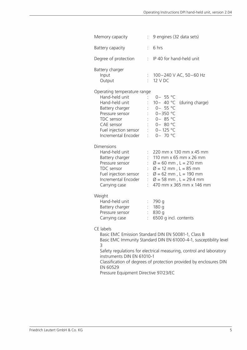
Memory capacity : 9 engines (32 data sets)
Battery capacity : 6 hrs
Degree of protection : IP 40 for hand-held unit
Battery charger Input : 100 – 240 V AC, 50 – 60 Hz Output : 12 V DC
Operating temperature range Hand-held unit : 0 – 55 °C Hand-held unit : 10 – 40 °C (during charge) Battery charger : 0 – 55 °C Pressure sensor : 0 – 350 °C TDC sensor : 0 – 85 °C CAE sensor : 0 – 80 °C Fuel injection sensor : 0 – 125 °C Incremental Encoder : 0 – 70 °C Dimensions Hand-held unit : 220 mm x 130 mm x 45 mm Battery charger : 110 mm x 65 mm x 26 mm Pressure sensor : Ø = 60 mm , L = 210 mm TDC sensor : Ø = 12 mm , L = 85 mm Fuel injection sensor : Ø = 62 mm , L = 190 mm Incremental Encoder : Ø = 58 mm , L = 29.4 mm Carrying case : 470 mm x 365 mm x 146 mm
Weight Hand-held unit : 790 g Battery charger : 180 g Pressure sensor : 830 g Carrying case : 6500 g incl. contents
CE labels Basic EMC Emission Standard DIN EN 50081-1, Class B
Basic EMC Immunity Standard DIN EN 61000-4-1, susceptibility level 3Safety regulations for electrical measuring, control and laboratory instruments DIN EN 61010-1Classification of degrees of protection provided by enclosures DIN EN 60529Pressure Equipment Directive 97/23/EC
6 Friedrich Leutert GmbH & Co. KG
Operating Instructions DPI hand-held unit, version 2.04
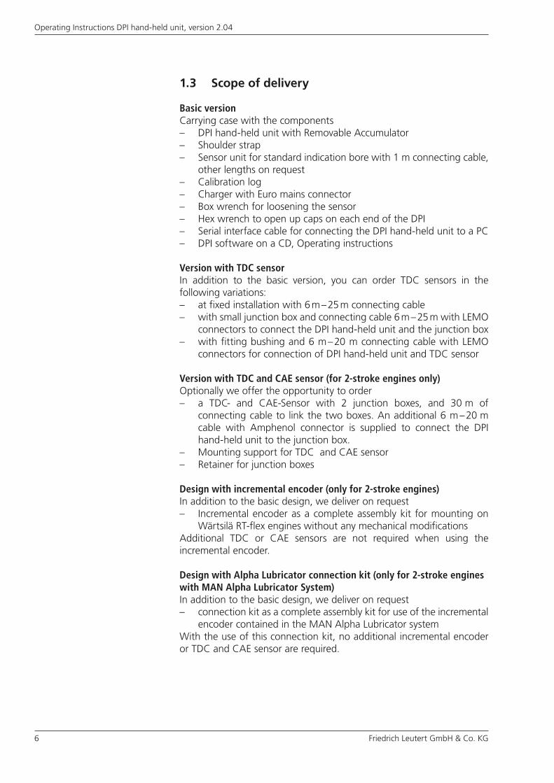
1.3 Scope of delivery
Basic versionCarrying case with the components– DPI hand-held unit with Removable Accumulator– Shoulder strap– Sensor unit for standard indication bore with 1 m connecting cable,
other lengths on request– Calibration log– Charger with Euro mains connector– Box wrench for loosening the sensor– Hex wrench to open up caps on each end of the DPI– Serial interface cable for connecting the DPI hand-held unit to a PC– DPI software on a CD, Operating instructions
Version with TDC sensorIn addition to the basic version, you can order TDC sensors in the following variations:– at fixed installation with 6 m – 25 m connecting cable– with small junction box and connecting cable 6 m – 25 m with LEMO
connectors to connect the DPI hand-held unit and the junction box– with fitting bushing and 6 m – 20 m connecting cable with LEMO
connectors for connection of DPI hand-held unit and TDC sensor
Version with TDC and CAE sensor (for 2-stroke engines only)Optionally we offer the opportunity to order– a TDC- and CAE-Sensor with 2 junction boxes, and 30 m of
connecting cable to link the two boxes. An additional 6 m – 20 m cable with Amphenol connector is supplied to connect the DPI hand-held unit to the junction box.
– Mounting support for TDC and CAE sensor– Retainer for junction boxes
Design with incremental encoder (only for 2-stroke engines)In addition to the basic design, we deliver on request– Incremental encoder as a complete assembly kit for mounting on
Wärtsilä RT-flex engines without any mechanical modificationsAdditional TDC or CAE sensors are not required when using the incremental encoder.
Design with Alpha Lubricator connection kit (only for 2-stroke engines with MAN Alpha Lubricator System)In addition to the basic design, we deliver on request– connection kit as a complete assembly kit for use of the incremental
encoder contained in the MAN Alpha Lubricator systemWith the use of this connection kit, no additional incremental encoder or TDC and CAE sensor are required.

Friedrich Leutert GmbH & Co. KG 7
Operating Instructions DPI hand-held unit, version 2.04
Version with Fuel injection sensorAs a supplement to the variants with TDC or TDC/CAE sensor or incremental encoder, you can order:– Fuel injection sensor– Safety valves corresponding to the amount of cylinders.
Accessories for all versions– Magnets, Adhesive, Distance gauge– Adapter cable USB - serial with driver software
8 Friedrich Leutert GmbH & Co. KG
Operating Instructions DPI hand-held unit, version 2.04
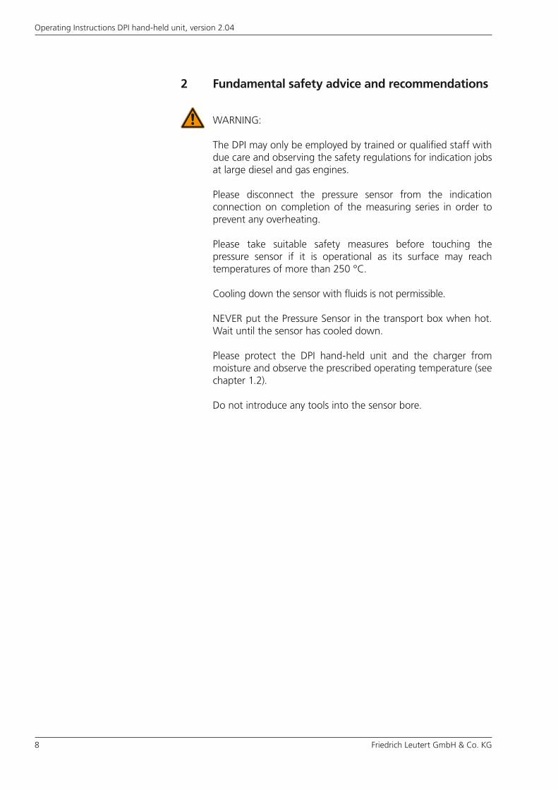
2 Fundamental safety advice and recommendations
WARNING:
The DPI may only be employed by trained or qualified staff with due care and observing the safety regulations for indication jobs at large diesel and gas engines.
Please disconnect the pressure sensor from the indication connection on completion of the measuring series in order to prevent any overheating.
Please take suitable safety measures before touching the pressure sensor if it is operational as its surface may reach temperatures of more than 250 °C.
Cooling down the sensor with fluids is not permissible.
NEVER put the Pressure Sensor in the transport box when hot. Wait until the sensor has cooled down.
Please protect the DPI hand-held unit and the charger from moisture and observe the prescribed operating temperature (see chapter 1.2).
Do not introduce any tools into the sensor bore.
Friedrich Leutert GmbH & Co. KG 9
Operating Instructions DPI hand-held unit, version 2.04
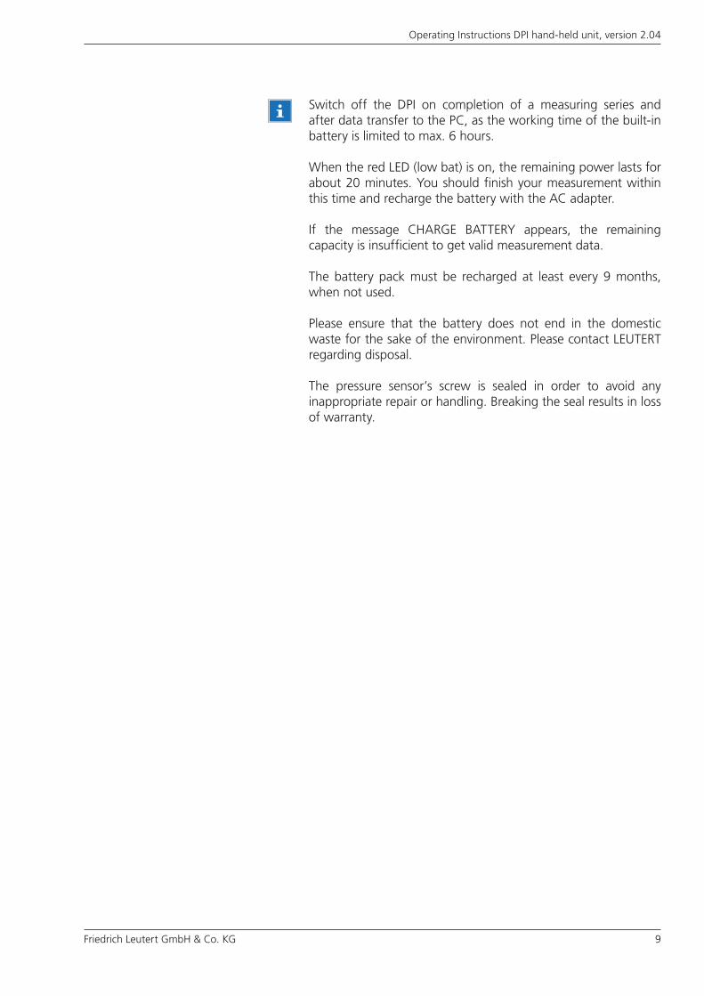
Switch off the DPI on completion of a measuring series and after data transfer to the PC, as the working time of the built-in battery is limited to max. 6 hours.
When the red LED (low bat) is on, the remaining power lasts for about 20 minutes. You should finish your measurement within this time and recharge the battery with the AC adapter.
If the message CHARGE BATTERY appears, the remaining capacity is insufficient to get valid measurement data.
The battery pack must be recharged at least every 9 months, when not used.
Please ensure that the battery does not end in the domestic waste for the sake of the environment. Please contact LEUTERT regarding disposal.
The pressure sensor’s screw is sealed in order to avoid any inappropriate repair or handling. Breaking the seal results in loss of warranty.
10 Friedrich Leutert GmbH & Co. KG
Operating Instructions DPI hand-held unit, version 2.04
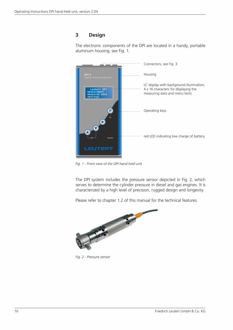
3 Design
The electronic components of the DPI are located in a handy, portable aluminum housing, see Fig. 1.
The DPI system includes the pressure sensor depicted in Fig. 2, which serves to determine the cylinder pressure in diesel and gas engines. It is characterized by a high level of precision, rugged design and longevity.
Please refer to chapter 1.2 of this manual for the technical features.
Fig. 2 - Pressure sensor
Fig. 1 - Front view of the DPI hand-held unit
Operating keys
Housing
LC display with background illumination, 4 x 16 characters for displaying the measuring data and menu texts
Connectors, see Fig. 3
red LED indicating low charge of battery
Friedrich Leutert GmbH & Co. KG 11
Operating Instructions DPI hand-held unit, version 2.04
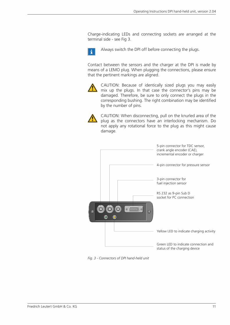
Charge-indicating LEDs and connecting sockets are arranged at the terminal side - see Fig 3.
Contact between the sensors and the charger at the DPI is made by means of a LEMO plug. When plugging the connections, please ensure that the pertinent markings are aligned.
Fig. 3 - Connectors of DPI hand-held unit
Always switch the DPI off before connecting the plugs.
CAUTION: When disconnecting, pull on the knurled area of the plug as the connectors have an interlocking mechanism. Do not apply any rotational force to the plug as this might cause damage.
4-pin connector for pressure sensor
3-pin connector for fuel injection sensor
RS 232 as 9-pin Sub D socket for PC connection
Green LED to indicate connection and status of the charging device
5-pin connector for TDC sensor, crank angle encoder (CAE), incremental encoder or charger
Yellow LED to indicate charging activity
CAUTION: Because of identically sized plugs you may easily mix up the plugs. In that case the connector’s pins may be damaged. Therefore, be sure to only connect the plugs in the corresponding bushing. The right combination may be identified by the number of pins.
12 Friedrich Leutert GmbH & Co. KG
Operating Instructions DPI hand-held unit, version 2.04
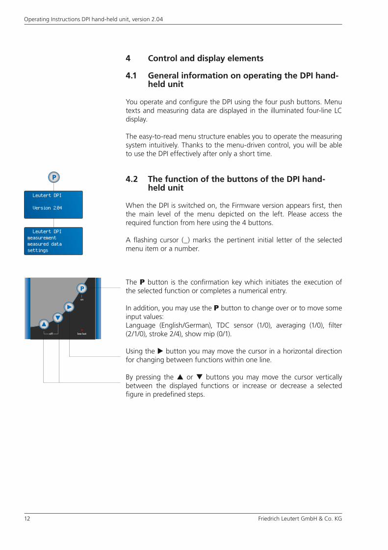
4.2 The function of the buttons of the DPI hand- held unit
When the DPI is switched on, the Firmware version appears first, then the main level of the menu depicted on the left. Please access the required function from here using the 4 buttons.
A flashing cursor (_) marks the pertinent initial letter of the selected menu item or a number.
The P button is the confirmation key which initiates the execution of the selected function or completes a numerical entry.
In addition, you may use the P button to change over or to move some input values:Language (English/German), TDC sensor (1/0), averaging (1/0), filter (2/1/0), stroke 2/4), show mip (0/1).
Using the button you may move the cursor in a horizontal direction for changing between functions within one line.
By pressing the or buttons you may move the cursor vertically between the displayed functions or increase or decrease a selected figure in predefined steps.
4 Control and display elements
4.1 General information on operating the DPI hand- held unit
You operate and configure the DPI using the four push buttons. Menu texts and measuring data are displayed in the illuminated four-line LC display.
The easy-to-read menu structure enables you to operate the measuring system intuitively. Thanks to the menu-driven control, you will be able to use the DPI effectively after only a short time.
Leutert DPImeasurementmeasured datasettings
Leutert DPI
Version 2.04
Friedrich Leutert GmbH & Co. KG 13
Operating Instructions DPI hand-held unit, version 2.04
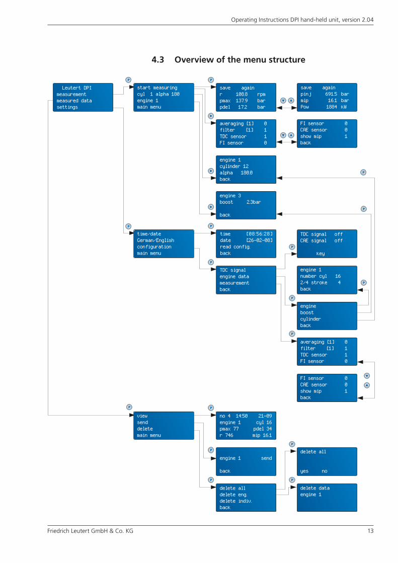
4.3 Overview of the menu structure
save againpinj 691.5 barmip 16.1 barPow 1884 kW
save againr 108.8 rpmpmax 137.9 barpdel 17.2 bar
start measuringcyl 1 alpha 180engine 1main menu
engine 1cylinder 12alpha 180.0back
engine 3boost 2.3bar
back
time/dateGerman/Englishconfigurationmain menu
time [08:56:28]date [26-02-08]read config.back
engine 1number cyl 162/4 stroke 4back
TDC signalengine datameasurementback
engineboostcylinderback
viewsenddeletemain menu
no 4 14:50 21-09engine 1 cyl 16pmax 77 pdel 34r 746 mip 16.1
engine 1 send
back
delete alldelete eng.delete indiv.back
delete dataengine 1
averaging [1] 0 filter [1] 1TDC sensor 1FI sensor 0
FI sensor 0CAE sensor 0show mip 1back
averaging [1] 0 filter [1] 1TDC sensor 1FI sensor 0
delete all
yes no
FI sensor 0CAE sensor 0show mip 1back
TDC signal offCAE signal off
key
Leutert DPImeasurementmeasured datasettings
14 Friedrich Leutert GmbH & Co. KG
Operating Instructions DPI hand-held unit, version 2.04
5 Start of operation
5.1 Principal procedure for operating the DPI system
1) Charge battery You should charge the battery built into the DPI as a matter of course
when the charge message appears respect. after 6 months of disuse.
2) Configure system You should prepare the measuring system for the specific operating
conditions, so that it will provide the correct results. This includes entry of the engine parameters and setting date and time. Enter these settings on the DPI hand-held unit where they will be put into memory and will still be available when the unit is switched off and back on again.
3) Delete data memory We recommend that you delete the data sets put into memory in
the DPI completely before starting a new measuring series. The configuration settings are not affected by this!
4) Preset measuring settings Use the filter or average generation function to prevent unwanted
interference of the measuring results.
5) Installing optional sensors Install and, if required, adjust the TDC sensor, crank angle encoder
(CAE), incremental encoder, or Alpha Lubricator connection kit. Mount the sensors on the engine in accordance with the instructions.
6) Install pressure sensor Install the pressure sensor at the indication bore of the diesel and
gas engine. At the beginning of the measurement, when the sensor still is cool, do not tighten the sensor hard to the cylinder in order to prevent it from getting stuck.
7) Install fuel injection sensor Install the fuel injection sensor on the appropriate mounting hole
of the respective injection pump.
8) Connect sensors at the DPI hand-held unit and record measuring data
Connect the sensors with the DPI hand-held unit and carry out the measuring series. The DPI stores the measuring data of a maximum of 32 cylinders. You have the option of following the measuring procedure on the display of the DPI and, as necessary, of reacting to error messages with corresponding measures.
9) Display measuring data You may view stored data sets independently of the measuring
location on the display or transfer them to a PC, in order to carry out a machine diagnosis with the assistance of the DPI software.
Friedrich Leutert GmbH & Co. KG 15
Operating Instructions DPI hand-held unit, version 2.04
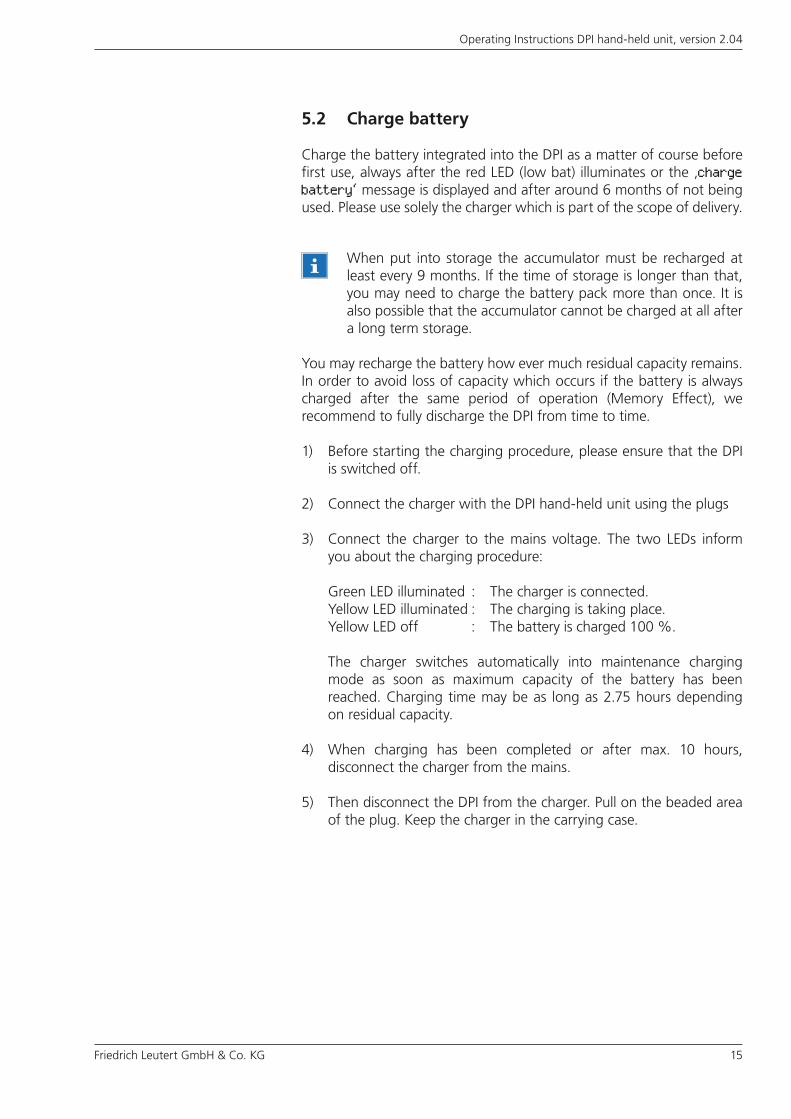
5.2 Charge battery
Charge the battery integrated into the DPI as a matter of course before first use, always after the red LED (low bat) illuminates or the ‚charge battery‘ message is displayed and after around 6 months of not being used. Please use solely the charger which is part of the scope of delivery.
You may recharge the battery how ever much residual capacity remains. In order to avoid loss of capacity which occurs if the battery is always charged after the same period of operation (Memory Effect), we recommend to fully discharge the DPI from time to time.
1) Before starting the charging procedure, please ensure that the DPI is switched off.
2) Connect the charger with the DPI hand-held unit using the plugs
3) Connect the charger to the mains voltage. The two LEDs inform you about the charging procedure:
Green LED illuminated : The charger is connected. Yellow LED illuminated : The charging is taking place. Yellow LED off : The battery is charged 100 %.
The charger switches automatically into maintenance charging mode as soon as maximum capacity of the battery has been reached. Charging time may be as long as 2.75 hours depending on residual capacity.
4) When charging has been completed or after max. 10 hours, disconnect the charger from the mains.
5) Then disconnect the DPI from the charger. Pull on the beaded area of the plug. Keep the charger in the carrying case.
When put into storage the accumulator must be recharged at least every 9 months. If the time of storage is longer than that, you may need to charge the battery pack more than once. It is also possible that the accumulator cannot be charged at all after a long term storage.

16 Friedrich Leutert GmbH & Co. KG
Operating Instructions DPI hand-held unit, version 2.04
5.3 Configure system
Please configure the measuring system when using it for the first time and when parameters have been changed. The configured values are maintained even when the DPI hand-held unit is switched off.
5) When the cursor is in the line to be processed, press P to activate the programing. The cursor switches to the first changeable number.
5.3.1 Set time and date
The correct value for time and date is necessary to ensure exact temporal allocation of the results gained during indicating.
Time and date are pre-set to CET (Central European Time). Due to the inaccuracy of 1 min. per day, you should eliminate any differences occurring. Also make this correction for changing between summer and winter time.
The time is displayed in hours:minutes:seconds, the date is displayed in the format Day - Month - Year.
1) Switch on the DPI hand-held unit by pressing the P button. The DPI start menu appears on the display.
3) Confirm the opening of the Settings menu using P. In the following display the cursor will be seen in the ‚time/date‘ line.
2) Press or button, until the flashing cursor is in the ‚settings‘ line.
4) Pressing the P button again will take you to the setting window for time and date. The flashing cursor is the ‚time‘ line.
Leutert DPImeasurementmeasured datasettings
Leutert DPImeasurementmeasured datasettings
time/dateGerman/Englishconfigurationmain menu
time [08:56:28]date [26-02-08]read config. back
Friedrich Leutert GmbH & Co. KG 17
Operating Instructions DPI hand-held unit, version 2.04
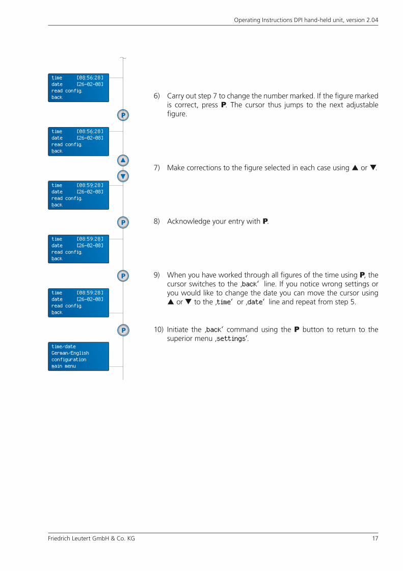
6) Carry out step 7 to change the number marked. If the figure marked is correct, press P. The cursor thus jumps to the next adjustable figure.
7) Make corrections to the figure selected in each case using or .
8) Acknowledge your entry with P.
10) Initiate the ‚back‘ command using the P button to return to the superior menu ‚settings‘.
9) When you have worked through all figures of the time using P, the cursor switches to the ‚back‘ line. If you notice wrong settings or you would like to change the date you can move the cursor using or to the ‚time‘ or ‚date‘ line and repeat from step 5.
time [08:56:28]date [26-02-08]read config. back
time [08:56:28]date [26-02-08]read config. back
time [08:59:28]date [26-02-08]read config. back
time [08:59:28]date [26-02-08]read config. back
time [08:59:28]date [26-02-08]read config. back
time/dateGerman/Englishconfigurationmain menu

18 Friedrich Leutert GmbH & Co. KG
Operating Instructions DPI hand-held unit, version 2.04
5.3.2 Select language
Here you select whether the menu texts are to be displayed in English or German language. Other languages are available as options.
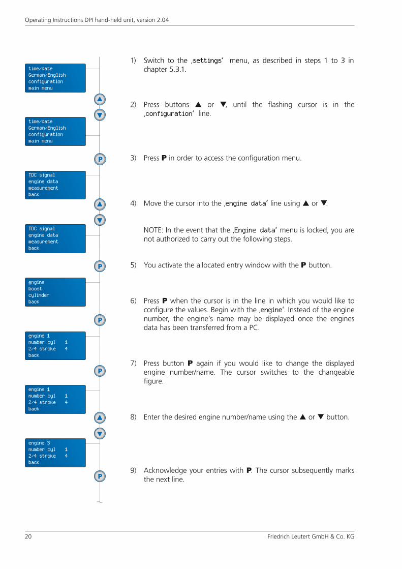
1) Move to the ‚settings‘ menu, as described in steps 1 to 3 in chapter 5.3.1.
2) Press button or , until the flashing cursor is in the line ‚German/English‘.
3) Use the P button to switch between the two languages. The menu texts always appear in the language currently activated. The cursor marks the language currently not selected.
4) If you have the menu texts in the preferred language, move the cursor using the or buttons for setting further items or switch back to the main level.
time/dateGerman/Englishconfigurationmain manu
time/dateGerman/Englishconfigurationmain menu
Uhrzeit/DatumEnglisch/DeutschKonfigurationHauptebene
time/dateGerman/Englishconfigurationmain menu
time/dateGerman/Englishconfigurationmain menu
Friedrich Leutert GmbH & Co. KG 19
Operating Instructions DPI hand-held unit, version 2.04
Always use the correct engine number or name respectively during indication so that the DPI can work with the pertinent parameters.
5.3.3 Enter engine parameters
Enter the engine parameters once for every engine when it is put into operation for the first time, or change engine characteristic values as necessary. Make sure the entries are correct so that the DPI will supply you with accurate measuring results.
Define the following engine data in the given ranges:
Engine number 1 – 9Number of cylinders 1 – 24Alpha (TDC offset) 0 – 360.0 in 0.5 °CA stepsBoost pressure 0 – 5.0 bar in 0.1 bar steps
Allocation of an engine number serves to differentiate between various engines on board, as necessary, and enables clear allocation of the measuring data to the engine. The alpha value indicates the TDC offset of the respective cylinder in relation to the TDC of cylinder no. 1. The following example shall illustrate this to you:
Engine with 9 cylinders in line, ignition interval 40 °CA
Input of individual parameters into the DPI hand-held unitThe following work steps adapt the measuring system to the diesel and gas engines to be analyzed. You may enter and store the parameters of a maximum of 9 engines in the DPI. These settings remain until replaced by a new configuration.
How to load all parameters from a computerThe definition of the engine parameter may be done on the PC. Then they have to be transmitted to the DPI hand-held unit. Refer to chapter 4 in the DPI software manual.
(Cylinder no.)Firing order 1 9 2 7 4 5 6 3 8Alpha 0 40 80 120 160 200 240 280 320 (TDC offset)
Starting from version 3.24, the DPI software contains a password-protected option for locking the engine parameters and measurement settings. If these have already been entered in the software and transmitted to the DPI hand held unit, it is not possible to enter or change engine parameters on the DPI hand-held unit with the lock enabled. If required, contact the person responsible for password administration.
20 Friedrich Leutert GmbH & Co. KG
Operating Instructions DPI hand-held unit, version 2.04
9) Acknowledge your entries with P. The cursor subsequently marks the next line.
1) Switch to the ‚settings‘ menu, as described in steps 1 to 3 in chapter 5.3.1.
2) Press buttons or , until the flashing cursor is in the ‚configuration‘ line.
3) Press P in order to access the configuration menu.
4) Move the cursor into the ‚engine data‘ line using or .
5) You activate the allocated entry window with the P button.
7) Press button P again if you would like to change the displayed engine number/name. The cursor switches to the changeable figure.
6) Press P when the cursor is in the line in which you would like to configure the values. Begin with the ‚engine‘. Instead of the engine number, the engine’s name may be displayed once the engines data has been transferred from a PC.
8) Enter the desired engine number/name using the or button.
NOTE: In the event that the ‚Engine data‘ menu is locked, you are not authorized to carry out the following steps.
time/dateGerman/Englishconfigurationmain menu
time/dateGerman/Englishconfigurationmain menu
TDC signalengine datameasurementback
TDC signalengine datameasurementback
engineboostcylinderback
engine 1number cyl 12/4 stroke 4back
engine 1number cyl 12/4 stroke 4back
engine 3number cyl 12/4 stroke 4back
Friedrich Leutert GmbH & Co. KG 21
Operating Instructions DPI hand-held unit, version 2.04
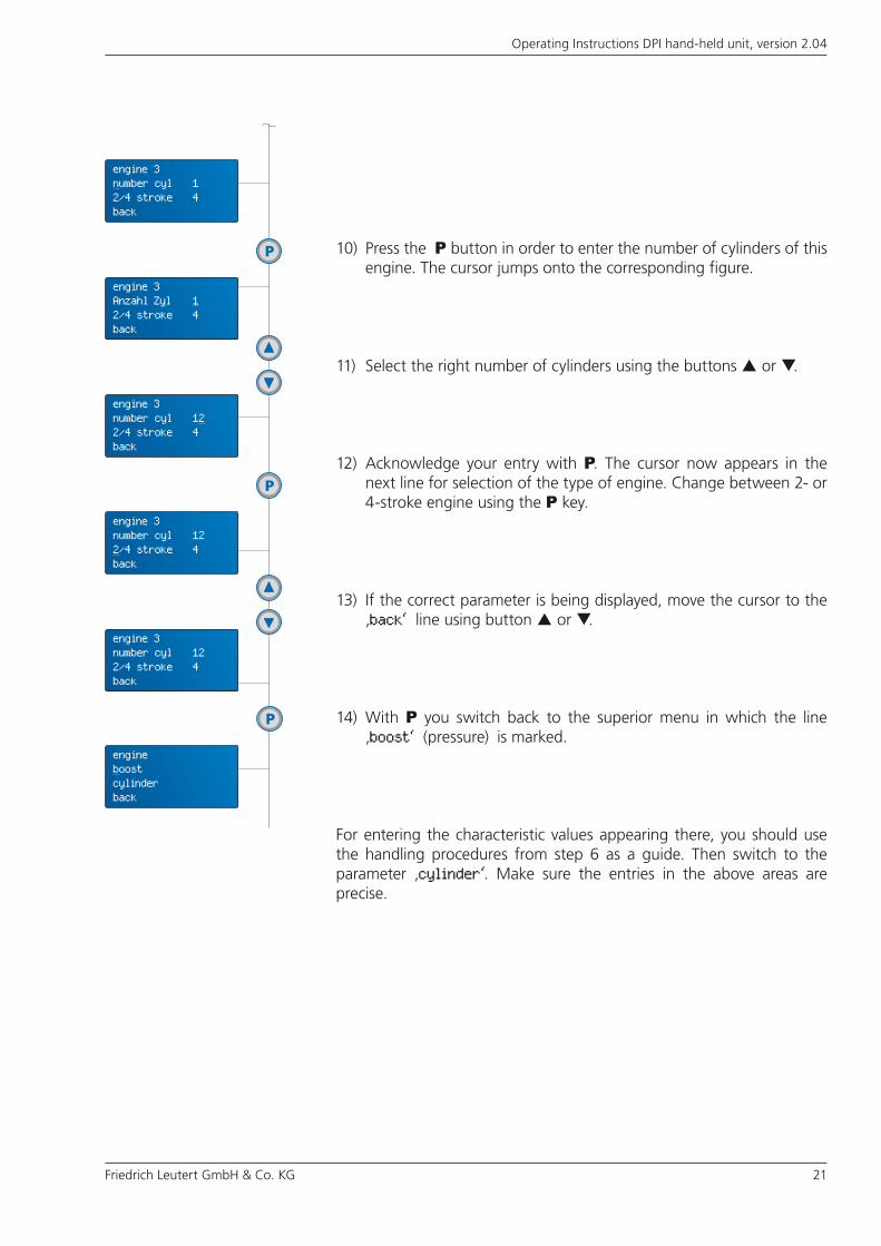
10) Press the P button in order to enter the number of cylinders of this engine. The cursor jumps onto the corresponding figure.
14) With P you switch back to the superior menu in which the line ‚boost‘ (pressure) is marked.
For entering the characteristic values appearing there, you should use the handling procedures from step 6 as a guide. Then switch to the parameter ‚cylinder‘. Make sure the entries in the above areas are precise.
12) Acknowledge your entry with P. The cursor now appears in the next line for selection of the type of engine. Change between 2- or 4-stroke engine using the P key.
11) Select the right number of cylinders using the buttons or .
13) If the correct parameter is being displayed, move the cursor to the ‚back‘ line using button or .
engine 3number cyl 12/4 stroke 4back
engine 3Anzahl Zyl 12/4 stroke 4back
engine 3number cyl 122/4 stroke 4back
engine 3number cyl 122/4 stroke 4back
engine 3number cyl 122/4 stroke 4back
engineboostcylinderback
22 Friedrich Leutert GmbH & Co. KG
Operating Instructions DPI hand-held unit, version 2.04
5.4 Delete data memory
The DPI stores the measured values from a measuring series in the form of data sets on the cylinder selected in each case.
If you want to record measured values beyond the 32 data sets, you must replace data already stored, see chapter 6.2.
In order to avoid this, we recommend either completely deleting the data memory or individually deleting the engine data before starting a new measuring series.
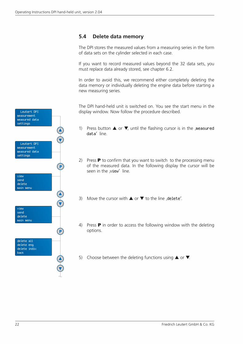
The DPI hand-held unit is switched on. You see the start menu in the display window. Now follow the procedure described.
2) Press P to confirm that you want to switch to the processing menu of the measured data. In the following display the cursor will be seen in the ‚view‘ line.
1) Press button or , until the flashing cursor is in the ‚measured data‘ line.
3) Move the cursor with or to the line ‚delete‘.
4) Press P in order to access the following window with the deleting options.
5) Choose between the deleting functions using or .
Leutert DPImeasurementmeasured datasettings
Leutert DPImeasurementmeasured datasettings
viewsenddeletemain menu
viewsenddeletemain menu
delete alldelete eng.delete indiv.back
Friedrich Leutert GmbH & Co. KG 23
Operating Instructions DPI hand-held unit, version 2.04
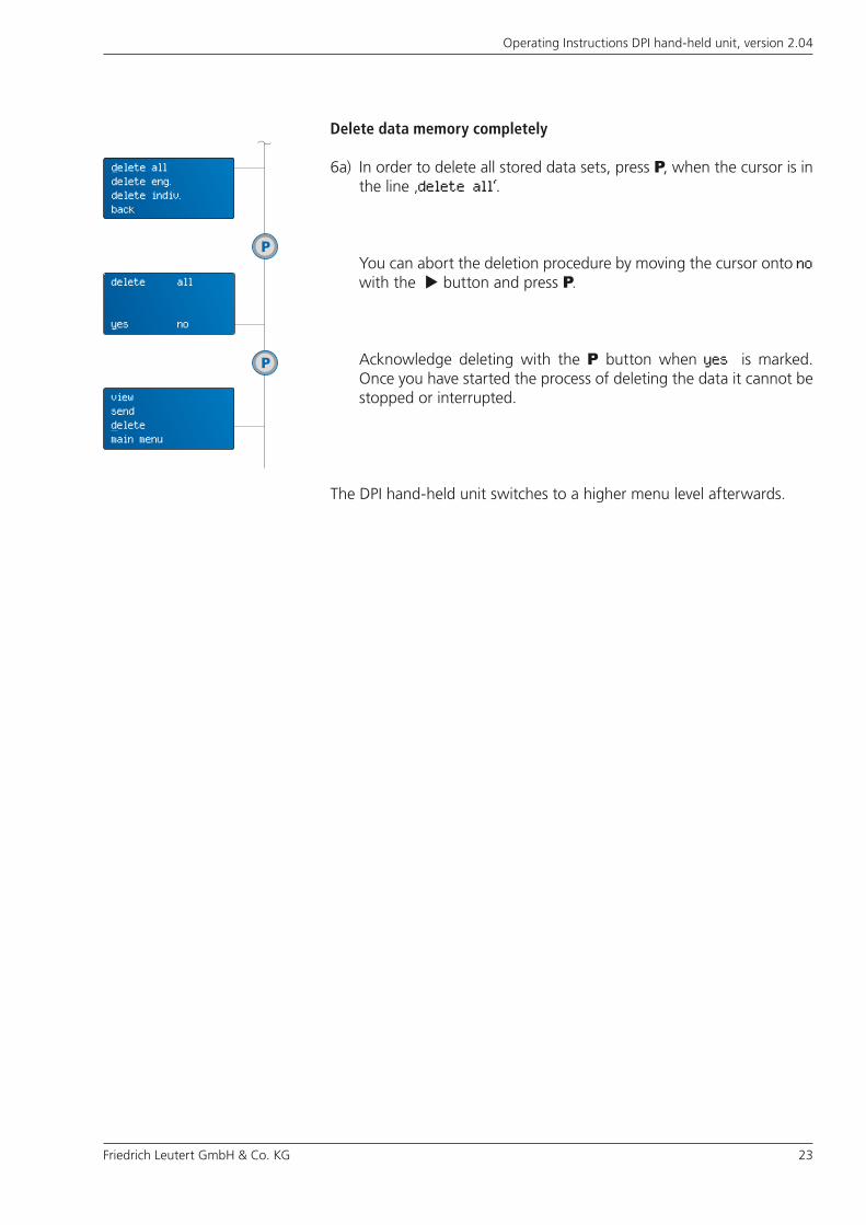
6a) In order to delete all stored data sets, press P, when the cursor is in the line ‚delete all‘.
You can abort the deletion procedure by moving the cursor onto no with the button and press P.
Acknowledge deleting with the P button when yes is marked. Once you have started the process of deleting the data it cannot be stopped or interrupted.
The DPI hand-held unit switches to a higher menu level afterwards.
Delete data memory completely
delete alldelete eng.delete indiv.back
delete all
yes no
viewsenddeletemain menu

24 Friedrich Leutert GmbH & Co. KG
Operating Instructions DPI hand-held unit, version 2.04
7b) With the command ‚back‘ you get back to the pertinent superior menu level. Navigate to the required setting level using the buttons.
6b) If you want to delete only data sets of one engine, move the cursor to ‚delete eng.‘ and press P.
Pick the engine to be deleted by using the keys.
To delete data of other engines just follow the procedure described above.
At this stage you can abort the process by moving the cursor with the key to no and confirm with P.
Otherwise just confirm the deletion of the engine by pressing P. Once you have started the process of deleting the data it cannot be stopped or interrupted.
When the designated engine’s identification is shown on the display, press P.
Deleting data sets of an engine
delete alldelete eng.delete indiv.back
delete dataengine 1
delete alldelete eng.delete indiv.back
delete dataengine 5
delete dataengine 5
yes no
Friedrich Leutert GmbH & Co. KG 25
Operating Instructions DPI hand-held unit, version 2.04
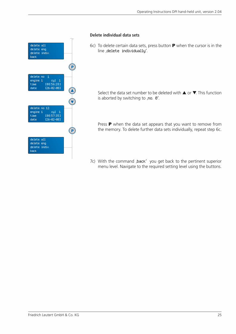
6c) To delete certain data sets, press button P when the cursor is in the line ‚delete individually‘.
Select the data set number to be deleted with or . This function is aborted by switching to ‚no. 0‘.
Press P when the data set appears that you want to remove from the memory. To delete further data sets individually, repeat step 6c.
Delete individual data sets
7c) With the command ‚back‘ you get back to the pertinent superior menu level. Navigate to the required setting level using the buttons.
delete alldelete eng.delete indiv.back
delete no 1 engine 1 cyl 1 time [08:56:28]date [26-02-08]
delete alldelete eng.delete indiv.back
delete no 13engine 1 cyl 1 time [08:57:35]date [26-02-08]
26 Friedrich Leutert GmbH & Co. KG
Operating Instructions DPI hand-held unit, version 2.04
Make use of the DPI’s ability to prevent interference affecting the measuring results by selecting certain measuring settings. In this way you get results that enable you to compare the measuring data of the individual cylinders. For indication the DPI uses the pertinent currently set measuring settings for all engines. These are stored until redefined.
Provided that you are authorized to do so, you may also define the measurement settings in the DPI software on the PC and transmit them to the DPI hand-held unit, see chapter 4 of the DPI software manual.
Access the menu depicted at the very bottom at the DPI to carry out the following settings. In the meantime you are surely familiar enough with the button operation that it is not necessary to mention every individual single actuation of a button.
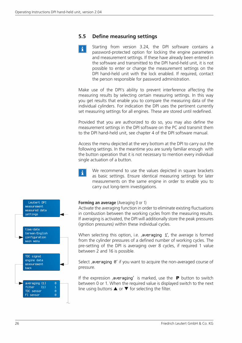
Forming an average (Averaging 0 or 1)Activate the averaging function in order to eliminate existing fluctuations in combustion between the working cycles from the measuring results. If averaging is activated, the DPI will additionally store the peak pressures (ignition pressures) within these individual cycles.
When selecting this option, i.e. ‚averaging 1‘, the average is formed from the cylinder pressures of a defined number of working cycles. The pre-setting of the DPI is averaging over 8 cycles, if required 1 value between 2 and 16 is possible.
Select ‚averaging 0‘ if you want to acquire the non-averaged course of pressure.
If the expression ‚averaging‘ is marked, use the P button to switch between 0 or 1. When the required value is displayed switch to the next line using buttons or for selecting the filter.
We recommend to use the values depicted in square brackets as basic settings. Ensure identical measuring settings for later measurements on the same engine in order to enable you to carry out long-term investigations.
5.5 Define measuring settings
Starting from version 3.24, the DPI software contains a password-protected option for locking the engine parameters and measurement settings. If these have already been entered in the software and transmitted to the DPI hand-held unit, it is not possible to enter or change the measurement settings on the DPI hand-held unit with the lock enabled. If required, contact the person responsible for password administration.
Leutert DPImeasurementmeasured datasettings
time/dateGerman/Englishconfigurationmain menu
TDC signalengine datameasurementback
averaging [1] 0filter [1] 1TDC sensor 0FI sensor 0
Friedrich Leutert GmbH & Co. KG 27
Operating Instructions DPI hand-held unit, version 2.04
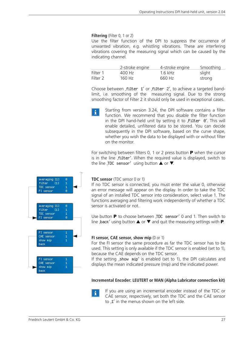
FI sensor, CAE sensor, show mip (0 or 1)For the FI sensor the same procedure as far the TDC sensor has to be used. This setting is only available if the TDC sensor is enabled (set to 1), because the CAE depends on the TDC sensor.If the setting ‚show mip‘ is enabled (set to 1), the DPI calculates and displays the mean indicated pressure (mip) and the indicated power.
Filtering (Filter 0, 1 or 2)Use the filter function of the DPI to suppress the occurrence of unwanted vibration, e.g. whistling vibrations. These are interfering vibrations covering the measuring signal which can be caused by the indicating channel.
2-stroke engine 4-stroke engine SmoothingFilter 1 400 Hz 1.6 kHz slightFilter 2 160 Hz 660 Hz strong
Choose between ‚filter 1‘ or ‚filter 2‘, to achieve a targeted band-limit, i.e. smoothing of the measuring signal. Due to the strong smoothing factor of Filter 2 it should only be used in exceptional cases.
Starting from version 3.24, the DPI software contains a filter function. We recommend that you disable the filter function in the DPI hand-held unit by setting it to ‚Filter 0‘. This will enable detailed, unfiltered data to be stored. You can decide subsequently in the DPI software, based on the curve shape, whether you wish the data to be displayed with or without filter on the monitor.
For switching between filters 0, 1 or 2 press button P when the cursor is in the line ‚filter‘. When the required value is displayed, switch to the line ‚TDC sensor‘ using button or .
TDC sensor (TDC sensor 0 or 1)If no TDC sensor is connected, you must enter the value 0, otherwise an error message will appear on the display. In order to take the TDC signal of an installed TDC sensor into consideration, select value 1. The functions averaging and filtering work independently of whether a TDC sensor is activated or not.
Use button P to choose between ‚TDC sensor‘ 0 and 1. Then switch to line ‚back‘ using button or and quit the measuring settings with P.
Incremental Encoder: LEUTERT or MAN (Alpha Lubricator connection kit)
If you are using an incremental encoder instead of the TDC or CAE sensor, respectively, set both the TDC and the CAE sensor to ‚1‘ in the menus shown on the left side.
averaging [1] 0 filter [1] 1TDC sensor 1FI sensor 0
averaging [1] 0 filter [1] 1TDC sensor 1FI sensor 0
FI sensor 1CAE sensor 1show mip 1back
FI sensor 1CAE sensor 1show mip 1back
28 Friedrich Leutert GmbH & Co. KG
Operating Instructions DPI hand-held unit, version 2.04
5.6 Install and adjust TDC sensor
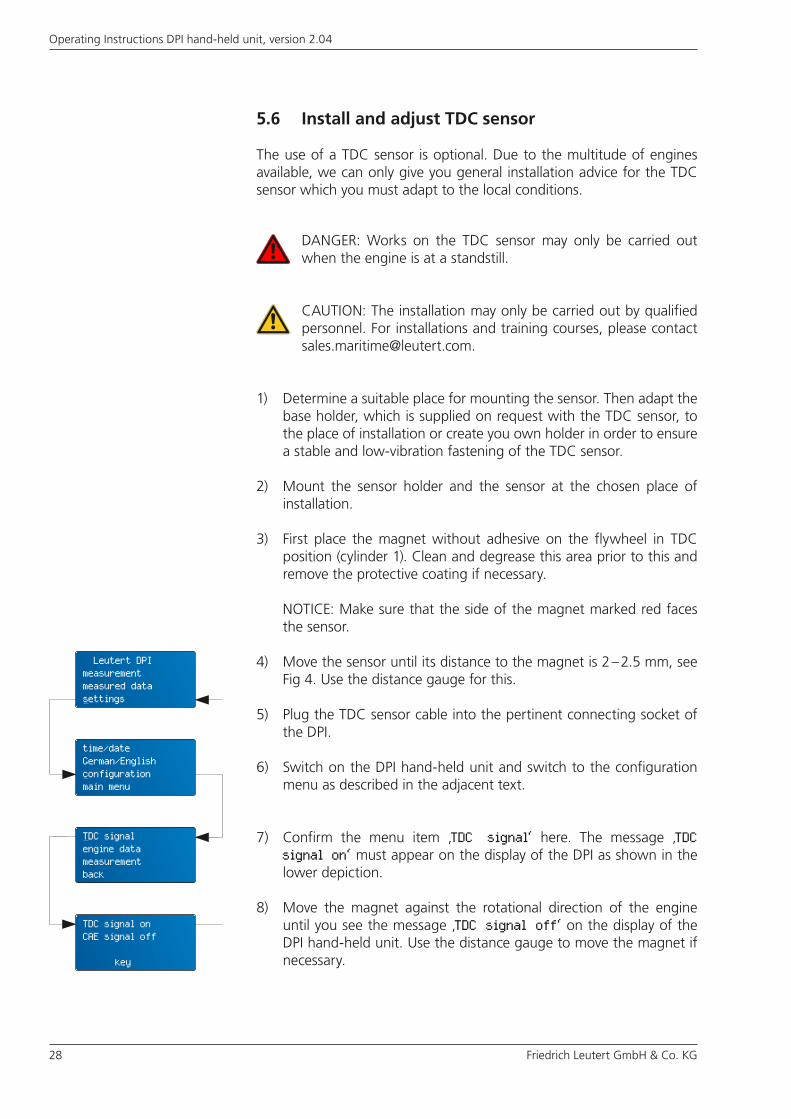
The use of a TDC sensor is optional. Due to the multitude of engines available, we can only give you general installation advice for the TDC sensor which you must adapt to the local conditions.
1) Determine a suitable place for mounting the sensor. Then adapt the base holder, which is supplied on request with the TDC sensor, to the place of installation or create you own holder in order to ensure a stable and low-vibration fastening of the TDC sensor.
2) Mount the sensor holder and the sensor at the chosen place of installation.
3) First place the magnet without adhesive on the flywheel in TDC position (cylinder 1). Clean and degrease this area prior to this and remove the protective coating if necessary.
4) Move the sensor until its distance to the magnet is 2 – 2.5 mm, see Fig 4. Use the distance gauge for this.
5) Plug the TDC sensor cable into the pertinent connecting socket of the DPI.
6) Switch on the DPI hand-held unit and switch to the configuration menu as described in the adjacent text.
7) Confirm the menu item ‚TDC signal‘ here. The message ‚TDC signal on‘ must appear on the display of the DPI as shown in the lower depiction.
8) Move the magnet against the rotational direction of the engine until you see the message ‚TDC signal off‘ on the display of the DPI hand-held unit. Use the distance gauge to move the magnet if necessary.
NOTICE: Make sure that the side of the magnet marked red faces the sensor.
DANGER: Works on the TDC sensor may only be carried out when the engine is at a standstill.
CAUTION: The installation may only be carried out by qualified personnel. For installations and training courses, please contact [email protected].
Leutert DPImeasurementmeasured datasettings
time/dateGerman/Englishconfigurationmain menu
TDC signalengine datameasurementback
TDC signal onCAE signal off
key

Friedrich Leutert GmbH & Co. KG 29
Operating Instructions DPI hand-held unit, version 2.04
Fig. 4 - Surface mounting of the TDC sensor at different flywheel positions
9) Now move the magnet carefully back as far as necessary until ‚TDC signal on‘ appears again on the display. Mark this position.
10) In the case of a surface mounting like in Fig. 4, fix the magnet with adhesive exactly on the marked position. Please also read the advice for using the adhesive supplied.
11) To implement a flush mounting as in Fig. 5, do the drilling in such a way that the magnet projects at least 2.5 mm after being inserted. Then readjust the distance of the magnet to the sensor.
Fig. 5 - Flush mounting of the magnet
magnet
TDC sensor
30 Friedrich Leutert GmbH & Co. KG
Operating Instructions DPI hand-held unit, version 2.04
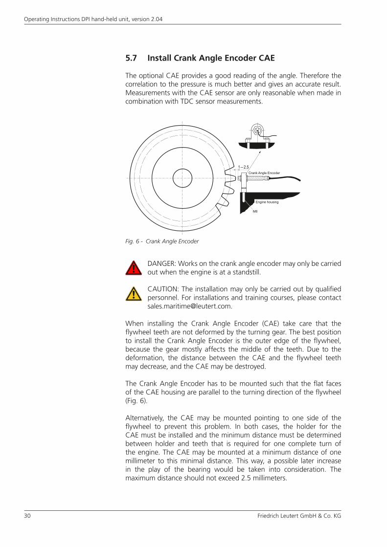
Fig. 6 - Crank Angle Encoder
5.7 Install Crank Angle Encoder CAE
The optional CAE provides a good reading of the angle. Therefore the correlation to the pressure is much better and gives an accurate result. Measurements with the CAE sensor are only reasonable when made in combination with TDC sensor measurements.
When installing the Crank Angle Encoder (CAE) take care that the flywheel teeth are not deformed by the turning gear. The best position to install the Crank Angle Encoder is the outer edge of the flywheel, because the gear mostly affects the middle of the teeth. Due to the deformation, the distance between the CAE and the flywheel teeth may decrease, and the CAE may be destroyed.
The Crank Angle Encoder has to be mounted such that the flat faces of the CAE housing are parallel to the turning direction of the flywheel (Fig. 6).
Alternatively, the CAE may be mounted pointing to one side of the flywheel to prevent this problem. In both cases, the holder for the CAE must be installed and the minimum distance must be determined between holder and teeth that is required for one complete turn of the engine. The CAE may be mounted at a minimum distance of one millimeter to this minimal distance. This way, a possible later increase in the play of the bearing would be taken into consideration. The maximum distance should not exceed 2.5 millimeters.
DANGER: Works on the crank angle encoder may only be carried out when the engine is at a standstill.
CAUTION: The installation may only be carried out by qualified personnel. For installations and training courses, please contact [email protected].
Friedrich Leutert GmbH & Co. KG 31
Operating Instructions DPI hand-held unit, version 2.04
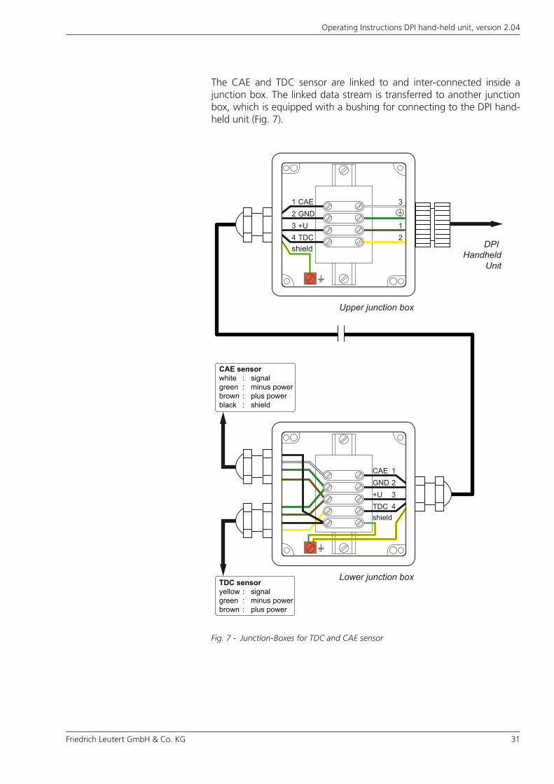
The CAE and TDC sensor are linked to and inter-connected inside a junction box. The linked data stream is transferred to another junction box, which is equipped with a bushing for connecting to the DPI hand-held unit (Fig. 7).
Fig. 7 - Junction-Boxes for TDC and CAE sensor
Upper junction box
Lower junction box
DPI Handheld
Unit
CAEGND+UTDC
1234
1
3
2
shield
shield
CAEGND+UTDC
1234
CAE sensorwhite : signalgreen : minus powerbrown : plus powerblack : shield
TDC sensoryellow : signalgreen : minus powerbrown : plus power
32 Friedrich Leutert GmbH & Co. KG
Operating Instructions DPI hand-held unit, version 2.04
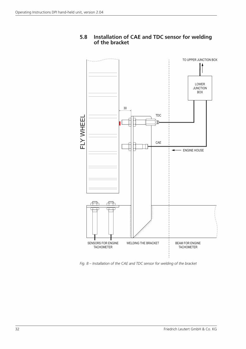
5.8 Installation of CAE and TDC sensor for welding of the bracket
Fig. 8 – Installation of the CAE and TDC sensor for welding of the bracket
FLY
WH
EE
L
SENSORS FOR ENGINETACHOMETER
WELDING THE BRACKET BEAM FOR ENGINETACHOMETER
ENGINE HOUSE
LOWERJUNCTION
BOX
TDC
30
CAE
TO UPPER JUNCTION BOX
Friedrich Leutert GmbH & Co. KG 33
Operating Instructions DPI hand-held unit, version 2.04
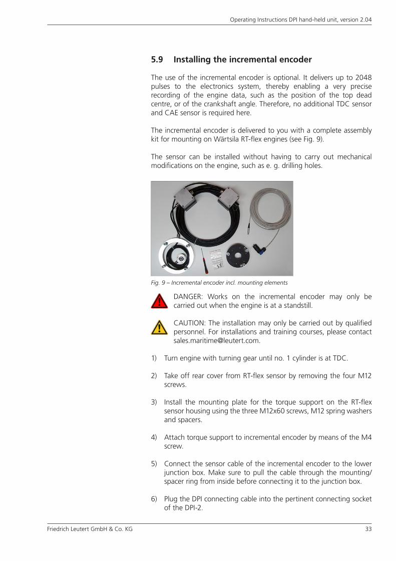
5.9 Installing the incremental encoder
The use of the incremental encoder is optional. It delivers up to 2048 pulses to the electronics system, thereby enabling a very precise recording of the engine data, such as the position of the top dead centre, or of the crankshaft angle. Therefore, no additional TDC sensor and CAE sensor is required here.
The incremental encoder is delivered to you with a complete assembly kit for mounting on Wärtsila RT-flex engines (see Fig. 9).
The sensor can be installed without having to carry out mechanical modifications on the engine, such as e. g. drilling holes.
1) Turn engine with turning gear until no. 1 cylinder is at TDC.
2) Take off rear cover from RT-flex sensor by removing the four M12 screws.
3) Install the mounting plate for the torque support on the RT-flex sensor housing using the three M12x60 screws, M12 spring washers and spacers.
4) Attach torque support to incremental encoder by means of the M4 screw.
5) Connect the sensor cable of the incremental encoder to the lower junction box. Make sure to pull the cable through the mounting/spacer ring from inside before connecting it to the junction box.
6) Plug the DPI connecting cable into the pertinent connecting socket of the DPI-2.
Fig. 9 – Incremental encoder incl. mounting elements
DANGER: Works on the incremental encoder may only be carried out when the engine is at a standstill.
CAUTION: The installation may only be carried out by qualified personnel. For installations and training courses, please contact [email protected].
34 Friedrich Leutert GmbH & Co. KG
Operating Instructions DPI hand-held unit, version 2.04
7) Switch on the DPI hand-held unit and switch to the configuration menu as described in the adjacent text.
8) Now turn the incremental encoder by hand until ‚TDC signal on‘ is shown in the display of the DPI handheld unit, using the red mark on the incremental encoder for orientation. This procedure may take some time and requires a steady hand.
9) When the correct position has been reached, slide the incremental encoder over the 10 mm diameter shaft protruding from the RT-flex sensor.
10) Attach the torque support to the mounting plate using the M6 screw.
11) Subsequently, readjust the incremental encoder, if required (see step 8). To assist turning, you may insert an Allen key into one of the mounting bolts of the incremental encoder. Observe the display of the DPI hand-held unit.
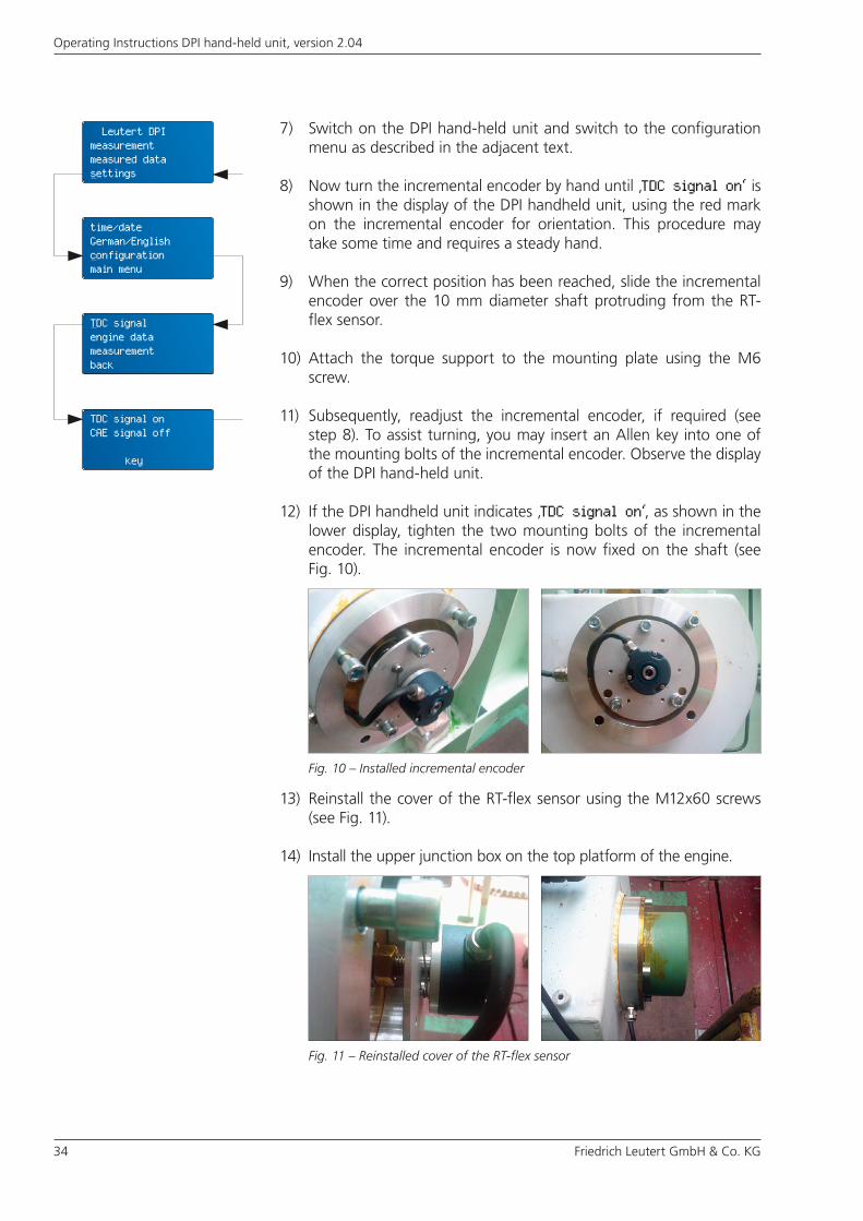
12) If the DPI handheld unit indicates ‚TDC signal on‘, as shown in the lower display, tighten the two mounting bolts of the incremental encoder. The incremental encoder is now fixed on the shaft (see Fig. 10).
13) Reinstall the cover of the RT-flex sensor using the M12x60 screws (see Fig. 11).
14) Install the upper junction box on the top platform of the engine.
Fig. 10 – Installed incremental encoder
Fig. 11 – Reinstalled cover of the RT-flex sensor
Leutert DPImeasurementmeasured datasettings
time/dateGerman/Englishconfigurationmain menu
TDC signalengine datameasurementback
TDC signal onCAE signal off
key
Friedrich Leutert GmbH & Co. KG 35
Operating Instructions DPI hand-held unit, version 2.04
5.10 Installing the Alpha Lubricator connection kit
The use of the Leutert Alpha Lubricator connection kit (in the following referred to as Leutert connection kit) is optional and suitable exclusively for engines equipped with an MAN Alpha Lubricator System. It enables the use of the incremental encoder already standard installed with the MAN Alpha Lubricator without impairing its function. For this purpose, neither an additional incremental encoder, nor TDC or CAE sensors are required.
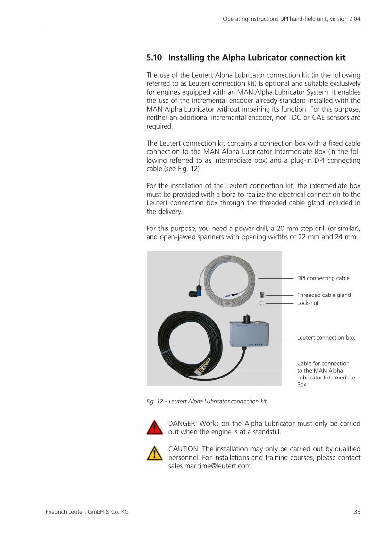
The Leutert connection kit contains a connection box with a fixed cable connection to the MAN Alpha Lubricator Intermediate Box (in the fol-lowing referred to as intermediate box) and a plug-in DPI connecting cable (see Fig. 12).
For the installation of the Leutert connection kit, the intermediate box must be provided with a bore to realize the electrical connection to the Leutert connection box through the threaded cable gland included in the delivery.
For this purpose, you need a power drill, a 20 mm step drill (or similar), and open-jawed spanners with opening widths of 22 mm and 24 mm.
Fig. 12 – Leutert Alpha Lubricator connection kit
DANGER: Works on the Alpha Lubricator must only be carried out when the engine is at a standstill.
CAUTION: The installation may only be carried out by qualified personnel. For installations and training courses, please contact [email protected].
Leutert connection box
Cable for connection to the MAN Alpha Lubricator Intermediate Box
DPI connecting cable
Threaded cable glandLock-nut

36 Friedrich Leutert GmbH & Co. KG
Operating Instructions DPI hand-held unit, version 2.04
Fig. 13 – MAN Alpha Lubricator Intermediate Box
Fig. 14 – Leutert connection box
1) Fasten the Leutert connection box by means of the mounting bracket on the motor level of the cylinders. Place it in such a way that the connected cables can easily reach each of the cylinders during pressure measurement by means of the DPI handheld unit.
2) Lay the black connecting cable to the intermediate box. If required, shorten the cable to the proper length. Allow for sufficient reserve for cabling inside the intermediate box.
3) Open the MAN intermediate box (see Fig. 13), and measure the voltage supply between the terminals „+E Volt” (red cable) and „GND (0V)” (blue cable).
In the rare event that the voltage supply should be at 5 V, please reconnect the three white signal cables in the Leutert connection box from the lower right to the lower left clamping strip designated „5 V” (see Fig. 14). In doing so, pay attention to the color coding of the individual terminals.
red: +E Volt
blue: GND (0 V)
white: CAE inverted
purple: TDC inverted
Friedrich Leutert GmbH & Co. KG 37
Operating Instructions DPI hand-held unit, version 2.04
4) Disconnect the intermediate box from the power supply. This can also be achieved by disconnecting the supply voltage „+E Volt”.
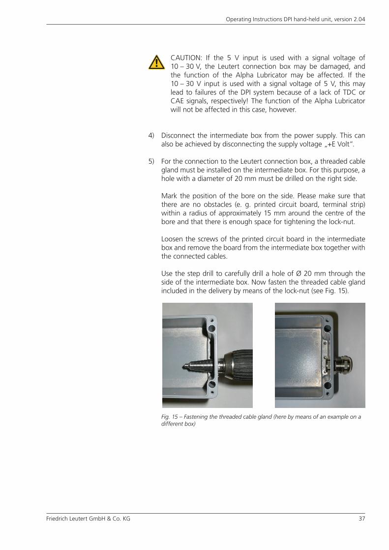
5) For the connection to the Leutert connection box, a threaded cable gland must be installed on the intermediate box. For this purpose, a hole with a diameter of 20 mm must be drilled on the right side.
Mark the position of the bore on the side. Please make sure that there are no obstacles (e. g. printed circuit board, terminal strip) within a radius of approximately 15 mm around the centre of the bore and that there is enough space for tightening the lock-nut.
Loosen the screws of the printed circuit board in the intermediate box and remove the board from the intermediate box together with the connected cables.
Use the step drill to carefully drill a hole of Ø 20 mm through the side of the intermediate box. Now fasten the threaded cable gland included in the delivery by means of the lock-nut (see Fig. 15).
CAUTION: If the 5 V input is used with a signal voltage of 10 – 30 V, the Leutert connection box may be damaged, and the function of the Alpha Lubricator may be affected. If the 10 – 30 V input is used with a signal voltage of 5 V, this may lead to failures of the DPI system because of a lack of TDC or CAE signals, respectively! The function of the Alpha Lubricator will not be affected in this case, however.
Fig. 15 – Fastening the threaded cable gland (here by means of an example on a different box)
38 Friedrich Leutert GmbH & Co. KG
Operating Instructions DPI hand-held unit, version 2.04
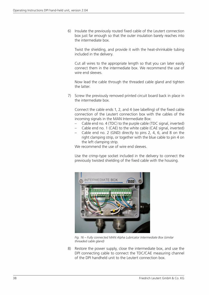
7) Screw the previously removed printed circuit board back in place in the intermediate box.
Connect the cable ends 1, 2, and 4 (see labelling) of the fixed cable connection of the Leutert connection box with the cables of the incoming signals in the MAN Intermediate Box: – Cable end no. 4 (TDC) to the purple cable (TDC signal, inverted)– Cable end no. 1 (CAE) to the white cable (CAE signal, inverted)– Cable end no. 2 (GND) directly to pins 2, 4, 6, and 8 on the
right clamping strip, or together with the blue cable to pin 4 on the left clamping strip.
We recommend the use of wire end sleeves.
Use the crimp-type socket included in the delivery to connect the previously twisted shielding of the fixed cable with the housing.
Fig. 16 – Fully connected MAN Alpha Lubricator Intermediate Box (similar threaded cable gland)
8) Restore the power supply, close the intermediate box, and use the DPI connecting cable to connect the TDC/CAE measuring channel of the DPI handheld unit to the Leutert connection box.
6) Insulate the previously routed fixed cable of the Leutert connection box just far enough so that the outer insulation barely reaches into the intermediate box.
Twist the shielding, and provide it with the heat-shrinkable tubing included in the delivery.
Cut all wires to the appropriate length so that you can later easily connect them in the intermediate box. We recommend the use of wire end sleeves.
Now lead the cable through the threaded cable gland and tighten the latter.
Friedrich Leutert GmbH & Co. KG 39
Operating Instructions DPI hand-held unit, version 2.04
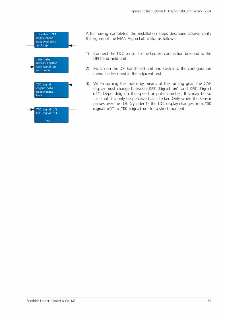
After having completed the installation steps described above, verify the signals of the MAN Alpha Lubricator as follows:
1) Connect the TDC sensor to the Leutert connection box and to the DPI hand-held unit.
2) Switch on the DPI hand-held unit and switch to the configuration menu as described in the adjacent text.
3) When turning the motor by means of the turning gear, the CAE display must change between ‚CAE Signal on‘ and ‚CAE Signal off‘. Depending on the speed or pulse number, this may be so fast that it is only be perceived as a flicker. Only when the sensor passes over the TDC (cylinder 1), the TDC display changes from ‚TDC signal off‘ to ‚TDC signal on‘ for a short moment.
Leutert DPImeasurementmeasured datasettings
time/dateGerman/Englishconfigurationmain menu
TDC signalengine datameasurementback
TDC signal offCAE signal off
key
40 Friedrich Leutert GmbH & Co. KG
Operating Instructions DPI hand-held unit, version 2.04
Then fasten the pressure sensor at the indication bore of the engine. When starting the measurements, tighten the initially cold sensor only slightly in order to prevent it from seizing.
Measuring conditionsBefore beginning the test series, check whether the TDC is configured correctly (chapter 5.3), the data memory has been deleted (chapter 5.4) and the measuring settings (chapter 5.5) are applicable.
To achieve comparable results, ensure that the load remains as stable and the number of RPM of the engine as constant as possible during the measuring. If, for example, a TDC sensor with activated averaging is used when the load and RPM vary, this may cause additional angle errors in the depiction of the TDC position.
Note down engine settings and operating conditions in order to reproduce them for later measuring.
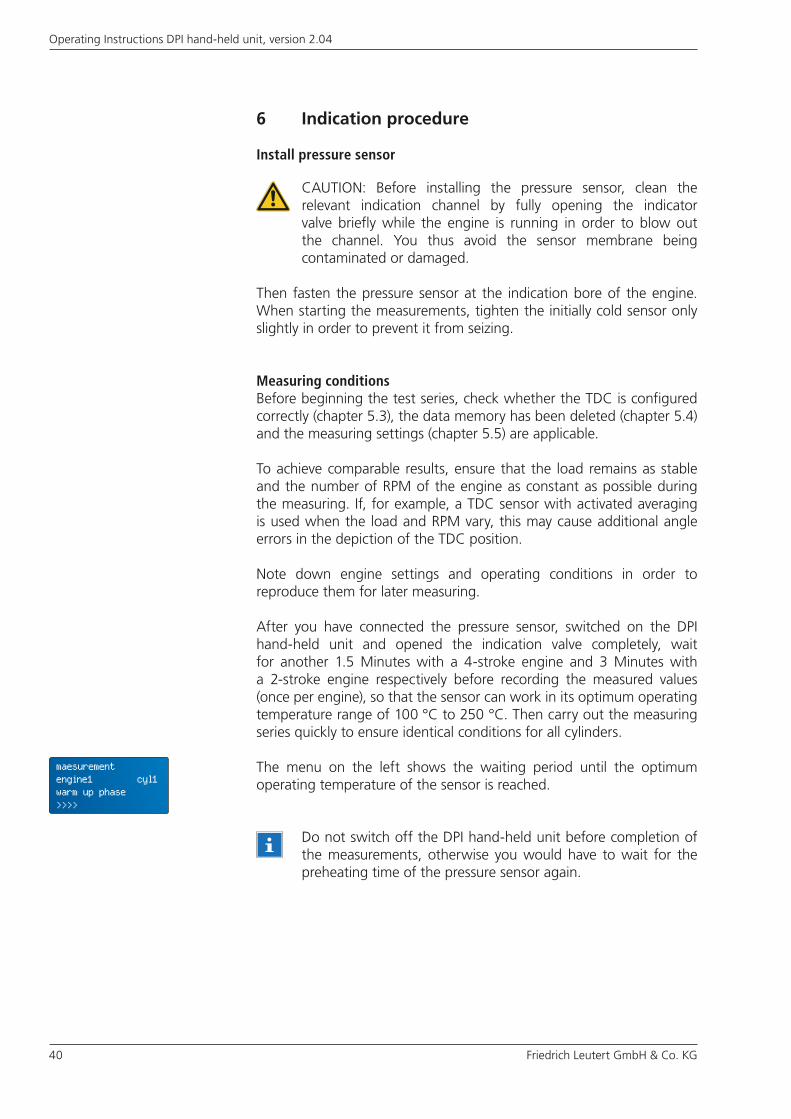
After you have connected the pressure sensor, switched on the DPI hand-held unit and opened the indication valve completely, wait for another 1.5 Minutes with a 4-stroke engine and 3 Minutes with a 2-stroke engine respectively before recording the measured values (once per engine), so that the sensor can work in its optimum operating temperature range of 100 °C to 250 °C. Then carry out the measuring series quickly to ensure identical conditions for all cylinders.
The menu on the left shows the waiting period until the optimum operating temperature of the sensor is reached.
6 Indication procedure
Install pressure sensor
Do not switch off the DPI hand-held unit before completion of the measurements, otherwise you would have to wait for the preheating time of the pressure sensor again.
CAUTION: Before installing the pressure sensor, clean the relevant indication channel by fully opening the indicator valve briefly while the engine is running in order to blow out the channel. You thus avoid the sensor membrane being contaminated or damaged.
maesurementengine1 cyl1warm up phase>>>>
Friedrich Leutert GmbH & Co. KG 41
Operating Instructions DPI hand-held unit, version 2.04
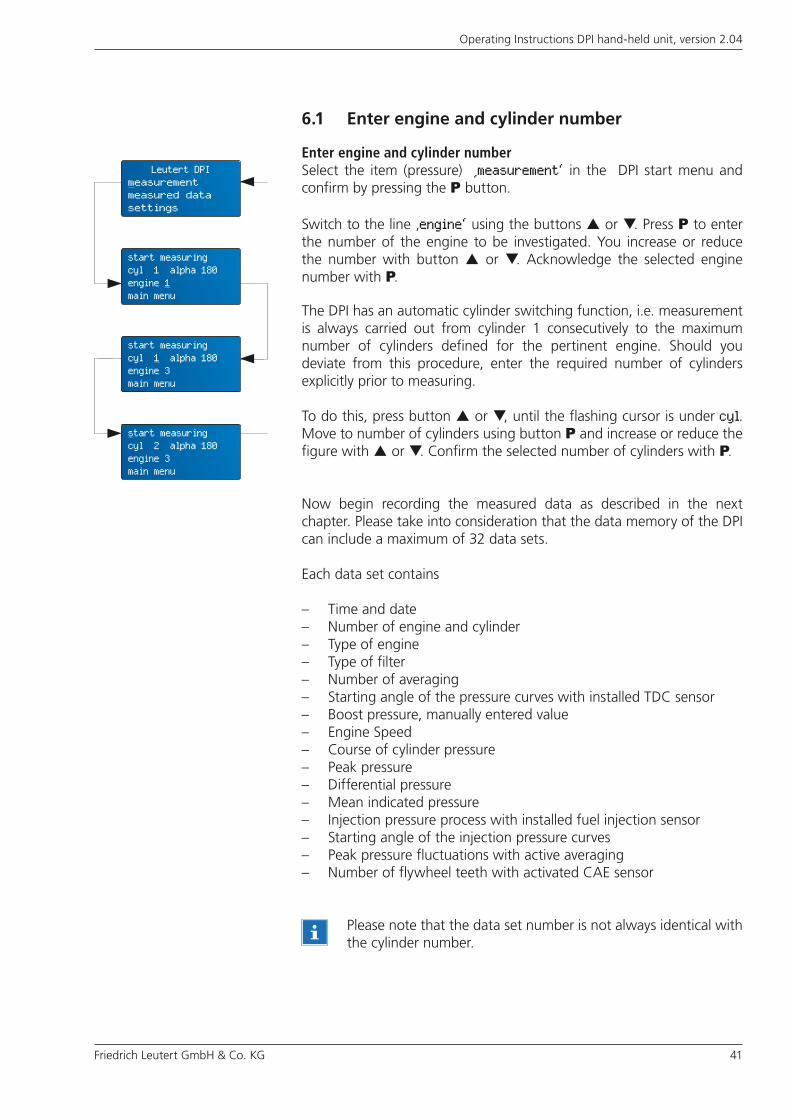
Enter engine and cylinder numberSelect the item (pressure) ‚measurement‘ in the DPI start menu and confirm by pressing the P button.
Switch to the line ‚engine‘ using the buttons or . Press P to enter the number of the engine to be investigated. You increase or reduce the number with button or . Acknowledge the selected engine number with P.
The DPI has an automatic cylinder switching function, i.e. measurement is always carried out from cylinder 1 consecutively to the maximum number of cylinders defined for the pertinent engine. Should you deviate from this procedure, enter the required number of cylinders explicitly prior to measuring.
To do this, press button or , until the flashing cursor is under cyl. Move to number of cylinders using button P and increase or reduce the figure with or . Confirm the selected number of cylinders with P.
Now begin recording the measured data as described in the next chapter. Please take into consideration that the data memory of the DPI can include a maximum of 32 data sets.
Each data set contains
– Time and date– Number of engine and cylinder– Type of engine– Type of filter– Number of averaging– Starting angle of the pressure curves with installed TDC sensor– Boost pressure, manually entered value– Engine Speed– Course of cylinder pressure– Peak pressure– Differential pressure– Mean indicated pressure– Injection pressure process with installed fuel injection sensor– Starting angle of the injection pressure curves – Peak pressure fluctuations with active averaging– Number of flywheel teeth with activated CAE sensor
6.1 Enter engine and cylinder number
Please note that the data set number is not always identical with the cylinder number.
Leutert DPImeasurementmeasured datasettings
start measuringcyl 1 alpha 180engine 1main menu
start measuringcyl 1 alpha 180engine 3main menu
start measuringcyl 2 alpha 180engine 3main menu
42 Friedrich Leutert GmbH & Co. KG
Operating Instructions DPI hand-held unit, version 2.04
6.2 Record measured data
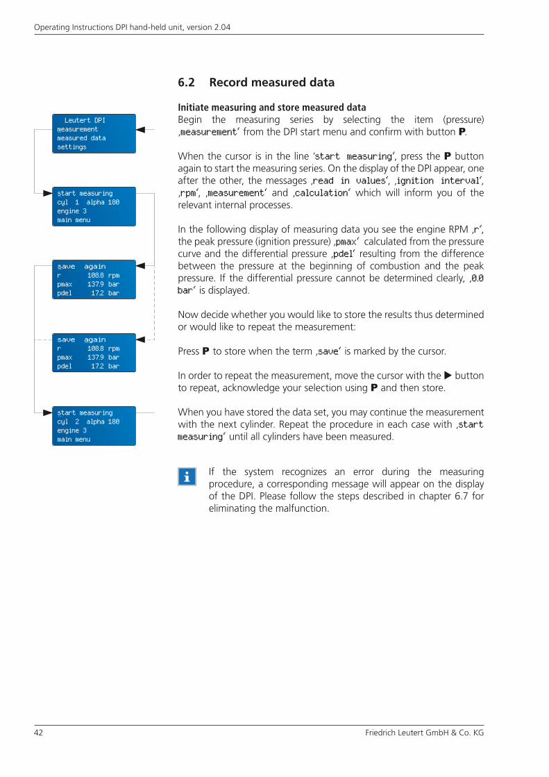
Initiate measuring and store measured dataBegin the measuring series by selecting the item (pressure) ‚measurement‘ from the DPI start menu and confirm with button P.
When the cursor is in the line ‘start measuring‘, press the P button again to start the measuring series. On the display of the DPI appear, one after the other, the messages ‚read in values‘, ‚ignition interval‘, ‚rpm‘, ‚measurement‘ and ‚calculation‘ which will inform you of the relevant internal processes.
In the following display of measuring data you see the engine RPM ‚r‘, the peak pressure (ignition pressure) ‚pmax‘ calculated from the pressure curve and the differential pressure ‚pdel‘ resulting from the difference between the pressure at the beginning of combustion and the peak pressure. If the differential pressure cannot be determined clearly, ‚0.0 bar‘ is displayed.
Now decide whether you would like to store the results thus determined or would like to repeat the measurement:
Press P to store when the term ‚save‘ is marked by the cursor.
In order to repeat the measurement, move the cursor with the button to repeat, acknowledge your selection using P and then store.
When you have stored the data set, you may continue the measurement with the next cylinder. Repeat the procedure in each case with ‚start measuring‘ until all cylinders have been measured.
If the system recognizes an error during the measuring procedure, a corresponding message will appear on the display of the DPI. Please follow the steps described in chapter 6.7 for eliminating the malfunction.
Leutert DPImeasurementmeasured datasettings
start measuringcyl 1 alpha 180engine 3main menu
save againr 108.8 rpm pmax 137.9 barpdel 17.2 bar
save againr 108.8 rpm pmax 137.9 barpdel 17.2 bar
start measuringcyl 2 alpha 180engine 3main menu

Friedrich Leutert GmbH & Co. KG 43
Operating Instructions DPI hand-held unit, version 2.04
Overwrite measured dataIf the message ‚memory full‘ appears in the display when data is being stored this means the storage allocation has reached 32 data sets. You do not have to interrupt indication in every case, but it is possible to overwrite existing older data by the new. Please pay attention to the advice below.
Scroll down with the button to get additional information about the measurement. This information is only available if the options are enabled.
The command ‚replace‘ is marked by the cursor. Confirm with P if you want to overwrite a data set. You also have the option to prevent overwriting by selecting ‚abort‘. Switch to this term with the button and acknowledge with P. The most recent data is not stored.
Select the data set number to be overwritten using or buttons and press P. This stores the last measured data under this number. You can abort the procedure by selecting ‚no 0‘, i.e. the most recent data is not stored.
If you continue the indication at this point by means of ‚start measuring‘ the message ‚memory full‘ will appear again. Either overwrite existing data sets again or start the measuring series from the beginning, but delete the whole data memory beforehand.
Overwriting data sets involves the difficulty that data sets of the same engine recorded at different dates are mixed. This causes an untidy measuring series. It is always better to delete the data memory completely or the individual engine data before recording a new measuring series, refer to chapter 5.4.
save againr 108.8 rpm pmax 137.9 barpdel 17.2 bar
save againpinj 691.5 barmip 16.1 barPow 1884 kW
memory full
replace abort
replace no. 8engine 1 cyl 2time [09:53:26]date [26-02-08]
start measuringcyl 2 Alpha 180engine 1main menu
44 Friedrich Leutert GmbH & Co. KG
Operating Instructions DPI hand-held unit, version 2.04
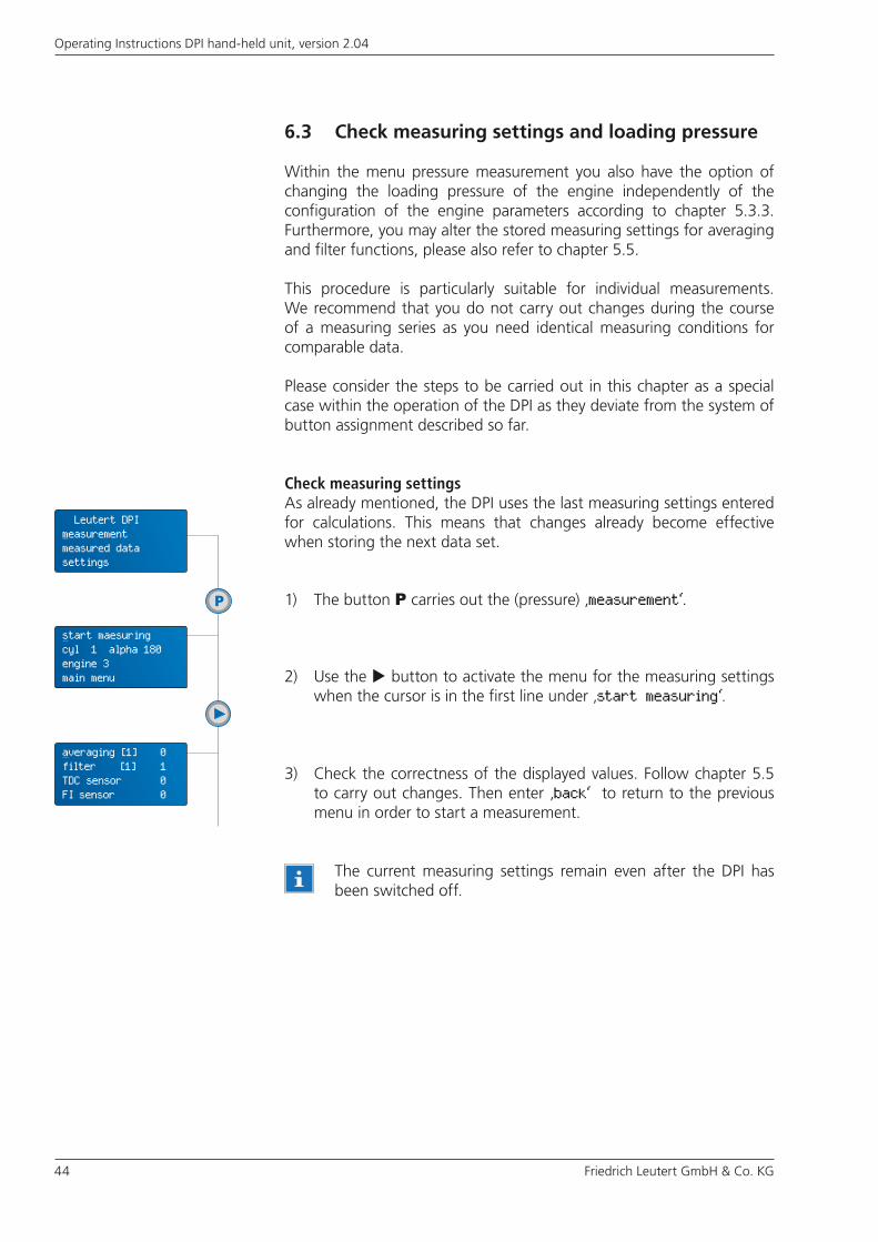
6.3 Check measuring settings and loading pressure
Within the menu pressure measurement you also have the option of changing the loading pressure of the engine independently of the configuration of the engine parameters according to chapter 5.3.3. Furthermore, you may alter the stored measuring settings for averaging and filter functions, please also refer to chapter 5.5.
This procedure is particularly suitable for individual measurements. We recommend that you do not carry out changes during the course of a measuring series as you need identical measuring conditions for comparable data.
Please consider the steps to be carried out in this chapter as a special case within the operation of the DPI as they deviate from the system of button assignment described so far.
Check measuring settingsAs already mentioned, the DPI uses the last measuring settings entered for calculations. This means that changes already become effective when storing the next data set.
2) Use the button to activate the menu for the measuring settings when the cursor is in the first line under ‚start measuring‘.
1) The button P carries out the (pressure) ‚measurement‘.
3) Check the correctness of the displayed values. Follow chapter 5.5 to carry out changes. Then enter ‚back‘ to return to the previous menu in order to start a measurement.
The current measuring settings remain even after the DPI has been switched off.
start maesuringcyl 1 alpha 180engine 3main menu
Leutert DPImeasurementmeasured datasettings
averaging [1] 0 filter [1] 1TDC sensor 0FI sensor 0
Friedrich Leutert GmbH & Co. KG 45
Operating Instructions DPI hand-held unit, version 2.04
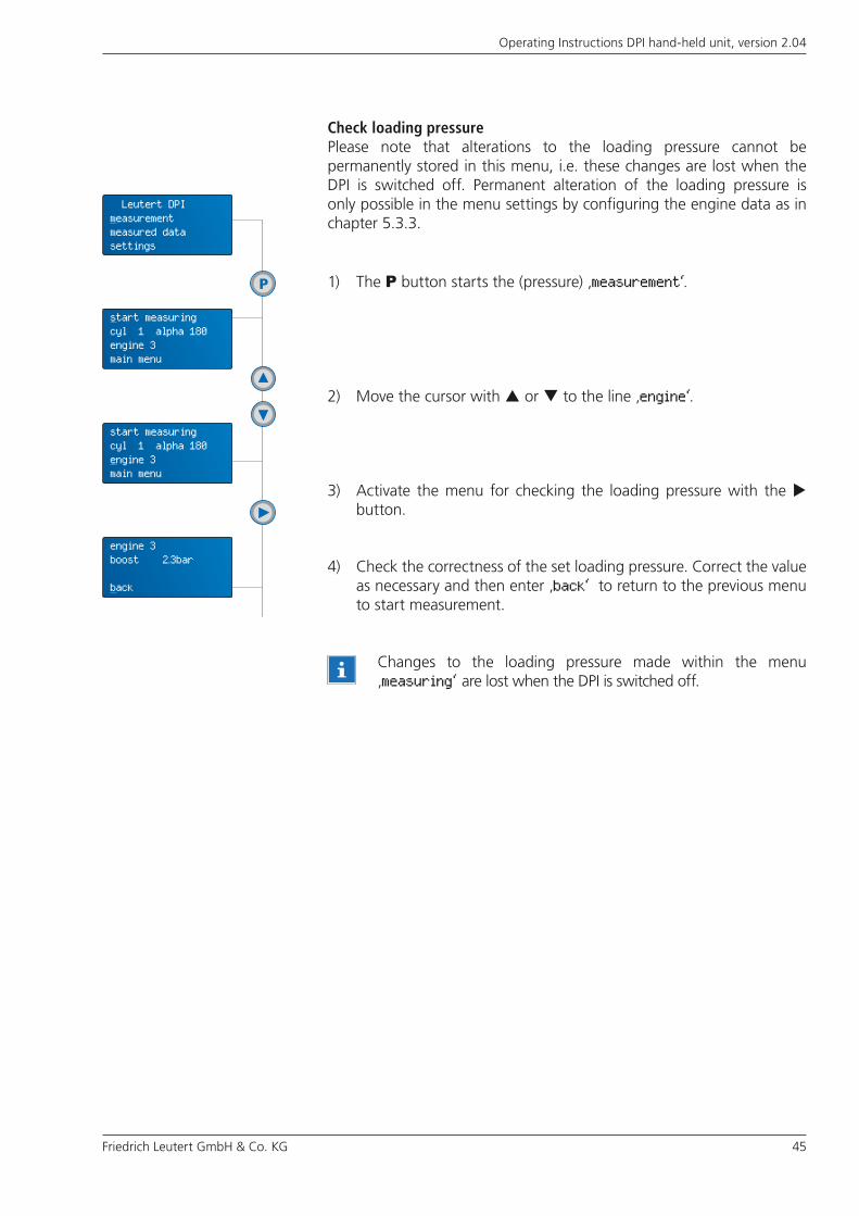
Check loading pressurePlease note that alterations to the loading pressure cannot be permanently stored in this menu, i.e. these changes are lost when the DPI is switched off. Permanent alteration of the loading pressure is only possible in the menu settings by configuring the engine data as in chapter 5.3.3.
3) Activate the menu for checking the loading pressure with the button.
4) Check the correctness of the set loading pressure. Correct the value as necessary and then enter ‚back‘ to return to the previous menu to start measurement.
2) Move the cursor with or to the line ‚engine‘.
Changes to the loading pressure made within the menu ‚measuring‘ are lost when the DPI is switched off.
1) The P button starts the (pressure) ‚measurement‘.
start measuringcyl 1 alpha 180engine 3main menu
Leutert DPImeasurementmeasured datasettings
start measuringcyl 1 alpha 180engine 3main menu
engine 3boost 2.3bar
back

46 Friedrich Leutert GmbH & Co. KG
Operating Instructions DPI hand-held unit, version 2.04
If you want the alpha values, which were changed during the measuring procedure, to be stored permanently, switch to the configuration menu for the engine data after finishing the indication without switching off the DPI. If you store the TDC offset here, it will not be lost when the DPI hand-held unit is switched off.
6.4 Automatic recognition of alpha value
If a TDC sensor has been connected, the DPI automatically determines the TDC offset (alpha) of the cylinder currently being indicated during the measuring procedure and compares it to the value configured for this cylinder. In order to prevent incorrect measurements, the DPI signals differences of more than 16° shaft with the message ‚wrong alphavalue‘.
Please, decide whether you want to change the TDC offset or continue measuring with the previous value:
If you want to continue measuring with the configured value move to ‚continue‘ with the button and acknowledge with P.
To make corrections, press button P, when the command ‚change‘ is marked.
If the cursor is marking the word ‚alpha‘, press the P button in order to be able to change the alpha value using or . If the correct ignition interval has been set, terminate this menu with P and continue the measuring series. Please note that this alteration is lost when the system is switched off.
Supplementary explanationsWith the defined trigger level of 30 % peak pressure and the correlated crank angle of -25 °CA, the ignition interval related is determined. This is a control function to verify the entered angles for the TDCs.
If the criteria is exceeded, the calculated angle will be displayed and can be accepted or modified by the user. The maximum error of the calculation may be ± 8 °CA. Please regard the measured apha values only as an orientation.
wrong alphavalue180 CA check:cylinder numberchange continue
engine 1cylinder 12alpha 180.0back
start measuringcyl 12 alpha 120engine 1main menu
Friedrich Leutert GmbH & Co. KG 47
Operating Instructions DPI hand-held unit, version 2.04
Leave the DPI hand-held unit switched on if you wish to index several engines in succession in order to avoid unnecessary warm-up phases of the device.
If the pressure sensor cannot be screwed off, open the indicator valve for a short time in order to release combustion pressure. Be sure to close valve immediately after removing the sensor. Afterwards the pressure sensor can be unscrewed.
6.5 Complete measuring series and remove pressure sensor
Do not forget to switch off the DPI hand-held unit after every use to relieve the battery. After 10 minutes of standby the DPI hand-held unit turns off automatically.
CAUTION: After completion of the measuring series, remove the pressure sensor from the indication bore in order to avoid overheating. To do this use the box spanner supplied.
Pull the connecting cable out of the DPI hand-held unit and keep those system components in the carrying case which are supposed to be stored there.
Observe the safety advice in chapter 2.

48 Friedrich Leutert GmbH & Co. KG
Operating Instructions DPI hand-held unit, version 2.04
6.6 Display measuring results
6.6.1 View data sets at the DPI
Even during the recording of measured values, some of the data determined may be seen on the DPI display such as RPM, peak and differential pressure. The complete data sets may be viewed independently of the measuring location on the DPI hand-held unit on conclusion of the measuring series.
Switch on the DPI and move to the menu ‚measured data‘.
Select the function ‚view‘.
The data set number is marked by the cursor. Switch through all existing data sets with the buttons or and view the stored measured values:
– Data set number, time, date (day-month)– Engine and cylinder number– Peak pressure pmax [bar], differential pressure pdel [bar]– Engine speed r [RPM] , mean indicated pressure [bar]
You may exit this menu at any data set number using the P button.
Please, switch off the DPI hand-held unit.
6.6.2 Transfer data sets to PC
Use the DPI software which is part of the system for analyzing and interpreting the recorded course of cylinder pressure. To do so, it is necessary to transfer the stored data sets to the PC.
Please see chapter 5 of the DPI software manual for the process of the data communication and evaluation.
Leutert DPImeasurementmeasured datasettings
viewsenddeletemain menu
no 4 14:50 21-09engine 1 cyl 16pmax 77 pdel 34r 746 mip 16.1
viewsenddeletemain menu
Friedrich Leutert GmbH & Co. KG 49
Operating Instructions DPI hand-held unit, version 2.04
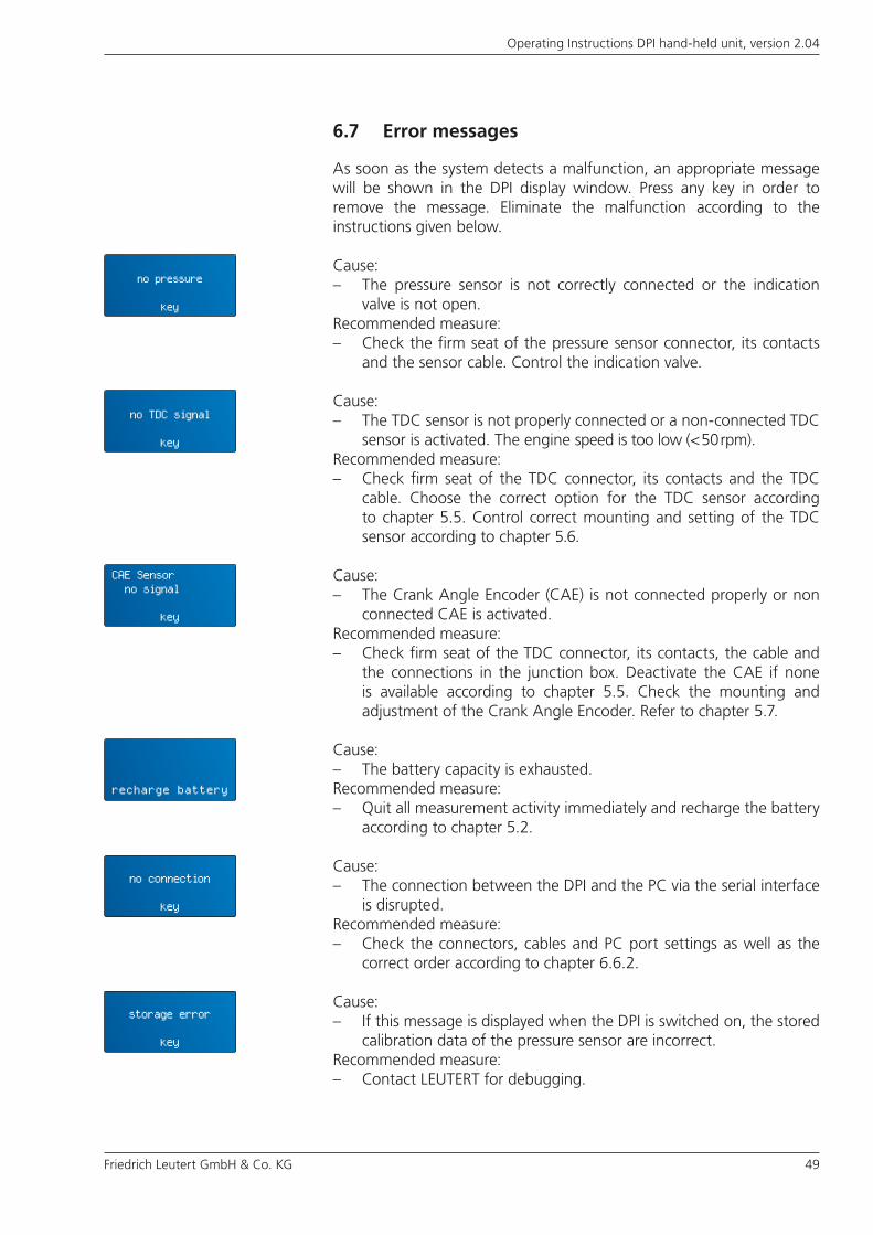
6.7 Error messages
As soon as the system detects a malfunction, an appropriate message will be shown in the DPI display window. Press any key in order to remove the message. Eliminate the malfunction according to the instructions given below.
Cause: – The pressure sensor is not correctly connected or the indication
valve is not open.Recommended measure:– Check the firm seat of the pressure sensor connector, its contacts
and the sensor cable. Control the indication valve.
Cause:– The TDC sensor is not properly connected or a non-connected TDC
sensor is activated. The engine speed is too low (< 50 rpm).Recommended measure:– Check firm seat of the TDC connector, its contacts and the TDC
cable. Choose the correct option for the TDC sensor according to chapter 5.5. Control correct mounting and setting of the TDC sensor according to chapter 5.6.
Cause:– The Crank Angle Encoder (CAE) is not connected properly or non
connected CAE is activated.Recommended measure:– Check firm seat of the TDC connector, its contacts, the cable and
the connections in the junction box. Deactivate the CAE if none is available according to chapter 5.5. Check the mounting and adjustment of the Crank Angle Encoder. Refer to chapter 5.7.
Cause:– The battery capacity is exhausted.Recommended measure:– Quit all measurement activity immediately and recharge the battery
according to chapter 5.2.
Cause:– The connection between the DPI and the PC via the serial interface
is disrupted.Recommended measure:– Check the connectors, cables and PC port settings as well as the
correct order according to chapter 6.6.2.
Cause:– If this message is displayed when the DPI is switched on, the stored
calibration data of the pressure sensor are incorrect.Recommended measure:– Contact LEUTERT for debugging.
no pressure
key
no TDC signal
key
CAE Sensor no signal
key
recharge battery
no connection
key
storage error
key
50 Friedrich Leutert GmbH & Co. KG
Operating Instructions DPI hand-held unit, version 2.04
6.8 Warnings
Warnings indicate that undesirable or faulty results may occur during further use of the device. Press any key to remove the message, and carry out the recommended measures.
Meaning:– The automatically measured TDC offset does not match the stored
value.
Cause:– The cylinder number selected at the DPI hand-held unit does not
match the measured cylinder.Recommended measure:– Correct the cylinder number manually at the DPI hand-held unit
and repeat the measurement.
Cause:– The indication valve is not opened correctly and/or defective.Recommended measure:– Please ensure that the indicating valve is completely opened
and then continue the measurement. Check the valve after the measurement and replace it if necessary.
Cause:– There are no data stored under the chosen engine number.Recommended measure:– Choose the correct engine number.
Cause:– The menu for changing the engine parameters or measurement
settings, respectively, is locked. You are not authorized to change the values previously transmitted to the DPI hand-held unit via the DPI software (starting from version 3.24).
Recommended measure:– The menu can only be enabled by means of a password via the DPI
software by the person responsible for measurements
Cause:– The data memory is completely filled.Recommended measure:– Delete the data memory according to chapter 5.4 before starting
the measurement or overwrite existing data sets during the measuring series according to chapter 6.2.
menue lockedback
wrong alphavalue180 CA check:cylinder numberchange continue
no data
key
memory full
replace abort

Friedrich Leutert GmbH & Co. KG 51
Operating Instructions DPI hand-held unit, version 2.04
7.2 Cleaning of the sensors
Cleaning of the pressure sensorRemove regularly any soot or carbon deposits from the pressure sensor since they might interfere with the measuring operation. The contamination rate depends on the indicated engine and its operating conditions. The cleaning intervals given below should, thus, be considered as a rough guide:
– after some 5 operating hours for a diesel engine running on heavy fuel
– after some 30 operating hours for an diesel engine running on diesel oil
When using the equipment on gas driven engines, cleaning is not required.
No warranty claims will be accepted for damage or destruction of the pressure sensor due to non-respect of the following safety instruction.
While the calibration settings are controlled at LEUTERT, the pressure sensor will be cleaned simultaneously.
7 Maintenance
7.1 Maintenance of the pressure sensor
The DPI hand-held unit is maintenance-free. Make sure that the device and the pertaining pressure sensor are returned to the company Leutert for control of the calibration data after approx. 100 operating hours or after 3 years, respectively.
CAUTION:
– Before cleaning, allow the sensor to cool down to less than 50 °C.– Use commercial cleaning agent.– Do not introduce any tools into the sensor bore.– Do not disassemble the sensor unit.– Wear safety glasses when blowing out the sensor bore.
For cleaning the pressure sensor proceed as follows:
1) Fix the sensor unit in upright position, with the sensor access bore pointing upwards.
2) Pour the cleaning liquid in a mixture ratio of 1:10 into the sensor bore and allow to react for about 30 min. to 1 hour.
3) Remove the introduced cleaning agent by turning the device upside down.

52 Friedrich Leutert GmbH & Co. KG
Operating Instructions DPI hand-held unit, version 2.04
Cleaning of the TDC sensor and the CAEFor a perfect operation, remove oil and dirt from the TDC sensor and Crank Angle Encoder.
– Do not use any aggressive cleaning agents such as e. g. cleaner’s naphtha.
DANGER: This work must be done only when the engine is stopped!
7.3 Changing the battery pack
When the battery pack needs to be changed or removed, follow the steps below:
1) Unscrew the front-end lid by means of the provided hex wrench. Afterwards pull out the battery pack (see Fig. 17).
2) Press the latch lock and pull the connection plug from the battery pack (see Fig. 18).
CAUTION: Switch off the DPI hand-held unit and disconnect the charger before beginning the procedure.
To install the battery pack please follow the steps in reverse order.
Fig. 17 – Remove storage battery Fig. 18 – Pull connecting plug
4) Afterwards, blow out the sensor bore by means of compressed air (max. 4 bar).
5) Any remaining cleaning agent may be removed with clear water by repeating steps 3 and 4.
If the sensor is heavily stained repeat the cleaning procedure.
Friedrich Leutert GmbH & Co. KG 53
Operating Instructions DPI hand-held unit, version 2.04
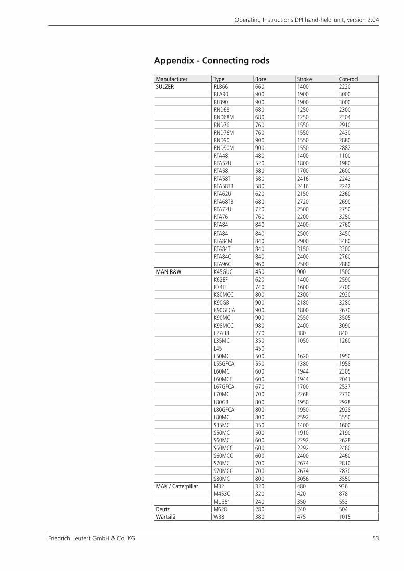
Appendix - Connecting rods
Manufacturer Type Bore Stroke Con-rodSULZER RLB66 660 1400 2220
RLA90 900 1900 3000 RLB90 900 1900 3000 RND68 680 1250 2300 RND68M 680 1250 2304 RND76 760 1550 2910 RND76M 760 1550 2430 RND90 900 1550 2880 RND90M 900 1550 2882 RTA48 480 1400 1100 RTA52U 520 1800 1980 RTA58 580 1700 2600 RTA58T 580 2416 2242 RTA58TB 580 2416 2242 RTA62U 620 2150 2360 RTA68TB 680 2720 2690 RTA72U 720 2500 2750 RTA76 760 2200 3250 RTA84 840 2400 2760
RTA84 840 2500 3450 RTA84M 840 2900 3480 RTA84T 840 3150 3300 RTA84C 840 2400 2760 RTA96C 960 2500 2880
MAN B&W K45GUC 450 900 1500 K62EF 620 1400 2590 K74EF 740 1600 2700 K80MCC 800 2300 2920 K90GB 900 2180 3280 K90GFCA 900 1800 2670 K90MC 900 2550 3505 K98MCC 980 2400 3090 L27/38 270 380 840 L35MC 350 1050 1260 L45 450L50MC 500 1620 1950 L55GFCA 550 1380 1958 L60MC 600 1944 2305 L60MCE 600 1944 2041 L67GFCA 670 1700 2537 L70MC 700 2268 2730 L80GB 800 1950 2928 L80GFCA 800 1950 2928 L80MC 800 2592 3550 S35MC 350 1400 1600 S50MC 500 1910 2190 S60MC 600 2292 2628 S60MCC 600 2292 2460 S60MCC 600 2400 2460 S70MC 700 2674 2810 S70MCC 700 2674 2870 S80MC 800 3056 3550
MAK / Catterpillar M32 320 480 936 M453C 320 420 878 MU351 240 350 553
Deutz M628 280 240 504 Wärtsilä W38 380 475 1015
54 Friedrich Leutert GmbH & Co. KG
Operating Instructions DPI hand-held unit, version 2.04
© Friedrich Leutert GmbH & Co. KG, Adendorf, 2008
This document including all of its parts is protected by copyright. Any duplication or utilization outside of the copyright law is not permitted without explicit permission from LEUTERT and may be subject to prosecution. This applies in particular to duplications of any kind, translations and incorporation into electronic systems.
– Original edition, manuals in other languages on request –
Subject to change without noticeIssued 3 April 2014


