DPMP: A Software Pattern for Real-Time Tasks Merge Rania Mzid 1,2,3 , Chokri Mraidha 1 , Asma Mehiaoui 1,2 , Sara Tucci-Piergiovanni 1 , Jean-Philippe Babau 2 , and Mohamed Abid 3 1 CEA, LIST, Laboratory of model driven engineering for embedded systems Point Courrier 174, Gif-sur-Yvette, 91191, France {rania.mzid,chokri.mraidha,asma.mehiaoui,sara.tucci@}@cea.fr 2 Lab-STICC, UBO, UEB, Brest, France {Jean-Philippe.Babau}@univ-brest.fr 3 CES Laboratory, National school of engineers of Sfax, Sfax, Tunisia {Mohamed.Abid}@enis.rnu.tn Abstract. In a model-driven development context, the refinement of the architectural model of a real-time application to a Real Time Operating System (RTOS) specific model is a challenging task. Indeed, the different design choices made to guarantee the application timing properties are not always implementable on the target RTOS. In particular, when the number of distinct priority levels used at the design level exceeds the number allowed by the RTOS for the considered application, this refine- ment becomes not possible. In this paper, we propose a software pat- tern called Distinct Priority Merge Pattern (DPMP) that automatically perform the re-factoring of the architectural model when this problem occurs. First, we give an heuristic algorithm describing this pattern and we show that this method is not always effective. Then, to address the limitations of the first method, we propose a MILP formulation of the DPMP pattern that allows to check whether a solution exists and gives the optimal one. The evaluation of the second method, allows to estimate a cost in terms of processor utilization increase during the deployment of an application on a given RTOS family characterized by the number of distinct priority levels that it offers. Keywords: Real-Time Validation, Architectural Model, RTOS-Specific Model, Software Pattern, Re-factoring, MILP Formulation; 1 Introduction In order to increase productivity and reduce the time-to-market during the de- velopment of Real-Time Embedded Systems (RTES), Model-Driven Develop- ment(MDD) proposes solutions by introducing intermediate models, from re- quirements specification to the binary code, that allows verification activities at each level of abstraction. In a software development context of such systems, the designer makes different architectural choices, at the design level, to describe the realization of the application. Then, a verification of timing properties is
3 CES Laboratory, National school of engineers of Sfax, Sfax, Tunisia{Mohamed.Abid}@enis.rnu.tn
Abstract. In a model-driven development context, the refinement of thearchitectural model of a real-time application to a Real Time OperatingSystem (RTOS) specific model is a challenging task. Indeed, the differentdesign choices made to guarantee the application timing properties arenot always implementable on the target RTOS. In particular, when thenumber of distinct priority levels used at the design level exceeds thenumber allowed by the RTOS for the considered application, this refine-ment becomes not possible. In this paper, we propose a software pat-tern called Distinct Priority Merge Pattern (DPMP) that automaticallyperform the re-factoring of the architectural model when this problemoccurs. First, we give an heuristic algorithm describing this pattern andwe show that this method is not always effective. Then, to address thelimitations of the first method, we propose a MILP formulation of theDPMP pattern that allows to check whether a solution exists and givesthe optimal one. The evaluation of the second method, allows to estimatea cost in terms of processor utilization increase during the deploymentof an application on a given RTOS family characterized by the numberof distinct priority levels that it offers.
In order to increase productivity and reduce the time-to-market during the de-velopment of Real-Time Embedded Systems (RTES), Model-Driven Develop-ment(MDD) proposes solutions by introducing intermediate models, from re-quirements specification to the binary code, that allows verification activities ateach level of abstraction. In a software development context of such systems, thedesigner makes different architectural choices, at the design level, to describethe realization of the application. Then, a verification of timing properties is
2 R. Mzid et al.
performed to assess these choices. This verification step requires an abstrac-tion of some information related to the underlying Real-Time Operating System(RTOS) such as scheduling policy, communication mechanisms, etc. In fact, thedesign model is a Platform-Independent Model (PIM), thus most of the verifica-tion tools [1][2] used to validate this model make assumptions about the targetRTOS and consider that is an ideal one offering thus unlimited (software) re-sources without any limitation. In that case, the refinement of the design modelto an RTOS-specific model, which corresponds to a deployment phase, is a nontrivial transformation because the assumptions made may be not verified for theselected RTOS.
In previous works [3][4], we have proposed a model-driven approach to guidethe transition from real-time design model to an RTOS-specific model and toverify the correctness of the resulting model in terms of timing properties. Thisapproach integrates two steps; a deployment feasibility tests step and a mappingstep. The approach is based on explicit description of the abstract platform usedto verify the design model and the concrete one corresponding to the RTOS.The different platform models are created using UML enriched with the SoftwareResource Modelling (SRM) sub-profile of MARTE [5]. Indeed, the deploymentfeasibility tests step defines a set of tests to verify whether the real-time designmodel is implementable on the target RTOS. When a problem is detected anerror is generated to inform the designer about the source and the rationale ofthe problem.
In the present paper, we extend the proposed approach by introducing anautomatic pattern-based re-factoring of the design model when a deploymentproblem is detected. Indeed, in this paper, we are interested in a particularone that occurs when the number of distinct priority levels used to validatethe real-time application is greater than the number authorized by the RTOS.Indeed, at the design level, this number is supposed to be unbounded which isnot the case for the majority of RTOSs that offer a limited number of distinctpriority levels or when for extensibility concerns this number is bounded for aparticular application in order to conserve spare priorities for additional futurefunctionalities.
To address this issue, we propose a software pattern that we call Distinct Pri-ority Merge Pattern (DPMP). For a particular application, this pattern looks atreducing the number of used priority levels by merging harmonic tasks havingdistinct priorities while ensuring the respect of timing properties. In this paper,we show that using a heuristic method to formulate this problem is not alwayseffective and we propose a Mixed Integer Linear Programming (MILP) formula-tion of this pattern. Given a design model as input and a RTOS as target, ourlinear program checks whether a solution exists and finds the optimized one interms of processor utilization. An evaluation of this pattern allows to estimatethe performance loss when deploying a real-time application on a given RTOSfamily characterized by the number of distinct priority levels that it offers.
This paper is organized as follows. The first section briefly describes a designrefinement (toward implementation) method and specifies the assumptions that
DPMP: A Software Pattern for Real-Time Tasks Merge 3
must be fulfilled by the considered design models. In section 2 we describe thecontext, the problem and the solution of the proposed pattern. In section 3,two formulations of the DPMP pattern are given; algorithmic description andMILP formulation. Some experimental results are given in section 4 to evaluateour proposal. Section 5 presents some related work and section 6 concludes thepaper.
2 A Method for Design Refinement
The objective of the proposed method is to reduce the gap between the designand the implementation models during real-time application development pro-cess. In this section we briefly describe the proposed method. Then, we give aformal description of the design model.
2.1 Method Overview
Fig.1 gives an overview of the proposed refinement method. The entry point isa design model that is generated following the methodology given in [1]. In fact,this methodology introduces timing verification from the functional level in or-der to ensure that the constructed design model satisfies the application timingrequirements.
Fig. 1. Design Refinement Method Overview
Our objective is to ensure a correct transition from a correct design model, tothe implementation model while preserving its timing properties. Indeed, we areinterested in the semantics of the software platform resources involved duringthe refinement. To this end, in previous work [3], we have proposed to integratetwo steps; deployment feasibility tests (1) step and mapping step (2). The firststep defines a set of feasibility tests to verify whether the design choices are
4 R. Mzid et al.
implementable on the target RTOS. When no feasibility concerns are raised, themapping step generates the appropriate RTOS-specific model. These two stepsare based on an explicit description of an abstract platform used for validation[3] and a concrete platform which corresponds to the RTOS. The mapping ver-ification step (3) previously introduced in [4], defines the set of properties thatmust be verified to confirm the correctness of the refinement.In this paper, we are addressing the case where the design model is not imple-mentable on the target RTOS. In that situation, the deployment feasibility testsstep generates a warning to highlight that the input model is not implementablefor a particular reason. One objective of our work is to guide the designer byproposing solutions whenever the refinement is not feasible. To this end, wecreate a pattern base which collects a set of predefined patterns. Each patternaims at solving a particular deployment problem in the case where some partic-ular assumptions are fulfilled by the considered design model. Therefore, when aproblem is detected, we verify if a pattern corresponding to this problem existsin the pattern base. If it is not the case, our framework generates an error toinform the designer that the design model is not implementable on the selectedRTOS and that no solution is available to solve the problem. Otherwise, when apattern is available (4), we perform the re-factoring of the design model by apply-ing this pattern. This re-factoring must guarantee two points: (1) the portabilityand (2) the preservation of timing properties. Regarding the first point, evenif the re-factoring of the design model is performed to handle the deploymentproblems related to the target RTOS, it must still independent from the latter:the resulting design model (denoted new design model in Fig.1) is also a PIM.In order to ensure the second point, the new design model must be revalidated(5). After performing the revalidation, if the timing properties are not verified,an error is generated to mention that the model is not implementable and nosolution is available (6).
2.2 Design Model Formalization
We assume that the considered real-time design model consists of m periodictasks that we denote by M = {T1, T2, . . . , Tm} running in a single-processor sys-tem. Each task Ti is defined by a set of parameters deducted from the high-levelmodel (functional model) and the architectural choices enabling thus the timingvalidation. Indeed, a task Ti is characterized by its priority pi, its execution timeci which is considered as input in our case, its activation period Pi supposed tobe an integer in this paper and its deadline Di that represents the time limitin which a task must complete its execution. We assume that 0 is the highestpriority level and that tasks may share the same priority level. Let us denotesas n the number of distinct priority levels used in the architectural model forvalidation (n ≤ m) and with N the number of distinct priority levels allowed bythe platform for the considered application.
The architectural model consists also of a set of software resources R ={R1, R2, . . . , R`} that can be shared between one or several tasks (e.g. a mutexto access a critical section). We denote cRi,Tj
the worst-case time for the task Tj
DPMP: A Software Pattern for Real-Time Tasks Merge 5
to acquire and release the lock of the resource Ri in case of no contention. Letus remark that cRi,Tj
is considered as an input and that cRi,Tj≤ cj . Due to the
presence of shared resources, a task is also characterized by a blocking time Bi.The blocking time accounts for the time a higher-priority task has to wait, beforeacquiring the lock, since a lower-priority task owns this lock. The computationof this term depends on the synchronization protocol used to implement theaccess to the shared resource. In this paper, we suppose that Priority Ceilingprotocol(PCP) [6] is used as a synchronization protocol to avoid unboundedpriority inversion and mutual deadlock due to wrong nesting of critical sections.In this protocol each resource Ri is assigned a priority ceiling πi, which is apriority equal to the highest priority of any task which may lock the resource.The expression used to compute the blocking time for the PCP protocol is givenjust below:
Bi = maxTj∈HP,Rk∈R
{cRk,Tj : pj < pi and πk ≥ pi} (1)
We perform Rate-Monotonic (RM) response time analysis [7]. The analysisresults correspond to the computation of the processor utilization U and theresponse time Repi of the different tasks in the model. The model satisfies itstiming constraints if and only if U ≤ 1 and ∀i ∈ {1..m} Repi ≤ Di. The expres-sions used to compute U and Repi are given just below, where HPj representsthe set of tasks with priority higher than Tj .
U =∑
Ti∈M
ciPi
(2)
Repi = ci +Bi +∑
Tj∈HPj
⌈RepiPj
⌉∗ cj (3)
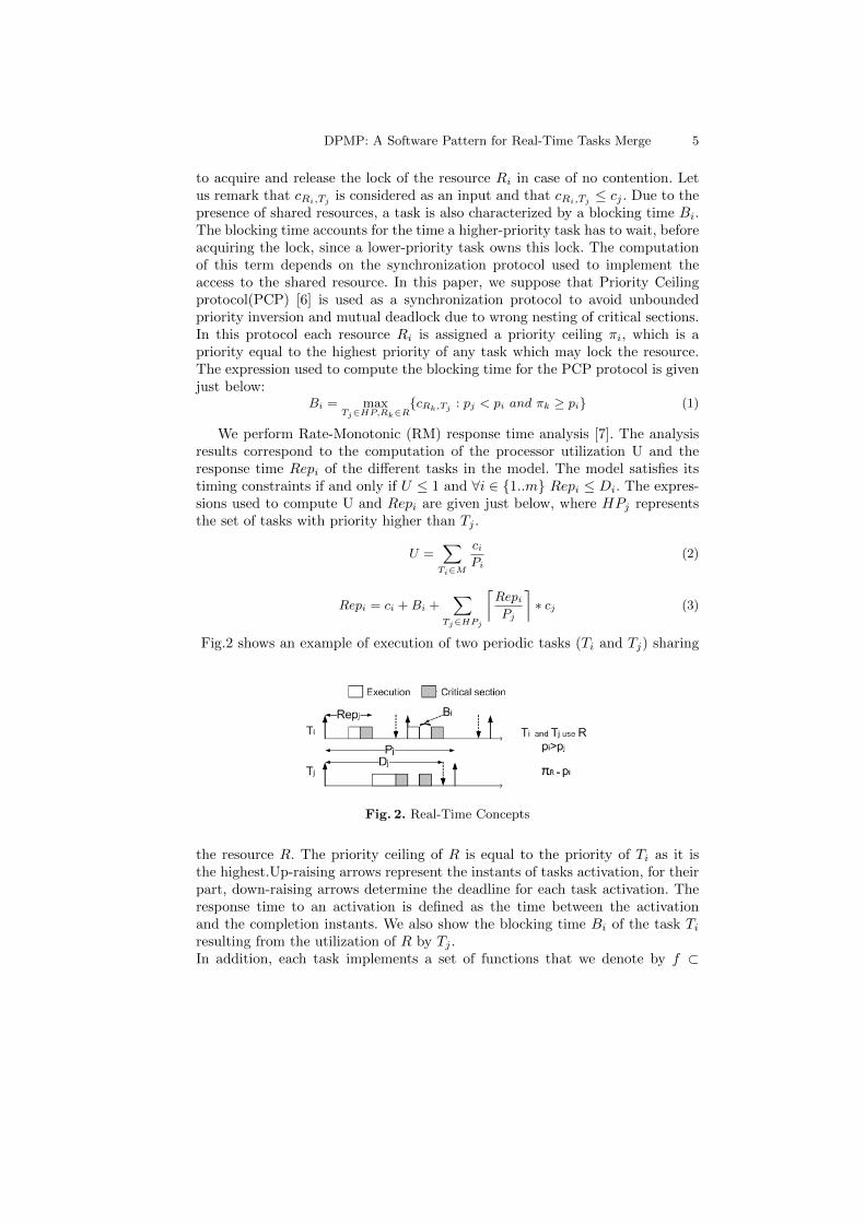
Fig.2 shows an example of execution of two periodic tasks (Ti and Tj) sharing
Fig. 2. Real-Time Concepts
the resource R. The priority ceiling of R is equal to the priority of Ti as it isthe highest.Up-raising arrows represent the instants of tasks activation, for theirpart, down-raising arrows determine the deadline for each task activation. Theresponse time to an activation is defined as the time between the activationand the completion instants. We also show the blocking time Bi of the task Tiresulting from the utilization of R by Tj .In addition, each task implements a set of functions that we denote by f ⊂
6 R. Mzid et al.
F/card(f) ≥ 1 such as F is the set of functions defined by the application (fromthe functional model).
3 Problem Statement and Solution
In this section, we identify the case where the Distinct Priority Merge Pattern(DPMP) must be applied. Then the proposed solution is detailed.
3.1 Problem Statement
This pattern is automatically applied on the design model when the DeploymentFeasibility Tests step detects that the number of distinct priority levels usedin the architectural model exceeds the number allowed by the RTOS for theconsidered application (i.e. n > N). The resulting design model after applyingthis pattern must still verifying the timing requirements as specified in section2.2.
3.2 Solution Description
In order to solve the problem (i.e. n > N), we propose to reduce n to be equalto N by merging tasks having distinct priority levels. This operation is repeateduntil the number of distinct priority levels becomes equal to N. However, theproposed solution must preserve:
1. The high level specification i.e. the activation rate of the different functionsdefined in the specification must be preserved.
2. The real-time constraints i.e. the response time of the all considered tasks islower than their deadline.
Let us consider an initial model M = {T1, T2, ., Tm} defining m tasks and ndistinct priority levels (n ≤ m). Let us consider also two tasks Ti and Tj ∈M , each task is defined by a set of parameters; Ti = (pi, Ci, Pi, Di, Bi, fi) andTj = (pj , Cj , Pj , Dj , Bj , fj) such as pi 6= pj , Pj ≥ Pi and fi, fj correspondsto the functions implemented respectively by Ti and Tj . We denote by T ′i thetask resulting from merging these two tasks such as T ′i = (p′i, C
′i, P′i , D
′i, B′i, f′i).
Consequently, the resulting model M ′ consists of m-1 tasks and n-1 distinctpriority levels.The obtained task T ′i is described in Fig.3(a).
The problem with the resulting model described in Fig.3(a) where one of thetwo merged tasks will be executed with a rate different from the one defined inthe high level specification and thus the first constraint (1) previously definedwill be violated. In order to avoid this problem, we consider also in the solutionthat only harmonic tasks may be merged (i.e. two tasks Ti and Tj are harmonicif and only if (Pj mod Pi = 0). By considering this additional assumption
(Pj
Pi= q with q in an integer), the period of the resulting task which corresponds
to minimum of the two periods will be equal to Pi and the implementation of
DPMP: A Software Pattern for Real-Time Tasks Merge 7
(a) Solution without considering harmonictasks
(b) Solution with harmonic tasks considera-tion
Fig. 3. Solution Description
f ′i will be modified in such a way that the execution rate of the two functions ispreserved. The new solution is presented in Fig. 3(b).In order to guarantee the second constraint (2), we have to re-validate the modelafter merging the tasks in order to verify whether the new design model stillsatisfy the timing constraints.
4 DPMP Formulation
This section presents an algorithmic description of the previously proposed so-lution. Then, we show the limitations of this method and we propose a MILPformulation of the DPMP pattern.
4.1 Heuristic Method
Algorithm 1 just below corresponds to an algorithmic description of the DPMPpattern. This algorithm merges recursively tasks in pairs. After each merge, thisalgorithm performs a re-validation to verify the timing properties. The algorithmends, when the number of distinct priority levels used in the resulting model isequal to the number authorized by the target RTOS or when there is no harmonictasks in the model. The complexity of this algorithm is linear and it depends onthe number of tasks in the initial model.
Heuristic Method Limitations The problem of merging tasks with the objec-tive to reduce the number of distinct applicative priority levels is a combinatorialproblem. In fact, the solution depends on the application (i.e. n and the periodof the different tasks) and the target RTOS. Consequently, the heuristic methodpresented in previous section is not always able to find the solution.Let’s consider an initial model M = {T1, T2, T3, T4}. Each task is characterizedby a set of parameters such as T1 = (1, 4, 10, 10, 0, f1), T2 = (2, 5, 20, 20, 0, f2),T3 = (3, 2, 30, 30, 0, f3) and T4 = (4, 1, 60, 60, 0, f4).The initial processor utiliza-tion is evaluated to 73,33 %. All the tasks in this model are independent andhave distinct priority levels (n=4). We can notice that task T1 is harmonic withall the other tasks and also T2, T3 are harmonic with T4. In addition, we sup-pose that the target RTOS authorizes only two priority levels for this application(N=2).
8 R. Mzid et al.
Algorithm 1: DistinctPriorityMergePatternInput:Ma: Design Model describing the applicationN : The number of distinct priority levels allowed by the RTOS for the consideredapplicationRef-Period : A reference period used to detect harmonic tasksOutput:MRes: New design model after reducing the number of priority levelsNotations:Ref-Task : The reference task with the lowest value of periodH-Tasks: The set of tasks which are harmonic with Ref-Taskn: The number of distinct priority levels used in the design modelbegin
MRes ←−Ma
n ←− getPriorityLevelsNumber(Ma)Ref-Task ←− getMinPeriod(Ma, Ref-Period)if (Ref-Task 6= null) then
for (is ∈Ma / is is a periodic task) doif (IsInteger(period(is), period(Ref-Task)) then
if (priority(is)6= priority(Ref-Task)) thenadd(is, H-Tasks)
if (SizeOf(H-Tasks) ≤ 1) thenRef-Period ←− period(Ref-Task)DistinctPriorityMergePattern(Ma,N ,Ref-Period)
elseif (n � N) then
M ′a ←− Merge(H-Tasks[1],H-Tasks[2])
OK ←− Re-Validate (M ′a)
if (Ok = true) thenMRes ←− M ′
aDistinctPriorityMergePattern(MRes,N ,Ref-Period)
return MRes
Table 1. Example: Possible Solutions and Utilization Estimation
Possible Solutions Utilization
M1 = ({T1, T2}, {T3, T4}) 100%
M2 = ({T1, T3}, {T2, T4}) 90%
M3 = ({T1, T2, T3}, T4) 111,67%
M4 = (T2, {T1, T3, T4}) 95%
M5 = (T3, {T1, T2, T4}) 106,66%
As a result, for this particular example, 5 solutions are possible. These solu-tions are presented in Table 1. For the first solution for example, we choose tomerge T1 and T2 from one side and T3 and T4 from the other side in order toobtain the model M1 consisting of just two tasks and thus two distinct prioritylevels. For this particular example, the heuristic method didn’t find a feasiblesolution as it found M3 which is not feasible due to analysis issues (utilization111,67%� 100%). Therefore, this method is not always effective. From theseconsiderations, an appropriate method must be considered to solve this prob-lem. This method must be able to confirm whether a solution for each particularproblem (application and RTOS) exists. In addition, when many solutions are
DPMP: A Software Pattern for Real-Time Tasks Merge 9
available, this method should find one which costs less performance degradation.In next section, we propose a MILP formulation of this problem.
4.2 MILP Formulation
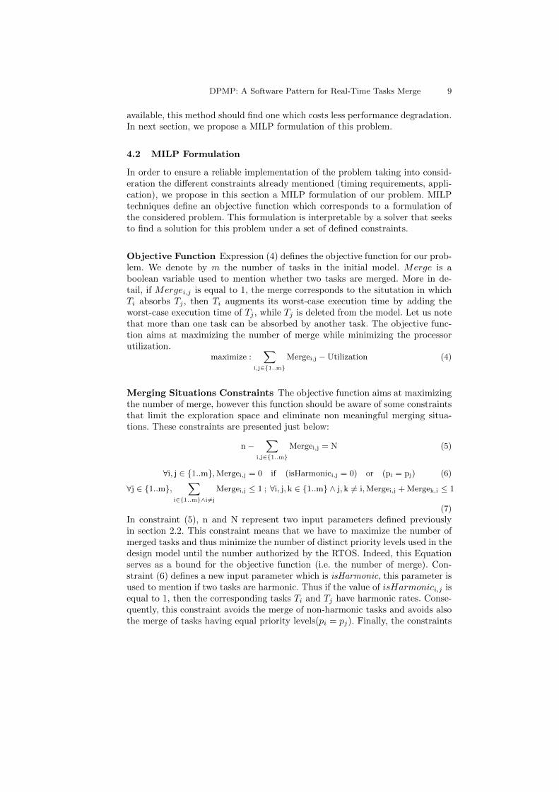
In order to ensure a reliable implementation of the problem taking into consid-eration the different constraints already mentioned (timing requirements, appli-cation), we propose in this section a MILP formulation of our problem. MILPtechniques define an objective function which corresponds to a formulation ofthe considered problem. This formulation is interpretable by a solver that seeksto find a solution for this problem under a set of defined constraints.
Objective Function Expression (4) defines the objective function for our prob-lem. We denote by m the number of tasks in the initial model. Merge is aboolean variable used to mention whether two tasks are merged. More in de-tail, if Mergei,j is equal to 1, the merge corresponds to the situtation in whichTi absorbs Tj , then Ti augments its worst-case execution time by adding theworst-case execution time of Tj , while Tj is deleted from the model. Let us notethat more than one task can be absorbed by another task. The objective func-tion aims at maximizing the number of merge while minimizing the processorutilization.
maximize :∑
i,j∈{1..m}
Mergei,j −Utilization (4)
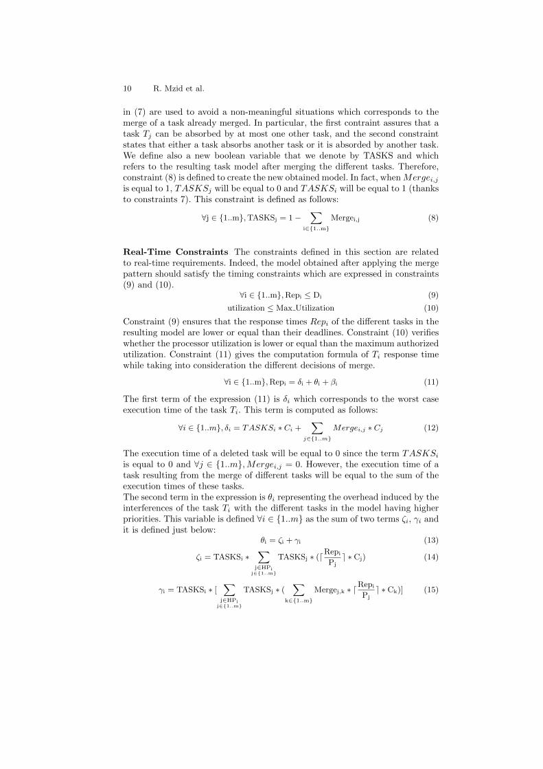
Merging Situations Constraints The objective function aims at maximizingthe number of merge, however this function should be aware of some constraintsthat limit the exploration space and eliminate non meaningful merging situa-tions. These constraints are presented just below:
n−∑
i,j∈{1..m}
Mergei,j = N (5)
∀i, j ∈ {1..m},Mergei,j = 0 if (isHarmonici,j = 0) or (pi = pj) (6)
∀j ∈ {1..m},∑
i∈{1..m}∧i 6=j
Mergei,j ≤ 1 ; ∀i, j, k ∈ {1..m} ∧ j, k 6= i,Mergei,j + Mergek,i ≤ 1
(7)
In constraint (5), n and N represent two input parameters defined previouslyin section 2.2. This constraint means that we have to maximize the number ofmerged tasks and thus minimize the number of distinct priority levels used in thedesign model until the number authorized by the RTOS. Indeed, this Equationserves as a bound for the objective function (i.e. the number of merge). Con-straint (6) defines a new input parameter which is isHarmonic, this parameter isused to mention if two tasks are harmonic. Thus if the value of isHarmonici,j isequal to 1, then the corresponding tasks Ti and Tj have harmonic rates. Conse-quently, this constraint avoids the merge of non-harmonic tasks and avoids alsothe merge of tasks having equal priority levels(pi = pj). Finally, the constraints
10 R. Mzid et al.
in (7) are used to avoid a non-meaningful situations which corresponds to themerge of a task already merged. In particular, the first contraint assures that atask Tj can be absorbed by at most one other task, and the second constraintstates that either a task absorbs another task or it is absorded by another task.We define also a new boolean variable that we denote by TASKS and whichrefers to the resulting task model after merging the different tasks. Therefore,constraint (8) is defined to create the new obtained model. In fact, whenMergei,jis equal to 1, TASKSj will be equal to 0 and TASKSi will be equal to 1 (thanksto constraints 7). This constraint is defined as follows:
∀j ∈ {1..m},TASKSj = 1−∑
i∈{1..m}
Mergei,j (8)
Real-Time Constraints The constraints defined in this section are relatedto real-time requirements. Indeed, the model obtained after applying the mergepattern should satisfy the timing constraints which are expressed in constraints(9) and (10).
∀i ∈ {1..m},Repi ≤ Di (9)
utilization ≤ Max Utilization (10)
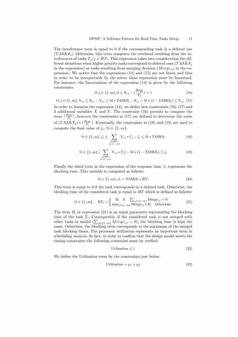
Constraint (9) ensures that the response times Repi of the different tasks in theresulting model are lower or equal than their deadlines. Constraint (10) verifieswhether the processor utilization is lower or equal than the maximum authorizedutilization. Constraint (11) gives the computation formula of Ti response timewhile taking into consideration the different decisions of merge.
∀i ∈ {1..m},Repi = δi + θi + βi (11)
The first term of the expression (11) is δi which corresponds to the worst caseexecution time of the task Ti. This term is computed as follows:
∀i ∈ {1..m}, δi = TASKSi ∗ Ci +∑
j∈{1..m}
Mergei,j ∗ Cj (12)
The execution time of a deleted task will be equal to 0 since the term TASKSi
is equal to 0 and ∀j ∈ {1..m},Mergei,j = 0. However, the execution time of atask resulting from the merge of different tasks will be equal to the sum of theexecution times of these tasks.The second term in the expression is θi representing the overhead induced by theinterferences of the task Ti with the different tasks in the model having higherpriorities. This variable is defined ∀i ∈ {1..m} as the sum of two terms ζi, γi andit is defined just below:
θi = ζi + γi (13)
ζi = TASKSi ∗∑
j∈HPij∈{1..m}
TASKSj ∗ (dRepi
Pje ∗ Cj) (14)
γi = TASKSi ∗ [∑
j∈HPij∈{1..m}
TASKSj ∗ (∑
k∈{1..m}
Mergej,k ∗ dRepi
Pje ∗ Ck)] (15)
DPMP: A Software Pattern for Real-Time Tasks Merge 11
The interference term is equal to 0 if the corresponding task is a deleted one(TASKSi). Otherwise, this term computes the overhead resulting from the in-terferences of tasks Tj/j ∈ HPi. This expression takes into consideration the dif-ferent situations when higher priority tasks correspond to deleted ones (TASKSj
in the expression) or tasks resulting from merging decision (Mergej,k in the ex-pression). We notice that the expressions (14) and (15) are not linear and thusin order to be interpretable by the solver these expression must be linearized.For instance, the linearization of the expression (14) is given by the followingconstraints:
In order to linearize the expression (14), we define new constraints (16) (17) and2 additional variables X and Y . The constraint (16) permits to compute theterm dRepi
Pje, however the constraints in (17) are defined to determine the value
of (TASKSj) ∗ dRepi
Pje. Eventually, the constraints in (18) and (19) are used to
compute the final value of ζi, ∀i ∈ {1..m}.
∀i ∈ {1..m}, ζi ≤∑
j∈HPij∈{1..m}
Yi,j ∗ Cj ; ζi ≤ M ∗ TASKSi (18)
∀i ∈ {1..m}, [∑
j∈HPij∈{1..m}
Yi,j ∗ Cj]−M ∗ (1− TASKSi) ≤ ζi (19)
Finally the third term in the expression of the response time βi represents theblocking time. This variable is computed as follows:
∀i ∈ {1..m}, βi = TASKSi ∗ BTi (20)
This term is equal to 0 if the task corresponds to a deleted task. Otherwise, theblocking time of the considered task is equal to BT which is defined as follows:
∀i ∈ {1..m}, BTi =
{Bi if
∑i,j∈{1..m} Mergei,j = 0
maxj∈{1..m} Mergei,j ∗ Bi Otherwise(21)
The term Bi in expression (21) is an input parameter representing the blockingtime of the task Ti. Consequently, if the considered task is not merged withother tasks in model (
∑j∈{1..m}Mergei,j = 0), the blocking time is kept the
same. Otherwise, the blocking term corresponds to the maximum of the mergedtask blocking times. The processor utilization represents an important term inscheduling analysis. In fact, in order to confirm that the design model meets thetiming constraints the following constraint must be verified:
Utilization ≤ 1 (22)
We define the Utilization term by the constraints just below:
Utilization = µ1 + µ2 (23)
12 R. Mzid et al.
µ1 =∑
i∈{1..m}
TASKSi ∗ (Ci
Pi) ; µ2 =
∑i∈{1..m}
TASKSi ∗∑
j∈{1..m}
Mergei,j ∗ (Cj
Pi) (24)
Under these constraints, the objective function will seek for the best way tomerge tasks (i.e. the optimized solution in terms of utilization) in order to re-duce the number of used priority levels while ensuring the respect of timingproperties.Let’s consider the same example previously introduced in section 4.1. Consider-ing this problem, our linear program confirms that a solution exists and generatesthe following Merge matrix:
Merge =
0 0 1 00 0 0 10 0 0 00 0 0 0
This matrix shows that the solution considered by the solver is the merge of T1and T3 and the merge of T2 and T4. The processor utilization of the resultingmodel is 90%. Now if we compare this solution with the different possible solu-tions given in Table 1, we can conclude that the latter corresponds to M2 whichis the best one in terms of processor utilization.The solution generated by the linear program will be interpreted by our frame-work in order to provide the information to the designer on how the design modelmust be re-factored.
5 Experimental Results
In this section, we present a set of experiments to test the effectiveness of theproposed pattern in terms of applicability and scalability. The experiments arecarried-out on Intel Core i5-3360M processor running at 2.8 GHz with 4GB ofcache memory. CPLEX is used as a MILP solver for the whole set of experi-ments.We define also a new parameter that we denote Cost. This parameter referencesthe performance loss and is defined as the difference between the utilization eval-uated on the initial model and the utilization evaluated on the model resultingfrom the application of the merge pattern in order to avoid non-implementabledesign models. Expression 25 given just below defines this parameter:
We define the extensibility as the capacity to integrate additional applications(or functions) on the same platform. In this section, we suppose that the firstfocus of the designer is to maximize extensibility at the implementation level
DPMP: A Software Pattern for Real-Time Tasks Merge 13
even at the expense of some performance loss. For that achievement, the de-signer should determine the processor utilization authorised for his applicationthat we denote by Max-Utilization and the number of distinct priority levelsdenoted by N. This task is not trivial because it strongly depends on the ap-plication. The previously described linear program provides a sort of guidancefor the designer to help him determining one of these parameters by fixing thesecond. Therefore, two scenarios are considered: (1) the designer defines the max-imum number of priority levels (N) that he wants to reserve for his applicationand asks the linear program to determine the minimum processor utilizationnecessary for this achievement.(2) the designer defines the maximum processorutilization (Max-Utilization) authorized for his application and asks the linearprogram to determine the minimum number of priority levels that are necessaryto achieve such utilization. For scheduling issues, we suppose that the consideredapplication is the first to be implemented on the platform and that the reservedpriority levels are the higher ones.In order to illustrate this idea, we consider an example of an architectural modeldescribing an application; this model is given in table 2. The design model con-sists of 6 tasks; each task is characterized by a set of parameters. Besides, themodel defines also two shared resources R1 and R2; the resource R1 is sharedbetween the two tasks T1 and T3, however R2 is shared between T2 and T5.After, the different design choices, the designer performs validation to verify thetiming constraints. Validation results are also presented in table 2; all the tasksmeet their deadlines since their response times are lower than their deadlines.The processor utilization for this model is evaluated to 39, 69%.
Table 2. Example of an Architectural Model
Task Period Deadline Wcet Priority Blocking Time Response Time
T1 10 10 2 0 2 4
T2 20 20 2 1 2 6
T3 40 40 2 2 1 7
T4 80 80 3 3 1 10
T5 160 160 1 4 0 10
T6 320 320 1 5 0 13
Now let’s consider the first scenario. For extensibility issues the designer wantsto reserve just 3 priority levels for this application at the implementation level.To this end, he fixes the number N to 3 and asks the pattern to determineminimum processor utilization that should be reserved in that case. Then, thepattern generates the corresponding value which is equal to 46, 25%. For thesecond scenario, if the designer fixes the Max-Utilization to 45%, the patterndetermines that the minimum number of priority levels that should be reservedfor such utilization is 4 (N=4). Fig.4 illustrates the variation of the Cost withregard to the extensibility for the considered application.We have already mentioned that the extensibility is inversely proportional to
14 R. Mzid et al.
Fig. 4. Cost Variation Versus Extensibility
the number of priority levels reserved at the implementation level. Hence, in thegraph we evaluate the extensibility to be equal to 1
N . We can conclude that theperformance loss increases when the extensibility increases.
Insufficient Priority Levels for Large Scale Applications
In this section, we are interested on the evaluation of the merge pattern on largescale systems. In that case, during the deployment phase, the problem of insuf-ficient number of priority levels authorized by the target RTOS will more likelyoccur. To this end, we consider different design models. Each model M consistsof {T1, T2, , Tn} ; n defines the number of distinct priority levels used in themodel. We suppose also that each task Ti ∈M is defined by a set of parameters(pi, Ci, Pi, Di, Bi). In addition, we assume that for each model ∀i, j ∈ {1..n}, Tiand Tj are harmonic (i.e. Pj mod Pi =0) and ∀i, j ∈ {1..n} pi 6= pj . This bringsus to identify different categories of RTOS depending on their number of distinctpriority levels. In this paper, we consider two examples of RTOSs; MicroC/OS-II [8] and Ecos [9]. Indeed, MicroC/OS-II offers 56 applicative distinct prioritylevels, however, Ecos provides the possibility to configure the number of dis-tinct priority levels from 1 to 32 (we consider two cases where N=16 and N=8).For each considered model, we evaluate the deployment cost when a particularRTOS is targeted. Fig.4 (a) shows the variation of the cost (in %) for the alreadymentioned RTOSs in function of the application (by increasing the priority levelsnumber).This evaluation shows that, in some cases, the deployment of a real time ap-plication requires some performance degradation, due the implementation con-straints, to generate valid implementation models. This deployment cost is stronglyinfluenced by the application and the target operating system. The merge pat-tern that we have proposed offers to the designer the possibility to estimate theperformance loss for a particular application and a RTOS and thus provides asource of guidance for the selection of the appropriate operating system.Fig.4 (b) illustrates the variation of the resolution time in seconds. In fact, in thisgraph we evaluate the execution time of the linear program using CPLEX fordifferent applications and for the Ecos Operating system configured respectivelywith 8 and 16 authorized applicative priority levels. From these graphics (Fig.4
DPMP: A Software Pattern for Real-Time Tasks Merge 15
(a) Cost Evaluation For MicroC-OS/II and Ecos
(b) Evaluation of the ResolutionTime in Seconds
Fig. 5. Evaluation of The Merge Pattern for Large Scale Applications
(b)) we can conclude that the time required by the linear program to make deci-sion is bounded even for large scale applications. The second conclusion is thatthis time depends strongly on the application and the target RTOS. In fact, itincreases when the number of distinct priority levels in the architectural modelincreases and the number of priority levels authorized by the RTOS decreases.
6 Related Work
Several approaches have been proposed to provide guidelines for the software de-velopment of RTES in a MDD context. In [10], the authors propose a generativeprocess to transform an application deployed on one RTOS to another based onan explicit description of the involved RTOSs using SRM. This approach focusesespecially on the portability requirement by proposing generic transformationsenabling the deployment of the same application on several RTOSs. This workfocuses on the structural aspect but makes the assumption that the deploymentis always possible without any consideration of the potential difference betweenthe semantics of RTOSs resources. The authors in [11] extend the previous workby introducing behavioural information in platforms description. This approachfocuses on the separation of concerns and portability while ensuring an auto-matic full code generation. To achieve that, the authors introduce behaviouralpatterns in platform models for a detailed description of the different servicesoffered by the target platform. Indeed, these previously mentioned works do notconsider real-time validation.
In order to address real-time concerns, several works focus a specific standardand do not address the portability issue. In [13], the author extends the RT-UMLprofile to support the creation and validation of OSEK-compliant models. In[14], the authors use an OSEK-compliant abstract platform called SmartOSEK[15] and define a set of transformation rules to create OSEK-compliant modelsfrom UML models. In addition, this approach enables the simulation of the re-sulting OSEK-compliant models and provides the designer with the results tooptimize this model at design level. In [16], the authors use RT-UML to an-notate UML models describing real-time applications with timing properties.Then they identify the mapping rules between the resulting model and RT-Java
16 R. Mzid et al.
as a target platform. The objective of this work is to properly propagate thereal-time constraints into the RT-java specific model in order to validate them.From the other side, many existing works define MDD approaches to guide thedesign choices and generate architectural models satisfying timing properties.In [12] authors provides an approach to automatically generate the architec-tural model from the functional blocks. The focus of this work is to automatethis generation and ensure optimized architectural models in terms of timingproperties. In [1] authors propose a MARTE-based methodology by introducinganalysis from the functional level to guide the generation of a valid design modelin terms of timing requirements. These works still keeping portability by ensur-ing platform-independent architectural models. However they in general end atthe design level and do not focus on deployment issues. Hence, our approachaims at extending the latter methodology [1] by focusing on the refinement to-ward implementation of the resulting design model. This work is a step towardproviding portability and separation of concerns from one side and early verifi-cation of timing properties from the other side during the deployment processof a real-time application on a several RTOSs.
7 Conclusion and Perspectives
In this paper we have proposed a model-driven approach to guide the transitionfrom the design to the implementation model during the development of real-time applications. We have especially addressed the problem where the numberof distinct priority levels used to validate the design model exceeds the numberauthorized by the RTOS. In that case, we have proposed a software patternthat we have called Distinct Priority Merge Pattern(DPMP) that automaticallyperform the re-factoring of the architectural model with the objective of solvingthe problem. The application of this pattern preserves the high level specificationand the timing requirements while reducing the number of used distinct prioritylevels. Due to the complexity of this treatment, a MILP formulation of thispattern have been proposed. This formulation permits to confirm whether asolution exists for the problem and finds the better one in terms of processorutilization.
As perspective of this work, we aim at considering other problems such astimer granularity, equal priority levels, etc and proposing for each particularproblem a software pattern to enrich our pattern base. In addition, we can extendthis work by considering the behavioural aspect and thus other problems mustbe considered and consequently additional software pattern must be defined.
References
1. C. Mraidha, S. Tucci-Piergiovanni, S. Gerard. Optimum: A MARTE-based method-ology for Schedulability Analysis at Early Design Stages. In proceeding of the ThirdIEEE international workshop UML and Formal Methods (UML&FM 2010). Shang-hai, China
DPMP: A Software Pattern for Real-Time Tasks Merge 17
2. F. Singhoff, J. Legrand, L. Nana, and L. Marc. Cheddar: a Flexible Real TimeScheduling Framework. International ACM SIGADA Conference, Atlanta, Novem-ber 2004.
3. R. Mzid, Ch. Mraidha, J-P. Babau, M. Abid. A MDD Approach for RTOS In-tegration on Valid Real-Time Design Model. The 38th Euromicro Conference Onsoftware Engineering and Advanced Applications (SEAA12), Cesme, Izmir, Turkey,September 2012.
4. R. Mzid, Ch. Mraidha, J-P. Babau, M. Abid. Real-Time Design Models to RTOS-Specific Models Refinement Verification. The 5th International Workshop on ModelBased Architecting and construction of Embedded Systems ACES-MB 2012 in Con-junction with the 15th International Conference on Model Driven Engineering Lan-guages & Systems MODELS 2012, Innsbruck, Austria, September 2012.
5. Object Management Group, UML Profile for MARTE: Modeling and Analysis ofReal-Time Embedded Systems, Object Management Group, Inc., September 2010,OMG document number: ptc/2010-08-32
6. J. B. Goodenough and L. Sha. The priority ceiling protocol: A method for minimiz-ing the blocking of high priority Ada tasks, volume 8.ACM, 1988
7. M. H. Klein, T. Ralya, B. Pollak, R. Obenza, and M. G. Harbour.A practitionershandbook for real-time analysis. Kluwer Academic Publishers, 1993.
8. Jean J. Labrosse. MicroC/OS-II The Real-Time Kernel9. Anthony. J. MASSA Embedded Software Development with Ecos10. F. Thomas, J. Delatour, F. Terrier, and S. Gerad. Toward a framework for ex-
plicit platform-based transformations. In Proceeding of the 11th IEEE Symposiumon Object Oriented Real-Time Distributed Computing (ISORC). Orlondo, Florida,USA, May 2008.
11. W. E. H. Chehade, A. Radermacher, F. Terrier, B. Selic, and S. Gerard, A model-driven framework for the development of portable real-time embedded systems, inProceedings of the 16th IEEE International Conference on Engineering of ComplexComputer Systems. Las Vegas, Nevada, USA: IEEE Computer Society, 2011, pp.4554.
12. C. Bartolini, G. Lipari, and M. D. Natale, From functional blocks to the synthesisof the architectural model in embedded real-time applications, in Proc. IEEE RealTime and Embedded Technology and Applications Symposium (RTAS), 2005, pp.458467.
13. A. Moore. Extending the RT-prole le to support the OSEK infrastructure. In Pro-ceedings of the 5th IEEE International Symposium on Object-Oriented Real-TimeDistributed Computing, pages 341347, Washington, DC, Apr. 2002.
14. G. Yang, M. Zhao, L. Wang, and Z. Wu, ”Model-based Design and Verificationof Automotive Electronics Compliant with OSEK/VDX,” presented at The SecendInternational Conference on Embedded Software and System (ICESS), Xi’an, 2005.
15. M. Zhao, Z. Wu, G. Yang, L. Wang, and W. Chen,”SmartOSEK: A DependablePlatform for Automobile Electronics,” The First International Conference on Em-bedded Software and System, vol. Springer-Verlag GmbH ISSN: 0302-9743, pp. 437,2004.
16. Becker, L.B.; Holtz, R.; Pereira, C.E. On Mapping RTUML Specifications to RT-Java API: Bridging the Gap. In: 5th IEEE International Symposium on Object-Oriented Real-Time Distributed Computing, Washington, USA, 2002. p. 348-355