AmericasUSA: Delta Electronics (Americas) Ltd.5101 Davis Drive, Research Triangle Park, NC 27709, U.S.A.TEL: +1-919-767-3813 / FAX: +1-919-767-3969
Brazil: Delta Electronics Brazil Rua Itapeva, 26 - 3°, andar Edificio Itapeva, One - Bela Vista 01332-000 - São Paulo - SP - Brazil TEL: +55-12-3932-2300 / FAX: +55-12-3932-237
Mexico: Delta Electronics International Mexico S.A. de C.V.Gustavo Baz No. 309 Edificio E PB 103Colonia La Loma, CP 54060Tlalnepantla, Estado de MéxicoTEL: +52-55-3603-9200
1 s t The f i r s t ve rs ion was pub l ished. 2018/12/12
2 n d The second vers ion was pub l ished. 2020/4 /30
3 r d
1 .Chapter 1 : A l l images concern ing DPMSoft i n ter face are changed.
2 .Chapter 2 : A l l images concern ing commun icat ion se t t ing are changed.
3 .Add sec t ion 3 .16: Phasor D iagram. 4 .Add sec t ion 3 .17: Las t Month TOU. 5 .Add sec t ion 3 .18: Time o f Use Max Demand. 6 .Chapter 4 .1 : Add con tent concern ing Ethernet , Pu lse
Output , Defau l t Page D isp lay in the Meter, and Energy Un i t D isp lay in the Mete r.
7 .Chapter 4 .2 : Change images and add content concern ing CO 2 Emiss ion, Data Word Order, Password Modi f i ca t ion , A larm, and TOU.
8 . Add sec t ion 4 .4 : Data Log-DA5X0.
2020/11/20
4 t h
1 .Add descr ip t ion concern ing webpage opera t ions fo r mu l t i - l oop mode ls as we l l as se t t ings to co l lapse and expand the opera te area a t the beg inn ing o f chapter3 .
2 .Update exp lanatory p ic tures in chapte r 3 .1 to 3 .18. 3 .Add sec t ion 3 .14 : A larm His to ry. 4 .Update head ing number ings in chapte r 4 . 5 .Add content concern ing mu l t i - l oop func t ion to sec t ion
4 .1 .2 Trans former Rat io . 6 .Add sec t ion 4 .1 .3 : Cur rent Trans former. 7 .Add sec t ion 4 .1 .5 : Power Sys tem. 8 .Add exp lanat ion and update p ic tu res re la t ing to Re lay
Output in sec t ion 4 .1 .6 A larm. 9 .Update sec t ion 4 .1 .7 : Communicat ions 10.Update sec t ion 4 .1 .9 : Demand. 11.Update sec t ion 4 .1 .11: BACnet Dev ice ID. 12.Add descr ip t ions concern ing re lay outputs to sec t ion
4 .1 .13 DIDO Set t ing . 13 .Add content concern ing mu l t i - l oop func t ion to sec t ion
4 .1 .15 Pu lse Output . 14 .Add exp lanat ion and update p ic tu res in sec t ion 4 .1 .17
Disp lay Un i t Format in the Meter. 15 .Add exp lanat ion and update p ic tu res in sec t ion 4 .1 .18
Disp lay Un i t Format . 16 .Add sec t ion 4 .1 .19: Value Low Cut . 17 .Add sec t ion 4 .1 .20: Loop Quant i t y. 18 .Add sec t ion 4 .1 .21 : Back L ight Time in the Meter. 19 .Add sec t ion 4 .1 .22: Cus tom Page Disp lay in the Meter. 20 .Add sec t ion 4 .1 .23: Data Word Order. 21 .Update sec t ion 4 .2 .3 Disp lay o f Numer ica l Va lues in the
Meter. 22 .Add exp lanat ion and update p ic tu res in sec t ion 4 .2 .4
Disp lay Un i t Format .
2021/7 /26
Version Revis ion Date 23 .Add sec t ion 4 .2 .14: Cus tom Page in the Meter
(Summary-P) 24.Add sec t ion 4 .2 .15: Summary D isp lay Order in the Meter. 25 .Add sec t ion 4 .2 .16: D ig i ta l I nput . 26 .Add sec t ion 4 .2 .17: Relay Output Set t ing . 27 .Add sec t ion 4 .2 .18: Back L ight Time in the Meter. 28 .Add sec t ion 4 .2 .19: Reset Loop Parameter. 29 .Add exp lanato ry p ic tures in chapter 4 .3 Data Log. 30.Change the t i t l e o f chap ter 4 .4 to Data Log-DA
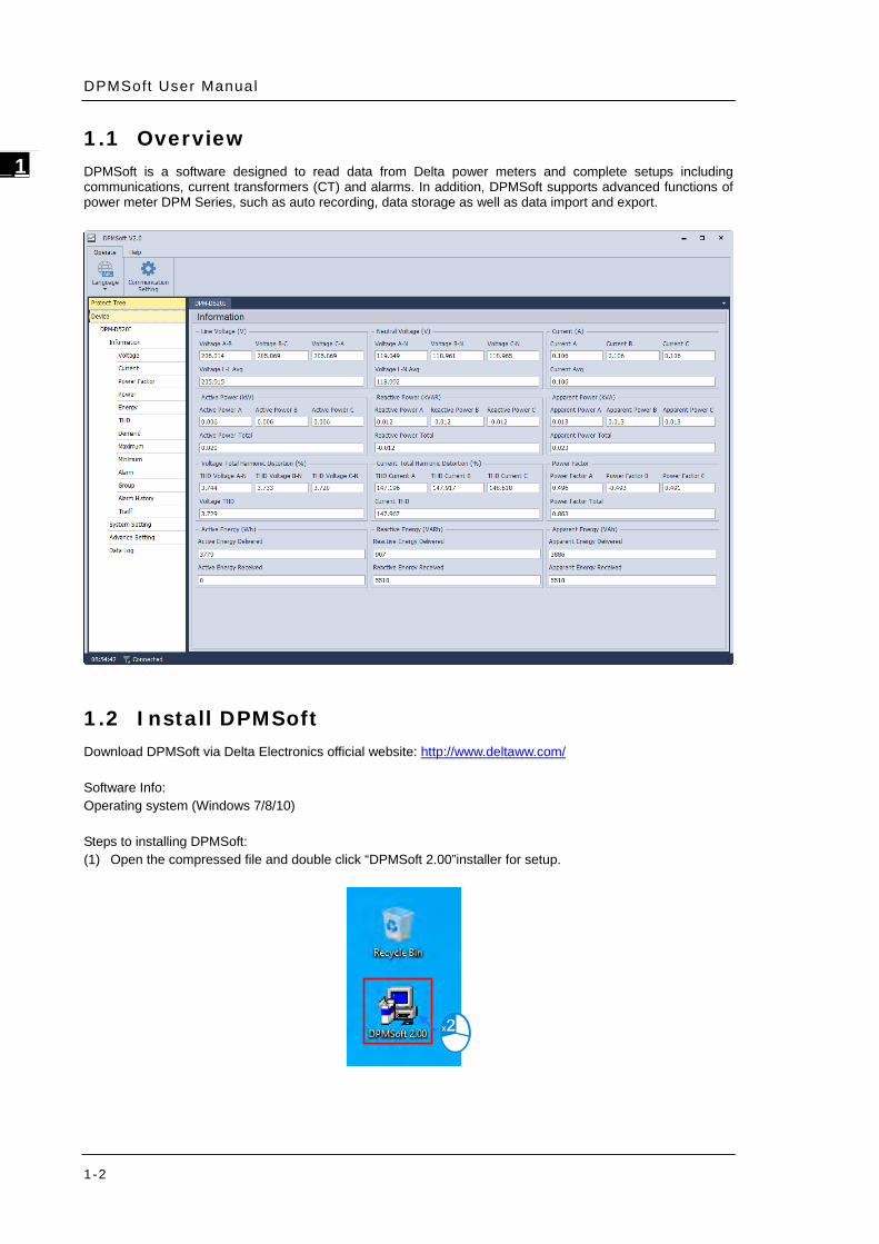
_1 1.1 Overview DPMSoft is a software designed to read data from Delta power meters and complete setups including communications, current transformers (CT) and alarms. In addition, DPMSoft supports advanced functions of power meter DPM Series, such as auto recording, data storage as well as data import and export.
1.2 Install DPMSoft Download DPMSoft via Delta Electronics official website: http://www.deltaww.com/ Software Info: Operating system (Windows 7/8/10) Steps to installing DPMSoft: (1) Open the compressed file and double click “DPMSoft 2.00”installer for setup.
Double click the installed DPMSoft icon and a pop-up window for connection will appear. There are two
methods for connecting the DPMSoft to the power meter; one is serial port communication (see bottom left) and
the other is TCP/IP network connections (see bottom right).
2.1 Serial Port Communication Settings
Steps to set up serial port communication:
(1) Select a COM Port.
Chapter 2 DPMSoft Connect ions
2-3
2_
(2) Input the slave station, communication mode, Baud rate, data bit, parity, stop bit of the power meter.
Enter the required timeout (ms) and the command speed for DPMSoft.
Communication Mode: RTU/ ASCII
Baud Rate: 9600/ 19200/ 38400
Parity: NONE/ EVEN/ ODD
Data Bit: 7/ 8
Stop Bit: 1/ 2
(3) After the setup, connect to the power meter by clicking “Connect”. For successful connection, the
DPMSoft main page window will pop-up; for unsuccessful connection, a pop-up window will appear
to point out the connection failure.
DPMSoft User Manual
2-4
_2
2.2 TCP/IP Network Connections
Steps to set up TCP/IP Network Connections:
(1) Setup the IP address and station of the power meter. When the RS-485 is used to communicate
between the power meter and Ethernet converter, enter the IP address, station of the router and the
required timeout (ms) based on your needs
(2) When setup is completed, connect to the power meter by clicking “Connect”. For successful
connection, the DPMSoft main page window will pop-up; for unsuccessful connection, a pop-up
window will appear to issue the connection failure.
Chapter 2 DPMSoft Connect ions
2-5
2_
The DPMSoft main page window (see below) pops-up when connection is successful.
DPMSoft User Manual
2-6
_2
MEMO
3-1
3 Chapter 3 DPMSoft Screen Display
Table of Contents
3.1 Information .......................................................................................... 3-3 3.2 Voltage ................................................................................................ 3-4 3.3 Current ................................................................................................ 3-4 3.4 Power Factor ......................................................................................... 3-5 3.5 Power .................................................................................................. 3-5 3.6 Energy ................................................................................................. 3-6 3.7 Total Harmonic Distortion (THD) .............................................................. 3-6 3.8 Harmonic ............................................................................................. 3-7 3.9 Demand ............................................................................................... 3-7 3.10 Maximum ............................................................................................. 3-8 3.11 Minimum .............................................................................................. 3-8 3.12 Alarm .................................................................................................. 3-9 3.13 Group ................................................................................................... 3-9 3.14 Alarm History ..................................................................................... 3-14 3.15 Tariff ................................................................................................. 3-16 3.16 Phasor Diagram .................................................................................. 3-16 3.17 Last Month TOU .................................................................................. 3-17 3.18 Time of Use Max Demand ..................................................................... 3-17
DPMSoft User Manual
3-2
_3
Click to close the operate area and click again to expand as shown in follows. The position and
size of the window as well as settings in the operate area would be remembered across software
restarts.
When DPMSoft and the Delta power meter is successfully connected, the software interface displays the
language such as English, Traditional Chinese or Simplified Chinese base on the Windows system. To change
the displayed language, select the Language menu on the upper right corner of the page and choose the
desired language.
The DPMSoft screen displays including Information, Voltage, Current, Power Factor, Power, Energy, Total
Harmonic Distortion (THD), Demand, Maximum, Minimum, Alarm, Group, Alarm History and Tariff with
explanations in the following sections.
Chapter 3 DPMSoft Screen Display
3-3
3_
For multi-loop type models, you can switch the information page of the target loop with the tabs shown in the
following figure.
3.1 Information
The page displays most commonly used parameters for measurements including voltage, neutral voltage,
current, active power, reactive power, apparent power, active energy, power factor as well as voltage and
current total harmonic distortions.
DPMSoft User Manual
3-4
_3
3.2 Voltage
The page displays the average voltage and voltage per phase, voltage unbalance rate as well as the average,
phase to phase and unbalance rate value of line voltage.
Click “Voltage” in the project tree on the left side to enter the page (see below).
3.3 Current
The page displays current, current unbalance rate value.
Click “Current” in the project tree on the left side to enter the page (see below).
Chapter 3 DPMSoft Screen Display
3-5
3_
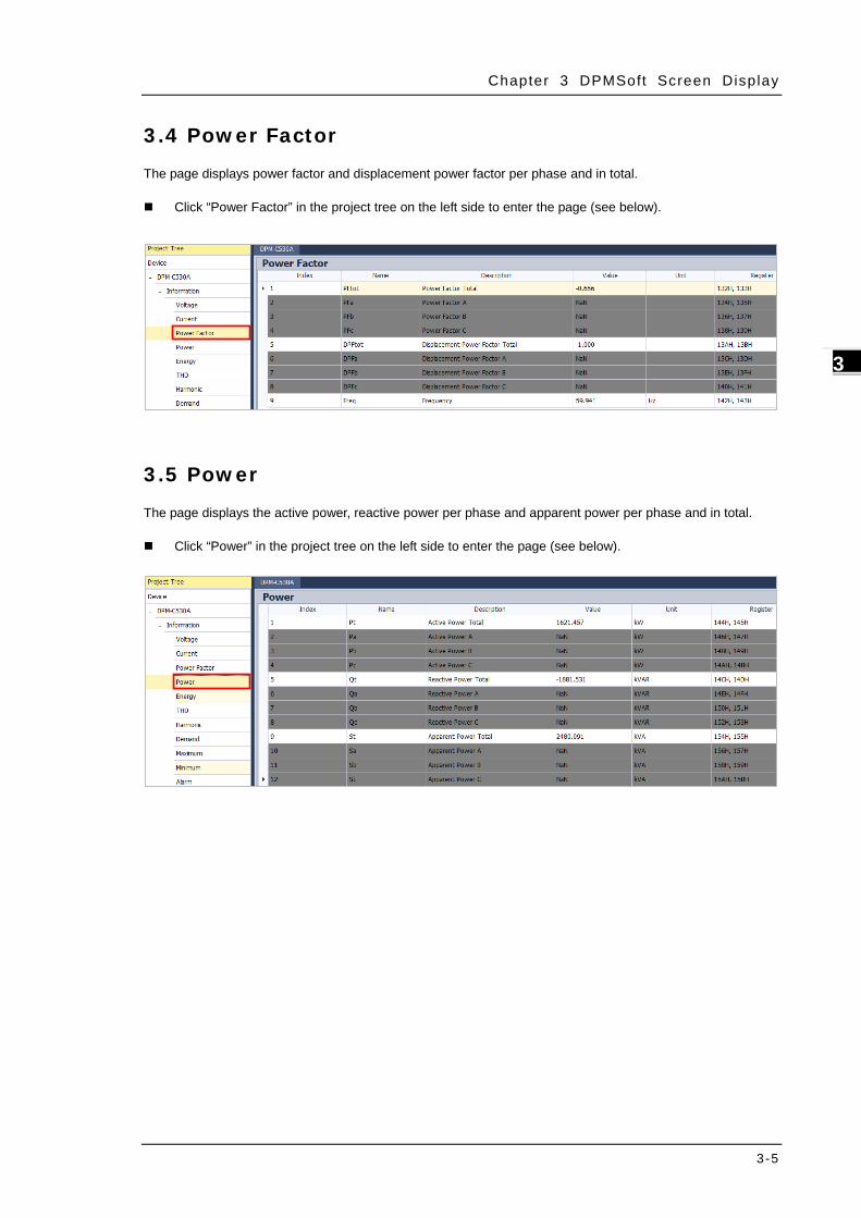
3.4 Power Factor
The page displays power factor and displacement power factor per phase and in total.
Click “Power Factor” in the project tree on the left side to enter the page (see below).
3.5 Power
The page displays the active power, reactive power per phase and apparent power per phase and in total.
Click “Power” in the project tree on the left side to enter the page (see below).
DPMSoft User Manual
3-6
_3
3.6 Energy
The page displays active, reactive and apparent energy delivered or received, automated energy recording as well as fundamental wave active power.
Click “Energy” in the project tree on the left side to enter the page (see below).
3.7 Total Harmonic Distortion (THD)
The page displays voltage THD and current THD in total as well as in per phase.
Click “THD” in the project tree on the left side to enter the page (see below).
Chapter 3 DPMSoft Screen Display
3-7
3_
3.8 Harmonic
The page displays voltage and current harmonic distortion of each phase from 1st to 31st.
Click “Harmonic” in the project tree on the left side to enter the page (see below).
3.9 Demand
The page displays the present, last and next demand value. The list also shows the peak value and its
occurring date and time.
Click “Demand” in the project tree on the left side to enter the page (see below).
DPMSoft User Manual
3-8
_3
3.10 Maximum
The page displays the maximum values, date and time of parameters.
Click “Maximum” in the project tree on the left side to enter the page (see below).
3.11 Minimum
The page displays the minimum values, date and time of parameters.
Click “Minimum” in the project tree on the left side to enter the page (see below).
Chapter 3 DPMSoft Screen Display
3-9
3_
3.12 Alarm
The page displays the current alarm status, the number of alarm events as well as time and date. If the alarm is
deactivated, the page background color is green; however, if the alarm is activated, the background color turns
red.
Click “Alarm” in the project tree on the left side to enter the page (see below).
3.13 Group
The page displays the mapping value regarding the group parameter setting.
Click “Group” in the project tree on the left side to enter the page (see below).
DPMSoft User Manual
3-10
_3
The Group page contains three useful buttons including “Group Set”, “Import” and “Export” with the following
explanations.
Group Set: The button displays the parameter data for setup through the following steps:
(1) First, select the parameters displayed on the page.
(2) Click “Group Set” to start the process after selecting the parameters.
Chapter 3 DPMSoft Screen Display
3-11
3_
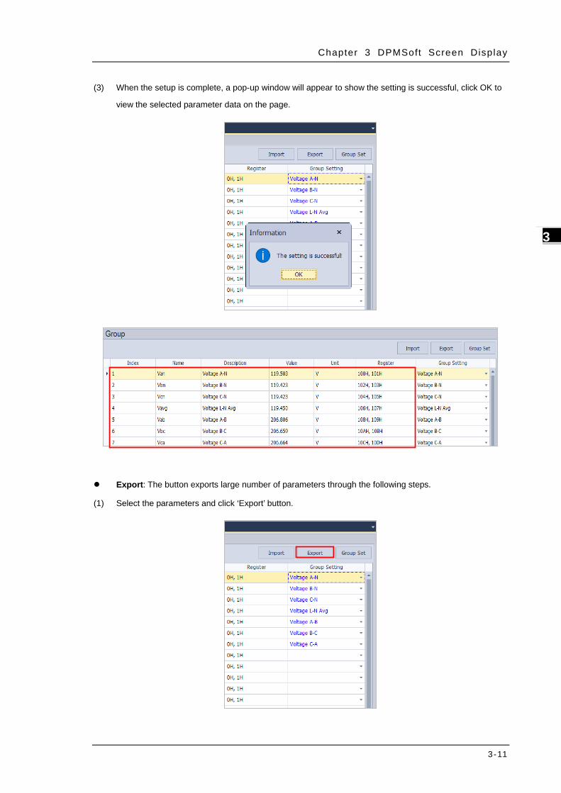
(3) When the setup is complete, a pop-up window will appear to show the setting is successful, click OK to
view the selected parameter data on the page.
Export: The button exports large number of parameters through the following steps.
(1) Select the parameters and click ‘Export’ button.
DPMSoft User Manual
3-12
_3
(2) After clicking the ‘Export’ button, a pop-up window for file saving appears. Users need to choose the
appropriate directory and click ‘Save’ to start the process.
(3) A pop-up window appears when the group data export is a success. Click OK and the export file can be
viewed from the desktop.
Chapter 3 DPMSoft Screen Display
3-13
3_
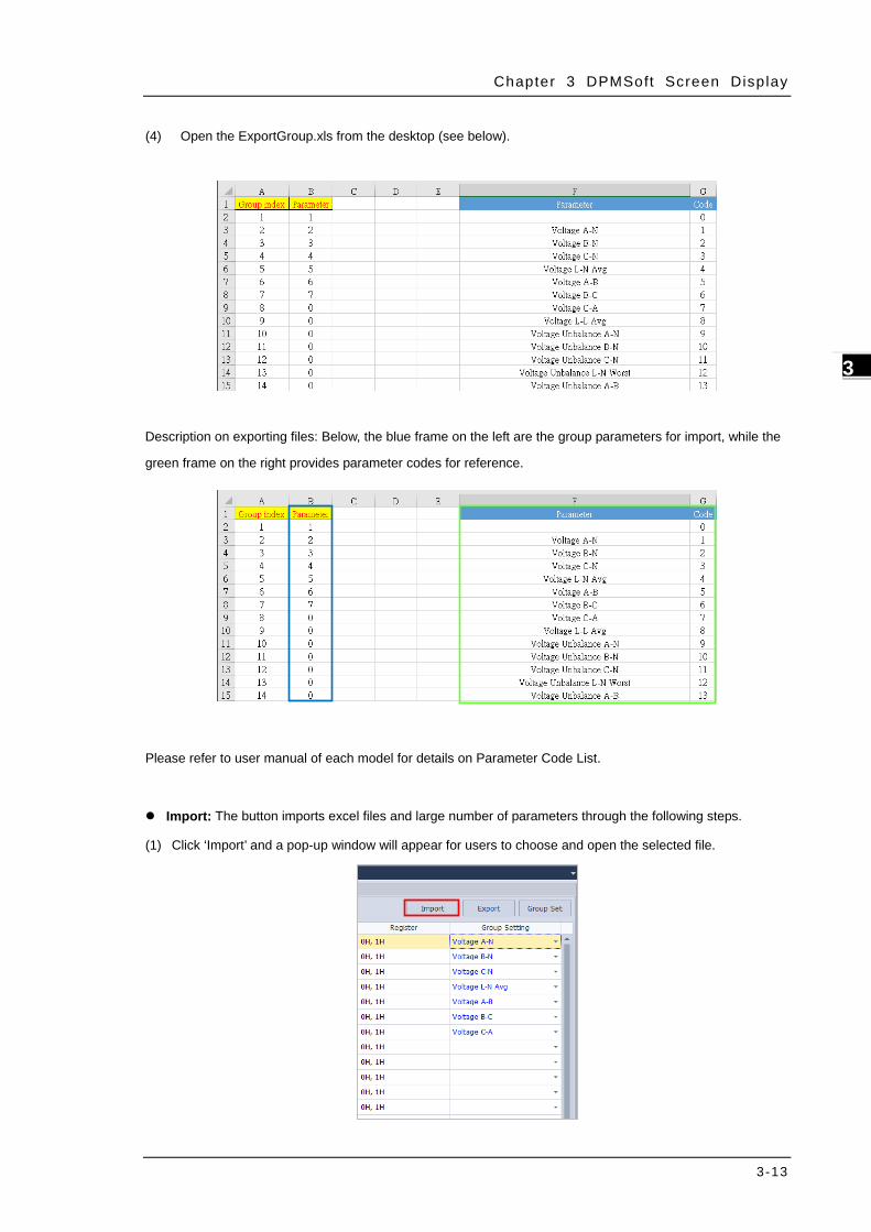
(4) Open the ExportGroup.xls from the desktop (see below).
Description on exporting files: Below, the blue frame on the left are the group parameters for import, while the
green frame on the right provides parameter codes for reference.
Please refer to user manual of each model for details on Parameter Code List.
Import: The button imports excel files and large number of parameters through the following steps.
(1) Click ‘Import’ and a pop-up window will appear for users to choose and open the selected file.
DPMSoft User Manual
3-14
_3
(2) The import process for the selected excel file starts and a diagram showing the current import progress
will appear.
(3) A pop-up window would appear when the group parameter is successfully imported. Click OK and the
selected parameter data can be viewed from the desktop.
3.14 Alarm History
The page displays the alarm history which the alarm data can be exported using a CSV file.
Click “Alarm History” in the project tree on the left side to enter the page (see below).
Export: Export all the alarm log data by following the steps below.
(1) Click the export button.
Chapter 3 DPMSoft Screen Display
3-15
3_
(2) A pop-up window for saving the export file would be displayed. Click save after choosing a path to save
the exporrted file, then the data export would be completed.
DPMSoft User Manual
3-16
_3
3.15 Tariff
The page displays the tariff point (P1), peak (P2), plateau (P3), valley (P4) for power usage as well on hourly
basis daily.
Click “Tariff” in the project tree on the left side to enter the page (see below).
3.16 Phasor Diagram
This page displays phasor difference between the applied voltages.
To enter the page, click “Phasor Diagram” in the project tree on the left hand side of the page as shown in the
following figure.
Chapter 3 DPMSoft Screen Display
3-17
3_
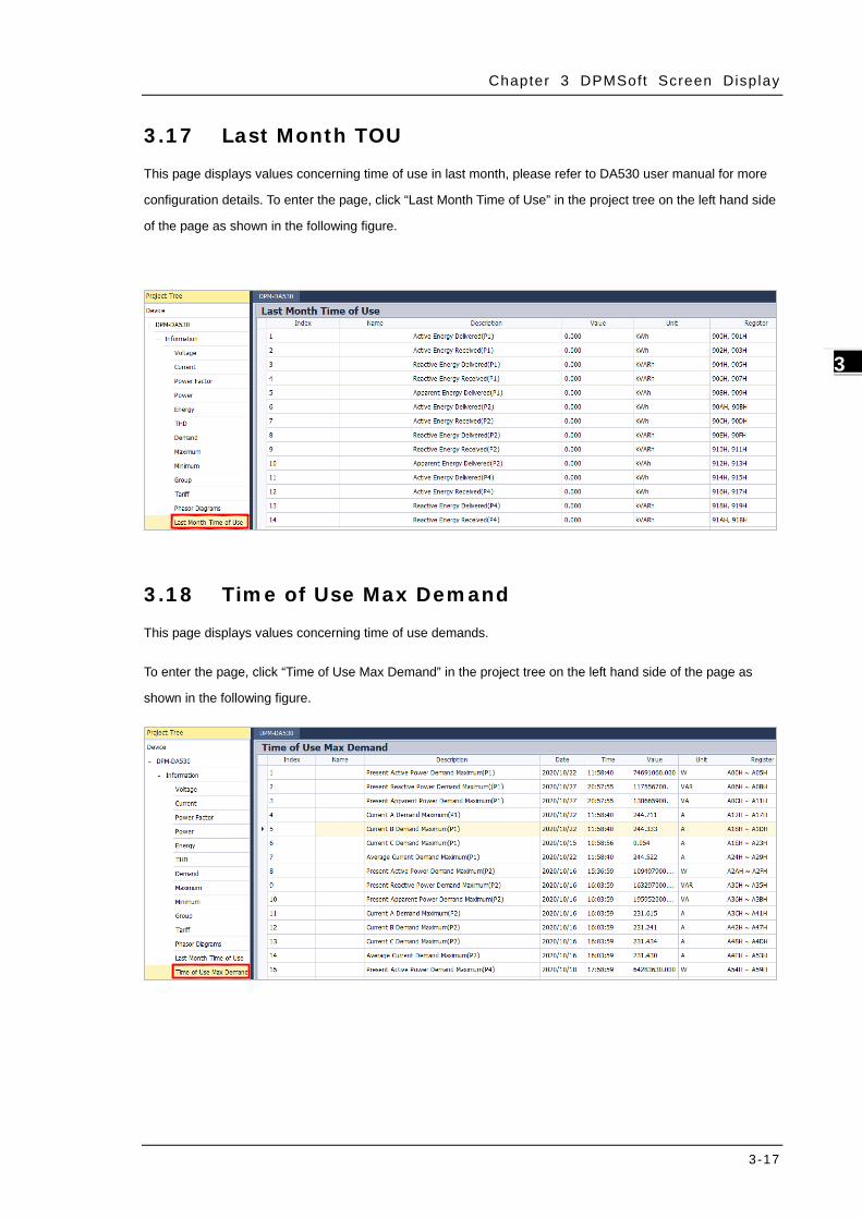
3.17 Last Month TOU
This page displays values concerning time of use in last month, please refer to DA530 user manual for more
configuration details. To enter the page, click “Last Month Time of Use” in the project tree on the left hand side
of the page as shown in the following figure.
3.18 Time of Use Max Demand
This page displays values concerning time of use demands.
To enter the page, click “Time of Use Max Demand” in the project tree on the left hand side of the page as
shown in the following figure.
DPMSoft User Manual
3-18
_3
MEMO
4-1
4 Chapter 4 DPMSoft Settings
Table of Contents
4.1 System Setting ..................................................................................... 4-3
4.1.1 Meter Information ........................................................................... 4-3 4.1.2 Transformer Ratio ........................................................................... 4-4 4.1.3 Current Transformer ........................................................................ 4-6 4.1.4 System ......................................................................................... 4-6 4.1.5 Power System ................................................................................ 4-7 4.1.6 Alarm ............................................................................................ 4-8 4.1.7 Communications ........................................................................... 4-11 4.1.8 Date ........................................................................................... 4-12 4.1.9 Demand ...................................................................................... 4-13 4.1.10 Meter Reset ................................................................................. 4-14 4.1.11 BACnet Device ID ......................................................................... 4-14 4.1.12 Settings for Wifi Reuters ................................................................ 4-15 4.1.13 DIDO Settings .............................................................................. 4-17 4.1.14 Ethernet ...................................................................................... 4-18 4.1.15. Pulse Output ................................................................................ 4-19 4.1.16 Default Page Display in the Meter .................................................... 4-20 4.1.17 Display Unit Format in the Meter ..................................................... 4-21 4.1.18 Display Unit Format....................................................................... 4-21 4.1.19 Value Low Cut .............................................................................. 4-22 4.1.20 Loop Quantity .............................................................................. 4-22 4.1.21 Back Light Time in the Meter .......................................................... 4-23 4.1.22 Custom Page Display in the Meter ................................................... 4-23 4.1.23 Data Word Order .......................................................................... 4-24
4.2.1 Auto Recording ............................................................................. 4-25 4.2.2 Auto Phase Sequence .................................................................... 4-26 4.2.3 Display of Numerical Values in the Meter .......................................... 4-26 4.2.4 Display Unit Format....................................................................... 4-27 4.2.5 EUI Setting .................................................................................. 4-27 4.2.6 Auto Reset Max and Min Interval ..................................................... 4-28 4.2.7 Energy Saving .............................................................................. 4-29 4.2.3 Tariff ........................................................................................... 4-30
DPMSoft User Manual
2
_4
4.2.9 Carbon Dioxide Emissions .............................................................. 4-31 4.2.10 Data Word Order .......................................................................... 4-32 4.2.11 Password Modification ................................................................... 4-33 4.2.12 Alarm ......................................................................................... 4-33 4.1.13 TOU ........................................................................................... 4-35 4.2.14 Custom Page in the Meter (Summary-P) .......................................... 4-37 4.2.15 Summary Display Order in the Meter ............................................... 4-38 4.2.16 Digital Input ................................................................................ 4-39 4.2.17 Relay Output Setting ..................................................................... 4-40 4.2.18 Back Light Time in the Meter .......................................................... 4-42 4.2.19 Reset Loop Parameter ................................................................... 4-42
4.3 Data Log............................................................................................ 4-43
4.4 Data Log-DA Series/MA Series .............................................................. 4-47
Chapter 4 DPMSoft Sett ings
4-3
4_
DPMSoft contains options including System Setting, Advanced Setting and Data Log for power meter setup,
which may differ from one model type to another. Please refer to the user manual of each product and the
following explanations for more details.
4.1 System Setting
Click System Setting in the project tree on the left side of the page to start the configuration.
4.1.1 Meter Information
Displays including meter model name, firmware version, date and operation time.
CT Primary: Set the primary CT within the range of 1 to 9999 A.
CT Secondary: Set the secondary CT within the available options of 1A, 5A and 2.5A.
PT Primary: Set the primary PT within the range of 1 to 99999 V.
PT Secondary: Set the secondary PT within the range of 1 ~ 9999 V.
Click Transformer Ratio Set when the setting is complete and a pop-up window appears showing whether the
setting is successful or not.
Via the setting window for multi-loop models, values of CT Primary, CT Secondary, PT Primary, PT Primary Unit
and PT Secondary for the target main loop or branch loop can be configured.
Click Detailed Settings to pop up the transformer ratio setting window.
Chapter 4 DPMSoft Sett ings
4-5
4_
After selecting the target main loop, modify the relevant parameters of the main and branch loops, then click
Main Loop Transformer Ratio Set. A pop-up window would appear showing whether the setting is successful
or not.
DPMSoft User Manual
4-6
_4
4.1.3 Current Transformer
The setting range for CT primary current is from 1 to 9999 A with 50 A being the factory default setting.
Click Current Transformer Set after finishing the primary current setting, then a pop-up window would appear
showing whether the setting is successful or not.
4.1.4 System
Please refer to the manual of each model for details on parameter settings of user interface and wiring.
Language: The display language on the user interface of the power meter.
Backlight: The brightness of the screen backlight. Timeout: When the user do not press the button on the power meter during the timeout, the
brightness of the screen backlight is based on the previous percentage setup, but when the button is pressed, the brightness of the screen backlight is 100%.
Power System: Power wiring.
Rotation: When current A and C are incorrectly wired, set the rotation parameter and rewire is not necessary.
Transformer Number: The number of CT & PT used in the system.
Chapter 4 DPMSoft Sett ings
4-7
4_
Click System Set when the setup is complete and a pop-up window appears showing whether the setting is
successful or not.
4.1.5 Power System
Configure parameters relevant to power system settings.
On the power system type setting window, select the desired power system type and assign voltage phases for
main and branch loops.
Click Detailed Settings to pop up Power System Type Setting window.
DPMSoft User Manual
4-8
_4
After completing the settings, click Main Loop Power System Type Set. A pop-up window would appear
showing whether the setting is successful or not.
4.1.6 Alarm
Setup the alarm parameters for the power meter.
Dropdown Menu: Select a required alarm from 29 alarm types.
Alarm Status: Set the alarm status.
Pickup: When higher than the pickup current, the alarm is enabled
Time Delay: When higher than the pickup current and exceeds the time delay, the alarm is enabled.
Dropout: When lower than the drop-out current, the alarm is disabled.
Time Delay: When lower than the drop-out current and exceeds the time delay, the alarm is disabled.
*Note: a.) Alarm Status: Options of Enable for Relay 1 Output, Enable for Relay 2 Output and Enable for
Relay 1 and 2 Output are only supported by version v1.0010 or later in DPM-C501 model and
DPM-C532. Set proper parameters in DIDO setting (please refer to section 4.1.13) and relay would
output relevant signals when the triggering condition is reached.
Chapter 4 DPMSoft Sett ings
4-9
4_
Steps to setting the alarm:
(1) Select an alarm type.
(2) Set Alarm Status to Enable.
(3) Define the values of Pickup and Time Delay.
DPMSoft User Manual
4-10
_4
(4) Define the values of Drop-out and Time Delay.
(5) Click “Alarm Set” when the setting is complete and a pop-up window appears showing whether the
setting is successful or not.
(6) Repeat steps (1) ~ (5) for settings regarding all the other alarm types.
Chapter 4 DPMSoft Sett ings
4-11
4_
4.1.7 Communications
Setup the communications parameters for the power meter.
Station: Modbus slave station ranges from 1~254. When using BACnet MS/TP as communication mode, the MAC ID ranges from 1~127.
Mode: Supports RS-485 protocol.
Baud Rate: Communication speed supports RS-485.
Data bit: Data length of packets.
Parity: The parity bit for RS485 communications.
Stop bit: Signal to indicate the end of data transmission.
Click “Communication Set” when the setting is complete and a pop-up window appears showing whether the
setting is successful or not.
DPMSoft User Manual
4-12
_4
4.1.8 Date
Provides date and time parameters for power meter setup.
Auto: Automatically sets the date and time based on the PC, no manual setting required. Manual: Manually select the time and date
Click “Date Time Set” when the setting is complete and a pop-up window appears showing whether the setting
is successful or not.
Chapter 4 DPMSoft Sett ings
4-13
4_
4.1.9 Demand
Setup methods for measuring power meter’s demand, which may differ from the model types. Please refer to
each model’s user manual for more details.
Method: Method for measuring power meter’s demands. Interval: Supports demand measuring interval time ranging from 1 to 60 min.
Click “Demand Set” when the setting is complete and a pop-up window appears showing whether the setting is
successful or not.
DPMSoft User Manual
4-14
_4
4.1.10 Meter Reset
Provides parameters regarding power meter reset.
Click “Reset Set” when the setting is complete and a pop-up window appears showing whether the setting is
successful or not.
4.1.11 BACnet Device ID
Supported models: DPM-C530, DPM-C530A
Setup the parameter for BACnet ID.
BACnet Device ID: The device identifier in BACnet MS/TP include 0 ~ 4194303.
Station: The MAC ID supports 1 ~ 127 stations for BACnet MS/TP mode.
Baud Rate: The speed of RS485 communications. If the setup is BACnet MS/TP mode, the default setting is 38400 bps.
Data bit: Data length of packets. For BACnet MS/TP mode, the default setting is 8 bit.
Parity: The parity bit for RS485 communications. For BACnet MS/TP mode, the default setting is None.
Stop bit: Signal to indicate the end of data transmission. For BACnet MS/TP mode, the default setting is 1 bit.
Chapter 4 DPMSoft Sett ings
4-15
4_
※ Note:
b.) Switch to BACnet MS/TP mode, the baud rate, data bit, parity and stop bit automatically change to its default setting in the order of 38400 bps, 8 bit, None and 1 bit.
c.) The BACnet MS/TP MAC ID and Modbus slave station shares the same parameter.
Click “BACnet Set” when the setting is complete and a pop-up window appears showing whether the setting is
successful or not.
4.1.12 Settings for Wifi Reuters
Supported models: DPM-C520W
The setting box is presented with router connection setups on the bottom right of the page.
Configure the settings of the target reuter you intend to connect, such as SSID and password, via DPMSoft with
DPM-C520W model wireless power meter.
SSID: Type the SSID name that connects the DPM-C520W to a router.
Password: Display the SSID password for connecting DPM-C520W to a router.
IP Address: The fixed IP address of DPM-C520W.
Keep Alive Time: If an inactive connection between master device and DPM-C520W power meter maintains over the keep alive time, the network will be disconnected automatically.
Default values of wireless communication settings are shown below:
DPMSoft User Manual
4-16
_4
SSID Password IP Address Keep Alive Time
Default Value WiFi_Modbus_001 1234567890 192.168.1.1 100sec
The Setting Range for wireless communication: Version SSID Password IP Address Keep Alive Time
Prior to V1.0008
(Not including
V1.0008 )
- - 192.168.X.1 -
V1.0008 and above 1~32
characters
8~16 characters
(or no-password )
AAA.BBB.XXX.YYY
(Range:1~255 ) 5 ~ 9999
Eplaination for IP Address Settings:
1. The hardware version of DPM-C520W is an earlier version before V1.0008:
Example A:
If the IP address is set to be 192.168.1.1 ; Station is 5, then the IP address for DPM-C520W would be
192.168.1.5
Example B:
If the IP address is set to be 192.168.0.1 ; Station is 10, then the IP address for DPM-C520W would be
192.168.0.10
2. The hardware version of DPM-C520W is V1.0008 and above:
Example :
If the IP address is set to be 168.234.123.10 ; Station is 5, then the IP address for DPM-C520W would be
168.234.123.10
Click “Connection Set” when the connection settings for the router is complete and a pop-up window appears
showing whether the setting is successful or not.
Chapter 4 DPMSoft Sett ings
4-17
4_
4.1.13 DIDO Settings
Configure the input and output settings of the power meter in DIDO setting box.
Enable DI1~DI4: To enable or disable digital input function.
Relay1~Relay2 Output: A high signal appears when DI enables or an alarm occurs.
None: The output function of relay 1 and 2 is disabled.
Alarm: The relevant relay output would be activated by an alarm condition.
DI1~DI4:The relay output is activated by an input signal detected in the specific DI.
Com: The output function is controlled by the software.
Multi Alarm: When the set alarm conditions are triggered randomly, the relay output would be activated.
DI1~DI4: DI status.
DO1~DO2 Status: The DO status shows lights off for open circuit, lights on for short circuit. Select ‘Com’ in ‘Relay Output’ drop-list first or the following error window will appear.
DPMSoft User Manual
4-18
_4
Methods for relay control setting via computers:
Select Com for Relay1 Ouput or Relay2 Out, then click “DIDO Set”.
4.1.14 Ethernet
Provides parameter settings regarding Ethernet.
To connect model types supporting Ethernet via DPMSoft, configure Ethernet settings presented on the bottom
right of the page. First, click “Set Detail Ethernet” then the Ethernet Setting window would pop up.
The Ethernet basic setting is on the left-hand half of the window, while the other half side gives the setting of IP
Filter. Only if the device’s IP address is in the range configured in the IP filter, it can be connected to the power
meter.
Chapter 4 DPMSoft Sett ings
4-19
4_
Click “Ethernet Set” after the configuration is completed. In case that the configuration is successful, it is
Parameter: Options are Active Energy Delivered, Active Energy Received, Inactive Energy Delivered,
Inactive Energy Received, and off.
Pre-Divider: The setting range is from 1 to 9999.
High Potential Duration (msec): The setting range is from 0 to 5000, which 0 represents that the
proportions of high and low potential are 50 percent respectively
DPMSoft User Manual
4-20
_4
Click “Pulse Output Set” when the settings for pulse output is completed and then a pop-up window would
appear showing whether the setting is successful or not.
4.1.16 Default Page Display in the Meter
Selected Page: Options are
Summary-1 (Voltage L-N average/ Current average/ Total effective power/ Power factor average/ Input effective energy)
Summary-2 (Voltage L-L average/ Current average/ Total effective power/ Power factor average/ Input effective energy)
Summary-3 (Total effective power/ Total ineffective power / Total apparent power / Power factor average/ Input effective energy)
Summary-4 (Total effective power/ Total ineffective power / Total apparent power / Frequency/ Input effective energy)
Click “Default Page Set” when the setting is completed and then a pop-up window would appear showing whether the setting is successful or not.
Chapter 4 DPMSoft Sett ings
4-21
4_
4.1.17 Display Unit Format in the Meter
Provides parameter settings regarding unit displayed in the power meter.
Click Unit Format Set when the setting is completed and then a pop-up window would appear showing
whether the setting is successful or not.
4.1.18 Display Unit Format
Set the unit format displayed in the meter and DPMSoft.
Click Unit Format Set when the setting is completed and then a pop-up window would appear showing
whether the setting is successful or not.
DPMSoft User Manual
4-22
_4
4.1.19 Value Low Cut
Set the percentage for current low cut. When the detected current value is lower than the set percentage, the
current value would be 0. The setting range is from 0.0%~100% with 0.4% being the factory default setting.
Click Value Low Cut Set when the setting is completed and then a pop-up window would appear showing
whether the setting is successful or not.
4.1.20 Loop Quantity
Enabled loop quantity set for power meter can be set from 1 to 5 loops with 5 being the factory default setting.
Click Loop Quantity Set when the setting is completed and then a pop-up window would appear showing
whether the setting is successful or not.
Chapter 4 DPMSoft Sett ings
4-23
4_
4.1.21 Back Light Time in the Meter
Set back light time from 0 to 15 minutes with 1 being the factory default setting, which 0 represents always on.
After set back light time based on your needs and click Back Light Time Set, a pop-up window would appear
showing whether the setting is successful or not.
4.1.22 Custom Page Display in the Meter
Select the desired parameter to display on the custom page in the meter.
Select Parameter: Select the parameter to display for the selected loop in the meter with DC Voltage
being the factory default setting.
Select Loop: Select the loop to display in the meter.
After finish settings for custom page display, click Custom Page Set and a pop-up window would appear
showing whether the setting is successful or not.
DPMSoft User Manual
4-24
_4
4.1.23 Data Word Order
Set Modbus word order for float and uint data type.
After finish the settings, click Data Word Order Set and a pop-up window would appear showing whether the
setting is successful or not.
4.2 Advance Setting
Click “Advanced Setting” in the project tree on the left side of the page to start the configuration.
Chapter 4 DPMSoft Sett ings
4-25
4_
4.2.1 Auto Recording
Auto recording monthly power usage.
Auto Recording 1 Enable: Check the checkbox to enable or disable auto recording 1.
Recording Day: Schedule a day (Day: 1~31) in a month to measure monthly power usage
regarding group 1.
Auto Recording 2 Enable: Check the checkbox to enable or disable auto recording 2.
Recording Day: Schedule a day (Day: 1~31) in a month to measure monthly power usage
regarding group 2.
Steps for auto recording:
(1) Choose a day (1~31) of a month to start recording.
(2) Click “Auto Recording1 Enable” and choose “Auto Recording 1 Set” (see below) to start auto recording 1.
(3) Repeat the same steps (1) ~ (2) for setting Auto Recording2.
※ Note:
a.) If the setting day exceeds the last day of that month, use the last day of that month instead.
b.) Calculation: Assume the calculation starts from on the 1st of this month, 0 hr 0 min 0 sec and
record the data to the last day of this month, 23 hr 59 min 59 sec. (The end day of the month varies
and is set on the 28th, 30th or 31st based on the month.)
DPMSoft User Manual
4-26
_4
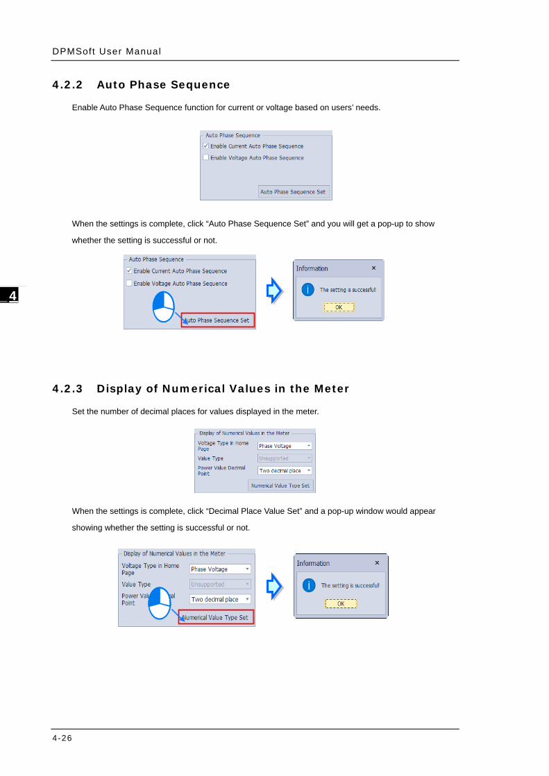
4.2.2 Auto Phase Sequence
Enable Auto Phase Sequence function for current or voltage based on users’ needs.
When the settings is complete, click “Auto Phase Sequence Set” and you will get a pop-up to show
whether the setting is successful or not.
4.2.3 Display of Numerical Values in the Meter
Set the number of decimal places for values displayed in the meter.
When the settings is complete, click “Decimal Place Value Set” and a pop-up window would appear
showing whether the setting is successful or not.
Chapter 4 DPMSoft Sett ings
4-27
4_
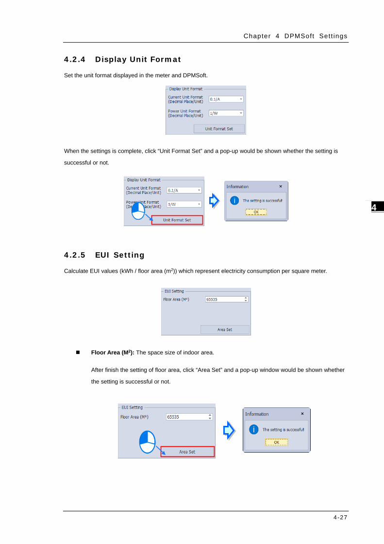
4.2.4 Display Unit Format
Set the unit format displayed in the meter and DPMSoft.
When the settings is complete, click “Unit Format Set” and a pop-up would be shown whether the setting is
successful or not.
4.2.5 EUI Setting
Calculate EUI values (kWh / floor area (m2)) which represent electricity consumption per square meter.
Floor Area (M2): The space size of indoor area.
After finish the setting of floor area, click “Area Set” and a pop-up window would be shown whether
the setting is successful or not.
DPMSoft User Manual
4-28
_4
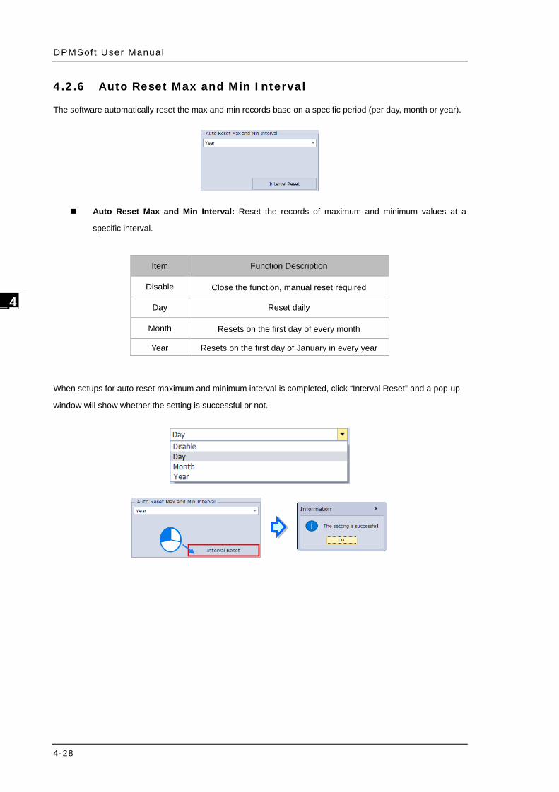
4.2.6 Auto Reset Max and Min Interval
The software automatically reset the max and min records base on a specific period (per day, month or year).
Auto Reset Max and Min Interval: Reset the records of maximum and minimum values at a
specific interval.
When setups for auto reset maximum and minimum interval is completed, click “Interval Reset” and a pop-up
window will show whether the setting is successful or not.
Item Function Description
Disable Close the function, manual reset required
Day Reset daily
Month Resets on the first day of every month
Year Resets on the first day of January in every year
Chapter 4 DPMSoft Sett ings
4-29
4_
4.2.7 Energy Saving
The current accumulated energy is categorized into normal or energy saving mode.
Enable Energy Saving: Select to enable or to close energy saving / non-energy saving mode.
Normal/ Energy Saving Mode: Switch the accumulated energy to either energy saving or non-energy saving mode.
The following describe the energy saving mode settings:
Choose “Enable Energy Saving” and “Normal Mode”. Then, click “Energy Saving Set” to enable this
function.
DPMSoft User Manual
4-30
_4
4.2.8 Tariff
Record energy based on the off-peak times.
Every Day Every Hour Energy Record Enable: Record accumulated energy per hour by day. Type: Select from the 4 types of tariff during a day including point (P1), peak (P2), plateau (P3) or
valley (P4).
Start Time: The starting time to record accumulated energy
End Time: The ending time to record accumulated energy.
The following steps describe the tariff settings:
(1) Select the desired “point (P1), peak (P2), plateau (P3) or valley (P4)” and setup the start and end time.
(2) Repeat step (1) regarding tariff setups for the 2nd to 8th group.
(3) When the setups are complete, click “Tariff Set”.
Chapter 4 DPMSoft Sett ings
4-31
4_
※ Note:
a.) When the start and end time are set to be the same, the tariff function is disabled.
b.) If the start time exceeds the end time (see below), this means the tariff is calculated till the next day.
4.2.9 Carbon Dioxide Emissions
Set the CO2 emission (kg) for each unit of electricity. The setting values range is from 0 to 60.000 with
0.638 being the factory default setting.
CO2 Emission (kg): Calculates the total emissions of carbon dioxide. CO2 Ratio (kg): Set the CO2 emission for each unit of electricity
DPMSoft User Manual
4-32
_4
When the setting for CO2 Ratio is completed, click “CO2 Ratio Set” and a pop-up window will show whether the
setting is successful or not.
4.2.10 Data Word Order
Set the Float and Uint data word order for Modbus transmission
When the setting for Data Word Order is completed, click “Data Word Order Set” and a pop-up window will
show whether the setting is successful or not.
Chapter 4 DPMSoft Sett ings
4-33
4_
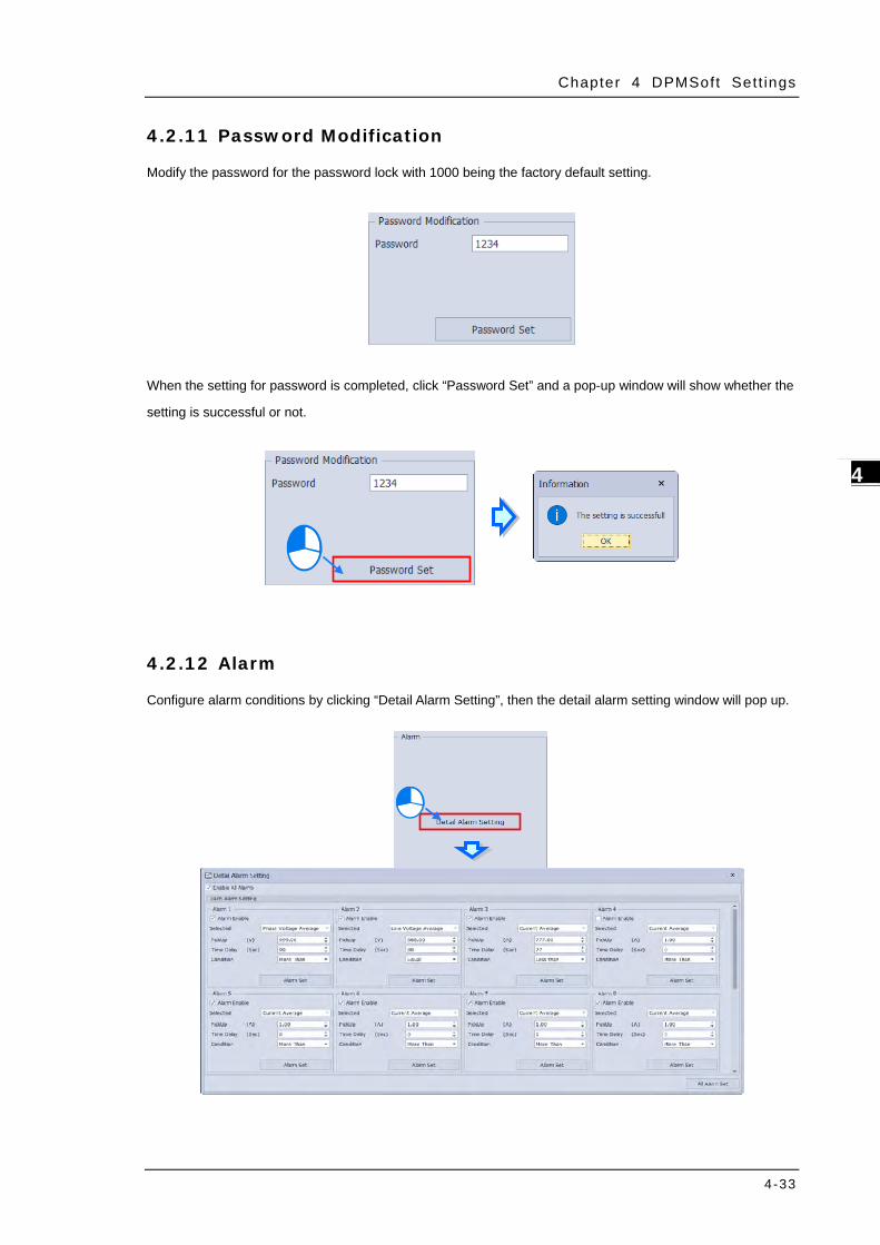
4.2.11 Password Modification
Modify the password for the password lock with 1000 being the factory default setting.
When the setting for password is completed, click “Password Set” and a pop-up window will show whether the
setting is successful or not.
4.2.12 Alarm
Configure alarm conditions by clicking “Detail Alarm Setting”, then the detail alarm setting window will pop up.
DPMSoft User Manual
4-34
_4
Alarm Enable: Check the box to enable or uncheck to disable the function. Selected: Choose the desired alarm option from the drop-down list. Pickup: The alarm is triggered when the condition and the pickup value is fulfilled. Time Delay: After the pickup value is reached as well as the time delay being exceeded, the alarm
will be shown. Condition: Set the triggering condition. Once the condition is fulfilled, the alarm will be triggered.
When the alarm setting is completed, click “Alarm Set” or “All Alarm Set” and a pop-up window will show
whether the setting is successful or not.
Chapter 4 DPMSoft Sett ings
4-35
4_
4.1.13 TOU
Divide a certain time into consecutive time periods. Each period can point to the same or different tariffs (point,
peak, plateau or valley). The power meter respectively measures electricity based on different types of tariff,
which is determined by the internal clock inside the power meter, so as to meet the requirement of TOU
measurement and charge.
To set the TOU conditions, click “Detail TOU Setting” and then the detail TOU setting window would pop up.
DPMSoft User Manual
4-36
_4
There’re four sections on the detail TOU setting window as the following shows:
Parameter: Enable or disable the TOU function. A maximum number of 4 can be set for enabled time zone, while a maximum number of 8 can be set for enabled daily timetable. After complete the settings for time zone, daily timetable and settlement day, click “Parameter Set” to confirm successful save of configuration.
Annual Time Zone: A year can be divided into four time intervals at most, which must be configured in closed-loop. Make sure the setting of start date matches the setting in day timetable parameter. Furthermore, daily timetable number in Saturday and Sunday can also be configured here. After complete all the settings, click “Annual Time Zone Set” to confirm successful save of configuration.
For example, in case of three time zones being chosen, the first time zone is set to January 1st and group1 as the daily timetable, while the second time zone is set to September 9th and group3 as the daily timetable, as well as setting the third time zone to June 6th and group2 as the daily timetable, error occurs.
Daily Timetable Parameter: A day can be divided into eight time intervals at most, which must be
configured in closed-loop. Make sure each interval matches a proper tariff number. After complete all the settings, click “Daily Timetable Set” to confirm successful save of configuration.
Special Days: Can be configured with multi-year or single-year setting. Up to 20 special days can be configured in a setting, while a maximum of 5 years can be set for multi-year. After complete all the settings and make sure to match the daily timetable, click “Special Days Set” to confirm successful save of configuration.
Priority of TOU: Special days > Weekends > Annual Time Zone
Chapter 4 DPMSoft Sett ings
4-37
4_
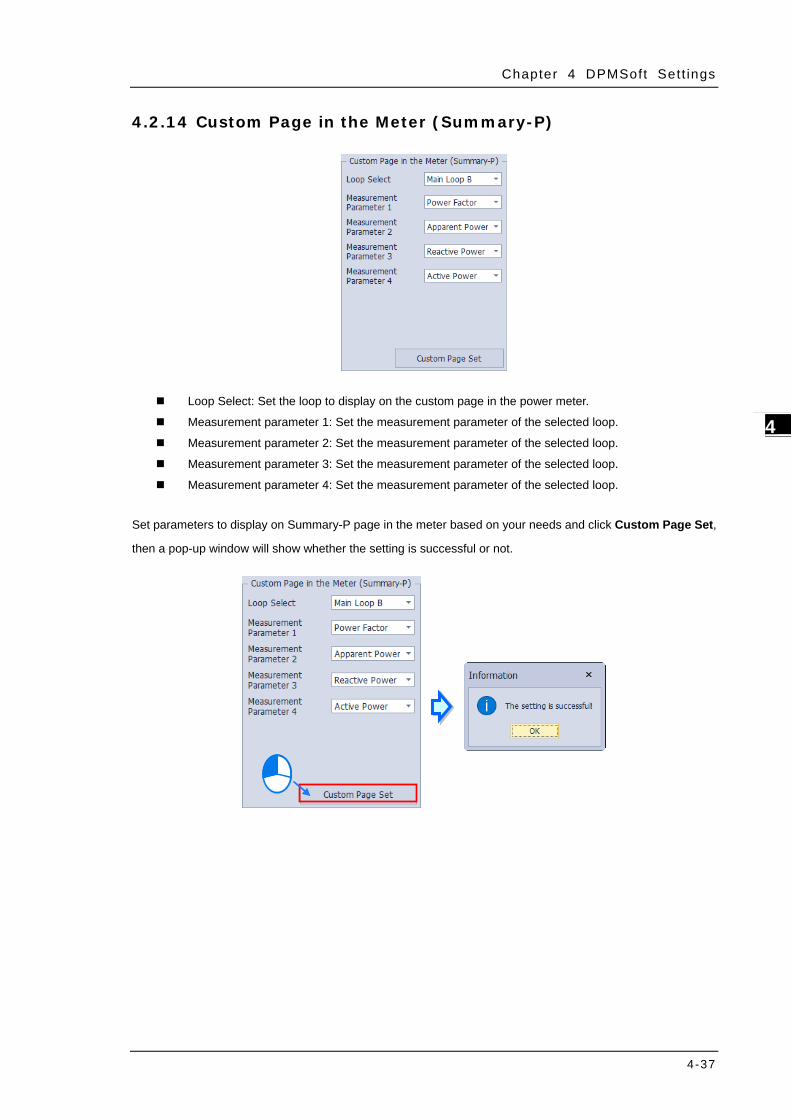
4.2.14 Custom Page in the Meter (Summary-P)
Loop Select: Set the loop to display on the custom page in the power meter.
Measurement parameter 1: Set the measurement parameter of the selected loop.
Measurement parameter 2: Set the measurement parameter of the selected loop.
Measurement parameter 3: Set the measurement parameter of the selected loop.
Measurement parameter 4: Set the measurement parameter of the selected loop. Set parameters to display on Summary-P page in the meter based on your needs and click Custom Page Set,
then a pop-up window will show whether the setting is successful or not.
DPMSoft User Manual
4-38
_4
4.2.15 Summary Display Order in the Meter
Set the orders of parameters displayed on summary page.
Select the default summary page: Configure loops and parameters displayed on the meter screen, and the options are:
Summary-1 (Average L-L voltage/Average three-phase current/Transient total actual power/ Frequencies)
Summary-2 (Transient total actual power/ Transient total virtual power/ Transient total apparent power/ Total real power factor)
Summary-3 (Average L-L voltage/Average three-phase current / Transient total apparent power/ Total real power factor)
Summary-4 (Average L-L voltage/Average three-phase current/Transient total actual power/ Frequencies)
Summary-5 (Transient total actual power/ Transient total virtual power/ Transient total apparent power/ Total real power factor)
Summary-6 (Average L-L voltage/Average three-phase current/Transient total actual power/ Total real power factor)
Summary-P (User-defined page); slide shows.
Slide Show (s): Set screen display length for slide shows.
Summary-1: Configure the parameter value of the selected loop displayed for Summary-1.
Summary-2: Configure the parameter value of the selected loop displayed for Summary-2.
Summary-3: Configure the parameter value of the selected loop displayed for Summary-3.
Summary-4: Configure the parameter value of the selected loop displayed for Summary-4.
Summary-5: Configure the parameter value of the selected loop displayed for Summary-5.
Summary-6: Configure the parameter value of the selected loop displayed for Summary-6.
Configure the default display based on your needs and click Summary Display Order Set, then a pop-up
window will show whether the setting is successful or not.
Chapter 4 DPMSoft Sett ings
4-39
4_
4.2.16 Digital Input
The meter comes standard with two digital inputs, including DI1 and DI2. Apart from being digital inputs, you
can also configure the conditions for them.
The upper section is to configure DI1 digital input settings and the lower section is to set DI2 digital input.
Function: Digital Input, Demand Reset, Max Demand Reset, Energy Reset, Max/ Min Reset/ Relay
Reset with Digital Input being the default factory setting.
Trigger Level: The input signal can be set to either ON (High) or OFF (Low).
Debouncing Time(x8 ms): Set the debounce time to avoid errors with a setting range from 0 to 99 (x
8mS), while 5 (40mS) being the default factory setting.
Configure the digital input settings based on your needs and click Digital Input Set, then a pop-up window will
show whether the setting is successful or not.
DPMSoft User Manual
4-40
_4
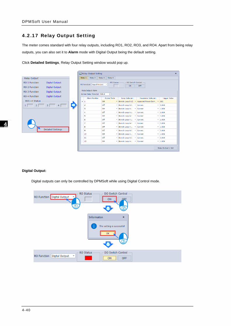
4.2.17 Relay Output Setting
The meter comes standard with four relay outputs, including RO1, RO2, RO3, and RO4. Apart from being relay
outputs, you can also set it to Alarm mode with Digital Output being the default setting.
Click Detailed Settings, Relay Output Setting window would pop up.
Digital Output:
Digital outputs can only be controlled by DPMSoft while using Digital Control mode.
Chapter 4 DPMSoft Sett ings
4-41
4_
Alarm:
You can set the active delay time from 0 to 599.9 with 0 being the default factory setting.
A maximum of 12 conditions can be set for each relay output, which include Active Mode, Loop
Selection, Parameter Selection and Trigger Value.
Active Mode: Set a proper condition with options: Off, Low Active, High Active, Low Active
and Remain, High Active and Remain.
Loop Selection: Set the alarm loops.
Parameter Selection: Set the parameters of alarm loops.
Trigger Value: Set the alarm trigger values.
Configure the relay output settings based on your needs and click Relay Output Set, then a pop-up window
will show whether the setting is successful or not.
DPMSoft User Manual
4-42
_4
4.2.18 Back Light Time in the Meter
Set the desired backlight time setting with values ranging from 0 to 15 minutes. 0 represents always ON and
the default factory setting is 1.
Configure the backlight time settings based on your needs and click Back Light Time Set, then a pop-up
window will show whether the setting is successful or not.
4.2.19 Reset Loop Parameter
Reset loop parameter settings.
Loop: Select the target loop to reset.
Parameter: Select the target parameter.
Configure the reset loop parameter settings based on your needs and click Reset, then a pop-up window will
show whether the setting is successful or not.
Chapter 4 DPMSoft Sett ings
4-43
4_
4.3 Data Log
Store the logs regarding parameters in the non-volatile memory (NVM) and download the data logs via
RS-485 communications.
There’re three sections on the data log window:
Data Log Interval
Start Date Time: The time and date to enable data log. Interval: Record the interval of the power meter, with the minimum interval as 0 (min):5 (sec), the
maximum interval as 60 (min):0 (sec). If the interval is set as 0 (min):0 (sec), this means the interval function is disabled.
Read Data Log
Read and Save: The exported logs are in CSV format and select a download location.
Data Log Setting
Data Log Setting 01~17: Choose from up to 17 content parameters and sequence for data storage.
DPMSoft User Manual
4-44
_4
Data Log Specification:
Interval
Item
0 min 0 sec ~ 0 min 59
sec
1 min 0sec ~ 4 min 59
sec
5 min 0 sec ~ 60 min 0
sec
Maximum Parameters
(number) 6 17 17
Maximum Capacity (Day) 7 31 62
Setup data log through the following steps:
(1) Select the desired parameters in the order 01 to 17 from the data log setting section and base on the
above specifications for data storage.
Chapter 4 DPMSoft Sett ings
4-45
4_
(2) Click “Set Data Log Setting” (see below) to complete the setting.
(3) Select the desired data log interval and click “Store Internet Set” to complete the settings.
(4) You can click “Read and Save” to download the data log onto your PC.
DPMSoft User Manual
4-46
_4
(5) Choose the data log file and download location, then click “Save”.
(6) A successful message would appears at the bottom of the page when the download is complete.
※ Note:
a.) First complete the “Data Log Setting 01~17”to setup the sequence and then select the “Interval”. If
“Interval” is set first, then “Data Store Setting 01~17” cannot be setup. ("Set Data Log Setting”
button cannot be clicked )
b.) When the data store setting exceeds the specification, the exceeding content is ignored. In other
words, if the interval is set at 5 sec, the data store setting from 07 and more are automatically
ignored.
Chapter 4 DPMSoft Sett ings
4-47
4_
4.4 Data Log-DA Series/MA Series
As the data log configuration for DA and MA Series power meter is different from other model types, a further
introduction is given in this section.
Click “Data Log” to enter the page as shown in the figure below.
There’re three sections on the data log page for DA and MA series power meter.
DPMSoft User Manual
4-48
_4
Data Log Internal
Record Status: Active or stop recording status. Start Time: Set the time to start storing records. End Time: Set the time to stop storing records Interval Unit: Set the unit of interval between two records, which can be set to Second, Minute, Hour
and Day. Interval Time: Set the interval time between two records, the setting range is from 1 to 32767.
Total Number of Records: Display the current number of records.。
Read Data Log
Download Location: Select the desired storage path before export the data log to a CSV file.
Data Log Setting:
Data storage setting 01~50: Select the desired contents and sequences for parameters to be stored, with 90 sets of parameters at maximum.
※ Note: Make sure that the condition setting has been completed as well as the record function being enabled before using the data log function. Any incomplete or incorrect configuration may result in recording errors ultimately. The configuration should be completed through the corresponding register, while the register must be configured via communication protocols. By following first-in-first-out principle, the earlier records would be covered sequentially when the number of records reaches the limit. Therefore, we suggest you to read and save all the record data before the maximum limit of records is reached so as to prevent data loss.
When the parameter setting of data log internal is changed, all the current record data would be erased and immediately begin a new recording. In case that you intend to modify the data log internal setting, it is necessary to turn off record function by setting “Record Status” to “Stop”.