DR. BENDER GmbH & Co. KG Innovative Elektrowerkzeuge Manual for drilling motor BBM 33 L extra 230 V Valid from 08.2002 Art.-Nr. 200664 Subject to alterations All rights reserved DR. BENDER GmbH & Co. KG • D-75382 Althengstett • Tel 07051-9291-0 • Fax 07051-9291-91 Our website address is: http://www.dr-bender.de • eMail: [email protected]
Transcript
DR. BENDER GmbH & Co. KGInnovative Elektrowerkzeuge
Manual fordrilling motor BBM 33 L extra
230 VValid from 08.2002 Art.-Nr. 200664 Subject to alterations
All rights reservedDR. BENDER GmbH & Co. KG • D-75382 Althengstett • Tel 07051-9291-0 • Fax 07051-9291-91
Our website address is: http://www.dr-bender.de • eMail: [email protected]
DR.BENDER GmbH & Co. KG, as manufacturer, hereby declares that the electrical stone processing ma-chine mentioned above comply with the requirements of the following guidelines:
The following standards were applied for evaluating the machines:
a) with regard to the machine guidelines:VDE 0740 21-22: 1994-1991VDE 0701 Part 1: 1993VDE 0702 Part 1: 1995DIN EN 50144-1: 1999DIN EN 50144-2-1: 2000
b) with regard to electromagnetic compatibilityInterfering emissionsDIN EN 55014-1: 2000 + A1: 2001 = VDE 0875 Part 14-1DIN EN 61000-3-2: 2000DIN EN 61000-3-3: 1995 + Cor.1: 1997 + A1: 2001
Interference immunityDIN EN 55014-2: 1997 + A1: 2001 = VDE 0875 Part 14-2
c) with regard to the low voltage guidelineEN 61029-1: 2001
This declaration implies no assurance of properties.Please observe the safety regulations of the attached product documentation.
3
Contents
pageConformity declaration 2Contents 3
1.0 Symbol- and Pictograph description 41.1 Function description 42.0 General instructions 52.1 Application 52.2 Safety 53.0 Transport and storage 63.1 Transport 63.2 Storage 64.0 Main dimensions and technical data 74.1 Dimensions 74.2 Technical data 74.3 Noise emissions and vibrations [EN 50144] 85.0 Commissioning 85.1 Changing gear 95.2 Safety coupling 95.3 Core bits 95.4 To change a core bit 96.0 Safety instructions 107.0 Servicing and care 117.1 Daily care 117.2 After approx. 150 hours of use 117.3 After approx. 250 hours of use 117.4 Quarterly 118.0 Speed adjustment dependent on the cutting speed 129.0 Warranty 1310.0 General safety instructions 1411.0 Spare parts list 1611.1 Motor complete 1611.2 Gear complete 1811.3 Connection cables and accessories 20
4
WarningIt is compulsory to observe the safety instructions included in this manual!
Special designs and versions may differ from the standard models in terms of their technical de-tails. If any points are unclear, we urgently recommend that you contact DR.BENDER GmbH & Co.KG, indicating the machine type and machine number.
1.0 Symbol- and Pictograph description
This sign tells you rules, if you not pay attention for this your health and the function ofthe machine is in danger. You have no warranty if the machine breaks down becauseyou not looking about this.
1.1 Function description
Drill-spindle
Nameplate
Switch on/off
Water connection
Circuit breaker andPRCD switch
Gear control
5
2.0 General instructions
2.1 Application
The core drills can be used for the purposes outlined by the data on the model plate. If you are using spe-cial machines, the details in the quotation and order confirmation also apply. The core drills are supplied as standard in protection class I, only this can guarantee the full high qualityproduction of the residual current-operated circuit-breaker or PRCD switch. If you use suitable core bits, you will be able to drill holes in the most diverse material types:
- Concrete (even if it contains thick reinforcement steel) - Sandstone and limestone - All building materials for solid walls - Asphalt floors
The core drills comply with the regulations issued by the ”Stone and Earth” Professional Association issuedin July 1989. They are machines of category II, which means that they must be placed on stands and bestable (pursuant to DIN 57100 or VDE 0100), the stand must be equipped with
- a reversing block, and - a water suction device.
The machine must be connected to the 230 V mains
- direct using a personal safety switch (residual current-operated circuit-breaker or PRCD), or - using a coded (1h) plug to a safety box (IP 44) with a residual current-operated circuit-breaker.
2.2 Safety
WarningBefore using the machine for the first time, check that the conformity of the dataon the model plate with the mains voltage and frequency. Voltage deviations of ±5 % and/or voltage deviations of ± 2 % are permissible. Repairs must only be
completed by quality persons who have suitable training and qualifications.
The following points are to be given special attention:- the technical data and details of the permitted use of the machine (commissioning, ambient and
operating conditions) which are set out in the catalogue, the operating manual, the model platedata and other product information,
- the relevant accident prevention regulations- the correct use of tools- the use of personal safety equipment
6
3.0 Transport and storage
3.1 Transport
WarningThe core drills are to be checked for signs for transport damage on receipt. Anydamage must be documented in writing.
3.2 Storage
If possible, the storage site should be dry, clean and have a constant temperature. To ensure that the filmof lubricant in the bearings and sealing system is not lost, the motor shaft should be turned through severalrevolutions by hand after a lengthy period of storage, for example at monthly intervals. The roller bearingsin the motors should be replaced (or regreased) if the period between delivery and commissioning is overfour years. If the machines are stored in adverse conditions, this period may differ considerably.
7
4.0 Main dimensions and technical data
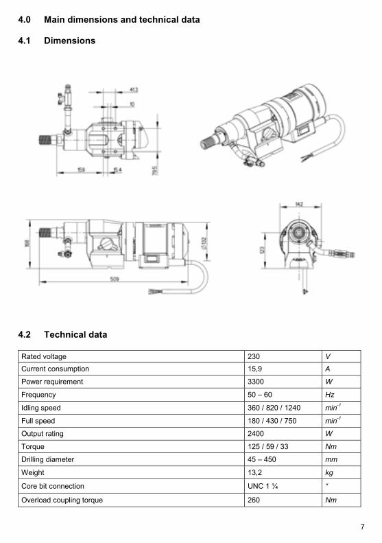
4.1 Dimensions
4.2 Technical data
Rated voltage 230 VCurrent consumption 15,9 A
Power requirement 3300 W
Frequency 50 – 60 Hz
Idling speed 360 / 820 / 1240 min-1
Full speed 180 / 430 / 750 min-1
Output rating 2400 W
Torque 125 / 59 / 33 Nm
Drilling diameter 45 – 450 mm
Weight 13,2 kg
Core bit connection UNC 1 ¼ “
Overload coupling torque 260 Nm
8
4.3 Noise emissions and vibrations [EN 50144]
Noise level Noise level VibrationdB(A) dB m/s2
82 96 < 2,5
5.0 Commissioning
Check that the mains voltage is identical to the voltage specified on the model plate.Secure the core drill and the water collector to the drilling stand with its reverse block. The drilling standshould be as rigid as possible and have precise, low-play guides. Ensure that the core drill axis is parallelto the axis of the drilling stand.Insert the core bit and set the speed. The setting instructions are on page 12.Connect the water supply. Important: Do not exceed the maximum water pressure of 3 bar.Connect the core drill to the mains using a residual current-operated circuit-breaker box and 1 h coded plugor a PRCD safety switch. Only use three-core extension cables with a protective conductor and an ade-quate cross-section. If the cross-section is too low, you may lose excessive power and result in the motorand cable overheating. An extension cable must have an overload cut-out switch. Recommended cablecross-sections:
Ensure that you have sufficient cooling water for drilling. Only use pure tap water, do not use dirty or wastewater. Adjust the feed speed to the core bit diameter and the drive rating of the core drill so that the ratedcurrent is not exceeded.
9
5.1 Changing gear
WarningNever change gear using force and only do so when the machine is slowingdown or at a standstill.
To change into the next higher or lower gear, move the gear-change lever through an angle of approx. 50°.If necessary (if the gear is difficult to engage), turn the drive spindle briefly by hand until the gear engageseasily.Do not use any tools (pliers, hammer, etc.) to change gear since otherwise gear damage is a natural con-sequence.
5.2 Safety coupling
The values set out in the table are theoretical values and may be used to provide a rough guide for gearchanging. Since a whole range of other parameters also plays a major role in adjusting the speed, we can-not offer any guarantee if the tool is damaged when using the values in the table. Drilling work for which thespeeds are outside the range of the core drill (values printed in italics), should only be completed with ex-treme care and by trained personnel.
5.3 Core bits
All core bits with a connection thread of 1 ¼ ” UNC can be used. Adapters can be supplied to allow core bits with other connection systems to be used. Only use core bits that are suitable for the type of stone. You will keep the core drill in good condition if you only use core bits that are concentric and not deformedones. Ensure that the diamond segments have an adequate undercut against the core bit body.
WarningTo use wrong tools or accessories is danger for your life.
5.4 To change a core bit
The drill spindle has a right-handed thread.Always use a 32 mm open-ended spanner to hold against the drill spindle.Never release the core bit with (hammer) blows since this will damage the core drill.The core bit can be removed more easily if you apply a little waterproof grease to the drill spindle thread.
10
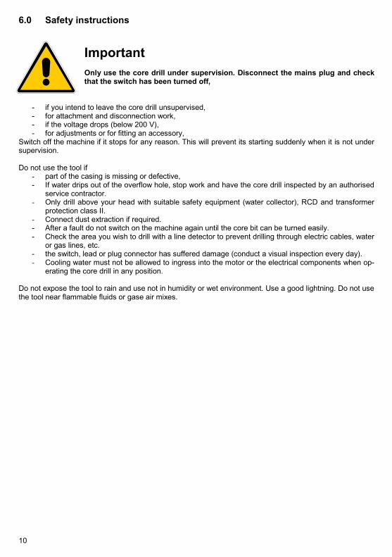
6.0 Safety instructions
ImportantOnly use the core drill under supervision. Disconnect the mains plug and checkthat the switch has been turned off,
- if you intend to leave the core drill unsupervised,- for attachment and disconnection work,- if the voltage drops (below 200 V),- for adjustments or for fitting an accessory,
Switch off the machine if it stops for any reason. This will prevent its starting suddenly when it is not undersupervision.
Do not use the tool if- part of the casing is missing or defective,- If water drips out of the overflow hole, stop work and have the core drill inspected by an authorised
service contractor.- Only drill above your head with suitable safety equipment (water collector), RCD and transformer
protection class II.- Connect dust extraction if required.- After a fault do not switch on the machine again until the core bit can be turned easily.- Check the area you wish to drill with a line detector to prevent drilling through electric cables, water
or gas lines, etc.- the switch, lead or plug connector has suffered damage (conduct a visual inspection every day).- Cooling water must not be allowed to ingress into the motor or the electrical components when op-
erating the core drill in any position.
Do not expose the tool to rain and use not in humidity or wet environment. Use a good lightning. Do not usethe tool near flammable fluids or gase air mixes.
11
7.0 Servicing and care
Warning Disconnect the mains plug before commencing any servicing or repair work.You must have the core drill checked by an electrician after every repair (statu-tory regulation pursuant to VBG4 since 1.1.1990).
7.1 Daily care
Ensure that no water is emitted from the overflow hole. This will cause gear damage and may adverselyaffect the electrical safety of the core drill. If water is emitted, see assistance from an authorised serviceoutlet. Visual inspection for damage to the switch, connection lead or plug connector After completing the drilling work clean the core drill. Grease the core bit mounting thread. The ventilationslits must always be clean and open. Ensure that during the cleaning process, no water gets into the coredrill. To maintain the seal, oil the drilling spindle as follows
- Disconnect the core drill from the water supply. Open the water connector shut-off cock, addseveral drops of oil, close the shut-off cock, add several drops of oil to the overflow hole andturn the machine briefly by hand.
7.2 After approx. 150 hours of use
After the first 150 hours of use, the gearbox oil must be changed.
7.3 After approx. 250 hours of use
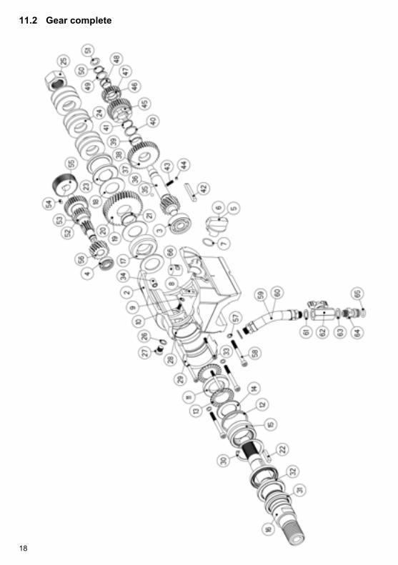
Have the carbon brushes checked, and replaced if necessary, by an electrician.- Remove the screw (16), remove the screws (15). By inserting a screw (15) into the thread
(16), pull the bearing cap (12) off the motor casing (2). Remove the carbon brushes screws(9), raise the carbon brushes retaining springs and take out the carbon brushes (7). Clean thecarbon brush holder and collector with a paintbrush.
- Fit new carbon brushes following the above instructions in reverse. Position the bearing cap(12) and secure it with the screws (15). Fit the bearing cap (12) on the motor casing (2) bytapping it gently with a rubber mallet or the like. Tighten the screws (15). Release the stressby tapping the bearing cap (2) twice. Turn in the screw (16) again.
Avoid adjusting the carbon retaining springs. Only use original spare parts.
7.4 Quarterly
Have the cable, switch and plug connectors inspected by a specialist (regulation pursuant to VBG4) anddocument this inspection. Changing the gearbox oil will produce a considerably increase in the service lifeof the gear.
12
8.0 Speed adjustment dependent on the cutting speed
The values set out in the table are theoretical values and may be used to provide a rough guide for gearchanging. Since a whole range of other parameters also plays a major role in adjusting the speed, we can-not offer any guarantee if the tool is damaged when using the values in the table. Drilling work for which thespeeds are outside the range of the core drill (values printed in italics), should only be completed with ex-treme care and by trained personnel.
Bit capacifity ø concrete concrete rock[mm] reinforced
13
9.0 Warranty
In keeping with our terms of sale, we offer a warranty for six months from the date of sale. This refers to thefree repair of material and workmanship defects, which were verifiably caused before the sale.
An original purchase document must always be submitted in case of a warranty claim. It has to contain thefull address of the dealer, the date of purchase and the type designation of the product. The operating in-structions of the particular product and the safety instructions must have been followed.
Damages resulting from operational faults cannot be acknowledged as warranty cases.
The products of the manufacturer have been developed and produced for specific applications. No war-ranty claim is accepted in case of non-compliance with the due employment according to the operating in-structions, in case of the employment for other purposes than originally intended or the employment of in-adequate accessories.
The periodical maintenance and cleaning of the products according to the directions of the operating in-structions is absolutely necessary. The intervention of third persons (opening the machine) renders anywarranty claim void.
Maintenance and cleaning operations cannot be claimed on the basis of warranty.
Make sure only original spare parts and original accessories are used. They are available at the authorizedspecialized product dealer. If non-original parts are used, consequential damages and increased hazardcannot be ruled out. The producer is not liable for such damages. Disassembled or partially disassembledhand saws and those repaired with non-original parts are excluded from the warranty.
Certain components, such as carbon brushes, ball bearings, switches, power-supply lines, gaskets, etc.,are exposed to usage dependent or to normal wear. These wearing parts are not object of this warranty.Wearing parts are marked on the spare parts lists.
14
10.0 General safety instructions
1. Read and follow these instructions before you use the tool. Keep these safety instructions in a safeplace.
2. Keep your workplace tidy. Untidiness in the workplace can cause accidents.3. Protect yourself from electric shocks. Refer to the applicable regulations. Avoid physical contact with
earthed parts, such as pipes, heaters, furnaces and refrigerators.4. Keep children away. Do not allow other people to touch the tool or cable, keep them away from
where you are working.5. Keep your tools in a safe place. Unused tools should be kept in a dry, locked room out of the reach of
children.6. Do not overload your tool. It will work better and more safely in the specified capacity range.7. Use the correct tool. Do not use tools that are too weak or mounted tools for heavy work. Do not use
tools for purposes and work for which they have not been designed.8. Wear suitable clothing. Do not wear excessively baggy clothing or jewellery, which may be caught by
moving parts. For working outdoors, we recommend the use of rubber gloves and sturdy shoes.Wear a hairnet if you have long hair.
9. Use goggles. Use a breathing mask for work that generates dust.10. Do not use the cable for any purpose other that that for which it is designed. Do not carry the tool by
the cable and do not use it to pull the plug out of the socket. Protect the cable from heat, oil andsharp edges.
11. Check the connection lead and plug every time before you use the tool for signs of damage. If theyare damaged, have them replaced by a specialist. Always keep the connection lead away from theworking area of the machine.
12. Secure the workpiece. Use clamps or a vice to hold the workpiece. This will make it more secure thatif you hold it in your hand and will allow you to use both hands to control the machine.
13. Do not overstretch yourself. Avoid abnormal body positions. Ensure that you have a stable area onwhich to stand and keep your balance at all times.
14. Look after your materials with care. Keep your tools sharp and clean so that they produce good saferesults. Check the plug and cable at regular intervals and have them replaced by a specialist if theysuffer any damage. Check the extension cable at regular intervals and replace damaged cables.Keep the handles free of oil and grease.
15. Disconnect the mains plug from the supply when the tool is not in use and when changing the tool.15. Do not leave a tool spanner on the tool. Before switching on the tool check that the wrench and set-
ting tools have been removed.16. Avoid the machine starting when you do not intend it to. Do not carry a tool that is connected to the
mains supply with your finger on the switch. Ensure that the switch is turned off when you connectthe tool to the mains supply.
18. Electric tools outdoors and in wet areas: Mobile tools which are used outdoors should be connectedto the mains supply using a residual-current circuit breaker or the like for added safety. This is par-ticularly important when working with freehand tools. If there is a water supply, you should use anisolation transformer and a voltage supply of 115 V; please specify in your order.
19. For outdoors work, only use extension cables, which are approved for this purpose and marked ac-cordingly.
20. Be vigilant at all times. Watch your work. Proceed sensibly. Do not use the tool if you are not con-centrating fully on what you are doing.
21. Important:Safety equipment (such as overcurrent protection devices, undervoltage trips, safety couplings etc.)are tools but do not offer guaranteed safety. As a responsible manufacturer we tailor these tools toeach other so that they offer the best possible protection. But without the care and caution of the use,these tools may even cause damage it they are not used properly. Have the slip couplings, in par-ticular, checked during the quarterly inspection to ensure that it is correctly adjusted and functionsproperly. This inspection should be conducted by the manufacturer or an authorised service outletand documented.
15
22. Check the machine every day for signs of damage, conduct a visual inspection:Before reusing the tool, carefully check the safety equipment or slightly damaged parts to ensure thatthey offer perfect and proper function. Check that all moving parts function correctly, that they do notjam and that none of the parts are damaged. All parts must be correctly fitted and satisfy all the con-ditions to ensure the perfect operation of the tool. Damaged safety equipment and parts must be re-paired or replaced properly by a specialist service contractor. Do not use any tools, which cannot beswitched on and off using the switch. Pay particular attention to ensuring electrical safety: Cables?Plugs? Switches? Do all the components satisfy safety regulations?
23. Repairs may only be completed by trained personnel. Before being used for the first time and after allrepair work, the safety of electric tools must be checked by an electrician pursuant to VBG 4, § 5.This inspection must also be conducted and documented at regular intervals – at least once per year.
24. Please note that as the operator you are responsible for complying with any additional regulations.For example if electric tools are used in a wet and/or damp environment, the regulations of the”Stone and Earth” Professional Association must be satisfied.
25. Electrical safety and fire safety: We now also recommend the additional safety and fire safety for allout tools, as set out in the new version of VDE 0100 which can be achieved by using low cost resid-ual current-operated circuit-breakers or DI/PRCD switches.
16
11.0 Spare parts list11.1 Motor complete
17
Item Art. No. Description No.1 300713 Motor complete 12 200839 Motor casing 14 401552 Magnet casing 15 400036 Air baffle disc 16 300030 Brush bridge 17 800063 Carbon brush 2 **8 900183 Spring washer 49 900407 Cheese-head screw 210 900180 Spring washer 211 900331 Allen bolt 212 300029 Bearing cap 113 800089 O ring 1 **14 800077 Locking washer 315 900312 Allen bolt 316 900368 Cheese-head screw 117 400986 Armature, complete 118 401136 Armature 119 900483 Grooved ball bearings 1 **20 900329 Grooved ball bearings 1 **21 401307 Sleeve 122 900708 Shaft sealing ring 1 **23 800092 O ring 1 **24 800122 Ball bearing compensating disc 125 900011 Hexagon socket set screw 126 300930 Switch box 127 801222 Cable grommet 1 **28 801221 Strain-relief clamp 129 900623 Oval-head self-tapping screw 230 801356 Toggle switch 131 900457 Countersunk screw 232 800174 Protective cap 1 **33 401119 Lamp-wire connector 134 401118 Start-up current limiter, complete 135 801354 Interference-suppression capacitor 136 900229 Washer 237 900181 Spring washer 238 900412 Flat-head screw 239 900704 Allen bolt 4