Draft AIS-172 /D1 April 2021 Page 1 of 30 Draft AUTOMOTIVE INDUSTRY STANDARD Intelligent transport systems - Forward vehicle collision warning systems - Performance requirements and test procedures Date hosting on website: 19 th April 2021 Last date for comments: 19 th May 2021
Transcript
Draft AIS-172 /D1 April 2021
Page 1 of 30
Draft
AUTOMOTIVE INDUSTRY STANDARD
Intelligent transport systems - Forward vehicle collision warning systems - Performance
requirements and test procedures
Date hosting on website: 19th April 2021
Last date for comments: 19th May 2021
Draft AIS-172 /D1 April 2021
Page 2 of 30
INTRODUCTION
The Government of India felt the need for a permanent agency to expedite the publication of standards and development of test facilities in parallel when the work on the preparation of the standards is going on, as the development of improved safety critical parts can be undertaken only after the publication of the standard and commissioning of test facilities. To this end, the erstwhile Ministry of Surface Transport (MoST) has constituted a permanent Automotive Industry Standards Committee (AISC) vide order No. RT-11028/11/97-MVL dated September 15, 1997. The standards prepared by AISC will be approved by the permanent CMVR Technical Standing Committee (CTSC). After approval, the Automotive Research Association of India, (ARAI), Pune, being the secretariat of the AIS Committee, has published this standard.
Ministry of Road Transport took initiative to further increase vehicular safety with the aim to reduce causes of accidents. Advanced Driver Assistance Systems (ADAS; e.g., forward collision warning or lane departure warning systems) are designed to help drivers avoid, or mitigate, the effect of crashes. High-priority warning signals are presented by these systems to promote awareness and timely and appropriate driver action in situations that present potential or immediate danger.
A forward collision warning (FCW) system is an advanced safety technology that monitors a vehicle's speed, the speed of the vehicle in front of it, and the distance between the vehicles. If vehicles get too close due to the speed of the rear vehicle, the FCW system will warn that driver of an impending crash
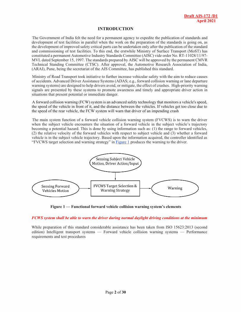
The main system function of a forward vehicle collision warning system (FVCWS) is to warn the driver
when the subject vehicle encounters the situation of a forward vehicle in the subject vehicle’s trajectory becoming a potential hazard. This is done by using information such as: (1) the range to forward vehicles, (2) the relative velocity of the forward vehicles with respect to subject vehicle and (3) whether a forward vehicle is in the subject vehicle trajectory. Based upon the information acquired, the controller identified as “FVCWS target selection and warning strategy” in Figure 1 produces the warning to the driver.
Figure 1 — Functional forward vehicle collision warning system’s elements
FCWS system shall be able to warn the driver during normal daylight driving conditions at the minimum
While preparation of this standard considerable assistance has been taken from ISO 15623:2013 (second edition) Intelligent transport systems — Forward vehicle collision warning systems — Performance requirements and test procedures
Draft AIS-172 /D1 April 2021
Page 3 of 30
Contents
Foreword
Introduction
1 Scope
2 Normative references
3 Terms and definitions
4 Symbols and abbreviated terms
5 Specifications and requirements
5.1 System functionality 5.2 Necessary functions 5.3 Operating model 5.4 Warning functionality 5.5 Warning elements requirements 5.6 System Classification 5.7 Obstacle vehicle detection area and performance 5.8 FVCWS performance on curves 5.9 User safety requirements 5.10 Human interface requirements 5.11 Awareness of system limitations
6 Evaluation test method for measuring detection performance 6.1 Test target specification 6.2 Environmental conditions 6.3 Test method for detection zone 6.4 Test method for warning distance range and accuracy 6.5 Test method for target discrimination ability
Annex A (informative) Basic consideration of collision warning
Annex B (informative) Obstacle detection along curves
Annex C (informative) Laser radar – Coefficient of test target
Annex D (informative) Radio wave radar test target geometry
Draft AIS-172 /D1 April 2021
Page 4 of 30
Intelligent transport systems - Forward vehicle collision warning systems - Performance requirements and test procedures
1 Scope
This Standard applies to the approval of vehicles of category M2, M3, N2 and N3 as defined in IS 14272: 2011 as amended from time to time with regard to systems capable of warning the driver of a potential rear-end in lane collision with other vehicles ahead of the subject vehicle while it is operating at ordinary speed.
This Standard covers operations on roads with curve radii over 500m and motor vehicle including cars, trucks and buses. Responsibility for the safe operation of the vehicle remains with the driver.
2 References
2.1 IS 14272: Automotive Vehicles –Types Terminology
2.2 AIS-004 (Part 3): Automotive Vehicles –Requirements for Electromagnetic Compatibility
3 Terms and definitions
For the purpose of this Standard the following terms and definitions apply.
3.1 Collision warning
Information that the system gives to the driver indicating the need for urgent action to avoid or reduce the severity of a potential rear end collision with another forward vehicle. This warning is issued in the advanced stages of a dangerous situation to warn the driver of the need to perform emergency braking, lane changing or other emergency manoeuvres in order necessary actions to avoid a collision.
3.2 Reflection coefficient of test target RCTT
Optical radar reflectivity of the target, which is defined as the radiated intensity towards the receiver (Iref - W/sr) measured at target level, immediately after the reflection; divided by the intensity of irradiation received from the transmitter (Et - W/m2) measured at target level, immediately before the reflection. The units for RCTT value are in m2/sr (see Annex C).
3.3 Forward vehicle
Vehicle in front of and moving in the same direction and travelling on the same roadway as the subject vehicle.
3.4 Forward vehicle collision warning system
FVCWS system capable of warning the driver of a potential collision with another forward vehicle in the forward path of the subject vehicle
3.5 Obstacle vehicles
Vehicles, both moving and stationary, considered potential hazards that can be detected by this system FVCWS.
Draft AIS-172 /D1 April 2021
Page 5 of 30
3.6 Preliminary collision warning
Information that the system gives to the driver in the early stages of a potentially dangerous situation that may result in a rear end collision. The system may provide this warning prior to the collision warning.
3.7 Radar cross section RCS
Measure of the reflective strength of a radar target measured in square meters, and defined as 4π times the ratio of the power per unit solid angle scattered in a specified direction to the power per unit area in a radio wave incident on the scatterer from a specified direction
3.8 Visibility
Distance which the illuminance of a non-diffusive beam of white light with the colour temperature of 2700 K is decreased to 5 % of its original light source illuminance.
3.9 (Reserved)
3.10 Adjacent lane
Lane of travel sharing one lane boundary with the lane in which the subject vehicle is traveling and having the same direction of travel as the subject vehicle lane.
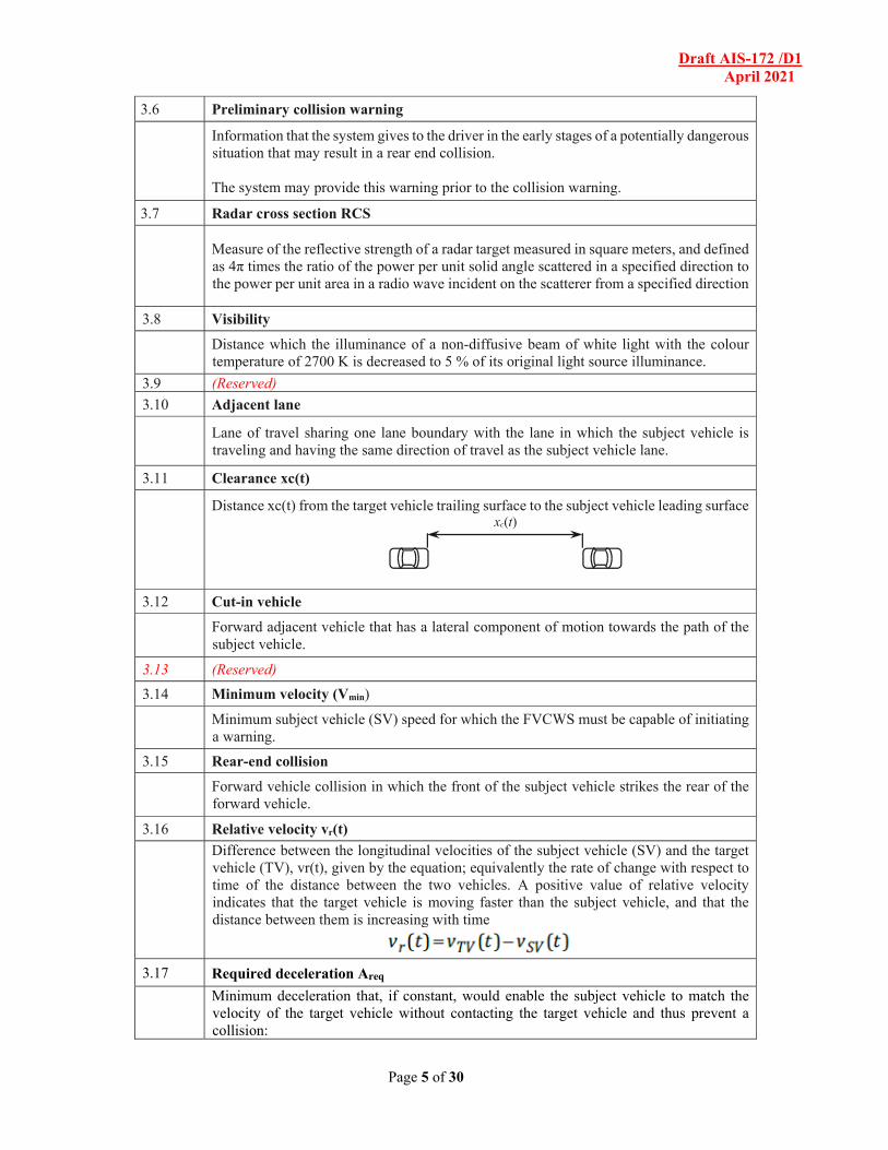
3.11 Clearance xc(t)
Distance xc(t) from the target vehicle trailing surface to the subject vehicle leading surface xc(t)
3.12 Cut-in vehicle
Forward adjacent vehicle that has a lateral component of motion towards the path of the subject vehicle.
3.13 (Reserved)
3.14 Minimum velocity (Vmin)
Minimum subject vehicle (SV) speed for which the FVCWS must be capable of initiating a warning.
3.15 Rear-end collision
Forward vehicle collision in which the front of the subject vehicle strikes the rear of the forward vehicle.
3.16 Relative velocity vr(t)
Difference between the longitudinal velocities of the subject vehicle (SV) and the target vehicle (TV), vr(t), given by the equation; equivalently the rate of change with respect to time of the distance between the two vehicles. A positive value of relative velocity indicates that the target vehicle is moving faster than the subject vehicle, and that the distance between them is increasing with time
3.17 Required deceleration Areq
Minimum deceleration that, if constant, would enable the subject vehicle to match the velocity of the target vehicle without contacting the target vehicle and thus prevent a collision:
Draft AIS-172 /D1 April 2021
Page 6 of 30
Note 1 to entry: xr(t) is the amount of reduction in the clearance distance due to reaction time.
3.18 Subject vehicle SV
Vehicle equipped with FVCWS as defined herein
3.19 Target vehicle TV
Forward vehicle that is closest in the forward path of the subject vehicle; forward vehicle that the FVCWS operates on.
3.20 Time to collision TTC
Estimated time that it will take a subject vehicle to collide with the target vehicle assuming the current relative speed remains constant, as given in the following equation:
3.21 Enhanced time to collision ETTC
time that it will take a subject vehicle to collide with the target vehicle assuming the relative acceleration between the subject vehicle (SV) and target vehicle (TV) remains constant, as given in the following equation:
3.22 (Reserved)
3.23 FVCWS warning modalities
Means used to convey the different type of FVCWS warnings to the driver. EXAMPLE: Visual, auditory, and/or haptic cues.
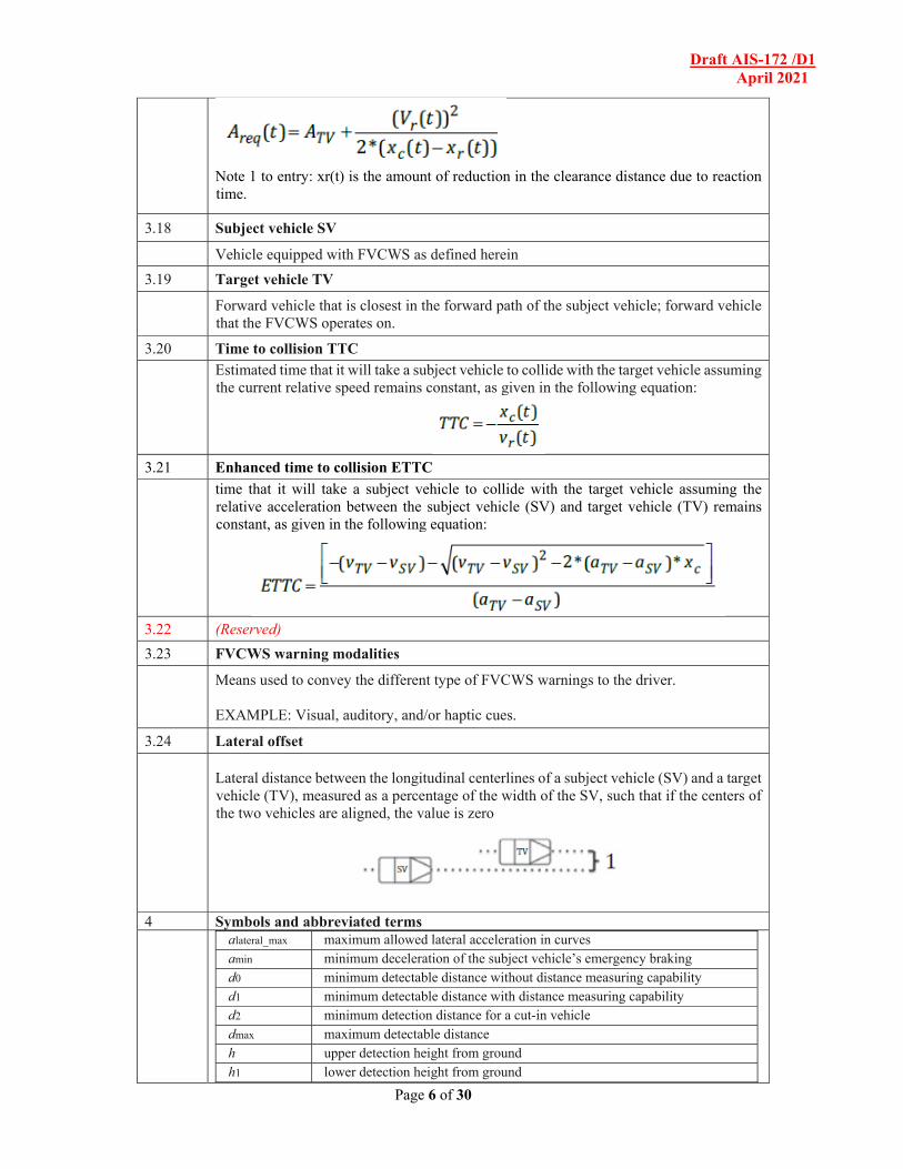
3.24 Lateral offset
Lateral distance between the longitudinal centerlines of a subject vehicle (SV) and a target vehicle (TV), measured as a percentage of the width of the SV, such that if the centers of the two vehicles are aligned, the value is zero
4 Symbols and abbreviated terms
alateral_max maximum allowed lateral acceleration in curves amin minimum deceleration of the subject vehicle’s emergency braking d0 minimum detectable distance without distance measuring capability d1 minimum detectable distance with distance measuring capability d2 minimum detection distance for a cut-in vehicle dmax maximum detectable distance h upper detection height from ground h1 lower detection height from ground
Draft AIS-172 /D1 April 2021
Page 7 of 30
RCTT reflection coefficient for test target for infrared reflector Tmax maximum driver’s brake reaction time after the warning Tmin minimum driver’s brake reaction time after the warning Tresp driver brake reaction time Tb braking system response time RCS radar cross section Vcircle_start speed of the test vehicles at the start of the test Vmax maximum vehicle speed at which the system is capable of operating Vmin minimum vehicle speed at which the system is capable of operating Vrel_max maximum relative vehicle speed at which the system is capable of operating WL lane width WV subject vehicle width
5 Specifications and requirements
5.1 System functionality
The purpose of the FVCWS is to provide warnings that will assist drivers in avoiding or reducing the severity of rear end crashes. These warnings should be provided in time to help drivers avoid most common rear end crashes by applying the brakes only. The timing of the alerts should be selected such that they strive to provide alerts early enough to help the driver avoid the crash or mitigate the harm caused by the crash without introducing other alerts perceived as nuisance or false. FVCWS provide warning only and do not perform vehicle control to mitigate the crash. FVCWS shall comply with EMC requirements as per AIS-004 (Part 3).
5.2 Necessary functions
Vehicles equipped with FVCWS shall be equipped to fulfil the following functions. - Detect the presence of forward vehicles, - Determine measure or measures for relative position and position dynamic of the
detected forward vehicles with respect to the subject vehicle, - Determine the subject vehicle velocity, - Provide driver warnings in accordance with the FVCWS function and requirements.
5.3 Operating model (Figure 2 below is only informative)
Draft AIS-172 /D1 April 2021
Page 8 of 30
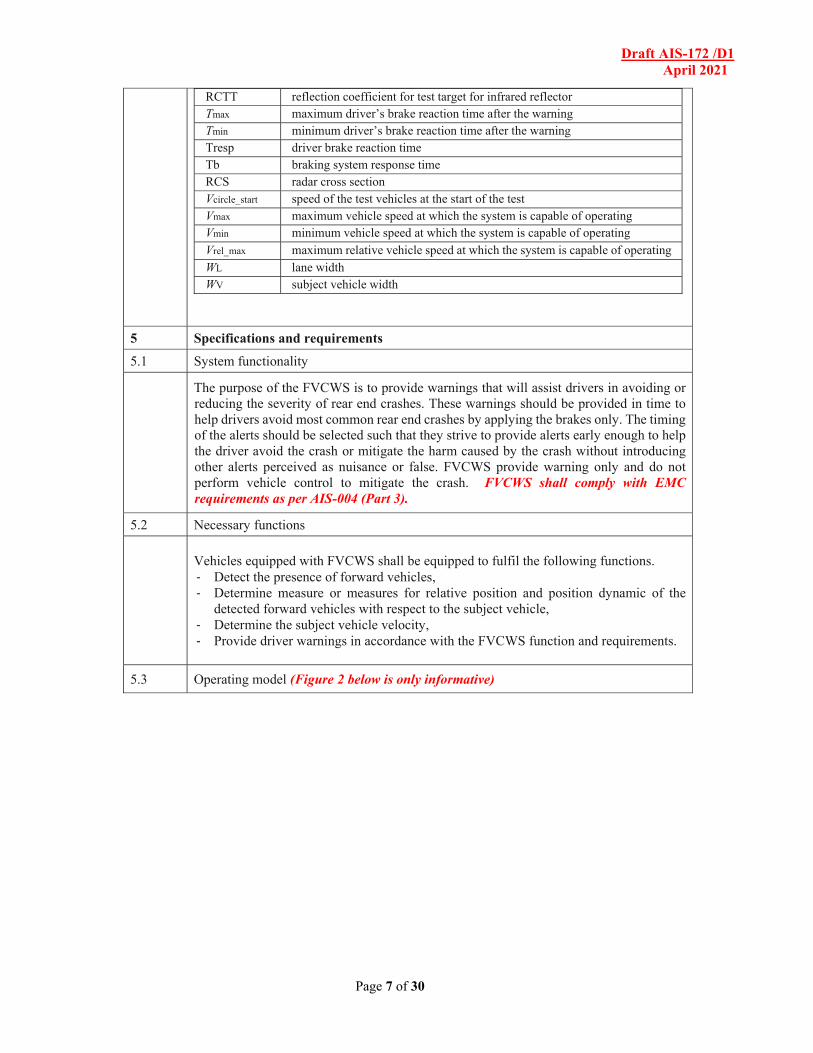
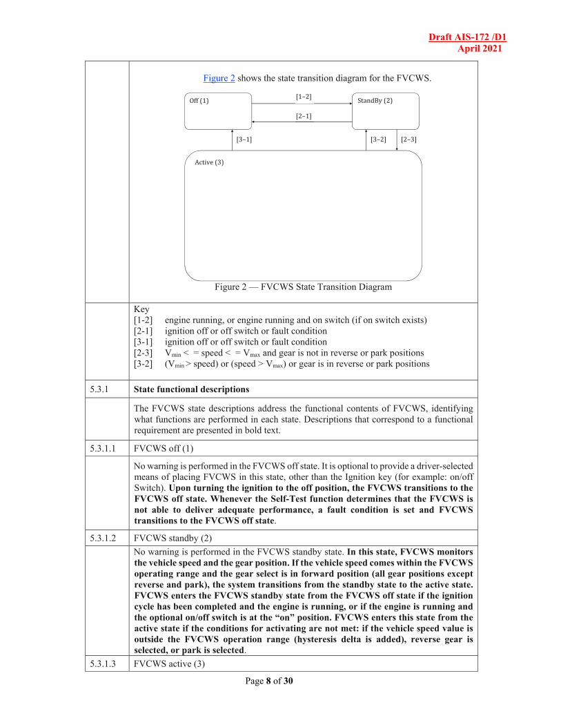
Figure 2 shows the state transition diagram for the FVCWS.
Figure 2 — FVCWS State Transition Diagram
Key [1-2] engine running, or engine running and on switch (if on switch exists) [2-1] ignition off or off switch or fault condition [3-1] ignition off or off switch or fault condition [2-3] Vmin < = speed < = Vmax and gear is not in reverse or park positions [3-2] (Vmin > speed) or (speed > Vmax) or gear is in reverse or park positions
5.3.1 State functional descriptions
The FVCWS state descriptions address the functional contents of FVCWS, identifying what functions are performed in each state. Descriptions that correspond to a functional requirement are presented in bold text.
5.3.1.1 FVCWS off (1)
No warning is performed in the FVCWS off state. It is optional to provide a driver-selected means of placing FVCWS in this state, other than the Ignition key (for example: on/off Switch). Upon turning the ignition to the off position, the FVCWS transitions to the FVCWS off state. Whenever the Self-Test function determines that the FVCWS is not able to deliver adequate performance, a fault condition is set and FVCWS transitions to the FVCWS off state.
5.3.1.2 FVCWS standby (2)
No warning is performed in the FVCWS standby state. In this state, FVCWS monitors the vehicle speed and the gear position. If the vehicle speed comes within the FVCWS operating range and the gear select is in forward position (all gear positions except reverse and park), the system transitions from the standby state to the active state. FVCWS enters the FVCWS standby state from the FVCWS off state if the ignition cycle has been completed and the engine is running, or if the engine is running and the optional on/off switch is at the “on” position. FVCWS enters this state from the active state if the conditions for activating are not met: if the vehicle speed value is outside the FVCWS operation range (hysteresis delta is added), reverse gear is selected, or park is selected.
5.3.1.3 FVCWS active (3)
Active (3)
Off (1) StandBy (2) [1 – 2]
[2 – 1]
[3 – 1] [3 – 2] [2 – 3]
Draft AIS-172 /D1 April 2021
Page 9 of 30
The warning is performed in this state whenever the warning conditions are met. FVCWS enters this state if gear select is in any forward position and the vehicle speed value is in the FVCWS operation range.
5.3.2 Operational limits
The value of Vmin shall be at most 15 km/h. The value of Vmax shall be at least the minimum of 80 km/h and the maximum vehicle operating speed.
5.4 Warning functionality
Forward vehicle collision warning systems shall provide warnings for moving (including “has been detected as moving by the sensor and now stopped”) obstacle vehicles. Providing warnings for stationary obstacle vehicles (has never been detected moving at an absolute speed above 4,2 m/s) is optional. The FVCWS warning is provided in accordance with the following functions.
5.4.1 Monitoring distance and relative speed between obstacle vehicle and subject vehicle.
A forward obstacle vehicle is sensed by obstacle detecting devices such as optical (laser) radar, radio wave radar, or image processing systems or any other device or systems.
5.4.2 Judging the timing of collision
One possible way to judge the timing of a potential collision is by the results of evaluating the subject vehicle speed, the distance to the obstacle vehicle, the relative speed between the subject vehicle and the obstacle vehicle, and potentially the deceleration of the subject and the obstacle vehicles. When the system detects multiple vehicles at the same time, it shall select the one in the subject vehicle expected trajectory that the subject vehicle may collide with first if no action is taken as the obstacle vehicle.
5.4.3 Preliminary collision warning and Collision warning (see Annex A)
Forward vehicle collision warning systems shall provide a collision warning to the driver. A preliminary collision warning is optional. The purpose of the preliminary collision warning is to inform the driver of the presence of a potential forward collision hazard. In this case the driver should prepare to take the necessary action to avoid a potential rear end collision. Even though the system is intended to provide this warning prior to the collision warning, it is possible that rapidly changing conditions can occur which result in the collision warning being issued without a preceding preliminary collision warning. The purpose of the collision warning is to inform the driver of the need to take action in order to avoid or reduce the severity of a possible imminent rear end collision. Warnings consist of independent or combined use of visual, audible and/or tactile senses. However, in the case of a collision warning, a visual warning, as well as audible warning shall be provided to the driver.
Warnings are issued depending on the relative speed between the subject vehicle and the obstacle vehicle, the subject vehicle speed, the inter-vehicle distance, the free running (driver’s brake reaction) time, and potentially the deceleration of the subject and the obstacle vehicles.
When the subject vehicle is approaching an obstacle vehicle, the warning distance should be decided according to criteria with respect to required deceleration threshold values or their equivalents if other warning triggering methods are used.
5.5 Warning elements requirements
5.5.1 FVCWS output
Draft AIS-172 /D1 April 2021
Page 10 of 30
FVCWS shall provide a collision warning to the driver. A preliminary collision warning is optional.
5.5.2 Warning modality
5.5.2.1 FVCWS collision warning shall contain a visual warning, as well as an audible.
5.5.2.2 FVCWS preliminary collision warning shall contain visual or audible or a combination of visual and audible modalities. Supplemental haptic modalities are optional for preliminary collision warning.
5.5.2.3 to
5.5.2.5 (Reserved)
5.5.2.6 Audible warning tone should be selected such that it can be easily heard and discriminated from warnings unrelated to forward direction threats (e.g. lateral threat warnings).
5.5.2.7 An actuation of seat-belt pre-tensioner may be used for FVCWS collision warning.
5.5.3 Required deceleration threshold
5.5.3.1 FVCWS shall issue a collision warning when the required deceleration exceeds a threshold value of Areq. The threshold value Areq shall not be greater than 6.67 m/s2 (considering the response time values in 5.5.4) in dry road and warm weather conditions
5.5.3.2 FVCWS that provide a warning timing adjustment for the driver must have at least one setting that satisfies the required deceleration threshold value Areq requirement in 5.5.3.1.
5.5.3.3 FVCWS may issue a preliminary collision warning at a lower required deceleration threshold.
5.5.3.4 The required deceleration threshold for collision and preliminary warnings may be adapted based on the detected road condition, environmental and driver state conditions, driver behavior and different driving scenarios.
5.5.4 Response times
5.5.4.1 The driver reaction time to the warning (driver brake reaction time (Tresp)) shall be incorporated in the calculation of the warning range. The Tresp value shall not be less than 0.8 s.
5.5.4.2 FVCWS that provide a warning timing adjustment for the driver must have a least one setting that satisfies the Tresp requirement in 5.5.4.1.
5.5.4.3 The braking system response time (Tb) may be incorporated in the calculation of the required deceleration. The selection of the braking system response time value is left to the FVCWS designer.
5.5.4.4 The driver brake reaction time (Tresp) and the braking system response time (Tb) may be set to zero if the subject vehicle driver is applying the brakes.
5.5.5 No Warning requirements
Sub-clause 5.5.5.1 states the condition when the FVCWS must not issue any type of warnings. Sub-clauses 5.5.5.2 5.5.5.4 to 5.5.5.7 provide examples when the FVCWS warning may be suppressed or delayed.
5.5.5.1 The FVCWS shall not issue any type of warnings if the subject vehicle deceleration is greater than or equal to the required deceleration threshold.
Draft AIS-172 /D1 April 2021
Page 11 of 30
5.5.5.2 The FVCWS should not issue any type of warnings for a forward vehicle that is not in the lane of the subject vehicle on roads with radius of curvature > 500 m.
5.5.5.3 It is recommended that the FVCWS does not issue any type of warnings for a faster forward vehicle that cuts in front of the subject vehicle.
5.5.5.4 The FVCWS warning may be suppressed or delayed if the subject vehicle driver is applying the brakes.
5.5.5.5 The FVCWS warning may be suppressed or delayed if the TTC is greater than 4,0 s.
5.5.5.6 The FVCWS warning may be suppressed or delayed if the subject vehicle is detected to be performing a lane change or high dynamic maneuvering,
5.5.5.7 The FVCWS warning may be suppressed or delayed if the situation is beyond the operational limits as defined in 5.3.2.
5.5.6
Warning distance range calculation example The calculation of the minimum required distance can be performed based on the Tresp =
0.8 s and Areq = 6.67 m/s2. Using the definition of Areq in 3.17,
5.5.7 Equivalent warning triggering point For other systems that use different warning triggering methods (e.g. TTC or ETTC), the warning triggering time shall meet the requirements 5.5.3, 5.5.4 and 5.5.5.
5.7 Obstacle vehicle detection area and performance
5.7.1 Obstacle vehicle detection area
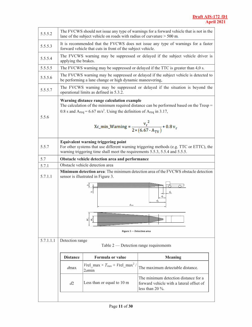
5.7.1.1
Minimum detection area: The minimum detection area of the FVCWS obstacle detection sensor is illustrated in Figure 3.
5.7.1.1.1
Detection range Table 2 — Detection range requirements
Distance Formula or value Meaning
dmax Vrel_max × Tmax + Vrel_max2 / 2amin
The maximum detectable distance.
d2 Less than or equal to 10 m The minimum detection distance for a forward vehicle with a lateral offset of less than 20 %.
Draft AIS-172 /D1 April 2021
Page 12 of 30
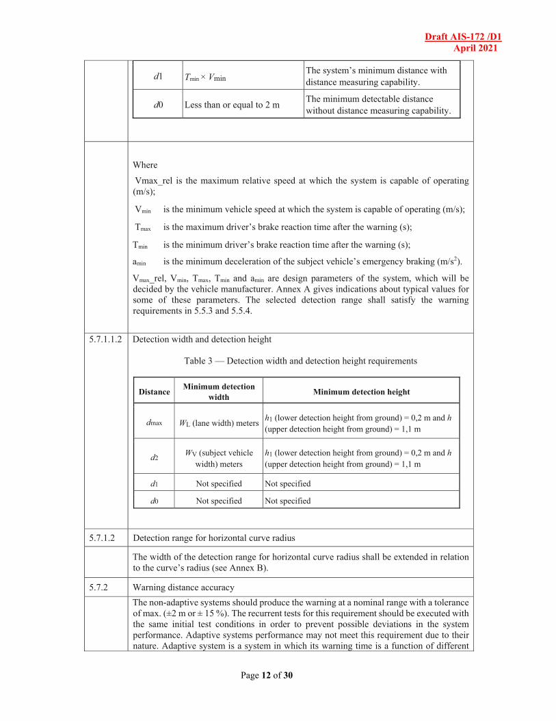
d1 Tmin × Vmin The system’s minimum distance with distance measuring capability.
d0 Less than or equal to 2 m The minimum detectable distance without distance measuring capability.
Where
Vmax_rel is the maximum relative speed at which the system is capable of operating (m/s);
Vmin is the minimum vehicle speed at which the system is capable of operating (m/s);
Tmax is the maximum driver’s brake reaction time after the warning (s);
Tmin is the minimum driver’s brake reaction time after the warning (s);
amin is the minimum deceleration of the subject vehicle’s emergency braking (m/s2).
Vmax_rel, Vmin, Tmax, Tmin and amin are design parameters of the system, which will be decided by the vehicle manufacturer. Annex A gives indications about typical values for some of these parameters. The selected detection range shall satisfy the warning requirements in 5.5.3 and 5.5.4.
5.7.1.1.2
Detection width and detection height
Table 3 — Detection width and detection height requirements
Distance Minimum detection
width Minimum detection height
dmax WL (lane width) meters h1 (lower detection height from ground) = 0,2 m and h (upper detection height from ground) = 1,1 m
d2 WV (subject vehicle width) meters
h1 (lower detection height from ground) = 0,2 m and h (upper detection height from ground) = 1,1 m
d1 Not specified Not specified
d0 Not specified Not specified
5.7.1.2 Detection range for horizontal curve radius
The width of the detection range for horizontal curve radius shall be extended in relation to the curve’s radius (see Annex B).
5.7.2 Warning distance accuracy
The non-adaptive systems should produce the warning at a nominal range with a tolerance of max. (±2 m or ± 15 %). The recurrent tests for this requirement should be executed with the same initial test conditions in order to prevent possible deviations in the system performance. Adaptive systems performance may not meet this requirement due to their nature. Adaptive system is a system in which its warning time is a function of different
Draft AIS-172 /D1 April 2021
Page 13 of 30
parameters, for example the detected road condition, environmental and driver state conditions, driver behavior and different driving scenarios.
5.7.3 Target discrimination ability
5.7.3.1 Longitudinal discrimination
If there are two or more forward vehicles in the detection range from a distance d1 to dmax from the subject vehicle’s front end, the system shall select the vehicle that is closest to the subject vehicle and in the subject vehicle’s trajectory as the target vehicle that the FVCWS will operate on.
5.7.3.2 Lateral discrimination
If there are two or more forward vehicles in the subject vehicle’s trajectory or in an adjacent position, the system shall select the vehicle in the subject vehicle’s trajectory as the target vehicle that the FVCWS will operate on.
5.7.3.3 Overhead discrimination
If there are overhead objects at a height greater than 4.75 m above the roadway such as overhead sign, etc., the system shall not select any of these objects as the target vehicle.
5.8 FVCWS performance on curves
FVCWS shall be able to warn on in-path obstacle vehicles that exist in straight roads and curves with radius of curvature greater than or equal to 500 m.
5.9 User safety requirements
5.9.1 Optical radar shall satisfy the requirements for Class I lasers as defined in IEC 825-1 or equivalent Indian/ International standards.
5.10 Human interface requirements
5.10.1 Warning output specification
All visual, audible, and / or haptic warnings shall be perceptible by the driver. It is recommended that the visual and audible warning satisfy appropriate human factors as shown in Table 4. The content in Table 4 is an example. The warning modality requirements for both collision and preliminary warnings are shown in 5.5.2.
Draft AIS-172 /D1 April 2021
Page 14 of 30
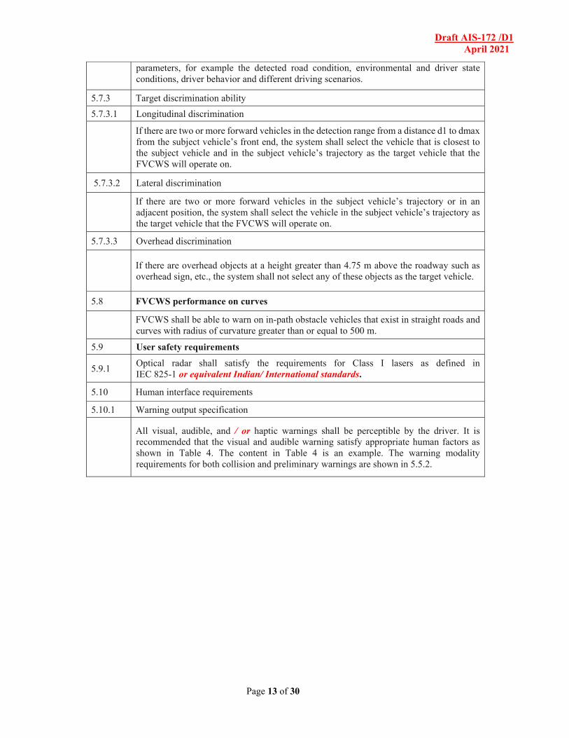
Table 4 — Warning characteristics
Warning Visual warning Auditory warning
Collision warning
Colour: Red Position: Main glance direction Luminance: Luminance enough in day light, not glaring in the night. Interval: Intermittent at short interval is recommended
Pressure: Sound pressure should be at the same level or higher of those of all auditory warnings present in the vehicle conveying more urgency than other auditory warnings. Tone: Can be easily heard and discriminated from any other unrelated warnings in the vehicle. Interval: Intermittent at short interval is recommended
Preliminary collision warning
Colour: yellow or amber Luminance: Luminous enough in daylight, not glaring in the night. Interval: Continuous or intermittent at long interval.
Pressure: Sound pressure overriding background noise. Tone: Not annoying tone Interval: Continuous sound or intermittent at long interval or single sound
5.10.2 Interference with other warnings
Even when a vehicle is equipped with a forward vehicle collision warning system along with other warning systems such as those for rear or side obstacles, the warning should be clearly distinguishable to the driver relative to other unrelated warnings.
5.10.3 Operational status display
Indications such as those below, which clearly identify the system’s operational status shall be provided.
5.10.3.1 System in-operation indication
An indication which informs the driver that the system is operational may be provided (e.g. an illuminated power switch).
5.10.3.2 Fault indication
An indication which informs the driver of a system failure shall be provided (e.g. a fault indication on the display panel).
5.11 Awareness of system limitations
System users should be made aware of the system limitations as follows using appropriate means such as owner’s manual and/or caution label. For example, warnings for head-on collision, crossing-path collision, operations beyond the sensor limit (including short radius curve, etc.), and the maximum velocity (Vmax) has been reached are not available with this system.
6 Evaluation test method for measuring detection performance
6.1 Test target specification
6.1.1 Optical radar
The test target is defined as possessing the physical size, shape, and surface profile of a representative passenger car and with a reflection coefficient for test target (RCTT) which represents the reflectivity of passenger car.
6.1.2 Radio wave radar
Draft AIS-172 /D1 April 2021
Page 15 of 30
The test target is defined by a radar cross section (RCS) that is representative of passenger car. NOTE: In actual use, the measurement range of automotive obstacle vehicle detection sensors is comparatively short, it is difficult to achieve a plane wave on the scatterer. Therefore, RCS values for the automotive use are defined by measured values in the actual using range for the sake of convenience. Examples of possible test target geometry are discussed in the Annex D.
6.1.3 Passive optical sensor
The test target is defined as possessing the physical size, shape, and surface profile of a representative passenger vehicle car.
6.2
Environmental conditions — Test location shall be on a flat, dry asphalt or concrete surface. — Temperature range shall be −20 °C to 40 °C or as declared by manufacturer based on Indian conditions. — Horizontal visibility shall be greater than 1 km. — Test may occur during daylight conditions.
6.3 Test method for detection zone
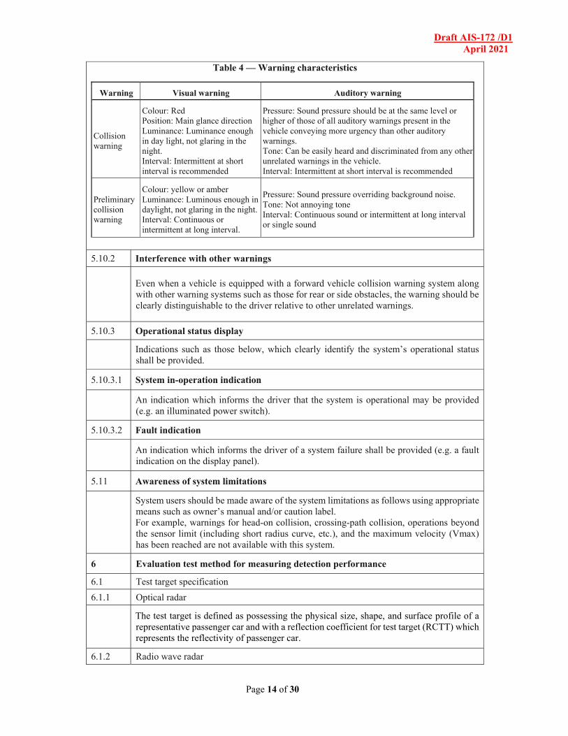
The most realistic test for detection area is a dynamic test, however, a static test is available as an option also. The test shall be done as follows. The system shall detect a test target positioned at an arbitrary distance between d0 and d1 as shown in Figure 4.
The system shall detect a test target positioned at an arbitrary distance between d1 and d2 as shown in Figure 4. The system shall detect test targets positioned in turn at both distance d2 and dmax as shown in Figure 4.
Figure 4 — Detection range
If detection cannot be validated without special measurement equipment, such as when a sensor and ECU are tightly integrated, the manufacturer may conduct this test using special measurement equipment and provide test results for inspection. Additionally, as this test allows for a dynamic test, it may be conducted simultaneously with another test in Clause 6 such that the intent of this test method is fulfilled in the execution of another test. For example, a test vehicle meeting the previously defined test target specifications may be used as a test target. Successful initiation of a collision warning at the various distances defined in this test may be considered successful detection.
6.4 Test method for warning distance range and accuracy
6.4.1 Warning distance range test
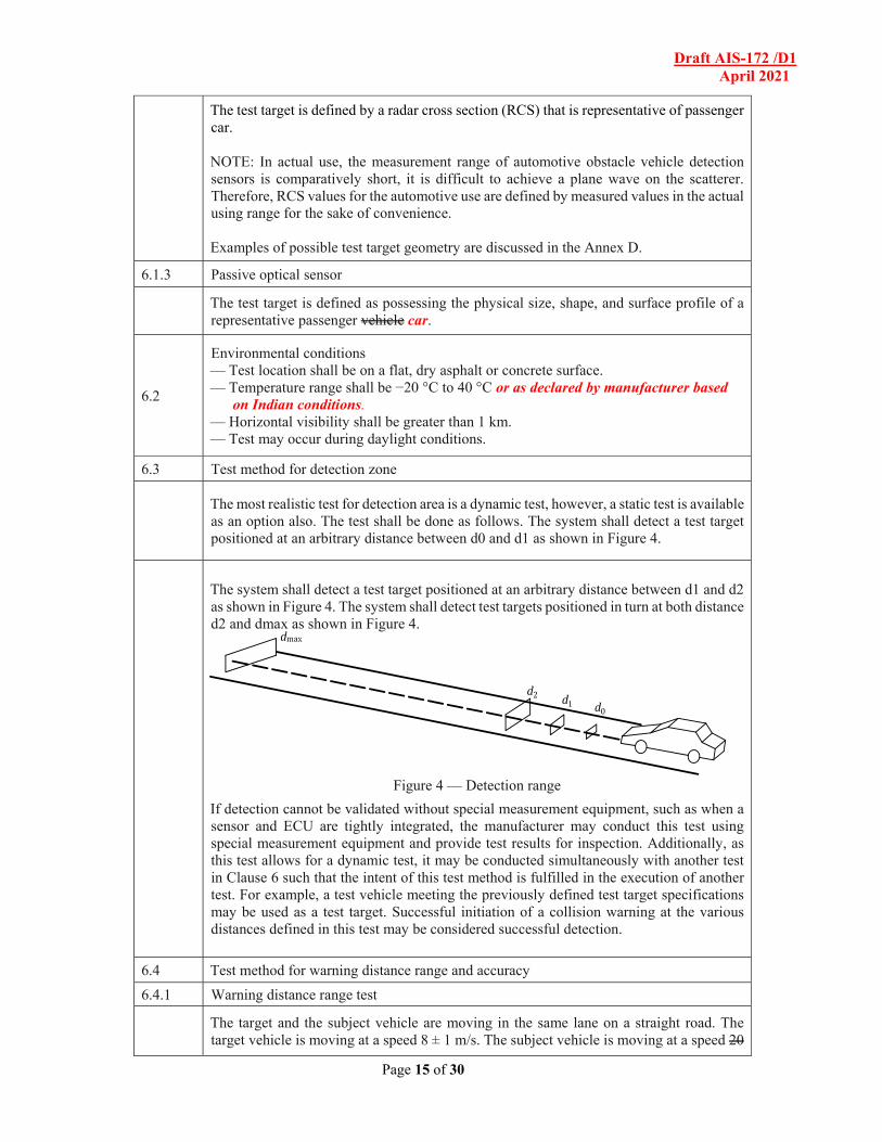
The target and the subject vehicle are moving in the same lane on a straight road. The target vehicle is moving at a speed 8 ± 1 m/s. The subject vehicle is moving at a speed 20
Draft AIS-172 /D1 April 2021
Page 16 of 30
± 2 m/s which is equivalent to 80% of maximum vehicle operating speed. The measured warning distance shall be greater than or equal to distance calculated in 5.5.6.
Figure 5 — Warning distance range test
Key 1 SV traveling at 20 ± 2 m/s 80% of maximum vehicle operating speed
2 TV traveling at 8 ± 1 m/s
6.4.2 Warning distance accuracy test
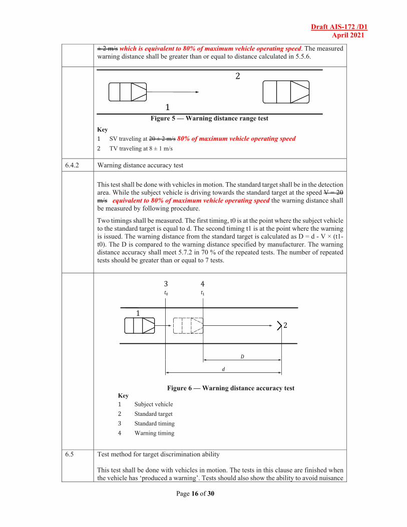
This test shall be done with vehicles in motion. The standard target shall be in the detection area. While the subject vehicle is driving towards the standard target at the speed V = 20 m/s equivalent to 80% of maximum vehicle operating speed the warning distance shall be measured by following procedure.
Two timings shall be measured. The first timing, t0 is at the point where the subject vehicle to the standard target is equal to d. The second timing t1 is at the point where the warning is issued. The warning distance from the standard target is calculated as D = d - V × (t1-t0). The D is compared to the warning distance specified by manufacturer. The warning distance accuracy shall meet 5.7.2 in 70 % of the repeated tests. The number of repeated tests should be greater than or equal to 7 tests.
6.5 Test method for target discrimination ability This test shall be done with vehicles in motion. The tests in this clause are finished when the vehicle has ‘produced a warning’. Tests should also show the ability to avoid nuisance
Draft AIS-172 /D1 April 2021
Page 17 of 30
warnings. For example, test conditions which are finished when the maneuver is complete, and no warning has been produced.
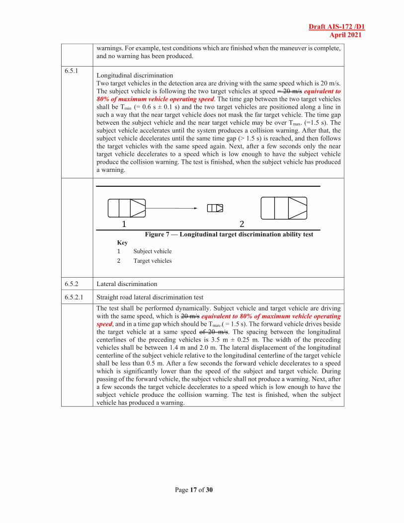
6.5.1 Longitudinal discrimination Two target vehicles in the detection area are driving with the same speed which is 20 m/s. The subject vehicle is following the two target vehicles at speed = 20 m/s equivalent to 80% of maximum vehicle operating speed. The time gap between the two target vehicles shall be Tmin (= 0.6 s ± 0.1 s) and the two target vehicles are positioned along a line in such a way that the near target vehicle does not mask the far target vehicle. The time gap between the subject vehicle and the near target vehicle may be over Tmax. (=1.5 s). The subject vehicle accelerates until the system produces a collision warning. After that, the subject vehicle decelerates until the same time gap (> 1.5 s) is reached, and then follows the target vehicles with the same speed again. Next, after a few seconds only the near target vehicle decelerates to a speed which is low enough to have the subject vehicle produce the collision warning. The test is finished, when the subject vehicle has produced a warning.
Figure 7 — Longitudinal target discrimination ability test
Key 1 Subject vehicle
2 Target vehicles
6.5.2 Lateral discrimination
6.5.2.1 Straight road lateral discrimination test
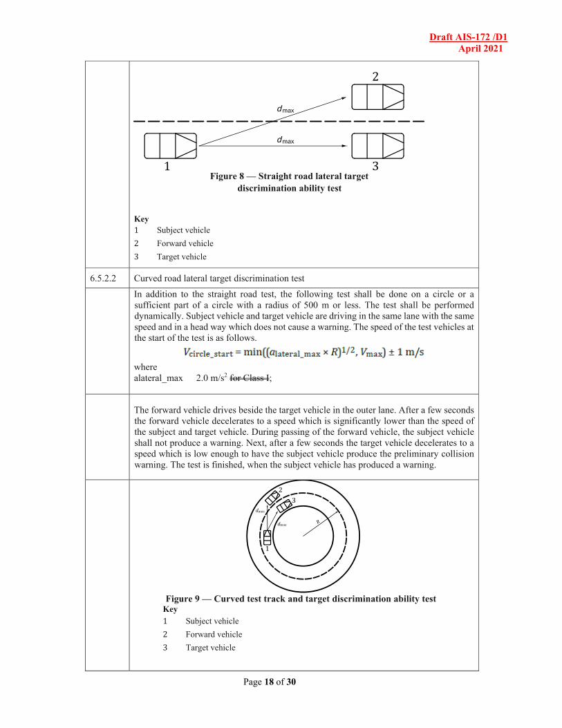
The test shall be performed dynamically. Subject vehicle and target vehicle are driving with the same speed, which is 20 m/s equivalent to 80% of maximum vehicle operating speed, and in a time gap which should be Tmax.( = 1.5 s). The forward vehicle drives beside the target vehicle at a same speed of 20 m/s. The spacing between the longitudinal centerlines of the preceding vehicles is 3.5 m ± 0.25 m. The width of the preceding vehicles shall be between 1.4 m and 2.0 m. The lateral displacement of the longitudinal centerline of the subject vehicle relative to the longitudinal centerline of the target vehicle shall be less than 0.5 m. After a few seconds the forward vehicle decelerates to a speed which is significantly lower than the speed of the subject and target vehicle. During passing of the forward vehicle, the subject vehicle shall not produce a warning. Next, after a few seconds the target vehicle decelerates to a speed which is low enough to have the subject vehicle produce the collision warning. The test is finished, when the subject vehicle has produced a warning.
Draft AIS-172 /D1 April 2021
Page 18 of 30
Figure 8 — Straight road lateral target
discrimination ability test
Key 1 Subject vehicle
2 Forward vehicle
3 Target vehicle
6.5.2.2 Curved road lateral target discrimination test
In addition to the straight road test, the following test shall be done on a circle or a sufficient part of a circle with a radius of 500 m or less. The test shall be performed dynamically. Subject vehicle and target vehicle are driving in the same lane with the same speed and in a head way which does not cause a warning. The speed of the test vehicles at the start of the test is as follows.
where alateral_max 2.0 m/s2 for Class I;
The forward vehicle drives beside the target vehicle in the outer lane. After a few seconds the forward vehicle decelerates to a speed which is significantly lower than the speed of the subject and target vehicle. During passing of the forward vehicle, the subject vehicle shall not produce a warning. Next, after a few seconds the target vehicle decelerates to a speed which is low enough to have the subject vehicle produce the preliminary collision warning. The test is finished, when the subject vehicle has produced a warning.
Figure 9 — Curved test track and target discrimination ability test
Key 1 Subject vehicle
2 Forward vehicle
3 Target vehicle
Draft AIS-172 /D1 April 2021
Page 19 of 30
6.5.3 Overhead discrimination
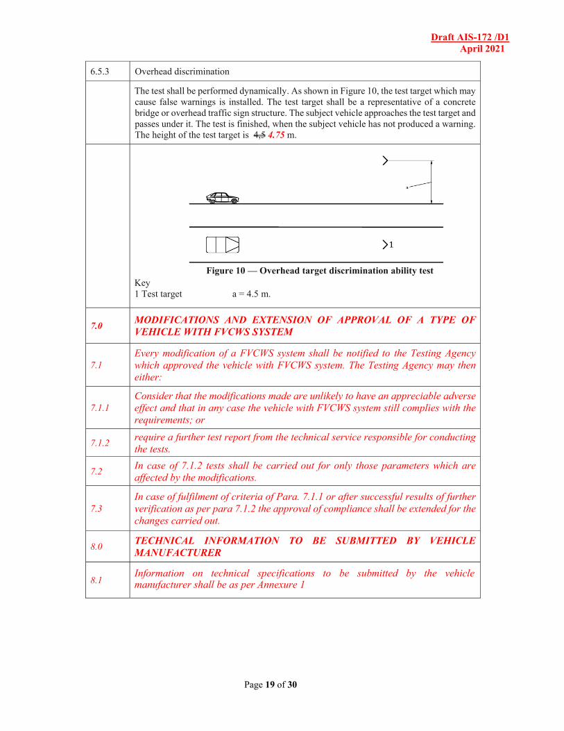
The test shall be performed dynamically. As shown in Figure 10, the test target which may cause false warnings is installed. The test target shall be a representative of a concrete bridge or overhead traffic sign structure. The subject vehicle approaches the test target and passes under it. The test is finished, when the subject vehicle has not produced a warning. The height of the test target is 4,5 4.75 m.
Figure 10 — Overhead target discrimination ability test
Key 1 Test target a = 4.5 m.
7.0 MODIFICATIONS AND EXTENSION OF APPROVAL OF A TYPE OF VEHICLE WITH FVCWS SYSTEM
7.1 Every modification of a FVCWS system shall be notified to the Testing Agency which approved the vehicle with FVCWS system. The Testing Agency may then either:
7.1.1 Consider that the modifications made are unlikely to have an appreciable adverse effect and that in any case the vehicle with FVCWS system still complies with the requirements; or
7.1.2 require a further test report from the technical service responsible for conducting the tests.
7.2 In case of 7.1.2 tests shall be carried out for only those parameters which are affected by the modifications.
7.3 In case of fulfilment of criteria of Para. 7.1.1 or after successful results of further verification as per para 7.1.2 the approval of compliance shall be extended for the changes carried out.
8.0 TECHNICAL INFORMATION TO BE SUBMITTED BY VEHICLE MANUFACTURER
8.1 Information on technical specifications to be submitted by the vehicle manufacturer shall be as per Annexure 1
Draft AIS-172 /D1 April 2021
Page 20 of 30
Annex A
(informative)
Basic consideration of collision warning
A.1 Basic equation
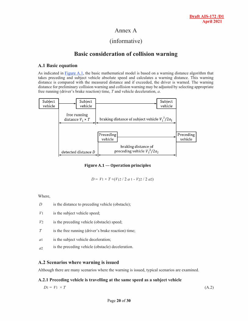
As indicated in Figure A.1, the basic mathematical model is based on a warning distance algorithm that takes preceding and subject vehicle absolute speed and calculates a warning distance. This warning distance is compared with the measured distance and if exceeded, the driver is warned. The warning distance for preliminary collision warning and collision warning may be adjusted by selecting appropriate free running (driver’s brake reaction) time, T and vehicle deceleration, a.
D = V1 × T +(V12 / 2 a 1 - V22 / 2 a2)
Where,
D is the distance to preceding vehicle (obstacle);
V1 is the subject vehicle speed;
V2 is the preceding vehicle (obstacle) speed;
T is the free running (driver’s brake reaction) time;
a1 is the subject vehicle deceleration;
a2 is the preceding vehicle (obstacle) deceleration.
A.2 Scenarios where warning is issued
Although there are many scenarios where the warning is issued, typical scenarios are examined.
A.2.1 Preceding vehicle is travelling at the same speed as a subject vehicle
D1 = V1 × T (A.2)
Draft AIS-172 /D1 April 2021
Page 21 of 30
A.2.2 Preceding vehicle is a stationary obstacle
D2 = V1 × T + V12 / 2a1 (A.3)
When the subject vehicle is approaching to the preceding vehicle travelling at a constant, V1 means the relative speed between the subject vehicle and the preceding vehicle.
A.2.3 Preceding vehicle is decelerating with relative speed, VRel = (V1 − V2)
D = (T + Vrel / a) × V1 - VRel2 / 2a (A.4)
A.3 Evaluation results of T and a
A.3.1 Free running (driver’s brake reaction) time, T
Values for T were based on the reference report.[1]
[1] “Johansson G., & Rumar K Driver’s Brake Reaction Times”. Hum. Factors. 1971, 13 (1) pp. 23–27”
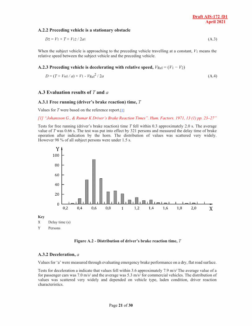
Tests for free running (driver’s brake reaction) time T fell within 0.3 approximately 2.0 s. The average value of T was 0.66 s. The test was put into effect by 321 persons and measured the delay time of brake operation after indication by the horn. The distribution of values was scattered very widely. However 98 % of all subject persons were under 1.5 s.
Key X Delay time (s)
Y Persons
Figure A.2 - Distribution of driver’s brake reaction time, T
A.3.2 Deceleration, a
Values for ‘a’ were measured through evaluating emergency brake performance on a dry, flat road surface.
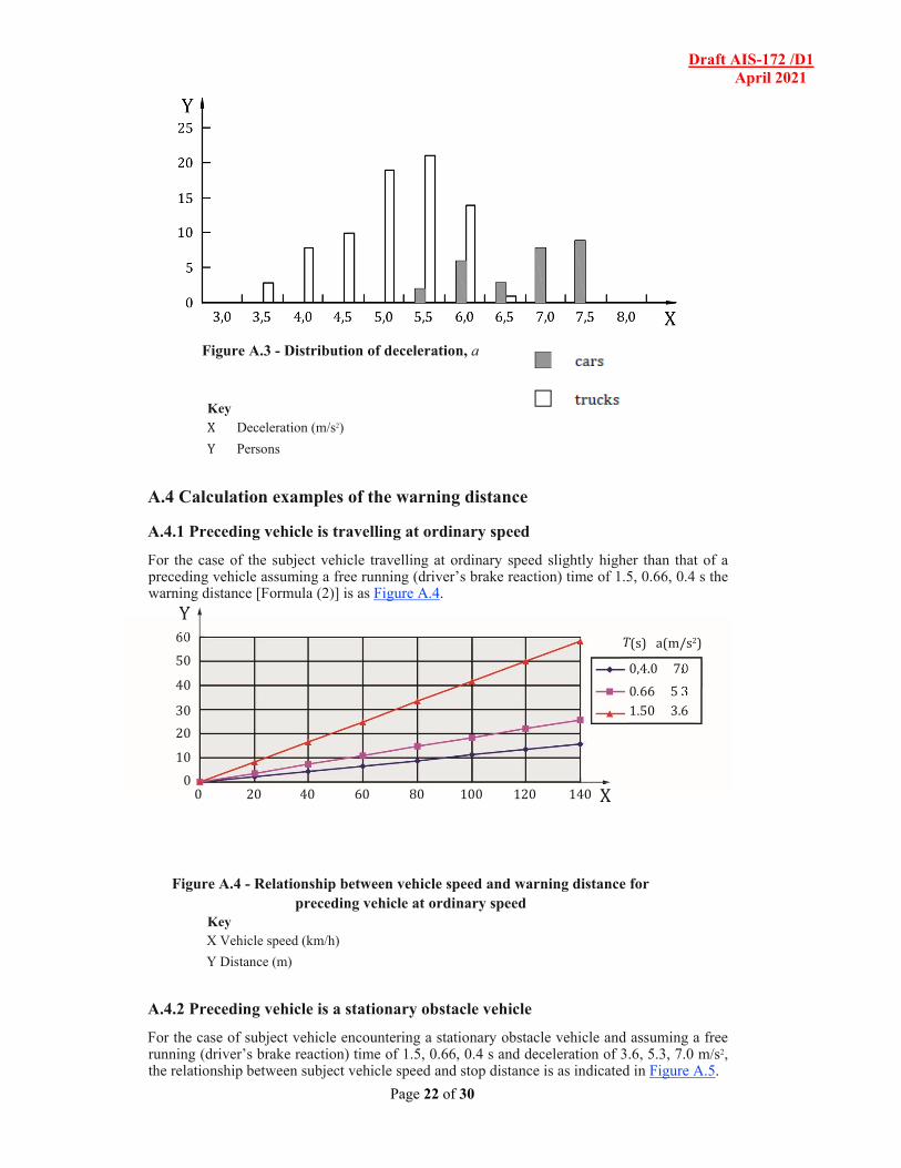
Tests for deceleration a indicate that values fell within 3.6 approximately 7.9 m/s2 The average value of a for passenger cars was 7.0 m/s2 and the average was 5.3 m/s2 for commercial vehicles. The distribution of values was scattered very widely and depended on vehicle type, laden condition, driver reaction characteristics.
Draft AIS-172 /D1 April 2021
Page 22 of 30
Figure A.3 - Distribution of deceleration, a
Key X Deceleration (m/s2)
Y Persons
A.4 Calculation examples of the warning distance
A.4.1 Preceding vehicle is travelling at ordinary speed
For the case of the subject vehicle travelling at ordinary speed slightly higher than that of a preceding vehicle assuming a free running (driver’s brake reaction) time of 1.5, 0.66, 0.4 s the warning distance [Formula (2)] is as Figure A.4.
Figure A.4 - Relationship between vehicle speed and warning distance for preceding vehicle at ordinary speed
Key X Vehicle speed (km/h) Y Distance (m)
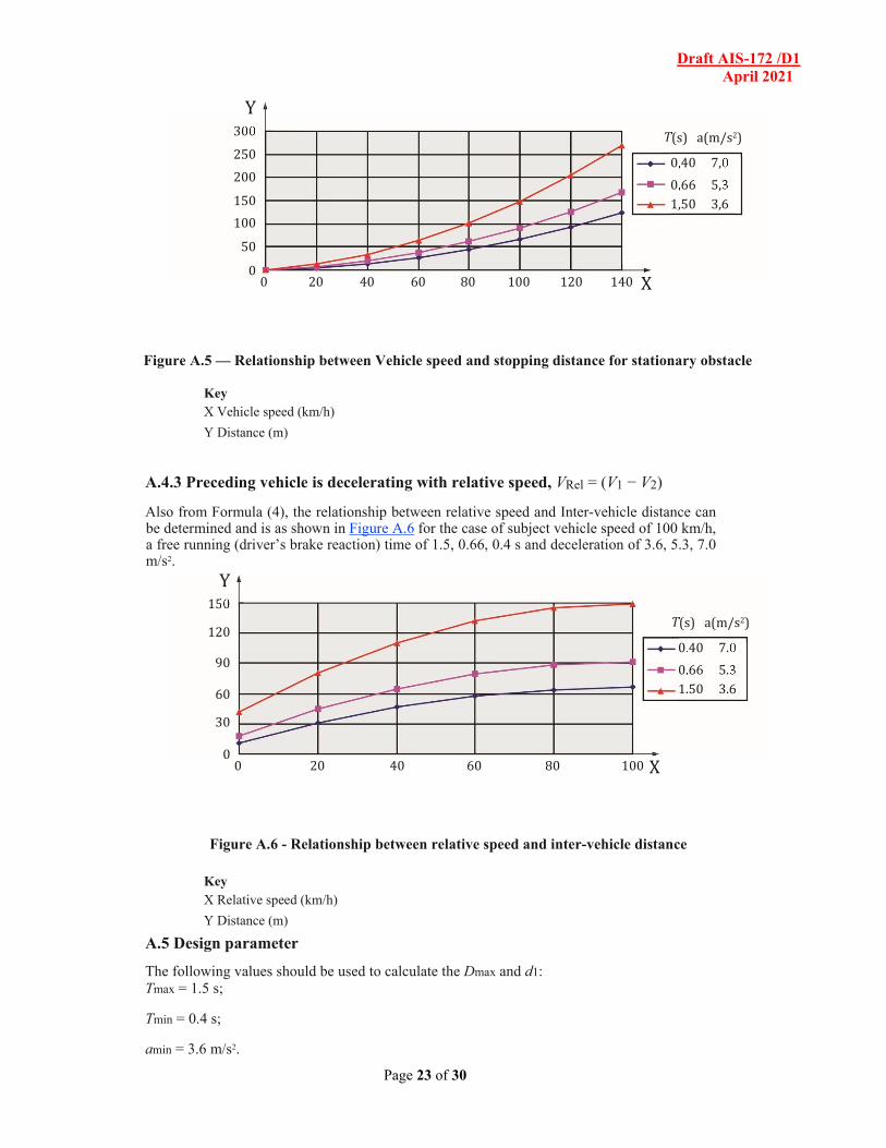
A.4.2 Preceding vehicle is a stationary obstacle vehicle
For the case of subject vehicle encountering a stationary obstacle vehicle and assuming a free running (driver’s brake reaction) time of 1.5, 0.66, 0.4 s and deceleration of 3.6, 5.3, 7.0 m/s2, the relationship between subject vehicle speed and stop distance is as indicated in Figure A.5.
60
50
40
30
20
10
0 0 20 40 60 80 100 120 140
0 ,4.0 7. 0
3 .66 5 0 1 .50 3. 6
T ( s) a(m/s 2 )
Y
X
Draft AIS-172 /D1 April 2021
Page 23 of 30
Figure A.5 — Relationship between Vehicle speed and stopping distance for stationary obstacle
Key X Vehicle speed (km/h)
Y Distance (m)
A.4.3 Preceding vehicle is decelerating with relative speed, VRel = (V1 − V2)
Also from Formula (4), the relationship between relative speed and Inter-vehicle distance can be determined and is as shown in Figure A.6 for the case of subject vehicle speed of 100 km/h, a free running (driver’s brake reaction) time of 1.5, 0.66, 0.4 s and deceleration of 3.6, 5.3, 7.0 m/s2.
Figure A.6 - Relationship between relative speed and inter-vehicle distance Key X Relative speed (km/h) Y Distance (m)
A.5 Design parameter
The following values should be used to calculate the Dmax and d1: Tmax = 1.5 s;
Tmin = 0.4 s;
amin = 3.6 m/s2.
300
250
200
150
100
50
0 0 20 40 60 80 100 120 140
0 ,40 7, 0
3 ,66 5, 0 1 ,50 3, 6
T ( s) a(m/s 2 )
Y
X
150
120
90
60
30
0 0 20 40 60 80 100
0 .40 7. 0
3 .66 5. 0 1 .50 3. 6
T ( s) a(m/s 2 )
Y
X
Draft AIS-172 /D1 April 2021
Page 24 of 30
Annex B (informative)
Obstacle detection along curves
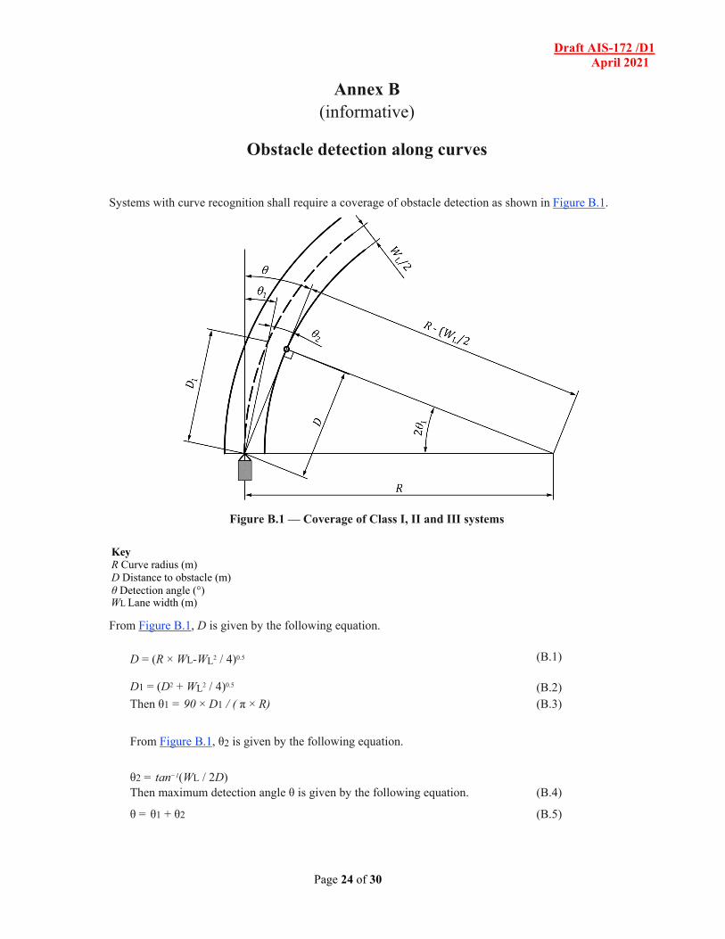
Systems with curve recognition shall require a coverage of obstacle detection as shown in Figure B.1.
Figure B.1 — Coverage of Class I, II and III systems
Key R Curve radius (m) D Distance to obstacle (m) θ Detection angle (°) WL Lane width (m)
From Figure B.1, D is given by the following equation.
From Figure B.1, θ2 is given by the following equation.
θ2 = tan−1(WL / 2D)
(B.3)
Then maximum detection angle θ is given by the following equation. (B.4)
θ = θ1 + θ2 (B.5)
Draft AIS-172 /D1 April 2021
Page 25 of 30
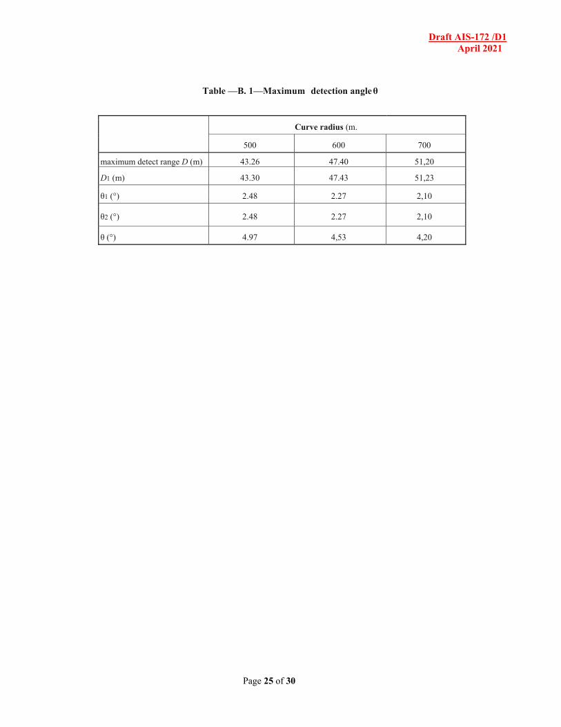
Table —B. 1—Maximum detection angle θ
Curve radius (m.
500 600 700
maximum detect range D (m) 43.26 47.40 51,20
D1 (m) 43.30 47.43 51,23
θ1 (°) 2.48 2.27 2,10
θ2 (°) 2.48 2.27 2,10
θ (°) 4.97 4,53 4,20
Draft AIS-172 /D1 April 2021
Page 26 of 30
Annex C (informative)
Laser radar – Coefficient of test target
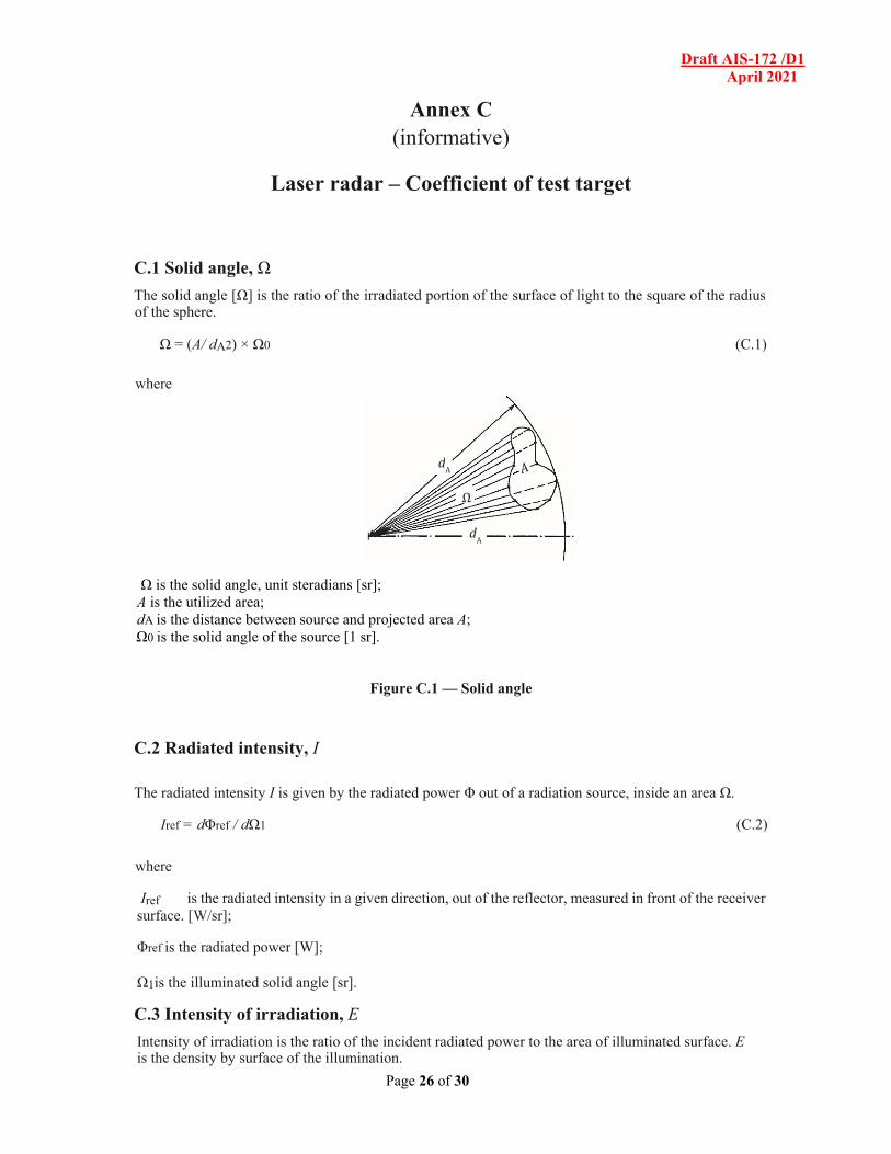
C.1 Solid angle, Ω
The solid angle [Ω] is the ratio of the irradiated portion of the surface of light to the square of the radius of the sphere.
Ω = (A/ dA2) × Ω0 (C.1)
where
Ω is the solid angle, unit steradians [sr]; A is the utilized area; dA is the distance between source and projected area A; Ω0 is the solid angle of the source [1 sr].
Figure C.1 — Solid angle
C.2 Radiated intensity, I
The radiated intensity I is given by the radiated power Φ out of a radiation source, inside an area Ω.
Iref = dΦref / dΩ1 (C.2)
where
Iref is the radiated intensity in a given direction, out of the reflector, measured in front of the receiver surface. [W/sr];
Φref is the radiated power [W];
Ω1is the illuminated solid angle [sr].
C.3 Intensity of irradiation, E
Intensity of irradiation is the ratio of the incident radiated power to the area of illuminated surface. E is the density by surface of the illumination.
d A
d A
Ω
Draft AIS-172 /D1 April 2021
Page 27 of 30
Et = dΦt / dAt (C.3)
where
Et is the intensity of irradiation, received from the transmitter at target level [W/m2];
Φt is the radiated power [W]
At is the illuminated surface [m2].
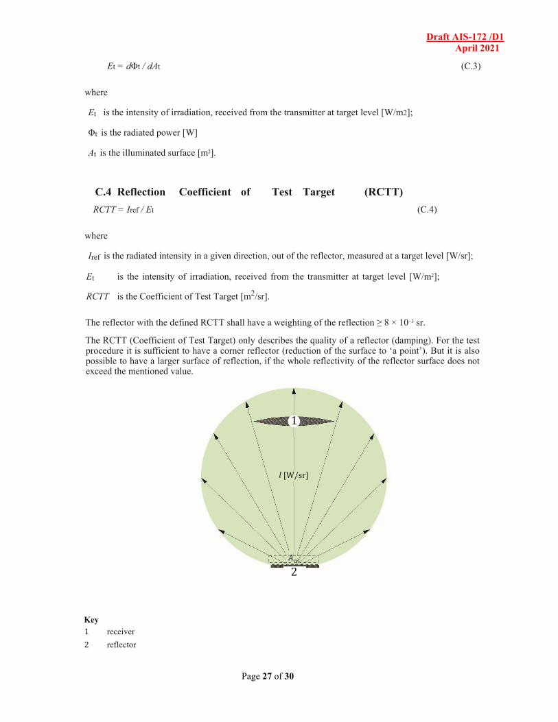
C.4 Reflection Coefficient of Test Target (RCTT)
RCTT = Iref / Et (C.4)
where
Iref is the radiated intensity in a given direction, out of the reflector, measured at a target level [W/sr];
Et is the intensity of irradiation, received from the transmitter at target level [W/m2];
RCTT is the Coefficient of Test Target [m2/sr].
The reflector with the defined RCTT shall have a weighting of the reflection ≥ 8 × 10⁻³ sr.
The RCTT (Coefficient of Test Target) only describes the quality of a reflector (damping). For the test procedure it is sufficient to have a corner reflector (reduction of the surface to ‘a point’). But it is also possible to have a larger surface of reflection, if the whole reflectivity of the reflector surface does not exceed the mentioned value.
Key 1 receiver
2 reflector
1
2
I [W/sr]
A ref
Draft AIS-172 /D1 April 2021
Page 28 of 30
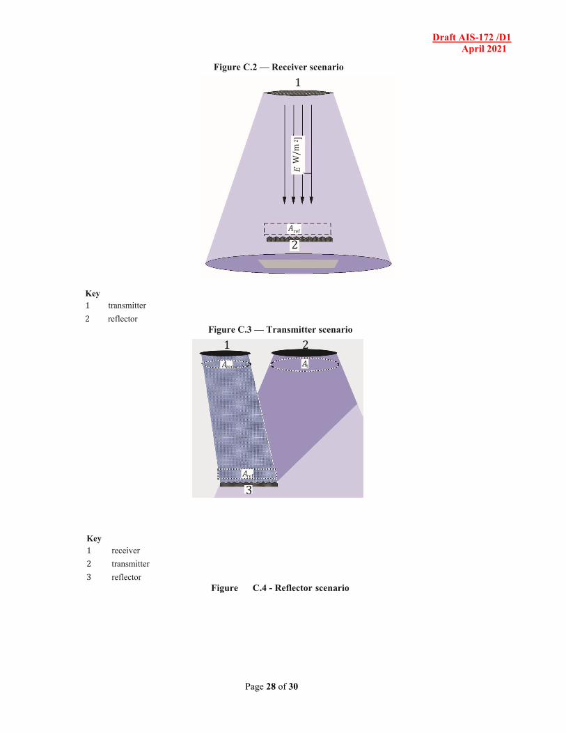
Figure C.2 — Receiver scenario
Key 1 transmitter
2 reflector Figure C.3 — Transmitter scenario
Key 1 receiver
2 transmitter
3 reflector Figure C.4 - Reflector scenario
A ref
1
2
1 2
3
A ref
A rec A t
Draft AIS-172 /D1 April 2021
Page 29 of 30
Annex D (informative)
Radio wave radar test target geometry
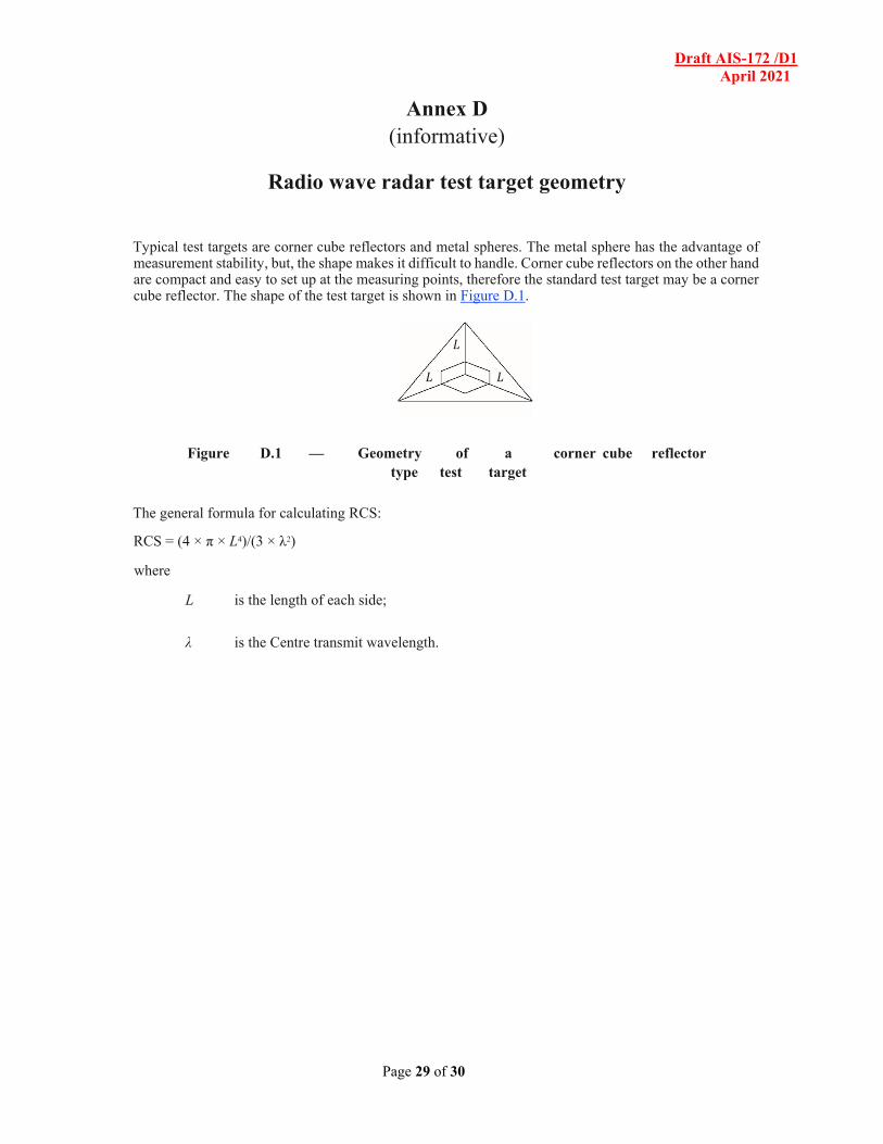
Typical test targets are corner cube reflectors and metal spheres. The metal sphere has the advantage of measurement stability, but, the shape makes it difficult to handle. Corner cube reflectors on the other hand are compact and easy to set up at the measuring points, therefore the standard test target may be a corner cube reflector. The shape of the test target is shown in Figure D.1.
Figure D.1 — Geometry of a corner cube reflector type test target
The general formula for calculating RCS:
RCS = (4 × π × L4)/(3 × λ2)
where
L is the length of each side;
λ is the Centre transmit wavelength.
L
L L
Draft AIS-172 /D1 April 2021
Page 30 of 30
Annexure 1
(To be elaborated further)
Technical Information to be submitted by the Vehicle Manufacturer
1. Trademark: ........................................................................................ 2. Type and trade name(s):........................................................................ 3. Name and address of manufacturer:........................................................ 4. If applicable, name and address of manufacturer’s representative:...... 5. Brief description of vehicle:................................................................ 6. Data to enable the identification of the type of FVCWS 7. Brief description of FVCWS system:........................... 8. Whether the system comply with AIS-004(Part 3) :........................... 9. Whether optional Haptic warning used