Draft ETSI EN 301 459 V1.2.6 (2004-12) Candidate Harmonized European Standard (Telecommunications series) Satellite Earth Stations and Systems (SES); Harmonized EN for Satellite Interactive Terminals (SIT) and Satellite User Terminals (SUT) transmitting towards satellites in geostationary orbit in the 29,5 GHz to 30,0 GHz frequency bands covering essential requirements under article 3.2 of the R&TTE Directive
Transcript
Draft ETSI EN 301 459 V1.2.6 (2004-12)
Candidate Harmonized European Standard (Telecommunications series)
Satellite Earth Stations and Systems (SES);Harmonized EN for Satellite Interactive Terminals (SIT)
and Satellite User Terminals (SUT)transmitting towards satellites in geostationary orbit
in the 29,5 GHz to 30,0 GHz frequency bandscovering essential requirements
under article 3.2 of the R&TTE Directive
ETSI
Draft ETSI EN 301 459 V1.2.6 (2004-12) 2
Reference REN/SES-00108
Keywords FSS, earth station, satellite, terminal
ETSI
650 Route des Lucioles F-06921 Sophia Antipolis Cedex - FRANCE
Tel.: +33 4 92 94 42 00 Fax: +33 4 93 65 47 16
Siret N° 348 623 562 00017 - NAF 742 C
Association à but non lucratif enregistrée à la Sous-Préfecture de Grasse (06) N° 7803/88
Important notice
Individual copies of the present document can be downloaded from: http://www.etsi.org
The present document may be made available in more than one electronic version or in print. In any case of existing or perceived difference in contents between such versions, the reference version is the Portable Document Format (PDF).
In case of dispute, the reference shall be the printing on ETSI printers of the PDF version kept on a specific network drive within ETSI Secretariat.
Users of the present document should be aware that the document may be subject to revision or change of status. Information on the current status of this and other ETSI documents is available at
http://portal.etsi.org/tb/status/status.asp
If you find errors in the present document, please send your comment to one of the following services: http://portal.etsi.org/chaircor/ETSI_support.asp
Copyright Notification
No part may be reproduced except as authorized by written permission. The copyright and the foregoing restriction extend to reproduction in all media.
DECTTM, PLUGTESTSTM and UMTSTM are Trade Marks of ETSI registered for the benefit of its Members. TIPHONTM and the TIPHON logo are Trade Marks currently being registered by ETSI for the benefit of its Members. 3GPPTM is a Trade Mark of ETSI registered for the benefit of its Members and of the 3GPP Organizational Partners.
Intellectual Property Rights ................................................................................................................................6
5 Testing for compliance with technical requirements..............................................................................22 5.1 Environmental conditions for testing ...............................................................................................................22 5.2 Essential radio test suites..................................................................................................................................22
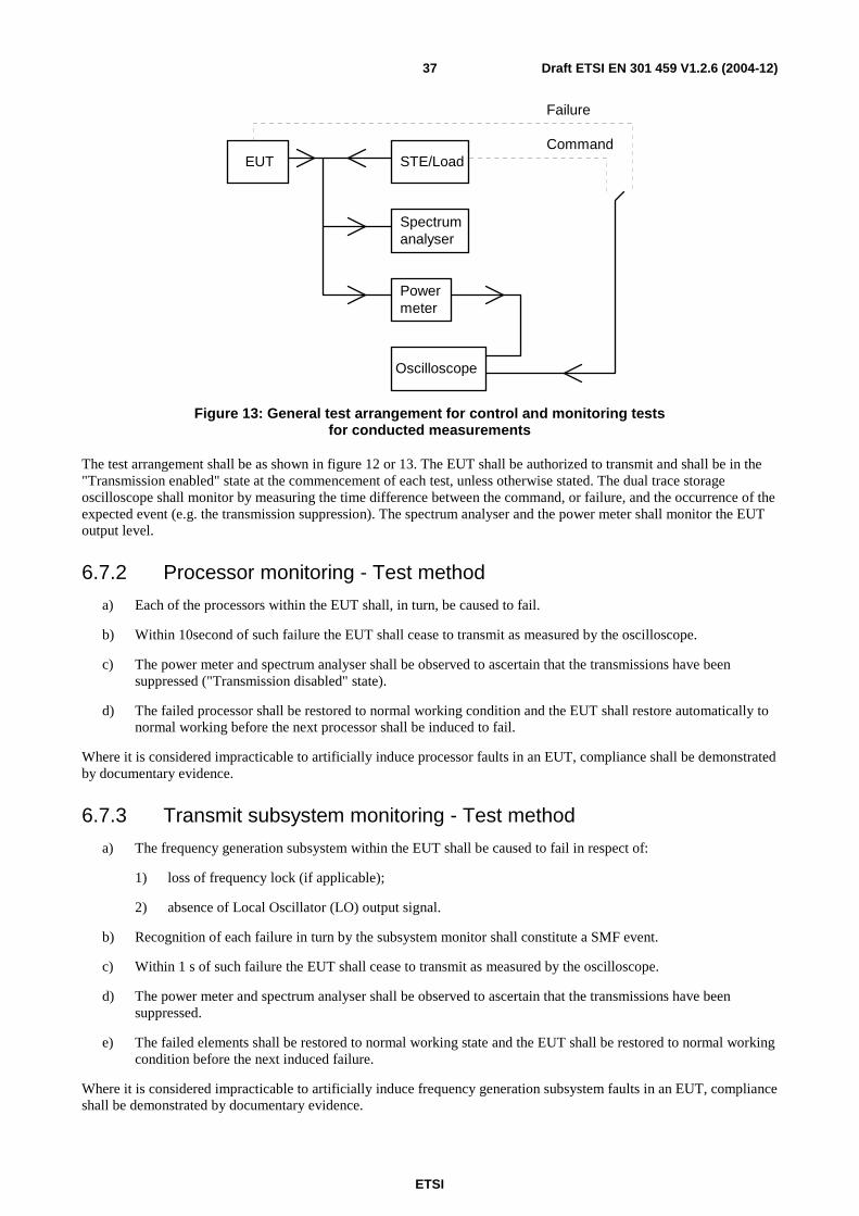
6 Test method............................................................................................................................................22 6.1 General .............................................................................................................................................................22 6.2 Off-axis spurious radiation ...............................................................................................................................23 6.2.1 Test method ................................................................................................................................................23 6.2.1.1 Up to 1 000 MHz ..................................................................................................................................23 6.2.1.1.1 Test site............................................................................................................................................23 6.2.1.1.2 Measuring receivers.........................................................................................................................24 6.2.1.1.3 Procedure.........................................................................................................................................24 6.2.1.2 Above 1 000 MHz.................................................................................................................................24 6.2.1.2.1 Identification of the significant frequencies of spurious radiation ..................................................24 6.2.1.2.2 Measurement of radiated power levels of identified spurious radiation ..........................................25 6.2.1.2.3 Measurement of conducted spurious radiation at the antenna flange ..............................................26 6.3 On-axis spurious radiation................................................................................................................................27 6.3.1 Test method ................................................................................................................................................27 6.3.1.1 Test site .................................................................................................................................................27 6.3.1.2 Method of measurement........................................................................................................................27 6.3.1.2.1 General ............................................................................................................................................27 6.3.1.2.2 Method of measurement at the antenna flange ................................................................................27 6.3.1.2.3 Method of measurement for an EUT with antenna..........................................................................28 6.4 Off-axis EIRP emission density within the band..............................................................................................29 6.4.1 Test method ................................................................................................................................................29 6.4.1.1 Transmit output power density..............................................................................................................29 6.4.1.1.1 General ............................................................................................................................................29 6.4.1.1.2 Test site............................................................................................................................................29 6.4.1.1.3 Method of measurement ..................................................................................................................30 6.4.1.2 Antenna transmit gain ...........................................................................................................................31 6.4.1.2.1 General ............................................................................................................................................31 6.4.1.2.2 Test site............................................................................................................................................31 6.4.1.2.3 Method of measurement ..................................................................................................................31 6.4.1.3 Antenna transmit radiation patterns ......................................................................................................32 6.4.1.3.1 General ............................................................................................................................................32 6.4.1.3.2 Test site............................................................................................................................................32 6.4.1.3.3 Test arrangement .............................................................................................................................32 6.4.1.3.4 Co-polar radiation pattern - azimuth................................................................................................32 6.4.1.3.5 Co-polar radiation pattern - elevation..............................................................................................33 6.4.1.3.6 Cross-polar radiation pattern - azimuth ...........................................................................................34 6.4.1.3.7 Cross-polar radiation pattern - elevation .........................................................................................34 6.4.2 Computation of results................................................................................................................................35 6.5 Carrier suppression...........................................................................................................................................35 6.6 Antenna pointing for STs .................................................................................................................................35 6.7 ST Control and Monitoring Functions (CMF)..................................................................................................36 6.7.1 Test arrangement ........................................................................................................................................36 6.7.2 Processor monitoring - Test method ...........................................................................................................37 6.7.3 Transmit subsystem monitoring - Test method...........................................................................................37 6.7.4 Power-on/Reset - Test method....................................................................................................................38 6.7.5 Control Channel (CC) reception - Test method ..........................................................................................38 6.7.6 Network Control commands - Test method ................................................................................................39 6.7.7 Initial burst transmission - Test method......................................................................................................40
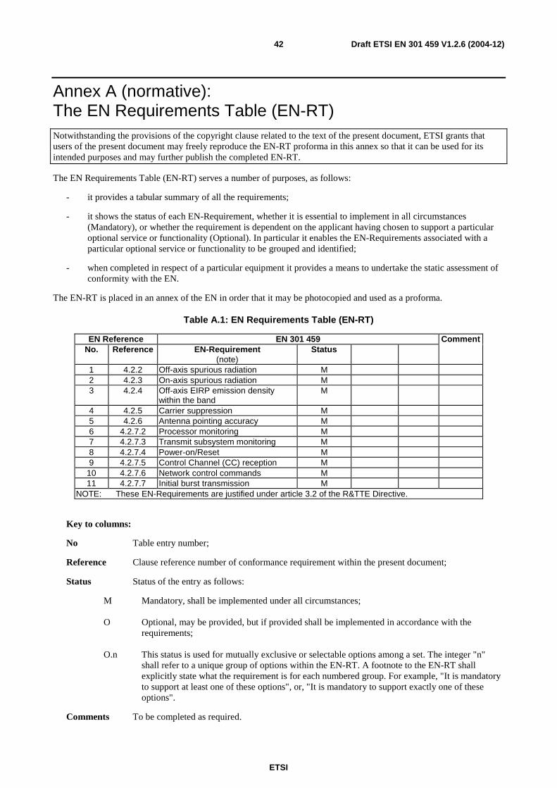
Annex A (normative): The EN Requirements Table (EN-RT) ........................................................42
ETSI
Draft ETSI EN 301 459 V1.2.6 (2004-12) 5
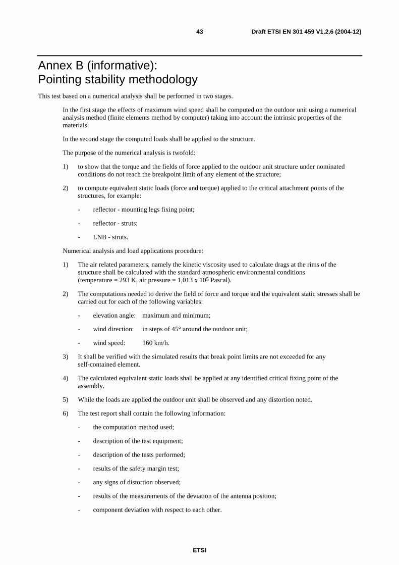
Annex B (informative): Pointing stability methodology .....................................................................43
Annex C (informative): The EN title in the official languages ...........................................................44
Annex D (informative): Bibliography...................................................................................................45
History ..............................................................................................................................................................46
ETSI
Draft ETSI EN 301 459 V1.2.6 (2004-12) 6
Intellectual Property Rights IPRs essential or potentially essential to the present document may have been declared to ETSI. The information pertaining to these essential IPRs, if any, is publicly available for ETSI members and non-members, and can be found in ETSI SR 000 314: "Intellectual Property Rights (IPRs); Essential, or potentially Essential, IPRs notified to ETSI in respect of ETSI standards", which is available from the ETSI Secretariat. Latest updates are available on the ETSI Web server (http://webapp.etsi.org/IPR/home.asp).
Pursuant to the ETSI IPR Policy, no investigation, including IPR searches, has been carried out by ETSI. No guarantee can be given as to the existence of other IPRs not referenced in ETSI SR 000 314 (or the updates on the ETSI Web server) which are, or may be, or may become, essential to the present document.
Foreword This Candidate Harmonized European Standard (Telecommunications series) has been produced by ETSI Technical Committee Satellite Earth Stations and Systems (SES), and is now submitted for the Public Enquiry phase of the ETSI standards Two-step Approval Procedure.
The present document has been produced by ETSI in response to a mandate from the European Commission issued under Council Directive 98/34/EC [1] (as amended) laying down a procedure for the provision of information in the field of technical standards and regulations.
The present document is intended to become a Harmonized Standard, the reference of which will be published in the Official Journal of the European Communities referencing the Directive 1999/5/EC [2] of the European Parliament and of the Council of 9 March 1999 on radio equipment and telecommunications terminal equipment and the mutual recognition of their conformity ("the R&TTE Directive").
Technical specifications relevant to Directive 1999/5/EC [2] are given in annex A.
Proposed national transposition dates
Date of latest announcement of this EN (doa): 3 months after ETSI publication
Date of latest publication of new National Standard or endorsement of this EN (dop/e):
6 months after doa
Date of withdrawal of any conflicting National Standard (dow): 6 months after doa
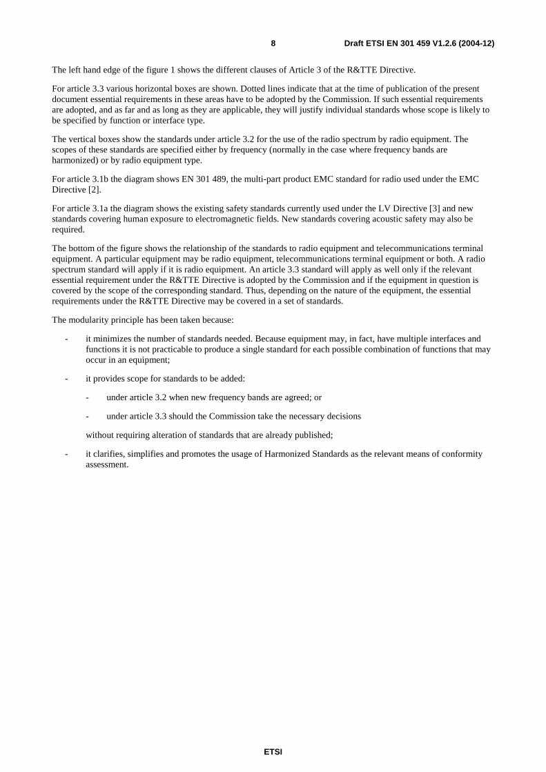
Introduction ETSI has designed a modular structure for the standards. Each standard is a module in the structure. The modular structure is shown in figure 1.
- If needed, new standards for human exposure to Electromagnetic Fields,
- if needed, new standards for acoustic safety
Use of spectrum
* If needed Scoped by equipment class or type
Scoped by frequency and/or equipment type
Disability*
Privacy*
Fraud*
No harm to the network*
Emergency*
Inter-working via the network*
Inter-working with the network
Non-radio Radio (RE)
Non-TTE TTE
3.1b
3.2
3.3c
3.3b
3.3a
3.3d
3.3e
3.3f
Radio Product EMC
EN 301 489 multi-part EMC standard
Generic and product standards also notified under EMC Directive
Standards also notified under LV Directive
3.1a
New radio harmonized standards Spectrum
EMC
Safety
Figure 1: Modular structure for the various standards used under the R&TTE Directive
The left hand edge of the figure shows the different clauses of article 3 of the Directive.
ETSI
Draft ETSI EN 301 459 V1.2.6 (2004-12) 8
The left hand edge of the figure 1 shows the different clauses of Article 3 of the R&TTE Directive.
For article 3.3 various horizontal boxes are shown. Dotted lines indicate that at the time of publication of the present document essential requirements in these areas have to be adopted by the Commission. If such essential requirements are adopted, and as far and as long as they are applicable, they will justify individual standards whose scope is likely to be specified by function or interface type.
The vertical boxes show the standards under article 3.2 for the use of the radio spectrum by radio equipment. The scopes of these standards are specified either by frequency (normally in the case where frequency bands are harmonized) or by radio equipment type.
For article 3.1b the diagram shows EN 301 489, the multi-part product EMC standard for radio used under the EMC Directive [2].
For article 3.1a the diagram shows the existing safety standards currently used under the LV Directive [3] and new standards covering human exposure to electromagnetic fields. New standards covering acoustic safety may also be required.
The bottom of the figure shows the relationship of the standards to radio equipment and telecommunications terminal equipment. A particular equipment may be radio equipment, telecommunications terminal equipment or both. A radio spectrum standard will apply if it is radio equipment. An article 3.3 standard will apply as well only if the relevant essential requirement under the R&TTE Directive is adopted by the Commission and if the equipment in question is covered by the scope of the corresponding standard. Thus, depending on the nature of the equipment, the essential requirements under the R&TTE Directive may be covered in a set of standards.
The modularity principle has been taken because:
- it minimizes the number of standards needed. Because equipment may, in fact, have multiple interfaces and functions it is not practicable to produce a single standard for each possible combination of functions that may occur in an equipment;
- it provides scope for standards to be added:
- under article 3.2 when new frequency bands are agreed; or
- under article 3.3 should the Commission take the necessary decisions
without requiring alteration of standards that are already published;
- it clarifies, simplifies and promotes the usage of Harmonized Standards as the relevant means of conformity assessment.
ETSI
Draft ETSI EN 301 459 V1.2.6 (2004-12) 9
1 Scope The present document applies to Satellite Interactive Terminals (SIT) and Satellite User Terminals (SUT) operating as part of a bi-directional satellite network. Satellite Terminal (ST) is used in the present document as a generic name that refers equally to a SIT and/or a SUT.
In such a network a Network Control Facility (NCF) is responsible for the monitoring and control of the transmit functions of the STs. These STs have the following characteristics:
- in the case of SITs reception is in the Fixed Satellite Service (FSS) frequency ranges from 10,70 GHz to 11,70 GHz and from 12,50 GHz to 12,75 GHz as well as the Broadcast Satellite Service (BSS) frequency range from 11,70 GHz to 12,50 GHz;
- in the case of SUTs reception is in the Fixed Satellite Service (FSS) frequency ranges from 19,70 GHz to 20,20 GHz and from 17,70 GHz to 19,70 GHz as well as the Broadcast Satellite Service (BSS) frequency range from 21,40 GHz to 22,00 GHz;
- in all cases ST transmission is in the frequency band allocated to FSS on a primary basis from 29,5 GHz to 30,0 GHz;
- STs transmit through geostationary satellites with spacing down to 2° away from any other geostationary satellite operating in the same frequency band and covering the same area;
- linear or circular polarization is used for transmission or reception;
- the received signals may be analogue and/or digital;
- the transmitted signals are always of digital nature;
- the ST antenna diameter does not exceed 1,8 m, or equivalent corresponding aperture;
- the ST is designed for unattended operations.
The equipment considered in the present document comprises both the outdoor unit, usually composed of the antenna subsystem and associated upconverter, power amplifier and Low Noise Block (LNB) downconverter, and the indoor unit, usually composed of receive and transmit logic as well as the modulator, including cables between these two units.
The present document applies to the ST with its ancillary equipment and its various ports and when operated within the boundary limits of all the operational environmental profile declared by the applicant and when installed as required by the applicant by declaration or in the user documentation.
All parts of the indoor unit related to reception, processing and presentation of the received information except the control channel are not within the scope of the present document. The syntax of the control channel messages is outside the scope of the present document.
The present document is intended to cover the provisions of Directive 1999/5/EC [2] (R&TTE Directive) article 3.2, which states that "….. radio equipment shall be so constructed that it effectively uses the spectrum allocated to terrestrial/space radio communications and orbital resources so as to avoid harmful interference".
In addition to the present document, other ENs that specify technical requirements in respect of essential requirements under other parts of article 3 of the R&TTE Directive [1] may apply to equipment within the scope of the present document.
NOTE: A list of such ENs is included on the web site http://www.newapproach.org/.
2 References The following documents contain provisions which, through reference in this text, constitute provisions of the present document.
• References are either specific (identified by date of publication and/or edition number or version number) or non-specific.
• For a specific reference, subsequent revisions do not apply.
• For a non-specific reference, the latest version applies.
Referenced documents which are not found to be publicly available in the expected location might be found at http://docbox.etsi.org/Reference.
[1] Directive 98/34/EC of the European Parliament and of the Council of 22 June 1998 laying down a procedure for the provision of information in the field of technical standards and regulations.
[2] Directive 1999/5/EC of the European Parliament and of the Council of 9 March 1999 on radio equipment and telecommunications terminal equipment and the mutual recognition of their conformity (R&TTE Directive).
[3] CISPR No 16-1-4 (Edition 1.1): "Specification for radio disturbance and immunity measuring apparatus and methods - Part 1-4: Radio disturbance and immunity measuring apparatus - Ancillary equipment - Radiated disturbances".
[4] ETSI EN 301 358 (V1.1.1): "Satellite Earth Stations and Systems (SES); Satellite User Terminals (SUT) using satellites in geostationary orbit operating in the 19,7 GHz to 20,2 GHz (space-to-earth) and 29,5 GHz to 30 GHz (earth-to-space) frequency bands".
[5] ETSI EN 301 359 (V1.1.1): "Satellite Earth Stations and Systems (SES); Satellite Interactive Terminals (SIT) using satellites in geostationary orbit operating in the 11 GHz to 12 GHz (space-to-earth) and 29,5 GHz to 30,0 GHz (earth-to-space) frequency bands".
[6] ETSI EN 300 421 (V1.1.2): "Digital Video Broadcasting (DVB); Framing structure, channel coding and modulation for 11/12 GHz satellite services".
3 Definitions and abbreviations
3.1 Definitions For the purpose of the present document, the terms and definitions given in the R&TTE Directive [1] and the following apply:
ancillary equipment: equipment used in connection with a ST is considered as ancillary if the three following conditions are meet:
a) the equipment is intended for use in conjunction with the ST to provide additional operational and/or control features; and
b) the equipment can not be used on a stand alone basis, to provide user functions independently of the ST; and
c) the absence of the equipment does not inhibit the operation of the ST
applicant: manufacturer or his authorized representative within the European Community or the person responsible for placing the apparatus on the market
carrier-off state: ST is in this state when it is authorized by the Network Control Facility (NCF) to transmit, but when it does not transmit any signal
NOTE: The existence of a carrier-off state depends on the system of transmission used. For STs designed for continuous transmission mode there may be no carrier-off state.
carrier-on state: ST is in this state when it is authorized by the NCF to transmit and when it transmits a signal in a continuous or non-continuous mode
Control Channel (CC): channel or channels by which STs receive control information from the NCF for their network
NOTE: Typically the CC(s) is/are carried via the same or collocated satellite as used for transmission of user data and within the internal protocol structure of the broadcast system.
EIRPmax: maximum EIRP capability of the ST as declared by the applicant
EIRPnom: either
i. when uplink power control is not implemented EIRPmax, or
ii. when uplink power control is implemented, the maximum required EIRP of the ST under clear sky condition as declared by the applicant
NOTE: The applicant may declare different values of EIRPmax and EIRPnom for each combination of occupied
bandwidth and transmission parameters (see clause 4.2.1).
Environmental profile: range of environmental conditions
indoor unit: it is composed of that part of the ST which is not part of the outdoor unit
NOTE: It is generally installed inside a building and is connected to the outdoor unit.
integral antenna: antenna which may not be removed during the tests according to the applicant's statement
nominated bandwidth: bandwidth of the ST radio frequency transmission nominated by the applicant
NOTE 1: The nominated bandwidth does not exceed 5 times the occupied bandwidth.
NOTE 2: The nominated bandwidth is wide enough to encompass all spectral elements of the transmission which have a level greater than the specified spurious radiation limits. The nominated bandwidth is wide enough to take account of the transmit carrier frequency stability. This definition is chosen to allow flexibility regarding adjacent channel interference levels which will be taken into account by operational procedures depending on the exact transponder carrier assignment situation.
occupied bandwidth: width of the signal spectrum 10 dB below the maximum inband density
outdoor unit: those parts of the ST intended to be installed outdoor, as declared by the applicant, or as indicated in the user documentation
The outdoor unit usually comprises of three main parts:
a) the antenna sub-system which converts the incident radiation field into a guided wave and vice versa;
b) the Low Noise Block (LNB) downconverter, which is a device that amplifies, with very low internal noise, the received signals in the Radio Frequency (RF) band and converts them to Intermediate Frequencies (IF);
c) the upconverter and the power amplifier which convert from the IF to RF and amplify the low level RF signals for transmission through the antenna subsystem.
NOTE: The installation equipment is outside the scope of the present document. However, the antenna structures and other components directly mounted on the antenna and forming an integral part of it, are subject to the specifications of the present document.
port: particular interface of the specified apparatus with the external electromagnetic environment (figure 2 of EN 301 459)
ETSI
Draft ETSI EN 301 459 V1.2.6 (2004-12) 12
APPARATUS
Signal/control port
Earth port
Mains power port
DC power port
Enclosure port
Antenna Port
Earth portTelecom Port
Figure 2: Examples of ports
Figure 3: Void
removable antenna: antenna which may be removed during the tests according to the applicant's statement
Satellite Terminal (ST): throughout the present document either a SIT or a SUT
spurious radiation: any radiation outside the nominated bandwidth
transmission disabled state: ST is in this state when it is not authorized by the NCF to transmit
3.2 Abbreviations For the purpose of the present document, the following abbreviations apply:
BSS Broadcast Satellite Service CC Control Channel CCF Control Channel reception Failure CCR Control Channel correctly Received CISPR Comité International Spécial des Perturbations Radioélectriques (International Special Committee
on Radio Interference) CMF Control and Monitoring Functions CDMA Code Division Multiple Access EIRP Equivalent Isotropically Radiated Power EUT Equipment Under Test FDMA Frequency Division Multiple Access FEC Forward Error Correction FSS Fixed Satellite Service IF Intermediate Frequencies LNB Low Noise Block downconverter LO Local Oscillator NCF Network Control Facility RF Radio Frequency R&TTE Radio and Telecommunications Terminal Equipment SIT Satellite Interactive Terminal SMF System Monitoring Fail SMP System Monitoring Pass ST Satellite Terminal STE Special Test Equipment SUT Satellite User Terminal TDMA Time Division Multiple Access TxD Transmission Disable command TxE Transmission Enable command
ETSI
Draft ETSI EN 301 459 V1.2.6 (2004-12) 13
4 Technical requirements specifications
4.1 Environmental profile The technical requirements of the present document apply under the environmental profile for operation of the equipment, which shall be declared by the applicant. The equipment shall comply with all the technical requirements of the present document at all times when operating within the boundary limits of the declared operational environmental profile.
The environmental profile for operation of the equipment shall include the ranges of humidity, temperature and supply voltage.
4.2 Conformance requirements
4.2.1 General
Under operational conditions a ST may dynamically change the occupied bandwidth and/or other transmission parameters (e.g. FEC, modulation, symbol rate) of the transmitted signal. For each combination of occupied bandwidth and other transmission parameters, an EIRPmax, an EIRPnom and a nominated bandwidth shall be declared by the
applicant. The following specifications apply to the ST for each combination of occupied bandwidth and other transmission parameters.
4.2.2 Off-axis spurious radiation
4.2.2.1 Purpose
To limit the level of interference to terrestrial and satellite radio services.
4.2.2.2 Specification
The following specifications apply to the ST transmitting at EIRP values up to and including EIRPmax.
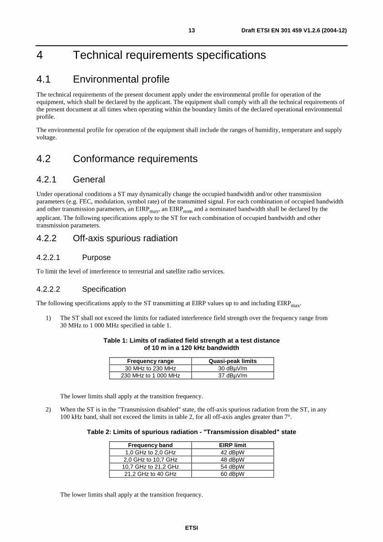
1) The ST shall not exceed the limits for radiated interference field strength over the frequency range from 30 MHz to 1 000 MHz specified in table 1.
Table 1: Limits of radiated field strength at a test distance of 10 m in a 120 kHz bandwidth
Frequency range Quasi-peak limits 30 MHz to 230 MHz 30 dBµV/m
230 MHz to 1 000 MHz 37 dBµV/m
The lower limits shall apply at the transition frequency.
2) When the ST is in the "Transmission disabled" state, the off-axis spurious radiation from the ST, in any 100 kHz band, shall not exceed the limits in table 2, for all off-axis angles greater than 7°.
Table 2: Limits of spurious radiation - "Transmission disabled" state
Frequency band EIRP limit 1,0 GHz to 2,0 GHz 42 dBpW
2,0 GHz to 10,7 GHz 48 dBpW 10,7 GHz to 21,2 GHz 54 dBpW 21,2 GHz to 40 GHz 60 dBpW
The lower limits shall apply at the transition frequency.
ETSI
Draft ETSI EN 301 459 V1.2.6 (2004-12) 14
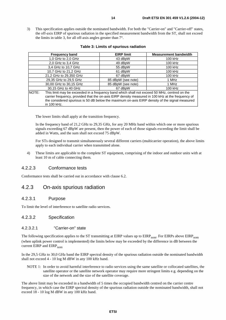
3) This specification applies outside the nominated bandwidth. For both the "Carrier-on" and "Carrier-off" states, the off-axis EIRP of spurious radiation in the specified measurement bandwidth from the ST, shall not exceed the limits in table 3, for all off-axis angles greater than 7°.
Table 3: Limits of spurious radiation
Frequency band EIRP limit Measurement bandwidth 1,0 GHz to 2,0 GHz 43 dBpW 100 kHz 2,0 GHz to 3,4 GHz 49 dBpW 100 kHz
3,4 GHz to 10,7 GHz 55 dBpW 100 kHz 10,7 GHz to 21,2 GHz 61 dBpW 100 kHz
21,2 GHz to 29,350 GHz 67 dBpW 100 kHz 29,35 GHz to 29,5 GHz 85 dBpW (see note) 1 MHz 30,00 GHz to 30,15 GHz 85 dBpW (see note) 1 MHz
30,15 GHz to 40 GHz 67 dBpW 100 kHz NOTE: This limit may be exceeded in a frequency band which shall not exceed 50 MHz, centred on the
carrier frequency, provided that the on-axis EIRP density measured in 100 kHz at the frequency of the considered spurious is 50 dB below the maximum on-axis EIRP density of the signal measured in 100 kHz.
The lower limits shall apply at the transition frequency.
In the frequency band of 21,2 GHz to 29,35 GHz, for any 20 MHz band within which one or more spurious signals exceeding 67 dBpW are present, then the power of each of those signals exceeding the limit shall be added in Watts, and the sum shall not exceed 75 dBpW.
For STs designed to transmit simultaneously several different carriers (multicarrier operation), the above limits apply to each individual carrier when transmitted alone.
4) These limits are applicable to the complete ST equipment, comprising of the indoor and outdoor units with at least 10 m of cable connecting them.
4.2.2.3 Conformance tests
Conformance tests shall be carried out in accordance with clause 6.2.
4.2.3 On-axis spurious radiation
4.2.3.1 Purpose
To limit the level of interference to satellite radio services.
4.2.3.2 Specification
4.2.3.2.1 "Carrier-on" state
The following specification applies to the ST transmitting at EIRP values up to EIRPnom. For EIRPs above EIRPnom
(when uplink power control is implemented) the limits below may be exceeded by the difference in dB between the current EIRP and EIRPnom
In the 29,5 GHz to 30,0 GHz band the EIRP spectral density of the spurious radiation outside the nominated bandwidth shall not exceed 4 - 10 log M dBW in any 100 kHz band.
NOTE 1: In order to avoid harmful interference to radio services using the same satellite or collocated satellites, the satellite operator or the satellite network operator may require more stringent limits e.g. depending on the size of the network and the size of the satellite coverage.
The above limit may be exceeded in a bandwidth of 5 times the occupied bandwidth centred on the carrier centre frequency, in which case the EIRP spectral density of the spurious radiation outside the nominated bandwidth, shall not exceed 18 - 10 log M dBW in any 100 kHz band.
ETSI
Draft ETSI EN 301 459 V1.2.6 (2004-12) 15
M is the maximum number of STs which are expected to transmit simultaneously in the same carrier frequency band. This number shall not be exceeded for more than 0,01 % of the time. The value of M and the operational conditions of the system shall be declared by the applicant.
NOTE 2: The on-axis spurious radiation, outside the 29,5 GHz to 30,0 GHz band, are indirectly limited by clause 4.2.2.2. Consequently no specification is needed.
NOTE 3: Intermodulation limits inside the band 29,5 GHz to 30,0 GHz are to be determined by system design and are subject to satellite operator specifications.
For ST designed to transmit simultaneously several different carriers (multicarrier operation), the above limits only apply to each individual carrier when transmitted alone.
4.2.3.2.2 "Carrier-off" and "Transmission disabled" state
In the 29,5 GHz to 30,0 GHz band the EIRP spectral density of the spurious radiation outside the nominated bandwidth shall not exceed -21 dBW in any 100 kHz band.
NOTE: In order to avoid harmful interference to radio services using the same satellite or collocated satellites, the satellite operator or the satellite network operator may require more stringent limits e.g. depending on the size of the network and the size of the satellite coverage.
4.2.3.3 Conformance tests
Conformance tests shall be carried out in accordance with clause 6.3.
4.2.4 Off-axis EIRP emission density within the band
4.2.4.1 Purpose
Protection of other satellite (uplink) systems.
4.2.4.2 Specification
The following specifications apply to the ST transmitting at EIRP values up to EIRPmax.
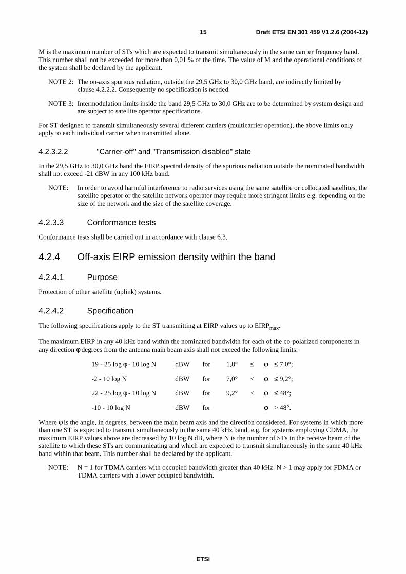
The maximum EIRP in any 40 kHz band within the nominated bandwidth for each of the co-polarized components in any direction φ degrees from the antenna main beam axis shall not exceed the following limits:
19 - 25 log φ - 10 log N dBW for 1,8° ≤ φ ≤ 7,0°;
-2 - 10 log N dBW for 7,0° < φ ≤ 9,2°;
22 - 25 log φ - 10 log N dBW for 9,2° < φ ≤ 48°;
-10 - 10 log N dBW for φ > 48°.
Where φ is the angle, in degrees, between the main beam axis and the direction considered. For systems in which more than one ST is expected to transmit simultaneously in the same 40 kHz band, e.g. for systems employing CDMA, the maximum EIRP values above are decreased by 10 log N dB, where N is the number of STs in the receive beam of the satellite to which these STs are communicating and which are expected to transmit simultaneously in the same 40 kHz band within that beam. This number shall be declared by the applicant.
NOTE: N = 1 for TDMA carriers with occupied bandwidth greater than 40 kHz. N > 1 may apply for FDMA or TDMA carriers with a lower occupied bandwidth.
ETSI
Draft ETSI EN 301 459 V1.2.6 (2004-12) 16
In addition the maximum EIRP in any 40 kHz band within the nominated bandwidth of each of the cross-polarized components in any direction φ degrees from the antenna main beam axis shall not exceed the following limits:
9 - 25 log φ - 10 log N dBW for 1,8° ≤ φ ≤ 7,0°;
-12 - 10 log N dBW for 7,0° < φ ≤ 9,2°,
where φ and N are as defined above.
For non-continuous transmission, the above limits may not apply for a specific portion of each burst as declared by the applicant. This excluded portion shall not exceed 50 µsec or 10 % of the burst, whichever is the smaller.
The excluded portion shall have characteristics similar to the remaining part of the burst:
- same symbol rate and modulation; and
- same or lower maximum amplitude.
In the case of STs employing uplink power density control, the above limits, for co-polar and cross-polar components, shall apply under clear-sky conditions and these limits include all additional margins above the minimum clear-sky level necessary for the implementations of uplink power density control. For STs implementing uplink power density control, the above limits may be exceeded by up to A dB during fade conditions, where A is the attenuation of the transmit signal relative to clear sky conditions, but no more than 20 dB.
In the case of STs employing transmission parameter modification (e.g. FEC, modulation, symbol rate) of the transmitted signal as part of uplink power density control, the above limits shall apply to all combinations of occupied bandwidth and transmission parameters as declared by the applicant.
Any antenna off-axis direction may be defined by a pair of values (α, φ) where φ is the off-axis angle of that direction with the antenna main beam axis and α is the angle of the plane defined by that direction and the antenna main beam axis with an arbitrary reference plane containing the antenna main beam axis. The range of values of φ and α is from φmin - δφ to 180° for φ, and from -180° to +180° for α.
The above limits apply to any off-axis direction (α, φ) within ±3° of the visible part of the GSO and may be exceeded up to 3 dB in any other direction. The above limits may also be exceeded by up to 3 dB for φ greater than 10° and within ±3° of the visible part of the GSO provided that the total angular range over which this occurs does not exceed 20° when measured along both sides of the geostationary orbit. The concerned off-axis direction (α, φ) within ±3° of the visible part of the GSO under all operational conditions declared by the applicant shall be any direction within the (α, φ) domain unless it can be demonstrated by documentary evidence that only a limited subset of the (α, φ) domain is concerned. Outside this subset the +3 dB relaxation applies.
The determination of the (α,φ) subset shall take into account the operational conditions for which the ESV is designed, as declared by the applicant or indicated within the user documentation. These conditions shall include:
• the range of latitudes of the ST,
• the minimum elevation pointing angle,
• the type of antenna mount (e.g. with azimuth and elevation axes or equatorial),
• the range of adjustment for the major axis of the antenna for antennas with asymmetric main beam,
• the method of alignment of the antenna major axis with the GSO for antennas with asymmetric main beam,
• the maximum static and dynamic alignment errors of the antenna mount axes,
• the maximum static and dynamic alignment errors of the antenna major axis with respect to the GSO arc,
• the range of directions of the electric field radiated by the satellite(s) with respect to the Earth's axis for which the equipment is designed, when the electric field is used for the antenna alignment.
The alignment errors shall not exceed the declared maximum values when applying the alignment method declared by the applicant or indicated within the user documentation.
ETSI
Draft ETSI EN 301 459 V1.2.6 (2004-12) 17
NOTE: The ETSI TR 102 375 gives guidance for the determination of the concerned subset within the (α, φ) domain.
4.2.4.3 Conformance tests
Conformance tests shall be carried out in accordance with clause 6.4.
4.2.5 Carrier suppression
4.2.5.1 Purpose
To allow for the satisfactory suppression of transmissions of a ST by the NCF.
4.2.5.2 Specification
When the ST is in the "Transmission disabled" state the on-axis EIRP shall not exceed 4 dBW in any 100 kHz band within the nominated bandwidth.
4.2.5.3 Conformance tests
Conformance tests shall be carried out in accordance with clause 6.5.
4.2.6 Antenna pointing accuracy
4.2.6.1 Purpose
Protection of signals to and from the same and adjacent satellites.
4.2.6.2 Specification
a) Pointing stability:
Under the condition of 100 km/h maximum wind speed, with gusts of 130 km/h lasting 3 s, the installation shall not show any sign of permanent distortion and shall not need repointing after the application of the wind load.
b) Pointing accuracy capability:
The applicant shall declare the usage area in terms of the range of latitude and longitude relative to the satellite orbital position where the alignments specified below are possible.
Specification 1: Main beam pointing accuracy
The antenna sub-system alignment facilities shall enable the main beam axis to be adjusted and fixed with a pointing accuracy (δφ) of either:
1) 0,1°; or
2) a greater value declared by the applicant, subject to the following restrictions:
- the pointing accuracy (δφ) shall not exceed 30 % of the antenna transmit main beam half power beamwidth;
- the off-axis EIRP emission density pattern remains within the mask specified in clause 4.2.4.2 when shifted by an angle of ±(δφ-0,1°).
Specification 2: Alignment with the geostationary orbit
For antennas with asymmetric main beam, the antenna shall be capable of having the plane defined by the antenna main beam axis and its major axis aligned with the tangent to the geostationary orbit in accordance with the method declared by the applicant.
ETSI
Draft ETSI EN 301 459 V1.2.6 (2004-12) 18
c) Polarization angle alignment capability for linear polarization:
the polarization angle shall be continuously adjustable within the operational range as declared by the applicant;
it shall be possible to fix the transmit antenna polarization angle with an accuracy of at least 1°;
when transmission and reception is with linear polarization receive and corresponding transmit polarization planes shall not deviate by more than 1° from the nominal value declared by the applicant.
4.2.6.3 Conformance tests
Conformance tests shall be carried out in accordance with clauses 6.6 and 6.4.
4.2.7 Control and Monitoring Functions (CMF)
4.2.7.1 General
The following minimum set of CMFs shall be implemented in STs in order to minimize the probability that they originate unwanted transmissions that may give rise to harmful interference.
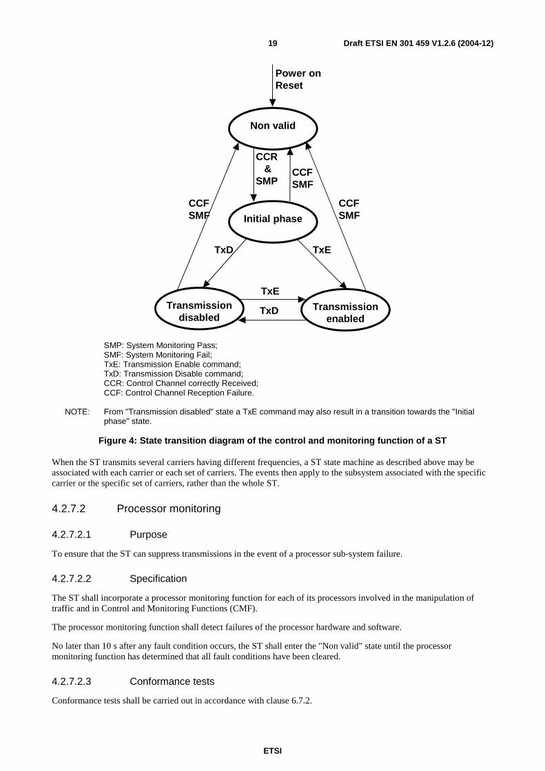
For the purpose of the present document the states of the ST are:
- "Non valid";
- "Initial phase";
- "Transmission disabled"; and
- "Transmission enabled".
In the "Non-valid" state and in the "Transmission disable" state the ST shall not transmit. In the "Transmission-enabled" state the ST is allowed to transmit. In the "Initial phase" state the ST is only allowed to transmit initial bursts.
NOTE: The restrictions in the "Initial phase" state are for the protection of other systems when the ST is entering the system after a power-on or a reset. These initial burst restrictions do not apply to the ST transmissions in the "Transmission-enabled" state and once a transmission enable command has been received by the ST, the ST may transmit at any time as required.
Under any fault condition when the ST transmissions are being suppressed the EIRP limits for the "Transmission disabled" state shall apply.
ETSI
Draft ETSI EN 301 459 V1.2.6 (2004-12) 19
TxE
Transmissiondisabled
Transmissionenabled
Non valid
Initial phase
TxD
TxE
CCR&
SMP
TxD
CCFSMF
CCFSMF
CCFSMF
Power onReset
SMP: System Monitoring Pass; SMF: System Monitoring Fail; TxE: Transmission Enable command; TxD: Transmission Disable command; CCR: Control Channel correctly Received; CCF: Control Channel Reception Failure. NOTE: From "Transmission disabled" state a TxE command may also result in a transition towards the "Initial
phase" state.
Figure 4: State transition diagram of the control and monitoring function of a ST
When the ST transmits several carriers having different frequencies, a ST state machine as described above may be associated with each carrier or each set of carriers. The events then apply to the subsystem associated with the specific carrier or the specific set of carriers, rather than the whole ST.
4.2.7.2 Processor monitoring
4.2.7.2.1 Purpose
To ensure that the ST can suppress transmissions in the event of a processor sub-system failure.
4.2.7.2.2 Specification
The ST shall incorporate a processor monitoring function for each of its processors involved in the manipulation of traffic and in Control and Monitoring Functions (CMF).
The processor monitoring function shall detect failures of the processor hardware and software.
No later than 10 s after any fault condition occurs, the ST shall enter the "Non valid" state until the processor monitoring function has determined that all fault conditions have been cleared.
4.2.7.2.3 Conformance tests
Conformance tests shall be carried out in accordance with clause 6.7.2.
ETSI
Draft ETSI EN 301 459 V1.2.6 (2004-12) 20
4.2.7.3 Transmit subsystem monitoring
4.2.7.3.1 Purpose
To ensure the inhibition of transmissions that are potentially harmful to other systems in the event of incorrect operation of the transmit frequency generation sub-system.
4.2.7.3.2 Specification
The ST shall monitor the operation of its transmit frequency generation sub-system and shall be able to detect:
1) Loss of frequency lock (if applicable);
2) Absence of Local Oscillator (LO) output signal.
No later than 1 s after any of these fault conditions of the transmit frequency generation sub-system occurs, the ST shall enter the "Non-valid" state until the transmit sub-system monitoring function has determined that all fault conditions have been cleared.
4.2.7.3.3 Conformance tests
Conformance tests shall be carried out in accordance with clause 6.7.3.
4.2.7.4 Power-on/Reset
4.2.7.4.1 Purpose
To demonstrate that the ST achieves a controlled non-transmitting state following the powering of the unit, or the occurrence of a reset made by a local operator when this function is implemented.
4.2.7.4.2 Specification
Following a manual reset, when this function is implemented, the ST shall enter the "Non-valid" state.
During and following "power-on" the ST shall remain in the "Non-valid" state.
4.2.7.4.3 Conformance tests
Conformance tests shall be carried out in accordance with clause 6.7.4.
4.2.7.5 Control Channel (CC) reception
4.2.7.5.1 Purpose
To ensure that the ST can not transmit unless it correctly receives the CC messages from the NCF.
4.2.7.5.2 Specification
a) The ST shall enter the "Non-valid" state immediately after a period not exceeding 10 s without correct reception of the CC from the NCF.
b) The ST shall remain in the "Non-valid" state as long as the CC messages from the NCF are not received.
c) From the "Non-valid" state the ST may enter the "Initial phase" state if the following conditions are met:
- the CC messages from the NCF are correctly received; and
- no fault conditions are present.
ETSI
Draft ETSI EN 301 459 V1.2.6 (2004-12) 21
4.2.7.5.3 Conformance tests
Conformance tests shall be carried out in accordance with clause 6.7.5.
4.2.7.6 Network control commands
4.2.7.6.1 Purpose
These requirements ensure that the ST is capable of:
a) retaining a unique identification in the network;
b) receiving commands from the NCF through its CC(s) and executing those commands.
4.2.7.6.2 Specification
The ST shall hold, in non-volatile memory, its unique identification code in the network.
The ST shall be capable of receiving through its CCs dedicated messages (addressed to the ST) from the NCF, and which contain:
- transmission enable commands;
- transmission disable commands.
From "Initial phase" or "Transmission enabled" states once a transmission disable command is received, within 10 s the ST shall enter into, and shall remain in, the "Transmission disabled" state until the transmission disable command is superseded by a subsequent transmission enable command.
4.2.7.6.3 Conformance test
Conformance tests shall be carried out in accordance with clause 6.7.6.
4.2.7.7 Initial burst transmission
4.2.7.7.1 Purpose
Restriction on the initial burst transmission are necessary to limit harmful interference to other services.
4.2.7.7.2 Specification
For systems where no transmission enable command is foreseen without request from the ST, in the "Initial phase" state the ST may transmit initial bursts.
a) The duty cycle of the burst retransmission shall not exceed 0,3 %.
b) Each burst shall not carry more than 256 data bytes excluding the burst preambles and the FEC coding bits.
c) The EIRP of the first initial burst after power-on or reset shall not exceed EIRPnom.
4.2.7.7.3 Conformance tests
Conformance tests shall be carried out in accordance with clause 6.7.7.
ETSI
Draft ETSI EN 301 459 V1.2.6 (2004-12) 22
5 Testing for compliance with technical requirements
5.1 Environmental conditions for testing Tests defined in the present document shall be carried out at representative points within the boundary limits of the declared operational environmental profile.
5.2 Essential radio test suites The essential radio test suites for a ST are given in clause 6.
6 Test method
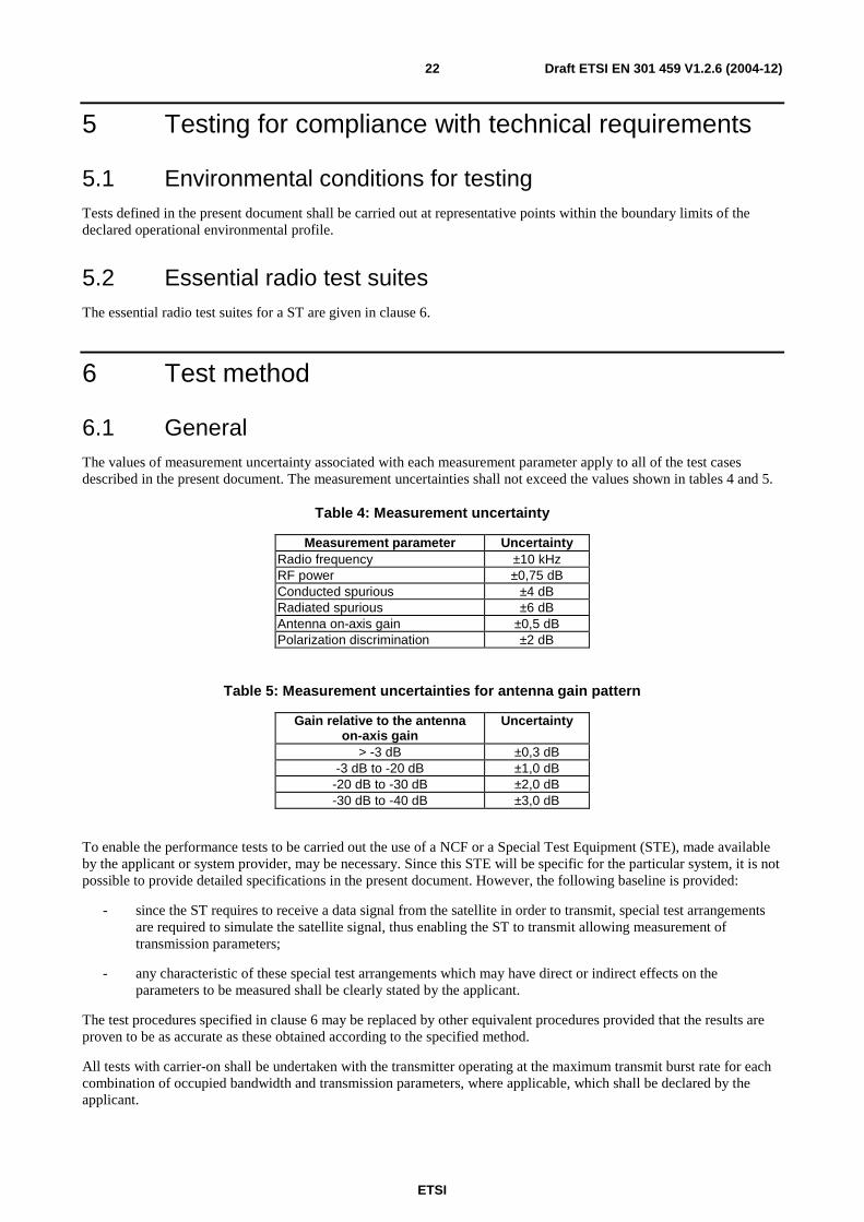
6.1 General The values of measurement uncertainty associated with each measurement parameter apply to all of the test cases described in the present document. The measurement uncertainties shall not exceed the values shown in tables 4 and 5.
Table 4: Measurement uncertainty
Measurement parameter Uncertainty Radio frequency ±10 kHz RF power ±0,75 dB Conducted spurious ±4 dB Radiated spurious ±6 dB Antenna on-axis gain ±0,5 dB Polarization discrimination ±2 dB
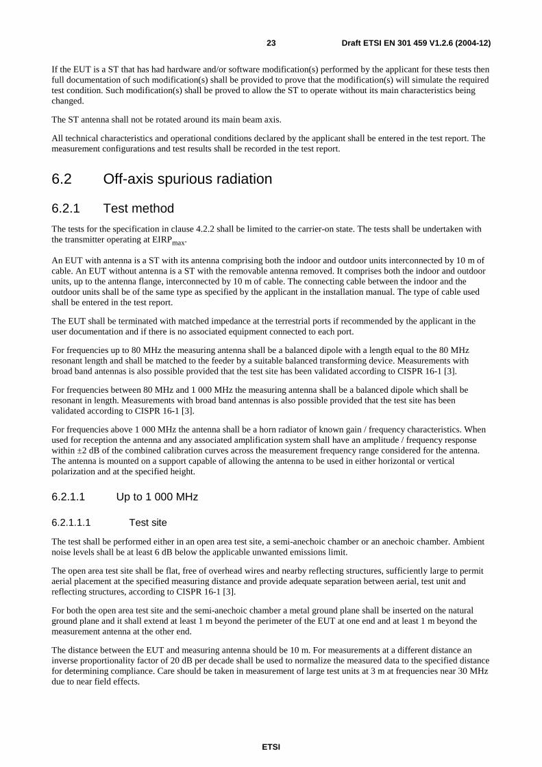
Table 5: Measurement uncertainties for antenna gain pattern
Gain relative to the antenna on-axis gain
Uncertainty
> -3 dB ±0,3 dB -3 dB to -20 dB ±1,0 dB
-20 dB to -30 dB ±2,0 dB -30 dB to -40 dB ±3,0 dB
To enable the performance tests to be carried out the use of a NCF or a Special Test Equipment (STE), made available by the applicant or system provider, may be necessary. Since this STE will be specific for the particular system, it is not possible to provide detailed specifications in the present document. However, the following baseline is provided:
- since the ST requires to receive a data signal from the satellite in order to transmit, special test arrangements are required to simulate the satellite signal, thus enabling the ST to transmit allowing measurement of transmission parameters;
- any characteristic of these special test arrangements which may have direct or indirect effects on the parameters to be measured shall be clearly stated by the applicant.
The test procedures specified in clause 6 may be replaced by other equivalent procedures provided that the results are proven to be as accurate as these obtained according to the specified method.
All tests with carrier-on shall be undertaken with the transmitter operating at the maximum transmit burst rate for each combination of occupied bandwidth and transmission parameters, where applicable, which shall be declared by the applicant.
ETSI
Draft ETSI EN 301 459 V1.2.6 (2004-12) 23
If the EUT is a ST that has had hardware and/or software modification(s) performed by the applicant for these tests then full documentation of such modification(s) shall be provided to prove that the modification(s) will simulate the required test condition. Such modification(s) shall be proved to allow the ST to operate without its main characteristics being changed.
The ST antenna shall not be rotated around its main beam axis.
All technical characteristics and operational conditions declared by the applicant shall be entered in the test report. The measurement configurations and test results shall be recorded in the test report.
6.2 Off-axis spurious radiation
6.2.1 Test method
The tests for the specification in clause 4.2.2 shall be limited to the carrier-on state. The tests shall be undertaken with the transmitter operating at EIRPmax.
An EUT with antenna is a ST with its antenna comprising both the indoor and outdoor units interconnected by 10 m of cable. An EUT without antenna is a ST with the removable antenna removed. It comprises both the indoor and outdoor units, up to the antenna flange, interconnected by 10 m of cable. The connecting cable between the indoor and the outdoor units shall be of the same type as specified by the applicant in the installation manual. The type of cable used shall be entered in the test report.
The EUT shall be terminated with matched impedance at the terrestrial ports if recommended by the applicant in the user documentation and if there is no associated equipment connected to each port.
For frequencies up to 80 MHz the measuring antenna shall be a balanced dipole with a length equal to the 80 MHz resonant length and shall be matched to the feeder by a suitable balanced transforming device. Measurements with broad band antennas is also possible provided that the test site has been validated according to CISPR 16-1 [3].
For frequencies between 80 MHz and 1 000 MHz the measuring antenna shall be a balanced dipole which shall be resonant in length. Measurements with broad band antennas is also possible provided that the test site has been validated according to CISPR 16-1 [3].
For frequencies above 1 000 MHz the antenna shall be a horn radiator of known gain / frequency characteristics. When used for reception the antenna and any associated amplification system shall have an amplitude / frequency response within ±2 dB of the combined calibration curves across the measurement frequency range considered for the antenna. The antenna is mounted on a support capable of allowing the antenna to be used in either horizontal or vertical polarization and at the specified height.
6.2.1.1 Up to 1 000 MHz
6.2.1.1.1 Test site
The test shall be performed either in an open area test site, a semi-anechoic chamber or an anechoic chamber. Ambient noise levels shall be at least 6 dB below the applicable unwanted emissions limit.
The open area test site shall be flat, free of overhead wires and nearby reflecting structures, sufficiently large to permit aerial placement at the specified measuring distance and provide adequate separation between aerial, test unit and reflecting structures, according to CISPR 16-1 [3].
For both the open area test site and the semi-anechoic chamber a metal ground plane shall be inserted on the natural ground plane and it shall extend at least 1 m beyond the perimeter of the EUT at one end and at least 1 m beyond the measurement antenna at the other end.
The distance between the EUT and measuring antenna should be 10 m. For measurements at a different distance an inverse proportionality factor of 20 dB per decade shall be used to normalize the measured data to the specified distance for determining compliance. Care should be taken in measurement of large test units at 3 m at frequencies near 30 MHz due to near field effects.
ETSI
Draft ETSI EN 301 459 V1.2.6 (2004-12) 24
6.2.1.1.2 Measuring receivers
Measuring receivers shall conform to the following characteristics:
- the response to a constant amplitude sine wave signal shall remain within ±1 dB across the frequency range of interest;
- quasi-peak detection shall be used in a -6 dB bandwidth of 120 kHz;
- the receiver shall be operated below the 1 dB compression point.
6.2.1.1.3 Procedure
a) The EUT shall be an EUT with antenna or, preferably, without antenna but with the antenna flange terminated by a dummy load.
b) The EUT shall be in the carrier-on state.
c) The EUT shall be rotated through 360° and, except in an anechoic chamber, the measuring antenna shall be rotated and height varied from 1 m to 4 m above the ground plane to determine the maximum emission.
d) All identified spurious radiation shall be measured and noted in frequency and level.
6.2.1.2 Above 1 000 MHz
The spectrum analyser resolution bandwidth shall be set to the specified measuring bandwidth or as close as possible. If the resolution bandwidth is different from the specified measuring bandwidth, bandwidth correction shall be performed for the noise-like wideband spurious.
For an EUT with antenna the tests shall be performed in two stages for both the carrier-on and carrier-off states:
- Procedure a): Identification of the significant frequencies of spurious radiation.
- Procedure b): Measurement of radiated power levels of identified spurious radiation.
For an EUT without antenna the tests shall be performed in three stages for both the carrier-on and carrier-off states:
- Procedure a): Identification of the significant frequencies of spurious radiation.
- Procedure b): Measurement of radiated power levels of identified spurious radiation.
- Procedure c): Measurement of conducted spurious radiation radiated through the antenna flange.
6.2.1.2.1 Identification of the significant frequencies of spurious radiation
6.2.1.2.1.1 Test site
The identification of frequencies emitting from the EUT shall be performed either in an anechoic chamber, an open area test site or a semi-anechoic chamber with the test antenna close to the EUT and at the same height as the volume centre of the EUT.
6.2.1.2.1.2 Procedure
a) The EUT shall be in the carrier-off state.
b) For an EUT with antenna the main beam of the antenna shall have an angle of elevation of 7°, and, for an EUT without antenna the antenna flange shall be terminated by a dummy load.
c) The receivers shall scan the frequency band while the EUT revolves.
d) The EUT shall be rotated though 360° and the frequency of any spurious signals noted for further investigation.
e) For an EUT with antenna the test shall be repeated with the test antenna being in the opposite polarization.
ETSI
Draft ETSI EN 301 459 V1.2.6 (2004-12) 25
f) The test shall be repeated in the carrier-on state while transmitting one modulated carrier at maximum power.
6.2.1.2.2 Measurement of radiated power levels of identified spurious radiation
6.2.1.2.2.1 Test site
The measurement of each spurious radiation noted during procedure a) of the test shall be performed on a test site that is free from reflecting objects, i.e. either an open-area test site, a semi-anechoic chamber or an anechoic chamber.
6.2.1.2.2.2 Procedure
EUT
Substitutionantenna
Measuring antenna
Signalgenerator
STSpectrumanalyser
Filters
Figure 5: Test arrangement - Spurious radiation measurement above 1 000 MHz for an EUT with antenna
EUT
Substitutionantenna
Measuring antenna
Signalgenerator
STSpectrumanalyser
Filters Testload
Figure 6: Test arrangement - spurious radiation measurements above 1 000 MHz for an EUT without antenna
a) The test arrangement shall be as shown in figures 5 or 6.
b) The EUT shall be installed such that the units are separated by about 1 m to 2 m with the indoor unit at a height between 0,5 m and 1,0 m on a turntable. The interconnection cable shall be supported by non-metallic means at a height between 0,5 m and 1,0 m. For the test arrangement shown in figure 5 the main beam of the antenna shall have an angle of elevation of 7° and be oriented away from the geostationary orbit, or be inhibited by placing RF absorbing panels in that direction.
ETSI
Draft ETSI EN 301 459 V1.2.6 (2004-12) 26
c) The measuring antenna shall be positioned at a distance from the EUT (e.g. 3 m, 5 m, 10 m) relevant to the applied test site. The measuring antenna shall be adjusted in height and the EUT rotated, while the EUT is in the appropriate carrier condition, for a maximum response on the associated spectrum analyser at each spurious frequency previously identified, this response level shall be noted. The adjustment in height of the measuring antenna does not apply when an anechoic chamber is being used. The measuring antenna shall never enter the 7°off-axis cone around the main beam direction.
d) The investigation shall be repeated with the measuring antenna in the opposite polarization and the response level similarly noted.
e) The EUT shall be replaced by the substitution antenna to which is connected a signal generator. The main beam axes of the measuring and substitution antennas shall be aligned. The distance between these antennas shall be the distance determined under test c).
f) The substitution and measuring antennas shall be aligned in the polarization which produced the larger response between the EUT and the test antenna in steps c) and d).
g) The output of the generator shall be adjusted so that the received level is identical to that of the previously noted largest spurious radiation.
h) The output level of the signal generator shall be noted. The EIRP of the spurious radiation is the sum, in dB, of the signal generator output plus the substitution antenna isotropic gain minus the interconnection cable loss.
6.2.1.2.3 Measurement of conducted spurious radiation at the antenna flange
6.2.1.2.3.1 Test site
There are no requirements for the test site to be used for this test.
6.2.1.2.3.2 Procedure
Spectrumanalyser
EUT Load
Notchfilter
Coupler
Figure 7: Test arrangement - conducted spurious radiation above the cut-off frequency
a) The test arrangement shall be as shown in figure 7 with the notch filter being optional. In order to protect the spectrum analyser while ensuring the necessary measurement accuracy, particularly close to the carrier, if a notch filter is used it shall be tuned to the transmit carrier frequency.
b) The frequency range from the cut-off frequency of the waveguide of the EUT to 40 GHz shall be investigated for spurious radiation while in the carrier-on state with the carrier being at maximum power and normally modulated.
c) To obtain the off-axis spurious EIRP the maximum measured antenna transmit gain, measured at the frequency of the identified unwanted emission, for off-axis angles greater than 7°, shall be added to the measured power density and any correction or calibration factors summated with the result. If agreed by the applicant, it shall be acceptable that the worst case value assumed (i.e. 8 dBi for off-axis angles greater than 7°) is used in place of the maximum off-axis antenna gain at the frequency of the identified unwanted emission.
d) The test shall be repeated in the carrier-off state.
ETSI
Draft ETSI EN 301 459 V1.2.6 (2004-12) 27
6.3 On-axis spurious radiation
6.3.1 Test method
The tests shall be undertaken with the transmitter operating at EIRPmax.
6.3.1.1 Test site
There are no requirements for the test site to be used for this test.
6.3.1.2 Method of measurement
6.3.1.2.1 General
For ST equipment for which measurements at the antenna flange are possible and agreed by the applicant, the measurements shall be performed at the antenna flange.
For ST equipment for which measurements at the antenna flange are not possible or not agreed by the applicant, the measurements shall be performed with a test antenna. The EUT is the ST with its antenna comprising both the indoor and outdoor units interconnected by 10 m of cable.
6.3.1.2.2 Method of measurement at the antenna flange
a) The test arrangement shall be as shown in figure 7 with the notch filter being optional. In order to protect the spectrum analyser while ensuring the necessary measurement accuracy, particularly close to the carrier, if a notch filter is used it shall be tuned to the transmit carrier frequency.
b) The EUT shall transmit one modulated carrier continuously, or at its maximum burst rate where applicable, centred on a frequency as close to the lower limit of the operating frequency band of the EUT as possible. The EUT shall be operated at EIRPmax. The frequency range 29,50 GHz to 30,00 GHz shall be investigated.
c) Due to the proximity of the carrier the spectrum analyser resolution bandwidth shall be set to a measurement bandwidth of 3 kHz, or as close as possible. If the measurement bandwidth is different from the specified measurement bandwidth, bandwidth correction shall be performed for noise-like wideband spurious radiation.
d) To obtain the on-axis spurious EIRP, the antenna transmit gain shall be added to any figure obtained in the above measurement and any correction or calibration factor summated with the result. The antenna gain shall be as measured in clause 6.4.1.2 at the closest frequency to the spurious frequency.
e) The tests in b) to e) shall be repeated with a transmit frequency in the centre of the operating frequency band.
f) The tests in b) to e) shall be repeated with a transmit frequency as close to the upper limit of the operating frequency band of the EUT as possible.
g) The tests in b) to f) shall be repeated in the carrier-off state.
ETSI
Draft ETSI EN 301 459 V1.2.6 (2004-12) 28
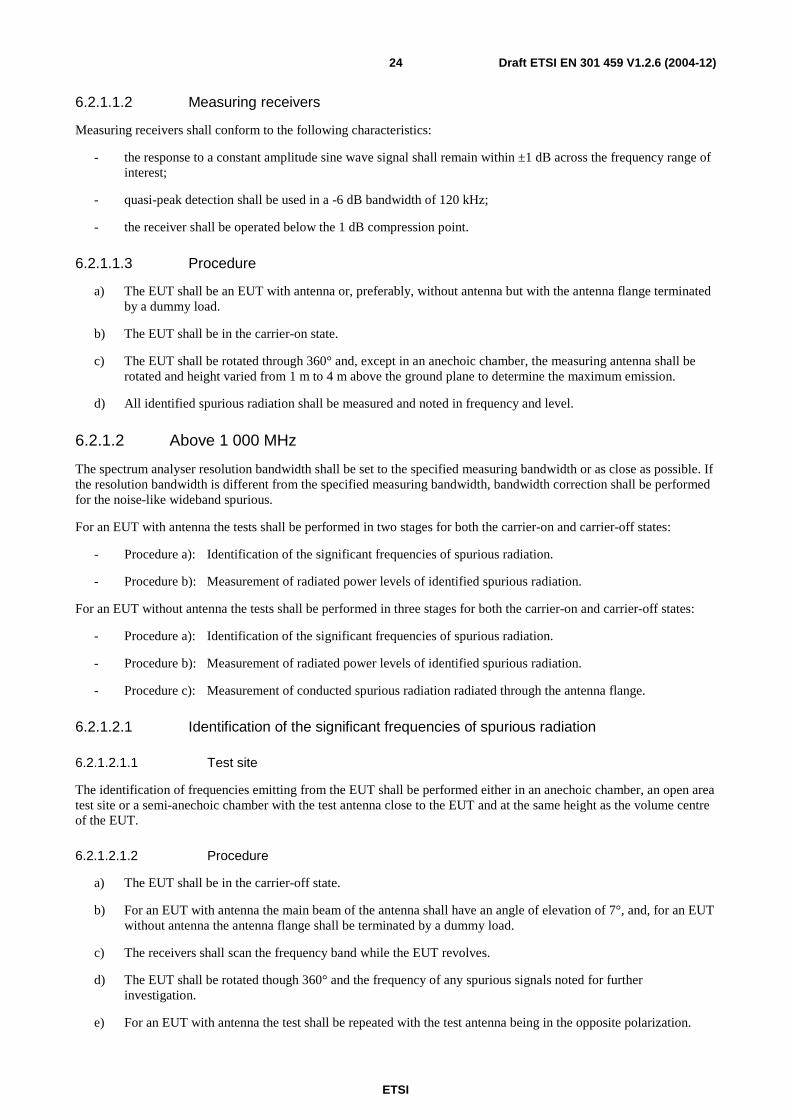
6.3.1.2.3 Method of measurement for an EUT with antenna
EUT
Substitutionantenna
Measuring antenna
Signalgenerator
STSpectrumanalyser
Filters
Figure 8: Test arrangement - on-axis spurious radiation measurements for an EUT with antenna
a) The test arrangement shall be as shown in figure 8 with the notch filter being optional.
b) The EUT shall be installed such that the units are separated by about 1 m to 2 m with the indoor unit at a height between 0,5 m and 1,0 m on a turntable. The interconnection cable shall be supported by non-metallic means at a height between 0,5 m and 1,0 m.
c) The spectrum analyser resolution bandwidth shall be set to the specified measuring bandwidth or as close as possible. If the resolution bandwidth is different from the specified measuring bandwidth, bandwidth correction shall be performed for noise-like wideband spurious radiation.
d) The EUT shall transmit one modulated carrier continuously, or at its maximum burst rate where applicable, centred on a frequency as close to the lower limit of the operating frequency band of the EUT as possible. The EUT shall be operated at EIRPmax. The frequency range 29,50 GHz to 30,00 GHz shall be investigated
and each spurious frequency shall be noted.
e) Due to the proximity of the carrier the spectrum analyser resolution bandwidth shall be set to a measurement bandwidth of 3 kHz, or lower. If the measurement bandwidth is different from the specified measurement bandwidth, bandwidth correction shall be performed for noise-like wideband spurious radiation.
f) The measuring antenna shall be positioned at a distance from the EUT (e.g. 3 m, 5 m, 10 m) relevant to the applied test site and shall be aligned with the EUT antenna for the transmit frequency. The measuring antenna shall be adjusted in height, while the EUT is in the appropriate carrier condition, for a maximum response on the associated spectrum analyser at each spurious frequency previously identified, this response level shall be noted. The adjustment in height of the measuring antenna does not apply when an anechoic chamber is being used.
g) The EUT shall be replaced by a representative substitution antenna to which a signal generator is connected. The main beam axes of the measuring and substitution antennas shall be aligned. The distance between these antennas shall be the distance determined under test f).
h) The substitution and measuring antennas shall be aligned to that polarization which produced the largest response between the EUT and the test antenna.
j) The output of the generator shall be adjusted so that the received level is identical to that of the previously noted largest spurious radiation.
k) The output level of the signal generator shall be noted. The EIRP of the on-axis spurious radiation is the sum, in dB, of the signal generator output plus the substitution antenna isotropic gain minus the interconnection cable loss.
l) The tests in d) to k) shall be repeated with a transmit frequency in the centre of the operating frequency band.
ETSI
Draft ETSI EN 301 459 V1.2.6 (2004-12) 29
m) The tests in d) to k) shall be repeated with a transmit frequency as close to the upper limit of the operating frequency band of the EUT as possible.
n) The tests in b) to m) shall be repeated in the carrier-off state.
6.4 Off-axis EIRP emission density within the band
6.4.1 Test method
The measurement shall be made in the operational configuration(s) (occupied bandwidth, EIRPnom) producing the
highest emission density in the frequency band. The selected configuration(s) shall be recorded in the test report. All of the EIRP emission density measurement shall be performed at EIRPnom.
If the test is to be carried out with an STE, then the STE shall provide all the signals needed by the STs under normal operation (e.g a radio beacon if it is expected to be received by the satellite).
For STs with uplink power density control capability the compliance of the ST with the specification of clause 4.2.4.2 during fading conditions shall be demonstrated by documentary evidence from the applicant.
The EIRP density is determined from the measurements of the antenna copolar and crosspolar gain patterns, and of the power density at the antenna flange. The EIRP density shall be compared to the specified mask, taking into account the applicant declared pointing accuracy δφ as defined in clause 4.2.6.2, if applicable.
To ascertain the off-axis EIRP it is necessary to know the transmit power density and antenna transmit radiation pattern. To ascertain the radiation pattern it is necessary to know the antenna transmit gain.
The following three measurement procedures shall be performed:
a) transmit output power density (dBW/40 kHz);
b) antenna transmit gain (dBi);
c) antenna transmit radiation patterns (dBi).
6.4.1.1 Transmit output power density
6.4.1.1.1 General
For the purpose of this test the EUT is defined as the indoor unit and that part of the outdoor unit up to the antenna flange.
The EUT output power shall be set to the power corresponding to EIRPnom.
6.4.1.1.2 Test site
There are no requirements for the test site to be used for this test.
ETSI
Draft ETSI EN 301 459 V1.2.6 (2004-12) 30
6.4.1.1.3 Method of measurement
Spectrumanalyser
EUT LoadCoupler
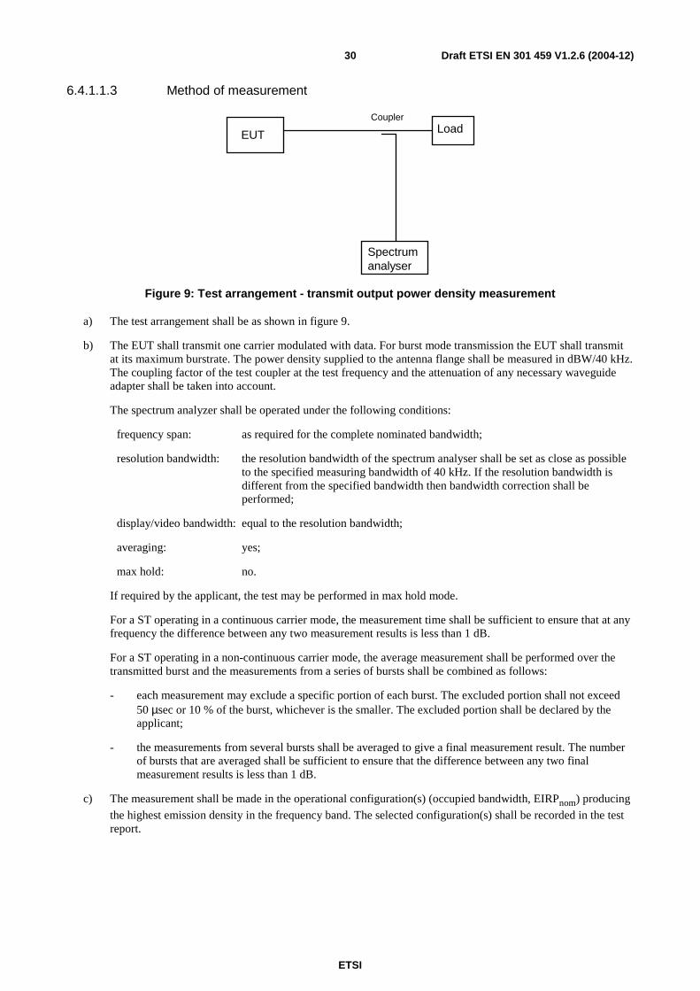
Figure 9: Test arrangement - transmit output power density measurement
a) The test arrangement shall be as shown in figure 9.
b) The EUT shall transmit one carrier modulated with data. For burst mode transmission the EUT shall transmit at its maximum burstrate. The power density supplied to the antenna flange shall be measured in dBW/40 kHz. The coupling factor of the test coupler at the test frequency and the attenuation of any necessary waveguide adapter shall be taken into account.
The spectrum analyzer shall be operated under the following conditions:
frequency span: as required for the complete nominated bandwidth;
resolution bandwidth: the resolution bandwidth of the spectrum analyser shall be set as close as possible to the specified measuring bandwidth of 40 kHz. If the resolution bandwidth is different from the specified bandwidth then bandwidth correction shall be performed;
display/video bandwidth: equal to the resolution bandwidth;
averaging: yes;
max hold: no.
If required by the applicant, the test may be performed in max hold mode.
For a ST operating in a continuous carrier mode, the measurement time shall be sufficient to ensure that at any frequency the difference between any two measurement results is less than 1 dB.
For a ST operating in a non-continuous carrier mode, the average measurement shall be performed over the transmitted burst and the measurements from a series of bursts shall be combined as follows:
- each measurement may exclude a specific portion of each burst. The excluded portion shall not exceed 50 µsec or 10 % of the burst, whichever is the smaller. The excluded portion shall be declared by the applicant;
- the measurements from several bursts shall be averaged to give a final measurement result. The number of bursts that are averaged shall be sufficient to ensure that the difference between any two final measurement results is less than 1 dB.
c) The measurement shall be made in the operational configuration(s) (occupied bandwidth, EIRPnom) producing
the highest emission density in the frequency band. The selected configuration(s) shall be recorded in the test report.
ETSI
Draft ETSI EN 301 459 V1.2.6 (2004-12) 31
6.4.1.2 Antenna transmit gain
6.4.1.2.1 General
For the purpose of the present document, the antenna transmit gain is defined as the ratio, expressed in decibels (dBi), of the power that would have to be supplied to the reference antenna, i.e. an isotropic radiator isolated in space, to the power supplied to the antenna being considered, so that they produce the same field strength at the same distance in the same direction. Unless otherwise specified the gain is for the direction of maximum radiation.
For the purpose of this test the EUT is defined as that part of the outdoor unit which comprises the antenna and its flange. The antenna may include the reflector(s), feed, support struts and an enclosure of equal weight / distribution to any electrical equipment normally housed with the feed at the antenna focal point.
6.4.1.2.2 Test site
This test shall be performed on either an outdoor far-field test site or compact test range. However, if the near-field scanner technology to convert near-field measurements to far-field results is proven and sufficiently accurate by reference to tests taken in both regions then antenna measurements may be taken in the near field. Fully automated systems can be used for these tests providing that the results can be proven to be as accurate as if they were done according to the specified method.
6.4.1.2.3 Method of measurement
Signal
generator
Test
transmitter
Testreceiver
X-YPlotter
EUT
SubstitutionAntenna
Test antenna
Figure 10: Test arrangement - antenna transmit gain measurement
a) The test arrangement shall be as shown in figure 10 with the EUT connected to the test receiver. A signal proportional to the angular position from the servo mechanism shall be applied to the X-axis and the signal level from the test receiver shall be applied to the Y-axis of the plotter.
b) A test signal at 29,750 GHz shall be transmitted by the test transmitter through the test antenna. The E-plane shall be vertical. The EUT antenna main beam axis shall be aligned with the main beam axis of the test transmitter. The polarizer of the EUT antenna shall be rotated and adjusted such that the E-plane coincides with the E-plane of the test transmitter.
c) The EUT shall be aligned to maximize the received signal and the X-Y plotter adjusted to give the maximum reading on the chart.
d) The EUT shall be driven in azimuth in one direction through 10°.
e) The pattern measurement is then obtained by driving the EUT in azimuth back through boresight to 10° the other side with the plotter recording the results.
f) The EUT shall be replaced by the substitution antenna and the received signal level maximized.
g) This level shall be recorded on the X-Y plotter.
ETSI
Draft ETSI EN 301 459 V1.2.6 (2004-12) 32
h) The substitution antenna shall be driven in azimuth as in d) and e).
j) The gain of the EUT shall be calculated from:
GEUT = L1 - L2 + C
where:
GEUT is the gain of the EUT (dBi);
L1 is the level obtained with the EUT (dB);
L2 is the level obtained with the substitution antenna (dB);
C is the calibrated gain of the substituted antenna at the test frequency (dBi).
k) The tests in c) to j) shall be repeated with the frequency changed to 29,505 GHz.
l) The tests in c) to j) shall be repeated with the frequency changed to 29,995 GHz.
m) The tests in b) to l) may be performed simultaneously.
6.4.1.3 Antenna transmit radiation patterns
6.4.1.3.1 General
For the purpose of the present document, the antenna transmit radiation patterns are diagrams relating field strength to the angle of the direction pointed by the antenna at a constant large distance from the antenna.
For the purpose of this test, the EUT is defined as that part of the outdoor unit which comprises the antenna and its flange. The antenna includes the reflector(s), feed, support struts and an enclosure of equal weight / distribution to any electrical equipment normally housed with the feed at the antenna focal point.
6.4.1.3.2 Test site
This test shall be performed on either an outdoor far-field test site or compact test range. However, if the near-field scanner technology to convert near-field measurements to far-field results is proven and sufficiently accurate by reference to tests taken in both regions then antenna measurements may be taken in the near field. Fully automated systems can be used for these tests providing that the results can be proven to be as accurate as if they were done according to the specified method.
6.4.1.3.3 Test arrangement
Signal
Generator
Test
transmitter
Testreceiver
X-Y
Plotter
EUTTest Antenna
Figure 11: Test arrangement - antenna transmit radiation pattern measurement
6.4.1.3.4 Co-polar radiation pattern - azimuth
a) The test arrangement shall be as shown in figure 11 with the EUT connected to the test receiver. A signal proportional to the angular position from the servo mechanism shall be applied to the X-axis and the signal level from the test receiver shall be applied to the Y-axis of the plotter.
b) The frequency of the test signal shall be set to 29,750 GHz.
ETSI
Draft ETSI EN 301 459 V1.2.6 (2004-12) 33
c) The initial E-plane of the test signal radiated by the test transmitter through its antenna shall be vertical for linear polarization or left hand for circular polarization antennas. The EUT antenna main beam axis shall be aligned with the main beam axis of the test transmitter. For linear polarization the polarizer of the EUT antenna shall be rotated and adjusted such that its E-plane coincides with the E-plane of the test transmitter. Precise co-polar peaking of the polarization shall be done by observing the cross-polar minimum (fine adjustment).
d) The EUT shall be aligned to maximize the received signal and the X-Y plotter adjusted to give the maximum reading on the chart.
e) The EUT shall be driven in azimuth to -180°.
f) The transmit pattern measurement is then obtained by driving the EUT in azimuth from -180° to +180° with the plotter recording the results.
g) The tests in d) to f) shall be repeated with the frequency changed to 29,505 GHz.
h) The tests in d) to f) shall be repeated with the frequency changed to 29,995 GHz.
j) The tests in b) to h) may be performed simultaneously.
k) The tests in d) to j) shall be repeated with the E-plane of the test signal being horizontal or right hand circular as appropriate. The frequency of the test signal shall be set to 29,750 GHz. For linear polarization the polarizer of the EUT antenna shall be rotated and adjusted such that its E-plane coincides with the E-plane of the test transmitter (giving the minimum cross-polar receive signal). Precise co-polar peaking of the polarization shall be done by observing the cross-polar minimum.
6.4.1.3.5 Co-polar radiation pattern - elevation
a) The test arrangement shall be as shown in figure 11 with the EUT connected to the test receiver. A signal proportional to the angular position from the servo mechanism shall be applied to the X-axis and the signal level from the test receiver shall be applied to the Y-axis of the plotter.
b) The frequency of the test signal shall be set to 29,750 GHz.
c) The initial E-plane of the test signal radiated by the test transmitter through its antenna shall be vertical for linear polarization or left-hand for circular polarization antennas. The EUT antenna main beam axis shall be aligned with the main beam axis of the test transmitter. For linear polarization the polarizer of the EUT antenna shall be rotated and adjusted such that its E-plane coincides with the E-plane of the test transmitter. Precise co-polar peaking of the polarization shall be done by observing the cross-polar minimum (fine adjustment).
d) The EUT shall be aligned to maximize the received signal and the X-Y plotter adjusted to give the maximum reading on the chart.
e) The EUT shall be driven in elevation to -1°.
f) The transmit pattern measurement is then obtained by driving the EUT in elevation from -1° to 70° with the plotter recording the results.
g) The tests in d) to f) shall be repeated with the frequency changed to 29,505 GHz.
h) The tests in d) to f) shall be repeated with the frequency changed to 29,995 GHz.
j) The tests in b) to h) may be performed simultaneously.
ETSI
Draft ETSI EN 301 459 V1.2.6 (2004-12) 34
k) The tests in d) to j) shall be repeated with the E-plane of the test signal being horizontal. The frequency of the test signal shall be set to 29,750 GHz. For linear polarization the polarizer of the EUT antenna shall be rotated and adjusted such that its E-plane coincides with the E-plane of the test transmitter. The EUT antenna main beam axis shall be aligned with the main beam axis of the test transmitter. Precise co-polar peaking of the polarization plane shall be done by observing the cross-polar minimum (fine adjustment).
6.4.1.3.6 Cross-polar radiation pattern - azimuth
a) The test arrangement shall be as shown in figure 11 with the EUT connected to the test receiver. A signal proportional to the angular position from the servo mechanism shall be applied to the X-axis and the signal level from the test receiver shall be applied to the Y-axis of the plotter.
b) The frequency of the test signal shall be set to 29,750 GHz.
c) The initial E-plane of the test signal radiated by the test transmitter through its antenna shall be vertical for linear polarization or left-hand for circular polarization antennas. The EUT antenna main beam axis shall be aligned with the main beam axis of the test transmitter. For linear polarization the polarizer of the EUT antenna shall be rotated and adjusted such that its E-plane is orthogonal to the E-plane of the test transmitter. Precise fine adjustment of the polarization plane shall be done by observing the cross-polar minimum.
d) In order to adjust the X-Y plotter giving the maximum reading on the chart the boresight co-polar receive signal shall be used.
e) The EUT shall be driven in azimuth to -10°.
f) The transmit pattern measurement is then obtained by driving the EUT in azimuth from -10° to +10° with the plotter recording the results.
g) The tests in d) to f) shall be repeated with the frequency changed to 29,505 GHz.
h) The tests in d) to f) shall be repeated with the frequency changed to 29,995 GHz.
j) The tests in b) to h) may be performed simultaneously.
k) The tests in d) to j) shall be repeated with the E-plane of the test signal being horizontal or right hand circular as appropriate. The frequency of the test signal shall be set to 29,750 GHz. The EUT antenna main beam axis shall be aligned with the main beam axis of the test transmitter. For linear polarization the polarizer of the EUT antenna shall be rotated and adjusted such that its E-plane is orthogonal with the E-plane of the test transmitter. Precise fine adjustment of the polarization plane shall be done by observing the cross-polar minimum.
a) The test arrangement shall be as shown in figure 11 with the EUT connected to the test receiver. A signal proportional to the angular position from the servo mechanism shall be applied to the X-axis and the signal level from the test receiver shall be applied to the Y-axis of the plotter.
b) The frequency of the test signal shall be set to 29,750 GHz.
c) The initial E-plane of the test signal radiated by the test transmitter through its antenna shall be vertical for linear polarization or left hand for circular polarization antennas. The EUT antenna main beam axis shall be aligned with the main beam axis of the test transmitter. For linear polarization the polarizer of the EUT antenna shall be rotated and adjusted such that its E-plane is orthogonal to the E-plane of the test transmitter. Precise fine adjustment of the polarization plane shall be done by observing the cross-polar minimum.
d) In order to adjust the X-Y plotter giving the maximum reading on the chart the boresight co-polar receive signal shall be used.
e) The EUT shall be driven in elevation to -1°.
f) The transmit pattern measurement is then obtained by driving the EUT in elevation from -1° to +10° with the plotter recording the results.
g) The tests in d) to f) shall be repeated with the frequency changed to 29,505 GHz.
ETSI
Draft ETSI EN 301 459 V1.2.6 (2004-12) 35
h) The tests in d) to f) shall be repeated with the frequency changed to 29,995 GHz.
j) The tests in b) to h) may be performed simultaneously.
k) The tests in d) to j) shall be repeated with the E-plane of the test signal being horizontal or right hand circular as appropriate. The frequency of the test signal shall be set to 29,750 GHz. The EUT antenna main beam axis shall be aligned with the main beam axis of the test transmitter. The polarizer of the EUT antenna shall be rotated and adjusted such that its E-plane is orthogonal with the E-plane of the test transmitter. Precise fine adjustment of the polarization plane shall be done by observing the cross-polar minimum.
6.4.2 Computation of results
The results shall be computed by producing a "mask" to the specified limits with the reference level being equal to the sum of the transmitter output power density and the gain of the antenna. This reference shall then be placed on the maximum point of the plots obtained from the transmit radiation pattern measurements, so as to ascertain that the off-axis EIRP density is within the mask, and thus conforming to the specification.
6.5 Carrier suppression a) The test arrangement for conducted measurements shall be as shown in figure 9. The test arrangement for
radiated measurements shall be as shown in figure 8.
b) The EUT shall transmit one modulated carrier continuously, or at its maximum burst rate where applicable, centred on 29,750 GHz.
c) The resolution bandwidth of the spectrum analyser shall be set to 100 kHz.
d) The carrier-off state shall be obtained by use of the STE.
e) For conducted measurements the maximum residual carrier power density within the nominated bandwidth shall be measured and added to the antenna on-axis gain.
f) For radiated measurements the maximum residual EIRP density within the nominated bandwidth shall be measured and recorded.
6.6 Antenna pointing for STs a) Pointing stability:
As it is considered impracticable to perform the test on pointing stability no test is given;
The test methodology described in annex A may be used to show compliance with the specification for pointing stability.
b) Pointing accuracy capability:
Specification 1: Main beam pointing accuracy
1) The EUT shall be inspected to ascertain whether fine adjustment facilities are available for the azimuth axis (coarse adjustment is usually provided by the positioning of the means of attachment).
2) The adjustment facilities shall be examined to determine both the angular movement possible and the means of securing that movement.
3) The securing facility shall be examined to determine its permanency.
4) The test shall be repeated for the elevation axis.
Specification 2: Alignment with the geostationary orbit
1) The EUT shall be inspected to ascertain whether adjustment facilities are available to align the plane or range of planes defined in clause 4.2.4.2 with the geostationary arc with the specified accuracy.
ETSI
Draft ETSI EN 301 459 V1.2.6 (2004-12) 36
2) The adjustment facilities shall be examined to determine both the angular movement possible and the means of securing that movement.
3) The securing facility shall be examined to determine its permanency.
c) Polarization angle alignment capability (linear polarization only):
1) The adjustment facilities shall be examined to determine both the angular movement possible and the means of securing that movement;
2) The securing facility shall be examined to determine its permanency.
6.7 ST Control and Monitoring Functions (CMF)
6.7.1 Test arrangement
The applicant may modify a ST for the purpose of these tests provided that full documentation is given to prove that the modifications accurately simulate the required test conditions.
The EUT shall transmit at EIRPnom.
For the purpose of these tests the EUT is the ST either with, or without its antenna connected.
The measurement of the EIRP spectral density shall be limited within either the nominated bandwidth or to a 40 MHz bandwidth centred on the carrier frequency, whichever is the greater.
STE/Load
Spectrumanalyser
Powermeter
Oscilloscope
EUTCommand
Failure
Figure 12: General test arrangement for control and monitoring tests for radiated measurements
ETSI
Draft ETSI EN 301 459 V1.2.6 (2004-12) 37
STE/LoadEUT
Spectrumanalyser
Powermeter
Oscilloscope
Command
Failure
Figure 13: General test arrangement for control and monitoring tests for conducted measurements
The test arrangement shall be as shown in figure 12 or 13. The EUT shall be authorized to transmit and shall be in the "Transmission enabled" state at the commencement of each test, unless otherwise stated. The dual trace storage oscilloscope shall monitor by measuring the time difference between the command, or failure, and the occurrence of the expected event (e.g. the transmission suppression). The spectrum analyser and the power meter shall monitor the EUT output level.
6.7.2 Processor monitoring - Test method
a) Each of the processors within the EUT shall, in turn, be caused to fail.
b) Within 10second of such failure the EUT shall cease to transmit as measured by the oscilloscope.
c) The power meter and spectrum analyser shall be observed to ascertain that the transmissions have been suppressed ("Transmission disabled" state).
d) The failed processor shall be restored to normal working condition and the EUT shall restore automatically to normal working before the next processor shall be induced to fail.
Where it is considered impracticable to artificially induce processor faults in an EUT, compliance shall be demonstrated by documentary evidence.
6.7.3 Transmit subsystem monitoring - Test method
a) The frequency generation subsystem within the EUT shall be caused to fail in respect of:
1) loss of frequency lock (if applicable);
2) absence of Local Oscillator (LO) output signal.
b) Recognition of each failure in turn by the subsystem monitor shall constitute a SMF event.
c) Within 1 s of such failure the EUT shall cease to transmit as measured by the oscilloscope.
d) The power meter and spectrum analyser shall be observed to ascertain that the transmissions have been suppressed.
e) The failed elements shall be restored to normal working state and the EUT shall be restored to normal working condition before the next induced failure.
Where it is considered impracticable to artificially induce frequency generation subsystem faults in an EUT, compliance shall be demonstrated by documentary evidence.
ETSI
Draft ETSI EN 301 459 V1.2.6 (2004-12) 38
6.7.4 Power-on/Reset - Test method
a) The EUT shall be switched off and the STE shall not transmit the CC;
b) The EUT shall be switched on;
c) The EUT shall not transmit during and after switching-on, and shall enter the "Non valid" state;
The events from a) to c) shall be displayed and verified with the oscilloscope and by measurement of the transmitted signal. If a manual reset function is implemented the following test shall be performed:
d) The EUT shall be restored to the "Initial phase" state and the STE shall transmit the CC;
e) The EUT shall remain in the "Initial phase" state;
f) The reset function shall be initiated;
g) Within 1 s the EUT shall enter the "Non valid" state;
h) The EUT shall be restored to the "Initial phase" state and the STE shall transmit the CC as well as a TxE;
i) The EUT shall enter the "Transmission enabled" state;
j) The reset function shall be initiated;
k) Within 1 s the EUT shall enter the "Non valid" state.
The event from e) to k) shall be displayed and verified with the oscilloscope and by measurement of the transmitted signal.
6.7.5 Control Channel (CC) reception - Test method
Tests shall simulate the following events:
- the CC has never been received by the EUT after power-on;
- the CC is lost by the EUT after reception of a Transmission Enable command;
- the CC is lost by the EUT without reception of a Transmission Enable command;
- the CC is being lost by the EUT and a call is initiated within the Time-Out period T1.
The Time-Out period T1 used in the tests shall be 10 s.
a) Case where the CC has never been received by the EUT after power-on:
a1) The EUT shall be switched off and the STE shall not transmit the CC;
a2) The EUT shall be switched on;
a3) The EUT shall remain in the "Non valid" state.
The events from a2) to a3) shall be displayed and verified with the oscilloscope and by measurement of the transmit signal.
b) Case where the CC is lost by the EUT after reception of a Transmission Enable command:
b1) The EUT shall be switched-on and the STE shall transmit the CC and a TxE;
b2) The EUT shall enter the "Initial phase" state and go, if applicable, to the "Transmission enabled" state;
b3) A transmission request shall be initiated from the EUT;
b4) The STE shall stop transmitting the CC;
b5) Within the period T1 from event b4), the EUT shall enter the "Non valid" state.
ETSI
Draft ETSI EN 301 459 V1.2.6 (2004-12) 39
The events from b1) to b5) shall be displayed and verified with the oscilloscope and by measurement of the transmitted signal.
c) Case where the CC is lost by the EUT without reception of a "Transmission enabled" state:
c1) The EUT shall be switched on and the STE shall transmit the CC;
c2) The EUT shall enter the "Initial phase" state;
c3) The STE shall stop transmitting the CC;
c4) The EUT shall enter in the "Non valid" state not later than T1;
c5) A transmission request shall be initiated and the EUT shall remain in the "Non valid" state.
The events from c2) to c5) shall be displayed and verified with the oscilloscope and by measurement of the transmitted signal.
d) Case where the CC is being lost by the EUT and a call is initiated within the T1 period:
d1) The EUT shall be switched on and the STE shall transmit the CC;
d2) The STE shall stop transmitting the CC;
d3) Within the period T1 from d2), a transmission request shall be initiated from the EUT;
d4) The EUT may transmit but within the T1 period the EUT shall enter the "Non valid" state.
The events from d2) to d4) shall be displayed and verified with the oscilloscope and by measurement of the transmitted signal.
6.7.6 Network Control commands - Test method
The following tests shall be performed in sequence:
- transmission enable command;
- transmission disable command received in the "Transmission enabled" state;
- transmission disable command received in the "Initial phase" state.
a) Transmission enable command:
a1) The EUT shall be switched-on and the STE shall transmit the CC;
a2) The EUT shall enter the "Initial phase" state;
a3) A transmission request shall be initiated from the EUT, the EUT shall remain in the "Initial phase" state;
a4) The STE shall transmit an enable command to the EUT;
a5) A transmission request shall be initiated from the EUT;
a6) The EUT shall enter the "Transmission enabled" state and shall transmit.
The events from a2) to a6) shall be displayed and verified with the oscilloscope and by measurement of the transmitted signal.
b) Transmission disable command received in the "Transmission enabled" state:
b1) Continue from a6);
b2) The STE shall transmit a disable command to the EUT;
b3) The EUT shall enter the "Transmission disabled" state within 1 s;
b4) A transmission request shall be initiated from the EUT;
ETSI
Draft ETSI EN 301 459 V1.2.6 (2004-12) 40
b5) The EUT shall remain in the "Transmission disabled" state;
b6) The STE shall transmit an enable command;
b7) The EUT shall enter either the "Transmission enabled" state or the "Initial phase" state;
b8) If the EUT is in the "Transmission enable" state then the test continues with b11);
b9) The STE shall transmit an TxE command;
b10) The EUT shall enter the "Transmission enable" state;
b11) If a transmission request is not active any more then a new transmission request shall be initiated;
b12) The EUT shall transmit;
b13) The EUT transmission shall be terminated;
The events from b2) to b13) shall be displayed and verified with the oscilloscope and by measurement of the transmitted signal.
c) Transmission disable command received in the "Initial phase" state:
c1) The EUT shall be switched-on and the STE shall transmit the CC;
c2) The EUT shall enter the "Initial phase" state;
c3) The STE shall transmit a disable command to the EUT;
c4) The EUT shall enter the "Transmission disabled" state within 1 s;
c5) A transmission request shall be initiated from the EUT;
c6) The EUT shall remain in the "Transmission disabled" state;
c7) The STE shall transmit an enable command;
c8) The EUT shall enter either the "Transmission enabled" state or the "Initial phase" state;
c9) If the EUT is in the "Transmission enable" state then the test continues with c12);
c10) The STE shall transmit an TxE command;
c11) The EUT shall enter the "Transmission enable" state;
c12) If a transmission request is not active any more then a new transmission request shall be initiated;
c13) The EUT shall transmit;
c14) The EUT transmission shall be terminated.
The events from c2) to c14) shall be displayed and verified with the oscilloscope and by measurement of the transmitted signal.
6.7.7 Initial burst transmission - Test method
Tests shall be performed to simulate the following events:
- the CC is being received by the EUT;
- the CC has not been received by the EUT since power-on.
a) Case where the CC is being received:
a1) The EUT shall be switched-off and the STE shall transmit the CC;
a2) The EUT shall be switched-on;
ETSI
Draft ETSI EN 301 459 V1.2.6 (2004-12) 41
a3) The EUT shall not transmit, except the initial bursts;
a4) It shall be verified that the specifications given in 5.6.2 are fulfilled.
The events from a2) to a4) shall be displayed and verified with the oscilloscope and by measurement of the transmitted signal.
b) Case where the CC has not been received by the EUT since power-on:
b1) The EUT shall be switched-off and the STE shall not transmit the CC;
b2) The EUT shall be switched-on;
b3) The EUT shall not transmit.
The events from b2) to b3) shall be displayed and verified with the oscilloscope and by measurement of the transmitted signal.
ETSI
Draft ETSI EN 301 459 V1.2.6 (2004-12) 42
Annex A (normative): The EN Requirements Table (EN-RT) Notwithstanding the provisions of the copyright clause related to the text of the present document, ETSI grants that users of the present document may freely reproduce the EN-RT proforma in this annex so that it can be used for its intended purposes and may further publish the completed EN-RT.
The EN Requirements Table (EN-RT) serves a number of purposes, as follows:
- it provides a tabular summary of all the requirements;
- it shows the status of each EN-Requirement, whether it is essential to implement in all circumstances (Mandatory), or whether the requirement is dependent on the applicant having chosen to support a particular optional service or functionality (Optional). In particular it enables the EN-Requirements associated with a particular optional service or functionality to be grouped and identified;
- when completed in respect of a particular equipment it provides a means to undertake the static assessment of conformity with the EN.
The EN-RT is placed in an annex of the EN in order that it may be photocopied and used as a proforma.
Table A.1: EN Requirements Table (EN-RT)
EN Reference EN 301 459 Comment No. Reference EN-Requirement
(note) Status
1 4.2.2 Off-axis spurious radiation M 2 4.2.3 On-axis spurious radiation M 3 4.2.4 Off-axis EIRP emission density
within the band M
4 4.2.5 Carrier suppression M 5 4.2.6 Antenna pointing accuracy M 6 4.2.7.2 Processor monitoring M 7 4.2.7.3 Transmit subsystem monitoring M 8 4.2.7.4 Power-on/Reset M 9 4.2.7.5 Control Channel (CC) reception M
10 4.2.7.6 Network control commands M 11 4.2.7.7 Initial burst transmission M
NOTE: These EN-Requirements are justified under article 3.2 of the R&TTE Directive.
Key to columns:
No Table entry number;
Reference Clause reference number of conformance requirement within the present document;
Status Status of the entry as follows:
M Mandatory, shall be implemented under all circumstances;
O Optional, may be provided, but if provided shall be implemented in accordance with the requirements;
O.n This status is used for mutually exclusive or selectable options among a set. The integer "n" shall refer to a unique group of options within the EN-RT. A footnote to the EN-RT shall explicitly state what the requirement is for each numbered group. For example, "It is mandatory to support at least one of these options", or, "It is mandatory to support exactly one of these options".
Comments To be completed as required.
ETSI
Draft ETSI EN 301 459 V1.2.6 (2004-12) 43
Annex B (informative): Pointing stability methodology This test based on a numerical analysis shall be performed in two stages.
In the first stage the effects of maximum wind speed shall be computed on the outdoor unit using a numerical analysis method (finite elements method by computer) taking into account the intrinsic properties of the materials.
In the second stage the computed loads shall be applied to the structure.
The purpose of the numerical analysis is twofold:
1) to show that the torque and the fields of force applied to the outdoor unit structure under nominated conditions do not reach the breakpoint limit of any element of the structure;
2) to compute equivalent static loads (force and torque) applied to the critical attachment points of the structures, for example:
- reflector - mounting legs fixing point;
- reflector - struts;
- LNB - struts.
Numerical analysis and load applications procedure:
1) The air related parameters, namely the kinetic viscosity used to calculate drags at the rims of the structure shall be calculated with the standard atmospheric environmental conditions (temperature = 293 K, air pressure = 1,013 x 105 Pascal).
2) The computations needed to derive the field of force and torque and the equivalent static stresses shall be carried out for each of the following variables:
- elevation angle: maximum and minimum;
- wind direction: in steps of 45° around the outdoor unit;
- wind speed: 160 km/h.
3) It shall be verified with the simulated results that break point limits are not exceeded for any self-contained element.
4) The calculated equivalent static loads shall be applied at any identified critical fixing point of the assembly.
5) While the loads are applied the outdoor unit shall be observed and any distortion noted.
6) The test report shall contain the following information:
- the computation method used;
- description of the test equipment;
- description of the tests performed;
- results of the safety margin test;
- any signs of distortion observed;
- results of the measurements of the deviation of the antenna position;
- component deviation with respect to each other.
ETSI
Draft ETSI EN 301 459 V1.2.6 (2004-12) 44
Annex C (informative): The EN title in the official languages
Language EN title Czech Danish Dutch English Estonian Finnish French German Greek Hungarian Icelandic Italian Latvian Lithuanian Maltese Polish Portuguese Slovak Slovenian Spanish Swedish
ETSI
Draft ETSI EN 301 459 V1.2.6 (2004-12) 45
Annex D (informative): Bibliography ETSI EN 300 673: "Electromagnetic compatibility and Radio spectrum matters (ERM); ElectroMagnetic Compatibility (EMC) standard for Very Small Aperture Terminal (VSAT), Satellite News Gathering (SNG), Satellite Interactive Terminals (SIT) and Satellite User Terminals (SUT) Earth Stations operated in the frequency ranges between 4 GHz and 30 GHz in the Fixed Satellite Service (FSS)".
ETSI TR 102 375: " Satellite Earth Stations and Systems (SES); Guidelines for mapping the geostationary satellite orbit protection on to satellite earth station antenna patterns".
ETSI
Draft ETSI EN 301 459 V1.2.6 (2004-12) 46
History
Document history
V1.2.1 October 2000 Publication
V1.2.6 November 2004 Public Enquiry PE 20050422: 2004-12-22 to 2005-04-22