Doc 10044 Manual on the Aeronautical Mobile Airport Communications System (AeroMACS) Disclaimer This document is an unedited version of an ICAO publication and has not yet been approved in final form. As its content may still be supplemented, removed, or otherwise modified during the editing process, ICAO shall not be responsible whatsoever for any costs or liabilities incurred as a result of its use. First Edition (advance unedited) — 2017 INTERNATIONAL CIVIL AVIATION ORGANIZATION
Transcript
Doc 10044
Manual on the Aeronautical Mobile
Airport Communications System
(AeroMACS)
Disclaimer
This document is an unedited version of an ICAO publication and has not yet been
approved in final form. As its content may still be supplemented, removed, or
otherwise modified during the editing process, ICAO shall not be responsible
whatsoever for any costs or liabilities incurred as a result of its use.
First Edition (advance unedited) — 2017
INTERNATIONAL CIVIL AVIATION ORGANIZATION
Published in separate English, Arabic, Chinese, French, Russian
and Spanish editions by the
INTERNATIONAL CIVIL AVIATION ORGANIZATION
999 Robert-Bourassa Boulevard,
Montréal, Quebec, Canada H3C 5H7
For ordering information and for a complete listing of sales agents
and booksellers, please go to the ICAO website at www.icao.int
GENERAL .................................................................................................................................................... 1-1
Figure 72. SS test setup ............................................................................................................................... A-2
Figure 73. Filter frequency response........................................................................................................... A-5
Manual on the Aeronautical Mobile Airport Communications System (AeroMACS) (xiii)
LIST OF TABLES
Table 1. Receiver sensitivity versus modulation scheme ........................................................................................ 2-13
Table 2. Maximum link loss and link budget .......................................................................................................... 2-16
Table 3. Margins for various fading considerations. ............................................................................................... 2-17
Table 4. Throughput estimates and packet size by domain. .................................................................................... 2-23
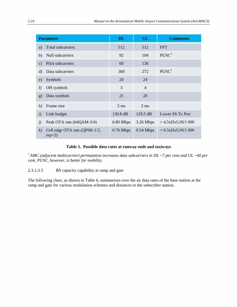
Table 5. Possible data rates at runway ends and taxiways. ..................................................................................... 2-24
Table 6. Possible data rates at ramps and gates ....................................................................................................... 2-25
Table 10. Cell types and maximum throughput ........................................................................................................ 2-41
Table 11. AeroMACS network scenarios considered and percentage of throughput dedicated to each user type ... 2-42
Table 12. Maximum number of users (per channel) - Scenario 1, DL/UL OFDM symbol rate (32, 15) .................. 2-43
Table 13. Maximum number of users (per channel) - Scenario 1, DL/UL OFDM symbol rate (26, 21) .................. 2-43
Table 14. Maximum number of users (per channel) - Scenario 2A, DL/UL OFDM symbol rate (32, 15) ............... 2-44
Table 15. Maximum number of users (per channel) - Scenario 2A, DL/UL OFDM symbol rate (26, 21) ............... 2-44
Table 16. Maximum number of users (per channel) - Scenario 2B, DL/UL OFDM symbol rate (32, 15) ............... 2-44
Table 17. Maximum number of users (per channel) - Scenario 2B, DL/UL OFDM symbol rate (26, 21) ............... 2-45
Table 18. Maximum number of users (per channel) - Scenario 3A, DL/UL OFDM symbol rate (32, 15) ............... 2-45
Table 19. Maximum number of users (per channel) - Scenario 3A, DL/UL OFDM symbol rate (26, 21) ............... 2-45
Table 20. Maximum number of users (per channel) - Scenario 3B, DL/UL OFDM symbol rate (32, 15) ............... 2-46
Table 21. Maximum number of users (per channel) - Scenario 3B, DL/UL OFDM symbol rate (26, 21) ............... 2-45
Table 26. Expected peak data rates per BS ............................................................................................................. 2-100
Table 27. Mutlicast gain possible in AeroMACS ................................................................................................... 2-101
Table 28. Options for multicast and broadcast service in AeroMACS ................................................................... 2-101
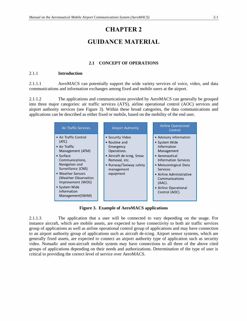
2.1.2.1.2 Most of the ATS services that are accessible at airport terminal areas may use
AeroMACS as the primary network.
2.1.2.2 Aeronautical operational control services
Generally, aeronautical operational control (AOC) services refer to a set of data link applications used to
exchange messages between aircraft and airline centres or its service partner centres on ground. AOC is
comprised of standard messages defined by AEEC standards, as well as airline defined proprietary
messages.
2.1.2.3 Airport authority services
Generally, the airport authority services refers to a set of applications that is used to operate and control
the airport. Information on the status of runways, facilities, airport security, etc. is generally considered
under this category. Systems and services identified at the time of writing include:
a) FOD debris detection systems;
b) airfield lighting systems;
c) radar, e.g. avian radar;
d) NAVAIDs;
e) runway incursion prevention systems;
f) wildlife detection systems;
2-4 Manual on the Aeronautical Mobile Airport Communications System (AeroMACS)
g) runway condition reporting systems;
h) in-pavement condition reporting systems;
i) perimeter surveillance;
j) intruder detection;
k) airfield access control systems;
l) audio/video communication with the ground vehicles; and
m) audio/video communication with emergency vehicles.
2.1.3 Aircraft operational scenario
2.1.3.1 Description
2.1.3.1.1 Aircraft operations at airport terminal areas can be classified under three major scenarios
namely:
a) aircraft landing;
b) aircraft parked; and
c) aircraft departure.
2.1.3.1.2 Aircraft operations at hangers can be considered similar to aircraft on the apron scenario
in the context of the AeroMACS network.
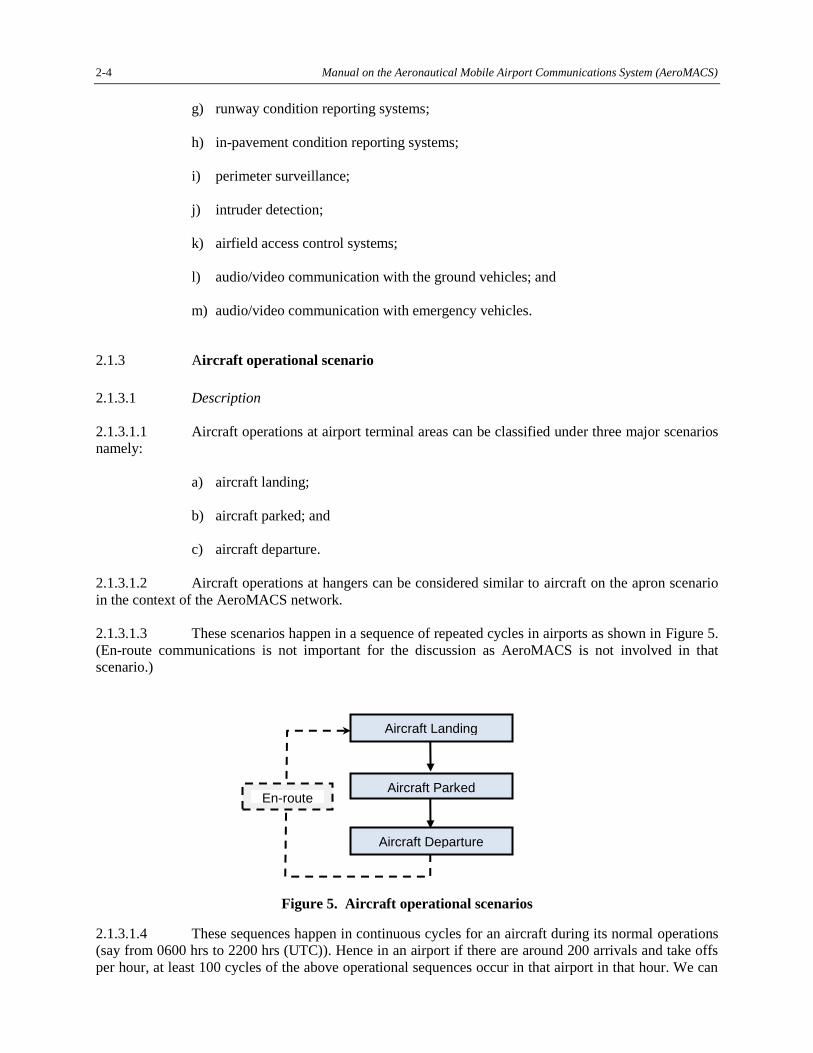
2.1.3.1.3 These scenarios happen in a sequence of repeated cycles in airports as shown in Figure 5.
(En-route communications is not important for the discussion as AeroMACS is not involved in that
scenario.)
Figure 5. Aircraft operational scenarios
2.1.3.1.4 These sequences happen in continuous cycles for an aircraft during its normal operations
(say from 0600 hrs to 2200 hrs (UTC)). Hence in an airport if there are around 200 arrivals and take offs
per hour, at least 100 cycles of the above operational sequences occur in that airport in that hour. We can
Aircraft Landing
Aircraft Parked
Aircraft Departure
En-route
Manual on the Aeronautical Mobile Airport Communications System (AeroMACS) 2-5
assume a halting period of eight hours per overnight stay for an aircraft at airports. The individual
scenarios are expanded in the following subsections. 2.1.3.2 Aircraft landing
2.1.3.2.1 The aircraft landing scenario refers to the operations performed by an aircraft from its
touchdown to taxiing till gate. On touchdown, the aircraft establishes data link connectivity with the
airport network. (The airport network is based on AeroMACS service.) The services that the aircraft is
likely to be connected to are as follows:
a) D-TAXI (data link – taxi) route plan is uploaded to aircraft. (ATC);
b) OOOI (off/out/on/in) status is provided. (AOC);
c) ACM (ATC communications management) transfer of control happens from runway
tower to ground tower. (ATC);
d) A-SMGCS (advanced surface movement guidance and control system) surface
services are activated in addition to surface surveillance information being provided
to aircraft. (ATC);
e) TAXI clearances are provided. (ATC-ground tower); and
f) flight data is downloaded to airline operations/maintenance centres. (AOC).
2.1.3.3 Aircraft parked
2.1.3.3.1 The aircraft parked scenario refers to the operation performed when an aircraft is parked
at the gates, its engines are switched off and some upkeep operations are being performed. In this scenario,
aircraft will be connected to airport, ANSP and airline private networks while exchanging data through
the AeroMACS access network. The services that an aircraft is likely to be connected to are as follows:
a) avionics software and database are uploaded. These databases include airport
information, navigational data, pilot manuals, terrain data etc.;
b) maintenance data from avionics/engine are downloaded if not downloaded during the
aircraft landing above. This data may include both prognostics and diagnostics
information;
c) pilot manuals/charts/maps etc., may be uploaded;
d) electronic checklist/electronic flight bag (EFB) updates; and
e) routine maintenance checks.
2.1.3.4 Aircraft departure
2.1.3.4.1 In aircraft departure scenario, all operations from pre-departure phase to take-off phase
are covered. Aircraft pushes back from the gate, starts engines, taxies to the runway and then takes off
Aircraft remain connected to the AeroMACS network until its take-off. The services that the aircraft is
likely to be connected to are as follows:
a) flight planning and support services;
2-6 Manual on the Aeronautical Mobile Airport Communications System (AeroMACS)
b) airport terminal information messages (ATIS),which provides information about the
availability of active runways, approaches, weather conditions, NOTAMS, etc.;
c) departure clearance;
d) runway visual range information;
e) hazardous weather and operational terminal information;
f) weight and balance information flight preparations, delays, pilot preferences;
g) OOOI messages; D-TAXI/Push back clearances;
h) TAXI route information and instructions surface surveillance guidance control; and
i) ACM messages or any other information related to the regularity and safety of flight.
2.1.3.4.2 During the take-off phase the aircraft will disconnect from AeroMACS.
2.1.3.5 Typical scenarios
2.1.3.5.1 This section describes typical scenarios for the use of the AeroMACS communications
system. Within this document, the use of other communications systems such as Mode S and universal
access transceiver (UAT) for automatic dependent surveillance-broadcast (ADS-B) messaging and VDL
Mode 2 for controller pilot data link communications (CPDLC) is discussed in addition to the use of
AeroMACS. This further shows the context in which AeroMACS is intended to be used.
Note.― The following operational scenarios mention a broad range of applications/services.
Many States may only operate a subset of these especially when AeroMACS service is introduced.
2.1.3.5.2 The aircraft operator provides gate/stand/hangar information, aircraft registration/flight
identification and estimated off-block time to other users (e.g. airport, fixed base operation, corporate
operation and ATC) via the ground-ground communications system. The flight crew prepares the aircraft
for the flight and, in particular, provides the necessary inputs and checks with the flight management
system (FMS). Among their other duties, the pilots power up the aircraft communications systems which
include the AeroMACS communications system. The pilots connect their electronic flight bag (EFB) to
the communications system ports in the aircraft provided for EFBs to enable updates to all EFB
applications. As the various data communications connections are being established, the pilots are
performing other duties to prepare the aircraft for the flight. The pilots initiate air traffic control (ATC)
voice link and CPDLC to enable transfer of ATC clearances. The flight crew requests the flight plan from
aircraft operational control (AOC) for airlines or flight operational control (FOC) for business aviation
and enters the provided flight plan data into the FMS. The aircraft begins receiving supporting data from
SWIM services via AeroMACS to support trajectory negotiation and other SWIM services
(e.g. NOTAMS, PIREPS, AWAS).
2.1.3.5.2 The pilot requests D-ATIS information and receives the response via the AeroMACS
system. The flight crew consults relevant aeronautical information services (e.g. planning information
bulletins, notices to airmen (NOTAMs), and aeronautical information charts) concerning the flight.
Real-time information on the flight’s departure is now available in the air traffic services unit (ATSU)
automation system. The flight information service (FIS) system response provides all relevant
information for the weather, automatic terminal information service (ATIS), and field conditions, plus the
Manual on the Aeronautical Mobile Airport Communications System (AeroMACS) 2-7
local NOTAMs. The pilots review updated information for appropriate adjustment to information entered
in aircraft systems such as the FMS and for coordination with ATC and AOC/FOC.
2.1.3.5.3 The aircraft begins receiving surface vehicle locations on the ADS-B/traffic information
system-broadcast (TIS-B) system in the aircraft. Some of the vehicles on the airport surface are equipped
with an AeroMACS ADS squitter message (typically non-movement area vehicles such as people movers,
tugs, food trucks, baggage carts) while others are equipped with ADS-B squitter message (usually
movement area vehicles such as snow plows, fire engines, maintenance vehicles) using Mode S or UAT.
Both squitter types of information are transferred to the TIS-B surveillance system. The processed data
from the TIS-B surveillance system is transferred to both aircraft and vehicles systems and service
organizations (such as airlines, airport authorities, fuel truck companies, fixed base operators (FBOs),
and handling organizations) as appropriate for their usage. For aircraft preparing to taxi, the current
graphical picture of the ground operational environment is uplinked and loaded using the standard
ADS-B/TIS-B links to the aircraft. Some aircraft begin squittering position via the AeroMACS system, as
the Mode S system is not yet powered up due to certain aircraft implementation issues (high power
transmissions of weather radar which cause personnel safety issues are enabled by the same power switch
as the Mode S system on some aircraft).
2.1.3.5.4 The load sheet request is sent to AOC. The load sheet response with the “dangerous
goods notification information” and the last minute changes to the weight and balance of the aircraft are
sent by the AOC and are automatically loaded into the avionics. The flight crew requests a “start up and
push back clearance” via the data link taxi service. The flight crew pushes back and starts up the engines
in accordance with airport procedures. The push back sends an “out-off-on-in (OOOI)” message to AOC
advising that the flight has left the gate/stand.
2.1.3.5.5 The tug is attached to the aircraft and the tug operator communicates with the pilots using
VoIP via AeroMACS to coordinate the pushback of the aircraft. The pilots receive
clearance/authorization to push-back and proceed on this snowy day to the de-icing station. As the aircraft
pushes back, the surveillance service is activated and continues for the duration of the flight to the
destination gate.
2.1.3.5.6 The pilots are aware of the tug position on this snowy day via both visual and TIS-B
broadcasts as the tug is squittering its position as are all other vehicles on the surface of the airport (both
movement and non-movement areas). As the aircraft approaches the de-icing station, coordination occurs
over the AeroMACS VoIP with personnel at the de-icing station. As the de-icing procedure is occurring,
the pilots request updated D-ATIS information for review and possible action. Having completed the
de-icing procedures, the aircraft receives clearance to proceed to the runway. On the way to the runway,
the aircraft passengers and crew prep for take-off. As part of the prep for take-off the pilots stow the EFB.
The aircraft is given clearance to take-off. As the aircraft takes off, an out-off-on-in message is generated
and sent (or stored for transmission) to AOC that the aircraft is airborne. The aircraft AeroMACS system
discontinues transmission starting at take-off while other communications and surveillance systems such
as VDL Mode 2 and ADS-B are fully operational.
2.1.3.5.7 As the aircraft proceeds towards its destination, the aircraft collects aircraft engine data
and other aircraft information for later transmission. The decision to use the AeroMACS system when
reconnected rather than an alternative link during the flight will be due to the aircraft owner policy based
on link costs or a need to protect proprietary data. For example, D-ATIS requests for the next leg of the
flight (that do not require responses while in the air) could also be held back for communications over the
AeroMACS system.
2.1.3.5.8 The flight crew lands the aircraft. After the aircraft lands, the AeroMACS system quickly
connects and the stored data and requests are automatically transmitted over the AeroMACS system.
2-8 Manual on the Aeronautical Mobile Airport Communications System (AeroMACS)
Responses to requests are made available to the requestors. As the avionics detects touchdown the aircraft
sends the on-OOOI information to the AOC. As the aircraft proceeds across the airport surface, aircraft
ADS-B transmissions are received by the ADS-B ground station at the airport. The ADS-B transmissions
received from the aircraft are forwarded to the TIS-B servers via AeroMACS as some of the ground
stations do not have direct access to the airport LAN to enable transfer ADS-B squitter information
between the TIS-B servers and the ground stations. In addition the multilateration system that tracks
aircraft position on the surface of the airport connects via the AeroMACS system to the ATC service
provider surveillance system to provide the multilateration sensor data.
2.1.3.5.9 When the aircraft arrives at the gate/stand, the aircraft sends the in-OOOI message to
AOC which makes the information available for other users. AOC responds to the OOOI message with a
flight log transfer message to inform the crew of the next flight assignment.
2.1.3.6 Applications supported
AeroMACS is agnostic to the applications supported, however, message routing and handling will be
determined based on the particular applications in the operational scenarios just described. Later sections
on routing and discovery and service flows will be discussed in detail.
2.1.4 Routing and discovery
2.1.4.1 The aeronautical communication network comprises multiple independent networks with
separate administrative domains interconnected to each other to achieve the overall safety communication
infrastructure. Examples of such networks are; air navigation service provider (ANSP) network, airlines
network, airport service provider network, OEM network, etc. These networks would be predominantly
based on ATN/IPS (IPv6). These are closed networks that are protected against intrusion from the public
internet. Hence, the overall aeronautical network can be imagined as islands of closed networks
interconnected over public infrastructure to form a closed internet for aeronautical purposes. See Figure 6.
Manual on the Aeronautical Mobile Airport Communications System (AeroMACS) 2-9
Figure 6. Aeronautical network
2.1.4.2 As per the recommendations of the Manual on the Aeronautical Telecommunication
Network (ATN) using Internet Protocol Suite (IPS) Standards and Protocols (Doc 9896), independent
autonomous networks are to be interconnected using inter-domain routers (such as BGP). To maintain
abstraction with the public internet, these routers are not exposed to other routers in public domains.
Secured links, either based on VPNs or dedicated telecom lines are deployed to interconnect the routers
belonging to the aeronautical network. The ingress and egress to safety networks are controlled by routers
to ensure complete abstraction from the internet.
2.1.4.3 AeroMACS acts as an access network for the airport domain as shown in the Figure 6.
Hence, the AeroMACS ASN Gateway is connected to the core router in the airport domain network. The
airport network may obtain its address space from an approved registry such as ICAO or the Internet
Assigned Numbers Authority (IANA) and allocates those addresses to its internal networks. For example:
if an airport network covers ten different airports, the airport network operator obtains a consolidated
address space and suballocates them to the ten airports. Subsequently, each of the airports allocates
addresses to its internal network elements. The network edge router advertises the consolidated address
space to the external routers.
2.1.4.4 Aircraft may have either global permanent IP addresses allocated to it or may obtain a
temporary IP address from the access network at the point of contact. For instance, in case of IPv4
deployment it may not be possible to obtain a permanent global address for aircraft owing to IPv4 address
scarcity. However, in case of IPv6, aircraft may be assigned permanent addresses. Depending upon such
address allocation schemes, the routing and discovery mechanisms would differ at deployments. In case
of temporary IP addresses allocated by the access network, IP mobility implementations such as mobile
IP (MIP), proxy mobile IP (PMIP) or any other state of art IP mobile technology may be deployed. In
2-10 Manual on the Aeronautical Mobile Airport Communications System (AeroMACS)
case of permanent global IP addresses allocated to an aircraft, the aircraft may become an independent
autonomous network. In such a scenario, the aircraft may need to have an inter-domain router that
connects it to the edge router in the airport network.
2.1.4.5 The routing and mobility concepts are not completely finalized for IPS network.
However, these implementations are outside the scope of AeroMACS (access) network. At a minimum,
the access network is expected to support both static and dynamic addressing schemes at the link interface
for an aircraft.
2.2 FREQUENCY ALLOCATION AND CHANNELIZATION
2.2.1 AeroMACS operates in frequency bands internationally allocated per the aeronautical
mobile (route) service (AM(R)S). As a result, AeroMACS, in the internationally allocated bands, is
restricted to supporting communications related to safety and regularity of flight. In addition, in
accordance with International Telecommunications Union (ITU) Radio Regulations, AeroMACS is
limited to supporting surface transmissions at airports.
2.2.2 In general, AM(R)S bands are intended to provide communications between aircraft and
ground stations or between aircraft. However, ITU does not preclude operations in frequency bands
allocated to a mobile service (like AM(R)S) to support both mobile and fixed/nomadic (i.e. low mobility)
applications. As a result, some States plan to utilize AeroMACS also for airport surface communications
between ground stations. Finally, some States allow limited use of AM(R)S frequency bands (and by
extension AeroMACS) by non-aircraft vehicles; in particular vehicles such as snow ploughs which may
mix with aircraft on the airport movement area.
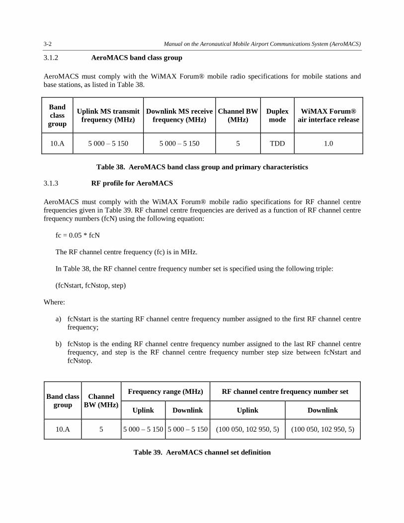
2.2.3 AeroMACS equipment can tune across the band 5 000 MHz to 5 150 MHz, in 250 kHz
steps with reference channel of 5 145 MHz. That reference channel is used to identify a channel whose
centre frequency is among the centre frequencies that are to be tuned by AeroMACS and it is a reference
point for the identification of all other centre frequencies that may be tuned by AeroMACS using the
channel step size. The 250 kHz step size will allow AeroMACS to gracefully move away from any
interference source such as microwave landing systems (MLS), aeronautical mobile telemetry (AMT), or
military users operating in the 5 000 to 5 150 MHz band.
2.2.4 The core or primary AeroMACS band is 5 091 to 5 150 MHz, however, channels can also
be assigned in the subbands 5 000 to 5 030 MHz, based on national regulations, and 5 030 to 5 091 MHz
depending on frequency planning defined at the ICAO level considering other aeronautical applications.
2.2.5 Due to its limitation to surface transmissions, it is expected that in most cases all
AeroMACS channels will be available at all airports (i.e. airport-to-airport coordination is not expected to
be necessary). It is also expected, however, that not all airports will have sufficient communications
requirements to necessitate use of all the AeroMACS channels.
2.2.6 One constraint on AeroMACS that was considered during the development of the
AeroMACS Standards is ensuring compatibility with satellites that share the same operating frequency
band. While those Standards were developed using worst-case assumptions, compatibility with the
satellites can be enhanced by, for airports which do not require use of all the channels, distributing
actually assigned channels across the band. In order to ensure uniformity in that distribution, it is expected
that a central authority in each State will control AeroMACS assignments.
2.2.7 To operate an AeroMACS system at an aerodrome, a spectrum license will be required.
Spectrum regulations should be well documented prior to any considerations on siting. Any special
Manual on the Aeronautical Mobile Airport Communications System (AeroMACS) 2-11
permissions when needed, should be investigated. Operators should be aware of any limitations
(municipal, State and federal or military) to the use of certain frequency channels.
2.2.8 Further detail on AeroMACS channel assignment criteria and constraints are under
development by ICAO. When completed they will be included in Annex 10, Volume V.
2.2.9 AeroMACS is for communication on the airport surface only. Although aircraft on the
approach and departure phase of the flight may receive AeroMACS signals while on flight as shown by
the glide slopes in Figure 7, aircraft are not permitted to transmit on AeroMACS bands while in flight.
Airport systems should be designed to reduce sky-ward emissions through appropriate placement and
orientation of the AeroMACS antennas.
Figure 7. AeroMACS operational environment
2.3 SITING
2.3.1 Base station siting criteria
2.3.1.1 Siting is the process in determining the desirable locations of AeroMACS base station
equipment on the airport surface. Siting incorporates a number of considerations and the conclusion of the
process is a specification of base station locations, antenna locations, tilt angle and height. Siting takes
into account the following:
a) the AeroMACS network architecture such as the physical devices to be deployed;
b) equipment performance such as transmit power, capacity and antenna gain;
c) service requirements such as coverage area and bandwidth;
d) requisite infrastructures such as power and data network points of presence (POPs);
e) buildings and terrain that interfere with line of sight requirements;
f) airport restrictions including no-obstruction areas;
g) airport infrastructures such as landing systems that cannot accept physical or
electrical interference;
2-12 Manual on the Aeronautical Mobile Airport Communications System (AeroMACS)
h) physical access requirements for maintenance; and
i) people and equipment movement.
2.3.1.1.1 An AeroMACS cell network involves BSs and SSs. This document considers the
identification of desirable locations for BS. SS locations are not part of the siting analysis but they are
implicitly included since a proper BS siting can give service to a number of SS in the coverage area with
the expected required performance. In any case, the coverage depends on the link budget between BS and
SS, the latter being a mobile device or a fixed station that has been purposely located within the coverage
range of a BS part of the siting exercise.
2.3.1.1.2 There is no optimum solution for equipment location. The considerations for siting
ultimately result in a compromise that simultaneously meets the network performance objectives and all
the other requirements and limitations that are imposed. This section leads the reader through the process
of siting, introduces the relevant considerations and lends guidance to the decisions and trade-offs that
determine a useful specification of equipment location to meet all the requirements of the AeroMACS
network.
2.3.1.2 Characteristics pertinent to site selection
AeroMACS MS will be subject to multiple BS to BS handovers. AeroMACS connections must be
maintained throughout the airport surface for aircraft ground velocity up to 50 knots (~58 mph). Aircraft
network connections in runway, taxiway, ramp and gate areas will be subject to fast fading due to
multipath fluctuations of moving aircraft and ground vehicles. While many AeroMACS network
connections will be line of sight connections, design considerations must be made for non-line of sight
connections for ground handling equipment with lower antenna elevations or sensors placed on the
ground, for example.
2.3.1.2.1 Antenna coverage
2.3.1.2.1.1 Base station antennas are typically directional with gain and a characteristic antenna
pattern or beamwidth of gain versus elevation and azimuth. Smaller airports may benefit from
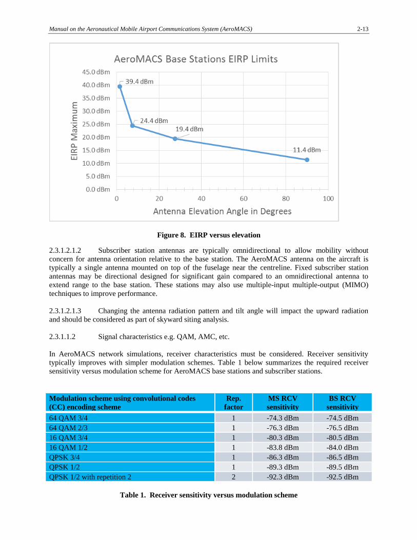
omnidirectional antenna choices for the base station. Figure 8 establishes AeroMACS limits for EIRP
versus elevation for the base station and antenna that antenna choice and tilt orientation must consider.
These results were used to validate that AeroMACS global deployments would not violate the ITU
WRC-07 requirements of the 2 degree temperature rise at the satellite.
Manual on the Aeronautical Mobile Airport Communications System (AeroMACS) 2-13
Figure 8. EIRP versus elevation
2.3.1.2.1.2 Subscriber station antennas are typically omnidirectional to allow mobility without
concern for antenna orientation relative to the base station. The AeroMACS antenna on the aircraft is
typically a single antenna mounted on top of the fuselage near the centreline. Fixed subscriber station
antennas may be directional designed for significant gain compared to an omnidirectional antenna to
extend range to the base station. These stations may also use multiple-input multiple-output (MIMO)
techniques to improve performance.
2.3.1.2.1.3 Changing the antenna radiation pattern and tilt angle will impact the upward radiation
and should be considered as part of skyward siting analysis.
2.3.1.1.2 Signal characteristics e.g. QAM, AMC, etc.
In AeroMACS network simulations, receiver characteristics must be considered. Receiver sensitivity
typically improves with simpler modulation schemes. Table 1 below summarizes the required receiver
sensitivity versus modulation scheme for AeroMACS base stations and subscriber stations.
Modulation scheme using convolutional codes
(CC) encoding scheme
Rep.
factor
MS RCV
sensitivity
BS RCV
sensitivity
64 QAM 3/4 1 -74.3 dBm -74.5 dBm
64 QAM 2/3 1 -76.3 dBm -76.5 dBm
16 QAM 3/4 1 -80.3 dBm -80.5 dBm
16 QAM 1/2 1 -83.8 dBm -84.0 dBm
QPSK 3/4 1 -86.3 dBm -86.5 dBm
QPSK 1/2 1 -89.3 dBm -89.5 dBm
QPSK 1/2 with repetition 2 2 -92.3 dBm -92.5 dBm
Table 1. Receiver sensitivity versus modulation scheme
2-14 Manual on the Aeronautical Mobile Airport Communications System (AeroMACS)
2.3.1.1.3 Coverage and capacity consideration
This section describes coverage and capacity factors to consider for the airport area being served.
AeroMACS service areas include runways, taxiways, ramp areas, maintenance areas, the respective
transition points and other special use areas on the airport surface to potentially encompass the entire
outdoor airport surface in many instances.
2.3.1.1.3.1 Fixed applications Fixed applications focus on wireless connectivity for priority standalone applications for “islands” of
dedicated network coverage on the airport surface. Fixed applications may or may not share AeroMACS
network infrastructure depending on network owner and operation considerations, priority and safety
considerations, and deployment timeline considerations. Multilaterlation (MLAT), weather observation
(WOI) and video surveillance for security and safety enhancements are examples of fixed applications.
Site surveys and radio frequency (RF) planning should minimize the need to re-locate base stations in the
future as AeroMACS applications evolve. Some initial base station deployments could be
“easily-moveable” or “nomadic” to accommodate unanticipated future AeroMACS application rollout.
2.3.1.1.3.2 Runway/taxiway areas The service coverage objective is to provide connectivity anywhere and anytime on the airport surface for
AeroMACS-equipped aircraft or ground vehicles.
2.3.1.1.3.3 Ramp and gate areas
Gate spacing is typically determined by the wing spans of aircraft. Gate spacing of 80 to 120 meters is a
reasonable estimate for airports that serve large jet aircraft. AeroMACS sector range of 1 km will cover
eight to twelve gates with an excess loss factor, n = 4. For the capacity discussions that follow, capacity
estimates assume eight gates/BS channel with all gates occupied by aircraft, or 8 aircraft per channel.
Data payload requirements per aircraft include requirements for necessary support equipment including
fuelling and baggage handling equipment, for example. Further, one-half hour is assumed for available
time to deliver the required DL data payload per aircraft and to receive the required UL data payload per
aircraft and a tentative 67 per cent/33per cent DL to UL payload ratio is incorporated into the data
models.
2.3.1.1.3.4 Maintenance and fixed base operators (FBOs) Maintenance and FBO areas typically serve airline specific operations. High traffic exchanges are
expected (GBytes) for EFB updates, software uploads, electronic charts, log downloads and other
transactions. These data transactions may happen over long periods of time from hours to overnight.
2.3.1.1.3.5 Airport obstructions and terrain
Airport obstructions, terrain impact and fresnel zone must be identified and anticipated in the system
engineering performed for the AeroMACS network plan.
Manual on the Aeronautical Mobile Airport Communications System (AeroMACS) 2-15
2.3.1.1.3.6 Aircraft and vehicle types Aircraft and vehicle types must be identified and anticipated in the system engineering performed for the
AeroMACS network plan. This is important for SS antennas that are low off the ground.
2.3.1.1.3.7 Types of SS devices The types of subscriber station devices must be identified and anticipated in the system engineering
performed for the AeroMACS network plan. SS devices may include fixed stations and mobile stations
with significantly different form factors including PCMCIA cards, PDAs and notebooks/tablet PCs,
handheld devices and aircraft radios.
2.3.1.2 Coverage capabilities
This section illustrates the propagation models used for different airport locations for both BS and SS to
aid in the analytical evaluation. Information for computation and simulation is also provided in this
section.
2.3.1.2.1 Link budget
2.3.1.2.1.1 The link budget first calculates maximum allowable link loss by taking into account
factors such as transmitter power, receiver sensitivity, antenna gain, cable loss, noise figure, noise floor,
modulation scheme and other factors. The link loss is adjusted for fade margin and other margin
adjustments to arrive at a link budget. The link budget is an estimate that the system engineer should
verify by measurements performed on-site.
2.3.1.2.1.2 The following charts, as shown in Tables 2 and 3, determine the maximum link loss and
link budget for an AeroMACS system.
2-16 Manual on the Aeronautical Mobile Airport Communications System (AeroMACS)
2.4.4.4. In order to calculate the throughput limitations in a BS, the modulation/coding rate and
the DL/UL OFDM symbol ratio needs to be derived. Table 8 of the AeroMACS MASPS shows the
application data rate (TCP/IP PDU throughput) in a BS depending on the modulation/coding scheme used.
Note that these results were obtained by applying (32, 15) DL/UL OFDM symbol rate. The rate (26, 21)
is also considered in this study as the most symmetrical DL/UL configuration mandated in the
AeroMACS profile. The throughput resulting from this configuration is approximated in Table 9.
1 Using median (50th percentile) is recommended for capacity estimations. Average can lead to wrong conclusion if the traffic
demand is not distributed uniformly over time. 2 “Peak” refers to 95th percentile. 3 Aircraft data requirements in line with MASPS. 4 Video works at 360p at 24 FPS and supports compression in low image refresh periods.
Manual on the Aeronautical Mobile Airport Communications System (AeroMACS) 2-41
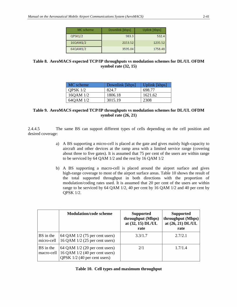
Table 8. AeroMACS expected TCP/IP throughputs vs modulation schemes for DL/UL OFDM
symbol rate (32, 15)
MC scheme Downlink [kbps] Uplink [kbps]
QPSK 1/2 824.7 698.77
16QAM 1/2 1806.18 1621.62
64QAM 1/2 3015.19 2308
Table 9. AeroMACS expected TCP/IP throughputs vs modulation schemes for DL/UL OFDM
symbol rate (26, 21)
2.4.4.5 The same BS can support different types of cells depending on the cell position and
desired coverage:
a) A BS supporting a micro-cell is placed at the gate and gives mainly high-capacity to
aircraft and other devices at the ramp area with a limited service range (covering
about three to five gates). It is assumed that 75 per cent of the users are within range
to be serviced by 64 QAM 1/2 and the rest by 16 QAM 1/2
b) A BS supporting a macro-cell is placed around the airport surface and gives
high-range coverage to most of the airport surface areas. Table 10 shows the result of
the total supported throughput in both directions with the proportion of
modulation/coding rates used. It is assumed that 20 per cent of the users are within
range to be serviced by 64 QAM 1/2, 40 per cent by 16 QAM 1/2 and 40 per cent by
QPSK 1/2.
Modulation/code scheme Supported
throughput (Mbps)
at (32, 15) DL/UL
rate
Supported
throughput (Mbps)
at (26, 21) DL/UL
rate
BS in the
micro-cell
64 QAM 1/2 (75 per cent users)
16 QAM 1/2 (25 per cent users)
3.3/1.7 2.7/2.1
BS in the
macro-cell
64 QAM 1/2 (20 per cent users)
16 QAM 1/2 (40 per cent users)
QPSK 1/2 (40 per cent users)
2/1 1.7/1.4
Table 10. Cell types and maximum throughput
2-42 Manual on the Aeronautical Mobile Airport Communications System (AeroMACS)
2.4.5 Scenario description
2.4.5.1 This section describes likely scenarios of the AeroMACS access network. Scenarios are
defined by the placement of the BS in the airport surface and the proportion of users of each type present
on the airport surface. Both factors define the ratio of each user that is present in each BS on the surface.
a) Scenario 1. Video surveillance - Represents a scenario in which AeroMACS is used
solely to support fixed video surveillance cameras for security control and operation
safety monitoring and record.
b) Scenario 2A. Integrated surface management system - Represents a scenario in
which video, sensor networks and surface vehicles are functioning on the airport
surface executing local applications enabling A-SMGCS and surface operation
support.
c) Scenario 2B. Same as Scenario 2A but without video surveillance sensors.
d) Scenario 3A. Surface management and aircraft turnaround - Represents a scenario
with local services as above and enables CPDLC and AOC applications with
on-board subscribers on the aircraft to support the turnaround process and
maintenance. For simplicity it is assumed that aircraft at the gates occupy all the
resources of the dedicated micro-cells at the gates.
e) Scenario 3B. Same as Scenario 3A but without video surveillance sensors.
2.4.5.2 Table 11 below indicates the proportion of cell bandwidth dedicated to each type of users
serviced by a BS in each of the scenarios considered.
AeroMACS
Scenarios
Percent A/C
at gate
Per cent
hangar,
taxiway or
runway
Per cent
surface
vehicles
Per cent
video
sensors
Per cent
ground
critical
Per cent
ground
default
Scenario 1 - - - 100 - -
Scenario 2A - - 30 50 10 10
Scenario 2B - - 80 - 10 10
Scenario 3A 100 (only
micro-cells)
50 15 30 2.5 2.5
Scenario 3B 100 (only
micro-cells)
70 25 - 2.5 2.5
Table 11: AeroMACS network scenarios considered and percentage of throughput dedicated to
each user type
2.4.5.3 The results on capacity are given per BS in this study. In order to derive aggregate
capacity in an entire AeroMACS access network, airport categories are based on number of movements
and may be used to define the amount of BSs deployed on the airport surface. The following airport size
types are assumed for this capacity analysis:
Manual on the Aeronautical Mobile Airport Communications System (AeroMACS) 2-43
a) small (20 operations/hour) – 3 BS;
b) medium (50 operations/hour) – 9 BS; and
c) large (100 operations/hour) – 15 BS.
2.4.5.4 When calculating the aggregate capacity in the entire AeroMACS network, the limitation
of eleven channels available for transmission needs to be taken into account.
2.4.6 Analysis results (for capacity constraints)
2.4.6.1 Each scenario is defined by a data rate required per user type and a proportion of user
types. The results of the analysis are given in the form of number of users than can be reasonably
supported by a BS. Given all the assumptions in the previous sections, the maximum number of users is
derived for each scenario based on the user throughput requirements to be able to serve given the user
type ratio in the scenarios given in Table 11. The maximum number of users for each case is given in
Tables 12 to 21. Note that a margin is left in the form of unused throughput in order to account for a
certain amount of peak traffic that may be caused by a user in the cell. The level of margin assumed per
cell is based on the peak throughput requirements in Table 10.
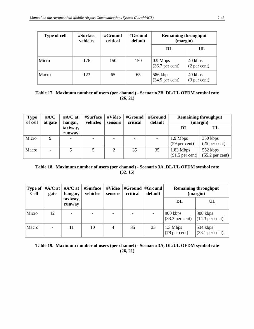
2.4.6.2 Tables 12, 13, 14, 15 and 16 below identify the resulting maximum number of users for
the different scenarios and different DL/UL ratios considered.
Type of cell #Video sensors Remaining throughput (margin)
DL UL
Micro 18 3.28 Mbps (99.5 per cent) 548 kbps (32.2 per cent)
Macro 7 1.99 Mbps (99.6 per cent) 552 kbps (55.2 per cent)
Table 12. Maximum number of users (per channel) - Scenario 1, DL/UL OFDM symbol rate
(32, 15)
Type of cell #Video sensors Remaining throughput (margin)
DL UL
Micro 24 2.67 Mbps (99.1 per cent) 564 kbps (26.8 per cent)
Macro 13 1.69 Mbps (99.2 per cent) 568 kbps (40 per cent)
Table 13. Maximum number of users (per channel) - Scenario 1, DL/UL OFDM symbol rate
(26, 21)
2-44 Manual on the Aeronautical Mobile Airport Communications System (AeroMACS)
Type of Cell #Surface
vehicles
#Video
sensors
#Ground
critical
#Ground
default
Remaining throughput
(margin)
DL UL
Micro 35 9 115 115 2.75 Mbps
(83.3 per cent)
544 kbps
(32 per cent)
Macro 13 3 45 45 1.8 Mbps
(90 per cent)
588 kbps
(58.8 per cent)
Table 14. Maximum number of users (per channel) - Scenario 2A, DL/UL OFDM symbol rate
(32, 15)
Type of
cell
#Surface
vehicles
#Video
sensors
#Ground
critical
#Ground
default
Remaining throughput
(margin)
DL UL
Micro 50 12 150 150 1.98 Mbps
(73.6 per cent)
532 kbps
(24.6 per cent)
Macro 20 8 65 65 1.4 Mbps
(82.4 per cent)
558 kbps
(39.8 per cent)
Table 15. Maximum number of users (per channel) - Scenario 2A, DL/UL OFDM symbol rate
(26, 21)
Type of
cell
#Surface
vehicles
#Ground
critical
#Ground
default
Remaining throughput (margin)
DL UL
Micro 143 115 115 1.93 Mbps
(58.4 per cent)
40 kbps
(2.4 per cent)
Macro 87 45 45 1.21 Mbps
(60.5 per cent)
40 kbps
(4 per cent)
Table 16. Maximum number of users (per channel) - Scenario 2B, DL/UL OFDM symbol rate
(32, 15)
Manual on the Aeronautical Mobile Airport Communications System (AeroMACS) 2-45
Type of cell #Surface
vehicles
#Ground
critical
#Ground
default
Remaining throughput
(margin)
DL UL
Micro 176 150 150 0.9 Mbps
(36.7 per cent)
40 kbps
(2 per cent)
Macro 123 65 65 586 kbps
(34.5 per cent)
40 kbps
(3 per cent)
Table 17. Maximum number of users (per channel) - Scenario 2B, DL/UL OFDM symbol rate
(26, 21)
Type
of cell
#A/C
at gate
#A/C at
hangar,
taxiway,
runway
#Surface
vehicles
#Video
sensors
#Ground
critical
#Ground
default
Remaining throughput
(margin)
DL UL
Micro 9 - - - - - 1.9 Mbps
(59 per cent)
350 kbps
(25 per cent)
Macro - 5 5 2 35 35 1.83 Mbps
(91.5 per cent)
552 kbps
(55.2 per cent)
Table 18. Maximum number of users (per channel) - Scenario 3A, DL/UL OFDM symbol rate
(32, 15)
Type of
Cell
#A/C at
gate
#A/C at
hangar,
taxiway,
runway
#Surface
vehicles
#Video
sensors
#Ground
critical
#Ground
default
Remaining throughput
(margin)
DL UL
Micro 12 - - - - - 900 kbps
(33.3 per cent)
300 kbps
(14.3 per cent)
Macro - 11 10 4 35 35 1.3 Mbps
(78 per cent)
534 kbps
(38.1 per cent)
Table 19. Maximum number of users (per channel) - Scenario 3A, DL/UL OFDM symbol rate
(26, 21)
2-46 Manual on the Aeronautical Mobile Airport Communications System (AeroMACS)
Type of
cell
#A/C at
gate
#A/C at
hangar,
taxiway,
runway
#Surface
vehicles
#Ground
critical
#Ground
default
Remaining throughput (margin)
DL UL
Micro 9 - - - - 1.9 Mbps
(59 per cent)
350 kbps
(25 per cent)
Macro - 8 10 35 35 1.69 Mbps
(84.5 per cent)
510 kbps
(51 per cent)
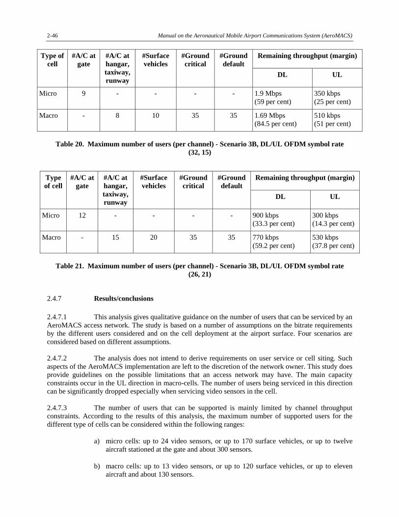
Table 20. Maximum number of users (per channel) - Scenario 3B, DL/UL OFDM symbol rate
(32, 15)
Type
of cell
#A/C at
gate
#A/C at
hangar,
taxiway,
runway
#Surface
vehicles
#Ground
critical
#Ground
default
Remaining throughput (margin)
DL UL
Micro 12 - - - - 900 kbps
(33.3 per cent)
300 kbps
(14.3 per cent)
Macro - 15 20 35 35 770 kbps
(59.2 per cent)
530 kbps
(37.8 per cent)
Table 21. Maximum number of users (per channel) - Scenario 3B, DL/UL OFDM symbol rate
(26, 21)
2.4.7 Results/conclusions
2.4.7.1 This analysis gives qualitative guidance on the number of users that can be serviced by an
AeroMACS access network. The study is based on a number of assumptions on the bitrate requirements
by the different users considered and on the cell deployment at the airport surface. Four scenarios are
considered based on different assumptions.
2.4.7.2 The analysis does not intend to derive requirements on user service or cell siting. Such
aspects of the AeroMACS implementation are left to the discretion of the network owner. This study does
provide guidelines on the possible limitations that an access network may have. The main capacity
constraints occur in the UL direction in macro-cells. The number of users being serviced in this direction
can be significantly dropped especially when servicing video sensors in the cell.
2.4.7.3 The number of users that can be supported is mainly limited by channel throughput
constraints. According to the results of this analysis, the maximum number of supported users for the
different type of cells can be considered within the following ranges:
a) micro cells: up to 24 video sensors, or up to 170 surface vehicles, or up to twelve
aircraft stationed at the gate and about 300 sensors.
b) macro cells: up to 13 video sensors, or up to 120 surface vehicles, or up to eleven
aircraft and about 130 sensors.
Manual on the Aeronautical Mobile Airport Communications System (AeroMACS) 2-47
2.4.7.4 Note that throughput margins should be left available in a BS, as was done in the
scenarios considered in this paper, in order to cope with peak traffic. Video peak traffic can be
particularly high and requires a large margin of available throughput (512 kbps assumed).
2.4.7.5 The analysis shows that micro cells are best suited to cover an area with many users
within a small range (such as the gate area), while macro cells cover larger areas with less users (such as
airport movement or maintenance areas).
2.4.7.6 If users transmitting a heavy bitrate are present, such as video sensors or aircraft stationed
at the gates, micro cells can be used to increase capacity to two to three times compared to the capacity
provided using macro cells. However, this is subject to restrictions on:
a) number of BSs intended to be deployed (including frequency reuse limitations);
b) availability of BS sites in the required areas (note that the micro cell has a limited
range); and
c) availability of network connections in the required sites.
2.4.7.7 Another technique to increase the cell throughput is to reduce the BS range (applying cell
siting) in order to increase the likely modulation code and thus increase the overall capacity of the cell.
This can be done via cell coverage overlap and load balance. In such a case, attention must be paid to the
limitation in the number of available channels which may lead to frequency reuse and increased
interference between cells.
2.4.7.8 When a large number of users transmitting a low bitrate is present (such as sensors), the
limitation is not the cell throughput but the maximum number of users allowed to be registered in the BS
equipment.
2.4.7.9 Another relevant conclusion of this analysis is the impact of the asymmetry of the
AeroMACS link. Note that, using the most symmetric DL/UL ratio (26, 21) in the AeroMACS profile the
number of users supported increases significantly. This is due to the fact that the UL direction has at least
as much traffic load as the DL direction in the scenarios of this analysis. This situation may occur in
operational deployments, especially if video sensors or aircraft are present. It is thus recommended to:
a) use appropriate DL/UL ratios in AeroMACS deployments that are expected to use
extensively UL capacity; and
b) consider the need to identify additional DL/UL ratio links (possibly in a future
revision of AeroMACS standards) that would support a higher share of the UL
capacity.
2.5 SPECTRAL MASK AND EMISSIONS
2.5.1 Section 7.4.5 of the SARPs provides the Standards for the spectral mask and emissions.
2.5.2 The appendix to this manual provides a test procedure to ensure that these requirements
are met. The test procedure is included in this manual as it shows key steps, such as:
a) how to avoid deterioration of testing accuracy caused by characteristics of the IF
filter provided in the spectrum analyser; and
2-48 Manual on the Aeronautical Mobile Airport Communications System (AeroMACS)
b) how to set up the 0dB reference for the spectrum mask measurement.
2.6 MANAGEMENT OF INTERFERENCE
2.6.1 Interference avoidance measures for AeroMACS
2.6.1.1 The ITU allocated the band, 5 030 to 5 150 MHz to AM(R)S. Currently, the 5 091 to
5 150 MHz band is the primary band targeted for AeroMACS implementation worldwide. In addition,
AeroMACS networks can also operate in the 5 000 to 5 030 MHz band on a regional basis. The number
of channels available for each airport system implementation will depend on the international and
regional channel allocation rules. The number of channels available for each system may be limited due
to potential interference with the Globalstar satellite system and/or policies and procedures specific to a
host State. For example, the CAA may or may not allow combining ATC and AOC traffic on the same
network or the same set of channels. Should the requirement to separate ATC and AOC traffic onto
different channels be imposed, the number of channels available for each network would be further
limited.
2.6.1.2 The number of BSs required for each AeroMACS implementation will depend on the size
of the geographic area to be covered and the volume of traffic the system needs to support. A system or
part of a system may be implemented with sectorized coverage where the region around a BS is divided
into sectors of coverage through the use of directional antennas and an AeroMACS transceiver for each
antenna.
2.6.1.3 Implementation of frequency reuse will be required if the number of BSs exceeds the
number of available channels or if there is a need to support higher volumes of traffic, thus placing more
than one channel on each BS. A frequency reuse scheme, i.e. how often each frequency is reused, will
depend on a specific system implementation and will require managing intra-system interference.
2.6.1.4 Interference must be managed if the system is to comply with the requirements outlined
in the AeroMACS SARPs. This will likely translate into avoiding adjacent channel assignments on
different sectors of the same site in a sectorized scenario. Co-channel assignments will need to be
separated as far as feasible avoiding overlapping coverage.
2.6.1.5 Various interference mitigation techniques are available to a system designer and
operator including, but not limited to, antenna downtilt, transmit power reduction, antenna height
variations, and careful site placement taking advantage of signal attenuation and blocking. Smaller sites,
i.e. smaller coverage areas, would make signal propagation easier to control but would result in a greater
number of BSs per airport thus necessitating increased frequency reuse. Additionally, mobility
management techniques are available to minimize potential interference effects.
2.6.2 AeroMACS planning against interference
2.6.2.1 AeroMACS planning method
2.6.2.1.1 AeroMACS service areas should be planned on the basis that the desired signal power
level (in dBm) at the receiver input inside a service area should exceed the AeroMACS receiver
sensitivity by the quantity 10log(1+(I/N)):
Manual on the Aeronautical Mobile Airport Communications System (AeroMACS) 2-49
Desired signal level ≥ Sensitivity + 10 log (1+ (I/N)).
where:
a) I is the cumulative mean interference power, adjusted to the selectivity of the RF and
IF sections of the AeroMACS receiver;
b) N is the total mean noise power in the IF bandwidth; and
c) in the above expression, both I and N are expressed in non-logarithmic units (mW)
and are referred to the receiver input.
2.6.2.1.2 It should be noted that the total mean noise power (N) in dBm equals the level of thermal
noise (Nth) plus the receiver’s noise figure (NF). The thermal noise in dBm is:
Nth = 10log(KTB) + 30,
where K is Boltzmann’s constant (1.38 × 10⁻²³ J/K), T is the absolute temperature of the receiver (in
Kelvin) in and B is the bandwidth of the receiver (in Hz).
For a 5 MHz bandwidth, Nth = -107.0 dBm and for NF = 8 dB, the level of the total mean noise power
equals N=-99.0 dBm.
2.6.2.1.3 The ratio I/N equals the relative increase (ΔT/T) of the receiver noise temperature due to
interference. Because the quantities I and N contain the effect of filtering, the ratio I/N can be thought of
as applying to the IF output as well.
2.6.2.2 Application of the planning method
2.6.2.2.1 The first choice the network designer has to make is over the maximum value of the ratio
I/N.
2.6.2.2.2 The greater the value of this ratio, the more tolerant will be the AeroMACS network to
interference. Caution needs to be exercised on increasing the value of this ratio as the greater the value of
this ratio, the higher the required level of the desired signal at the AeroMACS receiver. Consequently for
a given maximum BS EIRP, the higher the desired signal at the receiver, the smaller the effective range of
the base station.
2.6.2.2.3 It needs to be emphasized that “I” represents the cumulative interference. Hence the
network designer has to consider all possible interference sources that may affect simultaneously the most
vulnerable point of the network. In particular the cumulative interference “I” includes the co-channel and
adjacent-channel interference due to other AeroMACS emissions.
2.6.2.2.4 The existence of AeroMACS deployments in nearby airports (current or future planned)
should be investigated. It is recommended that local airports at a distance within the radio horizon are
considered and, if an interference level is deemed relevant, readjustments are made to the channels
available in each deployment.
2.6.2.2.5 The next step would be to allocate weights pj to the various concurrent interference
threats where:
Σj pj = 1.
2-50 Manual on the Aeronautical Mobile Airport Communications System (AeroMACS)
2.6.2.2.6 For each individual interference threat, the power threshold Ij (in dBm) at the input of an
AeroMACS receiver, when adjusted to the selectivity of the RF and IF sections of the AeroMACS
receiver, is then calculated as follows:
Ij = I + 10log (pj) = N + 10log (I/N) + 10log (pj),
where in the term 10log (I/N), I and N are expressed in non-logarithmic units.
2.6.2.2.7 The individual power threshold Ij can be subsequently utilized for the determination of
the threshold of the unadjusted interference power at the input of an AeroMACS receiver and thus for the
calculation of the required separation in terms of distance and/or frequency between the AeroMACS
receiver and the source of interference.
2.6.2.2.8 As an illustration, suppose that the choice I/N=1 is made for a given option of the
modulation (QAM) scheme and that there exists interference from (a) one AeroMACS adjacent channel,
(b) an off-channel telemetry application and (c) an MLS facility in the same airport.
Suppose that the choices for pj are :
pAeroMACS = 0.4, pATM = 0.3, pMLS = 0.3
The interference thresholds in dBm corresponding to each threat would then be:
IAeroMACS = I + 10log (pAeroMACS) = I – 4.0 = N – 4.0 = -103.0 dBm,
IATM = I + 10log (pATM) = I – 5.2 = N – 5.2 = -104.2 dBm,
IMLS = I + 10log (pMLS) = I – 5.2 = N – 5.2 = -104.2 dBm.
2.6.2.2.9 As for the determination of the unadjusted interference power threshold due to
AeroMACS adjacent-channel emissions, it is noted that for I/N = 1 one can benefit directly from the
implications of the AeroMACS adjacent-channel performance requirements because they are valid
subject to the same condition (I/N=1). In this case, if the only source of interference is an AeroMACS
transmitter on the adjacent channel, the power of the adjacent-channel transmission at the receiver input,
which is required to produce I=N, equals the power of the desired transmission (sensitivity + 3dB) plus
the so called adjacent-channel rejection R. In reference to the above example, there follows that the power
level Padj of the adjacent-channel transmission at the receiver input that is required to produce an adjusted-
by-filtering value of IAeroMACS = N – 4 = -103.0 dBm, is given by:
Padj = sensitivity + 3dB + R – 4 dB = sensitivity + R – 1 dB.
2.6.2.3 Sensitivity under mobility conditions and impact on interference planning
2.6.2.3.1 When a mobile station moves with velocity v, the errors in the decoding of received
signals come not only from the noise and the interference at the receiver but also from the doppler effect.
The amount of noise at the receiver does not change with the motion. However, the error is increased in
comparison with the static situation as a result of inter-symbol interference due to the doppler effect. If for
instance we chose to allocate the same rms doppler error as for the noise, it would be necessary to double
the power of the desired signal compared to its level in the static case, so that the ratio of the total rms
error to the amplitude of the desired signal remains as in the static situation. Hence in this case the
sensitivity of the receiver would be higher by 3 dB and this should also be considered in the planning
against interference. The need for a higher desired signal at an AeroMACS receiver to account for
doppler effects would further decrease the range of an AeroMACS BS (assuming the same maximum
EIRP level as in the static case). It is noted that a higher allocation of error to the doppler effect in order
Manual on the Aeronautical Mobile Airport Communications System (AeroMACS) 2-51
to cover the mobility requirements would necessitate a further increase in the level of the desired signal at
Airport Communications System (AeroMACS) – Aloke Roy et al.
Manual on the Aeronautical Mobile Airport Communications System (AeroMACS) 2-53
duration and their duty cycle is very low (less than 1 per cent), the fraction of the
time that AeroMACS reception will be interfered with will also be low.
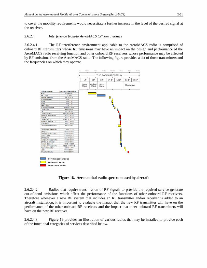
2.6.2.4.5 The AeroMACS radio will have to be certified for compliance with RF radiated and
conducted emissions out of the radio enclosure(s) and cabling connected to the unit, and for compliance
with RF susceptibility to radiated and conducted interference coupled via the cabling connected to the
AeroMACS radio per applicable industry standards.
2.6.2.5 Other systems occupying the spectrum
2.6.2.5.1 The AeroMACS unwanted emission (i.e. out-of-band and spurious emissions) levels are
specified in section 3.5 of the AeroMACS SARPs. Those levels are consistent with that required of
commercial IEEE802.16 devices.
2.6.2.5.2 AeroMACS operates in the AM(R)S, across at least the frequency 5 030 to 5 150 MHz
(see sections 2.1 and 3.2.1 of the AeroMACS SARPs). The expected initial operating band is 5 091 to
5 150 MHz.
2.6.2.5.3 During development of the AeroMACS SARPs it was noted that No. 5.443C of the ITU
Radio Regulations places additional requirements on AM(R)S operations in the 5 030 to 5 091 MHz band
to protect radio navigation satellite systems (RNSS) in the adjacent 5 010 to 5 030 MHz band. The
footnote was considered when developing the AeroMACS unwanted emission level requirements.
5.443C The use of the frequency band 5 030 - 5 091 MHz by the aeronautical mobile (R) service is
limited to internationally standardized aeronautical systems. Unwanted emissions from the
aeronautical mobile (R) service in the frequency band 5 030 - 5 091 MHz shall be limited to protect
RNSS system downlinks in the adjacent 5 010 - 5 030 MHz band. Until such time that an appropriate
value is established in a relevant ITU-R Recommendation, the e.i.r.p. density limit of -75 dBW/MHz
in the frequency band 5 010 - 5 030 MHz for any AM(R)S station unwanted emission should be used.
(WRC-12).
2.6.2.5.4 In particular, the following points were noted:
a) 5.443C does not apply to AeroMACS operation in 5 091 to 5 150 MHz where
near-term operations will occur. Though AeroMACS is capable of operating in 5 030
to 5 091 MHz, that band in ICAO is currently planned for control and non-payload
communications (CNPC) for remotely piloted aircraft systems (RPAS; termed
unmanned aircraft systems or UAS in ITU). RPAS CNPC will utilize a completely
different radio system;
b) the -75 dBW/MHz level in 5.443C is provisional and based on protection of RNSS
service links under certain conditions. Such RNSS service links do not currently
exist. Also the scenario utilized to derive the limit did not consider on-aircraft
interference from AeroMACS-to-RNSS. Such aircraft integration is beyond the
purview of ITU; and
c) RNSS feeder downlinks do exist in the 5 010 to 5 030 MHz frequency band,
however, they were not studied in the development of the -75 dBW/MHz provisional
limit. As a result, the level necessary to protect those systems is not known. It should
be noted that such feeder link receivers are usually associated with large dish
antennas and usually located in areas away from airports, while AeroMACS is
limited to operating on the surface of an aerodrome.
2-54 Manual on the Aeronautical Mobile Airport Communications System (AeroMACS)
2.6.2.5.5 Given the available information, the decision was taken to keep the unwanted emission
levels contained in section 3.5. If in the future AeroMACS is operated in 5 030 to 5 091 MHz, operating
RNSS systems will be protected as necessary. This may result in additional attenuation to AeroMACS
unwanted emissions below 5 030 MHz, and/or reduced AeroMACS operating power. This too could also
apply to other non-RNSS satellite systems as explained in the next section. 2.6.2.6 Interference to satellite systems
2.6.2.6.1 The potential of AeroMACS interference to the satellite fixed services transmissions
(FSS) has been debated in ITU at the WRC-07, as part of the agreement to allow AeroMACS to have an
AM(R)S allocation in the 5 GHz band.
2.6.2.6.2 The agreement at the WRC-07, constrains the AeroMACS usage on the airport surface,
requiring specific limitations (notably a maximum of a 2 per cent increase in the satellite receiver noise
temperature) to be met. Following this agreement, additional studies and investigations have been carried
out in Europe and the United States in particular to demonstrate that AeroMACS meets these
requirements.
2.6.2.6.3 The undertaken analysis considered future dense deployments of AeroMACS in all
regions of the world in order to simulate worst case scenarios (which will not be realized in the early
deployment of AeroMACS). In addition the analysis considered potential hot spots considering dense
simultaneous deployment both in Europe and the United States.
2.6.2.6.4 This section summarizes the analysis undertaken in one of the above studies and presents
as an example the assumptions and outcome of calculating aggregated emissions from all expected future
AeroMACS deployments so that AeroMACS implementations:
a) are compliant with the ITU co-interference requirements (WRC-07); and
b) do not adversely affect the Globalstar satellite feeder links.
2.6.2.6.5 This material is provided in the AeroMACS Manual as guidance and explanatory
material to capture some relevant implementation considerations. It is important to note that in WRC-15
some of the limitations agreed in WRC-07 were reconsidered (i.e. the 2 per cent limit was increased to
5 per cent which adds margin in the implementation considerations.
2.6.2.6.6 In the WRC-07 discussions the threshold interference power level for Globalstar at low
earth orbit (LEO) has been established at -157.3 dBW corresponding to a maximum 2 per cent increase of
the satellite receiver’s noise temperature.
2.6.2.6.7 In order to establish power limits for AeroMACS base station transmitters and to avoid
interference with the Globalstar uplinks, the AeroMACS base stations with sector antenna transmitters
were modelled at 6 207 airports in Europe, the United States and the rest of the world. The following
assumptions were applied related to large, medium and small size category airports of the simulation:
a) large size airports:
1) US categories: 35 operational evolution partnership airports (OEP 35);
2) Europe: 50 largest European airports according to Wikipedia list.
b) medium size airports:
Manual on the Aeronautical Mobile Airport Communications System (AeroMACS) 2-55
1) 123 US category Class C airports;
2) Europe: 50 medium category airports according to Wikipedia list rank 51 to 100;
c) small size airports:
1) all other airports in open flights database.
2.6.2.6.8 In the model used in the investigations, each large airport is assigned six 120° sector
antennas, each medium airport is assigned three 120° sector antennas and each small airport is assigned
one 120° sector antenna. Several simulation runs were applied with different random antenna directions.
This is equivalent to assume a horizontal omnidirectional station pattern as a mean.
2.6.2.6.9 The simulations assumed that large airports will use all eleven 5 MHz channels, medium
airports will use six 5 MHz channels and small airports will use one 5 MHz channel. Small airports are
only allowed transmitting half as much power per sector as the medium and large airports. This takes into
account that at smaller sites it is expected that AeroMACS is not permanently running.
2.6.2.6.10 Finally, the following assumptions for EIRP, MIMO system and antenna pattern have
been applied:
a) EIRP is the sector transmit power at the antenna input plus antenna gain;
b) maximum allowable EIRP in a base station sector must be the sum of both transmit
power amplifiers in a 2-channel MIMO system; and
c) base station sector patterns are defined to be ITU-R-F-1336-2 reference patterns with
120° 3 dB beam width toward the horizon.
2.6.2.6.11 Based on the simulations, the analysis concluded that under the assumptions considered
the AeroMACS deployment will be meeting the ITU WRC-07 requirements, when the worldwide
deployment of AeroMACS base stations observe the following emissions limitations:
a) the total base station EIRP in a sector was assumed not to exceed:
1) 39.4 dBm for elevation angles up to 1.5 degrees;
2) 39.4 dBm linearly decreasing (in dB) to 24.4 dBm for elevation angles from 1.5
to 7.5 degrees;
3) 24.4 dBm linearly decreasing (in dB) to 19.4 dBm for elevation angles from 7.5
to 27.5 degrees;
4) 19.4 dBm linearly decreasing (in dB) to 11.4 dBm for elevation angles from 27.5
to 90 degrees;
b) the total mobile station EIRP is not assumed to exceed 30 dBm.
Note.― The above ground antenna elevation pattern is contained in ITU-R F.1336-2.
2.6.2.6.12 The antenna pattern identified in the above analysis is one that has been shown via
simulations to meet the WRC-07 requirements. However, it is not specified or recommended to be
included in the requirements as other patterns may also be suitable.
2-56 Manual on the Aeronautical Mobile Airport Communications System (AeroMACS)
2.6.2.6.13 The information in this section aims to raise the awareness of the AeroMACS
implementers that in eventual dense (end-state) AeroMACS deployment, the antenna pattern of the
(ground) base stations and the antenna tilt, need to be carefully considered to avoid any impact to FSS
systems and to continue meeting any applicable ITU requirement.
2.6.2.6.14 However, this issue (minimization of impact to FSS) cannot be addressed locally at the
level of a single airport or in one region only, as it is the global aggregate interference impact that is
important.
2.6.2.6.15 In order to minimize impact to FSS, it is also important that, particularly in the case of
smaller airports, potentially using a limited number of channels, the choice of the channels is spread
among different airports to avoid some channels being over assigned (and over used) while others being
under assigned (and under used).
2.6.2.7 Interference to/from other AeroMACS systems
2.6.2.7.1 The existence of AeroMACS deployments in nearby airports (current or future planned)
should be investigated. It is recommended that local airports at a distance within the radio horizon are
considered and, if interference level is deemed relevant, readjustments are made to the channels available
in each deployment.
2.7 ANTENNAE/MIMO
2.7.1 Multiple-input multiple-output (MIMO) is a system with plural antennas to improve the
system coverage or throughput [1].
2.7.2 There are two types of MIMO modes. One is MIMO matrix A (MIMO-A), the other is
MIMO matrix B (MIMO-B). MIMO-A employs two transmitting (Tx) antennas and one or two receiving
(Rx) antenna to improve coverage by sending the same data via Tx antennas and combining them at the
receiver. MIMO-A can be implemented in onboard MS with only one receive antenna.
2.7.3 On the other hand, MIMO-B employs two Tx antennas and two Rx antennas to increase
throughput by dividing a single data stream and sending the resulting streams over two antennae in
parallel.
2.7.4 AeroMACS should support downlink MIMO-A.
Note.― When applications demand the greater throughput provided by MIMO-B, this may be
considered for aircraft.
2.7.5 MS installed on ground vehicles or other use cases except for aircraft is recommended to
support both MIMO-A and MIMO-B to obtain better throughput.
2.7.6 BSs are recommended to support both MIMO-A and MIMO-B. BS will accept many
MSs with various types of MIMO mode simultaneously. MIMO-B is available only when both BS and
MS support it.
Manual on the Aeronautical Mobile Airport Communications System (AeroMACS) 2-57
2.8 SENSITIVITY
2.8.1 The sensitivity level is defined as the power level measured at the receiver input when the
BER is equal to 1*10-6.
2.8.2 The computation of the sensitivity level for the AeroMACS system is based on the
following formula:
Where:
* -114: is the thermal noise power term in dBm, referred to 1 MHz
bandwidth and 300 K temperature.
* SNRRX: is the receiver SNR , it can be defined as the SNR necessary , at the
demodulator input, to get the desired BER for the given modulation
and coding rate.
* R: is the repetition factor.
* Fs: is the sampling frequency in Hz.
* NFFT: is the FFT size.
* Nused: is the number of subcarrier used (FFT size – number of guard-band
subcarriers – DC carrier).
* ImpLoss: is the implementation loss, which includes non-ideal receiver effects
such as channel estimation errors, tracking errors, quantization
errors, and phase noise. The assumed value is 5 dB.
* NF: is the receiver noise figure, referenced to the antenna port. The
assumed value is 8 dB.
2.8.3 The SNRrx depends on the modulation and coding scheme selected ( a QPSK 1/2 needs a
lower SNR than a 64 QAM 3/4 to get the same BER); in case of convolutional coding the values defined
are:
2-58 Manual on the Aeronautical Mobile Airport Communications System (AeroMACS)
Receiver SNR
Modulation Coding Receiver SNR (dB)
QPSK 1/2 5
QPSK 3/4 8
16-QAM 1/2 10.5
16-QAM 3/4 14
64-QAM 1/2 16
64-QAM 2/3 18
64-QAM 3/4 20
Table 22. Receiver SNR
2.8.4 Using the above parameters in the formula (1) and applying them to Table 22, we get the
sensitivity values listed in Table 22.
Modulation Scheme Rep. Factor Sensitivity
64-QAM 3/4 1 -76.37 dBm
64-QAM 2/3 1 -78.37 dBm
16-QAM 3/4 1 -82.37 dBm
16-QAM 1/2 1 -85.87 dBm
QPSK 3/4 1 -88.37 dBm
QPSK 1/2 1 -91.37 dBm
QPSK 1/2 2 -94.37 dBm
Table 23. AeroMACS receiver sensitivities: RSS
2.9 SYSTEM ARCHITECTURE
2.9.1 General
2.9.1.1 Figure 20 provides a logical representation of the overall networks at an airport.
Manual on the Aeronautical Mobile Airport Communications System (AeroMACS) 2-59
Figure 20. Network at a typical airport
2.9.1.2 The aviation internet (IPS) may comprise various networks with different administrative
domains as explained below:
a) ANSP stands for air navigation service provider, the entity that manages the flight
traffic in a region or in a State. ANSPs have their networks deployed to support the
air traffic applications. ANSP networks belonging to various regions are
interconnected to each other and thus provide a global network for data link services.
b) Airport network supports various airport services. Airport network may provide
infrastructure for airport service providers to register and host its airport services in
global or site-local domains. Site-local services will be available within the airport
network only while global services will be available to anyone in the global aviation
internet. An example of a site-local application could be the real-time broadcast of
surface vehicle position information. Such real-time information need not be
broadcasted in the global domain.
c) AeroMACS network, in the context of aircraft, provides mobile connectivity to
aircraft to access airport network. It has the infrastructure to support dynamic
connections, to handle subscriptions for mobile users and to ensure authenticity and
privacy needed for aircraft’s safety communications. It corresponds to AeroMACS
ASN and CSN in the reference model. AeroMACS network may also offer other
fixed link services for interconnecting various networks within the airport domain.
d) ASP/airline networks should be considered as private enterprise networks. An airport
is expected to have multiple ASP networks. ASPs can host its servers/applications
that are required to be accessed by external entities in the perimeter network (in a
de-militarized zone (DMZ)), while the internal network elements should be kept
inside the closed aviation network. For example, consider a weather service provider
network at an airport. The network may comprise sensors installed at various places
AeroMACS Network
2-60 Manual on the Aeronautical Mobile Airport Communications System (AeroMACS)
of an airport, servers to collect and process information from various sensors, routers,
networking devices, personal computers for staff, internal mail servers etc., placed in
the closed network, while the dispatch server that provides consolidated weather
information to aircraft kept in the de-militarized zone (DMZ). 2.9.2 Network overview and architecture
This section provides an overview of the AeroMACS network based on the network reference model
describing the functional blocks and reference points of the access service network (ASN) and
connectivity service network (CSN). Secondly, an end-to-end AeroMACS service network architecture is
proposed based in the network reference model.
2.9.2.1 Network reference model (NRM)
2.9.2.1.1 General
2.9.2.1.1.1 The network reference model (NRM) does not necessarily define physical entities but
instead groups the functions to be performed into functional blocks with a simple logical interface
between them.
2.9.2.1.1.2 The NRM is a general logical representation of the network architecture, including
AeroMACS, based on the IEEE standard (7). The NRM identifies functional entities and the reference
points (RPs) over which interoperability is achieved between them. Each of the entities, SS, BS, ASN and
CSN represents a grouping of functional entities. A reference point represents a conceptual link that
connects different functions of different functional entities. RPs are not necessarily a physical interface.
These functions make use of various protocols associated with an RP. Figure 21 introduces overall
interoperability reference points between AeroMACS functional entities.
2.9.2.1.1.3 The intent of the NRM is to allow multiple implementation options for a given functional
entity while achieving interoperability among different realizations of functional entities. Interoperability
is based on the definition of communication protocols and data plane treatment between functional
entities, to achieve an overall end-to-end function, for example, security or mobility management. Thus,
the functional entities on either side of a reference point represent a collection of control and bearer plane
end-points. In this setting, interoperability may be verified based only on protocols exposed across an RP
which would depend on the end-to-end function or capability realized (based on the usage scenarios
supported by the overall network).
2.9.2.1.1.4 The NRM specifies the normative use of protocols over an RP for such a supported
capability. If an implementation claims support for the capability and exposes the RP then the
implementation needs to comply with this specification. This avoids the situation where a protocol entity
may reside on either side of an RP or the replication of identical procedures across multiple RPs for a
given capability.
Manual on the Aeronautical Mobile Airport Communications System (AeroMACS) 2-61
Figure 21. Overall network reference model
2.9.2.1.1.5 All protocols associated with an RP may not always terminate in the same functional
entity, i.e. two protocols associated with an RP need to be able to originate and terminate in different
functional entities.
2.9.2.1.1.6 The normative reference points between the major functional entities are the following:
Reference Point R1
Reference Point R1 consists of the protocols and procedures between an SS and a BS as part of
the ASN air interface (PHY and MAC) specifications (see also ASN reference model outlined
later in this section). Reference Point R1 may include additional protocols related to the
management plane.
Reference Point R2
Reference Point R2 consists of protocols and procedures between the SS and CSN associated
with authentication, services authorization and IP host configuration management. This reference
point is logical in that it does not reflect a direct protocol interface between SS and CSN.
The authentication part of Reference Point R2 runs between the SS and the CSN operated by the
home NSP, however the ASN and CSN operated by the visited NSP may partially process the
aforementioned procedures and mechanisms.
Reference Point R2 may support IP host configuration management running between the SS and
the CSN (operated by either the home NSP or the visited NSP).
ANSP, ACSP
2-62 Manual on the Aeronautical Mobile Airport Communications System (AeroMACS)
Reference Point R3
Reference Point R3 consists of the set of control plane protocols between the ASN and the CSN
to support AAA, policy enforcement and mobility management capabilities. It also encompasses
the bearer plane methods (e.g. tunnelling) to transfer user data between the ASN and the CSN.
One of the protocols foreseen on this RP is RADIUS.
In section 2.9.1.3.8.6 concerning deployment scenarios, some particular internetworking
relationships will be described between ASN and CSN for:
a) sharing an ASN by multiple CSN; and
b) providing service to roaming SS.
Reference Point R4
Reference Point R4 consists of the set of control and bearer plane protocols
originating/terminating in various functional entities of an ASN that coordinate SS mobility
between ASNs and ASN-GWs. R4 is the only interoperable RP between similar or heterogeneous
ASNs.
Reference Point R5
Reference Point R5 consists of the set of control plane and bearer plane protocols for
internetworking between the CSN operated by the home NSP and that operated by a visited NSP.
This reference point will only exist between CSNs that have an institutional or business
relationship which requires such internetworking.
Reference Point R6
Reference Point R6 consists of the set of control and bearer plane protocols for communication
between the BS and the ASN-GW. The bearer plane consists of intra-ASN data path between the
BS and ASN-GW. The control plane includes protocols for data path establishment, modification,
and release control in accordance with the MS mobility events. R6 also serves as conduit for
exchange of MAC state information between neighbouring BSs except when protocols and
primitives over R8 are used. The main protocol often used in this interface is an IP-in-IP
tunnelling protocol, named GRE (generic encapsulation protocol).
Reference Point R8
Reference Point R8 specifies the information exchange between BS belonging to the same ASN
for resource management or load balancing purposes.
Note.― Reference Point 7 has been deleted by the IEEE, however, remaining numbering has
been maintained.
Manual on the Aeronautical Mobile Airport Communications System (AeroMACS) 2-63
2.9.2.1.2 ASN reference network
2.9.2.1.2.1 General
2.9.2.1.2.1.1 The ASN defines a logical boundary and represents a convenient way to describe an
aggregation of functional entities and corresponding message flows associated with the access services.
The ASN represents a boundary for functional interoperability with AeroMACS clients, AeroMACS
connectivity service functions and aggregation of functions embodied by different vendors. Mapping of
functional entities to logical entities within ASNs as depicted in the NRM is informational.
2.9.2.1.2.1.2 The ASN reference model is illustrated in Figure 22. An ASN shares R1 reference point
(RP) with an SS, R3 RP with a CSN and R4 RP with another ASN. The ASN consists of at least one
instance of a base station (BS) and one instance of an ASN Gateway (ASN-GW). The R4 reference point
is the only RP for control and bearer planes for interoperability between similar or heterogeneous ASNs.
Interoperability between any type of ASN is feasible with the specified protocols and primitives exposed
across R1, R3 and R4 reference points.
2.9.2.1.2.1.3 It is highly desirable that inter-ASN mobility is supported in an airport to minimize
latency outages on the airport surface.
2.9.2.1.2.1.4 For the inter-ASN mobility applicable protocols and procedures should comply with the
Reference Point R4.
Figure 22. Detailed AeroMACS ASN reference model
2-64 Manual on the Aeronautical Mobile Airport Communications System (AeroMACS)
2.9.2.1.2.2 SS and BS definition
2.9.2.1.2.2.1 The SS and BS are specific AeroMACS entities that manage the user and control planes
of the physical and medium access layers of the subscriber node and the access network, respectively.
Their functions are fully described by IEEE 802.16-2009 Standard.
2.9.2.1.2.2.2 The AeroMACS base station (BS) is a logical entity that embodies a full instance of the
MAC and PHY in compliance with the AeroMACS specifications.
2.9.2.1.2.2.3 A BS instance represents one sector with one frequency assignment. It incorporates
scheduler functions for uplink and downlink resources, which will be left for vendor implementation and
are outside the scope of this document.
2.9.2.1.2.3 ASN gateway definition
2.9.2.1.2.3.1 As explained in 2.2.1.1.1, the ASN is not necessarily a physical entity but a functional
block performing the following functions.
2.9.2.1.2.3.2 The ASN gateway (ASN-GW) is a logical entity that represents an aggregation of control
plane functional entities that are either paired with a corresponding function in the ASN (e.g. BS instance),
a resident function in the CSN or a function in another ASN. The implementation of the ASN-GW is
outside the scope of this document.
2.9.2.1.2.3.3 The ASN-GW is the main actor on the network topology on which rely most of the
management and control procedures to support the data link and its interconnection with the backbone.
Figure 23 summarizes the functions attributable to the ASN-GW.
2.9.2.1.2.3.4 One ASN-GW is expected to be deployed per access service network. As depicted, the
main interfaces for the ASN-GW are: the R6 reference point which connects it to the BSs and the R3
reference point which deals with the interconnection to the CSN. In the cases such as a small airport with
a single ASN and where the ASN-GW and BSs are integrated into one physical entity, nonetheless the R6
interface is to be exposed.
Manual on the Aeronautical Mobile Airport Communications System (AeroMACS) 2-65
Figure 23. Main functionalities of AeroMACS ASN-GW
Note.― IP addressing model and access router functions are implementation options and may
reside outside the ASN-GW.
2.9.2.1.2.3.5 According to the AeroMACS network architecture reference model, a generic ASN-GW
covers the features/functionalities shown:
a) AeroMACS Layer 2 (L2) connectivity with SS;
b) relay functionality for establishing IP connectivity between the SS and the CSN;
c) network discovery and selection of the AeroMACS subscriber’s preferred NSP;
d) subscriber IP address allocation by querying the DHCP server for network
establishment and DHCP DISCOVER messages forwarding;
e) IP forwarding to/from the backhaul via MIP foreign agent (FA);
f) connection admission control to ensure service quality and different grades of service
commitment and provision;
g) AAA proxy/client. AeroMACS ASN-GW will trigger the exchange of susceptible
subscriber information and transfer AAA messages of AeroMACS subscriber’s
visited NSP for authentication, authorization and accounting to the home NSP;
h) context management. Transfer of subscriber credentials (it can store user’s profiles or
just cache them). Consequently, key distribution between entities;
2-66 Manual on the Aeronautical Mobile Airport Communications System (AeroMACS)
i) user profile management. After the authorization phase and key exchange, the user
profile is handled in order to create corresponding SFs;
j) data path establishment and service flow authorization (SFA). ASN-GW creates one
data path per SF. According to a predefined profile, ASN-GW will receive the
mapping of CID to SFID from the BS. If GRE tunnelling is used, then there will be
one GRE tunnel per SF; and
k) mobility management and handover control.
2.9.2.1.2.4 AeroMACS ASN profile
2.9.2.1.2.4.1 While the grouping and distribution of functions into physical devices within the ASN is
an implementation choice, the AeroMACS architecture specification defines one ASN interoperability
profile.
2.9.2.1.2.4.2 A profile maps the ASN functions into the BS and ASN-GW so that protocols and
messages, over the exposed reference point, are identified. The following text describes WiMAX forum
ASN Profile C based on [3].
Note.― The depiction of a function on either the ASN-GW or the BS in Figure 22 below, does not
imply that the function exists in all manifestations of this profile. Instead, it indicates that if the function
existed in a manifestation it would reside on the entity shown. Identification of the ASN Profiles was done
for the specific goal of providing a framework for interoperability among entities inside an ASN.
2.9.2.1.2.4.3 According to Profile C, ASN functions are mapped into ASN-GW and BS as shown in Figure 24. The key attributes of Profile C are:
a) handover (HO) control is in the base station;
b) radio resource control (RRC) is in the BS that would allow radio resource
management (RRM) within the BS. An “RRC relay” is in the ASN GW, to relay the
RRM messages sent from BS to BS; and
c) ASN anchored mobility among BSs is achieved by utilizing R6 and R4 logical
connections.
Manual on the Aeronautical Mobile Airport Communications System (AeroMACS) 2-67
Figure 24. WMF ASN Profile C
For more details refer to [2].
2.9.2.1.2.5 CSN reference network
The CSN, as shown in Figure 25, is the network that provides end-to-end connectivity to AeroMACS
subscribers with network entities and enables the provision of services by AeroMACS application service
providers (ASP). CSN main functionalities are AAA server and DHCP server. The applicable RP are R3
(CSN with ASN) and R5 (between two CSN). CSN internal reference points are out of scope of this
specification.
2-68 Manual on the Aeronautical Mobile Airport Communications System (AeroMACS)
Figure 25. Detailed AeroMACS CSN reference model
2.9.2.1.2.6 AAA proxy/server
2.9.2.1.2.6.1 During logon aircraft credentials are presented to the AeroMACS CSN AAA server.
AAA server verifies the credentials and checks the policy database in the context of aircraft before
authorizing it. The AAA then informs the ASN about the successful completion of authentication, the SS
authorization profile (i.e. assigned service flows and associated QoS parameters) and the required security
context (i.e. MSK and its lifetime) to be used.
2.9.2.1.2.6.2 Local users in an airport (e.g. handling vehicles) will be managed by an airport AAA
server via the ASN-GW. For non-local users (such as an aircraft) the likely scenario will involve a AAA
proxy in the airport that will send queries and requests to the H-NSP, which will manage airborne user
authentication and policy function (PF). AAA proxy covers the following functionalities:
a) support network entry when required, in case MS connects to V-NSP;
b) simplify connection to several CSN; and
c) security capability that allows authentication of MS locally.
2.9.2.1.2.6.3 AAA servers deployed at each airport can be connected via a proxy network. This allows authentication of subscribers beyond the region of the service in the airport. However, the mechanisms to establish this proxy network are out of the scope of this document.
2.9.2.1.2.6.4 By default, the IETF RADIUS protocol is supported as the main protocol for AAA
purposes.
2.9.2.1.2.6.5 Key exchange using PKMv2 will rely on the fact that in AeroMACS user (subscriber)
authentication is required. EAP-TLS framework is the defined suite to give support to user authentication.
The aircraft router will use X.509 certificates for EAP-TLS authentication. A C/N (common name) realm,
such as an airline name (as network domains are currently defined by ICAO), or any PKI provider name
DHCP Server
Manual on the Aeronautical Mobile Airport Communications System (AeroMACS) 2-69
can be used for EAP-TLS. The H-NSP AAA server will receive authentication traffic with the username
realm, which implies that the airport proxy AAA will need to map the realm value to the H-NSP AAA
address.
2.9.2.1.2.6.6 ASN-GW makes use of RADIUS protocol to support service authorization. AAA server
is also involved in checking the QoS policy for a given SS and consequently creation of a service flow
authorization (SFA) by ASN-GW in response to a service flow initiation request from the SS.
2.9.2.1.2.6.7 AAA servers will depend on the core network managed by the network service provider.
AAA server databases could belong to the visited network of each airport; they could belong to the same
virtual segment of network as AeroMACS or be held remotely in a different facility of the operator and
therefore in another network (namely, the home network).
2.9.2.1.2.6.8 IPsec support for the transport of all connections is envisaged. Moreover, the use of VPN
tunnelling is encouraged to secure all the connections to the remote elements of the backbone of the
network. This is a local implementation issue and out of scope of this document.
2.9.2.1.2.7 DHCP server
The DHCP server resides in the local CSN, which could be operated by the visited or home NSP. IP
address assignment will be done after the SS has performed full network entry if dynamic addressing is
used. Alternatively, static addressing can be utilized.
2.9.2.2 AeroMACS network architecture
2.9.2.2.1 General
2.9.2.2.1.1 The network reference model is valid to support the integration of AeroMACS data link
within the IPS backbone and give the corresponding service support. The overall principles followed to
Functional decomposition: The proposed architecture allows that required features are
decomposed into functional entities. The reference points are means to provide multivendor
interoperability. For interoperability purposes, special care must be paid to the Reference Points
R1 and R6 of the ASN reference model. Intra ASN mobility will imply full support of R6 control
messages.
Modularity and flexibility: The modularity of the proposed architecture gives the means to
adapt to different AeroMACS deployments, and the interconnection to the ground infrastructure.
As an example, the interconnection of different CSN topologies with just one single access
network is permitted. The architecture also enables the scalability of the network in case after
initial deployment the number of BSs installed within the airport needs to be increased in order to
support more users.
Decoupling the access and connectivity services: This architecture enables full mobility with
end-to-end QoS and security support, making the IP connectivity network independent from the
AeroMACS radio specification. In consequence, this allows for unbundling of access
infrastructure from IP connectivity services.
Support to a variety of business models: AeroMACS architecture supports the sharing of
different aviation business models. The architecture allows a logical separation between the
network access provider (NAP), the entity that owns and/or operates the access network, the
network service provider (NSP) and the application service providers (ASP).
2-70 Manual on the Aeronautical Mobile Airport Communications System (AeroMACS)
2.9.2.2.1.2 The reference points can represent a set of protocols to give control and provide
management support on the bearer plane. On any deployment, functional entities here depicted could be
matched to more than one physical device. In a similar manner, most of the reference points are left open.
The architecture does not preclude different vendor implementations based on different decompositions or
combinations of functional entities.
2.9.2.2.1.3 Figure 26 presents an example of a high-level functional architecture to support
communication with ground vehicles (airport operation) and aircraft (ATC, AOC). In such a case, at the
airport, in addition to AeroMACS specific systems (base stations and ASN gateway), AAA server and
DHCP server need to be deployed to enable communication with airport vehicles. The airport operator
network would thus act as the home network for airport vehicles.
2.9.2.2.1.4 For ATC and AOC service provision, the airport network would act as visited network,
the home network being implemented at regional or global scale for aircraft. The airport AAA server
would thus act as an AAA proxy for aircraft relaying authentication and authorization requests from the
ASN gateway to the home-NSP, which is the administrative authority that can operate one or more home
agents (HA). Regarding IP connectivity, it is possible that IP addresses will be assigned directly by an
H-NSP or a global DHCP. However, the most likely case is that an IP address will be assigned locally to
the MS and, in the case of an aircraft with a permanent IP address, it will be announced to the network.
The ASN gateway would also relay a DHCP request to the aircraft home network DHCP server. For
global connectivity and mobility support, the ASN will rely on a HA operated by an H-NSP.
Manual on the Aeronautical Mobile Airport Communications System (AeroMACS) 2-71
Figure 26. Typical AeroMACS network entities at an airport offering ASN and CSN functions
2.9.2.2.2 Mobility
2.9.2.2.2.1 Doc 9896 identifies mobile IPv6 as the mechanism to provide global mobility among
access networks in the ATN. This is currently under review as the IPS requires the use of bidirectional
tunnelling, i.e. routing packets from source to destination through the HA in both directions, which may
lead to suboptimal routes.
2.9.2.2.2.2 It is foreseen that global IPv6 addresses will be assigned to specific aircraft or on-board
data link equipment such as AeroMACS. This can be done via static IP addresses or dynamically via
mobile IP mechanisms. The support of dynamic IP addresses allocation (DHCP) and roaming for aircraft
needs the support of global IP mobility and contractual agreements between NSPs or network access
providers (NAPs) in order to allow the global identification and operation of airborne devices. Subscriber
and home agents (HA) will implement the mobility solution to be specified in Doc 9896. According to [9],
an IPS MSP operates one or more home agents.
2.9.2.2.2.3 The redirection of an incoming packet to the home network from the visited network
where the aircraft is currently in is done through a tunnel established between HA and forwarding agent
(FA) or access router (AR).
2.9.2.2.2.4 HA location could vary in a real scenario and can be centralized or decentralized,
whereas the AAA is expected to act as a proxy only in the V-NSP. This foreseeable scenario is depicted
in Figure 27.
2-72 Manual on the Aeronautical Mobile Airport Communications System (AeroMACS)
Figure 27. AeroMACS AAA and HA deployment scenario
2.9.2.2.2.5 Several options for the location of the FA/AR are envisaged, namely:
a) physically inside the ASN-GW equipment (as in Profile C) and dedicated to mobility
functions only for the MSs in the ASN;
b) as a separate entity in the local airport network and dedicated to mobility functions
only for the MSs in the ASN; and
c) as a separate entity in the local airport network and able to perform mobility
functions for any node in the local network, including one or more AeroMACS ASN
and other IP end nodes.
Note.― The FA/AR will not, in any case, operate to provide IP connectivity and mobility
functions to other data links other than AeroMACS.
2.9.2.2.3 IP address configuration
2.9.2.2.3.1 An AeroMACS service provider may choose to have a centralized CSN managing
multiple ASNs in different airports.
2.9.2.2.3.2 Alternatively, ASN gateway (acting as a DHCP proxy) contacts the airport network
gateway (which acts as DHCP server) to get IP address for aircraft’s AeroMACS connection. This IP
address is expected to be unique in the scope of global aviation internet. If the aviation internet (IPS)
supports dynamic DNS service for aircraft, aircraft registers its new IP address with the DNS services.
Manual on the Aeronautical Mobile Airport Communications System (AeroMACS) 2-73
2.9.2.2.3.3 Following the network entry procedure, an AeroMACS SS can reach the connection
establishment state and belong to a broadcast domain (Layer 2), thereby getting access to network
elements beyond the BS which at data plane level is just bridging air and wireline media. Therefore, once
Layer 2 is granted, the question on who is listening to the SS broadcast messages to obtain an IP comes
up. The forthcoming procedures depend on the type of IP version convergence sublayer established in the
previous phases.
2.9.2.2.3.4 For IPv6, from the AeroMACS SS perspective the first hop router is the access router in
the ASN-GW.
Figure 28. AeroMACS IPv6 data connectivity network elements
2.9.2.2.3.5 The SS performs initial network entry to activate the initial service flows. The
establishment of the IPv6 initial services flows enables the sending and receiving of IPv6 packets between
the SS and the access router. Then router advertisement and address assignment procedures are initiated.
2.9.2.2.3.6 The information contained in the router advertisement message is learnt by the ASN from
the attributes present in the RADIUS authentication accept message sent by the authentication server
during the network authentication phase. That content will depend on the network operator access policies.
2.9.2.2.3.7 Then the ASN advertises an IPv6 prefix from a preconfigured pool of prefixes belonging
to the attached CSN. In case of NAP sharing, the ASN may have several different prefix pools associated
with different CSN. In such case, the ASN uses the realm part of the network address identifier (NAI) to
select an appropriate pool to set in the IPv6 router advertisement messages to send to the incoming SS [5].
2.9.2.2.3.8 The message sequence chart in Figure 29 describes the sequence of protocol messages
exchanged between the SS and the network during the IP address allocation phase.
Core Router
IPv6 Access Router
MS
ASN CSN
External network (service
s)
SS
2-74 Manual on the Aeronautical Mobile Airport Communications System (AeroMACS)
Figure 29. AeroMACS IPv6 data connectivity establishment message sequence chart
2.9.2.2.3.9 After the Layer 3 path is established the following diagram model is in place for a typical
deployment scenario:
Figure 30. AeroMACS data plane typical deployment
2.9.2.2.3.10 All operations services at Layer 3 are reachable by the MS. This model supports the
extension to any service such as IMS, SNMP management, TFTP configuration server, subscriber/policy
management, etc. The external networks can be any of these: other network service providers (NSPs), a
corporate VPN (airline network), aeronautical internet or any other application partner.
Visited NSP Home NSP
AeroMACS NAP
MS BS Core
Router AAA Access Router
IPv6 Router Advertisement
L-3 Path Established (User traffic)
L-2 Link Established
L-3 Path Established
Accept: “IPv6 prefix information”
MS performs network address auto configuration
AeroMACS NAP
MS BS
Access router
BS
MS L-3 link
L-3 link
L-3 link
Operations
DHCP server
DNS server
L-3 link
External Networks
L-3 link
Other services
Core Router
NSP
SS
SS
Manual on the Aeronautical Mobile Airport Communications System (AeroMACS) 2-75
2.9.3 Network deployment scenarios
2.9.3.1 Business relationships in AeroMACS
2.9.3.1.1 The NAP is the entity that owns and operates the access network providing the radio
access infrastructure to one or more NSPs. Similarly; the NSP is the entity that owns and provides the
subscriber with IP connectivity and services by using the ASN infrastructure provided by one or more
NAPs. An NSP can be attributed as a home NSP or a visited NSP from the subscriber’s point of view. A
home NSP maintains service level agreements (SLA), authenticates, authorizes, and charges subscribers.
A home NSP can establish roaming agreements with other NSPs, which are called visited NSPs and are
responsible to provide some or all subscribed services to the roaming users. Within the aeronautical
environment, the following actors could make use of AeroMACS business entities:
a) ANSP (air navigation service provider) as the owner and operator of the national
navigation service network;
b) airport authorities may offer AeroMACS services to aircraft. The subscription may
offer a combination of network access and airport services provided by that airport
authority;
c) airlines may have their dedicated AeroMACS service for their aircraft exclusively.
Large airlines may even have their own AeroMACS infrastructure deployed at
airports to service their aircraft;
d) ACSP (aeronautical communication service provider) e.g. AVICOM, SITA, ARINC,
ADCC may offer AeroMACS services as part of their overall data link service
offerings. ACSPs can own AeroMACS networks extending their service at airports;
and
e) new/other global CSP (communication service providers). An independent service
provider may offer AeroMACS service at an airport providing connectivity to the
aviation internet.
2.9.3.1.2 The network on an airport can be connected to the end-user and H-NSP networks using
inter-domain routing protocols so that it becomes a part of the aviation internet. Thus it offers global
access to airport services, anywhere from the aviation internet for supporting future air traffic
management concepts. Aircraft connected to any part of the H-NSP network should be able to reach the
airport network and access services offered at any airport through the aviation internet.
2.9.3.1.3 In order to access the services provided by the network, first an entity needs to provide
connectivity to the subscriber. This is done by the provision of access service, IP configuration service,
AAA service and mobility service. Aviation business models and contractual agreements between parties
can have an impact on the network topology that supports the AeroMACS service provision. Figure 31
depicts the overall contractual case and entities involved on behalf of provisioning services to the
subscribers. AeroMACS architecture supports the discovery and selection of one or more accessible NSPs
by a subscriber.
2-76 Manual on the Aeronautical Mobile Airport Communications System (AeroMACS)
Figure 31. Overall relations between AeroMACS business entities
2.9.3.1.4 A summary of NAP/V-NSP/H-NSP services and possible actors is depicted in Table 24
below.
Airport
authority
ANSP ACSP CSP Airline
NAP X X X X
V-NSP X X X X X
H-NSP X (for vehicles) X X X X
Table 24. Possible actors for NAP/V-NSP/H - NSP functions
2.9.3.2 NSP and NAP deployment models
This section describes the foreseen deployments of NSP and NAP in an AeroMACS network. The models
affect the number of possible NSPs and NAPs serving a given airport (one or several) and the role of the
potential AeroMACS service providers.
2.9.3.2.1 NAP sharing by multiple NSP
2.9.3.2.1.1 This deployment model for mobile services in aircraft and vehicles is shown in Figure 32
and proposes the existence of one access service network per airport (owned and/or operated by a single
entity) shared by multiple NSPs over a single NAP. It is also the most cost-effective solution to have both
ATC and AOC services in the aircraft (using a single antenna and MS), and is in line with future IPS
ground/airborne architecture supporting traffic segregation. AeroMACS allows the existence of multiple
network service providers for a given airport, and there is a defined method for the selection of the NSP
by a given MS upon network entry.
AeroMACS Subscriber
Manual on the Aeronautical Mobile Airport Communications System (AeroMACS) 2-77
2.9.3.2.1.2 This deployment model is the preferred solution by NSP and NAP in order to simplify
infrastructure, ease cell planning at a given airport, and reduce harmful interference on legacy systems
(e.g. Globalstar) with probably less base stations due to a more efficient use of the spectrum.
Figure 32. Single NAP - multiple NSP
2.9.3.2.1.3 Several CSNs might share the same ASN.
2.9.3.2.1.4 The NAP deploys and provides the access network to ARINC, SITA, AVICOM, etc. and
manages the relationship with airports on behalf of the airlines. Airlines could act as H-NSP or have
contractual agreements with a different H-NSP.
2.9.3.2.1.5 In this scenario, the ASN-GW will advertise for incoming new MSs on the access
network that there are different NSPs, enabling the MS to establish data communication to its NSPs
through AeroMACS ASN and relay the messages to reach the final end user.
2.9.3.2.2 Single NSP providing access through multiple NAPs
2.9.3.2.2.1 This deployment model shown in Figure 32 is foreseen by NSP to extend its coverage at
regional scale in relying on local NAP (e.g. extension to several airports by one service provider like
SITA or ARINC).
Figure 33. Multiple NAP - single NSP
2.9.3.2.2.2 If one NAP cannot provide full coverage for an NSP in a given area, the NSP can have
agreements with multiple NAPs. This model is compatible with the previous one, i.e. multiple NAPs can
be serviced by multiple NSPs and vice-versa.
H-NSP
NAP i
R3
NAP j
R3
2-78 Manual on the Aeronautical Mobile Airport Communications System (AeroMACS)
2.9.3.2.2.3 There is a difference within this model depending on whether the NAPs served by a
single NSP are collocated in the same airport or not. In the first case, the deployment option of placing the
sensitive servers needed (mainly AAA and DHCP) locally would be possible and there would be no need
to enable VPN end-to-end connectivity, packet forwarding or relay functions, thus simplifying the rollout
and operation of the network. In the latter case, connectivity to the global network would be necessary.
2.9.3.2.3 Greenfield NAP plus NSP
2.9.3.2.3.1 This deployment model, as shown in Figure 34, is foreseen for manufacturers and
operator since they leave the flexibility to the NSP to act or not as NAP, depending on local issues.
2.9.3.2.3.2 This model is more suitable to CSPs, ACSPs or airlines in areas where they will be
allowed to act as NAP. A single NSP, corresponding to the same CSP or ACSP, operates the network.
Figure 34. Greenfield NAP plus NSP
2.9.3.2.3.3 Therefore, ACSPs or airlines could be deploying themselves on the airport ground
network side acting as the same entity for the NAP plus NSP on the business model. An aircraft coming
from a different aircraft operator will be served by its H-NSP, while this Greenfield NAP plus NSP is
providing access.
2.9.3.2.3.4 The likely deployment scenarios are illustrated in Table 25.
H-NSP
NAP
R3
H-NSP
NAP
R3
NAP + Home NSP
Manual on the Aeronautical Mobile Airport Communications System (AeroMACS) 2-79
Use
case
N°
Description Subscriber
station type
NAP V-NSP H-NSP Deployment
model
1 Local
services
Fixed
vehicle
Airport
telco
ANSP
ACSP
Airport telco
ANSP
ACSP/CSP
Airport telco
ANSP
ACSP/CSP
Greenfield NAP
plus NSP.
2 Safety and
non-safety
services on
same
channels
Fixed
vehicle
airline A/C
Airport
telco
ANSP
ACSP
Airport telco
ANSP
ACSP/CSP
Airport telco
(vehicle/fixed)
ANSP
ACSP/CSP
NAP sharing by
multiple NSPs.
One NSP
providing access
through multiple
NAPs.
3 Safety
services on
specific
channels
Fixed
vehicle
airline A/C
Airport
telco
ANSP
ACSP
Airport telco
ANSP
ACSP/CSP
Airport telco
(vehicle/fixed)
ANSP
ACSP/CSP
NAP sharing by
multiple NSPs.
One NSP
providing access
through multiple
NAPs.
Non-safety
services on
specific
channels
Vehicle
airline A/C
Airport
telco
ACSP
airline
Airport telco
ACSP/CSP
airline
Airport telco
(vehicle)
ACSP/CSP
airline
One NSP
providing access
through multiple
NAPs.
4 Non-safety
services in
airline hub
Vehicle
airline A/C
Airport
telco
ACSP
airline
ACSP/CSP
airline
ACSP/CSP
airline
One NSP
providing access
through multiple
NAPs.
Greenfield NAP
plus NSP.
5 Safety
services
managed by
ANSP
Fixed
vehicle
airline A/C
ANSP ANSP ANSP One NSP
providing access
through multiple
NAPs.
Greenfield NAP
plus NSP.
Table 25. Potential AeroMACS deployment scenarios
2.9.3.2.3.5 In each deployment scenario the role of the H-NSP has an impact on the AAA framework,
the subscriber management and the route optimization.
2.9.3.2.3.6 If the H-NSP is the airport authority (or an airport telco operator), performing these local
functions in the local airport is straightforward. It also allows quick and secure access to local safety
services without the need of a VPN since it does not use the ground network infrastructure beyond the
airport, which most likely dispenses with the need for a VPN, however, this will also depend on the
service provider security policy. The assignment of H-NSP to the airport authority is suited to provide
service to local equipment (sensors, handling vehicles, etc.).
2-80 Manual on the Aeronautical Mobile Airport Communications System (AeroMACS)
2.9.3.2.3.7 If the H-NSP is an ANSP, it can provide a nation-wide mobility anchor point and IP
address pool for aircraft flying in the domestic airspace. The ANSP, being the network operator, can
manage the safety and performance requirements of the ATC services provided. ANSP could either own
the access network at some or all of the nation’s airports (Greenfield model) or contract the use of the
airport access network, which will act as a V-NSP under a roaming agreement. The AAA proxy from the
ASN would send queries and requests to a database operated by the ANSP that will manage airborne user
authentication and policy function (PF). Airline services can be provided to contracting airlines under
network leasing or SLA agreements. It becomes more challenging when a domestic aircraft flies to
foreign airspace since a roaming agreement needs to exist with the V-NSP that manages the aircraft
connectivity in the foreign airport. In addition, routing optimization should be used in this case in order to
avoid data access between the aircraft and ASPs to be routed through the HA belonging to the ANSP
since it could introduce additional latency.
2.9.3.2.3.8 If the H-NSP is an airline, it may operate a global infrastructure of AOC centres
providing airline services around the world regions that the airline covers. In such a situation, the airline
may set up a global home agent – home agent (HAHA) system in which the route for data access is
optimized using the regional HA in each case. As in the case of the ANSP, the access network would rely
on local airport authorities or telco operators acting as V-NSP. For certain applications (e.g. maintenance),
the airline could own an AeroMACS access network and set up a Greenfield deployment model. The
model implies that the provision of ATS services is managed by airlines under SLAs with the ANSPs.
Another issue may be the additional latency incurred in AAA exchanges and data access in general, if a
route optimization algorithm is not in place.
2.9.3.2.3.9 Finally, if the H-NSP is an ACSP, the ACSP can operate a global infrastructure
facilitating the optimization of HA utilization depending on the location of the aircraft. The ACSP may
own the AeroMACS access network in certain airports (Greenfield model) and use a third party
infrastructure in others, as V-NSP. The AAA proxy from the ASN would send queries and requests to a
database operated by the ACSP that will manage the airborne user authentication and policy function (PF).
ACSP can sign SLAs with the corresponding ANSPs, airlines and other ASPs for the provision of their
services under certain safety and performance levels. A potential issue with this approach is the large
amount and complexity of agreements that the ACSP needs to establish with all other service providers.
Another issue may be additional latency incurred in AAA exchanges and data access in general, if a route
optimization algorithm is not in place.
2.9.3.3 Network entry and NAP/NSP selection
Several considerations on the NAP and NSP selection by the MS are described above. Manual or
automatic selection of NAP/NSP is left as an open item.
2.9.3.3.1 Overview of network entry
2.9.3.3.1.1 An aircraft MS network entry process is as follows:
During the scanning process the aircraft needs to be able to determine if it is on a channel of a NAP
providing aircraft communication services:
a) if the NAP is providing aircraft communication services, the aircraft can either check
that its H-NSP is connected or decide to authenticate directly;
b) if the authentication is successful, it means that the NAP/V-NSP is able to contact the
H-NSP;
Manual on the Aeronautical Mobile Airport Communications System (AeroMACS) 2-81
c) then the MS can perform NET entry and be allocated a CoA (care of address);
d) MS establishes MIP tunnel to the H-NSP home agent; and
e) MS can then be contacted using its home IP address through the home agent on the
H-NSP.
2.9.3.3.1.2 In the case of an airport handling vehicle, the node is attached to the local network and,
thus, the network entry process is largely simplified:
a) during the scanning process the device needs to be able to determine if it is on a
channel of a NAP providing airport services;
b) the H-NSP is based locally so the device can perform authentication directly; and
c) if authentication is successful, the MS performs NET entry and the H-NSP grants the
device a local IP address.
2.9.3.3.2 AeroMACS discovery procedures
2.9.3.3.2.1 The AeroMACS profile allows two discovery procedures:
a) NAP discovery gives means to the MS, after scanning and decoding the “operator ID”
element for DL_MAP, to select a particular operator to connect to; and
b) NSP discovery is mandatory in the profile. The MS will dynamically discover all
NSPs in the airport during the network entry procedure. In order to accomplish that,
the MS will be listening to the broadcast message with the NSP IDs sent by the BSs
(SII-ADV MAC message advertisement).
2.9.3.4 Roaming scenarios
2.9.3.4.1 Overview
2.9.3.4.1.1 Roaming is the capability of wireless networks via which a wireless subscriber obtains
network services using a “visited network” operator’s coverage area. At the most basic level, roaming
typically requires the ability to reuse authentication credentials provided/provisioned by the home
operator in the visited network, successful user/MS authentication by the home operator and a mechanism
for billing reconciliation and optionally access to services available over the Internet services.
2.9.3.4.1.2 In a possible roaming scenario, an aircraft landing on an airport network is managed by
an NSP that is different from the aircraft home NSP (H-NSP) and thus acting as a visited NSP (V-NSP).
Figure 35 shows the entities participating in roaming.
2-82 Manual on the Aeronautical Mobile Airport Communications System (AeroMACS)
Figure 35. AeroMACS roaming architecture
2.9.3.4.1.3 The second foreseeable scenario is the use of one AAA server, shared by all the NAPs
and outside the H-NSPs. As a consequence, no roaming scenario will occur.
2.9.3.4.2 Route optimization scenarios
2.9.3.4.2.1 Upon network entry, an MS selects an NSP that manages the connectivity of the
subscriber to the network. In order to be able to access services from application service providers (ASP)
present in other networks, data access needs to be established between the corresponding communication
endpoints. Different mechanisms may be used for data access between communication endpoints that
reside in networks managed by different NSPs, as depicted in Figures 36 and 37, which depict two
different route optimization scenarios. In Scenario 1, the aircraft is attached to the home network (which
is a global network managed by an ACSP or other), while in Scenario 2 the aircraft is attached to a visited
network (e.g. a local ACSP in an airport or an ANSP network) through roaming. The following scenarios
are deemed relevant for aviation purposes:
a) Data access via home NSP: This is the classic deployment where the H-NSP
manages the HA function which establishes the paths between the mobile router
(MR) behind the MS on the aircraft and the correspondent nodes (CN) in the ATM
ground network. As a consequence, the application flow to the end node is relayed
from/to the mobile node care-of-address in the foreign network to the HA and later to
the CN.
b) Data access via correspondent router: This deployment model provides the
opportunity to the mobile node to establish an optimized path directly with the
correspondent router (CR). This leads to the benefit of optimizing performance and
having direct access to the CN and the ATM ground network (which can be located
in the local access network), rather than having all traffic flowing to a central HA
located in a remote location (shown in Figure 37).
Manual on the Aeronautical Mobile Airport Communications System (AeroMACS) 2-83
Figure 36. Route optimization Scenario 1 - Data access via home NSP
Figure 37. Route optimization Scenario 2 - Data access via correspondent router (CR)
2.9.3.4.2.2 Several technical solutions are undergoing definition to handle route optimization (RO
with mobile IP). One option is the global HAHA, where local home agents can be deployed as illustrated
in Figure 36, the other corresponds to the use of correspondent routers (CR) operated locally by ANSPs.
In all cases, a global home agent must be accessible at all times.
2-84 Manual on the Aeronautical Mobile Airport Communications System (AeroMACS)
2.9.3.5 Application service provider (ASP) deployment models
2.9.3.5.1 In an airport, AeroMACS service may offer seamless connectivity for aircraft to access
the airport network and its services, ANSP network as well as airline or service partner operational
centres to access data link applications. AeroMACS may also be used to extend private networks that are
owned by different airport service providers within airport premises or to interconnect networks within
airport regions. Figure 38 provides the overall context of AeroMACS network in the airport.
Figure 38. AeroMACS network from overall perspective
2.9.3.5.2 In Figure 38, AAA should be able to appropriately distinguish aircraft (aviation internet)
users from the other users and authorize appropriate service flows to the users accordingly. This can be
accomplished by using different profiles of digital certificates for different users.
2.9.3.5.3 If AeroMACS networks are deployed to support both aircraft traffic and other private
network traffic, AeroMACS ASN should be able to identify and route the traffic belonging to different
networks respectively.
2.9.3.5.4 Figure 39 shows various traffic flows through an AeroMACS network, when it is
deployed to interface with multiple networks.
Manual on the Aeronautical Mobile Airport Communications System (AeroMACS) 2-85
Figure 39. Various traffic flows through AeroMACS
2.9.3.5.5 In the above figure:
a) aircraft uses AeroMACS to connect to aviation internet;
b) weather service provider uses AeroMACS as a point to point link to connect a
weather sensor to its network; and
c) SMGCS uses AeroMACS to contact vehicles in an airport.
2.9.3.5.6 In this scenario, the ASN handles traffic from all the three independent networks, hence it
becomes a common medium to transport packets for multiple networks. Therefore, considering aviation
safety internet, its security perimeter is limited to the airport network gateway as ASN handles multiple
network traffic. To mitigate such risks, a secured pipe should be extended from edge router to edge router,
when an AeroMACS ASN infrastructure is shared with multiple networks. Other private networks may
also choose to have their own security mechanisms over a shared AeroMACS network to safeguard their
network traffic.
2.9.3.6 Deployment scenarios
2.9.3.6.1 The deployment scenarios of an AeroMACS network are analyzed in this section. As an
example of a trans-oceanic roaming operation, Figure 40 shows the scenarios of AeroMACS services
offered through a dedicated network and also a shared network in the John F. Kennedy (JFK) and Charles
de Gaulle (CDG) Airports. The JFK Airport is shown with a dedicated ASN infrastructure installed by the
2-86 Manual on the Aeronautical Mobile Airport Communications System (AeroMACS)
NSP/MSP exclusively for aircraft connectivity. The CDG Airport is shown with the MSP using a shared
AeroMACS network provided by a third party network access provider (NAP). Assume that the local
service provider uses an AeroMACS network to offer both an aviation internet service as well as local
network connectivity services (shared network).
2.9.3.6.2 At the JFK Airport, the AeroMACS network is exclusively deployed for MSP subscribers.
Both the ASN and CSN networks belong to MSP. Hence, the CSN AAA server (belonging to MSP) acts
as the final authenticator approving aircraft to log into the AeroMACS ASN network. During logon
digital certificates are exchanged between the AAA server (under MSP administrative network) and
aircraft for mutual authentication. A common certification authority should have either signed the
certificates of the AAA server and the aircraft, or should be available in the trusted path of the certificate
authorities to establish the authenticity of the entities. On successful verification, the data connections are
established with aircraft at the ASN. The ASN gateway is connected to the MSP gateway which offers
connectivity to aviation internet. Aircraft access ANSP services or airport services through the aviation
internet as shown in Figure 40. In this configuration the ASN is exclusively used for aircraft
communications and hence the safety network boundary extends up to the aircraft.
Figure 40. AeroMACS offered by NSP/MSP
2.9.3.6.3 At the CDG Airport, the ASN/CSN infrastructure is deployed by a third party service
provider. When an aircraft, having MSP subscription, tries to log into the network, the CSN (belonging to
a third party local network) will not have MSP subscriber account details. In this case, the AAA server at
the CSN network will act as a proxy and contact the AAA server at the MSP network to authenticate the
aircraft. The aircraft is required to use the AeroMACS attribute–value pair (AVP) and operator name to
indicate its preferred network operator. As a prerequisite, MSP and the particular airport network service
provider would have a prior business agreement and the AAA servers are connected to handle this back
end authentication. On approval from the MSP AAA server, access to the airport network/aviation
internet is granted to the aircraft. In this scenario as the airport network ASN is shared across multiple
networks, the security boundary for the aviation internet can be considered only up to the airport network
gateway as ASN handles multiple network traffic. Hence, to ensure security a VPN connection is
JFK
Manual on the Aeronautical Mobile Airport Communications System (AeroMACS) 2-87
established between the aircraft edge router to the airport network gateway to transport packets safely
through the ASN network. Message flows between various network elements in the AeroMACS network
is provided in Figure 41.
Figure 41. Message flows in the AeroMACS network
2.10 AVIONICS ARCHITECTURE
The use of AeroMACS is relevant to both the ACD and AISD domains, to support ATM and AOC
applications. In this section various AeroMACS communication architectures and scenarios assuming
current and future ACD and AISD are given with each one representing a possible airborne AeroMACS
implementation.
2.10.1 ARU “on/off” control
2.10.1.2 Operation of the AeroMACS radio unit (ARU) RF transmitter is only allowed while the
aircraft is on the ground. This characteristic defines an ARU interface to control the “on/off” mode of the
ARU RF transmitter. The “on/off” control logic should be implemented within the ARU to supply (or not
supply) power to the AeroMACS RF transmitter based on the aircraft status (airborne or not airborne) as
indicated by the discrete inputs.
2.10.1.3 The ARU should provide two standard open/ground discrete inputs to allow remote
switchable on/off control of the device, such as from the weight-on-wheels (WOW) air/ground strut
switch or from other avionics or flight deck switch. The ARU RF transmitter should be powered up only
when both “on/off” control discrete inputs are in the grounded state thus indicating that the aircraft is on
the ground. When either discrete input is open then the ARU RF transmitter should be powered down.
Other functions within the ARU, such as BIT or health monitoring/reporting, may remain powered up
during flight as long as all RF transmissions are inhibited.
2-88 Manual on the Aeronautical Mobile Airport Communications System (AeroMACS)
2.10.2 ACD and AISD
2.10.2.1 There are two data domains of interest with respect to AeroMACS; the aircraft control
domain (ACD) and the airline information services domain (AISD). The AeroMACS domain does not
include the passenger information and entertainment services domain (PIESD) and the passenger owned
devices domain (PODD) which are to be physically separate from the AeroMACS domain.
2.10.2.2 The ACD data includes FANS-1/A, ARINC 623, and FMC AOC applications such as
winds aloft, etc. ACD also includes ACARS AOC data from the CMU such as the OOOI message, crew
info, etc., as well as data from other LRUS such as CMC, ACMS, cabin terminals, IFE ACARS data and
EFB ACARS data. In the future, ACD will expand to include future air traffic services applications
defined under ATN.
2.10.2.3 The AISD data consists of IP-based messaging from an AISD IP router. IFE and EFB
with IP connections to the AISD IP router may be part of the AISD network. In addition, AISD data may
include navigation databases, maps and charts, graphical weather and services available through
system-wide information management (SWIM).
2.10.2.4 The AeroMACS radio unit should be designed to support and interface with the future
IPS router envisioned to be installed in the ACD at a longer term.
2.10.2.5 If the ARU has the appropriate security capabilities then the ARU could simultaneously
be connected to the ACD and the AISD domains. This approach is very similar to solutions currently
envisaged for easing introduction of/transition to new IP-based satellite communication services in the
ACD (Iridium and Inmarsat-SBB).
Manual on the Aeronautical Mobile Airport Communications System (AeroMACS) 2-89
Figure 42. AeroMACS radio unit integration into aircraft
2.10.2.6 Since AeroMACS is a native-IP Layer-2 device, it could be connected directly to the IP
router through the IP convergence sublayer within the AeroMACS device. On the other hand,
connectivity to non-IP ACARS+ATN router in the ACD would be possible by implementing an
appropriate subnetwork dependent convergence function layer and gateway depicted in Figure 42. A
similar solution has been already tested and validated under the SANDRA Project, allowing
interoperability between ARUs and OSI routers.
2.10.2.7 An additional security capability, on top of the AeroMACS security framework, should
be implemented at the ARU if simultaneous connectivity to IP routers in the ACD and AISD is supported
to segregate the ACD from the AISD domain hence preventing the open IP world having access to the
ACD domain.
2.10.2.8 It has to be noted that the needed security requirements to be guaranteed by this scenario
increase the complexity of the AeroMACS unit (AU), while maintaining the advantage of having a single
AeroMACS unit (AU) connecting both ACD and AISD users.
2.10.3 Scenario 1A – Installation of the AeroMACS unit (AU) in the AISD
2.10.3.1 Scenario 1A, as shown in Figure 43, assumes that an AU could be introduced as an
additional communication media of the AISD domain, attached to the existing AISD IP router, as a
complement or alternative technology to the current or upcoming data link technologies.
2-90 Manual on the Aeronautical Mobile Airport Communications System (AeroMACS)
Figure 43. AeroMACS radio unit integration into aircraft - Scenario 1A
2.10.4 Scenario 1B – Installation of the AeroMACS unit (AU) in the ACD domain
2.10.4.1 Scenario 1B assumes, in the short- medium-term, the availability of an AeroMACS unit
connected to the AISD domain but designed and pre-installed to be hosted in the ACD domain in
preparation of the longer term Scenario 3A/B described farther below. In terms of initial capabilities and
supported services this AeroMACS unit is the same as the one shown in Scenario 1A in the longer term.
Manual on the Aeronautical Mobile Airport Communications System (AeroMACS) 2-91
Figure 44. AeroMACS radio unit integration on aircraft - Scenario 1B
2.10.5 Scenario 2A – Installation of the AeroMACS unit (AU) in the ACD
2.10.5.1 Scenario 2A assumes that the AeroMACS unit (AU) could be developed and certified as
a more global equipment providing in the same “box” the following capabilities: 1) the AU (mobile
station) functions; 2) an initial IP router function; 3) a (optional) security function at IP level; 4) a
function allowing the encapsulation of ACARS messages over IP (and AeroMACS); and 5) a function
allowing the encapsulation of ATN/OSI messages over IP (and AeroMACS). The difference with
Scenario 1 is that an AeroMACS unit in this scenario would be designed to directly interface with the
ACD airborne network and with peripheral ACD avionics systems. In particular, the AeroMACS unit
could be designed with the physical inputs/outputs modules (e.g. ARINC 429, AFDX, etc.) necessary to
interface with the ACD systems generally involved in the monitoring, control, and maintenance of ACD
radio communication systems (e.g. to support possible interfaces with an ACD radio management panel
(RMP) or multi-purpose display unit (MCDU), with the failure warning computer (FWC), with the
aircraft centralized maintenance system (CMS), and data loading and configuration system, etc. The
equipment would also be designed with provisions to support an interface with the future ATN/IPS router
envisioned to be installed in the ACD. However, in this scenario, the AU will not be physically connected
to any of the systems in the ACD domain. The only connectivity of the AU will be to the IP router in the
AISD as shown in Figure 45.
2.10.5.2 Additional security measures beyond the AeroMACS security framework can optionally
implement a security capability at IP level (e.g. IPSEC) to improve privacy and integrity of
communications and optional firewall capability and to improve segregation of the ACD domain from the
AISD.
2-92 Manual on the Aeronautical Mobile Airport Communications System (AeroMACS)
Figure 45. AeroMACS radio unit integration into aircraft - Scenario 2A
2.10.6 Scenario 2B – Installation of the AeroMACS unit (AU) in the ACD and connected to
ACD and AISD
2.10.6.1 In this scenario the AeroMACS unit could simultaneously be connected to the ACD and
the AISD domains, due to its capability to guarantee the needed segregation among ACD and AISD users.
This approach is very similar to solutions currently envisaged for easing introduction of/transition to new
IP-based satellite communication services in the ACD (Iridium and Inmarsat-SBB).
Figure 46. Scenario 2B connection between AeroMACS radio unit and ACD/AISD
IP
Router
Manual on the Aeronautical Mobile Airport Communications System (AeroMACS) 2-93
2.10.7 Scenario 3A – Installation of the AeroMACS unit (AU) in the ACD with ATN/IPS
router
2.10.7.1 Scenario 3A assumes that the AeroMACS unit (AU) in the ACD domain will be attached
to the IPS router in the ACD over the native IP convergence sublayer (IP-CS) function.
Figure 47. AeroMACS radio unit integration into aircraft - Scenario 3A
2.10.8 Scenario 3B – Installation of the AeroMACS unit (AU) in the ACD with IP
connectivity to both ACD and AISD
2.10.8.1 Scenario 3B assumes that the AeroMACS unit (AU) will be installed in the ACD and
attached to both the IPS router and the AISD IP router simultaneously over IP-CS. The needed
segregation between ACD and AISD users will be granted by the AeroMACS Unit (AU) and by IP level
security capabilities (as explained in Scenario 2B) implemented between the IPS and IP routers outside
the AeroMACS unit (AU).
2-94 Manual on the Aeronautical Mobile Airport Communications System (AeroMACS)
Figure 48. AeroMACS radio unit integration into aircraft - Scenario 3B
Figure 49. Scenario 3B connection between AeroMACS radio unit and ACD/AISD
2.10.8.2 The above scenarios define different strategies for implementing an AeroMACS system
on aircraft, which may lead to the definition of different airborne AeroMACS system architectures.
2.10.8.3 It is worth underlying the possibility of using two separated ARU devices inside a single
AeroMACS unit connected to a single antenna. This solution would grant a physical segregation between
ACD and AISD, thus negating the need for an IP firewall.
Manual on the Aeronautical Mobile Airport Communications System (AeroMACS) 2-95
Figure 50. Physical segregation between ACD and AISD with separated AeroMACS radio units
2.11 SECURITY
2.11.1 Introduction
2.11.1.1 An AeroMACS security function is required to provide peer entity authentication of
AeroMACS SS and the AAA server through the BS to permit network entry of the SS and to encrypt
information exchange over the AeroMACS RF link. A security framework based on public key
infrastructure (PKI) is therefore necessary to support those security functions.
2.11.1.2 It is desired that the security provisions for aeronautical communications be based on the
same security framework to provide consistency across all aeronautical data links as well as to reduce the
security infrastructure investments.
2.11.1.3.1 ICAO is currently working to define the overall security policy and the framework.
However, this definition is incomplete. In the absence of that specification and requirements at the
publication of the AeroMACS Manual, it contains the security policy, certificate profile and the
framework to be implemented by AeroMACS. It is expected that a broad security policy and the
framework requirements will be incorporated in another ICAO document and security provisions
pertinent to AeroMACS only will remain in the AeroMACS Manual.
2.11.2 IEEE 802.16 security profile
2.11.2.1 The IEEE 802.16 security sublayer provides subscribers with authentication and data
privacy. An authorization/SA module is responsible for validating the authenticity of subscriber stations
and management of security associations (SA) for IEEE 802.16 connections.
2.11.2.2 SA associates encryption keys and algorithms with a traffic type so that the packets
belonging to a particular traffic type can be encrypted as per its SA definitions.
2-96 Manual on the Aeronautical Mobile Airport Communications System (AeroMACS)
Figure 51. Scope of AeroMACS security provisions
2.11.2.3 AeroMACS supports only EAP-based authentication
2.11.2.3.1 The RSA authentication method is not supported by AeroMACS.
2.11.2.3.2 The EAP method offers mutual authentication in which both BS and SS authenticate each other. EAP supports multiple authentication schemes and hence provides more flexibility to the network operators in choosing subscriber authentication methods. For example, EAP-TLS is based on X.509 certificates, while EAP-SIM is based on a subscriber identity module used in mobile phones.
2.11.2.3.3 AeroMACS supports private key managementv2 (PKMv2) which supports the EAP
method for mutual authentication of both SS and BS and their key management. PKMvv1 is not
supported by AeroMACS.
2.11.2.3.4 In addition to PKMv2 in a typical deployment environment involving large networks,
authentication and policy management for subscribers would be done at centralized locations instead of
being managed locally at every BS level. In such scenarios, protocols such as RADIUS or DIAMETER
may be used in conjunction with EAP methods to authenticate/authorize subscribers to use network
resources.
2.11.2.3.5 The traffic encryption module supports a set of encryption algorithms to protect the
message data. Depending upon the definitions in SA, this module performs encryption/decryption of the
data that enter or leave the AeroMACS device.
2.11.3 Security sublayer for AeroMACS (Layer 2)
2.11.3.1 This section contains the definitions of the Layer 2 security sublayer down-selected from
WiMAX (IEEE 802.16 ) profile specifications. Figure 52 provides the overall stack architecture of
security layers across various network components such as SS, BS, ASN G/W and AAA servers.
Manual on the Aeronautical Mobile Airport Communications System (AeroMACS) 2-97
Figure 52. AeroMACS security sublayer (Layer 2)
Traffic Data
encryption
Control Data
Signing
PKM v2
SA control
EAP
TLS
Traffic Data
encryption
Control Data
Signing
PKM v2
SA control
EAP
Transit
PHY PHY
802.16 MS 802.16 BS
RADIUS
Client
UDP
IP
WAN I/F
ASN G/W
RADIUS
Proxy
UDP
IP
WAN
Interface
TCP/IP NW
AeroMACS AAA NAP
RADIUS
Server
IP
WAN
Interface
EAP
TLS
UDP
R6
2-98 Manual on the Aeronautical Mobile Airport Communications System (AeroMACS)
2.11.4 Key management
2.11.4.1 Authentication protocol
The EAP protocol is required for the AeroMACS system.
2.11.4.2 EAP authentication methods
EAP TLS offers strong authentication based on X.509 certificates exchanged between the authenticator and
the mobile station. This method is used for AeroMACS.
2.11.4.3 Guidance on the PKI certificate policy
2.11.4.3.1 The PKI certificate policy (CP) defines the procedural and operational requirements to
which AeroMACS entities must adhere when issuing and managing digital certificates within the
AeroMACS public key infrastructure (PKI). AeroMACS’ certificates are controlled by the AeroMACS PKI
policy authority (APPA) that determines how this CP applies to certificate authorities (CAs), registration
authorities (RAs), certificate status authorities (CSAs), device sponsors, relying parties and other PKI
entities that interoperate with or within the AeroMACS PKI.
2.11.4.3.2 A certificate issued in accordance with this CP conveys within the aerospace community a
level of digital identity assurance associated with the subject of the certificate. Certificates created within
this PKI will be medium-assurance certificates for devices with hardware cryptographic modules. In this
document, the term “device” means a non-person entity, i.e. a hardware device or software application.
2.11.4.3.3 A PKI that uses this CP will provide the following security management services:
a) key generation and storage;
b) certificate generation, modification, re-key, and distribution;
c) certificate revocation list (CRL) generation and distribution;
d) directory management of certificate-related items;
e) certificate token initialization, programming, and management; and
f) system management functions to include security audit, configuration management and
archive.
2.11.4.3.4 This policy establishes requirements for the secure distribution of self-signed root
certificates for use as trust anchors. These constraints apply only to root CAs that choose to distribute
self-signed certificates.
2.11.4.3.5 Other important documents in the AeroMACS PKI include the certification practice
statements (CPS), registration authority agreements, subscriber agreements, privacy policies, and
memoranda of agreement.
Manual on the Aeronautical Mobile Airport Communications System (AeroMACS) 2-99
2.12 SUPPORT FOR BROADCAST AND MULTICAST APPLICATIONS IN AEROMACS 2.12.1 Introduction 2.12.1.1 This section provides guidance material on how AeroMACS may initially support broadcast
and multicast applications as well as how it can continue to support these applications efficiently in an
evolutionary way in the future when the supported traffic will be increasing.
2.12.1.2 In this section, the broadcast and multicast capability refers to functionalities that take
advantage of the PMP (point to multipoint) operation of the AeroMACS link to use the radio resources
efficiently by transmitting the same data payload from one BS to multiple SSs in a single multicast message
(as opposed to transmitting the same information to each SS in different unicast messages).
2.12.1.3 PMP operation is independent from the operation of IP multicast and broadcast or the
execution of multicast and broadcast services (MBS) at the application layer.
Note 1.― The applications requiring IP multicast and broadcast or MBS are not considered in this
manual.
Note 2.― Higher layer multicast services can be transported over unicast AeroMACS data links
even if the PMP operation is not supported within AeroMACS. In such a case, support for broadcast and
multicast application does not optimize the radio resources.
Note 3.― It is the responsibility of the AeroMACS user to associate higher layer multicast services
to corresponding AeroMACS multicast service flows through appropriate configuration of the service flow
classifications. An example of service flow classification is the use of unique differentiated services code
point (DSCP) values for multicast service flows. This process is needed in order to optimize the radio
resources.
2.12.1.4 It should be noted that the AeroMACS PMP operation applies only to BS to SSs messages
and it does not apply to the SS to a BS direction. The SS to BS transmissions are always unicast in
AeroMACS as the MS transmissions are always towards the (master) BS.
2.12.2 Rationale for multicast services
2.12.2.1 The list below indicates examples of the potential MBS services envisaged to be transported
over AeroMACS:
a) flight information services (D-ATIS, D-OTIS, D-RVR, D-SIG, D-SIGMET);
b) TIS-B;
c) NOTAM;
d) graphical weather information (WXGRAPH);
e) airport delay information;
2-100 Manual on the Aeronautical Mobile Airport Communications System (AeroMACS)
f) broadcast weather information via SWIM; and
g) SURV.
2.12.2.2 In order to demonstrate the benefits of multicast over unicast, an estimation of the amount
of data generated by specific services has been derived using the number of messages per dialogue and the
size of these messages, together with the maximum service latency, the average data rate (in bps) can be
determined to comply with the latency requirement.
2.12.2.3 Based on this analysis, the estimated peak data load generated by the ATC multicast
services operated by a single aircraft ranges from 1 to 9 kbps An AOC multicast service would be expected
to transmit a heavier load of data. The only available example of a computation of the expected data rate
generated by an AOC multicast service has been done with WXGRAPH.
2.12.2.4 Table 25 below depicts the required bandwidth at an airport operating AeroMACS based on
the operational scenarios as presented in the AeroMACS MASPS. Table 25 indicates the expected peak data
rate (i.e. if all the aircraft within the BS service volume use the multicast service simultaneously) per BS. It
can be observed that an AeroMACS deployment can cope well with ATC multicast services. However,
when multicast AOC services are also enabled, the benefit of operating multicast connections becomes more
significant.
Operations/hour
per airport
Assumption
of number of
simultaneous
aircraft per
airport
Assumption
of number of
BS (cells, i.e.
sectors)
deployed in
airport
Assumption of
number of MS
under
coverage of
each BS
Estimated peak
traffic generated per
BS by ATC
multicast services
[kbps]
Estimated peak
traffic generated per
BS by WXGRAPH
[kbps]
Unicast Multicast Unicast Multicast
20 10 3 3.33 30 9 250 75
50 25 9 2.78 25 208
100 50 15 3.33 30 250
Table 26. Expected peak data rates per BS
2.12.2.5 Considering the above analysis, multicast support by AeroMACS will provide the following
gain to the overall AeroMACS system capacity:
Multicast gain [kbps] =
(Multicast services estimated load [kbps]) * (Number of simultaneous MS in the same BS sector - 1)
Accordingly, the multicast gain in kbps and the percentage relative to the worst case (QPSK1/2: 1.8 Mbps)
and best case (64 QAM: 9.1 Mbps) capacity can be estimated from the data in Table 26 above. The results
are given in Table 27.
Manual on the Aeronautical Mobile Airport Communications System (AeroMACS) 2-101
Airport
size
ATC multicast services [kbps] AOC (WXGRAPH) multicast service [kbps]
Unicast Multicast
Gain
(kbps)
Gain (per
cent) Unicast Multicast
Gain
(kbps)
Gain (per cent)
worst best worst best
20 30
9
21 1.16 0.23 250
75
175 9.72 1.92
50 25 16 1.44 0.17 208 133 7.42 1.47
100 30 21 1.16 0.23 250 175 9.72 1.92
Table 27. Multicast gain possible in AeroMACS
2.12.3 Options for multicast and broadcast services
The possible options to support multicast/broadcast according to the AeroMACS profile and MOPS are
shown in Table 28 below. This table also describes the support of security features for each option. The best
option depends on the type and volume of multicast/broadcast services (MBS) to be transported over the
data link, and the level of security required for these services.
Multicast option Security on multicast connections
Yes No
No N/A Unicast
MBS MBS with MBSGSA MBS with either:
“No authorization” policy or
SA with “No encryption”
cryptographic suite.
Multicast group service Multicast traffic connection
with GSA
Multicast traffic connection
with either:
“No authorization” policy or
SA with “No encryption”
cryptographic suite.
Table 28. Options for multicast and broadcast service in AeroMACS
2.12.3.1 Unicast 2.12.3.1.1 If this option is implemented, all multicast and broadcast services are transmitted as unicast
messages on the AeroMACS data link. The CID establishment, traffic classification and QoS rules for
incoming traffic are applied the same way as the rest of the service flows.
2-102 Manual on the Aeronautical Mobile Airport Communications System (AeroMACS)
2.12.3.1.2 This option requires no support for any additional item nor any additional test case. The
AeroMACS profile “multicast transport connection” item may be set to N in this case.
2.12.3.1.3 This option is acceptable if the amount of traffic generated by the network due the
transmission of MBS services is small. Note that the impact on the data transmitted over the radio grows
proportionally with the number of SS requiring multicast services in the service volume.
2.12.3.2 MBS with MBS group security association
2.12.3.2.1 MBS is an efficient method to concurrently transport DL data common to a group of SS
(called multicast group). Service flows and multicast CIDs transmitting MBS flows are instantiated by a BS
or group of BSs (called a BS zone) and the registered SSs belonging to the multicast group learn from them.
The existence of BS zones allows for the provision of macro diversity. If a multicast CID is encrypted, it
requires the establishment of a MBS group security association (MBSGSA) per multicast CID to maintain
the MBS key material (MAK, MGTEK and MTK). MBSGSAs are shared between the BS in the same MBS
zone.
2.12.3.2.2 This option requires the support of a large number of items such as MBS MAP IE and
management of MBSGSA multicast keys. These items are currently not mandated by the AeroMACS
profile.
2.12.3.3 Multicast traffic connections Multicast traffic connections (MTC) are the recommended way to support broadcast and multicast in
AeroMACS operations. This section distinguishes between the two types of MTC: MTC without encryption
and MTC with encryption. These two options are further described in the next two subsections.
2.12.3.3.1 Multicast traffic connections without encryption
2.12.3.3.1.1 In this option, the BS establishes a transport connection separately with each SS in the
multicast group by using the same CID. Use of the same CID permits the authorized SSs to listen for the
same CID in the DL frame and access the multicast/broadcast data payload in the frame. From the SS point
of view, the CID is treated as a unicast connection. From the BS point of view, it is also treated as a unicast
connection with the exception that classification rules in the BS should be configured to transmit multicast
messages over that common CID. Since each CID is associated with a service flow, it is associated with the
QoS parameters of that service flow. However, HARQ is not applicable for these flows.
2.12.3.3.1.2 An authorization policy is exchanged per BS and SS pair during network entry (or
re-entry). The SS informs the BS about the types of authorization policy supported during the negotiation
phase (SBC-REQ/RSP message exchange). Table 29 below from the WiMAX forum profile depicts the
authorization policies supported by the AeroMACS profile.
Manual on the Aeronautical Mobile Airport Communications System (AeroMACS) 2-103
Table 29. PKMv2 authorization policy support - initial network entry
2.12.3.3.1.3 The “no authorization” option avoids the necessity to perform authorization and encryption
for MTC, however, setting this option in the SBC-REQ/RSP exchange affects all the service flows
established for that SS. Therefore, it is not acceptable for AeroMACS since it precludes unicast connections
from being secured and should not be implemented.
Note.― The following encryption discussions describe secure unicast operations with unencrypted
multicast traffic connections.
2.12.3.3.1.4 Cryptographic suites are combinations of mechanisms for encryption, data authentication
and TEK exchange, and are specific to a security association (SA). During the authorization exchange, the
BS sends the SS a list of SA descriptors informing about the cryptographic suites used by the static SAs that
are active. During dynamic service addition (DSA) SAID is mapped to a given SFID. Table 30 below, from
the WiMAX forum profile depicts the cryptographic suites supported by the AeroMACS profile.
2.12.3.3.1.5 IEEE Std 802.16-2009 does not preclude different SS under a BS control to have different
active SA, of which some SS use key exchange, encryption and data authentication, and some SS do not.
Therefore, to support unsecure multicast connections for some SS within the BS service volume, it is
recommended that each BS configures a static CID well known to all SS participating in the multicast group.
Upon network entry, the CID and associated SFID are established for each SS in that multicast group and a
corresponding SA supporting no security is activated and associated to this CID/SFID. Note that it must be a
unicast SA, meaning that it is established independently with each SS. However, since the data is sent
unencrypted, all the SSs within the service volume should also be able to decode the received data.
Note.― All SSs need to have authenticated network entry. After network entry, each SS can have
both secure and unsecure connections. Unsecured service flows may be used for multicast traffic and secure
service flows must be used for unicast traffic. The message sequence chart in Figure 53 below illustrates this
approach.
2-104 Manual on the Aeronautical Mobile Airport Communications System (AeroMACS)
Table 30. Supported cryptographic suites
2.12.3.3.1.6 This unsecure multicast method can be used for services that do not require security at the
AeroMACS level.
2.12.3.3.1.7 To make the multicast function operate in every AeroMACS ASN, it is required that the
allowed set of CID(s) is fixed globally. This option uses the support of the “multicast traffic connection”
item and the support of the “no data encryption […] cryptographic suite” but is NOT supported by
AeroMACS.
Note.― It is described below that the use of unencrypted multicast is permitted as long as the
subscriber station is authenticated upon entry to the AeroMACS network using the appropriate
cryptographic suite.
2.12.3.3.1.8 Figure 53 below depicts the message exchange during a normal network entry involving the
creation of secured unicast DL/UL traffic connections and unsecured multicast DL traffic connections. Note
that the unsecured multicast CID3 needs to be the same for all the SS connected to the same BS, however,
the SAID is created independently per SS.
Manual on the Aeronautical Mobile Airport Communications System (AeroMACS) 2-105
Figure 53. Establishment of encrypted unicast and unencrypted multicast connection in AeroMACS
MS1 BS
DL channel acquisition, MAC
synchronization (DL-MAP) and
obtaining UL channel parameters
Initial Ranging and PHY adjustments
process (RNG-REQ/RSP)
SBC-REQ (EAP based authorization)
SBC-RSP
EAP Request
EAP Success
EAP based authorization for
unicast based
communications being
further secured.
The MS gets authenticated in
the network and the security
context is created.
PKMv2 (SA-TEK-Challenge)
PKMv2 (SA-TEK-Request)
PKMv2 (SA-TEK-Response /
SAID1 = Crypto suite T125, I6
SAID2 = Crypto suite T125, I1)
SAID1 = Primary SA to be used
by secure unicast connections.
SAID2 = Static SA with
cryptographic suite set to no
encryption to be used by
multicast connections.
PKMv2 (Key-Request/SAID1)
PKMv2 (Key-Reply/SAID1)
MS acquires the valid TEK
keys for SAID1.
Registration
DL SF creation (Target SAID = SAID1, CID1)
UL SF creation (Target SAID = SAID1, CID2)
Establishment of secured
(SAID1) unicast connections
(CID1 and CID2).
DL SF creation (Target SAID = SAID2, CID3)
Establishment of
unsecured (SAID2)
multicast connections
(CID3).
MS2
Same procedure that MS1
DL SF creation (Target SAID = SAID3, CID4)
UL SF creation (Target SAID = SAID3, CID5)
DL SF creation (Target SAID = SAID4, CID3)
MS1 and MS2 shares
unsecured CID3 multicast
channel identifier.
2-106 Manual on the Aeronautical Mobile Airport Communications System (AeroMACS)
2.12.3.3.1.9 This solution does not compromise PKMv2 authorization and authentication which is
established when the SS enters the network. In addition, this solution does not preclude encryption in unicast
services which are established whenever the BS and MS initiates services flows linked to security
associations with encryption enabled. This approach allows secure and authenticated unicast connections as
well as unsecure multicast connections.
2.12.3.3.2 Multicast traffic connections (MTC) with encryption
2.12.3.3.2.1 MTC with encryption is the evolution of the solution proposed in the previous section
aiming now to also support encrypted multicast and broadcast messages.
2.12.3.3.2.2 If the DL multicast connection is encrypted, it requires the use of a group security
association (GSA) to maintain group key information. During the PKMv2 handshake, the GKEK is
randomly generated once and distributed to the BSs via the ASN-GW (according to Profile C), and then
transmitted to each MS encrypted with each corresponding KEK. The same GTEK is thus derived for all the
MSs belonging to the multicast group and encrypted with the GKEK.
2.12.3.3.2.3 This option is required if the MBS services to be transported over multicast connections
need to support confidentiality. This could be the case of some flight information services such as TIS-B, or
future SWIM services, but no requirement currently exists.
2.12.3.3.2.4 This option would require the support of a “multicast traffic connection” item and “group
multicast service SA” item, plus the development of corresponding test cases.
2.12.3.3.2.5 Functionality will need to be provisioned in the ASN-GW to distribute the group key GKEK
to the BSs and also the GTEK context during the HO procedure in order to support the HO optimization
item “Skip TEK establishment phase”.
2.12.3.3.3 Encrypted unicast and unencrypted multicast coexistence
According to the message exchange above, encrypted unicast messages and unencrypted multicast messages
can coexist for a given AeroMACS session. Encrypted unicast messages will be transported over CID1 and
CID2, while the unencrypted multicast messages will be transported over the shared connection CID3.
2.12.3.3.4 Unencrypted and encrypted multicast services coexistence
Once encrypted multicast is supported by AeroMACS, it can also coexist with both encrypted unicast
messages and unencrypted multicast messages for a given AeroMACS session. Different CIDs/SFs with
different SAIDs are to be used as depicted in Figure 54 below.
Manual on the Aeronautical Mobile Airport Communications System (AeroMACS) 2-107
Figure 54. Encrypted multicast with other services either encrypted or unencrypted
2.13 PRIORITIZATION AND QUALITY OF SERVICE
2.13.1 Introduction
2.13.1.1 This section provides guidance material on how the AeroMACS system will support the
desired quality of the service (QoS) for the various applications including prioritization of the applications.
2.13.1.2 The basic instrument in AeroMACS to support the required QoS by the applications is the
use of service flows (SF) with appropriate QoS parameter configuration to comply with the application
performance requirements on a per-service basis. This configuration leads to a priority and pre-emption
based mechanism managed by the scheduler at the BS. This section proposes the methodology in which
AeroMACS implementations will classify the upper layer application data into the MAC layer service flows
(SF) in a worldwide interoperable way.
2.13.1.3 In addition, it provides guidance on how AeroMACS can support specific aeronautical
requirements supporting specific ATC needs while maintaining the required QoS, and describes the
proposed solution on how to map AeroMACS QoS and priority scheme to the ICAO ATN Priority Table 34.
2.13.1.4 AeroMACS supports static service flows which are created for the SS upon its entry into the
AeroMACS network.
MS1 BS
PKMv2 (SA-TEK-Request)
PKMv2 (SA-TEK-Response /
SAID1 = Crypto suite T125, I6
SAID2 = Crypto suite T125, I1
SAID3 = Crypto suite T125, I6)
SAID1 = Primary SA to be
used by secure unicast
connections.
SAID2 = Static SA with
cryptographic suite set to no
encryption to be used by
multicast connections.
SAID3 = Static SA with
cryptographic suite set to
encryption to be used by
multicast connections.
DL SF creation (Target SAID = SAID1, CID1)
UL SF creation (Target SAID = SAID1, CID2)
DL SF creation (Target SAID = SAID2, CID3)
DL SF creation (Target SAID = SAID3, CID4)
CID1, CID2: encrypted
unicast (DL and UL)
CID3: Unencrypted multicast
CID4: Encrypted multicast
2-108 Manual on the Aeronautical Mobile Airport Communications System (AeroMACS)
2.13.2 Quality of service (QoS) in AeroMACS
2.13.2.1 The AeroMACS QoS framework is based on the IEEE 802.16-2009 specifications. In
summary, the IEEE 802.16-2009 systems are connection orientated at the MAC level and they assign the
traffic that needs to be transmitted to a service flow (SF) which is mapped to a MAC connection using a
connection ID (CID). The 802.16-2009 specifications support the desired QoS for the applications using the
following mechanisms:
a) bandwidth allocation;
b) scheduling and classifiers (e.g. DSCP values, destination addresses, etc.); and
c) call admission control.
2.13.2.2 The bandwidth allocation scheme is performed during initialization and network entry. In
this process, the BS assigns dedicated two management CIDs to each SS, named basic and primary, in order
to provide the SS the ability to send and receive control messages.
2.13.2.3 In the IEEE 802.16 standard bandwidth requests are normally transmitted in two modes: a
contention mode and a contention-free mode (polling). In the contention mode, the SS sends a contention
based (CDMA) indication to receive an opportunity to send a bandwidth request. If the indication is received
successfully by the BS, an opportunity will be given to the SS to send its request. If an opportunity is not
given by the BS within the contention period, the SS resolves the contention by using an exponential
back-off strategy. In the contention-free mode, the BS polls each SS, and an SS in reply sends its bandwidth
request. The basic intention of unicast polling is to give the SS a contention-free opportunity to tell the BS
that it needs bandwidth for one or more connections. In addition to polling individual SSs, the BS may issue
a broadcast poll by allocating a request interval to the broadcast CID when there is insufficient bandwidth to
poll the stations individually.
Note.― Ref. [14], paragraph 6.3.6.3.2, multicast and broadcast polling deals with the above.
2.13.2.4 The scheduler is the BS entity that manages the bandwidth allocation and transmission of
queued MAC PDUs. Different scheduler classes use different bandwidth allocation schemes. Variable
bandwidth assignment is possible in real-time polling service (rtPS), non-real-time polling service (nrtPS)
and best effort (BE) services, whereas unsolicited grant service (UGS) service needs fixed and dedicated
bandwidth assignment. The BS periodically in a fixed pattern offers bandwidth for UGS connections so
UGS connections do not request bandwidth from the BS.
2.13.2.5 The scheduling algorithms provide mechanisms for bandwidth allocation and multiplexing
at the packet level in IEEE 802.16-2009.
2.13.2.6 The classifiers are the entities which categorize the incoming IP packets to specific service
flows by looking at desired fields of the packets and determining if the packet fits the required classification
of a service flow. Each service flow will have one or more classifiers, with logical relations (AND/OR)
between them. The classifiers allow the scheduler to provide QoS for service flows.
2.13.2.7 The call admission control (CAC) is the decision maker for incoming new services in the
system. The admission controller implementation (and its performance) is vendor specific. When an MS
sends a request to the BS with a certain QoS parameters for a new connection, the BS will check whether it
Manual on the Aeronautical Mobile Airport Communications System (AeroMACS) 2-109
can provide the required QoS for that connection. If the request is accepted, the BS verifies whether the QoS
of all the ongoing connections can be maintained. Based on this it will take a decision on whether to accept
or reject the connection. The process described above is known as the CAC mechanism. The basic
components in an admission controller are the performance estimator which is used to obtain the current
state of the system and the resource allocator which uses this state to reallocate available radio resources.
2.13.2.8 Then the admission control decision is made to accept or reject an incoming connection. A
connection is admitted if there is enough bandwidth to accommodate the new connection. The newly
admitted connection will receive QoS guarantees in terms of both bandwidth and delay and the QoS of
existing connections must be maintained. A more relaxed rule would be considered to limit an admission
control decision (to reject) to applications with real-time hard constraints, for example, an airborne
emergency call. For other requests, if there are insufficient resources, one can provide throughput less than
requested by them.
2.13.2.9 A simple admission control decision can be exercised if there are enough available
resources in the BS, then new connections are admitted else they will be rejected. However, a simple
admission BS has to deal with both uplink and downlink traffic. Therefore, there are three different
schedulers: two at the BS to schedule the packet transmission in a downlink and uplink subframe and
another at the MS for uplink to apportion the assigned BW to its connections.
2.13.2.10 In order to indicate the allocation of transmission intervals in both uplink and downlink, in
each frame the signalling messages UL-MAP and DL-MAP are broadcasted at the beginning of the
downlink subframe. The scheduling decision for the downlink traffic is relatively simple as only the BS
transmits during the downlink subframe and the queue information is located in the BS, while an uplink
scheduler at the BS must synchronize its decision with all the SSs.
2.13.3 Pre-emption in AeroMACS
2.13.3.1 This section describes how pre-emption can be implemented in AeroMACS schedulers.
Scheduler design and performance is a vendor implementation issue. AeroMACS supports pre-emption but
whether pre-emption is used will depend on the operational requirement.
2.13.3.2 One example of an uplink scheduler is depicted in Figure 55 below. In this architecture, an
extra queue stores a set of requests whose deadline is due to expire in the next frame.
2-110 Manual on the Aeronautical Mobile Airport Communications System (AeroMACS)
Figure 55. Uplink AeroMACS scheduler architecture example [from “An integrated uplink scheduler in IEEE 802.16”, Elmabruk 2008]
2.13.3.3 In a scheduling cycle, the scheduler will check if any request has been added to this extra
queue. If so, the scheduler will then serve this queue after the UGS and polling queue. Once the extra queue
becomes empty and there is available bandwidth in the UL_MAP, the scheduler will continue serving the PS
list, using a round robin logic with priority for rtPS, followed by nrtPS. For BE, the remaining bandwidth
will be assigned using an FIFO mechanism. A scheduler can decide to pre-empt a message to push another
message with higher priority (e.g. short latency requirement) into the outbound frame.
2.13.4 Service flow management
2.13.4.1 Service flows (SFs) are the mechanism in AeroMACS to transport information. In the static
service flow management approach supported in AeroMACS, they are created when MS enters the network
and are destroyed when MS exits the network.
2.13.4.2 A service flow is characterized by a set of QoS parameters. A service flow is a
unidirectional channel. AeroMACS data services however, require bidirectional channels as some are based
on TCP (i.e. data+ack) transport protocol. Therefore, two SFs are normally needed for each exchange.
rtPS CID1
rtPS CIDn
nrtPS CID1
nrtPS CIDn
BE
Server
Requests with earliest deadline
UGS
CLA
SS
IFIE
R
Frame n Frame n+1
Manual on the Aeronautical Mobile Airport Communications System (AeroMACS) 2-111
2.13.4.3 The classification rules map the higher level services to the corresponding SFs. The
classification rules are loaded into the classifiers at both SS and BS when the SFs are created.
2.13.4.4 Table 32 shows the different classes of service (CoS) that are required in AeroMACS. In
addition to the priority services, a DEFAULT class of data service is supported by all devices. Each of these
data CoS requires different QoS parameters. The CoS are configured at the network side and provisioned to
the base stations so that whenever a SS enters the network, the BS initiates the service flows with the
identified CoS. For the six data services, twelve services flows (i.e. 6 CoS x 2 SFs) are required for a single
aircraft. In addition up to three concurrent voice calls per aircraft need to be provisioned which results in six
additional services flows being required to carry the three voice calls. The DEFAULT CoS maps to the best
effort class of service. The DEFAULT service uses all remaining data capacity not utilized by other services.
Note.― The ASN GW uses the “class of service” and “device classes” to determine the service
profile which is an implementation mechanism to signal the service flows from the ASN gateway to the base
stations.
2.13.4.5 For each CoS in Table 30, the QoS parameters include: latency, minimum and maximum
rate and priority as shown in Table 32. Some QoS parameter values, such as the maximum latency and the
minimum reserved rate, are derived from the application QoS requirements.
2.13.4.6 It is highlighted that in the above context, traffic priority is only used to set priority between
service flows with identical QoS parameters (like ATS1 and ATS2 in the example provided).
2.13.4.7 The maximum sustained traffic rate for high priority services can be determined by leaving
a 5 per cent margin over the minimum reserved rate as a rule of thumb for peak or buffering transitions. This
margin is pessimistic and can be reduced if further analysis finds that another value is more adequate.
2.13.4.8 Adequate bandwidth should be assigned to the best effort class as a whole because the
majority of applications will default to this class. It is recommended to provide at least 25 per cent for best
effort traffic.
2.13.4.9 The maximum sustained traffic rate for best effort services on the contrary cannot be
determined from a single AeroMACS SS perspective. Calculations are required in order to determine the
maximum sustained rate for the best effort services as described in the following paragraphs. The goal of
this guidance is to show the methodology to determine the QoS parameter values to be configured in the
service flows.
2.13.4.10 The first step is to quantify the bandwidth required by high priority services. Note that the
figures in Table 31 have been extracted from the AeroMACS MASPS and figures for VoIP added. These are
representative of AeroMACS performance requirements.
2-112 Manual on the Aeronautical Mobile Airport Communications System (AeroMACS)
Minimum reserved rate
(from MASPS Table 44)
Maximum sustained rate
(5 per cent higher)
DL (kbps) UL (kbps) DL (kbps) UL (kbps)
VoIP1 64 64 N/A N/A
VoIP2 48 48 N/A N/A
VoIP3 32 32 N/A N/A
NET 32 32 34 34
ATS1 32 32 34 34
ATS2 32 32 34 34
ATS3 32 32 34 34
AOC1 64 128 67 134
Total 347 414
Table 31. Bandwidth (kbps) required by high priority services
2.13.4.11 This design will support up to three simultaneous voice calls on one single AeroMACS
mobile station. A “calling manager” may be required to know the current status (busy with another call or
available) of each SF before placing a new call.
2.13.4.12 Then the available bandwidth per cell (i.e. the maximum sustained traffic rate QoS
parameter value) can be derived from:
DL (Mbps) = 9.1 – (0.347 + 0.080) x n
UL (Mbps) = 3.3 – (0.414 + 0.080) x n
2.13.4.13 Where “n” is the number of concurrent AeroMACS SSs expected to be connected at the
same cell sector and at the same time, that value depends on the airport size category in terms of
operations/hour and the resulting cell planning.
2.13.4.14 For instance, in the case of an airport with three operations/hours, the value deemed for
AOC 1 traffic on the RL according to the MASPS is 357.91 kbps for one aircraft on the ground which falls
within the estimations done in this guidance: 3.3 - 0.414 = 2.916 Mbps. This value is much higher than the
required data throughout 357.91 kbps.
2.13.4.15 According to these figures, another consequence is that one single cell can guarantee a
sustained rate 357.91 kbps up to eight aircraft (i.e. (3.3 - 0.357)/0.414) for best effort services and at the
same time meet the other QoS requirements for their high priority services.
2.13.4.16 In the case of an airport with twenty operations/hours, or higher, the number of sectors
should be increased accordingly to handle the offered load. This guidance is to determine the QoS
parameters per sector and is thus independent from the airport capacity requirements.
Manual on the Aeronautical Mobile Airport Communications System (AeroMACS) 2-113
2.13.4.17 Table 32 summarizes the QoS parameters values which can be used in the service flows in
order to meet AeroMACS QoS requirements for voice and data services. It should be noted that the
DEFAULT best effort CoS supports routine communications for ANSPs, ATM service providers, airlines
and airports.
2.13.4.18 The traffic priority is derived from the differentiated services code point (DSCP) value (and
the corresponding PHB meaning, as shown in Table 35) provided by the upper layers. DSCP and per-hop
behaviours (PHB) are contained in the IP header information passed through the IP convergence sublayer.
CoS Scheduling
QoS parameters values in the AeroMACS service flows
Traffic
priority
Maximum
sustained traffic
rate (kbps)
Minimum
reserved traffic
rate (kbps)
Maximum latency (s)
VoIP1 UGS N/A DL/UL: 64 64* DL/UL: 0.150
VoIP2 UGS N/A DL/UL: 48 48 DL/UL: 0.150
VoIP3 UGS N/A DL/UL: 32 32 DL/UL: 0.150
NET rtPS N/A DL/UL: 34 32 DL/UL: 1
ATS1 rtPS 1 DL/UL: 34 32 DL/UL: 1.5
ATS2 rtPS 2 DL/UL: 34 32 DL/UL: 1.5
ATS3 nrtPS N/A DL/UL: 34 32 N/A
AOC1 nrtPS N/A DL: 67
UL: 134
DL: 64
UL: 128 N/A
DEFAULT BE N/A
DL: 9 100 – 0.347
x A/C
UL: 3 300 – 0.414
x A/C
N/A N/A
*: depending on the VoIP CODECS used.
Table 32. QoS parameters values in AeroMACS (based on MASPS)
Note.― For the UGS service flow, the grant interval also needs to be specified. For VOIP, the
typical value is 50msec. For the nrtPS and rtPS service flows, the Polling Interval also needs to be specified.
A typical value for nrtPS is 1 sec and for rtPS it is 20 msec.
2.13.4.18 In Table 32 above, the maximum latency values refer to end-to-end application layer delay
and are extracted from the draft AeroMACS MASPS. These values could become more stringent if
necessary to keep the underlying requirement of one-way delay of 20 to 80 ms at MAC layer as indicated in
section 7.1 in the AeroMACS MASPS. It is noted again that the traffic priority field resolves potential
competition between service flows with identical QoS parameters set.
2.13.4.19 The scheme described above allows for evolution and can support new classes of service to
be added to support new types of applications. In order to achieve this, new service flows (for the new CoSs)
will need to be configured in the AeroMACS ASN as the AeroMACS QoS requirements may change over
2-114 Manual on the Aeronautical Mobile Airport Communications System (AeroMACS)
time or more granularity is required in the definition of class of services. In such a case, the maximum
number of active services flows supported by the SS and the ASN should be considered as an upper limit.
The IEEE 802.16 Standard does not set such a limit however, this may be set by manufacturers.
2.13.4.20 As an example, the following Table 32 shows how two new (APT1 and APT2) best effort
type CoSs can be added to the list of supported CoSs.
CoS Scheduling
QoS parameters values in the AeroMACS service flows
Traffic
priority
Maximum sustained traffic
rate (kbps)
Minimum
reserved traffic
rate (kbps)
Maximum
latency (s)
APT1 BE 1 DL: 1 000 N/A N/A
APT2 BE 2 DL: (8 100 – 0.347 x A/C)/2
UL: (3 300 – 0.414 x A/C)/2 N/A N/A
DEFAULT BE N/A DL: (8 100 – 0.347 x A/C)/2
UL: (3 300 – 0.414 x A/C)/2 N/A N/A
Table 33. QoS parameters values in AeroMACS providing APT support
2.13.4.21 For better management of the number of SFs to be activated for each SS, it is possible to
define device classes that will implement only some CoSs. For example voice only devices would only use
two or more SFs (DL and UL) with just the voice CoS. Similarly, video streaming only devices (such as
security cameras) would only use one SF (DL).
2.13.4.22 The QoS policy provisioning between AAA and ASN is described in the WiMAX forum
NWG specification and can be extended to support the device classes provisioning.
2.13.4.23 In summary, the service flow management (SFM) is a logical entity in the ASN. The SFM
entity is responsible for the creation, admission, activation, modification and deletion of service flows.
2.13.4.24 Similarly, the service flow authorization (SFA) is also a logical entity in the ASN. The SFA
is responsible for evaluating any service request against the user’s QoS profile (i.e. device class). The AAA
server holds the user's QoS profile and associated policy rules. These are transferred to the SFA at network
entry as part of the authentication and authorization procedure.
2.13.4.25 SFA/SFM entities can provide the capability to provision specific SFs per device classes
depending on the SFA policies. In addition, there is support for evolution of requirements and introduction
of new device classes as the requirement to create new service flows in the future (for instance to transport
video HD), resides in the AAA server. Therefore, legacy SSs do not need to implement anything new as they
will ignore the new service flows and continue using the previous service flows.
Manual on the Aeronautical Mobile Airport Communications System (AeroMACS) 2-115
Figure 56. Service flow authorization at network entry
2.13.5 Mapping of AeroMACS priority levels to ICAO ATN priority levels
In order to support the QoS service requirements for the ATC and AOC services, a priority classification per
message category is defined by ICAO and mapped to the supported ATN mobile subnetworks in Table 34 of
Annex 10, Volume III. Considering the ATS and AOC classes of service as defined in the previous sections,
the following Table 33 provides a mapping of the AeroMACS services to the ATN network layer priority
levels.
2-116 Manual on the Aeronautical Mobile Airport Communications System (AeroMACS)
Message categories ATN network layer
priority
Corresponding mobile subnetwork
priority
AeroMACS
Network/systems management 14 NET
Distress communications 13 ATS1
Urgent communications 12 ATS1
High priority flight safety messages 11 ATS1
Normal priority flight safety messages 10 ATS2
Meteorological communications 9 ATS3
Flight regularity communications 8 AOC1 or DEFAULT
Aeronautical information service
messages
7 ATS3
Network/systems administration 6 ATS3
Aeronautical administrative messages 5 Not allowed
<unassigned> 4 <unassigned>
Urgent priority administrative and
U.N. Charter communications
3 Not allowed
High priority administrative and
State/government communications
2 Not allowed
Normal priority administrative
communications
1 Not allowed
Low priority administrative
communications and aeronautical
passenger communications
0 Not allowed
Table 34. Mapping of AeroMACS priority levels to ATN priority levels
Note.― The information in the third column of this table is equivalent to the columns defined in
Table 3-3 of Annex 10, Volume III, for the other mobile subnetworks.
2.13.6 Quality of service in internet protocol (IP QoS)
2.13.6.1 Overview
2.13.6.1.1 The aeronautical network comprises multiple autonomous networks managed by different
administrative domains and interconnected to each other to form the global internet. In this scenario, the
end–to-end quality of service (QoS) can only be achieved by defining a common set of rules for packet
handling that could be applied uniformly across various networks.
Manual on the Aeronautical Mobile Airport Communications System (AeroMACS) 2-117
2.13.6.1.2 IETF defines two methods of QoS handling for packets in the internet (IP QoS) namely,
integrated service (IntServ) and differentiated service (DiffServ).
2.13.6.1.3 Differentiated service is based on a prioritized traffic model in which the application packets
are marked for various QoS handling and the network prioritizes them as per the predefined set of rules.
Diffserv model defines per hop behaviours (PHB) for various QOS categories and the routers and switches
in the network implement packet handling algorithms as per the PHB definitions.
2.13.6.1.4 The DiffServ model is specified for IPS in the Manual for the ATN using IPS Standards and
Protocols (Doc 9896), hence it is used for AeroMACS.
2.13.6.2 DiffServ model
2.13.6.2.1 In DiffServ specifications an 8-bit differentiated service field (DS Field) is defined in the IP
header for packet marking and classification purposes. Initial 6-bits of DS field represent DSCP that defines
the class of service, or in other words called PHB, required for the packet in the network. The next two bits
are used for explicit congestion notification (ECN) which is outside the scope of DiffSev.
2.13.6.2.2 As the DSCP definitions are common between IPv4 and IPv6 networks, the packets are
expected to receive the same kind of QOS treatment in the DiffServ network irrespective of the network
layer protocol (IPv4 or IPv6).
2.13.6.2.3 DiffServ defines three categories of PHBs namely, expedited forwarding (EF), assured
forwarding (AF) and default (DF) forwarding as shown in Figure-57.
Figure 57. DS field
2.13.6.2.4 Expedited forwarding (EF) is dedicated to low loss, low delay traffic. Generally, EF is used
for voice applications. EF specifications are defined in RFC 3246.
2.13.6.2.5 Assured forwarding (AF) allows the operator to provide assurance of delivery as long as the
traffic does not exceed some subscribed rate. The traffic exceeding the allowed data rate is likely to be
2-118 Manual on the Aeronautical Mobile Airport Communications System (AeroMACS)
dropped in case of congestion. Diffserv defines four AF class groups where all items in the group have the
same priority. These groups are numbered sequentially, such that class group AF4x takes precedence over
AF3x, which takes precedence over AF2x, which takes precedence over AF1x. Within each class group,
packets are given drop precedence as high, medium or low, where higher precedence means more dropping.
The combination of classes and drop precedence yields twelve separate DSCP encodings from AF11
through AF43 (see Table 35).
Table 35. Available DCSP encoding
2.13.6.2.6 AF classes are independent of each other and benefit individual guaranteed bandwidth. This
prevents one critical application to take all the available bandwidth and block other critical applications. AF
is defined in RFC 2597 and updated in RFC 3260.
2.13.6.2.7 Default forwarding (DF) is a best effort class which would be used for non-mission critical,
non-delay sensitive applications.
2.13.6.3 Traffic handling in network
2.13.6.3.1 Applications decide the DSCP settings based on their requirements and set the DSCP values
in the IP header. Most TCP/IP implementations provide mechanisms (example: socket options) for setting IP