Oakland Bulk and Oversize Terminal Oakland, Alameda County, California DRAFT BASIS OF DESIGN Volume 1 07/21/2015 OAKLAND BULK AND OVERSIZED TERMINAL ARCHITECTURAL DIMENSIONS ARCHITECTURAL DIMENSIONS
Transcript
Oakland Bulk and Oversize TerminalOakland, Alameda County, California
DRAFT
BASIS OF DESIGNVolume 1
07/21/2015
OAKLAND BULK AND OVERSIZED TERMINAL
ARCHITECTURAL
DIMENSIONS
ARCHITECTURAL
DIMENSIONS
TERMINAL LOGISTICS SOLUTIONS
(TLS)
BASIS OF DESIGN
(BOD)
Terminal Logistics Solutions (TLS) Basis of Design
Table of Contents
Volume 1
0. Introduction 1. Preliminary Engineering Basis of Design 2. Location Map 3. Master Plan 4. Development Agreement
a. Community Jobs Policy b. Project Labor Agreement
5. Oakland Army Base Redevelopment Plan Standard Conditions of Approval/Mitigation Monitoring and Reporting Program 6. Federal Regulations
a. Hazardous Material Regulations b. Federal Permitting and Oversight of Export of Fossil Fuels c. OSHA for Marine Terminals
7. Permitting and Fees a. Bay Area Air Quality Management District (BAAQMD) Permit to Operate b. BAAQMD Demo Form c. San Francisco Bay Conservation and Development Commission (BCDC) d. California Department of Industrial Relations (Cal/OSHA) e. City of Oakland f. US Army Corps of Engineers, San Francisco District, Dredge Material Management Office (DMMO) g. East Bay Municipal Utility District (EBMUD) h. State Lands Commission i. Regional Water Quality Control Board (RWQCB) 401 Certification j. RWQCB No.1 k. RWQCB Dredger Fee l. Oakland Unified School District School Fees
Terminal Logistics Solutions (TLS) Basis of Design
Volume 2
8. Potential Commodities and Material Safety Data Sheets9. Potential Commodities NFPA 704 Material Hazards for Emergency Response10. Air Monitoring Plan
a. Air Monitor Location Drawingsb. Equipment Cut Sheets
13. Enclosed Bulk Material Handling14. Fire and Life Safety
a. NFPA 307 Marine Terminals, Piers, and Wharfs15. Notional Water Treatment Plant (Oakland Army Base Redevelopment Project Construction Dewatering Treatment Plant)
a. WSP Utility Trench Water Treatment Flow Diagram16. Conceptual Drawings17. Conceptual Schedule18. Oakland Bulk and Oversize Terminal Preliminary Simulation19. Wharf 6, 6 1/2, and 7 Oakland Army Base Structure Type Selection and Seismic Retrofit Report
Appendix
1. BX-903 and BX-904 Environmental Enclosure2. BAM-1020 Operating Manual3. SASS & SuperSASS PM Ambient Chemical Samplers4. Dewatering Operations and Maintenance Manual
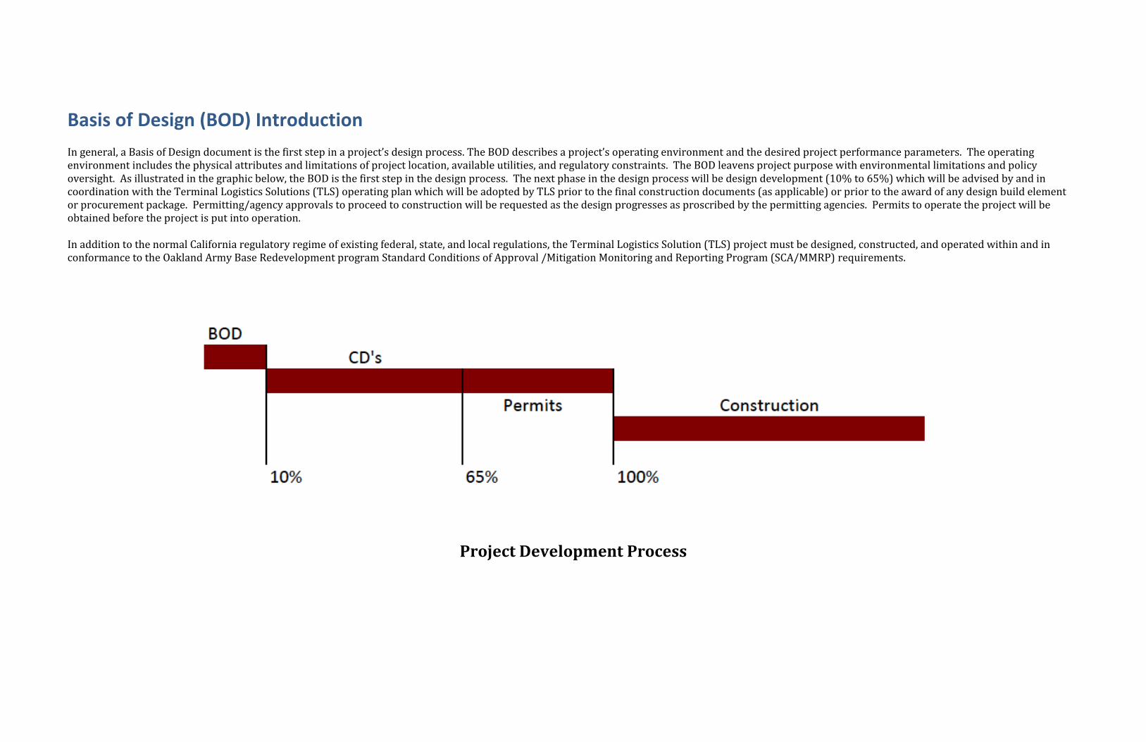
Basis of Design (BOD) Introduction In general, a Basis of Design document is the first step in a project’s design process. The BOD describes a project’s operating environment and the desired project performance parameters. The operating environment includes the physical attributes and limitations of project location, available utilities, and regulatory constraints. The BOD leavens project purpose with environmental limitations and policy oversight. As illustrated in the graphic below, the BOD is the first step in the design process. The next phase in the design process will be design development (10% to 65%) which will be advised by and in coordination with the Terminal Logistics Solutions (TLS) operating plan which will be adopted by TLS prior to the final construction documents (as applicable) or prior to the award of any design build element or procurement package. Permitting/agency approvals to proceed to construction will be requested as the design progresses as proscribed by the permitting agencies. Permits to operate the project will be obtained before the project is put into operation. In addition to the normal California regulatory regime of existing federal, state, and local regulations, the Terminal Logistics Solution (TLS) project must be designed, constructed, and operated within and in conformance to the Oakland Army Base Redevelopment program Standard Conditions of Approval /Mitigation Monitoring and Reporting Program (SCA/MMRP) requirements.
Project Development Process
Basis of DesignOakland Bulk and Oversized Terminal
California Capital Investment Group
Preliminary Engineering
Port of Oakland, Oakland, CAJuly 16, 2015
Basis of DesignOakland Bulk and Oversized Terminal
This page is intentionally left blank.
ii | July 16, 2015
Basis of DesignOakland Bulk and Oversized Terminal
Contents
1 Basis of Design ................................................................................................................................... 1
12.1 Rail Systems ........................................................................................................................... 1212.1.1 Train and Railcar Data ............................................................................................... 12
12.2 Site Preparation....................................................................................................................... 1312.2.1 Clearing and Grubbing ............................................................................................... 1312.2.2 Temporary Spill Containment and Erosion Control.................................................... 1312.2.3 Ground Improvement ................................................................................................. 1312.2.4 Demolition .................................................................................................................. 1312.2.5 Earthworks ................................................................................................................. 1312.2.6 Hazardous Materials .................................................................................................. 13
12.5 Site Drainage........................................................................................................................... 14
12.6 Water Systems ........................................................................................................................ 1512.6.1 Materials ..................................................................................................................... 1512.6.2 Valves......................................................................................................................... 1512.6.3 Cross-Connections and Inter-Connections ................................................................ 16
12.7 Fire Protection ......................................................................................................................... 1612.7.1 General....................................................................................................................... 1612.7.2 Piping, Fire Hydrants and Hose Cabinets .................................................................. 16
12.8 Wastewater Systems............................................................................................................... 1612.8.1 Pipe Materials ............................................................................................................. 1712.8.2 Force Mains................................................................................................................ 1712.8.3 Water Pumping........................................................................................................... 17
12.14 Operating and Maintenance Vehicles ..................................................................................... 18
iv | July 16, 2015
Basis of DesignOakland Bulk and Oversized Terminal
Tables
Table 3-1. Service Life .................................................................................................................................. 3Table 5-1. Material Properties....................................................................................................................... 4Table 6-1. Terminal Throughput ................................................................................................................... 5Table 8-1. Design Vessels ............................................................................................................................ 5Table 9-1. Railcar Dumper Requirements .................................................................................................... 6
July 16, 2015 | v
Basis of DesignOakland Bulk and Oversized Terminal
This page is intentionally left blank.
vi | July 16, 2015
Basis of DesignOakland Bulk and Oversized Terminal
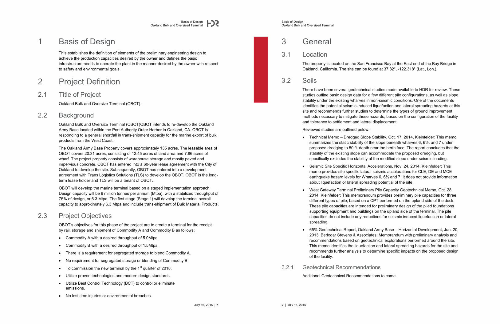
1 Basis of Design This establishes the definition of elements of the preliminary engineering design to achieve the production capacities desired by the owner and defines the basic infrastructure needs to operate the plant in the manner desired by the owner with respect to safety and environmental goals.
2 Project Definition
2.1 Title of ProjectOakland Bulk and Oversize Terminal (OBOT).
2.2 Background Oakland Bulk and Oversize Terminal (OBOT)OBOT intends to re-develop the Oakland Army Base located within the Port Authority Outer Harbor in Oakland, CA. OBOT is responding to a general shortfall in trans-shipment capacity for the marine export of bulk products from the West Coast.
The Oakland Army Base Property covers approximately 135 acres. The leasable area of OBOT covers 20.31 acres, consisting of 12.45 acres of land area and 7.86 acres of wharf. The project property consists of warehouse storage and mostly paved and impervious concrete. OBOT has entered into a 60-year lease agreement with the City of Oakland to develop the site. Subsequently, OBOT has entered into a development agreement with Trans Logistics Solutions (TLS) to develop the OBOT. OBOT is the long-term lease holder and TLS will be a tenant of OBOT.
OBOT will develop the marine terminal based on a staged implementation approach. Design capacity will be 9 million tonnes per annum (Mtpa), with a stabilized throughput of 75% of design, or 6.3 Mtpa. The first stage (Stage 1) will develop the terminal overall capacity to approximately 6.3 Mtpa and include trans-shipment of Bulk Material Products.
2.3 Project ObjectivesOBOT’s objectives for this phase of the project are to create a terminal for the receiptby rail, storage and shipment of �o������� and ���������� as follows:
� C�������� with a desired throughput of 5.0Mtpa.
� ���������� with a desired throughput of 1.5Mtpa.
� There is a requirement for segregated storage to blend ���������.
� No requirement for segregated storage or blending of �����������
� To commission the new terminal by the 1st quarter of 2018.
� Utilize proven technologies and modern design standards.
� Utilize Best Control Technology (BCT) to control or eliminateemissions.
� No lost time injuries or environmental breaches.
July 16, 2015 | 1
Basis of DesignOakland Bulk and Oversized Terminal
3 General
3.1 LocationThe property is located on the San Francisco Bay at the East end of the Bay Bridge in Oakland, California. The site can be found at 37.82°, -122.318° (Lat., Lon.).
3.2 SoilsThere have been several geotechnical studies made available to HDR for review. These studies outline basic design data for a few different pile configurations, as well as slope stability under the existing wharves in non-seismic conditions. One of the documents identifies the potential seismic-induced liquefaction and lateral spreading hazards at this site and recommends further studies to determine the types of ground improvement methods necessary to mitigate these hazards, based on the configuration of the facility and tolerance to settlement and lateral displacement.
Reviewed studies are outlined below:
� Technical Memo – Dredged Slope Stability, Oct. 17, 2014, Kleinfelder: This memo summarizes the static stability of the slope beneath wharves 6, 6½, and 7 under proposed dredging to 50 ft. depth near the berth face. The report concludes that the stability of the existing slope can accommodate the proposed dredging, but specifically excludes the stability of the modified slope under seismic loading.
� Seismic Site Specific Horizontal Accelerations, Nov. 24, 2014, Kleinfelder: This memo provides site specific lateral seismic accelerations for CLE, DE and MCE earthquake hazard levels for Wharves 6, 6½ and 7. It does not provide information about liquefaction or lateral spreading potential of the site.
� West Gateway Terminal Preliminary Pile Capacity Geotechnical Memo, Oct. 28, 2014, Kleinfelder: This memorandum provides preliminary pile capacities for three different types of pile, based on a CPT performed on the upland side of the dock. These pile capacities are intended for preliminary design of the piled foundations supporting equipment and buildings on the upland side of the terminal. The pile capacities do not include any reductions for seismic induced liquefaction or lateral spreading.
� 65% Geotechnical Report, Oakland Army Base – Horizontal Development, Jun. 20, 2013, Berlogar Stevens & Associates: Memorandum with preliminary analysis and recommendations based on geotechnical explorations performed around the site. This memo identifies the liquefaction and lateral spreading hazards for the site and recommends further analysis to determine specific impacts on the proposed design of the facility.
3.2.1 Geotechnical Recommendations
Additional Geotechnical Recommendations to come.
2 | July 16, 2015
Basis of DesignOakland Bulk and Oversized Terminal
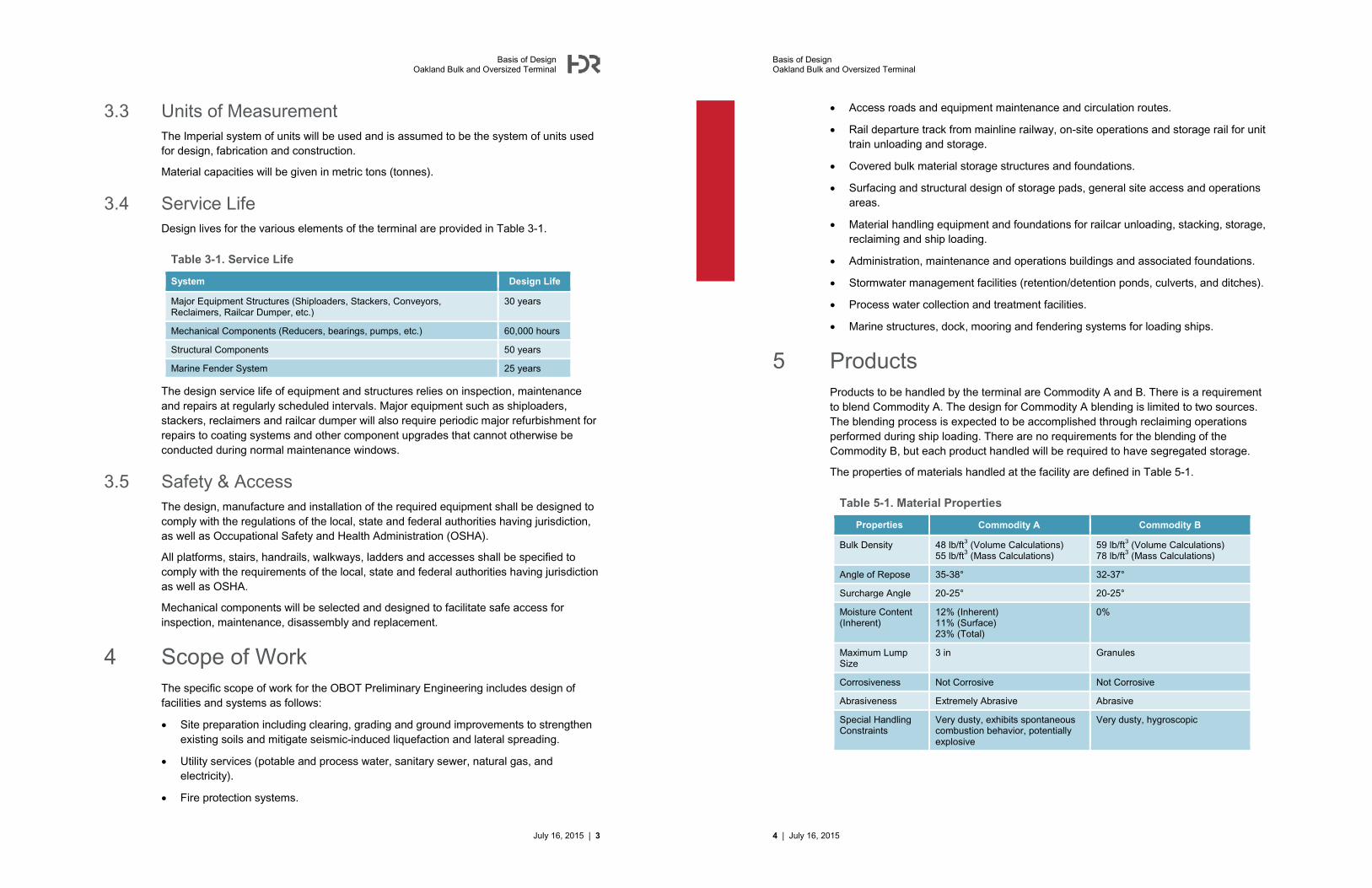
3.3 Units of MeasurementThe Imperial system of units will be used and is assumed to be the system of units used for design, fabrication and construction.
Material capacities will be given in metric tons (tonnes).
3.4 Service LifeDesign lives for the various elements of the terminal are provided in Table 3-1.
Table 3-1. Service Life
System Design Life
Major Equipment Structures (Shiploaders, Stackers, Conveyors, Reclaimers, Railcar Dumper, etc.)
The design service life of equipment and structures relies on inspection, maintenance and repairs at regularly scheduled intervals. Major equipment such as shiploaders, stackers, reclaimers and railcar dumper will also require periodic major refurbishment for repairs to coating systems and other component upgrades that cannot otherwise be conducted during normal maintenance windows.
3.5 Safety & AccessThe design, manufacture and installation of the required equipment shall be designed to comply with the regulations of the local, state and federal authorities having jurisdiction,as well as Occupational Safety and Health Administration (OSHA).
All platforms, stairs, handrails, walkways, ladders and accesses shall be specified to comply with the requirements of the local, state and federal authorities having jurisdiction as well as OSHA.
Mechanical components will be selected and designed to facilitate safe access for inspection, maintenance, disassembly and replacement.
4 Scope of WorkThe specific scope of work for the OBOT Preliminary Engineering includes design offacilities and systems as follows:
� Site preparation including clearing, grading and ground improvements to strengthen existing soils and mitigate seismic-induced liquefaction and lateral spreading.
� Utility services (potable and process water, sanitary sewer, natural gas, and electricity).
� Fire protection systems.
July 16, 2015 | 3
Basis of DesignOakland Bulk and Oversized Terminal
� Access roads and equipment maintenance and circulation routes.
� Rail departure track from mainline railway, on-site operations and storage rail for unittrain unloading and storage.
� Covered bulk material storage structures and foundations.
� Surfacing and structural design of storage pads, general site access and operationsareas.
� Material handling equipment and foundations for railcar unloading, stacking, storage,reclaiming and ship loading.
� Administration, maintenance and operations buildings and associated foundations.
� Stormwater management facilities (retention/detention ponds, culverts, and ditches).
� Process water collection and treatment facilities.
� Marine structures, dock, mooring and fendering systems for loading ships.
5 ProductsProducts to be handled by the terminal are ���������and �. There is a requirement to blend ���������. The design for ���������blending is limited to two sources.The blending process is expected to be accomplished through reclaiming operations performed during ship loading. There are no requirements for the blending of the����������, but each product handled will be required to have segregated storage.
The properties of materials handled at the facility are defined in Table 5-1.
Table 5-1. Material Properties
Properties ��������� ����������
Bulk Density 48 lb/ft3 (Volume Calculations)55 lb/ft3 (Mass Calculations)
Very dusty, exhibits spontaneous combustion behavior, potentially explosive
Very dusty, hygroscopic
4 | July 16, 2015
Basis of DesignOakland Bulk and Oversized Terminal
6 ThroughputOBOT intends to develop the marine terminal based in phases per Table 6-1.
Table 6-1. Terminal Throughput
Properties (Estimated)
C�������� 5.0 MMTPA
���������� 1.5 MMTPA
A preliminary spreadsheet simulation has been developed as a separate document.
7 Hours of OperationThe terminal will operate three 8-hour shifts a day, 362 days a year.
8 Marine8.1 General
A new mooring and berthing system will be constructed at the existing wharf (Wharf 7) capable of handling Capesize vessels. The proposed mooring and berthing system will be independent of the existing wharf, and will utilize breasting dolphins with fender panels and mooring dolphins with quick release mooring hooks. The dolphins will utilize steel pipe piles with cast-in-place concrete pile caps. There will also be two in-water arc shaped runways to support the quadrant loaders, founded on steel pipe piles. The pivot point supporting the tail end of the quadrant loaders will be supported on piles driven within the footprint of the existing wharf. The pivot support structure will have an independent pile supported foundation and be isolated from the existing timber wharf structure.
8.2 Design VesselsDesign vessel information is provided in Table 8-1.
Dredging Depth No Dredging No Dredging No Dredging1
1 Capesize ships, due to the existing 51 feet of draft with no plans for dredging, will be lightly loaded to an approximate maximum of 130,000 tonnes.
July 16, 2015 | 5
Basis of DesignOakland Bulk and Oversized Terminal
8.3 Mooring operationsNo mooring operations studies are proposed at this stage of the project and it is assumed that Capesize vessels can be moved into position to moorage facilities that will be designed to accept the design vessel.
8.4 Dredging No dredging is proposed to increase the design draft conditions. However, maintenance dredging will be required to maintain the design draft at the berth.
9 Mechanical
9.1 General Mechanical equipment will be selected based on modern material handling systems utilizing automation where reasonable to increase efficiency. Conveyance systems will be designed to Conveyor Equipment Manufacturers Association (CEMA) standards.
The mechanical systems will include:
� Railcar unloading equipment.
� Stacking, reclaiming and storage equipment.
� Conveyors for feeding, stacking and reclaiming.
� Ship loading equipment.
9.2 Railcar DumpersRequirements for the railcar dumpers can be found in Table 9-1.
Table 9-1. Railcar Dumper Requirements
Properties ��������� ����������
Type Bottom Dump Bottom Dump
Railcars North American Covered HopperCars1
North American Closed Top Hopper Cars
Gross Weight 130 tonnes 130 tonnes
Net Capacity 110 tonnes 110 tonnes
Number of Dumpers:
1 1
Railcar Positioning Method
Switching Locomotive or Indexer Switching Locomotive or Indexer
Design Dump Cycle Time
See Simulation See Simulation
1 Removable, fiberglass covers
6 | July 16, 2015
Basis of DesignOakland Bulk and Oversized Terminal
9.3 Conveyance
9.3.1 Troughed Belt Conveyors
���������
���������conveyors will be 48 or 84 in. equipped with 45° CEMA class C6 or E7idlers, troughed fabric belts, electric drive units and remote gravity take-ups and amaximum angle of 15 degrees. Where practical, drive units will be located at groundlevel with vehicle access. All conveyors will be housed in fully-enclosed galleries withsingle sided walkways and designed with ample access to tail pulleys and other criticalareas for maintenance.
����������
���������� conveyors will be 48 in. equipped with 35° CEMA class C6 idlers, troughed fabric belts, electric drive units and remote gravity take-ups and a maximumangle of 15 degrees. Where practical, drive units will be located at ground level withvehicle access. All conveyors will be housed in fully-enclosed galleries with single sided walkways and designed with ample access to tail pulleys and other critical areasfor maintenance.
9.3.2 Pipe Conveyors
Pipe conveyors will transport material from the railcar dumper to storage. The pipe conveyor will be ø23 in., equipped with electric drive units and gravity take-ups. The pipe conveyor will be of a self-carrying design that includes a single-sided walkway, top cover and expanded metal guarding along each side.
9.3.3 High-Angle Conveyors
High angle conveyors will be used to move material from the unloading pit to the pipe conveyors. The high-angle conveyors will be approximately 72 in. wide with 16 in. tall side walls equipped with electric drive units, automatic take-up and will be fully enclosed.
9.4 Contaminated MaterialContaminated product diverters will be included to remove material from the reclaim belts, between the storage buildings and shiploaders.
9.5 Storage
9.5.1 ���������Material will be stored in a series of covered longitudinal stockpiles. Stacking to the longitudinal stockpiles will be accomplished by the use of an overhead conveyor andtripper.
The ��������� storage capacities are:
1. Pile 1 105,0001 tonnes total
105,0001 tonnes live
July 16, 2015 | 7
Basis of DesignOakland Bulk and Oversized Terminal
2. Pile 2 75,0001 tonnes total
75,0001 tonnes live
Material will be manually reclaimed from the longitudinal stockpiles by dozers into aseries of dozer traps.1 In the case of segregated storage piles within the storage building, storage building 1 will have an estimated capacity of 84,000 tonnes, building 2 will have an estimated capacity of 55,000 tonnes.
9.5.2 ����������Material will be stored in a concrete storage dome(s). The storage dome(s) will be filledfrom the top and include a dust collection system.
The ���������� storage capacities are:
1. Dome 1 60,000 tonnes total
50,000 tonnes live
Material will be reclaimed from the storage dome(s) by gravity onto a series of reclaim conveyors in above ground tunnels underneath the dome(s).
9.6 Sampling
9.6.1 ���������Three-stage automatic sampling will take place on the outgoing product flows at the East shiploader.
9.6.2 ����������Automatic sampling is not required for the ���������� system.
9.7 Shiploading
9.7.1 ���������Shiploading will be accomplished with the use of dual telescoping quadrant shiploaders. Each shiploader will be equipped with loading spoons for hatch trimming. The shiploaders will be design to accommodate wash down of system between shipments.
9.7.2 ����������Shiploading will be accomplished with the use of a fixed, shuttling, slewing shiploader,utilizing a cascade type loading chute.
9.7.3 Shiploader control
Shiploaders will be controlled by remote control boxes from the decks of the ships, with backup control stations located on the shiploaders.
8 | July 16, 2015
Basis of DesignOakland Bulk and Oversized Terminal
9.7.4 Shiploader Chute/Spout Maintenance
Over the dock access will be provided for cleaning and maintaining loading chutes and spouts.
9.8 Dust Control
9.8.1 ���������Dust will be controlled by:
� Dry fog and/or water sprays at the covered railcar dumper building.
� Covered bulk material storage buildings.
� Enclosed transfers.
� Enclosed/Covered conveyors.
� Dry fog and/or water sprays at transfer points and stockpiles.
9.8.2 ����������Dust will be controlled by cartridge style, pulse-jet, dust collectors or bin vents:
� Unloading boots, enclosed hopper and dust collection at the covered railcar dumperbuilding.
� Enclosed storage domes with dust collection.
� Enclosed conveyor transfers.
� Covered conveyors.
� Dust Collection at transfer points and shiploader, as required.
� Dust collectors will be provided with rotary air locks.
10 Structural
10.1 General Structural design and development of loads will be based on the California Building Code and ASCE 7. It is anticipated that soil conditions will require ground improvements and pile supported foundations for all major equipment and storage buildings to mitigate settlement and seismic hazards associated with liquefaction.
Design of the marine structures will be in accordance with ASCE/COPRI 61-14 and utilize non-linear seismic analysis methods in the detailed design phase. It is assumed that any construction activities utilizing or affecting the existing wharf will be further investigated, and may include the need for a structural condition assessment and analysis of the existing elements for the temporary loads associated with mobile crane outriggers and any other construction loads. It is also anticipated that some lighter structures may be supported directly by the existing wharves which could potentially require wharf repairs depending on the outcome of the condition assessment.
July 16, 2015 | 9
Basis of DesignOakland Bulk and Oversized Terminal
10.2 Live LoadsThe vehicular/access lanes of the dock and trestle will be designed to an HS20-44highway load, or a 20T mobile crane (whichever controls based on span length). Conveyor galleries and access platforms will be designed for a 60psf live load.
10.3 Wind LoadsDesign wind speed: Vult=110 mph (Exp. C, Risk Category II) per Figure 1609A of the California Building Code.
10.4 Vessel LoadsMooring and berthing loads for the dock and fender system will be based on Capesize vessels (Approximately 180,000 DWT) Mooring and spring line loads for detailed design will be based on specialized mooring analysis software (OPTIMOOR or similar).
Berthing loads for the fender system and breasting dolphins will assume a vessel approach speed of 0.50 fps (normal to the berth face) and 10 degree approach angle.
10.5 Seismic LoadsSeismic design of the upland structures and foundations will be based on the International Building Code (IBC) and ASCE 7. The following site-specific design parameters were included in the 65% geotechnical report by Berlogar Stevens & Associates listed in Section 3.2:
� Ss: 1.5
� S1: 0.6
� SMS: 1.35
� SM1: 1.44
� SDS: 0.9
� SD1: 0.96
*Above seismic parameters based on Site Class ‘E’
Seismic design of the marine structures will be based on the performance-based analysis methods of ASCE/COPRI 61-14. The three seismic performance levels will be as follows:
� Operating Level Earthquake (OLE):
� 1 in 72 year event (50% probability of exceedance in 50 years)
� Contingency Level Earthquake (CLE):
� 1 in 475 year event (10% probability of exceedance in 50 years)
� Design Earthquake (DE):
� 2/3 of Full Maximum Considered Earthquake (MCE); MCE defined as (2% probability of exceedance in 50 years) per ASCE 7
10 | July 16, 2015
Basis of DesignOakland Bulk and Oversized Terminal
11 Electrical and Controls
11.1 ElectricalUtility electrical power will be delivered to the site by two independent 12.47kV three-phase systems owned by the Port of Oakland or PG&E. At the Point-of-Delivery on the site, utility power will be received at main service electrical room with metering and isolation/protection. Electrical power will be distributed on site at 12.47kV three-phase in an open-loop system (site electrical distribution loop) to area electrical rooms located throughout the site.
Each area electrical room will distribute electrical power to equipment, motors, lighting etc. through unit substation transformers that will step down the voltage to service voltages required.
Electrical Shore Power and Communications will be provided at a vault mounted on the wharf to interface with docked ships, allowing them to connect to the electrical grid (cold ironing).
Power and control cable will be jacketed armored cable suitable for heavy industrial environments. Non-armored cable may be used where installed in cable duct or other enclosed raceway. Cables will be distributed in cable tray where possible.
Uninterruptible Power Supplies (UPSs) will be used to power the Site Control System, select lighting and other services required to be in service after the loss of electrical power.
Drives for conveyors and selected other equipment will include AC motors controlled by Variable Frequency Drives (VFDs).
Generators will be used as the back-up or emergency power source for services that are required to be in service under loss of electrical power, which are too large for a UPS system.
LED lighting will be the primary technology used for lighting throughout the site.
11.2 ControlsThe Site Control System will be based on a PLC/SCADA system. A dual-redundant hot backup processor system will be used for the PLC. The SCADA system will provide a graphical and data analysis interface for operation.
The PLC system will utilize remote input/output racks closed to the field instruments, devices and final control elements. The control system will communicate via Ethernet over fiber optic cables to remote racks.
Input/output (I/O) devices will be 4-20mA for analog signals, 24VDC or 120VAC for discrete (on/off) signals. Specialty devices such as RTDs to measure temperature will use RTD signal directly to the PLC I/O.
The SCADA system main Graphical User Interfaces (GUIs) will be located in a Central Control Room located at the Administration Building. Operator Interface Terminals (OITs) will be provided at site area locations where required.
July 16, 2015 | 11
Basis of DesignOakland Bulk and Oversized Terminal
Control will be either Remote or Local. Remote control is operational control through the PLC/SCADA system via the GIUs or OITs. Local control is manual control through Local Control Panels (LCPs) that may include pushbuttons, selector switches, pilot lights, drive interface terminals, etc.
Major equipment, for example shiploaders, may have on-board, stand-alone control systems. These control systems will be specified to be compatible with the Site Control System. Communications to stand-alone equipment will be Ethernet over fiber optic cable. The Site Control System will monitor and/or provide supervisory control through the communications link. Exceptions would be any emergency signals that would require hard-wiring.
The rail unloading facilities will have an independent control system. This system will be compatible with and linked to the downstream control system. Only when the downstream control system is configured for material transfers, and verified, will the rail unloading system be allowed to initiate transfers.
12 Infrastructure
12.1 Rail SystemsA rail system, designed to meet with BNSF and UP Industrial Track Standards will be used for receipt and processing of unit trains. There will be an arrival and departure spur from the mainline to the facility. Unit trains will be processed in approximately 26-car segments through discharging into a below grade dumping pit and conveyance system.The 26-car segments will be pulled or pushed through the dumping stations either by a switching locomotive or an indexer, which will be evaluated during preliminary engineering.
12.1.1 Train and Railcar Data
The design calls for incoming trains of 104 railcars to be split in and handled on 26railcars “ladder type” storage tracks. ��������� railcars are expected to be bottom dump aluminum construction, closed top hopper cars, with gross weight of 130 tonnes, cargo capacity of approximately 110 tonnes. ���������� railcars are expected to be steel construction, closed top, bottom dump hopper cars, each with approximately 90tonnes of cargo capacity.
���������cars will be bottom hopper, rapid discharge style cars, with removable, fiberglass covers.
���������� cars will be 60 ft. long, closed top hopper cars. Variable configurationsand numbers of hoppers are anticipated. The ���������� cars will be unloaded in a stationary position. Pneumatic gate opening/closing devices will be used.
12 | July 16, 2015
Basis of DesignOakland Bulk and Oversized Terminal
12.2 Site Preparation
12.2.1 Clearing and Grubbing
Clearing, grubbing and top soil stripping is to be done only where required leaving as much of the existing vegetation as practicable. The design will:
� Establish vegetation clearing, grubbing, and over-stripping requirements.
� Determine the applicable regulations and restrictions for disposal of materialsthrough discussions with appropriate authorities.
12.2.2 Temporary Spill Containment and Erosion Control
The design will:
� Establish the regulations surrounding the disposal of site runoff into off-site watercourses through discussions with the appropriate authorities.
� Provide the necessary containment facilities for products of erosion and oil spillsoriginating from construction activities and equipment operation, etc.
� Provide appropriate best management practices to treat site runoff and preventsiltation of natural water courses.
12.2.3 Ground Improvement
Ground improvements will be based on Geotechnical Engineers recommendations, itis assumed that some type of ground improvement will be required for the ���������storage building for support of the ���������stockpile. An appropriate recommendation for the type and extent of ground improvement will be determined,after additional geotechnical studies, during detail engineering.
12.2.4 Demolition
Demolition is being done by the Owner and is assumed to be completed prior to the start of site work
12.2.5 Earthworks
Re-grading of the site to create appropriate base grades for the new facilities. It is assumed that grading will be driven by the requirements of operations of the new facilities and other design constraints rather than trying to achieve an earthwork balance.
The design will establish the approximate extent of excavation, import and export required in accordance with the recommendations of the Owner’s Geotechnical Engineer. Surplus material will be disposed of as directed by the Owner’s representative.Disposal of contaminated soil is not anticipated.
12.2.6 Hazardous Materials
The site may contain toxic or hazardous materials. If present, these materials andsubsequent mitigation strategies will be established by others, with a specific focus on
July 16, 2015 | 13
Basis of DesignOakland Bulk and Oversized Terminal
determining areas of potential soil contamination and establishing the nature and extent of remediation required.
The design will assume no hazardous materials findings.
12.3 SurfacingThe design will account for surfacing materials in and around the new facilities to allow for the movement of personnel and equipment, and to direct surface runoff water away from facilities to drains and ditches. In general, the surfacing will include:
� Pavement where vehicular or access ways warrant.
� Gravel for pedestrian paths and maintenance areas.
� Grass or vegetation for low use areas and landscaped areas.
12.4 Roads/Vehicular AccessThe design will specify on-site access roads that connect buildings and maintained facilities. Roads will be designed in accordance with the following specifications:
� Maximum grade: 10%
� Minimum centerline radius: 50 ft.
� Minimum traffic (traveled way) width (2 lanes): 16.5 ft.
� Minimum vertical clearance: 16 ft.
� Cross slopes: 2%
Pavement thickness design is to be provided by Owner’s Geotechnical Engineer.Additional turning radii accommodations for large delivery equipment and mobile maintenance equipment may be considered for access ways depending on operations requirements identified to the Engineer by the Owner.
12.5 Site DrainageSite drainage for stormwater surface runoff will be facilitated through the use of stormwater management facilities that could include open channel and underground gravity conveyance systems, stormwater pump stations/force main systems, and stormwater detention/infiltration and treatment systems. The design will establish the appropriate methodologies for sizing stormwater management facilities based on local requirements for stormwater quality and flow control.
Low Impact Development (LID) techniques will be considered for accomplishing local stormwater quality and flow control standards. LID techniques may include reducing impervious surfaces where practical and utilizing infiltration where feasible as determined by the Owner’s Geotechnical Engineer. Excess stormwater will discharge through an approved and permitted outlet. Opportunities for storing and reusing stormwater for process or dust suppression may be considered depending economic feasibility.
14 | July 16, 2015
Basis of DesignOakland Bulk and Oversized Terminal
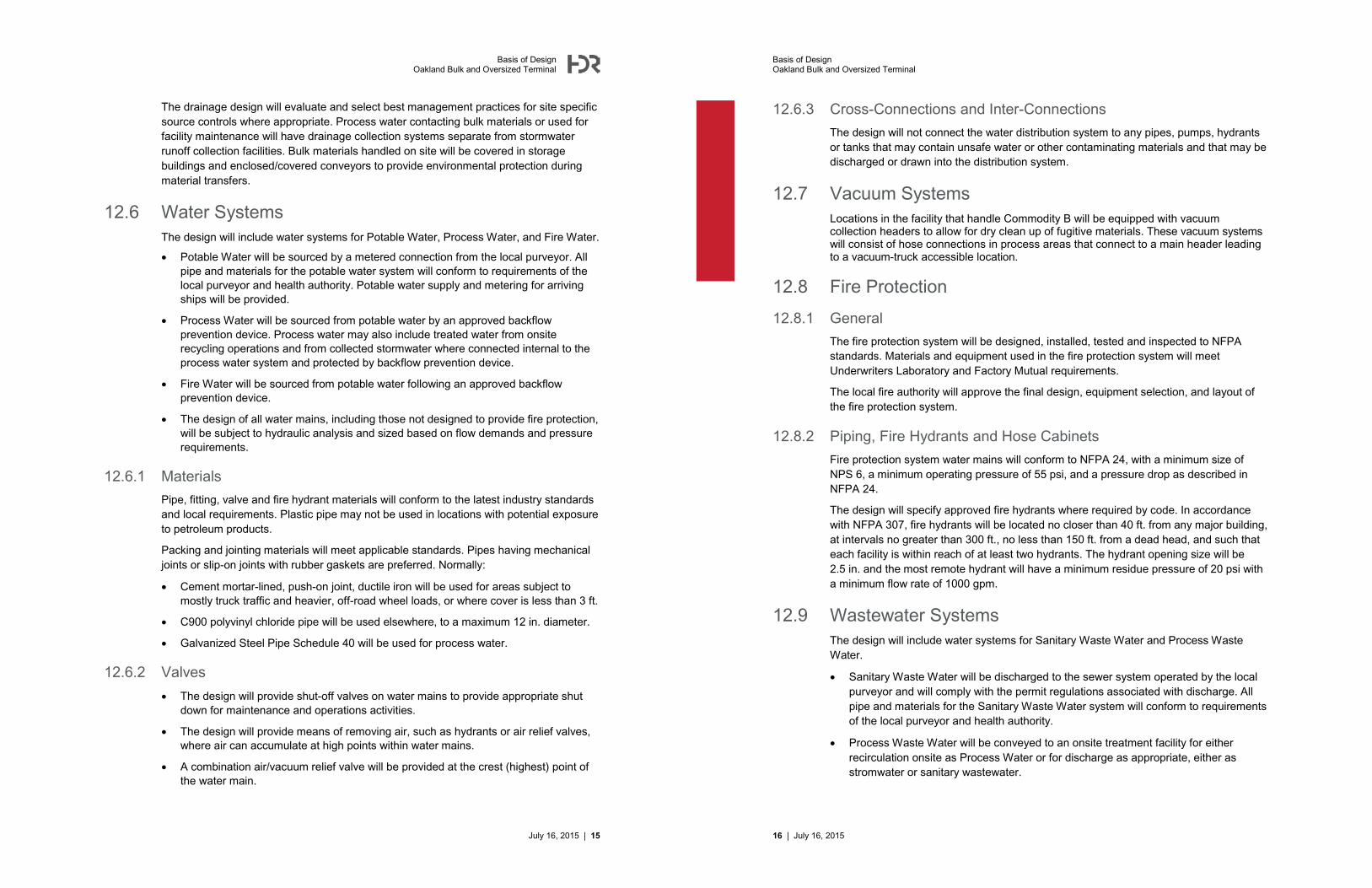
The drainage design will evaluate and select best management practices for site specific source controls where appropriate. Process water contacting bulk materials or used forfacility maintenance will have drainage collection systems separate from stormwater runoff collection facilities. Bulk materials handled on site will be covered in storage buildings and enclosed/covered conveyors to provide environmental protection during material transfers.
12.6 Water SystemsThe design will include water systems for Potable Water, Process Water, and Fire Water.
� Potable Water will be sourced by a metered connection from the local purveyor. All pipe and materials for the potable water system will conform to requirements of the local purveyor and health authority. Potable water supply and metering for arriving ships will be provided.
� Process Water will be sourced from potable water by an approved backflow prevention device. Process water may also include treated water from onsite recycling operations and from collected stormwater where connected internal to the process water system and protected by backflow prevention device.
� Fire Water will be sourced from potable water following an approved backflow prevention device.
� The design of all water mains, including those not designed to provide fire protection, will be subject to hydraulic analysis and sized based on flow demands and pressure requirements.
12.6.1 Materials
Pipe, fitting, valve and fire hydrant materials will conform to the latest industry standards and local requirements. Plastic pipe may not be used in locations with potential exposure to petroleum products.
Packing and jointing materials will meet applicable standards. Pipes having mechanical joints or slip-on joints with rubber gaskets are preferred. Normally:
� Cement mortar-lined, push-on joint, ductile iron will be used for areas subject to mostly truck traffic and heavier, off-road wheel loads, or where cover is less than 3 ft.
� C900 polyvinyl chloride pipe will be used elsewhere, to a maximum 12 in. diameter.
� Galvanized Steel Pipe Schedule 40 will be used for process water.
12.6.2 Valves
� The design will provide shut-off valves on water mains to provide appropriate shut down for maintenance and operations activities.
� The design will provide means of removing air, such as hydrants or air relief valves, where air can accumulate at high points within water mains.
� A combination air/vacuum relief valve will be provided at the crest (highest) point of the water main.
July 16, 2015 | 15
Basis of DesignOakland Bulk and Oversized Terminal
12.6.3 Cross-Connections and Inter-Connections
The design will not connect the water distribution system to any pipes, pumps, hydrants or tanks that may contain unsafe water or other contaminating materials and that may be discharged or drawn into the distribution system.
12.7 Vacuum SystemsLocations in the facility that handle ����������will be equipped with vacuum collection headers to allow for dry clean up of fugitive materials. These vacuum systemswill consist of hose connections in process areas that connect to a main header leadingto a vacuum-truck accessible location.
12.8 Fire Protection
12.8.1 General
The fire protection system will be designed, installed, tested and inspected to NFPA standards. Materials and equipment used in the fire protection system will meet Underwriters Laboratory and Factory Mutual requirements.
The local fire authority will approve the final design, equipment selection, and layout of the fire protection system.
12.8.2 Piping, Fire Hydrants and Hose Cabinets
Fire protection system water mains will conform to NFPA 24, with a minimum size of NPS 6, a minimum operating pressure of 55 psi, and a pressure drop as described in NFPA 24.
The design will specify approved fire hydrants where required by code. In accordance with NFPA 307, fire hydrants will be located no closer than 40 ft. from any major building, at intervals no greater than 300 ft., no less than 150 ft. from a dead head, and such that each facility is within reach of at least two hydrants. The hydrant opening size will be 2.5 in. and the most remote hydrant will have a minimum residue pressure of 20 psi with a minimum flow rate of 1000 gpm.
12.9 Wastewater SystemsThe design will include water systems for Sanitary Waste Water and Process Waste Water.
� Sanitary Waste Water will be discharged to the sewer system operated by the localpurveyor and will comply with the permit regulations associated with discharge. Allpipe and materials for the Sanitary Waste Water system will conform to requirementsof the local purveyor and health authority.
� Process Waste Water will be conveyed to an onsite treatment facility for eitherrecirculation onsite as Process Water or for discharge as appropriate, either asstromwater or sanitary wastewater.
16 | July 16, 2015
Basis of DesignOakland Bulk and Oversized Terminal
� The design of all wastewater mains will be subject to hydraulic analysis and sized based on flow demands and pressure requirements.
� Underground wastewater pipelines will be designed with at least 3 ft. of cover.
12.9.1 Pipe Materials
The design will use the following pipe materials, which will be selected to suit the physical and chemical properties of the liquids they convey:
� Fiberglass reinforced plastic pipe: Pipe lengths will be joined using bell-and-spigot joints or a butt-and-strap technique. Bell-and-spigot pipe joint gaskets will be made of appropriate synthetic materials to suit the liquid being carried by the pipe.
� High-density polyethylene pipe: Pipe lengths will be joined using butt fusion methods or flanges.
� Polyvinyl chloride pipe: Pipe lengths will be joined using bell-and-spigot gasketed joints or solvent welds.
� Stainless steel (SAE grade 304) or epoxy-lined and coated mild steel pipe (for exposed pipelines): Pipe lengths will be welded or joined using flanged or Victaulic couplings.
� Sewer pipelines will be designed with at least 2 ft. of cover below sub-grade where they pass under heavily traveled roads.
12.9.2 Force Mains
Force mains will be designed to maintain a minimum fluid velocity of 3 ft/s and a maximum velocity of 11.5 ft/s. Force mains will aim to rise continuously toward an outlet without local high points. An automatic air relief valve will be provided at each high point in the force main to prevent air locks.
A combined air/vacuum relief valve will be provided at the crest (highest point) of each force main. Force mains will enter the gravity system at a point not higher than 2 ft. above the flow line of the receiving manhole.
12.9.3 Water Pumping
Pumps shall be provided for locations where pumping is required.
Submersible pumps shall be used where possible and designed to handle slurry flow with a solid weight concentration of up to 1%.
Pumps shall be controlled by level instruments and preference shall be given to pumps that can run dry.
12.10 Cable TrenchesIt is assumed that duct banks will convey main underground systems outside of areas where they can be conveyed by above ground structures on cable trays.
July 16, 2015 | 17
Basis of DesignOakland Bulk and Oversized Terminal
12.11 Security and FencingTo the west side of the facility is a public access area. There will be fencing and screening placed along this area to provide control access and provide visual separation.
12.11.1 Parking
Parking for ILWU, administrative staff and visitors will be provided outside of secure facility.
12.12 Office and Maintenance FacilityThere will be an administration/maintenance building located between the entrance and the stockpile area. The administration/maintenance building will be approximately7,500 ft2.
12.13 Dock OfficeAn approximate 200 ft2 dock office with Internet, Ethernet, HMI and phone access.
12.14 Gangway AccessGangway access to provide safe access to all ships will be provided.
12.15 Operating and Maintenance VehiclesMobile equipment such as forklifts, wheel loaders, boom trucks, welders, service trucks, pickups, and light utility vehicles are assumed to be required, but will be specified and provided by the terminal.
18 | July 16, 2015
X
X
X
X
X
35+00
40+00
WEST GATEWAYCENTRAL GATEWAY
MH-1 "TRUE-UP"PARCEL 14.60 AC
1
2
WE
ST B
UR
MA
RO
AD
B-10
WHARF 6 (BERTH 9)
WH
AR
F 5
(B
ER
TH
10)
WHARF 6.5 (BERTH 8)
WHARF
7 (B
ERTH 7
)
CITY TO PORT LEASE A2
CITY TO PORT LEASE A1
99
88
90WATER TREATMENT FACILITY
CALTRANS STORAGE STRUCTURE
CALTRANS TRAILERS
TLS BULK MATERIAL HANDINGPROJECT
PRIVATE ROAD
A
C
TLS AREA OVERLAY ON MASTER PLAN
CITY OF OAKLAND, ALAMEDA COUNTY, CALIFORNIA
1:200 7/30/2015 X-5
AD-0005.0133596
COMMENTDATEREV
DATE:
JOB NO.
SCALE:ARCHITECTURAL DIMENSIONS
JAMES HEILBRONNER510-463-8300300 FRANK H. OGAWA PLAZA, SUITE 375OAKLAND, CA 94612
OAB02
CHECKED BY:
DRAWN BY:CAT. NO
INV. NO. 1 1J. ARMADA
J. ARMADA
GRAPHIC SCALE
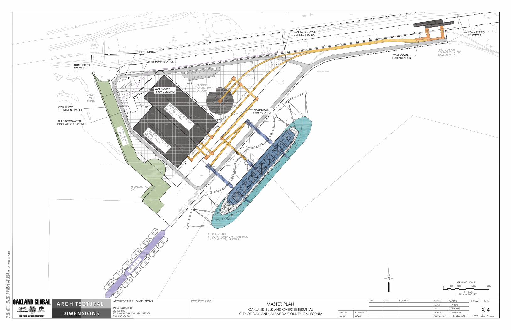
MASTER PLAN OAKLAND BULK AND OVERSIZE TERMINAL
CITY OF OAKLAND, ALAMEDA COUNTY, CALIFORNIA
1" = 100'7/27/2015 X-4
AD-0004.0133560
COMMENTDATEREV
DATE:
JOB NO.
SCALE:ARCHITECTURAL DIMENSIONS
JAMES HEILBRONNER510-463-8300300 FRANK H. OGAWA PLAZA, SUITE 375OAKLAND, CA 94612


![RADON BIKES OVERSIZE MAGAZINE 01/2011 [english]](https://static.documents.pub/doc/80x56/568c53971a28ab4916bb6d3c/radon-bikes-oversize-magazine-012011-english.jpg)


![RADON BIKES OVERSIZE MAGAZINE 03/2010 [english]](https://static.documents.pub/doc/80x56/568c518b1a28ab4916b3149a/radon-bikes-oversize-magazine-032010-english.jpg)


