Draft, Pre- Decisional, Do Not Cite or Quote, For Discussion Purposes Only RED HILL TANKS 14, 17 AND 18 NON-DESTRUCTIVE EXAMINATION PLAN This Non-Destructive Evaluation (NDE) Plan is being provided pursuant to EPA letters of 7 July 2017 and 10 August 2017 regarding Conditional Approval of Scope of Work for Destructive Testing, Section 5.3.2 of the Red Hill AOC-SOW. In summary, the NDE for Tanks 14, 17, and 18, is one of the many requirements of the on-going tank inspection, repair and maintenance (TIRM) program for the Red Hill Storage Tanks. The Request for Proposal (RFP) for the TIRM of Tanks 14, 17, and 18 was released in June 2016. NDE is just one of many proposal requirements in the RFP. After reviewing all proposals submitted, the government selected CB & I. Excerpts of the following pertinent documents related to NDE, some of which are procurement sensitive are attached. 1. NDE Excerpts from Tank 14, 17, and 18 Inspection and Repair Technical Approach 2. NDE Excerpts from Contractor Inspection and Test Plan 3. NDE Excerpts from Design Quality Control Plan 4. Excerpts from Ch. 4 of the AOC-SOW TIRM Report 5. J. J. Nyholt, "Alternative NDT Techniques for Prudhoe Bay Pipeline Failures," The NDT Technician, pp. 1-6, July 2007. (Reference No. 2 in Ch. 4 of the TIRM Report) The method of NDE was chosen as a portion of an overall contractor proposal. Below is a summary of reasons the proposal was selected. 1 Privileged, Highly Procurement Sensitive, Source Selection Information, See FAR 2.101 and 3.104, 5 U.S.C. 552(b)(3), 5 USC 552(b)(5).
Transcript
Draft, Pre- Decisional, Do Not Cite or Quote, For Discussion Purposes Only
RED HILL TANKS 14, 17 AND 18 NON-DESTRUCTIVE EXAMINATION PLAN
This Non-Destructive Evaluation (NDE) Plan is being provided pursuant to EPA letters of 7 July 2017 and 10 August 2017 regarding Conditional Approval of Scope of Work for Destructive Testing, Section 5.3.2 of the Red Hill AOC-SOW.
In summary, the NDE for Tanks 14, 17, and 18, is one of the many requirements of the on-going tank inspection, repair and maintenance (TIRM) program for the Red Hill Storage Tanks. The Request for Proposal (RFP) for the TIRM of Tanks 14, 17, and 18 was released in June 2016. NDE is just one of many proposal requirements in the RFP. After reviewing all proposals submitted, the government selected CB & I. Excerpts of the following pertinent documents related to NDE, some of which are procurement sensitive are attached.
1. NDE Excerpts from Tank 14, 17, and 18 Inspection and Repair Technical Approach 2. NDE Excerpts from Contractor Inspection and Test Plan 3. NDE Excerpts from Design Quality Control Plan 4. Excerpts from Ch. 4 of the AOC-SOW TIRM Report 5. J. J. Nyholt, "Alternative NDT Techniques for Prudhoe Bay Pipeline Failures," The NDT
Technician, pp. 1-6, July 2007. (Reference No. 2 in Ch. 4 of the TIRM Report)
The method of NDE was chosen as a portion of an overall contractor proposal. Below is a summary of reasons the proposal was selected.
1
Privileged, Highly Procurement Sensitive, Source Selection Information, See FAR 2.101 and 3.104, 5 U.S.C. 552(b)(3), 5 USC 552(b)(5).
Draft, Pre- Decisional, Do Not Cite or Quote, For Discussion Purposes Only
2
Privileged, Highly Procurement Sensitive, Source Selection Information, See FAR 2.101 and 3.104, 5 U.S.C. 552(b)(3), 5 USC 552(b)(5).
Draft, Pre- Decisional, Do Not Cite or Quote, For Discussion Purposes Only
PRIOR EXPERIENCE WITH THIS PROCESS AT RED HILL
The government’s past experience with the NDE contractor and their equipment in previous Red Hill tank inspections is described in Chapter 4-2 SUMMARY OF THE PROCESS SELECTED of the AOC-SOW TIRM Report. Key points are summarized below.
a. NDT was performed on Tank 5 by TesTex as a subcontractor to WGS. TesTex conducted NDT on Red Hill Tank 5 from 18 August to 24 September 2010. At this point TesTex had previously completed similar-type inspections on Red Hill Tanks 2, 6, 15, and 20 using many of the same TesTex technicians. The same supervising engineer led the inspection team on all previous tanks. He had developed a standard procedure and order of work, which was used for Tank 5.
b. The inspection was performed with the TesTex developed TS-2000 NDT Multi-channel System (for plate scanning) using the principles of the Low Frequency Electromagnetic Technique) and the Hawkeye 2000 System (for weld testing) focusing on surface and subsurface cracking and pinholes. All defected areas found with the above-mentioned TesTex equipment were backed up and sized using regular Ultrasonic Technique, Ultrasonic Shear Wave Technique and Magnetic Particle Technique. The Ultrasonic Shear Wave Technique was an additional service used which measured the depth of detected weld defects, provided they were oriented in a position that could be tested.
c. LFET was used to scan and determine liner plates’ thickness and back-side corrosion thereon, in all portions of the tank body (bottom, lower dome, barrel shell, extension, and upper dome). Specific indications that were detected using LFET were pitting, general corrosion, back-side corrosion, and thinned areas. The LFET devices, TS-2000 and the Falcon Mark II 2000 are adaptable for use on tank wall vertical surfaces such as the barrel at Red Hill Tank 5, and both devices can be used on the tank floor as well. Low-Frequency Electromagnetic Testing (LFET) equipment, capabilities, and reliability:
1) The TesTex Falcon Mark II 2000 is designed to perform LFET inspection on the ferrous surfaces of fuel tanks. It has LFET sensors mounted on wheels. In conjunction with the Viper Crawler system, it can also be used to scan walls. a) Can detect metal plate surface crack, back-side corrosion, and as little as 5%
wall thinning. Tank plates can be covered 100% due to “a sixteenth inch modular swath containing 32 probe heads”. Depending on the model, a swath up to 330 mm (13 in) can be covered in one pass on a flat surface. The incoming signal is processed and translated into percentages of wall loss based on calibration tables.
b) Probability-of-detection (POD) curves, describing the probability of detecting a flaw versus the flaw size, were not supplied in the reports; according to a published article about nondestructive techniques used to inspect a pipeline in Alaska [Attachment 5], LFET demonstrated 100% POD at 25% wall loss on defects such as isolated pitting at a 3:1 aspect ratio. The LFET equipment used to produce the data for the POD analysis in Alaska was manufactured and operated by TesTex.
3
Draft, Pre- Decisional, Do Not Cite or Quote, For Discussion Purposes Only
2) The TesTex TS-2000 is a handheld LFET device with scanners mounted on small wheels. Due to its small size, it can be easily used to inspect tank walls, like the vertical barrel regions of Red Hill tanks. Furthermore, it has scanners that have a diameter of only a few millimeters, enabling it to detect pitting and other micro-scale flaws. a) 8-channel scanner; multiple sensors allow for greater sensing of cracks and
pits. The received signal is transformed into percent-wall-loss data with calibration tables, and can be connected to a computer for further analysis. Because the sensors have diameters of only a few millimeters, tiny defects like pits can be detected, and scanning in general is in high resolution. In addition, hydrogen damage, erosion, cracks, chemical gouging, and corrosion cells are detectable as well. Up to 3,000 linear feet can be inspected by one team of certified technicians in a single 10-12 hour shift in a Red Hill tank. Generally, inspection is performed in two-person teams. TesTex was able to increase the efficiency during the inspection by 65% by having only one person in each basket. They were able to have more scans per man-hour due to less “wait” time if there were two people in the basket.
b) Detection Accuracy: The lock-in amplifier is capable of measuring very low level signals in the microvolt range and can measure small phase angle changes of a fraction of a degree, even in the presence of a considerable amount of noise. This system, when used in conjunction with the calibration standards: partial and through-wall pitting, gradual wall thinning, Hydrogen damage, etc. and their respective calibration curves, allows us to measure small gradual wall losses on the order of 10%, pits of diameter 0.062" (1.57mm), and vibration/fret wear of five volume percent.
3) According to TesTex, LFET devices can find both delamination and wall loss. However, TesTex’s testing procedures do not involve distinguishing those two kinds of flaws with LFET; instead, ultrasonic testing is used to tell these flaws apart as it backs up LFET scans.
d. Balanced-Field Electromagnetic Testing (BFET) was used to inspect welds. Equipment, Capabilities, and Reliability:
1) The TesTex Hawkeye 2000 is a technology based on eddy current principles of electromagnetic techniques which is able to detect flaws on and immediately below the surfaces of welds. It is advantageous to use for locations that are difficult to reach. In one pass, it can assess both sides of a butt weld, covering 101 mm (4 in). Features it can detect include porosity, slag, undercuts, and cracks. As for cracks in particular, they can be found up to 3 mm or 0.125 inch deep from the surface of carbon steel. The technique is quantitative and can be used to size the dept and length of cracks. It works much faster than magnetic-particle and dye-penetrant testing, capable of scanning up to 0.3 m/s (1 ft/s).
e. Longitudinal Ultrasonic Testing (UT) was used for “proofing areas”. In addition, TesTex stated that longitudinal UT was implemented to confirm suspected defect areas found with the Falcon 2000 and TS 2000 and to give wall remaining at these spots. Equipment, Capabilities, and Reliability:
4
Draft, Pre- Decisional, Do Not Cite or Quote, For Discussion Purposes Only
1) The Krautkramer USN-60 has 15-Hz to 6-kHz pulse repetition frequency, 250-kHz to 25-MHz frequency range; steel scanning range of 1 mm to 28 m (0.040” to 1100”). Echoes can be adjusted using Multiple Curve Distance Amplitude Curve/Time Corrected Gain. Up to 16 points can be recorded. Test modes include dual-, through-, and pulse echo-transmission.
2) The Krautkramer DMS-2 is an ultrasonic device used to find the thickness of a metal. According to TesTex, the Krautkramer DMS-2 is used for longitudinal-wave testing only. It can measure thickness independently of material defects, and can measure and display thicknesses of metals and their coatings separately at the same time. It can detect back-side corrosion and minor pitting. The probe is zeroed automatically according to inspection conditions. Its measuring range is 0.2 mm to 635 mm (0.008” to 25.00”) for steel.
f. Shearwave Ultrasonic Testing (SWUT) was used to inspect all possible locations of weld flaws in the tank that had been scanned using BFET. SWUT operates on the same principle as longitudinal-wave UT, but the materials’ particles move perpendicular to the direction of the sound waves. Shearwave testing is also called angle beam testing. It is used to determine flaws’ dimensions and their depth within a material, primarily for defects that are not parallel to the material’s surface. Equipment, Capabilities, and Reliability:
1) Krautkramer USN-60: 15-Hz to 6-kHz pulse repetition frequency, 250-kHz to 25-MHz frequency range; steel scanning range of 1 mm to 28 m (0.040” to 1100”). Echoes can be adjusted using Multiple Curve Distance Amplitude Curve/Time Corrected Gain. Up to 16 points can be recorded. Test modes include dual-, through-, and pulse echo-transmission.
2) Avenger EZ: Range of 0.1016-8636 mm (0.4”-340”). 300-Hz pulser. Calibration modes are delay, range, zero, and velocity. 500-kHz to 15-MHz frequency range. Automatic probe recognition, single- or dual-element. Angle, delay, contact, single, and dual operational modes. Simultaneous display of A-trace and B-scan possible.
Attachment 5 is the article referenced in Chapter 4 of the TIRM report that describes a third party evaluation of the probability of detection of the LFET technology.
5
Draft, Pre- Decisional, Do Not Cite or Quote, For Discussion Purposes Only
ATTACHMENT 1 TANK 14, 17, AND 18 INSPECTION TECHNICAL APPROACH
Attachment 1-1
Privileged, Highly Procurement Sensitive, Source Selection Information, See FAR 2.101 and 3.104, 5 U.S.C. 552(b)(3), 5 USC 552(b)(4), 10 U.S.C. 2305(g).
Draft, Pre- Decisional, Do Not Cite or Quote, For Discussion Purposes Only
Attachment 1-2
Privileged, Highly Procurement Sensitive, Source Selection Information, See FAR 2.101 and 3.104, 5 U.S.C. 552(b)(3), 5 USC 552(b)(4), 10 U.S.C. 2305(g).
Draft, Pre- Decisional, Do Not Cite or Quote, For Discussion Purposes Only
Attachment 1-3
Privileged, Highly Procurement Sensitive, Source Selection Information, See FAR 2.101 and 3.104, 5 U.S.C. 552(b)(3), 5 USC 552(b)(4), 10 U.S.C. 2305(g).
Draft, Pre- Decisional, Do Not Cite or Quote, For Discussion Purposes Only
ATTACHMENT 2 NDE EXCERPTS FROM THE CONTRACTOR INSPECTION AND TEST PLAN
OVERVIEW
Attachment 2-1
Privileged, Highly Procurement Sensitive, Source Selection Information, See FAR 2.101 and 3.104, 5 U.S.C. 552(b)(3), 5 USC 552(b)(4), 10 U.S.C. 2305(g).
Draft, Pre- Decisional, Do Not Cite or Quote, For Discussion Purposes Only
Attachment 2-2
Privileged, Highly Procurement Sensitive, Source Selection Information, See FAR 2.101 and 3.104, 5 U.S.C. 552(b)(3), 5 USC 552(b)(4), 10 U.S.C. 2305(g).
Draft, Pre- Decisional, Do Not Cite or Quote, For Discussion Purposes Only
Attachment 2-3
Privileged, Highly Procurement Sensitive, Source Selection Information, See FAR 2.101 and 3.104, 5 U.S.C. 552(b)(3), 5 USC 552(b)(4), 10 U.S.C. 2305(g).
Attachment 2-4
Privileged, Highly Procurement Sensitive, Source Selection Information, See FAR 2.101 and 3.104, 5 U.S.C. 552(b)(3), 5 USC 552(b)(4), 10 U.S.C. 2305(g).
Privileged, Highly Procurement Sensitive, Source Selection Information, See FAR 2.101 and 3.104, 5 U.S.C. 552(b)(3), 5 USC 552(b)(4), 10 U.S.C. 2305(g).
Privileged, Highly Procurement Sensitive, Source Selection Information, See FAR 2.101 and 3.104, 5 U.S.C. 552(b)(3), 5 USC 552(b)(4), 10 U.S.C. 2305(g).
Privileged, Highly Procurement Sensitive, Source Selection Information, See FAR 2.101 and 3.104, 5 U.S.C. 552(b)(3), 5 USC 552(b)(4), 10 U.S.C. 2305(g).
Privileged, Highly Procurement Sensitive, Source Selection Information, See FAR 2.101 and 3.104, 5 U.S.C. 552(b)(3), 5 USC 552(b)(4), 10 U.S.C. 2305(g).
Privileged, Highly Procurement Sensitive, Source Selection Information, See FAR 2.101 and 3.104, 5 U.S.C. 552(b)(3), 5 USC 552(b)(4), 10 U.S.C. 2305(g).
Privileged, Highly Procurement Sensitive, Source Selection Information, See FAR 2.101 and 3.104, 5 U.S.C. 552(b)(3), 5 USC 552(b)(4), 10 U.S.C. 2305(g).
Privileged, Highly Procurement Sensitive, Source Selection Information, See FAR 2.101 and 3.104, 5 U.S.C. 552(b)(3), 5 USC 552(b)(4), 10 U.S.C. 2305(g).
2
Privileged, Highly Procurement Sensitive, Source Selection Information, See FAR 2.101 and 3.104, 5 U.S.C. 552(b)(3), 5 USC 552(b)(4), 10 U.S.C. 2305(g).
3
Privileged, Highly Procurement Sensitive, Source Selection Information, See FAR 2.101 and 3.104, 5 U.S.C. 552(b)(3), 5 USC 552(b)(4), 10 U.S.C. 2305(g).
4
Privileged, Highly Procurement Sensitive, Source Selection Information, See FAR 2.101 and 3.104, 5 U.S.C. 552(b)(3), 5 USC 552(b)(4), 10 U.S.C. 2305(g).
5
Privileged, Highly Procurement Sensitive, Source Selection Information, See FAR 2.101 and 3.104, 5 U.S.C. 552(b)(3), 5 USC 552(b)(4), 10 U.S.C. 2305(g).
6
Privileged, Highly Procurement Sensitive, Source Selection Information, See FAR 2.101 and 3.104, 5 U.S.C. 552(b)(3), 5 USC 552(b)(4), 10 U.S.C. 2305(g).
7
Privileged, Highly Procurement Sensitive, Source Selection Information, See FAR 2.101 and 3.104, 5 U.S.C. 552(b)(3), 5 USC 552(b)(4), 10 U.S.C. 2305(g).
8
Privileged, Highly Procurement Sensitive, Source Selection Information, See FAR 2.101 and 3.104, 5 U.S.C. 552(b)(3), 5 USC 552(b)(4), 10 U.S.C. 2305(g).
9
Privileged, Highly Procurement Sensitive, Source Selection Information, See FAR 2.101 and 3.104, 5 U.S.C. 552(b)(3), 5 USC 552(b)(4), 10 U.S.C. 2305(g).
10
Privileged, Highly Procurement Sensitive, Source Selection Information, See FAR 2.101 and 3.104, 5 U.S.C. 552(b)(3), 5 USC 552(b)(4), 10 U.S.C. 2305(g).
11
Privileged, Highly Procurement Sensitive, Source Selection Information, See FAR 2.101 and 3.104, 5 U.S.C. 552(b)(3), 5 USC 552(b)(4), 10 U.S.C. 2305(g).
Privileged, Highly Procurement Sensitive, Source Selection Information, See FAR 2.101 and 3.104, 5 U.S.C. 552(b)(3), 5 USC 552(b)(4), 10 U.S.C. 2305(g).
Privileged, Highly Procurement Sensitive, Source Selection Information, See FAR 2.101 and 3.104, 5 U.S.C. 552(b)(3), 5 USC 552(b)(4), 10 U.S.C. 2305(g).
2
Privileged, Highly Procurement Sensitive, Source Selection Information, See FAR 2.101 and 3.104, 5 U.S.C. 552(b)(3), 5 USC 552(b)(4), 10 U.S.C. 2305(g).
3
Privileged, Highly Procurement Sensitive, Source Selection Information, See FAR 2.101 and 3.104, 5 U.S.C. 552(b)(3), 5 USC 552(b)(4), 10 U.S.C. 2305(g).
Privileged, Highly Procurement Sensitive, Source Selection Information, See FAR 2.101 and 3.104, 5 U.S.C. 552(b)(3), 5 USC 552(b)(4), 10 U.S.C. 2305(g).
Draft, Pre- Decisional, Do Not Cite or Quote, For Discussion Purposes Only
ATTACHMENT 3 NDE EXCERPTS FROM THE CONTRACTOR DESIGN QUALITY CONTROL PLAN
Attachment 3-1
Privileged, Highly Procurement Sensitive, Source Selection Information, See FAR 2.101 and 3.104, 5 U.S.C. 552(b)(3), 5 USC 552(b)(4), 10 U.S.C. 2305(g).
Draft, Pre- Decisional, Do Not Cite or Quote, For Discussion Purposes Only
Attachment 3-2
Privileged, Highly Procurement Sensitive, Source Selection Information, See FAR 2.101 and 3.104, 5 U.S.C. 552(b)(3), 5 USC 552(b)(4), 10 U.S.C. 2305(g).
Draft, Pre- Decisional, Do Not Cite or Quote, For Discussion Purposes Only
Attachment 3-3
Privileged, Highly Procurement Sensitive, Source Selection Information, See FAR 2.101 and 3.104, 5 U.S.C. 552(b)(3), 5 USC 552(b)(4), 10 U.S.C. 2305(g).
Draft, Pre- Decisional, Do Not Cite or Quote, For Discussion Purposes Only
Attachment 3-4
Privileged, Highly Procurement Sensitive, Source Selection Information, See FAR 2.101 and 3.104, 5 U.S.C. 552(b)(3), 5 USC 552(b)(4), 10 U.S.C.
2305(g).
Draft, Pre- Decisional, Do Not Cite or Quote, For Discussion Purposes Only
ATTACHMENT 4 EXCERPTS FROM CH. 4 OF THE AOC-SOW TIRM REPORT
Attachment 4-1
Red Hill AOC SOW TIRM Report 11 Oct 2016
NAVY/DLA
Defense Logistics Agency (DLA)
Planning, programming, budgeting, and funding projects for maintenance, repair, minor construction, and environmental compliance for POL facilities
Fleet Logistics Center Pearl Harbor (FLCPH)
Red Hill operator. Logistics and supply-support services to US forces and allied forces in Mid-Pacific region
Naval Facilities Contracting team. Quality assurance, project management, and Engineering design management Command (NAVFAC) Engineering and Expeditionary Warfare Center (EXWC) Naval Facilities Engineering Command Hawaii (NAVFACHI)
Quality assurance, construction management, safety oversight
4-2 SUMMARY OF THE PROCESS SELECTED
4-2.1 Non-Destructive Testing (NDT) – Inspection NDT was performed on Tank 5 by TesTex as a subcontractor to WGS. TesTex conducted NDT on Red Hill Tank 5 from 18 August to 24 September 2010. At this point TesTex had previously completed similar-type inspections on Red Hill Tanks 2, 6, 15, and 20 using many of the same TesTex technicians. The same supervising engineer led the inspection team on all previous tanks. He had developed a standard procedure and order of work, which was used for Tank 5.
From Attachment T, TesTex Inspection Report on Red Hill Tank 5 dated 15 October 2010, Appendix A, Section 1.0, Introduction, the work is described as follows:
This inspection focused on 100% testing of the Floor, Lower Dome, Barrel, Extension, and Upper Dome areas. The inspection was performed with the TesTex developed TS-2000 NDT Multi-channel System (for plate scanning) using the principles of the Low Frequency Electromagnetic Technique) and the Hawkeye 2000 System (for weld testing) focusing on surface and subsurface cracking and pinholes. All defected areas found with the above-mentioned TesTex equipment were backed up and sized using regular Ultrasonic Technique, Ultrasonic Shear Wave Technique and Magnetic
4-2
Red Hill AOC SOW TIRM Report 11 Oct 2016
Particle Technique. The Ultrasonic Shear Wave Technique was an additional service used which measured the depth of detected weld defects, provided they were oriented in a position that could be tested.
4-2.1.1 Low-Frequency Electromagnetic Testing (LFET) An electromagnetic driver with two ends is placed on the surface of a metal, and a sensor is placed between the two ends of the driver. The driver emits a low-frequency (3-40 Hz) alternating-current signal, and the sensor detects the magnetic fields between the two poles of the driver. Flaws in the metal distort the magnetic fields; this distortion is recorded in the form of amplitude and phase deviations. The wider the flaw in the metal, the more sensors record shifts in the magnetic signal. The signal is then converted into percentages of material loss using numerical tables. Refer to Attachment T.
Equipment, Capabilities, and Reliability:
a. TesTex Falcon Mark II 20001
Description: This device is designed to perform LFET inspection on the ferrous surfaces of fuel tanks. It has LFET sensors mounted on wheels. In conjunction with the Viper Crawler system, it can also be used to scan walls. [1]
Capabilities: Can detect metal plate surface crack, back-side corrosion, and as little as 5% wall thinning [1]. Tank plates can be covered 100% due to “a sixteenth inch modular swath containing 32 probe heads” (Attachment T, Appendix A, Sub-Appendix C). The incoming signal is processed and translated into percentages of wall loss based on calibration tables. Probability-of-detection (POD) curves, describing the probability of detecting a flaw versus the flaw size, were not supplied in the WGS or TesTex reports. Depending on the model, a swath up to 330 mm (13 in) can be covered in one pass on a flat surface. [1]
Probability of Detection: POD curves, describing the probability of detecting a flaw versus the flaw size, were not supplied in the WGS or TesTex reports in Attachment T. However, according to a published article about nondestructive techniques used to inspect a pipeline in Alaska in
1 N.B.: The WGS portion of Attachment T mentions that the Falcon Mark II 2000 was used in LFET inspection at Red Hill Tank 5. However, the TesTex portion of the report discusses the device but does not state it was utilized.
4-3
Red Hill AOC SOW TIRM Report 11 Oct 2016
2006 [2], LFET demonstrated 100% POD at 25% wall loss on defects such as isolated pitting at a 3:1 aspect ratio. The LFET equipment used to produce the data for the POD analysis in Alaska was manufactured and operated by TesTex.
b. TesTex TS-2000 [3]2
Description: The TesTex TS-2000 is a handheld LFET device with scanners mounted on small wheels. The scanners do not contact tank surfaces [3]. Due to its small size, it can be easily used to inspect tank walls, like the vertical barrel regions of Red Hill tanks, unlike the Falcon Mark II 2000, which is heavier and can only inspect horizontal surfaces below it [1]. Furthermore, in contrast to the Falcon Mark II 2000, the TS-2000 has scanners that have a diameter of only a few millimeters, enabling it to detect pitting and other micro-scale flaws [3].
Capabilities: 8-channel scanner; multiple sensors allow for greater sensing of cracks and pits. As with the Falcon Mark II 2000, the received signal is transformed into percent-wall-loss data with calibration tables. It can be connected to a computer for further analysis (Attachment T). Because the sensors have diameters of only a few millimeters, tiny defects like pits can be detected, and scanning in general is in high resolution. In addition, hydrogen damage, erosion, cracks, chemical gouging, and corrosion cells are detectable as well. It operates at 10-Hz frequency or lower. Up to 3,000 linear feet can be inspected by one team of certified technicians in a single 10-12 hour shift in a Red Hill tank. [3] The number of technicians on this team varies depending on the number of flaws discovered, the condition of the tank surface, and the means of scaffolding. Generally, inspection is performed in two-person teams. TesTex was able to increase the efficiency during the inspection by 65% by having only one person in each basket. They were able to have more scans per man-hour due to less “wait” time if there were two people in the basket.
Detection Accuracy: From Attachment T, TesTex Inspection Report on Red Hill Tank 5 dated 15 October 2010, Appendix A Sub-Appendix C (Test Methods, Procedures and Equipment Description), Detection Accuracy:
2 N.B.: While the TesTex portion of Attachment T mentions that this device was used in Red Hill Tank 5 inspection, the WGS portion of the report does not mention the tool.
4-4
Red Hill AOC SOW TIRM Report 11 Oct 2016
The TesTex, Inc. developed lock-in amplifier is capable of measuring very low level signals in the microvolt range and can measure small phase angle changes of a fraction of a degree, even in the presence of a considerable amount of noise. This system, when used in conjunction with the calibration standards: partial and through-wall pitting, gradual wall thinning, Hydrogen damage, etc. and their respective calibration curves, allows us to measure small gradual wall losses on the order of 10%, pits of diameter 0.062" (1.57mm), and vibration/fret wear of five volume percent.
Items Inspected by LFET: Liner plates’ thickness and back-side corrosion thereon, in all portions of the tank body (bottom, lower dome, barrel shell, extension, and upper dome). Specific indications that were detected using LFET were pitting, general corrosion, back-side corrosion, and thinned areas. (Attachment T).
The LFET devices, TS-2000 and the Falcon Mark II 2000 are adaptable for use on tank wall vertical surfaces such as the barrel at Red Hill Tank 5, and both devices can be used on the tank floor as well. Attachment T does not specifically state which device, or if both devices, were used during the inspection.
According to TesTex, LFET devices can find both delaminations and wall loss. However, TesTex’s testing procedures do not involve distinguishing those two kinds of flaws with LFET; instead, ultrasonic testing is used to tell these flaws apart as it backs up LFET scans.
4-2.1.2 Balanced-Field Electromagnetic Testing (BFET) [4] An electromagnetic probe is placed near a metallic body. The deviation of the electromagnetic field is recorded; the vertical and horizontal components of the signal are phase-shifted to decrease the noise in the measured magnetic field (Attachment T).
Equipment, Capabilities, and Reliability: The TesTex Hawkeye 2000 is a technology based on eddy current principles of electromagnetic techniques which is able to detect flaws on and immediately below the surfaces of welds. It is advantageous to use for locations that are difficult to reach (Attachment T). Its frequency range is 5 Hz to 30 kHz, and in one pass, it can assess both sides of a butt weld, covering 101 mm (4 in). Features it can detect include porosity, slag, undercuts, and cracks. As for cracks in particular, they can be
4-5
Red Hill AOC SOW TIRM Report 11 Oct 2016
found up to 3 mm or 0.125 inch deep from the surface of carbon steel. The technique is quantitative and can be used to size the length and length of cracks. It works much faster than magnetic-particle and dye-penetrant testing, capable of scanning up to 0.3 m/s (1 ft/s). [4]
Items Inspected by BFET: Welds. Locations include lower dome-bottom interface, and the reinforcing pads and supports in the fixed drain line on the tank bottom (Attachment T). TesTex has stated that all welds in the tank were accessible to BFET.
4-2.1.3 Longitudinal Ultrasonic Testing (UT) General Description: A transducer emits high-frequency sound waves, also called ultrasonic waves, which are propagated through the material being scanned. The transducer records the time between when the waves are released and when the waves’ echoes are received into the transducer. If there is a flaw in the material, the time between release and echo is shortened (compared to the same amount of time for a non-flawed material) because the wave is propagated across a shorter distance. [5] In UT, particles in the material can collectively oscillate in response to the energy present in the sound waves being propagated. One way they can oscillate is by moving back and forth in the same direction as the sound waves, or in other words, in the longitudinal direction. [6]
Two devices were used for longitudinal UT: the Krautkramer USN-60 (Attachment T) and the Krautkramer DMS-2.
Equipment, Capabilities, and Reliability:
a. Krautkramer USN-60 The Krautkramer USN-60 (Attachment T) has 15-Hz to 6-kHz pulse repetition frequency, 250-kHz to 25-MHz frequency range; steel scanning range of 1 mm to 28 m (0.040” to 1100”). Echoes can be adjusted using Multiple Curve Distance Amplitude Curve/Time Corrected Gain. Up to 16 points can be recorded. Test modes include dual-, through-, and pulse echo-transmission. [7]
b. Krautkramer DMS-2 The Krautkramer DMS-2 is an ultrasonic device used to find the thickness of a metal. Both the WGS report and the TesTex report (Attachment T) mention this equipment. According to TesTex, the Krautkramer DMS-2 is used for longitudinal-wave testing only. It can measure thickness
4-6
Red Hill AOC SOW TIRM Report 11 Oct 2016
independently of material defects, and can measure and display thicknesses of metals and their coatings separately at the same time. It can detect back-side corrosion and minor pitting. The probe is zeroed automatically according to inspection conditions. Its measuring range is 0.2 mm to 635 mm (0.008” to 25.00”) for steel. Its test mode is only ultrasonic pulse-echo, but measurement modes include Dual Multi, MIN Capture, and dual- and single-element. [8]
Items Inspected:
a. Krautkramer USN-60 The WGS Tank 5 Inspection Report (Attachment T) states in paragraph 5.5 that “traditional ultrasonic longitudinal and shearwave inspection (was used) for proofing areas”. In addition, TesTex stated that longitudinal UT was implemented “to confirm suspected defect areas found with the Falcon 2000 and TS 2000 and to give wall remaining at these spots”.
b. Krautkramer DMS-2 The DMS-2 was used to prove up metal-thickness defects and corrosion defects that had initially been found using LFET (Attachment T).
4-2.1.4 Shearwave Ultrasonic Testing (SWUT) SWUT operates on the same principle as longitudinal-wave UT as described above, but the materials’ particles move perpendicular to the direction of the sound waves. [6] Shearwave testing is also called angle beam testing. It is used to determine flaws’ dimensions and their depth within a material, primarily for defects that are not parallel to the material’s surface (Attachment T).
Equipment, Capabilities, and Reliability (refer to the Baker Inspection Group portion of Attachment T):
a. Krautkramer USN-60 15-Hz to 6-kHz pulse repetition frequency, 250-kHz to 25-MHz frequency range; steel scanning range of 1 mm to 28 m (0.040” to 1100”). Echoes can be adjusted using Multiple Curve Distance Amplitude Curve/Time Corrected Gain. Up to 16 points can be recorded. Test modes include dual-, through-, and pulse echo-transmission. [7]
b. Avenger EZ Range of 0.1016-8636 mm (0.4”-340”). 300-Hz pulser. Calibration modes are delay, range, zero, and velocity. 500-kHz to 15-MHz frequency range.
4-7
Red Hill AOC SOW TIRM Report 11 Oct 2016
Automatic probe recognition, single- or dual-element. Angle, delay, contact, single, and dual operational modes. Simultaneous display of A-trace and B-scan possible. [9]
c. Panametrics Transducer: Part of UT equipment. d. Sonotech Couplant: Required to form couplant between transducer and
metal. e. American Society of Mechanical Engineers (ASME) Calibration Block:
Used to calibrate UT equipment.
Items Inspected (Attachment T):
All possible locations of weld flaws in the tank that had been scanned using BFET, in all regions other than the interface between the floor and lower dome. At the floor-lower dome interface, only the first six inches of welds between Course 1’s plates, immediately above the interface, were scanned using SWUT (Attachment T). Per TesTex, all welds that were accessible were inspected.
The reason shearwave scanning was performed on only the first six inches above the floor-lower dome interface was that this particular region of each Red Hill tank was believed to have a higher density of defects. The first Red Hill tank TesTex inspected, Tank 15, was found to have five defects at the interface between the floor and lower dome. These defects were discovered when Jurva Leak Testing, a subcontractor, injected helium behind Tank 15 and TesTex backed up those discoveries with their own instruments (more information on the Tank 15 contract work is in Chapter 10). TesTex stated that the higher concentration of defects in this region led to enhanced scrutiny, including the use of SWUT, on each tank’s floor-lower dome interface in subsequent Red Hill inspections.
Portions that are particularly noted as having been scanned by a specific instrument are described below and are mentioned in Attachment T as well.
1. Krautkramer USN-60 The WGS inspection report mentions that the Krautkramer USN-60 was used for SWUT to assess “Component integrity and wall thickness” (Section 4.0), but neither the TesTex report nor the reports by Baker Inspection Group mention it. Baker does mention that their angle beam ultrasonic inspections were performed with other equipment, namely, the
4-8
Red Hill AOC SOW TIRM Report 11 Oct 2016
Avenger EZ instrument, the Panametrics transducer, the Sonotech couplant, and the ASME calibration block (Attachment T).
2. Avenger EZ According to NDT Systems, the producer of the Avenger EZ, POD depends on the material’s grain structure as well as the transducer’s frequency and size. Baker Inspection Group was contacted but did not have Avenger EZ’s POD data.
4-3 TEST PERSONNEL AND CERTIFICATIONS
4-3.1 From Attachment R WGS Tank 5 and 17 Clean, Inspect, and Repairs Project Execution Work Plan, Section 5.0, Personnel Certifications:
KEY PERSONNEL
POSITION PERSONNEL NAME QUALIFICATIONS Project Manager /API 653 Inspector Tim Anderson B.S., Mechanical Engineering
API Std 653 Cert – #494 Tank Inspector
API 570 Cert – #1080 Piping Inspector API 510 Cert – #5034 Pressure
The NDT Technician A Quarter ly Publ icat ion for the NDT Pract it ioner
Focus Alternative NDT Techniques for Prudhoe Bay Pipeline Failures by John J. Nyholt
In August of 2006, a major petroleum company experienced the second loss of containment incident within the year on the pristine and environmentally sensitive North Slope of Alaska. Both leaks resulted from internal pitting corrosion on or near the bottom half of 0.85 m (34 in.) diameter transit pipelines. These lines transport 400 000 barrels of petroleum per day across 11 miles of Alaskan tundra.
The failure meant an immediate shutdown of approximately three percent of the petroleum supply to the lower 48 states. The potential for environmental disaster and the ensuing shutdown were quickly brought to the attention of environmental groups and jurisdictional authorities and, as quickly, to the attention of national media. Americans watched as the balance of environmental responsibility and energy dependence came to rest on the nondestructive testing (NDT) community. This article describes the investigation and application of fast-screening NDT techniques to ensure pipeline integrity and increase inspection efficiency.
Background
After shutdown, the U.S. Department of Transportation (USDOT) issued a legally binding Corrective Action Order (CAO) that mandated exclusive use of automated UT to examine the 4 to 8 o’clock sectors (radially designated) of all pipelines throughout the petroleum transit system. Inspection with UT would require the removal of polyurethane insulation panels and preparation of pipe
surfaces throughout the system. A machine applied anti-corrosion tape coating half of the pipeline created further difficulty. The number of insulation workers and ultrasonic technicians needed to accomplish the removal and inspection tasks was initially thought to be beyond what the North Slope could provide for in terms of temporary housing and travel logistics. At its height, NDT work alone would require 108 UT technicians working in alternating 12 h shifts.
The task before the petroleum company inspection team was to investigate alternative NDT corrosion screening techniques that could be submitted to the USDOT for possible
modification of the standing CAO. The fast-screening NDT techniques needed would have to detect 50% wall loss inside surface pits at a 3:1 aspect ratio. The consequences of another failure required 100% probability of detection (POD) of any discontinuity that met or exceeded the criteria.
Ultrasonic Method
During the inspections, UT was acknowledged as the only NDT method that could measure absolute remaining wall thickness within localized corrosion areas. All other methods were considered screening techniques subject to ultrasonic validation and measurement.
Each pipeline was segmented into 0.3 m (1 ft) inspection intervals, creating approximately 52 000 discrete areas to be screened for corrosion. Areas with less than 25% wall loss were ultrasonically tested to record minimum and average wall thicknesses within the segment. The team of 108 UT technicians inspected an average of 283 segments per day. Automated UT rates were 4.5 to 6.0 m
Focus continued on page 2.
Volume 6, Number 3 July 2007
Focus: Alternative NDT Techniques for Prudhoe Bay Pipeline Failures . . . 1
Crossword Challenge: Materials and Processes – Part I . . . . . . . . . . . . . . 10
A Publication of the American Society for Nondestructive Testing
CONTENTS
• •
• •
• •
• •
• •
• •
• •
• •
• •
• •
• •
• •
• •
• •
• •
• •
• •
• •
• •
• •
• •
• •
• •
• •
• •
• •
• •
• •
• •
FROM THE EDITOR
J ohn Nyholt’s article, “Alternative Techniques for Prudhoe Bay Pipeline Failures,” describes the inspection of two transit pipelines
crossing 11 miles of ecologically fragile tundra in Prudhoe Bay, Alaska as “a balance between environmental responsibility and energy dependence.” Indeed, the two lines deliver 400000 barrels of crude petroleum daily but within a tenuous eco-system where extensive and permanent damage can be done should petroleum leaks occur. Interior surfaces of the pipelines had become severely compromised, in some places, as much as 70 to 80% of wall thickness had been lost. As an NDT Corporate Level III Inspection Specialist, Nyholt’s job, along with the company Corrosion, Inspection and Chemicals Team, was to find and implement alternate NDT techniques to quickly and accurately detect the USDOT mandated 50% wall loss with 100% probability of detection. As he explains, it was a concerted effort from all members of the NDT community that resulted in positive outcome for both the environment and energy consumers.
Hollis Humphries, TNT Editor PO Box 28518, Columbus, Ohio 43228
(15 to 20 ft) per crew, per shift — unusually low, requiring additional manual scanning. Unlike automated UT, manual UT provides no ultrasonic image or permanent record of thickness measurement. Unless a successful alternative NDT technique could be found and accepted by the USDOT, the inspection of 52 000 areas was going to take 184 days.
Neither manual nor automated UT in its current configuration could inspect remaining wall thicknesses at welds, supports, or anchor points. Internal corrosion in these areas, however, was not considered preferential and inspection of them was deferred to the intelligent pig (robotic pipeline inspection gage inserted into the line) run that would follow external tests.
Axially orientated electromagnetic acoustic transducer (EMAT) technology was trial tested for pipe support touch point corrosion and was determined to detect greater than 30% wall loss from 0.5 m (20 in.) away from the support.
Tape stripping was later suspended in lieu of performing automated UT through 4 mm (0.16 in.) thick anti-corrosion tape, 8 mm (0.31 in.) at overlaps (Fig. 1). Ultrasonic performance on tape wrapped pipe was found to be fully equivalent to bare pipe inspection provided the tape was bonded and uniform. Areas where the tape wasn’t properly bonded were infrequent and were marked for tape removal and reinspection with automated UT. Absolute ultrasonic thickness measurements could be obtained by applying time of flight (TOF) delay correction factors of –10 mm (–0.39 in.) for single tape layers and –23 mm (–0.91 in.) for double tape layers. Ultrasonic echo-to-echo coating compensation mode was not used; pitting responses could interfere with proper UT signal gating. Ultrasonic testing amplitude sensitivity was established by 6 mm (0.25 in.) flat bottom hole (FBH) response on a bare calibration block followed by an applicable dB transfer value.
Isolated Single layer pit of tape
Double layer of tape
Figure 1. Automated ultrasonic testing image of isolated pit made through single and double layers of anti-corrosion tape .
Alternative corrosion screening techniques to complement or replace ultrasonic techniques had to maintain discontinuity detection thresholds while increasing NDT production tenfold. All commercial techniques were considered for application but, because of the highly isolated nature of material damage in the petroleum transit lines, the extreme consequences of another failure, and the inspection opportunities afforded by complete removal of the polyurethane insulation panels, only those techniques using a small, localized energy field were chosen. Real time data analysis was also a consideration as was the need to minimize further preparation of pipe surfaces.
At the end of preliminary assessments, four electromagnetic techniques were favored for fast screening of isolated pitting. Electromagnetic techniques do not require direct surface coupling, allow for real time inspection of large areas without labor-intensive surface preparation, and can speed up inspection without sacrificing test sensitivity or data quality. Of the four techniques considered as automated UT alternatives, only two were selected as short-term solutions. EMAT. Electromagnetic acoustic transducers (EMATs) use a permanent or electromagnetic driver/coil arrangement
(a) Carbon
steel
(b)
Crystal
Couplant
Ultrasonic wave
test object
Carbonsteeltest
Crystal
EMAT coil object circuit
Magnetic field
Ultrasonic wave
Lorentz force
Eddy current
Figure 2. Diagrams contrasting compression waves generated by (a) conventional ultrasonic testing with couplant and (b) waves generated by electromagnetic acoustic transduction.
to create various ultrasonic wave modes within carbon steel. Figure 2 demonstrates compression wave mode. In guided wave UT mode, EMAT typically generates a 5 cm (2 in.) wide sound beam that averages material volume and detects localized wall loss across the span of two permanent or electromagnetic driver/coil sensors. A mechanized scanner moves axially at a scan rate of roughly 75 to 150 mm (3 to 6 in.) per second. LFET. Low frequency electromagnetic testing (LFET) uses an electromagnetic driver/coil arrangement to create magnetic lines of flux through the volume of carbon steel material. Corrosion causes changes to nominal conditions of the field. Signals produced by these changes are received by a pickup coil measuring magnetic flux amplitude and phase (Fig. 3). EMAT technology is well established in industry and recognized in ASTM document E 18161 whereas LFET technology is newer. Similar to magnetic flux leakage in its sensor arrangement and usage, it offers electronic phase analysis and intuitive data interpretation.
Technique Trials
Performance of EMAT and LFET equipment was assessed under actual field conditions. A meticulous effort was made to disregard expectations based on preconceptions or manufacturer’s data. The 0.75 m (30 in.) decommissioned pipeline selected for trials was subjected
(a) Sensor
Steel plate
Magnetic lines of flux
Driver
Sweep direction
(b)
Steel plate
Sweep direction
Discontinuity
Figure 3. Electromagnetic driver creates (a) magnetic flux lines that reflect the nominal condition of a volume of steel with no discontinuities and (b) flux lines that deviate from the nominal condition to indicate a discontinuity.
to preliminary testing with intelligent pigging to provide known pitting corrosion areas for study. Computed radiography provided images of pitting. Ultrasonic thickness measurements with tape coating thickness compensation provided pit depth and aspect ratio information. A wide range of pit sizes, depths and morphologies were used to establish discontinuity depth detection thresholds and minimum detectectable discontinuity aspect ratios for each method (Figs. 4-7).
Field Trial Summary
EMAT. Performance attributes for EMAT testing were as follows (Fig. 5): • EMAT demonstrated 100% POD for
25% wall loss isolated pitting at a 3:1 aspect ratio in a 9 mm (0.375 in.) pipe wall [limited to T2 mode at 0.28 m (11 in.) probe spacing].
• EMAT can detect 30% wall loss at a 4:1 aspect ratio in a 9 mm (0.375 in.) pipe wall wrapped with anti-corrosion tape.
• Ten percent of anti-corrosion tape wrapped EMAT indications were false positives. False positives are not detrimental to the POD of EMAT testing but require rework with other NDT techniques.
• EMAT is susceptible to attenuation (as with all guided wave UT) with false calls due to outside or inside surface
Focus continued on page 4.
(a)
(b)
Figure 4. A typical example of corrosion pitting as it appears in (a) a computed radiographic image and (b) the same pitting example as it appears in an automated UT image made through anti-corrosion tape (68% wall loss).
07/2007 · The NDT Technician · 3
Focus continued from page 3.
boundary conditions. Internal sludge may deaden EMAT responses.
• A two-man crew using EMAT can inspect 300 m (1000 ft) per day, 150 m (500 ft) per day on tape wrapped pipe.
• EMAT provides a permanent image of the entire inspection segment.
• EMAT Indications must be followed up with UT thickness measurement.
LFET. The following LFET performance attributes were noted (Fig. 6): • LFET demonstrated 100% POD for
25% wall loss isolated pitting at a 3:1 aspect ratio.
• LFET performance remains unchanged on pipe wrapped with anti-corrosion tape.
• LFET has a false positive overcall rate of less than 1%.
• LFET can verify false positive EMAT indications.
• LFET performs better than automated
(a)
(b)
Figure 5. Field trial conducted for EMAT scanner shows (a) scanner installed on test pipe with pitting example described in Fig. 4 and (b) EMAT response to pitting sample (75% wall loss). Red line represents EMAT signal amplitude and blue line is time-of-flight. Saw-tooth pattern indicates tape bonding effects. Flat data segment to right of pitting response represents area where anti-corrosion tape was removed from pipeline for comparison purposes.
4 · 07/2007 · The NDT Technician
UT and EMAT on fluorocarbon resin repair tape.
• Inspection coverage for a two-man crew using handheld LFET instrument is limited to 60 m (200 ft) per day. With automation and improved probe fixtures, scanning production is increased to 3 m (10 ft) per min.
• LFET indications must be followed up with UT thickness measurement.
Field Implementation
After three weeks of NDT production and development, the performance boundaries of the alternative NDT screening techniques were established, although not yet approved by the USDOT. Until this time, hundreds of insulation strippers, tape scrapers, and ultrasonic technicians had been working simultaneously, around the clock with only one acceptable surface preparation and inspection technique. Even in August, fatigued workers were enduring working conditions that included cold, frequent rain, mud and standing water. Anticipating USDOT acceptance of data along with formal approval of the technology, advance NDT crews began to implement the alternative NDT techniques immediately upon approval by the NDT development team. Trial results were presented to USDOT officials and an independent NDT subject matter expert from the U.S. Department of Energy. Many officials (including the U.S. Secretary of Transportation) were in attendance to personally witness NDT technicians apply the alternative NDT techniques in repeated field performance trials. The alternative techniques were accepted by the USDOT and the CAO was modified after three weeks.
Figure 6. LFET response to pitting sample described in Figs. 4 and 5. Eight line scans below C-scan image indicate individual LFET sensor phase angle responses.
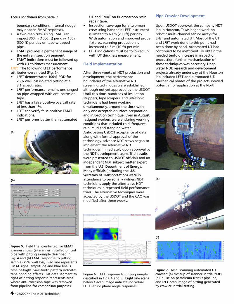
Pipe Crawler Development
Upon USDOT approval, the company NDT lab in Houston, Texas began work on robotic multi-channel sensor arrays for LFET and automated UT. Most of the UT and LFET work done to this point had been done by hand. Automated UT had continued to be inefficient. To obtain the needed tenfold increase in inspection production, further mechanization of these techniques was necessary. Deep water NDE research and development projects already underway at the Houston lab included LFET and automated UT. Mechanical phases of the projects showed potential for application at the North
(a)
(b)
(c)
Figure 7. Axial scanning automated UT crawler; (a) closeup of scanner in trial tests, (b) in use on petroleum transit pipeline, and (c) C-scan image of pitting generated by crawler in trial testing.
Slope site and were hastened into service in an ambitious three-week pipe-crawler construction program; all other work at two NDT development firms suspended until the machines could be fabricated.
Figure 7 shows an axial scanning automated UT crawler capable of continuous ultrasonic imaging of the 4 to 8 o’clock sectors of 0.85 m (34 in.) pipe. The two-piece clamshell assembly runs autonomously from pipe support to pipe
(a)
support, a distance of about 18 m (60 ft). At which point, the crawler is removed and redeployed in a 5 min. procedure for the next scan segment. The system runs at a rate of 9.75 m (32 ft) per hour with a single UT transducer and can increase the rate to 30 m (100 ft) per hour by implementing a four-transducer array and data merging software. Figure 7c shows a typical automated UT crawler data sample for a pitted pipe area.
(b)
By using an automated UT crawler, NDT technicians could now spend 90% of their time monitoring data collection from the comfort of a truck parked nearby. Areas that had been inaccessible because they were over bodies of water or at extended elevations could now be inspected without scaffolding. The potential for injuries or accidents related
Focus continued on page 6.
(c)
Figure 8. LFET axial scanning array; (a) closeup in trial configuration, (b) in use on petroleum transit pipeline, and (c) LFET data from pipe segment in trial configuration in 8a (compare to C-scan image of pitting in same pipe segment in Fig. 7c).
07/2007 · The NDT Technician · 5
• •
• •
• •
• •
• •
• •
• •
• •
• •
• •
• •
• •
• •
• •
• •
• •
• •
• •
• •
• •
• •
• •
• •
• •
• •
• •
• •
• •
• •
• • • • • • • • • • • • • •
Dear TNT Readers, Do you know what a UT level II needs to learn to get up to speed with phased array UT? Are you proficient in the use of shims and strips in magnetic particle inspection? Do you know how film and digital RT are different and the best application of each? Can you tell us about the envelope method of discontinuity sizing from API 5UE, or how to use acoustic emission in weld testing?
These are topics TNT would like you to write about. Consider becoming a TNT contributor. We’re an official journal of ASNT and as such, can offer you recert points for your contribution. Three points per published paper.
Contact the TNT Editor:
PO Box 28518, Columbus, OH 43228, (800) 222-2768 X206;
LFET is highly sensitive to sensor liftoff from the carbon steel surface yet can tolerate up to 6.35 mm (0.250 in.) in nonconductive coatings while maintaining discontinuity sensitivity. Figure 8 shows a mechanized 160-channel LFET axial scanning array capable of continuous and autonomous inspection. Each of the 20 sensor cars is equipped with a separate wheel system and is spring tensioned into a surface conforming array to control liftoff. The LFET scanner can test 18 m (60 ft) of pipe and provide real time data in just 6 min.
The 50% wall loss 3:1 pit aspect ratio discontinuity criteria mandated by the CAO worked in favor of EMAT and LFET screening tools. Each had a tendency to ignore pits below this criterion, thus reducing the time needed for data analysis. For example, both the LFET data shown in Fig. 8c and the automated UT data set in Fig. 7c are from the same section of pipeline. Only a few of these pits in the 3 m (10 ft) automated UT scan were of interest and those showed up in the LFET scan.
Findings
Necessity drives invention. The daunting task of large scale inspection in a remote area brought many NDT personnel together with just two goals. While under significant pressure, implement the
6 · 07/2007 · The NDT Technician
NDT techniques that were already known to work; then come up with new NDT techniques that could do the job better and faster. In less than a month, both goals had been accomplished. As the new inspection tools were pressed into service, both transit line inspection rates and data quality steadily improved, as did USDOT confidence in their ability to perform. The western petroleum transit line was approved for production. Three weeks later, the eastern petroleum transit line was returned to service. Despite challenging workloads and difficult living conditions, NDT technicians and NDT engineers had presented a concerted effort. The open discussion and free exchange of ideas had facilitated solutions for the set of problems that appeared with each new day and ultimately to the timely and environmentally responsible restoration of a vital natural resource (Fig. 9).
REFERENCES
1. ASTM E 1816, Standard Practice for Ultrasonic Examinations using Electromagnetic Acoustic Transducers (EMAT) Techniques. West Conshohocken, PA: ASTM International (2002).
John J. Nyholt is an NDE Corporate Level III, Inspection Specialist for BP North America. In conjunction with the BP Corrosion, Inspection, and Chemicals Team, he was the BP NDE Subject Matter Expert tasked with investigating alternative NDT corrosion screening techniques at Prudhoe Bay, AK in 2006. He also teaches NDT at San Jacinto College in Houston, Texas (281) 366-2933, <[email protected]>. TNT
Figure 9. Petroleum transit pipelines at Prudhoe Bay cross 11 miles of eco-sensitive Alaskan tundra. The eastern and western transit lines deliver a total of 400 000 barrels of North Slope crude petroleum to the lower 48 states on a daily basis.