DRAFT Quality Assurance (QA) Program Command Media Written by: Reviewed by: __ Electronically Signed _ ___Electronically Signed__ Paul Plumb Tyrone Jackson Approved by: Approved by: Approved by: ____________________ ____________________ _____________________ S. Dave Bouwer Rian Shelley W. Kent Tobiska
Transcript
DRAFT
Quality Assurance (QA) Program Command Media
Written by: Reviewed by: __ Electronically Signed _ ___Electronically Signed__ Paul Plumb Tyrone Jackson Approved by: Approved by: Approved by: ____________________ ____________________ _____________________ S. Dave Bouwer Rian Shelley W. Kent Tobiska
Quality Assurance (QA) Program
ORGANIZATIONAL MISSION ASSURANCE STANDARD (TIER 3)
Draft Revision: 0 Release: 04-15-2011 Effective: 04-15-2011 Copyright SET as an unpublished work. All rights reserved.
CORPORATE STANDARD
OBJECTIVE
This Standard defines SET’s approach for implementing a Quality Assurance (QA) Program. Through the interpretation and implementation of this Standard, SET projects will tailor the set of quality assurance activities to be commensurate with the unit-value/criticality of the development product. At the time this Standard was written, SET did not develop any very-high or ultra-high unit-value products.
Note: Guidance for generic product unit-value/criticality determinations are found in Figure 1.
APPLICABILITY
This Standard applies to all present and future SET sites/facilities, programs/projects, business lines/services, functional organizations/working groups, and employees/subcontractors, regardless of whether a CIRM Process has been contractually imposed.
Note: The terms and acronyms used in this Standard are defined in Section 9.
i
INTRODUCTION
The SET Quality Assurance Program Command Media is based on the QA Program defined in the AIAA Standard S-102.0.1. The SET QA program is managed independently of the acquisition or service project’s management chain. The lead Quality Engineer is assigned the responsibility and authority to ensure all quality assurance requirements are met across the product life cycle. The QA Program for all high unit-value or above products are required to effectively avoid anticipated processing faults during the design, manufacturing, testing, transportation, integration, and operations phases. This is a mandatory requirement that is implemented through either a contract vehicle or this command media. If QA activities are omitted in a portion of the life cycle of a high unit-value or above product, then the lead Quality Engineer is responsible for providing artifacts that verify only negligible or non-credible processing faults are applicable for the portion of life cycle when QA is omitted. The Space Environment Technologies (SET) policy is to provide products and services of optimum value to our customers. At the foundation of our quality assurance programs is our management team’s commitment to identify and achieve all of the customer’s requirements and all of our self-imposed objectives. We also assist our customers in defining or redefining their requirements when the need arises. The Quality Assurance Program Command Media is a living document that applies to the entire life cycle of every product and service that SET provides. Its main purpose is to provide a major part of the capability-based mission assurance framework that SET has adopted to maintain its competitive edge in the space weather marketplace. The other major parts of our mission assurance framework are provided by the System Safety Program Command Media, and the Reliability, Maintainability, Availability and Dependability (RMAD) Program Command Media. This document describes the structure, key activities, and artifacts of SET’s quality assurance programs. It is a living document that is intended to be followed by the entire team of every project. It is supplemented by training courses that are made available to all employees, subcontractors, partners, and customers. Our goal is to make the capability-based mission assurance philosophy an integral part of our corporate culture. The principles described herein represent the cumulative knowledge of many highly-experienced quality assurance experts through industry. This cumulative knowledge allows us to maintain our competitive advantage by providing a disciplined approach to optimize our quality assurance efforts. The continued success of SET depends on our ability to consistently deliver products and services that meet all of our customer’s requirements and all of our self-imposed objectives, the first time and on time. As a result, we are committed to finding efficient ways to fully engaging our employees, subcontractors, partners, and customers, in collaborative efforts to achieve the optimum balance between cost and mission assurance, which includes our quality assurance efforts. Each of our mangers has been assigned specific responsibilities for assuring success in this endeavor, and their performance is evaluated accordingly. SET has earned many industry-recognized certifications and awards over the years. These certifications and awards have become the cornerstones of our corporate pride. Among our
ii
recent certifications is the Capability Level IV rating we earned for our enterprise level mission assurance program. This certification is significant because it also applies to our enterprise level system safety program, RMAD program, and quality assurance program. We earned this certification through our affiliation with the S-102 Missions Assurance Standards Working Group.
iii
TABLE OF CONTENTS 1.! QUALITY POLICY AND ADMINISTRATION................................................................................ 1!
1.1!Scope............................................................................................................................................... 1!1.2!Purpose............................................................................................................................................ 1!1.3!Document Organization .................................................................................................................. 1!1.4!SET Quality Assurance Policy........................................................................................................ 2!1.5!Responsibilities /Accountabilities for Quality Assurance .............................................................. 2!1.6!Key Personnel Qualifications ......................................................................................................... 3!1.7!Tools ............................................................................................................................................... 4!1.8!Systems Engineering Artifacts........................................................................................................ 5!1.9!Structure of SET Quality Assurance Program................................................................................ 8!1.10!Activity Selection for the Quality Assurance Program .............................................................. 28!1.11!Quality Assurance Program in the Systems Engineering Life Cycle......................................... 30!
1.11.1! Quality Assurance Program Planning............................................................................... 30!1.11.2! Subcontractor and Supplier Mission Assurance Management ......................................... 31!1.11.3! Quality Assurance Working Group (QAWG) .................................................................. 32!1.11.4! Failure Reporting, Analysis and Corrective Action System (FRACAS).......................... 33!1.11.5! Failure Review Board (FRB) ............................................................................................ 34!1.11.6! Critical Item Risk Management (CIRM) .......................................................................... 35!1.11.7! Project Systems Engineering Database System................................................................ 36!1.11.8! Quality Assurance............................................................................................................. 38!1.11.9! Configuration Management .............................................................................................. 39!1.11.10! Fishbone Analysis........................................................................................................ 39!1.11.11! Component Engineering .............................................................................................. 41!1.11.12! Environmental Stress Screening (ESS) ....................................................................... 42!
1.12!Quality Metrics ........................................................................................................................... 43!2.! OVERVIEW OF SET OPERATIONS ............................................................................................... 44!
2.1!Introduction to Space Environment Technologies (SET) Operations: ......................................... 44!2.2!SET System Overview:................................................................................................................. 44!2.3!SET Reliability Design Options.................................................................................................... 46!
5.! PRODUCTION QUALITY ASSURANCE AND CONTROL.......................................................... 52!5.1!Primary Objective ......................................................................................................................... 52!5.2!New Product Process Plans........................................................................................................... 52!5.3!Process Control During Production .............................................................................................. 52!
iv
5.4!Inspection...................................................................................................................................... 53!5.5!Performance Expectations/Employee Involvement ...................................................................... 53!5.6!Quality Information ...................................................................................................................... 53!5.7!Quality Audits ............................................................................................................................... 54!5.8!Calibration Control and Accuracy ................................................................................................ 55!
8.! EMPLOYEE MANAGEMENT, TRAINING AND MOTIVATION................................................ 61!8.1!Employees are a Valued Resource................................................................................................ 61!8.2!Policy ............................................................................................................................................ 61!8.3!Employee Selection ...................................................................................................................... 61!8.4!Employee Training........................................................................................................................ 61!8.5!Employee Motivation.................................................................................................................... 62!8.6!Employee Responsibility for Quality............................................................................................ 62!
9.! REFERENCES ................................................................................................................................... 64!9.1!Normative References................................................................................................................... 64!9.1!Relationship to Other Corporate Standards .................................................................................. 66!
10.!TERMINOLOGY ............................................................................................................................... 67!10.1!Terms and Definitions ................................................................................................................ 67!10.2!Acronyms ................................................................................................................................... 72!
FIGURES
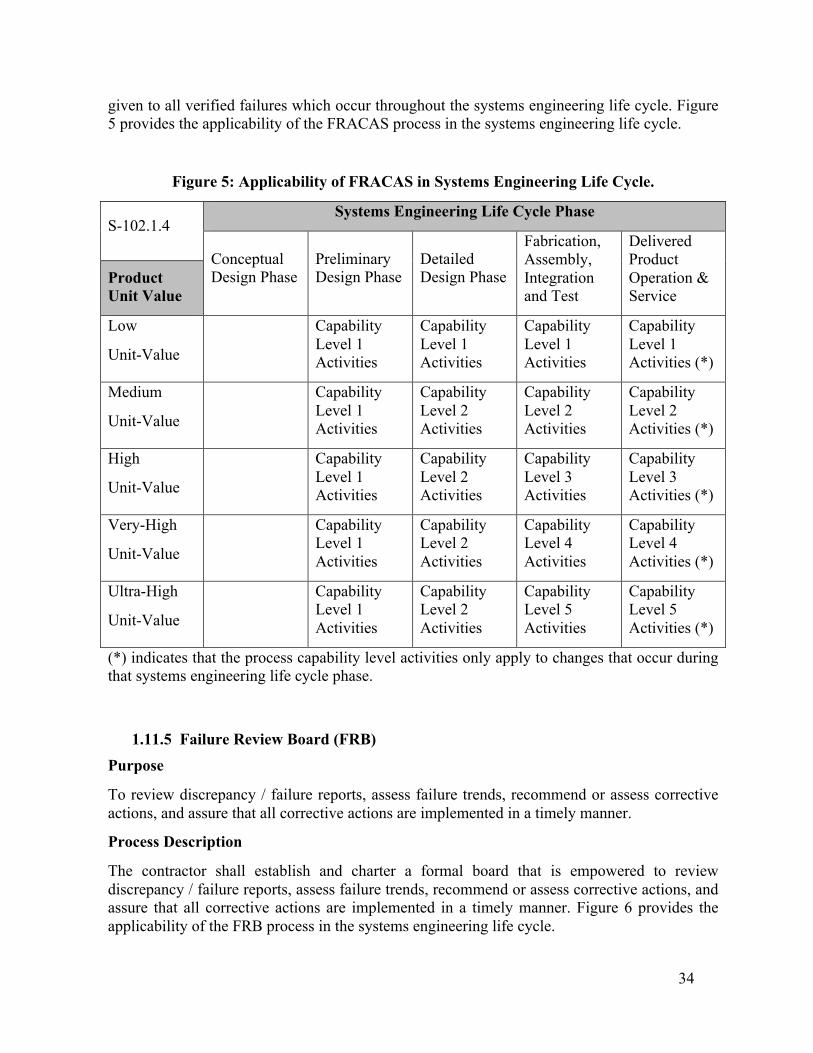
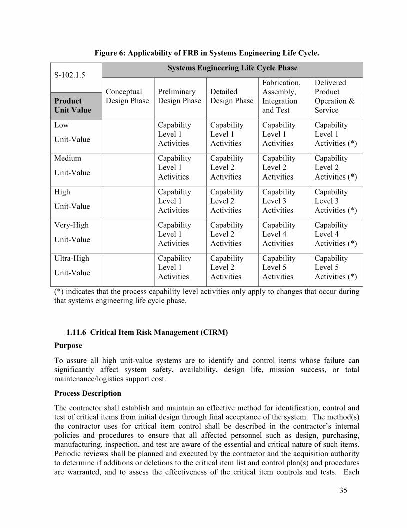
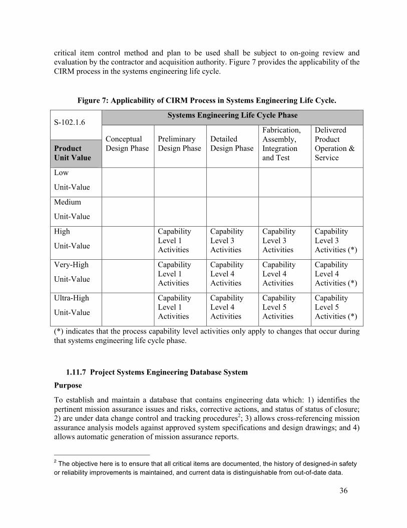
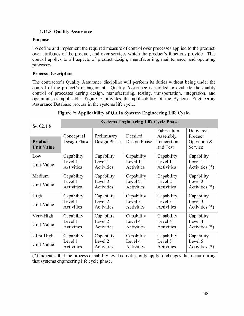
Figure 1: Generic Product Unit-Value/Criticality Categorization. ............................................... 29!Figure 2: Applicability of QAPP Process in Systems Engineering Life Cycle. ........................... 31!Figure 3: Applicability of Subcontractor and Supplier Mission Assurance Management Process in Systems Engineering Life Cycle............................................................................................... 32!Figure 4 : Applicability of QAWG in Systems Engineering Life Cycle. ..................................... 33!Figure 5: Applicability of FRACAS in Systems Engineering Life Cycle. ................................... 34!Figure 6: Applicability of FRB in Systems Engineering Life Cycle. ........................................... 35!Figure 7: Applicability of CIRM Process in Systems Engineering Life Cycle. ........................... 36!Figure 8 : Applicability of Project Mission Assurance Database System in Systems Engineering Life Cycle...................................................................................................................................... 37!Figure 9: Applicability of QA in Systems Engineering Life Cycle.............................................. 38!Figure 10: Applicability of CM in Systems Engineering Life Cycle. .......................................... 39!Figure 11: Applicability of Fishbone Analysis Process in Systems Engineering Life Cycle....... 40!
v
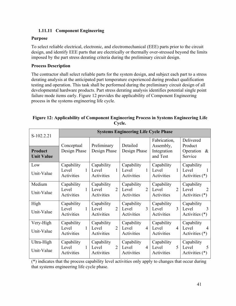
Figure 12: Applicability of Component Engineering Process in Systems Engineering Life Cycle........................................................................................................................................................ 41!Figure 13: Applicability of ESS Process in Systems Engineering Life Cycle. ............................ 42!Figure 14: Corrective Action Request (CAR) Form..................................................................... 60! TABLES
Table 1: Quality Assurance Responsibilities/Accountabilities....................................................... 3!Table 2: Minimum Qualifications for Set Quality Engineering Lead ............................................ 4!Table 3: Quality Assurance Program Objectives vs. Systems Engineering Artifacts Matrix. ..... 10!Table 4: Normalized 4-Point Quality Assurance Program Metrics. ............................................. 43!Table 5: Stream A and Stream B time domains derive from same classes................................... 47!
1
1. QUALITY POLICY AND ADMINISTRATION
1.1 Scope This document is the Quality Assurance Program Command Media. It is a dynamic document (i.e., a living document) that describes the company-wide quality assurance (QA) policies, processes, and management systems that are applied throughout the life cycle of all SET products and services. The requirements stated herein are grouped according to the unit-value/criticality of the SET product or service that they are applied to. These requirements and their enabling activities are purposely described in general terms, highlighting the key QA activities and associated artifacts. A detailed description of how the QA requirements and objectives of a particular SET project are met is found in the QA Program Plan of that project. Suggestions for improving this document should be brought to the attention of the SET President.
1.2 Purpose
The purpose of the SET QA Program is to identify the activities required to assure all product qualification requirements are met during design, manufacturing, and assembly. This document identifies the QA activities that should be done and describes how they should be done. The QA Program Plan (QAPP) is intended to be a living document that is updated as needed. Each project’s Lead QA Engineer is responsible for developing a QAPP that will achieve the project’s QA requirements and objectives in a cost-effective manner. Cumulatively, the tasks described in the QAPP form a structured quality system. However, the QAPP is not intended to stifle opportunities to adopt improvements in the quality system that is already in place. Long-term efforts to continuously improve product or process quality are documented in the SET Quality Improvement Plan.
1.3 Document Organization This command media is organized in eight sections:
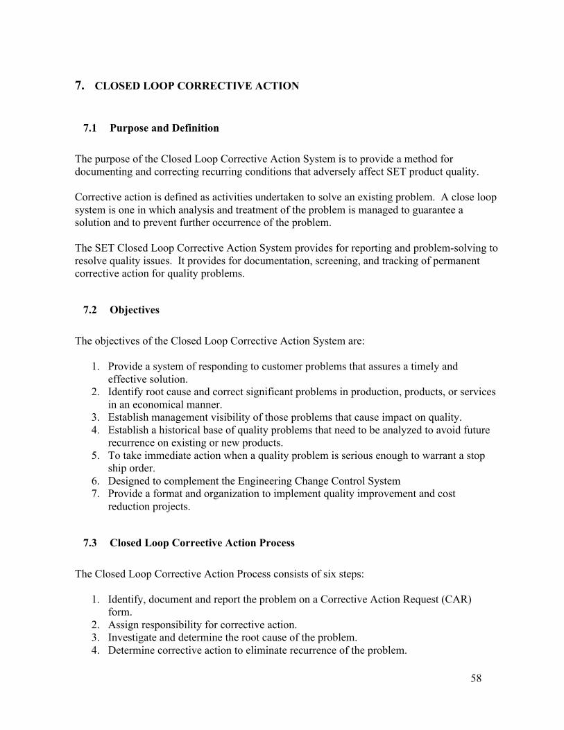
1. Quality Assurance Policy and Administration 2. Overview of SET Operations 3 Product Design Management 4 Supplier Quality Assurance 5 Production Quality Control 6 Customer Contact and Field Performance 7 Closed Loop Corrective Action 8 Employee Management, Training, etc
2
These eight sections represent the collective goals and objectives for quality assurance by our management team. They represent the essence of our past successful performance and our future expectations. While some changes are inevitable, we expect to continue to implement quality assurance in a cost-effective manner that is commensurate with the unit-value/criticality of the product that it is applied to.
1.4 SET Quality Assurance Policy
Our entire management team is committed to SET’s long-standing policy to deliver products and services that conform to their documented specifications at minimum cost. This policy fosters a company-wide philosophy of “high-quality at low-cost” among our managers, staff, and subcontractors. Each person and organization is responsible for establishing and maintaining high standard in their work, with emphasis on doing it right the first time. When required by a project, SET will allocate resources to establish a process to continuously improve our capability to prevent defects from occurring. This process will be implemented in accordance with a Quality Improvement Plan, which will be a living document that is updated on a regular basis. The primary focus of this plan is to improve root cause identification and corrective action implementation. The ancillary focus of this plan is to reduce costs. This dual-focus approach to QA planning facilitates SET maintaining its competitive edge in the space weather marketplace’s by providing cost-effective benefits to our customers over the long term.
1.5 Responsibilities /Accountabilities for Quality Assurance
The achievement of our corporate objectives depends on clearly defined responsibilities and accountabilities. In all aspects of SET’s business, the management team is responsible for defining and documenting specific responsibilities. The corporate hierarchy of responsibility is provided in Table 1.
Establish and meet corporate quality policies. Provide the resources and commitment to implement quality improvement opportunities identified by managers, staff, subcontractors, and customers.
Lead Quality Engineer
Define quality requirements and objectives. Maintain quality manuals and develop quality improvement plans for implementation by systems engineering functions. Develop quality measuring and reporting systems. See that goals are met and develop corrective action plans. Develop QA checklists and distribute them to quality assurance stake-holders. Provide QA training to QA stake-holders.
Project Managers
Meet QA requirements and objectives by actively managing the QA Program Plan tasks that fall within their area of responsibility. Establish quality goals for their area. Initiate action to correct unfavorable quality variances, assuring that the root cause of the variance is identified and eliminated. If required, provide resources to the personnel in their area to focus on quality improvement and cost reduction efforts that will provide customers with long term benefits. Establish personal expectations for high-quality work standards. Perform job responsibilities with a conscience effort to do the job right the first time. Initiate action to correct unfavorable quality variance. Accept full accountability for the quality of his or her work.
All Employees
If required, provide inputs to the management team for developing the Quality Improvement Plan. Be creative in identifying process improvement opportunities that will reduce costs and increase the level of quality.
1.6 Key Personnel Qualifications The key quality engineering personnel are required to meet certain minimum qualifications. Key quality engineering personnel are usually limited to the persons who have supervisory responsibility/technical approval authority for the quality assurance work. SET personnel assigned to QA responsibilities will be verified to have the appropriate qualifications (See Table 2) prior to performing quality assurance related duties. Theses qualifications include the appropriate education, training, demonstrated ability (through means such as certification and experience) to ensure they can satisfactorily fulfill their managerial roles and responsibilities. The Quality Engineering Lead will be trained how to select the appropriate quality assurance activities and tools commensurate with the product unit-value/criticality and the systems engineering life cycle. Figure 1 provides guidance for selecting the Criticality Level of various types of products.
4
Table 2: Minimum Qualifications for Set Quality Engineering Lead
Product Unit-Value / Criticality Level
Education Experience Training Certification
Crit. Level I or II BS in Engineering, Physical Science or other
Six years in quality assurance or related discipline
Quality Engineering Course & QA Mgmt Course or equivalent
Certified Quality Professional (CQP) or Professional Engr. or equivalent
Crit. Level III BS in Engineering, Physical Science or other
Four years in quality assurance or related discipline
Quality Engineering Course & QA Mgmt Course or equivalent
CQP or Professional Engr. or equivalent
Level IV Bachelor's Degree plus training in quality assurance
Two years in quality assurance or related discipline
Quality Engineering Course & QA Mgmt Course or equivalent
Cert. Engr. or Professional Engr. or equivalent
Crit. Level V High School Diploma plus training in quality assurance
Four years in quality assurance
Quality Engineering Course & QA Mgmt Course or equivalent
Cert. Technician or equivalent
1.7 Tools The Quality Engineering Lead is responsible for properly equipping the systems engineering personnel with the appropriate QA tools (e.g. Hazard Log Database) for implementing the planned quality assurance program tasks.
5
1.8 Systems Engineering Artifacts Systems engineering artifacts will be collected or developed, and maintained to document the quality assurance efforts of SET and its subcontractors. The artifacts listed below are of various types, and include the documents that SET is required to develop in accordance with the Statement of Work:
1. Contractor’s Internal QA Program Command Media. 2. Contractor’s proposal. 3. Customer’s Statement of Work. 4. Contractor’s subcontractor RFP/SOW 5. Military and Commercial Standards and Guides
a. MIL-STD-45662A b. MIL-STD-882C c. MIL-STD-1629A d. SMC Standard SMC-S-003T e. Volume set of AIAA S-102 Mission Assurance Standards f. TBS Decision Analysis Guide (Similar to Quality Function Deployment Method)
(Ref: SOW Section 3.12 DECISION ANALYSIS) 6. Work Breakdown Structure (WBS) 7. Systems Engineering Management Plan (SEMP) 8. Integrate Master Plan (IMP) 9. Integrated Master Schedule (IMS) 10. QA Program Budget Plan 11. QA Program Budget Report 12. Individual Systems Engineering Discipline Plans/Charters
a. Risk Management Plan (Ref: SOW Section 3.10 RISK/OPPORTUNITY MANAGEMENT)
b. System Safety Program Plan (SSPP) i. Capability-based System Safety Process Description
(a) Hazard Analysis (b) Product Safety Testing (c) Subcontractor/Supplier System Safety Program Management (Ref:
SOW Section 3.8 SUPPLIER MANAGEMEN) ii. System Safety Program Technical Performance Metrics (Ref: SOW
Section 3.10.1 Technical Performance Measurement) (a) System Safety Program Inspection/Audit Criteria
c. Reliability, Maintainability, Availability and Dependability (RMAD) Program Plan
i. Capability-based RMAD Process Description (a) Product FMECA (b) System Reliability Modeling (c) Component Reliability Predictions
a. Software Component Reliability Predictions (d) Maintainability Predictions
6
(e) Finite Element Analysis a. Circuit Structural Stress Analysis b. Circuit Thermal Stress Analysis
(f) Worst Case Analysis (g) Reliability Development/Growth Testing (h) Reliability Life Testing (i) Subcontract/Supplier RMAD Program Management (Ref: SOW
Section 3.8 SUPPLIER MANAGEMEN) ii. RMAD Program Technical Performance Metrics (Ref: SOW Section
3.10.1 Technical Performance Measurement) (a) RMAD Program Inspection/Audit Criteria
d. Quality Assurance Program Plan (QAPP) (Ref: SOW Section 3.9 QUALITY) i. Capability-based Quality Assurance Process Description
(a) Quality Assurance (b) Systems Engineering Database System
a. Hazard Report Log/Database b. FMECA Report Database c. Critical Item Report Database d. Failure/Discrepancy Report (FR/DR) Database e. Lessons Learned Database f. Risk Management Database
Section 3.8 SUPPLIER MANAGEMEN) ii. QA Program Technical Performance Metrics (Ref: SOW Section 3.10.1
Technical Performance Measurement) (a) QA Program Inspection/Audit Criteria
e. Quality Improvement Plan f. System Safety Working Group (SSWG) Charter g. Reliability and Maintainability Working Group (RMWG) Charter h. QA Working (QAWG) Group Charter i. Failure Review Board Charter j. Configuration Control Board (CCB) Charter k. Lessons Learned Approval Process Plan
7
l. Lessons Learned Review Committee (LLRC) Charter m. Requirements Verification Plan (RVP) (Ref: SOW Section 3.19
VERIFICATION) i. Software Requirements Verification Plan (RVP) (Ref: SOW Section 3.18
CODE & UNIT TEST) 13. Systems Engineering Discipline Management Reports
a. Lessons Learned Review Committee (LLRC) Meeting Minutes b. Lessons Learned Database Report c. Hazard Log/Database Report d. Failure/Discrepancy Report (FR/DR) e. Risk Submittal f. Risk Management Database Report g. System Safety Working Group (SSWG) Meeting Minutes Report h. System Safety Program Inspection/Audit Report i. Reliability and Maintainability Working Group (RMWG) Meeting Minutes
Report j. RMAD Program Inspection/Audit Report k. QA Working Group (QAWG) Meeting Minutes Report l. QA Program Inspection/Audit Report m. Production/Build Records n. Failure Review Board (FRB) Meeting Minutes Report o. Engineering Change Proposal (ECP) p. Configuration Control Board (CCB) Meeting Minutes Report q. Configuration Control Database Report r. Comment Resolution Matrix (CRM) s. Waiver Request t. Approved Waiver Report u. Shipment Records v. Training Materials
i. System Safety Training Materials ii. RMAD Training Materials
iii. QA Training Materials 14. Systems Engineering Discipline Engineering and Evaluation Reports
Section 3.16 SOFTWARE REQUIREMENTS ANALYSIS) ii. Preliminary Hazard Analysis
iii. Subsystem Hazard Analysis iv. System Hazard Analysis v. Operating and Support Hazard Analysis
vi. Health Hazard Assessment
8
c. System Architecture Design Trade Study Report (Ref: SOW Section 3.15 ARCHITECTURE DESIGN)
i. Software Architecture Design Trade Study Report (Ref: SOW Section 3.17 SOFTWARE DESIGN)
d. Failure Mode, Effects and Criticality Analysis (FMECA) Report e. Reliability Prediction Report f. Hazard Report g. Worst Case Analysis Report h. Defect Avoidance Checklists
i. Design Safety Checklist ii. Design Reliability Checklist
iii. QA Checklist i. Fishbone Analysis Report j. Failure Analysis Report k. Part Stress Derating Analysis Report l. Process FMECA Report m. Approved Parts List (APL) Report n. Preferred Parts List (PPL) Report o. Critical Items List (CIL) Report p. Statistical Process Control (SPC) Report q. Waiver Report
15. Systems Engineering Discipline Test Reports a. Environmental Stress Screening (ESS) Report b. Reliability Development/Growth Testing Report c. Reliability Life Testing Report
16. Product Specifications. Documents that contain detailed descriptions and drawings that specify the key requirements of each major item produced.
17. Calibration Standards. Documents that define the test equipment calibration requirements and the criteria for interpreting product outputs observed during testing.
18. Production/Build Procedures. Documents that identify the individual process steps for producing/building each product and or class of products.
a. Physical Layout Drawings b. Bill of Materials (BOM) c. Manufacturing Work Instructions d. Computer Program Logic Flow Diagrams e. Computer Program Source Code
19. Inspection Procedure. A document that covers procedures for inspecting individual products and or class of products.
20. End of Life Plan (EOLP)
1.9 Structure of SET Quality Assurance Program Many aspects of quality assurance are hard to define because the word quality has several meanings depending on usage. At SET, quality is defined as follows:
9
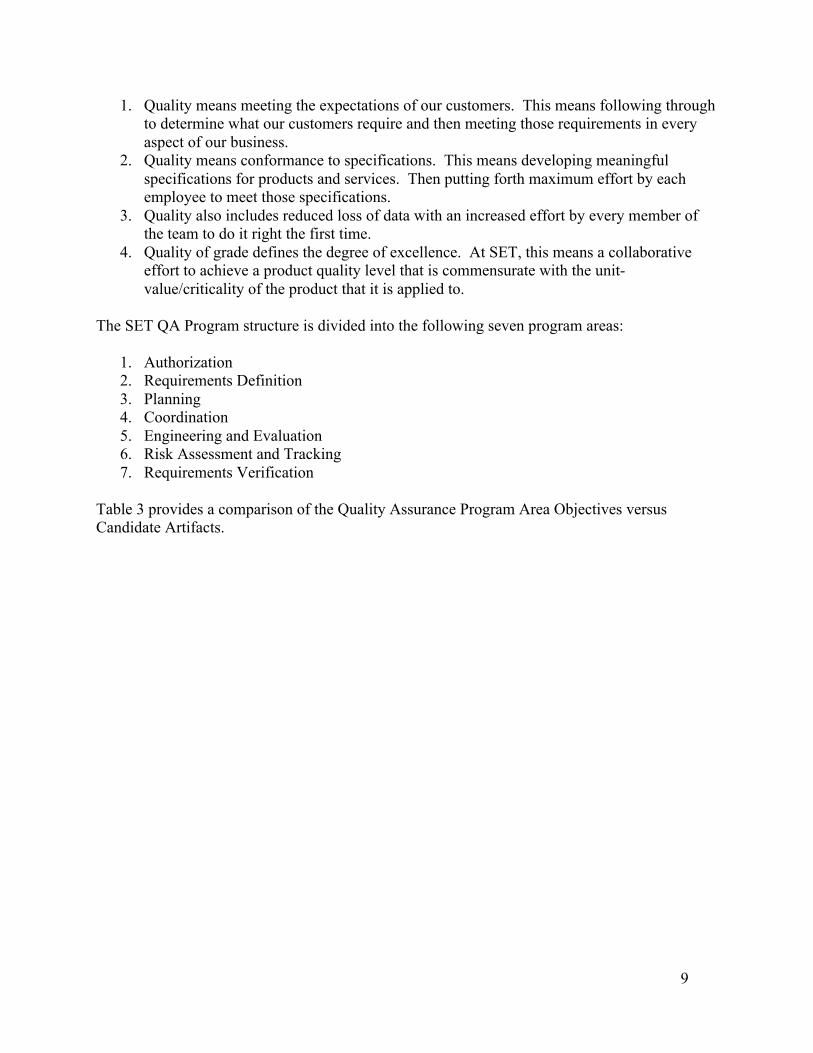
1. Quality means meeting the expectations of our customers. This means following through to determine what our customers require and then meeting those requirements in every aspect of our business.
2. Quality means conformance to specifications. This means developing meaningful specifications for products and services. Then putting forth maximum effort by each employee to meet those specifications.
3. Quality also includes reduced loss of data with an increased effort by every member of the team to do it right the first time.
4. Quality of grade defines the degree of excellence. At SET, this means a collaborative effort to achieve a product quality level that is commensurate with the unit-value/criticality of the product that it is applied to.
The SET QA Program structure is divided into the following seven program areas:
Table 3 provides a comparison of the Quality Assurance Program Area Objectives versus Candidate Artifacts.
10
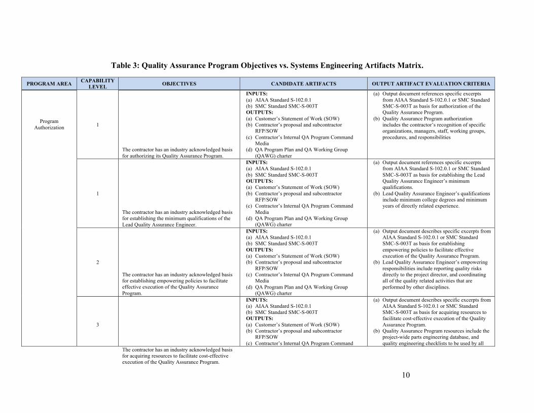
Table 3: Quality Assurance Program Objectives vs. Systems Engineering Artifacts Matrix.
PROGRAM AREA CAPABILITY LEVEL OBJECTIVES CANDIDATE ARTIFACTS OUTPUT ARTIFACT EVALUATION CRITERIA
1
The contractor has an industry acknowledged basis for authorizing its Quality Assurance Program.
INPUTS: (a) AIAA Standard S-102.0.1 (b) SMC Standard SMC-S-003T OUTPUTS: (a) Customer’s Statement of Work (SOW) (b) Contractor’s proposal and subcontractor
RFP/SOW (c) Contractor’s Internal QA Program Command
Media (d) QA Program Plan and QA Working Group
(QAWG) charter
(a) Output document references specific excerpts from AIAA Standard S-102.0.1 or SMC Standard SMC-S-003T as basis for authorization of the Quality Assurance Program.
(b) Quality Assurance Program authorization includes the contractor’s recognition of specific organizations, managers, staff, working groups, procedures, and responsibilities
1
The contractor has an industry acknowledged basis for establishing the minimum qualifications of the Lead Quality Assurance Engineer.
INPUTS: (a) AIAA Standard S-102.0.1 (b) SMC Standard SMC-S-003T OUTPUTS: (a) Customer’s Statement of Work (SOW) (b) Contractor’s proposal and subcontractor
RFP/SOW (c) Contractor’s Internal QA Program Command
Media (d) QA Program Plan and QA Working Group
(QAWG) charter
(a) Output document references specific excerpts from AIAA Standard S-102.0.1 or SMC Standard SMC-S-003T as basis for establishing the Lead Quality Assurance Engineer’s minimum qualifications.
(b) Lead Quality Assurance Engineer’s qualifications include minimum college degrees and minimum years of directly related experience.
2
The contractor has an industry acknowledged basis for establishing empowering policies to facilitate effective execution of the Quality Assurance Program.
INPUTS: (a) AIAA Standard S-102.0.1 (b) SMC Standard SMC-S-003T OUTPUTS: (a) Customer’s Statement of Work (SOW) (b) Contractor’s proposal and subcontractor
RFP/SOW (c) Contractor’s Internal QA Program Command
Media (d) QA Program Plan and QA Working Group
(QAWG) charter
(a) Output document describes specific excerpts from AIAA Standard S-102.0.1 or SMC Standard SMC-S-003T as basis for establishing empowering policies to facilitate effective execution of the Quality Assurance Program.
(b) Lead Quality Assurance Engineer’s empowering responsibilities include reporting quality risks directly to the project director, and coordinating all of the quality related activities that are performed by other disciplines.
Program Authorization
3
The contractor has an industry acknowledged basis for acquiring resources to facilitate cost-effective execution of the Quality Assurance Program.
INPUTS: (a) AIAA Standard S-102.0.1 (b) SMC Standard SMC-S-003T OUTPUTS: (a) Customer’s Statement of Work (SOW) (b) Contractor’s proposal and subcontractor
RFP/SOW (c) Contractor’s Internal QA Program Command
(a) Output document describes specific excerpts from AIAA Standard S-102.0.1 or SMC Standard SMC-S-003T as basis for acquiring resources to facilitate cost-effective execution of the Quality Assurance Program.
(b) Quality Assurance Program resources include the project-wide parts engineering database, and quality engineering checklists to be used by all
11
PROGRAM AREA CAPABILITY LEVEL OBJECTIVES CANDIDATE ARTIFACTS OUTPUT ARTIFACT EVALUATION CRITERIA
Media (d) QA Program Plan and QA Working Group
(QAWG) charter
QA stakeholders in the project.
4 & 5 The contractor has an industry acknowledged basis for interfacing with outside industry organizations and working groups whose charter/goal is to optimize the effectiveness of industry acknowledged quality assurance methods.
INPUT: (a) AIAA Standard S-102.0.1 OUTPUT: (a) Contractor’s Internal QA Program Command
Media
(a) Output document describes specific excerpts from AIAA Standard S-102.0.1 as basis for interfacing with outside industry organizations and working groups whose charter/goal is to maximize the effectiveness and minimize the risk of industry recognized quality engineering methods.
(b) The types of information to be exchanged with outside industry organizations include non-proprietary lessons learned, hazard reports, component reliability models, and open source computerized tool models.
1 All of the applicable systems engineering requirements (including quality and certification requirements) and self-imposed objectives are identified by the lead of each systems engineering discipline using System Requirements Analysis and Software Requirements Analysis methods.
INPUTS: (c) AIAA Standard S-102.0.1 (a) SMC Standard SMC-S-003T (b) Customer’s Statement of Work (SOW) (c) Contractor’s proposal and subcontractor
RFP/SOW (d) Contractor’s Internal QA Program Command
Media OUTPUT: (e) QA Program Plan and QA Working Group
(QAWG) charter
(a) All of the quality requirements and their sources are identified in the Requirements vs. Tasks Matrix in the QAPP.
(b) Each discipline is supposed to have a similar matrix in their respective Plan to identify the tasks that will be performed to achieve their particular systems engineering requirements.
1
All implemented systems engineering processes are required to be actively controlled.
INPUTS: (a) Customer’s Statement of Work (SOW) (b) Contractor’s proposal and subcontractor
RFP/SOW (c) Contractor’s Internal QA Program Command
Media (d) Systems Engineering Management Plan (e) Integrated Master Plan OUTPUT: (a) Work Breakdown Structure
(a) The contractor’s WBS establishes active control over all implemented systems engineering processes.
Requirements Definition
1
The applicable quality requirements (including quality certification requirements and specified configuration requirements) are incorporated in all program documents that impact product quality?
INPUTS: (a) AIAA Standard S-102.0.1 (b) SMC Standard SMC-S-003T (c) Customer’s Statement of Work (SOW) (d) Contractor’s proposal and subcontractor
RFP/SOW (e) Contractor’s Internal QA Program Command
(a) All of the quality requirements and their sources are identified in the Requirements vs. Tasks Matrix in the QAPP.
(b) QAPP includes a requirement versus responsible discipline matrix that identifies all of the QA requirements that other disciplines in Systems Engineering have. Each discipline is supposed to
12
PROGRAM AREA CAPABILITY LEVEL OBJECTIVES CANDIDATE ARTIFACTS OUTPUT ARTIFACT EVALUATION CRITERIA
Media OUTPUTS: (a) QA Program Plan and QA Working Group
(QAWG) charter (b) Individual Systems Engineering Discipline Plans (c) Product specifications
have a similar matrix in their respective Plan. These Plans are supposed to identify the tasks that will be performed to achieve the quality requirements.
1
All of the required deliverables are identified, along with the required reporting format for each one.
INPUTS: (a) AIAA Standard S-102.0.1 (b) SMC Standard SMC-S-003T (c) Customer’s Statement of Work (SOW) (d) Contractor’s proposal and subcontractor
RFP/SOW OUTPUTS: (a) QA Program Plan and QA Working Group
(QAWG) charter (b) Individual Systems Engineering Discipline Plans
(a) The customer’s Statement of Work (SOW) and the contractor’s subcontractor RFP/SOW identifies the required deliverables, along with their required reporting formats.
(b) The SOW may call out deliverables identified in AIAA Standard S-102.0.1 or SMC Standard SMC-S-003T.
(c) All of the quality requirements and their sources are identified in the Requirements vs. Tasks Matrix in the QAPP.
(d) QAPP includes a requirement versus responsible discipline matrix that identifies all of the QA requirements that other disciplines in Systems Engineering have. Each discipline is supposed to have a similar matrix in their respective Plan that identifies the tasks they will perform to achieve their quality requirements.
2
All applicable quality requirements are flowed down to internal stakeholder and subcontractors.
INPUTS: (a) AIAA Standard S-102.0.1 (b) SMC Standard SMC-S-003T (c) Customer’s Statement of Work (SOW) (d) Contractor’s proposal and subcontractor
RFP/SOW (e) Contractor’s Internal QA Program Command
Media OUTPUTS: (a) QA Program Plan and QA Working Group
(QAWG) charter (b) Individual Systems Engineering Discipline Plans (c) Subcontractor SOW (d) Subcontractor QAPP
(a) All of the internal QA stakeholders and subcontractors are identified in the QAPP, along with their flowed down QA requirements.
(b) The subcontractor SOW identifies the flowed down QA requirements.
(c) Each subcontractor’s QAPP identifies the tasks to achieve their flowed down QA requirements.
3
The use of industry acknowledged analytical methods is required of all systems engineering disciplines.
INPUTS: (a) AIAA Standard S-102.0.1 (b) SMC Standard SMC-S-003T (c) Contractor’s Internal QA Program Command
Media OUTPUTS: (a) Individual Systems Engineering Discipline Plans
(a) Contractor’s Internal QA Program Command Media requires all systems engineering disciplines to use industry acknowledged analytical methods.
(b) The QAPP and Systems Engineering Discipline Plans and Reports should identify their analytical methods and the references to industry
13
PROGRAM AREA CAPABILITY LEVEL OBJECTIVES CANDIDATE ARTIFACTS OUTPUT ARTIFACT EVALUATION CRITERIA
(b) Systems Engineering Discipline Engineering and Evaluation Reports
acknowledgements.
3 Overlooked, unnecessary, or incorrect quality requirements are identified by using Decision Analysis, Mission Analysis, and Requirements Hazard Analysis, or equivalent methods.
3 Approved waivers are provided for all unmet contract-specified functional performance requirements, and approved exceptions are provided for all unmet contractor-specified configuration requirements.
INPUTS: (a) SEMP (b) IMP (c) Systems Engineering Discipline Engineering and
(a) The requirement for an approved waiver to be provided for all unmet contract-specified functional performance requirements should be called out in the SEMP and the IMP.
(b) Collectively, the Systems Engineering Discipline Engineering and Evaluation Reports should identify all unmet requirements.
(c) Approved Waiver Reports document the contractors rational for not meeting a significant requirement.
4 & 5 Criteria and frequency for self-inspections, and subcontractor proposal evaluations and audits are established.
INPUTS: (a) AIAA Standard S-102.0.1 (b) SMC Standard SMC-S-003T OUTPUT: (a) Contractor’s Internal QA Program Command
Media
(c) AIAA Standard S-102.0.1and SMC Standard SMC-S-003T provides guidance for self-inspections.
(a) Contractor’s internal QA Program Command Media defines the criteria and frequency for self-inspections, subcontractor proposal evaluations, and subcontractor audits.
4 & 5
The identification of analytical assumptions is required of all systems engineering disciplines.
INPUTS: (a) AIAA Standard S-102.0.1 (b) Contractor’s Internal QA Program Command
Media OUTPUTS: (a) QA Program Plan and QA Working Group
(QAWG) charter (b) Individual Systems Engineering Discipline Plans
(a) Contractor’s Internal QA Program Command Media requires all systems engineering disciplines to identify their analytical assumptions
(b) Systems engineering disciplines should include in their respective plans the requirement to identify their analytical assumptions
4 & 5
Quality assurance defines the standardized formats for exchanging systems engineering data, including subcontract quality assurance data deliverables.
INPUT: (a) AIAA Standard S-102.0.1 OUTPUT: (a) Contractor’s Internal QA Program Command
Media
(a) AIAA Standard S-102.0.1and SMC Standard SMC-S-003T provides guidance for standardized formats used to exchange systems engineering data,.
(b) Contractor’s Internal QA Program Command Media defines the required formats for exchanging systems engineering data, including subcontract quality assurance data deliverables.
14
PROGRAM AREA CAPABILITY LEVEL OBJECTIVES CANDIDATE ARTIFACTS OUTPUT ARTIFACT EVALUATION CRITERIA
1
All applicable quality requirements and self-imposed objectives that QA must meet are identified in the Quality Assurance Program Plan (QAPP).
INPUTS: (a) AIAA Standard S-102.0.1 (b) SMC Standard SMC-S-003T (c) Customer’s Statement of Work (SOW) (d) Contractor’s proposal and subcontractor
RFP/SOW (e) Contractor’s Internal QA Program Command
Media OUTPUTS: (a) QA Program Plan and QA Working Group
(QAWG) charter (b) Individual Systems Engineering Discipline Plans
(a) QAPP includes a requirement versus task matrix that identifies all of the tasks that QA will perform to achieve their quality requirements.
(b) Each discipline is supposed to have a matrix in their respective Plan that identifies the tasks they will perform to achieve their quality requirements.
1
All applicable quality requirements (including quality certifications) and self-imposed objectives that other Systems Engineering disciplines must meet are identified in the respective plan of each responsible discipline and in the QAPP. (These plans would include the Systems Engineering Management Plan, the Integrate Master Plan, and the Risk Management Plan.)
INPUTS: (a) AIAA Standard S-102.0.1 (b) SMC Standard SMC-S-003T (c) Customer’s Statement of Work (SOW) (d) Contractor’s proposal and subcontractor
RFP/SOW (e) Contractor’s Internal QA Program Command
Media OUTPUTS: (a) QA Program Plan and QA Working Group
(QAWG) charter (b) Systems Engineering Management Plan (SEMP) (c) Integrate Master Plan (IMP) (d) Risk Management Plan (e) Quality Improvement Plan (f) System Safety Program Plan (g) RMAD Program Plan (h) End of Life Plan (EOLP)
(a) QAPP includes a requirement versus task matrix that identifies all of the tasks that QA will perform to achieve their quality requirements.
(b) QAPP also includes a requirement versus responsible discipline matrix that identifies all of the QA requirements that other disciplines in Systems Engineering have.
(c) Each discipline is supposed to have a similar matrix in their respective Plan to identify the tasks that they will be perform to achieve their quality requirements.
Planning (Including Test Plans)
2
The selection of the measureable and level-of-effort (LOE) quality assurance tasks are based on: (1) comprehensive coverage of the quality requirements and self-imposed objectives, (2) optimized balance among quality assurance costs, schedules, and risk factors, and (3) the applicable system life cycle phases.
INPUTS: (a) AIAA Standard S-102.0.1 (b) SMC Standard SMC-S-003T (c) Work Breakdown Structure (WBS) (d) Customer’s Statement of Work (SOW) (e) Contractor’s proposal and subcontractor
RFP/SOW (f) Contractor’s Internal QA Program Command
Media OUTPUTS: (a) QA Program Plan and QA Working Group
(a) The contractor’s internal QA Program Command Media should include a product unit-value/criticality versus QA Program capability level matrix.
(b) The contractor’s internal QA Program Command Media also should include a product life cycle versus QA Program capability level activities matrix.
(c) All QA activities that can be “notionally” scheduled should be included in the Integrated Master Schedule (IMS). The rest of the activities should be allocated a fixed number of hours (i.e., Level of Effort) based on “estimated/anticipated” project support needs.
15
PROGRAM AREA CAPABILITY LEVEL OBJECTIVES CANDIDATE ARTIFACTS OUTPUT ARTIFACT EVALUATION CRITERIA
(d) QA Program Budget Plan
2
All subcontractor key quality assurance data products/deliverables are identified in the QAPP.
INPUTS: (a) AIAA Standard S-102.0.1 (b) SMC Standard SMC-S-003T (c) Customer’s Statement of Work (SOW) (d) Contractor’s proposal and subcontractor
RFP/SOW (e) Contractor’s Internal QA Program Command
Media OUTPUTS: (a) QA Program Plan and QA Working Group
(a) The QAPP identifies the subcontractor‘s quality assurance data products/deliverables and their respective required delivery dates.
(b) The SEMP and IMP also identify the subcontractor‘s quality assurance data products/deliverables
(c) The IMS also identifies the respective required delivery dates.
2
All planned and LOE quality assurance tasks are adequately funded.
INPUTS: (a) Contractor’s Internal QA Program Command
Media (b) QA Program Plan and QA Working Group
(QAWG) charter (c) Individual Systems Engineering Discipline Plans OUTPUTS: (a) Integrated Master Schedule (IMS) (b) QA Program Budget Plan
(a) The QAPP identifies all scheduled and LOE quality assurance tasks.
(b) The hours for the scheduled tasks are identified in the IMS.
(c) The rationale for the fixed hours for each LOE task is documented in the QA Program Budget Plan.
(d) The QA Program Budget Plan shows adequate funding for all of the QA tasks.
3
The use of validated analytical methods is planned for all systems engineering disciplines.
INPUTS: (a) Military and Commercial Standards and Guides (b) Contractor’s Internal QA Program Command
Media OUTPUTS: (a) QA Program Plan and QA Working Group
(QAWG) charter (c) Individual Systems Engineering Discipline Plans
(c) Contractor’s Internal QA Program Command Media requires all systems engineering disciplines to use validated analytical methods
(d) Systems engineering disciplines should include in their respective plans the intent to use only validated analytical methods
(e) Systems engineering disciplines identify all key assumptions in their analytical reports.
3
Plans are developed for safe disposal of hazardous materials and of the system itself during the post operational mission.
INPUTS: (a) Customer’s Statement of Work (SOW) (b) Contractor’s proposal and subcontractor
RFP/SOW (c) Contractor’s Internal QA Program Command
Media OUTPUTS: (a) QA Program Plan and QA Working Group
(QAWG) charter (b) System Safety Program Plan (SSPP) and System
Safety Working Group (SSWG) charter (c) End of Life Plan (EOLP)
(a) The QAPP identifies the system’s post-mission end of life (EOL) requirements that impact quality assurance
(b) The QAPP also identifies system safety as the coordinator of the development of the End of Life Plan (EOLP)
(c) The EOLP should comply with its required format and address all of the EOL requirements
16
PROGRAM AREA CAPABILITY LEVEL OBJECTIVES CANDIDATE ARTIFACTS OUTPUT ARTIFACT EVALUATION CRITERIA
4 & 5
A plan is developed and implemented to improve quality of the operational system over time.
INPUTS: (a) Customer’s Statement of Work (SOW) (b) Contractor’s proposal and subcontractor
RFP/SOW (c) Contractor’s Internal QA Program Command
Media (d) QA Program Plan and QA Working Group
(QAWG) charter OUTPUTS: (a) Project Quality Improvement Plan (b) Integrated Master Schedule (IMS) (c) FRACAS Plan (d) FRB Charter
(a) The QAPP should identify the system’s safety, reliability, and quality assurance (SR&QA) improvement requirements.
(b) The QAPP also identifies the Project Quality Improvement Plan development and implementation tasks.
(c) The Project Quality Improvement Plan should comply with its required format and address all of the quality improvement requirements.
(d) The schedule for implementing the Project Quality Improvement Plan should be identified in the IMS.
(e) The FRACAS and the FRB play crucial in roles in identifying and mitigating inherent quality defects. Those roles should be defined in the FRACAS Plan and FRB Charter.
1 Quality assurance participates in all program meetings/reviews that are run by other disciplines that make decisions which impact product quality. (NOTE: This objective includes Failure Review Board (FRB) and Configuration Control Board (CCB) meetings)
INPUTS: (a) AIAA Standard S-102.0.1 (b) SMC Standard SMC-S-003T (c) Customer’s Statement of Work (SOW) (d) Contractor’s proposal and subcontractor
RFP/SOW (e) Contractor’s Internal QA Program Command
Media OUTPUTS: (a) QA Program Plan and QA Working Group
(QAWG) charter (b) Individual Systems Engineering Discipline Plans
(a) All of the quality requirements and their sources are identified in the Requirements vs. Tasks Matrix in the QAPP.
(b) QAPP includes a requirement versus responsible discipline matrix that identifies all of the QA requirements that other disciplines in Systems Engineering have. Each discipline is supposed to have a similar matrix in their respective Plan. The Plan is supposed to identify the tasks that will be performed to achieve the quality requirements, and the intent to invite QA to all meetings involving product quality.
1
Quality assurance coordinates the documentation and maintenance of the as-built configurations of all major components
INPUTS: (a) Contractor’s Internal QA Program Command
Media (b) QA Program Plan and QA Working Group
(QAWG) charter (c) System drawings and schematics OUTPUTS: (a) Configuration Control Board (CCB) Database
Report
(a) The QAPP describes the process for coordinating the documentation and maintenance of the as-built configurations of all major components.
(b) All of the versions of the system drawings and schematics are maintained in the Configuration Control Database.
Program Coordination
1
Quality assurance coordinates the systems engineering activities that must be performed to obtain the applicable product quality certifications.
INPUTS: (a) AIAA Standard S-102.0.1 (b) SMC Standard SMC-S-003T (c) Military and Commercial QA Standards (d) Customer’s Statement of Work (SOW) (e) Contractor’s proposal and subcontractor
RFP/SOW
(a) The QAPP identifies each quality certification requirement and all of the disciplines that participate in obtaining each one.
(b) The Lead Quality Engineer ensures the quality certification requirements are included in the Plan of each participating discipline.
(c) The Lead Quality Engineer periodically convenes
17
PROGRAM AREA CAPABILITY LEVEL OBJECTIVES CANDIDATE ARTIFACTS OUTPUT ARTIFACT EVALUATION CRITERIA
(f) Contractor’s Internal QA Program Command Media
(g) QA Program Plan and QA Working Group (QAWG) charter
OUTPUTS: (a) Individual Systems Engineering Discipline Plans (b) QA Working Group (QAWG) Meeting Minutes
QA Working Group (QAWG) meetings to ensure that a collaborative effort is implemented to obtain the required quality certifications.
2
The Lead Quality Engineer tracks the status of tasks and customer deliverables that are shared with other Systems Engineering disciplines.
INPUTS: (a) AIAA Standard S-102.0.1 (b) SMC Standard SMC-S-003T (c) Customer’s Statement of Work (SOW) (d) Contractor’s proposal and subcontractor
RFP/SOW (e) Contractor’s Internal QA Program Command
Media (f) QA Program Plan and QA Working Group
(QAWG) charter (g) Individual Systems Engineering Discipline Plans OUTPUTS: (a) QA Working Group (QAWG) Meeting Minutes
(a) All of the quality requirements and their sources are identified in the Requirements vs. Tasks Matrix in the QAPP.
(b) QAPP includes a requirement versus responsible discipline matrix that identifies all of the QA requirements that other disciplines in Systems Engineering have. Each discipline is supposed to have a similar matrix in their respective Plan.
(c) The Lead Quality Engineer periodically convenes QA Working Group (QAWG) meetings to ensure that a collaborative effort is implemented to complete tasks and customer deliverables that are shared with other disciplines.
2
Quality assurance inputs to key project documents are properly reviewed, coordinated, and approved.
INPUTS: (a) Contractor’s Internal QA Program Command
Media (b) QA Program Plan and QA Working Group
(QAWG) charter OUTPUTS: (a) Product Specifications (b) Calibration Standards (c) Production Procedures (d) Inspection Procedures
(a) All key project documents that require QA inputs are identified in the QAPP
(b) Each project document for which quality assurance provides a significant input is supposed to have an approval page with a signature line for the Lead Quality Engineer.
2 The Lead Quality Engineer monitors the QA activities of subcontractors during product design, manufacture, assembly, test, inspection, shipping, and operations.
INPUTS: (a) Contractor’s proposal and subcontractor
RFP/SOW (b) Contractor’s Internal QA Program Command
Media (c) QA Program Plan and QA Working Group
(QAWG) charter OUTPUTS: (a) QA Working Group (QAWG) Meeting Minutes
(a) All of the subcontractor quality requirements and their sources are identified in the QAPP.
(b) The Lead Quality Engineer periodically convenes QA Working Group (QAWG) meetings to ensure that subcontractors are properly implementing their required QA tasks.
2
Quality assurance coordinates the documentation and maintenance of the functional test history of all major components.
INPUTS: (a) Contractor’s Internal QA Program Command
Media (b) QA Program Plan and QA Working Group
(QAWG) charter
(a) The QAPP describes the process for coordinating the documentation and maintenance of the functional test history of all major components..
(b) The Test Records are entered and maintained in the project-wide Systems Engineering Database.
18
PROGRAM AREA CAPABILITY LEVEL OBJECTIVES CANDIDATE ARTIFACTS OUTPUT ARTIFACT EVALUATION CRITERIA
(c) Test Reports OUTPUTS: (a) Project-wide Systems Engineering Database
3
Quality assurance coordinates the documentation and maintenance of the complete build history of all major components
INPUTS: (a) Contractor’s Internal QA Program Command
Media (b) QA Program Plan and QA Working Group
(QAWG) charter (c) Production/Build Records OUTPUTS: (a) Configuration Control Board (CCB) Database
Report
(a) The QAPP describes the process for coordinating the documentation and maintenance of the as-built configurations of all major components.
(b) All of the Production/Build Records are entered and maintained in the Configuration Control Database.
3 All quality assurance stake-holders are identified and provided with applicable Defect Avoidance Checklists that enhance their defect avoidance activities.
INPUTS: (a) Contractor’s Internal QA Program Command
Media (b) QA Program Plan and QA Working Group
(QAWG) charter OUTPUTS: (a) Defect Avoidance Checklists
(a) The QAPP identifies all of the Systems Engineering disciplines that have quality assurance responsibilities.
(b) The QAPP identifies the development and distribution of QA checklists as tasks.
(c) The Lead QA Engineer coordinates the documentation, approval, and distribution of defect avoidance checklists.
3
The contractor establishes and maintains a program-wide Systems Engineering Database.
(QAWG) charter (e) Individual Systems Engineering Discipline
Plans OUTPUTS: (a) Systems Engineering Database
(a) The SEMP, IMP, and QAPP define the program-wide quality assurance database structure and data fields.
(b) The Systems Engineering Discipline Plans collectively identify the required data fields in the Systems Engineering Database
3 Quality assurance collects, reviews, and utilizes QA lessons learned, as applicable, and ensures that other disciplines also collect and utilize QA lessons learned to help identify existing and potential quality defects early. NOTE: These lessons learned include design, test, and operating guidelines.
INPUTS: (a) Contractor’s Internal QA Program Command
Media (b) QA Program Plan and QA Working Group
(QAWG) charter (c) Individual Systems Engineering Discipline
(a) The SEMP, IMP, and QAPP describe the program-wide Lessons Learned Database structure
(b) The Lessons Learned Database Report describes the contents of the Lessons Learned Database
(c) Quality assurance is the administrator of the program-wide Lessons Learned Database
3 Quality assurance evaluates all aspects of the Mission Assurance Program to identify and approve
INPUTS: (a) Contractor’s Internal QA Program Command
(a) The SEMP, IMP, and QAPP describe the program-wide Lessons Learned Database
19
PROGRAM AREA CAPABILITY LEVEL OBJECTIVES CANDIDATE ARTIFACTS OUTPUT ARTIFACT EVALUATION CRITERIA
new candidate quality assurance lessons learned, and ensures that other disciplines do the same. NOTE: This objective includes evaluating customer reported failures and in-house subcontractor Failure Reports .
Media (b) QA Program Plan and QA Working Group
(QAWG) charter (c) Individual Systems Engineering Discipline
structure (b) The QAPP and individual Systems Engineering
Discipline Plans call out lesson learned identification as a key task
(c) Quality assurance and the other systems engineering disciplines submit new lessons learned to the Lessons Learned Review Committee (LLRC) for approval
3
Quality assurance coordinates the documentation and maintenance of the complete rework history of all major components.
INPUTS: (a) Contractor’s Internal QA Program Command
Media (b) QA Program Plan and QA Working Group
(QAWG) charter (c) Production/Build Records OUTPUTS: (a) Configuration Control Board (CCB) Database
Report
(a) The QAPP describes the process for coordinating the documentation and maintenance of the rework history of all major components.
(b) All of the Rework Records are entered and maintained in the Configuration Control Database.
4 & 5
Quality assurance coordinates the documentation and maintenance of the complete storage history of all major components.
INPUTS: (a) Contractor’s Internal QA Program Command
Media (b) QA Program Plan and QA Working Group
(QAWG) charter OUTPUTS: (a) Shipment Records (b) Project-wide Systems Engineering Database
(a) The QAPP describes the process for coordinating the documentation and maintenance of the storage history of all major components.
(b) The Shipment Records documents the storage history of all major components.
(c) The Shipment Records are entered and maintained in the project-wide Systems Engineering Database.
4 & 5
Quality assurance coordinates the documentation and maintenance of the traceability of lower level parts and materials in all safety-critical and mission-critical components.
INPUTS: (a) Contractor’s Internal QA Program Command
Media (b) QA Program Plan and QA Working Group
(QAWG) charter (c) FMECA OUTPUTS: (a) Critical Items List (CIL) (b) Project-wide Systems Engineering Database
(a) The QAPP describes the process for coordinating the documentation and maintenance of the traceability history of lower level parts and materials in all safety-critical and mission-critical components
(b) The FMECA identifies the critical items (c) The Critical Items List (CIL) documents the
traceability history of lower level parts and materials in all safety-critical and mission-critical components
(d) The CIL is entered and maintained in the project-wide Systems Engineering Database
20
PROGRAM AREA CAPABILITY LEVEL OBJECTIVES CANDIDATE ARTIFACTS OUTPUT ARTIFACT EVALUATION CRITERIA
4 & 5
Quality assurance coordinates the documentation and maintenance of the complete test and inspection history of lower level parts and materials in all safety-critical and mission-critical components.
INPUTS: (a) Contractor’s Internal QA Program Command
Media (b) QA Program Plan and QA Working Group
(QAWG) charter (c) FMECA OUTPUTS: (a) Critical Items List (CIL) (b) Project-wide Systems Engineering Database
(a) The QAPP describes the process for coordinating the documentation and maintenance of the complete test and inspection history of lower level parts and materials in all safety-critical and mission-critical components
(b) The FMECA identifies the critical items (c) The Critical Items List (CIL) documents the
complete test and inspection history of lower level parts and materials in all safety-critical and mission-critical components.
(d) The complete test and inspection history of lower level parts and materials are entered and maintained in the project-wide Systems Engineering Database.
4 & 5
Quality assurance coordinates the documentation and maintenance of the physical and chemical analysis history of lower level materials in all safety-critical and mission-critical components.
INPUTS: (a) Contractor’s Internal QA Program Command
Media (b) QA Program Plan and QA Working Group
(QAWG) charter (c) FMECA OUTPUTS: (a) Critical Items List (CIL) (b) Project-wide Systems Engineering Database
(a) The QAPP describes the process for coordinating the documentation and maintenance of the physical and chemical analysis history of lower level parts and materials in all safety-critical and mission-critical components.
(b) The FMECA identifies the critical items (c) The Critical Items List (CIL) documents the
physical and chemical analysis history of lower level parts and materials in all safety-critical and mission-critical components.
(d) The physical and chemical analysis history of lower level materials is entered and maintained in the project-wide Systems Engineering Database.
4 & 5 Quality assurance ensures stake-holders are trained to properly utilize the Defect Avoidance Checklists and computer-aided tools that they are provided with.
INPUTS: (a) AIAA Standard S-102.0.1 (b) Contractor’s Internal QA Program Command
Media (c) QA Program Plan and QA Working Group
(QAWG) charter (d) Individual Systems Engineering Discipline Plans OUTPUTS: (a) QA Training Materials
(a) All of the quality assurance tasks are identified in the QAPP and in various Plans of Systems Engineering disciplines.
(b) The guidance for performing each quality assurance task should be provided in some type of QA Training Materials.
Engineering & Evaluation 1
Detailed and comprehensive (a) Statistical Process Control (SPC) Reports, (b) Failure/Discrepancy Reports (FRs/DRs), (c) Fishbone Analysis Reports, (d) Failure Analysis Reports, (e) Part Stress Derating Analysis Report, and the (f) Environmental Stress Screening (ESS) Report are reviewed by quality assurance.
(a) The CIL is developed from the FMECA and Hazard Analysis Reports.
(b) The CIL is documented, approved, maintained, and updated as needed.
2 Safety, Reliability, and Quality Assurance (SR&QA) identify, evaluate, and resolve all differences between (1) the build-to and as-built configurations of major components, and (2) the qualification test and acceptance test of major components.
(a) Safety, Reliability, and Quality Assurance (SR&QA) review ECP for major components to identify and evaluate possible differences between (1) their build-to and as-built configurations, and (2) their qualification test and acceptance test.
(b) Significant differences that affect the product’s form, fit, or function are documented as risk submittals
2 Product Failure Mode, Effects and Criticality Analysis (FMECA) and Reliability Predictions are performed for all major components, and these analyses correctly represent the product’s design and operation.
(a) FMECA and Reliability Prediction Report are based on accurate functional diagram models and product descriptions.
(b) FMECA includes identification of both safety-critical and mission-critical functions.
3
Quality assurance ensures industry acknowledged analytical methods are utilized by all systems engineering disciplines.
INPUTS: (a) AIAA Standard S-102.0.1 (b) Contractor’s Internal QA Program Command
Media (c) Individual Systems Engineering Discipline Plans OUTPUT: (a) Systems Engineering Discipline Analytical
Reports
(a) Contractor’s QA Program Command Media requires all systems engineering disciplines to use industry acknowledged analytical methods for high unit-value/criticality products.
(b) The analytical reports of the various systems engineering disciplines should include references to verify each analytical method is acknowledged by industry.
4 & 5
The input data and assumptions that are utilized in all key engineering and analytical methods are evaluated with regard to their maturity.
INPUTS: (a) AIAA Standard S-102.0.1 (b) Contractor’s Internal QA Program Command
Media (c) Individual Systems Engineering Discipline Plans OUTPUT: (a) Systems Engineering Discipline Analytical
Reports
(a) Contractor’s QA Program Command Media requires all systems engineering disciplines to evaluate the maturity of the input data and assumptions that are utilized in all key engineering and analytical methods for high unit-value/criticality products.
(b) The analytical reports of the various systems engineering disciplines should identify the
22
PROGRAM AREA CAPABILITY LEVEL OBJECTIVES CANDIDATE ARTIFACTS OUTPUT ARTIFACT EVALUATION CRITERIA
maturity of the input data and assumptions used for each analytical method.
(c) The analytical reports of the various systems engineering disciplines should also identify any uncertainties associated with the input data.
4 & 5
Quality assurance ensures that validated computer-aided mission assurance tools are acquired and integrated to the greatest extent practical to form a comprehensive mission assurance toolset.
INPUTS: (a) AIAA Standard S-102.0.1 (b) Contractor’s Internal QA Program Command
Media (c) Individual Systems Engineering Discipline Plans OUTPUT: (a) Systems Engineering Discipline Analytical
Reports
(a) Contractor’s QA Program Command Media requires that validated computer-aided mission assurance tools are acquired and integrated to the greatest extent practical to form a comprehensive mission assurance toolset for very-high unit-value/criticality products.
(b) The analytical reports of the various systems engineering disciplines should identify the validated computer-aided mission assurance tools that were used.
1
The defect risk mitigation/control order of precedence is defined and enforced across the systems engineering process.
Media OUTPUTS: (a) QA Program Plan and QA Working Group
(QAWG) charter (b) Risk Management Plan (RMP) (c) Failure Review Board (FRB) Charter (d) Configuration Control Board (CCB) Charter
(a) Contractor’s internal QA Program Command Media requires using the risk and problem mitigation order of precedence that is consistent with AIAA Standard S-102.0.1, MIL-STD-882D, AFI 91-202 AFSPC SUP1, and AFI 91-217.
(b) The contractor’s QAPP, Risk Management Plan (RMP), FRB charter, and CCB charter should all define a risk and problem mitigation order of precedence that is consistent with AIAA Standard S-102.0.1 and MIL-STD-882D.
1
All concerns that are identified by FMECA, Worst Case Analysis, Parts Stress Derating Analysis, Circuit Thermal Stress Analysis, and Circuit Structural Stress Analysis are tracked and resolved appropriately.
INPUTS: (a) QA Program Plan and QA Working Group
(QAWG) charter (b) Risk Management Plan (RMP) (c) Failure Review Board (FRB) Charter (d) Configuration Control Board (CCB) Charter (e) FMECA Report (f) Worst Case Analysis Report (g) Parts Stress Derating Analysis Report (h) Circuit Thermal Stress Analysis Report (i) Circuit Structural Stress Analysis Report OUTPUTS: (a) Risk Management Database Report (b) Hazard Report Log/Database Report
(a) The contractor’s QAPP, QAWG Charter, Risk Management Plan, and other Plans, should describe the process for tracking and resolving concerns that are identified in analytical reports.
(b) The contractor’s Risk Management Database Report and the Hazard Report Log/Database Report identify the concerns that are being tracked.
Risk Assessment & Tracking
1 All high and serious defect risks are identified, documented, and appropriately adjudicated.
INPUTS: (a) Contractor’s Internal QA Program Command
(a) The contractor’s internal QA Program Command Media includes a requirement to identify all high
23
PROGRAM AREA CAPABILITY LEVEL OBJECTIVES CANDIDATE ARTIFACTS OUTPUT ARTIFACT EVALUATION CRITERIA
Media (b) Individual Systems Engineering Discipline Plans (c) QA Program Plan and QA Working Group
(QAWG) charter (d) Risk Management Plan (RMP) (e) Failure Review Board (FRB) Charter (f) Configuration Control Board (CCB) Charter OUTPUTS: (a) Risk Management Database Report (b) Hazard Report Log/Database Report
and serious defect risks. (b) The contractor’s QAPP and Risk Management
Plan (RMP) also should include a requirement to identify all high and serious defect risks.
(c) The identified high and serious risks are identified in the Risk Management Database Report and the Hazard Report Log/Database Report.
1
The implementation of defect risk mitigations/controls that are chosen are all tracked to closure.
INPUTS: (a) QA Program Plan and QA Working Group
(QAWG) charter (b) Risk Management Plan (RMP) (c) Failure Review Board (FRB) Charter (d) Configuration Control Board (CCB) Charter OUTPUTS: (a) Risk Management Database Report (b) Hazard Report Log/Database Report
(a) The contractor’s QAPP defines the risk and problem mitigation order of precedence that is consistent with AIAA Standard S-102.0.and MIL-STD-882D.
(b) The contractor’s Risk Management Plan (RMP), FRB charter, and CCB charter also should define the risk and problem mitigation order of precedence that is consistent with AIAA Standard S-102.0.and MIL-STD-882D.
(c) The contractor’s Risk Management Database Report and the Hazard Report Log/Database Report identify the defect risk mitigations/controls that are being tracked.
2
The defect risk metrics that are selected fully comply with the system safety risk metrics and the reliability risk metrics, in that order of precedence.
INPUTS: (a) AIAA Standard S-102.0.1 (b) SMC Standard SMC-S-003T (c) Customer’s Statement of Work (SOW) (d) Contractor’s proposal and subcontractor
RFP/SOW (e) Contractor’s Internal QA Program Command
Media OUTPUTS: (a) QA Program Plan and QA Working Group
(QAWG) charter (b) System safety Program Plan (SSPP) (c) RMAD Program Plan (d) Risk Management Plan (RMP)
(a) The SOW, contractor’s QA Program Command Media, QAPP, SSPP, RMAD Program Plan, and Risk Management Plan all should define the defect risk metrics.
(b) The system safety risk metrics should take precedence over the reliability risk metrics if they are different.
3 The Lead Quality Engineer convenes quality assurance working group (QAWG) meetings with peers on a regular basis to identify and mitigate or control quality assurance risks/problems.
INPUT: (a) QA Program Plan and QA Working Group
(QAWG) charter OUTPUT: (a) QA Working Group Meeting Minutes
(a) The QAWG Charter should call for the Lead Quality Engineer to convene QAWG meetings with peers on a regular basis to mitigate or control quality assurance risks and correct problems.
(b) The QAWG meeting minutes should verify the authority to convene QAWG meetings was exercised.
24
PROGRAM AREA CAPABILITY LEVEL OBJECTIVES CANDIDATE ARTIFACTS OUTPUT ARTIFACT EVALUATION CRITERIA
3
The contractor reports high and serious risks to the appropriate approval authority.
INPUTS: (a) AIAA Standard S-102.0.1 (b) SMC Standard SMC-S-003T (c) Customer’s Statement of Work (SOW) (d) Contractor’s proposal and subcontractor
RFP/SOW (e) Contractor’s Internal QA Program Command
Media OUTPUTS: (a) QA Program Plan and QA Working Group
(QAWG) charter (b) Risk Management Plan (RMP) (c) Risk Management Database Report (d) Hazard Report Log/Database Report
(a) The SOW and contractor’s internal QA Program Command Media include requirements to report high and serious defect risks to the appropriate approval authority.
(b) The contractor’s QAPP and Risk Management Plan (RMP) also should include a requirement to report high and serious defect risks to the appropriate approval authority.
(c) The Risk Management Database Report and Hazard Report Log/Database Report identify the approval authority for each risk submittal.
3
Quality assurance ensures that each request for a requirement waiver involves a system deficiency that has an acceptable level of risk.
INPUTS: (a) AIAA Standard S-102.0.1 (b) SMC Standard SMC-S-003T (c) Customer’s Statement of Work (SOW) (d) Contractor’s Internal QA Program Command
Media (e) System Safety Program Plan (SSPP) (f) RMAD Program Plan (g) QA Program Plan and QA Working Group
(QAWG) charter (h) Risk Management Plan (i) Waiver Request OUTPUTS: (a) Risk Submittal
(a) The contractor’s internal QA Program Command Media includes a requirement to ensure that each requests for a requirement waiver involves a system deficiency that has an acceptable level of risk.
(b) The acceptable risk criteria are identified in the SSPP, RMAD Program Plan, QAPP, and Risk Management Plan.
(c) Quality assurance evaluates the Waiver Request and generates a Risk Submittal.
(d) The Risk Submittal identifies the residual risk associated with the Waiver Request for a system deficiency.
4 & 5
Quality assurance periodically inspects/audits various systems engineering disciplines to identify and mitigate latent process risks early.
INPUTS: (j) AIAA Standard S-102.0.1 (k) SMC Standard SMC-S-003T (l) Customer’s Statement of Work (SOW) (m) Contractor’s Internal QA Program Command
Media (n) QA Program Plan and QA Working Group
(QAWG) charter OUTPUTS: (a) QA Program Inspection/Audit Report
(a) The contractor’s internal QA Program Command Media includes a requirement to periodically audit various systems engineering disciplines.
(b) The QA inspection/audit criteria are identified in the QA Program Command Media.
(c) The SOW and QAPP may include requirements for the customer to periodically inspect/audit the contractor, or for the contractor to periodically inspect/audit the major subcontractors.
(d) The results of the inspection/audit are documented in the QA Program Inspection/Audit Report.
4 & 5
Overlooked, missing, or deficient quality engineering and testing tasks are identified, assessed for residual risk, and those found to be unacceptable are reported to the appropriate risk acceptance
INPUTS: (a) AIAA Standard S-102.0.1 (b) SMC Standard SMC-S-003T (c) Customer’s Statement of Work (SOW)
(a) AIAA Standard S-102.0.1, SMC Standard SMC-S-003T, the SOW, the subcontractor SOW, and the contractor’s internal QA Program Command Media aid in identifying the required tasks.
25
PROGRAM AREA CAPABILITY LEVEL OBJECTIVES CANDIDATE ARTIFACTS OUTPUT ARTIFACT EVALUATION CRITERIA
authority for adjudication. (d) Subcontractor SOW (e) Contractor’s Internal QA Program Command
Media (f) QA Program Plan and QA Working Group
(QAWG) charter (g) Risk Management Plan (RMP) OUTPUT: (a) Requirements Hazard Analysis Report
(b) The contractor’s internal QA Program Command Media also includes a requirement to identify overlooked, missing, or deficient quality engineering and testing tasks.
(c) The contractor’s QAPP and Risk Management Plan (RMP) should include requirements to identify overlooked, missing, or deficient quality engineering and testing tasks.
(d) The Requirements Hazard Analysis Report identifies overlooked, missing, or deficient quality engineering and testing tasks.
1
Routine test methods are used to verify all non-mission-critical HW, SW, and procedures comply with applicable military, federal, national, international, and industry quality standards and certifications.
INPUTS: (a) Product Specifications (b) QA Program Plan and QA Working Group
(QAWG) charter OUTPUTS: (a) QAWG Meeting Minutes (b) Test Plans (c) Test Reports
(a) The contractor’s QAPP should identify the routine test methods used to verify all non-mission-critical HW, SW, and procedures comply with applicable military, federal, national, international, and industry quality standards and certifications.
(b) The contractor’s QAWG coordinated with Test Engineering to ensure cost-effective test methods are selected and implemented.
(c) The Test Plans describe the routine test procedures.
(d) The Test Reports provide the results of the routine test procedures.
1
The contractor evaluates and dispositions the functional test discrepancies of all major components
(a) The contractor’s QAPP should describe the process for evaluating and dispositioning the functional test discrepancies of all major components.
(b) The Discrepancy Report describes the test discrepancy/failure.
(c) The Failure Analysis Report and FRB meeting minutes identify the failure root cause and corrective action.
Verification (Including Product
Safety Testing)
2
Special demonstration, test, inspection, analysis, and simulation methods are used to verify mission-critical HW, SW, and procedures comply with QA requirements and self-imposed objectives. This objective partially fulfills Safety Verification. (MIL-STD-882C, Task 401)
INPUTS: (a) Product Specifications (b) Critical Items List (CIL) Report (c) QA Program Plan and QA Working Group
(QAWG) charter OUTPUTS: (a) Test Plans (b) Test Reports (c) QAWG Meeting Minutes Report
(a) The CIL should identify the special demonstrations, tests, inspections, analyses, simulations, and inspections used to verify mission-critical HW, SW, and procedures comply with QA requirements and self-imposed objectives.
(b) The QAWG coordinated with Test Engineering to ensure cost-effective test methods are selected and completed.
(c) The Test Plans describe the special test procedures.
26
PROGRAM AREA CAPABILITY LEVEL OBJECTIVES CANDIDATE ARTIFACTS OUTPUT ARTIFACT EVALUATION CRITERIA
(d) The Test Reports provide the results of the special test procedures.
3
The contractor performs a power-off test and a physical inspection on all major components, and documents the results.
INPUTS: (a) Product Specifications (b) Critical Items List (CIL) Report (c) QA Program Plan and QA Working Group
(QAWG) charter OUTPUTS: (a) Test Plans (b) Test Reports (c) QAWG Meeting Minutes Report
(a) The contractor’s QAPP should describe the power-off test and physical inspection that are to be performed on all major components.
(b) The QAWG coordinated with Test Engineering to ensure cost-effective test methods are selected and completed.
(c) The Test Plans describe the power-off test and physical inspection procedures.
(d) The Test Reports provide the results of the power-off test and physical inspection procedures.
3 Special demonstration, test, inspection, analysis, and simulation methods are used to verify safety-critical HW, SW, and procedures comply with QA requirements and self-imposed objectives. This objective partially fulfills Safety Verification. (MIL-STD-882C, Task 401)
INPUTS: (a) Product Specifications (b) Critical Items List (CIL) Report (c) QA Program Plan and QA Working Group
(QAWG) charter OUTPUTS: (a) Test Plans (b) Test Reports (c) QAWG Meeting Minutes Report
(a) The CIL should identify special demonstrations, tests, inspections, analyses, simulations, and inspections used to verify safety-critical HW, SW, and procedures comply with QA requirements and self-imposed objectives.
(b) The QAWG coordinated with Test Engineering to ensure cost-effective test methods are selected and completed.
(c) The Test Plans identify the special test procedures.
(d) The Test Reports provide the results of the special test procedures.
3
Quality assurance verifies that industry acknowledged methods were use by systems engineering discipline to perform their QA related tasks.
INPUTS: (a) QA Program Plan and QA Working Group
(QAWG) charter OUTPUTS: (a) Requirements Verification Planning (RVP)
Report (c) Project-wide Systems Engineering Database
(a) All of the quality requirements and their sources are identified in the Requirements vs. Tasks Matrix in the QAPP.
(b) QAPP includes a requirement versus responsible discipline matrix that identifies all QA related tasks performed by other disciplines in systems engineering. Each discipline is supposed to have a similar matrix in their respective Plan. These Plans are supposed to identify the tasks that will be performed to achieve the quality requirements.
(c) Quality assurance verifies that each system specification requirement has a corresponding RVP.
(d) The contractor’s QAPP should identify the quality related Requirements Verification Plans
27
PROGRAM AREA CAPABILITY LEVEL OBJECTIVES CANDIDATE ARTIFACTS OUTPUT ARTIFACT EVALUATION CRITERIA
(RVPs) and Requirements Verification Reports (RVRs) developed by other disciplines.
(e) The RVPs and RVRs are entered and maintained in the project-wide Systems Engineering Database.
4 & 5
The functional test data is subjected to Statistic Failure Trending Analysis.
INPUTS: (a) AIAA Standard S-102.0.1 (b) SMC Standard SMC-S-003T (c) QA Program Plan and QA Working Group
(QAWG) charter (d) Critical Items List (CIL) Report (e) Test Plans (f) Test Reports (g) Test Discrepancy Reports OUTPUTS: (a) Test Failure Analysis (b) Failure Review Board (FRB) Meeting Minutes
Report (c) Statistical Process Control (SPC) Analysis Report
(a) The contractor’s QAPP should describe the Statistic Failure Trending Analysis method that is performed on functional test data.
(b) The QAWG coordinated with Test Engineering to ensure appropriate data is collected to perform Statistic Failure Trending Analysis.
(c) The Test Plans identify the desired test metrics. (d) The Test Reports provide the test data used for
trending. (e) Test Discrepancy Reports describe the test failure
modes. (f) The Test Failure Analysis Reports identify the
root causes of failure. (g) The FRB meeting minutes identify the corrective
actions. (h) The Statistical Process Control (SPC) Analysis
identifies failure trends
4 & 5
Each incident of a functional or physical discrepancy of a lower level part or material in a mission-critical or safety-critical component is evaluated thoroughly.
(a) The contractor’s QAPP should describe the process for evaluating and dispositioning the functional or physical discrepancy of a lower level part or material in a mission-critical or safety-critical component.
(b) The Discrepancy Report describes the test discrepancy/failure.
(c) The Failure Analysis Report and FRB meeting minutes identify the failure root cause and corrective action.
28
1.10 Activity Selection for the Quality Assurance Program
The selection of activities for a particular QA Program is based on the required Capability Level. The contractor will use the product unit-value/criticality categorizations1 defined in Figure 1 as guidance, or provide rationale for placing a particular class of product in a different unit-value/criticality category. For a Capability Level 1 QA Program, the contractor’s QA Program planning effort will consist of selecting and scheduling the applicable enterprise-approved QA practices that are commensurate with the unit-value/criticality and life cycle phase of the product. If a Capability Level 2 or higher QA Program is required, the contractor will document, approve, and flow down, as appropriate, an official Quality Assurance Program Plan (QAPP) that is an integral part of the Systems Engineering Management Plan (SEMP). The contractor will establish a formal QAPP approval process, which includes acquisition activity review and concurrence. The QAPP will identify the quality assurance requirements and the pertinent guidance documents used to select the quality assurance activities. If a Capability Level 3 or higher QA Program is required, the contractor‘s QAPP will identify all key inputs and outputs of each scheduled QA activity. In all cases, quality assurance activities will be implemented in a holistic manner that minimizes duplication in effort and maximizes the timely exchange of systems engineering data. The contractor will consider the applicability of capability-level growth over the course of the product life cycle when planning the QA Program. The QAPP will be updated on an as required or as needed basis. As required updates will include contractually required delivery frequency and as needed updates will include collecting better input data.
1 The ordering of generic products according to five unit-value tiers was based on the collective engineering judgment of the S-102 Mission Assurance Working Group.
High Unit-Value / Criticality Products (Crit. III)
• Science satellites
• Cargo ships
• Mobil / mechanized weapons
• Freight trains
• Amusement park rides
• Elevators / escalators
• Small private aircraft / helicopters
• Automobiles / trucks / motorcycles
• Mission-critical hardware / software components
• Construction / demolition / excavation equipment
• Satellite communications relay stations
Medium Unit-Value / Criticality Products (Crit. IV)
• Industrial electronics
• Personal computers / peripherals
• Industrial computers / peripherals
• Farm equip
• Medical / laboratory equip
• Factory machinery
• Handheld construction / demolition / excavation equip
• Communications / utility equip
• Explosive devices
• Test / monitoring hardware/software components
• Computer operating system software
• Prototype systems / components
Low Unit-Value / Criticality Products (Crit. V)
• Motorized /
manual hand tools
• Fire arms
• Consumer electronics
• Household appliances
• Batteries
• Battery operated toys
• Infant/ children toys
• Computer application program software
30
1.11 Quality Assurance Program in the Systems Engineering Life Cycle
1.11.1 Quality Assurance Program Planning Purpose
Define processes which are: 1) implemented to achieve product and process quality assurance requirements, and 2) used to identify and mitigate or control product defects in a timely manner.
Process Description
The contractor will develop a Quality Assurance Program Plan (QAPP) that is capable of being cost-effectively implemented in accordance with the applicable system requirements and this Command Media. The QAPP will identify the resources, tools, skills, and training necessary to implement each QA activity. The contractor will distribute the initial draft through final release versions of the QAPP to all major stakeholders for review. The timing of the QAPP will allow the quality assurance stakeholder across systems engineering sufficient time to complete their tasks in a timely manner. The QAPP will define the objectives and approach for identifying, evaluating, and mitigating or controlling existing and potential deficiencies which pose a threat to system safety or mission success, throughout the product’s useful life. This process is implemented as part of the initial planning for all product development projects. The QAPP will describe how each QA activity is implemented, the roles of key participants, and the uses of key outputs. Figure 2 provides the notional applicability of the QAPP process in the systems engineering life cycle.
31
Figure 2: Applicability of QAPP Process in Systems Engineering Life Cycle.
Systems Engineering Life Cycle Phase S-102.1.1
Product Unit Value
Conceptual Design Phase
Preliminary Design Phase
Detailed Design Phase
Fabrication, Assembly, Integration and Test
Delivered Product Operation & Service
Low
Unit-Value
Capability Level 1 Activities
Capability Level 1 Activities
Capability Level 1 Activities
Capability Level 1 Activities
Capability Level 1 Activities (*)
Medium
Unit-Value
Capability Level 1 Activities
Capability Level 2 Activities
Capability Level 2 Activities
Capability Level 2 Activities
Capability Level 2 Activities (*)
High
Unit-Value
Capability Level 1 Activities
Capability Level 2 Activities
Capability Level 3 Activities
Capability Level 3 Activities
Capability Level 3 Activities (*)
Very-High
Unit-Value
Capability Level 1 Activities
Capability Level 2 Activities
Capability Level 4 Activities
Capability Level 4 Activities
Capability Level 4 Activities (*)
Ultra-High
Unit-Value
Capability Level 1 Activities
Capability Level 2 Activities
Capability Level 4 Activities
Capability Level 5 Activities
Capability Level 5 Activities (*)
(*) indicates that the process capability level activities only apply to changes that occur during that Systems Engineering life cycle phase.
1.11.2 Subcontractor and Supplier Mission Assurance Management Purpose
To define and oversee subcontractor and supplier processes which are: 1) implemented to achieve product and process mission assurance requirements; and 2) the means by which product and process deficiencies are identified and mitigated or controlled in a timely manner.
Process Description
Subcontractor and supplier mission assurance processes shall be monitored and controlled to assure: 1) their internal processes are consistent with those defined in their customer’s MAPP(s); 2) they verify compliance with all flowed down mission assurance requirements, or allow their customer to conduct on-site surveillance; 4) they exchange pertinent lessons learned with their customer; 5) they accept direction from their customer to improve their mission assurance capabilities, if needed. Subcontractor and supplier mission assurance products, such as, data and reports, shall be clearly identified in binding agreements with their customer.
32
Figure 3 provides the applicability of the Subcontractor and Supplier Mission Assurance Management process in the systems engineering life cycle.
Figure 3: Applicability of Subcontractor and Supplier Mission Assurance Management Process in Systems Engineering Life Cycle.
Systems Engineering Life Cycle Phase S-102.1.2
Product Unit Value
Conceptual Design Phase
Preliminary Design Phase
Detailed Design Phase
Fabrication, Assembly, Integration and Test
Delivered Product Operation & Service
Low
Unit-Value
Capability Level 1 Activities
Capability Level 1 Activities
Capability Level 1 Activities
Capability Level 1 Activities (*)
Medium
Unit-Value
Capability Level 1 Activities
Capability Level 2 Activities
Capability Level 2 Activities
Capability Level 2 Activities (*)
High
Unit-Value
Capability Level 1 Activities
Capability Level 3 Activities
Capability Level 3 Activities
Capability Level 3 Activities (*)
Very-High
Unit-Value
Capability Level 1 Activities
Capability Level 4 Activities
Capability Level 4 Activities
Capability Level 4 Activities (*)
Ultra-High
Unit-Value
Capability Level 1 Activities
Capability Level 4 Activities
Capability Level 5 Activities
Capability Level 5 Activities (*)
(*) indicates that the process capability level activities only apply to changes that occur during that systems engineering life cycle phase.
1.11.3 Quality Assurance Working Group (QAWG) Purpose
To conduct a formal or informal technical meeting to: 1) review a product or process that is characterized as potentially having a system safety or mission success issue / risk, and 2) collaborate as a group to identify unacceptable issues / risks and the actions necessary to close them appropriately.
Process Description
A group of engineers that are cognizant of the project’s quality assurance requirements shall periodically or spontaneously meet to review products and processes which are characterized as potentially having system safety or mission success issues / risks. This working group shall
33
identify unacceptable and credible issues / risks, and assure appropriate follow-up or corrective actions are taken to properly close them, with regard to timeliness, verification, and traceability. Figure 4 provides the applicability of the QAWG in the systems engineering life cycle.
Figure 4 : Applicability of QAWG in Systems Engineering Life Cycle.
Systems Engineering Life Cycle Phase S-102.1.3
Product Unit Value
Conceptual Design Phase
Preliminary Design Phase
Detailed Design Phase
Fabrication, Assembly, Integration and Test
Delivered Product Operation & Service
Low
Unit-Value
Medium
Unit-Value
High
Unit-Value
Capability Level 1 Activities
Capability Level 2 Activities
Capability Level 3 Activities
Capability Level 3 Activities
Capability Level 3 Activities (*)
Very-High
Unit-Value
Capability Level 1 Activities
Capability Level 2 Activities
Capability Level 4 Activities
Capability Level 4 Activities
Capability Level 4 Activities (*)
Ultra-High
Unit-Value
Capability Level 1 Activities
Capability Level 2 Activities
Capability Level 4 Activities
Capability Level 5 Activities
Capability Level 5 Activities (*)
(*) indicates that the process capability level activities only apply to changes that occur during that systems engineering life cycle phase.
1.11.4 Failure Reporting, Analysis and Corrective Action System (FRACAS) Purpose
To establish and implement a closed-loop system for recording and analyzing anomalies, determining the appropriate correction action, tracking actions to closure, and reporting on anomaly occurrence status.
Process Description
The contractor shall establish a FRACAS process to: 1) report, verify, analyze, and correct hardware and software anomalies; 2) monitor closure status of all verified anomalies to assure corrective actions are implemented in a timely manner; 3) provide anomaly data and reports to engineering functions (e.g., test discrepancy / failure reports); and 4) assure proper attention is
34
given to all verified failures which occur throughout the systems engineering life cycle. Figure 5 provides the applicability of the FRACAS process in the systems engineering life cycle.
Figure 5: Applicability of FRACAS in Systems Engineering Life Cycle.
Systems Engineering Life Cycle Phase S-102.1.4
Product Unit Value
Conceptual Design Phase
Preliminary Design Phase
Detailed Design Phase
Fabrication, Assembly, Integration and Test
Delivered Product Operation & Service
Low
Unit-Value
Capability Level 1 Activities
Capability Level 1 Activities
Capability Level 1 Activities
Capability Level 1 Activities (*)
Medium
Unit-Value
Capability Level 1 Activities
Capability Level 2 Activities
Capability Level 2 Activities
Capability Level 2 Activities (*)
High
Unit-Value
Capability Level 1 Activities
Capability Level 2 Activities
Capability Level 3 Activities
Capability Level 3 Activities (*)
Very-High
Unit-Value
Capability Level 1 Activities
Capability Level 2 Activities
Capability Level 4 Activities
Capability Level 4 Activities (*)
Ultra-High
Unit-Value
Capability Level 1 Activities
Capability Level 2 Activities
Capability Level 5 Activities
Capability Level 5 Activities (*)
(*) indicates that the process capability level activities only apply to changes that occur during that systems engineering life cycle phase.
1.11.5 Failure Review Board (FRB) Purpose
To review discrepancy / failure reports, assess failure trends, recommend or assess corrective actions, and assure that all corrective actions are implemented in a timely manner.
Process Description
The contractor shall establish and charter a formal board that is empowered to review discrepancy / failure reports, assess failure trends, recommend or assess corrective actions, and assure that all corrective actions are implemented in a timely manner. Figure 6 provides the applicability of the FRB process in the systems engineering life cycle.
35
Figure 6: Applicability of FRB in Systems Engineering Life Cycle.
Systems Engineering Life Cycle Phase S-102.1.5
Product Unit Value
Conceptual Design Phase
Preliminary Design Phase
Detailed Design Phase
Fabrication, Assembly, Integration and Test
Delivered Product Operation & Service
Low
Unit-Value
Capability Level 1 Activities
Capability Level 1 Activities
Capability Level 1 Activities
Capability Level 1 Activities (*)
Medium
Unit-Value
Capability Level 1 Activities
Capability Level 2 Activities
Capability Level 2 Activities
Capability Level 2 Activities (*)
High
Unit-Value
Capability Level 1 Activities
Capability Level 2 Activities
Capability Level 3 Activities
Capability Level 3 Activities (*)
Very-High
Unit-Value
Capability Level 1 Activities
Capability Level 2 Activities
Capability Level 4 Activities
Capability Level 4 Activities (*)
Ultra-High
Unit-Value
Capability Level 1 Activities
Capability Level 2 Activities
Capability Level 5 Activities
Capability Level 5 Activities (*)
(*) indicates that the process capability level activities only apply to changes that occur during that systems engineering life cycle phase.
To assure all high unit-value systems are to identify and control items whose failure can significantly affect system safety, availability, design life, mission success, or total maintenance/logistics support cost.
Process Description
The contractor shall establish and maintain an effective method for identification, control and test of critical items from initial design through final acceptance of the system. The method(s) the contractor uses for critical item control shall be described in the contractor’s internal policies and procedures to ensure that all affected personnel such as design, purchasing, manufacturing, inspection, and test are aware of the essential and critical nature of such items. Periodic reviews shall be planned and executed by the contractor and the acquisition authority to determine if additions or deletions to the critical item list and control plan(s) and procedures are warranted, and to assess the effectiveness of the critical item controls and tests. Each
36
critical item control method and plan to be used shall be subject to on-going review and evaluation by the contractor and acquisition authority. Figure 7 provides the applicability of the CIRM process in the systems engineering life cycle.
Figure 7: Applicability of CIRM Process in Systems Engineering Life Cycle.
Systems Engineering Life Cycle Phase S-102.1.6
Product Unit Value
Conceptual Design Phase
Preliminary Design Phase
Detailed Design Phase
Fabrication, Assembly, Integration and Test
Delivered Product Operation & Service
Low
Unit-Value
Medium
Unit-Value
High
Unit-Value
Capability Level 1 Activities
Capability Level 3 Activities
Capability Level 3 Activities
Capability Level 3 Activities (*)
Very-High
Unit-Value
Capability Level 1 Activities
Capability Level 4 Activities
Capability Level 4 Activities
Capability Level 4 Activities (*)
Ultra-High
Unit-Value
Capability Level 1 Activities
Capability Level 4 Activities
Capability Level 5 Activities
Capability Level 5 Activities (*)
(*) indicates that the process capability level activities only apply to changes that occur during that systems engineering life cycle phase.
1.11.7 Project Systems Engineering Database System Purpose
To establish and maintain a database that contains engineering data which: 1) identifies the pertinent mission assurance issues and risks, corrective actions, and status of status of closure; 2) are under data change control and tracking procedures2; 3) allows cross-referencing mission assurance analysis models against approved system specifications and design drawings; and 4) allows automatic generation of mission assurance reports.
2 The objective here is to ensure that all critical items are documented, the history of designed-in safety or reliability improvements is maintained, and current data is distinguishable from out-of-date data.
37
Process Description
The contractor shall establish and maintain a project database that: (1) identifies the pertinent mission assurance issues and risks, corrective actions, and status of closure; 2) is under data change control and tracking procedures; 3) allows cross-referencing mission assurance analysis models against approved system specifications and design drawings; 4) allows automatic generation of mission assurance reports; 5) for Capability 3 and above mission assurance programs, allows an authorized person to indicate particular data is a lessons learned candidate; and 6) for Capability 4 and above mission assurance programs, contains data records referenced to one or more keyword data element descriptions (DED) listed in Annex C. Figure 8 provides the applicability of the Project Mission Assurance Database System process in the systems engineering life cycle.
Figure 8 : Applicability of Project Mission Assurance Database System in Systems Engineering Life Cycle.
Systems Engineering Life Cycle Phase S-102.1.7
Product Unit Value
Conceptual Design Phase
Preliminary Design Phase
Detailed Design Phase
Fabrication, Assembly, Integration and Test
Delivered Product Operation & Service
Low
Unit-Value
Medium
Unit-Value
Capability Level 1 Activities
Capability Level 2 Activities
Capability Level 2 Activities
Capability Level 2 Activities
Capability Level 2 Activities (*)
High
Unit-Value
Capability Level 1 Activities
Capability Level 2 Activities
Capability Level 3 Activities
Capability Level 3 Activities
Capability Level 3 Activities (*)
Very-High
Unit-Value
Capability Level 1 Activities
Capability Level 2 Activities
Capability Level 4 Activities
Capability Level 4 Activities
Capability Level 4 Activities (*)
Ultra-High
Unit-Value
Capability Level 1 Activities
Capability Level 2 Activities
Capability Level 4 Activities
Capability Level 5 Activities
Capability Level 5 Activities (*)
(*) indicates that the process capability level activities only apply to changes that occur during that systems engineering life cycle phase.
38
1.11.8 Quality Assurance Purpose
To define and implement the required measure of control over processes applied to the product, over attributes of the product, and over services which the product’s functions provide. This control applies to all aspects of product design, manufacturing, maintenance, and operating processes.
Process Description
The contractor’s Quality Assurance discipline will perform its duties without being under the control of the project’s management. Quality Assurance is audited to evaluate the quality control of processes during design, manufacturing, testing, transportation, integration, and operation, as applicable. Figure 9 provides the applicability of the Systems Engineering Assurance Database process in the systems life cycle.
Figure 9: Applicability of QA in Systems Engineering Life Cycle.
Systems Engineering Life Cycle Phase S-102.1.8
Product Unit Value
Conceptual Design Phase
Preliminary Design Phase
Detailed Design Phase
Fabrication, Assembly, Integration and Test
Delivered Product Operation & Service
Low
Unit-Value
Capability Level 1 Activities
Capability Level 1 Activities
Capability Level 1 Activities
Capability Level 1 Activities
Capability Level 1 Activities (*)
Medium
Unit-Value
Capability Level 1 Activities
Capability Level 2 Activities
Capability Level 2 Activities
Capability Level 2 Activities
Capability Level 2 Activities (*)
High
Unit-Value
Capability Level 1 Activities
Capability Level 2 Activities
Capability Level 3 Activities
Capability Level 3 Activities
Capability Level 3 Activities (*)
Very-High
Unit-Value
Capability Level 1 Activities
Capability Level 2 Activities
Capability Level 4 Activities
Capability Level 4 Activities
Capability Level 4 Activities (*)
Ultra-High
Unit-Value
Capability Level 1 Activities
Capability Level 2 Activities
Capability Level 4 Activities
Capability Level 5 Activities
Capability Level 5 Activities (*)
(*) indicates that the process capability level activities only apply to changes that occur during that systems engineering life cycle phase.
39
1.11.9 Configuration Management Purpose
To plan and implement the process which manages changes to approved hardware, software, and project documentation.
Process Description
The contractor shall establish a configuration management process that manages changes over approved hardware, software, and project documentation. Figure 10 provides the applicability of the CM process in the systems engineering life cycle.
Figure 10: Applicability of CM in Systems Engineering Life Cycle.
Systems Engineering Life Cycle Phase S-102.1.9
Product Unit Value
Conceptual Design Phase
Preliminary Design Phase
Detailed Design Phase
Fabrication, Assembly, Integration and Test
Delivered Product Operation & Service
Low
Unit-Value
Capability Level 1 Activities
Capability Level 1 Activities
Capability Level 1 Activities
Capability Level 1 Activities
Capability Level 1 Activities (*)
Medium
Unit-Value
Capability Level 1 Activities
Capability Level 2 Activities
Capability Level 2 Activities
Capability Level 2 Activities
Capability Level 2 Activities (*)
High
Unit-Value
Capability Level 1 Activities
Capability Level 2 Activities
Capability Level 3 Activities
Capability Level 3 Activities
Capability Level 3 Activities (*)
Very-High
Unit-Value
Capability Level 1 Activities
Capability Level 2 Activities
Capability Level 4 Activities
Capability Level 4 Activities
Capability Level 4 Activities (*)
Ultra-High
Unit-Value
Capability Level 1 Activities
Capability Level 2 Activities
Capability Level 4 Activities
Capability Level 5 Activities
Capability Level 5 Activities (*)
(*) indicates that the process capability level activities only apply to changes that occur during that systems engineering life cycle phase.
1.11.10 Fishbone Analysis Purpose
40
To apply a graphical, top-down methodology to identify potential failure modes according based on groups of process areas. The failure modes are documented using compact Cause and Effect diagrams (hence, the name “Fishbone” Analysis) which apply only “OR” logic in associating failure mode effects and possible causal sources. The compensating features are documented on separate disposition forms which relate back to the fishbone diagram through the indentured numbering scheme, providing unique identification numbers for each fishbone diagram element. Fishbone Analysis can be advantageous in real-time capturing of system functional interactions and failure mode effects information during working group meetings.
Process Description
The contractor shall apply the Fishbone Analysis process to capture system functional interactions and failure mode effects information during working group meetings, when the application of only “OR” logic in associating failure mode effects and possible causal sources is sufficient. Figure 11 provides the applicability of Fishbone Analysis process in the systems engineering life cycle.
Figure 11: Applicability of Fishbone Analysis Process in Systems Engineering Life Cycle.
Systems Engineering Life Cycle Phase S-102.2.19
Product Unit Value
Conceptual Design Phase
Preliminary Design Phase
Detailed Design Phase
Fabrication, Assembly, Integration and Test
Delivered Product Operation & Service
Low
Unit-Value
Medium
Unit-Value
High
Unit-Value
Very-High
Unit-Value
Capability Level 1 Activities
Capability Level 2 Activities
Capability Level 4 Activities
Capability Level 4 Activities (*)
Ultra-High
Unit-Value
Capability Level 1 Activities
Capability Level 2 Activities
Capability Level 5 Activities
Capability Level 5 Activities (*)
(*) indicates that the process capability level activities only apply to changes that occur during that systems engineering life cycle phase.
41
1.11.11 Component Engineering Purpose
To select reliable electrical, electronic, and electromechanical (EEE) parts prior to the circuit design, and identify EEE parts that are electrically or thermally over-stressed beyond the limits imposed by the part stress derating criteria during the preliminary circuit design.
Process Description
The contractor shall select reliable parts for the system design, and subject each part to a stress derating analysis at the anticipated part temperature experienced during product qualification testing and operation. This task shall be performed during the preliminary circuit design of all developmental hardware products. Part stress derating analysis identifies potential single point failure mode items early. Figure 12 provides the applicability of Component Engineering process in the systems engineering life cycle.
Figure 12: Applicability of Component Engineering Process in Systems Engineering Life Cycle.
Systems Engineering Life Cycle Phase S-102.2.21
Product Unit Value
Conceptual Design Phase
Preliminary Design Phase
Detailed Design Phase
Fabrication, Assembly, Integration and Test
Delivered Product Operation & Service
Low
Unit-Value
Capability Level 1 Activities
Capability Level 1 Activities
Capability Level 1 Activities
Capability Level 1 Activities
Capability Level 1 Activities (*)
Medium
Unit-Value
Capability Level 1 Activities
Capability Level 2 Activities
Capability Level 2 Activities
Capability Level 2 Activities
Capability Level 2 Activities (*)
High
Unit-Value
Capability Level 1 Activities
Capability Level 2 Activities
Capability Level 3 Activities
Capability Level 3 Activities
Capability Level 3 Activities (*)
Very-High
Unit-Value
Capability Level 1 Activities
Capability Level 2 Activities
Capability Level 4 Activities
Capability Level 4 Activities
Capability Level 4 Activities (*)
Ultra-High
Unit-Value
Capability Level 1 Activities
Capability Level 2 Activities
Capability Level 4 Activities
Capability Level 5 Activities
Capability Level 5 Activities (*)
(*) indicates that the process capability level activities only apply to changes that occur during that systems engineering life cycle phase.
To plan and conduct screening tests on EEE and mechanical parts, components, or assemblies to identify defective items so that they may be segregated from identical items that passed the screening.
Process Description
The contractor shall develop ESS plans which describe test approaches for identifying the types of items to be screened during the production phase and the types of screens to be applied. A methodology shall be defined for 1) determining the environmental stresses sufficient to screen out latent defects that would otherwise be observed in the field, and 2) assuring that they are detected prior to integration into the next higher level of assembly. Screening tests shall be conducted during the production phase to precipitate removal of all flawed, defective, and failed items. If a limited ESS is performed, then the contractor shall quantify the impact of latent defects which will remain in the product at delivery on its field reliability / availability. Figure 13 provides the applicability of ESS process in the systems engineering life cycle.
Figure 13: Applicability of ESS Process in Systems Engineering Life Cycle.
Systems Engineering Life Cycle Phase S-102.3.1
Product Unit Value
Conceptual Design Phase
Preliminary Design Phase
Detailed Design Phase
Fabrication, Assembly, Integration and Test
Delivered Product Operation & Service
Low
Unit-Value
Capability Level 1 Activities
Medium
Unit-Value
Capability Level 1 Activities(**)
Capability Level 2 Activities
High
Unit-Value
Capability Level 2 Activities(**)
Capability Level 3 Activities
Very-High
Unit-Value
Capability Level 3 Activities(**)
Capability Level 4 Activities
Ultra-High
Unit-Value
Capability Level 4 Activities(**)
Capability Level 5 Activities
43
(**) indicates that ESS is performed on a prototype, sample, or similar product to that delivered.
1.12 Quality Metrics A self-inspection of the overall quality assurance effort should be performed periodically by each manager or lead of a systems engineering discipline. In determining the optimal level of effort for a particular project, one must consider the unit-value/criticality of the product and its corresponding life cycle phase. The normalized 4-point metrics for the general quality assurance program are provided in Table 3. The normalized 4-point metrics for a specific quality assurance program should be documented in the Quality Assurance Program Plan for each project. These metrics allow the contractor to accurately evaluate the effectiveness of past quality assurance programs, and predict the effectiveness of current and future quality assurance programs. Where a Quality Improvement Plan is required, the 4-point normalized metrics aids the selection of activities needed to achieve specific improvements in the effectiveness of the quality assurance program. Since this Command Media is a dynamic document, it is likely that the detailed quality measurements, goals, and objectives will change as SET’s quality systems improve. However, the seven key quality assurance program areas that are shown in Table 4 will likely not change.
Table 4: Normalized 4-Point Quality Assurance Program Metrics.
KEY QA PROGRAM AREA SUCCESS METRIC MAXIMUM
POINTS Authorization QA program is appropriately empowered and resourced. 4 Requirements Definition
All quality requirements are identified and correctly interpreted. 4
Planning
Selected activities are commensurate with budget, product unit-value criticality, and life cycle phase. 4
Coordination Quality-impacting activities performed outside of the quality assurance program are monitored and tracked. 4
Engineering & Evaluation
Validated and cost-effective quality engineering methods are applied across systems engineering 4
Risk Assessment & Tracking
Residual defect risk at time of delivery is commensurate with product unit-value criticality 4
Requirements Verification
Compliance with each safety-critical and mission-critical requirement is actively verified 4
44
2. OVERVIEW OF SET OPERATIONS Reference: W. Kent Tobiska, S. Dave Bouwer, Distributed Networks Enable Advances In US Space Weather Operations, 8 July 2010.
2.1 Introduction to Space Environment Technologies (SET) Operations:
SET produces application software that analyzes and reformats satellite downlink data. SET does not sell hardware but does procure hardware including commercial off the shelf industrial computer servers for internal use. The company has remote computers located in third-party facilities. These computers receive raw data streams from space that are produced by third-party satellites. SET’s computers analyze this data, repackage it, and produce a number of space weather data modules that are useful to a variety of customers. Redundancy is provided by having more than one input data stream. SET uses redundant client servers on prime and backup computers to analyze the data. SET then transmits real-time and forecast space weather information to customers. The SET Quality Assurance Plan includes: Supplier Quality; Receiving Inspection; Manufacturing Quality; Product Testing and Inspection (of hardware and software components); and Weather Data Product Quality; All of these topics are applicable to the SET Distributed Network contract. The critical components of SET’s Weather Data Product Quality are: raw input data stream quality; data analysis and processing quality; design quality of the data analysis and processing system; and customer server interface quality. High reliability, availability and dependability of each of these components are also important. Dependability in this context would be the probability of loosing one or all data streams at any point in time. System safety plays a role in the SET Distributed Network because it helps to avoid or minimize the impact of computer server mishaps.
2.2 SET System Overview:
The Distributed Network is based upon an architecture called Operational Database Management System (ODBMS). The key elements of this architecture are:
1) An input data stream from third parties; 2) A client server that handles asynchronous file exchanges between geographically
separated models hosted on separated prime and backup computers; 3) A real-time repository database for dynamic data sets; and 4) A customer server interface for access to real-time and forecast space weather data.
45
Strengths include fault-tolerance and system flexibility for prototype development. Risks can include susceptibility to network disruptions, unplanned format changes in third-party data streams, and management complexity. I/O requests come from models, customers, or users. Customers access the data products by making requests to the server using either operational application software for automated server connections or browsers for manual, interactive sessions. For example, a customer may want electron densities for a particular time, latitude, longitude and the information content of these data objects would be provided “just-in-time”. The iPhone application “Innovations: Space Weather” on Apple’s iPhone/iPod menu link, is an example of a fully distributed network for a commercial product that has been developed by a university and small business partnership. This application was developed by the Utah State University (USU) Space Weather Center (SWC) at http://www.spaceweather.usu.edu/, and SET at http://www.spacewx.com, A corollary design practice is used where no single points of failure, data dropouts or latency will stop the operational generation of real-time and forecast information. These concepts imply that component failures, data dropouts, and data latency are identified, reported, and corrected where necessary such that the largest risk for data quality is its graceful degradation. Graceful degradation is when climatologically valid data continues to be produced but the enhancements of time resolution, spatial detail, and reduced error have been sacrificed due to component failures. In other words, component failures and data communication interrupts do not produce catastrophic system failure. By employing a Database Management System (DBMS) for organizing the data, the problem of concurrent data operations, such as, file read and write from two systems at the same instant, is mitigated and a synchronicity is achieved. The tier 2 client server is usually a set of prime and backup computers controlling all access into and out of the core database and the client tier. These are often the compute engines for the models regardless of their physical location. The client server executes software that receives and transmits data objects to and from the requesting models. Java software on both client and server subsystems is often used to produce metadata tags that are attached to the data objects and this practice enables unambiguous identification of data in past, present, or future time domains as well as data type definitions, sources, uses, uncertainties, and validations. As a result, validation tests can be built into the software to permit automated alternative actions to be performed in the event of exceptions to normal operations. The client server also tracks, logs, and reports on the operational state of the entire system. Tight control on external access to the database through the client server alone minimizes system security risks.
46
The tier 4 customers are customer user computers that are permitted to query the server tier for information regarding past, present, or future space weather parameters. Customer computers can be sophisticated remote servers, desktops, or even cell phones and PDA’s.
2.3 SET Reliability Design Options Redundancy is an important part of the Distributed Network System design because it addresses risk elimination and control. A first implementation of redundancy that addresses the operational risk of forecast data unavailability is to ensure the data stream flow. There are usually two data streams flowing through the system and the system must recognize a data object as belonging to either a primary “A” or secondary “B” data stream. The primary “A” data stream contains enhanced data by virtue of its finer time resolution, spatial detail, or reduced uncertainty. The drawback is that some of these data sets may become unavailable for a variety of reasons. The secondary “B” data stream contains core data that is fundamental to maintaining space weather climatology information flow. This type of information stream is usually easier to produce and, while the uncertainties may be larger, it still represents a valid data solution. These data are always available, either as measured (past or current data) or modeled (current or future data). The data stream concept is separate from the redundancy concept of primary and backup computers. Just as two data streams mitigate the risk of losing space weather output data by providing climatologically valid output in the event that enhanced data is not available, the risk of network communications errors from component failures, data outages, latency, or concurrency is mitigated by using a network switch between primary and backup computers. This feature ensures that the communication lines are open between primary and backup systems at both the server and client tiers. The network switch is physically separate from both the primary and backup systems, dynamically maintains URL pointers, and has the single function of determining what systems are running and then routing the client/server communications accordingly. Additionally, customer and client machines can have their own logic to select an alternative system. The network switch redundancy option is most applicable to a distributed network. For the central clustered system, an alternative option for maintaining open communication lines is to utilize dedicated T1 lines with external data sources. This expensive solution is often used for mission-critical operations. A third system-level redundancy implementation that mitigates the operational risk to data quality and availability is the concept of dual models. Some space weather models may provide similar data sets and one model may be most useful for the climatology “B” stream while another model may be more useful for the enhanced “A” stream. Dual models (along with similarity of data types) are a type of redundancy often provided in conjunction with the two-stream concept.
47
Table 5: Stream A and Stream B time domains derive from same classes.
48
3. PRODUCT DESIGN MANAGEMENT
3.1 The Design Review Process Assurance of design integrity (completeness, soundness) and control of design changes are essential functions for establishing and maintaining product quality. The purpose of the management system described here is to provide this “assurance” and “control”. This assurance and control occurs when a design review process is in place. The Design Review is a critical examination of all facets of a design by personnel with specific product-related expertise. The purpose of the review is to:
1. Confirm the adequacy of the product design 2. To assure that the design is economically producible at the required quality level. 3. To identify any oversights or opportunities with respect to product performance,
quality, reliability, serviceability, safety and economic factors. Generally, design reviews should be held at more than one point in a new product’s design and development cycle. Design reviews held early in the design cycle can greatly reduce the cost of making changes later in the engineering and production process. Software development at SET generally follows this pattern: 1. Prototyping
Prototyping is the phase where the most critical processes are explored by writing a “proof-of-concept” program, to learn what the risk areas are, and to better define the upcoming project tasks. It is at this point that a preliminary System Design Document is produced. Also, a set of input data representative of normal operations should be defined at this point for continued development.
2. Unit development (and testing)
Unit development assumes an object-oriented approach. Each unit should contain its own main() method that permits the class to be run manually to investigate its inputs and outputs, error conditions, etc. The unit test does not need to be comprehensive: The goal is to make sure the unit compiles and runs under normal conditions. When potential data outages, exceptions, etc. are identified, the units can be upgraded to handle the exceptions. But in the initial phase, we just want the software framework, not a fail-proof collection of classes.
3. Unit integration
49
Unit integration is when the top final class is written to include all the classes. It is this class that will be iterated over and over until a final version is completed. The developer re-factors the unit modules to handle exceptions, refines the code to be readable and contain in-line comments, and include diagnostic outputs for operations.
4. Verification and validation
Verification and validation is producing outputs that can be verified with independent data sources. Plots of inputs/outputs, comparisons to independent data sources, and close inspection by other stakeholders are required to ensure accuracy. Ultimately, this is the one test that the project software must always pass. Data products are always best verified visually by a scientist or user familiar with the data content and intended end-use. Additionally, if the project requires it, it is at this stage that the Test Plan is written.
5. Integration into SET operations
Integration into SET operations is the phase that implements the software for final delivery. Web pages are developed; Servlet classes are developed; ftp file locations are developed; etc. so that stakeholders can examine the data output products and prepare their client applications.
6. Burn-in testing
The burn-in testing usually occurs for over 30 or more days. The goal is to verify: that all exceptions and errors have been addressed in some acceptable fashion; that there are no unexpected failure conditions; and that the final output is in an acceptable format for the end-user.
7. Final customer acceptance If there is a Test Plan, the customer will execute it before final acceptance. At this point all final versions of documents are delivered, the software is versioned, and backed-up off-site.
Projects at SET are mostly “ops”, e.g., raps_ops, goes_ops, etc. Each project may have more than one sub-project, e.g., goes_ops has separate “sensor” or data classes such as particles, protons, x-rays. Each project/sensor group of programs and data should be as self-sufficient as possible. For example, it should be straight-forward to port it to another computer with as few changes as possible, and other users of the data (such as viewing a figure, getting a data file, etc.) should scarcely notice the change. Project -> Platform -> Sensor -> Output For example: raps_ops -> goes_ops -> particles -> GNN_currentPchan.txt raps_ops -> ace_ops -> swepam -> ACE_SWEPAM_intrp_out.txt gap_ops -> goes_ops -> particles -> GNN_currentPchan.txt Several important notes (using this example as a template): 1. raps_ops is the “funded project designation”, and contains over 10 data channels and distributed models. 2. goes_ops is one of the data sources. There are others (e.g., ace_ops -> swepam).
50
3. Each of the “*_ops” platforms runs independently of the overlying project. In the example above, the goes_ops -> particles runs as its own independent cron job, delivering the output files to both the raps_ops and gap_ops projects. The important goal here is to avoid unseen critical interdependencies. By having each data source encapsulated as its own project, responsible for delivering its output to all the models/customers that need it, then when it fails there is only one area to address to correct the problem. In other words, the model should not be concerned with data acquisition or output delivery: The “*_ops” data sources and the models encapsulating program should ensure the delivery of data. In this way, software between all the projects is modular and more easily maintainable.
3.2 Production Release
A production release occurs after requirements for design review and Final Customer Acceptance have been satisfied. The released documentation must contain signature/sign off showing revision level and production approval.
3.3 Configuration Management and Design Change Control
The status of each job will be controlled by engineering. Control copies of drawings and documentation will be maintained in Engineering along with results from the design review process. A design review will be required whenever a revision is made. Such revision will be documented with change control documentation. At the review, it will be determined the extent of additional testing that may be required. After review and approval, a design change will be issued to production. Copies of old documentation will be removed from the production process as part of the process change.
51
4. SUPPLIER QUALITY ASSURANCE
4.1 Intent These requirements are to assure that data sources used at SET meet the expectations of our users. The user may be a SET Customer or an internal user in a separate department. The intent is to develop a working relationship between supplier and user that reflects a team effort to reduce cost and improve quality. This team effort is based on mutual trust that assures compatibility between user requirement and supplier process capability.
4.2 Responsibility The responsibility for quality on incoming data streams rests with the supplier. Where the data stream is purchased from an outside supplier, the responsibility rests with the receiving manager to verify the adequacy of this supplier and his products.
4.3 Supplier Survey and Evaluation Most of the data streams purchased from outside sources is of a unique nature where the supplier may not necessarily have a high reputation for quality. In changing to a new source, it is the responsibility of the purchasing manager to adequately qualify the new supplier. This may require a survey and evaluation of the supplier’s capability and reputation. It is our policy to purchase data streams and other materials from those suppliers with a high reputation for process control. However, Data sources are a moving target. Satellites go offline, instruments degrade, new satellites/instruments come online, input/output formats change, and so forth. When things go wrong, it is often something that SET could not anticipate. It is best to be able to rapidly detect and adapt to changes.
4.4 Purchased Products Evaluation Purchased products will be evaluated as used. Incoming data will be evaluated and compared to specifications. Records of this verification will be kept by time intervals for an indefinite period.
4.5 Non-Conforming Purchases Non-conforming purchases will be subject to review and corrective action. SET processes may have to be quickly modified to accommodate changes in input data streams.
52
5. PRODUCTION QUALITY ASSURANCE AND CONTROL
5.1 Primary Objective The Primary objective of production is to produce data streams that conform to specification. The most efficient and cost effective method to accomplish this is strict process control. The key elements of process control are: Comprehensive new product process planning; Total Quality Control in the production line with emphasis on statistical techniques that are able to demonstrate that process is in control with minimal calibration and inspection; An effective Outgoing Quality Verification/Audit System; and an effective Quality Corrective Action System.
5.2 New Product Process Plans The critical action required for new products is to assure that production process capability meets or exceeds required product specifications. This capability must be verified during the new product development cycle when first prototypes are developed. The unit production manager has the responsibility to do this. If the production process capabilities do not meet requirements, two alternatives are available: Change specification or Develop a process that meets specifications. The Production Manager is responsible for assuring that these alternatives are considered and that decisions are made and documented during the new product introduction cycle. Accepting low and unpredictable yields and reworking to correct defect both have obvious cost and schedule implications and are not acceptable alternatives.
5.3 Process Control During Production
1. Process Documentation: Production processes will be defined and documented. This
documentation should include: desired end result, i.e., specification; materials required; tools required sequence of operations; quality requirements and criteria for determining satisfactory work completion. The Production Manager will maintain a flow diagram of manufacturing operations to identify the key control points in: Data flow, quality assurance, and data processing.
2. Operator Training: Each operator will be properly trained to successfully accomplish the operations described by the process documentation.
3. On-going Process Control: Manufacturing management will assure that processes operate “in-control”. The necessary documents will be available at each work station and will be used. Periodic audits will be made to assure compliance to operating
53
procedures. Other useful control techniques, such as statistical quality control, should be used where applicable.
4. End Item Inspection: End item inspection will include verification of specifications and proper data flow outputs. A corrective action plan will be used to identify the root cause of all non-conforming outputs.
5.4 Inspection Inspection is necessary to ensure compliance to specifications, standards, procedures, samples and process standards. It is desirable, however, to minimize inspection costs by emphasizing prevention activities aimed at “doing it right the first time”. Written records of inspection and test findings will be maintained. This may include indexing by product and or date. Inspection results will be analyzed and corrective action taken. Control charts will be used where applicable to plot quality improvement.
5.5 Performance Expectations/Employee Involvement
All mangers are responsible to provide an environment reflecting quality as a top priority objective, including clearly defined expectations which provide each employee the maximum opportunity to contribute. The production manger will assure that these expectations are clearly defined and communicated to each employee. Each employee will also be provided with the necessary materials, equipment and work instructions to meet the job requirements. It is important to identify who is responsible for quality in each operation. A formal training program will be in place to develop and maintain employee skill competence. The training program should include the requirements for skills qualification tests and certification. Employee involvement is critical to the achievement of desired quality results. A clear Closed Loop Corrective Action (CCA) system is necessary for employees to actively participate in the process. These efforts contribute to employee development and enhance job satisfaction.
5.6 Quality Information The production manger is responsible to assure that the Quality System provides for identifying, correcting and preventing specific quality deficiencies. The system should also be able to demonstrate that the quality control system is operating effectively with objective evidence that quality goals have been attained. Basic information for an effective quality system should include:
54
1. Product identification to allow traceability of what has been made, which operations
have been performed, what equipment was used, and who did the work on what date. 2. Inspection records as evidence that the prescribed inspections and test have been
performed. These records should be retained for a specified period. 3. Records of failures, including disposition. 4. Quality-cost reports. 5. Periodic summaries of production quality records. 6. Quantity, type and severity of discrepancies found and corrective action taken. 7. Records showing quality improvement trends.
Each process or test procedure will include one of the following QC inspection methods. If not specifically defined in the detailed sequence procedure, the Self Inspection technique will be used in all production operations.
1. In-Process Inspection: A practice of formal QC inspection early in the production process. Its purpose is to verify conformance to specification in critical processes or test procedures.
2. Self Inspection: A practice of integrating production and QC inspection operations into the same sequence. The person performing the operation will inspect the final product of the operation to ensure conformance to specification. All errors passed on from previous operations will be recorded and reported.
3. Final product Test/Inspection: A practice of formally ensuring that finished products are customer ready and meet all specification requirements.
5.7 Quality Audits
The Manager of Quality is responsible for the following:
1. Product Quality Audits: Measuring product outgoing performance. 2. Quality System Audits: verifying that the quality management in each product line is
consistent with these Quality Management Requirements. 3. Records showing quality improvement trends.
Each operating unit will develop and maintain accurate and up-to-date product specifications to be used as the basis for these audits. In addition, operating unit mangers will be expected to respond to audit discrepancies with corrective action. Periodic and non-scheduled in-process audits will be used to verify control of critical sequences. The purpose of the audit will answer the following:
1. Does the specification allow complete measurement to ensure conformance? 2. Can the process hold tolerance? 3. Are the procedures being followed, and do they produce the desired results? 4. Does the process hold the potential for cost or quality improvement?
55
5. Does the standard reporting system properly report the quality level? Report information will be “tailored” for helping the Product Line Manger improve the process. It is not just a report on the efficiency of his/her operation. Periodic Audits will be defined in the process Plans. Non-Scheduled Audits will be as directed by Line mangers or the Quality Department.
5.8 Calibration Control and Accuracy
A method will be established for the maintenance and calibration of inspection gauges and equipment. This calibration will be done periodically to insure that measurements are accurate and within expectations. The calibration system will verify that gauges do not drift out of tolerance during the calibration cycle. All inspection measurements shall be made with gages that are at least four times more accurate than speciation tolerances. Where possible, gauges will be chosen that are at least ten times more accurate than specification tolerances.
All inspection gauge and equipment calibration shall be traceable to the National Bureau of Standards or to appropriate applicable primary sources. The calibration system will use guidelines similar to those specified in MIL-STD-45662A.
56
6. CUSTOMER CONTACT AND FIELD PERFORMANCE
6.1 Customer Commitment This section defines the requirements necessary to insure that contact with customers is done in a manner that demonstrates the SET commitment to all aspects of quality. This includes products, service, support, business practices and ethics. All individuals who have direct contact with customers are representing SET and their actions will substantially impact the company’s reputation for quality. Managers have the responsibility to set a clear example of high expectations for quality and make sure that employees are qualified to follow through on these expectations.
6.2 Salespeople Customer Interface Salespeople have a heavy routine involvement with customers. Each salesperson must be keenly aware that the quality of customer contact will be one of the major factors influencing the customer’s view of our total quality reputation. Each salesperson is responsible to be honest with customers and make only commitments to customers that can be met. Long term integrity is key to our success.
6.3 Advertising/Sales Promotion The SET code of ethics requires honesty and integrity in all advertising and sales promotions. It is the responsibility of individuals who prepare such customer information to verify its correctness and that performance claims are not overstated. It is imperative that products perform as advertised.
6.4 Other Customer Contacts
Engineers, Managers and others who have contacts with customers are responsible to maintain a high code of ethics when interfacing with customers. Technical specifications of products must be accurately indicated. People who call upon customers regularly will be responsible for verifying the quality of our product and the customers’ satisfaction with it.
6.5 Customer Surveys A systematic method will be developed by the management team for each product line to determine customer attitudes. Survey methods must determine customer attitude toward the
57
specific products as well as attitude toward SET generally. These surveys should clearly define customer satisfaction and our ranking against competitive products. The closed loop corrective action system of the next section should be initiated when there is evidence of customer dissatisfaction.
58
7. CLOSED LOOP CORRECTIVE ACTION
7.1 Purpose and Definition The purpose of the Closed Loop Corrective Action System is to provide a method for documenting and correcting recurring conditions that adversely affect SET product quality. Corrective action is defined as activities undertaken to solve an existing problem. A close loop system is one in which analysis and treatment of the problem is managed to guarantee a solution and to prevent further occurrence of the problem. The SET Closed Loop Corrective Action System provides for reporting and problem-solving to resolve quality issues. It provides for documentation, screening, and tracking of permanent corrective action for quality problems.
7.2 Objectives
The objectives of the Closed Loop Corrective Action System are:
1. Provide a system of responding to customer problems that assures a timely and effective solution.
2. Identify root cause and correct significant problems in production, products, or services in an economical manner.
3. Establish management visibility of those problems that cause impact on quality. 4. Establish a historical base of quality problems that need to be analyzed to avoid future
recurrence on existing or new products. 5. To take immediate action when a quality problem is serious enough to warrant a stop
ship order. 6. Designed to complement the Engineering Change Control System 7. Provide a format and organization to implement quality improvement and cost
reduction projects.
7.3 Closed Loop Corrective Action Process The Closed Loop Corrective Action Process consists of six steps:
1. Identify, document and report the problem on a Corrective Action Request (CAR) form.
2. Assign responsibility for corrective action. 3. Investigate and determine the root cause of the problem. 4. Determine corrective action to eliminate recurrence of the problem.
59
5. Implement the corrective action. 6. Verify that corrective action has eliminated the problem.
7.4 Responsibilities
Every employee is responsible for identifying and reporting problems when a need for corrective action exists. The manager of the group where the problem is identified has the responsibility to assure that the problem is traced to its root cause. This manager is also responsible to assure that the manager of the “root cause’ group is aware of the problem. The department or function causing the problem is responsible for carrying out the corrective action. The responsibility for corrective action should be assigned to a specific person to insure that action taken is prompt and effective.
When a CAR is used for tracking the problem, an entry is made into the engineering change control system where the problem is tracked to solution. When a Stop Ship order is used for tracking the problem, shipments of this model of product are stopped until released by the responsible quality manager.
7.5 Customer-identified Problems In spite of all our efforts, occasionally a customer will contact us with a serious complaint regarding product quality. The person receiving the complaint must recognize the importance of this situation and must respond immediately by passing the information to the manager responsible for initiating corrective action. This manager should expedesously resolve the problem and respond to the customer regarding the corrective action. This manager should also respond to the SET person who received the initial complaint, indicating that the loop has been closed with the customer. If the person who received the initial complaint does not receive a response within a “reasonable” length of time, he or she is responsible to follow-up on corrective action until a satisfactory response to the customer is made.
60
Figure 14: Corrective Action Request (CAR) Form.
61
8. EMPLOYEE MANAGEMENT, TRAINING AND MOTIVATION
8.1 Employees are a Valued Resource Quality is achieved only through the collective efforts of all employees. Employees are the most valuable resource that SET has to achieve industry leadership for quality. Each individual and manger must accept the full accountability to see that these resources are utilized effectively by providing each employee with the maximum opportunity to contribute. Accordingly, employee selection, training and motivation must be managed successfully to achieve the desired quality results.
8.2 Policy
Our policy is to foster involvement and a spirit of pride among employees by encouraging ideas and resolutions regarding the company’s quality performance. Each person is responsible and accountable for the quality of their work and emphasis should be on “doing it right the first time”.
8.3 Employee Selection Each manager is responsible to assure that the job duties and responsibilities are clearly defined for each position in his or her group. Performance standards, reflecting quality as the top-priority objective should be emphasized. Selection criteria will be developed from the job description and effective screening methods established to assure that only qualified candidates are hired. Any information from the selection process that may be useful for determining training needs should be retained. The hiring manager has the responsibility to assure that selection is successfully accomplished. Internal candidates who are not considered qualified should be advised, in specific terms, of their development needs. This should aid them in development efforts to improve their qualifications for future opportunities.
8.4 Employee Training
Each manager has the responsibility to assure that each employee in his or her group is properly trained. Training programs will be used to assure that each individual has the proper knowledge and skills prior to his or her initial work assignment. In some cases, a certification process may be used to assure that individuals have certain skill and retain them.
62
Managers should continually monitor employee performance to identify individual or group training needs. Refresher training sessions will be provided when needed. The importance of proper training cannot be overemphasized. Resources must be provided to assure that this function is managed very effectively; as it is a fundamental ingredient of a successful quality management effort. The department manager has the overall responsibility for training to the group.
8.5 Employee Motivation Individuals have the inherent desire to do quality work as this provides the primary means for job satisfaction. Each individual will establish high personal expectations consistent with quality as the top priority corporate objective. Each manger will assure that expectations consistent with the job requirement are clearly defined, documented, communicated and understood. Each employee must accept full accountability for the quality of his or her work and actions must reflect “doing the job right the first time”. Each manager will provide regular feedback on employee performance versus expectations. Recognition of commendable performance is essential to maintain high individual motivation and is a critical part of the manager’s job. Managers should respond rapidly to performance deficiencies with supportive action such as training and individual coaching. Disciplinary action should be used only in severe cases where all positive efforts have failed. Employee involvement via group brainstorming and problem solving activities has proven to be effective in motivating individuals. All managers are encouraged to get creative in motivating their people to improve quality, reduce costs, and increase productivity. The department manager is responsible for motivating the People in his or her group. Each department manager will have a communication plan to assure that employees are aware of the importance of quality as seen by customers. To the extent possible, the individual should understand how his or her personal effort impacts customer satisfaction.
8.6 Employee Responsibility for Quality Each employee is responsible for the quality of his or her work. It is recognized that loss of quality by an employee is usually not due to motivation because SET employees are motivated for high quality. Managers should work closely with employees to reduce major causes of poor quality work which can be attributed to: Lack of information, inferior methods or procedures, inadvertent errors and temporary poor judgment. The latter two can be reduced by installing double checks where necessary in the process. The other causes of poor quality can be reduced by proper training. An employee may be held responsible for the quality of an item when the following three conditions are met:
63
1. He or she has knowledge of what the specification for that item should be 2. He or she can measure the item to verify that it meets specification. 3. He or se can adjust the process to make the item meet the specification.
64
9. REFERENCES
9.1 Normative References
The following reference documents of the issue in effect on the date on invitation for bid or request for proposal form a part of this Standard to the extent specified:
AIAA S-102.1 Mission Assurance Management
1) AIAA S-102.0.1 (Draft) Mission Assurance Program General Requirements
2) AIAA S-102.1.1 (Draft) Mission Assurance Program Planning Requirements
This Standard falls under the SET Corporate Standard for the Quality Assurance (QA) Program, and is aligned with the SET Corporate Standards for the System Safety Program and the Reliability, Maintainability, Availability & Dependability (RMAD) Program, all of which fall under the SET Corporate Standard for the Mission Assurance Program. This Standard defines the sets of activities that are used to control and document changes to products under development, in a manner that is commensurate with each product’s unit-value/criticality.
CORPORATE STANDARD—MANDATORY COMPLIANCE
10. TERMINOLOGY
10.1 Terms and Definitions acquisition authority an organization (Government, contractor, or subcontractor) that levies requirements on another organization through a contract or other document ad hoc for a particular end or case at hand without consideration of wider application ambiguity group the expected number of items in the set of items that a failure can be detected and isolated to anomaly apparent problem or failure affecting a configured product, process, or support equipment/facilities that is detected during product verification or operation NOTE: Anomalies are distinguished from discrepancies, product defects which do not violate project requirements which may or may not be documented in the FRACAS. approximation3 a value that is nearly but not exactly correct or accurate audit an independent examination of accounts and records to assess or verify compliance with specifications, standards, contractual agreements, or other criteria (Ref. IEEE STD 1624-2008) authorization the act of establishing by or as if by authority baseline process the minimum set of functions that constitute a specific type of process baseline program the minimum set of functions that constitute a specific type of program capability one or more processes or activities that describe how SR&QA programs are used, treated, or developed within an organization (Ref. IEEE STD 1624-2008) capability-based system safety program the set of processes that assesses and controls product deficiency risk at one or more predefined capability levels
3 Definition source: IEEE 100, The Authoritative Dictionary of IEEE Standards Terms
68
capability level measure of the ability of a system safety process, as specified by a set of activities, to address the pertinent system safety needs of a systems engineering process capability level growth a measurable improvement (e.g., an increase in resources, scope of effort, or maturity of input data) in the ability of a system safety process to support the system safety needs of a systems engineering process chaos the random occurrence of unpredictable and unrelated events control a method used to reduce the consequences, likelihood, or effects of a hazard or failure mode NOTE: Controls include special design features, procedures, inspections, or tests credible failure mode or hazard a failure mode or hazard with a probability of occurrence greater than 1.0E-6, 0.000001, or one in a million critical item an item that requires additional precautions or special attention because of complexity, application of state-of-the-art techniques, or because a failure of the item would significantly affect product performance (such as single point failure modes) engineering judgment a properly trained engineer’s technical opinion that is based on an evaluation of specific data and personal experience NOTE: Engineering judgments are a reality that cannot not be avoided when insufficient time, data, or funding are available to perform a detailed quantitative analysis. environmental safety assurance to give appropriate consideration to potential environmental impacts prior to beginning any action that may significantly affect the environment estimation a tentative evaluation or rough order magnitude calculation failure termination of the ability of a unit to perform its required function NOTE: A fault may cause a failure. failure mode consequence of the mechanism through which a failure occurs, or the manner by which a failure is observed
69
fault4 [1] [Software reliability] a manifestation of an error in software; [2] [Hardware reliability] any undesired state of a component or system; [3] [Components] a defect or flaw in a hardware or software component; [4] [Human reliability] procedure (operational or maintenance) or process (manufacture or design) that is improperly followed; NOTES: [1] An accident may cause a fault; [2] A fault may cause a failure; [3] A fault does not necessarily require failure. hazard a condition that is prerequisite to a mishap and a contributor to the effects of the mishap NOTE: A single point failure mode (SPFM) item is a hazard with respect to its potential to lead directly to loss of a safety-critical or mission-critical system function. maturity level measure of the degree of accuracy of a data product, as developed using a specified set of input data, in relation to what is considered the best achievable results method a formal, well-documented approach for accomplishing a task, activity, or process step governed by decision rules to provide a description of the form or representation of the outputs (C/SE) 1220-1994s mishap an unplanned event or series of events resulting in death, injury, occupational illness, or damage to or loss of equipment or property, or damage to the environment mission the purpose and functions of the space system (sensors, transponders, boosters, experiments, etc.) throughout its expected operational lifetime, and controlled reentry or disposal orbit time period. A space system may have multiple missions (e.g., primary mission, ancillary mission, and safety mission) mission assurance the program-wide identification, evaluation, and mitigation or control of all existing and potential deficiencies that pose a threat to system safety or mission success, throughout the product’s useful life and post-mission disposal NOTE: Deficiencies include damaging-threatening hazards, mission-impacting failures, and system performance anomalies that result from unverified requirements, optimistic assumptions, unplanned activities, ambiguous procedures, undesired environmental conditions, latent physical faults, inappropriate corrective actions, and operator errors.
4 Definition source: IEEE 100, The Authoritative Dictionary of IEEE Standards Terms
70
mission capability This term encompasses the purpose and functions of the space system (sensors, transponders, etc.) throughout its intended system mean mission duration (the expected life of the space vehicle). (Ref. AFMAN 91-222 SUPL1) mitigation (1) a method that eliminates or reduces the consequences, likelihood, or effects of a hazard or failure mode; (2) a hazard control modeling act of producing a representation or simulation of one or more items non-credible failure mode or hazard a failure mode or hazard with a probability of occurrence equal to or less than 1.0E-6, 0.000001, or one in a million NOTE: In System Safety Engineering, the qualitative probability values of an improbable hazard and a non-credible hazard are equivalent. plan a method for achieving an end practice one or more activities that use specified inputs to develop specified work products for achieving specified objectives (Ref. IEEE Standard 1624-2008) process a sequence of tasks, actions, or activities, including the transition criteria for progressing from one to the next, that bring about a result (Ref. IEEE Standard 1624-2008) NOTE: A process can be unmanaged or managed. An unmanaged or "free" process does not have its inputs or outputs controlled. The rain and melted snow that replenishes a lake is an example of an unmanaged process. A managed or "controlled" process has its inputs and outputs controlled. An electrical power station is an example of a managed process. process-based lesson learned important information created, documented, and retrieved according to a process or procedure descriptor product-based lesson learned important information created, documented, and retrieved according to a system or device life cycle specific functional or physical descriptor program [1] the managed collection of an organization’s practices that is structured to ensure that the customers’ requirements and product needs are satisfied (Ref. IEEE Standard 1624-2008); [2] a defined set of managed processes conducing to an end under a single plan
71
NOTE: A program does not have to consist of related, managed process. Compare with definition of “system”. quality a measure of a part’s ability to meet the workmanship criteria of the manufacturer NOTE: Quality levels for parts used by some of the handbook methods are different from quality of the parts. Quality levels are assigned based on the part source and level of screening the part goes through. The concept of quality level comes from the belief that screening improves part quality reliability probability that an item will perform its intended function for a specified interval under stated conditions
residual risk risk associated with significant failure modes or hazards for which there are no known control measures, incomplete control measures, or no plans to control the failure mode or hazard root cause(s) most fundamental reason(s) an event might or has occurred root cause analysis a process for identifying the fundamental cause of an event or failure safety freedom from those conditions that can cause death, injury, occupational illness, or damage to or loss of equipment or property, or damage to the environment safety critical a term applied to a condition, event, operation, process or item of whose proper recognition, control, performance or tolerance is essential to safe system operation or use; e.g., safety critical function, safety critical path, safety critical component specialty engineering a subgroup of the engineering processes that make up the Mission Assurance Process Note: Traditionally, this subgroup includes Reliability, Maintainability, PMP, Survivability, and Supportability system [1] a defined set of related processes [2] elements of a composite entity, at any level of complexity of personnel, procedures, materials, tools, equipment, facilities, and software, that are used together in an intended operational or support environment to perform a given task or achieve a specific purpose, support, or mission requirement NOTE: A system that consists of one or more unmanaged processes is susceptible to becoming “unbalanced” and changing over time (e.g., an ecological system). For a system to maintain
72
stability it must be “balanced” and consist only of managed processes. system safety the application of engineering management principles, criteria, and techniques to optimize all aspects of safety within the constraints of operational effectiveness, time, and cost throughout all phases of the system lifecycle (Ref. MIL-STD-882C) systems engineering An interdisciplinary approach encompassing the entire technical effort to evolve and verify an integrated and life-cycle balance set of system product and process solutions that satisfy customer needs. (Ref. MIL-STD-499B Draft) tailoring process by which the individual requirements (tasks, sections, paragraphs, words, phrases, or sentences) of a standard are evaluated to determine the extent to which each requirement is most suited for a specific system acquisition and the modification of these requirements, where necessary, to ensure that each tailored document invokes only the minimum needs of the customer timely performance of a task, subtask, or effort when planning and execution results in the output being provided with sufficient time for management, if need be, to identify and implement cost-effective action EXAMPLE: An action that avoids or minimizes schedule delays and cost increases. validation the act of determining that a product or process, as constituted, will fulfill its desired purpose verification the process of assuring that a product or process, as constituted, complies with the requirements specified for it
10.2 Acronyms
AO Availability Analysis
CA Criticality Analysis
CIRM Critical Item Risk Management
CN Criticality Number
DCA Design Concern Analysis
DO Dependability Analysis
73
ECP Engineering Change Proposal
EOLP End of Life Plan
ESS Environmental Stress Screening
ETA Event Tree Analysis
ETC Estimate to Complete
FDM Functional Diagram Modeling
FMEA Failure Mode and Effects Analysis
FMECA Failure Mode, Effects, and Criticality Analysis
FRACAS Failure Reporting, Analysis, and corrective Action
FRB Failure Review Board
FTA Fault Tree Analysis
HA Hazard Analysis
HW Hardware
IMP Integrated Master Plan
IMS Integrated Master Schedule
LLAA Lessons Learned Approval Authority
LOE Level of Effort
MAP Mission Assurance Program
Mission Assurance Process
MAPP Mission Assurance Program Plan
Mission Assurance Program Planning
MCLP Multiple Capability Level Process
O&SHA Operating and Support Hazard Analysis
74
PMP Parts, Materials & Processes
PoF Physics of Failure
QA Quality Assurance
R&M Reliability and Maintainability
RD/GT Reliability Development/Growth Testing
RMAD Reliability, Maintainability, and Availability Demonstration
Reliability, Maintainability, Availability and Dependability