40
TECHNICAL RECOMMENDATIONS FOR HIGHWAYS Draft TRH8 DESIGN AND USE OF HOT-MIX ASPHALT IN PAVEMENTS 1987 ISBN 0 7988 4159 1 Draft TRH8, pp 1-46, Pretoria, South Africa, 1987
| Date post: | 01-Jul-2018 |
| Category: |
Documents |
| Upload: | trinhduong |
| View: | 213 times |
| Download: | 0 times |

TECHNICAL RECOMMENDATIONS FOR HIGHWAYS
Draft TRH8 DESIGN AND USE OF HOT-MIX ASPHALT IN PAVEMENTS 1987 ISBN 0 7988 4159 1 Draft TRH8, pp 1-46, Pretoria, South Africa, 1987

Published by Department of Transport P O Box 415 PRETORIA 0001 Republic of South Africa REPRINTED 1989 Printed in the Republic of South Africa by V & R Printing Works (Pty) Ltd. PRETORIA

PREFACE TECHNICAL RECOMMENDATIONS FOR HIGHWAYS (TRH) are written for the practising engineer and describe current, recommended practice in selected aspects of highway engineering. They are based on South African experience and the results of research and have the full support and approval of the Committee of State Roads Authorities (CSRA). To confirm their validity in practice, TRHs are circulated in draft form for a period of trial before being submitted to the CSRA for approval. This document, Draft TRH8, will therefore be in use for a limited period during which you are welcome to send suggestions for improvement to the Chief Director, National Institute for Transport and Road Research, P O Box 395, Pretoria 0001. Eventually a revised document, approved by the CSRA, will be issued as a full TRH in both languages. Note This document is published by the National Institute for Transport and Road Research for and with the approval of the Highway Materials Committee of the Committee of State Roads Authorities.

SYNOPSIS Hot-mix asphalt has been used extensively in South Africa since the 1920s to provide bases, surfacings, and overlays for pavement construction and rehabilitation. Increased application of the material, together with the large growth in traffic has placed heavy demands on its engineering properties; both these properties and their applications are discussed. The various types of hot-mix asphalt (gap-, semi-gap- and continuously-graded asphalt, dense bitumen macadam and open-graded asphalt) are reviewed. Suggestions are made as to the most effective selection of a particular type of asphalt for a specific situation, consideration being given to functions, properties and performance. The section on mix design covers materials, mix design procedures and criteria, as well as the particular design considerations relating to airports and parking areas.
SINOPSIS Warmmengasfalt is sedert die twintigerjare op ‘n uitgebreide grondslag in Suid-Afrika gebruik om kroonlae, deklae en herdeklae vir plaveiselkonstruksie en -vernuwing te voorsien. ‘n Toename in die gebruik van die materiaal tesame met die groot toename in verkeer het groot eise aan die ingenieurswetenskappe daarvan gestel; sowel hierdie eienskappe as die toepassing daarvan word bespreek. Die onderskeie tipes warmmengasfalt (aaneengegradeerde, sprong- en semi-spronggegradeerde asfalt, digte bitumenmacadam en oopgegradeerde asfalt) word beskou. Voorstelle word gemaak rakende die mees doeltreffende keuse van ‘n spesifieke tipe asfalt vir ‘n spesifieke situasie, terwyl oorweging geskenk word aan funksies, eienskappe en prestasie. Die afdeling oor mengontwerp dek materiale, mengontwerpprosedures en maatstawwe, asook die spesifieke ontwerpoorwegings wat betrekking het op lughawens en parkeerterreine.
KEYWORDS
Hot-mix asphalt, mix design, design criteria, surfacing, base layer, levelling course, aggregate.
INTRODUCTION
Background The use of hot-mix asphalt in South Africa dates back to the 1920s when the larger cities felt the need for more durable surfacing materials to pave their increasingly heavily trafficked streets. The use of this material has steadily increased since then, stimulated by the development of modern roads and airports over the last 30 years. These developments led in 1978 to the compilation of Draft TRH81 which dealt with the selection and design of hot-mix asphalt surfacings for roads. At present, hot-mix asphalt is used extensively for bases and surfacings for new construction, as well as for overlays in the maintenance and rehabilitation of existing pavements. All in all, about two million tons of hot-mix asphalt are used annually in South Africa. This wide application of the material, together with the substantial growth in traffic (in both the number of vehicles and their mass), has placed correspondingly higher demands on its engineering properties. It has therefore become necessary to update and extend the scope of the previous document1. The information contained in this guide has been compiled from various sources. These include: the experience of the major road authorities, the asphalt industry and other institutions; experimental work and research studies undertaken by the National Institute for Transport and Road Research (NITRR) and universities; published literature and members of the consulting civil engineering profession.
Scope This document is aimed at providing guidelines for the economical design and use of hot-mix asphalt in pavements (i.e. roads, airfields and parking areas). Attention is drawn to the fact that only hot mixes are covered; cold-laid asphalt such as bitumen emulsion mixes are not included. Many of the principles contained in this document, however, also relate to other forms of asphalt mixes. The layout of this document is given in Figure 1.

CONTENTS PREFACE .............................................................................................................................................. 3 SYNOPSIS ............................................................................................................................................. 4 SINOPSIS .............................................................................................................................................. 4 INTRODUCTION .................................................................................................................................... 4
Background......................................................................................................................................... 4 Scope ................................................................................................................................................. 4
1 THE HOT-MIX PROCESS ................................................................................................................ 7 2 ENGINEERING PROPERTIES OF HOT-MIX ASPHALT .................................................................... 9
2.1 DURABILITY ............................................................................................................................. 9 2.2 RESISTANCE TO CRACKING................................................................................................... 9 2.3 RESISTANCE TO PLASTIC DEFORMATION ............................................................................10 2.4 RESISTANCE TO SHRINKAGE ................................................................................................10 2.5 FLEXIBILTY .............................................................................................................................10 2.6 SKID RESISTANCE .................................................................................................................10 2.7 PERMEABILITY .......................................................................................................................11 2.8 STIFFNESS (ELASTIC MODULUS) ..........................................................................................11 2.9 WORKABILITY .........................................................................................................................11
3 TYPES OF HOT-MIX ASPHALT AND THEIR MOST IMPORTANT PROPERTIES ..............................12 3.1 GAP-GRADED AND SEMI-GAP-GRADED ASPHALTS ..............................................................12 3.2 CONTINUOUSLY-GRADED ASPHALT .....................................................................................13 3.3 DENSE BITUMEN MACADAM (DBM) .......................................................................................13 3.4 OPEN-GRADED ASPHALT ......................................................................................................13
4 SELECTION OF A HOT-MIX ASPHALT TO SUIT SPECIFIC REQUIREMENTS .................................15 4.1 SURFACINGS..........................................................................................................................15
4.1.1 Functions and properties ....................................................................................................15 4.1.2 Performance......................................................................................................................15 4.1.3 Selection of mix type for surfacings .....................................................................................15
4.2 BASES ....................................................................................................................................15 4.2.1 Functions and properties ....................................................................................................15 4.2.2 Performance......................................................................................................................16 4.2.3 Selection of mix type for base layers ...................................................................................16
5 MIX DESIGN ..................................................................................................................................17 5.1 MATERIALS ............................................................................................................................17
5.1.1 Aggregate.........................................................................................................................17 5.1.2 Coarse aggregate..............................................................................................................18 5.1.3 Fine aggregate ..................................................................................................................18 5.1.4 Filler .................................................................................................................................18 5.1.5 Binder...............................................................................................................................19
5.2 MIX DESIGN PROCEDURES AND CRITERIA ...........................................................................19 5.2.1 Design of gap-, semi-gap-, and continuously-graded mixes ..................................................21 5.2.2 Design of DBM mixes.........................................................................................................24 5.2.3 Design of open-graded mixes .............................................................................................26
5.3 SPECIAL DESIGN CONSIDERATIONS FOR AIRPORTS AND PARKING AREAS.......................26 6 QUALITY ASSURANCE ..................................................................................................................27 REFERENCES ......................................................................................................................................28 FURTHER READING.............................................................................................................................28 DEFINITIONS........................................................................................................................................29 APPENDIX A : Blending of various stone sizes to a given aggregate grading.........................................31 APPENDIX B : Calculation of binder film thickness...............................................................................34 APPENDIX C : Determination of the air permeability of compacted Marshall specimens .........................35 APPENDIX D : Design method for open-graded asphalt .......................................................................38 LIST OF FIGURES FIGURE 1 Diagrammatic representation of the layout of this document ...................................................... 8 FIGURE 2 Bureau of Public Roads chart for aggregate gradation analysis ................................................23

FIGURE 3 Grading curves resulting from the relationship ? ?? ?
? ? FD
dFP
nn
nn
??
???
075,0075,0100
....................25
FIGURE A1 Aggregate blending chart – Rothfuchs’s method....................................................................32 FIGURE C1 Measurement of the air permeability of compacted Marshall specimens using the Asphalt
Paving Meter ..................................................................................................................................37 FIGURE D1 Chart for determining the surface constant (KC) of coarse aggregate ......................................39 LIST OF TABLES TABLE 1 Typical ratings of the five asphalt types in terms of engineering properties ..................................12 TABLE 2 Required physical properties of aggregate fractions ...................................................................17 TABLE 3 Grading envelopes and nominal mix proportions for surfacing mixtures .......................................20 TABLE 4 Grading envelopes and nominal mix proportions for bases .........................................................21 TABLE 5 Test requirements of gap-, semi-gap-, and continuously-graded mixes* ......................................22 TABLE 6 Recommended minimum voids in mineral aggregate (VMA) values for continuously-graded mixes
......................................................................................................................................................24 TABLE A1 Particle-size distribution of components on the basis of wet analysis ........................................31 TABLE A2 Theoretical blend resulting from Rothfuchs's method ...............................................................33

1 THE HOT-MIX PROCESS In the hot-mix process aggregate is dried and heated. It is then mixed in accurate proportions with binder and filler so that all particles are coated with a more or less uniform film of the binder. This binder is heated to ensure the low viscosity needed for thorough mixing. Accurate control of the mixing process is necessary, and therefore most asphalt mixes are produced in asphalt plants. Two types of plant are generally used: the batch mixer and the drum mixer. The former mixes a batch of aggregate and binder in accurately weighed proportions in a pugmill mixer, discharging the mix before the next batch of ingredients is introduced into the mixer. The latter mixes accurately proportioned volumes of aggregate and binder in a continuous flow from one end of the rotating drum to the other, where the mixture is discharged into a truck or a hot storage hopper. Once the mixing process has been completed, the hot-mix is transported to the site. It is laid with a paving machine in a semi-compacted layer to give a uniform, even surface. While the mixture is still hot, it is further compacted by heavy self-propelled rollers. Controls during the mixing and laying process have a direct bearing on the quality of the product. Additional macrotexturing may be required in order to improve the skid resistance of certain types of surfacing mixes. If this is the case, precoated chips can be spread and rolled into the still warm surface.

FIGURE 1 Diagrammatic representation of the layout of this document

2 ENGINEERING PROPERTIES OF HOT-MIX ASPHALT A successful hot-mix asphalt has a number of properties, the three primary ones being: ?? durability; ?? resistance to cracking and ?? resistance to permanent deformation. The mix design process is therefore essentially directed towards producing a durable mix which will exhibit minimal cracking and deformation during its design life. The emphasis placed on secondary properties such as flexibility, skid resistance and impermeability to water will depend on the specific function required of the hot-mix asphalt layer in the pavement. The various properties are discussed briefly below; from the discussion it will be evident that some of the conditions required for optimizing particular properties are incompatible with those required for other properties. In practice, therefore, the best mix design for a particular application is often dictated by the need to achieve a balance between properties.
2.1 DURABILITY The durability of a hot-mix asphalt layer can be defined as its ability to resist: ?? adverse changes to the binder (e.g. hardening due to oxidation, loss of volatiles and polymerization); ?? disintegration of the aggregate; ?? stripping of bitumen from the aggregate and ?? the action of traffic. The most important factors adversely affecting durability (usually in combination) are high surface temperatures and the action of water, sunlight and traffic. Poor durability normally results in pitting, sanding or ravelling of the surface; brittleness and early cracking; loss or displacement of the binder film, and potholes. Experience has shown that durability can be improved by using the most appropriate binder in relatively thick films, dense aggregate packings (i.e. relatively low voids in the mineral aggregate) and sound, durable aggregate which resists stripping of the binder films. The durability of a mix cannot be measured directly. It is assessed during the mix design phase (see Section 6) using parameters such as binder content, binder film thickness, type of binder, air voids, air permeability, aggregate grading and quality, and mix density.
2.2 RESISTANCE TO CRACKING Resistance to cracking depends on tensile strength, i.e. the ability to withstand a tensile stress and accompanying strains without cracking. The tensile strength of asphalt is progressively reduced by repeated stressing. This results in accumulated strain, a process known as fatiguing. Failure in tension will thus occur whenever an applied or induced tensile stress exceeds the tensile strength, which may have been reduced by fatiguing. Forces causing cracking of an asphalt layer may result from the action of traffic or from other, non-traffic factors. Repeated deflection under the passage of many heavy wheel loads can gradually fatigue an asphalt layer. Failure may then occur. However, an asphalt layer can also be stressed by volume changes in the layer itself or in supporting layers (i.e. thermal and shrinkage forces). Permanent settlement or heave of lower-laying layers may have the same result. The ability of asphalt layers to resist cracking therefore needs to be assessed in conjunction with the rest of the pavement structure. Both the thickness and the stiffness of the asphalt layers in relation to those of the supporting layers have a direct bearing on the induced stresses and strains, and therefore affect resistance to cracking. The role of asphalt stiffness is further referred to in Section 2.8.
The fatigue lives of the different asphalt mix types have been assessed in the laboratory (Table 1). However, these lives have been determined independently of the properties of the supporting layers, and cannot therefore be used directly to select a suitable asphalt mix type. A mechanistic evaluation of the whole structure is thus recommended before the final selection of mix type is made. In general, it can be stated that mixes with relatively low stiffness values should be used for thin asphalt surfacings supported by granular layers, whereas stiff asphalt is generally required when used for thick base layers.
2.3 RESISTANCE TO PLASTIC DEFORMATION The ability of hot-mix asphalt to resist permanent deformation under repeated or static loads depends on the following factors: ?? frictional resistance; ?? cohesion (or tensile strength) and ?? inertia. Of these, frictional resistance is the major contributor to deformation resistance. Plastic deformation in a hot-mix asphalt layer is normally a creep phenomenon. Local experience has shown that it is likely to occur when high road surface temperatures (> 40 ºC) are combined with high traffic loading. It should be noted that road surface temperatures in excess of 60 ºC are not unusual in South Africa during the summer. Manifestations of poor resistance to deformation are channelling (ruts), corrugations, and shoving. Resistance to plastic deformation can be improved by the selection of a dense aggregate packing, a relatively low binder content and a high-viscosity binder, and by ensuring proper bonding to the underlying layer and sufficient compaction during construction. The creep test and related criteria can be used during the mix design phase to assess the ability of a mix to resist plastic deformation.
2.4 RESISTANCE TO SHRINKAGE Shrinkage can be caused by temperature-related volume changes, the absorption of binder by the aggregate, the ageing of the binder, or by a combination of these factors. Shrinkage cracking is more likely to occur in dry areas with marked temperature changes. Factors which will improve resistance to shrinkage cracking are the same as those that promote durability - for example, dense aggregate packing. Recent research has indicated that shrinkage is inversely proportional to the voids in the mineral aggregate (VMA) and directly proportional to the tensile strength of the mix. These proportions may therefore be used to assess the shrinkage potential of a mix at the design stage.
2.5 FLEXIBILTY Flexibility can be defined as the ability of an asphalt layer to adapt to long-term variations in the pavement profile without cracking. An example of long-term variation in pavement profile which must be accommodated by an asphalt surfacing is that which results from non-uniform consolidation of underlying pavement layers under the action of traffic. Systematic studies in this area of asphalt behaviour have shown that flexibility is promoted by high binder contents and/or comparatively open aggregate gradings. Flexibility is assessed indirectly by mix design parameters such as binder content, binder type and aggregate grading.
2.6 SKID RESISTANCE Skid resistance is that property of a pavement surface by which the traction between tyres and surface is maintained. It is of particular importance in wet conditions. The development of surfaces with a high skid resistance when wet is of prime importance to road safety. Skid resistance is promoted by ensuring adequate air voids to prevent bleeding and by using aggregates with rough surface textures. The aggregate must also be resistant to the polishing action of traffic. The most suitable aggregates from this point of view are those containing minerals with different wear characteristics. Under the action of traffic, an aggregate of this type will continually have its rough surface texture renewed. This provides the sharp, coarse-grained microtexture necessary for effective contact between the tyre and the pavement surface.

2.7 PERMEABILITY The permeability of an asphalt mix is that property which allows penetration of the mix by air, water and water vapour. Low permeability of a surfacing promotes long-term durability and protects the supporting layers from the ingress of water. Low permeability also limits the rate of transfer of oxygen, micro-organisms and volatile constituents through the asphalt layer. The same factors which promote durability also ensure impermeability, i.e. high binder content, adequate film thickness, dense aggregate gradation, well-compacted mixtures and the dispersion of the air voids within the mix. However, an open-textured and therefore permeable surfacing may be needed in order to improve skid resistance and to reduce splash and spray from vehicles in wet weather. Such a surface should always be laid over an impermeable supporting layer. The permeability of a mix can be measured during the mix design phase (see Appendix C). The air permeability of asphalt surfacings should not exceed 1 x 10⁻⁸ cm2.
2.8 STIFFNESS (ELASTIC MODULUS) The stiffness of a hot-mix asphalt layer determines the ability of the layer to carry and spread traffic loads. It is often expressed in terms of the elastic modulus of the material. The elastic modulus of hot-mix asphalt ranges from 600 to 6 000 MPa, with an average of 2 500 MPa. Stresses are concentrated in relatively stiff layers, particularly when these layers are close to the surface of the pavement. The ratio of the stiffness of the asphalt layer to that of the supporting layers is important. Thin, stiff asphalt layers supported by weak base layers are to be avoided. Stiff asphalt is generally required for base layers. Less well supported surfacings may be better served by a lower stiffness in order to avoid excessive traffic-induced stresses which would lead to early cracking. Stiffness is increased by selecting a dense aggregate packing, the optimum binder content and high viscosity binders, and by ensuring good compaction. Normally, because of the complicated equipment required, stiffness is not measured in the mix design phase. It is controlled indirectly by the selection of the mix and binder type.
2.9 WORKABILITY Workability is that property which facilitates the handling, spreading and compaction of a hot asphalt. It is imperative that, even under adverse conditions, a mix will spread easily and compact sufficiently well in order to provide a durable layer. Mix variables that influence workability are: binder content, viscosity and setting properties; aggregate grading, shape and type, and the temperature of the mix at the time of handling. Workability is usually improved by an increase in binder content, a decrease in binder viscosity, the use of less angular aggregates, and by limiting the maximum stone size to half the asphalt layer thickness. Tearing may occur when the coarse aggregate fraction is very high. This risk is particularly high when laying thin layers. Tender mixes can be improved by adjusting the aggregate grading and/or by the addition of an absorbent filler such as hydrated lime.

3 TYPES OF HOT-MIX ASPHALT AND THEIR MOST IMPORTANT PROPERTIES Hot-mix asphalt may be designed and produced from many different aggregate types, a wide range of aggregate size combinations and various binder types. Each mix has its own particular properties which make it suitable for specific conditions of use. Hot-mix asphalts are normally distinguished by aggregate grading; for the purpose of this document they are broadly classified into five mix types, i.e. gap-graded, semi-gap-graded, continuously-graded, dense bitumen macadam (DBM), and open-graded mixes. All these mixes can be produced using a blend of new and reclaimed materials. Such mixes are prefixed by the term 'recycled', e.g. recycled continuously-graded asphalt. Hot-mix asphalt is generally produced using a penetration grade bitumen or, at times, low-volatile tar. Modified binders that can be used include bitumen-rubber and polymer-modified binders. An asphalt mix is normally modified to improve one or more of the engineering properties such as durability, fatigue resistance and resistance to plastic deformation. The use of a modified binder is sometimes accompanied by a modification to the aggregate grading. This would, for example, allow these mixes to accommodate more binder, thereby improving their flexibility and crack resistance. However, experience in the long-term performance of modified mixes is limited and mix design procedures and criteria are not well defined. Consequently, the use of modified mixes is often preceded by research and extensive laboratory testing, though the design criteria for conventional mixes are generally used as guidelines. Modified mixes should not be used when conventional products provide adequate engineering properties. It is also evident from the uncertainties related to the long-term performance and design criteria of modified mixes that these mixes should be used with discretion. Table 1 compares the engineering properties of the five mix types in broad terms. The comparison is made on an escalating performance scale of 1 to 5. Asphalt properties depend on many factors other than aggregate grading. A low rating for a particular engineering property does not therefore necessarily imply that the asphalt type cannot be designed to accommodate this inadequacy.
TABLE 1 Typical ratings of the five asphalt types in terms of engineering properties (1 = poor and 5 = good)
Grading Gap-graded
Semi-gap- graded
Continuously- graded
Dense bitumen
macadam
Open graded
Mix property: Durability 3 to 4 4 4 to 5 3 1 Tensile strength 3 4 5 4 1 Fatigue* resistance
4 to 5 4 3 2 4
Deformation resistance
2 to 3 3 to 4 4 to 5 5 3
Impermeability to water
5 4 3 to 4 2 1
Skid resistance 4† 5† 3 – 5 Workability 4 4 4 2 5 Stiffness 3 4 4 to 5 5 1 Shrinkage 3 4 5 5 4
*Tested in the constant strain mode. Note: actual fatigue life depends on layer thickness, stiffness and support condition. †With precoated rolled-in chips.
3.1 GAP-GRADED AND SEMI-GAP-GRADED ASPHALTS As the names imply, gap-graded and semi-gap-graded asphalts have a certain range of particle sizes missing from the total aggregate grading.

Gap-graded asphalt consists of coarse aggregate of a fairly uniform size blended with fine aggregate and filler, while semi-gap-graded asphalt consists of a more graded coarse aggregate blended with fine aggregate and filler. Both types of mix have been used with great success in South Africa as surfacings, bases and overlays. Research studies carded out at the NITRR have indicated that gap-graded and semi-gap-graded mixes are superior to more densely graded mixes as regards fatigue resistance. In practice, however, this will depend on the combination of layer thicknesses. For certain layer thickness combinations the strains in more continuously-graded mixes may be lower, owing to their increased stiffness. This can result in similar or higher fatigue lives for densely graded mixes than for gap-graded mixes. Recent in-service experience and controlled accelerated trafficking by the Heavy Vehicle Simulator (HVS) have indicated that with certain materials it may be difficult to design gap-graded mixes that possess sufficient resistance to plastic deformation under heavy traffic conditions. The quality of sand (or fine aggregate) is of particular importance in this regard. This is also the case with semi-gap-graded mixes. However, the more graded coarse aggregate present in these mixes lessens the problem. Generally speaking, plastic deformation problems only occur when high volumes of heavy traffic pass over the pavement when the asphalt temperature is above 40 ºC. Gap-graded asphalt has slightly higher voids in the mineral aggregate and a lower tensile strength than the more densely graded mix types. Its durability and resistance to shrinkage may therefore be somewhat lower, though these problems may be offset by the higher binder content associated with gap-graded mixes.
3.2 CONTINUOUSLY-GRADED ASPHALT Maximum density gradings, such as those determined from the Fuller equation, are generally employed for continuously-graded mixes. This mix type derives its high resistance to plastic deformation and high density from the interlocking stone skeleton - this is obtained by carefully selecting the aggregate fractions to be used in the mixture. Frictional resistance is the most important factor contributing to resistance to plastic deformation. It is possible to design continuously-graded asphalt with less risk of plastic deformation than that possessed by mixes with more pronounced gaps in the grading. The relatively high stiffness of continu-ously-graded asphalt makes it eminently suitable for use as a structural layer. The relatively low voids in the mineral aggregate and high tensile strength also contribute to high durability and resistance to shrinkage. Performance is, however, correspondingly sensitive to small variations in bitumen content. The air voids content of continuously-graded mixes is generally low, but the voids may be interconnected, thereby allowing water to seep slowly through the layer. This is especially true with coarse mixes.
3.3 DENSE BITUMEN MACADAM (DBM) Dense bitumen macadam is a very coarse and dense, continuously-graded asphalt mix intended for use as a base. Nominal stone sizes of up to 40 mm are generally used, and this type of mix derives its high resistance to plastic deformation from the well-graded coarse aggregates. Dense bitumen macadam asphalt bases are used with great success under very heavy traffic conditions (up to 4 000 E80s per lane per day) in the UK. This mix type has not been used often in South Africa, but a few larger municipalities have reported very good performance. Dense bitumen macadam asphalt bases may be a viable solution in areas where permanent deformation problems are encountered, such as those caused by the combined effect of slow-moving heavy traffic and high pavement temperatures. The relatively low binder content of this mix type, together with the coarseness of the aggregate, makes this mix unsuitable for use in surfacings.
3.4 OPEN-GRADED ASPHALT Open-graded asphalt has an aggregate grading designed to give a high voids content in the aggregate structure, which results in a relatively coarse and open surface finish. It is normally used in a thin layer, e.g. 25 mm, to provide improved skid resistance, reduction in spray and splash from vehicles in wet weather, and reduced surface noise.

Experience has shown that when these mixtures are well designed the above requirements can be fulfilled. However, the high air voids content, essential to meet these requirements, may become partially filled with dust, reducing the effectiveness of this mix in the long term. These surfacings are permeable to surface water. It is imperative, therefore, that they are laid over an impermeable asphalt layer, or seal, to ensure that the underlying pavement layers are protected. Durability may be a problem in the long term, and special care should be taken when selecting the binder type. Open-graded asphalt does not distribute traffic stresses as well as the dense mixes, and should not be used as a strengthening course. Recently these mixes have been produced using higher than normal binder content, the binders used in such mixes having been modified. In order to accommodate the additional binder without adversely affecting the mechanical stability of a mix, the grading of the aggregate can be adjusted (see Table 3). These mixes are referred to as semi-open-graded mixes.

4 SELECTION OF A HOT-MIX ASPHALT TO SUIT SPECIFIC REQUIREMENTS Hot-mix asphalt can be used as a surfacing, a base layer and a levelling course. The selection of a particular hot-mix asphalt depends on the specific functions and requirements for the different conditions of use. Hot-mix asphalt is a high-quality and relatively expensive material. Its use is therefore economically justifiable only in the upper layers of high-category pavements. At lower traffic levels (< 1 500 vehicles/lane/day), single or multiple surface treatments are normally used.
4.1 SURFACINGS
4.1.1 Functions and properties An asphalt surfacing should provide the following: ?? a skid-free surface under all weather conditions; ?? a surface which drains freely, thus causing a minimum amount of splash and spray from moving
vehicles; ?? an acceptable riding quality; ?? a surface on which tyre/road noise is kept to an acceptable level and ?? protection of the underlying structural layers of the pavement from the ingress of water and detrimental
effects of traffic.
4.1.2 Performance The long-term performance of asphalt surfacings depends on the design life of the structure as a whole and on the traffic and environmental conditions. Typical manifestations of distress are the loss of skid resistance, fatigue cracking, shrinkage cracking and plastic deformation. The surfacing is not a primary structural layer; the resilient deflections and resultant strains in the surfacing are thus determined by the properties of the supporting layers. The fatigue properties and flexibility of a surfacing must therefore be considered in relation to the supporting layers. Apart from structural failures, the life of an asphalt surfacing is limited by its durability: an open-graded surfacing may last for five to ten years and other types of surfacing for eight to 15 years.
4.1.3 Selection of mix type for surfacings Surfacing mixes may be composed of a variety of types of asphalt except DBM. The specific mix type to be selected should be that which most economically meets the required engineering properties and functions. Table 1 can be used as a guide to the engineering properties, but the following additional points must be kept in mind when selecting a mix type: (a) Gap-graded mixes with adequate resistance to plastic deformation are difficult to design for situations where heavy traffic (class E4) is combined with high surface temperatures. This is particularly the case where slow-moving heavy traffic is also braking and turning. (b) Dense mixes have an increased durability and resistance to shrinkage. Recent studies have shown that semi-gap-graded and continuously-graded mixes are the most suitable for achieving this.
4.2 BASES Used as a base, asphalt would normally form the main structural layer. Economic factors require that asphalt bases are generally recommended only when the equivalent traffic is higher than 3 x 10⁶ E80s over the structural design life.
4.2.1 Functions and properties An asphalt base functions as the main structural layer. Mixes with relatively high stiffnesses are therefore desirable. In bases, relatively high air voids and low binder contents are acceptable. However, the base should be as impermeable as possible in order to protect the underlying layers from the detrimental effects of water ingress.

Hot-mix asphalt bases are used for heavily trafficked roads. It is necessary, therefore, that they possess a high resistance to both fatigue and plastic deformation.
4.2.2 Performance The performance of the bituminous base is dependent on the properties of the supporting layers. In the past the approach adopted to minimize fatigue or plastic deformation was to optimize the balance between these two through control of the asphalt mix design parameters. However, the high traffic loading (> 12 x 106 E80s) and high temperatures (> 40 ºC) often experienced in South Africa mean that the safety factor operative with this approach is inadequate. The suggested approach is therefore to minimize deformation through control of the mix design parameters and to minimize fatigue cracking through the provision of a subbase of fairly high modulus and adequate thickness. Pavement design considerations should determine the balance between the stiffness of the base and that of the supporting layers. High shrinkage and thermal movements in strongly cemented subbases are transferred through the asphalt base even where this is relatively thick. This can be avoided by using special techniques to construct the subbase2.
4.2.3 Selection of mix type for base layers All mix types except open-graded mixes can be considered for a base layer. Selection will depend upon cost-effectiveness and particular function. Table 1 can be used as a guide when the engineering properties of the different mix types are being considered, but the following additional points should be kept in mind: (a) The base is normally the main structural layer. It must be able, therefore, to spread and reduce load-associated stresses in the underlying layers. Relatively stiff mixes such as continuously-graded asphalt and DBM are generally suitable types, particularly for thick base layers. (b) The base mix should be resistant to plastic deformation. It is possible to design continuously-graded and DBM mixes which have a greater resistance to plastic deformation than, for example, gap-graded mixes. This is especially important for use in areas where heavy traffic loads are expected.

5 MIX DESIGN The overall objective in the design of hot-mix asphalt is to arrive at an economical blend of aggregate and binder. The resultant mix will contain: ?? sufficient binder of the correct type and a suitable aggregate grading to ensure a durable layer; ?? sufficient resistance to plastic deformation and to cracking to enable it to carry the expected traffic
without significant distortion or cracking; ?? sufficient air voids in the compacted mix to allow for possible additional compaction under traffic without
flushing, bleeding or loss of resistance to plastic deformation, yet few enough to keep out harmful air and moisture and
?? sufficient workability to permit efficient laying of the mix without segregation.
5.1 MATERIALS
5.1.1 Aggregate The aggregate in hot-mix asphalt provides a structural skeleton that will distribute traffic and environmental stresses. The individual fractions of the total aggregate gradation are designated as follows: ?? coarse aggregate (material retained on the 4,75 mm sieve); ?? fine aggregate (material passing the 4,75 mm sieve and retained on the 0,075 mm sieve) and ?? filler (material which substantially passes the 0,075 mm sieve). The required physical properties of the aggregate fractions are summarized in Table 2. More details are provided in TRH143.
TABLE 2 Required physical properties of aggregate fractions
Aggregate fraction Physical property
Surfacings and over- lays
Bases and levelling courses
Rolled-in chips Test methods
Coarse aggregate
Crushing strength (1) 10% FACT (min) (dry material) or
210 kN for open- graded mixes: 160 kN for other mix types
110 kN 210 kN TMH1; B2
(2) ACV (max) 21 % for open- graded mixes; 25 % for other mix types
29% 21% TMH1; B1
Polished stone value (min)
50 55 SABS848
Water absorption (max) (1 % by mass)
1 1 1 TMH1; B14
Flakiness index (max)
30 35 20 TMH1; B3T
Fine aggregate
Sand equi-valent (min)
(1) Total fine fraction
35 35 TMH1; B19
(2) Sand to be mixed with aggregate
30 30
Maximum water absorption
1,5 by mass 1,5 by mass TMH1; B15
Filler Particle size At least 90 % by mass must pass
At least 70 % by mass must
TMH1; B4
Aggregate fraction Physical property
Surfacings and over- lays
Bases and levelling courses
Rolled-in chips Test methods
0,075 mm pass 0,075 mm
Bulk density in toluene or voids in compacted filler
0,5 to 0,9 g/ml 0,3 to 0,5
0,5 to 0,9 g/ml 0,3 to 0,5
- -
British Standard 812
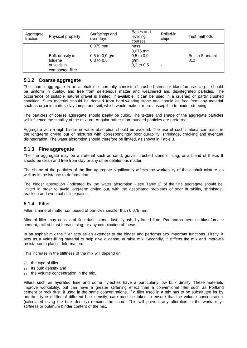
5.1.2 Coarse aggregate The coarse aggregate in an asphalt mix normally consists of crushed stone or blast-furnace slag. It should be uniform in quality, and free from deleterious matter and weathered and disintegrated particles. The occurrence of suitable natural gravel is limited; if available, it can be used in a crushed or partly crushed condition. Such material should be derived from hard-wearing stone and should be free from any material such as organic matter, clay lumps and soil, which would make it more susceptible to binder stripping. The particles of coarse aggregate should ideally be cubic. The texture and shape of the aggregate particles will influence the stability of the mixture. Angular rather than rounded particles are preferred. Aggregate with a high binder or water absorption should be avoided. The use of such material can result in the long-term drying out of mixtures with correspondingly poor durability, shrinkage, cracking and eventual disintegration. The water absorption should therefore be limited, as shown in Table 3.
5.1.3 Fine aggregate The fine aggregate may be a material such as sand, gravel, crushed stone or slag, or a blend of these. It should be clean and free from clay or any other deleterious matter. The shape of the particles of the fine aggregate significantly affects the workability of the asphalt mixture as well as its resistance to deformation. The binder absorption (indicated by the water absorption - see Table 2) of the fine aggregate should be limited in order to avoid long-term drying out, with the associated problems of poor durability, shrinkage, cracking and eventual disintegration.
5.1.4 Filler Filler is mineral matter composed of particles smaller than 0,075 mm. Mineral filler may consist of flue dust, stone dust, fly-ash, hydrated lime, Portland cement or blast-furnace cement, milled blast-furnace slag, or any combination of these. In an asphalt mix the filler acts as an extender to the binder and performs two important functions. Firstly, it acts as a voids-filling material to help give a dense, durable mix. Secondly, it stiffens the mix and improves resistance to plastic deformation. This increase in the stiffness of the mix will depend on: ?? the type of filler; ?? its bulk density and ?? the volume concentration in the mix. Fillers such as hydrated lime and some fly-ashes have a particularly low bulk density. These materials improve workability, but can have a greater stiffening effect than a conventional filler such as Portland cement or rock dust, if used in the same concentrations. If a filler used in a mix has to be substituted for by another type of filler of different bulk density, care must be taken to ensure that the volume concentration (calculated using the bulk density) remains the same. This will prevent any alteration in the workability, stiffness or optimum binder content of the mix.

Hydrated lime fillers enhance the adhesion of binder to stone, and are sometimes used to avoid stripping of binder from the aggregate. Furthermore, hydrated lime has been shown to improve the durability of binders by retarding their oxidative hardening.
5.1.5 Binder Bitumen should conform to the latest revision of SABS Method 307: Penetration Grade Bitumens4. In general, 40-50 or 60-70 pen bitumens are used to produce gap- and semi-gap-graded mixes, 60-70 or 80-100 pen for continuously-graded mixes and DBM, and 60-70 pen for open-graded mixes. The appropriate grade of binder is selected to meet the required mix design criteria. Tars should be of the low-volatile type, of either coke-oven or Lurgi origin. Although tars can be used successfully as bases, experience has shown that when tars are used in asphalt surfacings they generally produce a material with a lower durability than that produced by the use of a penetration grade bitumen. However, there are instances where tar binders have certain advantages, e.g. where the service life required is such that it is more economical to use tar. In cases where oil or fuel spillage is expected tar mixtures can be more durable than other binders. Tar should conform to the latest revision of SABS Method 748/749: Road Tar Binders.
5.2 MIX DESIGN PROCEDURES AND CRITERIA Once potentially suitable materials have been located and representative samples have been obtained, the next step in the mix design process is to conduct a laboratory investigation. Asphalt mix design demands attention to the details of design test procedures. Written instructions must be followed and a proper training in laboratory techniques is necessary. Most of the standard test procedures are described in TMH16. The laboratory investigation involves: (a) Preparation of trial mixes. The recommended aggregate grading envelopes for the different mix types, together with their nominal mix proportions, are given in Tables 3 and 4 for surfacing and base mixtures respectively. These nominal mix proportions are typical for the different mix types. They should be used as a guide to the selection of the range of binder contents to be investigated. (Refer to Appendix A for a procedure to blend various stone sizes to a given aggregate grading.) (b) Testing of compacted specimens to determine their density, voids content and permeability. (c) Testing of the mechanical properties of the mixes at specified temperatures to give an indication of their expected performance. (d) Comparison of the results of the tests on the specimens with criteria developed from field performance, to determine optimum mix proportions (Table 5).

TABLE 3 Grading envelopes and nominal mix proportions for surfacing mixtures
GAP-GRADED SEMI-GAP-GRADED CONTINUOUSLY-
GRADED OPEN-GRADED
SIEVE SIZE
(mm)
HIGH STONE
CONTENT
INTERMEDIATE STONE
CONTENT
LOW STONE
CONTENT 19mm
NOMINAL 13,2mm
NOMINAL COARSE MEDIUM FINE COARSE FINE SEMI-
OPENGRADED
26500 - - - 100 - - - - - - -
19000 100 100 100 92-100 100 100 - - 100 - 100
13200 75-100 75-100 75-100 82-93 82-100 84-100 100 - 90-100 100 70-100
9500 65-85 70-90 70-90 72-87 73-86 70-92 82-100 100 35-65 74-100 50-82
4750 50-60 60-70 65-75 50-64 52-65 50-70 54-75 64-88 6-16 12-26 16-38
2360 45-55 53-63 60-70 40-52 40-52 37-55 38-57 46-70 4-14 5-15 8-22
1180 45-55 53-63 60-70 36-47 36-47 26-41 27-42 35-54 - - 4-15
0,600 36-52 45-63 55-70 32-42 32-42 16-28 18-32 24-40 - - 3-10
0,300 25-45 35-55 45-65 22-35 22-35 12-20 13-23 16-28 3-8 3-8 3-8
0,150 12-32 15-35 20-40 10-20 10-20 8-15 9-16 10-20 - - 2-6
CU
MU
LATI
VE
PE
RC
EN
TAG
E B
Y
MA
SS
PA
SS
ING
SIE
VE
0,075 5-12 5-12 5-12 4-10 4-10 4-10 4-10 4-12 2-5 2-5 1-4
AGGREGATE 92,0% 92,0% 92,0% 92,5% 92,5% 93,5% 93,0% 93,0% 93,0% 93,0% 90,5%
BITUMINOUS BINDER 7,0% 7,0% 7,0% 6,5% 6,5% 5,5% 6,0% 6,0% 6,0% 6,0% 8,5%
NO
MIN
AL
MIX
P
RO
PO
RT
ION
S
(BY
MA
SS
)
ACTIVE MINERAL FILLER 1,0% 1,0% 1,0% 1,0% 1,0% 1,0% 1,0% 1,0% 1,0% 1,0% 1,0%

TABLE 4 Grading envelopes and nominal mix proportions for bases SEMI-GAP CONTINUOUSLY-GRADED
SIEVE SIZE (mm) 26,5mm
NOMINAL 19mm
NOMINAL 26,5mm
NOMINAL 19mm
NOMINAL
DENSE BITUMEN
MACADAM
53,000 - - - - 100
37,500 100 - 100 - 85-100
26,500 85-100 100 84-94 100 69-93
19,000 75-95 92-100 71-84 85-95 62-84
13,200 66-86 82-93 58-74 71-86 53-73
9,500 60-80 72-87 50-67 62-78 47-67
6,700 60-75 40-60
4,750 45-60 50-64 36-53 42-60 34-53
2,360 40-52 40-52 25-42 30-48 24-40
1,180 36-47 36-47 17-34 22-38 15-30
0,600 32-42 32-42 14-28 16-28 8-21
0,300 22-35 22-35 10-22 12-24 3-14
0,150 10-20 10-20 7-17 8-15 CU
MU
LATI
VE
PE
RC
EN
TAG
E B
Y M
AS
S
PA
SS
ING
SIE
VE
0,075 4-10 4-10 5-12 5-10 4-6
AGGREGATE 93% 94,5% 95% BITUMINOUS
BINDER 6% 5% 4,5%
WH
EN
B
ITU
ME
N IS
U
SE
D
ACTIVE MINERAL FILLER 1% 0,5% 0,5%
AGGREGATE 92,5% 94% %
ROAD TAR 6,5% 5,5% 5,0%
NO
MIN
AL
MIX
PR
OP
OR
TIO
NS
(B
Y M
AS
S)
WH
EN
TA
R
IS U
SE
D
ACTIVE MINERAL FILLER 1,0% 0,5% 0,5%
5.2.1 Design of gap-, semi-gap-, and continuously-graded mixes
5.2.1.1 Design method The aggregate grading, binder type, binder grade and filler which have been provisionally selected must be evaluated using the relevant methods. These are listed below. TMH1, Method C1 - The determination of a suitable binder content for use in an asphalt mix6. TMH1, Method C2 - The determination of the resistance to flow of a cylindrical briquette of a bituminous mixture by means of the Marshall apparatus6. TMH1, Method C3 - The determination of the bulk relative density of a compacted
bituminous mixture and the calculation of the voids content6. TMH1, Method C4 - The determination of:
(a) the maximum theoretical relative density of asphalt mixes (Rice's method) and (b) the quantity of bituminous binder absorbed by the aggregate6.
TMH1, Method C5 - The determination of the immersion index of a bituminous mixture6. TMH1, Method C6T - Tentative method for the determination of the creep characteristics of asphalt mixes6. RR 183-10 - Development of a mixture design procedure for recycled asphalt mixtures7. (Centre for Highway Research) All the tests described in the methods are conducted on Marshall briquettes. The results of the above test programme can now be compared with the criteria in Table 5, to enable an optimum mix composition to be formulated.

TABLE 5 Test requirements of gap-, semi-gap-, and continuously-graded mixes* TRAFFIC CLASS* E4 E3 =E2 PROPERTY MINIMUM MAXIMUM MINIMUM MAXIMUM MINIMUM MAXIMUM
TEST METHODS
MARSHALL - STABILITY kN
8 18 7 15 4 10 TMH1;C2
MARSHALL - FLOW mm 2 4 2 4 2 5 TMH1;C2
STABILITY/ FLOW kN/mm
2,5 - 2 - 2 - TMH1;C2
CREEP MODULUS @ 40 ºC Mpa 80 - 60 - 35 - TMH1;C6T
INDIRECT TENSILE STRENGTH @ 25 ºC
800 - 800 - 800 - ASTM
AIR VOIDS %† 3 6 3 6 2 5 TMH1;C3 IMMERSION INDEX % 75 - 75 - 75 - TMH1;C5
*Refer to table below. †Air voids as high as 10 % can be permitted in gap- and semi-gap-graded mixes provided that the air permeability requirement is met.
TRAFFIC CLASS CUMULATIVE EQUIVALENT TRAFFIC (E80s/LANE) E4 12 - 50 x 106 E3 3 - 12 X 106 E2 0,8 - 3 x 10⁶ E1 0,2 - 0,8 X 10⁶
5.2.1.2 Special design considerations for gap- and semi-gap-graded mixes (i) Ratio of filler to binder The filler plays a very important part in providing tensile strength, stiffness and resistance to plastic deformation of gap- and semi-gap-graded mixes. Too low a filler to binder ratio may result in low resistance to plastic deformation and inadequate tensile strength, whereas too high a ratio may result in a very stiff and brittle mix. The ration of filler to binder therefore needs to be controlled. Lower and upper limits of 1 and 1,5 respectively are recommended.

FIGURE 2 Bureau of Public Roads chart for aggregate gradation analysis
(ii) Air permeability In the case of gap- and semi-gap-graded mixes, it is recommended that the air permeability of the compacted Marshall specimens be determined separately in accordance with the method detailed in Appendix C. The variety of sands used in these mixes means that a wide range of air voids contents can be obtained at the same permeability value. It is therefore not possible to control permeability by controlling only the voids in the mix. This would be restrictive, excluding certain useful mixes which have a relatively high voids content but which are still sufficiently impermeable to give durable mixes (particularly in the case of mine dump sand). A maximum air permeability of 1 X 10⁻⁸ cm2 is recommended. It is unnecessary to test mixes that have voids contents below 5 % for air permeability. (iii) Film thickness In order to ensure that enough binder is available to produce a durable mixture, it is advisable to calculate the average film thickness of binder in the mix (using the method detailed in Appendix B) and to ensure that this does not fall below 5 µm.

5.2.1.3 Special design considerations for continuously-graded mixes (i) Aggregate grading The grading of continuously-graded mixes is usually determined using the US Bureau of Public Roads gradation chart given in Figure 2. The maximum aggregate size should not be more than half of the layer thickness. The maximum density curve on the chart is then obtained by drawing a horizontal line from the origin to the maximum size of aggregate. This chart is convenient for use in adjusting aggregate gradings: gradings coming too close to this line need to be adjusted. This will entail increasing the voids in mineral aggregate (VMA), thereby allowing sufficient binder into the mix to meet durability requirements. Table 6 gives the recommended minimum VIVIA values for different maximum aggregate sizes, while typical aggregate grading envelopes are given in Tables 3 and 4 for surfacing and base mixes respectively. TABLE 6 Recommended minimum voids in mineral aggregate (VMA) values for continuously-graded
mixes Max size of aggregate
(mm) Min VMA
% of asphalt mix 37,5 12,0 26,5 13,0 19,0 14,0 13,2 15,0 9,5 16,0
When continuously-graded mixes are used for surfacings, a maximum air permeability of 1 X 10⁻⁸ cm2 is recommended.
5.2.2 Design of DBM mixes
5.2.2.1 Design method The key to the successful design of DBM mixes is to select an aggregate grading which maximizes the inter-particle friction of all aggregate fractions. A design method based on limited local and overseas research is proposed. This method places more emphasis on the determination of an appropriate aggregate grading than is the case with other mix types, and considers aggregate shape and packing characteristics. The method involves making a series of aggregate gradings with varying equivalent fines contents. (The equivalent fines content of an aggregate grading is defined as the percentage material by mass passing a sieve having a size equal to 0,03 the maximum aggregate size.) The relationship:
? ?? ?? ? FD
dFP
nn
nn
??
???
075,0075,0100
where P = percentage by mass passing a sieve of size d mm D = maximum aggregate size (mm) F = percentage filler content (i.e. the material by mass passing the 0,075 mm sieve) n = variable dependent on aggregate packing characteristics is used to prepare the grading curves with varying equivalent fines contents, after fixing the filler at a predetermined level. The steps to be taken are as follows: ?? Determine the filler content. For DBM base mixes used in South Africa a filler content of 4 to 6 % is
appropriate. ?? Make up a series of dry aggregate mixtures, the gradings of which have been determined using the
above equation. The values of n should be selected to give a range of equivalent fines contents from 15 to 30 %, as shown in Figure 3 (for a maximum aggregate size of 37,5 mm and filler content fixed at 5 %). The typical aggregate grading envelope for DBM mixes is given in Table 4.

?? Compact these mixes using dry aggregate as described in TMH1 Method A11T6. Measure the bulk volume and calculate the VMA of the dry aggregate.
?? Plot the VIVIA of the dry aggregate versus n and determine the optimum n-value for minimum VMA. This optimum n-value will define the optimum grading in Figure 3.
?? Adjust the n-value so that the equivalent fines content is 80 to 90 % of that for the optimum grading. This is the target design grading. This step is necessary to allow sufficient binder into the mix for reasons of durability, even though the optimum grading would result in the optimum dry aggregate packing.
When determining the appropriate binder content, there is as yet no practical method to compact an asphalt mix specimen when the maximum particle size exceeds 26,5 mm. It is suggested that for mixes containing aggregates exceeding 26,5 mm a model grading should be used to ensure adequate compaction in a Marshall mould. The model grading should have a maximum aggregate size of 26,5 mm and a grading curve with the same n-value as the target design grading. The design method and criteria to be applied to samples prepared using the model grading will then be identical to those described for continuously-graded mixes.
FIGURE 3 Grading curves resulting from the relationship ? ?? ?
? ? FD
dFP
nn
nn
??
???
075,0075,0100

5.2.3 Design of open-graded mixes Open-graded mixes are used mainly to improve skid resistance. The macrotexture required for this is more or less assured if the recommended aggregate gradations given in Table 3 are adhered to. The limits given for the 2,36 mm sieve are intended primarily as a guide. The consideration which determines the maximum limit in practice is that all the finer material must fit within the interstitial voids of the composite-forming material (retained on the 2,36 mm sieve). The uniformity of the grading between the 2,36 mm and 0,075 mm sieve and the shape characteristics of the coarse aggregate tractions are important factors which affect the quantity that can be used. The importance of having at least some fine aggregate must be emphasized. Its primary purpose is to provide a supporting matrix, stiffening the binder and hereby stabilizing the coarse aggregate skeleton. Consequently, minimum requirements have been specified. The limits given for the filler (passing the 0,075 mm sieve) ensure a uniform grading of the fine aggregate. They also control the bitumen drainage characteristics of the mixture by effectively increasing the viscosity of the bitumen conditions. These grades should be considered as a starting point; test results obtained during the design process may indicate that it would be advantageous or necessary to alter the bitumen grade. To ensure maximum durability of this type of mixture, as much bitumen as is practically possible should be introduced into the mix. In order to ensure the free-draining characteristics of an open-graded asphalt, the voids content should not be less than 15 %. It will usually lie between 15 and 18%. Design methods for open-graded mixes have yet to be proven for South African conditions. A tentative method is therefore suggested for interim use, details of which are given in Appendix D.
5.3 SPECIAL DESIGN CONSIDERATIONS FOR AIRPORTS AND PARKING AREAS The traffic classes defined in Table 5 cannot be applied directly to airport and parking area traffic. It is recommended that the criteria set for class E4 traffic be applied to large airports and to parking areas carrying heavy traffic, and that the criteria for class E2 traffic be applied to small airfields and to parking areas carrying light traffic. Compared to normal roads, the intensity of aircraft and parking area traffic is relatively low. The life of asphalt layers is therefore primarily dictated by their durability, and special attention should thus be given to the factors controlling it, i.e. density, air voids and binder film thickness. The air voids content should be restricted to between 2 and 4 %, while the highest binder content which meets the other required properties listed in Table 5 should be selected.

6 QUALITY ASSURANCE As with other manufactured products, hot-mix asphalt requires careful quality control during both the manufacturing and construction phases to ensure that the product consistently complies with the specifications8. Even a well-designed mix can give poor performance, unless produced within acceptable tolerances of binder content and aggregate grading. The binder content of the mix is generally regarded as the most critical constituent.

REFERENCES 1. NATIONAL INSTITUTE FOR TRANSPORT AND ROAD RESEARCH. Selection and design of hot-mix asphalt surfacings for highways. Draft TRH8, Pretoria, CSIR, 1978. 2. NATIONAL INSTITUTE FOR TRANSPORT AND ROAD RESEARCH. Cementitious stabilizers in road construction. Draft TRH13, Pretoria, CSIR, 1986. 3. NATIONAL INSTITUTE FOR TRANSPORT AND ROAD RESEARCH. Guidelines for road construction materials. TRH14, Pretoria, CSIR, 1985. 4. SOUTH AFRICAN BUREAU OF STANDARDS. Standard specification for penetration grade bitumens. SABS Method 307, Pretoria, SABS, 1974. 5. SOUTH AFRICAN BUREAU OF STANDARDS. Road tar binders. SABS Method 748/749, Pretoria, SABS. 6. NATIONAL INSTITUTE FOR TRANSPORT AND ROAD RESEARCH. Standard methods of testing road construction materials. TMH1, Pretoria, CSIR, 1986. 7. CENTRE FOR HIGHWAY RESEARCH. Development of a mixture design procedure for recycled asphalt mixtures. Research Report 183 – 10, the University of Texas at Austin, November 1978. 8. NATIONAL INSTITUTE FOR TRANSPORT AND ROAD RESEARCH. Statistical concepts of quality assurance and their application in road construction. Draft TRH5, Pretoria, CSIR, 1977. 9. ASTM D2170 – 67. Standard Method of Test for kinematic viscosity of asphalts.
FURTHER READING 1. ANNUAL TRANSPORTATION CONVENTION. Bitumen-rubber: Review of developments in South Africa. (Edited by V P Servas). Symposium presented by the National Institute for Transport and Road Research and by the Road Industry, Pretoria, 7 August 1984. 2. CAPSA 1984. Proceedings of the Fourth Conference on Asphalt Pavements for southern Africa, Volume 1, Cape Town, 12 - 16 March 1984. 3. COOPER, K E and POOLEY, G R. The design of aggregate gradings for asphalt basecourses. Paper presented to Symposium on "Asphalt Mix Design" at the Annual Meeting of the Association of Asphalt Paving Technologists, San Antonio, Texas, 11 - 13 February, 1985. 4. EICK, J H and SHOOK, J F. The effects of baghouse fines on asphalt mixtures. A preprint of a paper prepared for presentation at the Canadian Technical Asphalt Association Annual Conference, Winnipeg, 1978, Asphalt Institute Research Report 78–3 (RR–78–3), Maryland, November 1978. 5. FRANCKEN, L. Fatigue performance of a bituminous road mix under realistic test conditions. Extract from "Bituminous Materials and Skid Resistance", Transportation Research Record 712, Transportation Research Board, National Academy of Sciences, Washington DC, 1979. 6. FREEME, C R. The behaviour of bituminous surfacings in asphalt pavements. Ph D dissertation, University of Natal, Durban, 1971. 7. FREEME, C R, DE BEER, M and VILJOEN, A W. The behaviour and mechanistic design of asphalt pavements. Paper presented to the 8th International Conference on the Structural Design of Asphalt Pavements, University of Michigan, Ann Arbor, Michigan, USA, 13–17 July 1987. 8. FREEME, C R and MARAIS, C P. Traffic-load associated cracking of asphalt pavements. Proc. 2nd Conference on Asphalt Pavements for Southern Africa, Durban, CSIR, 1974, pp 1–135 to 1–151 (CSIR Reprint RR 166). 9. FREEME, C R, MAREE, J H and VILJOEN, A W. Mechanistic design of asphalt pavements and verification using the Heavy Vehicle Simulator. Proceedings of the 5th International Conference on the Structural Design of Asphalt Pavements, Vol 1, Delft, Holland, 1982, pp 156–173. 10. HUGO, F. A critical view of asphalt mixes in current use with proposals for a new mix. Proc. 1st Conference on Asphalt Pavements for Southern Africa, Durban, CSIR, 1969, pp 8A/1–8A/28. 11. HUGO, F. A critical review of bituminous mixtures at present being used for surfacing pavements with proposals for the composition and design of mixtures suitable for South African conditions. MSc thesis. University of Natal, Durban, 1970. 12. HUGO, F. Toetse om die verouderingsgedrag van asfaltmengsels te evalueer. Proceedings of Annual Transportation Convention, Pretoria, 1985. 13. MARAIS, C P. Advances in the design and application of bituminous materials in road construction. D Phil. University of Natal, Durban, 1979. 14. MAREE, J H. and FREEME, C R. The mechanistic design methods used to evaluate the pavement structures in the catalogue of the Draft TRH4 (1980). NITRR Technical Report RP/2/81, Pretoria, CSIR, 1981. 15. MYBURGH, P A and DUMAS, N B. Motivations for the adoption of a statistical acceptance scheme. CRM81/3, Cape Provincial Administration, Department of Roads, Cape Town, August 1981.

16. MYBURGH, P A and DUMAS, N B. Theoretical background of quality control, specifically the acceptance criterion. CRM81/3, Cape Provincial Administration, Department of Roads, Cape Town, August 1981. 17. MYBURGH, PA and DUMAS, NB. Rejection of doubtful observations. CRM81/3, Cape Provincial Administration, Department of Roads, Cape Town, August 1981. 18. NATIONAL INSTITUTE FOR TRANSPORT AND ROAD RESEARCH. Structural design of interurban and rural road pavements. Draft TRH4, Pretoria, CSIR, 1980. 19. NATIONAL INSTITUTE FOR TRANSPORT AND ROAD RESEARCH. Sampling methods for road construction materials. TMH5, Pretoria, CSIR, 1981. 20. NATIONAL INSTITUTE FOR TRANSPORT AND ROAD RESEARCH. Surfacing seals for rural and urban roads and a compendium of design methods for surfacing seals used in the Republic of South Africa. Draft TRH3, Pretoria, CSIR, 1986. 21. NATIONAL TRANSPORT COMMISSION. Standard specifications for road and bridge works. Pretoria, Directorate Land Transport, revised September 1980. 22. PEREZ, I, KENNEDY, T W and ADEDIMILA, A S. Development of a mixture design procedure for recycled asphalt mixes. Research Report 183–10. Centre for Highway Research. University of Texas at Austin. November 1978. 23. SERVAS, V P, et al. The effect of the proportion of reclaimed asphalt on aspects of the quality of recycled mixes. Paper presented to the 1986 International Conference on Bearing Capacity of Roads and Airfields, Plymouth, England, 1986. 24. SMITH, R W, RICE, J M and SPELMAN, S R. Design of open-graded asphalt friction courses. Report No FHWA–RD–74–2, Federal Highway Administration, Washington DC, 1974. 25. STUDY CENTRE FOR ROAD CONSTRUCTION, THE NETHERLANDS. Proceedings of the International Symposium on Porous Asphalt. S.C.W. Record 2, Amsterdam, Holland, 1976. 26. THE ASPHALT INSTITUTE. Design of hot asphalt mixtures. Educational Series No 3 (ES-3), Maryland 20740, July 1979. 27. THE ASPHALT INSTITUTE. Mix design methods for asphalt concrete and other hot-mix types. Manual Series No 2 (MS-2), Maryland 20740, March 1979. 28. VILJOEN, A W. Heavy-vehicle simulator test results on a bituminous pavement on Route N3 near Hammersdale in Natal. NITRR Technical Report RP/4/80, Pretoria, CSIR, 1980. 29. VISSER, A T. An investigation of the skid resistance of roads under South African conditions. MSc thesis. University of the Witwatersrand, Johannesburg, 1974. 30. HUGO, F and KENNEDY, T W. Surface cracking of asphalt mixtures in southern Africa. Proceedings of the Annual Meeting AAPT, Volume 54, San Antonio, Texas, 1985. 31. HUGO, F. Tests for evaluating the ageing behaviour of asphalt. Annual Transportation Convention. Pretoria, August 1985. 32. HUGO, F, SNYMAN, D R F and SERVAS, V P. HVS-aided validation of pavement behaviour at low temperature. Proceedings of the Annual Meeting AAPT, Volume 56, Reno, February 1987. 33. HUGO, F. Catering for long term changes in the characteristics of asphalt during the design life of a pavement. Volume 1, Proceedings of the 6th international Conference on Asphalt Paving, Ann Arbor, Michigan, July 1987.
DEFINITIONS Asphalt - a mix of aggregate, mineral filler (if required) and bituminous binder in predetermined, accurately controlled proportions. Asphalt base - an asphalt layer occurring immediately beneath the surfacing and over the subbase, or, if there is no subbase, over the selected layers. Asphalt surfacing - an asphalt mixture laid on the base of a pavement and over which the traffic passes. Binder - a term used to describe any material that is used in road construction processes to bind together aggregate or soil particles. In this document, only bituminous binders (i.e. bitumen- or tar-based materials) are considered. Bitumen - a viscous black liquid derived from petroleum by a refinery process. Bitumen/Tar content - the content of bitumen/tar in an asphalt mixture expressed as a percentage by mass of total mixture. Coarse aggregate - the aggregate fraction of an asphalt mixture that is retained on a 4,75 mm sieve. Continuously-graded asphalt - an asphalt mixture composed of mineral particles which are evenly distributed in size fractions from coarse to fine, and filler. Dense bitumen macadam (DBM) - a very coarse and densely graded continuously-graded asphalt. Filler - mineral matter composed of particles smaller than 75 µm. Fine aggregate - the aggregate fraction of an asphalt mixture that substantially (at least 90 %) passes a 4,75 mm sieve, and is retained on a 0,075 mm sieve.

Gap-graded asphalt - an asphalt mixture composed of mineral particles with certain intermediate sizes missing from the size range, and filler. Modified binder - a bitumen or tar, the properties of which have been modified by the addition of compounds so that performance is enhanced. Examples of modifiers are plastic compounds such as PVC and natural or synthetic rubbers. Open-graded asphalt - an asphalt mixture composed of mineral particles and filler so constituted as to give a high air voids content when in the compacted state. Penetration grade bitumen - that fraction of petroleum crude oil that is solid or nearly solid at normal air temperature and that is blended or further processed to produce bituminous products of varying hardness or "penetration". Recycled asphalt - a mixture of reclaimed asphalt and new binder, aggregate and rejuvenating agent (if required). Semi-gap-graded asphalt - an asphalt mixture composed of mineral particles with certain intermediate sizes missing from the size range, and filler. The coarse aggregate fraction is more graded than that of gap-graded asphalt. Tar - a viscous black liquid derived from the destructive distillation of coal.

APPENDIX A : Blending of various stone sizes to a given aggregate grading The investigation of asphalt surfacing mixtures for design purposes should be based on an aggregate grading which can be realistically produced in the hot-mix asphalt plant to be used during construction. The first step in determining the jobmix grading is to combine the various stone fractions that will be available during construction to approximate as closely as possible the design or specification grading required. The best way of doing this is to obtain samples of the hot-bin fractions (in the case of a plant with hot screening) or to use the various fractions from the stockpile material. The proportions in which the various fractions should be combined to produce the desired grading can be investigated by various graphical or mathematical methods. The method described by Rothfuchs has been found most useful as it is reasonably quick and simple and can be applied to blends of any number of components. It consists essentially of the following stages: 1. The cumulative curve of the design aggregate's particle-size distribution is plotted, using the usual linear ordinates for the percentage passing, but choosing the scale of sieve sizes which allows the particle-size distribution to be plotted as a straight line. This is readily done by drawing an inclined straight line and marking on it the sizes corresponding to the various percentages passing. 2. The particle-size distribution curves of the stone fractions (including filler) to be mixed are plotted on this scale. It will generally be found that they are not straight lines. 3. With the aid of a transparent straight-edge, the straight lines which most nearly approximate the particle-size distribution curves of each component are drawn. This is done by selecting for each curve a straight line such that the areas enclosed between it and the curve are minimal and are balanced about the straight line. 4. The opposite ends of these straight lines are joined together and the proportions for mixing can be read from the points where these joining lines cross the diagonal straight line which represents the design grading. The procedure will be apparent from the following example: The particle-size distributions of three fractions of stone and filler available to produce the required design grading are given in Table A1. Note that for greater accuracy a wet particle-size analysis should be carried out on these components. The design or specification grading is also given in the Right-hand column of the table.
TABLE A1 Particle-size distribution of components on the basis of wet analysis
Hot-bin or cold feed samples
Sieve size (mm) A B C D
Design of spec.
grading 19,0 100 - - - 100 13,2 85 100 - - 90 6,7 30 90 - - 78 4,75 0 70 100 - 61 2,36 0 25 95 - 45 1,18 0 10 70 - 30
0,600 0 0 50 100 22 0,300 0 0 30 95 16 0,150 0 0 10 80 12 0,075 0 0 0 50 6
In Figure A1 the required grading of the blend is represented by the diagonal straight line 00I. The vertical ordinates of the grading sheet are graduated for percentages from 0 to 100 on a linear scale. The horizontal scale for sieve aperture size is graduated by drawing for each sieve size a vertical line which cuts the diagonal at a point where the ordinate equals the percentage passing that sieve, i.e. 100 % for 19,0 mm, 90 % for 13,2 mm, 78 % for 6,7 mm and so on.
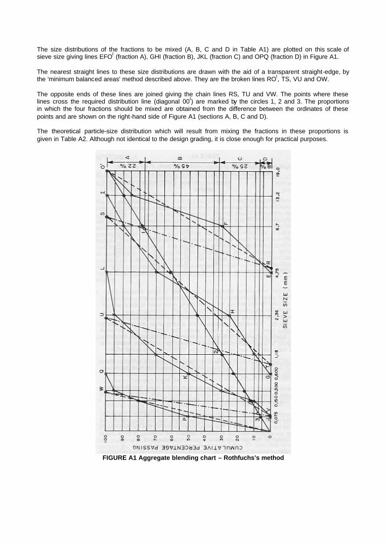
The size distributions of the fractions to be mixed (A, B, C and D in Table A1) are plotted on this scale of sieve size giving lines EFOI (fraction A), GHI (fraction B), JKL (fraction C) and OPQ (fraction D) in Figure A1. The nearest straight lines to these size distributions are drawn with the aid of a transparent straight-edge, by the 'minimum balanced areas' method described above. They are the broken lines ROI, TS, VU and OW. The opposite ends of these lines are joined giving the chain lines RS, TU and VW. The points where these lines cross the required distribution line (diagonal 00I) are marked by the circles 1, 2 and 3. The proportions in which the four fractions should be mixed are obtained from the difference between the ordinates of these points and are shown on the right-hand side of Figure A1 (sections A, B, C and D). The theoretical particle-size distribution which will result from mixing the fractions in these proportions is given in Table A2. Although not identical to the design grading, it is close enough for practical purposes.
FIGURE A1 Aggregate blending chart – Rothfuchs’s method

TABLE A2 Theoretical blend resulting from Rothfuchs's method
Percentage of each fraction
22% of A
45% of B
25% of C
8% of D
Total Cumulative grading
Passing (mm)
Retained (mm)
19,0 13,2 3,3 3,3 100,0 13,2 6,7 12,1 4,5 16,6 96,7 6,7 4,75 6,6 9,0 15,6 80,1 4,75 2,36 20,25 1,25 21,5 64,5 2,36 1,18 6,75 6,25 13,0 43,0 1,18 0,600 4,5 5,0 9,5 30,0
0,600 0,300 5,0 0,4 5,4 20,5 0,300 0,150 5,0 1,2 6,2 15,1 0,150 0,075 2,5 2,4 4,9 8,9 0,075 4,0 4,0 4,0

APPENDIX B : Calculation of binder film thickness The film thickness of the binder is calculated from the following formula:
610.1
.1
.100 SAB
BF e
??
where F = film thickness (µm)
Be* = effective binder content of the asphalt mixture (% by mass of mix) B = total binder content of the mixture (% by mass of mix) A = surface area of aggregate blend (m2/kg) S = density of binder at 25 ºC (kg /m3)
A, the surface area of the aggregate blend, is calculated from
? ? 20482,060,160,030,014,008,004,002,02 gfedcbaA ???????? where a = percentage passing 4,75 mm sieve
b = percentage passing 2,36 mm sieve c = percentage passing 1,18 mm sieve d = percentage passing 0,60 mm sieve e = percentage passing 0,30 mm sieve f = percentage passing 0, 15 mm sieve g = percentage passing 0,075 mm sieve
*The effective binder content (Be) of an asphalt mix is defined as the total binder content of the mix minus the quantity of binder lost by absorption into the aggregate particles. (Refer to TMH1, Method C46.)

APPENDIX C : Determination of the air permeability of compacted Marshall specimens Scope The measurement of air permeability is non-destructive and may be performed on laboratory-compacted Marshall specimens or cores removed from a pavement. Apparatus Model AP–400 A, Asphalt Paving Meter, is a self-contained device capable of measuring air flow rates of up to 5 l per minute at low pressure differentials. The apparatus and attachments are shown in Figure 5. The device has a maximum volume capacity of 1 l . It is equipped with two calibrated sight tubes; one measures in 25 ml increments for dense specimens, and the other is graduated in 500 ml increments for open, permeable specimens. Incorporated in the unit are the valves required to perform the test: a pressure squeeze bulb for filling the test system with water; a sensitive manometer for pressure setting; a metal cylindrical jacket slightly larger than the 101,6 mm diameter Marshall specimen and containing a 101,6 mm diameter rubber triaxial sleeve as an inner liner; a domed test cap; and a specimen support. Method 1. Remove either stem valve by screwing counter-clockwise and lifting out of the case. Set the main control valve at 'exhaust' or 'test'. Fill the unit with 2 000 ml of water through the recess left by the stem valve. 2. Replace the stem valve in its mounting. 3. Fill one of the two calibrated volumetric cylinders in the following manner:
NOTE: 1 000 ml cylinder is used for open specimens. 300 ml cylinder is used for dense specimens.
(a) Push the main control valve to the 'off' position. (b) Open the stem valve above the selected cylinder by turning counter-clockwise. One
revolution is adequate. Check to make certain that the volumetric cylinder stem valve not being used is closed tightly. The air flow valve on top of the rubber bulb assembly should be open (unscrewed about two turns).
(c) Squeeze the rubber bulb, pumping air into the reservoir. The pressure will force water from the reservoir into the measuring cylinder, as can be seen by the rising water-level in the sight tube. Continue pumping until the sight tube is filled to within approximately 25 mm of the top. Close the stem valve connected to this tube.
(d) Turn the main valve to the 'exhaust' position to allow excess air pressure to escape from the reservoir.
Connect the rubber tube of the specimen test cap to the pressure port located in the lower left corner of the instrument. Connect the second tube of the specimen test cap to the manometer port located at the top left of the manometer. (The rubber tubes of the test cap are interchangeable and may be connected to either the pressure port or the manometer port.)
4. Level the instrument by observing the level bubble and adjust the instrument on the swivel tripod. 5. Set the manometer at the 'zero' reading by loosening the screw at the bottom of the manometer and
sliding the scale until the 'zero' reading coincides with the level of the manometer fluid in the nearly horizontal tube of the manometer. Be sure that the manometer valves are in an open position while zeroing the manometer and during
a test. 6. The Marshall specimen is placed on the support and the metal cylinder, with the rubber triaxial
sleeve in place, is slipped over both. The domed test cap with rubber tubes attached is then placed over the top of the specimen and the rubber -sleeve inflated with the hand bulb to seal the cap, specimen and support. If the vertical face of the specimen is rough, it may be sealed with paraffin wax prior to placing in cylinder.
7. The instrument is now ready to perform the test: the main valve is set at ‘exhaust', the measuring cylinder is full, both manometer valves are open, the manometer is reading 'zero' and the test cap is sealed to the specimen.
8. Proceed as follows:

(a) Push the main control valve to the 'test' position. Close the airflow valve at the top of rubber assembly.
(b) Open the stem valve of the filled volumetric cylinder slowly, allowing water to flow from the cylinder back to the reservoir. Adjust the stem valve so that a constant pressure is developed and recorded by the manometer. Normally, tests are run at 6,4 mm of water pressure. The pressure is held constant throughout the test by minor adjustments to the stem valve.
(c) Once constant pressure has been attained, the time required for water to flow between two of the calibration marks on the sight tube is measured accurately. A volume of flow sufficiently large to require a time interval of at least 20 seconds should be selected to obtain accurately repeatable results. Time intervals exceeding 2 minutes do not add to the accuracy of the test and only prolong the testing time.
9. A minimum of three Marshall specimens should be tested at each binder content and the mean rate of air flow through the specimens taken.

FIGURE C1 Measurement of the air permeability of compacted Marshall specimens using the Asphalt
Paving Meter
Calculation The air permeability is then calculated using the following formula:
hQL
xK 910331,2 ??
where K = fundamental permeability (cm2)
Q = rate of air flow through specimen (cm3/s) L = average height of specimen (cm) h = air pressure difference expressed in height of water column (cm)
It should be noted that the above formula applies only to a 101,6 mm diameter cylindrical specimen.

APPENDIX D : Design method for open-graded asphalt Select a suitable aggregate grading from the envelope in Figure D1. Determine the bulk density for the coarse and fine aggregate fractions (retained and passing 2,36 mm sieve) using TMH1, Methods B14 and B156. Using the information on the combined grading, mathematically compute the bulk density of the combined grading (see TMH1, Method B14)6. Determine the kinematic viscosity-temperature relationship and density at 25 ºC of the bitumen selected (see ASTM D2170-67)9. Determine the surface constant of the aggregate fraction retained on a 4,75 mm sieve in accordance with the following procedure: 1 . Quarter out 105 g of material representative of that passing a 9,5 mm and retained on a 4,75 mm
sieve. 2. Dry sample on a hotplate or in 110 ± 5 ºC oven to constant mass and allow to cool. 3. Weigh out 100 g and place in a metal funnel (top diameter 89 mm, height 114 mm, orifice 13 mm,
with a piece of 2,0 mm sieve soldered to the bottom of the opening). 4. Completely immerse sample in SAE No 10 lubricating oil for 5 minutes. 5. Drain for 2 minutes. 6. Place funnel containing sample in 60 ºC oven for 15 minutes for additional drainage. 7. Pour sample from funnel into tarred pan; cool and reweigh sample to nearest 0,1 g. Subtract original
mass and record difference as percentage oil retained (based on 100 g of dry sample). 8. Use chart shown in Figure D1 for determination of ‘KC'. NOTE:
(a) If the relative density of fraction is greater than 2,70 or less than 2,60 apply correction to oil retained, using the formula at the bottom of Figure D1.
(b) Start at the bottom of chart in Figure D1 with the corrected percentage of oil retained; follow the straight-edge vertically upward to the intersection with the diagonal line; hold the point, and follow the straight-edge horizontally to the left. The value obtained will be the surface constant for the retained fraction and is known as ‘KC'.
9. Determine the required bitumen content, which is based on mass of aggregate, from the following relationship:
Percentage bitumen (B) = 2,0 (KC) + 4,0 No correction need be applied for bitumen grade.
10. Determine the compacted density and void capacity of the coarse aggregate fraction (material retained on 2,36 mm sieve) of the proposed gradation using the following procedure: Apparatus Standard Marshall compaction equipment is used. Procedure Prepare 1 kg of the mixture using the bitumen content determined above, and mix at 130 ºC using 60/70 penetration grade bitumen.

FIGURE D1 Chart for determining the surface constant (KC) of coarse aggregate
Apply 45 blows to each face of the specimen using the standard Marshall hammer. Commence compaction when the mix is at 115 ºC. Care should be taken that the compacted specimen does not deform during the cooling period. After extrusion from the metal mould, the height of the cooled specimen should be carefully determined to the nearest 0,01 mm. Calculations Calculate the compacted bulk density (X) as follows:
? ?? ?3
2
3
1094
mkgtd
m
msampleofVolume
kgsampleofMassx
????
????
?
?
where m = mass of specimen in kg
d = diameter of mould in mm t = height of compacted specimen in mm
Calculate the voids in the mix, assuming no bitumen absorption by the aggregate, as follows:
100???
??? ?
?Dm
xDmVm
where Vm = voids in mix (%)
Dm = max theoretical density of mixture (kg/m3)

X = bulk density of compacted mix (kg/ m3)
where
SP
GA
Dm
ag
??
100
A = percentage total aggregate by mass in mix P = percentage bitumen by mass in mix Gag = bulk density of aggregate (kg/m3) S = density of bitumen (kg/m3)
Optimum mixing temperature To determine the optimum mixing temperature to be used in practice prepare 1 kg sample of aggregate and bitumen at the bitumen content determined, and mix at a temperature corresponding to a bitumen kinematic viscosity Of 0,8 x 10⁻³ m2/s (800 centistokes). When completely coated, transfer the mixture to a pyrex plate (200 - 230 mm diameter) and spread using a minimum of manipulation. Return to the oven at the mixing temperature. Observe the bottom of the plate after 15 to 60 minutes. There should be a slight puddle at points of contact between the aggregate and the glass plate. If this is not present, repeat the test at a lower mixing temperature, and again at a higher one if necessary. NOTE: If bitumen drainage occurs at a mixing temperature which is too low to ensure adequate drying of the aggregate, bitumen of a lower penetration should be used. Resistance to effects of water To ensure the resistance of the open-graded asphalt to water, add 1,5 % by mass of hydrated lime to the designed mixture.


