31
DRAINAGE AND WATER MANAGEMENT v3.0 CONCRETE PIPES PRECAST TANK SYSTEMS EASI-BASE MANHOLE SYSTEM HEADWALLS

DRAINAGE AND WATER MANAGEMENT v3.0
coNcRETE pIpEs
pREcAsT TANk sysTEMs
EAsI-bAsE MANholE sysTEM
hEADWAlls

DRAINAGE AND WATER MANAGEMENT
The Benefits of Concrete Drainage 4Spigot & Socket Pipes 6FPM Tools Autocad 8Oblique Tumbling Junction 9Square Tumbling Junction 10Pipe Handling/Laying Instructions 11Anchor System 13Pipe Lifting Instructions 14Pipe Jointing Guide 15Pre-Lubricated Pipes 16Manhole Chambers 17Recommended Site Work Practice 18Manhole Soakaways 18Dn4000 Manhole Chamber 19Dn4000 Lifting, Handling & Installation Guide 19Manhole Construction 20Easi-Base™ 1200 21Easi-Base™ 1500-2400 22Easi-Base™ Order Form 23Dn1050 Highways Agency Catchpit 24Catchpit 25Flow Control Chamber 26Valve Chamber 26Stormbrake™ - Vortex Flow Controller 27Wide Wall Manhole Chamber 28Manhole Cover Slabs & Accessories 30Adjusting Units & Corbel Slabs 31Gullies and Slabs Range 32Fall Arrest System 33House Inspection Chambers 34Add-A-Step™ 35Plastic Encapsulated Ladders & Rungs 36Handhold Entry Pole System 37Headwalls 38StormCleanser™ - Hydrodynamic Seperator 40Rain Harvesting Chambers 41Mechanical Concrete Pipe Lifter 42-45Stormstore™ 46-49Stormhold™ 50-52Dry Weather Flow Channels 53Precast Tanks & Chambers 54Paramatic Design 55Multipurpose Chamber System 56Multipurpose Panel System 57Box Culverts 58
With one of the largest drainage and water management product ranges in the UK and Ireland, FP McCann has become the first choice for all of our customers.
FP McCann is the UK’s market leader in the manufacture, supply and delivery of precast concrete solutions. Our comprehensive precast concrete business extends to include:
AGRIculTuRE | ARchITEcTuRAl pREcAsT | box culvERTs | buIlDING pRoDucTs Dock lEvEllERs | DRAINAGE | FENcING | FIlTER bED sysTEMs | FlooRING poWER & INFRAsTRucTuRE | RAIl | spEcIAlIsT pREcAsT | sTRucTuRAl pREcAsT TANks & chAMbERs | TuNNEls & shAFTs | WAllING
Modern manufacturing plants at Alnwick (Northumberland), Armagh (Northern Ireland), Byley (Cheshire), Cadeby (Warwickshire), Ellistown (Leicestershire), Grantham (Lincolnshire), Lisnaskea (Northern Ireland), Littleport (Cambridgeshire), Lydney (Gloucestershire), Magherafelt (Northern Ireland), Uddingston (Lanarkshire) and Weston Underwood (Derbyshire) incorporate the latest computerised batching, distribution, casting, curing and handling systems and are operated by skilled and experienced workforces to ensure consistency of quality. Their geographical spread gives us an unrivalled ability to serve the construction industry throughout the UK and Ireland.
By applying the DFMA principles, FP McCann’s design engineers are able to evaluate individual precast concrete products part by part, in addition to documenting the assembly process step by step. This allows them to generate the cost, part count and assembly time to provide a benchmark to measure its success and identify the parts and process improvement opportunities. In turn, this has allowed FP McCann to design and manufacture more cost-effective and efficient high-quality precast concrete products with less wastage and greater on-site recycling. As a result, increased productivity, combined with a reduction in production time and costs, allows FP McCann to be more competitive within the marketplace.
Please note: all information is correct at time of going to print.
lyDNEy
MAGhERAFElT
cADEby
GRANThAM
lITTlEpoRT
AlNWIck
WEsToN uNDERWooDEllIsToWN
bylEy
lIsNAskEA
WEllEsbouRNEloNDoN
uDDINGsToN
ARMAGh
FpMccANN.co.uk
mpa
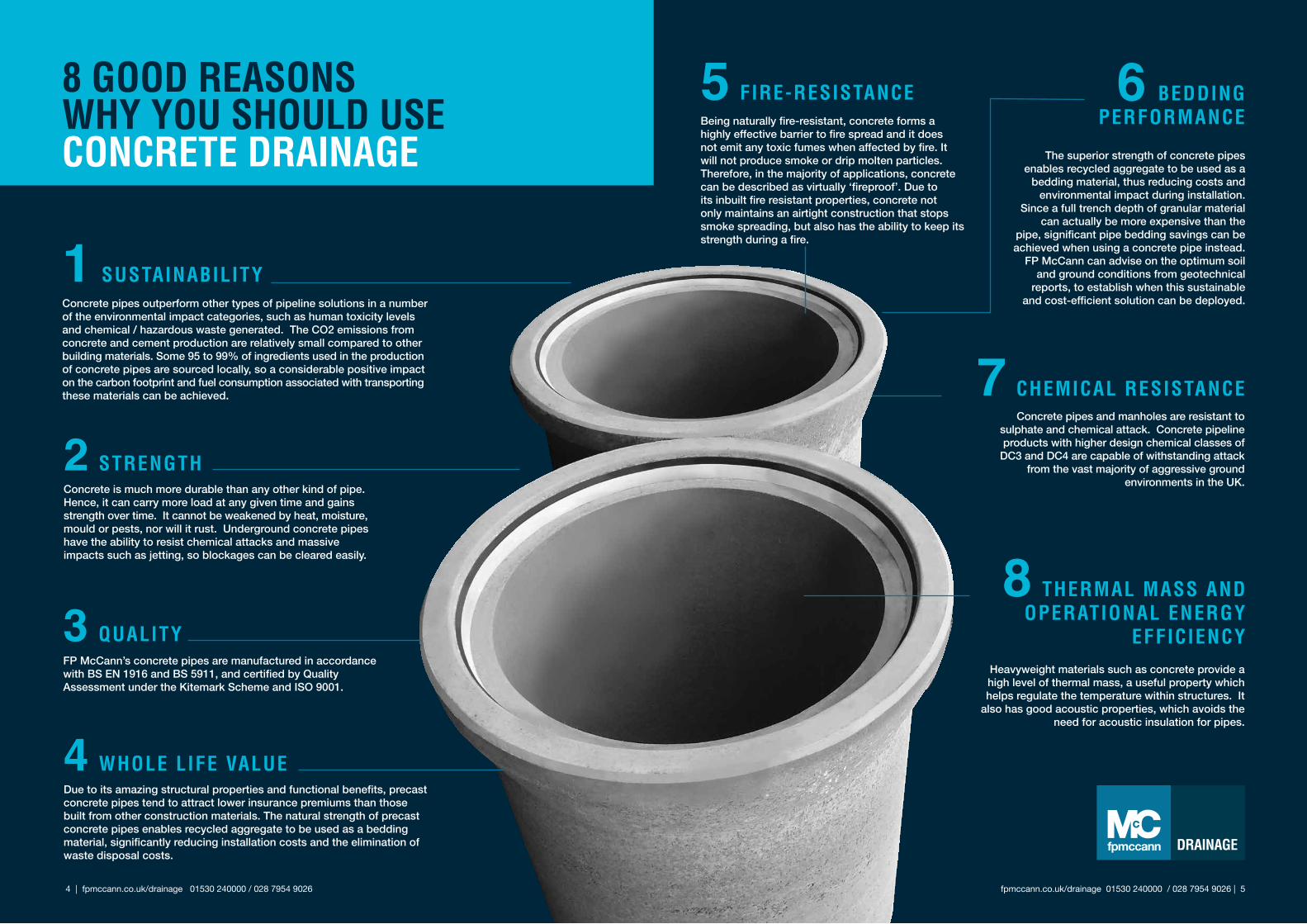
8 ThERMAl MAss AND opERATIoNAl ENERGy
EFFIcIENcyHeavyweight materials such as concrete provide a high level of thermal mass, a useful property which helps regulate the temperature within structures. It
also has good acoustic properties, which avoids the need for acoustic insulation for pipes.
6 bEDDING pERFoRMANcE
The superior strength of concrete pipes enables recycled aggregate to be used as a
bedding material, thus reducing costs and environmental impact during installation.
Since a full trench depth of granular material can actually be more expensive than the
pipe, significant pipe bedding savings can be achieved when using a concrete pipe instead.
FP McCann can advise on the optimum soil and ground conditions from geotechnical
reports, to establish when this sustainable and cost-efficient solution can be deployed.
7 chEMIcAl REsIsTANcEConcrete pipes and manholes are resistant to
sulphate and chemical attack. Concrete pipeline products with higher design chemical classes of
DC3 and DC4 are capable of withstanding attack from the vast majority of aggressive ground
environments in the UK.
5 FIRE-REsIsTANcEBeing naturally fire-resistant, concrete forms a highly effective barrier to fire spread and it does not emit any toxic fumes when affected by fire. It will not produce smoke or drip molten particles. Therefore, in the majority of applications, concrete can be described as virtually ‘fireproof’. Due to its inbuilt fire resistant properties, concrete not only maintains an airtight construction that stops smoke spreading, but also has the ability to keep its strength during a fire.
1 susTAINAbIlITyConcrete pipes outperform other types of pipeline solutions in a number of the environmental impact categories, such as human toxicity levels and chemical / hazardous waste generated. The CO2 emissions from concrete and cement production are relatively small compared to other building materials. Some 95 to 99% of ingredients used in the production of concrete pipes are sourced locally, so a considerable positive impact on the carbon footprint and fuel consumption associated with transporting these materials can be achieved.
2 sTRENGThConcrete is much more durable than any other kind of pipe. Hence, it can carry more load at any given time and gains strength over time. It cannot be weakened by heat, moisture, mould or pests, nor will it rust. Underground concrete pipes have the ability to resist chemical attacks and massive impacts such as jetting, so blockages can be cleared easily.
3 QuAlITyFP McCann’s concrete pipes are manufactured in accordance with BS EN 1916 and BS 5911, and certified by Quality Assessment under the Kitemark Scheme and ISO 9001.
4 WholE lIFE vAluEDue to its amazing structural properties and functional benefits, precast concrete pipes tend to attract lower insurance premiums than those built from other construction materials. The natural strength of precast concrete pipes enables recycled aggregate to be used as a bedding material, significantly reducing installation costs and the elimination of waste disposal costs.
8 GooD REAsoNs Why you shoulD usE coNcRETE DRAINAGE
fpmccann.co.uk/drainage 01530 240000 / 028 7954 9026 | 5 4 | fpmccann.co.uk/drainage 01530 240000 / 028 7954 9026
fpmccann.co.uk/drainage 01530 240000 / 028 7954 9026 | 7
* Lifting anchors available
6 | fpmccann.co.uk/drainage 01530 240000 / 028 7954 9026
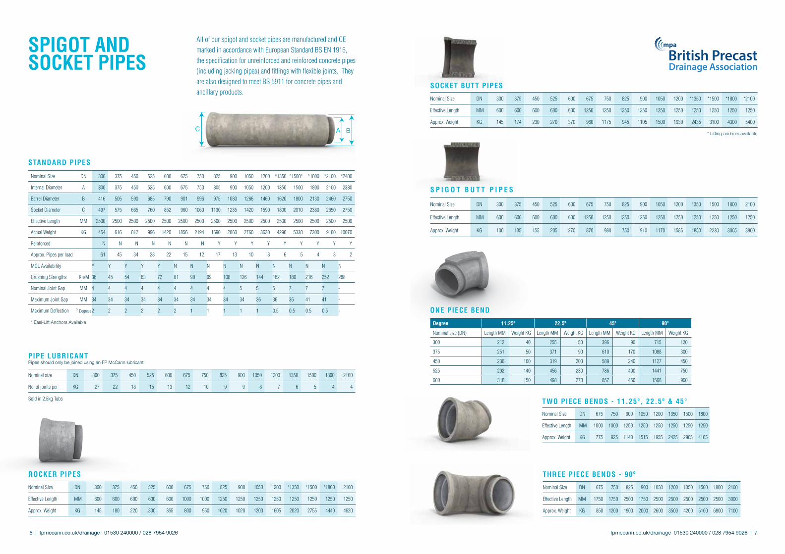
spIGoT AND sockET pIpEs
Sold in 2.5kg Tubs
C A B
sTANDARD pIpEs
All of our spigot and socket pipes are manufactured and CE marked in accordance with European Standard BS EN 1916, the specification for unreinforced and reinforced concrete pipes (including jacking pipes) and fittings with flexible joints. They are also designed to meet BS 5911 for concrete pipes and ancillary products.
pIpE lubRIcANT Pipes should only be joined using an FP McCann lubricant
Nominal size DN 300 375 450 525 600 675 750 825 900 1050 1200 1350 1500 1800 2100
No. of joints per KG 27 22 18 15 13 12 10 9 9 8 7 6 5 4 4
RockER pIpEs
Nominal Size DN 300 375 450 525 600 675 750 825 900 1050 1200 *1350 *1500 *1800 2100
Effective Length MM 600 600 600 600 600 1000 1000 1250 1250 1250 1250 1250 1250 1250 1250
Approx. Weight KG 145 180 220 300 365 800 950 1020 1020 1200 1605 2020 2755 4440 4620
s p I G o T b u T T p I p E s
Nominal Size DN 300 375 450 525 600 675 750 825 900 1050 1200 1350 1500 1800 2100
Effective Length MM 600 600 600 600 600 1250 1250 1250 1250 1250 1250 1250 1250 1250 1250
Approx. Weight KG 100 135 155 205 270 870 980 750 910 1170 1585 1850 2230 3005 3800
sockET buTT pIpEs
Nominal Size DN 300 375 450 525 600 675 750 825 900 1050 1200 *1350 *1500 *1800 *2100
Effective Length MM 600 600 600 600 600 1250 1250 1250 1250 1250 1250 1250 1250 1250 1250
Approx. Weight KG 145 174 230 270 370 960 1175 945 1105 1500 1930 2435 3100 4300 5400
oNE pIEcE bEND
ThREE pIEcE bENDs - 90º
Nominal Size DN 675 750 825 900 1050 1200 1350 1500 1800 2100
Effective Length MM 1750 1750 2500 1750 2500 2500 2500 2500 2500 3000
Approx. Weight KG 850 1200 1900 2000 2600 3500 4200 5100 6800 7100
TWo pIEcE bENDs - 11.25º, 22.5º & 45º
Nominal Size DN 675 750 900 1050 1200 1350 1500 1800
Effective Length MM 1000 1000 1250 1250 1250 1250 1250 1250
Approx. Weight KG 775 925 1140 1515 1955 2425 2965 4105
Degree 11.25º 22.5º 45º 90º
Nominal size (DN) Length MM Weight KG Length MM Weight KG Length MM Weight KG Length MM Weight KG
300 212 40 255 50 396 90 715 120
375 251 50 371 90 610 170 1088 300
450 236 100 319 200 589 240 1127 450
525 292 140 456 230 786 400 1441 750
600 318 150 498 270 857 450 1568 900
Nominal Size DN 300 375 450 525 600 675 750 825 900 1050 1200 *1350 *1500* *1800 *2100 *2400
Internal Diameter A 300 375 450 525 600 675 750 805 900 1050 1200 1350 1500 1800 2100 2380
Barrel Diameter B 416 505 590 685 790 901 996 975 1080 1266 1460 1620 1800 2130 2460 2750
Socket Diameter C 497 575 665 760 852 960 1060 1130 1235 1420 1590 1800 2010 2380 2650 2750
Effective Length MM 2500 2500 2500 2500 2500 2500 2500 2500 2500 2500 2500 2500 2500 2500 2500 2500
Actual Weight KG 454 616 812 996 1420 1856 2194 1690 2060 2760 3630 4290 5330 7300 9160 10070
Reinforced N N N N N N N Y Y Y Y Y Y Y Y Y
Approx. Pipes per load 61 45 34 28 22 15 12 17 13 10 8 6 5 4 3 2
MOL Availability Y Y Y Y Y N N N N N N N N N N N
Crushing Strengths Kn/M 36 45 54 63 72 81 90 99 108 126 144 162 180 216 252 288
Nominal Joint Gap MM 4 4 4 4 4 4 4 4 4 5 5 5 7 7 7 -
Maximum Joint Gap MM 34 34 34 34 34 34 34 34 34 34 36 36 36 41 41 -
Maximum Deflection ° Degrees2 2 2 2 2 2 1 1 1 1 1 0.5 0.5 0.5 0.5 -
* Easi-Lift Anchors Available
mpa
FpM Tools AuTocAD
All junctions are to be fitted on their side. Junctions are not designed for vertical surface compaction and need to be surrounded in concrete.
E
Fast-Fit Seal
Rigidrain Coupling
Rigidrain Bend
Fast-Fit Seal
Naylor Clay Bend
Ultra Rib Pipe
Fast-Fit Seal
Half U/R Connector
Ultra Rib Bend
SA10 Adaptor
160mm Polypipe
Bend
HepworthSupersleeve
Fast-Fit Seal
coNvERT To oThER pIpE TypEs
FAsTFIT JuNcTIoNs
Nominal Size DN 300 375 450 525 600 675 750 825 900 1050 1200 1350 1500 1800
Branch Size E 150 150 150 150 150 150 150 150 150 150 150 150 150 150
Effective Length mm 600 600 600 600 600 1000 1000 1250 1250 1250 1250 2500 2500 2500
Approx. Weight KG 132 169 211 277 350 750 905 800 1140 1513 2427 4416 5120 7360
DN
www.microdrainage.co.uk
Designed for AutoCAD, the FPM AutoCAD toolbar is a set of commands to aid civil engineers, quantity surveyors and estimators in producing quick and accurate drainage take-offs.
It provides tabular data for the drainage layout and specifies the relevant FP McCann Easi-Bases automatically.
The FPM AutoCad Tools toolbar is used to work through the drainage plan in sequence, specifying each manhole in turn. Manhole references, invert levels, cover levels, pipe types and pipe lengths are all recorded. When complete, a table is generated within the actual plan. This table can then be exported as a .csv file and opened in MS Excel or other similar supporting program.
The screenshot left shows the drainage table generated within AutoCAD and, below left, the exported Excel table ready for the quantity surveyor/buyer/estimator to send out for pricing.
From within AutoCAD, the Manhole edit tool can be used to assemble the manhole and pipe data at a particular manhole reference within the plan.
Subscribers to Micro Drainage’s WinDes 2013.1 sustainable drainage software can incorporate Easi-Base into quick and ac-curate drainage scheduling, in accordance with the Predl clock notation.
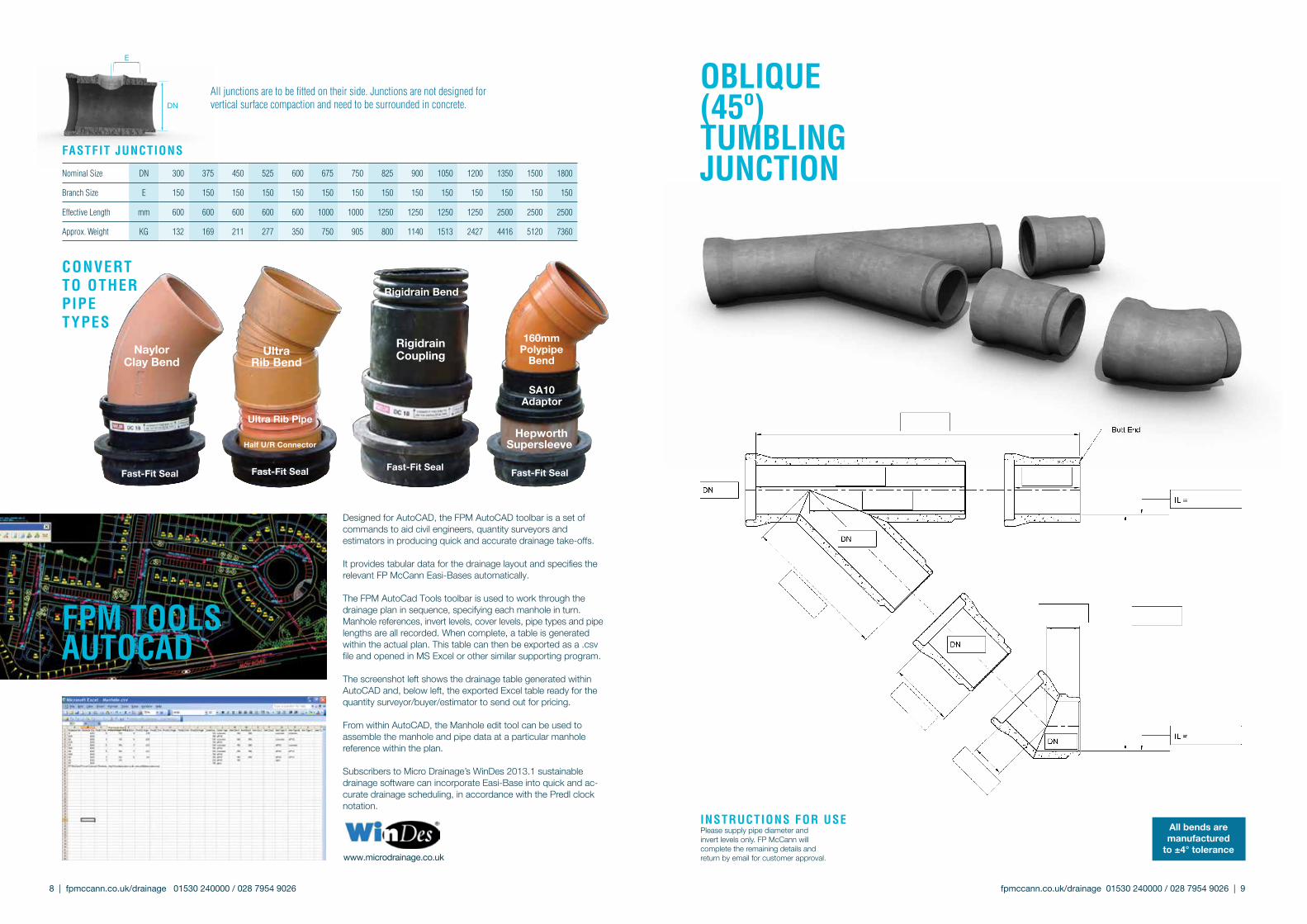
oblIQuE (45º) TuMblING JuNcTIoN
INsTRucTIoNs FoR usEPlease supply pipe diameter and invert levels only. FP McCann will complete the remaining details and return by email for customer approval.
All bends are manufactured
to ±4° tolerance
fpmccann.co.uk/drainage 01530 240000 / 028 7954 9026 | 9 8 | fpmccann.co.uk/drainage 01530 240000 / 028 7954 9026
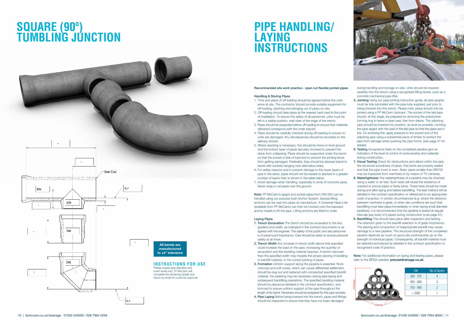
sQuARE (90º) TuMblING JuNcTIoN
INsTRucTIoNs FoR usEPlease supply pipe diameter and invert levels only. FP McCann will complete the remaining details and return by email for customer approval.
All bends are manufactured
to ±4° tolerance
Recommended site work practice - open cut flexible jointed pipes
Handling & Storing Pipes1. Time and place of off-loading should be agreed before the units arrive at site. The contractor should provide suitable equipment for off-loading, stacking and stringing out of pipes on-site.2. Off-loading should take place at the nearest hard road to the point
of installation. To ensure the safety of all personnel, units must be left in a stable position, well clear of the edge of the trench.
3. Pipes should be inspected before off-loading to ensure that materials delivered correspond with the order placed.4. Pipes should be carefully checked during off-loading to ensure no
units are damaged. Any discrepancies should be recorded on the delivery docket.
5. Where stacking is necessary, this should be done on level ground and the bottom layer of pipes securely chocked to prevent the stack from collapsing. Pipes should be supported under the barrel so that the socket is free of load and to prevent the jointing faces from getting damaged. Preferably, they should be stacked barrel to barrel with sockets hanging over alternative sides.
6. For safety reasons and to prevent damage to the lower layers of pipe in the stack, pipes should not be loaded or stacked in a greater number of layers than is shown in the table below.
7. Avoid damage when handling, especially to ends of concrete pipes. Never drag or roll pipes over the ground.
Note: FP McCann’s spigot and socket pipes from DN1350 can be handled using our purpose-built Anchor System. Special lifting anchors can be cast into pipes at manufacture. A Universal Head Link (available from FP McCann) can then be hooked onto the exposed anchor heads to lift the pipe. Lifting anchors are fitted to order.
Laying Pipes1. Trench Excavation The trench should be excavated to the line,
gradient and width, as indicated in the contract documents or as agreed with the engineer. The safety of the public and site personnel is of paramount importance. Care should be taken to ensure personal safety at all times.
2. Trench Width Any increase in trench width above that specified could increase the load on the pipe, increasing the quantity of excavation and the bedding material required. A trench narrower than the specified width may impede the proper placing of bedding or backfill material, or the correct jointing of pipes.
3. Formation Uniform support along the pipeline is essential. Rock outcrops and soft zones, which can cause differential settlement, should be dug out and replaced with compacted specified backfill material. De-watering may be necessary during pipe laying and subsequent backfilling operations. The specified bedding material
should be placed as detailed in the contract specification, and trimmed to ensure uniform support of the pipe throughout the length of its barrel. Recesses should be prepared for the pipe sockets.4. Pipe Laying Before being lowered into the trench, pipes and fittings
should be inspected to ensure that they have not been damaged
during handling and storage on-site. Units should be lowered carefully into the trench using a recognised lifting tackle, such as a concrete mechanical pipe lifter.5. Jointing Using our pipe jointing instruction guide, all pipe spigots
must be fully lubricated with the pipe lube supplied, just prior to being lowered into the trench. Please note: pipes should only be jointed using a FP McCann lubricant. The socket of the laid pipe should, at this stage, be prepared by removing the polystyrene forming ring to leave a clean seal, free from debris. The adjoining pipe should be lowered into position, as level as possible, centring the pipe spigot with the seal of the laid pipe so that the pipes are in line. On achieving this, apply pressure to the socket end of the
adjoining pipe using a substantial piece of timber to protect the pipe from damage when pushing the pipe home. (see page 47 for details)6. Testing Acceptance tests on the completed pipeline give an indication of the level of control of workmanship and materials during construction.7. Visual Testing Check for obstructions and debris within the pipe,
the structural soundness of pipes, that joints are properly sealed and that the pipe invert is even. Note: pipes smaller than DN750 may be inspected from manholes or by means of TV cameras.
8. Watertightness The watertightness of a pipeline may be checked using a water or air test. Such tests will reveal the existence of cracked or porous pipes or faulty joints. These tests should be made during and after laying and before backfilling. The test method will be detailed in the contract specification or referenced to an appropriate code of practice. In certain circumstances (e.g. where the distance between manholes is great, or when site conditions are such that
backfilling must take place immediately or when laying small diameter pipelines), it is recommended that the pipeline is tested at regular intervals (say every 2/3 pipes) during construction (s ee page 47).9. Backfilling This should take place after inspection and testing.
The attention given to the backfill selection is of great importance. The placing and compaction of inappropriate backfill may cause damage to a new pipeline. The structural strength of the completed pipeline depends as much on good site workmanship as on the strength of individual pipes. Consequently, all backfill material must be selected and placed as detailed in the contract specification or recognised code of practice.
Note: For additional information on laying and testing pipes, please refer to the BPDA website: precastdrainage.co.uk
2.0
M M
ax
Chocks
pIpE hANDlING/ lAyING INsTRucTIoNs
DN No of layers
300 - 375 4
450 - 600 3
750 - 900 2
> 1050 1
fpmccann.co.uk/drainage 01530 240000 / 028 7954 9026 | 11 10 | fpmccann.co.uk/drainage 01530 240000 / 028 7964 2558
A. B.
A.
C.B.
A.
B.C.
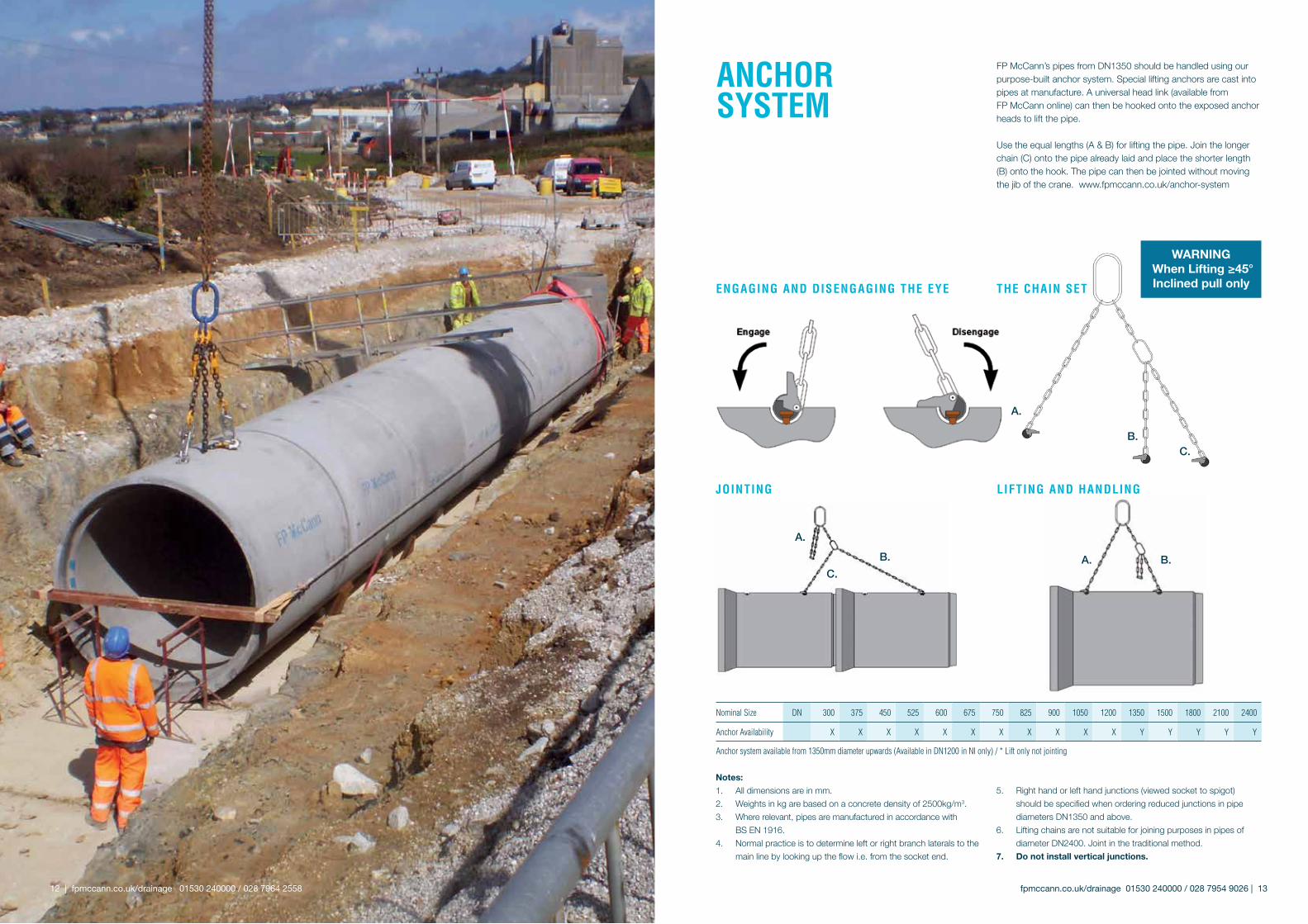
ENGAGING AND DIsENGAGING ThE EyE
Anchor system available from 1350mm diameter upwards (Available in DN1200 in NI only) / * Lift only not jointing
WARNING When Lifting ≥45°Inclined pull onlyThE chAIN sET
JoINTING lIFTING AND hANDlING
Notes:1. All dimensions are in mm.2. Weights in kg are based on a concrete density of 2500kg/m3.3. Where relevant, pipes are manufactured in accordance with
BS EN 1916.4. Normal practice is to determine left or right branch laterals to the
main line by looking up the flow i.e. from the socket end.
5. Right hand or left hand junctions (viewed socket to spigot) should be specified when ordering reduced junctions in pipe diameters DN1350 and above.
6. Lifting chains are not suitable for joining purposes in pipes of diameter DN2400. Joint in the traditional method.
7. Do not install vertical junctions.
FP McCann’s pipes from DN1350 should be handled using our purpose-built anchor system. Special lifting anchors are cast into pipes at manufacture. A universal head link (available from FP McCann online) can then be hooked onto the exposed anchor heads to lift the pipe.
Use the equal lengths (A & B) for lifting the pipe. Join the longer chain (C) onto the pipe already laid and place the shorter length (B) onto the hook. The pipe can then be jointed without moving the jib of the crane. www.fpmccann.co.uk/anchor-system
ANchoRsysTEM
Nominal Size DN 300 375 450 525 600 675 750 825 900 1050 1200 1350 1500 1800 2100 2400
Anchor Availability X X X X X X X X X X X Y Y Y Y Y
fpmccann.co.uk/drainage 01530 240000 / 028 7954 9026 | 13 12 | fpmccann.co.uk/drainage 01530 240000 / 028 7964 2558
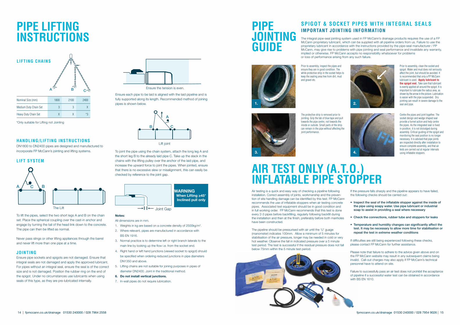
hANDlING/lIFTING INsTRucTIoNsDN1800 to DN2400 pipes are designed and manufactured to incorporate FP McCann’s jointing and lifting systems.
lIFT sysTEM
To lift the pipes, select the two short legs A and B on the chain set. Place the spherical coupling over the cast-in anchor and engage by turning the tail of the head link down to the concrete. The pipe can then be lifted as normal.
Never pass slings or other lifting appliances through the barrel and never lift more than one pipe at a time.
JoINTINGEnsure pipe sockets and spigots are not damaged. Ensure that integral seals are not damaged and apply the approved lubricant. For pipes without an integral seal, ensure the seal is of the correct size and is not damaged. Position the rubber ring on the end of the spigot. Under no circumstances use lubricants when using seals of this type, as they are pre-lubricated internally.
Ensure each pipe to be laid is aligned with the laid pipeline and is fully supported along its length. Recommended method of joining pipes is shown below.
To joint the pipe using the chain system, attach the long leg A and the short leg B to the already laid pipe C. Take up the slack in the chains with the lifting pulley over the anchor of the laid pipe, and increase the upward force to joint the pipes. When jointed, ensure that there is no excessive slew or misalignment, this can easily be checked by reference to the joint gap.
Notes:All dimensions are in mm.1. Weights in kg are based on a concrete density of 2500kg/m3.2. Where relevant, pipes are manufactured in accordance with
BS EN 1916.3. Normal practice is to determine left or right branch laterals to the
main line by looking up the flow i.e. from the socket end.4. Right hand or left hand junctions (viewed socket to spigot) should
be specified when ordering reduced junctions in pipe diameters DN1350 and above.
5. Lifting chains are not suitable for joining purposes in pipes of diameter DN2400. Joint in the traditional method.
6. Do not install vertical junctions. 7. In-wall pipes do not require lubrication.
Ensure the tension is even.
Lift joint
A BC
The Lift
A
B C
Joint Gap
WARNINGWhen Lifting ≥45°Inclined pull only
lIFTING chAINs
A B C
*Only suitable for Lifting not Jointing
pIpE lIFTINGINsTRucTIoNs
Nominal Size (mm) 1800 2100 2400
Medium Duty Chain Set 3 3 X
Heavy Duty Chain Set X X *3 Centre the pipes and joint together. The socket design and wedge shaped seal provide a funnel action and help centre the pipes. As the integrated seal is fixed in position, it is not dislodged during assembly. Critical guiding of the spigot and monitoring the seal position is no longer necessary. It is advised that pipe joints are inspected directly after installation to ensure complete assembly, and that air tests are carried out at regular intervals using inflatable stoppers.
Prior to assembly, inspect the pipes and ensure they are in good condition. The white protective strip in the socket helps to keep the sealing area free from dirt, mud and gravel etc.
4.
1. 2.
Prior to assembly, clean the socket and spigot. Water and mud does not seriously affect the joint, but should be avoided. It is recommended that only a FP McCann lubricant is used. Apply lubricant to the spigot end. Take care that lubricant is evenly applied all around the spigot. It is important to lubricate the radius area, as shown by the arrow in the picture. Lubrication is easier with the pipe suspended. Dry jointing can result in severe damage to the seal and pipe.
The protective strip is removed prior to jointing. Grip the tab of blue tape and pull towards the pipe centre, not towards the inside or outside. Small parts of the strip can remain in the pipe without affecting the joint performance.
spIGoT & sockET pIpEs WITh INTEGRAl sEAlsIMpoRTANT JoINTING INFoRMATIoN
The integral pipe-seal jointing system used in FP McCann’s drainage products requires the use of a FP McCann proprietary lubricant, which can be supplied with all pipeline orders from us. Failure to use the proprietary lubricant in accordance with the instructions provided by the pipe-seal manufacturer / FP McCann, may give rise to problems with pipe jointing and seal performance and invalidate any warranty, implied or otherwise. FP McCann accepts no responsibility whatsoever for problems or loss of performance arising from any such failure.
pIpE JoINTING GuIDE
3.
AIR TEsT oNly (A.T.o.) INFlATAblE pIpE sToppERAir testing is a quick and easy way of checking a pipeline following installation. Correct assembly of joints, workmanship and the preven-tion of site handling damage can be identified by this test. FP McCann recommends the use of inflatable stoppers when air testing concrete pipes. Associated test equipment should be in good condition and in full working order. FP McCann recommends that this test is done every 2-3 pipes before backfilling, regularly following backfill during the installation and then at the finish; preferably before both manholes have been constructed. The pipeline should be pressurised with air until the ‘U’ guage (manometer) indicates 100mm. Allow a minimum of 5 minutes for stabilisation of the air pressure, longer may be needed in cold or very hot weather. Observe the fall in indicated pressure over a 5 minute test period. The test is successful if the residual pressure does not fall below 75mm within the 5 minute test period.
If the pressure falls sharply and the pipeline appears to have failed, the following checks should be carried out: • Inspect the seal of the inflatable stopper against the inside of the pipe using soapy water. Use pipe lubricant or industrial soap to assist in providing a seal where necessary • Check the connections, rubber tube and stoppers for leaks • Temperature and humidity changes can significantly affect the test. It may be necessary to allow more time for stabilisation or repeat the test in extreme weather conditions If difficulties are still being experienced following these checks, please contact FP McCann for further assistance. Please note that failure to adhere to the advice given above and on the FP McCann website may result in any subsequent claims being invalid. Call-out charges may also apply if FP McCann’s technical personnel have to attend on site.
Failure to successfully pass an air test does not prohibit the acceptance of pipeline if a successful water test can be obtained in accordance with BS EN 1610.
fpmccann.co.uk/drainage 01530 240000 / 028 7954 9026 | 15 14 | fpmccann.co.uk/drainage 01530 240000 / 028 7964 2558
Note: All junctions are to be fitted on their side. Junctions are not designed for vertical surface compaction.
Under no circumstances should lubricants be used when assembling pre-lubricated pipes; the seal is lubricated internally.
NB: Dimensions above are in mm.
Fastfits available 150mm Super sleeve made to order. Can connect to other pipes via additional adaptors not supplied
pRE-lubRIcATED pIpEs
sTANDARD pIpEs
Nominal Size DN 1800 2100 2400
Internal Diameter A 1830 2076 2380
Barrel Diameter B 2140 2410 2750
Effective Length C 2500 2500 2500
Approx. Weight KG 6525 7960 10070
Pipes per Load Qty 4 3 2
RIGhT ANGlE (90°) REDucED JuNcTIoN
Nominal Size A 1800 2100 2400
Branch Supersleeve B 100 100 100
Branch Supersleeve B 150 150 150
Effective Length C 2500 2500 2500
Approx. Weight KG 6525 7960 10070
spIGoTT/sockET buTT pIpEs
Nominal Size DN 1800 2100 2400
Internal Diameter A 1830 2076 2380
Barrel Diameter B 2140 2410 2750
Effective Length C 1250 1250 1250
Approx. Weight KG 3370 4095 5195
RockER pIpEs
Nominal Size DN 1800 2100 2400
Internal Diameter A 1830 2076 2380
Barrel Diameter B 2140 2410 2750
Effective Length C 1250 1250 1250
Approx. Weight KG 3310 4010 5040
Nominal Size A 1800 2100 2400
Branch Supersleve B 100 100 100
Effective Length C 2500 2500 2500
Approx. Weight KG 6525 7960 10070
spIGoT buTT pIpEs
Nominal Size DN 1800 2100 2400
Internal Diameter A 1830 2076 2380
Barrel Diameter B 2140 2410 2750
Effective Length C 1250 1250 1250
Approx. Weight KG 3020 3610 4670
TWo pIEcE bENDs
Nominal Size DN 1800 2100 2400
Internal Diameter A 1830 2076 2380
Angle غ 11.25 3 3 3
Angle غ 22.5 3 3 3
Angle غ 45 3 3 3
oblIQuE (45°) REDucED JuNcTIoN
Nominal size (A) (DN)
(mm)
Available Depth of section (D) WallThickness
(c)mm
litres per
metre
barrel Diam-eter (b)
mm
Approx Weight kg. (per metre)
Approx. products per load
Qty. (metre)
lifting holeQty/Dia.
(per /unit)(mm)
250mm(±25mm)
500mm(±25mm)
750mm(±50mm)
1000mm(±50mm)
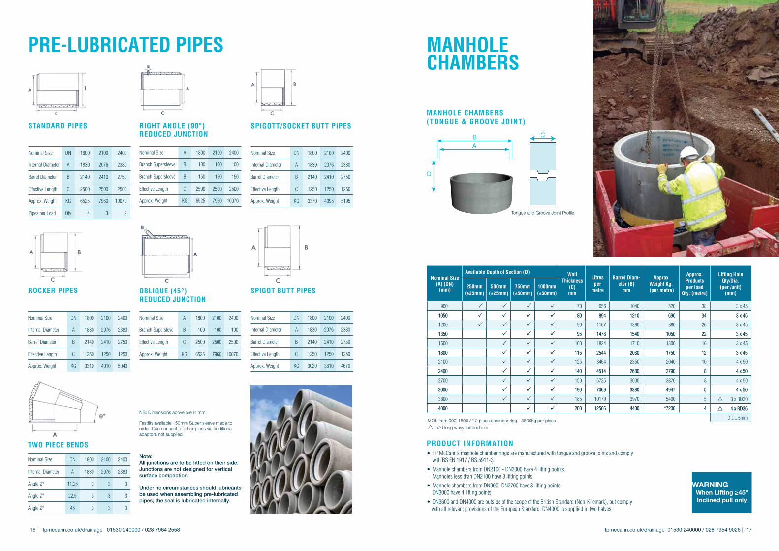
900 P P P P 70 656 1040 520 38 3 x 45
1050 P P P P 80 894 1210 690 34 3 x 45
1200 P P P P 90 1167 1380 880 26 3 x 45
1350 P P P 95 1478 1540 1050 22 3 x 45
1500 P P P 100 1824 1710 1300 16 3 x 45
1800 P P P 115 2544 2030 1750 12 3 x 45
2100 P P P 125 3464 2350 2040 10 4 x 50
2400 P P P 140 4514 2680 2790 8 4 x 50
2700 P P P 150 5725 3000 3370 8 4 x 50
3000 P P P 190 7069 3380 4947 5 4 x 50
3600 P P P 185 10179 3970 5400 5 r 3 x RD30
4000 P P 200 12566 4400 *7200 4 r 4 x RD36
Dia ± 5mm
MANholE chAMbERs (ToNGuE & GRoovE JoINT)
AB
D
C
Tongue and Groove Joint Profile
pRoDucT INFoRMATIoN• FP McCann’s manhole chamber rings are manufactured with tongue and groove joints and comply with BS EN 1917 / BS 5911-3
• Manhole chambers from DN2100 - DN3000 have 4 lifting points. Manholes less than DN2100 have 3 lifting points
• Manhole chambers from DN900 -DN2700 have 3 lifting points. DN3000 have 4 lifting points
• DN3600 and DN4000 are outside of the scope of the British Standard (Non-Kitemark), but comply with all relevant provisions of the European Standard. DN4000 is supplied in two halves
WARNINGWhen Lifting ≥45°Inclined pull only
MANholEchAMbERs
MOL from 900-1500 / * 2 piece chamber ring - 3600kg per piecer 570 long wavy tail anchors
fpmccann.co.uk/drainage 01530 240000 / 028 7954 9026 | 17 16 | fpmccann.co.uk/drainage 01530 240000 / 028 7964 2558
Nominal size (A) (DN)
(mm)
Available Depth of section (D) WallThickness
(c)mm
litres per
metre
barrel Diam-eter (b)
mm
Approx Weight kg. (per metre)
Approx. products per load
Qty. (metre)
lifting holeQty/Dia.
(per /unit)(mm)
250mm(±25mm)
500mm(±25mm)
750mm(±50mm)
1000mm(±50mm)
900 P P P P 70 656 1040 520 38 3 x 45
1050 P P P P 80 894 1210 690 34 3 x 45
1200 P P P P 90 1167 1380 880 26 3 x 45
1350 P P P 95 1478 1540 1050 22 3 x 45
1500 P P P 100 1824 1710 1300 16 3 x 45
1800 P P P 115 2544 2030 1750 12 3 x 45
2100 P P P 125 3464 2350 2040 10 4 x 50
2400 P P P 140 4514 2680 2790 8 4 x 50
2700 P P P 150 5725 3000 3370 8 4 x 50
3000 P P P 190 7069 3380 4947 5 4 x 50
3600 P P P 185 10179 3970 5400 5 r 3 x RD30
4000 P P 200 12566 4400 *7200 4 r 4 x RD36
Dia ± 5mm
REcoMMENDED sITE WoRk pRAcTIcE - MANholE chAMbERsREcoMMENDED lIFTING EQuIpMENT
Nominal size DN (mm)
lifting holeQty/dia(p/unit)
36mmlifting pin3.5 t sWl
42mmlifting pin3.5 t sWl
3 leg lifting chain
3.1t
4 leg lifting chain sWl 6.7 t
900 3 x 45mm dia P P1050 3 x 45mm dia P P1200 3 x 45mm dia P P1350 3 x 45mm dia P P1500 3 x 45mm dia P P1800 3 x 45mm dia P P2100 4 x 50mm dia P P2400 4 x 50mm dia P P2700 4 x 50mm dia P P3000 4 x 50mm dia P P3600 3 x RD30 (Loops) P4000 4 x RD36 (Loops) P
Dia + 5mm
MANholEsoAkAWAys
Please note this is a guideline based on sealant supplied by FP McCann only.
Nominal size DN (MM)
sealant size (metres)
No. of rolls p/joint (metres)
Rolls required Quantity
900 20 x 20 x 4 0.88 11050 20 x 20 x 4 1.00 11200 20 x 40 x 4 1.13 21350 20 x 40 x 4 1.25 21500 20 x 40 x 4 1.38 21800 20 x 40 x 4 1.63 22100 20 x 40 x 4 1.88 22400 20 x 40 x 4 2.13 32700 20 x 40 x 4 2.38 33000 12 x 120 x 6 1.75 23600 12 x 120 x 6 2.08 34000 12 x 120 x 6 2.33 3
sEAlING sTRIp
MANholE soAkAWAy chAMbERs
* DN3600/4000 see Manhole Chambers / DN3600/4000 Manhole Soakaways made to order
Nominal size
DN (mm)
No. of 75mm holes per chamber
WallThick-nessmm
litresper
metre ring
barrel Dia.mm
Approx Weight
kg. (p/metre)
Approx. products per load
Qty. (metre)
500mm
750mm
1000mm
900 5 8 10 70 656 1040 520 461050 6 9 12 80 894 1210 690 341200 7 10 14 90 1167 1380 880 261350 8 11 15 95 1478 1540 1050 221500 8 13 17 100 1824 1710 1300 181800 10 15 20 115 2544 2030 1750 122100 12 18 24 125 3464 2350 2040 102400 14 20 27 140 4514 2680 2790 82700 15 23 31 150 5725 3000 3370 63000 17 25 34 190 7069 3380 4947 5
*3600 20 31 41 185 10179 3970 5400 5*4000 23 34 45 200 12566 4400 6800 1.5
coNsTRucTIoNTo ensure that the manhole structure is vertical, accurate levelling of the formation or the in-situ concrete foundation is essential. Please note: the depths of each manhole can vary and are subject to tolerances; it is recommended that each unit installed has it’s depth measured prior to installation, to ascertain if the levelling requirements are satisfactorily met. Tongue and groove joints should be installed with the groove facing upward. Manhole sections fitted with double steps can be used at any depth. However, it is recommended that the deepest section of manhole units should be used whenever possible, in order to minimise the number of joints and costs. Precast cover slabs can be laid directly onto the shaft or chamber rings. To allow for any differential settlement between manhole and pipeline, a flexible joint incorporating short length rocker pipes should be constructed as close as possible to the outside of the manhole or the concrete surround, if used. Extra care must be taken to ensure that joints are properly made.
JoINTINGPrecast manhole components are provided with joints formed within the wall section. These are sealed with cement and sand mortar, or with proprietary FP McCann mastic sealants. Precast concrete manhole units, well jointed, provide an adequate seal under normal conditions.
REINsTATEMENTAn in-situ concrete surround to precast concrete manholes is not necessary because a well-constructed precast manhole is a strong, durable structure with its own inherent strength and would only require a surround for exceptional structural reasons. However, under some specifications, a concrete surround is required where the depth from ground level to the base of the concrete chamber ring exceeds 4.5m. In this case, the surround should be of 150mm thickness. Backfilling should take place as each precast manhole section is placed. It must be brought up evenly and compacted around the manhole to prevent displacement.
TEsTINGIt is generally unnecessary to apply water tests to manholes. In normal working conditions, manholes are not normally full of water. Prevention of infiltration is of more relevance than exfiltration. If infiltration does occur, it can be seen and remedied by sealing using an appropriate method.
Note: When handling precast products on site, it is recommended that the contractor has the correct lifting equipment in place and adheres to the relevant lifting guidelines and standards. Refer to the BPDA website for further information: precastdrainage.co.uk
hANDlING & INsTAllING MANholEs1. Time and place of off-loading should be agreed before the units arrive at
site. The contractor should provide suitable equipment for off-loading. For safety reasons, all chamber sections are loaded and delivered chimney fashion.
2. Off-loading should take place at the nearest hard road to the point of installation. When off-loaded, units should never be stored on their side (on the roll) but always be laid in the ‘as installed’ upright position.
3. Carefully inspect units during off-loading to verify that products are undamaged and comply with order placed. Note any discrepancies on the delivery docket and advise accordingly.
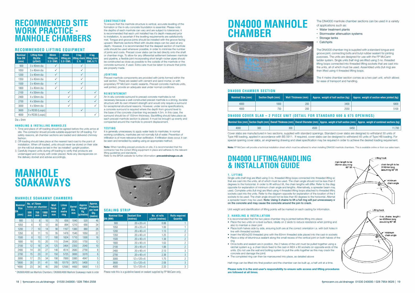
The DN4000 manhole chamber sections can be used in a variety of applications such as:• Water treatment plants• Stormwaterattenuationsystems• Storagetanks• Catchpits
The DN4000 chamber ring is supplied with a standard tongue and groove joint, connecting bolts and butyl rubber sealant for jointing purposes. The units are designed for use with the FP McCann ladder system. Single units (half ring) are lifted using 3 no. threaded lifting loops connected into threaded lifting sockets that are cast into the units, all of which must be used. Assembled units (full ring) are then lifted using 4 threaded lifting loops.
The 4 metre chamber section comes as a two part unit, which allows for ease of transport and handling.
DN4000 MANholEchAMbER
Nominal size (mm) section Depth (mm) Wall Thickness (mm) Approx. weight of half section (kg) Approx. weight of section when jointed (kg)
4000 1000 200 3400 6800
4000 750 200 2550 5100
DN4000 chAMbER sEcTIoN
Nominal size (mm) section Depth (mm) overall Thickness (mm) overall Diameter (mm) Approx. weight of half section (mm) Approx. weight of combined sections (kg)
4000 300 300 4500 6450 11,700
DN4000 covER slAb – 2 pIEcE uNIT (DETAIl FoR sTANDARD 600 & 675 opENINGs)
Cover slabs are manufactured in two sections, supplied with standard openings. Standard cover slabs are designed to withstand 30 units of Type HB loading, applied in accordance with BS 5911. If required, cover slabs can be designed to withstand 45 units of Type HB loading. For special opening cover slabs, an engineering drawing and steel specification may be required in order to achieve the desired loading requirement.
Note: FP McCann will provide a technical installation sheet which must be adhered to when installing DN4000 manhole chambers. This is available online or from our sales team.
1. lIFTINGSingle units (half ring) are lifted using 3 no. threaded lifting loops connected into threaded lifting sockets that are cast into the units, all of which must be used. The chain angle should not be less than 60 degrees to the horizontal. In order to lift without tilt, the chain lengths will differ. Refer to the diagram opposite for explanation of minimum chain angle and lengths. Alternatively, a spreader beam may be used. Complete units (full ring) are lifted using 4 threaded lifting loops attached to threaded lifting sockets cast into the units. Refer to the diagram opposite for explanation of the location of the lifting sockets to be used. The chain angle should not be less than 60 degrees to the horizontal. Alternatively, a spreader beam may be used. Note: Using 3 chains to lift a full ring will put unnecessary stress on the concrete and may cause the concrete around the join to crack.
Unit weight and identification of lifting points will be marked on each casting for information.
2. hANDlING & INsTAllATIoNIt is recommended that the two piece chamber ring is jointed before lifting into place:• Place the two units on a level surface, ideally on 2 skids to reduce resistance when jointing and
also to maintain a clean joint• Place both halves side by side, ensuring both are at the correct orientation i.e. with bolt holes in
line with threaded sockets• Insert the M24x200 threaded pins with the 60mm threaded side placed into the cast-in sockets • Place a strip of bituminous sealant along the small recess of the vertical joint on both halves of the
ring • Once bolts and sealant are in position, the 2 halves of the unit must be pulled together using a
ratchet system e.g. a chain block fixed to the cast-in M24 x 80 sockets on opposite ends of the units. (Do not use the wall end bolting system to pull the units together as this may crack the concrete and damage the joint)
• The completed ring can then be manoeuvred into place, as detailed above
Half-rings can be lifted into final position and the chamber can be built up, a half unit at a time.
Please note it is the end-user’s responsibility to ensure safe access and lifting procedures are followed at all times.
DN4000 lIFTING/hANDlING & INsTAllATIoN GuIDE
fpmccann.co.uk/drainage 01530 240000 / 028 7954 9026 | 19 18 | fpmccann.co.uk/drainage 01530 240000 / 028 7964 2558

FP McCann’s DN1200 Easi-Base is a prefabricated manhole base unit with integral benching, channels and connectors, that provides an immediate and long-lasting watertight solution in the management of waste water.
pRoDucT bENEFITs
• An extremely fast, efficient and economical method of constructing man-hole bases on-site
• Accepted by main UK Water Authorities
• Significant health and safety benefits
• An immediate watertight structure, allowing other trades to instantly follow on
• Factory prefabrication provides a quality finish to channelling and benching, and enables accurate combinations and variations for entry/exit pipes
• Connects with any type of pipe and is compatible with the DN1200 130mm thick wide wall chamber ring
• Maintenance of channels and benches are aided by clean access for inspection
• Eliminates the risk of water pollution that is associated with traditional methods of manhole construction, such as concrete base formation integ-rity failures due to bad weather conditions, which results in groundwater being contaminated with polluted raw sewerage and clean groundwater infiltrating the already overloaded raw sewerage system of pipelines and treatment plants
• The 7th Edition of Sewers for adoption has now been published to include precast bases; Easi-bases are in full accordance with the guidance provided.
• An 80 year guaranteed base
DN1200 EAsI-bAsE™
fpmccann.co.uk/drainage 01530 240000 / 028 7954 9026 | 21 20 | fpmccann.co.uk/drainage 01530 240000 / 028 7964 2558
DETAIl oF MANholE coNsTRucTIoN
Rocker PipeSpigot Butt
Flow
Base Chamber
Reducing Slab
2x Chamber Sections
Rocker Pipe
cuT AWAy DETAIl
Flow
Manhole Cover
2x Adjusting units
Cover slab
Shaft Section
MANholEcoNsTRucTIoN
The unique DN1200 Easi-Base utilises a polypropylene liner with prefabricated benching and channels. Pipe connection bells are pushed into the inlet and outlet points and the liner is then encased and embedded in concrete to provide its structural strength and integrity. The DN1200 Easi-Base is manufactured as a monolithic precast unit; it utilises the standard manhole tongue and groove joint and is ready for immediate use, in combination with either a standard 90mm thick manhole chamber or the new 130mm thick wide wall chamber ring.
The Easi-Base system connects with most type of pipe including Single wall uPVC, Twin wall, Concrete and Clay.
The DN1200 unit allows connection to channel diameters DN150 - DN300. FP McCann has developed a selection of adaptors to increase the range of pipe types accommodated.
Invert Height
520m
m -
670m
m
1200mm150mm
160mm 150mm
5°IN OUT
5°
10%
1%
sMAll/MEDIuM/lARGE EAsI-bAsE chAMbERs
Easi Base Diameter
Internal Channel Diameter
Invert Level(for take off)
Easi-Base Height
Easi-Base Weight
(Tonnes)
DN1200 150 370 520 2.2
DN1200 200 420 570 2.2
DN1200 225 470 620 3.5
DN1200 250 470 620 3.5
DN1200 300 520 670 3.5
pRoDucT FEATuREs
• The DN1200 Easi-Base is made to an internal diameter of 1200mm with a tongue and groove joint profile to match standard DN1200 manhole chamber rings
• Wall thickness is 150mm
• The base has a 150mm floor thickness with the outlet invert at approximately 150mm from ground level
• A 1% fall exists across the channel toward the outlet (1:100)
• A gradient of 1:10 is present at the benching with the run-off toward the channel
• The height of the DN1200 Easi-Base unit varies in accordance with the diameter of the main channel running through the unit. (Please refer to the above table for heights)
Socket Butt Pipe
All sizes are in mm
MEDIuM / lARGE EAsI-bAsE chAMbER sIZEs
Easi Base Diameter
Internal Channel Diameter
Invert Level(for take off)
Finished Height
Base Unit
Easi-Base Weight Tonnes
DN1500 150 470 750 3.5
DN1500 225 545 750 3.5
DN1500 300 600 750 3.5
DN1500 375 705 1000 4.6
DN1500 450 810 1000 4.4
DN1500 525 920 1250 4.7
DN1500 600 1000 1250 4.75
DN1800 150 470 750 6
DN1800 225 545 750 6
DN1800 300 600 750 6
DN1800 375 705 1000 6.5
DN1800 450 810 1000 6.5
DN1800 525 920 1250 7
DN1800 600 1000 1250 6.5
DN1800 675 1150 1400 8
DN1800 750 1200 1500 7.75
DN1800 825 1300 1500 7.5
DN1800 900 1300 1500 6.75
*DN2100 150 - 1200 1900 2436 r10.5
DN2400 Starter base, no benching
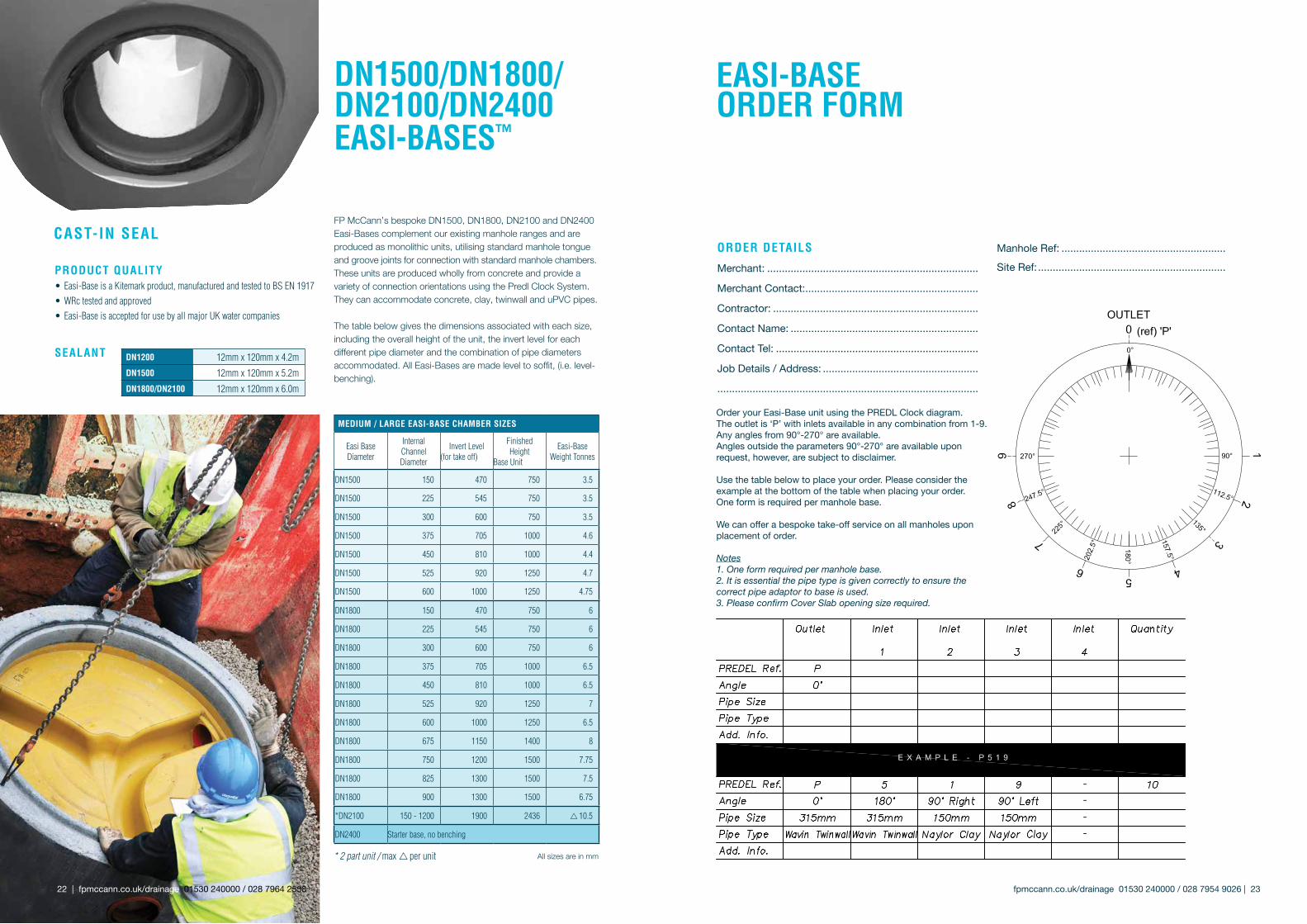
FP McCann’s bespoke DN1500, DN1800, DN2100 and DN2400 Easi-Bases complement our existing manhole ranges and are produced as monolithic units, utilising standard manhole tongue and groove joints for connection with standard manhole chambers. These units are produced wholly from concrete and provide a variety of connection orientations using the Predl Clock System. They can accommodate concrete, clay, twinwall and uPVC pipes.
The table below gives the dimensions associated with each size, including the overall height of the unit, the invert level for each different pipe diameter and the combination of pipe diameters accommodated. All Easi-Bases are made level to soffit, (i.e. level-benching).
DN1500/DN1800/DN2100/DN2400 EAsI-bAsEs™
fpmccann.co.uk/drainage 01530 240000 / 028 7954 9026 | 23 22 | fpmccann.co.uk/drainage 01530 240000 / 028 7964 2558
sEAlANT DN1200 12mm x 120mm x 4.2m
DN1500 12mm x 120mm x 5.2m
DN1800/DN2100 12mm x 120mm x 6.0m
* 2 part unit / max r per unit
OrderyourEasi-BaseunitusingthePREDLClockdiagram.Theoutletis‘P’withinletsavailableinanycombinationfrom1-9.Anyanglesfrom90°-270°areavailable.Anglesoutsidetheparameters90°-270°areavailableuponrequest,however,aresubjecttodisclaimer.
Usethetablebelowtoplaceyourorder.Pleaseconsidertheexampleatthebottomofthetablewhenplacingyourorder.Oneformisrequiredpermanholebase.
Wecanofferabespoketake-offserviceonallmanholesuponplacement of order.
Notes1. One form required per manhole base.2. It is essential the pipe type is given correctly to ensure the correct pipe adaptor to base is used.3. Please confirm Cover Slab opening size required.
EAsI-bAsEoRDER FoRM
----
oRDER DETAIls
Merchant: ........................................................................
MerchantContact: ...........................................................
Contractor: ......................................................................
ContactName: ................................................................
ContactTel: .....................................................................
JobDetails/Address: .....................................................
.........................................................................................
ManholeRef: ........................................................
SiteRef: ................................................................
cAsT-IN sEAl
pRoDucT QuAlITy• Easi-Base is a Kitemark product, manufactured and tested to BS EN 1917• WRc tested and approved• Easi-Base is accepted for use by all major UK water companies
All sizes are in mm

fpmccann.co.uk/drainage 01530 240000 / 028 7954 9026 | 25 24 | fpmccann.co.uk/drainage 01530 240000 / 028 7964 2558
DN1050 hIGhWAys AGENcy cATchpIT
hIGhWAys AGENcy coMplIANT EpDM FlExIblE sEAl DN1050 cATchpIT
With its flexible rubber pipe connector seals, precast concrete catchpits can be utilised on a single lane carriageway, replacing the requirement to cast a base sump in-situ and construct the catchpit from a standard DN1050 manhole ring.
The innovative EPDM 40 flexible rubber seal at the connection points can accommodate pipe sizes DN150, DN225 and DN300. This negates the need to saw cut openings in the concrete wall and the use of wet mortar trades to seal the pipe surround.
Catchpits are supplied with factory fitted pre-marked EPDM 40 rubber blanks. The unique rubber blank/seal has preformed cutting grooves around the three DN entry sizes indicated. This allows for accurate cutting out to pipe diameter requirement. There is no similar system available on the market. Once pipes are fitted into the seal, up to 45 degrees of pipe deflection is permitted without breaking the seal.
Significant savings in time eliminates the need for follow-up finishing gangs. Reduced safety risks because the operative time in excavation is minimal and no power tools are required to cut concrete. Indirect cost benefits arise from saving up to 26 hours of labour time, related to the curing of wet trades on a traditional build.
FP McCann’s catchpit products are manufactured under BSI Kitemark approval to comply with BS EN 1917 and BS 5911, and are therefore fully compliant to HA’s MCHW specification.
Can be used in straight through, 90° connection or straight through with a cross drain.
Once pipe is fitted to the connector, up to 45° of deflection is possible without breaking the seal.
Plastic Retainer Ring
CatchpitConnector SealSWP 300
The catchpit effectively provides a sealed sump manhole, a monolithic precast concrete unit fitted with connector seals, which can be used to connect to the following types of pipe: uPVC, twinwall, clay, ductile iron and concrete. The catchpit is designed to accommodate pipe sizes DN150 to DN1200 and is in line with highway specification.
cATchpIT
CatchpitChamber
pRoDucT bENEFITs
• Createsanimmediatewatertightstructure
• Prefabricatedoff-site(minimisingon-sitelabourandcosts)
• Quickandefficienttoinstall
• Accommodatesconnectiontoalltypesofpipeusedinroadandmanholeconstruction
• Safetybenefitsgainedintheconstructionofmanholesasthepre-formedsumpandconnectsealseliminateon-siteconstruction,thusgreatlyreducinglabouractivitywithinthemanhole
• Qualityisgreatlyincreasedasconstructioniswithinthe factoryenvironmentandcomplieswithBSEN1917and BS5911
• Eliminatesmaterialwastageassociatedwithcurrentin-situ method
• Yieldsenvironmentalbenefitssuchaslowercarbon footprint,lessconcreteusedon-siteandlessexcavated materialremovedfromsite
• Bespokedesignsavailable
† Heightcanbereducedtosuitcustomers’requirements * Basedon300mmsump.Ifanon-standardinvertlevelisrequired, pleasespecifywhenordering^ Lightweightcatchpits(availableonrequest)
**Maximumweightofasolid,fullheightunitwithnoholes⁺ Basedonastandardcatchpitonly.Iflargerpipesizesarerequired, pleasecontactFPMcCann
Nominal size (dn)
height (mm)
Wall Thickness (mm) capacity (l) chamber
oD (mm) **Approx. Weight (kg) + Max. pipe size (mm)
No.of units per load lifting hole Qty/ da/ per unit
DN1050 † 1000 80 650 *1210 1380 375 8 3no. ø45 lifting holes
DN1200 † 1000 90 870 *1380 1600 375 8 3no. ø16 sockets and loops
DN1500 † 1400 130 1800 *1800 4700 525 6 3no. utility anchors
DN1800 † 1500 130 2700 *2100 ^ 6300 525 4 3no. utility anchors
DN2100 † 2400 125 7000 *2400 ^ 9000 11000 1050 3 3no. utility anchors
DN2400 † 2700 150 10,500 *2700 ^11700 14000 1200 2 3no. utility anchors
fpmccann.co.uk/drainage 01530 240000 / 028 7954 9026 | 27 26 | fpmccann.co.uk/drainage 01530 240000 / 028 7964 2558
vAlvE chAMbERFP McCann designs and manufactures a bespoke range of reinforced valve chambers capable of housing any size and type of valve/pump. Valve chambers consist of a precast concrete sealed sump manhole with factory-fitted saddles to house the pump, and are used in the management of water, oils and chemicals.
Chamber Diameter 1200 - 3000mm
Chamber Height 900mm
Stool Bespoke to project requirements
Pipe Size 150 - 375mm
Inlets / Outlets Will vary to accommodate pipe size
Cover Slab Thickness Will vary in accordance with chamber diameter
Base Thickness 250mm
FloW coNTRolchAMbER
FP McCann’s flow control chamber combines an integral base and side walls with provision for inlet and outlet connections.
It can be used in a number of applications, including:• As a silt-trap• As a valve chamber • As a flow rate controller (requires installation of a flow control device, sold separately)
sIZEs AvAIlAblEFlow control chambers are available between DN1200 - DN3000. Bespoke larger units can be manufactured to client specification.
FloW RATE coNTRolFP McCann can supply a StormBrake vortex flow control device. The StormBrake is designed to limit stormwater outflow to a specific discharge rate. See page 59 for details on StormBrake.
pRoDucT bENEFITs• Immediate watertight structure • Reduced installation time/costs • Accommodates connection to all types of pipe, including concrete, metallic, HDPE and clay • Pump is raised off the ground and sits on a preformed concrete stool • Easy and clean access for operation and inspection
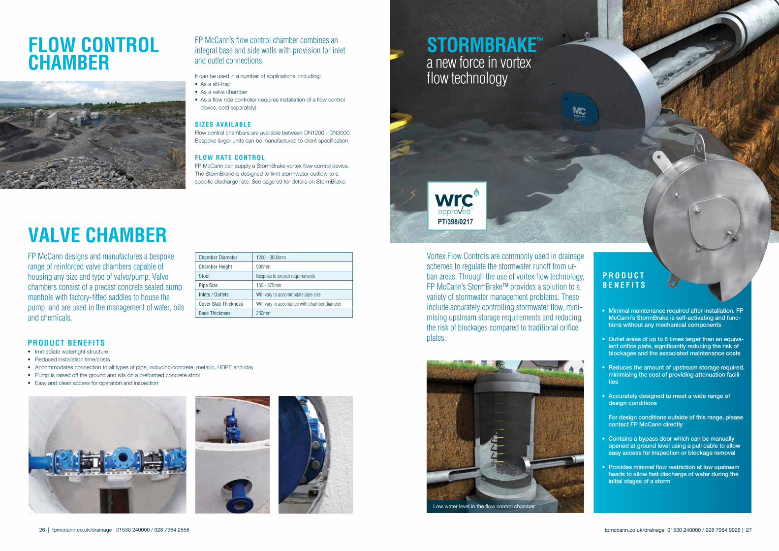
• Minimal maintenance required after installation. FP McCann’s StormBrake is self-activating and func-tions without any mechanical components
• Outlet areas of up to 6 times larger than an equiva-lent orifice plate, significantly reducing the risk of blockages and the associated maintenance costs
• Reduces the amount of upstream storage required, minimising the cost of providing attenuation facili-ties
• Accurately designed to meet a wide range of design conditions
For design conditions outside of this range, please contact FP McCann directly
• Contains a bypass door which can be manually opened at ground level using a pull cable to allow easy access for inspection or blockage removal
• Provides minimal flow restriction at low upstream heads to allow fast discharge of water during the initial stages of a storm
p R o D u c T b E N E F I T s
Lowwaterlevelintheflowcontrolchamber
Vortex Flow Controls are commonly used in drainage schemes to regulate the stormwater runoff from ur-ban areas. Through the use of vortex flow technology, FP McCann’s StormBrake™ provides a solution to a variety of stormwater management problems. These include accurately controlling stormwater flow, mini-mising upstream storage requirements and reducing the risk of blockages compared to traditional orifice plates.
sToRMbRAkE™
a new force in vortex flow technology
FP McCann’s precast concrete wide wall manholes have been designed with a tongue and groove dimension to accommodate the use of bituminous sealant. FP McCann’s approved sealant should be used at all times. The sealant requirement for wide wall manholes is 12mm x 120mm x 6m. When placing the sealing strip into position during installation, the ends of the strips must be overlapped by a minimum of 30mm and cut at an angle of 60 degree. The cut ends must then be pressed together. Full installation guidelines can be provided upon request or obtained from our website: fpmccann.co.uk
DN1200, 1500 AND 1800MM WIDE WAll MANholE chAMbERsA 130mm thick wide wall chamber, in combination with the Easi-Base unit, provides a sealed watertight manhole system. This robust design means that the requirement for a concrete surround is eliminated.
pRoDucT bENEFITs
• Quickandeasyinstallation
• Watertightstructure
• Safeanchorliftingsystem(sphericalheadliftingsystem)
• Greatercostsavingsassociatedwithusingprecast concreteoveratraditionalsystem
• Noconcretebackfillrequired,inaccordancewith‘SewersforAdoption’7thedition
• Moreenvironmentallyfriendlythanatraditionalsystem,almost40%lesscarbonomittedduringtheconcrete casting process
• Significantreductioninhealthandsafetyrisksassociatedwithusingprecastconcrete
WIDE WAllMANholEchAMbER
Please note: Wide Wall Manhole Chambers are manufactured with 3 x 45mm diameter lifting points to facilitate the safe anchor lifting system (spherical head lifting system).
28 | fpmccann.co.uk/drainage 01530 240000 / 028 7964 2558 fpmccann.co.uk/drainage 01530 240000 / 028 7954 9026 | 29
1520 KG
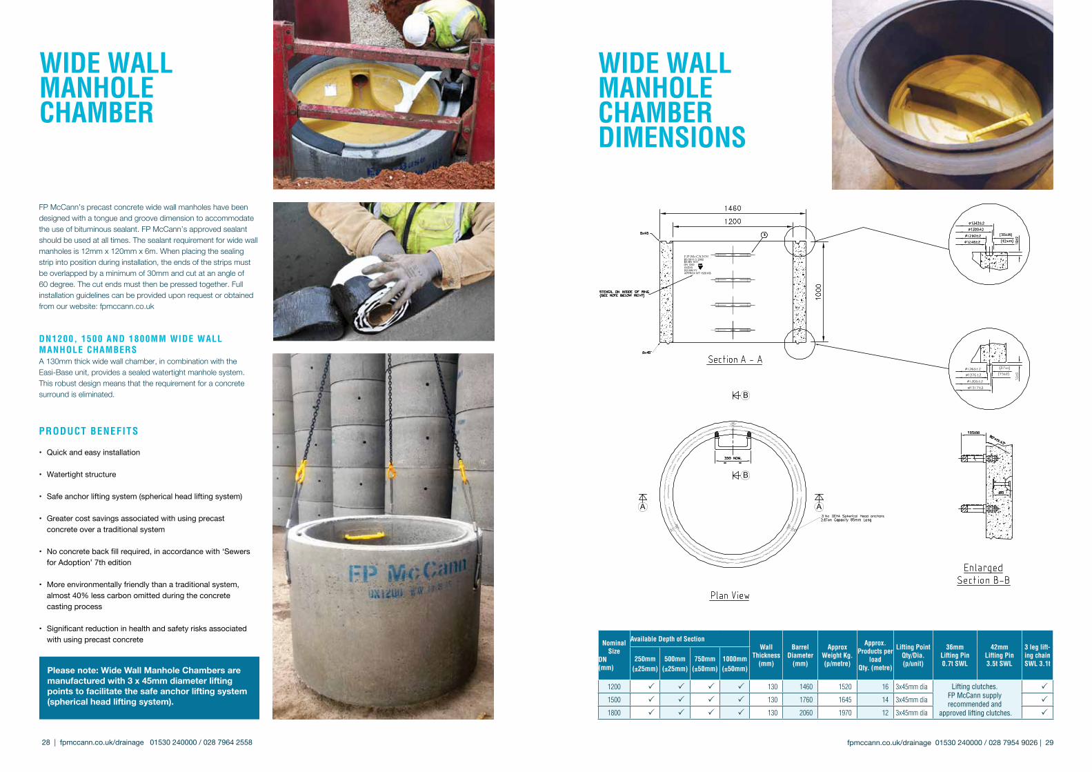
WIDE WAllMANholEchAMbERDIMENsIoNs
Nominal size
DN(mm)
Available Depth of sectionWall
Thickness(mm)
barrel Diameter
(mm)
Approx Weight kg. (p/metre)
Approx. products per
loadQty. (metre)
lifting pointQty/Dia. (p/unit)
36mm lifting pin 0.7t sWl
42mm lifting pin 3.5t sWl
3 leg lift-ing chain sWl 3.1t
250mm(±25mm)
500mm(±25mm)
750mm(±50mm)
1000mm(±50mm)
1200 P P P P 130 1460 1520 16 3x45mm dia Lifting clutches. FP McCann supply recommended and
approved lifting clutches.
P
1500 P P P P 130 1760 1645 14 3x45mm dia P
1800 P P P P 130 2060 1970 12 3x45mm dia P

fpmccann.co.uk/drainage 01530 240000 / 028 7954 9026 | 31 30 | fpmccann.co.uk/drainage 01530 240000 / 028 7964 2558
MANholE covER slAbs & AccEssoRIEs
Note: Cover Slab sizes 900-3000 are manufactured in accordance with BS 5911-3. DN3600 and 4000 cover slabs are generally designed in accordance with BS EN 1992-1-1, (for 30 units of Type HB loading, can also be designed to withstand 45 units of Type HB loading). * Weights for DN3600 and DN4000 are estimated weights based on solid slabs.
sTANDARD covER slAbs sTANDARD REDucING slAbs
chamber DN (mm)
outside Diameter (A) (mm)
slab Thickness (c) (mm)
opening configuration b Approx. Weight
(kg)
opening Diameter b
(mm)
Effective Depth (mm)
Approx.Weight
(kg)size (mm) location
900 1080 150600x600
CENTRAL 215675x675
1050 1240 150600x600
ECCENTRIC315675x675
750x750 CENTRAL
1200 1450 150600x600
ECCENTRIC 455 900 200 385675x675
750x600
1350 1580 170
600x600
ECCENTRIC650
1050 200 695675x675
750x6001200 200 550
1200x675 CENTRAL
1500 1740 175
600x600
ECCENTRIC980
90010501200
200200200
981835680
675x675
750x600
1200x675 CENTRAL
1800 2070 175
600x600
ECCENTRIC 1460900
10501200
200200200
149513501220
675x675
750x600
1200x675
2100 2380 200
600x600
ECCENTRIC 2180900
10501200
200200200
213026902540
675x675
750x600
1200x675
2400 2710 200
600x600
ECCENTRIC 2800900
10501200
200200200
281526902540
675x675
750x600
1200x675
2700 3030 230
600x600
ECCENTRIC 3750900
10501200
200200250
369535503410
675x675
750x600
1200x675
3000 3420 200
600x600
ECCENTRIC 4970900
10501200
200200200
497049704970
675x675
750x600
1200x675
*3600 Two Piece
4000 300
600x600
ECCENTRIC 9250
Covers to suit Manholes greater than or equal to 1.5m deep cover level to pipe soffit.
*3600mm and 4000mm diameter cover slabs come in a
2 piece unit
675x675
750x600
1200x675
*4000Two Piece
4500 300
600x600
ECCENTRIC 11700675x675
750x600
1200x675
sTANDARD lANDING slAbs
chamber section (DN)
outside Diameter (A)
opening Diameter (b)
slab Thickness (c)
Approx. Weight (kg.)
1500 1730 900 200 826
1800 2050 900 200 1292
2100 2375 900 200 2030
2400 2705 900 200 2600
2700 3025 900 200 3880
3000 3330 900 200 4500
covER slAbs
C
A
B
C
A
B
lANDING slAbs
REDucING slAbs
Multipleaccess/otheraccesssizedcoverslabscanbemadetoorder
A
C
B
B A
C
size (A) (mm)
slab Thickness (c) (mm)
openings (b) (mm)
Approx. Weight
(kg)
1125x1125 75 600x600/675x675/750x600 140
1125x1125 150 600x600/675x675/750x600 290
loThIAN slAb
Note: A 600 x 600 eccentric corbel slab is also available when using a ladder BS EN 1917 and BS 5911
Type2600x600
Type2675x675
Type2750x600
Type2750x750
Type21200x675 Type1600x600Eccentric(Corbel)
FP McCann manufactures a full range of adjusting units and corbel slabs that have the following advan-tages:
• Designed as seating for manhole cover
• Eliminates laying engineering bricks on-site
• Quicker to lay, ensuring reduced labour costs
• 65mm thick – similar to brickwork
• Sits on top of the manhole cover slab
• Eliminates brickwork vertical joint weakspots
• Quality product produced by vibration process
• Comprehensive strength, similar to Class B.Eng bricks
ADJusTING uNITs & coRbEl slAbs
Manhole Type
Diameter (mm)
opening size (mm)
No. per pack
Thickness (mm)
Weight (kg)
Type 2 1000 600 x 600 15 65 70
Type 2 1000 675 x 675 15 65 55
Type 2 1000 750 x 600 15 65 60
Type 2 1000 750 x 750 10 65 45
Type 2 1575 x 1050 1200 x 675 6 75 160
Type 1 1175 x 1025 600 x 600 10 65 125
NB: All dimensions are in mm, unless stated otherwise

fpmccann.co.uk/drainage 01530 240000 / 028 7954 9026 | 33 32 | fpmccann.co.uk/drainage 01530 240000 / 028 7964 2558
Note: Gullies and Gully cover slabs manufactured in accordance with BS 5911-6
GullIEs
The Gully Cover Slab is designed as seating for a gully grate
sTANDARD Gully covER hoRsEshoE Gully covER
pRoDucT bENEFITs
• Quicker to lay, ensuring reduced labour costs
• Use on top of 450mm diameter gully
• Eliminates laying engineering bricks on-site
• Sits flush to kerb for enhanced stability
• 100mm thick single piece unit
• Eliminates brickwork vertical joint ‘weakspots’
• Greater stability than brickwork
• Quality product produced by vibration process
• Compressive strength similar to Class B.Eng. bricks
Gully covER slAbs
pRoDucT bENEFITs
• The seal has been cast-in, thus preventing loss or damage on-site
• An integral seal and rodding eye for universal sealing characteristics
• The rodding eye closure has been recessed into the concrete to help
eliminate dislodgment
• Reduced thickness, giving reduced weight and a smaller footprint for
better vehicle utilisation
• Improved system that helps prevent any discharge of oil
• The gully is fully universal, suitable for all plastic and clay drainage
products from 160mm to 186mm diameter
• Does not lose shape
• Does not float (self weight inhibits flotation)
GullIEs & slAbs RANGE
Dimensions (mm) Nominal Weight
(kg)
Approx. capacity (litres)
No. per loadDiameter
Internal Depth outlet
375 750 150 180 51 66
375 900 150 200 67 66
450 750 150 215 71 60
450 900 150 255 95 60
450 1050 150 270 118 60
450 1200 150 280 142 60
Dimensions (mm) standard horseshoe
length (mm) 750 600
Width (mm) 650 650
Thickness (mm) 100 100
Weight (kg) 70 58
hole size (mm) 450 450
Qty/pack 12 12
AWARD-WINNING sAFETy soluTIoN FoR MANholE coNsTRucTIoN
Clients, consultant engineers, contractors and suppliers all have a duty to mitigate hazards on-site, whenever reasonably practicable. One such hazard identified is the risk of operatives falling through manhole openings, particularly during the construction process and also in follow-up maintenance work.
Working with partners Severn Trent Water, engineer Grontmij and contractor to the water sector, Morgan Sindall plc, FP McCann has designed an award-winning safety solution. Our fall arrest system allows for safe working around the manhole opening prior to the fitting of the ironwork.
In the construction of a manhole, operatives often work unprotected from the opening at surface level when the final stages of completion occur. This includes the final brickwork up to the manhole frame and the mortar bedding of the frame itself.
With most standard cover slabs, the access point for man entry is open and it is left to the contractor to cover on-site. In many site situations, these openings remain for a number of days while phases of work are completed. Our fall arrest system immediately addresses this problem. The future production of all standard access cover slabs will incorporate the optional protective grid, which will remain in the slab even when the final D400 steel cover and frame are set in place at surface level.
The galvanised mild steel grid is available in four standard sizes:• 610mm x 610mm• 675mm x 675mm• 750mm x 600mm• 1200mm x 675mm
The fall arrest grid is seated on load-bearing corners cast into a standard range of manhole cover slabs. If a temporary fall arrest system is required, once the construction of the manhole is complete, the grid can be removed prior to the fitting of the ironwork. Alternatively, it can be a permanent fixture, left in place beneath the manhole lid. The spacing between the bars allows for ease of inspection and jetting of the manhole base during maintenance work.
UNPROTECTED
FAll ARREsTsysTEM
Gully lIFTER
fpmccann.co.uk/drainage 01530 240000 / 028 7954 9026 | 35 34 | fpmccann.co.uk/drainage 01530 240000 / 028 7964 2558
chamber size (mm)
cover
600x450 Frame and lid places straight on top of unit
750x600 Below surface slab with 600x450 access, allowing use of frame and lid
1000x675 Below surface slab with 600x450 access, allowing use of frame and lid
1200x750 Light or heavy duty below surface slab with 600x600 access, allowing use of standard steel access hole cover
NOTE:For HIC’s placed in depths greater than 1.5m, we recommend the use of a concrete surround.
ChamberSections
SlabLid Frame
FP McCann
housEINspEcTIoNchAMbERs
FP McCann’s precast concrete inspection chambers are available in four common sizes: 600 x 450, 750 x 600, 1000 x 675 and 1200 x 750mm. Manufactured in accordance with BS EN 1917 / BS5911, each sec-tion has a tongue and groove joint and can be sealed with a sand and cement mortar or bitumen sealant, in the same fashion as a circular manhole and chamber ring.
To complete the chamber, FP McCann has a range of covers and ground level components. FP McCann’s frame (also known as a surround) and lid combination is designed to sit flush with the top course, such as tarmac or concrete surfacing or in grassy areas.
The lid itself features an anti-slip chequered finish and recessed lifting points to allow removal from the frame by use of standard lifting eyes.
Description units (mm)
**Weight per unit (mm)
No. of units per
pallet
Wall/slab
thickness (mm)
600x450x150 section 40 12 40
600x450x225 section 65 8 40
600x450x300 section 85 6 40
600x450x100 frame 45 8 100
600x450x55 lid 50 16 55
750x600x150 section 60 6 55
750x600x250 section 100 4 55
750x600x70 cover slab (600x450 access)
75 8 *70
1000x675x150 section 94 6 60
1000x675x250 section 130 4 60
1000 x 675 x 76 cover slab (600x450 access)
130 8 *75
1200x750x150 section 120 6 75
1200x750x250 section 200 4 75
1200x750x80 cover slab (600x600 access)
185 6 *80
ADD-A-sTEp™ modular manhole ladder
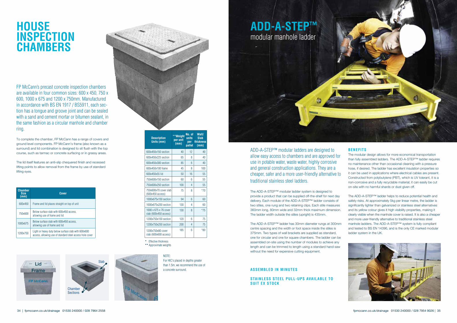
ADD-A-STEP™ modular ladders are designed to allow easy access to chambers and are approved for use in potable water, waste water, highly corrosive and general construction applications. They are a cheaper, safer and a more user-friendly alternative to traditional stainless steel ladders.
The ADD-A-STEP™ modular ladder system is designed to provide a product that can be supplied off-the-shelf for next day delivery. Each module of the ADD-A-STEP™ ladder consists of two stiles, one rung and two retaining clips. Each stile measures 360mm long, 80mm wide and 32mm thick maximum dimension. The ladder width outside the stiles (upright) is 435mm.
The ADD-A-STEP™ ladder has 30mm diameter rungs at 300mm centre spacing and the width or foot space inside the stiles is 375mm. Two types of wall brackets are supplied as standard, one for circular and one for square chambers. The ladder can be assembled on-site using the number of modules to achieve any length and can be trimmed to length using a standard hand saw without the need for expensive cutting equipment.
AssEMblED IN MINuTEs
sTAINlEss sTEEl pull-ups AvAIlAblE To suIT Ex sTock
bENEFITsThe modular design allows for more economical transportation than fully assembled ladders. The ADD-A-STEP™ ladder requires no maintenance other than occasional cleaning with a pressure hose, if desired. The ladder has excellent insulation properties so it can be used in applications where electrical cables are present. Constructed from polybutylene (PBT), which is UV tolerant, it is a non-corrosive and a fully recyclable material; it can easily be cut on-site with no harmful shards or dust given off.
The ADD-A-STEP™ ladder helps to reduce potential health and safety risks. At approximately 5kg per linear metre, the ladder is significantly lighter than galvanized or stainless steel alternatives and its yellow colour gives it high visibility properties, making it clearly visible when the manhole cover is raised. It is also a cheaper and more user-friendly alternative to traditional stainless steel manhole ladders. The ADD-A-STEP™ system is fully compliant and tested to BS EN 14396, and is the only CE marked modular ladder system in the UK.
* Effective thickness** Approximate weights

fpmccann.co.uk/drainage 01530 240000 / 028 7954 9026 | 37 36 | fpmccann.co.uk/drainage 01530 240000 / 028 7964 2558
pRoDucT spEcIFIcATIoNsBS EN 13101 Plastic Encapsulated StepsWIS 4-33-01: 1990 Polypropylene Encapsulated Steps
pRoDucT ApplIcATIoNsConcrete manholes and inspection chambers.Renovation of existing structures.
MATERIAls The plastic encapsulated ladder has a bright yellow coating and is made from high impact virgin polypropylene copolymer plastic. If the ladder is to be subject to prolonged exposure to daylight then black or UV stabilised material should be specified. It is reinforced with structural steel.
pERFoRMANcEPull out load: 7.5kN minimum, when fitted in accordance with manufacturer’s instructionsDeflection under load: 5mm maximum at 2.5kNPermanent Set: 0 mm at 2.5kNImpact: 20kg weight from 1 metre, no crackingChemical Resistance: At least pH2 to 12Integrity of plastic: 2M ohm at 500 volts DCThickness of plastic: 3mm minimumMinimum cross section: 25mm diameter
pRoDucT bENEFITs•Excellentcorrosionresistance•Visibility•Nosharpedges•Eliminatesneedtospecifyexactlengthorfiton-site•Steelreinforcementgivespredictabledeflectionunderload withoutcausingbrittlefailure
This system ladder gives the user benefits of a durable plastic encapsulated ladder without the need to specify an exact length or fit on-site. In addition, a single specification can be used for all depths of access.
plAsTIcENcApsulATEDlADDERs& RuNGs
The handhold entry pole system is suitable for aiding maintenance engineers in the initial entry into a manhole from the surface level. Once fitted, the entry pole is a permanent fixture within the manhole, which is stored in the lowered position beneath the level of the cover. When required, the entry pole can be easily extended by simply hooking the easy-to-reach loop located at the top of the pole, pulling the handle upwards and twisting, locking into position. The handhold then provides a stable support to aid the entrance of the manhole, as well as a clear visual indication of the location of the manhole, when open. This helps prevent injury of other people in the area. Once the engineer has used the entry pole to aid their return to the surface, the pole is simply twisted to unlock it from the raised position and lowered back into the manhole, ready for the next time it is needed.
spEcIFIcATIoNThe handhold has a pole length of 1200mm and can be assembled to give three different distances from the pole to the wall. This is designed to accommodate different cover positions.
290 MM25 min.
25 min.
25 min.
20 MIN.25 min.
10 MAx.
125
mm
50 m
in. T
AIl
leN
GTH
FACe oF WAll
pRoDucT bENEFITs
• Helps the user find the first step safely
• Creates visual aid to indicate location of manhole to other people in the area
• Easy to fit
• Easy to raise and lower
• High strength for ultimate safety
• Low cost
• Can be fitted to any Caswick step
• Two projections for round or flat walled manholes
hANDholDENTRy polEsysTEM
38 | fpmccann.co.uk/drainage 01530 240000 / 028 7964 2558
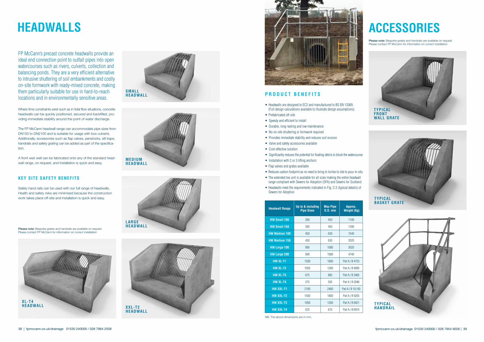
FP McCann’s precast concrete headwalls provide an ideal end connection point to outfall pipes into open watercourses such as rivers, culverts, collection and balancing ponds. They are a very efficient alternative to intrusive shuttering of soil embankments and costly on-site formwork with ready-mixed concrete, making them particularly suitable for use in hard-to-reach locations and in environmentally sensitive areas.
Where time constraints exist such as in tidal flow situations, concrete headwalls can be quickly positioned, secured and backfilled, pro-viding immediate stability around the point of water discharge. The FP McCann headwall range can accommodate pipe sizes from DN150 to DN2100 and is suitable for usage with box culverts. Additionally, accessories such as flap valves, penstocks, silt traps, handrails and safety grating can be added as part of the specifica-tion.
A front weir wall can be fabricated onto any of the standard head-wall range, on request, and installation is quick and easy.
kEy sITE sAFETy bENEFITs
Safety hand rails can be used with our full range of headwalls. Health and safety risks are minimised because the construction work takes place off-site and installation is quick and easy.
p R o D u c T b E N E F I T s
• Headwalls are designed to EC2 and manufactured to BS EN 13369. (Full design calculations available to illustrate design assumptions).
• Prefabricated off-site
• Speedy and efficient to install
• Durable, long-lasting and low maintenance
• No on-site shuttering or formwork required
• Provides immediate stability and reduces soil erosion
• Valve and safety accessories available
• Cost-effective solution
• Significantly reduces the potential for floating debris to block the watercourse
• Installation with 2 or 3 lifting anchors
• Flap valves and grates available
• Reduces carbon footprint as no need to bring in lorries to site to pour in-situ
• The extended toe unit is available for all sizes making the entire headwall range compliant with Sewers for Adoption (SFA) and Sewers for Scotland
• Headwalls meet the requirements indicated in Fig. C.5 (typical details) of Sewers for Adoption
hEADWAllsPlease note: Bespoke grates and handrails are available on request.Please contact FP McCann for information on correct installation
fpmccann.co.uk/drainage 01530 240000 / 028 7954 9026 | 39
AccEssoRIEs
MEDIuM hEADWAll
NB: The above dimensions are in mm.
TypIcAl FRoNT WAll GRATE
TypIcAl bAskET GRATE
TypIcAl hANDRAIl
headwall Range up to & includingpipe sizes
Max pipeo.D. mm
Approx. Weight (kg)
hW small 100 300 450 1100
hW small 150 300 450 1390
hW Medium 100 450 630 1540
hW Medium 150 450 630 2020
hW large 100 900 1080 3020
hW large 200 900 1080 4740
hW xl-T1 1500 1800 Part A / B 4725
hW xl-T2 1050 1260 Part A / B 4095
hW xl-T3 675 885 Part A / B 3465
hW xl-T4 375 505 Part A / B 2646
hW xxl-T1 2100 2460 Part A / B 10,150
hW xxl-T2 1500 1800 Part A / B 9205
hW xxl-T3 1050 1260 Part A / B 8421
hW xxl-T4 525 675 Part A / B 6915
lARGE hEADWAll
xl-T4 hEADWAll xxl-T2
hEADWAll
sMAll hEADWAll
Please note: Bespoke grates and handrails are available on request.Please contact FP McCann for information on correct installation
fpmccann.co.uk/drainage 01530 240000 / 028 7954 9026 | 41
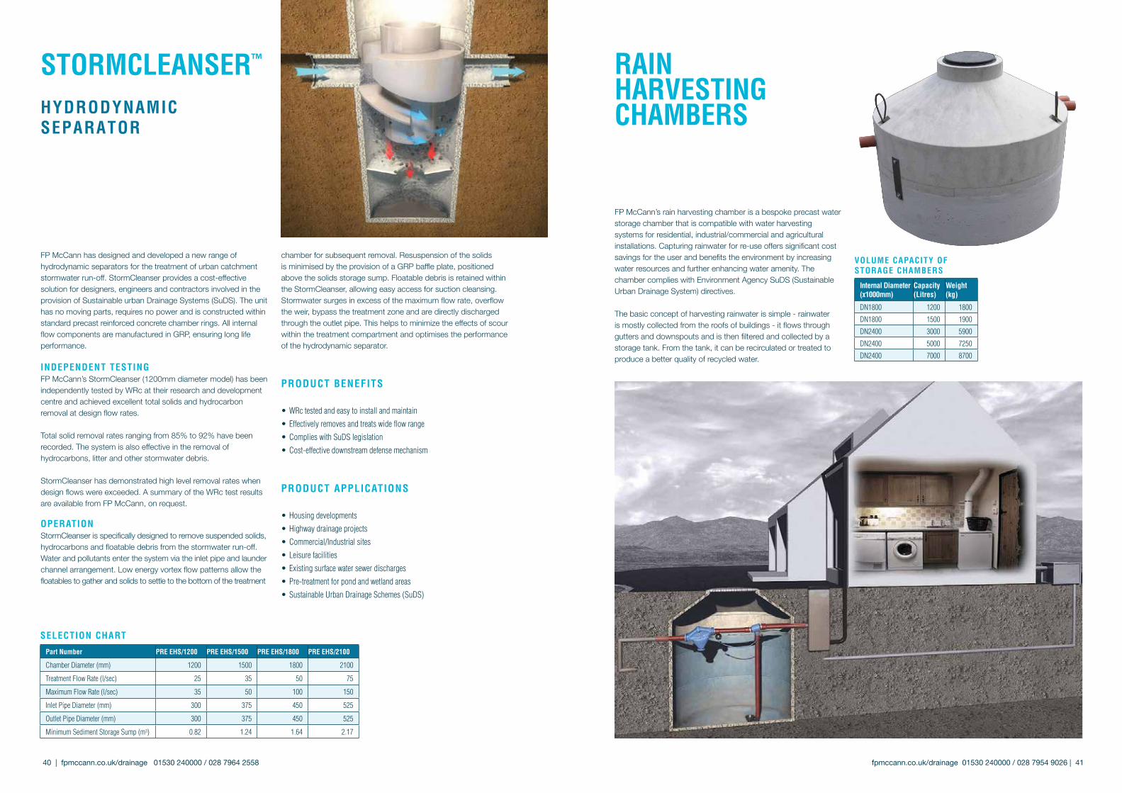
FP McCann has designed and developed a new range of hydrodynamic separators for the treatment of urban catchment stormwater run-off. StormCleanser provides a cost-effective solution for designers, engineers and contractors involved in the provision of Sustainable urban Drainage Systems (SuDS). The unit has no moving parts, requires no power and is constructed within standard precast reinforced concrete chamber rings. All internal flow components are manufactured in GRP, ensuring long life performance.
INDEpENDENT TEsTING FP McCann’s StormCleanser (1200mm diameter model) has been independently tested by WRc at their research and development centre and achieved excellent total solids and hydrocarbon removal at design flow rates.
Total solid removal rates ranging from 85% to 92% have been recorded. The system is also effective in the removal of hydrocarbons, litter and other stormwater debris.
StormCleanser has demonstrated high level removal rates when design flows were exceeded. A summary of the WRc test results are available from FP McCann, on request.
opERATIoNStormCleanser is specifically designed to remove suspended solids, hydrocarbons and floatable debris from the stormwater run-off. Water and pollutants enter the system via the inlet pipe and launder channel arrangement. Low energy vortex flow patterns allow the floatables to gather and solids to settle to the bottom of the treatment
sElEcTIoN chART
part Number pRE Ehs/1200 pRE Ehs/1500 pRE Ehs/1800 pRE Ehs/2100
Chamber Diameter (mm) 1200 1500 1800 2100
Treatment Flow Rate (l/sec) 25 35 50 75
Maximum Flow Rate (l/sec) 35 50 100 150
Inlet Pipe Diameter (mm) 300 375 450 525
Outlet Pipe Diameter (mm) 300 375 450 525
Minimum Sediment Storage Sump (m3) 0.82 1.24 1.64 2.17
chamber for subsequent removal. Resuspension of the solids is minimised by the provision of a GRP baffle plate, positioned above the solids storage sump. Floatable debris is retained within the StormCleanser, allowing easy access for suction cleansing. Stormwater surges in excess of the maximum flow rate, overflow the weir, bypass the treatment zone and are directly discharged through the outlet pipe. This helps to minimize the effects of scour within the treatment compartment and optimises the performance of the hydrodynamic separator.
pRoDucT bENEFITs
• WRc tested and easy to install and maintain
• Effectively removes and treats wide flow range
• Complies with SuDS legislation
• Cost-effective downstream defense mechanism
pRoDucT ApplIcATIoNs
• Housing developments
• Highway drainage projects
• Commercial/Industrial sites
• Leisure facilities
• Existing surface water sewer discharges
• Pre-treatment for pond and wetland areas
• Sustainable Urban Drainage Schemes (SuDS)
sToRMclEANsER™ hyDRoDyNAMIcsEpARAToR
FP McCann’s rain harvesting chamber is a bespoke precast water storage chamber that is compatible with water harvesting systems for residential, industrial/commercial and agricultural installations. Capturing rainwater for re-use offers significant cost savings for the user and benefits the environment by increasing water resources and further enhancing water amenity. The chamber complies with Environment Agency SuDS (Sustainable Urban Drainage System) directives.
The basic concept of harvesting rainwater is simple - rainwater is mostly collected from the roofs of buildings - it flows through gutters and downspouts and is then filtered and collected by a storage tank. From the tank, it can be recirculated or treated to produce a better quality of recycled water.
Internal Diameter (x1000mm)
capacity (litres)
Weight(kg)
DN1800 1200 1800
DN1800 1500 1900
DN2400 3000 5900
DN2400 5000 7250
DN2400 7000 8700
voluME cApAcITy oF sToRAGE chAMbERs
RAINhARvEsTINGchAMbERs
40 | fpmccann.co.uk/drainage 01530 240000 / 028 7964 2558

42 | fpmccann.co.uk/drainage 01530 240000 / 028 7964 2558
Fit a pipe lifter to your excavator and you can lay concrete pipes in around half the time with less cost and less hassle – but with greater safety.
Safer. No operative needed on vehicle during off-loading or in trench during pipe laying.easier. Simple to use. No special equipment & minimal training required.Faster. Around 50% saving on installation time.Cheaper. Fewer operatives plus greater productivity.
The Concrete Pipe Lifter makes light work of the installation of waste water pipelines. Within seconds, it can be attached to your excavator using a quick-hitch coupling. There are no hydraulic links or additional energy requirements.
There is no need for anyone to stand on the bed of the vehicle during off-loading (the biggest cause of accidents during pipe laying). There’s no need for anyone to stand in the trench during installation and there are no slings or chains to trap hands and fingers. The whole operation is around 50% faster and you can reduce the size of your pipe laying team, so costs are lower too.
The Concrete Pipe Lifter is suitable for standard UK specification BS EN1916 concrete pipes from DN300 to DN1200.
The Manhole Lifter is a companion device that makes lifting manhole rings a safe and easy, one-man operation. It eliminates the risk of vehicle falls during off-loading. There are two versions available for precast concrete manhole rings from DN900 to DN1800 and from DN2100 to DN3000. It’s capable of lifting rings from 250 mm to 1000 mm deep.
To buy or rent the Pipe lifter, contact BPDA’s supply partnersvisit: concretepipelifter.co.uk for details
fpmccann.co.uk/drainage 01530 240000 / 028 7954 9026 | 43
MEchANIcAlcoNcRETEpIpE lIFTER
pRoDucT lIFTERs REQuIRED NoTEs
900 to 1800 Standard Chamber Rings and Soak-away
3No M24 Lifting Eye Pins inserted into holes through the ring wall.
Eyes should be on the INSIDE of the ring.
2100 to 3000 Standard Chamber Rings and Soak-away
4No M30 Lifting Eye Pins inserted into holes through the ring wall.
Eyes should be on the INSIDE of the ring.
3600 Standard Chamber Rings 3No RD30 Lifting Loops screwed into the top face of the ring
Please be aware that the loops are not intended for prolonged use.
4000 Standard Chamber Rings (2 part) 4No RD36 Lifting Loops screwed into the top face of the ring
Please be aware that the loops are not intended for prolonged use. Instructions for handling are shown on the product itself.
1200 to 1800 Wide-Wall Chamber Rings 3No 5t Spherical Head Clutch Attach to the OUTSIDE of the ring.
300 to 1200 Standard Pipes and Fittings Pipe Grab (below) or SlingsSlings are not supplied by FP McCann. DO NOT USE HOOKS! These can damage the pipes and can be dangerous!
1350 to 2100 Standard Pipes and Fittings
10t Spherical Head Clutch and Chain Sling Set
Clutches and chains allow safe lift and easy installation of units.
2400 Standard Pipes and Fittings 20t Spherical Head Clutch and Chain Sling Set 12-20 tonne shackle 2 leg lifting chain only
All Diameters of Standard Cover Slabs None Chain Hooks can be attached directly to all of our standard slabs without further equipment required.
Small Headwalls 2 No. 24mm Lifting Loops Please be aware that the loops are not intended for prolonged use. Instructions for handling are shown on the product itself. Medium & Large Headwalls 3 No. 24mm Lifting Loops
MECHANICAL GRABS - The quicker, easier and safer option for handling rings and pipes. These attachments connect to site plant and allow off-loading and in-stallation without any need for access to the trailer bed. Mechanical grabs are available for pipe diameters DN300 to 1200 and for ring diameters of DN900 to 3000. For further information, contact your sales representative. Easi-bases, headwalls and flow-control chambers come supplied with the correct lifters ready for use. Catchpits should be handled with a mechanical grab. All lifters supplied by FP McCann come with appropriate certification and are ready for use. Lifters should be incorporated into the contractors lifting equipment inspection regime under LOLER regulations or disposed of after use.
All of the precast concrete drainage products manufactured by FP McCann feature a lifting system to allow safe off -loading and installation in an efficient manner. Each system is suited to each type of product. The information below will allow you to determine what lifting attachments are required. This list is not exhaustive and may be subject to change. Please contact FP McCann’s technical department if you are unsure about any aspect of lifting. Please be aware that it is the contractor’s responsibility to ensure all lifts are safe and compliant with legal requirements.
If you do not have the correct lifting equipment, please contact our sales department who will be happy to assist. Please ensure you have ordered lifting equipment to arrive on-site, ready for when your load is delivered! Unless otherwise stated, FP McCann will only supply the eyes or attachments. Correct chains will need to be sourced by the contractor. Unless otherwise specified, access to the trailer will be required to insert the attachments.
kNoW youR lIFTERs
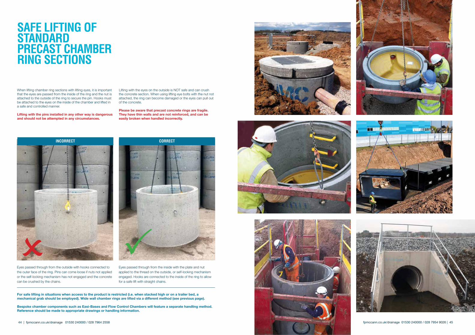
For safe lifting in situations when access to the product is restricted (i.e. when stacked high or on a trailer bed, a mechanical grab should be employed). Wide wall chamber rings are lifted via a different method (see previous page).
Bespoke chamber components such as easi-Bases and Flow Control Chambers will feature a separate handling method. Reference should be made to appropriate drawings or handling information.
44 | fpmccann.co.uk/drainage 01530 240000 / 028 7964 2558
When lifting chamber ring sections with lifting eyes, it is important that the eyes are passed from the inside of the ring and the nut is attached to the outside of the ring to secure the pin. Hooks must be attached to the eyes on the inside of the chamber and lifted in a safe and controlled manner.
lifting with the pins installed in any other way is dangerous and should not be attempted in any circumstances.
Lifting with the eyes on the outside is NOT safe and can crush the concrete section. When using lifting eye bolts with the nut not attached, the ring can become damaged or the eyes can pull out of the concrete.
Please be aware that precast concrete rings are fragile. They have thin walls and are not reinforced, and can be easily broken when handled incorrectly.
Eyes passed through from the outside with hooks connected to the outer face of the ring. Pins can come loose if nuts not applied or the self-locking mechanism has not engaged and the concrete can be crushed by the chains.
Eyes passed through from the inside with the plate and nut applied to the thread on the outside, or self-locking mechanism engaged. Hooks are connected to the inside of the ring to allow for a safe lift with straight chains.
INcoRREcT coRREcT
sAFE lIFTING oF sTANDARDpREcAsT chAMbER RING sEcTIoNs
fpmccann.co.uk/drainage 01530 240000 / 028 7954 9026 | 45
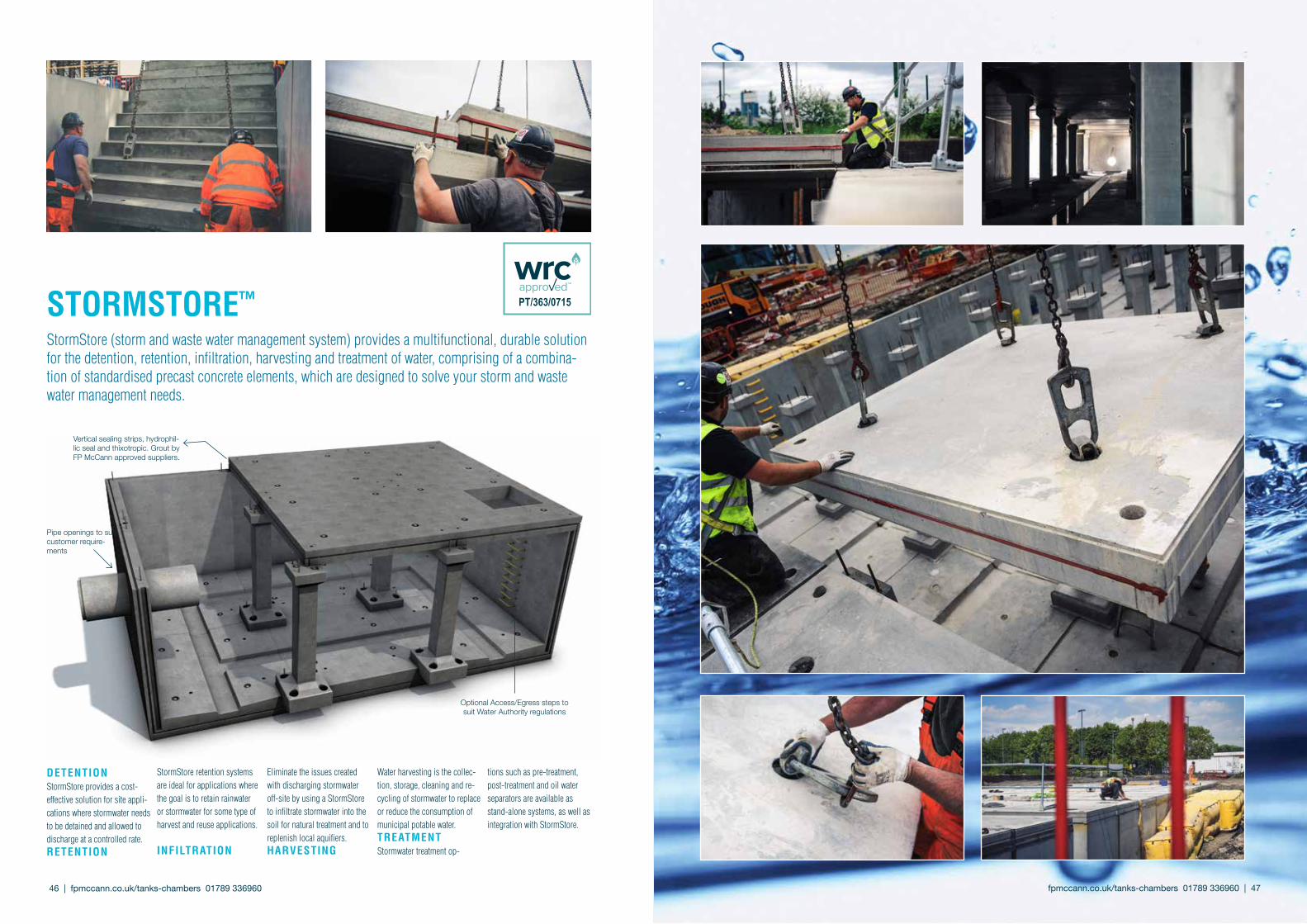
cATTlEslATs
sToRMsToRE™
StormStore (storm and waste water management system) provides a multifunctional, durable solution for the detention, retention, infiltration, harvesting and treatment of water, comprising of a combina-tion of standardised precast concrete elements, which are designed to solve your storm and waste water management needs.
DETENTIoNStormStore provides a cost-effective solution for site appli-cations where stormwater needs to be detained and allowed to discharge at a controlled rate.RETENTIoN
StormStore retention systems are ideal for applications where the goal is to retain rainwater or stormwater for some type of harvest and reuse applications.
INFIlTRATIoN
Eliminate the issues created with discharging stormwater off-site by using a StormStore to infiltrate stormwater into the soil for natural treatment and to replenish local aquifiers.hARvEsTING
Water harvesting is the collec-tion, storage, cleaning and re-cycling of stormwater to replace or reduce the consumption of municipal potable water.TREATMENTStormwater treatment op-
tions such as pre-treatment, post-treatment and oil water separators are available as stand-alone systems, as well as integration with StormStore.
Pipe openings to suit customer require-ments
Optional Access/Egress steps to suit Water Authority regulations
Vertical sealing strips, hydrophil-lic seal and thixotropic. Grout by FP McCann approved suppliers.
fpmccann.co.uk/tanks-chambers01789336960| 47 46 | fpmccann.co.uk/tanks-chambers01789336960

fpmccann.co.uk/tanks-chambers01789336960| 49 48 | fpmccann.co.uk/tanks-chambers01789336960
•Up to 2.5m overburden with a 10kN/m2 surcharge•100 year design life•Complies with watertightness class 1 of BS EN 1992-3•Assumed water table at roof slab level• Suitable for use within wastewater and stormwater
drainage systems
INsTAllATIoN bENEFITs
•Potential savings on temporary works•Reduced disruption due to speed of installation•No need to wait 28 days before back filling. Backfilling can follow
on after installation•No requirement for in-situ concrete topping to roof slab•No requirement for on-site in-situ benching•No requirement for in-situ joint-stitching
bENEFITs oF sToRMsToRE™
MANuFAcTuRING bENEFITs
• Manufactured locally• Bespoke inlets and outlets• An adoptable system which can cater for the 1 in 30 and 1 in 100
year storm event• FP McCann uses state-of-the-art tooling to manufacture products
of the highest quality• A fully modular system encompassing inherent health and safety
benefits
MAINTENANcE AND clEANING bENEFITs
•The StormStore system excels where most other systems fail, incorporating features that provide maximum system performance and life cycles. As with all stormwater systems, inspection and maintenance of the StormStore system is vital for satisfactory performance and extended life cycle of the stormwater management system
•A self-cleansing and easy maintainable system which includes silt collection areas
•Designed to create safe walking channels during the maintenance, cleaning and inspection process
• Easily inspected visually, offering reduced inspection costs• System provides clear lines of sight to aid health and safety during
maintenance and cleaning
DEsIGN bENEFITs
•Complies with BS EN 1992•Grated inlets may also be incorporated to accommodate surface
stormwater flows directly into the StormStore system, reducing the requirements for conventional site drainage components. Any grated inlets may also include pre-treatment devices for pollutant removal
•Standard units reduce design cost•No requirement for in-situ structural topping to roof slab –
offering reduced fill depths and cost savings•Fully accessible system with the option of including step rungs or
ladders•A fully modular system that brings with it inherent health and
safety benefits•The design and performance meets CESWI 7th edition•Standard internal heights from underside of roof slab to the chan-
nel inverts of 1500, 1800, 2100 and 2400mm. All available with either 1 in 4 or 1 in 20 benching gradients
•The system fully meets CE Marking requirements•The system and installation is approved by WRc•Complies with Sewers for Adoption 7th edition and Sewers for
Scotland 3rd Edition 2015•Precast elements manufactured using concrete with a DC4 design
chemical class in accordance with BRE SD1

50 | fpmccann.co.uk/tanks-chambers01789336960 fpmccann.co.uk/tanks-chambers01789336960| 51
The production of water-impermeable surfaces in construction is inevitable. This includes roof areas on buildings, car parks, loading bays and road pavements. The provision of these surfaces interrupts the natural drainage process, creating increased stormwater run-off in respect of both volume and flow rate.
In many cases, this increase in stormwater flow and volume is a problem as the local sewer or watercourse does not have the sufficient capacity to cope. This problem could be alleviated by an increase in the size of the stormwater sewer or watercourse, thus providing the capacity within the drainage system to cope with the increased surface water. This, however, may be expensive, cause major infrastructure disruption, and can often be completely unfeasible.
Legislation under Planning Policy Statement 25 and Building Regulations approved Document H3 for flood risk assessment (SuDS), has created the need for planners and developers to design and install effective stormwater management systems.
The types of systems that can be employed to overcome these issues are well documented and varied. Quite often they can be very technically demanding in their operation, maintenance and construction. The selection of a system will depend on site constraints, position, expected loading, geographical limitations and inevitably cost.
The Storm-Hold system offers a complete solution to the stormwater attenuation problem and utilises a tried, tested and approved method of stormwater storage. FP McCann can provide the complete package of design, product specification and supply of products and installation advice.
pRoDucT FEATuREs
• Available in a range of sizes• Can use and combine a number of techniques and products such as pipes, culverts, tanks, manifold systems and soakaways• A complete solution with all connections• Established and familiar products• Can be laid in short lengths• The system can be adapted to load-bearing and non-load bearing applications• 120 year design life• Adoptable by water companies• Manufactured in accordance with a BSI accredited quality management system conforming to ISO 9001• Available straight from stock
sTRucTuRAlThe inherent structural strength of concrete is well documented and can be designed to meet the severest of loading criteria. Storm-Hold systems can be tailored to suit low load situations, for example, when the tank is to be situated below verges or gardens.
bENEFITs• System can be designed specifically to suit the application• Quick construction using a standard joint• No need for fabrication on-site or external specialist contractors• Straightforward installation using known techniques, no need to retrain• Can be installed under roads and car parks• Can cope with construction plant loading• Flotation is not a concern – no need for geotechnical anchors when located below the water table• Long term solution
DEsIGNThe design of the system can be tailored to suit most structural and hydraulic criteria.
RElEvANT lEGIslATIoN/ INFoRMATIoN• Planning Policy Statement 25 (PPS25) December 2009 Department of Communities and Local Government (DCLG)• Future Water February 2008, Department for Environment, Food and Rural Affairs (DEFRA)• The Pitt Review, Learning Lessons from the 2007 floods by Sir Michael Pitt• The Code for Sustainable Homes February 2008, Department for Communities and Local Government (DCLG)• The SuDS Manual 2007, CIRIA C697• Sustainable drainage systems - Hydraulic, structural and water quality advice 2004, CIRIA C609• Flood and Water Management Act 2010
FP McCann’s Storm-Hold systems can be designed to suit a wide range of construction projects and drainage schemes. Precast concrete attenuation components include products such as side entry manholes, stop end bends and spigot and socket end wall pipes. These products can either be engineered into an on-line sewer pipe system or utilised off-line as single or multiple stormwater holding tanks. All FP McCann storm attenuation products comply with the requirements set out within ‘Sewers for Adoption 7th Edition’ and are made from Kite marked precast concrete components, which comply with the relevant Standards: BS EN 1916 / BS 5911-1 and Manholes BS EN 1917.
sToRM-holD™lARGE DIAMETER pIpE sToRMWATER MANAGEMENT sysTEM
50 | fpmccann.co.uk/stormhold 01789 336960 fpmccann.co.uk/stormhold 01789 336960 | 51
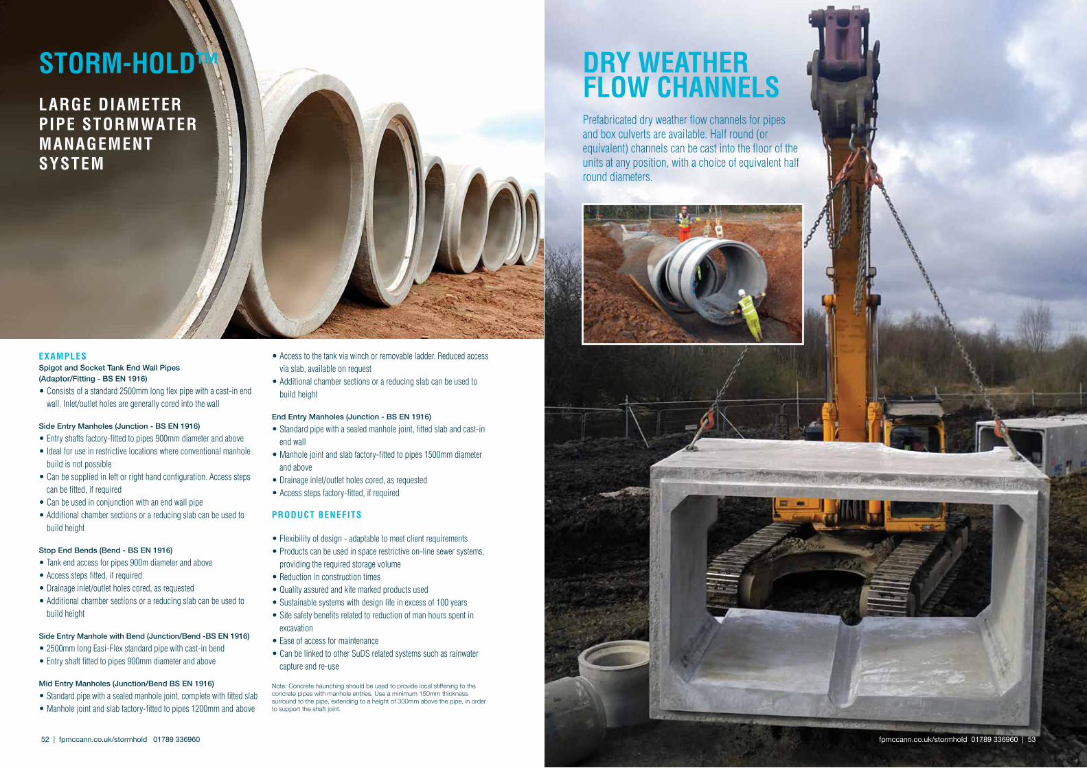
52 | fpmccann.co.uk/stormhold 01789 336960
Prefabricated dry weather flow channels for pipes and box culverts are available. Half round (or equivalent) channels can be cast into the floor of the units at any position, with a choice of equivalent half round diameters.
DRy WEAThER FloW chANNEls
fpmccann.co.uk/stormhold 01789 336960 | 53
ExAMplEsSpigot and Socket Tank End Wall Pipes (Adaptor/Fitting - BS EN 1916)• Consists of a standard 2500mm long flex pipe with a cast-in end wall. Inlet/outlet holes are generally cored into the wall
Side Entry Manholes (Junction - BS EN 1916)• Entry shafts factory-fitted to pipes 900mm diameter and above• Ideal for use in restrictive locations where conventional manhole build is not possible• Can be supplied in left or right hand configuration. Access steps can be fitted, if required• Can be used in conjunction with an end wall pipe • Additional chamber sections or a reducing slab can be used to build height
Stop End Bends (Bend - BS EN 1916)• Tank end access for pipes 900m diameter and above• Access steps fitted, if required• Drainage inlet/outlet holes cored, as requested• Additional chamber sections or a reducing slab can be used to build height
Side Entry Manhole with Bend (Junction/Bend -BS EN 1916)• 2500mm long Easi-Flex standard pipe with cast-in bend• Entry shaft fitted to pipes 900mm diameter and above
Mid Entry Manholes (Junction/Bend BS EN 1916)• Standard pipe with a sealed manhole joint, complete with fitted slab• Manhole joint and slab factory-fitted to pipes 1200mm and above
• Access to the tank via winch or removable ladder. Reduced access via slab, available on request• Additional chamber sections or a reducing slab can be used to build height
End Entry Manholes (Junction - BS EN 1916)• Standard pipe with a sealed manhole joint, fitted slab and cast-in end wall• Manhole joint and slab factory-fitted to pipes 1500mm diameter and above• Drainage inlet/outlet holes cored, as requested• Access steps factory-fitted, if required
pRoDucT bENEFITs
• Flexibility of design - adaptable to meet client requirements• Products can be used in space restrictive on-line sewer systems, providing the required storage volume • Reduction in construction times • Quality assured and kite marked products used• Sustainable systems with design life in excess of 100 years• Site safety benefits related to reduction of man hours spent in excavation• Ease of access for maintenance• Can be linked to other SuDS related systems such as rainwater capture and re-use
Note: Concrete haunching should be used to provide local stiffening to the concrete pipes with manhole entries. Use a minimum 150mm thickness surround to the pipe, extending to a height of 300mm above the pipe, in order to support the shaft joint.
sToRM-holD™lARGE DIAMETER pIpE sToRMWATER MANAGEMENT sysTEM
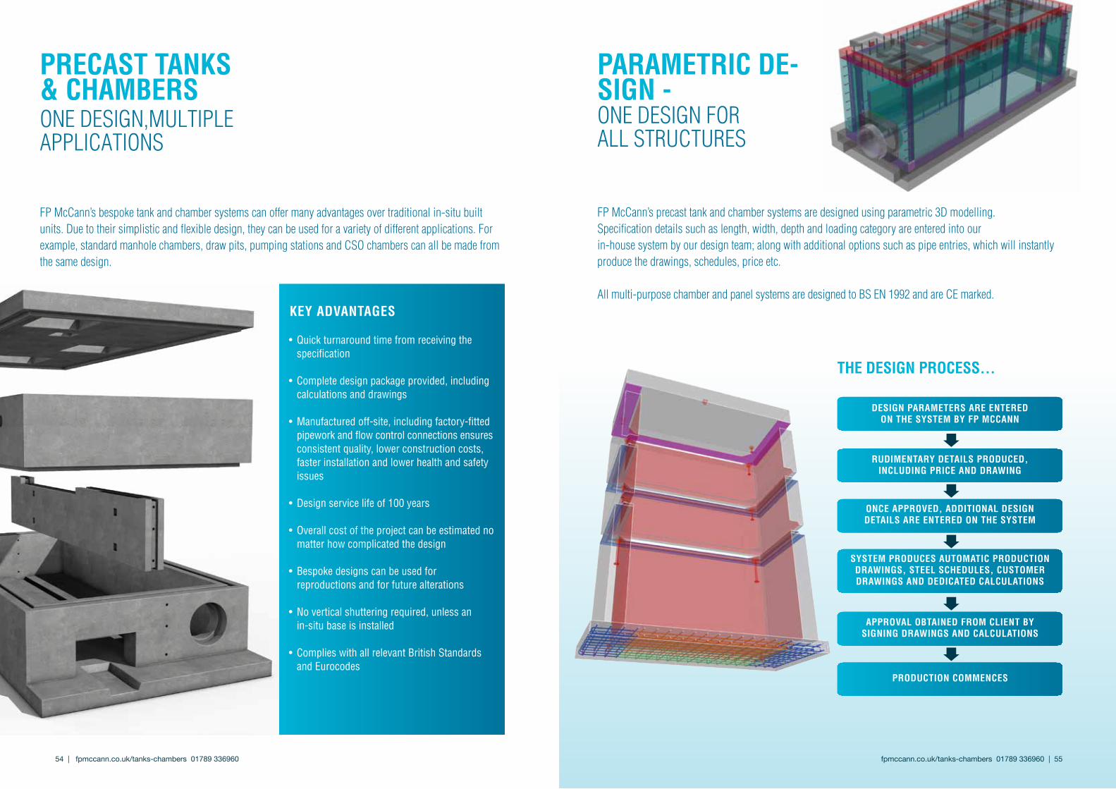
fpmccann.co.uk/tanks-chambers 01789 336960 | 55 54 | fpmccann.co.uk/tanks-chambers 01789 336960
FP McCann’s bespoke tank and chamber systems can offer many advantages over traditional in-situ built units. Due to their simplistic and flexible design, they can be used for a variety of different applications. For example, standard manhole chambers, draw pits, pumping stations and CSO chambers can all be made from the same design.
• Quick turnaround time from receiving the specification
• Complete design package provided, including calculations and drawings
• Manufactured off-site, including factory-fitted pipework and flow control connections ensures
consistent quality, lower construction costs, faster installation and lower health and safety issues
• Design service life of 100 years
• Overall cost of the project can be estimated no matter how complicated the design
• Bespoke designs can be used for reproductions and for future alterations
• No vertical shuttering required, unless an in-situ base is installed
• Complies with all relevant British Standards and Eurocodes
kEy ADvANTAGEs
DEsIGN pARAMETERs ARE ENTERED oN ThE sysTEM by Fp MccANN
oNcE AppRovED, ADDITIoNAl DEsIGN DETAIls ARE ENTERED oN ThE sysTEM
sysTEM pRoDucEs AuToMATIc pRoDucTIoN DRAWINGs, sTEEl schEDulEs, cusToMER DRAWINGs AND DEDIcATED cAlculATIoNs
RuDIMENTARy DETAIls pRoDucED, INcluDING pRIcE AND DRAWING
AppRovAl obTAINED FRoM clIENT by sIGNING DRAWINGs AND cAlculATIoNs
pRoDucTIoN coMMENcEs
FP McCann’s precast tank and chamber systems are designed using parametric 3D modelling. Specification details such as length, width, depth and loading category are entered into our in-house system by our design team; along with additional options such as pipe entries, which will instantly produce the drawings, schedules, price etc.
All multi-purpose chamber and panel systems are designed to BS EN 1992 and are CE marked.
ThE DEsIGN pRocEss...
pARAMETRIc DE-sIGN - ONE DESIGN FOR ALL STRUCTURES
pREcAsT TANks & chAMbERsONE DESIGN,MULTIPLE APPLICATIONS

fpmccann.co.uk/tanks-chambers 01789 336960 | 57 56 | fpmccann.co.uk/tanks-chambers 01789 336960
The multipurpose chamber system is a complete precast unit consisting of a base unit and cover slab and is suitable for a variety of uses, including draw pits, flow controls, penstock or flap valve chambers, CSOs, large storage chambers, overflows, etc.
The length and width of the multipurpose chamber system in-creases in 250mm increments, ranging from 1500 x 1500mm up to a maximum length of 5000 x 3500mm width. The depth of the chamber ranges from 1500mm to 10500mm and it can accom-modate an extensive range of rigid (concrete) and flexible (plastic) pipe entries for various applications.
MulTIpuRposEchAMbERsysTEM
pRoDucT ApplIcATIoNs
• Flow control chambers
• CSO chambers
• Draw pits
• Overflows
• Pumping-stations
• Large manholes
• Clean water storage
• Sludge tanks
• Attenuation tanks
• Basements
DEsIGNED To 3 DIFFERENT loADING cATE-GoRIEs:
• Pedestrian Loading (10kN surcharge)
• Motorway Loading
• Port and Airfield Loading
NB: If different loading is required, please check with a member of staff.
MulTIpuRposE pANEl sysTEMThe multipurpose panel system is an underground structure consisting of an in-situ or precast concrete base, wall panels and cover slab, which is assembled on-site by the contractor or an approved installer using a range of standard jointing types. The panels can be made with cast-in pipe connections, recesses and openings and have penstocks or flap valves pre-installed. Internal weir-walls, overflows, under-passes, baffle walls can also be incorporated into the structure.
This system is suitable for a variety of uses such as CSO cham-bers, storage tanks, large size manholes, pumping stations, valve chambers etc. The main advantage of using this system is that there is no size limitation, except for the height, which cannot exceed six metres, with a two metre overburden. A detailed in-stallation guide is available. Please contact FP McCann for further details.
pRoDucT ApplIcATIoNs
• Air-infiltrationchambers• Flowcontrolchambers• LargeCSOchambers• Waterstoragetanks• Pumpingstations• Attenuationtanks• Largemanholes• ASPstructures• Sludgetanks• Basements• Headwalls
DEsIGNED To 2 DIFFERENT loADING cATEGo-RIEs:
•PedestrianLoading(10kNsurcharge)•LM1MotorwayLoading
NB: If different loading is required, please check with a member of staff.
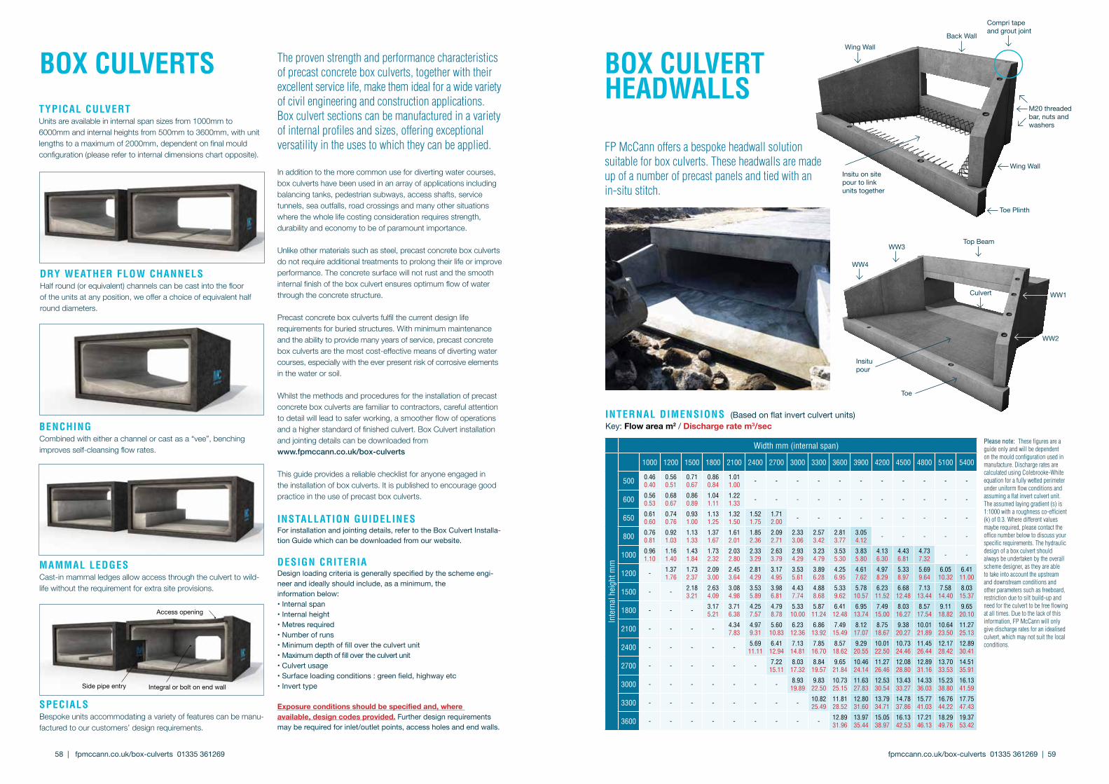
The proven strength and performance characteristics of precast concrete box culverts, together with their excellent service life, make them ideal for a wide variety of civil engineering and construction applications. Box culvert sections can be manufactured in a variety of internal profiles and sizes, offering exceptional versatility in the uses to which they can be applied.
In addition to the more common use for diverting water courses, box culverts have been used in an array of applications including balancing tanks, pedestrian subways, access shafts, service tunnels, sea outfalls, road crossings and many other situations where the whole life costing consideration requires strength, durability and economy to be of paramount importance.
Unlike other materials such as steel, precast concrete box culverts do not require additional treatments to prolong their life or improve performance. The concrete surface will not rust and the smooth internal finish of the box culvert ensures optimum flow of water through the concrete structure.
Precast concrete box culverts fulfil the current design life requirements for buried structures. With minimum maintenance and the ability to provide many years of service, precast concrete box culverts are the most cost -effective means of diverting water courses, especially with the ever present risk of corrosive elements in the water or soil.
Whilst the methods and procedures for the installation of precast concrete box culverts are familiar to contractors, careful attention to detail will lead to safer working, a smoother flow of operations and a higher standard of finished culvert. Box Culvert installation and jointing details can be downloaded from www.fpmccann.co.uk/box-culverts
This guide provides a reliable checklist for anyone engaged in the installation of box culverts. It is published to encourage good practice in the use of precast box culverts.
INsTAllATIoN GuIDElINEsForinstallationandjointingdetails,refertotheBoxCulvert Installa-tion Guide whichcanbedownloadedfromourwebsite.
DEsIGN cRITERIA Designloadingcriteriaisgenerallyspecifiedbytheschemeengi-neerandideallyshouldinclude,asaminimum,theinformationbelow:•Internalspan•Internalheight•Metresrequired•Numberofruns•Minimumdepthoffillovertheculvertunit•Maximumdepthoffillover theculvertunit•Culvertusage•Surface loading conditions:greenfield,highwayetc•Inverttype
exposure conditions should be specified and, where available, design codes provided. Furtherdesignrequirementsmayberequiredforinlet/outletpoints,accessholesandendwalls.
box culvERTs
spEcIAlsBespoke units accommodating a variety of features can be manu-factured to our customers’ design requirements.
Sidepipeentry Integralorboltonendwall
Access opening
bENchING Combined with either a channel or cast as a “vee”, benching improves self-cleansing flow rates.
MAMMAl lEDGEsCast-in mammal ledges allow access through the culvert to wild-life without the requirement for extra site provisions.
DRy WEAThER FloW chANNElsHalf round (or equivalent) channels can be cast into the floor of the units at any position, we offer a choice of equivalent half round diameters.
TypIcAl culvERTUnits are available in internal span sizes from 1000mm to 6000mm and internal heights from 500mm to 3600mm, with unit lengths to a maximum of 2000mm, dependent on final mould configuration (please refer to internal dimensions chart opposite).
INTERNAl DIMENsIoNs (Basedonflatinvertculvertunits)Key:Flow area m2 / Discharge rate m3/sec
Please note: These figures are a guide only and will be dependent on the mould configuration used in manufacture. Discharge rates are calculated using Colebrooke-White equation for a fully wetted perimeter under uniform flow conditions and assuming a flat invert culvert unit. The assumed laying gradient (s) is 1:1000 with a roughness co-efficient (k) of 0.3. Where different values maybe required, please contact the office number below to discuss your specific requirements. The hydraulic design of a box culvert should always be undertaken by the overall scheme designer, as they are able to take into account the upstream and downstream conditions and other parameters such as freeboard, restriction due to silt build-up and need for the culvert to be free flowing at all times. Due to the lack of this information, FP McCann will only give discharge rates for an idealised culvert, which may not suit the local conditions.
Width mm (internal span)
Inte
rnal
hei
ght m
m
1000 1200 1500 1800 2100 2400 2700 3000 3300 3600 3900 4200 4500 4800 5100 5400
500 0.460.40
0.560.51
0.710.67
0.860.84
1.011.00 - - - - - - - - - - -
600 0.560.53
0.680.67
0.860.89
1.041.11
1.221.33 - - - - - - - - - - -
650 0.610.60
0.740.76
0.931.00
1.131.25
1.321.50
1.521.75
1.712.00 - - - - - - - - -
800 0.760.81
0.921.03
1.131.33
1.371.67
1.612.01
1.852.36
2.092.71
2.333.06
2.573.42
2.813.77
3.054.12 - - - - -
1000 0.961.10
1.161.40
1.431.84
1.732.32
2.032.80
2.333.29
2.633.79
2.934.29
3.234.79
3.535.30
3.835.80
4.136.30
4.436.81
4.737.32 - -
1200 - 1.371.76
1.732.37
2.093.00
2.453.64
2.814.29
3.174.95
3.535.61
3.896.28
4.256.95
4.617.62
4.978.29
5.338.97
5.699.64
6.0510.32
6.4111.00
1500 - - 2.183.21
2.634.09
3.084.98
3.535.89
3.986.81
4.437.74
4.888.68
5.339.62
5.7810.57
6.2311.52
6.6812.48
7.1313.44
7.5814.40
8.0315.37
1800 - - - 3.175.21
3.716.38
4.257.57
4.798.78
5.3310.00
5.8711.24
6.4112.48
6.9513.74
7.4915.00
8.0316.27
8.5717.54
9.1118.82
9.6520.10
2100 - - - - 4.347.83
4.979.31
5.6010.83
6.2312.36
6.8613.92
7.4915.49
8.1217.07
8.7518.67
9.3820.27
10.0121.89
10.6423.50
11.2725.13
2400 - - - - - 5.6911.11
6.4112.94
7.1314.81
7.8516.70
8.5718.62
9.2920.55
10.0122.50
10.7324.46
11.4526.44
12.1728.42
12.8930.41
2700 - - - - - - 7.2215.11
8.0317.32
8.8419.57
9.6521.84
10.4624.14
11.2726.46
12.0828.80
12.8931.16
13.7033.53
14.5135.91
3000 - - - - - - - 8.9319.89
9.8322.50
10.7325.15
11.6327.83
12.5330.54
13.4333.27
14.3336.03
15.2338.80
16.1341.59
3300 - - - - - - - - 10.8225.49
11.8128.52
12.8031.60
13.7934.71
14.7837.86
15.7741.03
16.7644.22
17.7547.43
3600 - - - - - - - - - 12.8931.96
13.9735.44
15.0538.97
16.1342.53
17.2146.13
18.2949.76
19.3753.42
box culvERThEADWAlls
FP McCann offers a bespoke headwall solution suitable for box culverts. These headwalls are made up of a number of precast panels and tied with an in-situ stitch.
Wing Wall
Wing Wall
Back Wall
ToePlinth
Insitu on site pour to link unitstogether
Compri tape andgroutjoint
M20threadedbar,nutsandwashers
WW3
WW1
Insitu pour
WW4
Top Beam
Culvert
Toe
WW2
fpmccann.co.uk/box-culverts 01335 361269 | 59 58 | fpmccann.co.uk/box-culverts 01335 361269

MAGhERAFElT16-18 Quarry Road KnockloughrimMagherafelt BT45 8NRT 028 7954 9026 [email protected]
EllIsToWNWhitehill Road Ellistown LeicestershireLE67 1ETT 01530 240000 [email protected]
FpMccANN.co.uk
AGRIculTuRELydney 01594 847500 Magherafelt 028 7954 9026
ARchITEcTuRAl pREcAsTLondon 020 3905 7640
buIlDING pRoDucTsCadeby 01455 290780
box culvERTsWeston Underwood 01335 361269
DRAINAGE Ellistown 01530 240000 (England/Wales) Magherafelt 028 7954 9026 (Scotland/NI)
Dock lEvEllERs Weston Underwood 01335 361269
FENcINGCadeby 01455 290780
FIlTER bED sysTEMsLittleport 01353 861416
FlooRING Weston Underwood 01335 361269 Uddingston 01698 803300
poWER & INFRAsTRucTuRE Cadeby 01455 290780
RAIl Cadeby 01455 290780
spEcIAlIsT pREcAsT Littleport 01353 861416
sTRucTuRAl pREcAsTByley 01606 843500
TANks & chAMbERsWellesbourne 01789 336960
TuNNEls & shAFTs Cadeby 01455 290780
WAllING Lydney 01594 847500 Grantham 01476 562277


