7.0 SMALL GRADE CONTROL STRUCTURES.................................................................. 58 7.1 Small Grade Control Structures .................................................................................... 58
7.1.1 Small Grade Control Structure Selection Process............................................... 60 7.1.2 Grouted Sloping Boulder Grade Control Structure .............................................. 64 7.1.3 Vertical Hard Basin Grade Control Structure....................................................... 71 7.1.4 Sloping Concrete Grade Control Structure .......................................................... 75 7.1.5 Newbury-style Grade Control Structure............................................................... 78 7.1.6 Sculpted Sloping Grade Control Structure........................................................... 83
8.0 EXAMPLES .................................................................................................................... 87 8.1 Example OC-1. Normal Depth Calculation Using the Normal and Critical
Flow Analysis Worksheet............................................................................................... 87 8.2 Example OC-2. Composite Section Calculation Using Design of
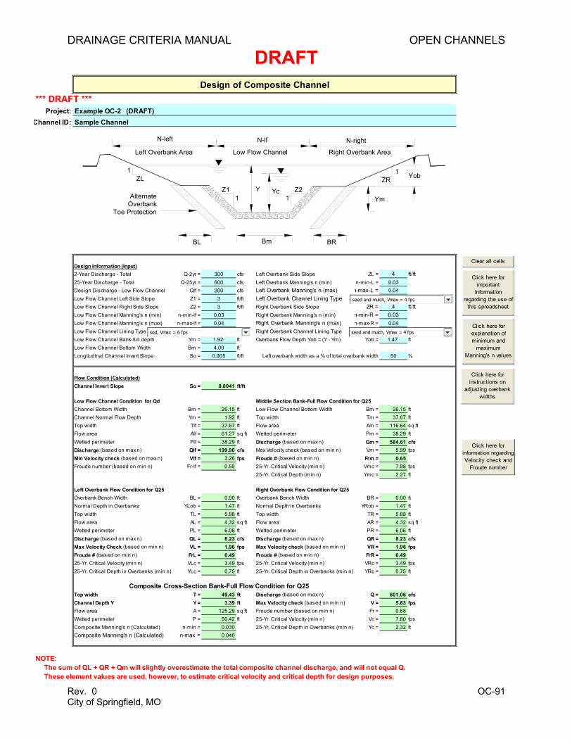
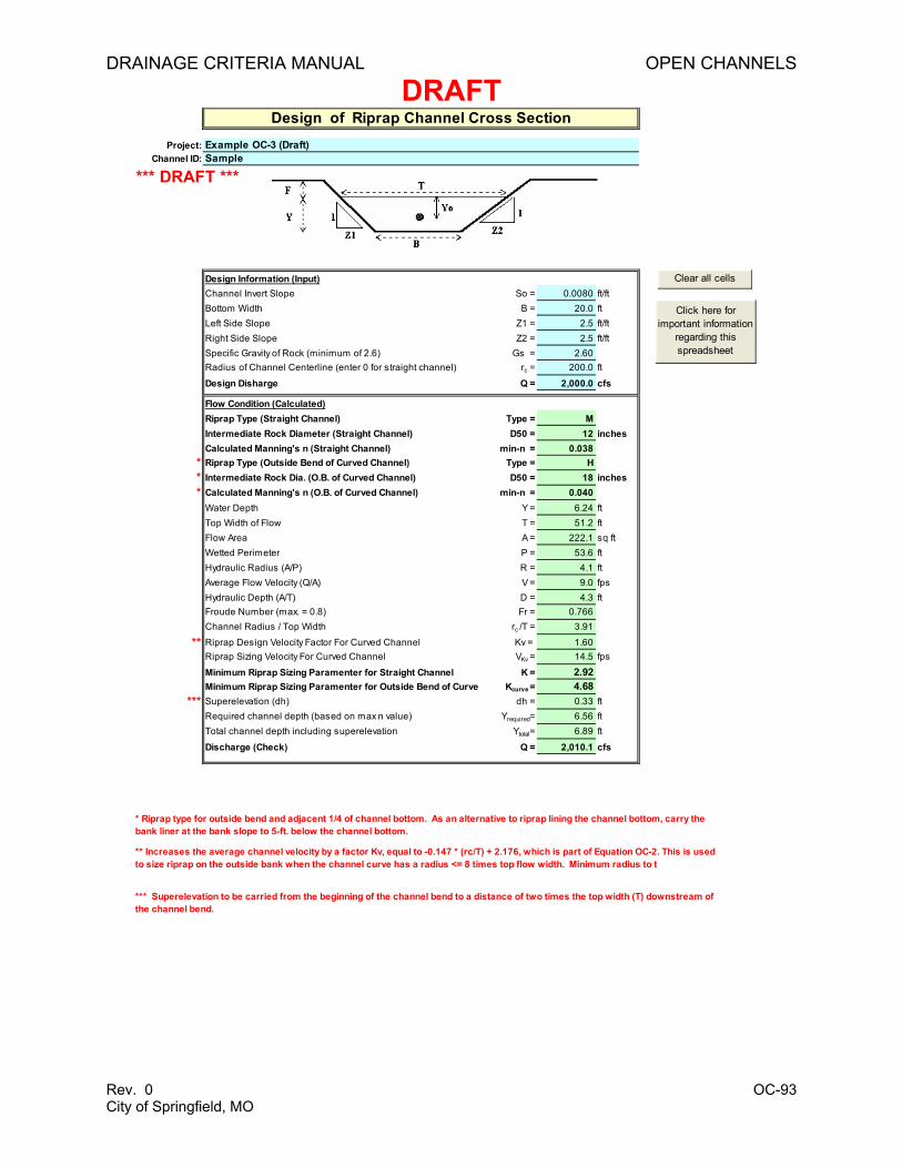
Composite Channel Worksheet..................................................................................... 89 8.3 Example OC-3. Riprap Channel Cross-Section Calculation Using
Design of Riprap Channel Worksheet........................................................................... 92
Table OC-1 Typical Manning’s Roughness Coefficient (n) Values for Open Channels ................19 Table OC-2 Buffer Width Requirements Along Natural Channels .................................................23 Table OC-3 Critical Shear Stresses for Channel Materials (solely for use in channel
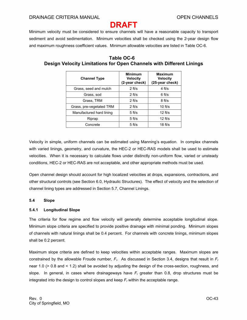
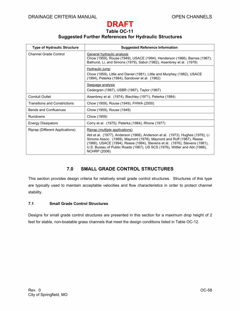
assessments) .............................................................................................................31 Table OC-4 Planform Ratios ..........................................................................................................32 Table OC-5 Channel Condition Scoring Matrix (adapted from Johnson et al. 1999 ) ..................35 Table OC-6 Design Velocity Limitations for Open Channels with Different Linings ......................43 Table OC-7 Riprap Requirements for Channel Linings .................................................................50 Table OC-8 Classification and Gradation of Ordinary Riprap........................................................51 Table OC-9 Classification of Boulders ...........................................................................................51 Table OC-10 Thickness Requirements for Granular Bedding .........................................................52 Table OC-11 Suggested Further References for Hydraulic Structures ...........................................58 Table OC-12 Design Criteria for Small Grade Control Structures ...................................................59 Table OC-13 Summary of Considerations for Selecting Small Grade Control Structure
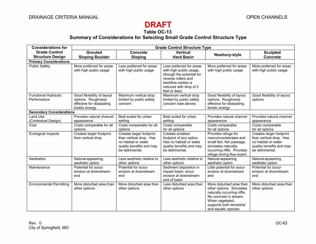
Type............................................................................................................................62 Table OC-14 Summary of Relative Advantages and Disadvantages for Different Types of
Small Grade Control Structures .................................................................................63 Table OC-15 Design Criteria for Grouted Sloping Boulder Grade Control Structure (with
Drop Height 2 Feet or Less) .......................................................................................65 Table OC-16 Design Criteria for Vertical Hard Basin Grade Control Structure (with Drop
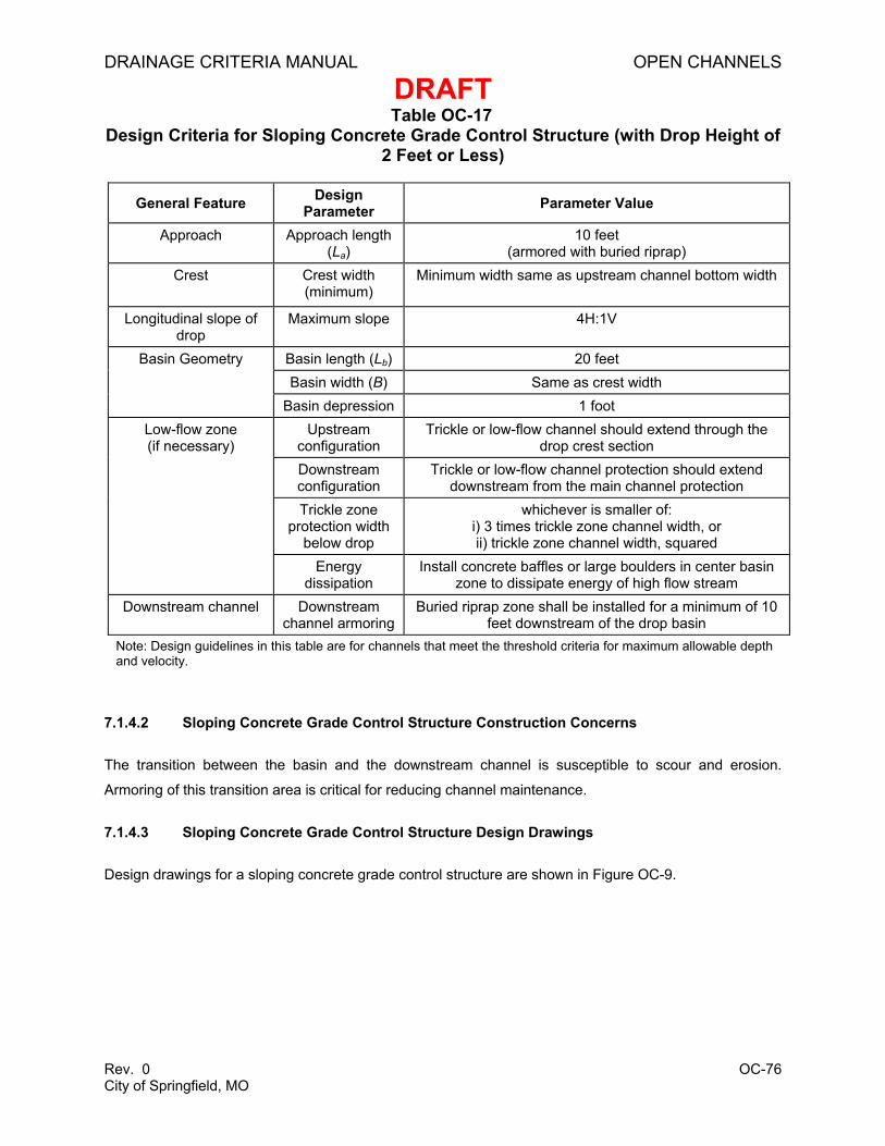
Height of 2 Feet or Less) ............................................................................................72 Table OC-17 Design Criteria for Sloping Concrete Grade Control Structure (with Drop
Height of 2 Feet or Less) ............................................................................................76 Table OC-18 Design Criteria for Newbury Grade Control Structure (with Drop Height 2
Feet or Less) ..............................................................................................................80 Table OC-19 Design Guidelines for Sculpted Sloping Grade Control Structure (with Drop
Height 2 Feet or Less) ................................................................................................84
FIGURES
Figure OC-1 Cross-section of a Two-stage Channel with a Floodplain Internal to the Main Channel ......................................................................................................................15
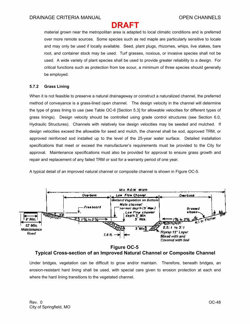
Figure OC-2 Common Features of Stream Geometry ....................................................................26 Figure OC-3 Natural Channel Assessment (Part 1)........................................................................33 Figure OC-4 Natural Channel Assessment (Part 2)........................................................................34 Figure OC-5 Typical Cross-section of an Improved Natural Channel or Composite
Channel ......................................................................................................................48 Figure OC-6 Riprap Channel Side Lining with Toe Protection........................................................53 Figures OC-7a-d Grouted Sloping Boulder Grade Control Structure.....................................................67 Figures OC-8a-b Vertical Hard Basin Grade Control Structure .............................................................73 Figure OC-9 Sloping Concrete Grade Control Structure.................................................................77 Figure OC-10 Newbury Grade Control Structure ..............................................................................82 Figures OC-11a-b Sculpted Sloping Grade Control Structure .................................................................85
DRAINAGE CRITERIA MANUAL OPEN CHANNELS
DRAFT
Rev. 0 OC-1 City of Springfield, MO
1.0 OVERVIEW
1.1 Introduction
Natural and engineered open drainage channels are generally the primary component of the major
conveyance system. The use of open systems and their integration into the existing topography is
strongly preferred to the use of closed or lined systems, and early planning is necessary to accomplish
this objective. When present, natural channels are the preferred system for managing storm water. In
areas of new development and infrastructure improvements, a channel is regarded as natural if it has the
capacity to adjust either its bed or banks in response to changes in flow or sediment load. In areas being
redeveloped, streams that have been previously disturbed are considered natural if they possess a free
boundary capable of adjusting to changes in flow, unless otherwise determined by the Department of
Public Works.
This chapter provides an overview of the open channel planning and design process, including the initial
submittal and permitting steps, types of open channel design options, design principles, design criteria for
both natural and engineered channels, and design steps for different hydraulic structures. Small grade
control structures are addressed in a separate section at the end of the chapter. Design illustrations are
presented at the end of the chapter along with examples to demonstrate the design process. The SF-
Channels Spreadsheet is provided on the CD accompanying this manual to aid in design of open
channels and is used in the examples in this chapter. See Appendix A for a list of the worksheets
provided in this spreadsheet.
1.2 Open Systems Requirements
One of the principles of sound urban storm water management is the practice of preserving floodplains
and natural channels associated with major waterways. In situations where it is not feasible to utilize the
natural system of channels and floodplains, it is preferable for engineered systems to be open and
vegetated where possible, rather than enclosed or concrete lined. The community benefits of this policy
include:
• Improved downstream flood protection due to preservation of naturally occurring floodplain
storage, soil and plant absorption, and reduced velocities
• Protection of upstream reaches from accelerated erosion caused by actions in adjacent reaches.
• Enhanced water quality
• Improved public safety
• Generally lower construction cost than hard improvements
DRAINAGE CRITERIA MANUAL OPEN CHANNELS
DRAFT
Rev. 0 OC-2 City of Springfield, MO
• More aesthetic value to neighborhood and community
• More open space
• Recreational opportunities for neighborhood and community
• Improved habitat and biodiversity
• Lower long-term maintenance costs
• Generally enhanced flood control that exceeds design storm requirements due to wide and
shallow geometry
1.3 Planning for Open Channels
When planning for open channels to serve a development, many important factors must be considered,
such as:
• Public safety
• Permitting
• Cost, including capital expenses, operations, maintenance, and replacement
• Right of way, access and existing utilities
• Protection of existing natural channels and their riparian corridors
• The engineered channel and drainage easement for the design storm under full watershed
development conditions and maximum potential peak flow
• Sediment budgets, including conditions with upstream construction activity and providing for
sediment transport competency1
• Watershed or development master plans
• Existing or anticipated stream instabilities or meandering, particularly at the interface between
natural and engineered channels
• Appearance
1 Sediment transport competency – the ability of the channel to carry the sediment delivered to it without degrading or aggrading the channel bed.
DRAINAGE CRITERIA MANUAL OPEN CHANNELS
DRAFT
Rev. 0 OC-3 City of Springfield, MO
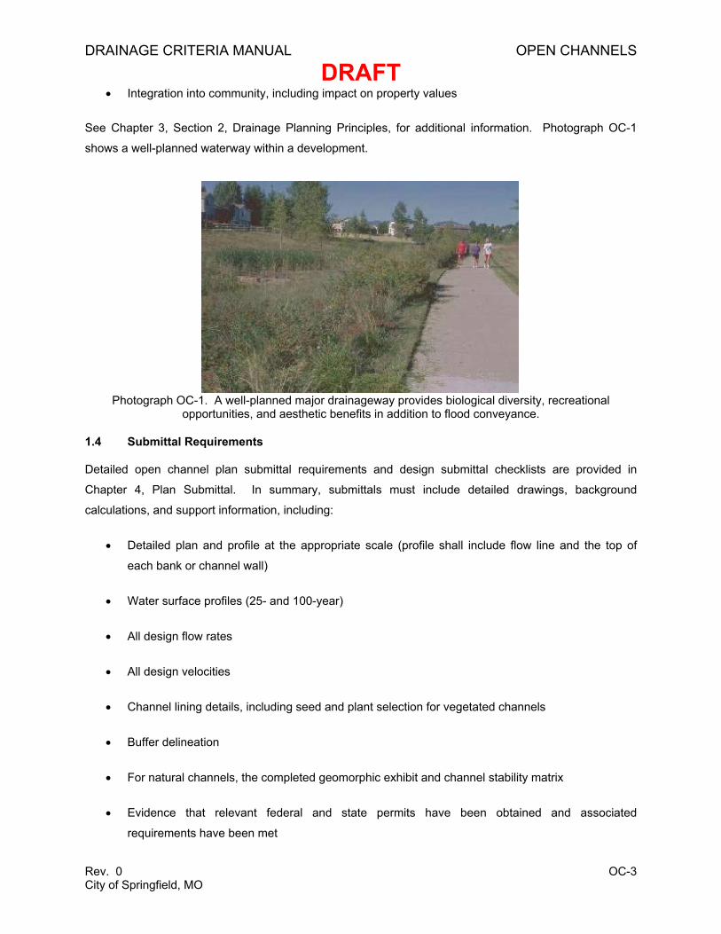
• Integration into community, including impact on property values
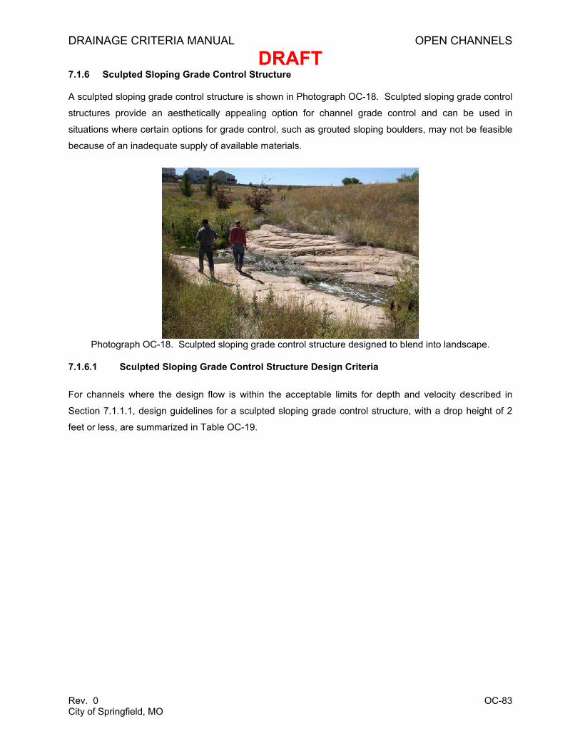
See Chapter 3, Section 2, Drainage Planning Principles, for additional information. Photograph OC-1
shows a well-planned waterway within a development.
Photograph OC-1. A well-planned major drainageway provides biological diversity, recreational opportunities, and aesthetic benefits in addition to flood conveyance.
1.4 Submittal Requirements
Detailed open channel plan submittal requirements and design submittal checklists are provided in
Chapter 4, Plan Submittal. In summary, submittals must include detailed drawings, background
calculations, and support information, including:
• Detailed plan and profile at the appropriate scale (profile shall include flow line and the top of
each bank or channel wall)
• Water surface profiles (25- and 100-year)
• All design flow rates
• All design velocities
• Channel lining details, including seed and plant selection for vegetated channels
• Buffer delineation
• For natural channels, the completed geomorphic exhibit and channel stability matrix
• Evidence that relevant federal and state permits have been obtained and associated
requirements have been met
DRAINAGE CRITERIA MANUAL OPEN CHANNELS
DRAFT
Rev. 0 OC-4 City of Springfield, MO
Water surface profiles shall be calculated using open channel methods discussed in this chapter and
backwater calculation methods found in Chapter 7, Bridges and Culverts.
1.5 Permits
Construction involving major drainageways typically requires several federal, state, and local permits.
See Chapter 3, Section 2.6, Required Permits, for more information. Early up-front planning for federal
permits from the Federal Emergency Management Agency (FEMA) and the U.S. Army Corps of
Engineers (USACE) is particularly relevant for open channels.
All documentation of correspondence with USACE must be provided to the City prior to approval of
construction plans, regardless of whether the project is within USACE jurisdiction. All necessary federal
permits to begin construction must be obtained and provided to the City prior to approval by the City to
begin construction. It is the applicants’ responsibility to obtain and comply with all relevant permits.
The USACE Section 404 permitting process typically requires mitigation for impacted wetlands and may
require the preservation of certain aspects of existing natural channels. In cases where existing wetlands
are eliminated or otherwise damaged, wetland mitigation may be required. In addition to any federal
requirements, the City requires that all mitigation be completed on site.
1.6 Maintenance
All major drainageways and open channels shall be designed to allow regular maintenance. The
designer shall consider access requirements for equipment necessary to maintain or replace walls,
boulders, concrete mats, gabions, turf reinforcement mats (TRMs), etc. The responsible party must be
financially and technically capable of providing long-term maintenance of facilities, including those that
utilize concrete, grass or other bioengineered configuration. Additional information regarding
maintenance can be found in Chapter 12, Easements and Maintenance.
1.7 Safety
Public safety shall be the paramount consideration when designing open channel systems.
Representative issues that must be considered include channel configurations that limit the risk of a fall
into the channel and channel hydraulic designs that minimize the risk of hazardous conditions, such as
“reverse rollers” that can entrap a person downstream from a low head dam. All vertical walls greater
than 3 feet in height shall have a safety fence or handrail if the wall is located where the public may be in
close proximity. Warning signs may be necessary in areas with high risk. Channels that do not have
vertical walls shall be designed with side slopes no greater than 3H:1V to allow for safe exit from the
channel. All slopes that are to be maintained by motorized mowers shall be graded at a minimum of
3H:1V. Slopes of 4H:1V are preferred for safety and aesthetic reasons.
DRAINAGE CRITERIA MANUAL OPEN CHANNELS
DRAFT
Rev. 0 OC-5 City of Springfield, MO
2.0 TYPES OF OPEN CHANNELS
This manual addresses two basic channel types: natural and engineered. Natural channels are
drainageways initially formed by nature and are capable of adjusting their bed and banks in response to
changes in flows or sediment delivery. Engineered channels, in contrast, do not adjust to changing
conditions in the same manner as natural channels. Types of engineered channels include, in order of
preference: naturalized, vegetated, channels with manufactured linings, riprap-lined, and concrete-lined.
Engineered channels can take various forms such as single-stage, two-stage, and channels with
composite materials. The most commonly used types of engineered channels are addressed in Section
2.2, and different channel forms are discussed in Section 2.3. Standard design details can be found in
the City of Springfield, Missouri, Design Standards for Public Improvements (Design Standards). Prior to
choosing channel types in new developments, the designer shall consult with the City regarding master
plans, regulations, and other constraints to assist in a sound and acceptable design. This is imperative
so that preliminary layouts and space allocations will be adequate for drainage.
2.1 Natural Channels
Natural channels, as implied, are drainageways formed by nature. These channels exist in a state of
dynamic equilibrium and have the inherent ability to adjust their bed or banks in response to changes in
flow or sediment load. Natural channels also exist in constant interaction with their bordering vegetation.
It is the ability of natural channels to self-manage that distinguishes natural channels from engineered
channels and requires distinctly different management criteria. The ability to self-form and self-manage
renders natural channels as the most efficient type of drainageway. It is difficult, if not impossible, to
replicate all natural channel attributes in an artificial channel. For this reason, the City chooses to leave
natural channels and adjacent riparian vegetation intact whenever feasible. Specific design criteria and
guidelines for natural channels are provided in Section 4.0.
DRAINAGE CRITERIA MANUAL OPEN CHANNELS
DRAFT
Rev. 0 OC-6 City of Springfield, MO
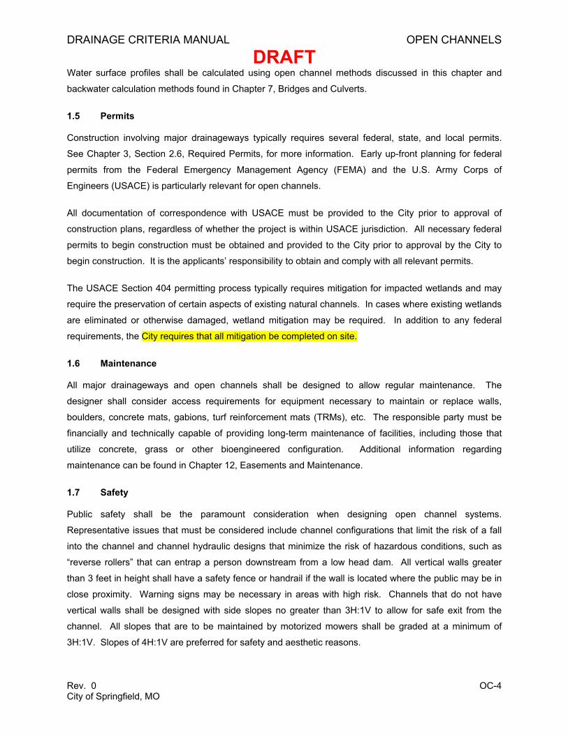
Photograph OC-2. Stable natural channel with riparian buffer.
2.2 Engineered Channels
Where an engineered channel is the preferred option, the choice of channel type and alignment must
consider a variety of multi-disciplinary factors, including:
• The influence of channel alterations on the stability and ecological integrity of the adjacent
unaltered reaches.
• Hydraulic considerations such as existing and future design flows and velocities, channel slope,
available right-of-way, site topography, upstream and downstream conditions, and basin
sediment yield.
• Structural considerations such as seepage and uplift forces, anticipated shear stresses, and
adjacent loads, such as buildings.
• Environmental considerations such as municipal, county, state, or federal requirements, riparian
zones, adjacent environmental hazards, existing perennial streams and wetlands, existing
habitat, and wildlife and watershed objectives.
• Sociological considerations such as neighborhood character, street and traffic patterns,
neighborhood social issues, public safety, pedestrian and bicycle traffic, recreational needs, and
right-of-way corridor needs.
• Practical considerations such as cost, availability of material, and areas for wasting fill.
• Maintenance considerations such as life expectancy, repair and reconstruction needs, regular
maintenance needs, proven performance, accessibility, and regulatory constraints to
maintenance.
DRAINAGE CRITERIA MANUAL OPEN CHANNELS
DRAFT
Rev. 0 OC-7 City of Springfield, MO
The primary engineered channel types are described below in Sections 2.2.1 through 2.2.6. Specific
design criteria and guidelines for engineered channels are provided in Section 5.0.
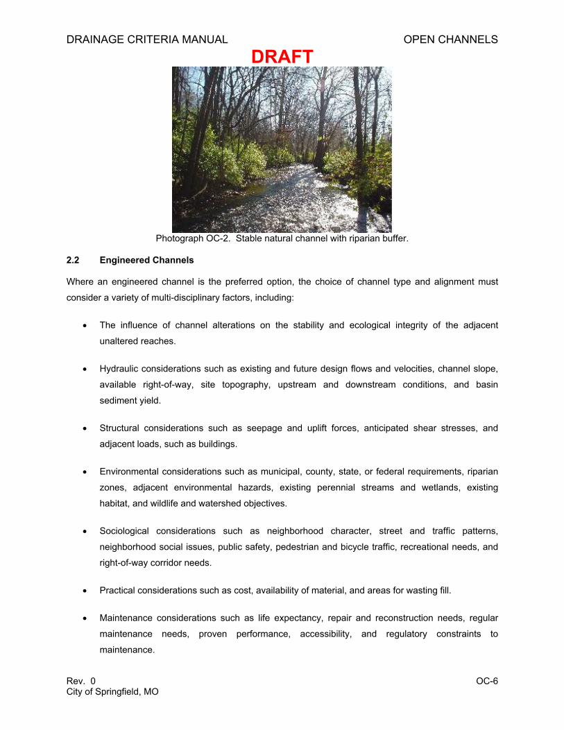
2.2.1 Naturalized Channels
Naturalized channels are previously manipulated channels that are restored to some degree of natural
form, process, and function. Naturalized channels are not completely natural. Stream restoration,
reclamation, and rehabilitation are all terms commonly used to describe the process of naturalizing a
channel. In disturbed urban systems, complete restoration is not achievable; however, many of the
physical processes associated with natural flows of water and sediment can be approximated and the
ecological functions improved compared to purely artificial channels.
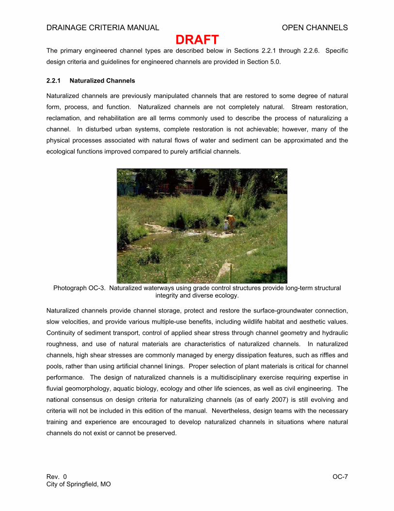
Photograph OC-3. Naturalized waterways using grade control structures provide long-term structural integrity and diverse ecology.
Naturalized channels provide channel storage, protect and restore the surface-groundwater connection,
slow velocities, and provide various multiple-use benefits, including wildlife habitat and aesthetic values.
Continuity of sediment transport, control of applied shear stress through channel geometry and hydraulic
roughness, and use of natural materials are characteristics of naturalized channels. In naturalized
channels, high shear stresses are commonly managed by energy dissipation features, such as riffles and
pools, rather than using artificial channel linings. Proper selection of plant materials is critical for channel
performance. The design of naturalized channels is a multidisciplinary exercise requiring expertise in
fluvial geomorphology, aquatic biology, ecology and other life sciences, as well as civil engineering. The
national consensus on design criteria for naturalizing channels (as of early 2007) is still evolving and
criteria will not be included in this edition of the manual. Nevertheless, design teams with the necessary
training and experience are encouraged to develop naturalized channels in situations where natural
channels do not exist or cannot be preserved.
DRAINAGE CRITERIA MANUAL OPEN CHANNELS
DRAFT
Rev. 0 OC-8 City of Springfield, MO
2.2.2 Vegetated Channels
Vegetated channels lined with turf grass or native plants are traditional engineered channels with a
vegetative lining. These channels are distinct from naturalized channels although both incorporate
vegetated linings. Geomorphic principles of river process and function, as well as most life sciences, play
a much smaller role in the design of vegetated channels than in naturalized channels. Vegetated
channels can provide channel storage, reduced velocities and shear stresses, aesthetically pleasing open
spaces, and various multiple use benefits. Vegetated channels in urbanizing watersheds may require
grade control structures to reduce velocities and prevent degradation of the vegetative liner. Low-flow
areas may need to be armored or otherwise stabilized to prevent erosion.
More stable and attractive facilities are typically achieved when sod or plant plugs are used rather than
seed and mulch, particularly in the lower part of the channel that is inundated more often. The choice of
vegetation is dependent on the frequency, depth and duration of inundation as well as water quality,
habitat, and aesthetic considerations. Some settings require a highly groomed, manicured look where
turf grass is desirable. However, traditional turf is energy intensive and requires frequent mowing,
irrigation and fertilizing, which may adversely affect water quality. Alternative turf types such as low-
maintenance fescue or buffalo grass provide the benefits of conventional turf with less maintenance.
When the channel bed is likely to be inundated for more than 12 to 24 hours during frequent rain events,
the designer should consider inundation-tolerant sedges and rushes for the bed and grasses for the
slopes.
Where a manicured appearance is less of a requirement, the channel vegetation can include a more
diverse selection of forbs, native grasses, and small shrubs. In all cases, the hydraulic roughness of the
lining is an important part of the design. Although certain types of vegetation, such as shrubs, increase
roughness and reduce channel capacity more than other types, designers are encouraged to account for
the higher roughness and use it as a design element. For example, increased hydraulic roughness can
be designed to direct scouring flows away from the toe of a slope and toward the channel centerline to
reduce the risk of erosion. The roughness of the vegetation throughout its life cycle must be considered
as well as the influence of roughness on channel capacity. In addition to stabilizing the channel, a
diverse plant palette of native vegetation provides water quality benefits, desirable habitat and aesthetic
benefits. Photograph OC-4 shows an attractive grass-lined channel.
DRAINAGE CRITERIA MANUAL OPEN CHANNELS
DRAFT
Rev. 0 OC-9 City of Springfield, MO
Photograph OC-4. Engineered grass-lined drainageway with rock lined low-flow channel, natural components and community recreation uses.
2.2.3 Channels with Manufactured Liners
Conditions may exist where a vegetated channel is desirable, but flows and velocities exceed the
allowable conditions for a vegetated channel without reinforcement. The designer should consider
reducing the applied stress by increasing hydraulic roughness in the channel, including energy dissipation
structures, or adjusting channel geometry, as well as lining materials. Often, by applying these
measures, the applied stress can be reduced to a degree that significantly reduces or eliminates the need
for channel lining.
When flow conditions still exceed allowable conditions for vegetated channels, a manufactured liner may
be appropriate. It may only be necessary to use these liners in the channel bed and lower banks. Liners
can provide some of the benefits of vegetated channels, while remaining stable under high velocity
mats, modular blocks, reinforced sod, and various types of permanent TRMs. These liners are often
proprietary, and new products are continually being introduced. Each type of channel lining must be
scrutinized for its merits, applicability, ability to meet other community needs, long-term integrity,
maintenance needs, and costs. Specific design criteria for manufactured liners are provided in Section
5.7.
When considering gabions, it is especially important to evaluate the right-of-way constraints and costs of
replacement. If there is a possibility that the bed could degrade, gabions shall not be used to line channel
banks because of the high risk of gabion collapse, rupture or toppling.
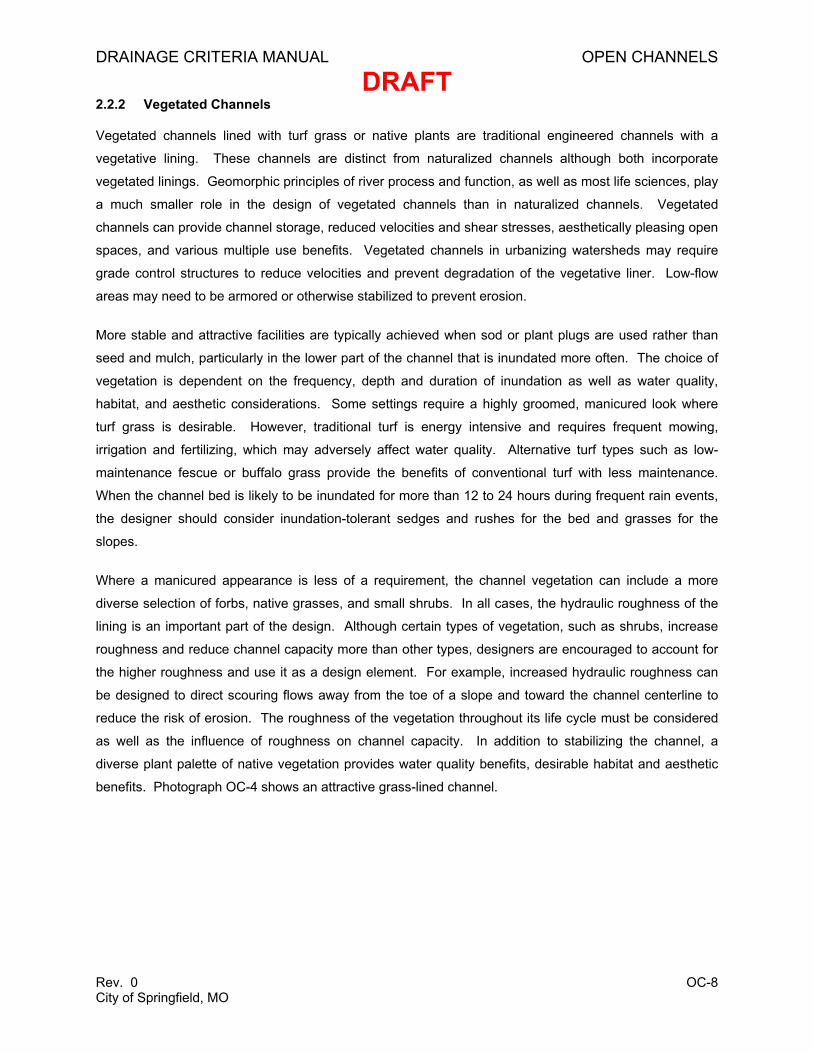
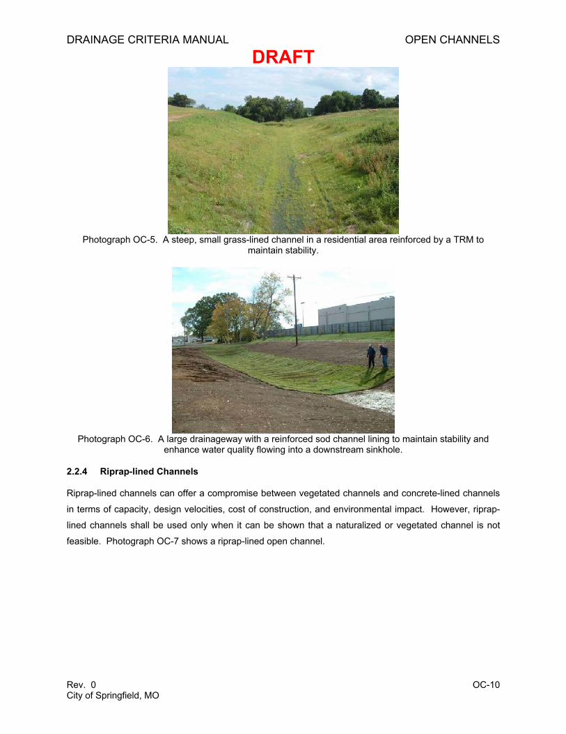
Photograph OC-5 shows a small, steep grass channel lined with a TRM to maintain stability. Photograph
OC-6 shows a large drainageway lined with reinforced sod.
DRAINAGE CRITERIA MANUAL OPEN CHANNELS
DRAFT
Rev. 0 OC-10 City of Springfield, MO
Photograph OC-5. A steep, small grass-lined channel in a residential area reinforced by a TRM to maintain stability.
Photograph OC-6. A large drainageway with a reinforced sod channel lining to maintain stability and enhance water quality flowing into a downstream sinkhole.
2.2.4 Riprap-lined Channels
Riprap-lined channels can offer a compromise between vegetated channels and concrete-lined channels
in terms of capacity, design velocities, cost of construction, and environmental impact. However, riprap-
lined channels shall be used only when it can be shown that a naturalized or vegetated channel is not
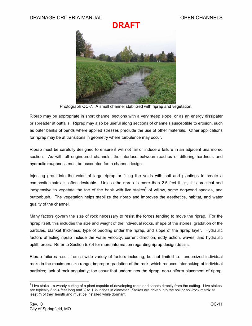
feasible. Photograph OC-7 shows a riprap-lined open channel.
DRAINAGE CRITERIA MANUAL OPEN CHANNELS
DRAFT
Rev. 0 OC-11 City of Springfield, MO
Photograph OC-7. A small channel stabilized with riprap and vegetation.
Riprap may be appropriate in short channel sections with a very steep slope, or as an energy dissipater
or spreader at outfalls. Riprap may also be useful along sections of channels susceptible to erosion, such
as outer banks of bends where applied stresses preclude the use of other materials. Other applications
for riprap may be at transitions in geometry where turbulence may occur.
Riprap must be carefully designed to ensure it will not fail or induce a failure in an adjacent unarmored
section. As with all engineered channels, the interface between reaches of differing hardness and
hydraulic roughness must be accounted for in channel design.
Injecting grout into the voids of large riprap or filling the voids with soil and plantings to create a
composite matrix is often desirable. Unless the riprap is more than 2.5 feet thick, it is practical and
inexpensive to vegetate the toe of the bank with live stakes2 of willow, some dogwood species, and
buttonbush. The vegetation helps stabilize the riprap and improves the aesthetics, habitat, and water
quality of the channel.
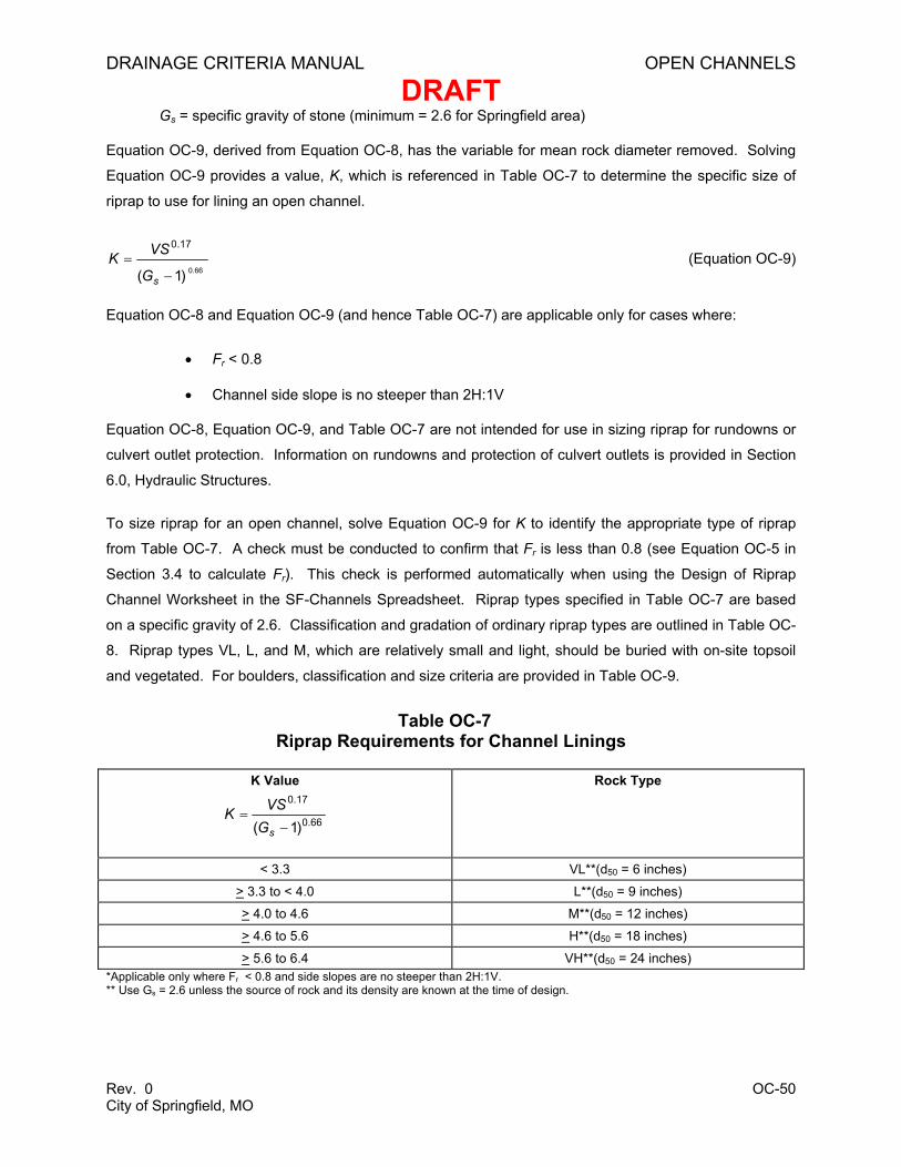
Many factors govern the size of rock necessary to resist the forces tending to move the riprap. For the
riprap itself, this includes the size and weight of the individual rocks, shape of the stones, gradation of the
particles, blanket thickness, type of bedding under the riprap, and slope of the riprap layer. Hydraulic
factors affecting riprap include the water velocity, current direction, eddy action, waves, and hydraulic
uplift forces. Refer to Section 5.7.4 for more information regarding riprap design details.
Riprap failures result from a wide variety of factors including, but not limited to: undersized individual
rocks in the maximum size range; improper gradation of the rock, which reduces interlocking of individual
particles; lack of rock angularity; toe scour that undermines the riprap; non-uniform placement of riprap,
2 Live stake – a woody cutting of a plant capable of developing roots and shoots directly from the cutting. Live stakes are typically 3 to 4 feet long and ½ to 1 ½ inches in diameter. Stakes are driven into the soil or soil/rock matrix at least ¾ of their length and must be installed while dormant.
DRAINAGE CRITERIA MANUAL OPEN CHANNELS
DRAFT
Rev. 0 OC-12 City of Springfield, MO
with windows of undersized or gap-grade rock; flat and elongated rocks that do not interlock; settlement
of sub-grade; geotechnical failures; ice and debris impacts; failure of filter fabric resulting from poor
installation; failure to consider stress concentrators, such as curvature and contraction of the channel;
and improper bedding for the riprap, which allows leaching of channel particles through the riprap blanket.
Suggested reading regarding riprap design is provided in Section 6.0, Hydraulic Structures.
2.2.5 Grouted Boulder Channels
If properly designed and constructed, a grouted boulder channel can provide the appearance of a natural
channel with rock outcroppings and can be an aesthetically pleasing option to concrete and riprap
channels. Grouted boulder channels are particularly useful for lining low-flow channels and steep banks.
A grouted boulder channel is shown in Photograph OC-8.
Photograph OC-8. Grouted boulder channel and drop structures.
Grouted boulders provide a relatively impervious channel lining which is less subject to vandalism than
ordinary riprap and which requires less routine maintenance because of reduced silt and trash
accumulation. The appearance of grouted boulders is enhanced by exposing the tops of individual
stones and by cleaning the projecting rocks with a wet broom immediately after the grouting operation. It
is also recommended that grouted boulders on channel banks and outside of frequent flow areas be at
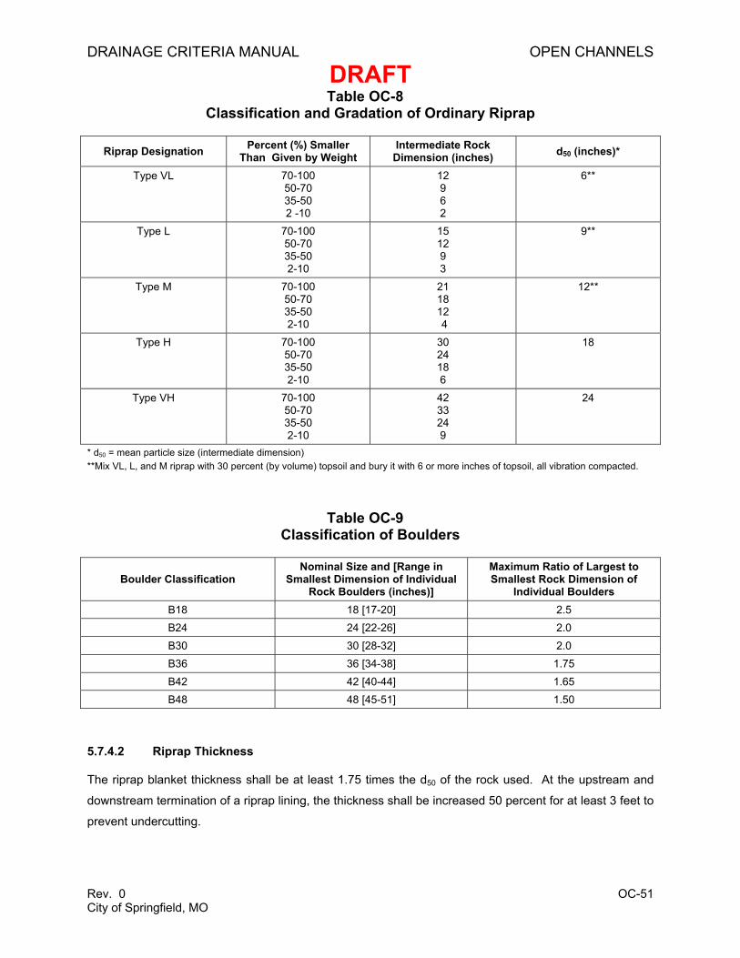
least partly buried with topsoil and revegetated. Boulders used for riprap shall meet all the properties of
rock for ordinary riprap, and rock of uniform size shall be used. Rock properties are discussed in Section
5.7.4.1, Rock Sizing.
2.2.6 Concrete-lined Channels
Concrete-lined channels are generally discouraged due to safety, aesthetic and long-term maintenance
issues, as well as negative impacts on habitat and water quality. In new developments, concrete
channels will not be permitted unless it is shown that channel options utilizing more natural materials are
not feasible. In general, proper planning will avoid the need for concrete-lined channels, though in certain
DRAINAGE CRITERIA MANUAL OPEN CHANNELS
DRAFT
Rev. 0 OC-13 City of Springfield, MO
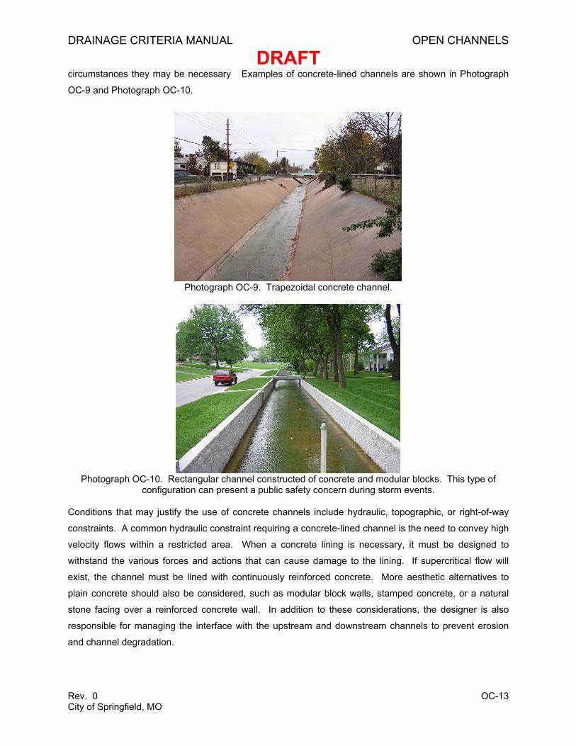
circumstances they may be necessary Examples of concrete-lined channels are shown in Photograph
OC-9 and Photograph OC-10.
Photograph OC-9. Trapezoidal concrete channel.
Photograph OC-10. Rectangular channel constructed of concrete and modular blocks. This type of configuration can present a public safety concern during storm events.
Conditions that may justify the use of concrete channels include hydraulic, topographic, or right-of-way
constraints. A common hydraulic constraint requiring a concrete-lined channel is the need to convey high
velocity flows within a restricted area. When a concrete lining is necessary, it must be designed to
withstand the various forces and actions that can cause damage to the lining. If supercritical flow will
exist, the channel must be lined with continuously reinforced concrete. More aesthetic alternatives to
plain concrete should also be considered, such as modular block walls, stamped concrete, or a natural
stone facing over a reinforced concrete wall. In addition to these considerations, the designer is also
responsible for managing the interface with the upstream and downstream channels to prevent erosion
and channel degradation.
DRAINAGE CRITERIA MANUAL OPEN CHANNELS
DRAFT
Rev. 0 OC-14 City of Springfield, MO
2.3 Channel Forms
In contrast to the discussions of specific channel types in Sections 2.2.1 through 2.2.6, this section
addresses the broader issues of different channel cross-section forms and the application of different
channel linings within the cross-section.
2.3.1 Two-stage Channels
Many natural channels maintain a two-stage cross-section, particularly at meanders. A two-stage cross-
section is an efficient way to manage energy and prevent rapid or excessive channel adjustment.
Typically, the lower stage conveys the base flow up to a discharge rate referred to as the channel forming
or bank-full discharge flow. The channel forming flow is that which, over time, has the greatest influence
on channel size and shape. In undisturbed settings, this flow generally corresponds to the 1.5- to 2-year
recurrence interval. At this stage, natural channels often form an internal floodplain to reduce stress
associated with higher flows (see Figure OC-1). Internal floodplains are depositional features in a natural
channel.
In disturbed urban systems with poor hydrologic control, the channel forming discharge may occur many
times in a year. The drastically increased frequency of the channel forming flow is a major reason for the
poor condition of many urban channels.
Designers of engineered channels may use the two-stage approach as well. The lower channel shall be
sized to accommodate the channel forming flow, while the larger channel may be sized to accommodate
the desired design flow. Increasing the dimensions of the low-flow channel in an attempt to increase
channel capacity is counterproductive for flood control and destructive of the water resource. When the
channel is over-widened, the hydraulic slope effectively increases and the shear stress applied to the
channel increases commensurately. Incision, or downcutting of the bed, then advances upstream,
liberating sediment which deposits in the over-widened reach. When the over-widening is associated with
a culvert or bridge, the sediment commonly deposits and consolidates in or immediately upstream of the
culvert or bridge bay and reduces the capacity. Attempts to “maintain” the capacity by periodic sediment
removal simply induce a new wave of incision and deposition.
DRAINAGE CRITERIA MANUAL OPEN CHANNELS
DRAFT
Rev. 0 OC-15 City of Springfield, MO
Figure OC-1 Cross-section of a Two-stage Channel with a Floodplain Internal to the Main
Channel
Where the engineered channel will interface with a natural channel, it is extremely important to avoid
over-widening the low-flow channel. By setting a channel width greater than the natural low-flow width,
the designer may induce a draw-down curve upstream and induce incision or bank scour in the upstream
channel. In addition to damaging the upstream reach, the liberated sediment will be deposited in the
over-widened area downstream and may decrease needed flood capacity. Guidance on sizing a low-flow
channel is provided in Section 5.9.
It is important to note that many two-stage channels do not maintain a two-stage cross-section throughout
their length. Typically, the internal floodplain occurs at the inside of a meander and may decrease or
disappear altogether in straight runs or transition points. Internal floodplains rarely occur on the outside
of meanders.
Some geologically young channels, highly disturbed urban channels, or those dominated by gravel or
bedrock may not form two-stage channels. If interfacing with a natural single-stage channel, it is
reasonable to design a single-stage engineered channel, provided that the base width does not exceed
that of the natural channel.
BaseflowInternal Floodplain
Bank-full Width
DRAINAGE CRITERIA MANUAL OPEN CHANNELS
DRAFT
Rev. 0 OC-16 City of Springfield, MO
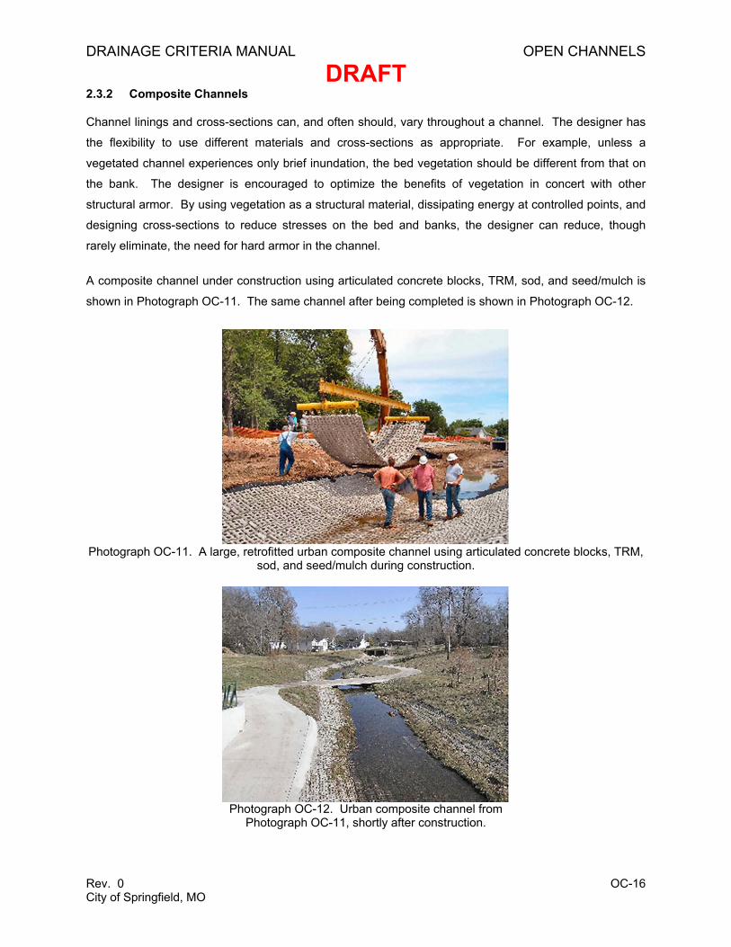
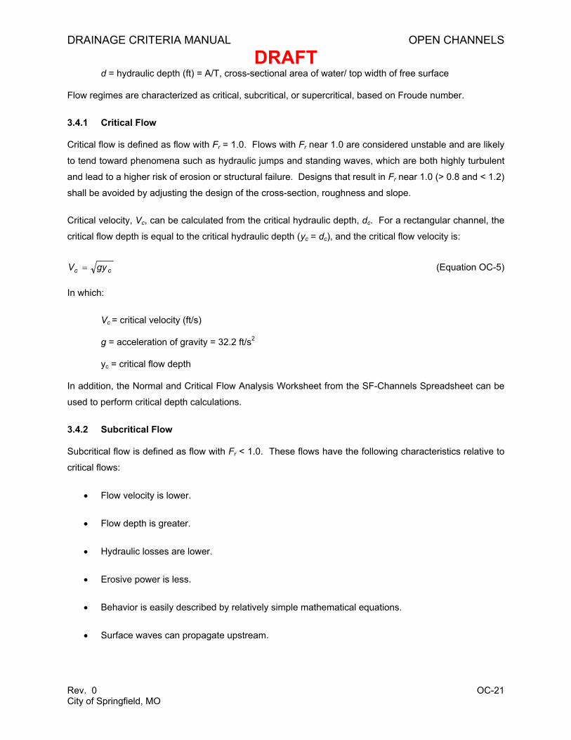
2.3.2 Composite Channels
Channel linings and cross-sections can, and often should, vary throughout a channel. The designer has
the flexibility to use different materials and cross-sections as appropriate. For example, unless a
vegetated channel experiences only brief inundation, the bed vegetation should be different from that on
the bank. The designer is encouraged to optimize the benefits of vegetation in concert with other
structural armor. By using vegetation as a structural material, dissipating energy at controlled points, and
designing cross-sections to reduce stresses on the bed and banks, the designer can reduce, though
rarely eliminate, the need for hard armor in the channel.
A composite channel under construction using articulated concrete blocks, TRM, sod, and seed/mulch is
shown in Photograph OC-11. The same channel after being completed is shown in Photograph OC-12.
Photograph OC-11. A large, retrofitted urban composite channel using articulated concrete blocks, TRM, sod, and seed/mulch during construction.
Photograph OC-12. Urban composite channel from Photograph OC-11, shortly after construction.
DRAINAGE CRITERIA MANUAL OPEN CHANNELS
DRAFT
Rev. 0 OC-17 City of Springfield, MO
3.0 OPEN CHANNEL DESIGN PRINCIPLES
Standard open channel analysis and design is based on fundamental assumptions of flow types and flow
regimes. A brief discussion of these assumptions is provided to assist the designer in determining
whether actual site conditions conform to these fundamental assumptions. Determining this requires
knowledge of open channel hydraulic principles and requires background and references beyond the
scope of this manual. The City assumes that designers have appropriate background in open channel
hydraulics and design and are registered professional engineers.
3.1 Types of Flow
Open channel flow commonly characterized according to variability with respect to time and space using
the following terms:
• Steady flow—conditions at any point in a stream remain constant with respect to time (Daugherty
and Franzini 1977).
• Unsteady flow—flow conditions (e.g., depth) vary with time.
• Uniform flow—the magnitude and direction of velocity in a stream are the same at all points in the
stream at a given time (Daugherty and Franzini 1977). If a channel is uniform and resistance and
gravity forces are in exact balance, the water surface will be parallel to the bottom of the channel
for uniform flow.
• Varied flow—discharge, depth, or other characteristics of the flow change along the course of the
stream. For a steady flow condition, flow is termed rapidly varied if these characteristics change
over a short distance. If characteristics change over a longer stretch of the channel for steady
flow conditions, flow is termed gradually varied.
For the purposes of open channel design, flow is usually considered steady and uniform. For a channel
with a given roughness, discharge, and slope, there is only one possible depth for maintaining a uniform
flow. This depth is the normal depth. When roughness, depth, and slope are known at a channel section,
there can only be one discharge for maintaining a uniform flow through the section. This discharge is the
normal discharge.
3.2 Manning’s Equation
Manning’s equation describes the relationship between channel geometry, slope, roughness, and
discharge for uniform flow:
DRAINAGE CRITERIA MANUAL OPEN CHANNELS
DRAFT
Rev. 0 OC-18 City of Springfield, MO
2/13/249.1 SARn
Q = (Equation OC-1)
In which:
Q = discharge (cubic feet per second [cfs])
n = Manning’s roughness coefficient
A = area of channel cross-section (ft2)
R = hydraulic radius (ft) = Area/Wetted Perimeter
S = channel bottom slope (ft/ft)
Manning’s equation can also be expressed in terms of velocity by employing the continuity equation, Q =
VA, as a substitution in Equation OC-1, where V is velocity (feet per second [ft/s]).
At channel bends, velocity will increase on the outside of the bend, increasing the risk for erosion. Higher
design velocities at these locations may require an increase in the level of protection. The following
equation shall be used to estimate velocity on the outside of bends when the channel centerline radius, rc,
divided by the water top width, T, is less than 8.0. When rc/T ≥ 8.0, no adjustment is needed.
VTr
V ca )176.2147.0( +−= (Equation OC-2)
In which:
Va = adjusted channel velocity along the outside of channel bends (ft/s)
V = mean channel velocity (ft/s)
rc = channel centerline radius (feet)
T = Top width of water (feet)
Commercial software is commonly available to aid in the solution of Manning’s equation to find flow
capacity, velocity, and normal depth. For studies and designs submitted to the City, the designer can
utilize the Normal and Critical Flow Analysis Worksheet in the SF-Channels Spreadsheet to perform
normal flow calculations. Example OC-1, provided at the end of this chapter, illustrates application of the
Normal and Critical Flow Analysis Worksheet for calculation of normal depth for a trapezoidal channel.
It is imperative that the designer understand the limitations of Manning’s equation and the assumption of
uniform flow. When flow conditions in a channel are not characterized by uniform flow, Manning’s
equation is not appropriate for approximating flow conditions. Depending on the conditions, a culvert
DRAINAGE CRITERIA MANUAL OPEN CHANNELS
DRAFT
Rev. 0 OC-19 City of Springfield, MO
analysis or backwater calculation routine (using a program such as HEC-RAS or other method) may be
necessary to accurately estimate flow conditions.
3.3 Manning’s Roughness Coefficients
When applying Manning’s equation, the choice of the Manning’s roughness coefficient, n, is the most
subjective parameter. Table OC-1 provides allowable maximum and minimum Manning’s roughness
coefficients to use for channel design.
Both minimum and maximum roughness coefficients shall be used for channel design to check for
Grouted boulders 0.025 0.032 0.040 Notes: Values for average riprap roughness are based on Strickler Formula (USACE 1994). Reference website: http://www.usace.army.mil/usace-docs/eng-manuals/em1110-2-1601/c-5.pdf Strickler formula does not apply to grouted boulders. Roughness coefficient values listed above do not apply to very shallow flow (where hydraulic radius will be less than or equal to 2 times the maximum rock size) where the roughness coefficient will be greater than indicated above. Roughness coefficient values for natural channels are from Mays (2001).
For natural channels with floodplains and composite channels with multiple linings, Manning’s roughness
coefficient, n, is best estimated by the following equation:
This method of computing a composite roughness factor may be applied to all natural and engineered
channels, including two-stage channels and channels with varying cross-sections and materials. For
studies and designs submitted to the City, the designer can use the Analysis of Composite Channel
Worksheet from the SF-Channels Spreadsheet to calculate minimum and maximum values of Manning’s
n for a composite channel. Example OC-2, provided at the end of this chapter, illustrates application of
the Analysis of Composite Channel Worksheet.
3.4 Froude Number and Flow Regime
Another important characteristic of open channel flow is the state of the flow, often referred to as the flow
regime. Flow regime is determined by the balance of the effects of viscosity and gravity relative to the
inertia of the flow. The Froude number, Fr, is a dimensionless number that is the ratio of inertial forces to
gravitational forces that defines the flow regime, calculated as follows:
gdVFr = (Equation OC-4)
In which:
V = mean velocity (ft/s)
g = acceleration of gravity = 32.2 ft/s2
DRAINAGE CRITERIA MANUAL OPEN CHANNELS
DRAFT
Rev. 0 OC-21 City of Springfield, MO
d = hydraulic depth (ft) = A/T, cross-sectional area of water/ top width of free surface
Flow regimes are characterized as critical, subcritical, or supercritical, based on Froude number.
3.4.1 Critical Flow
Critical flow is defined as flow with Fr = 1.0. Flows with Fr near 1.0 are considered unstable and are likely
to tend toward phenomena such as hydraulic jumps and standing waves, which are both highly turbulent
and lead to a higher risk of erosion or structural failure. Designs that result in Fr near 1.0 (> 0.8 and < 1.2)
shall be avoided by adjusting the design of the cross-section, roughness and slope.
Critical velocity, Vc, can be calculated from the critical hydraulic depth, dc. For a rectangular channel, the
critical flow depth is equal to the critical hydraulic depth (yc = dc), and the critical flow velocity is:
cc gyV = (Equation OC-5)
In which:
Vc = critical velocity (ft/s)
g = acceleration of gravity = 32.2 ft/s2
yc = critical flow depth
In addition, the Normal and Critical Flow Analysis Worksheet from the SF-Channels Spreadsheet can be
used to perform critical depth calculations.
3.4.2 Subcritical Flow
Subcritical flow is defined as flow with Fr < 1.0. These flows have the following characteristics relative to
critical flows:
• Flow velocity is lower.
• Flow depth is greater.
• Hydraulic losses are lower.
• Erosive power is less.
• Behavior is easily described by relatively simple mathematical equations.
• Surface waves can propagate upstream.
DRAINAGE CRITERIA MANUAL OPEN CHANNELS
DRAFT
Rev. 0 OC-22 City of Springfield, MO
Most stable natural channels have subcritical flow regimes. Consistent with the philosophy that the most
successful artificial channels utilize characteristics of stable natural channels, major drainage design shall
seek to create channels with subcritical flow regimes.
3.4.3 Supercritical Flow
Supercritical flow is defined as flow with Fr > 1.0. Supercritical flows shall be avoided wherever possible
and have the following characteristics relative to critical flows:
• Flow velocity is higher.
• Flow depth is less.
• Hydraulic losses are higher.
• Erosive power is greater.
• Surface waves propagate downstream only.
In cases where supercritical flow cannot be avoided, concrete linings shall be utilized (refer to Section
2.2.6). The channel must be designed to safely dissipate energy so that the discharge to the downstream
reach is in a non-erosive, sub-critical condition. The design of channels with supercritical flow conditions
is addressed in the Analysis of Steep (Supercritical Flow) Channel Worksheet in the SF-Channels
Spreadsheet.
4.0 NATURAL CHANNEL DESIGN CRITERIA
This section sets forth requirements for the protection of natural channels as a conveyance for storm
water, an ecological asset, and an amenity for the community. General design guidelines for utility
crossings, bridges and culverts, and discharge outfalls, as they relate to natural channels, are also
included in this section. Design criteria for these structures are addressed in Section 6.0, Hydraulic
Structures.
The benefits of natural stream protection and the rationale for these requirements are presented in
Chapter 1, Storm Water Drainage Principles and Chapter 3, Storm Water Planning. Unless otherwise
provided for by local, state, or federal ordinance, regulation, or standards, the City’s policy is that existing
natural streams shall be preserved and protected in accordance with this section. This applies to both
newly developing and existing urban areas, including channels that have noncontiguous physical or
structural modifications. The City may, at its discretion, waive this requirement for natural stream
preservation for intensely urbanized stream reaches that are experiencing significant erosion, locations
where existing structures are being compromised by channel degradation, or for other compelling
DRAINAGE CRITERIA MANUAL OPEN CHANNELS
DRAFT
Rev. 0 OC-23 City of Springfield, MO
circumstances. Where natural streams are not preserved, reference should also be made to Chapter 6,
Streets, Inlets and Storm Drains; Chapter 7, Culverts and Bridges; and Section 5.0 of this chapter,
Engineered Channel Design Criteria.
4.1 Natural Channel Preservation and Buffer Zones
Natural channels shall be preserved as continuous systems and not segmented on a project-by-project
basis because the frequent intermixing of natural and man-made systems tends to degrade the function
of both. The following buffer requirements shall apply to natural channels:
1. Natural channels shall be preserved to the maximum extent practicable. If a channel is to be
disturbed, the provisions of Section 4.2, Channel Assessment, shall be followed to determine
what actions may be necessary. In cases where channel intervention is necessary, the use of
natural materials and vegetation should be used to the maximum extent practicable. A channel
intervention is any action that alters the shape, strength or roughness of bed, bank or riparian
vegetation. Installation of culverts, bridges, outfalls, and below-grade crossings that involve
surface cuts constitute interventions. Necessary federal and state permits must be obtained
when a channel intervention is planned (refer to Section 1.5).
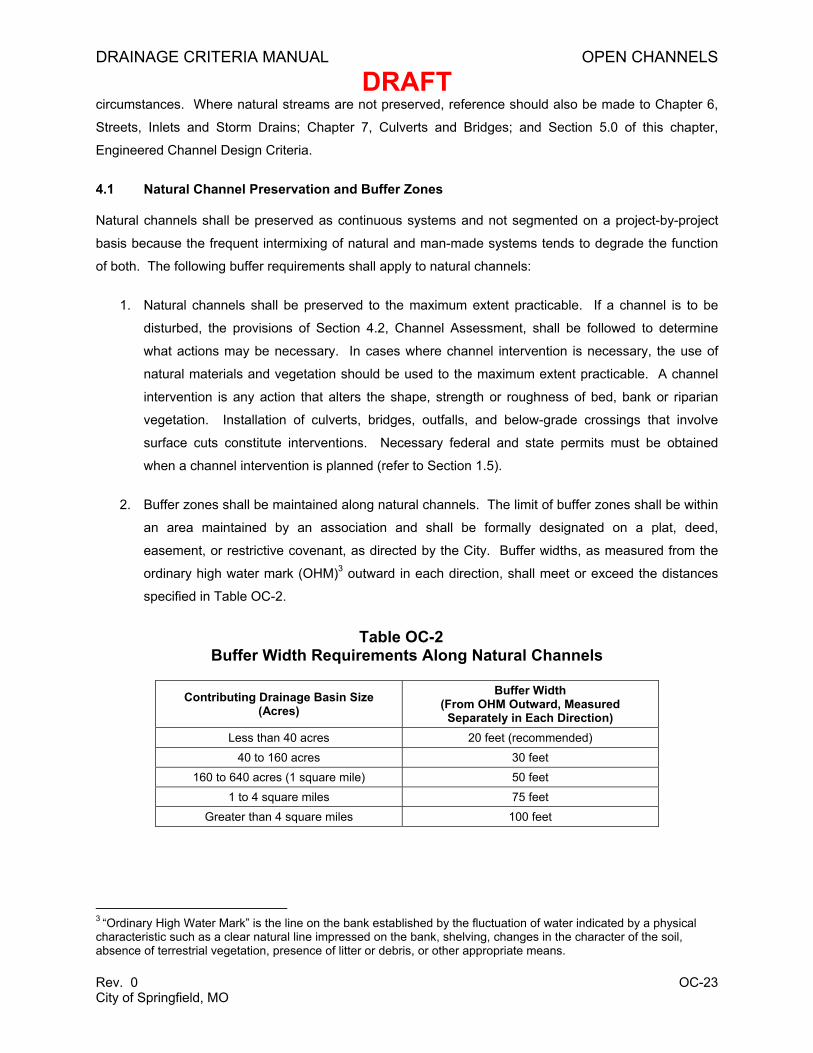
2. Buffer zones shall be maintained along natural channels. The limit of buffer zones shall be within
an area maintained by an association and shall be formally designated on a plat, deed,
easement, or restrictive covenant, as directed by the City. Buffer widths, as measured from the
ordinary high water mark (OHM)3 outward in each direction, shall meet or exceed the distances
specified in Table OC-2.
Table OC-2 Buffer Width Requirements Along Natural Channels
Contributing Drainage Basin Size (Acres)
Buffer Width (From OHM Outward, Measured
Separately in Each Direction) Less than 40 acres 20 feet (recommended)
40 to 160 acres 30 feet 160 to 640 acres (1 square mile) 50 feet
1 to 4 square miles 75 feet Greater than 4 square miles 100 feet
3 “Ordinary High Water Mark” is the line on the bank established by the fluctuation of water indicated by a physical characteristic such as a clear natural line impressed on the bank, shelving, changes in the character of the soil, absence of terrestrial vegetation, presence of litter or debris, or other appropriate means.
DRAINAGE CRITERIA MANUAL OPEN CHANNELS
DRAFT
Rev. 0 OC-24 City of Springfield, MO
3. The City may require additional buffer width for less stable channels or special conditions to
address water quality and ecological needs. The widths specified in Table OC-2 provide only
moderate allowance for widening or migration in channels of average stability. Geotechnical
studies may be required if there is a risk of slope failure due to the condition of underlying soil or
rock materials. If necessary, the buffer width shall be expanded to contain the potential zone of
failure as recommended by a geotechnical engineer. Smaller buffers in isolated locations may be
allowed where provision of the full width is impractical and bank stability concerns have been
addressed. Additional quality buffer areas may be considered as compensation for smaller
buffers through part of the reach.
4. No construction or disturbance of any type, including clearing, grubbing, stripping, fill, excavation,
linear grading, paving, or building is allowed in the buffer zone except by permission of the City.
Dense stands of native vegetation shall be encouraged, particularly in the 25 feet closest to the
top of bank. Exceptions to this policy will be allowed for trails, green space, recreation, and
education purposes, provided that removing vegetation does not pose a threat to the stability or
proper function of the waterway.
5. Unless otherwise accepted by the City, any maintenance of riparian buffers shall be the
responsibility of the property owner. Healthy vegetation in the buffer zone and the capacity to
convey floodwater without excessive backwater effects shall be maintained. Maintenance may
include removal of vines and exotic or diseased vegetation. Trees may not be “topped” but may
be trimmed to prevent damage to overhead utilities. If the property owner fails to maintain the
buffer, the City may, at its discretion, hold the property owner financially responsible for
maintenance conducted by the City.
6. For work on existing facilities already located closer to the channel than allowed, the new
construction shall not encroach closer to the channel. Unstable banks shall be stabilized using
methods described in this chapter. Formal designation of the full buffer zone may not be
required; however, the part of the buffer zone not encroached upon shall be formally designated.
7. The City may approve deviations of the buffer requirement, provided that they are consistent with
the public interest, and where, due to special conditions, a literal enforcement of the provisions
would result in unnecessary hardship. Criteria for variance from the buffer requirement are:
a. Granting of the deviation does not adversely affect the rights of adjacent land owners;
b. Granting of the deviation will not create a public nuisance, induce a public expense, cause
fraud or victimization of the public, or conflict with existing local, federal, or state laws;
DRAINAGE CRITERIA MANUAL OPEN CHANNELS
DRAFT
Rev. 0 OC-25 City of Springfield, MO
c. The spirit of the requirement is observed; and
d. Granting the requested deviation will not adversely affect public safety, convenience, order,
or general welfare.
8. Edge-of-buffer outfalls, located in the outer half of the riparian buffer, shall be designed to
disperse the discharge to promote overland flow, infiltration, and associated water quality
benefits. Overland flow shall be directed to run in the outer portion of the buffer parallel to the
channel direction. This will increase the length of flow and prevent short-circuiting directly into the
stream. Low weirs and berms may be graded to direct flow and encourage short-term ponding.
The buffer zone utilized for infiltration shall be maintained in dense, erosion-resistant grasses or
grasses with TRMs designed to withstand the shear stresses of a 10-year storm. Edge-of-buffer
outfalls shall only be used if each individual outfall can be designed to operate without scour or
the formation of gullies.
The City may also require mitigation for any deviation from the buffer requirement. The mitigation may
include:
a. A significant improvement of riparian corridor quality, as determined by density, forest
structure, species, and diversity;
b. Inclusion of Best Management Practices such as bioswales, micro-detention features, and
vegetated roofs that mimic the thermal, hydrologic, and ecological benefits of the riparian
corridor; and
c. Restoration of physical and ecological stability of the channel system. Measures for local
streambank stabilization such as retaining walls, gabions, and riprap banks do not constitute
restoration and shall not be construed as mitigation.
4.2 Channel Assessment
DRAINAGE CRITERIA MANUAL OPEN CHANNELS
DRAFT
Rev. 0 OC-26 City of Springfield, MO
Prior to any intervention in or utilization of a natural channel, the designer shall conduct a channel
assessment according to the protocol described below. The assessment is intended to protect the
natural channel resources and demonstrate that the responsible engineer has taken measures to assess
and protect the channel. The assessment protocol described here was specifically developed for
designers who may not have training in river mechanics, fluvial geomorphology or related disciplines.
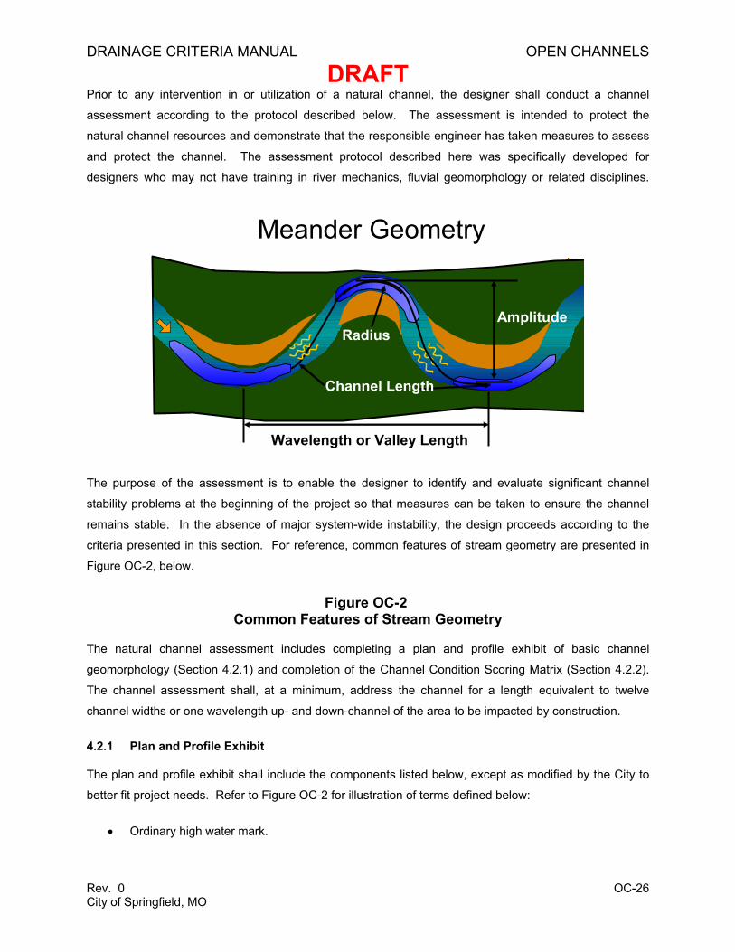
The purpose of the assessment is to enable the designer to identify and evaluate significant channel
stability problems at the beginning of the project so that measures can be taken to ensure the channel
remains stable. In the absence of major system-wide instability, the design proceeds according to the
criteria presented in this section. For reference, common features of stream geometry are presented in
Figure OC-2, below.
Figure OC-2 Common Features of Stream Geometry
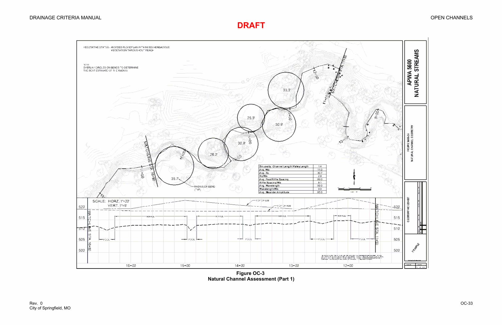
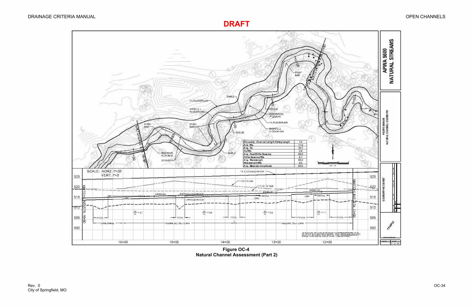
The natural channel assessment includes completing a plan and profile exhibit of basic channel
geomorphology (Section 4.2.1) and completion of the Channel Condition Scoring Matrix (Section 4.2.2).
The channel assessment shall, at a minimum, address the channel for a length equivalent to twelve
channel widths or one wavelength up- and down-channel of the area to be impacted by construction.
4.2.1 Plan and Profile Exhibit
The plan and profile exhibit shall include the components listed below, except as modified by the City to
better fit project needs. Refer to Figure OC-2 for illustration of terms defined below:
• Ordinary high water mark.
Meander Geometry
Wavelength or Valley Length
AmplitudeRadius
Channel Length
DRAINAGE CRITERIA MANUAL OPEN CHANNELS
DRAFT
Rev. 0 OC-27 City of Springfield, MO
• Top of bank.
• Topographic contours (maximum interval of 2 feet).
• "Bank-full" and 1 percent Annual Exceedance Probability (AEP) ultimate-conditions floodplain
(see Items 2 and 3 below).
• Thalweg, locations of riffles and pools, and spacing between riffles (see Item 3 below).
• Exposed bedrock, areas of differing bed and bank soil or rock materials, and the d50 and shear
stress ratio at each riffle (see Item 4 below).
• Springs, sinkholes, gaining, or losing reaches.
• Active scour and depositional areas, point bars, and islands.
• Vegetation within the buffer zone, called out as mowed grass, mowed with trees, unmowed grass
and plants, wooded, and bare. Trees greater than 6 inches in diameter within 25 feet of the top of
bank shall be located individually or by group. The species of dominant trees shall be noted.
• Meander length, wavelength, meander amplitude, bank-full width, and radius of curvature for
each bend.
• Total meander, valley length, and sinuosity for the reach.
• Photographs of main channel, streamside vegetation, and each riffle, appropriately referenced to
plan-view location.
Additional information related to the plan and profile exhibit for the channel assessment is outlined below:
1. Planform Analyses and Inventory: The plan-view of the natural channel using aerial photographs
or planning-level aerial survey shall be plotted at a scale of 1 inch equals 20 feet. A field survey
of the entire reach study area is not required if topographic contours are used with intervals of no
more than 2 feet.
2. Bank-full Width, Depth and Discharge: The geomorphic bank-full (or stream forming) width,
depth, and discharge shall be estimated using field indicators as detailed in Chapter 7 of USDA
(1996). Briefly, field indicators of bank-full depth include internal floodplains or shelves, the lower
limit of woody vegetation, the lowest persistent scour line, and in some cases, the flat tops of
gravel bars. All of the indicators shall be plotted on the profile sheet, and if the best-fit line of the
indicators is parallel to the bed elevation, this elevation is a usable approximation of the bank-full
DRAINAGE CRITERIA MANUAL OPEN CHANNELS
DRAFT
Rev. 0 OC-28 City of Springfield, MO
elevation. Note: disturbed urban channels often do not have a consistent bank-full, or stream
forming, elevation. If field indicators are not used, bank-full flow shall be estimated as the 50
percent AEP flow under predevelopment conditions. The bank-full width and depth are estimated
based on the dimensions of that flow through the existing channel. This assumption is intended
to provide a rough upper estimate of the bank-full flow.
3. Longitudinal Profile and Sections: The elevations of the profile along the thalweg shall be field
surveyed to the nearest 0.1 foot. The following features shall be noted: riffles, pools, exposed
bedrock, sinkholes, springs, and advancing headcuts (areas of bed elevation change that appear
to be actively migrating upstream). The top of left and right bank and any field indicators of bank-
full flow, such as limits of woody vegetation or top of point bars, shall be plotted at the correct
elevation along the profile. The bank-full flow and 1 percent AEP ultimate flow profiles shall be
plotted. One field cross-section shall be surveyed through each pool and riffle, and the depth and
width of bank-full flow and 1 percent AEP ultimate conditions floodplain shall be shown on each
section.
4. Bed and Bank Materials Analyses: The type of rock exposed in the bed and banks shall be
identified. Bank soils shall be reported by Uniform Soil Classification using the visual-manual
procedures (ASTM D 2488-00). The median (d50) particle size shall be determined using visual
observation, grain size analysis of the surface layer, or the Wolman Pebble Count Method
described in Chapter 11 of USDA (1996). A shear stress ratio shall be calculated for each riffle
based on the applied shear at bank-full flow divided by the critical shear of the material in the
riffle, using methods and tables described below. For coarse grain material, the d50 particle size
shall be used.
5. Critical Shear Stress Analysis: The shear stress ratio must be less than 1.0 at the farthest point of
the drawdown curve of any channel intervention, in accordance with the guidelines below:
a. Shear Stress Ratio
The shear stress ratio is defined as:
co ττ / (Equation OC-6)
In which:
τo= average boundary shear stress (lbs/ft2) (see Equation OC-7)
τc = critical shear stress (lbs/ft2) (see Equation OC-8)
If bed and bank materials are distinct, then the shear stress ratio shall be calculated for each.
If the shear stress ratio of either streambed or bank is greater than 1.0, the channel is prone
DRAINAGE CRITERIA MANUAL OPEN CHANNELS
DRAFT
Rev. 0 OC-29 City of Springfield, MO
to near-term adjustment, and any interventions shall be designed to prevent accelerated
erosion. If the bed consists of rock that is prone to fracturing, slaking, or break-up, the
median particle size shall be used for calculation of the ratio.
b. Average Boundary Shear Stress
The average applied shear stress, τo, may be calculated from the hydraulic data as follows:
eo RSγτ = (Equation OC-7)
In which:
τo = average boundary shear stress (lbs/ft2)
γ = specific weight of water (62.4 lb/ft3)
R = hydraulic radius at bank-full or stream forming flow (flow area/wetted perimeter)
Se = slope of energy grade line (averaged over several bends in the area of intervention)
The stream-forming flow may be assumed to be equivalent to the 2-year discharge under
pre-disturbance conditions.
c. Critical Shear Stress
At the critical shear stress, τC, particles in the bed or bank are entrained and scour ensues.
Shield’s method is used for calculating the critical shear stress of spherical, non-cohesive
particles, as follows:
( ) 50dsc γγθτ −= (Equation OC-8)
In which:
τc = critical shear stress (lb/ft2)
θ = Shield’s parameter (0.06 for gravel to cobble, 0.044 for sand) (dimensionless)
γs = specific weight of sediment (160 lb/ft3)
γ = specific weight of water (62.4 lb/ft3)
d50 = median particle size in the surface layer of bed or banks (ft)
DRAINAGE CRITERIA MANUAL OPEN CHANNELS
DRAFT
Rev. 0 OC-30 City of Springfield, MO
There are limited methods for calculating τC for fine-grained material. Field or laboratory testing
generally determines the critical shear stress for these materials. The most widely available
source is Chow (1988). More recently, the USDA Agricultural Research Service National
Sedimentation Laboratory has developed computer software for calculating toe scour (ARS Bank-
Toe Erosion Model, Prototype Version 3.4, 2004). The combination of these two sources is
presented in. Critical shear stress may also be determined from American Society of Civil
Engineers (ASCE) and the Water Environment Federation (WEF) (1992), Figure 9.6, p. 335.
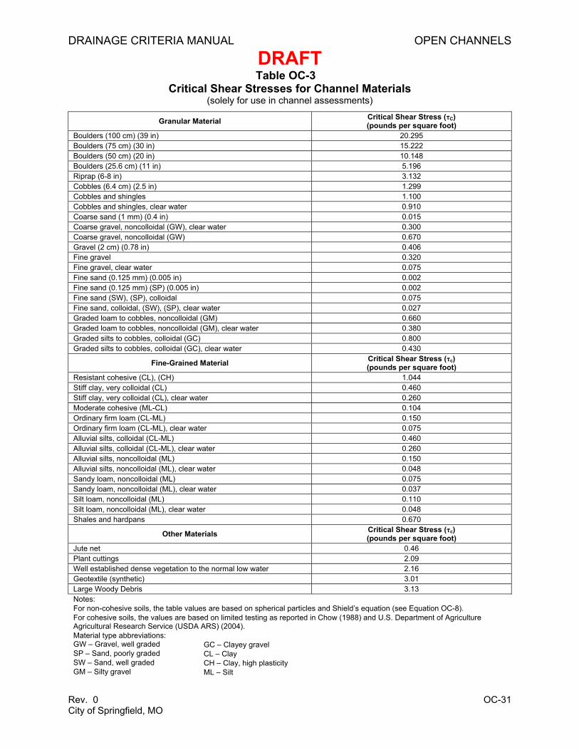
In lieu of calculated values, the τC from Table OC-3 may be used. Table OC-3 presents critical
shear for sediment-laden water and where noted, clear water. The user must exercise judgment
as to future conditions. Clear water values may be used below a heavily piped area, for concrete
channels designed to contain the future flows, or immediately below a managed detention pond.
5. Planform Ratios: Natural channels have generally predictable patterns in plan and profile. A
channel with a planform substantially different than the norm may be exhibiting system-scale
instability. The ratios listed in Table OC-4 shall be calculated, and those outside the typical range
shall be noted. Natural channels are highly variable, and ratios outside these ranges do not
necessarily indicate problems. Planform data must be considered as part of the larger
evaluation.
DRAINAGE CRITERIA MANUAL OPEN CHANNELS
DRAFT
Rev. 0 OC-31 City of Springfield, MO
Table OC-3 Critical Shear Stresses for Channel Materials
(solely for use in channel assessments)
Granular Material Critical Shear Stress (τC) (pounds per square foot)
Boulders (100 cm) (39 in) 20.295 Boulders (75 cm) (30 in) 15.222 Boulders (50 cm) (20 in) 10.148 Boulders (25.6 cm) (11 in) 5.196 Riprap (6-8 in) 3.132 Cobbles (6.4 cm) (2.5 in) 1.299 Cobbles and shingles 1.100 Cobbles and shingles, clear water 0.910 Coarse sand (1 mm) (0.4 in) 0.015 Coarse gravel, noncolloidal (GW), clear water 0.300 Coarse gravel, noncolloidal (GW) 0.670 Gravel (2 cm) (0.78 in) 0.406 Fine gravel 0.320 Fine gravel, clear water 0.075 Fine sand (0.125 mm) (0.005 in) 0.002 Fine sand (0.125 mm) (SP) (0.005 in) 0.002 Fine sand (SW), (SP), colloidal 0.075 Fine sand, colloidal, (SW), (SP), clear water 0.027 Graded loam to cobbles, noncolloidal (GM) 0.660 Graded loam to cobbles, noncolloidal (GM), clear water 0.380 Graded silts to cobbles, colloidal (GC) 0.800 Graded silts to cobbles, colloidal (GC), clear water 0.430
Fine-Grained Material Critical Shear Stress (τc) (pounds per square foot)
Resistant cohesive (CL), (CH) 1.044 Stiff clay, very colloidal (CL) 0.460 Stiff clay, very colloidal (CL), clear water 0.260 Moderate cohesive (ML-CL) 0.104 Ordinary firm loam (CL-ML) 0.150 Ordinary firm loam (CL-ML), clear water 0.075 Alluvial silts, colloidal (CL-ML) 0.460 Alluvial silts, colloidal (CL-ML), clear water 0.260 Alluvial silts, noncolloidal (ML) 0.150 Alluvial silts, noncolloidal (ML), clear water 0.048 Sandy loam, noncolloidal (ML) 0.075 Sandy loam, noncolloidal (ML), clear water 0.037 Silt loam, noncolloidal (ML) 0.110 Silt loam, noncolloidal (ML), clear water 0.048 Shales and hardpans 0.670
Other Materials Critical Shear Stress (τc) (pounds per square foot)
Jute net 0.46 Plant cuttings 2.09 Well established dense vegetation to the normal low water 2.16 Geotextile (synthetic) 3.01 Large Woody Debris 3.13 Notes: For non-cohesive soils, the table values are based on spherical particles and Shield’s equation (see Equation OC-8). For cohesive soils, the values are based on limited testing as reported in Chow (1988) and U.S. Department of Agriculture Agricultural Research Service (USDA ARS) (2004). Material type abbreviations: GW – Gravel, well graded SP – Sand, poorly graded SW – Sand, well graded GM – Silty gravel
GC – Clayey gravel CL – Clay CH – Clay, high plasticity ML – Silt
DRAINAGE CRITERIA MANUAL OPEN CHANNELS
DRAFT
Rev. 0 OC-32 City of Springfield, MO
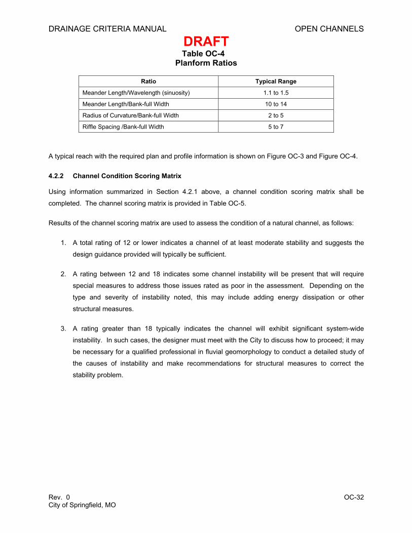
Table OC-4 Planform Ratios
Ratio Typical Range
Meander Length/Wavelength (sinuosity) 1.1 to 1.5
Meander Length/Bank-full Width 10 to 14
Radius of Curvature/Bank-full Width 2 to 5
Riffle Spacing /Bank-full Width 5 to 7
A typical reach with the required plan and profile information is shown on Figure OC-3 and Figure OC-4.
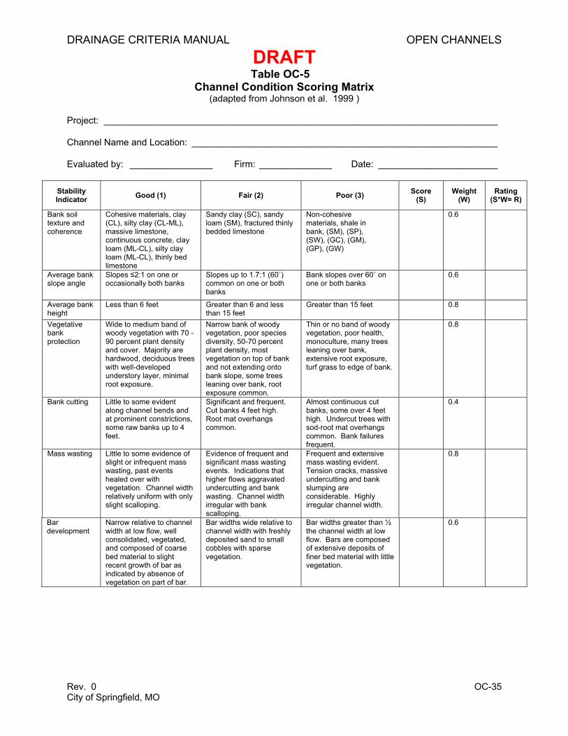
4.2.2 Channel Condition Scoring Matrix
Using information summarized in Section 4.2.1 above, a channel condition scoring matrix shall be
completed. The channel scoring matrix is provided in Table OC-5.
Results of the channel scoring matrix are used to assess the condition of a natural channel, as follows:
1. A total rating of 12 or lower indicates a channel of at least moderate stability and suggests the
design guidance provided will typically be sufficient.
2. A rating between 12 and 18 indicates some channel instability will be present that will require
special measures to address those issues rated as poor in the assessment. Depending on the
type and severity of instability noted, this may include adding energy dissipation or other
structural measures.
3. A rating greater than 18 typically indicates the channel will exhibit significant system-wide
instability. In such cases, the designer must meet with the City to discuss how to proceed; it may
be necessary for a qualified professional in fluvial geomorphology to conduct a detailed study of
the causes of instability and make recommendations for structural measures to correct the
Non-cohesive materials, shale in bank, (SM), (SP), (SW), (GC), (GM), (GP), (GW)
0.6
Average bank slope angle
Slopes ≤2:1 on one or occasionally both banks
Slopes up to 1.7:1 (60˚) common on one or both banks
Bank slopes over 60˚ on one or both banks
0.6
Average bank height
Less than 6 feet Greater than 6 and less than 15 feet
Greater than 15 feet 0.8
Vegetative bank protection
Wide to medium band of woody vegetation with 70 -90 percent plant density and cover. Majority are hardwood, deciduous trees with well-developed understory layer, minimal root exposure.
Narrow bank of woody vegetation, poor species diversity, 50-70 percent plant density, most vegetation on top of bank and not extending onto bank slope, some trees leaning over bank, root exposure common.
Thin or no band of woody vegetation, poor health, monoculture, many trees leaning over bank, extensive root exposure, turf grass to edge of bank.
0.8
Bank cutting Little to some evident along channel bends and at prominent constrictions, some raw banks up to 4 feet.
Significant and frequent. Cut banks 4 feet high. Root mat overhangs common.
Almost continuous cut banks, some over 4 feet high. Undercut trees with sod-root mat overhangs common. Bank failures frequent.
0.4
Mass wasting Little to some evidence of slight or infrequent mass wasting, past events healed over with vegetation. Channel width relatively uniform with only slight scalloping.
Evidence of frequent and significant mass wasting events. Indications that higher flows aggravated undercutting and bank wasting. Channel width irregular with bank scalloping.
Frequent and extensive mass wasting evident. Tension cracks, massive undercutting and bank slumping are considerable. Highly irregular channel width.
0.8
Bar development
Narrow relative to channel width at low flow, well consolidated, vegetated, and composed of coarse bed material to slight recent growth of bar as indicated by absence of vegetation on part of bar.
Bar widths wide relative to channel width with freshly deposited sand to small cobbles with sparse vegetation.
Bar widths greater than ½ the channel width at low flow. Bars are composed of extensive deposits of finer bed material with little vegetation.
0.6
DRAINAGE CRITERIA MANUAL OPEN CHANNELS
DRAFT
Rev. 0 OC-36 City of Springfield, MO
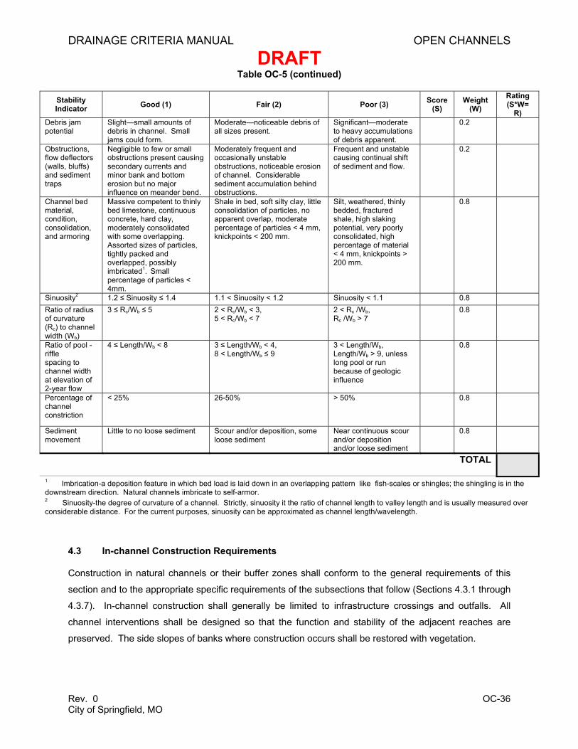
Table OC-5 (continued)
Stability Indicator Good (1) Fair (2) Poor (3) Score
(S) Weight
(W) Rating (S*W=
R) Debris jam potential
Slight—small amounts of debris in channel. Small jams could form.
Moderate—noticeable debris of all sizes present.
Significant—moderate to heavy accumulations of debris apparent.
0.2
Obstructions, flow deflectors (walls, bluffs) and sediment traps
Negligible to few or small obstructions present causing secondary currents and minor bank and bottom erosion but no major influence on meander bend.
Moderately frequent and occasionally unstable obstructions, noticeable erosion of channel. Considerable sediment accumulation behind obstructions.
Frequent and unstable causing continual shift of sediment and flow.
0.2
Channel bed material, condition, consolidation, and armoring
Massive competent to thinly bed limestone, continuous concrete, hard clay, moderately consolidated with some overlapping. Assorted sizes of particles, tightly packed and overlapped, possibly imbricated1. Small percentage of particles < 4mm.
Shale in bed, soft silty clay, little consolidation of particles, no apparent overlap, moderate percentage of particles < 4 mm, knickpoints < 200 mm.
Silt, weathered, thinly bedded, fractured shale, high slaking potential, very poorly consolidated, high percentage of material < 4 mm, knickpoints > 200 mm.
0.8
Sinuosity2 1.2 ≤ Sinuosity ≤ 1.4 1.1 < Sinuosity < 1.2 Sinuosity < 1.1 0.8 Ratio of radius of curvature (Rc) to channel width (Wb)
3 ≤ Rc/Wb ≤ 5 2 < Rc/Wb < 3, 5 < Rc/Wb < 7
2 < Rc /Wb, Rc /Wb > 7
0.8
Ratio of pool -riffle spacing to channel width at elevation of 2-year flow
3 < Length/Wb, Length/Wb > 9, unless long pool or run because of geologic influence
0.8
Percentage of channel constriction
< 25% 26-50% > 50% 0.8
Sediment movement
Little to no loose sediment Scour and/or deposition, some loose sediment
Near continuous scour and/or deposition and/or loose sediment
0.8
TOTAL
1 Imbrication-a deposition feature in which bed load is laid down in an overlapping pattern like fish-scales or shingles; the shingling is in the downstream direction. Natural channels imbricate to self-armor. 2 Sinuosity-the degree of curvature of a channel. Strictly, sinuosity it the ratio of channel length to valley length and is usually measured over considerable distance. For the current purposes, sinuosity can be approximated as channel length/wavelength.
4.3 In-channel Construction Requirements
Construction in natural channels or their buffer zones shall conform to the general requirements of this
section and to the appropriate specific requirements of the subsections that follow (Sections 4.3.1 through
4.3.7). In-channel construction shall generally be limited to infrastructure crossings and outfalls. All
channel interventions shall be designed so that the function and stability of the adjacent reaches are
preserved. The side slopes of banks where construction occurs shall be restored with vegetation.
DRAINAGE CRITERIA MANUAL OPEN CHANNELS
DRAFT
Rev. 0 OC-37 City of Springfield, MO
4.3.1 Energy Management
An important consideration for the design engineer working on a natural channel is to evaluate and
manage the energy throughout the reach of the project. The pre-project and post-project hydraulic and
energy grade lines for the 1-, 10-, and 100-year storms shall be plotted. The region of a channel where
in-stream construction causes a change in these grade lines is considered the zone of influence.
Downstream from the construction region, the extent of the zone of influence shall be generally limited by
energy dissipation and use of naturally occurring or Newbury-style grade control. Grade control
structures shall be designed to dissipate energy sufficiently to match the energy grade line of the project
reach with that of the upstream and downstream adjacent reaches. Design criteria for energy dissipation
and grade control structures are addressed in Section 6.0, Hydraulic Structures and Section 7.0, Small
Grade Control Structures.
There should not be an increase in depth or velocity sufficient to threaten the channel bed or bank.
Within the zone of influence, the energy of the flow on the channel shall be evaluated for the potential of
excessive scour, deposition, initiation of headcuts, or other instability (i.e., consider the shear stress and
energy grade line, and evaluate whether the applied shear is greater than the critical shear along the
channel bed or bank). Upstream from the construction region, the limit of the zone of influence may
extend a distance beyond the construction as a drawdown or backwater curve.
By deliberately designing hydraulic roughness, engineers can dissipate scouring energy and guide it
towards the channel thalweg. Thoughtful use of energy management structures can substantially reduce
the need for channel armor. Spot usage of hard armor is not an acceptable design approach because it
transfers the energy and damage elsewhere in the reach. Instead, the channel shall be designed to
dissipate the energy and alleviate the need for armor.
Boulder drop structures and shaped grade controls are especially useful for focusing flow to the channel
thalweg and away from the banks. When using riprap in in-stream structures, it should be left rough.
Where possible, the riprap should be staked with live vegetation such as shrub willow stakes at the toe of
the slope and up the banks to lock the riprap in place and provide additional stage-dependent energy
dissipation. When installing live stakes into riprap, the stakes must extend at least 12 inches into soil
below the rock and extend roughly 12 inches above it. Since it is difficult to acquire live stakes longer
than 48 inches, and it is also difficult to drive the stakes through more than 24 inches of rock, this is the
practical limit of their use.
Streamside vegetation also provides energy management benefits and should be protected. The
designer shall set the construction limits to not disturb riparian vegetation, except by permission from the
City. Use of vegetation is recommended to increase bank resistance and minimize increases or abrupt
DRAINAGE CRITERIA MANUAL OPEN CHANNELS
DRAFT
Rev. 0 OC-38 City of Springfield, MO
changes in velocities. Vegetative bank or bed stabilization may be required in areas where increases in
depth or velocity are necessary.
4.3.2 Sediment Transport Continuity
To maintain the ability of the channel to transport sediment, the minimum applied shear to the bed of the
channel for the post-project condition shall not be less than 90 percent of the minimum applied shear for
the pre-project condition. This requirement applies to the zone of influence for the 1-, 10-, and 100-year
flows for current and ultimate development conditions. For maximum allowable applied shear, the post-
project condition shall not exceed the critical shear strength of either bed or bank.
4.3.3 Transitions
In-channel structures shall be designed to gradually blend into the natural channel and provide a smooth
transition of both geometry and roughness. Abrupt changes in cross-section, strength of material or
hydraulic roughness tend to concentrate erosive forces and the designer must take particular care to
avoid them. In-channel structures shall be designed to gradually blend into the natural channel and
provide a smooth transition of both geometry and roughness. Robust vegetation such as live stakes is
useful in managing a gradual transition from riprap to native bank material.
4.3.4 Discharge Outfalls
Discharge outfalls into natural open channels from enclosed conduits or constructed channels shall be
designed depending on the type of outfall, as described below. Calculations to evaluate energy
management and sediment continuity, as discussed in Sections 4.3.1 and 4.3.2, are not required for
these outfalls; however, energy dissipation shall be provided at these locations to reduce increased shear
stress caused by development in the watershed. For further discussion on calculations to evaluate
energy management, refer to Chapter 6, Streets, Inlets, and Storm Drains.
4.3.4.1 Primary Outfalls
Primary outfalls are those where the entire main channel upstream is replaced by an enclosed system or
constructed channel that discharges flow in line with the direction of the existing downstream segment.
Energy dissipation shall be provided at the outlet to reduce velocities. Grade control downstream of the
outlet and energy dissipation device shall be provided to prevent undermining of the outfall by future
headcuts. The alignment and location of the outfall and associated energy dissipation and grade control
structures shall make a smooth transition into the downstream channel. Primary outfalls shall be used
whenever the contributing drainage area of the outfalls is greater than 80 percent of the downstream
channel.
DRAINAGE CRITERIA MANUAL OPEN CHANNELS
DRAFT
Rev. 0 OC-39 City of Springfield, MO
4.3.4.2 Tributary Outfalls
Tributary outfalls are those which discharge to a downstream segment that has a drainage area separate
from the tributary that is larger than the drainage area of the tributary itself. Energy dissipation and
transition to natural stream flow shall take place in the tributary, upstream of the confluence with the
larger channel by a distance of at least one channel width. Newbury-style grade control structure(s) in
the tributary upstream of the confluence shall be provided if the tributary flow line is higher than the
adjoining channel or if future incision of the adjoining channel is anticipated. Tributary outfalls may be
used in all situations of tributary flow.
4.3.4.3 Lateral Outfalls
Lateral outfalls are small outfalls that discharge into a natural stream at its embankment. Outfalls shall be
located to enter on a riffle or from the outside of a bend; they should generally not enter from the inside of
a bend. Outfall pipes shall be oriented perpendicular to the flow of the stream, with the invert at or slightly
below the top of the next downstream riffle. Outfalls shall be flush with or setback from the bank. The
bank shall be shaped to provide a smooth transition and protected with reinforced vegetation (preferred)
or riprap.
If the lateral outfall is in a bend, it shall be set back from the existing bank a sufficient distance to account
for future meander migration, and the transition shall be graded and reinforced with vegetation. Riprap or
hard armor protection should not be used in a bend. Perpendicular outfalls may only be used when the
contributing drainage area of the outfall is less than 40 percent of that in the downstream channel.
4.3.4.4 Edge-of-Buffer Outfalls
Edge of buffer outfalls are addressed in the Section 4.1 text regarding natural channel buffer zones.
4.3.5 Culverts, Bridges, and Above-grade Crossings
4.3.5.1 Crossing Location
Crossings should generally be located on a riffle. If the width of the crossing is large relative to the length
of the riffle, then Newbury-style grade control structures shall be provided at the riffles upstream and
downstream to isolate the impact of the crossings.
4.3.5.2 Realignment of Channels
Realignment of channels to accommodate crossings and their approach should be avoided and
minimized as much as possible. Designers proposing to realign a natural channel must thoroughly
document the influence of this action on the upstream and downstream reaches. (Refer to Section 4.2 for
natural channel assessment process). Any areas relocated shall have the banks stabilized with natural
DRAINAGE CRITERIA MANUAL OPEN CHANNELS
DRAFT
Rev. 0 OC-40 City of Springfield, MO
vegetation, and the designer shall reinforce the adjacent upstream and downstream riffles with Newbury-
style grade control structures.
4.3.5.3 Bridges
For bridges, the multi-stage channel shape shall be maintained. Additional cross-sectional channel area
to convey the design flow shall be located above the elevation of the bank-full discharge.
4.3.5.4 Multi-Cell Pipe and Culvert Crossings
Multi-cell pipe and culvert crossings shall be designed to minimize impacts on streams and minimize
maintenance requirements. For crossings that have a cumulative width larger than the bank-full width,
certain guidelines apply to prevent build up of sediment and loss of channel capacity. Those cells wider
than the bank-full width shall have a flow line located at the lowest estimated bank-full depth.
Alternatively, a weir wall or other structure, located upstream of the culvert opening, shall be installed with
sufficient height to prevent access to the cell during flows less than bank-full flow. The weir wall shall be
designed so that the hydraulic efficiency during the 100-year event conditions is not reduced.
4.3.5.5 Culverts
Culverts shall be designed so there is minimal backwater effect at all flows up to the 100-year discharge.
Energy management and sediment transport continuity shall be checked (refer to Sections 4.3.1 and
4.3.2).
4.3.6 Below-grade Stream Crossings
4.3.6.1 Riffle Crossing
Below-grade stream crossings primarily involve utility pipelines. Crossings should generally be located at
riffles or at Newbury-style grade control structures constructed at the riffle. Any necessary encasement of
the utility line may be integrated with, or constructed in addition to, the grade control structure.
4.3.6.2 Pool Crossing
If riffle crossing is not feasible, the crossing should be in a pool that is protected by a downstream
naturally occurring or Newbury-style grade control structure. The top of crossing elevation shall be at
least 2 feet below the top of grade control. Crossings under pools shall not be armored directly, but shall
be protected by downstream grade control at the next downstream riffle.
4.3.6.3 Orientation to Channel
Below-grade crossings shall be perpendicular to the stream whenever possible. If a perpendicular
crossing is not feasible, the Newbury-style grade control structure protecting the crossing shall be
perpendicular.
DRAINAGE CRITERIA MANUAL OPEN CHANNELS
DRAFT
Rev. 0 OC-41 City of Springfield, MO
4.3.6.4 Channel Alteration
Constriction or alteration of the pre-existing channel shape shall be avoided. If alteration occurs,
sediment transport continuity and energy management shall be verified (refer to Sections 4.3.1 and
4.3.2). Streambanks shall be repaired using vegetative methods whenever possible. The hydraulic
roughness of the repaired streambank should match that of the undisturbed streambanks.
4.3.7 Professional Judgment
Natural channels are complex, variable systems whose forms are shaped by local geology and climate.
The standards discussed in this manual are based on generally accepted design principles. However,
these guidelines may not be optimal or sufficient in all cases. Designs shall be completed by qualified
professionals. Although the 100-year floodplain of a natural channel may, in many cases, be larger than
the 100-year floodplain for an engineered channel, it is of the utmost importance to preserve or enhance
the natural corridor because the first Fundamental Canon in ASCE’s Code of Ethics states: “Engineers
shall hold paramount the safety, health, and welfare of the public and shall strive to comply with the
principles of sustainable development in the performance of their professional duties.”
5.0 ENGINEERED CHANNEL DESIGN CRITERIA
This section provides design criteria for engineered open channels. Subjects addressed include: flow
Velocity in simple, uniform channels can be estimated using Manning’s equation. In complex channels
with varied linings, geometry, and curvature, the HEC-2 or HEC-RAS models shall be used to estimate
velocities. When it is necessary to calculate flows under distinctly non-uniform flow, varied or unsteady
conditions, HEC-2 or HEC-RAS are not acceptable, and other appropriate methods must be used.
Open channel design should account for high localized velocities at drops, expansions, contractions, and
other structural controls (see Section 6.0, Hydraulic Structures). The effect of velocity and the selection of
channel lining types are addressed in Section 5.7, Channel Linings.
5.4 Slope
5.4.1 Longitudinal Slope
The criteria for flow regime and flow velocity will generally determine acceptable longitudinal slope.
Minimum slope criteria are specified to provide positive drainage with minimal ponding. Minimum slopes
of channels with natural linings shall be 0.4 percent. For channels with concrete linings, minimum slopes
shall be 0.2 percent.
Maximum slope criteria are defined to keep velocities within acceptable ranges. Maximum slopes are
constrained by the allowable Froude number, Fr. As discussed in Section 3.4, designs that result in Fr
near 1.0 (> 0.8 and < 1.2) shall be avoided by adjusting the design of the cross-section, roughness, and
slope. In general, in cases where drainageways have Fr greater than 0.8, drop structures must be
integrated into the design to control slopes and keep Fr within the acceptable range.
DRAINAGE CRITERIA MANUAL OPEN CHANNELS
DRAFT
Rev. 0 OC-44 City of Springfield, MO
An important consideration when designing channel slope within natural channels or topography is
sinuosity. Straightening of a natural channel inevitably results in an increase in slope. Conversely, for a
constructed channel, a design incorporating meanders can be used to satisfy slope criteria and potentially
reduce the number of grade control structures required.
5.4.2 Side Slopes
Channels with natural linings requiring mowing or regular maintenance shall have a side slope no steeper
than 4H:1V, unless it can be shown that site conditions prohibit construction of a channel with these
dimensions. In such cases, side slopes as steep as 3H:1V may be considered.
For concrete channels, non-vertical side slopes shall not have a slope steeper than 1H:1V, to allow for
safe exit from the channel. An exception is allowed for short transitions between vertical and 1H:1V
concrete channels.
For channels lined with materials other than concrete and when side slopes steeper than 3H:1V are
necessary, slopes armored with riprap, geoweb, or other material may be considered on a case-by-case
basis. The maximum allowable side slope using these types of materials shall be 2H:1V.
Factors to consider when determining side slopes include ease of maintenance, safety, and public
acceptance, particularly in neighborhoods. A fence with a minimum height of 4 feet shall be installed at
the top of any slope steeper than 1H:1V for channels with a depth of 3 feet or more, where homes,
streets, parking lots, buildings or other facilities cause people to be in close proximity.
5.5 Curvature and Superelevation
As discussed in Section 5.4.1, sinuosity may be used to control velocity in conjunction with drops. Every
design is site specific. The use of curvature in a channel design to flatten slope should be done only with
careful consideration given to channel erosion and instability. Layout of small engineered channels
should minimize the number of curves and the degree of curvature of any necessary curves. Curves
shall only be used where it is shown they are necessary due to layout of the development or to create
sinuosity and reduce longitudinal slope. Where curves are used, the centerline of curvature of the
channel shall have a minimum radius of twice the top width of the design flow (25-year event), but not
less than 100 feet.
Supercritical flow in an engineered open channel in an urban area may create hazardous conditions.
Curvature shall not be used in a channel under these conditions. If curvature is proposed, it may be
considered with an analysis of conjugate depths and potential hazards as outlined in Section 5.2, Flow
Regime.
DRAINAGE CRITERIA MANUAL OPEN CHANNELS
DRAFT
Rev. 0 OC-45 City of Springfield, MO
Velocities and depths are higher on the outside of open channel curves. This rise in water surface on the
outside of a curve is referred to as superelevation. Superelevation must be calculated for all curves in
open channels and accounted for in the design of the channel and freeboard. For subcritical flows,
superelevation can be estimated by:
cgrTVy
2
2=∆ (Equation OC-9)
In which:
∆y = difference in water surface elevation between the inner and outer banks of the channel in the bend (resulting from superelevation) (ft)
V = mean flow velocity (ft/s)
T = top width of the channel under design flow conditions (ft)
g = gravitational constant = 32.2 ft/s2
rc = radius of curvature (ft)
Velocity shall be calculated utilizing minimum roughness coefficient values found in Table OC-1 (Section
3.3). When the ratio of the radius of curvature of the channel centerline to the top width of the channel is
less than 8, the velocity of the flow along the outside of the bend shall be calculated using Equation OC-2.
Because of this increase in velocity, it is often necessary to provide increased erosion protection along
the outside of bends. Riprap shall be used when the velocity of the upstream reach for the 25-year storm
is greater than 8 ft/s. (Riprap design information is provided in Section 2.2.4).
Increased erosion protection based on higher bend velocities shall apply to the outside half of the channel
bottom and on the channel side slope for the entire length on the outside of the bend, plus a distance of
two times the top width downstream of the bend. In cases where an outside bend in a grass-lined
channel needs protection, riprap shall be covered, if possible, with soil and vegetation to provide a
grassed-lined channel appearance. Buried riprap may lose vegetated cover in a major flood and require
re-burial and revegetation.
5.6 Freeboard
The required freeboard for engineered open channels is dependent on the type of channel:
• For concrete channels, the required freeboard is 6 inches above the 25-year water surface.
• For other types of channel linings, the required freeboard is 1 foot above the water surface,
except for channels where the 25-year flow depth is 12 inches or less; in such cases the channel
shall have a freeboard of 6 inches above the 25-year water surface.
DRAINAGE CRITERIA MANUAL OPEN CHANNELS
DRAFT
Rev. 0 OC-46 City of Springfield, MO
For all channel types, the 100-year water surface, including the freeboard, shall remain within the
drainage easement.
It must be shown that the lowest enclosed space of all buildings is at least 1 foot above the 100-year
water surface elevation at the upstream side of the building. Particular care in setting floor elevations
shall be taken along channels existing within backwater conditions of existing or proposed culverts. In
these cases, the water surface must be determined using the appropriate hydraulic analysis found in
Chapter 7, Bridges and Culverts.
In cases where curves exist, freeboard must be above the water surface calculated by adding the
superelevation, from Equation OC-7, to the normal water surface elevation.
5.7 Linings
Typical lining options for engineered open channels are listed and summarized in Section 2.2. As
discussed previously, channel linings using natural materials are preferred. Proper planning to provide
enough space and to install structural controls is necessary to enable the use of open, vegetated
drainage systems to the maximum extent practicable.
Allowable velocities associated with various types of channel linings are summarized in Table OC-6
(Section 5.3). Velocities can be controlled using a variety of design options, including grade control
structures, wide or flat channel cross-sections, and increased channel roughness.
Design criteria for different types of engineered channel linings are provided in Sections 5.7.1 through
5.7.6.
5.7.1 Soil Bioengineered Lining
Soil bioengineering integrates native vegetation as a structural element of streambank stabilization.
Whether used alone or in combination with inert natural or manmade materials, plants provide
mechanical, hydrologic, and hydraulic benefits. Advantages of soil bioengineering may include:
• Effective protection of streambanks from scouring and overland flows
• Effective energy dissipation in the stream channel
• Protection of aquatic habitat and provision of mosquito control benefits through stream shading
and supply of organic materials
• High terrestrial habitat values
• Substantial capacity for self-repair and simple predictable maintenance
DRAINAGE CRITERIA MANUAL OPEN CHANNELS
DRAFT
Rev. 0 OC-47 City of Springfield, MO
• High aesthetic values
Despite the significant reinforcement provided by soil bioengineering, these treatments should only be
used in relatively stable channels or subsequent to systemic stabilization. Soil bioengineering is
particularly useful for repairing disturbed banks after construction access or repairing local scour or
erosion. Before attempting to reinforce a streambank using soil bioengineering, the designer shall
determine whether the instability is caused by fluvial erosion processes or is the result of underlying
geotechnical instability. If there is a weaker plane below the root zone, soil bioengineering will not reduce
the risk of slope failure. Soil bioengineering alone is not appropriate in areas where rapid drawdown can
occur, such as in a spillway or dam embankment. In accordance with the principles of NRCS (1996) and
Gray and Sotir (1996), bioengineering projects shall:
• Be self-sustaining or reduce requirements for future human support
• Use native, living materials for restoration
• Restore the physical, biological, and chemical functions and values of streams or shorelines
• Improve water quality through reduction of temperature and chronic sedimentation problems
• Provide opportunities to connect fragmented riparian areas
• Retain or enhance the stream corridor or shoreline system
Guidelines for plants used in soil bioengineering in open channels include:
• Selection of plants and specifications for planting methods and soil amendments shall be
prepared by a professional competent in the biological and stabilization properties of plants.
• Plants selected shall be appropriate to local conditions and be native varieties to the greatest
extent practical. Evaluation of local conditions includes assessment of site microclimate, bank
slope, soil composition, soil strength and fertility, type and condition of existing vegetation,
proximity to existing infrastructure, soil moisture conditions, and likelihood of wildlife predation.
Engineering factors influencing plant selection include frequency, height, and duration of channel
inundation, near-bank shear stress, size and volume of bed load, as well as depth and frequency
of scour.
• Plants may be either locally harvested or purchased from commercial nurseries. When
harvesting, no more than 10 percent of a given stand may be removed, and no plant on the state
rare or endangered species list may be harvested or damaged in harvesting operations. Plant
DRAINAGE CRITERIA MANUAL OPEN CHANNELS
DRAFT
Rev. 0 OC-48 City of Springfield, MO
material grown near the metropolitan area is adapted to local climatic conditions and is preferred
over more remote sources. Some species such as red maple are particularly sensitive to locale
and may only be used if locally available. Seed, plant plugs, rhizomes, whips, live stakes, bare
root, and container stock may be used. Turf grasses, noxious, or invasive species shall not be
used. A wide variety of plant species shall be used to provide greater reliability to a design. For
critical functions such as protection from toe scour, a minimum of three species should generally
be employed.
5.7.2 Grass Lining
When it is not feasible to preserve a natural drainageway or construct a naturalized channel, the preferred
method of conveyance is a grass-lined open channel. The design velocity in the channel will determine
the type of grass lining to use (see Table OC-6 [Section 5.3] for allowable velocities for different types of
grass linings). Design velocity should be controlled using grade control structures (see Section 6.0,
Hydraulic Structures). Channels with relatively low design velocities may be seeded and mulched. If
design velocities exceed the allowable for seed and mulch, the channel shall be sod, approved TRM, or
approved reinforced sod installed up to the level of the 25-year water surface. Detailed installation
specifications that meet or exceed the manufacturer’s requirements must be provided to the City for
approval. Maintenance specifications must also be provided for approval to ensure grass growth and
repair and replacement of any failed TRM or sod for a warranty period of one year.
A typical detail of an improved natural channel or composite channel is shown in Figure OC-5.
Figure OC-5 Typical Cross-section of an Improved Natural Channel or Composite Channel
Under bridges, vegetation can be difficult to grow and/or maintain. Therefore, beneath bridges, an
erosion-resistant hard lining shall be used, with special care given to erosion protection at each end
where the hard lining transitions to the vegetated channel.
DRAINAGE CRITERIA MANUAL OPEN CHANNELS
DRAFT
Rev. 0 OC-49 City of Springfield, MO
Calculations for sizing a grass-lined channel using hydraulic equations from Section 3.0, Open Channel
Design Principles and criteria from Section 5.0, Engineered Channel Design Criteria can be performed
using the Design of Trapezoidal Grass-lined Channel Worksheet of the SF-Channels Spreadsheet. For
the design of a grass-lined channel with a low-flow channel, the Design of Composite Channel Worksheet
of the SF-Channels Spreadsheet can be used. An example of this tool is provided in Example OC-2 at
the end of this chapter.
5.7.3 Manufactured Hard Lining
Higher flow velocities may require a manufactured hard lining, such as articulated blocks, cabled concrete
blocks or other materials. Manufactured hard linings that allow for plant growth and infiltration are
preferred to impervious concrete channels. Allowable design velocities for manufactured hard linings are
specified in Table OC-6 (Section 5.3). In cases where a manufactured hard lining is required, the channel
must be lined with an approved material up to the level of the 25-year water surface. Detailed installation
specifications that meet or exceed the manufacturer’s requirements must be provided to the City for
approval. Maintenance specifications must be provided for approval to ensure plant growth, repair and
replacement of any failed blocks, mats or other materials for a warranty period of one year.
5.7.4 Riprap Lining
Riprap lining should be used only when design constraints prevent the channel design velocity from
falling within the allowable range for vegetated channels. Rock used for riprap shall be hard, durable,
angular in shape, and free from cracks, overburden, shale, and organic matter. Neither breadth nor
thickness of a single stone should be less than one-third its length, and rounded stone should be avoided.
Criteria for rock sizing, thickness of riprap layer, and thickness of riprap bedding material are provided in
the following subsections.
5.7.4.1 Rock Sizing
Equation OC-8 relates flow velocity, channel longitudinal slope, mean rock diameter, and the specific
gravity of the stone being used for riprap.
5.4)1( 66.05.0
50
17.0=
−sGd
VS (Equation OC-8)
In which:
d50 = mean rock diameter (feet)
V = mean channel velocity (ft/s)
S = longitudinal channel slope (ft/ft)
DRAINAGE CRITERIA MANUAL OPEN CHANNELS
DRAFT
Rev. 0 OC-50 City of Springfield, MO
Gs = specific gravity of stone (minimum = 2.6 for Springfield area)
Equation OC-9, derived from Equation OC-8, has the variable for mean rock diameter removed. Solving
Equation OC-9 provides a value, K, which is referenced in Table OC-7 to determine the specific size of
riprap to use for lining an open channel.
66.0)1(
17.0
−=
sG
VSK (Equation OC-9)
Equation OC-8 and Equation OC-9 (and hence Table OC-7) are applicable only for cases where:
• Fr < 0.8
• Channel side slope is no steeper than 2H:1V
Equation OC-8, Equation OC-9, and Table OC-7 are not intended for use in sizing riprap for rundowns or
culvert outlet protection. Information on rundowns and protection of culvert outlets is provided in Section
6.0, Hydraulic Structures.
To size riprap for an open channel, solve Equation OC-9 for K to identify the appropriate type of riprap
from Table OC-7. A check must be conducted to confirm that Fr is less than 0.8 (see Equation OC-5 in
Section 3.4 to calculate Fr). This check is performed automatically when using the Design of Riprap
Channel Worksheet in the SF-Channels Spreadsheet. Riprap types specified in Table OC-7 are based
on a specific gravity of 2.6. Classification and gradation of ordinary riprap types are outlined in Table OC-
8. Riprap types VL, L, and M, which are relatively small and light, should be buried with on-site topsoil
and vegetated. For boulders, classification and size criteria are provided in Table OC-9.
Table OC-7 Riprap Requirements for Channel Linings
K Value
66.0
17.0
)1( −=
sGVSK
Rock Type
< 3.3 VL**(d50 = 6 inches)
> 3.3 to < 4.0 L**(d50 = 9 inches)
> 4.0 to 4.6 M**(d50 = 12 inches)
> 4.6 to 5.6 H**(d50 = 18 inches)
> 5.6 to 6.4 VH**(d50 = 24 inches) *Applicable only where Fr < 0.8 and side slopes are no steeper than 2H:1V. ** Use Gs = 2.6 unless the source of rock and its density are known at the time of design.
DRAINAGE CRITERIA MANUAL OPEN CHANNELS
DRAFT
Rev. 0 OC-51 City of Springfield, MO
Table OC-8 Classification and Gradation of Ordinary Riprap
Riprap Designation Percent (%) Smaller Than Given by Weight
Intermediate Rock Dimension (inches) d50 (inches)*
Type VL 70-100 50-70 35-50 2 -10
12 9 6 2
6**
Type L 70-100 50-70 35-50 2-10
15 12 9 3
9**
Type M 70-100 50-70 35-50 2-10
21 18 12 4
12**
Type H 70-100 50-70 35-50 2-10
30 24 18 6
18
Type VH 70-100 50-70 35-50 2-10
42 33 24 9
24
* d50 = mean particle size (intermediate dimension) **Mix VL, L, and M riprap with 30 percent (by volume) topsoil and bury it with 6 or more inches of topsoil, all vibration compacted.
Table OC-9 Classification of Boulders
Boulder Classification Nominal Size and [Range in
Smallest Dimension of Individual Rock Boulders (inches)]
Maximum Ratio of Largest to Smallest Rock Dimension of
VH (d50 = 24 in) 4 6 8 1 May substitute one 12-inch layer of Type II bedding. The substitution of one layer of Type II bedding shall not be permitted at drop structures. Use of a combination of filter fabric and Type II bedding at drop structures is acceptable. 2 Fifty percent or more retained on the #40 sieve.
A second method for establishing gradation requirements for granular bedding utilizes a procedure
referred to as the Terzaghi-Vicksburg (T-V) design (Posey 1960, USACE 1970). The T-V filter criteria
DRAINAGE CRITERIA MANUAL OPEN CHANNELS
DRAFT
Rev. 0 OC-53 City of Springfield, MO
establish an optimum bedding gradation for a specific channel soil. Specifications for the T-V filter relate
the gradation of the protective upper layer (filter) to that of the lower bed material (base) by the following
Application of channel side slope bedding is shown in Figure OC-6.
Figure OC-6 Riprap Channel Side Lining with Toe Protection
5.7.4.3.2 Filter Fabric
Filter fabric may be used in some cases as an alternate to bedding material. Filter fabric may be used if
the riprap d50 is less than 12 inches, longitudinal slope is less than 2 percent, and side slopes are no
steeper than 3H:1V.
Filter fabric provides filtering action only perpendicular to the fabric and is not a substitute for granular
bedding. Filter fabric has a relatively smooth surface, which provides less resistance to stone movement.
The maximum side-slope criterion of 3H:1V is to reduce the potential for stone movement. Since tears in
DRAINAGE CRITERIA MANUAL OPEN CHANNELS
DRAFT
Rev. 0 OC-54 City of Springfield, MO
filter fabric greatly reduce its effectiveness, placing riprap directly on the fabric is not allowed, and care
must be exercised during construction.
At drop structures and sloped channel drops, where seepage forces may run parallel to the fabric and
cause piping along the bottom surface of the fabric, special care is required. Seepage parallel with the
fabric must be reduced by folding the edge of the fabric vertically downward approximately 2 feet (similar
to a cutoff wall) at 12-foot intervals along the installation, particularly at the entrance and exit of the
channel reach. Filter fabric must be installed from downstream to upstream, with upstream fabric placed
on top of downstream fabric and lapped a minimum of 12 inches at roll edges.
Filter fabric has only a single equivalent pore opening between the channel bed and the riprap. Fine silt
and clay can clog the openings and prevent free drainage, increasing failure potential due to uplift. For
this reason, a double granular filter is often more appropriate bedding for fine silt and clay channel beds.
Calculations for sizing a riprap-lined channel using hydraulic equations from Section 3.0, Open Channel
Design Principles and criteria from Section 5.0, Engineered Channel Design Criteria are shown in
Example OC-3 using the Design of Riprap Channel Worksheet of the SF-Channels Spreadsheet.
Example OC-3 is located at the end of this chapter.
5.7.5 Grouted Boulders
Grouted boulders provide a useful lining option for low-flow channels and steep banks; however, boulders
larger than 18 inches may be difficult to obtain in the Springfield area. Grouted boulders shall be placed
directly on subgrade. Full penetration of grout around the lower two-thirds of the rock is essential for
successful grouted boulder performance. Grout shall be injected in a manner that minimizes air voids
between the grout, subgrade, and boulders. Grout shall be injected with a grout pump and placed by
lowering the grouting nozzle to the bottom of the boulder layer and building up the grout from the bottom
up, while using a vibrator or aggressive manual rodding. Inject the grout to a depth equal to two-thirds of
the boulders’ heights, while keeping the upper one-third ungrouted and clean. Remove all grout splatters
off the exposed boulder portion immediately after grout injection using wet brooms and brushes.
Technical specifications for grout mix and grout placement are provided with Figure OC-9 in Section
7.1.4.3.
5.7.6 Concrete Lining
Concrete lining shall be used only when design constraints prevent the channel design velocity from
falling within the allowable range for vegetated channels. Generally, concrete channels should only be
used for retrofitting in existing urban areas where space is constrained. Well-planned, new developments
should not require the use of concrete-lined channels.
DRAINAGE CRITERIA MANUAL OPEN CHANNELS
DRAFT
Rev. 0 OC-55 City of Springfield, MO
All concrete lining shall be designed to withstand the anticipated hydrodynamic and hydrostatic forces.
Trapezoidal channels shall have side slopes no steeper than 1H:1V. Concrete floors and sidewalls for
trapezoidal channels shall have a minimum thickness of 6 inches and be reinforced with woven wire or
fiber mesh concrete. Rectangular channels shall be structurally designed for all foreseeable loads. All
walls shall have a minimum thickness of 6 inches with designed steel reinforcement. In addition, a fence
or handrail is required along the top of all channel walls if the channel depth is 3 feet or more, and it is
anticipated people will be in close proximity.
Concrete joints shall meet the following criteria:
• Channels shall be constructed of continuously reinforced concrete without transverse joints
• Expansion/contraction joints shall be installed where new concrete lining is connected to a rigid
structure or to an existing concrete lining that is not continuously reinforced.
• Longitudinal joints, where required, shall be constructed on the sidewalls at least 1 foot vertically
above the channel invert.
• All joints shall be designed to prevent differential movement.
• Construction joints are required for all cold joints and where the lining thickness changes.
Reinforcement shall be continuous through the joint.
Calculations for sizing of a concrete-lined channel using hydraulic equations from Section 3.0 and criteria
from this section are shown in Example OC-4 using the Normal and Critical Flow Analysis Worksheet in
the SF-Channels Spreadsheet.
5.8 Cross-section
In addition properly designing channel linings, as described in Sections 5.7.1 through 5.7.6, the channel
cross-section must be designed to achieve the desired velocities, as well as other objectives such as
satisfying needs for wildlife habitat and open space. The most desirable cross-section is one that is
relatively wide and primarily vegetated to provide benefits related to recreation, maintenance, safety,
water quality, downstream impacts, and habitat.
The channel bottom width shall be designed to satisfy the hydraulic capacity of the cross-section,
recognizing the allowable range of velocity, depth, and Froude number. For a given discharge, the
bottom width can be calculated using the depth, velocity, and Froude number constraints given in this
chapter.
DRAINAGE CRITERIA MANUAL OPEN CHANNELS
DRAFT
Rev. 0 OC-56 City of Springfield, MO
For grass-lined channels, as discussed in Section 5.4.2, the channel shall have a maximum side slope of
4H:1V for safety and aesthetics. A minimum side slope of 1 percent shall be provided for positive
drainage. When base flow is present or is anticipated as the drainage area develops, a trickle or low-flow
channel shall be provided. See Section 5.9 for low-flow channel design.
For riprap-lined channels, as discussed in Section 5.5.2, the channel and other armored materials should
have a preferred side slope of 3H:1V with a maximum side slope of 2H:1V. Where only the channel sides
are to be lined, the riprap blanket shall extend at least 3 feet below the channel flow line, and the
thickness of the blanket below the existing channel bed shall be increased to at least 3 times d50 to
accommodate possible channel erosion.
Concrete-lined channels that are not rectangular shall have a maximum side slope of 1H:1V.
5.9 Low-flow Channels
Low-flow channels are necessary depending on the type of channel lining and the conditions that exist. A
low-flow channel is necessary under these conditions:
• Vegetated channels where:
o Baseflow exists
o High peak runoff from developed areas may cause erosion of vegetated areas
o 2-year flow exceeds 5 cfs (for unreinforced grass only).
• All types of channel linings in locations where erosion could potentially occur, such as
downstream of point discharges.
If conditions warrant a low-flow channel, the low-flow channel shall be designed to convey the 1-year flow
under fully developed watershed conditions. Variations from this design must be justified by the
hydrologic characteristics of the site.
Low-flow channel requirements vary by channel type, as listed below:
• In naturalized channels, low-flow channels typically are unlined. Depending on the projected
stresses, riffle areas may require some reinforcement.
• In engineered grass-lined channels, riprap, boulders, or a soil-riprap mix for the low-flow channel
lining can provide a stable, vegetated low-flow channel. Soil and riprap should be mixed prior to
placement for these low-flow channels. Vegetated portions of the channel can remain dry and
DRAINAGE CRITERIA MANUAL OPEN CHANNELS
DRAFT
Rev. 0 OC-57 City of Springfield, MO
easy to mow and maintain. Typical details of a grass-lined channel with a low-flow channel are
shown in Figure OC-5.
• In engineered channels that are not grass-lined, low-flow channels typically consist of riprap or
boulders. If concrete low-flow channels are considered, a specific approach for addressing
disease vectors associated with standing water, such as mosquitoes, should be identified.
5.10 Outfalls
Outfalls into channels must be designed with consideration given to the nature and condition of the
receiving channel. Such outfalls shall be perpendicular to flow or directed downstream. Any protrusions
of pipes or other structures into the channel must be trimmed flush with the main channel wall or bank.
Discharges into natural, vegetated or reinforced vegetated channels shall be at the flow line, in a manner
consistent with the channel outfalls for natural channels described in Section 4.3.4. Vegetated or
reinforced vegetated channels are generally not capable of withstanding point discharges. Energy
dissipation, such as a headwall or riprap protection, shall be designed around the outfall to minimize
bank, channel or wall erosion. Energy dissipation in the main channel shall be designed to withstand the
flows that occur there.
Discharges into channels lined with concrete or riprap generally require no special protection against
erosion. Discharges into hard-lined channels shall be a minimum of 1 foot above the flow line.
6.0 HYDRAULIC STRUCTURES
This manual does not provide detailed information related to the design of large hydraulic structures. In
most cases where large or complex hydraulic structures are proposed, a preliminary meeting shall be
held with City staff. If it is determined that the structure is necessary, a qualified professional in the
design of hydraulic structures must be retained for the design.
Specific types of hydraulic structures and suggested references for the designer are listed in Table OC-11
While Table OC-11 is not intended to provide a complete list of hydraulic structure types or reference
information, it does provide a good general summary of suggested resources for a design engineer
working on hydraulic structures. Full citations are provided in Section 9.0, References. For smaller, less
complex drop structures, design information is provided in Section 7.0.
DRAINAGE CRITERIA MANUAL OPEN CHANNELS
DRAFT
Rev. 0 OC-58 City of Springfield, MO
Table OC-11 Suggested Further References for Hydraulic Structures
Type of Hydraulic Structure Suggested Reference Information
General hydraulic analysis Chow (1959), Rouse (1949), USACE (1994), Henderson (1966), Barnes (1967), Bathurst, Li, and Simons (1979), Sabol (1982), Aisenbrey et al. (1978)
Hydraulic jump Chow (1959), Little and Daniel (1981), Little and Murphey (1982), USACE (1994), Peterka (1984), Sandover et al. (1962)
Channel Grade Control
Seepage analysis Cedergren (1967), USBR (1987), Taylor (1967)
Conduit Outlet Aisenbrey et al. (1974), Biechley (1971), Peterka (1984)
Transitions and Constrictions Chow (1959), Rouse (1949), FHWA (2000)
Bends and Confluences Chow (1959), Rouse (1949)
Rundowns Chow (1959)
Energy Dissipators Corry et al. (1975), Peterka (1984), Rhone (1977)
Riprap (Different Applications) Riprap (multiple applications) Abt et al. (1977), Anderson (1968), Anderson et al. (1973), Hughes (1976), Li Simons Assoc. (1989), Maynord (1978), Maynord and Ruff (1987), Reese (1986), USACE (1994), Reese (1984), Stevens et al. (1976), Stevens (1981), U.S. Bureau of Public Roads (1967), US SCS (1976), Wittler and Abt (1988), NCHRP (2006)
7.0 SMALL GRADE CONTROL STRUCTURES
This section provides design criteria for relatively small grade control structures. Structures of this type
are typically used to maintain acceptable velocities and flow characteristics in order to protect channel
stability.
7.1 Small Grade Control Structures
Designs for small grade control structures are presented in this section for a maximum drop height of 2
feet for stable, non-boatable grass channels that meet the design conditions listed in Table OC-12.
DRAINAGE CRITERIA MANUAL OPEN CHANNELS
DRAFT
Rev. 0 OC-59 City of Springfield, MO
Table OC-12 Design Criteria for Small Grade Control Structures
Design Parameter Criteria
Peak flow rate 200 cfs
Typical channel longitudinal slope 0.3 to 0.8 percent
Normal flow depth (maximum) 3 feet
Flow velocity (maximum) 6 ft/s
Froude number (maximum) 0.8
Geotechnical condition (assumed) Moderate strength clay with chert
Design criteria presented in this section are for grade control structures in relatively small channels and
are based on the assumptions that effects are minimal from channel curvature, unstable beds, other
hydraulic structures, or other special conditions that require detailed analysis. It is the responsibility of the
design professional to determine if these assumptions are met. In addition, grade control structure
dimensions may require modifications to adjust the design to field conditions. Deviations from maximum
height and flow criteria, or altering designs to have dimensions less than the minimum specified, require
project-specific design and analysis. In all cases, the design professional is responsible for the structural
integrity of the grade control structure.
The following five types of small grade control structures are described in this section:
The process for selecting the most suitable type of small grade control structure for a specific application
is described in Section 7.1.1.
DRAINAGE CRITERIA MANUAL OPEN CHANNELS
DRAFT
Rev. 0 OC-60 City of Springfield, MO
7.1.1 Small Grade Control Structure Selection Process
7.1.1.1 Initial Evaluation Steps
Prior to selecting the most suitable type of grade control structure for the project, these initial evaluation
steps must be completed:
1. Define the representative channel design flows for the 25-year storm event. If the 25-year design
storm flow rate is greater than 200 cfs, the small grade control structure design process described
in this section is not appropriate. In such cases, designs for larger grade control structures (see
Section 6.0, Hydraulic Structures) shall be developed. If the 25-year design storm flow rate is
less than 200 cfs, then the 25-year design flow rate should be used as the basis for peak flow for
the small grade control structure design. The channel dimensions and longitudinal slope
necessary to convey the 25-year design flow can then be approximated.
2. Determine whether the channel has perennial or intermittent flow. If the channel has intermittent
flow, then the Newbury-style structure is not suitable, and an alternative type of grade control
structure should be selected.
3. Evaluate preliminary grading requirements for the channel and grade control structures, taking
into consideration the 2-foot limit on grade control structure heights when using the design criteria
outlined in this section.
After completing the initial evaluation steps, the designer should refer to the evaluation criteria described
in Section 7.1.1.2 to select the most suitable type of grade control structure for the site application.
7.1.1.2 Grade Control Structure Evaluation Criteria
Several factors should be taken into consideration to select the appropriate type of small grade control
structure for a specific location. Primary considerations include:
• Public safety—Can the grade control structure convey the 25-year design flow without causing
undue safety hazards (e.g., creation of reverse roller hydraulic condition that can potentially
entrap a person)?
• Functional hydraulic performance of the structure—Can the grade control structure convey the
design flow without damaging the structure or the downstream channel?
Secondary considerations include:
• Land use—Is the grade control structure compatible with its surroundings?
DRAINAGE CRITERIA MANUAL OPEN CHANNELS
DRAFT
Rev. 0 OC-61 City of Springfield, MO
• Cost—Does the grade control structure represent the most economical option for channel grade
control while simultaneously achieving other design objectives?
• Ecological impact—Is the amount of disturbed area caused by the grade control structure
acceptable with respect to the habitat where the structure will be located? Will the completed
structure provide habitat benefits and allow aquatic species to move longitudinally upstream and
downstream through the structure?
• Aesthetics—Is the grade control structure aesthetically pleasing with respect to its surroundings?
(Aesthetics are subjective and are best evaluated by a landscape architect with experience in
drainage design.)
• Maintenance—Does the grade control structure have excessive maintenance requirements or
costs, relative to other grade control structures?
• Environmental permitting—Are there wetlands, habitat disturbance, or other concerns that require
permitting for the grade control structure? (Soliciting expertise in environmental permitting is
suggested in cases where such matters are a concern).
Using the primary and secondary considerations listed above, the five types of small grade control
structures described in Section 7.1 were evaluated. A summary of the evaluation is presented in Table
OC-13 and a summary of the relative advantages and disadvantages of each structure type, based on the
evaluation criteria, is provided in Table OC-14. Based on the information presented in Table OC-13 and
Table OC-14, the designer can select the type of small grade control structure that is most suitable for the
unique conditions at a specific project site.
DRAINAGE CRITERIA MANUAL OPEN CHANNELS
DRAFT
Rev. 0 OC-62 City of Springfield, MO
Table OC-13 Summary of Considerations for Selecting Small Grade Control Structure Type
Grade Control Structure Type Considerations for Grade Control
Structure Design Grouted
Sloping Boulder Concrete Sloping
Vertical Hard Basin Newbury-style Sculpted
Concrete Primary Considerations Public Safety More preferred for areas
with high public usage Less preferred for areas with high public usage
Less preferred for areas with high public usage, (though the potential for reverse rollers and backflow eddies is reduced with drop of 2 feet or less)
More preferred for areas with high public usage
More preferred for areas with high public usage
Functional Hydraulic Performance
Good flexibility of layout options. Roughness effective for dissipating kinetic energy
Maximum vertical drop limited by public safety concern
Maximum vertical drop limited by public safety concern (see above)
Good flexibility of layout options. Roughness effective for dissipating kinetic energy
Good flexibility of layout options
Secondary Considerations Land Use (Contextual Design)
Provides natural channel appearance
Best suited for urban setting
Best suited for urban setting
Provides natural channel appearance
Provides natural channel appearance
Cost Costs comparable for all options
Costs comparable for all options
Costs comparable for all options
Costs comparable for all options
Costs comparable for all options
Ecological Impacts Creates larger footprint than vertical drop
Creates larger footprint than vertical drop. Has no habitat or water quality benefits and may be detrimental.
Creates smallest footprint of any option. Has no habitat or water quality benefits and may be detrimental.
Provides refuge for macroinvertebrates and small fish, fish passage, simulates naturally occurring riffle. Provides refuge during flow event.
Creates larger footprint than vertical drop. Has no habitat or water quality benefits and may be detrimental.
Aesthetics Natural-appearing, aesthetic option
Less aesthetic relative to other options
Less aesthetic relative to other options
Natural-appearing, aesthetic option
Natural-appearing, aesthetic option
Maintenance Potential for scour erosion at downstream end
Potential for scour erosion at downstream end
Sediment deposition in impact basin, scour erosion at downstream end of basin
Little potential for scour erosion at downstream end
Potential for scour erosion at downstream end
Environmental Permitting More disturbed area than other options
More disturbed area than other options
Less disturbed area than other options
More disturbed area than other options. Simulates naturally occurring riffle. No concrete in stream. When vegetated, supports both terrestrial and aquatic species.
More disturbed area than other options
DRAINAGE CRITERIA MANUAL OPEN CHANNELS
DRAFT
Rev. 0 OC-63 City of Springfield, MO
Table OC-14 Summary of Relative Advantages and Disadvantages for Different Types of Small Grade Control Structures
Grade Control Structure Type Grouted
Sloping Boulder Concrete Sloping
Vertical Hard Basin Newbury-style Sculpted
Concrete Advantages • Preferred in areas
with high public usage
• More aesthetic than vertical hard basin drop
• Less maintenance
• Allows for sloped drop if boulders unavailable
• Relatively straightforward to construct
• Can use if boulders unavailable
• Smaller disturbance area than other structures
• Interstitial rock spaces provide refuge for macroinvertebrates and small fish
• More aesthetic than vertical hard basin
• Simulates natural riffle • Energy dissipation • Roller and eddies on
ramp • No concrete /grout near
stream • Not affected by freeze/
thaw like grouted structures
• Preferred in areas with high public usage
• Less maintenance • Allows for sloped drop if
boulders unavailable • Relatively easy to
construct • Naturalizes over time
• Preferred in areas with high public usage
• Allows for sloped drop if boulders unavailable
• More aesthetic than vertical hard basin drop
Disadvantages • Larger disturbance area
• Larger disturbance area
• Less aesthetic • Smooth concrete
does not dissipate energy as effectively as rough surfaces, resulting in greater potential for scour at toe of structure.
• Less preferred in areas with high public usage
• Less visually aesthetic
• Higher maintenance caused by scour at bottom of drop
• Shallow slope of rack ramp results in large footprint from structure
• Live stake must be planted during dormant period
• More difficult to achieve shape in very small streams.
• Requires contractor labor force with specialized skill and/or more field oversight by designer
• Less energy dissipation than grouted boulders
DRAINAGE CRITERIA MANUAL OPEN CHANNELS
DRAFT
Rev. 0 OC-64 City of Springfield, MO
7.1.2 Grouted Sloping Boulder Grade Control Structure
A grouted sloping boulder grade control structure is shown in Photograph OC-13. Grouted sloping
boulder structures provide flexibility in terms of applicability for a range of channel types, from broad
floodplains to narrow, incised channels. This type of structure has gained acceptance in areas where
quality rock sources are located within reasonably close proximity. In the Springfield area, boulders are
generally available in sizes up to a maximum diameter of 18 inches. Larger boulders may be difficult to
obtain; however, 18-inch diameter boulders should be sufficiently large, in most cases, for the small grade
control structures described in this section.
Photograph OC-13. Grouted sloping boulder grade control structure with low-flow channel.
The design criteria outlined in Section 7.1.2.1 are for grouted sloping boulder structures with a drop of 2
feet or less. For grouted sloping boulder drops of more than 2 feet, a detailed hydraulic analysis shall be
conducted, and the design process described in this section is not applicable. (Refer to Section 6.0,
Hydraulic Structures).
7.1.2.1 Grouted Sloping Boulder Design Criteria
For channels where the design flow is within the acceptable limits for depth and velocity described in
Section 7.1.1.1, design criteria for a grouted sloping boulder grade control structure with a drop height of
2 feet or less are summarized in Table OC-15.
DRAINAGE CRITERIA MANUAL OPEN CHANNELS
DRAFT
Rev. 0 OC-65 City of Springfield, MO
Table OC-15 Design Criteria for Grouted Sloping Boulder Grade Control Structure (with Drop
Height 2 Feet or Less)
General Feature Design Parameter Parameter Value
Approach Approach length (La)
8 feet (armored with grouted rock- see below for boulder sizing)
Boulder sizing—nominal size
18 inches (acceptable range: 17 to 20 inches)
Boulder placement—crest
and cutoff
Grouted boulders must cover the crest and cutoff and extend downstream through the energy dissipating basin
Boulder placement—through drop
Boulders must be carefully placed to create a stepped appearance, which helps to increase roughness.
Boulders
Boulder placement—basin
end
Boulders must be placed at basin end to create a sill transition to downstream channel invert elevation.
Grout Grout thickness (Dg)
½ mean diameter of boulders (Dr)
Crest Crest width (minimum)
Minimum width same as upstream channel bottom width
Longitudinal slope of drop Maximum slope 4H:1V (slopes flatter than 4:1 promote increased safety, enhanced
structure stability, and improved appearance)
Basin length (Lb) 20 feet
Basin width (B) Same as crest width
Basin Geometry
Basin depression 1 foot
Upstream configuration
Trickle or low-flow channel should extend through the drop crest section
Downstream configuration
Trickle or low-flow channel protection should extend downstream from the main channel protection
Trickle zone protection width
below drop
Smaller of: i) 3 times trickle zone channel width, or ii) trickle zone channel width, squared
Low-flow Zone (if necessary)
Energy dissipation Install large boulders in center basin zone to dissipate energy of high flow stream
Downstream channel Downstream channel armoring
Buried riprap zone shall be installed for a minimum of 10 feet downstream of the drop basin sill
Note: Design guidelines contained in this table are for channels that meet the threshold criteria for maximum allowable flow depth and velocity.
DRAINAGE CRITERIA MANUAL OPEN CHANNELS
DRAFT
Rev. 0 OC-66 City of Springfield, MO
7.1.2.2 Grouted Sloping Boulder Construction Concerns
The grouted sloping boulder grade control structures require significant construction control efforts. To
achieve acceptable structural integrity, the quality of rock used and proper grouting procedure are key
concerns.
Problems with rock density, durability, and hardness can vary widely for different locations. The rock shall
be inspected at regular intervals to ensure it meets minimum physical dimensions, strengths, and weights
as defined in the specifications.
Individual boulders shall be used that are all larger in diameter than the grout layer so that the contractor
and the inspector can verify the grout depth and have grout placed directly to the subgrade. Individual
boulders should be machine-placed one at a time in their final position. The best balance is to use
boulders with twice the diameter of the grout thickness and with overall mass sufficient to offset uplift
(taking into consideration a safety factor). This procedure also improves the overall appearance of the
structure.
The condition of the subgrade and adequate seepage control are critical. The subgrade is frequently
disturbed during rock placement, leaving a potential route for water piping. This condition should be
controlled by good subgrade preparation, careful rock placement, and removal of loose materials.
Absolutely no granular bedding or subgrade fill using granular materials shall be used because of the
potential for piping.
With respect to grouting, the greatest potential inadequacy lies with a “sugar-coated” grout job, where the
grout does not penetrate the voids fully between the rock and the subgrade, resulting in voids below the
grout that act as a preferential pathway for water. Specifications regarding grout material and grout
placement are provided in Figure OC-7 (Section 5.7.5).
7.1.2.3 Grouted Sloping Boulder Design Drawings
Design drawings for a grouted sloping boulder grade control structure are shown in Figure OC-7.
DRAINAGE CRITERIA MANUAL OPEN CHANNELS
DRAFT
Rev. 0 OC-67 City of Springfield, MO
Figure OC-7a Grouted Sloping Boulder Grade Control Structure
DRAINAGE CRITERIA MANUAL OPEN CHANNELS
DRAFT
Rev. 0 OC-68 City of Springfield, MO
Figure OC-7b Grouted Sloping Boulder Grade Control Structure
DRAINAGE CRITERIA MANUAL OPEN CHANNELS
DRAFT
Rev. 0 OC-69 City of Springfield, MO
Figure OC-7c Grouted Sloping Boulder Grade Control Structure
DRAINAGE CRITERIA MANUAL OPEN CHANNELS
DRAFT
Rev. 0 OC-70 City of Springfield, MO
Figure OC-7d Grouted Sloping Boulder Grade Control Structure
DRAINAGE CRITERIA MANUAL OPEN CHANNELS
DRAFT
Rev. 0 OC-71 City of Springfield, MO
7.1.3 Vertical Hard Basin Grade Control Structure
A vertical hard basin grade control structure is shown in Photograph OC-14. The vertical hard basin
grade control structure provides design flexibility through the use of different components for the crest
wall, hard basin, and low-flow or trickle channel. However, despite the flexibility of designs, vertical drops
should be avoided where practical due the potential for turbulent hydraulic conditions and related
maintenance, depending on the flow regime (ASCE and WEF 1992).
Photograph OC-14. Vertical hard basin grade control structure.
A vertical grade control structure creates a jet of water that overflows the crest wall into the basin below.
The jet hits the basin and is redirected horizontally in a supercritical mode until the specific force of the
tailwater is sufficient to force the hydraulic jump. The turbulence of the hydraulic jump dissipates energy.
Therefore, the basin shall be sized large enough to contain the supercritical flow and the associated
turbulent zone of the hydraulic jump that can cause channel erosion. A rough basin is generally
advantageous since increased roughness will result in a shorter, more economical basin. An example of
a rough basin is shown in Photograph OC-14, with boulders placed in the basin to dissipate energy.
The design criteria outlined in Section 7.1.3.1 are for vertical hard basin drops of 2 feet or less. Vertical
drops greater than 2 feet raise safety concerns related to the potential for creating a hydraulic condition,
known as a “reverse roller,” that can form during certain flow conditions and entrap a person. Therefore,
for vertical drops larger than 2 feet, a detailed hydraulic analysis shall be conducted and the design
process described in this section is not applicable. (See Section 6.0, Hydraulic Structures).
7.1.3.1 Vertical Hard Basin Design Criteria
For channels where the design flow is within the acceptable limits for depth and velocity described in
Section 7.1.1.1, design criteria for a vertical hard basin grade control structure, with a drop height of 2 feet
or less, are summarized in Table OC-16.
DRAINAGE CRITERIA MANUAL OPEN CHANNELS
DRAFT
Rev. 0 OC-72 City of Springfield, MO
Table OC-16 Design Criteria for Vertical Hard Basin Grade Control Structure
(with Drop Height of 2 Feet or Less)
General Feature Design Parameter Parameter Value
Approach Approach length (La)
10 feet (armored with buried riprap)
Crest Crest width (minimum)
Minimum width same as upstream channel bottom width
Basin length (Lb) 25 feet
Basin width (B) Same as crest width
Basin geometry
Basin depression 1 foot
Basin sill (concrete)
Sill thickness 6 to 8 inches
Boulder sizing—nominal dimension
18 inches Basin sill (grouted boulders)
Grout thickness (Dg)
9 to 12 inches (Apply thicker grout at edges to direct flow to center. Cover
grouted boulders on side slopes by filling to top of boulder with lightly compacted in-situ soil and capping with a minimum of 4
inches of topsoil. Vegetate buried surfaces with native grasses).
Energy dissipater placement
Install large boulder or baffles in center zone to break up high flow stream-locate downstream from point where nappe hits
basin and at least 10 feet from the basin end.
Trickle flow zone (if necessary)
Energy dissipater placement
Boulders used to dissipate energy shall be sized to project into the flow 0.6 to 0.8 times the critical depth.
Downstream channel Downstream channel armoring
Buried riprap zone shall be installed for a minimum of 10 feet downstream of the drop basin sill.
Note: Design guidelines contained in this table are for channels that meet the threshold criteria for maximum allowable depth and velocity.
7.1.3.2 Vertical Hard Basin Construction Concerns
Construction of an end sill in the hard basin is necessary to dissipate kinetic energy and reduce erosion
effects at the transition between the basin and the downstream channel. However, even with an end sill,
the transition area between the end of the basin and the downstream channel is susceptible to erosion.
Armoring of the channel at the downstream end of the basin is necessary to minimize erosion effects.
Buried riprap shall be placed for a minimum of 10 feet downstream of the drop basin sill.
7.1.3.3 Vertical Hard Basin Design Drawings
Design drawings for a vertical hard basin grade control structure are shown in Figure OC-8.
DRAINAGE CRITERIA MANUAL OPEN CHANNELS
DRAFT
Rev. 0 OC-73 City of Springfield, MO
Figure OC-8a Vertical Hard Basin Grade Control Structure
DRAINAGE CRITERIA MANUAL OPEN CHANNELS
DRAFT
Rev. 0 OC-74 City of Springfield, MO
Figure OC-8b Vertical Hard Basin Grade Control Structure
DRAINAGE CRITERIA MANUAL OPEN CHANNELS
DRAFT
Rev. 0 OC-75 City of Springfield, MO
7.1.4 Sloping Concrete Grade Control Structure
A sloping concrete grade control structure is shown in Photograph OC-15. In areas where adequately-
sized boulders are not available, a sloping concrete grade control structure provides an alternative to the
grouted sloping boulder structure described in Section 7.1.2, although the smooth sloping concrete
structure does not dissipate energy as effectively as the grouted boulders.
Photograph OC-15. Sloping concrete grade control structure.
7.1.4.1 Sloping Concrete Grade Control Structure Design Criteria
For channels where the design flow is within the acceptable limits for depth and velocity described in
Section 7.1.1.1, design criteria for a sloping concrete grade control structure, with a drop height of 2 feet
or less, are summarized in Table OC-17.
DRAINAGE CRITERIA MANUAL OPEN CHANNELS
DRAFT
Rev. 0 OC-76 City of Springfield, MO
Table OC-17 Design Criteria for Sloping Concrete Grade Control Structure (with Drop Height of
2 Feet or Less)
General Feature Design Parameter Parameter Value
Approach Approach length (La)
10 feet (armored with buried riprap)
Crest Crest width (minimum)
Minimum width same as upstream channel bottom width
Longitudinal slope of drop
Maximum slope 4H:1V
Basin length (Lb) 20 feet Basin width (B) Same as crest width
Basin Geometry
Basin depression 1 foot Upstream
configuration Trickle or low-flow channel should extend through the
drop crest section Downstream configuration
Trickle or low-flow channel protection should extend downstream from the main channel protection
Trickle zone protection width
below drop
whichever is smaller of: i) 3 times trickle zone channel width, or ii) trickle zone channel width, squared
Low-flow zone (if necessary)
Energy dissipation
Install concrete baffles or large boulders in center basin zone to dissipate energy of high flow stream
Downstream channel Downstream channel armoring
Buried riprap zone shall be installed for a minimum of 10 feet downstream of the drop basin
Note: Design guidelines in this table are for channels that meet the threshold criteria for maximum allowable depth and velocity.
7.1.4.2 Sloping Concrete Grade Control Structure Construction Concerns
The transition between the basin and the downstream channel is susceptible to scour and erosion.
Armoring of this transition area is critical for reducing channel maintenance.
7.1.4.3 Sloping Concrete Grade Control Structure Design Drawings
Design drawings for a sloping concrete grade control structure are shown in Figure OC-9.
DRAINAGE CRITERIA MANUAL OPEN CHANNELS
DRAFT
Rev. 0 OC-77 City of Springfield, MO
Figure OC-9 Sloping Concrete Grade Control Structure
DRAINAGE CRITERIA MANUAL OPEN CHANNELS
DRAFT
Rev. 0 OC-78 City of Springfield, MO
7.1.5 Newbury-style Grade Control Structure
A Newbury-style grade control structure, during construction, is shown in Photograph OC-16. A Newbury-
style grade control structure, following construction and with water in the channel, is shown in Photograph
16.
Photograph OC-16. Newbury-style grade control structure under construction.
Photograph OC-17. Newbury-style grade control structure following construction.
A Newbury-style grade control is similar to a naturally occurring riffle in a cobble or gravel stream and is
useful for both grade stabilization and energy dissipation. While the Newbury-style grade control
structure was originally designed to promote fish passage, an added benefit of the structure is the space
between rocks that provides refuge for macroinvertebrates and small fish. Similar to the riffle it simulates,
the crest height of a Newbury-style grade control structure is close to the height of bank-full flow.
In plan view, the crest of a Newbury-style grade control structure forms an arch, with the open end facing
downstream (see Figure OC-10). In section-view, the crest slopes from the banks to the thalweg. The
crest shall be sufficiently keyed into the bed and banks of the channel to prevent flows from scouring
DRAINAGE CRITERIA MANUAL OPEN CHANNELS
DRAFT
Rev. 0 OC-79 City of Springfield, MO
under or around the ends of the grade control (see Table OC-18 for key depth specifications). Existing
vegetation is preserved during construction to the extent possible.
Although the typical longitudinal channel slope for the small grade control structures described in this
section ranges from 0.3 to 0.8 percent, Newbury structures can be used for channels with longitudinal
slopes as steep as 2 percent.
The shape of a Newbury-style grade control structure directs the main flow path away from the banks and
onto the downstream rock ramp (Photograph OC-17). A Newbury-style structure does not have to be
symmetrical in either plan or section. By varying the shape, flow can be turned slightly to match the
thalweg transitions through meanders. To facilitate proper flow patterns, the constructed upstream face
shall not be flat. In general, since Newbury-style grade controls have a crest height of 2 feet or less, and
a shallow slope on the downstream rock ramp (20H:1V), the hydraulic jump normally occurs on the tail
ramp.
The upstream and downstream limits and sides of the Newbury structure above the bank-full elevation
are live-staked to interlock the rock structure into the banks. Plant species and staking specifications are
described in Table OC-18. In addition to interlocking with the rocks, the live stakes provide an effective
transition between the natural bank and the rock structure. Further, the hydraulic roughness of the live
stakes helps direct flow away from the banks, which minimizes scour at the rock-soil interface.
7.1.5.1 Newbury Style Grade Control Structure Design Criteria
For channels where the design flow is within the acceptable limits for depth and velocity described in
Section 7.1.1.1, design guidelines for a Newbury-style grade control structure, with a drop height of 2 feet
or less, are summarized in Table OC-18.
DRAINAGE CRITERIA MANUAL OPEN CHANNELS
DRAFT
Rev. 0 OC-80 City of Springfield, MO
Table OC-18 Design Criteria for Newbury Grade Control Structure
(with Drop Height 2 Feet or Less)
General Feature Design Parameter Parameter Value
Rock Size For channels with longitudinal slope of 0.5 percent, rock d50 = 10 inches For channels with longitudinal slope of 0.8 percent, rock d50 = 12 inches Rock shall be well-graded and contain sufficient fines (approximately 30 percent) to fill voids
Side slopes 5H:1V to 10H:1V Streambank
angle (normal soils)
80 degrees (see Figure OC-10)
(angle can be decreased for less erosive soils, though designer should check potential for bank erosion)
Crest
Key depth 1.5 D90 below the thickness of rock ramp (see rock sizing procedure following this table to
calculate D90) Slope 20H:1V Downstream Rock
Ramp Tail angle 80 degrees (see Figure OC-10)
(angle can be decreased for less erosive soils, though designer should check potential for bank erosion)
Suitable plant types
Shrub willow, swamp or redosier dogwood, buttonbrush (Taller species, such as black willow, shall not be used)
Stake length below grade
1 foot (minimum)
Stake length above rock
surface
1 foot (maximum)
Live stake plantings
Stake angle Approximately 15 to 20 degrees downstream (to prevent debris trapping)
Note: Design guidelines contained in this table apply to Newbury grade control structures in natural channels.
7.1.5.2 Newbury-style Grade Control Structure Rock Sizing Procedure
Structures shall be constructed from durable rock, sized using the USACE methodology for steep
channels (USACE EM 1110-2-1601, page 3-8, Equation 3-5). Rock shall generally comply with the
requirements of riprap. Well-graded shotrock with sufficient fines to fill voids may be used. The use of
filter fabric and uniform gradations of rock are discouraged in streambeds.
7.1.5.3 Newbury style Grade Control Structure Construction Concerns
Grade control structure designs discussed in this chapter are for longitudinal slopes ranging from 0.3 to
0.8 percent. For steeper bed slopes, particularly if greater than 2 percent, Newbury style structures shall
DRAINAGE CRITERIA MANUAL OPEN CHANNELS
DRAFT
Rev. 0 OC-81 City of Springfield, MO
not be used because of the necessity for near-continuous and unnecessary bed armoring. Other
structures are more appropriate for steeper slopes (see Section 6.0, Hydraulic Structures).
Where possible, Newbury grade controls should be reinforced with live stakes at the downstream crest
and edges of each structure. Live stakes shall be installed while dormant. Species selection criteria
should include tolerance to inundation, scour, and bed load impact. Stoloniferous species (those capable
of sending up shoots from shallow stems) are strongly preferred. Taller species, such as black willow,
shall not be used as live stakes. Taller species do not provide sufficient hydraulic roughness at the bank
toe to effectively dissipate energy.
7.1.5.4 Newbury style Grade Control Structure Design Drawings
Design drawings for a Newbury-style grade control structure are shown in Figure OC-10.
DRAINAGE CRITERIA MANUAL OPEN CHANNELS
DRAFT
Rev. 0 OC-82 City of Springfield, MO
Figure OC-10 Newbury Grade Control Structure
DRAINAGE CRITERIA MANUAL OPEN CHANNELS
DRAFT
Rev. 0 OC-83 City of Springfield, MO
7.1.6 Sculpted Sloping Grade Control Structure
A sculpted sloping grade control structure is shown in Photograph OC-18. Sculpted sloping grade control
structures provide an aesthetically appealing option for channel grade control and can be used in
situations where certain options for grade control, such as grouted sloping boulders, may not be feasible
because of an inadequate supply of available materials.
Photograph OC-18. Sculpted sloping grade control structure designed to blend into landscape.
7.1.6.1 Sculpted Sloping Grade Control Structure Design Criteria
For channels where the design flow is within the acceptable limits for depth and velocity described in
Section 7.1.1.1, design guidelines for a sculpted sloping grade control structure, with a drop height of 2
feet or less, are summarized in Table OC-19.
DRAINAGE CRITERIA MANUAL OPEN CHANNELS
DRAFT
Rev. 0 OC-84 City of Springfield, MO
Table OC-19 Design Guidelines for Sculpted Sloping Grade Control Structure
(with Drop Height 2 Feet or Less)
General Feature Design Parameter Parameter Value
Approach Approach length (La)
10 feet (armored with buried riprap)
Crest Crest width (minimum)
Minimum width same as upstream channel bottom width
Longitudinal slope of drop
Maximum slope 4H:1V
Basin length (Lb) 20 feet Basin width (B) Same as crest width
Basin Geometry
Basin depression 1 foot Low-flow Zone Configuration No trickle or low-flow channel in sculpted sloping
structure Downstream channel Downstream
channel armoring Buried riprap zone shall be installed for a minimum of 10
feet downstream of the drop basin Note: Design guidelines contained in this table are for channels that meet the threshold criteria for maximum allowable depth and velocity.
7.1.6.2 Sculpted Sloping Grade Control Structure Construction Concerns
Design of sculpted sloping grade control structures requires an understanding of local rock outcroppings.
Consultation with a geologist or landscape architect, as necessary, is recommended. Construction of
sculpted sloping grade control structures requires using a labor force with proper concrete forming and
shaping skills to create a structure that is structurally sound and achieves the aesthetic objectives.
Construction of a sculpted sloping grade control structure will require additional oversight by the designer
to ensure the structure meets the design requirements.
7.1.6.3 Sculpted Sloping Grade Control Structure Design Drawings
Design drawings for a sculpted sloping grade control structure are shown in Figure OC-11.
DRAINAGE CRITERIA MANUAL OPEN CHANNELS
DRAFT
Rev. 0 OC-85 City of Springfield, MO
Figure OC-11a Sculpted Sloping Grade Control Structure
DRAINAGE CRITERIA MANUAL OPEN CHANNELS
DRAFT
Rev. 0 OC-86 City of Springfield, MO
Figure OC-11b Sculpted Sloping Grade Control Structure
DRAINAGE CRITERIA MANUAL OPEN CHANNELS
DRAFT
Rev. 0 OC-87 City of Springfield, MO
8.0 EXAMPLES
8.1 Example OC-1. Normal Depth Calculation Using the Normal and Critical Flow Analysis Worksheet
This example demonstrates use of the Normal and Critical Flow Analysis Worksheet in the SF-Channels
Spreadsheet to determine the capacity and other relevant hydraulic parameters for a channel, given the
channel’s geometry and flow at normal depth.
Data Input
Channel characteristics and sizing constraints are entered into the “Design Information (Input)” section of
the Normal and Critical Flow Analysis Worksheet. For this example, a grass-lined trapezoidal channel,
channel characteristics and constraints are listed below:
n = Manning’s n (grass-lined channel, not mowed, average condition) = 0.035
(Note: Manning’s n values are provided for different channel linings in the Design Info Worksheet of the SF- Channels Spreadsheet)
B = bottom width = 8 ft
Z = Z1 = Z2 = channel side slopes (left and right) = 4H:1V
Constraints:
F = freeboard height required = 2.0 ft
Y = design water depth (maximum allowable depth of flow in channel) = 5.0 ft
Results
Results of the analysis are displayed in the bottom half of the Normal and Critical Flow Analysis
Worksheet (see sample worksheet on following page). The results indicate:
• Channel flow capacity 655 cfs
• Total bank height necessary 4.9 ft
(hydraulic depth + required freeboard)
• Flow regime Subcritical (Fr = 0.48)
• Flow velocity 4.68 ft/s
Note: The estimated velocity (4.68 ft/s) is above the maximum allowable velocity (4 ft/s) for a 25-year
event for a grass-lined channel using seed and mulch. The designer must consider changing the channel
geometry or using a lining (such as sod, with a maximum allowable velocity of 6 ft/s) for which the
DRAINAGE CRITERIA MANUAL OPEN CHANNELS
DRAFT
Rev. 0 OC-88 City of Springfield, MO
maximum allowable lining will not be exceeded. In addition, the spreadsheet should be re-run using a
lower Manning’s n value (e.g., 0.030, the minimum Manning’s n for an un-mowed grass-lined channel) to
assess whether the maximum velocity criterion is exceeded for the channel lining selected.
*** DRAFT ***Project:
Channel ID:
Design Information (Input)Channel Invert Slope So = 0.0030 ft/ftManning's n n = 0.035 Bottom Width B = 8.00 ft Left Side Slope Z1 = 4.00 ft/ftRight Side Slope Z2 = 4.00 ft/ftFreeboard Height F = 2.00 ft
Design Water Depth Y = 5.00 ft
Normal Flow Condtion (Calculated) Discharge Q = 655.24 cfsFroude Number Fr = 0.48Flow Velocity V = 4.68 fpsFlow Area A = 140.00 sq ftTop Width T = 48.00 ftWetted Perimeter P = 49.23 ftHydraulic Radius R = 2.84 ftHydraulic Depth D = 2.92 ftSpecific Energy Es = 5.34 ftCentroid of Flow Area Yo = 1.89 ft
Specific Force Fs = 22.49 kip
Normal Flow Analysis - Trapezoidal Channel
Example OC-1Sample
Clear all cells
DRAINAGE CRITERIA MANUAL OPEN CHANNELS
DRAFT
Rev. 0 OC-89 City of Springfield, MO
8.2 Example OC-2. Composite Section Calculation Using Design of Composite Channel Worksheet
This example demonstrates use of the Design of Composite Channel Worksheet (in the SF-Channels
Spreadsheet) to calculate channel cross-section geometry parameters for a composite channel consisting
of:
• A low-flow channel with side slope protection for conveyance of frequent flows (up to 2-year).
• Vegetated overbanks to accommodate larger runoff events (up to the 25-year event).
Data Input
The grass-lined composite channel sizing is based on the following hydraulic design parameters entered
into the “Design Information (Input)” section of the Design of Composite Channel Worksheet.
(for fully-developed, un-detained condition) Qlf = design discharge for low-flow channel 200 cfs Z1 = low-flow channel left side slope 3H:1V Z2 = low-flow channel right side slope 3H:1V N-min-lf = low-flow channel Manning’s n (minimum) 0.03 N-max-lf = low-flow channel Manning’s n (maximum) 0.04 Low-flow channel lining type grass (sod) Ym = low-flow channel bank-full depth 2 ft Bm = low-flow channel bottom width 4 ft Longitudinal channel invert slope 0.005 ft/ft (0.5%) ZL = left overbank side slope 4H:1V N-left-min = left overbank Manning’s n (minimum) 0.03 N-left-max = left overbank Manning’s n (minimum) 0.04 Left overbank channel lining type grass (seed and mulch) ZR = right overbank side slope 4H:1V N-right-min = right overbank Manning’s n (minimum) 0.03 N-rightmax = right overbank Manning’s n (minimum) 0.04 Right overbank channel lining type grass (seed and mulch) Yob = overbank flow depth 1.5 ft Left overbank width as a percentage of total overbank width 50%
Results
Results of the analysis are displayed in the bottom half of the Design of Composite Channel Worksheet
(see sample worksheet following this text). The results indicate:
DRAINAGE CRITERIA MANUAL OPEN CHANNELS
DRAFT
Rev. 0 OC-90 City of Springfield, MO
• The low-flow channel has the capacity to convey the 2-year flow at a depth not exceeding 2 feet.
• Flow is subcritical for all flow conditions evaluated. The Fr < 0.8, thereby satisfying Froude
number criterion for non-erosive soils.
• Longitudinal channel invert slope ≥ 0.4 percent (the City criterion for recommended minimum
slope to prevent ponding).
• Channel velocities are less than the allowable velocities for specified types of channel linings
(low-flow channel and overbanks).
• 4H:1V side slopes permit maintenance of vegetated channel over banks.
DRAINAGE CRITERIA MANUAL OPEN CHANNELS
DRAFT
Rev. 0 OC-91 City of Springfield, MO
*** DRAFT ***Project:
Channel ID:
Design Information (Input)2-Year Discharge - Total Q-2yr = 300 cfs Left Overbank Side Slope ZL = 4 ft/ft25-Year Discharge - Total Q-25yr = 600 cfs Left Overbank Manning's n (min) n-min-L = 0.03Design Discharge - Low Flow Channel Qlf = 200 cfs Left Overbank Manning's n (max) n-max-L = 0.04Low Flow Channel Left Side Slope Z1 = 3 ft/ft Left Overbank Channel Lining TypeLow Flow Channel Right Side Slope Z2 = 3 ft/ft Right Overbank Side Slope ZR = 4 ft/ftLow Flow Channel Manning's n (min) n-min-lf = 0.03 Right Overbank Manning's n (min) n-min-R = 0.03Low Flow Channel Manning's n (max) n-max-lf = 0.04 Right Overbank Manning's n (max) n-max-R = 0.04Low Flow Channel Lining Type Right Overbank Channel Lining TypeLow Flow Channel Bank-full depth Ym = 1.92 ft Overbank Flow Depth Yob = (Y - Ym) Yob = 1.47 ftLow Flow Channel Bottom Width Bm = 4.00 ftLongitudinal Channel Invert Slope So = 0.005 ft/ft Left overbank width as a % of total overbank width 50 %
Flow Condition (Calculated)Channel Invert Slope So = 0.0041 ft/ft
Low Flow Channel Condition for Qd Middle Section Bank-Full Flow Condition for Q25Channel Bottom Width Bm = 26.15 ft Low Flow Channel Bottom Width Bm = 26.15 ftChannel Normal Flow Depth Ym = 1.92 ft Top width Tm = 37.67 ftTop width Tlf = 37.67 ft Flow area Am = 116.64 sq ftFlow area Alf = 61.27 sq ft Wetted perimeter Pm = 38.29 ftWetted perimeter Plf = 38.29 ft Discharge (based on max n) Qm = 584.61 cfsDischarge (based on max n) Qlf = 199.90 cfs Max Velocity check (based on min n) Vm = 5.99 fpsMin Velocity check (based on max n) Vlf = 3.26 fps Froude # (based on min n) Frm = 0.65Froude number (based on min n) Fr-lf = 0.59 25-Yr. Critical Velocity (min n) Vmc = 7.98 fps
25-Yr. Critical Depth (min n) Ymc = 2.27 ft
Left Overbank Flow Condition for Q25 Right Overbank Flow Condition for Q25Overbank Bench Width BL = 0.00 ft Overbank Bench Width BR = 0.00 ftNormal Depth in Overbanks YLob = 1.47 ft Normal Depth in Overbanks YRob = 1.47 ftTop width TL = 5.88 ft Top width TR = 5.88 ftFlow area AL = 4.32 sq ft Flow area AR = 4.32 sq ftWetted perimeter PL = 6.06 ft Wetted perimeter PR = 6.06 ftDischarge (based on max n) QL = 8.23 cfs Discharge (based on max n) QR = 8.23 cfsMax Velocity Check (based on min n) VL = 1.96 fps Max Velocity check (based on min n) VR = 1.96 fpsFroude # (based on min n) FrL = 0.49 Froude # (based on min n) FrR = 0.4925-Yr. Critical Velocity (min n) VLc = 3.49 fps 25-Yr. Critical Velocity (min n) VRc = 3.49 fps25-Yr. Critical Depth in Overbanks (min n) YLc = 0.75 ft 25-Yr. Critical Depth in Overbanks (min n) YRc = 0.75 ft
Composite Cross-Section Bank-Full Flow Condition for Q25Top width T = 49.43 ft Discharge (based on max n) Q = 601.06 cfsChannel Depth Y Y = 3.39 ft Max Velocity check (based on min n) V = 5.83 fpsFlow area A = 125.29 sq ft Froude number (based on min n) Fr = 0.68Wetted perimeter P = 50.42 ft 25-Yr. Critical Velocity (min n) Vc = 7.80 fpsComposite Manning's n (Calculated) n-min = 0.030 25-Yr. Critical Depth in Overbanks (min n) Yc = 2.32 ftComposite Manning's n (Calculated) n-max = 0.040
NOTE: The sum of QL + QR + Qm will slightly overestimate the total composite channel discharge, and will not equal Q. These element values are used, however, to estimate critical velocity and critical depth for design purposes.
Example OC-2 (DRAFT)Sample Channel
Design of Composite Channel
Clear all cells
Click here for instructions on
adjusting overbank widths
Yob
Ym
Bm
N-left N-lf N-right
Right Overbank AreaLow Flow ChannelLeft Overbank Area
Y Yc Z21
Z11
ZL1
ZR1
AlternateOverbank
Toe Protection
BL BR
sod, Vmax = 6 fps
seed and mulch, Vmax = 4 fps
seed and mulch, Vmax = 4 fpsClick here forexplanation of minimum and
maximum Manning's n values
Yob
Ym
Bm
N-left N-lf N-right
Right Overbank AreaLow Flow ChannelLeft Overbank Area
Y Yc Z21
Z11
ZL1
ZR1
AlternateOverbank
Toe Protection
BL BR
Click here forimportant
information regarding the use of
this spreadsheet
Click here for information regarding Velocity check and
Froude number
DRAINAGE CRITERIA MANUAL OPEN CHANNELS
DRAFT
Rev. 0 OC-92 City of Springfield, MO
8.3 Example OC-3. Riprap Channel Cross-Section Calculation Using Design of Riprap
Channel Worksheet
This example demonstrates use of the Design of Riprap Channel Worksheet (in the SF-Channels
Spreadsheet) to determine riprap sizing for a trapezoidal channel. The worksheet calculates riprap
sizing, with adjustments for channel curvature, to determine the riprap type required for the channel lining.
Calculations are based on channel characteristics provided by the user:
Data Input
The riprap sizing is based on the following hydraulic design parameters entered into the “Design
Information (Input)” section of the Design of Riprap Channel Worksheet.
So = channel invert slope = 0.008 ft/ft (0.8%) B = bottom width =20 ft Z1 = left side slope = 2.5H:1V Z2 = right side slope = 2.5H:1V Ss = specific gravity of rock = 2.6 Ccr = radius of channel centerline = 200 ft Q = design discharge = 2,000 cfs
Results
Results of the analysis are displayed in the bottom half of the Design of Composite Channel Worksheet
(see sample worksheet following this text). The results indicate:
• Type M riprap is suitable for straight and curved sections of the channel and will meet minimum K
factor requirements.
• Flow is subcritical and Fr < 0.8 as required for riprap channels (Fr = 0.77).
• Superelevation may occur because of channel curvature and was calculated. The riprap height
needs to be increased approximately 0.3 ft on the outside of the channel bend.
DRAINAGE CRITERIA MANUAL OPEN CHANNELS
DRAFT
Rev. 0 OC-93 City of Springfield, MO
Project:Channel ID:
*** DRAFT ***
Design Information (Input)Channel Invert Slope So = 0.0080 ft/ftBottom Width B = 20.0 ft Left Side Slope Z1 = 2.5 ft/ftRight Side Slope Z2 = 2.5 ft/ftSpecific Gravity of Rock (minimum of 2.6) Gs = 2.60Radius of Channel Centerline (enter 0 for straight channel) rc = 200.0 ft
Design Disharge Q = 2,000.0 cfs
Flow Condition (Calculated)Riprap Type (Straight Channel) Type = MIntermediate Rock Diameter (Straight Channel) D50 = 12 inchesCalculated Manning's n (Straight Channel) min-n = 0.038
* Riprap Type (Outside Bend of Curved Channel) Type = H* Intermediate Rock Dia. (O.B. of Curved Channel) D50 = 18 inches* Calculated Manning's n (O.B. of Curved Channel) min-n = 0.040
Water Depth Y = 6.24 ftTop Width of Flow T = 51.2 ftFlow Area A = 222.1 sq ftWetted Perimeter P = 53.6 ftHydraulic Radius (A/P) R = 4.1 ftAverage Flow Velocity (Q/A) V = 9.0 fpsHydraulic Depth (A/T) D = 4.3 ftFroude Number (max. = 0.8) Fr = 0.766Channel Radius / Top Width rc /T = 3.91
** Riprap Design Velocity Factor For Curved Channel Kv = 1.60Riprap Sizing Velocity For Curved Channel VKv = 14.5 fps
Minimum Riprap Sizing Paramenter for Straight Channel K = 2.92Minimum Riprap Sizing Paramenter for Outside Bend of Curve Kcurve = 4.68
*** Superelevation (dh) dh = 0.33 ftRequired channel depth (based on max n value) Yrequired= 6.56 ftTotal channel depth including superelevation Ytotal= 6.89 ft
Discharge (Check) Q = 2,010.1 cfs
Design of Riprap Channel Cross SectionExample OC-3 (Draft)Sample
* Riprap type for outside bend and adjacent 1/4 of channel bottom. As an alternative to riprap lining the channel bottom, carry the bank liner at the bank slope to 5-ft. below the channel bottom.
** Increases the average channel velocity by a factor Kv, equal to -0.147 * (rc/T) + 2.176, which is part of Equation OC-2. This is used to size riprap on the outside bank when the channel curve has a radius <= 8 times top flow width. Minimum radius to t
*** Superelevation to be carried from the beginning of the channel bend to a distance of two times the top width (T) downstream of the channel bend.
Clear all cells
Click here for important information
regarding this spreadsheet
DRAINAGE CRITERIA MANUAL OPEN CHANNELS
DRAFT
Rev. 0 OC-94 City of Springfield, MO
9.0 REFERENCES
Abt, S.R., J.R. Ruff, R.J. Wittler and D.L. LaGrone. 1987. Gradation and Layer Thickness Effects on Riprap. In ASCE National Conference on Hydraulic Engineering. New York: ASCE.
Aisenbrey, A.J., R.B. Hayes, J.H. Warren, D.L. Winsett and R.G. Young. 1978. Design of Small Canal Structures. Washington, DC: U.S. Department of the Interior, Bureau of Reclamation.
American Association of State Highway and Transportation Officials (AASHTO) Task Force on Hydrology and Hydraulics, Highway Subcommittee on Design. 1987. Hydraulic Analysis. Location and Design of Bridges. Washington, DC: AASHTO.
Anderson, A.G. 1973. Tentative Design Procedure for Riprap Lined Channels—Field Evaluation. University of Minnesota, St. Anthony Falls Hydraulic Laboratory, Project Report No. 146 Prepared for Highway Research Board. Washington, DC: National Academy Press.
Anderson, AG., A.S. Paintal, and J.T. Davenport. 1968. Tentative Design Procedure for Riprap Lined Channels. Project Design Report No. 96. Minneapolis, MN: St. Anthony Falls Hydraulic Laboratory, University of Minnesota.
ASCE and WEF. 1992. Design and Construction of Urban Stormwater Management Systems, ASCE Manuals and Reports of Engineering Practice No. 77, WEF Manual of Practice, FD-20.
Barnes, H.H. 1967. Roughness Characteristics of Natural Channels. Water Supply Paper No. 1849. Washington, DC: U.S. Department of the Interior, Geological Survey.
Bathurst, J.C., R.M. Li, and D.B. Simons. 1979. Hydraulics of Mountain Rivers. Ft. Collins, CO: Civil Engineering Department, Colorado State University.
Beichley, G.L. 1971. Hydraulic Design of Stilling Basin for Pipe or Channel Outlets. Research Report No. 24. Washington, DC: U.S. Department of the Interior, Bureau of Reclamation.
Cedergren, H.R. 1967. Seepage Drainage and Flow Nets. New York: John Wiley and Sons.
Chow, V.T. 1959. Open-Channel Hydraulics. New York: McGraw-Hill Book Company.
Chow, V.T. 1988. Open-Channel Hydraulics. New York: McGraw-Hill Book Company.
Corry, M.L., P.L. Thompson, F.J. Watts, J.S. Jones, and D.L. Richards. 1975. The Hydraulic Design of Energy Dissipators for Culverts and Channels. Hydraulic Engineering Circular No. 14. Washington, DC: Federal Highway Administration.
Daugherty, R.L. and J.B. Franzini. 1977. Fluid Mechanics with Engineering Applications. New York: McGraw-Hill.
Gray, D.H. and R.B. Sotir. 1996. Biotechnical and Soil Bioengineering Slope Stabilization: A Practical Guide for Erosion Control. New York: John Wiley and Sons.
Henderson, R.M. 1966. Open Channel Flow. New York: Macmillan Company.
Hughes, W.C. 1976. Rock and Riprap Design Manual for Channel Erosion Protection. Boulder, CO: University of Colorado.
Johnson, P.A., Gleason, G., and Hey, R.D., 1999. Rapid assessment of channel stability in the vicinity of a road crossing. Journal of Hydraulic Engineering, ASCE, 125(6), 645-652.
DRAINAGE CRITERIA MANUAL OPEN CHANNELS
DRAFT
Rev. 0 OC-95 City of Springfield, MO
Kindsvatter, C.E., R.W. Carter, and H.J. Tracy. 1953. Computation of Peak Discharge at Contractions. U.S. Geological Survey Circular 284. Washington, DC: U.S. Geological Survey.
Lane, K.S. and P.E. Wolt. 1961. Performance of Sheet Piling and Blankets for Sealing Missouri River Reservoirs. In Proceedings, Seventh Congress on Large Dams, 255-279. s.l.: s.n.
Li Simons and Associates. 1981. Sizing Riprap for the Protection of Approach Embankments and Spur Pikes—Limiting the Depth of Scour at Bridge Piers and Abutments. Phoenix, AZ: Arizona Department of Transportation.
———. 1985. Design Manual for Engineering Analysis of Fluvial Systems. Phoenix, AZ: Arizona Department of Water Resources.
———. 1989. Sizing Riprap for the Protection of Approach Embankments and Spur Pikes—Limiting the Depth of Scour at Bridge Piers and Abutments. Phoenix, AZ: Arizona Department of Transportation.
Little, W.C. and J.B. Murphey. 1982. Model Study of Low Drop Grade Control Structures. Journal of Hydraulics Division 108(HY10).
Little, W.C. and R.C. Daniel. 1981. Design and Construction of Low Drop Structures. In Applying Research To Hydraulic Practice, P.E. Smith, ed., 21-31. New York: ASCE.
Maynord, S.T. 1978. Practical Riprap Design. Miscellaneous Paper H-78-7. Washington, DC: U.S. Army Corps of Engineers.
Maynord, T. and J.F. Ruff. 1987. Riprap Stability on Channel Side Slopes. In ASCE National Conference on Hydraulic Engineering. New York: ASCE.
Mays, L.W. 2001. Water Resources Engineering. New York: John Wiley and Sons.
National Cooperative Highway Research Program (NCHRP). 2006. Report 568. Riprap Design Criteria, Recommended Specifications, and Quality Control.
Peterka, A.J. 1984. Hydraulic Design of Stilling Basins and Energy Dissipators. Engineering Monograph No. 25. Washington, DC: U.S. Bureau of Reclamation.
Posey, C.J. 1960. Flood Erosion Protection for Highway Fills. Bulletin No. 13. Ames, IA: Iowa Highway Research Board.
Reese, A.J. 1984. Riprap Sizing—Four Methods. In Water for Resource Development. New York: ASCE.
Reese, A.J. 1986. Nomographic Riprap Design. Vicksburg, MS: Hydraulics Laboratory, U.S. Army Corps of Engineers.
Rhone, T.J. 1977. Baffled Apron as Spillway Energy Dissipator. Journal of the Hydraulics Division 103(12)1391-1401.
Rouse, H. 1949. Engineering Hydraulics. Proceedings of the Fourth Hydraulics Conference, Iowa Institute of Hydraulic Research. New York: John Wiley and Sons, Inc.
Sabol, G.V, and R.J. Martinek. 1982. Energy Grade/Grade Control Structures for Steep Channels, Phase ll. Albuquerque, NM: Albuquerque Metropolitan Arroyo Flood Control Authority and City of Albuquerque.
DRAINAGE CRITERIA MANUAL OPEN CHANNELS
DRAFT
Rev. 0 OC-96 City of Springfield, MO
Sandover, J.A. and P. Holmes. 1962. The Hydraulic Jump in Trapezoidal Channels. Water Power. s.l.: s.n.
Stevens, M.A. 1981. Hydraulic Design Criteria for Riprapped Chutes and Vertical Drop Structures. Denver, CO: Urban Drainage and Flood Control District.
Stevens, M.A., D.B. Simons, and G.L. Lewis. 1976. Safety Factors for Riprap Protection. Journal of Hydraulics Division 102(HY5)637-655.
Taylor, D.W. 1967. Fundamentals of Soil Mechanics. New York: John Wiley and Sons.
U.S. Department of Agriculture Agricultural Research Service (USDA ARS). 2004. ARS Bank-Toe Erosion Model, Prototype Version 3.4, 2004, CD-ROM available from: USDA ARS-NSL Watershed Physical Processes Research Unit, P.O. Box 1157, Oxford, MS 38655.
U.S. Army Corps of Engineers (USACE). 1970. Hydraulics Design of Flood Control Channels. USACE Design Manual EM 1110–2–1601. U.S. Army Corps of Engineers.
———. 1994. Hydraulic Design of Flood Control Channels. EM 1110-2-1601. Washington, DC: Department of the Army.
U.S. Bureau of Public Roads. 1967. Use of Riprap for Bank Protection. Hydraulic Engineering Circular, No. 11. Washington, DC: Department of Commerce.
U.S. Bureau of Reclamation (USBR). 1987. Design of Small Dams. Denver, CO: Bureau of Reclamation.
U.S. Department of Agriculture Natural Resources Conservation Service (NRCS). 1996. Streambank and Shoreline Protection, Chapter 16, U.S. Department of Agriculture Engineering Field Handbook.
U.S. Federal Highway Administration (FHWA). 1978. Hydraulics of Bridge Waterways. Hydraulic Design Series No. 1. Washington, DC: Department of Transportation.
———. 1988. Design of Roadside Channels with Flexible Linings. Hydraulic Engineering Circular No. 15. Washington, DC: Department of Transportation.
———. 2000. Hydraulic Design of Energy Dissipators for Culverts and Channels. Hydraulic Engineering Circular 14. Washington, DC: U.S. Department of Transportation, FHWA.
U.S. Department of Agriculture Soil Conservation Service (USDA SCS). 1976. Hydraulic Design of Riprap Gradient Control Structures. Technical Release No. 59. Washington, DC: U.S. Department of Agriculture.
Wittler, R.J. and S.R. Abt. 1988. Riprap Design by Modified Safety Factor Method. In ASCE National Conference on Hydraulic Engineering. New York: ASCE.
Yarnell, D.L. 1934. Bridge Piers as Channel Obstruction. Technical Bulletin No. 442. Washington, DC: U.S. Soil Conservation Service.