Keynote Lectures Drainage in arid regions J.H. Boumans Euroconsult, Arnhem, The Netherlands 1 Introduction The need for drainage to control the watertable and soil salinity in irrigated arid land is now generally accepted. 30 years ago this was not the case. In 1955 for instance people in Iraq still doubted whether drainage was the right answer to combat saliniza- tion and to reclaim saline land. It was for that reason among others, that in 1955 the Dujailah Drainage Experiments in Iraq were started (ILRI 1963). When discussing drainage, distinction has to be made between drainage of ground- water and drainage of surface water. Drainage of irrigated arid land refers primarily to groundwater drainage (needed for salt control) but surface drainage may also be required to remove excess rain or excess irrigation water, especially for soils with low infiltration rates. Surface drainage is further needed if rice is grown. Shallow surface drains can also serve to leach out salts by surface as well as subsurface flow. For instance, with ditches of only 0.4 m depth the farmers in Egypt succeed in leaching their new salty land. If rice is grown in rotation with dry foot crops, such as on the old land of the Egyptian Nile Delta, subsurface drainage, required for groundwater control of the non-rice crops, implies the risk of excessive percolation losses in periods that rice is grown. The solution worked out in Egypt is to grow rice in drainage units in which the watertable can be backed up by means of a closing device at the drainage outlet. Groundwater drainage can, apart from with horizontal drains, be achieved with pumped vertical wells. Vertical drainage requires the presence of a permeable aquifer. Vertical drainage may be an attractive solution, especially if the pumped drainage water is of good quality, so it may be re-used for irrigation. In that case the required pumping for drainage should be integrated into a regional programme for optimal management of surface waters for both irrigation and drainage purposes. In arid lowland areas groundwater is often saline and as a rule salinity increases with depth. Deep vertical drainage wells will produce highly saline water unfit for re-use and difficult to dispose of. In that situation a solution called ‘skimming drain- age’ may be considered. Skimming drainage intends to drain the least salty upper water only, and can be achieved with shallow low capacity wells but much better with horizontal drains. There are three successive phases involved in implementing a drainage scheme: 1. Surveys and studies; 2. Design; 3. Construction. Construction, which in fact is very important and is probably the most critical phase 22 .
Transcript
Keynote Lectures
Drainage in arid regions
J.H. Boumans Euroconsult, Arnhem, The Netherlands
1 Introduction
The need for drainage to control the watertable and soil salinity in irrigated arid land is now generally accepted. 30 years ago this was not the case. In 1955 for instance people in Iraq still doubted whether drainage was the right answer to combat saliniza- tion and to reclaim saline land. It was for that reason among others, that in 1955 the Dujailah Drainage Experiments in Iraq were started (ILRI 1963).
When discussing drainage, distinction has to be made between drainage of ground- water and drainage of surface water. Drainage of irrigated arid land refers primarily to groundwater drainage (needed for salt control) but surface drainage may also be required to remove excess rain or excess irrigation water, especially for soils with low infiltration rates. Surface drainage is further needed if rice is grown. Shallow surface drains can also serve to leach out salts by surface as well as subsurface flow. For instance, with ditches of only 0.4 m depth the farmers in Egypt succeed in leaching their new salty land. If rice is grown in rotation with dry foot crops, such as on the old land of the Egyptian Nile Delta, subsurface drainage, required for groundwater control of the non-rice crops, implies the risk of excessive percolation losses in periods that rice is grown. The solution worked out in Egypt is to grow rice in drainage units in which the watertable can be backed up by means of a closing device at the drainage outlet.
Groundwater drainage can, apart from with horizontal drains, be achieved with pumped vertical wells. Vertical drainage requires the presence of a permeable aquifer. Vertical drainage may be an attractive solution, especially if the pumped drainage water is of good quality, so it may be re-used for irrigation. In that case the required pumping for drainage should be integrated into a regional programme for optimal management of surface waters for both irrigation and drainage purposes.
In arid lowland areas groundwater is often saline and as a rule salinity increases with depth. Deep vertical drainage wells will produce highly saline water unfit for re-use and difficult to dispose of. In that situation a solution called ‘skimming drain- age’ may be considered. Skimming drainage intends to drain the least salty upper water only, and can be achieved with shallow low capacity wells but much better with horizontal drains. There are three successive phases involved in implementing a drainage scheme: 1. Surveys and studies; 2. Design; 3. Construction. Construction, which in fact is very important and is probably the most critical phase
22 .
Keynote Lectures
for the success of the drainage operation, will be discussed in a separate paper. This paper deals mainly with survey and design aspects of horizontal pipe drainage
of irrigated, non-rice cropped arid land. After a comparison of the drainage in arid and humid climates and a brief review of the past and present drainage activities in arid regions, some selected items regarding technological developments, lay-out op- tions, design criteria and monitoring are discussed.
2 Drainage for salinity control
Groundwater drainage in irrigated arid and semi-arid regions is in many aspects differ- ent from drainage in humid areas. The aim of drainage in humid temperate areas is to control soil water conditions for better aeration, workability, and temperature regime. The primary objective of draining irrigated arid land is to control soil salinity. This may be a subject of debate, but is easily understood if we consider the hypoth- etical situation of irrigation in an arid region, where neither the irrigation water nor the groundwater contains any salt. In that case drainage is not needed to leach and evacuate salts. Nor it is needed to avoid waterlogging as groundwater depth and soil water conditions can be adequately controlled by proper irrigation. A watertable too near to the surface can be corrected by reducing the irrigation amount or frequency, after which, in a dry hot climate the watertable will drop rapidly due to evapotranspira- tion. This hypothetical situation corresponds with the dry season irrigation in regions with a tropical monsoon climate. Because of excess rain in the wet season, neither soil nor groundwater are saline. In those areas, groundwater drainage is practically not existent. There is apparently no need for it.
Apart from this fundamental difference in the drainage objective between irrigated arid and rainfed humid areas, there are many other aspects in which drainage of arid land differs from that of humid land. Arid regions are by definition characterized by the absence of an active natural drainage system. For irrigation projects situated in river valleys the river represents the main water supply for irrigation and domestic uses, and should not be contaminated with salty drainage water. Therefore, drainage of irrigated land involves not only the installation of field and collector drains, but also the construction of a drainage infrastructure.
This may eventually imply the need for constructing an extensive and costly main outfall system to carry the drainage water from the irrigated area to the sea. Examples of such man-made main drain networks are found in Egypt, Iraq and Pakistan. In Egypt an enormous network of main and secondary drains has been constructed throughout the delta to transport drainage water. In Iraq the main outfall system from north of Baghdad to the Arabian Gulf has been designed and its lower section is under construction. In Pakistan the construction of the Left Bank Outfall Drain in the Indus Valley has been started. In Haryana State (India) where, as a result of increased irrigation water supplies, waterlogging and soil salinization are becoming a threat for agricultural production, the disposal of the saline drainage water is a not yet solved problem. A main outfall would require 450 km of drain and 17 pumping stations with a total lift of 100 m, and is not considered feasible. As long as there
'
23
Keynote Lectures
is no major drainage outfall system, temporary solutions are often applied, such as disposal into evaporation ponds or, if drainage water is not too saline, into the river or other irrigation systems.
Field drainage conditions in arid regions are also different from those in humid regions. Drains have to be situated at a greater depth for salinity control and are . usually spaced much wider apart (30 to 150 m) than in humid areas (8 to 30 m). Deeper drains and wider spacing imply that soil investigations to determine the hydrological parameters needed for design have to be carried out to a considerably greater depth in arid regions than in humid regions. This requires application of more complicated and costly investigation techniques and equipment.
Finally, the construction of a drainage infrastructure in arid and humid regions is also different. The construction of a deep, widely spaced drainage network in arid land requires larger pipes and heavier installation equipment and is more difficult than that of a shallow, narrow spaced drainage system in humid areas. Trenchers used in arid regions are in the power range of 200-300 kW compared to 100-200 kW in humid regions.
Although the drainage objectives, approach, and construction in arid and humid regions are different, the flow of groundwater to the drains is identical in both cases. The same drainage formulae are used for the design of drainage schemes and the drain- age requirements are formulated in similar terms as for drainage in humid temperate regions.
3 Drainage activities in arid regions
The need for drainage in arid and semi-arid regions is directly linked to irrigation. Archeological studies in Iraq (NN 1958) have shown that as early as 2400 B.C. water- logging and salinization were causing yield reduction and were reasons to abandon irrigated land in the Mesopotamian Plain. Drainage of excess surface water to depres- sions and marshes was already applied at that time, but no indications have been found of drainage with a view to lower the groundwater table and to leach out salts. Still farmers succeeded at that time to keep salts low and to cultivate the land for many centuries in succession. This was probably achieved by means of an adapted farming system which, as described by Russel (NN 1958) consisted of long fallow periods (summer-winter-summer) between two winter crops. During such fallow peri- ods the watertable dropped to 2 m and deeper by transpiration of deep rooting weeds such as shok (Proposis Stephaniana) and camel thorn (Alhagi Maurorum). This made it possible to leach the salts accumulating in the surface layers to the subsoil at the start of the next irrigated winter crop season. This practice resembles in some way the farming method known as Niren system, applied in Iraq until recently.
The modern history of land drainage for irrigated land started in the USA around the end of the last century. In 1886 Hilgard (Luthin 1957) had already noted the need for drainage in the San Joaquin Valley of California. One of the first drainage schemes for the control of watertable and soil salinity was probably constructed in the Pecos Valley Irrigation Scheme (New Mexico), where in 1918, 1800 m of deep open drains
24
Keynote Lectures
and 150 m of covered drains were completed (Euroconsult 1985). In 1950 large areas of irrigated land in California and other states had already been pipe drained. Also in sugar estates in Central and South America drainage, including pipe drainage to control the watertable was applied long before 1950. Undoubtedly drainage for water- table control was also applied before 1950 in the irrigated arid regions of Australia and South Africa.
In Egypt drainage problems developed after the introduction of perennial irrigation at the beginning of this century. As early as in 1892 the British engineer Scott Mongrieff (Wilcocks 1913) stressed the need for drainage which should receive priority above extension of water supply to new areas. In 1952 a reported 50 O00 feddan were pipe drained in Lower Egypt.
A general feature of the drainage before, say, 1945 was its empirical approach. Drains were designed and constructed according to local experience, and later on in- tensified, deepened or in another way adjusted whenever this appeared necessary. After 1945 drainage and land reclamation received a scientific base. In 1940 Hooghoudt published his well-known analytical approach to the flow of groundwater to drains, following which many other researchers turned their attention to this field. They con- firmed, improved and extended Hooghoudt’s work, and drainage formulae for steady and non-steady flow and for complicated multi-layered aquifer systems were devel- oped. In 1957 the well-known handbook ‘Drainage of Agricultural Lands’ (Luthin 1957) was published and contained many contributions to drainage theory. In the same period in different parts of the world research on the drainage and reclamation of saline land was conducted. In 1948 Reeve et al. published a bulletin on reclamation of saline alkali soils by leaching and in 1954 the US Salinity Laboratory Handbook 60 (USDA 1954) was published on the diagnosis and improvement of saline and alkali soils. Basic and operational research on the reclamation and drainage of saline and alkaline land was carried out in The Netherlands in connection with the reclamation of the Zuiderzee, and the floods of 1945 and 1953 which inundated large parts of the low-lying land with sea water. In 1955 operational research started in Dujailah and other parts of Iraq to study the drainage and reclamation of extremely saline and alkaline land (ILRI 1963).
After 1950 the application of pipe drainage in the arid regions rapidly expanded in North Africa and the Middle East. In Egypt, as a result of the law of 1965, the Government made itself responsible for the implementation of field drainage. A long- term implementation programme, the largest in the world, was started and is still in operation. In Tunisia the first pipe drains were installed about 1958 in the Medjerda Valley. In Iraq all new or reconstructed irrigation schemes since 1950 have been pro- vided with pipe drainage. The total area drained, still zero in 1950, now covers several hundred thousands of hectares. The first pipe drainage in Morocco dates from about 1970, when the Gharb Valley Irrigation Project was implemented in the Sebou Basin. In other Middle Eastern countries like Syria, Israel, Lebanon, Jordan and Iran, drain- age of irrigated land was mainly introduced after 1965.
A different kind of development took place in Pakistan. Because of increased water supplies for irrigation, waterlogging and salinization affected in creasingly more agri- cultural land and after 1950 became a major danger to agriculture in the Indus Basin.
25
Keynote Lectures
In the early sixties with the assistance of United Nations and World Bank, large-scale studies were undertaken and a number of SCARP's (Salinity Control and Reclamation Projects) identified. Tubewell drainage appeared to be the best solution in most areas due to a highly permeable aquifer and groundwater of good quality. The extent and degree of the problem and the remedial measures in the Indus Basin were further investigated during 1964 - 1966. The first SCARP with tubewell drainage was imple- mented in this period, followed by many other tubewell SCARP'S. The first pipe drain- age scheme - the East Khairpur Tile Drainage Project - started in 1978 in an area unsuitable for tubewell drainage. A second pipe scheme is now under construction and a third is in the preparation phase.
During the last decennia the drainage activities in the Middle East were concentrated in the Nile Delta of Egypt, the Mesopotamian Plain of Iraq and the Indus Valley in Pakistan, all areas with comparable climate, land slope and irrigation water quality. The method of drainage, however, varies greatly in the three countries due to differ- ences in soil conditions and cropping systems.
In the Nile Delta of Egypt the soils are heavy and poorly permeable and the aquifer conditions are not suitable for vertical drainage. The land is practically permanently irrigated without fallow periods, and rice is part of the crop rotation, with the result that there is no serious salinization problem. The pipe drains in Egypt are therefore installed at a relatively shallow depth (1.2 to 1.5 m) and, as compared to other regions, narrowly spaced (30 to 60 m).
The Iraqi soils of medium to heavy texture offer better permeability, but aquifer conditions are not suitable for well drainage, this is because the groundwater is saline. Winter is the main cropping season and summer irrigation is limited which results in a great part of the land being fallow in summer, and subject to salinization by the capillary rise of saline groundwater. The pipe drains in Iraq are therefore installed much deeper (1.7 to 2.2 m) and with wider spacings (60 to 150 m) than in Egypt.
In Pakistan soils are medium textured, well-permeable and underlain by a highly permeable aquifer with often good-quality water. Cropping is semi-intensive (60 to 70% cultivation in summer and winter). Conditions in many areas are favourable for tubewell drainage, and this is largely applied. As in Iraq the pipe drains are installed deep with even larger spacings. Owing to the highly permeable aquifer, the natural drainage conditions as a result of different topographies determine the need and degree of (additional) drainage, more so than in Iraq and Egypt.
To end this review it may be concluded that since 1950 when, except for USA, drain- age of irrigated land was practically unknown, much has changed. The need for drain- age of irrigated land is generally accepted these days and large areas have been pro- vided with drainage facilities. Future prospects include the continuation of activities such as those in Egypt, Iraq and Pakistan and the expected start of new large scale drainage programmes in countries like Turkey, Iran, India and China and in South America.
26
Keynote Lectures
4 Developments in design and construction technologies
Present principles and concepts for draining irrigated land are the same as 25 years ago, but design methods and construction techniques have developed as a result of the advanced techniques which were made available to the design and the construction engineer. In this respect particular mention should be made of the use of the computer for design work and the introduction of the flexible corrugated drainage pipe.
4.1 Computer Aided Design
In 1960 computers were scarce and mainly used for administrative purposes or scientif- ic research. At that time computers were permanently installed in a central office and only operated by specialized staff. Use of computers for drainage design had no prior- ity and moreover was impractical as data had to be processed far away from the project area. This lead to delays and made it impossible for the engineer to intervene during the data processing stage. Although in the 70’s computers increased in number and availability, there was still too great a distance both literally and figuratively, between the engineer in the field and the computer in the main office. After 1980 the situation rapidly changed. Programmable pocket calculators had been introduced, and portable microcomputers became available as well as user-friendly software which opened the way for every drainage technician to make use of these powerful instruments in a direct interactive way. The use of computers for design rapidly grew. Computers were used for field surveys, data processing, groundwater modelling, drain spacing calcula- tions, and for detailed design of drainage networks including the preparation of maps, drawings and cost estimates. The computer made it possible to improve the speed and quality of the drainage studies and designs. Groundwater flow analyses and calcu- lations of the salt-water balance, which had previously been considered too complicat- ed and too costly for manual execution, now became possible. Two examples of com- puter applications in drainage follow: 1. The aquifer of alluvial plains generally consists of stratified sediments of different
hydraulic conductivity. For drain spacing calculations the layered aquifer is usually simplified, as shown in Figure 1, to one homogeneous layer (Hooghoudt model) or sometimes to two layers (Ernst model), despite the fact that in 1971 Toksöz and Kirkham (T-K) had already presented a correct solution for multi-layered soils. The T-K solution, however, has found little application. It was unsuitable for man- ual calculations and even the proposed graphic solution was too difficult. With a computer, however, application of the T-K formula is very easy and there is no reason at present not to apply the T-K approach for spacing calculations in strati- fied soils. This is particularly true for drainage of irrigated land, where because of large spacings, the groundwater flow to the drain penetrates deeply into the stratified aquifer. The error which can result by using the one-layer model for a three-layer aquifer is presented in Figures 1 and 2. In the one-layer approach the second stratum with a permeability of only 1/10 of the layer above is taken as the impervious barrier, and a drain spacing of 38 m is calculated for the hydraulic
27
Keynote Leclures
ONE LAYER MODEL (HOOGHOUDT)
k S = 3 8 m d
1 1 1 1 1 1 1 q=O.O03 mld
7F
TWO LAYER MODEL (ERNST)
k ~ = 3 9 m - j (
1 1 1 1 1 1 1 q=0.003 mld
THREE LAYER MODEL (TOKSÖZ-KI RKHAM)
kLS=68 m-4
1 1 1 1 1 1 1 1 1 1 1 q=O.O03 mld
0.8
D,LI m K,=0.5 mld
D 3 1 4 m K3=2 mld I
Figures I and 2 One, two and three layer steady flow drainage models
head and discharge rate assumed. If calculated for a three-layer profile with the T-K formula the result would be 68 m, almost twice as much as the one-layer model;
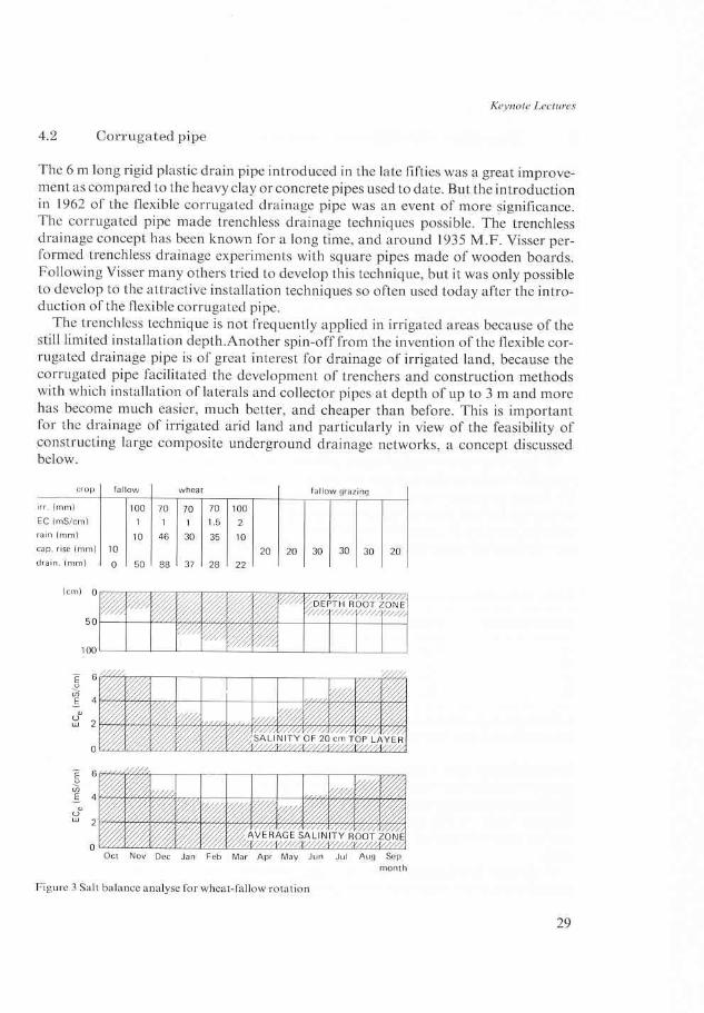
2. The second example refers to the question whether and to what extent the designed system is able to reduce and control soil salinity. It is possible to calculate the leach- ing requirement with one of the available formulae and to check whether this requir- ement is met during the irrigation period. This, however, is a rather arbitrary meth- od which does not take into account that the salt regime in the soil is a dynamic process and that a lack of leaching in one period may be compensated by an excess in other periods. A better approach is to analyse the salt balance in the soil through- out the entire cropping cycle, which may be one or more years. The computer is an excellent tool for these salt simulation studies. It analyses and processes rapidly the complex water and salt movements in the soil. An example of a salt balance analysis for a two-year crop rotation is presented in Figure 3.
These examples concern relatively simple computer applications. There are many other possibilities with various degrees of complexity. Much basic research has already been done in this field and is or soon will be available for practical application. At the International Seminar on Land Drainage held in Helsinki in 1986, I 1 of the total 36 presented papers dealt with computer applications for drainage research and design. Promising simulation models of the saturated soil water conditions throughout the cropping cycle and depending on rainfall, evapotranspiration and drainage conditions, are already available.
Developments in computer application in drainage will continue and proceed rapid- ly. After a number of years the approach, the techniques, and the procedures of drain- age design may be quite different to those of today. But common sense and good field experience will remain essential tools for the new computerized designer as much as they were for the drainage engineer in the past.
28
Keynote Lectures
5 Complete underground systems
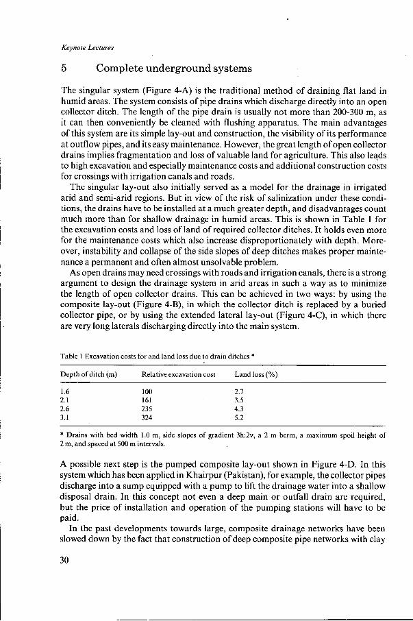
The singular system (Figure 4-A) is the traditional method of draining flat land in humid areas. The system consists of pipe drains which discharge directly into an open collector ditch. The length of the pipe drain is usually not more than 200-300 m, as it can then conveniently be cleaned with flushing apparatus. The main advantages of this system are its simple lay-out and construction, the visibility of its performance at outflow pipes, and its easy maintenance. However, the great length of open collector drains implies fragmentation and loss of valuable land for agriculture. This also leads to high excavation and especially maintenance costs and additional construction costs for crossings with irrigation canals and roads.
The singular lay-out also initially served as a model for the drainage in irrigated arid and semi-arid regions. But in view of the risk of salinization under these condi- tions, the drains have to be installed at a much greater depth, and disadvantages count much more than for shallow drainage in humid areas. This is shown in Table 1 for the excavation costs and loss of land of required collector ditches. It holds even more for the maintenance costs which also increase disproportionately with depth. More- over, instability and collapse of the side slopes of deep ditches makes proper mainte- nance a permanent and often almost unsolvable problem.
As open drains may need crossings with roads and irrigation canals, there is a strong argument to design the drainage system in arid areas in such a way as to minimize the length of open collector drains. This can be achieved in two ways: by using the composite lay-out (Figure 4-B), in which the collector ditch is replaced by a buried collector pipe, or by using the extended lateral lay-out (Figure 4-C), in which there are very long laterals discharging directly into the main system.
Table 1 Excavation costs for and land loss due to drain ditches *
Depth of ditch (m) Relative excavation cost Land loss (%)
1.6 1 O0 2.1 2.1 161 3.5 2.6 235 4.3 3.1 324 5.2
* Drains with bed width 1.0 m, side slopes of gradient 3h:2v, a 2 m berm, a maximum spoil height of 2 m, and spaced at 500 m intervals.
A possible next step is the pumped composite lay-out shown in Figure 4-D. In this system which has been applied in Khairpur (Pakistan), for example, the collector pipes discharge into a sump equipped with a pump to lift the drainage water into a shallow disposal drain. In this concept not even a deep main or outfall drain are required, but the price of installation and operation of the pumping stations will have to be paid.
In the past developments towards large, composite drainage networks have been slowed down by the fact that construction of deep composite pipe networks with clay
or concrete pipes was difficult and hence costly. However, as mentioned above, con- struction problems could be solved to a great extent due to the introduction of corru- gated drainage pipe, which also reduces the risk of silting up and need for maintenance. We therefore expect that in irrigated arid regions the construction of extended under- ground pipe drainage networks to minimize the need for deep, impractical, open drains will find more and more support and application in coming years. The final target, and one which is believed attainable in the future, is an almost fully underground pipe drainage network. With the aid of reliable and payable mineral or synthetic filters this network should be practically maintenance free.
6 Discussion of criteria
6.1 Formulation of requirements
The required performance of a groundwater drainage system can be defined by the combination of the minimum groundwater depth to be maintained in the critical peri- ods, and the amount of excess groundwater to be drained during those periods. This requirement formulation is very appropriate and commonly applied to drainage in relation to irrigation and salt control. The quantity to be drained is predictable and to a certain extent controllable, and is related to irrigation losses, seepage supplies and leaching requirements. The minimum groundwater depth to be maintained is relat- ed to avoiding damage by waterlogging and by capillary salinization. Waterlogging and capillary salinization, however, refer to different critical periods of the cropping cycle, namely the irrigation and the fallow periods. This implies that there are two
31
I
rlonrh
Keynote Lectures
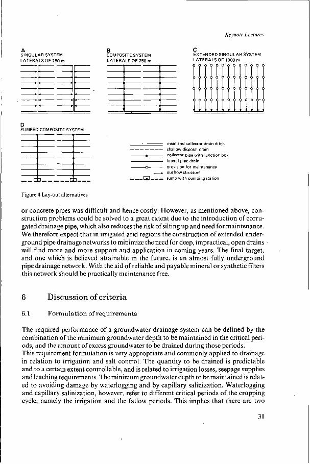
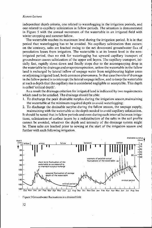
independent depth criteria, one related to waterlogging in the irrigation periods, and one related to capillary salinization in fallow periods. The situation is demonstrated in Figure 5 with the annual movement of the watertable in an irrigated field with winter cropping and summer fallow.
The watertable reaches its maximum level during the irrigation period. It is in that period that waterlogging has to be avoided. No capillary salinization then occurs; on the’contrary, salts are leached owing to the net downward groundwater flux of percolation losses from irrigation. The watertable is at its lowest level in the non- irrigated period, thus no risk for waterloggïng but upward capillary transport of groundwater causes salinization of the upper soil layers. The capillary transport, ini- tially fast, rapidly slows down and finally stops due to the accompanying drop in the watertable by drainage and evapotranspiration, unless the watertable in the fallow land is recharged by lateral inflow of seepage water from neighbouring higher areas or adjoining irrigated land, both common phenomena. In that case the role of drainage in the fallow period is to intercept the lateral seepage inflow, and to keep the watertable at such a depth that the capillary rise is considered negligible or acceptable. This depth is called ‘critical depth’.
As a result the drainage criterion for irrigated land is indicated by two requirements which need to be satisfied. The drainage should be able: 1. To discharge the peak drainable surplus during the irrigation season,maintaining
the watertable at the minimum required depth to avoid waterlogging; 2. To discharge the drainable surplus during the fallow season, the: seepage supply,
maintaining with the watertable at the depth needed to avoid capillary salinization. It should be noted that in fallow periods and even during each interval between irriga- tions, salinization of surface layers by a redistribution of the salts in the soil profile cannot be avoided, whatever the depth and intensity of the drainage system might be. These salts are leached prior to sowing at the start of the irrigation season and further with each following irrigation.
drainable surplus (mm) __r...
I wheat I fallow I beneem cotton
20 30
20
40 I ,
- example of possible actual fluctuations of the watertable +
’ ’ !! b r, I
60 - short term fluctuation of the
tertable as corresponding drainable-surplus-recharge
80
1 O0
120 of the watertable
140
160
al fluctuation of average
Oct Nov Dec Jan Feb Mar Apr May Jun Jul Aug Sep Oct Nov Dec Jan Feb Mar Apr Mey Jun Jul Aug Sep
Figure 5 Groundwater fluctuations in a drained field I
Keynote Lectures
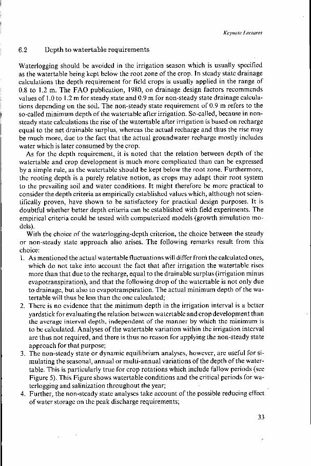
6.2 Depth to watertable requirements
Waterlogging should be avoided in the irrigation season which is usually specified as the watertable being kept below the root zone of the crop. In steady state drainage calculations the depth requirement for field crops is usually applied in the range of 0.8 to 1.2 m. The FAO publication, 1980, on drainage design factors recommends values of 1 .O to 1.2 m for steady state and 0.9 m for non-steady state drainage calcula- tions depending on the soil. The non-steady state requirement of 0.9 m refers to the so-called minimum depth of the watertable after irrigation. So-called, because in non- steady state calculations the rise of the watertable after irrigation is based on recharge equal to the net drainable surplus, whereas the actual recharge and thus the rise may be much more, due to the fact that the actual groundwater recharge mostly includes water which is later consumed by the crop.
As for the depth requirement, it is noted that the relation between depth of the watertable and crop development is much more complicated than can be expressed by a simple rule, as the watertable should be kept below the root zone. Furthermore, the rooting depth is a purely relative notion, as crops may adapt their root system to the prevailing soil and water conditions. It might therefore be more practical to consider the depth criteria as empirically established values which, although not scien- tifically proven, have shown to be satisfactory for practical design purposes. It is doubtful whether better depth criteria can be established with field experiments. The empirical criteria could be tested with computerized models (growth simulation mo- dels).
With the choice of the waterlogging-depth criterion, the choice between the steady or non-steady state approach also arises. The following remarks result from this choice: 1. As mentioned the actual watertable fluctuations will differ from the calculated ones,
which do not take into account the fact that after irrigation the watertable rises more than that due to the recharge, equal to the drainable surplus (irrigation minus evapotranspiration), and that the following drop of the watertable is not only due to drainage, but also to evapotranspiration. The actual minimum depth of the wa- tertable will thus be less than the one calculated;
2. There is no evidence that the minimum depth in the irrigation interval is a better yardstick for evaluating the relation between watertable and crop development than the average interval depth, independent of the manner by which the minimum is to be calculated. Analyses of the watertable variation within the irrigation interval are thus not required, and there is thus no reason for applying the non-steady state approach for that purpose;
3. The non-steady state or dynamic equilibrium analyses, however, are useful for si- mulating the seasonal, annual or multi-annual variations of the depth of the water- table. This is particularly true for crop rotations which include fallow periods (see Figure 5) . This Figure shows watertable conditions and the critical periods for wa- terlogging and salinization throughout the year;
4. Further, the non-steady state analyses take account of the possible reducing effect of water storage on the peak discharge requirements;
33
Keynote Lectures
5. The non-steady state approach is thus preferable in situations with significant sea-
The watertable should be kept below the ‘critical depth’ in the fallow season which in general terms is defined as the depth at which the upward capillary flow becomes negligibly small, although there is no precise definition of what rate is to be considered negligible. The critical depth is related to the type of soil and is usually taken in the range 1.4 m (for soils with fine and coarse textures) to 1.7 m (for soil with a medium texture) (FAO 1980). The critical depth is an essential design parameter which deter- mines the minimum depth at which drains are to be installed in irrigated land. Some additional remarks on proper application of this design parameter are relevant here: 1. The critical depth is only relevant as a drainage criterion in situations with seepage.
Without seepage the watertable will automatically drop in the fallow period to below the critical depth (even without drains) as a result of any evapotranspiration and natural drainage. Seepage to fallow land is, however, a common phenomenon, as discussed before.
2. In the case of intensive cropping and more or less continuous irrigated land, the critical depth also has no practical meaning. This explains that in the Egyptian Nile delta, with a more than 200% cropping intensity, drains are installed at relative- ly shallow depths of 1.2 to 1.5 m, compared to depths of 1.7 to 2.2 m applied in Iraq and Pakistan;
3. The critical depth has been related to type, or better, the capillary properties of the soil. It should, however, also be related to the length of the fallow period and the evapotranspiration in that period. If the given values of 1.4 to 1.7 m refer to long summer fallows in extreme hot climates (Iraq and parts of India and Pakistan), then smaller values could be applied for winter fallows, short summer fallows and summer fallows in less extreme climates (Tunisia, Morocco, Algeria). It is therefore suggested that the critical depth design parameter must be redefined in terms of the depth of the watertable where the capillary soil water transport to the surface, totalized over the entire fallow period, should not exceed a certain established limit. Apart from soil type, the totalized capillary water transport is also related to the length of the fallow period and its climate, for which the totalized potential evapora- tion of the fallow period might serve as a yardstick.
sonal watertable fluctuations.
6.3 The required discharge rate
The required discharge rate, also called the drainage coefficient, is the rate required to discharge the drainable surplus in the critical periods. The drainable surplus in the irrigation season is composed of leaching water, irrigation losses, excess rainwater, canal seepage, and seepage from neighbouring areas. In the fallow season the drainable surplus consists of seepage water only. The drainable surplus is usually determined by means of soil water balance studies. The different components of the drainable surplus will be examined.
The irrigation component of the surplus consists of percolation losses which are related to the irrigation method and to the efficiency of the field water management.
34
Keynote Lectures
1 L 1 .
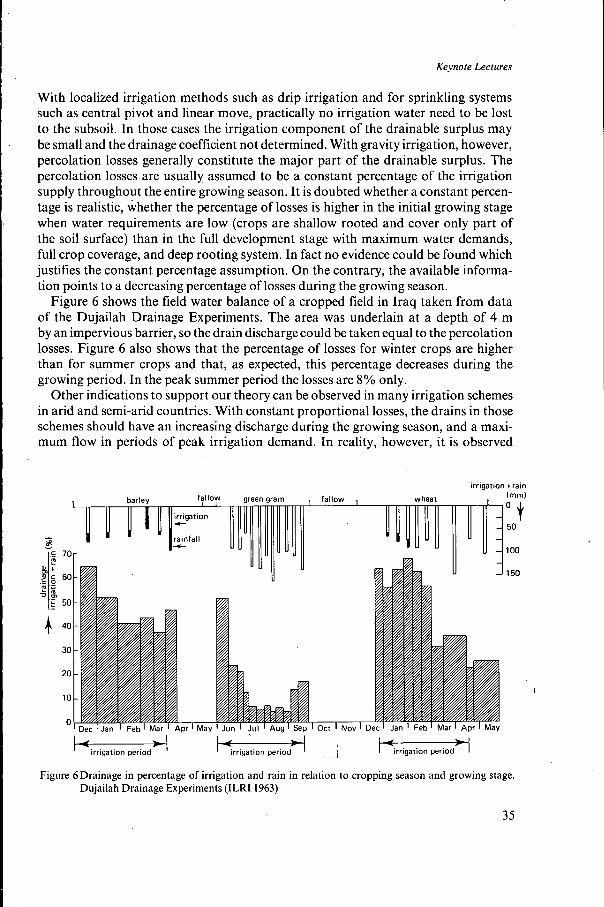
With localized irrigation methods such as drip irrigation and for sprinkling systems such as central pivot and linear move, practically no irrigation water need to be lost to the subsoil. In those cases the irrigation component of the drainable surplus may be small and the drainage coefficient not determined. With gravity irrigation, however, percolation losses generally constitute the major part of the drainable surplus. The percolation losses are usually assumed to be a constant percentage of the irrigation supply throughout the entire growing season. It is doubted whether a constant percen- tage is realistic, whether the percentage of losses is higher in the initial growing stage when water requirements are low (crops are shallow rooted and cover only part of the soil surface) than in the full development stage with maximum water demands, full crop coverage, and deep rooting system. In fact no evidence could be found which justifies the constant percentage assumption. On the contrary, the available informa- tion points to a decreasing percentage of losses during the growing season.
Figure 6 shows the field water balance of a cropped field in Iraq taken from data of the Dujailah Drainage Experiments. The area was underlain at a depth of 4 m by an impervious barrier, so the drain discharge could be taken equal to the percolation losses. Figure 6 also shows that the percentage of losses for winter crops are higher than for summer crops and that, as expected, this percentage decreases during the growing period. In the peak summer period the losses are 8% only.
Other indications to support our theory can be observed in many irrigation schemes in arid and semi-arid countries. With constant proportional losses, the drains in those schemes should have an increasing discharge during the growing season, and a maxi- mum flow in periods of peak irrigation demand. In reality, however, it is observed
-
k * r
fallow I barley
irrigation
rainfall
c
-c
70 r
green gram , irrigation train
(mm)
50
1 O0
150
50
40
30
20
10
O
Keynote Lectures
that drain discharges do not increase. On the contrary, drains often have minimum flow in periods of peak irrigation demand.
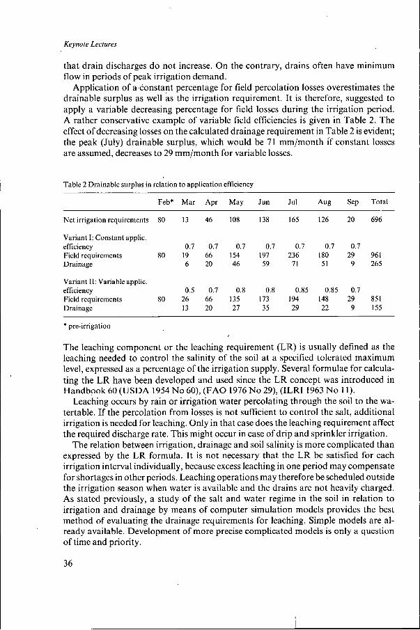
Application of a constant percentage for field percolation losses overestimates the drainable surplus as well as the irrigation requirement. It is therefore, suggested to apply a variable decreasing percentage for field losses during the irrigation period. A rather conservative example of variable field efficiencies is given in Table 2. The effect of decreasing losses on the calculated drainage requirement in Table 2 is evident; the peak (July) drainable surplus, which would be 71 "/month if constant losses are assumed, decreases to 29 "/month for variable losses.
Table 2 Drainable surplus in relation to application efficiency
The leaching component or the leaching requirement (LR) is usually defined as the leaching needed to control the salinity of the soil at a specified tolerated maximum level, expressed as a percentage of the irrigation supply. Several formulae for calcula- ting the LR have been developed and used since the LR concept was introduced in Handbook 60 (USDA 1954 No 60), (FAO 1976 No 29), (ILRI 1963 No 1 1 ) .
Leaching occurs by rain or irrigation water percolating through the soil to the wa- tertable. If the percolation from losses is not sufficient to control the salt, additional irrigation is needed for leaching. Only in that case does the leaching requirement affect the required discharge rate. This might occur in case of drip and sprinkler irrigation.
The relation between irrigation, drainage and soil salinity is more complicated than expressed by the LR formula. It is not necessary that the LR be satisfied for each irrigation interval individually, because excess leaching in one period may compensate for shortages in other periods. Leaching operations may therefore be scheduled outside the irrigation season when water is available and the drains are not heavily charged. As stated previously, a study of the salt and water regime in the soil in relation to irrigation and drainage by means of computer simulation models provides the best method of evaluating the drainage requirements for leaching. Simple models are al- ready available. Development of more precise complicated models is only a question of time and priority.
36
Keynote Lectures
The seepage component is the most difficult one of the series of drainable surplus. It includes canal seepage, seepage from irrigated to fallow land, and groundwater mo- vement at greater depth and over larger distances from high land to areas of depression. The latter is responsible for the differences in natural drainage and seepage conditions.
Canal seepage is a local problem. It may be accounted for by designing seepage interceptor drains, and it may also be accounted for in the drainage coefficient by assuming an uniform seepage rate over a strip of land on both sides of the canal. Both approaches are not very accurate but considered satisfactory, in view of the low accuracy with which the canal seepage losses are usually known. To estimate canal losses and their distribution, flow analyses with two-dimensional numerical computer models are nowadays applied.
Seepage from irrigated to fallow land is very common and is the main cause of salinization in fallow land. As is the case with canal seepage, quantification of this seepage is difficult. It is usually taken as an estimated uniform rate for the area con- cerned.
In areas underlain by a highly transmissible aquifer, the natural drainage and seep- age conditions resulting from lateral groundwater movements may have a great effect on the drainable surplus and on the discharge criterion for design. Areas with natural drainage have a small drainage coefficient or require no drainage at all. Areas with seepage have an increased surplus and are moreover subject to salinization if not pro- perly drained. For a quantitative analysis of the natural drainage and seepage condi- tions in areas where these are considered of importance, groundwater modelling is the only proper solution, especially as drainage/seepage conditions will vary through- out the year. Groundwater modelling, however, is still quite a complicated and costly exercise, and is preferably done as a part of an integrated regional groundwater man- agemen t study.
An example of groundwater modelling for assessment of drainage coefficients is the 250000 ha SCARP VI project (Figure 7), in the central part of the Indus Basin in Pakistan. This project area is underlain with a highly permeable aquifer. The lateral groundwater movement provides for natural drainage in some parts of the project area, and causes serious drainage needs in other parts. A computer model study, aimed at optimal integrated ground and surface water management, and the determination of the areas in need of drainage and the regional variation in drainable surplus, was developed and calibrated with historical watertable records. Some results of the model study are given in Figure 7 (WAPDA 198 1).
6.4 The drain depth
The drain depth refers to the installation depth of underground drains or to the depth to the watertable in open drainage ditches. The drain depth is directly related to the drainage criterion. The drains should at least be installed below the required level of the groundwater table during the irrigation season or below the critical depth if the criterion of the fallow season is to be met. Drains are usually installed deeper than the required minimum. The optimum drain depth is to be found as a compromise
37
Keynote Lectures
POLYGON NETWORK OF SCARP V I AREA FOR GROUNDWATER MODEL
_ _ _ _ - _ boundary project area i* DRAINABLE SURPLUS IN SALINE GROUNDWATER AREA DETERMINED BY MODEL STUDY
20 30 40 50 km
drainable surplus (mm/davl
- 0 - 1
-1 1 - 2
watertable In fresh water zone controlled by skimming irrigation Welk
Figure 7 Groundwater modelling for determining drainable surplus
between the advantages and disadvantages of a greater depth. Advantages of deep drains are greater hydraulic head and more storage capacity
in the soil, both resulting in larger spacings and thus less length of drain per unit area. Another advantage is that deep drains will discharge continuously, and thus may have less risk of silting up. Disadvantages of deep drainage are increased technical problems in proper installa- tion, increased costs of installation and materials per unit length of lateral, and possible costs for deepening the main outfall system and pumping. The installation depth of lateral drains has been steadily increasing since 1960, and installation of deep drainage
38
Keynote Lectures
Importance of monitoring
It will have become clear that there are still incomplete answers and thus further re- search is required into fundamental questions such as relation of drainage with crop yield, choice of design criteria, salt regime and drainage. Research is still necessary for testing and improvement of current survey and design techniques, drainage mater- ials, construction equipment and installation methods. Research is carried out in the laboratory, on experimental fields and with simulation computer models. Another very valuable research instrument is monitoring the performances of the drainage scheme in operation. Monitoring is a direct way of measuring the effect of the imple- mented works on crops, salinity and groundwater: pre and post-project conditions as well as actual and forecasted performances can be compared; operation and main- tenance aspects studied; costs and benefits evaluated; and design and construction shortcomings identified.
Unfortunately monitoring has not generally been applied to date. Reliable monitor- ing of drainage schemes is almost non-existent. Monitoring should therefore be pro- moted in the interest of operational and fundamental drainage research, and also for proper operation and maintenance of the drainage works. The drainage and project authorities responsible, have to be convinced of the importance of monitoring. Moni- toring should already receive proper attention in the study and design phase of a drain- age project. A detailed monitoring programme, and the requirements of staff, equip- ment and funds, should be part of the project planning documents. The drainage design should take monitoring into account by providing adequate facilities for data collec- tion.
Monitoring is considered costly because of the staff required for field work and data processing. However, monitoring nowadays can make use of modern technology and this is very advantageous. Not only the staff requirements for data collection can be greatly reduced but also better data-processing techniques can be applied with less staff. Of the many possible applications of modern technology for monitoring of drainage schemes the following are mentioned: - The use of remote-sensing images for recording changes in soil water and salt condi-
tions and developments in land use and crop growth; - The use of automatic electronic recorders for all kinds of data collection. These
recorders are preferably fitted with facilities to transmit recorded data directly to the computer processors and eliminate the need for manual input. A good example of such equipment is the ‘Preslog’, a small battery powered instrument which is very easy to install and can register and store in a memory block (Eprom) hourly
I
has become better and cheaper. There is an economic optimum drain depth, corres- ponding to minimal costs per unit area. This depth has recently been analysed (Bou- mans and Smedema 1986), and corresponds rather well with the depth ranges actually applied in humid as well as arid regions. We expect that the existing trend towards deeper drainage will continue, because further improvements in the construction tech- nology will reduce the disadvantages of deeper installation.
39
Keynote Lectures
records of waterlevels or rainfall for one year. The Eprom can be read by a computer which also is used for data processing and filing;
- The use of computers for data filing, data processing and reporting. The great ad- vantage of computers compared to traditional data processing by hand is obvious.
Monitoring as well as processing and evaluation of data requires highly qualified staff. It may therefore be practical to carry out monitoring in collaboration with a specialized drainage research institute which can advise on the kind and method of data collection and on the equipment required, and can participate in data processing. The different objectives of monitoring may then be served in the best way. A good example of such a specialized institute is the ‘Drainage Research Institute (DRI)’ in Egypt which is an agency of the Ministry of Irrigation.
8 I Final remarks and conclusions
In this paper we have discussed the horizontal drainage of irrigated arid lands which is different from the drainage in humid temperate areas in many ways. Developments with respect to design, construction, and research have been discussed. Present design practices, criteria and standards have been critically examined.
The major conclusions are summarized below in the form of statements presented for further discussion. 1. Drainage or better subsurface drainage for irrigated arid land is very different from
subsurface drainage in humid areas, with respect to the objectives, requirements and criteria, field investigations, design options, construction practices, equipment and materials. It is questionable whether the difference between drainage in humid and arid regions is sufficiently reflected in the structure and programme of the International Post-Graduate Course on Land Drainage;
2. Computer drainage applications have been started and are expected to increasingly contribute to drainage research and to the introduction of improved and automated design procedures for the drainage of irrigated land. Particularly simulation models for studying the salt and water regimes as related to soil, irrigation and drainage will be important in these respects. Simulation models have the advantage that they can be adjusted to local conditions, since they can be calibrated with actual field data;
3. Monitoring is a valuable tool for fundamental and operational drainage research, and for controlling the proper functioning of the system. Monitoring should be included in the design and operation of any drainage scheme. Monitoring can make use of modern electronic equipment. Monitoring should, if possible, be coordinated by a national drainage research organization;
4. With respect to lay-out and construction of drainage systems, the projected devel- opment is an ongoing trend towards extended underground piped drainage net- works in order to minimize length of deep open drains. The final target being an almost fully underground system and practically maintenance free;
5. The drainage requirements for the irrigation and fallow seasons should be clearly distinguished. The irrigation season requirements must be related to waterlogging
40
Keynote Lectures
and leaching, and the fallow season requirements related to intercepting seepage and maintaining the watertable at the critical depth. The critical depth must be defined in terms of the depth for which the totalized upward capillary soil water flux during the fallow period does not exceed a certain norm value;
6 . The common practice by which field percolation losses and, consequently the drain- able surplus are taken as proportional to the irrigation supply may lead to an overes- timation of the drainage discharge requirement. The percentage of losses is general- ly higher in the initial growing stage than in the period that crops reach their full development. Application of decreasing losses (or increased field efficiencies) dur- ing the growing season is therefore recommended in water balance studies for as- sessing drainable surplusses;
7. The relation between leaching requirement and drainage can best be analysed by means of salt regime simulation models;
8. In schemes with a highly permeable aquifer, groundwater modelling may be needed for a proper assessment of both the natural drainage conditions and the spatial variations in drainage requirements and drainable surplusses;
9. Drain installation depth has the tendency to increase as a result of improved con- struction technology.
References
Boumans, J.H. and L.K. Smedema, 1986. Derivation of cost-minimizing Depth for Lateral Pipe Drains.
Ernst, L.F. 1986. Computation of groundwater flow between parallel open conduits (in Dutch with English
Euroconsult, 1985. Drainage of gypsiferous soils in the Carlsbad Irrigation District. New Mexico, USA.
FAO 1976. Water quality for agriculture. FAO Irr. and Drain Paper 29. R.S. Ayers and D.W. Westcot,
FAO 1980. Drainage design factors. FAO Irr. and Drain Paper 38, Rome. Hooghoudt, S.B. 1940. Dewatering through parallel drains (in Dutch). Versl. Landb. Ond. 4651 5~707.
Helsinki 1986. Proceeding of International Seminar on Land Drainage, J. Saavalainen, P. Vakkilainen,
ILRI, 1963. Reclamation ofsalt affected soils in Iraq. P.J. Dieleman edit. Publication 1 1 , ILRI Wageningen. Luthin, J.N. ed. 1957. Drainage of Agricultural Lands. American Soc. of Agr. Madison, Wisconsin. NN, 1958. Niyala Basin Archeological Project. Salinity and Irrigation Agriculture in antiquity. Report
NESPAK/ILACO, 198 I . Panjnad-Abbasia Salinity Control and Reclamation Project (SCARP VI): Final
Reeve, R.C., L.E. Allison and D.F. Peterson, 1948. Reclamation of Saline Alkali soils by leaching. Delta
Toksöz, S and O. Kirkham, 1971. Steady drainage of layered soils I and 11. Irr. and Drain of the Div.
U.S.D.A. 1954. Diagnosis and improvement of saline and alkali soil. Handbook 60. U.N. 1985. Studies for the use of saline water in command'areas of irrigation projects. Haryana, India. Wilcocks, W. and J.I. Craig, 1983. Egyptian Irrigation. 3rd ed. London. WAPDA/ILACO 1985. East Khairpur Tile Drainage Project. Project Completion Report.
Agricultural Water Management, 12 (1986)41-51.
summary). Comm. Hydr. Res. TNO Proc.: 48-68. The Hague.
Report of field visit by W.J. van Diest.
Rome.
Alg. Landsdrukkerij, Den Haag.
editors. Helsinki University of Technology, Dep. Civ. Eng.
on essential results June 1, 1957 to June I , 1958.