48

8 8~ 12 1~~25 ~ 1210 w MIl 10 W iiIl I~~ wW w I~ 2w I ~ I~ ~ Iipound II II ampI 40 20 i I~ 11 ~ ~ - - -- 1111118
11111125 1111114 1111116 11111125 1111114 16
o MICROCOPY RESOLUTIOi1 TEST CHART MICROCOPY RESOLUTION TEST CHART
NATIONAL BUREAU OF STANDARDS-1963-A NATIDNAL BUREAU OF STANDARDS-1963-A
t
Technical Bulletin No 1065 Se1)tenbel 1952
Drainage Investigation ~Iethods for
Irrigated Areas inWestern United States
By WILLIAM V DONNAN dmilLage engilleel and
GEORGE B BRADSHAW irrigation eJ1gineer
Soil C011HTation Senice2
CONTENTS Png( ~ Pngc
bull Introduction 1 Existing (lata 26 Basic drainage information 2 Observation wells bullbullbull 26 Preliminary investigations 3 Piczometcrs 27 G d f t t 4 Yntcl-Soulca sUlvay 38
roun eSur ace 1l1ves 19a IOns bull _ Sources of watrr 39 Soil investigations bull b Salinity of water 42
Reyic of cxisting data 7 Types of drainagc systcms and Field mcasuremcnts and structures 42
observations bull 7 Open drains 43 Soil-pcrmeability Covered drains 44
determinations 17 Wells and sumps 44 Water-table investigations 26 Literature cited bull 45
INTRODUCTION
Drainage problems in the irrigated areas of the West differ widely because of the varied nature of the physical land and hydroshylogic conditions There are therefore no fixed short-cut methods of investigation that are uniformly applicable to the analysis and solution of all drainage problems under all conditions in all areas Some problems are fairly simple and their solution is quickly apparent Others require only limited investigation Generally however the soils waters and cropping and irrigation practices vary so greatly both individually and in their total effect that a complete and thorough evaluation is needed to determine the speshycific causes of undesirable drainage conditions and their correcshy
1 Submitted for lubliclltian Mu~ ~9 1052 bull
bull bull This study was carried out by the Research Division o( Irrigulian Engineering and
Water Conservation Soil Conservation Service in cnoJ)crnlion with the Imperinl Irrigation District State of Califarnill
2 TECHNICAL llULLETIN NO 1065 U S DEPT OF AGRICULTURE
tion Holes must be bored observation wells installed soils examined and hydrologic measurements taken Every source of bull information relating to the problem must be explored and the information analyzGd
Practical land drainage rests upon some fairly simple principles a complete understanding of which is required for the practical solution of the many complex drainage problems encountered The actual solution of these problems presents technical difficulties of a high order This bulletin outlines methods for conducting drainshyage investigations in irrigated areas of western United States It presents a description of equipment and techniques that have been found useful in the study of ground-water problems together with a discussion of their application It sets forth procedures for analyzing and evaluating the essential information and organizing it for effective use in the solution of drainage problems
BASIC DRAINAGE INFORMATION
The basic infolmation important in any drainage investigation deals primarily with the follo-wing four elements Topography soils water tables and water source including the quality and quantity of water These are not mentioned in nner of imporshytance nor should they necessarily be investigated in the order given Vhen the specific problem and its cause are obvious as for example in the case of waterlogging caused by canal seepage attention would need to be focused mainly on the water-source factor
The more complex problems require an orderly procedure of bull investigation and analysis for their solution For such problems answers must be obtained for questions like the following (1) Is there a suitable outlet for the drainage water (2) Can the excess water be removed readily from the root zone of the soil (3) Does the water have its source in rainfall irrigation seepage or arteshysian flow (4) How much water must be removed (5) What type of drainage system will give the best results
Such questions are fairly typical of those arising in the analysis 2lnd evaluation of the four basic elements of drainage infol lation_ A few examples of how differences in topography soil and hydroshylogic conditions affect the selection of drainage systems and strucshytures ill actual drainage practice will illustrate the importance anci use of such information
The to]JogJaJhll often indicates the most suitable type of drainshyage The topographic survey may reveal that there is a lack of natural outlets for drainage water or that the terrain is unsuited for the construction of open eh-ains except at excessive cost Een though the soil may be drainable the configuration of the land may be such as to prevent the ultimate djsposal of the drainage water ill a feasible manner The basin type of tOl)ography lends itself well to pumping for drainage Disregarding other factors flat slopes lend themselvep well to tiling on a grid system whereas swales a11d benches suggest the use of interceptor lines Pockets requiring drainage are usually ber-t drained by sumps The extent bull
DRAINAmINVESTIGATION METHODS FOR IRRIGATED AREAS 3
and effectiveness of existing canal systems often suggest the best location for open drains
The soils of the problem area influence the choice of a drainage system in many ways The sequence of permeable and impermeable strata in the area and the ability of the separate layers to transmit water largely determine both the type of system that should be installed and its design Open drains at I-mile intervals may be adequate for draining areas vf extremely porous subsoils whereas a relatively heavy soil might require tile lines spaced not more than 100 feet apart Lack of drail1able strata in the 4- to 8-foot zone may make drainage by tile lines unfeasible Thus the size depth and spacing of tile lines the size depth and capacity of drainage wells and the location and depth of sumps all depend on the results of the soil survey and related geologic infurmation
The height movement and cyclic trends of the wcttr tCLble deshytermine or affect the choice of drainage measures For example artesian pressure areas are extremely difficult to drain with tile lines and relief pumps usually are necessary to relieve the pressure from below Stream lines of flow indicate the points where seepshyage can be interceped to advantage
bull
The 1(((ter-So1LTce S1u11ey indicates the amount of water for which drainage must be provided and thenatule of its source Vhere rainfall is a factor in the drainage prob1em open drains usually are essential for the removal of excess surface flow In arid western areas in which no excessive rainfall volumes are involved pumping may be the solution to the drainage problem Vater-quality determinations are important in areas lacking adeshyquate water supplies If drainage water is of good quality for eXl1mple plans can be made to 1e-use it for irrigation purposeF Obviously if a drainage system can be made to produce usable water at the points where it is needed the cost of drainage can be greatly reduced or almost completely written off
In obtaining the essential data on these matters full advantage should be taken of any pertinent information resulting from previshyous surveys that have been made of the topography soils water tables and water sources in the problerl1 area and its general vicinity
PRELIMINARY INVESTIGATIONS
Preliminary investigations should be made before undertaking intensive field studies Such investigations include a review of all existing written tabular and graphic data pertaining to drainage problems in the area discussions with local people and a field reconnaissance of the problem area
The availability of adequate contour maps and aerial IJhotoshygraphs of the area should be explored in order to determine the need for additional topographic surveys Existing aerial photoshygraphs may reveal the location of seep areas and saline or alkaline spots and may provide clues to the location of water sources The degree of crop growth shown on such photographs may indIcate the presence of underground clay barriers or sand pockets that
bull affect underground drainage Early engineering reports relatillg
4 TECHNICAL BULLETIN NO 1065 U S DEPT OF AGRICULTURE
to the area involved contain much useful information Almost all of the valleys in the western United States have been surveyed or
I investigated at some time in the past to determine the possibility bull of reclaiming land or expanding the size of irrigated areas
Other reports such as geological papers publications of the United States Bureau of Mines water-supply bulletins reports of experiment station studies soil surveys and State engineering publications furnish valuable information Such publications and reports generally may be found in public libraries in State county or city engineers offices or in agricultural college files
A reviev of the history of a drainage problem may reveal that the area involved was always poorly drained and that unfavorable conditions have merely been aggravated in more recent times by improper methods of land development The problem may have developed as a result of the poor location or faulty design of a canal dam or reservoir It may be the result of a change in crop production the drilling of new wells or the abandonment of old ones The occurrence of a drainage problem or the growing severshyity of such a problem may be coincident with cyclic peaks of preshycipitation or with an increase in water supply following the expanshysion of adjacent irrigated areas A gradual deterioration in drainage conditions over a period of years may be due to regular use of too much irrigation water Many of the historical circumshystances mentioned may indicate that the principal factor responshysible for drainage conditions is the source of the water
The preliminary field reconnaissance is an essential step in the investigation since it forms the basis of all further investigations bull It consists of a comparatively rapid examination of conditions on the ground preferably with a person familial with the area It should be sufficiently thorough to furnish the following informashytion
(1) Number and general location of natural waterways (2) Location and condition of possible drainage outlets (3) Location and general characteristics of canals laterals
wells ponds springs reservoirs and other wat~r sources (4) Location and general charact~ristics of drains adjacent to
the problem area including existing tile lines and surface drains (5) The general characteriRtics of the irrigation practices in
current use status of land leveling grades and mode and efficiencyof water application
(6) The obvious topographic features such as dunes benches pockets and outcrops
(7) The approximate present water-table level and its fluctuashytions
(8) Present cropping practices condition of crops and changesfrom previous years
GROUND-SURFACE INVESTIGATIONS
A ground surface investigation consists mainly of a topographic survey of a proposed drainage area to determine the surface conshyfiguration including the RUlface slopes the direction of natural drainage and potential drainage outlets This survey gives a clue bull
DRAINAGEl INVESTIGATION METHODS FOR IRRIGATED AREAS 5
to the type of drainage needed and the extent to which the ecoshynomic feasibility of this type is affected by the presence ofnatural grades outlets and favorable topography-all of which help to reduce drainage costs It leveals the status of land preparation in the irrigated areas and discloses the places where poor land levelshying instead of poor drainage may be the cause of crop failure It gives more positive information upon which to base specific drainshyage plans and proposals than is obtained by visual inspection in a prelimirlary reconnaissance
A necessary preliminary of a ground-surface investigation is an analysis of all existing maps charts or aerial photographs of the area in question Aerial photographs and United States Geologshyical Survey quadrangle maps are hel pful in locating possible drain outlets and boundaries of affected areas A comparison of old aerial photographs with more up-to-date pictures sometimes reshyveals differences in degree of crop growth which offer clues to the nature and development of the drainage problem For valley-wide investigations both Geological Survey topographic maps and aerial photographs are needed to provide an over-all picture of the problem
bull
The field survey provides all the physical measurements necesshysary to map the surface configuration of the area It should estabshylish a system of bench ma~ks from which a topographic map can be made with a sufficiently small contour interval for planning the drainage system For farm or field areas the topographic map may be based on a system of grid shots on about 400-foot spacing In many mountain valley areas the topographic grid must be based upon verticai intervals rather than horizontal the vertical interval usually ranging from 2 t05 feet or more depending upon size of area and steepness of land Additional elevations at field corners and at waste and head ditches 01 canal-oater lines are useful Elevations should be obtained of all potential outlets 311d at breaks in topography and high-water elevations should be determined for the points at which (hains empty into streams
All survey information should be plotted on plan and profile sheets Although topographic maps provide the primary basis for drainage layouts profile drawingR are necesRary for planning such details as the depth slope and alinement of drains Breaks in slope benches alluvial fans canals old creek channels and other natural drainageways are important land featureR the locashytion of which may affect the solution of the drainage problem being investigated The locations of springs seeps abandoned wells or diversion points may be important keys to the solution of the probshylem
SOIL INVESTIGATION~
The soil-stratum survey which gives the location extent and physical characteristics of the various underlying soil layers is probably the most important single technical phase of the drainage investigation No drainage system can be adequately designed without a knowledge of the soil profile and the characteristics of
the subsurface strata Points which should be considered are
bull bull bull bull
bull bull bull
bull bull bull
6 TEOJlNICAL BULLETIN NO 1061gt U S DEPT OF AGRICULTURE
STRATA SURVEY GRID
A
8 0 0 0 0 t
c 0 0 0 0 0 0 0
0 0 0 0 0
E ) 0 0 0 0 0 0
F 0 0 0 0 )
GA Z 5 63 4 7 8 9
PROFILE REPRESENTATION 100 BI 8Z 83 Bmiddott B5 86 87 88 89
~ 98
96 ~ 94 iil 9Z
90
til BB
~ 86 CII
~ B4
8Z
B
LOG OF PROFILE BI PERMEAGRAPH PERMEABILITY INDEX o 2 4 6 8 10
I I JOO
~ 9B I
96 ~ 94 - 9Z 90
B8
til 86 IIiil 84
~ 8Z
c
N
100
98
96
94
92
90
88
86
04
B2
bull
bull
FmURE lmiddot-Stratum-survey diagram showing strata-survey grid profile representation log and permeagruph
7 DIlAINAGE INVESrlGNrlON IIglHODS FOIl IItIlICAflJO AlmAS
(l) Kinds of soils (2) thickness of the various strata (3) conshy
bull tinuity of str~lta and (4) position of the variolls strata with reshyspect to the ground surface and to each other
REVIEW OF EXISTING DAlA
Before a field survey of a farm district 01 valley is started a thorough review should be made of the existing soils information Sources of data include soil smveys records of borings made by public 01 private agencies and the numerous well logs commonly flled and recorded in local county court houses Other sources are reconnaissance reports of soil profiles observed in exposed ditch stream 01 riverbanks open excavations and gravel pits The technical papers of the United States Geological Smvey contain useful information on the deeper underlying strati Ocations of the earth crust a knowledge of which is vital to an understanding of local drainage problems They provide information on faulting I1ature and extent of gravel beds dip of bedrock 01 shale layers and related information on geologic structure affecting the type and design of the drainage system
FIELD lvIEASUREMENlS AND OBHERVATIONS
bull Investigations needed for planning drainage systems should take
into account the results of past soil borings and other available data Any additional soil borings needed are so located as to supshyplement the existing data Where little or n0 data are available borings should be made 011 a grid pattern designed to furnish the Heeded soil information by the lise of a minimum number of holes Since it is not always possible however to determine beforehand the exact spacing of holes needed for complete data supplemental intermediate borings may be necessary For example a continuous sand aquifer stratum which has been found regularly at a depth of 4 to 5 feet in a series of borings may be absent in the next adjashycent ones Additional borings closer to the known perimeter of the sand stratum will 1eeal its true extent
Topographic features such as canals drains washes and benches frequently influence the location of holes For example if the drainage l)roblem is caused by canal seepage one or more lines of holes at right angles to the canal will usually be required to determine the proper location fol interceptor drains Grids are generally oriented to the dominant slope They should cover not only the areas immediately aflected but also adjacent lands
The grid layout and related data are illustrated in the stratumshysurvey diagram (ng 1) lhe boring grid can be expanded 01 COl1shytra~t6d to covel any desired area but regardless of the size of area the numberliLg of the various borings locates the approximate posishytion of the various holes lhus boring B9 on the strata-survey grid is 011 horizontal line B and vertical line 9
The grid system lends itself well to graphic profile analysis since
the borings are generally in a line and the soil profiles of a particushylar series of borings hI the grid can be easily shown by means of a plof1le representation as illustrated in figure 1 A prof1le represhysentation can be made of any li1H~ of borings either horizontally or
213447-63-2
8 TfCHNIOAI BULLETIN NO 10G5 U S DEPT OF AGRICUfTURE
vertically across the grid Profiles of borings scattered at random throughout an area on the other hand are hard to line up sysshytematically bull
A profile graph of the type illush~ated shows not only the relashytion of each stratum to the others in the profile at any particular sampling point in the area but also the lateral extension of the soil strata between sampling points somewhat as if the problem area had been sliced along the line of borings In the method illustrated the various kinds of soil strata such as nne sand silty clay loam and clay are plotted to a vertical scale a11d shown by hatching stippling 01 solid blocking Colors or other distinctive marks mayalso be used for this purpose
The logs of the borings are recorded in the regular way by notes describing the various strata encountered They may also be depicted on the stratum-survey diagram in conjunction with the strata-survey grid an~ profile representation as described above
The permeagraph is a useful device for expressing the relative permeability of the various subsurface strata It provides a means also of visualizing in approximate terms the probable relative rate of water movement throughout the entire profile and the location of bottlenecks in the soil which retard or stop the free flow of water Thus a clay stratum which tends to inhibit the movement of water through the subsoil is shown by a narrow column whereshyaR a relatively permeable sand stratum appears as a wide column
EQUIPMENT
Soil-investigation equipment includes hand and power augers jetting rigs coring tubes and various kinds of laboratory appashyratus for making tests of permeability and other soil properties bull The equipment needed in making a stratum survey depends on the information required
Allge1s-Among the many types of augers used to make soil borings for drainage i11Yestigations the most common is probably the post-hole auger This tool is available with 2-inch 4-inch and 6-inch-diameter bits which can be used interchangeably on the same pipe shaft Explorations to depths of 20 to 30 feet can be made by adding extensiOllR to the shaft The larger size of bit is adapted to securing disturbed soil Ramples since the bucket-shaped bit can extract a relatively large quantity of soil from the hole In wet soil the post-hole auger type of bit is more practical than some of the small screw-type bits The orchard auger one of the various modificatiolls developed for special soil conditions is adapted for use in sandy soil The cylinder-shaped bit is 4 inches in diameter and 10 inches long and has two cutting leaves on the bottom end
Although the ordinary 5-foot soil auger equipped with a 1-inchshydiameter screw bit is widely used for making shallow borings it is unsuited for the deeper borings required in subsurface drainage survey work For such borings an adjustable-handle 9-foot auger similar to the one developed for use in drainage investigations in Imperial Valley Calif is more practical (fig 2) This tool which has a screw-type bit 1 inches in diameter is one of the best of the variOlls auger types for mapping soil strata It has a solid shaft with a -inch slot along one side The handle is fitted with bull
I
9
- ~
DRAINAGE lNVESTlGATlON METHODS FOR IHRlGATElD AREAS
bull a screw key which may be moved in and out of the slot by turning the adjusting handle This permits locking the handle at any point along the shaft Boring is started with the handle at a height of about 4 or 5 feet as the hole deepens the handle is raised on the shaft The depth of boring is indicated by marks on the shaft spaced at 1-foot intervals
Several power augers are in commercial production One type of portable digger folds into the bed of a pickup truck This machine has a 4-cycle 3-ho1sepowe1 gasoline motor mounted dilectly over a telescoping drill shaft which can be extended to 10 feet By coupling on additional shafts drilling can be still further extended to a maximum depth of 30 to 40 feet Optimum operating depths however are from 8 to 16 feet depending on the kind of soil mld the moisture conditions Drill bits range from 2 to 10 inches in diameter From four to six 10-foot holes per hour can be bored under average soil conditions Use of the portable type is limited to areas accessible to the light transportation equipment on vhic11 the device is mounted
bull
Boring with augers has several cliHadantages It is difficult to distinguish in the soil samples any thin Htrata of sand silt and clay that are 2 inches or less in thiclmess The Hamples themselves may become mixed with other soil as the auger is withdrawn Borshying is alHO Jikely to destroy the inherent soil Htructure andl11akes it difficult to identify minute soil lenses by visual inspection In saturated sand boring is mechanically difficult because material from the sides of the hole flows back into the hole andleplaces the removed soil almost as quickly as the sample is withdrawn
Jetting if8-The character of the subHoil at depths below 20 feet is important in connection with certain drainage problems especially where artesian pleSHUres may be a factor The jetting rig is probably the best type of device for logging sands and clays to depths of 20 to 100 feet (1011)3 It consists of a Hmall tube -inch to 1-inch in diameter which is forced vertically into the ground Vater is pumped into the tube under pressure The ease with which the tube passes through successive segments of the soil and the nature of the Hoil that bubbles out around the outside of the tube give a good indication of the location of sand Or clay in the profile The texture of the subsurface materials is also indishycated by the jetting pressure and rate of boring
Jetting may be difficult here caliche or other hardpans are presshyent Where extremely coarse gravels are encountered aqua-gel or drillers mud mUHt be used with the jetting water to enable the tube to penetrate the strata
Cming tubes-Neither the auger type of tool nor the jetting techniques are suitable fol obtaining soil samples intact-undisshyturbed samples-for analysis of physical and hydraulic characshyteristics and for other mmlyses h1 the laboratory For these purshyposes several inexpensive typefi of coring tubes are more suitable
rfhe Veihmeyer type of Hoil-Hnmpling tube can be used to obtain
bull cores of small diameter 111 an but extremely COinfie soils This tube ranges from 5 to 25 feet in length and con-ists of seamless steel
aUatie numbers in parenthescs Icfci to Lilclatt1lc Ciled
10 TECHNlCAL BULLETIN NO 1065 U S DEPT OF AGRICULlURE
bull
K
M bullo J--t--L
WOOD AUGER I 14 DIA FISH TAILED AND FLARED TO EXPEDITE BORING ONE SIDE OF THE AUGER CUTTING EDGE CAN BE COATED WITH HARD SURFACE ROO THIS HARD CUTTING EDGE SLOWS DOWN WEAR ON THE AUGER AND ALSO ACTS AS A SELF-SHARPENER
FIGURE 2-Imperial Valley soil auger
bull
DRAINAGE INVESTIGATION METHODS FOR IRRIGArED AREAS 11
tubing 1 inch in inside diameter fitted with a driving head and point The cutting point is made of case-hardened nickel steel and has a choke bore which permits the soil core to slide up inside the tube without serious friction The tubes are driven with a sliding hammel which fits over the top of the tube The usual practice is to drive in I-foot stages as indicated by I-foot graduations marked on the outer wall of the tube A special jack fitted with a set of grippers is used for pulling the tube however under ordinary conditions of soil moisture a jack is seldom l1eceSS~lY Figure 3 shows this tube together with driving hammer and extracting equipment
bull
FIGURE 3-Veihmeyer type of soil-sampling tube which has been driven into the soil The gLippers and jack are used to pull the tube out of the ground The hammer llsed to drive the tube is shown in foreground
Sampling by this method gives accurate plo(j)e logs since the relatively undisturbed cores clearly show the soil structure minute stratification contacts between strata and other physical soil characteristics The small diameter of the samples however preshycludes their use for laboratory tests of permeability based on unshydisturbed soil Other disadvantages of the method are the unsuitshyability of the tube for sampling strata that contain stones 01 large gravel the difficulty of securing cores below the water table and the difficulty of extracting moist sand or clay from the tubes
For sampling to depths that do not exceed 30 inches the coreshy
sampling apparatus originated at the Ohio Agricultural Experishyment Station and subsequently improved by Uhland (12) is availshyable In using this device it is necessary to dig a pit to secure sucshy
12 TECHNICAL BULLETIN NO 1065 U S DEPT OF AGRICULTURE
1
1(~
bull
FIGURE ltt-Field core-sampleI patts before assembly 1 and 2 driving assembly 3 and 6 upper and lower shoes respectively 4 extra cylindrical head for use in taking cores with jack 5 bale for pulling shoe assembly 7 aluminum cylinder fits into 3 8 shock ring fits on top of 7 0 pint carton for transporting cylinder and soil core
cessive depth samples FigurC lt1 illustrates the core sampler and its variolls parts and figure 5 its assembly for use in the field
The digging of pits for core sampling is obviated by the use of a modified core sample) (fig 6) When this sampler method is followed a cleaning tool is used to ream out the hole and shape the bottom after the hole has been dug to the desired depth with a postshyhole auger lhe (ore sampler is then inserted to the bottom of the bull
13 DRAINAGE INVESTIGATION METHODS FOR 1nRTGATED AREAS
hole and the shoe iH driven into the soil by the force of a sliding
bull hammer striking the top of the sampler shaft A similar device desi~ned to Hecure in-place samples at any depth
don to about 10 to 12 feet is the Pomona type of soil-sampling delce A post-hole au gel 01 orchard auger is used to open the hole to the depth desired and the sample iH then taken with the coring tube This method can be used only where the water table is below
bull
FIGURE 5-Core sampler heing assemhled lHCparutolY to taking sample3 x 3-inch aluminum eylindtgtl (c()ntcl) (its into shoe ussmnblYi base of driving assemhly (left) i~ inscltet in the upper end of the shoc l-llint container at right
the sampling leel The Ohio type t1w Uhland modification and the pomona coring devices ale so deHigned that the Hoil snnwlc may be left in the coring tube for transpoltation to the laboratory for analysis
bull
Other coring tubes have been developed for securing in-plRce cOJes of various t~rpes The Imperial Valley soil-sampling appa~ ratus (3) is designed to secure in-place Hal11ples beneath the sat~ urated zone of the soil A powel-driven machine desipnccl by the Utah Research Foundation and no in commercial production takes 4-hlCh cores lip to 10 feet in length in some typeH of soils rhis machine requires optimum soil-rnoiflture conditions to fl1nc~ tion properly In wet soils the core may HUck in the tube and clog the bit in soils that alC too dry the core may tend to crumble
14 TgCIINICAL IlUILWrIN NO 10ar U S DEll OF AGRICULTURE
bull
FIGURE 6-Modified sampler The bottom of the sampling hole is reamed out and shaped with the cleaning tool (4) The COIe sampler attached to the bull bottom 01 the sampler shaft (f) is then inserted to the bottom of the hole and the shoe of the sampler is driven into the soil by cllopping the hammer (shown in front of Rampler) on top of tlw sampler shaft C Sampler shaft handle with shock fitting and lowel (nel of Rlliking hammer
DEPTH OF DORINGS
In Roil-survey work the suiJsurfaceincstigations are generally confined to the upper 5-foot layer of soil in drainage investigashytions of irrigated lands it is necessary to know the character and the extent of the drainable strata to depths of at least 9 feet and frequently much deeper This is because the ground water in many irrigated aJeas contains haJmful amounts of Halt and the water table must be lowered to a depth of 4 to 5 feet to prevent injury to the roots of gJowing plants The water table must be kept low in order to control subsequent upward movement of salt Furthershymore for drainage lines to function properly for subsurface drainshyage they must generally be jnstalled at depths of 5h to 8 feet for tile lines and 6 to 12 feet for open drains Borings must therefore be deep enough to provide data adequate for design requirements
Watel moving thlollg-h the soil to a tile line open drain or other point of collection follows a cUlved path or streamline of flow (4 6 7 9) Figure 7 shows two typical patterllS of ground-water movement through the soil to a tile drain The flow pattern for pervious homogeneous soils normally curves below the tile level bull
bullbull
--J
DRAIN~GE INVESTIGATIQN METHODS FOR IRRIGATED AREAS 15
and back up to the tile whereas in stratified fine-textu~d soils the streamline flow may he sharply restricted Thus j the presence of lmiddotestrictive soil layers partly determines the spacing of tile lines and the optimum depth at which they should be placed Adequate information on the character of the deeper soil layers may obviate the error of locating tile lines in or below impervious strata Inf01middotshymation on soil strata to depths of 8 to 10 feet is essential for the design of tile systems to depths of 10 to 15 feet for open drains to depths of 15 to 25 feet for sumps and shallow wells and from 25 feet down to the proposed depth of the well for drainage byl11Eans of pump wells
In farm-drainage investigations it is well to keep in mind that
~ I bullmiddotl middotmiddotrmiddot middot I bull r~middotw ~bullbull ~rmiddotmiddot jyOn middotmiddot-middot1middot I I 1 I I 1 I I I 1 I I I I I I I I I I I I I I I I I I I I I I I I I I I I I I I I I I I I I I I I I 11 I A I 1 1 Iii II i I I I I I I I I
I I I I I -- ---~~~9f~~~- __ ---~Q~~lt-_ ~~~bullbullbull~ loi ~~)t~~(~ bull bullbull m IIIn ~H bullbullbull ho
bull HIINItIIW IOtINt iVtHtIHIIlUVtJIIIIf
kotmiddotmiddotmiddotuII middotI~IIIlIII 111 IIUII N~ 11 itt IIIII ~ lto rt
I1ImiddotUlIIn If v 11 I f bull bull bullbullbull vbullbull f
ulllI HltoH bullbull hrU II 10 bullbullUI OUII ~nmiddotIHn ntl
ImiddotIIIIVII h IMPERVIOUS CLAY STRATUM middotIIHIII oJ H~ UlOII i IHuU iI II t fj IHI I
bull~I H Ih bullbull 1 Iull IJ 11bullbull11 H If II ~ lu bullbullVIi U II ~
bull If~ J 1 10 vt1 1 011 bullbull u bullbullbulli If 1 bullbull j
11 h~ ffHI nlll U V(jf It~ bullbullbull 1 iI to ~ bullbull bullbullbullH
FIGURE 7-Lines of flow to a series of drain tiles A In an aquifer overlying an impervious clay stratum n in an aquifet~ without an impervious clay stratum or other harder
213H7D-53-3
middot
16 rECHNICAL BULLETIN NO 1065 U 8 DEPT OF AGRICULTURE
one 12-foot hole is better than two 6-foot holes and at least one 9shyfoot hole should be bored on each 10 acres
RECORDING BORING DATA
A log should be made of each hole bored preferably at the time the boring is made At the same time the location of the hole should be marked on the map of the area as an aid in delineating the boundaries of different types of drainable or undrainable soils
Survey notes which should be made as the boring progresses should include information on the depth to water table the relative moisture content of the various strata the degree of staining or discoloration of the soil particles and the )resence of roots and minerals Where core tubes are used notes should be made of the soil structure minute stratification and the presence of lenticules Or sand-filled cracks that help to improve permeability in the clay parts of the soil profile and if the boring is in sand strata of minute layers of silts or clays that tend to slow up the movement of water
The identifying characteristics of a giYen soil once determined can often be used to classify and delineate similar strata elsewtere For example the minute shells typical of the best sand aquifer material in one part of a large irrigated valley usually serve as a good indicator of favorable drainage properties in the sand strata of other parts of the same valley Thtls certain strata of soils can sometimes be traced over an entire drainage area
Identifying soil characteristics helps to maintain a high degree of consistency in subsoil mapping in which several technicians take part and tends to reduce day-to-day variations in accuracy of observation by the same individual These soil characteristics may also be used to roughly gage in the field the relative permeability of the various soil layers as an aid in preparing the permeagraph previously mentioned
A convenient method of plotting the logs of a series of borings is to draw a profile delineation of the underground strata Such a chart helps in determining the relation of the dip and slope of the clay and sand layeni to the slope of the ground surface to the varishyous topographic features and to the slope of the water table
The position of the water table in relation to the soil strata as determinfd from the borings is readily seen when the vater table js plotted on the profile-delineation chart The exact series of profiles to be used in the charting depends on the nature of the drainage problem In mountain alleys it is essential to draw several delineations down slope in order to locate accurately the underground extension of water-bearing aquifers that crop out to the surface Where tile systems are planned a profile delineation should be drawn along the general alinement of each tile line
A method of depicting the boring data for mountain areas is to locate the several boring sites on a hUge-scale map of the problem area and insert a small-scale columnar chart of the log at each boring site shown on the map Distinctive eolotmiddots or other markings are used to show the thickness of the respective strata A study of
bull
bull
bull
DRA1NAGE lNVESTlGAT10N METHODS FOR lRRlGATED AREAS 17
the map and related data will reveal the optimum location for drains
Important layers of heavy clays or coarse~textUled sands that are continuous over large areas may be plotted to advantage 011 a subsurface contour map For example a continuous stratum of fine-textured clay may underlie a coarser drainable soil at depths varying from 4 to 8 feet below the surface Plotting the upper surshyface of the clay layer on a contour map locates the low valleys of the relatively impervious layer Such information facilitates the planning of a drainage system that will drain all the area with a minimum footage of drains
SOIL-PERMEABILJTY DETERMINATIONS An estimate of the permeability of the strata underlying the soH
surface is essential in developing sound techniques of land dlfin age Water-transmission rates should be determined in quantita~ tive terms to be of practical use in this connection
COEFFICIENT OF PERMEABILITY Coefficient of permeability may be defined as the rate of flow of
water through a unit crolgts-sectional area uuder a unit head during a unit period of time For convenience in making comparisons coshyefficient values are stated in terms of flows of water throughsaturated soil
Methods of accurately determining the coefficient of permeshyability may be grouped in three broad classes as follows
bull 1 Field measurements (a) Direct measurement of the permeability of an entire
soil profile based on pumped~well data A drawshydown curve and data on quantity of water pumped are used to compute the coefficient (13)
(b) Direct measurement of the permeability of indishyvidual strata by means of small tubes piezometers 01 auger holes (5)
2 Laboratory measurements utilizing a permeameter device and either in~pla(e undisturbed specimens taken in the field by means of one of the various sampling devices or samples of dilgtturbed soil prepared for laboratory examina~ tion by dryi)lg the soil and packing it into the permeashymeter
3 Indirect evaluations of permeability based on physical and chemical soil properties
Each of these methods has its merits and draw-backs The par~ ticular method selected will depend upon the requirements of the drainage survey the availability of appropriate measuring devices and the degree of accuracy desired
FIELD MEASUREMENTS OF PERMEABILITY-The determination of subsoil permeability by means of direct field measurements makes use of formulas based on the flow of water through the soil to a discharging well A basic assumption of these formulas is
bullthat the cone of depression representing the pumped water table around the discharging well is in equilibrium ie the discharge
t
i
bullbull
(i
TECHNICALmiddot BULLETIN NO 1065 U S DEPT OF AGRICULTURE
r~semt1on ells
StaticJUlr _ I-- -- - f--r - -- 1----1 - shyfable
5 ~ _- _ 40---+--_shy____ -=ifshyr---
pgp1~ ter fable V
h
I ~
Aquiler bull
FIGURE S-Diagram of factors involved in calculation of permeability coshyefficient from field measurements with well extending thrQugh aquifer to barrier stratum
from the well balances the inflow from the water-bearing stratum To secure the field data a stratum survey is made of the proposed well site a small well is put down to tap the aquifier and a system of observation wells is laid out around this well The well is then pumped until equilibrium is reached between the discharge and the drawdown around the well
The measurements needed to evaluate the permeability coefficient are the quantity of water (Q) obtained by measuring the well disshycharge the hydraulic gradient (I) as determined by the position bull
19 Q-
DRAINAGE iNVESTIGATION METHODS FOR mRiGATED AREAS
of the draw-down curve for the observation wells and the area of fio (4) as determined by borings The coefficient of permeability (P)is calculated using an adaptation of the Darcy formula
In simplifieurod form the adapted Darcy formula is Q = PIA Assuming that the well extends through the aquifer to the barrier stratum the formula is expanded to
Q 1og IfR2
P= __~__~~~~1~-=~ 1f (h2 + hI) (S1 - S2)
The dimensionless factors entering into the solution of this formula are shown in figure 8
The soil water table and other hydro)ogic conditions under which this formula may be used have been stated by Wenzel (13) as follows
A water-bearing bed of uniform permeability is assumed to rest on a relatively impervious formation of indefinite areal extent A well equipshyped with a pump extends to the bottom of the water-bearing material and two observation wells are placed on a line with the pumped well The pump is operated at a uniform rate during a period in which the water table declines and takes a form similar to an inverted cone around the pumped well The nonpumping water table and the underlying impershyvious bed are assumed to be horizontal
Various modifications of the basic Darcy formula of flow of water through soil are used depending on the site conditions and the measuring techniques employed Modifications are necessary for example for flows from confined aquifers or from aquifers under artesian pressure The use of this method must be varied also lor aquirels which are not uniformly permeable horizontally and vertically And in any event of course its use is limited to areas in which the water table is high enough for practical pumping
The mathematical explanation of the derivation of the various formulas applicable to specific field conditions including the derivashytion of the formula mentioned above is fully described by Wenzel al1d other workers in the field of hydrology and will not be Ret forth in detail here
In another type of field measurement water is introduced through a pipe or well of small diameter that taps the soil stratum to be investigated 311d the rate of flow is measured A variation of this technique is to pump the water out of the tube and time the rate of leCOvely in the tube Frevert and Kirkham (5) described a method for measuring the permeability of the soil below a water table
Although they probably provide the most accurate permeability coefficients field measurements are relatively time-consuming Furthermore the field sites for the measurements must be carefully selected LABORATORY MEASUREMENTS OF PERMEABILITY~Laboratorymeasshyurements likewise are highly accurate when in-place samples are used but they too require much time and in addition considerable
bull special equipment They may be made either by the use of in-place undisturbed cores taken in the field and brought to the laboratory
20 TECHNICAL BULLETIN NO 1065 U S DEPT OF AGRICULTURE
for tests or wifh samples of disturbed soil that have been dried reshyduced to granule size and then packed into a permeameter tube for testing Both methods require special tools and equipnlent and rigid conformance with standard procedural techniques as described by 1fuskat (9) and other workers In solving drainage problems of a difficult nature and those in which high values are at stake the use of the more time-consuming complicated and expensive laboratoryinvestigations usually is justified Fallin Head Pelmewmete1-The falling head permeam~ter is an instrument suitable for use in the field or in a field office laboratory to obtain quick and reasonably accurate measurements of permeshyability A permearneter of this type patterned after a similar device used by the United States Geological Survey (13) was developed for use in Imperial Valley Calif4 lhe device consists of a soil column and a water column connected by a L-tube and of measuring and other attachments Water is introduced into the water column From there it flows through the U-tube into and through the soil at a iowel elevation in the other columlL The rate of flow is a measure of the permeability of the soil
The Model-A type (figs 9 A and 10 A) consists of a 2-inch brass soil cylinder connected at the base with a small copper U-shaped tube to which is attached a glass manometer tube An auxiliary water-supply cylinder is connected to the U-shaped tube to furnish water for the tests Water is allowed to pass from the supply tube to the soil tube until it saturates the sample and begins to flow over the top rim of the brass cylinder The supply valye is then turned off and the rate of the drop of the water in the graduated glass tubes is noted This rate of drop is an indication of the permeabilshyity of the soil
The Model-B type (figs 9 B and 10 B) is constructed of materials that are readily available in most localities The soil cylinder is made from a short length of 11-inch smoothly reamed pipe This is threaded to a 114-inch coupling which in turn is attached to a series of reducers nipples elbows and other fittings This device is relatively inexpensive costing approximately two dollars for the material The fittings may be obtained in any plumbers shop and can be assembled with a pipe wrench and soldering iron A coating of stopcock grease is applied to the threads on the end of the soil tube to prevent leakage
Figure 9 shows details of construction and gives the dimensions and material lists for permeametel types A and B respectively Figure 10 illustrates the assembled permeameters and parts
The soil tubes of both models being demountable from the rest of the device can be used to obtain undisturbed soil cores for testshying purposes without dismantling the entire apparatus or taking it to the sampling site
In-place samples are obtained by pressing the sampling tube into the soil with a hydraulic j~ck Side friction and resultant compresshysion of the soil sample can be greatly reduced by wetting the soil
of Bradshaw G B and Donnan T W A Falling Head Permeameter for E-aluating Permeability U S Dept of Agric Soil Conserv Service 1950 (Processed)
bull
bull
bull
bull bull ~~~c
~~
o 0 0 0 0middotmiddot8 o 0 0 1 ~ ---Y
9
~~~Ddeg o 0
~5middotbull L ~A ampCHID) ) bull middot amp r~ ~~ rw HOI[ Jln ~ 1~~1
Tz_rti~v ~r SUfO ZU)it VI
middot ~ L
Ilbull bull ~
middotbull
B
---L ~
0I I I ~_LI
1 ___ ___ J
QO
-
t1 liS gt ~ sect
i r 111amp-shy
~ LI~~middot~a L
i bull ~111t-t1rOOfT~
114100
~1J~~~l 11 n_
01 cWtllI
cl i
gt ~ ll( tl
~ ~s
~
FIGURE 9-Construction details and materials specifications for falling head pellneameter A Type ~ A S type B ~
~
~tgt V C bull -~~ ~~
22 TECHNICAL BULLETIN NO 10G5 U S DEPT OF AGRICULTURE
tube prior to sampling Vertical samples can be obtained by using
the car bumper as a backstop for the jack In order to obtain horishyzontal samples it is necessary to dig a sampling pit and push the sampling tube into the side of the pit with the jack using the bullopposite wall of the pit for leverage Veltical samples can be taken to depths of 8 to 9 feet with the Model-B sampler by first boring a hole with a post-hole auger and then using a 1 Y2-inch pipe-extenshysion handle on the permeametel soil tube
In both shallow and deep sampling the samples should be careshyfully removed from the surrounding soil and the extruding soil gently broken away The ends of the samples are then trimmed
bull
FIGURE lO-Two types of perl11eametcls A Type-A permeamctel and parts 1 Assembled insttument 2 dismantled permeameter 3 cap used for jacking soil tube 9 into Roil 4 cap scrcws 5 ring to hold soil tubcin Jllace 6 scrcen and filter 7 cutting cdge for in-placc sampling 8 scating and rcaming tool 9 soil tube fl Asscmbled type-B pcrmeamctcl
with a spatula or other tool a paper filter is placed over the bottom end of the sample next to the soil and this in turn is covered by a screen to keep the soil from sloughing away The tube containing the sample is afTixed to the permeameter and the connections are tightened to prevent leakage A small weep hole at the point where the screen and filter join the soil sample is used to bleed the ail from under the soil sample and prevents ail from being forced through the sample As soon as the soil column is saturated the sample is bull
DRAJNGE INVESTIGATION METHODS FOR IRRIGATED AREAS 23 ~
ready to be tested Satisfactory results are obtained by using irri~ gation water for the permeability test
The size of the glass manometer tube to be used depends on the permeability of the soil to be tested For freely permeable soil a tube with a diameter of l15 55 01 75 millimeters is most suitable For slowly permeable soils a smaller tube of 1 2 or 3 millimeters should be used The device is so constructed that these glass tubes are interchangeable
The permeability of the soil sample is obtained by noting the time required for the watelin the glass manometer tube to fall from an initial head reading to some other desired head reading Computations are simplified if the initial head is set at 115 centi~ meters and the final head 5 centimeters resulting in a head difshyferential of 10 centimeters In testing slowly permeable fine-texshytured soils an ordinary watch with a second hand may be used for timing for more permeable soils a stop watch is needed
The coefficient of permeability is calculated by means of the following equation
d L hP =23025J - log _-_lt (3-600)D~ t 10 h
in which
bull p is the coefrkient of pelmeability in cubic centimeters pel
square centimeter pel hour d is the diameter of the glass tube in centimeters D is the diameter of the soil tube in centimeters L is the length of the soil tube in centimeters t is the time of fall of water f1ol11 110 to h in seconds to is the initial head in centimeters h ii the final head in centimeters and 3600 ii the factor for cOlwerting the result in second-units lo
hour-units Obviollsly fOl any given type of falling-head device many of these factors are constants TemlJ81aiw( cOlleclioll-The coefficient of permeability is defined for a water temperature of GOdeg F If the test is made with watel of ~lny other temperature the calculated coefficient must be corrected for the difference in Yiscosity of liquid due to higher or lower temshyperature lhis correction is necessary because the viscosity becomes less as the temperature rises and the rate of flow of water through the soil increases Viscosity is inversely propoltional to both temshyperature and permeability For each degree of temperature variashytion above 01 below GOdeg F the correction is made by multiplying the unadjusted calculated coefficient by the proper correction factor
The temperature-correction factors for converting coefficients of permeability computed at water temperatures of 40deg ot 90deg F to
bull coefficients of permeability at water temperature of 60deg F are given in the following tabulation
J
1 I
TECHNICAL BULLETIN NO lOGo Ubull S DEPT OF AGRICULTURE24 ~
of C011()ction of CltnIecfion of C011ection factm factor factor
40 137 57 ___ ___ _ 104 74 083 11 135 58 _ _ _ 103 75 82 42 133 59 _ _ ____ 101 76 81 43 131 60 ___ 100 77 80 44 128 61 ___ ____ 99 78 79 45 126 62 _ ____ 97 79 78
63 _________ 9646 124 80 77 47 122 64 ______ 95 81 76
~ T 48 120 65 _ _ _ _ 93 82 75 49 118 66 ___ 92 83 74 50 116 67 91 84 73 51 115 68 89 85 72 5~ 113 69 _ _ _ 88 86 71 53 111 70 _ __ 87 87 70 54 109 71 ___ 86 88 69 55 108 72 __ 85 89 68 56 106 73 84 90 _ _ 67
Results of tests-The most reliable and consistent measurements of the permeability coefficient h~e been obtained by the use of unshydisturbed soil samples taken ill place Laboratory-packed samples are less suitable since the same degree of compaction is difficult to obtain in aU samples Comparative test runs with in-place and packed samples reveal that for sand there is a fair correlation but for fine-textured soils the difference in results may vary as much as 500 percent
In using the in-place technique it is desirable to use both horishy bull zontal and vertical samples The flow of water horizontally through the soil under some conditions may be much greater than the flow vertically This is due to the tendency of certain soil particles in settling out of a suspension to fall with the flatter sides overlapshyping each other resulting in a shingle-like arrangement of the soil particles in the deposited stratum The bedding of soil particles in microscopic horizontal strata tends to impede vertical flow and thus t~nds to give higher coefficients for in-place samples taken in a horizontal direction This tendency is important because in actual practice drainage design is based mainly on flows to tile lines or open drains in a horizontal 01 nearly horizontal direction
For practical dr1inage-investigation purposes short-term test runs of about 1 hour on saturated undisturbed samples give a sufshyficiently accurate indication of the coefficient of permeability Alshythough many research workers feel that the only true test of flow of water through the soil requires a run of several days a comshypilation of permeability data for 26 different in-place samples of soil from Imperial Valley Calif showed that long runs were not essential for reasonably accurate determinations (table 1) The samples were taken in horizontal vertical and diagonal directions These runs were carried on for periods ranging from 96 hours to 906 hours Yet in a majority of the tests the measured coefficients of permeability at the start of the runs were only slightly different bull
~ laquo ~l ~~ -gt ~ ~
25
bull
bull
yen
I
DJiAINAGE INVESTIGArIOJ~ lttETHObs FOR IllRlGATED AREAS
from the actual average coefficient based on all the observations during the lmiddotUll
TABLE 1- Results of meaimIements of coefficient of pelmeability of soils) l1nperial Valle1l1 Calif1
CI Coefficient of permeability inUl TotalotDSample QJ5 houls cubit centimetetmiddots pel square eentimetpl pel hour
gt=~No ~s4-5 Tun Start of run End of run Average3 P-4~
of
I I 46-C1 H 214 1865 1472 1700 46-E2_ V 18r 313 524 478 46-E3_ H 188 710 1140 1085 46-D1 V 165 1100 1150 1112
Ul
46-D2__ H 120 1159 755 855 96-A H 284 115 157 137 96-A2 V 281 62 230 131 96-E H 284 73 168 123 122-A H 310 1408 1405 1395 122-B V 96 789 868 842 122-G V 906 1]75 750 914 123-A_ H 117 1115 1605 1150 123-Bbull H 116 1205 1105 1185 123-B H 342 1380 1044 1215 123-C_ _ V 146 867 1149 943 123-G V 169 868 652 736 125-A H 162 1370 14l5 1422 125-B V 841 885 714 865 149-A V 340 1090 7l1 1013 149-B H 362 778 840 809 149-C D 339 1130 1340 1151 150-A H 303 1810 2180 2241 150-B V 339 764 645 823 213-A H 483 77 56 71 213-B H 146 145 173 147 213-C V 479 106 75 103
1 Data from Preliminary Progress Report of Cooperative Investigations in Imperial Valley Calif 1943-44 by W W Fox V S Aronovici and W W Donnan Soil Conselv Service 1944 (Unpublished)
2 H-holhontal V-vertical D-qiagonal 3 Average based on all observations taken during the test
INDIRECT EVALUATIONS OF PERMEABJLITY-Some of the soil charshyacteristics that control the movement of vater through the soil are type of structure arrangement of aggregates grain size texture pore space dispersion swelling and type of clay mineral In many sections of the country including western United States visible soil characteristics have been correlated with measured percolation rates and the soil permeability is graded in accordance with a classification which has been used extensively by the Soil Conservashy
bull tion Service in describing mapping units of soil conservation surshyveys This classification follows
26 EEClINICALDULUJjJN NO 10M U S DEI OF AGJUCUIfjURE
larcolatioi r([il in i-chen Jmrmiddot hour Permctlbillty trouf satltrllted i8ltTHld corCB
Permeability clas8 illdo dcr IC hea of 10Mcr
Very slow _____ 1 Less than 005 Slow _ ______ 2 005 to 02 Moderately slow ____ 3 02 to 08 bullModerate __bull____ 4 08 to 25 Moderately rapid ____ 5 25 to 50 Rapid __ _ bullbull___bull 6 50 to 100 Very rapid _____bull 7 More than 100
t Estimating the permeability of significant soil zones below the topsoil by correlation with visible soil characteristics provides a means of delineating the general boundaries between drainable and undrainable strata The approximate ratings must be supplemented by actual field measurement~ however jf precise quantitative values of permeability are required Indirect evaluations such as these by which permeability is graded according to distinctive and
J easily observable soil characteristics are suitable only when sufshyficient correlations have been made between soil characteristics and water transmission rates in a particular locality to furnish a reshyliable base for the permeability estimates
WATER-TABLE INVESTIGATIONS
The water-table survey provides essential information on the position of the water table at different points in the problem area and in the various soil strata and on the extent and degree of severity of the drainage problem in general Ground-water flow patterns are prepared from the piezometric data obtained These flow patterns fUll1ish a good basis for the design of improvement bullworks
EXISTING DATA
Records of water levels maps of depths to water table and other hydrologic data for past years are available for many drainage problem areas Such data when correlated with current conditions often furnish clues to the cause of fluctuations in the water table The plotting of water-table hydrographs in conjunction with data on precipitation irrigation runoff effect of pumping and other hydrologic phenomena provides a useful basis of analYRiR
OBSERVATION WELLS
Unfavorable water-table conditions are often indicated by cershytain well-recognized symptoms Thus poor crop production and the presence of marshy areas or alkali spots usually are visible evidence of waterlogging The use of observation wells however is necesshysary to obtain positive data on the position and fluctuation of the water table
The type location and number of observation wells to be inshystalled depends on the type of informatiol1 needed The most comshy1110n types are open holes bored with a soil auger 01 post-hole auger or wells drilled with a commercial rig Open holes made in the course of soil surveying can also be used for this purpose Open bull
bullbull
middot
bull
DRAI~AGE Il-lVESTIGArwN MElHODS FOR IRRlGNlED AUEAS 27
wells if they are to be used for any length of time should be cased to prevent caving Casing materials range from thin sheet-metal pipe stovepipe and drain tile to the standard commercial types of well casing
The kind size and depth of well and the type of casing depend largely on the type of investigation being made For a reconnaisshysance of a small plot of ground auger holes usuaily suffice for a valley-wide drainage investigation observation wells of a semishypermanent type should be installed The mot effective system for a valley-wide investigation is a series of wells in a grid pattern oriented to the strata-survey grid to facilitate correlation with soils data
Observation wells are generally installed by placing the pipe or casing in an auger hole dug to the desired depth as shown in diashygram A of figure 11 Casing pipes range from inch to 6 inches in diameter Pipes open only at the ends should be set on a small quantity of gravel at the bottom of the hole Gravel is then backshyfilled around the pipe to a point above the ground-water table Native material may be used to fill the remaining portion of the hole to the ground surface The pipe is left projecting 12 to 18 inches above th( ground surface and is covered by a pipe cap to protect the well
PIEZOMETERS
A most useful drainage-investigation tool is the ground-waterpiezometer an unperforated small-diameter pipe so designed and installed that after it has been driven into the soil the underground water can enter it only at the bottom end (12) The device regisshyters the hydrostatic pressure of the underground water only at the bottom of the pipe Almost all types of cased wells on the other hand are perforated throughout their length or have numerous access points for water to pass from the soil to the well In an open uncased hole 01 ordinary cased wall therefore water seeps in at all points and fills the hole to whatever height the strongest hydroshystatic pressure will produce Such a well registels the depth of water or hydrostatic pressure in the entire soil profile penetrated by the well Diagram B of figure 11 illustrates this fundamental difshyference between the piezometer and an ordinary well
The availability of an instrument like the piezometer which can be used to ascertain the hydrostatic pressure at any level in the soil profile opens up a wide range of possibilities in drainage investigashytions Since underground water moves from a point of high hydroshystatic pressure to one of low pressure the movement of water can be charted if the hydrostatic pressures are measured With sets of piezometers spaced at intervals the hydrostatic pressure at difshyferent points in an entire profile may be determined and seepage movement detected Under certain conditions a single piezometer may be used to reveal seepage as when a piezometer pipe is inshystalled in the soil in the center of a flowing canal or drain If the water level in such a piezometer is higher than that in the canal it may be an indication that water is seeping from the lower level soil into the canal
0
OBSERVATION WELL PIEZOMETER WELL DRIVING HAMMER
r- r- ~tQ PIEZOMETERGROUND -tilSURFACE oGROUND SURFACE~ -1 = ~ Z
~~ t ~~ PIPE ci
I I c t_~UND_ _~~E -1__L -~EL t
~--~l- -11111 =tII
Z III
~sectl --+ I III - z ~I 1I11I
e -)--
shy
i -1111 -III ~-111- CA POST B iL PLUG
HOLE til III
rnJ -c- CAVITY FORMED dARROWS INDICATe BY FLUSHING ~It
~
GROUND WATER ENTRANCE -II) LI 34 PIPE
1 THE PIEZOMETER INDICATES THE PRESSURE AT THE POINT OF ENTRANCE RATHER THAN C)LrY o
gt THE LEVEL OF THE GROUND-WATER TABLE
g ~
GRAVEL BACKFILL ALLOWS ENTRANCE THE WELL INDICATES THE LEVEL OF THE OF WATER FROM ANY POINT SURROUNDING GROUND- WATER TABLE
~ ~
~
FIGURE ll-Some details of observation wells and piezometers A Cross-section view of observation well showing proper method of backfill B diagram illustrating fundamental difference in flow of underground water to well and piezometer C detaifs of piezometer driving hammer and method of installation (from Ground-Water Studies in Relation to Drainage by J E Christiansen)
-
_
-j-ibullbull bull bull
29
bull
e
DItAINAGE INVESTIGATION METHODS FOIt IfHUGATED AREAS
DESCRIPTION OF PIEZOMETER The ground-water piezometer consists of a standard 14- or shy
inch iron pipe driven vertically into the ground to a definite level Before driving is started a loose rivet is placed in the lower end of the pipe to keep soil from entering When the desired depth is reached a jointed rod is inserted and the rivet is punched out leaving an open pipe or piezometer In some soils the prptecting rivet is not needed Before driving the exact length of the pipe should be noted so that the elevation of the bottom of the pipe after driving may be determined
The driving is done with a special hammer fashioned like a steel fence-post driver It consists of two pieces of -inch pipe 15 inches and 5 feet long respectively joined by a 1-foot section of 1 lh-inch pipe filled with lead (diagram C of figure 11) This leaded section is fitted with a steel plug at each end to receiye the impact of the blow The top of the piezometer pipe is fitted with a removable -inch driving head The piezometer is started into the ground with the 5-foot end of the hammer over the driving head of the piezometer When the top of the piezometer has been driven to within 5 feet of the ground surface the hammer is inverted and the drivil1g continued until the top of the piezometer is at the desired elevation about 1 foot above the ground Piezometers may be driven with a pneumatic jackhammer if the top of the piezometer pipe is fitted with a driving cap for seating the jackhammer pilot Power driving makes it possible to install piezometers to a depth of 30 feet even in very heavy soils Figure 12 A shows a piezometer being driven with a jackhammer
The deeper the piezometer penetrates the soil the greater will be the friction on the sides Since hand driving of even a 15-foot piezoshymeter in some soils may entail considerable laber the use of this method is definitely limited Placing a joint and coupling about 1 foot from the bottom of the pipe slightly enlarges the hole through which the pipe passes as the piezometer is forced down This helps to reduce side friction and cuts down the resistance to penetration The use of such a coupling permits driving of piezometers by air hammer to depths of approximately 40 feet without causing leakshyage down the sides of the pipe and a resultant los~ of benefit from the piezometric principle Earth from the side walls of the hole closes up the enlarged space surrounding the pipe above thE coupling The 1-foot section of pipe below the coupling is of course ealed at all times against any leakage
Piezometers should be driven as nearly plumb as possible Single lengths up to 14 feet may be installed by working from a stepshyladder For greater depths several sections of pipe are joined with standard pipe couplings the maximum depth of installation being limited only by the difficulty of driving the pipe and removing the rivets
FLUSHING For sllccessful installation and operation of piezometers the
soil at the lower end of the piezometer should be removed by flushshying leaving a small cavity at the bottom of the pipe as shown in diagram C figure 11 Flushing is done by punching the rivet from
bull bull bull
o
tl o z Qgtshyrshycc t t
~ Z z ~
~ S c tl ~ o
gtshyCi ~
(=jc
~ C
FIGURE 12-Driving and jetting piezometers A Driving 14-inch piezometer with an air hammer Tubing in lO-foot lengths may be joined and sunk to a depth of 30 fect by this method fl Jetting] 2-inch piezometcr Coachella Vallc~r Calif
lt
j
bull
gt
J)RAINAGE INVESTIGAflON METHODS FOR IIUUGAtEIgt AUEAS 31
the lower end of the piezometer by punch rods after the pipe has been driven to the desired depth then cleaning out the pipe by pumping water into it through a flexible tube The water escapes by flowing upward through the narrow space between the tubing and the inside wall of the pipe The equipment needed includes a water container stirrup pump and enough plastic tubing l4-inch in outside diameter to reach the bottom of the deepest piezometer used (fig 13) The tubing is marked with colored lacquer at I-foot intervals
rmiddotbull
~
r
~ I
FIGURE 13-Some equipment used in piezometer and well investigationsLeft to 1iuht StilTup pump and plastic tubing for flushing electric watershylevel indicator for piezometer sounding bell for 1-12-inch and larger pipes sounding rods usable also as punch rods for lemoving rivet from piezometer
The plastic tUbing is pushed down inside the pipe during pumpshying until it nears the bottom then gradually lowered until the end is about even with or slightly belOW the end of the piezometer~ Flushing is accelerated by working the tubing up and down care being taken to avoid lowering the tubing beyond the depth specified The water that overflows the pipe is usually very silty at first With continued pumping however the water clears The tubing is then slowly withdrawn while pumping continues
TECHNICAL BULLETIN NO 1065 U S DEPT OF AGRICULTURE
The piezometer is tested for sensitivity by filling the piezometer I~ pipe and observing the rate at which the water drops Experience
will soon indicate the approximate rate to be expected If the rate of drop appears too slow the flushing is repeated the tubing being bulllowered slightly below its previous level to enlarge the cavity In l1ighly permeable sands piezometers take the water so rapidly that no overflow occurs whereas in some soils of low permeability the rate of subsidence of water in the piezometer is hardly perceptible In some instances an equilibrium level is obtained in a few minutes in extreme cases 24 hours or more may be required
In some soils piezameters may be driven to advantage without rivets Although plugs of soil 6 to 8 inches long may pack in the lower end they can be flushed out in less time than would be reshyquired to punch out the rivets
Piezometers may occasionally seal up after being in use for several months Erratic variation in the pressure reading of any piezometer as compared with others in the same vicinity may indishycate sealing which can be readily overcome by reflushing
JETTING PIEZOMETERS
Both piezometers and wells have been installed successfully in certain areas to depths of 100 feet 01 more by jetting (10 11) Figure 12 B illustrates jetting- equipment designed and built for use in connection with cooperatie drainage investigations in Coachella Valley Calif Much greater depths can be attained by jetting than by driving the depth of installation being limited mainly by the size of the aggregate encountered Some highly bull porous formations take the water faster than it can be pumped down and 110 deepening of the jetted hole results
In jetting the soil is removed by flushing it up around the pipe and out of the hole Although this may result in side leakage and cause the pipe to act as a regular well when the well is new the sides seal up after a period of time and the well then functions like a piezometer The difficulty of determining the extent of the seal along the sides of the pipe makes it hard to determine whether the readings obtained are from a well or a piezometer Nevertheless jetting is a quick and easy way to install a deep observation well and the ease and economy of installation far outweigh the limitashytions
REMOVAL OF PIEZOMETERS
Piezometer pipes may be used many times over if care is taken in removing them from the ground Lengths up to 8 feet usually can be pulled by hand after they have been loosened by turning with a pipe wrench For deeper installations the pipes are easily exshytracted by means of a ratchet hoist suspended frol11 an A-frame or tripod of 2- by 4-inch material (fig 1lt1) A set of small metal grippers is fastened to the piezometer and attached to the pull chain of the hoist After removal the pipe should be cleaned of soil and corrosive scale straightened and if non galvanized covered with a light coating of oil to prevent rllsting
The piezometer tube may also be raised with an ordinary soilshy bull
33 DRAINAGE INVESTIGAT()N METHODS FOR JHRiCAlEIJ IEAS
bull
bull
FlGCRf 14-Ratcl1lt hoit tlipod and glippC) used in (gtxtracting d((p pi(Z(lIl1lttI pjPt~
tube jack using a S(lt of sl1lalll1lltal grippers fittcd around the pieshyzometer pipe to provide a btHling sUJfaec fol the jade
MEAseRIXG DE1(ES
There are lJlany differcnt methods of measuring the water elenltion in OIJiienution wells and pieometcls For 11 ~-inch and laJger pipes a sounding b(1 (lig ]3) can be utilized The bell is made by boring out th ((nLer of a l-ineh-c1ial11etel brass rod to a depth of 1 inch until the walls aJe approximMely 1 i32-inch thick A I~-inch shank is formed by turning clown the end of the rod for about l ~ inehes and ~pttilJg a Jin in the end A brass chain about 0inChes 10llg is used to join t11( b(11 to the low-reading end 0pound a metalli( tape Ir it lulJ-lengtJl Lapp is used without foreshortening a correction must )( applied to the watcl-t(ation reading- to COIll shy
bull l1ensate 101 the 1ltIlgth of the sOLinding 1)(11 and ehain As an alternashy
~~
TECHNICAL BULLETIN NO 1066 U S DEPT OF AGRICULTURE34
tive a piece of the tape equal in length to the combined length of bell and chain may be cut off before it is fastened to the chain The tape then gives direct readings The bell is lowered on the end of the tape until the sound of the bell which is clearly audible as much bull as 100 feet from some wells indicates that it has contacted the water surface
A relatively simple adaptation of the sounding bell described above designed to facilitate the reading of open uncased holes made with soil augers has been used successfully in wells of small diameter The bell of this device is made by brazing a large cartshylidge case similar to a 45-70 to a jointed 1b-inch rod The rod is graduated and marked as desired
The depth to water in piezometers and wells may also be sounded by lowering a length of plastic tubing into the pipe while air is being blown into the free end of the tUbing above grutdd When the tubing touches the water an audible vibration is set up in the pipe The water level may be determined either by withdrawing the tubing and measuring the length removed or by using a tube on which unit distances have previously been marked with differently colored lacquers
WATER-LEVEL INDICATOR FOR PIEZOMETERS
The type of sounding device commonly used for larger observashytion wells is unsuited for use with piezometer pipes of small diameter A satisfactory electric water-level indicator has been developed for this purpose (fig 15) The essential parts of the deshyvice are a flexible rubber-covered wire marked with I-foot gradua- bull tions small penlight batteries for current and a milliammeter 01 voltmeter to indicate the closing of the electric circuit
The wire should be highly flexible well insulated and not easily kinked Type FF single-conductor flexible cord is satisfactory
The end of the wire is equipped with a weighted sounder tip made from about eight lengths ofYi-inch brass tubing each section 11 inches long This flexible end permits the plumbing of bent and damaged piezometers The insulated contact wire passes through the series of tubes and is soldered to a metal tip This tip is inshysulated from the brass tubing with a piece of lucite machined to fit into the end of the tubing The wire is marked at I-foot intervals with bands of colored lacquer to indicate successive foot readings It is held on a reel and passes in front of a fixed scale 1 foot long graduated in tenths and hundredths of a foot This scale reads from the top down so that readings are obtained directly to 001 foot A reel harrow enough to accommodate only one width of wire has been found most satisfactory
A milliammeter of 0-25 milliampere range is well adapted as an indicator although a high-resistance voltmeter also gives satisshyfactory results For ground waters that contain a relatively large amount of dissolved salts a single battery cell furnishes sufficient current to give a satisfactory reading for waters with weaker concentration of salts two cells may be required
The instrument is so arranged that when it is seated over the top of the piezometer pipe the readings give the distance from the top bull
GOIITACOT 11124 SKEET R~ I l~~
MILLIAMMETER O-ZS REAORITE D C ADJUSTABLE
IATTEIIY TUIE S O D IY II I D rUle IRASS WIT LUCITE OR EQUAL END FITTINGS LENGrli
A
CENTIIAL STFF 34 O D IY 51 I D TUIE IRS5 LENOT ZO bull
IItMOVLE INNEII SLEEVE 111 o D IY sl I D TUIE IIIASS LENITH 4 lIz
RIGHT
bull REEL Iz4 SHEET IRSS IH DIETER
CONTCT WIRE SINGLE STR ND RUBBER COVERED TINSEL WillE TYPE F f MINIIoIU LEN GTH 20 FT
SCLE BAR lie x Iz BAR BRASS LENGTH IS
WEIGHTED TIP END 14 O D TUiE IRSS INSULTE I SECTIONS I ~2 LONG LENGTIf 12
_SGREW CLA~P 31amp BR~SS
SEATING 78 O D BY 34 I D TUBE BRASS LENGTH s
_SCREW CllMP 316 BRASS
SIDE VIEW
IItEL CIIANII 14)( III IAR iliA
EEL IIIAicE 14 01 X 12 IAR IRASS
i
Y r
IIEEL ANDLE LUCITE 011 EOUAL
B
LEFT SIDE VIEW
gi ~ cl ll
~ ltll g gt
~ liC ll
6 o C rJl
~ ~
~ i gtc ~ rJl
FIGURE I5-Piezometer sounding device ~
~
36 TECHNICAL BULLETIN NO 1065 U S DEPT Ol AGJUCULlURE
of the piezometer to the water surface The weighted wire is unshyreeled into the piezometer until the tip end contacts the water surshyface completing the electric circuit The piezometer itself acts as a part of the circuit one terminal of the dry cell being grounded to bull
I
the instrument which makes contact with the piezometer With care in operation of the device readings accurate to within 001 foot ean be obtained
APPLICATIONS TO GROUND-WATER PROBLEMS
The simplicity ease of installation and accuracy of the piezoshymeter make this instrument a highly effective device for determinshying the height of the ground-water table and its fluctuations When used for this purpose it is installed in single units in a grid pattern over the area to be observed The spacing varies from a 400-foot interval for a 160-acre field to a spacing of VI to I~ mile for a less intensive study covering several square miles The depth of inshystallation is governed by the probable depth of water table at the low ebb of the yearly water-fluctuation cycle and by the existence of unusual stratifications as indicated by borings
Piezometers may also be used to determine the effect of overshyirrigation on the water table in connection with water-use 01 watershyapplication-efficiency studies For this purpose pipes are spaced at frequent intervals along the length of the irrigation run or set of furrows They quickly register any rise in the water table as well as any gradual fall due to subsurface drainage use of water by the crops grown and losses by evaporation Unlike a large-sized well the pipes take up little space and can be installed and removed with a minimum of disturbance to the crOJd
bull
It is important to note that the watel-table levels registered by piezometers are the result of hydrostatic pressure at the bottom end of the pipes It is necessary therefore to ascertain the general stratification of the soil before the piezometers are installed so that they can be terminated in the desired stratunJ GROUND-VATER FLOW PATTERNS-Piezometers may be used to advantage to secure ground-water flow patterns as a means of determining the efficiency of various types of drainage devices in studies of canal seepage and in studies of the source and direction of extraneolls ground-water flow For these purposes piezometers are installed in groups of two or more at each location They are driven to different depths depending on the stratiflc(ltion of the subsoil and the depth of flow pattern desired
A typical example of the manner in which differential-length piezometers may be used in sets to obtain hydrologic data for drainage investigations-specifically to determine whether a canal is leaking-is illustrated in figure 16 In this hypothetical example groups of foul piezometers 5 10 15 and 20 feet in length have been installed on a line perpendicular to the axis of the canal at distances of 15 60 and 100 feet from the center line of the canal (diagram A) Ihe immediate object is to secure hydrostatic pressures at a large number of points under the watm table adjacent to the canal
In diagram TJ which represents the same cross section shown in A the small circles indicate the tel~mination points or the tip ends bull
DRAINAGE INVESTIGATION METII()DS FOR IRRIGATED AREAS 37
ASlU~EO ELEVATION FEET ) A
100 r GOUND SURFACE DAllAL I ~~I I~
l2
SIX IATTEIIES OF OIFfpoundIIENTIAL-LENGTH PIEZOMETERS 8RACMETING AN IRRIGATION CANAL AND TpoundMIIIA1ING AT DpoundPTHS OF 5 1015 AND 20 FEET
e 100
ll0 0 )]rtre21 09591 950e 0
shy 0 0 2 0 o 9750 o 91~O 95000
0 Q U_ 0 09572 o 9575 9450
bull tQ0 0 0 020 o 9550 4700
THE ~EFT SIDE IS iLOTTEOTO SIIOW THE PIEZOMETER TERMINATION ~EVE~S THE PlIES SUMS IN THE PIEZOMETERS AAE MEASURED AT THESE POINTS
THpound AIGHT SIDE GIVES THE WATEA E~EVATION IN THE PIEZOMETER TuaES THESE ELEVATIONS ARE PLOTTED AT THE PIEZOMETER TERMINATION POINTS
bull C
TA8~pound i C ~ Ei 7- -WATER _ - - _ ~= I - -_
0 011 ge21 --OJ J ~
~ ~ ~~ -------shy0500 ~ IS 0 bull 0 ~~-~~5C P o 09672 0)1 0010 T~ -V415
0
OJ
09470 09550 0 H20 0 0 THE LEFT SIDE SHOWS LINES OF EOUAL PRESSURE PARTL~ ORAWII LIliES OF EQUAL PRESSUIIE AE DIIAWN SIMILAR TO GROUND-SURFACE COHTOURs
THE RIGMT SIDE SHOWS THE FINISHED LINpoundS OF EQUAL PESsUR AND Til AOWS INDICATE THE OIlIlCTION Of GOUIID-WATER MOVEMENT
100 to 10 40 t o to 40 10 10 100 I
DISTANCE FRON CANAL (poundpoundT)
FIGURE I6-Plotting differential-length piezometer data in t~edeterminatjon of equipotential pressure lines
38 JECIINICAL BULLEfIN NO 1060 U S DEPl OF AGRICULTURE
of each piez0i11eter The numerical designation beside each circle is the water-level elevation in each piezometer Thus the 5-foot piezometer located 15 feet to the right of the canal has a water level bull of 9821 feet above zero datum (179 feet below ground-surface datum of 100) In similar manner the 10-foot piezometer at the same spot has a water-level elevation of 9750 and the 15-foot piezoshymeter a water-level elevation of 9672 lhese elevations are a direct reflection of the hydrostatic pressure at the respective points in the soil and provide in effect a water-level profile of the area adjacent to the canal
The third step is to draw contoulS of equal hydrostatic presslles (equipotential lines) as in diagram C These pressure lines are drawn in the vertical plane in much the same manner as groundshysmface contour lines are drawn in the horizontal plane The conshytour lines provide a pattern of the hydrostatic pressure potential for the soil profile about the canal and indicate the direction of water movement through the soil The charting of the various paths of movement called stream lines of flow is based on thei principle that water in the soil moves from points of high hydroshystatic pressure to points of low hydrostatic pressure in a path of underground flow that is always at right angles to the contour line of equal pressure For example a particle of water in the soil at the 980 pressure line will move towards the 975 pressure Iinc
The following rules arc helpful in plotting- piezometer data 1 Equipotential lines must interRect the frce water surface at
right angles and at equal increments of elevation 2 The head loss between adjacent equipotential lines must be bull
constant 3 The quantity of seepage flow between adjacent flow lines iR
constant bull1 The canal bottom and canal sides compriRc the upper equishy
potential line 5 The static water table is the 10 vest equipotential line 6 The water surface is the long-est flow line 7 The vertical line of flow along the center line of the canal if
the shortest flow line Stream lines of flow can be charted to show the dile(tion of
water movement toward drains tile lines Sllmps wells canals springs or any spot for which information on ground-water moveshyment is needed A knowledge of the orig-in of the excess water and its direction of movement makes pORsible the deRign of a drainage svstem which will either intercept the flow of water or check it at the SOllrce Ground-water information al~o aids in determining whether draillage devices already installed are functioning propshyerly and provides clues to the betterment of existing designs of improvement works and the development of new ones
WATER-SOURCE SURVEY
The water-source survey provides a ]ey to the measures needed to remedy undesirable drainage conditions More specifically the water SOUlce often governs the type of drainage to be installed Thus if excess water is due to precipitation the remedial measure bull
Ii
DRAINAGE INVESTIGATION METHODS FOR IRItIGATED AREAS 39
would probably be better surface drainage if due to canal seepage an interception drain may be indicated and if due to artesian presshysUle elief wells may provide the most practicable remedy In some poblem aleas the source of water is obvious In otherll iIishycluding many westelll valleys the sources of water may be both numerous and complex making specific origins difficult to discern A consideration of all the pertinent information on geology topshyography soil strata and water table mentioned in previous secshytions is needed to detelmine the source of the water
SOURCES OF WATER
The common sources of water of major importance in drainage problems in irrigated areas are precipitation irrigation seepage and hydrostatic pressure manifested in various forms
PRECIPITATION
Precipitation records should be gathered and analyzed for the area under investigation in order to determine both the monthly distribution and the long-term cyclic trend of preCilJitation
A positive correlation between the distribution of precipitation during the year and the fluctuations in vater-table elevations may be evidence that seasonal precipitation is one of the chief SOUlces of water Lack of such cOlrelation indicates that precipitation probably has little effect on the water table
bull An attempt should be made to determine whether long-term
cycles of precipitation are related to long-term hydrographs of water levels for example whether wet cycles are followed by risshying water tables and vice versa Deep seepage to artesian or other aquifers though slow may often be manifested by a rise in water levelS sometimes years after the peak of a precipitation cycle has passed In some areas changes in ground-water levels may be more closely associated with the snowfall in adjacent or distmlt mountain areas and with the period and rate of snow melt than with rajnfall
Precipitation affects artesian wells deep static wells and shalshylow piezometer wells differently The lesponse of water surface levels in these wells provides indications of the degree mode and duration of influence of precipitation on the water table
IRRIGATION
Many drainage problems in irrigated areas are traceable to faulty irrigittion practices particularly the application of too much irrigation water In order to determine the extent to which irrigashytion practices contribute to such problems studies should be made of (1) the effect on the water table of single irrigations (2) water-table fluctuations throughout the irrigation season and (3) long-time changes in water-table elevation over a period of years subsequent to the beginning of irrigatioil
Poor methods of water application and inefficient use of irrigashytion water are likely to result in the loss of large amounts of water by deep percolation and surface runoff Methods of applying water
vary widely depending on such factors as soil slope crops size of
40
l]CHNICAL BULLETIN NO 1066 U S DEPT Ol~ AGlUCULlURE
field delivery schedule of water and availability of water Irrigashytion practices should be related to crop needs and soil properties Only the amounts of water needed for the crops and to maintain a suitable salt balance should be applied Efficient water management reduces the need for drainage in irrigated areas
Perched water tables caused by the accumulation of excess amounts of irrigation water over impervious layers in the sol1 profile are common in many irrigated areas Since it is extremely difficult to apply exactly enough water the tendency is to put more water on the land than is actually needed The surplus must be disposed of in some manner The adequaey of waste ways outlets to natural 01 man-made open drains and other disposal facilities should be carefully determined and the possibilities for improveshyment thoroughly explored
SEEPAGE
Seepage a major source of wateL in many drainage problem areas likewise requires careful field study Man-macle seepage u~ually stems from poorly comtructecl OJ improperly located illigashytion works such as Cal1ltt1s reservoirs and other conveyance and impounding structures Seepage from these sources may be deshytected by methodil predously described A comparison of fluctuashytions of water level in the ground with those of water levels in adjacent canals 01 resenoils indicates whether water is seeping from these structures into the underground water table Evidence of subsurface seepage is often prodded by the presence of tules willows and other n1ter-loing plants Under certain conditions seepage may also be detected by introducing dyes 01 concenb-ated saline solutions at or neal the suspected source of seepage and notshying their movement and point of emergence (13)
HYDROSTATIC PRESSURES
Underground aquifers under l1ydrostatic pressure may be a directcontributory source of water in a drainage problem area Impermeable geologic straUl that overlie such aquifers impede the free vertical flow of water but the drilling of wells through the confining strata releases the pressure and forces the water to the surface as flowing artesian wells It is important to identify the aquifer stratum yielding the (Jo in order that the artesian presshysure may be traced to its source Examination of well logs often provides the clue to the location of the aquifer under pressure Other clues are given by the pressure differential in wells of difshyferent depths and by the period of peak pressure and the quality of water in different wells
For example it is not uncommon in artesian pressure areas for several aquifer zones to be separated by layers of shale or heavy clay By measuring the pressures in wells that tap different conshyfined strata the relative significance of each stratum can be deshytermined Where the pressure and consequent flow from wells fluctuate a comparison of the cycle of fluctuation with other hydroshylogic pl1enomena may furnish a clue to the source of artesian water Thus in mountain valleys a decline of artesian pressures following
bull
bull
bull
41 DRAINAGE INVESTIGATIONlIfETHODS FOR IRRIGATED AREAS
legularly upon the termination of spring snow melt furnishes good evidence that the artesian flow has its source in the mountain snow packs The dwindling runoff is insufficient to recharge the watershybearing strata and maintain the hydrostatic pressure
The quality of water in artesian wells probably furnishes the most reliable clue to the location of the source A relatively pure water free of saline elements suggests that the source is either runoff from precipitation 01 some deep-level lecharge from surshyrounding watershed areas Water high in calcium carbonate conshytent suggests a limestone-aquifer source Certain contaminating saline elements are traceable for many miles Boron and other minerals in fact are often used to classify and identify artesian zones and sources of pressure LEAKAGE FROM WELLs-In the irrigated areas of many western valleys it is not uncommon to find wells 50 years old which had been drilled for domestic or irligation use Such wells especially the artesian are often a source of seepage into surrounding lands They also serve as conduits for the flow of water from one stratum to another as the casings rust out Lealwge llOt only causes an apshypreciable loss of water in the well but may aiso cause waterlogging of adjacent soil
bull
Leakage in artesian wells may be detected in various ways (8)The most common method is to lower a specially devised current meter into the well and record the fiow at various depths A flow greater at any level than at the top is positive proof of leakage some place along the well casing Careful current-meter readings taken at 5-foot intervals will locate the approximate points of inshyflow and otJtflow of artesian water
Semialtesian wells-those 1n which the artesian pressure is too slight to enable the flow to rise to the ground surface-may leak entirely below the ground surface Such wells are usually charshyacterized by a water level higher than that of the shallow water table in the surrounding area The leakage is difficult to detect because the movement of water is generally too slow to be measshyured by current meters
A method involving the introduction of a salt brine into the well has been used successfully to detect the direction but not the quantity of water movement The well being investigated is logged electrically by lowering a two-wire electrode into the water and taking conductance readings at successive 5-foot intervals Plastic tubing 11 inch in diameter is then lowered into the well a distance of about 50 feet (in a 75-foot well) and 2 gallons of salt brine are pumped into the well This brine contaminates about a 6-foot zone of water in the well and can be accurately located with the conshyductance electrode wire Being heavier than fresh water it difshyfuses downward in a nonleaking or nonartesian wen In a semi artesian well with upward flow it diffuses upward and may be detected at successively higher points in the well by means of the electrodes This upward movement can be charted by logging the well at about half-hour intervals SPRINGS AND SEEPS-Two types of springs or seeps should be distinguished-those originating at the base of steep slopes where the topography breaks abruptly and those caused by faultshy
I
42 TECHNICAL BULLETIN NO lOGo Ubullbull S DEPl OF AGRICULTURE
ing The first type which is usually found along the edges of a valley is characterized by perennial flow and fresh cold water The second is caused by the fracture or displacement of confining clay or rock layers above an artesian aquifer thus forcing the water in bull
I the artesian zone to the surface A line of such springs may deshylineate a fault line Springs of this type are often thermal and may contain excessive amounts of minerals or mineralized compounds According to an old rule of thumb the depth of source of water feeding a spling can be estimated by the temperature of the water ie the hotter the water the deeper is the source Ordinarily the deep-seated fault springs are warm whereas the shallow springs originating as bedrock outcrop seepage are cold
SALINITY OF WATER
A knowledge of the salinity of the ground water in a particular drainage problem area is important because of the adverse effect
of saline water on the growth and production of crop plants In areas of nonsaline soil water the solution to the drainage problem is largely a matter of merely lowering the water table to a point far enough below the root zone of the plants to keep excess water from interfering with normal plant-growth processes Some latishytude in the fluctuation of the water-table elevations is permissible
In areas of saline ground water however the water table must not only be lowered to a point well below the feeding zone of the plant roots but must also be kept from rising above that level so that evaporation and capillary forces will not concentrate the salts in the root zone rhe presence of large amounts of harmful mineral elements in the root zone of the soil intensifies the drainage problem since steps must then be taken to drain not only the excess water bull initially present but also any additional quantities that must be applied to leach the salts out of the soil The danger of losing esshysential plant nutrients in the leaching process further complicates the problem of devising effective drainage systems and measures
The scope of this bulletin does not permit a detailed treatment of salinity-investigation procedures which is a specialized field of its own It is desired to point out however that salinity investishygations including tests to determine the character and amount of mineral elements in the soil and water are needed for the developshyment of sound solutions to the drainage problems in saline areas
TYPES OF DRAINAGE SYSTEMS AND STRUCTURES
The type of drainage needed in a particular drainage problem area will depend in large measure on the facts revealed by the topographic soil water-table and rater-source surveys outlined in the preceding pages As brought out in the section entitled Basic Drainage Il1formatioll the development of suitable remedies f01 J
undesirable conditions should be undertaken only after a thorough analysis and evaluation of all the physical factors involved Some of the limitations and possibilities of various types of drainage systems in current use together with examples of conditions under which they may be expected to function satisfactorily were preshysented in that earlier section bull
I
43
Ii l 1 - --
I
DRAINAGE INVESTIGATION METHODS 1OR IRRIGATED AREAS
It is important to note as a final consideration that methods of drainage investigation for a particular area or for a particular problem should be selected with aue regard for the prastical aspects of drainage works including design and construction requireshyments and the practical limitations of operation and use of the different types of drainage structures In this connection three broad types of drainage structures may be distinguished-Open drains covered drains and sumps and wells The following brief description of commonly used drainage works covers some of the more important features of drainage structures with which pershysons engaged in drainage investigations should become familiar It is not a guide to farm-drainage construction a subject treated more fully in current bulletins published by State and Federal agencies and industrial concerns alld in standard reference works on the subject
OPEN DRAINS
Open drains may be either shallow 01 deep each type having its specific use in drainage
bull
Shallow open drains are used primarily to remove excess vater from the stuface of the field They range in depth from 2 to 4 feet and may have cross sections of various shapes depending on the soil depth of drain and location in the field In areas where it is advantageous to remove winter precipitation and dry the surface soil for early spring planting shallow drains are placed parallel to the direction of irrigation Shallow drains are usually built with broad gently sloping sides that can be crossed with planting tillage and harvesting machines In areas where the application of irrigation water is difficult to control waste ditches are necesshysary at the lower ends of the fields Shallow drains for this purpose are generally built with steep side slopes Channel grades should be kept to nonerodible slopes Outlet structures should always be proshyvided at points where shallow drains must empty into deeper drains in an abrupt drop
Deep open drains are used to transport excess water to a lake river or other outlet 01 to remove underground water from adjacent areas They also serve as outlets for shallow surface waste drains In general the bottom width is not less than 3 to 4 feet to provide for easy cleaning with machines The sides are sloped at an angle corresponding to the 110rmal angJe of repose of the natural soil material to prevent bank caving and resultant blocking of the drain In the lighter sandy soils side slopes as gentle as 3 to 1 may be required whereas in certain heavy clay soils side slopes of 1 to 1 are permissible The channel grades vary with soil conditions The optimum grade is a function of the velocity of water moveshyment in the drain Although a velocity in the range of 212 to 4 feet per second tends to erode the bottom drains designed for velocities within that range in most soils usually stabilize themselves and become more 01 less self-cleaning
Deep open drains range in depth from 4 to 20 feet or more the
bull actual depth being governed by soil topography depth of lead-in drains and related conditions In flat lacustrine valleys depth is
44 TECHNICAL BULLETIN NO 1065 U S DEPT OF AGRICULTURE
generally controlled by outlet depth in mountain areas of rough topography by the stratification of the soils In order to secure optimum underdrainage the deep drain should cut vertically across the more permeable strata thus tapping the water-bearing layers ofthe soil and letting the excess water flow into the drain
COVERED DRAINS
Covered drains include various kinds of manufactured conduits such as concrete tile clay tile and fiber pipe also brush-filled and gravel-filled ditches The covered drain almost universally used in westelll United States is the concrete 01 clay tile All covered conshyduit drains are constructed by laying the conduit in a vertical-sided trench and completely backfilling the trench Covered drains vary in depth but for effective drainage in irrigated areas the bottom of the drain should be not less than i1 ~~ feet below the ground surshyface Covered drains require a suitable outlet into which the water carried by them may discharge The outlet is generally an open drain but a sump may also be used Vater that has drained to a sump is disposed of by pumping into surface asteways
Tile lines by far the most common kind of covered drain are of two main types-relief systems and interceptor lines Relief systems consist of a series of lateral tile lines laid out in a grid 01 herringbone pattern each line being connected to a main trunk which in turn outlets into an open drain An interceptor tile line is a single line installed along the base of a hill parallel to a leakshying canal or around a leaking reservoir It intercepts groundshywater flow at an advantageous point and prevents movement of water into the drainage-problem area
The depth of tile lines is dependent upon outlet depth general topography of the ground surface and the position of the atershybearing strata in the soil profile Since the primary function of the tile line is the removal of underground water the tiles should preferabljr be placed in the more pervious soil strata This assures easy access of the water to the conyeyor line and provides wide lateral drainage
Tile systems must be instalJed in rigid conformance with deshysigned slopes and alinement The minimum grade for a tile line is 1 foot of fall per thousand feet of line Steeper grades are desirable The steeper the grade the less likelihood there will be that silt wiII clog the line and the less exacting will be the control of grade required during trench construction
WELLS AND SUMPS
Drainage wells vary in depth size and capacity according to the nature of the drainage problem involved When installed as a part of the irrigation system they may be utilized as a water supply for the area bping drained In artesian areas they may be installed in or along the side of deep open drains to capture excess artesian water that Hows to the surface This helps to relieve pressure on the aquifer and results in the lowering of the watel level
The depth of the well its capacity and the effective radius of drainage depend in part upon the geologic strati fication of the area
bull
bull
bull
45 DRAINAGE INVESTIGAlION METHODS FOR IRRIGATED ARElAS
bull The water collected in drainage wells may be disposed of by
pumping into open drains Pumping for drainage alone however is liable to be expensive especially where an extensive area is inshyvolved because the amount of water that must be pumped to produce a significant drop in the water level at a remote distance from a wen is relatively large For drainage wells to be ecoshynomically feasible therefore some provision should be made to make productive use of the water pumped
Sumps are lalge shallow holes generally 110t over 20 feet in depth into which water seeps from the surrounding soil They are used primarily to dispose of exces water from small watershylogged areas or l)oclets Because of their shallow depth their efshyfective radius is small They may also be used as outlets for tile lines
LITERATURE CITED (1) CHRISTIANSEN J K
19middot13 GROUND WATER liTUDIES IN RELATION 10 OIlArNAGE Agl Engin N339-3J2
(2) DONNAN W W AND CHHlSTIANSEN J E 1944 P1EZOllBTERS FOR GROUND-WAlER INVESTlGAlION West
Construct Ncws 19 77-79 illus (3) DONNAN W W ARONOVICI V S AND Fox IY W
19middot14 TIlE 1lIPEllfAL VAlrEY SOfL SAlIILTNG DEVICE Soil Sci Soc A mer Proc 8 367-371
bull (4) DONNAN W
H)46 STREAIIlINE FlOW Iowa Engin 46 126-130 illus (5) FmJVERT R K AND KmKHAlI DON
1918 A FJELD IETHOD FOR nASlmiddotIUNG TilE PEHlIIEABIlITY OF SOTT B~JroW A WATER lAllIE Highway Res Bd PJoc 28 433-442
(6) I-IAIlDING S W AND WOOO 1 K 1942 IIOIJEI TESTS OF FLOW INTO DRAINS Soil Sci Soc Amcr Proc
6117-119 (7) KmIGfAlJ DON
1940 PRE)SL1lE AXD STREA~llIXr~DlSTlnBUTJON IN WAnnrOGGED LAND OVEHJYING AN IMIERVIOLS IAYER Soil Sci Soc AllieI PImiddotoe 5 i5-(jS illus
(8) MEINZER O E 1927 IE1HODS OF EXPLORING AND REPAIRING LEAKY ARTESIAN WEILS
U S Geo SUlve~ Water-Supply Paper 596-A illus (l) uIUSKAT M
1937 FlOW OF HOMOGENEOUS FIUlOS THHOUGH POROUS ~IEDA McGraw-Hill Book Co New York
(10) PULSBUltY A F AND CHRISTIANS~N LE 1947 INSTALLING GROUND WATER PIEZOlIET~RS BY JETTING FOn
DRAINAGE INVESTIGATIONS Agli Engin 28 409-410 (11) REGER J S PrrLSUUHY A F REEVE R C JND PETERSUN R K
1950 TECHNIQUES FOR DRAIN Am) INVESTIGATIONS IN COAClIEL1A VALshyUY CAfIFORNIA Agr Engin a 159-564
(12) UHLAND R E AND ONEAl A 111 1951 SOIT PERIEABHITY DETERlIIINTIONS FOR USE IN SOil AND WATER
CONSERVArION U S Soil Conserv Servo TP-l01 36pp mus
(13) WENSEL L K 1N2 JIIETHODS FOR DETERMINING PERlIIEAllllITY OF WATER-IlEARING
lIIATERIAlS US Ceo Survey Water-Supply Papetmiddot 887
bull 192 pp iJlus
J u S GOVERNMENT PRfNrJNG OFFICE 19S3~2t3447
t
Technical Bulletin No 1065 Se1)tenbel 1952
Drainage Investigation ~Iethods for
Irrigated Areas inWestern United States
By WILLIAM V DONNAN dmilLage engilleel and
GEORGE B BRADSHAW irrigation eJ1gineer
Soil C011HTation Senice2
CONTENTS Png( ~ Pngc
bull Introduction 1 Existing (lata 26 Basic drainage information 2 Observation wells bullbullbull 26 Preliminary investigations 3 Piczometcrs 27 G d f t t 4 Yntcl-Soulca sUlvay 38
roun eSur ace 1l1ves 19a IOns bull _ Sources of watrr 39 Soil investigations bull b Salinity of water 42
Reyic of cxisting data 7 Types of drainagc systcms and Field mcasuremcnts and structures 42
observations bull 7 Open drains 43 Soil-pcrmeability Covered drains 44
determinations 17 Wells and sumps 44 Water-table investigations 26 Literature cited bull 45
INTRODUCTION
Drainage problems in the irrigated areas of the West differ widely because of the varied nature of the physical land and hydroshylogic conditions There are therefore no fixed short-cut methods of investigation that are uniformly applicable to the analysis and solution of all drainage problems under all conditions in all areas Some problems are fairly simple and their solution is quickly apparent Others require only limited investigation Generally however the soils waters and cropping and irrigation practices vary so greatly both individually and in their total effect that a complete and thorough evaluation is needed to determine the speshycific causes of undesirable drainage conditions and their correcshy
1 Submitted for lubliclltian Mu~ ~9 1052 bull
bull bull This study was carried out by the Research Division o( Irrigulian Engineering and
Water Conservation Soil Conservation Service in cnoJ)crnlion with the Imperinl Irrigation District State of Califarnill
2 TECHNICAL llULLETIN NO 1065 U S DEPT OF AGRICULTURE
tion Holes must be bored observation wells installed soils examined and hydrologic measurements taken Every source of bull information relating to the problem must be explored and the information analyzGd
Practical land drainage rests upon some fairly simple principles a complete understanding of which is required for the practical solution of the many complex drainage problems encountered The actual solution of these problems presents technical difficulties of a high order This bulletin outlines methods for conducting drainshyage investigations in irrigated areas of western United States It presents a description of equipment and techniques that have been found useful in the study of ground-water problems together with a discussion of their application It sets forth procedures for analyzing and evaluating the essential information and organizing it for effective use in the solution of drainage problems
BASIC DRAINAGE INFORMATION
The basic infolmation important in any drainage investigation deals primarily with the follo-wing four elements Topography soils water tables and water source including the quality and quantity of water These are not mentioned in nner of imporshytance nor should they necessarily be investigated in the order given Vhen the specific problem and its cause are obvious as for example in the case of waterlogging caused by canal seepage attention would need to be focused mainly on the water-source factor
The more complex problems require an orderly procedure of bull investigation and analysis for their solution For such problems answers must be obtained for questions like the following (1) Is there a suitable outlet for the drainage water (2) Can the excess water be removed readily from the root zone of the soil (3) Does the water have its source in rainfall irrigation seepage or arteshysian flow (4) How much water must be removed (5) What type of drainage system will give the best results
Such questions are fairly typical of those arising in the analysis 2lnd evaluation of the four basic elements of drainage infol lation_ A few examples of how differences in topography soil and hydroshylogic conditions affect the selection of drainage systems and strucshytures ill actual drainage practice will illustrate the importance anci use of such information
The to]JogJaJhll often indicates the most suitable type of drainshyage The topographic survey may reveal that there is a lack of natural outlets for drainage water or that the terrain is unsuited for the construction of open eh-ains except at excessive cost Een though the soil may be drainable the configuration of the land may be such as to prevent the ultimate djsposal of the drainage water ill a feasible manner The basin type of tOl)ography lends itself well to pumping for drainage Disregarding other factors flat slopes lend themselvep well to tiling on a grid system whereas swales a11d benches suggest the use of interceptor lines Pockets requiring drainage are usually ber-t drained by sumps The extent bull
DRAINAmINVESTIGATION METHODS FOR IRRIGATED AREAS 3
and effectiveness of existing canal systems often suggest the best location for open drains
The soils of the problem area influence the choice of a drainage system in many ways The sequence of permeable and impermeable strata in the area and the ability of the separate layers to transmit water largely determine both the type of system that should be installed and its design Open drains at I-mile intervals may be adequate for draining areas vf extremely porous subsoils whereas a relatively heavy soil might require tile lines spaced not more than 100 feet apart Lack of drail1able strata in the 4- to 8-foot zone may make drainage by tile lines unfeasible Thus the size depth and spacing of tile lines the size depth and capacity of drainage wells and the location and depth of sumps all depend on the results of the soil survey and related geologic infurmation
The height movement and cyclic trends of the wcttr tCLble deshytermine or affect the choice of drainage measures For example artesian pressure areas are extremely difficult to drain with tile lines and relief pumps usually are necessary to relieve the pressure from below Stream lines of flow indicate the points where seepshyage can be interceped to advantage
bull
The 1(((ter-So1LTce S1u11ey indicates the amount of water for which drainage must be provided and thenatule of its source Vhere rainfall is a factor in the drainage prob1em open drains usually are essential for the removal of excess surface flow In arid western areas in which no excessive rainfall volumes are involved pumping may be the solution to the drainage problem Vater-quality determinations are important in areas lacking adeshyquate water supplies If drainage water is of good quality for eXl1mple plans can be made to 1e-use it for irrigation purposeF Obviously if a drainage system can be made to produce usable water at the points where it is needed the cost of drainage can be greatly reduced or almost completely written off
In obtaining the essential data on these matters full advantage should be taken of any pertinent information resulting from previshyous surveys that have been made of the topography soils water tables and water sources in the problerl1 area and its general vicinity
PRELIMINARY INVESTIGATIONS
Preliminary investigations should be made before undertaking intensive field studies Such investigations include a review of all existing written tabular and graphic data pertaining to drainage problems in the area discussions with local people and a field reconnaissance of the problem area
The availability of adequate contour maps and aerial IJhotoshygraphs of the area should be explored in order to determine the need for additional topographic surveys Existing aerial photoshygraphs may reveal the location of seep areas and saline or alkaline spots and may provide clues to the location of water sources The degree of crop growth shown on such photographs may indIcate the presence of underground clay barriers or sand pockets that
bull affect underground drainage Early engineering reports relatillg
4 TECHNICAL BULLETIN NO 1065 U S DEPT OF AGRICULTURE
to the area involved contain much useful information Almost all of the valleys in the western United States have been surveyed or
I investigated at some time in the past to determine the possibility bull of reclaiming land or expanding the size of irrigated areas
Other reports such as geological papers publications of the United States Bureau of Mines water-supply bulletins reports of experiment station studies soil surveys and State engineering publications furnish valuable information Such publications and reports generally may be found in public libraries in State county or city engineers offices or in agricultural college files
A reviev of the history of a drainage problem may reveal that the area involved was always poorly drained and that unfavorable conditions have merely been aggravated in more recent times by improper methods of land development The problem may have developed as a result of the poor location or faulty design of a canal dam or reservoir It may be the result of a change in crop production the drilling of new wells or the abandonment of old ones The occurrence of a drainage problem or the growing severshyity of such a problem may be coincident with cyclic peaks of preshycipitation or with an increase in water supply following the expanshysion of adjacent irrigated areas A gradual deterioration in drainage conditions over a period of years may be due to regular use of too much irrigation water Many of the historical circumshystances mentioned may indicate that the principal factor responshysible for drainage conditions is the source of the water
The preliminary field reconnaissance is an essential step in the investigation since it forms the basis of all further investigations bull It consists of a comparatively rapid examination of conditions on the ground preferably with a person familial with the area It should be sufficiently thorough to furnish the following informashytion
(1) Number and general location of natural waterways (2) Location and condition of possible drainage outlets (3) Location and general characteristics of canals laterals
wells ponds springs reservoirs and other wat~r sources (4) Location and general charact~ristics of drains adjacent to
the problem area including existing tile lines and surface drains (5) The general characteriRtics of the irrigation practices in
current use status of land leveling grades and mode and efficiencyof water application
(6) The obvious topographic features such as dunes benches pockets and outcrops
(7) The approximate present water-table level and its fluctuashytions
(8) Present cropping practices condition of crops and changesfrom previous years
GROUND-SURFACE INVESTIGATIONS
A ground surface investigation consists mainly of a topographic survey of a proposed drainage area to determine the surface conshyfiguration including the RUlface slopes the direction of natural drainage and potential drainage outlets This survey gives a clue bull
DRAINAGEl INVESTIGATION METHODS FOR IRRIGATED AREAS 5
to the type of drainage needed and the extent to which the ecoshynomic feasibility of this type is affected by the presence ofnatural grades outlets and favorable topography-all of which help to reduce drainage costs It leveals the status of land preparation in the irrigated areas and discloses the places where poor land levelshying instead of poor drainage may be the cause of crop failure It gives more positive information upon which to base specific drainshyage plans and proposals than is obtained by visual inspection in a prelimirlary reconnaissance
A necessary preliminary of a ground-surface investigation is an analysis of all existing maps charts or aerial photographs of the area in question Aerial photographs and United States Geologshyical Survey quadrangle maps are hel pful in locating possible drain outlets and boundaries of affected areas A comparison of old aerial photographs with more up-to-date pictures sometimes reshyveals differences in degree of crop growth which offer clues to the nature and development of the drainage problem For valley-wide investigations both Geological Survey topographic maps and aerial photographs are needed to provide an over-all picture of the problem
bull
The field survey provides all the physical measurements necesshysary to map the surface configuration of the area It should estabshylish a system of bench ma~ks from which a topographic map can be made with a sufficiently small contour interval for planning the drainage system For farm or field areas the topographic map may be based on a system of grid shots on about 400-foot spacing In many mountain valley areas the topographic grid must be based upon verticai intervals rather than horizontal the vertical interval usually ranging from 2 t05 feet or more depending upon size of area and steepness of land Additional elevations at field corners and at waste and head ditches 01 canal-oater lines are useful Elevations should be obtained of all potential outlets 311d at breaks in topography and high-water elevations should be determined for the points at which (hains empty into streams
All survey information should be plotted on plan and profile sheets Although topographic maps provide the primary basis for drainage layouts profile drawingR are necesRary for planning such details as the depth slope and alinement of drains Breaks in slope benches alluvial fans canals old creek channels and other natural drainageways are important land featureR the locashytion of which may affect the solution of the drainage problem being investigated The locations of springs seeps abandoned wells or diversion points may be important keys to the solution of the probshylem
SOIL INVESTIGATION~
The soil-stratum survey which gives the location extent and physical characteristics of the various underlying soil layers is probably the most important single technical phase of the drainage investigation No drainage system can be adequately designed without a knowledge of the soil profile and the characteristics of
the subsurface strata Points which should be considered are
bull bull bull bull
bull bull bull
bull bull bull
6 TEOJlNICAL BULLETIN NO 1061gt U S DEPT OF AGRICULTURE
STRATA SURVEY GRID
A
8 0 0 0 0 t
c 0 0 0 0 0 0 0
0 0 0 0 0
E ) 0 0 0 0 0 0
F 0 0 0 0 )
GA Z 5 63 4 7 8 9
PROFILE REPRESENTATION 100 BI 8Z 83 Bmiddott B5 86 87 88 89
~ 98
96 ~ 94 iil 9Z
90
til BB
~ 86 CII
~ B4
8Z
B
LOG OF PROFILE BI PERMEAGRAPH PERMEABILITY INDEX o 2 4 6 8 10
I I JOO
~ 9B I
96 ~ 94 - 9Z 90
B8
til 86 IIiil 84
~ 8Z
c
N
100
98
96
94
92
90
88
86
04
B2
bull
bull
FmURE lmiddot-Stratum-survey diagram showing strata-survey grid profile representation log and permeagruph
7 DIlAINAGE INVESrlGNrlON IIglHODS FOIl IItIlICAflJO AlmAS
(l) Kinds of soils (2) thickness of the various strata (3) conshy
bull tinuity of str~lta and (4) position of the variolls strata with reshyspect to the ground surface and to each other
REVIEW OF EXISTING DAlA
Before a field survey of a farm district 01 valley is started a thorough review should be made of the existing soils information Sources of data include soil smveys records of borings made by public 01 private agencies and the numerous well logs commonly flled and recorded in local county court houses Other sources are reconnaissance reports of soil profiles observed in exposed ditch stream 01 riverbanks open excavations and gravel pits The technical papers of the United States Geological Smvey contain useful information on the deeper underlying strati Ocations of the earth crust a knowledge of which is vital to an understanding of local drainage problems They provide information on faulting I1ature and extent of gravel beds dip of bedrock 01 shale layers and related information on geologic structure affecting the type and design of the drainage system
FIELD lvIEASUREMENlS AND OBHERVATIONS
bull Investigations needed for planning drainage systems should take
into account the results of past soil borings and other available data Any additional soil borings needed are so located as to supshyplement the existing data Where little or n0 data are available borings should be made 011 a grid pattern designed to furnish the Heeded soil information by the lise of a minimum number of holes Since it is not always possible however to determine beforehand the exact spacing of holes needed for complete data supplemental intermediate borings may be necessary For example a continuous sand aquifer stratum which has been found regularly at a depth of 4 to 5 feet in a series of borings may be absent in the next adjashycent ones Additional borings closer to the known perimeter of the sand stratum will 1eeal its true extent
Topographic features such as canals drains washes and benches frequently influence the location of holes For example if the drainage l)roblem is caused by canal seepage one or more lines of holes at right angles to the canal will usually be required to determine the proper location fol interceptor drains Grids are generally oriented to the dominant slope They should cover not only the areas immediately aflected but also adjacent lands
The grid layout and related data are illustrated in the stratumshysurvey diagram (ng 1) lhe boring grid can be expanded 01 COl1shytra~t6d to covel any desired area but regardless of the size of area the numberliLg of the various borings locates the approximate posishytion of the various holes lhus boring B9 on the strata-survey grid is 011 horizontal line B and vertical line 9
The grid system lends itself well to graphic profile analysis since
the borings are generally in a line and the soil profiles of a particushylar series of borings hI the grid can be easily shown by means of a plof1le representation as illustrated in figure 1 A prof1le represhysentation can be made of any li1H~ of borings either horizontally or
213447-63-2
8 TfCHNIOAI BULLETIN NO 10G5 U S DEPT OF AGRICUfTURE
vertically across the grid Profiles of borings scattered at random throughout an area on the other hand are hard to line up sysshytematically bull
A profile graph of the type illush~ated shows not only the relashytion of each stratum to the others in the profile at any particular sampling point in the area but also the lateral extension of the soil strata between sampling points somewhat as if the problem area had been sliced along the line of borings In the method illustrated the various kinds of soil strata such as nne sand silty clay loam and clay are plotted to a vertical scale a11d shown by hatching stippling 01 solid blocking Colors or other distinctive marks mayalso be used for this purpose
The logs of the borings are recorded in the regular way by notes describing the various strata encountered They may also be depicted on the stratum-survey diagram in conjunction with the strata-survey grid an~ profile representation as described above
The permeagraph is a useful device for expressing the relative permeability of the various subsurface strata It provides a means also of visualizing in approximate terms the probable relative rate of water movement throughout the entire profile and the location of bottlenecks in the soil which retard or stop the free flow of water Thus a clay stratum which tends to inhibit the movement of water through the subsoil is shown by a narrow column whereshyaR a relatively permeable sand stratum appears as a wide column
EQUIPMENT
Soil-investigation equipment includes hand and power augers jetting rigs coring tubes and various kinds of laboratory appashyratus for making tests of permeability and other soil properties bull The equipment needed in making a stratum survey depends on the information required
Allge1s-Among the many types of augers used to make soil borings for drainage i11Yestigations the most common is probably the post-hole auger This tool is available with 2-inch 4-inch and 6-inch-diameter bits which can be used interchangeably on the same pipe shaft Explorations to depths of 20 to 30 feet can be made by adding extensiOllR to the shaft The larger size of bit is adapted to securing disturbed soil Ramples since the bucket-shaped bit can extract a relatively large quantity of soil from the hole In wet soil the post-hole auger type of bit is more practical than some of the small screw-type bits The orchard auger one of the various modificatiolls developed for special soil conditions is adapted for use in sandy soil The cylinder-shaped bit is 4 inches in diameter and 10 inches long and has two cutting leaves on the bottom end
Although the ordinary 5-foot soil auger equipped with a 1-inchshydiameter screw bit is widely used for making shallow borings it is unsuited for the deeper borings required in subsurface drainage survey work For such borings an adjustable-handle 9-foot auger similar to the one developed for use in drainage investigations in Imperial Valley Calif is more practical (fig 2) This tool which has a screw-type bit 1 inches in diameter is one of the best of the variOlls auger types for mapping soil strata It has a solid shaft with a -inch slot along one side The handle is fitted with bull
I
9
- ~
DRAINAGE lNVESTlGATlON METHODS FOR IHRlGATElD AREAS
bull a screw key which may be moved in and out of the slot by turning the adjusting handle This permits locking the handle at any point along the shaft Boring is started with the handle at a height of about 4 or 5 feet as the hole deepens the handle is raised on the shaft The depth of boring is indicated by marks on the shaft spaced at 1-foot intervals
Several power augers are in commercial production One type of portable digger folds into the bed of a pickup truck This machine has a 4-cycle 3-ho1sepowe1 gasoline motor mounted dilectly over a telescoping drill shaft which can be extended to 10 feet By coupling on additional shafts drilling can be still further extended to a maximum depth of 30 to 40 feet Optimum operating depths however are from 8 to 16 feet depending on the kind of soil mld the moisture conditions Drill bits range from 2 to 10 inches in diameter From four to six 10-foot holes per hour can be bored under average soil conditions Use of the portable type is limited to areas accessible to the light transportation equipment on vhic11 the device is mounted
bull
Boring with augers has several cliHadantages It is difficult to distinguish in the soil samples any thin Htrata of sand silt and clay that are 2 inches or less in thiclmess The Hamples themselves may become mixed with other soil as the auger is withdrawn Borshying is alHO Jikely to destroy the inherent soil Htructure andl11akes it difficult to identify minute soil lenses by visual inspection In saturated sand boring is mechanically difficult because material from the sides of the hole flows back into the hole andleplaces the removed soil almost as quickly as the sample is withdrawn
Jetting if8-The character of the subHoil at depths below 20 feet is important in connection with certain drainage problems especially where artesian pleSHUres may be a factor The jetting rig is probably the best type of device for logging sands and clays to depths of 20 to 100 feet (1011)3 It consists of a Hmall tube -inch to 1-inch in diameter which is forced vertically into the ground Vater is pumped into the tube under pressure The ease with which the tube passes through successive segments of the soil and the nature of the Hoil that bubbles out around the outside of the tube give a good indication of the location of sand Or clay in the profile The texture of the subsurface materials is also indishycated by the jetting pressure and rate of boring
Jetting may be difficult here caliche or other hardpans are presshyent Where extremely coarse gravels are encountered aqua-gel or drillers mud mUHt be used with the jetting water to enable the tube to penetrate the strata
Cming tubes-Neither the auger type of tool nor the jetting techniques are suitable fol obtaining soil samples intact-undisshyturbed samples-for analysis of physical and hydraulic characshyteristics and for other mmlyses h1 the laboratory For these purshyposes several inexpensive typefi of coring tubes are more suitable
rfhe Veihmeyer type of Hoil-Hnmpling tube can be used to obtain
bull cores of small diameter 111 an but extremely COinfie soils This tube ranges from 5 to 25 feet in length and con-ists of seamless steel
aUatie numbers in parenthescs Icfci to Lilclatt1lc Ciled
10 TECHNlCAL BULLETIN NO 1065 U S DEPT OF AGRICULlURE
bull
K
M bullo J--t--L
WOOD AUGER I 14 DIA FISH TAILED AND FLARED TO EXPEDITE BORING ONE SIDE OF THE AUGER CUTTING EDGE CAN BE COATED WITH HARD SURFACE ROO THIS HARD CUTTING EDGE SLOWS DOWN WEAR ON THE AUGER AND ALSO ACTS AS A SELF-SHARPENER
FIGURE 2-Imperial Valley soil auger
bull
DRAINAGE INVESTIGATION METHODS FOR IRRIGArED AREAS 11
tubing 1 inch in inside diameter fitted with a driving head and point The cutting point is made of case-hardened nickel steel and has a choke bore which permits the soil core to slide up inside the tube without serious friction The tubes are driven with a sliding hammel which fits over the top of the tube The usual practice is to drive in I-foot stages as indicated by I-foot graduations marked on the outer wall of the tube A special jack fitted with a set of grippers is used for pulling the tube however under ordinary conditions of soil moisture a jack is seldom l1eceSS~lY Figure 3 shows this tube together with driving hammer and extracting equipment
bull
FIGURE 3-Veihmeyer type of soil-sampling tube which has been driven into the soil The gLippers and jack are used to pull the tube out of the ground The hammer llsed to drive the tube is shown in foreground
Sampling by this method gives accurate plo(j)e logs since the relatively undisturbed cores clearly show the soil structure minute stratification contacts between strata and other physical soil characteristics The small diameter of the samples however preshycludes their use for laboratory tests of permeability based on unshydisturbed soil Other disadvantages of the method are the unsuitshyability of the tube for sampling strata that contain stones 01 large gravel the difficulty of securing cores below the water table and the difficulty of extracting moist sand or clay from the tubes
For sampling to depths that do not exceed 30 inches the coreshy
sampling apparatus originated at the Ohio Agricultural Experishyment Station and subsequently improved by Uhland (12) is availshyable In using this device it is necessary to dig a pit to secure sucshy
12 TECHNICAL BULLETIN NO 1065 U S DEPT OF AGRICULTURE
1
1(~
bull
FIGURE ltt-Field core-sampleI patts before assembly 1 and 2 driving assembly 3 and 6 upper and lower shoes respectively 4 extra cylindrical head for use in taking cores with jack 5 bale for pulling shoe assembly 7 aluminum cylinder fits into 3 8 shock ring fits on top of 7 0 pint carton for transporting cylinder and soil core
cessive depth samples FigurC lt1 illustrates the core sampler and its variolls parts and figure 5 its assembly for use in the field
The digging of pits for core sampling is obviated by the use of a modified core sample) (fig 6) When this sampler method is followed a cleaning tool is used to ream out the hole and shape the bottom after the hole has been dug to the desired depth with a postshyhole auger lhe (ore sampler is then inserted to the bottom of the bull
13 DRAINAGE INVESTIGATION METHODS FOR 1nRTGATED AREAS
hole and the shoe iH driven into the soil by the force of a sliding
bull hammer striking the top of the sampler shaft A similar device desi~ned to Hecure in-place samples at any depth
don to about 10 to 12 feet is the Pomona type of soil-sampling delce A post-hole au gel 01 orchard auger is used to open the hole to the depth desired and the sample iH then taken with the coring tube This method can be used only where the water table is below
bull
FIGURE 5-Core sampler heing assemhled lHCparutolY to taking sample3 x 3-inch aluminum eylindtgtl (c()ntcl) (its into shoe ussmnblYi base of driving assemhly (left) i~ inscltet in the upper end of the shoc l-llint container at right
the sampling leel The Ohio type t1w Uhland modification and the pomona coring devices ale so deHigned that the Hoil snnwlc may be left in the coring tube for transpoltation to the laboratory for analysis
bull
Other coring tubes have been developed for securing in-plRce cOJes of various t~rpes The Imperial Valley soil-sampling appa~ ratus (3) is designed to secure in-place Hal11ples beneath the sat~ urated zone of the soil A powel-driven machine desipnccl by the Utah Research Foundation and no in commercial production takes 4-hlCh cores lip to 10 feet in length in some typeH of soils rhis machine requires optimum soil-rnoiflture conditions to fl1nc~ tion properly In wet soils the core may HUck in the tube and clog the bit in soils that alC too dry the core may tend to crumble
14 TgCIINICAL IlUILWrIN NO 10ar U S DEll OF AGRICULTURE
bull
FIGURE 6-Modified sampler The bottom of the sampling hole is reamed out and shaped with the cleaning tool (4) The COIe sampler attached to the bull bottom 01 the sampler shaft (f) is then inserted to the bottom of the hole and the shoe of the sampler is driven into the soil by cllopping the hammer (shown in front of Rampler) on top of tlw sampler shaft C Sampler shaft handle with shock fitting and lowel (nel of Rlliking hammer
DEPTH OF DORINGS
In Roil-survey work the suiJsurfaceincstigations are generally confined to the upper 5-foot layer of soil in drainage investigashytions of irrigated lands it is necessary to know the character and the extent of the drainable strata to depths of at least 9 feet and frequently much deeper This is because the ground water in many irrigated aJeas contains haJmful amounts of Halt and the water table must be lowered to a depth of 4 to 5 feet to prevent injury to the roots of gJowing plants The water table must be kept low in order to control subsequent upward movement of salt Furthershymore for drainage lines to function properly for subsurface drainshyage they must generally be jnstalled at depths of 5h to 8 feet for tile lines and 6 to 12 feet for open drains Borings must therefore be deep enough to provide data adequate for design requirements
Watel moving thlollg-h the soil to a tile line open drain or other point of collection follows a cUlved path or streamline of flow (4 6 7 9) Figure 7 shows two typical patterllS of ground-water movement through the soil to a tile drain The flow pattern for pervious homogeneous soils normally curves below the tile level bull
bullbull
--J
DRAIN~GE INVESTIGATIQN METHODS FOR IRRIGATED AREAS 15
and back up to the tile whereas in stratified fine-textu~d soils the streamline flow may he sharply restricted Thus j the presence of lmiddotestrictive soil layers partly determines the spacing of tile lines and the optimum depth at which they should be placed Adequate information on the character of the deeper soil layers may obviate the error of locating tile lines in or below impervious strata Inf01middotshymation on soil strata to depths of 8 to 10 feet is essential for the design of tile systems to depths of 10 to 15 feet for open drains to depths of 15 to 25 feet for sumps and shallow wells and from 25 feet down to the proposed depth of the well for drainage byl11Eans of pump wells
In farm-drainage investigations it is well to keep in mind that
~ I bullmiddotl middotmiddotrmiddot middot I bull r~middotw ~bullbull ~rmiddotmiddot jyOn middotmiddot-middot1middot I I 1 I I 1 I I I 1 I I I I I I I I I I I I I I I I I I I I I I I I I I I I I I I I I I I I I I I I I 11 I A I 1 1 Iii II i I I I I I I I I
I I I I I -- ---~~~9f~~~- __ ---~Q~~lt-_ ~~~bullbullbull~ loi ~~)t~~(~ bull bullbull m IIIn ~H bullbullbull ho
bull HIINItIIW IOtINt iVtHtIHIIlUVtJIIIIf
kotmiddotmiddotmiddotuII middotI~IIIlIII 111 IIUII N~ 11 itt IIIII ~ lto rt
I1ImiddotUlIIn If v 11 I f bull bull bullbullbull vbullbull f
ulllI HltoH bullbull hrU II 10 bullbullUI OUII ~nmiddotIHn ntl
ImiddotIIIIVII h IMPERVIOUS CLAY STRATUM middotIIHIII oJ H~ UlOII i IHuU iI II t fj IHI I
bull~I H Ih bullbull 1 Iull IJ 11bullbull11 H If II ~ lu bullbullVIi U II ~
bull If~ J 1 10 vt1 1 011 bullbull u bullbullbulli If 1 bullbull j
11 h~ ffHI nlll U V(jf It~ bullbullbull 1 iI to ~ bullbull bullbullbullH
FIGURE 7-Lines of flow to a series of drain tiles A In an aquifer overlying an impervious clay stratum n in an aquifet~ without an impervious clay stratum or other harder
213H7D-53-3
middot
16 rECHNICAL BULLETIN NO 1065 U 8 DEPT OF AGRICULTURE
one 12-foot hole is better than two 6-foot holes and at least one 9shyfoot hole should be bored on each 10 acres
RECORDING BORING DATA
A log should be made of each hole bored preferably at the time the boring is made At the same time the location of the hole should be marked on the map of the area as an aid in delineating the boundaries of different types of drainable or undrainable soils
Survey notes which should be made as the boring progresses should include information on the depth to water table the relative moisture content of the various strata the degree of staining or discoloration of the soil particles and the )resence of roots and minerals Where core tubes are used notes should be made of the soil structure minute stratification and the presence of lenticules Or sand-filled cracks that help to improve permeability in the clay parts of the soil profile and if the boring is in sand strata of minute layers of silts or clays that tend to slow up the movement of water
The identifying characteristics of a giYen soil once determined can often be used to classify and delineate similar strata elsewtere For example the minute shells typical of the best sand aquifer material in one part of a large irrigated valley usually serve as a good indicator of favorable drainage properties in the sand strata of other parts of the same valley Thtls certain strata of soils can sometimes be traced over an entire drainage area
Identifying soil characteristics helps to maintain a high degree of consistency in subsoil mapping in which several technicians take part and tends to reduce day-to-day variations in accuracy of observation by the same individual These soil characteristics may also be used to roughly gage in the field the relative permeability of the various soil layers as an aid in preparing the permeagraph previously mentioned
A convenient method of plotting the logs of a series of borings is to draw a profile delineation of the underground strata Such a chart helps in determining the relation of the dip and slope of the clay and sand layeni to the slope of the ground surface to the varishyous topographic features and to the slope of the water table
The position of the water table in relation to the soil strata as determinfd from the borings is readily seen when the vater table js plotted on the profile-delineation chart The exact series of profiles to be used in the charting depends on the nature of the drainage problem In mountain alleys it is essential to draw several delineations down slope in order to locate accurately the underground extension of water-bearing aquifers that crop out to the surface Where tile systems are planned a profile delineation should be drawn along the general alinement of each tile line
A method of depicting the boring data for mountain areas is to locate the several boring sites on a hUge-scale map of the problem area and insert a small-scale columnar chart of the log at each boring site shown on the map Distinctive eolotmiddots or other markings are used to show the thickness of the respective strata A study of
bull
bull
bull
DRA1NAGE lNVESTlGAT10N METHODS FOR lRRlGATED AREAS 17
the map and related data will reveal the optimum location for drains
Important layers of heavy clays or coarse~textUled sands that are continuous over large areas may be plotted to advantage 011 a subsurface contour map For example a continuous stratum of fine-textured clay may underlie a coarser drainable soil at depths varying from 4 to 8 feet below the surface Plotting the upper surshyface of the clay layer on a contour map locates the low valleys of the relatively impervious layer Such information facilitates the planning of a drainage system that will drain all the area with a minimum footage of drains
SOIL-PERMEABILJTY DETERMINATIONS An estimate of the permeability of the strata underlying the soH
surface is essential in developing sound techniques of land dlfin age Water-transmission rates should be determined in quantita~ tive terms to be of practical use in this connection
COEFFICIENT OF PERMEABILITY Coefficient of permeability may be defined as the rate of flow of
water through a unit crolgts-sectional area uuder a unit head during a unit period of time For convenience in making comparisons coshyefficient values are stated in terms of flows of water throughsaturated soil
Methods of accurately determining the coefficient of permeshyability may be grouped in three broad classes as follows
bull 1 Field measurements (a) Direct measurement of the permeability of an entire
soil profile based on pumped~well data A drawshydown curve and data on quantity of water pumped are used to compute the coefficient (13)
(b) Direct measurement of the permeability of indishyvidual strata by means of small tubes piezometers 01 auger holes (5)
2 Laboratory measurements utilizing a permeameter device and either in~pla(e undisturbed specimens taken in the field by means of one of the various sampling devices or samples of dilgtturbed soil prepared for laboratory examina~ tion by dryi)lg the soil and packing it into the permeashymeter
3 Indirect evaluations of permeability based on physical and chemical soil properties
Each of these methods has its merits and draw-backs The par~ ticular method selected will depend upon the requirements of the drainage survey the availability of appropriate measuring devices and the degree of accuracy desired
FIELD MEASUREMENTS OF PERMEABILITY-The determination of subsoil permeability by means of direct field measurements makes use of formulas based on the flow of water through the soil to a discharging well A basic assumption of these formulas is
bullthat the cone of depression representing the pumped water table around the discharging well is in equilibrium ie the discharge
t
i
bullbull
(i
TECHNICALmiddot BULLETIN NO 1065 U S DEPT OF AGRICULTURE
r~semt1on ells
StaticJUlr _ I-- -- - f--r - -- 1----1 - shyfable
5 ~ _- _ 40---+--_shy____ -=ifshyr---
pgp1~ ter fable V
h
I ~
Aquiler bull
FIGURE S-Diagram of factors involved in calculation of permeability coshyefficient from field measurements with well extending thrQugh aquifer to barrier stratum
from the well balances the inflow from the water-bearing stratum To secure the field data a stratum survey is made of the proposed well site a small well is put down to tap the aquifier and a system of observation wells is laid out around this well The well is then pumped until equilibrium is reached between the discharge and the drawdown around the well
The measurements needed to evaluate the permeability coefficient are the quantity of water (Q) obtained by measuring the well disshycharge the hydraulic gradient (I) as determined by the position bull
19 Q-
DRAINAGE iNVESTIGATION METHODS FOR mRiGATED AREAS
of the draw-down curve for the observation wells and the area of fio (4) as determined by borings The coefficient of permeability (P)is calculated using an adaptation of the Darcy formula
In simplifieurod form the adapted Darcy formula is Q = PIA Assuming that the well extends through the aquifer to the barrier stratum the formula is expanded to
Q 1og IfR2
P= __~__~~~~1~-=~ 1f (h2 + hI) (S1 - S2)
The dimensionless factors entering into the solution of this formula are shown in figure 8
The soil water table and other hydro)ogic conditions under which this formula may be used have been stated by Wenzel (13) as follows
A water-bearing bed of uniform permeability is assumed to rest on a relatively impervious formation of indefinite areal extent A well equipshyped with a pump extends to the bottom of the water-bearing material and two observation wells are placed on a line with the pumped well The pump is operated at a uniform rate during a period in which the water table declines and takes a form similar to an inverted cone around the pumped well The nonpumping water table and the underlying impershyvious bed are assumed to be horizontal
Various modifications of the basic Darcy formula of flow of water through soil are used depending on the site conditions and the measuring techniques employed Modifications are necessary for example for flows from confined aquifers or from aquifers under artesian pressure The use of this method must be varied also lor aquirels which are not uniformly permeable horizontally and vertically And in any event of course its use is limited to areas in which the water table is high enough for practical pumping
The mathematical explanation of the derivation of the various formulas applicable to specific field conditions including the derivashytion of the formula mentioned above is fully described by Wenzel al1d other workers in the field of hydrology and will not be Ret forth in detail here
In another type of field measurement water is introduced through a pipe or well of small diameter that taps the soil stratum to be investigated 311d the rate of flow is measured A variation of this technique is to pump the water out of the tube and time the rate of leCOvely in the tube Frevert and Kirkham (5) described a method for measuring the permeability of the soil below a water table
Although they probably provide the most accurate permeability coefficients field measurements are relatively time-consuming Furthermore the field sites for the measurements must be carefully selected LABORATORY MEASUREMENTS OF PERMEABILITY~Laboratorymeasshyurements likewise are highly accurate when in-place samples are used but they too require much time and in addition considerable
bull special equipment They may be made either by the use of in-place undisturbed cores taken in the field and brought to the laboratory
20 TECHNICAL BULLETIN NO 1065 U S DEPT OF AGRICULTURE
for tests or wifh samples of disturbed soil that have been dried reshyduced to granule size and then packed into a permeameter tube for testing Both methods require special tools and equipnlent and rigid conformance with standard procedural techniques as described by 1fuskat (9) and other workers In solving drainage problems of a difficult nature and those in which high values are at stake the use of the more time-consuming complicated and expensive laboratoryinvestigations usually is justified Fallin Head Pelmewmete1-The falling head permeam~ter is an instrument suitable for use in the field or in a field office laboratory to obtain quick and reasonably accurate measurements of permeshyability A permearneter of this type patterned after a similar device used by the United States Geological Survey (13) was developed for use in Imperial Valley Calif4 lhe device consists of a soil column and a water column connected by a L-tube and of measuring and other attachments Water is introduced into the water column From there it flows through the U-tube into and through the soil at a iowel elevation in the other columlL The rate of flow is a measure of the permeability of the soil
The Model-A type (figs 9 A and 10 A) consists of a 2-inch brass soil cylinder connected at the base with a small copper U-shaped tube to which is attached a glass manometer tube An auxiliary water-supply cylinder is connected to the U-shaped tube to furnish water for the tests Water is allowed to pass from the supply tube to the soil tube until it saturates the sample and begins to flow over the top rim of the brass cylinder The supply valye is then turned off and the rate of the drop of the water in the graduated glass tubes is noted This rate of drop is an indication of the permeabilshyity of the soil
The Model-B type (figs 9 B and 10 B) is constructed of materials that are readily available in most localities The soil cylinder is made from a short length of 11-inch smoothly reamed pipe This is threaded to a 114-inch coupling which in turn is attached to a series of reducers nipples elbows and other fittings This device is relatively inexpensive costing approximately two dollars for the material The fittings may be obtained in any plumbers shop and can be assembled with a pipe wrench and soldering iron A coating of stopcock grease is applied to the threads on the end of the soil tube to prevent leakage
Figure 9 shows details of construction and gives the dimensions and material lists for permeametel types A and B respectively Figure 10 illustrates the assembled permeameters and parts
The soil tubes of both models being demountable from the rest of the device can be used to obtain undisturbed soil cores for testshying purposes without dismantling the entire apparatus or taking it to the sampling site
In-place samples are obtained by pressing the sampling tube into the soil with a hydraulic j~ck Side friction and resultant compresshysion of the soil sample can be greatly reduced by wetting the soil
of Bradshaw G B and Donnan T W A Falling Head Permeameter for E-aluating Permeability U S Dept of Agric Soil Conserv Service 1950 (Processed)
bull
bull
bull
bull bull ~~~c
~~
o 0 0 0 0middotmiddot8 o 0 0 1 ~ ---Y
9
~~~Ddeg o 0
~5middotbull L ~A ampCHID) ) bull middot amp r~ ~~ rw HOI[ Jln ~ 1~~1
Tz_rti~v ~r SUfO ZU)it VI
middot ~ L
Ilbull bull ~
middotbull
B
---L ~
0I I I ~_LI
1 ___ ___ J
QO
-
t1 liS gt ~ sect
i r 111amp-shy
~ LI~~middot~a L
i bull ~111t-t1rOOfT~
114100
~1J~~~l 11 n_
01 cWtllI
cl i
gt ~ ll( tl
~ ~s
~
FIGURE 9-Construction details and materials specifications for falling head pellneameter A Type ~ A S type B ~
~
~tgt V C bull -~~ ~~
22 TECHNICAL BULLETIN NO 10G5 U S DEPT OF AGRICULTURE
tube prior to sampling Vertical samples can be obtained by using
the car bumper as a backstop for the jack In order to obtain horishyzontal samples it is necessary to dig a sampling pit and push the sampling tube into the side of the pit with the jack using the bullopposite wall of the pit for leverage Veltical samples can be taken to depths of 8 to 9 feet with the Model-B sampler by first boring a hole with a post-hole auger and then using a 1 Y2-inch pipe-extenshysion handle on the permeametel soil tube
In both shallow and deep sampling the samples should be careshyfully removed from the surrounding soil and the extruding soil gently broken away The ends of the samples are then trimmed
bull
FIGURE lO-Two types of perl11eametcls A Type-A permeamctel and parts 1 Assembled insttument 2 dismantled permeameter 3 cap used for jacking soil tube 9 into Roil 4 cap scrcws 5 ring to hold soil tubcin Jllace 6 scrcen and filter 7 cutting cdge for in-placc sampling 8 scating and rcaming tool 9 soil tube fl Asscmbled type-B pcrmeamctcl
with a spatula or other tool a paper filter is placed over the bottom end of the sample next to the soil and this in turn is covered by a screen to keep the soil from sloughing away The tube containing the sample is afTixed to the permeameter and the connections are tightened to prevent leakage A small weep hole at the point where the screen and filter join the soil sample is used to bleed the ail from under the soil sample and prevents ail from being forced through the sample As soon as the soil column is saturated the sample is bull
DRAJNGE INVESTIGATION METHODS FOR IRRIGATED AREAS 23 ~
ready to be tested Satisfactory results are obtained by using irri~ gation water for the permeability test
The size of the glass manometer tube to be used depends on the permeability of the soil to be tested For freely permeable soil a tube with a diameter of l15 55 01 75 millimeters is most suitable For slowly permeable soils a smaller tube of 1 2 or 3 millimeters should be used The device is so constructed that these glass tubes are interchangeable
The permeability of the soil sample is obtained by noting the time required for the watelin the glass manometer tube to fall from an initial head reading to some other desired head reading Computations are simplified if the initial head is set at 115 centi~ meters and the final head 5 centimeters resulting in a head difshyferential of 10 centimeters In testing slowly permeable fine-texshytured soils an ordinary watch with a second hand may be used for timing for more permeable soils a stop watch is needed
The coefficient of permeability is calculated by means of the following equation
d L hP =23025J - log _-_lt (3-600)D~ t 10 h
in which
bull p is the coefrkient of pelmeability in cubic centimeters pel
square centimeter pel hour d is the diameter of the glass tube in centimeters D is the diameter of the soil tube in centimeters L is the length of the soil tube in centimeters t is the time of fall of water f1ol11 110 to h in seconds to is the initial head in centimeters h ii the final head in centimeters and 3600 ii the factor for cOlwerting the result in second-units lo
hour-units Obviollsly fOl any given type of falling-head device many of these factors are constants TemlJ81aiw( cOlleclioll-The coefficient of permeability is defined for a water temperature of GOdeg F If the test is made with watel of ~lny other temperature the calculated coefficient must be corrected for the difference in Yiscosity of liquid due to higher or lower temshyperature lhis correction is necessary because the viscosity becomes less as the temperature rises and the rate of flow of water through the soil increases Viscosity is inversely propoltional to both temshyperature and permeability For each degree of temperature variashytion above 01 below GOdeg F the correction is made by multiplying the unadjusted calculated coefficient by the proper correction factor
The temperature-correction factors for converting coefficients of permeability computed at water temperatures of 40deg ot 90deg F to
bull coefficients of permeability at water temperature of 60deg F are given in the following tabulation
J
1 I
TECHNICAL BULLETIN NO lOGo Ubull S DEPT OF AGRICULTURE24 ~
of C011()ction of CltnIecfion of C011ection factm factor factor
40 137 57 ___ ___ _ 104 74 083 11 135 58 _ _ _ 103 75 82 42 133 59 _ _ ____ 101 76 81 43 131 60 ___ 100 77 80 44 128 61 ___ ____ 99 78 79 45 126 62 _ ____ 97 79 78
63 _________ 9646 124 80 77 47 122 64 ______ 95 81 76
~ T 48 120 65 _ _ _ _ 93 82 75 49 118 66 ___ 92 83 74 50 116 67 91 84 73 51 115 68 89 85 72 5~ 113 69 _ _ _ 88 86 71 53 111 70 _ __ 87 87 70 54 109 71 ___ 86 88 69 55 108 72 __ 85 89 68 56 106 73 84 90 _ _ 67
Results of tests-The most reliable and consistent measurements of the permeability coefficient h~e been obtained by the use of unshydisturbed soil samples taken ill place Laboratory-packed samples are less suitable since the same degree of compaction is difficult to obtain in aU samples Comparative test runs with in-place and packed samples reveal that for sand there is a fair correlation but for fine-textured soils the difference in results may vary as much as 500 percent
In using the in-place technique it is desirable to use both horishy bull zontal and vertical samples The flow of water horizontally through the soil under some conditions may be much greater than the flow vertically This is due to the tendency of certain soil particles in settling out of a suspension to fall with the flatter sides overlapshyping each other resulting in a shingle-like arrangement of the soil particles in the deposited stratum The bedding of soil particles in microscopic horizontal strata tends to impede vertical flow and thus t~nds to give higher coefficients for in-place samples taken in a horizontal direction This tendency is important because in actual practice drainage design is based mainly on flows to tile lines or open drains in a horizontal 01 nearly horizontal direction
For practical dr1inage-investigation purposes short-term test runs of about 1 hour on saturated undisturbed samples give a sufshyficiently accurate indication of the coefficient of permeability Alshythough many research workers feel that the only true test of flow of water through the soil requires a run of several days a comshypilation of permeability data for 26 different in-place samples of soil from Imperial Valley Calif showed that long runs were not essential for reasonably accurate determinations (table 1) The samples were taken in horizontal vertical and diagonal directions These runs were carried on for periods ranging from 96 hours to 906 hours Yet in a majority of the tests the measured coefficients of permeability at the start of the runs were only slightly different bull
~ laquo ~l ~~ -gt ~ ~
25
bull
bull
yen
I
DJiAINAGE INVESTIGArIOJ~ lttETHObs FOR IllRlGATED AREAS
from the actual average coefficient based on all the observations during the lmiddotUll
TABLE 1- Results of meaimIements of coefficient of pelmeability of soils) l1nperial Valle1l1 Calif1
CI Coefficient of permeability inUl TotalotDSample QJ5 houls cubit centimetetmiddots pel square eentimetpl pel hour
gt=~No ~s4-5 Tun Start of run End of run Average3 P-4~
of
I I 46-C1 H 214 1865 1472 1700 46-E2_ V 18r 313 524 478 46-E3_ H 188 710 1140 1085 46-D1 V 165 1100 1150 1112
Ul
46-D2__ H 120 1159 755 855 96-A H 284 115 157 137 96-A2 V 281 62 230 131 96-E H 284 73 168 123 122-A H 310 1408 1405 1395 122-B V 96 789 868 842 122-G V 906 1]75 750 914 123-A_ H 117 1115 1605 1150 123-Bbull H 116 1205 1105 1185 123-B H 342 1380 1044 1215 123-C_ _ V 146 867 1149 943 123-G V 169 868 652 736 125-A H 162 1370 14l5 1422 125-B V 841 885 714 865 149-A V 340 1090 7l1 1013 149-B H 362 778 840 809 149-C D 339 1130 1340 1151 150-A H 303 1810 2180 2241 150-B V 339 764 645 823 213-A H 483 77 56 71 213-B H 146 145 173 147 213-C V 479 106 75 103
1 Data from Preliminary Progress Report of Cooperative Investigations in Imperial Valley Calif 1943-44 by W W Fox V S Aronovici and W W Donnan Soil Conselv Service 1944 (Unpublished)
2 H-holhontal V-vertical D-qiagonal 3 Average based on all observations taken during the test
INDIRECT EVALUATIONS OF PERMEABJLITY-Some of the soil charshyacteristics that control the movement of vater through the soil are type of structure arrangement of aggregates grain size texture pore space dispersion swelling and type of clay mineral In many sections of the country including western United States visible soil characteristics have been correlated with measured percolation rates and the soil permeability is graded in accordance with a classification which has been used extensively by the Soil Conservashy
bull tion Service in describing mapping units of soil conservation surshyveys This classification follows
26 EEClINICALDULUJjJN NO 10M U S DEI OF AGJUCUIfjURE
larcolatioi r([il in i-chen Jmrmiddot hour Permctlbillty trouf satltrllted i8ltTHld corCB
Permeability clas8 illdo dcr IC hea of 10Mcr
Very slow _____ 1 Less than 005 Slow _ ______ 2 005 to 02 Moderately slow ____ 3 02 to 08 bullModerate __bull____ 4 08 to 25 Moderately rapid ____ 5 25 to 50 Rapid __ _ bullbull___bull 6 50 to 100 Very rapid _____bull 7 More than 100
t Estimating the permeability of significant soil zones below the topsoil by correlation with visible soil characteristics provides a means of delineating the general boundaries between drainable and undrainable strata The approximate ratings must be supplemented by actual field measurement~ however jf precise quantitative values of permeability are required Indirect evaluations such as these by which permeability is graded according to distinctive and
J easily observable soil characteristics are suitable only when sufshyficient correlations have been made between soil characteristics and water transmission rates in a particular locality to furnish a reshyliable base for the permeability estimates
WATER-TABLE INVESTIGATIONS
The water-table survey provides essential information on the position of the water table at different points in the problem area and in the various soil strata and on the extent and degree of severity of the drainage problem in general Ground-water flow patterns are prepared from the piezometric data obtained These flow patterns fUll1ish a good basis for the design of improvement bullworks
EXISTING DATA
Records of water levels maps of depths to water table and other hydrologic data for past years are available for many drainage problem areas Such data when correlated with current conditions often furnish clues to the cause of fluctuations in the water table The plotting of water-table hydrographs in conjunction with data on precipitation irrigation runoff effect of pumping and other hydrologic phenomena provides a useful basis of analYRiR
OBSERVATION WELLS
Unfavorable water-table conditions are often indicated by cershytain well-recognized symptoms Thus poor crop production and the presence of marshy areas or alkali spots usually are visible evidence of waterlogging The use of observation wells however is necesshysary to obtain positive data on the position and fluctuation of the water table
The type location and number of observation wells to be inshystalled depends on the type of informatiol1 needed The most comshy1110n types are open holes bored with a soil auger 01 post-hole auger or wells drilled with a commercial rig Open holes made in the course of soil surveying can also be used for this purpose Open bull
bullbull
middot
bull
DRAI~AGE Il-lVESTIGArwN MElHODS FOR IRRlGNlED AUEAS 27
wells if they are to be used for any length of time should be cased to prevent caving Casing materials range from thin sheet-metal pipe stovepipe and drain tile to the standard commercial types of well casing
The kind size and depth of well and the type of casing depend largely on the type of investigation being made For a reconnaisshysance of a small plot of ground auger holes usuaily suffice for a valley-wide drainage investigation observation wells of a semishypermanent type should be installed The mot effective system for a valley-wide investigation is a series of wells in a grid pattern oriented to the strata-survey grid to facilitate correlation with soils data
Observation wells are generally installed by placing the pipe or casing in an auger hole dug to the desired depth as shown in diashygram A of figure 11 Casing pipes range from inch to 6 inches in diameter Pipes open only at the ends should be set on a small quantity of gravel at the bottom of the hole Gravel is then backshyfilled around the pipe to a point above the ground-water table Native material may be used to fill the remaining portion of the hole to the ground surface The pipe is left projecting 12 to 18 inches above th( ground surface and is covered by a pipe cap to protect the well
PIEZOMETERS
A most useful drainage-investigation tool is the ground-waterpiezometer an unperforated small-diameter pipe so designed and installed that after it has been driven into the soil the underground water can enter it only at the bottom end (12) The device regisshyters the hydrostatic pressure of the underground water only at the bottom of the pipe Almost all types of cased wells on the other hand are perforated throughout their length or have numerous access points for water to pass from the soil to the well In an open uncased hole 01 ordinary cased wall therefore water seeps in at all points and fills the hole to whatever height the strongest hydroshystatic pressure will produce Such a well registels the depth of water or hydrostatic pressure in the entire soil profile penetrated by the well Diagram B of figure 11 illustrates this fundamental difshyference between the piezometer and an ordinary well
The availability of an instrument like the piezometer which can be used to ascertain the hydrostatic pressure at any level in the soil profile opens up a wide range of possibilities in drainage investigashytions Since underground water moves from a point of high hydroshystatic pressure to one of low pressure the movement of water can be charted if the hydrostatic pressures are measured With sets of piezometers spaced at intervals the hydrostatic pressure at difshyferent points in an entire profile may be determined and seepage movement detected Under certain conditions a single piezometer may be used to reveal seepage as when a piezometer pipe is inshystalled in the soil in the center of a flowing canal or drain If the water level in such a piezometer is higher than that in the canal it may be an indication that water is seeping from the lower level soil into the canal
0
OBSERVATION WELL PIEZOMETER WELL DRIVING HAMMER
r- r- ~tQ PIEZOMETERGROUND -tilSURFACE oGROUND SURFACE~ -1 = ~ Z
~~ t ~~ PIPE ci
I I c t_~UND_ _~~E -1__L -~EL t
~--~l- -11111 =tII
Z III
~sectl --+ I III - z ~I 1I11I
e -)--
shy
i -1111 -III ~-111- CA POST B iL PLUG
HOLE til III
rnJ -c- CAVITY FORMED dARROWS INDICATe BY FLUSHING ~It
~
GROUND WATER ENTRANCE -II) LI 34 PIPE
1 THE PIEZOMETER INDICATES THE PRESSURE AT THE POINT OF ENTRANCE RATHER THAN C)LrY o
gt THE LEVEL OF THE GROUND-WATER TABLE
g ~
GRAVEL BACKFILL ALLOWS ENTRANCE THE WELL INDICATES THE LEVEL OF THE OF WATER FROM ANY POINT SURROUNDING GROUND- WATER TABLE
~ ~
~
FIGURE ll-Some details of observation wells and piezometers A Cross-section view of observation well showing proper method of backfill B diagram illustrating fundamental difference in flow of underground water to well and piezometer C detaifs of piezometer driving hammer and method of installation (from Ground-Water Studies in Relation to Drainage by J E Christiansen)
-
_
-j-ibullbull bull bull
29
bull
e
DItAINAGE INVESTIGATION METHODS FOIt IfHUGATED AREAS
DESCRIPTION OF PIEZOMETER The ground-water piezometer consists of a standard 14- or shy
inch iron pipe driven vertically into the ground to a definite level Before driving is started a loose rivet is placed in the lower end of the pipe to keep soil from entering When the desired depth is reached a jointed rod is inserted and the rivet is punched out leaving an open pipe or piezometer In some soils the prptecting rivet is not needed Before driving the exact length of the pipe should be noted so that the elevation of the bottom of the pipe after driving may be determined
The driving is done with a special hammer fashioned like a steel fence-post driver It consists of two pieces of -inch pipe 15 inches and 5 feet long respectively joined by a 1-foot section of 1 lh-inch pipe filled with lead (diagram C of figure 11) This leaded section is fitted with a steel plug at each end to receiye the impact of the blow The top of the piezometer pipe is fitted with a removable -inch driving head The piezometer is started into the ground with the 5-foot end of the hammer over the driving head of the piezometer When the top of the piezometer has been driven to within 5 feet of the ground surface the hammer is inverted and the drivil1g continued until the top of the piezometer is at the desired elevation about 1 foot above the ground Piezometers may be driven with a pneumatic jackhammer if the top of the piezometer pipe is fitted with a driving cap for seating the jackhammer pilot Power driving makes it possible to install piezometers to a depth of 30 feet even in very heavy soils Figure 12 A shows a piezometer being driven with a jackhammer
The deeper the piezometer penetrates the soil the greater will be the friction on the sides Since hand driving of even a 15-foot piezoshymeter in some soils may entail considerable laber the use of this method is definitely limited Placing a joint and coupling about 1 foot from the bottom of the pipe slightly enlarges the hole through which the pipe passes as the piezometer is forced down This helps to reduce side friction and cuts down the resistance to penetration The use of such a coupling permits driving of piezometers by air hammer to depths of approximately 40 feet without causing leakshyage down the sides of the pipe and a resultant los~ of benefit from the piezometric principle Earth from the side walls of the hole closes up the enlarged space surrounding the pipe above thE coupling The 1-foot section of pipe below the coupling is of course ealed at all times against any leakage
Piezometers should be driven as nearly plumb as possible Single lengths up to 14 feet may be installed by working from a stepshyladder For greater depths several sections of pipe are joined with standard pipe couplings the maximum depth of installation being limited only by the difficulty of driving the pipe and removing the rivets
FLUSHING For sllccessful installation and operation of piezometers the
soil at the lower end of the piezometer should be removed by flushshying leaving a small cavity at the bottom of the pipe as shown in diagram C figure 11 Flushing is done by punching the rivet from
bull bull bull
o
tl o z Qgtshyrshycc t t
~ Z z ~
~ S c tl ~ o
gtshyCi ~
(=jc
~ C
FIGURE 12-Driving and jetting piezometers A Driving 14-inch piezometer with an air hammer Tubing in lO-foot lengths may be joined and sunk to a depth of 30 fect by this method fl Jetting] 2-inch piezometcr Coachella Vallc~r Calif
lt
j
bull
gt
J)RAINAGE INVESTIGAflON METHODS FOR IIUUGAtEIgt AUEAS 31
the lower end of the piezometer by punch rods after the pipe has been driven to the desired depth then cleaning out the pipe by pumping water into it through a flexible tube The water escapes by flowing upward through the narrow space between the tubing and the inside wall of the pipe The equipment needed includes a water container stirrup pump and enough plastic tubing l4-inch in outside diameter to reach the bottom of the deepest piezometer used (fig 13) The tubing is marked with colored lacquer at I-foot intervals
rmiddotbull
~
r
~ I
FIGURE 13-Some equipment used in piezometer and well investigationsLeft to 1iuht StilTup pump and plastic tubing for flushing electric watershylevel indicator for piezometer sounding bell for 1-12-inch and larger pipes sounding rods usable also as punch rods for lemoving rivet from piezometer
The plastic tUbing is pushed down inside the pipe during pumpshying until it nears the bottom then gradually lowered until the end is about even with or slightly belOW the end of the piezometer~ Flushing is accelerated by working the tubing up and down care being taken to avoid lowering the tubing beyond the depth specified The water that overflows the pipe is usually very silty at first With continued pumping however the water clears The tubing is then slowly withdrawn while pumping continues
TECHNICAL BULLETIN NO 1065 U S DEPT OF AGRICULTURE
The piezometer is tested for sensitivity by filling the piezometer I~ pipe and observing the rate at which the water drops Experience
will soon indicate the approximate rate to be expected If the rate of drop appears too slow the flushing is repeated the tubing being bulllowered slightly below its previous level to enlarge the cavity In l1ighly permeable sands piezometers take the water so rapidly that no overflow occurs whereas in some soils of low permeability the rate of subsidence of water in the piezometer is hardly perceptible In some instances an equilibrium level is obtained in a few minutes in extreme cases 24 hours or more may be required
In some soils piezameters may be driven to advantage without rivets Although plugs of soil 6 to 8 inches long may pack in the lower end they can be flushed out in less time than would be reshyquired to punch out the rivets
Piezometers may occasionally seal up after being in use for several months Erratic variation in the pressure reading of any piezometer as compared with others in the same vicinity may indishycate sealing which can be readily overcome by reflushing
JETTING PIEZOMETERS
Both piezometers and wells have been installed successfully in certain areas to depths of 100 feet 01 more by jetting (10 11) Figure 12 B illustrates jetting- equipment designed and built for use in connection with cooperatie drainage investigations in Coachella Valley Calif Much greater depths can be attained by jetting than by driving the depth of installation being limited mainly by the size of the aggregate encountered Some highly bull porous formations take the water faster than it can be pumped down and 110 deepening of the jetted hole results
In jetting the soil is removed by flushing it up around the pipe and out of the hole Although this may result in side leakage and cause the pipe to act as a regular well when the well is new the sides seal up after a period of time and the well then functions like a piezometer The difficulty of determining the extent of the seal along the sides of the pipe makes it hard to determine whether the readings obtained are from a well or a piezometer Nevertheless jetting is a quick and easy way to install a deep observation well and the ease and economy of installation far outweigh the limitashytions
REMOVAL OF PIEZOMETERS
Piezometer pipes may be used many times over if care is taken in removing them from the ground Lengths up to 8 feet usually can be pulled by hand after they have been loosened by turning with a pipe wrench For deeper installations the pipes are easily exshytracted by means of a ratchet hoist suspended frol11 an A-frame or tripod of 2- by 4-inch material (fig 1lt1) A set of small metal grippers is fastened to the piezometer and attached to the pull chain of the hoist After removal the pipe should be cleaned of soil and corrosive scale straightened and if non galvanized covered with a light coating of oil to prevent rllsting
The piezometer tube may also be raised with an ordinary soilshy bull
33 DRAINAGE INVESTIGAT()N METHODS FOR JHRiCAlEIJ IEAS
bull
bull
FlGCRf 14-Ratcl1lt hoit tlipod and glippC) used in (gtxtracting d((p pi(Z(lIl1lttI pjPt~
tube jack using a S(lt of sl1lalll1lltal grippers fittcd around the pieshyzometer pipe to provide a btHling sUJfaec fol the jade
MEAseRIXG DE1(ES
There are lJlany differcnt methods of measuring the water elenltion in OIJiienution wells and pieometcls For 11 ~-inch and laJger pipes a sounding b(1 (lig ]3) can be utilized The bell is made by boring out th ((nLer of a l-ineh-c1ial11etel brass rod to a depth of 1 inch until the walls aJe approximMely 1 i32-inch thick A I~-inch shank is formed by turning clown the end of the rod for about l ~ inehes and ~pttilJg a Jin in the end A brass chain about 0inChes 10llg is used to join t11( b(11 to the low-reading end 0pound a metalli( tape Ir it lulJ-lengtJl Lapp is used without foreshortening a correction must )( applied to the watcl-t(ation reading- to COIll shy
bull l1ensate 101 the 1ltIlgth of the sOLinding 1)(11 and ehain As an alternashy
~~
TECHNICAL BULLETIN NO 1066 U S DEPT OF AGRICULTURE34
tive a piece of the tape equal in length to the combined length of bell and chain may be cut off before it is fastened to the chain The tape then gives direct readings The bell is lowered on the end of the tape until the sound of the bell which is clearly audible as much bull as 100 feet from some wells indicates that it has contacted the water surface
A relatively simple adaptation of the sounding bell described above designed to facilitate the reading of open uncased holes made with soil augers has been used successfully in wells of small diameter The bell of this device is made by brazing a large cartshylidge case similar to a 45-70 to a jointed 1b-inch rod The rod is graduated and marked as desired
The depth to water in piezometers and wells may also be sounded by lowering a length of plastic tubing into the pipe while air is being blown into the free end of the tUbing above grutdd When the tubing touches the water an audible vibration is set up in the pipe The water level may be determined either by withdrawing the tubing and measuring the length removed or by using a tube on which unit distances have previously been marked with differently colored lacquers
WATER-LEVEL INDICATOR FOR PIEZOMETERS
The type of sounding device commonly used for larger observashytion wells is unsuited for use with piezometer pipes of small diameter A satisfactory electric water-level indicator has been developed for this purpose (fig 15) The essential parts of the deshyvice are a flexible rubber-covered wire marked with I-foot gradua- bull tions small penlight batteries for current and a milliammeter 01 voltmeter to indicate the closing of the electric circuit
The wire should be highly flexible well insulated and not easily kinked Type FF single-conductor flexible cord is satisfactory
The end of the wire is equipped with a weighted sounder tip made from about eight lengths ofYi-inch brass tubing each section 11 inches long This flexible end permits the plumbing of bent and damaged piezometers The insulated contact wire passes through the series of tubes and is soldered to a metal tip This tip is inshysulated from the brass tubing with a piece of lucite machined to fit into the end of the tubing The wire is marked at I-foot intervals with bands of colored lacquer to indicate successive foot readings It is held on a reel and passes in front of a fixed scale 1 foot long graduated in tenths and hundredths of a foot This scale reads from the top down so that readings are obtained directly to 001 foot A reel harrow enough to accommodate only one width of wire has been found most satisfactory
A milliammeter of 0-25 milliampere range is well adapted as an indicator although a high-resistance voltmeter also gives satisshyfactory results For ground waters that contain a relatively large amount of dissolved salts a single battery cell furnishes sufficient current to give a satisfactory reading for waters with weaker concentration of salts two cells may be required
The instrument is so arranged that when it is seated over the top of the piezometer pipe the readings give the distance from the top bull
GOIITACOT 11124 SKEET R~ I l~~
MILLIAMMETER O-ZS REAORITE D C ADJUSTABLE
IATTEIIY TUIE S O D IY II I D rUle IRASS WIT LUCITE OR EQUAL END FITTINGS LENGrli
A
CENTIIAL STFF 34 O D IY 51 I D TUIE IRS5 LENOT ZO bull
IItMOVLE INNEII SLEEVE 111 o D IY sl I D TUIE IIIASS LENITH 4 lIz
RIGHT
bull REEL Iz4 SHEET IRSS IH DIETER
CONTCT WIRE SINGLE STR ND RUBBER COVERED TINSEL WillE TYPE F f MINIIoIU LEN GTH 20 FT
SCLE BAR lie x Iz BAR BRASS LENGTH IS
WEIGHTED TIP END 14 O D TUiE IRSS INSULTE I SECTIONS I ~2 LONG LENGTIf 12
_SGREW CLA~P 31amp BR~SS
SEATING 78 O D BY 34 I D TUBE BRASS LENGTH s
_SCREW CllMP 316 BRASS
SIDE VIEW
IItEL CIIANII 14)( III IAR iliA
EEL IIIAicE 14 01 X 12 IAR IRASS
i
Y r
IIEEL ANDLE LUCITE 011 EOUAL
B
LEFT SIDE VIEW
gi ~ cl ll
~ ltll g gt
~ liC ll
6 o C rJl
~ ~
~ i gtc ~ rJl
FIGURE I5-Piezometer sounding device ~
~
36 TECHNICAL BULLETIN NO 1065 U S DEPT Ol AGJUCULlURE
of the piezometer to the water surface The weighted wire is unshyreeled into the piezometer until the tip end contacts the water surshyface completing the electric circuit The piezometer itself acts as a part of the circuit one terminal of the dry cell being grounded to bull
I
the instrument which makes contact with the piezometer With care in operation of the device readings accurate to within 001 foot ean be obtained
APPLICATIONS TO GROUND-WATER PROBLEMS
The simplicity ease of installation and accuracy of the piezoshymeter make this instrument a highly effective device for determinshying the height of the ground-water table and its fluctuations When used for this purpose it is installed in single units in a grid pattern over the area to be observed The spacing varies from a 400-foot interval for a 160-acre field to a spacing of VI to I~ mile for a less intensive study covering several square miles The depth of inshystallation is governed by the probable depth of water table at the low ebb of the yearly water-fluctuation cycle and by the existence of unusual stratifications as indicated by borings
Piezometers may also be used to determine the effect of overshyirrigation on the water table in connection with water-use 01 watershyapplication-efficiency studies For this purpose pipes are spaced at frequent intervals along the length of the irrigation run or set of furrows They quickly register any rise in the water table as well as any gradual fall due to subsurface drainage use of water by the crops grown and losses by evaporation Unlike a large-sized well the pipes take up little space and can be installed and removed with a minimum of disturbance to the crOJd
bull
It is important to note that the watel-table levels registered by piezometers are the result of hydrostatic pressure at the bottom end of the pipes It is necessary therefore to ascertain the general stratification of the soil before the piezometers are installed so that they can be terminated in the desired stratunJ GROUND-VATER FLOW PATTERNS-Piezometers may be used to advantage to secure ground-water flow patterns as a means of determining the efficiency of various types of drainage devices in studies of canal seepage and in studies of the source and direction of extraneolls ground-water flow For these purposes piezometers are installed in groups of two or more at each location They are driven to different depths depending on the stratiflc(ltion of the subsoil and the depth of flow pattern desired
A typical example of the manner in which differential-length piezometers may be used in sets to obtain hydrologic data for drainage investigations-specifically to determine whether a canal is leaking-is illustrated in figure 16 In this hypothetical example groups of foul piezometers 5 10 15 and 20 feet in length have been installed on a line perpendicular to the axis of the canal at distances of 15 60 and 100 feet from the center line of the canal (diagram A) Ihe immediate object is to secure hydrostatic pressures at a large number of points under the watm table adjacent to the canal
In diagram TJ which represents the same cross section shown in A the small circles indicate the tel~mination points or the tip ends bull
DRAINAGE INVESTIGATION METII()DS FOR IRRIGATED AREAS 37
ASlU~EO ELEVATION FEET ) A
100 r GOUND SURFACE DAllAL I ~~I I~
l2
SIX IATTEIIES OF OIFfpoundIIENTIAL-LENGTH PIEZOMETERS 8RACMETING AN IRRIGATION CANAL AND TpoundMIIIA1ING AT DpoundPTHS OF 5 1015 AND 20 FEET
e 100
ll0 0 )]rtre21 09591 950e 0
shy 0 0 2 0 o 9750 o 91~O 95000
0 Q U_ 0 09572 o 9575 9450
bull tQ0 0 0 020 o 9550 4700
THE ~EFT SIDE IS iLOTTEOTO SIIOW THE PIEZOMETER TERMINATION ~EVE~S THE PlIES SUMS IN THE PIEZOMETERS AAE MEASURED AT THESE POINTS
THpound AIGHT SIDE GIVES THE WATEA E~EVATION IN THE PIEZOMETER TuaES THESE ELEVATIONS ARE PLOTTED AT THE PIEZOMETER TERMINATION POINTS
bull C
TA8~pound i C ~ Ei 7- -WATER _ - - _ ~= I - -_
0 011 ge21 --OJ J ~
~ ~ ~~ -------shy0500 ~ IS 0 bull 0 ~~-~~5C P o 09672 0)1 0010 T~ -V415
0
OJ
09470 09550 0 H20 0 0 THE LEFT SIDE SHOWS LINES OF EOUAL PRESSURE PARTL~ ORAWII LIliES OF EQUAL PRESSUIIE AE DIIAWN SIMILAR TO GROUND-SURFACE COHTOURs
THE RIGMT SIDE SHOWS THE FINISHED LINpoundS OF EQUAL PESsUR AND Til AOWS INDICATE THE OIlIlCTION Of GOUIID-WATER MOVEMENT
100 to 10 40 t o to 40 10 10 100 I
DISTANCE FRON CANAL (poundpoundT)
FIGURE I6-Plotting differential-length piezometer data in t~edeterminatjon of equipotential pressure lines
38 JECIINICAL BULLEfIN NO 1060 U S DEPl OF AGRICULTURE
of each piez0i11eter The numerical designation beside each circle is the water-level elevation in each piezometer Thus the 5-foot piezometer located 15 feet to the right of the canal has a water level bull of 9821 feet above zero datum (179 feet below ground-surface datum of 100) In similar manner the 10-foot piezometer at the same spot has a water-level elevation of 9750 and the 15-foot piezoshymeter a water-level elevation of 9672 lhese elevations are a direct reflection of the hydrostatic pressure at the respective points in the soil and provide in effect a water-level profile of the area adjacent to the canal
The third step is to draw contoulS of equal hydrostatic presslles (equipotential lines) as in diagram C These pressure lines are drawn in the vertical plane in much the same manner as groundshysmface contour lines are drawn in the horizontal plane The conshytour lines provide a pattern of the hydrostatic pressure potential for the soil profile about the canal and indicate the direction of water movement through the soil The charting of the various paths of movement called stream lines of flow is based on thei principle that water in the soil moves from points of high hydroshystatic pressure to points of low hydrostatic pressure in a path of underground flow that is always at right angles to the contour line of equal pressure For example a particle of water in the soil at the 980 pressure line will move towards the 975 pressure Iinc
The following rules arc helpful in plotting- piezometer data 1 Equipotential lines must interRect the frce water surface at
right angles and at equal increments of elevation 2 The head loss between adjacent equipotential lines must be bull
constant 3 The quantity of seepage flow between adjacent flow lines iR
constant bull1 The canal bottom and canal sides compriRc the upper equishy
potential line 5 The static water table is the 10 vest equipotential line 6 The water surface is the long-est flow line 7 The vertical line of flow along the center line of the canal if
the shortest flow line Stream lines of flow can be charted to show the dile(tion of
water movement toward drains tile lines Sllmps wells canals springs or any spot for which information on ground-water moveshyment is needed A knowledge of the orig-in of the excess water and its direction of movement makes pORsible the deRign of a drainage svstem which will either intercept the flow of water or check it at the SOllrce Ground-water information al~o aids in determining whether draillage devices already installed are functioning propshyerly and provides clues to the betterment of existing designs of improvement works and the development of new ones
WATER-SOURCE SURVEY
The water-source survey provides a ]ey to the measures needed to remedy undesirable drainage conditions More specifically the water SOUlce often governs the type of drainage to be installed Thus if excess water is due to precipitation the remedial measure bull
Ii
DRAINAGE INVESTIGATION METHODS FOR IRItIGATED AREAS 39
would probably be better surface drainage if due to canal seepage an interception drain may be indicated and if due to artesian presshysUle elief wells may provide the most practicable remedy In some poblem aleas the source of water is obvious In otherll iIishycluding many westelll valleys the sources of water may be both numerous and complex making specific origins difficult to discern A consideration of all the pertinent information on geology topshyography soil strata and water table mentioned in previous secshytions is needed to detelmine the source of the water
SOURCES OF WATER
The common sources of water of major importance in drainage problems in irrigated areas are precipitation irrigation seepage and hydrostatic pressure manifested in various forms
PRECIPITATION
Precipitation records should be gathered and analyzed for the area under investigation in order to determine both the monthly distribution and the long-term cyclic trend of preCilJitation
A positive correlation between the distribution of precipitation during the year and the fluctuations in vater-table elevations may be evidence that seasonal precipitation is one of the chief SOUlces of water Lack of such cOlrelation indicates that precipitation probably has little effect on the water table
bull An attempt should be made to determine whether long-term
cycles of precipitation are related to long-term hydrographs of water levels for example whether wet cycles are followed by risshying water tables and vice versa Deep seepage to artesian or other aquifers though slow may often be manifested by a rise in water levelS sometimes years after the peak of a precipitation cycle has passed In some areas changes in ground-water levels may be more closely associated with the snowfall in adjacent or distmlt mountain areas and with the period and rate of snow melt than with rajnfall
Precipitation affects artesian wells deep static wells and shalshylow piezometer wells differently The lesponse of water surface levels in these wells provides indications of the degree mode and duration of influence of precipitation on the water table
IRRIGATION
Many drainage problems in irrigated areas are traceable to faulty irrigittion practices particularly the application of too much irrigation water In order to determine the extent to which irrigashytion practices contribute to such problems studies should be made of (1) the effect on the water table of single irrigations (2) water-table fluctuations throughout the irrigation season and (3) long-time changes in water-table elevation over a period of years subsequent to the beginning of irrigatioil
Poor methods of water application and inefficient use of irrigashytion water are likely to result in the loss of large amounts of water by deep percolation and surface runoff Methods of applying water
vary widely depending on such factors as soil slope crops size of
40
l]CHNICAL BULLETIN NO 1066 U S DEPT Ol~ AGlUCULlURE
field delivery schedule of water and availability of water Irrigashytion practices should be related to crop needs and soil properties Only the amounts of water needed for the crops and to maintain a suitable salt balance should be applied Efficient water management reduces the need for drainage in irrigated areas
Perched water tables caused by the accumulation of excess amounts of irrigation water over impervious layers in the sol1 profile are common in many irrigated areas Since it is extremely difficult to apply exactly enough water the tendency is to put more water on the land than is actually needed The surplus must be disposed of in some manner The adequaey of waste ways outlets to natural 01 man-made open drains and other disposal facilities should be carefully determined and the possibilities for improveshyment thoroughly explored
SEEPAGE
Seepage a major source of wateL in many drainage problem areas likewise requires careful field study Man-macle seepage u~ually stems from poorly comtructecl OJ improperly located illigashytion works such as Cal1ltt1s reservoirs and other conveyance and impounding structures Seepage from these sources may be deshytected by methodil predously described A comparison of fluctuashytions of water level in the ground with those of water levels in adjacent canals 01 resenoils indicates whether water is seeping from these structures into the underground water table Evidence of subsurface seepage is often prodded by the presence of tules willows and other n1ter-loing plants Under certain conditions seepage may also be detected by introducing dyes 01 concenb-ated saline solutions at or neal the suspected source of seepage and notshying their movement and point of emergence (13)
HYDROSTATIC PRESSURES
Underground aquifers under l1ydrostatic pressure may be a directcontributory source of water in a drainage problem area Impermeable geologic straUl that overlie such aquifers impede the free vertical flow of water but the drilling of wells through the confining strata releases the pressure and forces the water to the surface as flowing artesian wells It is important to identify the aquifer stratum yielding the (Jo in order that the artesian presshysure may be traced to its source Examination of well logs often provides the clue to the location of the aquifer under pressure Other clues are given by the pressure differential in wells of difshyferent depths and by the period of peak pressure and the quality of water in different wells
For example it is not uncommon in artesian pressure areas for several aquifer zones to be separated by layers of shale or heavy clay By measuring the pressures in wells that tap different conshyfined strata the relative significance of each stratum can be deshytermined Where the pressure and consequent flow from wells fluctuate a comparison of the cycle of fluctuation with other hydroshylogic pl1enomena may furnish a clue to the source of artesian water Thus in mountain valleys a decline of artesian pressures following
bull
bull
bull
41 DRAINAGE INVESTIGATIONlIfETHODS FOR IRRIGATED AREAS
legularly upon the termination of spring snow melt furnishes good evidence that the artesian flow has its source in the mountain snow packs The dwindling runoff is insufficient to recharge the watershybearing strata and maintain the hydrostatic pressure
The quality of water in artesian wells probably furnishes the most reliable clue to the location of the source A relatively pure water free of saline elements suggests that the source is either runoff from precipitation 01 some deep-level lecharge from surshyrounding watershed areas Water high in calcium carbonate conshytent suggests a limestone-aquifer source Certain contaminating saline elements are traceable for many miles Boron and other minerals in fact are often used to classify and identify artesian zones and sources of pressure LEAKAGE FROM WELLs-In the irrigated areas of many western valleys it is not uncommon to find wells 50 years old which had been drilled for domestic or irligation use Such wells especially the artesian are often a source of seepage into surrounding lands They also serve as conduits for the flow of water from one stratum to another as the casings rust out Lealwge llOt only causes an apshypreciable loss of water in the well but may aiso cause waterlogging of adjacent soil
bull
Leakage in artesian wells may be detected in various ways (8)The most common method is to lower a specially devised current meter into the well and record the fiow at various depths A flow greater at any level than at the top is positive proof of leakage some place along the well casing Careful current-meter readings taken at 5-foot intervals will locate the approximate points of inshyflow and otJtflow of artesian water
Semialtesian wells-those 1n which the artesian pressure is too slight to enable the flow to rise to the ground surface-may leak entirely below the ground surface Such wells are usually charshyacterized by a water level higher than that of the shallow water table in the surrounding area The leakage is difficult to detect because the movement of water is generally too slow to be measshyured by current meters
A method involving the introduction of a salt brine into the well has been used successfully to detect the direction but not the quantity of water movement The well being investigated is logged electrically by lowering a two-wire electrode into the water and taking conductance readings at successive 5-foot intervals Plastic tubing 11 inch in diameter is then lowered into the well a distance of about 50 feet (in a 75-foot well) and 2 gallons of salt brine are pumped into the well This brine contaminates about a 6-foot zone of water in the well and can be accurately located with the conshyductance electrode wire Being heavier than fresh water it difshyfuses downward in a nonleaking or nonartesian wen In a semi artesian well with upward flow it diffuses upward and may be detected at successively higher points in the well by means of the electrodes This upward movement can be charted by logging the well at about half-hour intervals SPRINGS AND SEEPS-Two types of springs or seeps should be distinguished-those originating at the base of steep slopes where the topography breaks abruptly and those caused by faultshy
I
42 TECHNICAL BULLETIN NO lOGo Ubullbull S DEPl OF AGRICULTURE
ing The first type which is usually found along the edges of a valley is characterized by perennial flow and fresh cold water The second is caused by the fracture or displacement of confining clay or rock layers above an artesian aquifer thus forcing the water in bull
I the artesian zone to the surface A line of such springs may deshylineate a fault line Springs of this type are often thermal and may contain excessive amounts of minerals or mineralized compounds According to an old rule of thumb the depth of source of water feeding a spling can be estimated by the temperature of the water ie the hotter the water the deeper is the source Ordinarily the deep-seated fault springs are warm whereas the shallow springs originating as bedrock outcrop seepage are cold
SALINITY OF WATER
A knowledge of the salinity of the ground water in a particular drainage problem area is important because of the adverse effect
of saline water on the growth and production of crop plants In areas of nonsaline soil water the solution to the drainage problem is largely a matter of merely lowering the water table to a point far enough below the root zone of the plants to keep excess water from interfering with normal plant-growth processes Some latishytude in the fluctuation of the water-table elevations is permissible
In areas of saline ground water however the water table must not only be lowered to a point well below the feeding zone of the plant roots but must also be kept from rising above that level so that evaporation and capillary forces will not concentrate the salts in the root zone rhe presence of large amounts of harmful mineral elements in the root zone of the soil intensifies the drainage problem since steps must then be taken to drain not only the excess water bull initially present but also any additional quantities that must be applied to leach the salts out of the soil The danger of losing esshysential plant nutrients in the leaching process further complicates the problem of devising effective drainage systems and measures
The scope of this bulletin does not permit a detailed treatment of salinity-investigation procedures which is a specialized field of its own It is desired to point out however that salinity investishygations including tests to determine the character and amount of mineral elements in the soil and water are needed for the developshyment of sound solutions to the drainage problems in saline areas
TYPES OF DRAINAGE SYSTEMS AND STRUCTURES
The type of drainage needed in a particular drainage problem area will depend in large measure on the facts revealed by the topographic soil water-table and rater-source surveys outlined in the preceding pages As brought out in the section entitled Basic Drainage Il1formatioll the development of suitable remedies f01 J
undesirable conditions should be undertaken only after a thorough analysis and evaluation of all the physical factors involved Some of the limitations and possibilities of various types of drainage systems in current use together with examples of conditions under which they may be expected to function satisfactorily were preshysented in that earlier section bull
I
43
Ii l 1 - --
I
DRAINAGE INVESTIGATION METHODS 1OR IRRIGATED AREAS
It is important to note as a final consideration that methods of drainage investigation for a particular area or for a particular problem should be selected with aue regard for the prastical aspects of drainage works including design and construction requireshyments and the practical limitations of operation and use of the different types of drainage structures In this connection three broad types of drainage structures may be distinguished-Open drains covered drains and sumps and wells The following brief description of commonly used drainage works covers some of the more important features of drainage structures with which pershysons engaged in drainage investigations should become familiar It is not a guide to farm-drainage construction a subject treated more fully in current bulletins published by State and Federal agencies and industrial concerns alld in standard reference works on the subject
OPEN DRAINS
Open drains may be either shallow 01 deep each type having its specific use in drainage
bull
Shallow open drains are used primarily to remove excess vater from the stuface of the field They range in depth from 2 to 4 feet and may have cross sections of various shapes depending on the soil depth of drain and location in the field In areas where it is advantageous to remove winter precipitation and dry the surface soil for early spring planting shallow drains are placed parallel to the direction of irrigation Shallow drains are usually built with broad gently sloping sides that can be crossed with planting tillage and harvesting machines In areas where the application of irrigation water is difficult to control waste ditches are necesshysary at the lower ends of the fields Shallow drains for this purpose are generally built with steep side slopes Channel grades should be kept to nonerodible slopes Outlet structures should always be proshyvided at points where shallow drains must empty into deeper drains in an abrupt drop
Deep open drains are used to transport excess water to a lake river or other outlet 01 to remove underground water from adjacent areas They also serve as outlets for shallow surface waste drains In general the bottom width is not less than 3 to 4 feet to provide for easy cleaning with machines The sides are sloped at an angle corresponding to the 110rmal angJe of repose of the natural soil material to prevent bank caving and resultant blocking of the drain In the lighter sandy soils side slopes as gentle as 3 to 1 may be required whereas in certain heavy clay soils side slopes of 1 to 1 are permissible The channel grades vary with soil conditions The optimum grade is a function of the velocity of water moveshyment in the drain Although a velocity in the range of 212 to 4 feet per second tends to erode the bottom drains designed for velocities within that range in most soils usually stabilize themselves and become more 01 less self-cleaning
Deep open drains range in depth from 4 to 20 feet or more the
bull actual depth being governed by soil topography depth of lead-in drains and related conditions In flat lacustrine valleys depth is
44 TECHNICAL BULLETIN NO 1065 U S DEPT OF AGRICULTURE
generally controlled by outlet depth in mountain areas of rough topography by the stratification of the soils In order to secure optimum underdrainage the deep drain should cut vertically across the more permeable strata thus tapping the water-bearing layers ofthe soil and letting the excess water flow into the drain
COVERED DRAINS
Covered drains include various kinds of manufactured conduits such as concrete tile clay tile and fiber pipe also brush-filled and gravel-filled ditches The covered drain almost universally used in westelll United States is the concrete 01 clay tile All covered conshyduit drains are constructed by laying the conduit in a vertical-sided trench and completely backfilling the trench Covered drains vary in depth but for effective drainage in irrigated areas the bottom of the drain should be not less than i1 ~~ feet below the ground surshyface Covered drains require a suitable outlet into which the water carried by them may discharge The outlet is generally an open drain but a sump may also be used Vater that has drained to a sump is disposed of by pumping into surface asteways
Tile lines by far the most common kind of covered drain are of two main types-relief systems and interceptor lines Relief systems consist of a series of lateral tile lines laid out in a grid 01 herringbone pattern each line being connected to a main trunk which in turn outlets into an open drain An interceptor tile line is a single line installed along the base of a hill parallel to a leakshying canal or around a leaking reservoir It intercepts groundshywater flow at an advantageous point and prevents movement of water into the drainage-problem area
The depth of tile lines is dependent upon outlet depth general topography of the ground surface and the position of the atershybearing strata in the soil profile Since the primary function of the tile line is the removal of underground water the tiles should preferabljr be placed in the more pervious soil strata This assures easy access of the water to the conyeyor line and provides wide lateral drainage
Tile systems must be instalJed in rigid conformance with deshysigned slopes and alinement The minimum grade for a tile line is 1 foot of fall per thousand feet of line Steeper grades are desirable The steeper the grade the less likelihood there will be that silt wiII clog the line and the less exacting will be the control of grade required during trench construction
WELLS AND SUMPS
Drainage wells vary in depth size and capacity according to the nature of the drainage problem involved When installed as a part of the irrigation system they may be utilized as a water supply for the area bping drained In artesian areas they may be installed in or along the side of deep open drains to capture excess artesian water that Hows to the surface This helps to relieve pressure on the aquifer and results in the lowering of the watel level
The depth of the well its capacity and the effective radius of drainage depend in part upon the geologic strati fication of the area
bull
bull
bull
45 DRAINAGE INVESTIGAlION METHODS FOR IRRIGATED ARElAS
bull The water collected in drainage wells may be disposed of by
pumping into open drains Pumping for drainage alone however is liable to be expensive especially where an extensive area is inshyvolved because the amount of water that must be pumped to produce a significant drop in the water level at a remote distance from a wen is relatively large For drainage wells to be ecoshynomically feasible therefore some provision should be made to make productive use of the water pumped
Sumps are lalge shallow holes generally 110t over 20 feet in depth into which water seeps from the surrounding soil They are used primarily to dispose of exces water from small watershylogged areas or l)oclets Because of their shallow depth their efshyfective radius is small They may also be used as outlets for tile lines
LITERATURE CITED (1) CHRISTIANSEN J K
19middot13 GROUND WATER liTUDIES IN RELATION 10 OIlArNAGE Agl Engin N339-3J2
(2) DONNAN W W AND CHHlSTIANSEN J E 1944 P1EZOllBTERS FOR GROUND-WAlER INVESTlGAlION West
Construct Ncws 19 77-79 illus (3) DONNAN W W ARONOVICI V S AND Fox IY W
19middot14 TIlE 1lIPEllfAL VAlrEY SOfL SAlIILTNG DEVICE Soil Sci Soc A mer Proc 8 367-371
bull (4) DONNAN W
H)46 STREAIIlINE FlOW Iowa Engin 46 126-130 illus (5) FmJVERT R K AND KmKHAlI DON
1918 A FJELD IETHOD FOR nASlmiddotIUNG TilE PEHlIIEABIlITY OF SOTT B~JroW A WATER lAllIE Highway Res Bd PJoc 28 433-442
(6) I-IAIlDING S W AND WOOO 1 K 1942 IIOIJEI TESTS OF FLOW INTO DRAINS Soil Sci Soc Amcr Proc
6117-119 (7) KmIGfAlJ DON
1940 PRE)SL1lE AXD STREA~llIXr~DlSTlnBUTJON IN WAnnrOGGED LAND OVEHJYING AN IMIERVIOLS IAYER Soil Sci Soc AllieI PImiddotoe 5 i5-(jS illus
(8) MEINZER O E 1927 IE1HODS OF EXPLORING AND REPAIRING LEAKY ARTESIAN WEILS
U S Geo SUlve~ Water-Supply Paper 596-A illus (l) uIUSKAT M
1937 FlOW OF HOMOGENEOUS FIUlOS THHOUGH POROUS ~IEDA McGraw-Hill Book Co New York
(10) PULSBUltY A F AND CHRISTIANS~N LE 1947 INSTALLING GROUND WATER PIEZOlIET~RS BY JETTING FOn
DRAINAGE INVESTIGATIONS Agli Engin 28 409-410 (11) REGER J S PrrLSUUHY A F REEVE R C JND PETERSUN R K
1950 TECHNIQUES FOR DRAIN Am) INVESTIGATIONS IN COAClIEL1A VALshyUY CAfIFORNIA Agr Engin a 159-564
(12) UHLAND R E AND ONEAl A 111 1951 SOIT PERIEABHITY DETERlIIINTIONS FOR USE IN SOil AND WATER
CONSERVArION U S Soil Conserv Servo TP-l01 36pp mus
(13) WENSEL L K 1N2 JIIETHODS FOR DETERMINING PERlIIEAllllITY OF WATER-IlEARING
lIIATERIAlS US Ceo Survey Water-Supply Papetmiddot 887
bull 192 pp iJlus
J u S GOVERNMENT PRfNrJNG OFFICE 19S3~2t3447
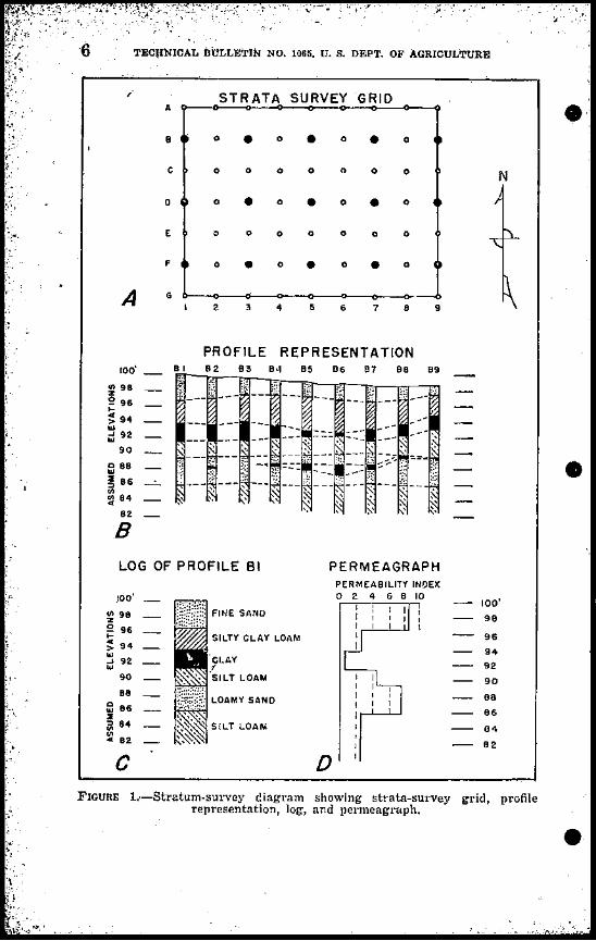
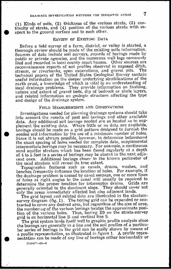

9
- ~
DRAINAGE lNVESTlGATlON METHODS FOR IHRlGATElD AREAS
bull a screw key which may be moved in and out of the slot by turning the adjusting handle This permits locking the handle at any point along the shaft Boring is started with the handle at a height of about 4 or 5 feet as the hole deepens the handle is raised on the shaft The depth of boring is indicated by marks on the shaft spaced at 1-foot intervals
Several power augers are in commercial production One type of portable digger folds into the bed of a pickup truck This machine has a 4-cycle 3-ho1sepowe1 gasoline motor mounted dilectly over a telescoping drill shaft which can be extended to 10 feet By coupling on additional shafts drilling can be still further extended to a maximum depth of 30 to 40 feet Optimum operating depths however are from 8 to 16 feet depending on the kind of soil mld the moisture conditions Drill bits range from 2 to 10 inches in diameter From four to six 10-foot holes per hour can be bored under average soil conditions Use of the portable type is limited to areas accessible to the light transportation equipment on vhic11 the device is mounted
bull
Boring with augers has several cliHadantages It is difficult to distinguish in the soil samples any thin Htrata of sand silt and clay that are 2 inches or less in thiclmess The Hamples themselves may become mixed with other soil as the auger is withdrawn Borshying is alHO Jikely to destroy the inherent soil Htructure andl11akes it difficult to identify minute soil lenses by visual inspection In saturated sand boring is mechanically difficult because material from the sides of the hole flows back into the hole andleplaces the removed soil almost as quickly as the sample is withdrawn
Jetting if8-The character of the subHoil at depths below 20 feet is important in connection with certain drainage problems especially where artesian pleSHUres may be a factor The jetting rig is probably the best type of device for logging sands and clays to depths of 20 to 100 feet (1011)3 It consists of a Hmall tube -inch to 1-inch in diameter which is forced vertically into the ground Vater is pumped into the tube under pressure The ease with which the tube passes through successive segments of the soil and the nature of the Hoil that bubbles out around the outside of the tube give a good indication of the location of sand Or clay in the profile The texture of the subsurface materials is also indishycated by the jetting pressure and rate of boring
Jetting may be difficult here caliche or other hardpans are presshyent Where extremely coarse gravels are encountered aqua-gel or drillers mud mUHt be used with the jetting water to enable the tube to penetrate the strata
Cming tubes-Neither the auger type of tool nor the jetting techniques are suitable fol obtaining soil samples intact-undisshyturbed samples-for analysis of physical and hydraulic characshyteristics and for other mmlyses h1 the laboratory For these purshyposes several inexpensive typefi of coring tubes are more suitable
rfhe Veihmeyer type of Hoil-Hnmpling tube can be used to obtain
bull cores of small diameter 111 an but extremely COinfie soils This tube ranges from 5 to 25 feet in length and con-ists of seamless steel
aUatie numbers in parenthescs Icfci to Lilclatt1lc Ciled
10 TECHNlCAL BULLETIN NO 1065 U S DEPT OF AGRICULlURE
bull
K
M bullo J--t--L
WOOD AUGER I 14 DIA FISH TAILED AND FLARED TO EXPEDITE BORING ONE SIDE OF THE AUGER CUTTING EDGE CAN BE COATED WITH HARD SURFACE ROO THIS HARD CUTTING EDGE SLOWS DOWN WEAR ON THE AUGER AND ALSO ACTS AS A SELF-SHARPENER
FIGURE 2-Imperial Valley soil auger
bull
DRAINAGE INVESTIGATION METHODS FOR IRRIGArED AREAS 11
tubing 1 inch in inside diameter fitted with a driving head and point The cutting point is made of case-hardened nickel steel and has a choke bore which permits the soil core to slide up inside the tube without serious friction The tubes are driven with a sliding hammel which fits over the top of the tube The usual practice is to drive in I-foot stages as indicated by I-foot graduations marked on the outer wall of the tube A special jack fitted with a set of grippers is used for pulling the tube however under ordinary conditions of soil moisture a jack is seldom l1eceSS~lY Figure 3 shows this tube together with driving hammer and extracting equipment
bull
FIGURE 3-Veihmeyer type of soil-sampling tube which has been driven into the soil The gLippers and jack are used to pull the tube out of the ground The hammer llsed to drive the tube is shown in foreground
Sampling by this method gives accurate plo(j)e logs since the relatively undisturbed cores clearly show the soil structure minute stratification contacts between strata and other physical soil characteristics The small diameter of the samples however preshycludes their use for laboratory tests of permeability based on unshydisturbed soil Other disadvantages of the method are the unsuitshyability of the tube for sampling strata that contain stones 01 large gravel the difficulty of securing cores below the water table and the difficulty of extracting moist sand or clay from the tubes
For sampling to depths that do not exceed 30 inches the coreshy
sampling apparatus originated at the Ohio Agricultural Experishyment Station and subsequently improved by Uhland (12) is availshyable In using this device it is necessary to dig a pit to secure sucshy
12 TECHNICAL BULLETIN NO 1065 U S DEPT OF AGRICULTURE
1
1(~
bull
FIGURE ltt-Field core-sampleI patts before assembly 1 and 2 driving assembly 3 and 6 upper and lower shoes respectively 4 extra cylindrical head for use in taking cores with jack 5 bale for pulling shoe assembly 7 aluminum cylinder fits into 3 8 shock ring fits on top of 7 0 pint carton for transporting cylinder and soil core
cessive depth samples FigurC lt1 illustrates the core sampler and its variolls parts and figure 5 its assembly for use in the field
The digging of pits for core sampling is obviated by the use of a modified core sample) (fig 6) When this sampler method is followed a cleaning tool is used to ream out the hole and shape the bottom after the hole has been dug to the desired depth with a postshyhole auger lhe (ore sampler is then inserted to the bottom of the bull
13 DRAINAGE INVESTIGATION METHODS FOR 1nRTGATED AREAS
hole and the shoe iH driven into the soil by the force of a sliding
bull hammer striking the top of the sampler shaft A similar device desi~ned to Hecure in-place samples at any depth
don to about 10 to 12 feet is the Pomona type of soil-sampling delce A post-hole au gel 01 orchard auger is used to open the hole to the depth desired and the sample iH then taken with the coring tube This method can be used only where the water table is below
bull
FIGURE 5-Core sampler heing assemhled lHCparutolY to taking sample3 x 3-inch aluminum eylindtgtl (c()ntcl) (its into shoe ussmnblYi base of driving assemhly (left) i~ inscltet in the upper end of the shoc l-llint container at right
the sampling leel The Ohio type t1w Uhland modification and the pomona coring devices ale so deHigned that the Hoil snnwlc may be left in the coring tube for transpoltation to the laboratory for analysis
bull
Other coring tubes have been developed for securing in-plRce cOJes of various t~rpes The Imperial Valley soil-sampling appa~ ratus (3) is designed to secure in-place Hal11ples beneath the sat~ urated zone of the soil A powel-driven machine desipnccl by the Utah Research Foundation and no in commercial production takes 4-hlCh cores lip to 10 feet in length in some typeH of soils rhis machine requires optimum soil-rnoiflture conditions to fl1nc~ tion properly In wet soils the core may HUck in the tube and clog the bit in soils that alC too dry the core may tend to crumble
14 TgCIINICAL IlUILWrIN NO 10ar U S DEll OF AGRICULTURE
bull
FIGURE 6-Modified sampler The bottom of the sampling hole is reamed out and shaped with the cleaning tool (4) The COIe sampler attached to the bull bottom 01 the sampler shaft (f) is then inserted to the bottom of the hole and the shoe of the sampler is driven into the soil by cllopping the hammer (shown in front of Rampler) on top of tlw sampler shaft C Sampler shaft handle with shock fitting and lowel (nel of Rlliking hammer
DEPTH OF DORINGS
In Roil-survey work the suiJsurfaceincstigations are generally confined to the upper 5-foot layer of soil in drainage investigashytions of irrigated lands it is necessary to know the character and the extent of the drainable strata to depths of at least 9 feet and frequently much deeper This is because the ground water in many irrigated aJeas contains haJmful amounts of Halt and the water table must be lowered to a depth of 4 to 5 feet to prevent injury to the roots of gJowing plants The water table must be kept low in order to control subsequent upward movement of salt Furthershymore for drainage lines to function properly for subsurface drainshyage they must generally be jnstalled at depths of 5h to 8 feet for tile lines and 6 to 12 feet for open drains Borings must therefore be deep enough to provide data adequate for design requirements
Watel moving thlollg-h the soil to a tile line open drain or other point of collection follows a cUlved path or streamline of flow (4 6 7 9) Figure 7 shows two typical patterllS of ground-water movement through the soil to a tile drain The flow pattern for pervious homogeneous soils normally curves below the tile level bull
bullbull
--J
DRAIN~GE INVESTIGATIQN METHODS FOR IRRIGATED AREAS 15
and back up to the tile whereas in stratified fine-textu~d soils the streamline flow may he sharply restricted Thus j the presence of lmiddotestrictive soil layers partly determines the spacing of tile lines and the optimum depth at which they should be placed Adequate information on the character of the deeper soil layers may obviate the error of locating tile lines in or below impervious strata Inf01middotshymation on soil strata to depths of 8 to 10 feet is essential for the design of tile systems to depths of 10 to 15 feet for open drains to depths of 15 to 25 feet for sumps and shallow wells and from 25 feet down to the proposed depth of the well for drainage byl11Eans of pump wells
In farm-drainage investigations it is well to keep in mind that
~ I bullmiddotl middotmiddotrmiddot middot I bull r~middotw ~bullbull ~rmiddotmiddot jyOn middotmiddot-middot1middot I I 1 I I 1 I I I 1 I I I I I I I I I I I I I I I I I I I I I I I I I I I I I I I I I I I I I I I I I 11 I A I 1 1 Iii II i I I I I I I I I
I I I I I -- ---~~~9f~~~- __ ---~Q~~lt-_ ~~~bullbullbull~ loi ~~)t~~(~ bull bullbull m IIIn ~H bullbullbull ho
bull HIINItIIW IOtINt iVtHtIHIIlUVtJIIIIf
kotmiddotmiddotmiddotuII middotI~IIIlIII 111 IIUII N~ 11 itt IIIII ~ lto rt
I1ImiddotUlIIn If v 11 I f bull bull bullbullbull vbullbull f
ulllI HltoH bullbull hrU II 10 bullbullUI OUII ~nmiddotIHn ntl
ImiddotIIIIVII h IMPERVIOUS CLAY STRATUM middotIIHIII oJ H~ UlOII i IHuU iI II t fj IHI I
bull~I H Ih bullbull 1 Iull IJ 11bullbull11 H If II ~ lu bullbullVIi U II ~
bull If~ J 1 10 vt1 1 011 bullbull u bullbullbulli If 1 bullbull j
11 h~ ffHI nlll U V(jf It~ bullbullbull 1 iI to ~ bullbull bullbullbullH
FIGURE 7-Lines of flow to a series of drain tiles A In an aquifer overlying an impervious clay stratum n in an aquifet~ without an impervious clay stratum or other harder
213H7D-53-3
middot
16 rECHNICAL BULLETIN NO 1065 U 8 DEPT OF AGRICULTURE
one 12-foot hole is better than two 6-foot holes and at least one 9shyfoot hole should be bored on each 10 acres
RECORDING BORING DATA
A log should be made of each hole bored preferably at the time the boring is made At the same time the location of the hole should be marked on the map of the area as an aid in delineating the boundaries of different types of drainable or undrainable soils
Survey notes which should be made as the boring progresses should include information on the depth to water table the relative moisture content of the various strata the degree of staining or discoloration of the soil particles and the )resence of roots and minerals Where core tubes are used notes should be made of the soil structure minute stratification and the presence of lenticules Or sand-filled cracks that help to improve permeability in the clay parts of the soil profile and if the boring is in sand strata of minute layers of silts or clays that tend to slow up the movement of water
The identifying characteristics of a giYen soil once determined can often be used to classify and delineate similar strata elsewtere For example the minute shells typical of the best sand aquifer material in one part of a large irrigated valley usually serve as a good indicator of favorable drainage properties in the sand strata of other parts of the same valley Thtls certain strata of soils can sometimes be traced over an entire drainage area
Identifying soil characteristics helps to maintain a high degree of consistency in subsoil mapping in which several technicians take part and tends to reduce day-to-day variations in accuracy of observation by the same individual These soil characteristics may also be used to roughly gage in the field the relative permeability of the various soil layers as an aid in preparing the permeagraph previously mentioned
A convenient method of plotting the logs of a series of borings is to draw a profile delineation of the underground strata Such a chart helps in determining the relation of the dip and slope of the clay and sand layeni to the slope of the ground surface to the varishyous topographic features and to the slope of the water table
The position of the water table in relation to the soil strata as determinfd from the borings is readily seen when the vater table js plotted on the profile-delineation chart The exact series of profiles to be used in the charting depends on the nature of the drainage problem In mountain alleys it is essential to draw several delineations down slope in order to locate accurately the underground extension of water-bearing aquifers that crop out to the surface Where tile systems are planned a profile delineation should be drawn along the general alinement of each tile line
A method of depicting the boring data for mountain areas is to locate the several boring sites on a hUge-scale map of the problem area and insert a small-scale columnar chart of the log at each boring site shown on the map Distinctive eolotmiddots or other markings are used to show the thickness of the respective strata A study of
bull
bull
bull
DRA1NAGE lNVESTlGAT10N METHODS FOR lRRlGATED AREAS 17
the map and related data will reveal the optimum location for drains
Important layers of heavy clays or coarse~textUled sands that are continuous over large areas may be plotted to advantage 011 a subsurface contour map For example a continuous stratum of fine-textured clay may underlie a coarser drainable soil at depths varying from 4 to 8 feet below the surface Plotting the upper surshyface of the clay layer on a contour map locates the low valleys of the relatively impervious layer Such information facilitates the planning of a drainage system that will drain all the area with a minimum footage of drains
SOIL-PERMEABILJTY DETERMINATIONS An estimate of the permeability of the strata underlying the soH
surface is essential in developing sound techniques of land dlfin age Water-transmission rates should be determined in quantita~ tive terms to be of practical use in this connection
COEFFICIENT OF PERMEABILITY Coefficient of permeability may be defined as the rate of flow of
water through a unit crolgts-sectional area uuder a unit head during a unit period of time For convenience in making comparisons coshyefficient values are stated in terms of flows of water throughsaturated soil
Methods of accurately determining the coefficient of permeshyability may be grouped in three broad classes as follows
bull 1 Field measurements (a) Direct measurement of the permeability of an entire
soil profile based on pumped~well data A drawshydown curve and data on quantity of water pumped are used to compute the coefficient (13)
(b) Direct measurement of the permeability of indishyvidual strata by means of small tubes piezometers 01 auger holes (5)
2 Laboratory measurements utilizing a permeameter device and either in~pla(e undisturbed specimens taken in the field by means of one of the various sampling devices or samples of dilgtturbed soil prepared for laboratory examina~ tion by dryi)lg the soil and packing it into the permeashymeter
3 Indirect evaluations of permeability based on physical and chemical soil properties
Each of these methods has its merits and draw-backs The par~ ticular method selected will depend upon the requirements of the drainage survey the availability of appropriate measuring devices and the degree of accuracy desired
FIELD MEASUREMENTS OF PERMEABILITY-The determination of subsoil permeability by means of direct field measurements makes use of formulas based on the flow of water through the soil to a discharging well A basic assumption of these formulas is
bullthat the cone of depression representing the pumped water table around the discharging well is in equilibrium ie the discharge
t
i
bullbull
(i
TECHNICALmiddot BULLETIN NO 1065 U S DEPT OF AGRICULTURE
r~semt1on ells
StaticJUlr _ I-- -- - f--r - -- 1----1 - shyfable
5 ~ _- _ 40---+--_shy____ -=ifshyr---
pgp1~ ter fable V
h
I ~
Aquiler bull
FIGURE S-Diagram of factors involved in calculation of permeability coshyefficient from field measurements with well extending thrQugh aquifer to barrier stratum
from the well balances the inflow from the water-bearing stratum To secure the field data a stratum survey is made of the proposed well site a small well is put down to tap the aquifier and a system of observation wells is laid out around this well The well is then pumped until equilibrium is reached between the discharge and the drawdown around the well
The measurements needed to evaluate the permeability coefficient are the quantity of water (Q) obtained by measuring the well disshycharge the hydraulic gradient (I) as determined by the position bull
19 Q-
DRAINAGE iNVESTIGATION METHODS FOR mRiGATED AREAS
of the draw-down curve for the observation wells and the area of fio (4) as determined by borings The coefficient of permeability (P)is calculated using an adaptation of the Darcy formula
In simplifieurod form the adapted Darcy formula is Q = PIA Assuming that the well extends through the aquifer to the barrier stratum the formula is expanded to
Q 1og IfR2
P= __~__~~~~1~-=~ 1f (h2 + hI) (S1 - S2)
The dimensionless factors entering into the solution of this formula are shown in figure 8
The soil water table and other hydro)ogic conditions under which this formula may be used have been stated by Wenzel (13) as follows
A water-bearing bed of uniform permeability is assumed to rest on a relatively impervious formation of indefinite areal extent A well equipshyped with a pump extends to the bottom of the water-bearing material and two observation wells are placed on a line with the pumped well The pump is operated at a uniform rate during a period in which the water table declines and takes a form similar to an inverted cone around the pumped well The nonpumping water table and the underlying impershyvious bed are assumed to be horizontal
Various modifications of the basic Darcy formula of flow of water through soil are used depending on the site conditions and the measuring techniques employed Modifications are necessary for example for flows from confined aquifers or from aquifers under artesian pressure The use of this method must be varied also lor aquirels which are not uniformly permeable horizontally and vertically And in any event of course its use is limited to areas in which the water table is high enough for practical pumping
The mathematical explanation of the derivation of the various formulas applicable to specific field conditions including the derivashytion of the formula mentioned above is fully described by Wenzel al1d other workers in the field of hydrology and will not be Ret forth in detail here
In another type of field measurement water is introduced through a pipe or well of small diameter that taps the soil stratum to be investigated 311d the rate of flow is measured A variation of this technique is to pump the water out of the tube and time the rate of leCOvely in the tube Frevert and Kirkham (5) described a method for measuring the permeability of the soil below a water table
Although they probably provide the most accurate permeability coefficients field measurements are relatively time-consuming Furthermore the field sites for the measurements must be carefully selected LABORATORY MEASUREMENTS OF PERMEABILITY~Laboratorymeasshyurements likewise are highly accurate when in-place samples are used but they too require much time and in addition considerable
bull special equipment They may be made either by the use of in-place undisturbed cores taken in the field and brought to the laboratory
20 TECHNICAL BULLETIN NO 1065 U S DEPT OF AGRICULTURE
for tests or wifh samples of disturbed soil that have been dried reshyduced to granule size and then packed into a permeameter tube for testing Both methods require special tools and equipnlent and rigid conformance with standard procedural techniques as described by 1fuskat (9) and other workers In solving drainage problems of a difficult nature and those in which high values are at stake the use of the more time-consuming complicated and expensive laboratoryinvestigations usually is justified Fallin Head Pelmewmete1-The falling head permeam~ter is an instrument suitable for use in the field or in a field office laboratory to obtain quick and reasonably accurate measurements of permeshyability A permearneter of this type patterned after a similar device used by the United States Geological Survey (13) was developed for use in Imperial Valley Calif4 lhe device consists of a soil column and a water column connected by a L-tube and of measuring and other attachments Water is introduced into the water column From there it flows through the U-tube into and through the soil at a iowel elevation in the other columlL The rate of flow is a measure of the permeability of the soil
The Model-A type (figs 9 A and 10 A) consists of a 2-inch brass soil cylinder connected at the base with a small copper U-shaped tube to which is attached a glass manometer tube An auxiliary water-supply cylinder is connected to the U-shaped tube to furnish water for the tests Water is allowed to pass from the supply tube to the soil tube until it saturates the sample and begins to flow over the top rim of the brass cylinder The supply valye is then turned off and the rate of the drop of the water in the graduated glass tubes is noted This rate of drop is an indication of the permeabilshyity of the soil
The Model-B type (figs 9 B and 10 B) is constructed of materials that are readily available in most localities The soil cylinder is made from a short length of 11-inch smoothly reamed pipe This is threaded to a 114-inch coupling which in turn is attached to a series of reducers nipples elbows and other fittings This device is relatively inexpensive costing approximately two dollars for the material The fittings may be obtained in any plumbers shop and can be assembled with a pipe wrench and soldering iron A coating of stopcock grease is applied to the threads on the end of the soil tube to prevent leakage
Figure 9 shows details of construction and gives the dimensions and material lists for permeametel types A and B respectively Figure 10 illustrates the assembled permeameters and parts
The soil tubes of both models being demountable from the rest of the device can be used to obtain undisturbed soil cores for testshying purposes without dismantling the entire apparatus or taking it to the sampling site
In-place samples are obtained by pressing the sampling tube into the soil with a hydraulic j~ck Side friction and resultant compresshysion of the soil sample can be greatly reduced by wetting the soil
of Bradshaw G B and Donnan T W A Falling Head Permeameter for E-aluating Permeability U S Dept of Agric Soil Conserv Service 1950 (Processed)
bull
bull
bull
bull bull ~~~c
~~
o 0 0 0 0middotmiddot8 o 0 0 1 ~ ---Y
9
~~~Ddeg o 0
~5middotbull L ~A ampCHID) ) bull middot amp r~ ~~ rw HOI[ Jln ~ 1~~1
Tz_rti~v ~r SUfO ZU)it VI
middot ~ L
Ilbull bull ~
middotbull
B
---L ~
0I I I ~_LI
1 ___ ___ J
QO
-
t1 liS gt ~ sect
i r 111amp-shy
~ LI~~middot~a L
i bull ~111t-t1rOOfT~
114100
~1J~~~l 11 n_
01 cWtllI
cl i
gt ~ ll( tl
~ ~s
~
FIGURE 9-Construction details and materials specifications for falling head pellneameter A Type ~ A S type B ~
~
~tgt V C bull -~~ ~~
22 TECHNICAL BULLETIN NO 10G5 U S DEPT OF AGRICULTURE
tube prior to sampling Vertical samples can be obtained by using
the car bumper as a backstop for the jack In order to obtain horishyzontal samples it is necessary to dig a sampling pit and push the sampling tube into the side of the pit with the jack using the bullopposite wall of the pit for leverage Veltical samples can be taken to depths of 8 to 9 feet with the Model-B sampler by first boring a hole with a post-hole auger and then using a 1 Y2-inch pipe-extenshysion handle on the permeametel soil tube
In both shallow and deep sampling the samples should be careshyfully removed from the surrounding soil and the extruding soil gently broken away The ends of the samples are then trimmed
bull
FIGURE lO-Two types of perl11eametcls A Type-A permeamctel and parts 1 Assembled insttument 2 dismantled permeameter 3 cap used for jacking soil tube 9 into Roil 4 cap scrcws 5 ring to hold soil tubcin Jllace 6 scrcen and filter 7 cutting cdge for in-placc sampling 8 scating and rcaming tool 9 soil tube fl Asscmbled type-B pcrmeamctcl
with a spatula or other tool a paper filter is placed over the bottom end of the sample next to the soil and this in turn is covered by a screen to keep the soil from sloughing away The tube containing the sample is afTixed to the permeameter and the connections are tightened to prevent leakage A small weep hole at the point where the screen and filter join the soil sample is used to bleed the ail from under the soil sample and prevents ail from being forced through the sample As soon as the soil column is saturated the sample is bull
DRAJNGE INVESTIGATION METHODS FOR IRRIGATED AREAS 23 ~
ready to be tested Satisfactory results are obtained by using irri~ gation water for the permeability test
The size of the glass manometer tube to be used depends on the permeability of the soil to be tested For freely permeable soil a tube with a diameter of l15 55 01 75 millimeters is most suitable For slowly permeable soils a smaller tube of 1 2 or 3 millimeters should be used The device is so constructed that these glass tubes are interchangeable
The permeability of the soil sample is obtained by noting the time required for the watelin the glass manometer tube to fall from an initial head reading to some other desired head reading Computations are simplified if the initial head is set at 115 centi~ meters and the final head 5 centimeters resulting in a head difshyferential of 10 centimeters In testing slowly permeable fine-texshytured soils an ordinary watch with a second hand may be used for timing for more permeable soils a stop watch is needed
The coefficient of permeability is calculated by means of the following equation
d L hP =23025J - log _-_lt (3-600)D~ t 10 h
in which
bull p is the coefrkient of pelmeability in cubic centimeters pel
square centimeter pel hour d is the diameter of the glass tube in centimeters D is the diameter of the soil tube in centimeters L is the length of the soil tube in centimeters t is the time of fall of water f1ol11 110 to h in seconds to is the initial head in centimeters h ii the final head in centimeters and 3600 ii the factor for cOlwerting the result in second-units lo
hour-units Obviollsly fOl any given type of falling-head device many of these factors are constants TemlJ81aiw( cOlleclioll-The coefficient of permeability is defined for a water temperature of GOdeg F If the test is made with watel of ~lny other temperature the calculated coefficient must be corrected for the difference in Yiscosity of liquid due to higher or lower temshyperature lhis correction is necessary because the viscosity becomes less as the temperature rises and the rate of flow of water through the soil increases Viscosity is inversely propoltional to both temshyperature and permeability For each degree of temperature variashytion above 01 below GOdeg F the correction is made by multiplying the unadjusted calculated coefficient by the proper correction factor
The temperature-correction factors for converting coefficients of permeability computed at water temperatures of 40deg ot 90deg F to
bull coefficients of permeability at water temperature of 60deg F are given in the following tabulation
J
1 I
TECHNICAL BULLETIN NO lOGo Ubull S DEPT OF AGRICULTURE24 ~
of C011()ction of CltnIecfion of C011ection factm factor factor
40 137 57 ___ ___ _ 104 74 083 11 135 58 _ _ _ 103 75 82 42 133 59 _ _ ____ 101 76 81 43 131 60 ___ 100 77 80 44 128 61 ___ ____ 99 78 79 45 126 62 _ ____ 97 79 78
63 _________ 9646 124 80 77 47 122 64 ______ 95 81 76
~ T 48 120 65 _ _ _ _ 93 82 75 49 118 66 ___ 92 83 74 50 116 67 91 84 73 51 115 68 89 85 72 5~ 113 69 _ _ _ 88 86 71 53 111 70 _ __ 87 87 70 54 109 71 ___ 86 88 69 55 108 72 __ 85 89 68 56 106 73 84 90 _ _ 67
Results of tests-The most reliable and consistent measurements of the permeability coefficient h~e been obtained by the use of unshydisturbed soil samples taken ill place Laboratory-packed samples are less suitable since the same degree of compaction is difficult to obtain in aU samples Comparative test runs with in-place and packed samples reveal that for sand there is a fair correlation but for fine-textured soils the difference in results may vary as much as 500 percent
In using the in-place technique it is desirable to use both horishy bull zontal and vertical samples The flow of water horizontally through the soil under some conditions may be much greater than the flow vertically This is due to the tendency of certain soil particles in settling out of a suspension to fall with the flatter sides overlapshyping each other resulting in a shingle-like arrangement of the soil particles in the deposited stratum The bedding of soil particles in microscopic horizontal strata tends to impede vertical flow and thus t~nds to give higher coefficients for in-place samples taken in a horizontal direction This tendency is important because in actual practice drainage design is based mainly on flows to tile lines or open drains in a horizontal 01 nearly horizontal direction
For practical dr1inage-investigation purposes short-term test runs of about 1 hour on saturated undisturbed samples give a sufshyficiently accurate indication of the coefficient of permeability Alshythough many research workers feel that the only true test of flow of water through the soil requires a run of several days a comshypilation of permeability data for 26 different in-place samples of soil from Imperial Valley Calif showed that long runs were not essential for reasonably accurate determinations (table 1) The samples were taken in horizontal vertical and diagonal directions These runs were carried on for periods ranging from 96 hours to 906 hours Yet in a majority of the tests the measured coefficients of permeability at the start of the runs were only slightly different bull
~ laquo ~l ~~ -gt ~ ~
25
bull
bull
yen
I
DJiAINAGE INVESTIGArIOJ~ lttETHObs FOR IllRlGATED AREAS
from the actual average coefficient based on all the observations during the lmiddotUll
TABLE 1- Results of meaimIements of coefficient of pelmeability of soils) l1nperial Valle1l1 Calif1
CI Coefficient of permeability inUl TotalotDSample QJ5 houls cubit centimetetmiddots pel square eentimetpl pel hour
gt=~No ~s4-5 Tun Start of run End of run Average3 P-4~
of
I I 46-C1 H 214 1865 1472 1700 46-E2_ V 18r 313 524 478 46-E3_ H 188 710 1140 1085 46-D1 V 165 1100 1150 1112
Ul
46-D2__ H 120 1159 755 855 96-A H 284 115 157 137 96-A2 V 281 62 230 131 96-E H 284 73 168 123 122-A H 310 1408 1405 1395 122-B V 96 789 868 842 122-G V 906 1]75 750 914 123-A_ H 117 1115 1605 1150 123-Bbull H 116 1205 1105 1185 123-B H 342 1380 1044 1215 123-C_ _ V 146 867 1149 943 123-G V 169 868 652 736 125-A H 162 1370 14l5 1422 125-B V 841 885 714 865 149-A V 340 1090 7l1 1013 149-B H 362 778 840 809 149-C D 339 1130 1340 1151 150-A H 303 1810 2180 2241 150-B V 339 764 645 823 213-A H 483 77 56 71 213-B H 146 145 173 147 213-C V 479 106 75 103
1 Data from Preliminary Progress Report of Cooperative Investigations in Imperial Valley Calif 1943-44 by W W Fox V S Aronovici and W W Donnan Soil Conselv Service 1944 (Unpublished)
2 H-holhontal V-vertical D-qiagonal 3 Average based on all observations taken during the test
INDIRECT EVALUATIONS OF PERMEABJLITY-Some of the soil charshyacteristics that control the movement of vater through the soil are type of structure arrangement of aggregates grain size texture pore space dispersion swelling and type of clay mineral In many sections of the country including western United States visible soil characteristics have been correlated with measured percolation rates and the soil permeability is graded in accordance with a classification which has been used extensively by the Soil Conservashy
bull tion Service in describing mapping units of soil conservation surshyveys This classification follows
26 EEClINICALDULUJjJN NO 10M U S DEI OF AGJUCUIfjURE
larcolatioi r([il in i-chen Jmrmiddot hour Permctlbillty trouf satltrllted i8ltTHld corCB
Permeability clas8 illdo dcr IC hea of 10Mcr
Very slow _____ 1 Less than 005 Slow _ ______ 2 005 to 02 Moderately slow ____ 3 02 to 08 bullModerate __bull____ 4 08 to 25 Moderately rapid ____ 5 25 to 50 Rapid __ _ bullbull___bull 6 50 to 100 Very rapid _____bull 7 More than 100
t Estimating the permeability of significant soil zones below the topsoil by correlation with visible soil characteristics provides a means of delineating the general boundaries between drainable and undrainable strata The approximate ratings must be supplemented by actual field measurement~ however jf precise quantitative values of permeability are required Indirect evaluations such as these by which permeability is graded according to distinctive and
J easily observable soil characteristics are suitable only when sufshyficient correlations have been made between soil characteristics and water transmission rates in a particular locality to furnish a reshyliable base for the permeability estimates
WATER-TABLE INVESTIGATIONS
The water-table survey provides essential information on the position of the water table at different points in the problem area and in the various soil strata and on the extent and degree of severity of the drainage problem in general Ground-water flow patterns are prepared from the piezometric data obtained These flow patterns fUll1ish a good basis for the design of improvement bullworks
EXISTING DATA
Records of water levels maps of depths to water table and other hydrologic data for past years are available for many drainage problem areas Such data when correlated with current conditions often furnish clues to the cause of fluctuations in the water table The plotting of water-table hydrographs in conjunction with data on precipitation irrigation runoff effect of pumping and other hydrologic phenomena provides a useful basis of analYRiR
OBSERVATION WELLS
Unfavorable water-table conditions are often indicated by cershytain well-recognized symptoms Thus poor crop production and the presence of marshy areas or alkali spots usually are visible evidence of waterlogging The use of observation wells however is necesshysary to obtain positive data on the position and fluctuation of the water table
The type location and number of observation wells to be inshystalled depends on the type of informatiol1 needed The most comshy1110n types are open holes bored with a soil auger 01 post-hole auger or wells drilled with a commercial rig Open holes made in the course of soil surveying can also be used for this purpose Open bull
bullbull
middot
bull
DRAI~AGE Il-lVESTIGArwN MElHODS FOR IRRlGNlED AUEAS 27
wells if they are to be used for any length of time should be cased to prevent caving Casing materials range from thin sheet-metal pipe stovepipe and drain tile to the standard commercial types of well casing
The kind size and depth of well and the type of casing depend largely on the type of investigation being made For a reconnaisshysance of a small plot of ground auger holes usuaily suffice for a valley-wide drainage investigation observation wells of a semishypermanent type should be installed The mot effective system for a valley-wide investigation is a series of wells in a grid pattern oriented to the strata-survey grid to facilitate correlation with soils data
Observation wells are generally installed by placing the pipe or casing in an auger hole dug to the desired depth as shown in diashygram A of figure 11 Casing pipes range from inch to 6 inches in diameter Pipes open only at the ends should be set on a small quantity of gravel at the bottom of the hole Gravel is then backshyfilled around the pipe to a point above the ground-water table Native material may be used to fill the remaining portion of the hole to the ground surface The pipe is left projecting 12 to 18 inches above th( ground surface and is covered by a pipe cap to protect the well
PIEZOMETERS
A most useful drainage-investigation tool is the ground-waterpiezometer an unperforated small-diameter pipe so designed and installed that after it has been driven into the soil the underground water can enter it only at the bottom end (12) The device regisshyters the hydrostatic pressure of the underground water only at the bottom of the pipe Almost all types of cased wells on the other hand are perforated throughout their length or have numerous access points for water to pass from the soil to the well In an open uncased hole 01 ordinary cased wall therefore water seeps in at all points and fills the hole to whatever height the strongest hydroshystatic pressure will produce Such a well registels the depth of water or hydrostatic pressure in the entire soil profile penetrated by the well Diagram B of figure 11 illustrates this fundamental difshyference between the piezometer and an ordinary well
The availability of an instrument like the piezometer which can be used to ascertain the hydrostatic pressure at any level in the soil profile opens up a wide range of possibilities in drainage investigashytions Since underground water moves from a point of high hydroshystatic pressure to one of low pressure the movement of water can be charted if the hydrostatic pressures are measured With sets of piezometers spaced at intervals the hydrostatic pressure at difshyferent points in an entire profile may be determined and seepage movement detected Under certain conditions a single piezometer may be used to reveal seepage as when a piezometer pipe is inshystalled in the soil in the center of a flowing canal or drain If the water level in such a piezometer is higher than that in the canal it may be an indication that water is seeping from the lower level soil into the canal
0
OBSERVATION WELL PIEZOMETER WELL DRIVING HAMMER
r- r- ~tQ PIEZOMETERGROUND -tilSURFACE oGROUND SURFACE~ -1 = ~ Z
~~ t ~~ PIPE ci
I I c t_~UND_ _~~E -1__L -~EL t
~--~l- -11111 =tII
Z III
~sectl --+ I III - z ~I 1I11I
e -)--
shy
i -1111 -III ~-111- CA POST B iL PLUG
HOLE til III
rnJ -c- CAVITY FORMED dARROWS INDICATe BY FLUSHING ~It
~
GROUND WATER ENTRANCE -II) LI 34 PIPE
1 THE PIEZOMETER INDICATES THE PRESSURE AT THE POINT OF ENTRANCE RATHER THAN C)LrY o
gt THE LEVEL OF THE GROUND-WATER TABLE
g ~
GRAVEL BACKFILL ALLOWS ENTRANCE THE WELL INDICATES THE LEVEL OF THE OF WATER FROM ANY POINT SURROUNDING GROUND- WATER TABLE
~ ~
~
FIGURE ll-Some details of observation wells and piezometers A Cross-section view of observation well showing proper method of backfill B diagram illustrating fundamental difference in flow of underground water to well and piezometer C detaifs of piezometer driving hammer and method of installation (from Ground-Water Studies in Relation to Drainage by J E Christiansen)
-
_
-j-ibullbull bull bull
29
bull
e
DItAINAGE INVESTIGATION METHODS FOIt IfHUGATED AREAS
DESCRIPTION OF PIEZOMETER The ground-water piezometer consists of a standard 14- or shy
inch iron pipe driven vertically into the ground to a definite level Before driving is started a loose rivet is placed in the lower end of the pipe to keep soil from entering When the desired depth is reached a jointed rod is inserted and the rivet is punched out leaving an open pipe or piezometer In some soils the prptecting rivet is not needed Before driving the exact length of the pipe should be noted so that the elevation of the bottom of the pipe after driving may be determined
The driving is done with a special hammer fashioned like a steel fence-post driver It consists of two pieces of -inch pipe 15 inches and 5 feet long respectively joined by a 1-foot section of 1 lh-inch pipe filled with lead (diagram C of figure 11) This leaded section is fitted with a steel plug at each end to receiye the impact of the blow The top of the piezometer pipe is fitted with a removable -inch driving head The piezometer is started into the ground with the 5-foot end of the hammer over the driving head of the piezometer When the top of the piezometer has been driven to within 5 feet of the ground surface the hammer is inverted and the drivil1g continued until the top of the piezometer is at the desired elevation about 1 foot above the ground Piezometers may be driven with a pneumatic jackhammer if the top of the piezometer pipe is fitted with a driving cap for seating the jackhammer pilot Power driving makes it possible to install piezometers to a depth of 30 feet even in very heavy soils Figure 12 A shows a piezometer being driven with a jackhammer
The deeper the piezometer penetrates the soil the greater will be the friction on the sides Since hand driving of even a 15-foot piezoshymeter in some soils may entail considerable laber the use of this method is definitely limited Placing a joint and coupling about 1 foot from the bottom of the pipe slightly enlarges the hole through which the pipe passes as the piezometer is forced down This helps to reduce side friction and cuts down the resistance to penetration The use of such a coupling permits driving of piezometers by air hammer to depths of approximately 40 feet without causing leakshyage down the sides of the pipe and a resultant los~ of benefit from the piezometric principle Earth from the side walls of the hole closes up the enlarged space surrounding the pipe above thE coupling The 1-foot section of pipe below the coupling is of course ealed at all times against any leakage
Piezometers should be driven as nearly plumb as possible Single lengths up to 14 feet may be installed by working from a stepshyladder For greater depths several sections of pipe are joined with standard pipe couplings the maximum depth of installation being limited only by the difficulty of driving the pipe and removing the rivets
FLUSHING For sllccessful installation and operation of piezometers the
soil at the lower end of the piezometer should be removed by flushshying leaving a small cavity at the bottom of the pipe as shown in diagram C figure 11 Flushing is done by punching the rivet from
bull bull bull
o
tl o z Qgtshyrshycc t t
~ Z z ~
~ S c tl ~ o
gtshyCi ~
(=jc
~ C
FIGURE 12-Driving and jetting piezometers A Driving 14-inch piezometer with an air hammer Tubing in lO-foot lengths may be joined and sunk to a depth of 30 fect by this method fl Jetting] 2-inch piezometcr Coachella Vallc~r Calif
lt
j
bull
gt
J)RAINAGE INVESTIGAflON METHODS FOR IIUUGAtEIgt AUEAS 31
the lower end of the piezometer by punch rods after the pipe has been driven to the desired depth then cleaning out the pipe by pumping water into it through a flexible tube The water escapes by flowing upward through the narrow space between the tubing and the inside wall of the pipe The equipment needed includes a water container stirrup pump and enough plastic tubing l4-inch in outside diameter to reach the bottom of the deepest piezometer used (fig 13) The tubing is marked with colored lacquer at I-foot intervals
rmiddotbull
~
r
~ I
FIGURE 13-Some equipment used in piezometer and well investigationsLeft to 1iuht StilTup pump and plastic tubing for flushing electric watershylevel indicator for piezometer sounding bell for 1-12-inch and larger pipes sounding rods usable also as punch rods for lemoving rivet from piezometer
The plastic tUbing is pushed down inside the pipe during pumpshying until it nears the bottom then gradually lowered until the end is about even with or slightly belOW the end of the piezometer~ Flushing is accelerated by working the tubing up and down care being taken to avoid lowering the tubing beyond the depth specified The water that overflows the pipe is usually very silty at first With continued pumping however the water clears The tubing is then slowly withdrawn while pumping continues
TECHNICAL BULLETIN NO 1065 U S DEPT OF AGRICULTURE
The piezometer is tested for sensitivity by filling the piezometer I~ pipe and observing the rate at which the water drops Experience
will soon indicate the approximate rate to be expected If the rate of drop appears too slow the flushing is repeated the tubing being bulllowered slightly below its previous level to enlarge the cavity In l1ighly permeable sands piezometers take the water so rapidly that no overflow occurs whereas in some soils of low permeability the rate of subsidence of water in the piezometer is hardly perceptible In some instances an equilibrium level is obtained in a few minutes in extreme cases 24 hours or more may be required
In some soils piezameters may be driven to advantage without rivets Although plugs of soil 6 to 8 inches long may pack in the lower end they can be flushed out in less time than would be reshyquired to punch out the rivets
Piezometers may occasionally seal up after being in use for several months Erratic variation in the pressure reading of any piezometer as compared with others in the same vicinity may indishycate sealing which can be readily overcome by reflushing
JETTING PIEZOMETERS
Both piezometers and wells have been installed successfully in certain areas to depths of 100 feet 01 more by jetting (10 11) Figure 12 B illustrates jetting- equipment designed and built for use in connection with cooperatie drainage investigations in Coachella Valley Calif Much greater depths can be attained by jetting than by driving the depth of installation being limited mainly by the size of the aggregate encountered Some highly bull porous formations take the water faster than it can be pumped down and 110 deepening of the jetted hole results
In jetting the soil is removed by flushing it up around the pipe and out of the hole Although this may result in side leakage and cause the pipe to act as a regular well when the well is new the sides seal up after a period of time and the well then functions like a piezometer The difficulty of determining the extent of the seal along the sides of the pipe makes it hard to determine whether the readings obtained are from a well or a piezometer Nevertheless jetting is a quick and easy way to install a deep observation well and the ease and economy of installation far outweigh the limitashytions
REMOVAL OF PIEZOMETERS
Piezometer pipes may be used many times over if care is taken in removing them from the ground Lengths up to 8 feet usually can be pulled by hand after they have been loosened by turning with a pipe wrench For deeper installations the pipes are easily exshytracted by means of a ratchet hoist suspended frol11 an A-frame or tripod of 2- by 4-inch material (fig 1lt1) A set of small metal grippers is fastened to the piezometer and attached to the pull chain of the hoist After removal the pipe should be cleaned of soil and corrosive scale straightened and if non galvanized covered with a light coating of oil to prevent rllsting
The piezometer tube may also be raised with an ordinary soilshy bull
33 DRAINAGE INVESTIGAT()N METHODS FOR JHRiCAlEIJ IEAS
bull
bull
FlGCRf 14-Ratcl1lt hoit tlipod and glippC) used in (gtxtracting d((p pi(Z(lIl1lttI pjPt~
tube jack using a S(lt of sl1lalll1lltal grippers fittcd around the pieshyzometer pipe to provide a btHling sUJfaec fol the jade
MEAseRIXG DE1(ES
There are lJlany differcnt methods of measuring the water elenltion in OIJiienution wells and pieometcls For 11 ~-inch and laJger pipes a sounding b(1 (lig ]3) can be utilized The bell is made by boring out th ((nLer of a l-ineh-c1ial11etel brass rod to a depth of 1 inch until the walls aJe approximMely 1 i32-inch thick A I~-inch shank is formed by turning clown the end of the rod for about l ~ inehes and ~pttilJg a Jin in the end A brass chain about 0inChes 10llg is used to join t11( b(11 to the low-reading end 0pound a metalli( tape Ir it lulJ-lengtJl Lapp is used without foreshortening a correction must )( applied to the watcl-t(ation reading- to COIll shy
bull l1ensate 101 the 1ltIlgth of the sOLinding 1)(11 and ehain As an alternashy
~~
TECHNICAL BULLETIN NO 1066 U S DEPT OF AGRICULTURE34
tive a piece of the tape equal in length to the combined length of bell and chain may be cut off before it is fastened to the chain The tape then gives direct readings The bell is lowered on the end of the tape until the sound of the bell which is clearly audible as much bull as 100 feet from some wells indicates that it has contacted the water surface
A relatively simple adaptation of the sounding bell described above designed to facilitate the reading of open uncased holes made with soil augers has been used successfully in wells of small diameter The bell of this device is made by brazing a large cartshylidge case similar to a 45-70 to a jointed 1b-inch rod The rod is graduated and marked as desired
The depth to water in piezometers and wells may also be sounded by lowering a length of plastic tubing into the pipe while air is being blown into the free end of the tUbing above grutdd When the tubing touches the water an audible vibration is set up in the pipe The water level may be determined either by withdrawing the tubing and measuring the length removed or by using a tube on which unit distances have previously been marked with differently colored lacquers
WATER-LEVEL INDICATOR FOR PIEZOMETERS
The type of sounding device commonly used for larger observashytion wells is unsuited for use with piezometer pipes of small diameter A satisfactory electric water-level indicator has been developed for this purpose (fig 15) The essential parts of the deshyvice are a flexible rubber-covered wire marked with I-foot gradua- bull tions small penlight batteries for current and a milliammeter 01 voltmeter to indicate the closing of the electric circuit
The wire should be highly flexible well insulated and not easily kinked Type FF single-conductor flexible cord is satisfactory
The end of the wire is equipped with a weighted sounder tip made from about eight lengths ofYi-inch brass tubing each section 11 inches long This flexible end permits the plumbing of bent and damaged piezometers The insulated contact wire passes through the series of tubes and is soldered to a metal tip This tip is inshysulated from the brass tubing with a piece of lucite machined to fit into the end of the tubing The wire is marked at I-foot intervals with bands of colored lacquer to indicate successive foot readings It is held on a reel and passes in front of a fixed scale 1 foot long graduated in tenths and hundredths of a foot This scale reads from the top down so that readings are obtained directly to 001 foot A reel harrow enough to accommodate only one width of wire has been found most satisfactory
A milliammeter of 0-25 milliampere range is well adapted as an indicator although a high-resistance voltmeter also gives satisshyfactory results For ground waters that contain a relatively large amount of dissolved salts a single battery cell furnishes sufficient current to give a satisfactory reading for waters with weaker concentration of salts two cells may be required
The instrument is so arranged that when it is seated over the top of the piezometer pipe the readings give the distance from the top bull
GOIITACOT 11124 SKEET R~ I l~~
MILLIAMMETER O-ZS REAORITE D C ADJUSTABLE
IATTEIIY TUIE S O D IY II I D rUle IRASS WIT LUCITE OR EQUAL END FITTINGS LENGrli
A
CENTIIAL STFF 34 O D IY 51 I D TUIE IRS5 LENOT ZO bull
IItMOVLE INNEII SLEEVE 111 o D IY sl I D TUIE IIIASS LENITH 4 lIz
RIGHT
bull REEL Iz4 SHEET IRSS IH DIETER
CONTCT WIRE SINGLE STR ND RUBBER COVERED TINSEL WillE TYPE F f MINIIoIU LEN GTH 20 FT
SCLE BAR lie x Iz BAR BRASS LENGTH IS
WEIGHTED TIP END 14 O D TUiE IRSS INSULTE I SECTIONS I ~2 LONG LENGTIf 12
_SGREW CLA~P 31amp BR~SS
SEATING 78 O D BY 34 I D TUBE BRASS LENGTH s
_SCREW CllMP 316 BRASS
SIDE VIEW
IItEL CIIANII 14)( III IAR iliA
EEL IIIAicE 14 01 X 12 IAR IRASS
i
Y r
IIEEL ANDLE LUCITE 011 EOUAL
B
LEFT SIDE VIEW
gi ~ cl ll
~ ltll g gt
~ liC ll
6 o C rJl
~ ~
~ i gtc ~ rJl
FIGURE I5-Piezometer sounding device ~
~
36 TECHNICAL BULLETIN NO 1065 U S DEPT Ol AGJUCULlURE
of the piezometer to the water surface The weighted wire is unshyreeled into the piezometer until the tip end contacts the water surshyface completing the electric circuit The piezometer itself acts as a part of the circuit one terminal of the dry cell being grounded to bull
I
the instrument which makes contact with the piezometer With care in operation of the device readings accurate to within 001 foot ean be obtained
APPLICATIONS TO GROUND-WATER PROBLEMS
The simplicity ease of installation and accuracy of the piezoshymeter make this instrument a highly effective device for determinshying the height of the ground-water table and its fluctuations When used for this purpose it is installed in single units in a grid pattern over the area to be observed The spacing varies from a 400-foot interval for a 160-acre field to a spacing of VI to I~ mile for a less intensive study covering several square miles The depth of inshystallation is governed by the probable depth of water table at the low ebb of the yearly water-fluctuation cycle and by the existence of unusual stratifications as indicated by borings
Piezometers may also be used to determine the effect of overshyirrigation on the water table in connection with water-use 01 watershyapplication-efficiency studies For this purpose pipes are spaced at frequent intervals along the length of the irrigation run or set of furrows They quickly register any rise in the water table as well as any gradual fall due to subsurface drainage use of water by the crops grown and losses by evaporation Unlike a large-sized well the pipes take up little space and can be installed and removed with a minimum of disturbance to the crOJd
bull
It is important to note that the watel-table levels registered by piezometers are the result of hydrostatic pressure at the bottom end of the pipes It is necessary therefore to ascertain the general stratification of the soil before the piezometers are installed so that they can be terminated in the desired stratunJ GROUND-VATER FLOW PATTERNS-Piezometers may be used to advantage to secure ground-water flow patterns as a means of determining the efficiency of various types of drainage devices in studies of canal seepage and in studies of the source and direction of extraneolls ground-water flow For these purposes piezometers are installed in groups of two or more at each location They are driven to different depths depending on the stratiflc(ltion of the subsoil and the depth of flow pattern desired
A typical example of the manner in which differential-length piezometers may be used in sets to obtain hydrologic data for drainage investigations-specifically to determine whether a canal is leaking-is illustrated in figure 16 In this hypothetical example groups of foul piezometers 5 10 15 and 20 feet in length have been installed on a line perpendicular to the axis of the canal at distances of 15 60 and 100 feet from the center line of the canal (diagram A) Ihe immediate object is to secure hydrostatic pressures at a large number of points under the watm table adjacent to the canal
In diagram TJ which represents the same cross section shown in A the small circles indicate the tel~mination points or the tip ends bull
DRAINAGE INVESTIGATION METII()DS FOR IRRIGATED AREAS 37
ASlU~EO ELEVATION FEET ) A
100 r GOUND SURFACE DAllAL I ~~I I~
l2
SIX IATTEIIES OF OIFfpoundIIENTIAL-LENGTH PIEZOMETERS 8RACMETING AN IRRIGATION CANAL AND TpoundMIIIA1ING AT DpoundPTHS OF 5 1015 AND 20 FEET
e 100
ll0 0 )]rtre21 09591 950e 0
shy 0 0 2 0 o 9750 o 91~O 95000
0 Q U_ 0 09572 o 9575 9450
bull tQ0 0 0 020 o 9550 4700
THE ~EFT SIDE IS iLOTTEOTO SIIOW THE PIEZOMETER TERMINATION ~EVE~S THE PlIES SUMS IN THE PIEZOMETERS AAE MEASURED AT THESE POINTS
THpound AIGHT SIDE GIVES THE WATEA E~EVATION IN THE PIEZOMETER TuaES THESE ELEVATIONS ARE PLOTTED AT THE PIEZOMETER TERMINATION POINTS
bull C
TA8~pound i C ~ Ei 7- -WATER _ - - _ ~= I - -_
0 011 ge21 --OJ J ~
~ ~ ~~ -------shy0500 ~ IS 0 bull 0 ~~-~~5C P o 09672 0)1 0010 T~ -V415
0
OJ
09470 09550 0 H20 0 0 THE LEFT SIDE SHOWS LINES OF EOUAL PRESSURE PARTL~ ORAWII LIliES OF EQUAL PRESSUIIE AE DIIAWN SIMILAR TO GROUND-SURFACE COHTOURs
THE RIGMT SIDE SHOWS THE FINISHED LINpoundS OF EQUAL PESsUR AND Til AOWS INDICATE THE OIlIlCTION Of GOUIID-WATER MOVEMENT
100 to 10 40 t o to 40 10 10 100 I
DISTANCE FRON CANAL (poundpoundT)
FIGURE I6-Plotting differential-length piezometer data in t~edeterminatjon of equipotential pressure lines
38 JECIINICAL BULLEfIN NO 1060 U S DEPl OF AGRICULTURE
of each piez0i11eter The numerical designation beside each circle is the water-level elevation in each piezometer Thus the 5-foot piezometer located 15 feet to the right of the canal has a water level bull of 9821 feet above zero datum (179 feet below ground-surface datum of 100) In similar manner the 10-foot piezometer at the same spot has a water-level elevation of 9750 and the 15-foot piezoshymeter a water-level elevation of 9672 lhese elevations are a direct reflection of the hydrostatic pressure at the respective points in the soil and provide in effect a water-level profile of the area adjacent to the canal
The third step is to draw contoulS of equal hydrostatic presslles (equipotential lines) as in diagram C These pressure lines are drawn in the vertical plane in much the same manner as groundshysmface contour lines are drawn in the horizontal plane The conshytour lines provide a pattern of the hydrostatic pressure potential for the soil profile about the canal and indicate the direction of water movement through the soil The charting of the various paths of movement called stream lines of flow is based on thei principle that water in the soil moves from points of high hydroshystatic pressure to points of low hydrostatic pressure in a path of underground flow that is always at right angles to the contour line of equal pressure For example a particle of water in the soil at the 980 pressure line will move towards the 975 pressure Iinc
The following rules arc helpful in plotting- piezometer data 1 Equipotential lines must interRect the frce water surface at
right angles and at equal increments of elevation 2 The head loss between adjacent equipotential lines must be bull
constant 3 The quantity of seepage flow between adjacent flow lines iR
constant bull1 The canal bottom and canal sides compriRc the upper equishy
potential line 5 The static water table is the 10 vest equipotential line 6 The water surface is the long-est flow line 7 The vertical line of flow along the center line of the canal if
the shortest flow line Stream lines of flow can be charted to show the dile(tion of
water movement toward drains tile lines Sllmps wells canals springs or any spot for which information on ground-water moveshyment is needed A knowledge of the orig-in of the excess water and its direction of movement makes pORsible the deRign of a drainage svstem which will either intercept the flow of water or check it at the SOllrce Ground-water information al~o aids in determining whether draillage devices already installed are functioning propshyerly and provides clues to the betterment of existing designs of improvement works and the development of new ones
WATER-SOURCE SURVEY
The water-source survey provides a ]ey to the measures needed to remedy undesirable drainage conditions More specifically the water SOUlce often governs the type of drainage to be installed Thus if excess water is due to precipitation the remedial measure bull
Ii
DRAINAGE INVESTIGATION METHODS FOR IRItIGATED AREAS 39
would probably be better surface drainage if due to canal seepage an interception drain may be indicated and if due to artesian presshysUle elief wells may provide the most practicable remedy In some poblem aleas the source of water is obvious In otherll iIishycluding many westelll valleys the sources of water may be both numerous and complex making specific origins difficult to discern A consideration of all the pertinent information on geology topshyography soil strata and water table mentioned in previous secshytions is needed to detelmine the source of the water
SOURCES OF WATER
The common sources of water of major importance in drainage problems in irrigated areas are precipitation irrigation seepage and hydrostatic pressure manifested in various forms
PRECIPITATION
Precipitation records should be gathered and analyzed for the area under investigation in order to determine both the monthly distribution and the long-term cyclic trend of preCilJitation
A positive correlation between the distribution of precipitation during the year and the fluctuations in vater-table elevations may be evidence that seasonal precipitation is one of the chief SOUlces of water Lack of such cOlrelation indicates that precipitation probably has little effect on the water table
bull An attempt should be made to determine whether long-term
cycles of precipitation are related to long-term hydrographs of water levels for example whether wet cycles are followed by risshying water tables and vice versa Deep seepage to artesian or other aquifers though slow may often be manifested by a rise in water levelS sometimes years after the peak of a precipitation cycle has passed In some areas changes in ground-water levels may be more closely associated with the snowfall in adjacent or distmlt mountain areas and with the period and rate of snow melt than with rajnfall
Precipitation affects artesian wells deep static wells and shalshylow piezometer wells differently The lesponse of water surface levels in these wells provides indications of the degree mode and duration of influence of precipitation on the water table
IRRIGATION
Many drainage problems in irrigated areas are traceable to faulty irrigittion practices particularly the application of too much irrigation water In order to determine the extent to which irrigashytion practices contribute to such problems studies should be made of (1) the effect on the water table of single irrigations (2) water-table fluctuations throughout the irrigation season and (3) long-time changes in water-table elevation over a period of years subsequent to the beginning of irrigatioil
Poor methods of water application and inefficient use of irrigashytion water are likely to result in the loss of large amounts of water by deep percolation and surface runoff Methods of applying water
vary widely depending on such factors as soil slope crops size of
40
l]CHNICAL BULLETIN NO 1066 U S DEPT Ol~ AGlUCULlURE
field delivery schedule of water and availability of water Irrigashytion practices should be related to crop needs and soil properties Only the amounts of water needed for the crops and to maintain a suitable salt balance should be applied Efficient water management reduces the need for drainage in irrigated areas
Perched water tables caused by the accumulation of excess amounts of irrigation water over impervious layers in the sol1 profile are common in many irrigated areas Since it is extremely difficult to apply exactly enough water the tendency is to put more water on the land than is actually needed The surplus must be disposed of in some manner The adequaey of waste ways outlets to natural 01 man-made open drains and other disposal facilities should be carefully determined and the possibilities for improveshyment thoroughly explored
SEEPAGE
Seepage a major source of wateL in many drainage problem areas likewise requires careful field study Man-macle seepage u~ually stems from poorly comtructecl OJ improperly located illigashytion works such as Cal1ltt1s reservoirs and other conveyance and impounding structures Seepage from these sources may be deshytected by methodil predously described A comparison of fluctuashytions of water level in the ground with those of water levels in adjacent canals 01 resenoils indicates whether water is seeping from these structures into the underground water table Evidence of subsurface seepage is often prodded by the presence of tules willows and other n1ter-loing plants Under certain conditions seepage may also be detected by introducing dyes 01 concenb-ated saline solutions at or neal the suspected source of seepage and notshying their movement and point of emergence (13)
HYDROSTATIC PRESSURES
Underground aquifers under l1ydrostatic pressure may be a directcontributory source of water in a drainage problem area Impermeable geologic straUl that overlie such aquifers impede the free vertical flow of water but the drilling of wells through the confining strata releases the pressure and forces the water to the surface as flowing artesian wells It is important to identify the aquifer stratum yielding the (Jo in order that the artesian presshysure may be traced to its source Examination of well logs often provides the clue to the location of the aquifer under pressure Other clues are given by the pressure differential in wells of difshyferent depths and by the period of peak pressure and the quality of water in different wells
For example it is not uncommon in artesian pressure areas for several aquifer zones to be separated by layers of shale or heavy clay By measuring the pressures in wells that tap different conshyfined strata the relative significance of each stratum can be deshytermined Where the pressure and consequent flow from wells fluctuate a comparison of the cycle of fluctuation with other hydroshylogic pl1enomena may furnish a clue to the source of artesian water Thus in mountain valleys a decline of artesian pressures following
bull
bull
bull
41 DRAINAGE INVESTIGATIONlIfETHODS FOR IRRIGATED AREAS
legularly upon the termination of spring snow melt furnishes good evidence that the artesian flow has its source in the mountain snow packs The dwindling runoff is insufficient to recharge the watershybearing strata and maintain the hydrostatic pressure
The quality of water in artesian wells probably furnishes the most reliable clue to the location of the source A relatively pure water free of saline elements suggests that the source is either runoff from precipitation 01 some deep-level lecharge from surshyrounding watershed areas Water high in calcium carbonate conshytent suggests a limestone-aquifer source Certain contaminating saline elements are traceable for many miles Boron and other minerals in fact are often used to classify and identify artesian zones and sources of pressure LEAKAGE FROM WELLs-In the irrigated areas of many western valleys it is not uncommon to find wells 50 years old which had been drilled for domestic or irligation use Such wells especially the artesian are often a source of seepage into surrounding lands They also serve as conduits for the flow of water from one stratum to another as the casings rust out Lealwge llOt only causes an apshypreciable loss of water in the well but may aiso cause waterlogging of adjacent soil
bull
Leakage in artesian wells may be detected in various ways (8)The most common method is to lower a specially devised current meter into the well and record the fiow at various depths A flow greater at any level than at the top is positive proof of leakage some place along the well casing Careful current-meter readings taken at 5-foot intervals will locate the approximate points of inshyflow and otJtflow of artesian water
Semialtesian wells-those 1n which the artesian pressure is too slight to enable the flow to rise to the ground surface-may leak entirely below the ground surface Such wells are usually charshyacterized by a water level higher than that of the shallow water table in the surrounding area The leakage is difficult to detect because the movement of water is generally too slow to be measshyured by current meters
A method involving the introduction of a salt brine into the well has been used successfully to detect the direction but not the quantity of water movement The well being investigated is logged electrically by lowering a two-wire electrode into the water and taking conductance readings at successive 5-foot intervals Plastic tubing 11 inch in diameter is then lowered into the well a distance of about 50 feet (in a 75-foot well) and 2 gallons of salt brine are pumped into the well This brine contaminates about a 6-foot zone of water in the well and can be accurately located with the conshyductance electrode wire Being heavier than fresh water it difshyfuses downward in a nonleaking or nonartesian wen In a semi artesian well with upward flow it diffuses upward and may be detected at successively higher points in the well by means of the electrodes This upward movement can be charted by logging the well at about half-hour intervals SPRINGS AND SEEPS-Two types of springs or seeps should be distinguished-those originating at the base of steep slopes where the topography breaks abruptly and those caused by faultshy
I
42 TECHNICAL BULLETIN NO lOGo Ubullbull S DEPl OF AGRICULTURE
ing The first type which is usually found along the edges of a valley is characterized by perennial flow and fresh cold water The second is caused by the fracture or displacement of confining clay or rock layers above an artesian aquifer thus forcing the water in bull
I the artesian zone to the surface A line of such springs may deshylineate a fault line Springs of this type are often thermal and may contain excessive amounts of minerals or mineralized compounds According to an old rule of thumb the depth of source of water feeding a spling can be estimated by the temperature of the water ie the hotter the water the deeper is the source Ordinarily the deep-seated fault springs are warm whereas the shallow springs originating as bedrock outcrop seepage are cold
SALINITY OF WATER
A knowledge of the salinity of the ground water in a particular drainage problem area is important because of the adverse effect
of saline water on the growth and production of crop plants In areas of nonsaline soil water the solution to the drainage problem is largely a matter of merely lowering the water table to a point far enough below the root zone of the plants to keep excess water from interfering with normal plant-growth processes Some latishytude in the fluctuation of the water-table elevations is permissible
In areas of saline ground water however the water table must not only be lowered to a point well below the feeding zone of the plant roots but must also be kept from rising above that level so that evaporation and capillary forces will not concentrate the salts in the root zone rhe presence of large amounts of harmful mineral elements in the root zone of the soil intensifies the drainage problem since steps must then be taken to drain not only the excess water bull initially present but also any additional quantities that must be applied to leach the salts out of the soil The danger of losing esshysential plant nutrients in the leaching process further complicates the problem of devising effective drainage systems and measures
The scope of this bulletin does not permit a detailed treatment of salinity-investigation procedures which is a specialized field of its own It is desired to point out however that salinity investishygations including tests to determine the character and amount of mineral elements in the soil and water are needed for the developshyment of sound solutions to the drainage problems in saline areas
TYPES OF DRAINAGE SYSTEMS AND STRUCTURES
The type of drainage needed in a particular drainage problem area will depend in large measure on the facts revealed by the topographic soil water-table and rater-source surveys outlined in the preceding pages As brought out in the section entitled Basic Drainage Il1formatioll the development of suitable remedies f01 J
undesirable conditions should be undertaken only after a thorough analysis and evaluation of all the physical factors involved Some of the limitations and possibilities of various types of drainage systems in current use together with examples of conditions under which they may be expected to function satisfactorily were preshysented in that earlier section bull
I
43
Ii l 1 - --
I
DRAINAGE INVESTIGATION METHODS 1OR IRRIGATED AREAS
It is important to note as a final consideration that methods of drainage investigation for a particular area or for a particular problem should be selected with aue regard for the prastical aspects of drainage works including design and construction requireshyments and the practical limitations of operation and use of the different types of drainage structures In this connection three broad types of drainage structures may be distinguished-Open drains covered drains and sumps and wells The following brief description of commonly used drainage works covers some of the more important features of drainage structures with which pershysons engaged in drainage investigations should become familiar It is not a guide to farm-drainage construction a subject treated more fully in current bulletins published by State and Federal agencies and industrial concerns alld in standard reference works on the subject
OPEN DRAINS
Open drains may be either shallow 01 deep each type having its specific use in drainage
bull
Shallow open drains are used primarily to remove excess vater from the stuface of the field They range in depth from 2 to 4 feet and may have cross sections of various shapes depending on the soil depth of drain and location in the field In areas where it is advantageous to remove winter precipitation and dry the surface soil for early spring planting shallow drains are placed parallel to the direction of irrigation Shallow drains are usually built with broad gently sloping sides that can be crossed with planting tillage and harvesting machines In areas where the application of irrigation water is difficult to control waste ditches are necesshysary at the lower ends of the fields Shallow drains for this purpose are generally built with steep side slopes Channel grades should be kept to nonerodible slopes Outlet structures should always be proshyvided at points where shallow drains must empty into deeper drains in an abrupt drop
Deep open drains are used to transport excess water to a lake river or other outlet 01 to remove underground water from adjacent areas They also serve as outlets for shallow surface waste drains In general the bottom width is not less than 3 to 4 feet to provide for easy cleaning with machines The sides are sloped at an angle corresponding to the 110rmal angJe of repose of the natural soil material to prevent bank caving and resultant blocking of the drain In the lighter sandy soils side slopes as gentle as 3 to 1 may be required whereas in certain heavy clay soils side slopes of 1 to 1 are permissible The channel grades vary with soil conditions The optimum grade is a function of the velocity of water moveshyment in the drain Although a velocity in the range of 212 to 4 feet per second tends to erode the bottom drains designed for velocities within that range in most soils usually stabilize themselves and become more 01 less self-cleaning
Deep open drains range in depth from 4 to 20 feet or more the
bull actual depth being governed by soil topography depth of lead-in drains and related conditions In flat lacustrine valleys depth is
44 TECHNICAL BULLETIN NO 1065 U S DEPT OF AGRICULTURE
generally controlled by outlet depth in mountain areas of rough topography by the stratification of the soils In order to secure optimum underdrainage the deep drain should cut vertically across the more permeable strata thus tapping the water-bearing layers ofthe soil and letting the excess water flow into the drain
COVERED DRAINS
Covered drains include various kinds of manufactured conduits such as concrete tile clay tile and fiber pipe also brush-filled and gravel-filled ditches The covered drain almost universally used in westelll United States is the concrete 01 clay tile All covered conshyduit drains are constructed by laying the conduit in a vertical-sided trench and completely backfilling the trench Covered drains vary in depth but for effective drainage in irrigated areas the bottom of the drain should be not less than i1 ~~ feet below the ground surshyface Covered drains require a suitable outlet into which the water carried by them may discharge The outlet is generally an open drain but a sump may also be used Vater that has drained to a sump is disposed of by pumping into surface asteways
Tile lines by far the most common kind of covered drain are of two main types-relief systems and interceptor lines Relief systems consist of a series of lateral tile lines laid out in a grid 01 herringbone pattern each line being connected to a main trunk which in turn outlets into an open drain An interceptor tile line is a single line installed along the base of a hill parallel to a leakshying canal or around a leaking reservoir It intercepts groundshywater flow at an advantageous point and prevents movement of water into the drainage-problem area
The depth of tile lines is dependent upon outlet depth general topography of the ground surface and the position of the atershybearing strata in the soil profile Since the primary function of the tile line is the removal of underground water the tiles should preferabljr be placed in the more pervious soil strata This assures easy access of the water to the conyeyor line and provides wide lateral drainage
Tile systems must be instalJed in rigid conformance with deshysigned slopes and alinement The minimum grade for a tile line is 1 foot of fall per thousand feet of line Steeper grades are desirable The steeper the grade the less likelihood there will be that silt wiII clog the line and the less exacting will be the control of grade required during trench construction
WELLS AND SUMPS
Drainage wells vary in depth size and capacity according to the nature of the drainage problem involved When installed as a part of the irrigation system they may be utilized as a water supply for the area bping drained In artesian areas they may be installed in or along the side of deep open drains to capture excess artesian water that Hows to the surface This helps to relieve pressure on the aquifer and results in the lowering of the watel level
The depth of the well its capacity and the effective radius of drainage depend in part upon the geologic strati fication of the area
bull
bull
bull
45 DRAINAGE INVESTIGAlION METHODS FOR IRRIGATED ARElAS
bull The water collected in drainage wells may be disposed of by
pumping into open drains Pumping for drainage alone however is liable to be expensive especially where an extensive area is inshyvolved because the amount of water that must be pumped to produce a significant drop in the water level at a remote distance from a wen is relatively large For drainage wells to be ecoshynomically feasible therefore some provision should be made to make productive use of the water pumped
Sumps are lalge shallow holes generally 110t over 20 feet in depth into which water seeps from the surrounding soil They are used primarily to dispose of exces water from small watershylogged areas or l)oclets Because of their shallow depth their efshyfective radius is small They may also be used as outlets for tile lines
LITERATURE CITED (1) CHRISTIANSEN J K
19middot13 GROUND WATER liTUDIES IN RELATION 10 OIlArNAGE Agl Engin N339-3J2
(2) DONNAN W W AND CHHlSTIANSEN J E 1944 P1EZOllBTERS FOR GROUND-WAlER INVESTlGAlION West
Construct Ncws 19 77-79 illus (3) DONNAN W W ARONOVICI V S AND Fox IY W
19middot14 TIlE 1lIPEllfAL VAlrEY SOfL SAlIILTNG DEVICE Soil Sci Soc A mer Proc 8 367-371
bull (4) DONNAN W
H)46 STREAIIlINE FlOW Iowa Engin 46 126-130 illus (5) FmJVERT R K AND KmKHAlI DON
1918 A FJELD IETHOD FOR nASlmiddotIUNG TilE PEHlIIEABIlITY OF SOTT B~JroW A WATER lAllIE Highway Res Bd PJoc 28 433-442
(6) I-IAIlDING S W AND WOOO 1 K 1942 IIOIJEI TESTS OF FLOW INTO DRAINS Soil Sci Soc Amcr Proc
6117-119 (7) KmIGfAlJ DON
1940 PRE)SL1lE AXD STREA~llIXr~DlSTlnBUTJON IN WAnnrOGGED LAND OVEHJYING AN IMIERVIOLS IAYER Soil Sci Soc AllieI PImiddotoe 5 i5-(jS illus
(8) MEINZER O E 1927 IE1HODS OF EXPLORING AND REPAIRING LEAKY ARTESIAN WEILS
U S Geo SUlve~ Water-Supply Paper 596-A illus (l) uIUSKAT M
1937 FlOW OF HOMOGENEOUS FIUlOS THHOUGH POROUS ~IEDA McGraw-Hill Book Co New York
(10) PULSBUltY A F AND CHRISTIANS~N LE 1947 INSTALLING GROUND WATER PIEZOlIET~RS BY JETTING FOn
DRAINAGE INVESTIGATIONS Agli Engin 28 409-410 (11) REGER J S PrrLSUUHY A F REEVE R C JND PETERSUN R K
1950 TECHNIQUES FOR DRAIN Am) INVESTIGATIONS IN COAClIEL1A VALshyUY CAfIFORNIA Agr Engin a 159-564
(12) UHLAND R E AND ONEAl A 111 1951 SOIT PERIEABHITY DETERlIIINTIONS FOR USE IN SOil AND WATER
CONSERVArION U S Soil Conserv Servo TP-l01 36pp mus
(13) WENSEL L K 1N2 JIIETHODS FOR DETERMINING PERlIIEAllllITY OF WATER-IlEARING
lIIATERIAlS US Ceo Survey Water-Supply Papetmiddot 887
bull 192 pp iJlus
J u S GOVERNMENT PRfNrJNG OFFICE 19S3~2t3447
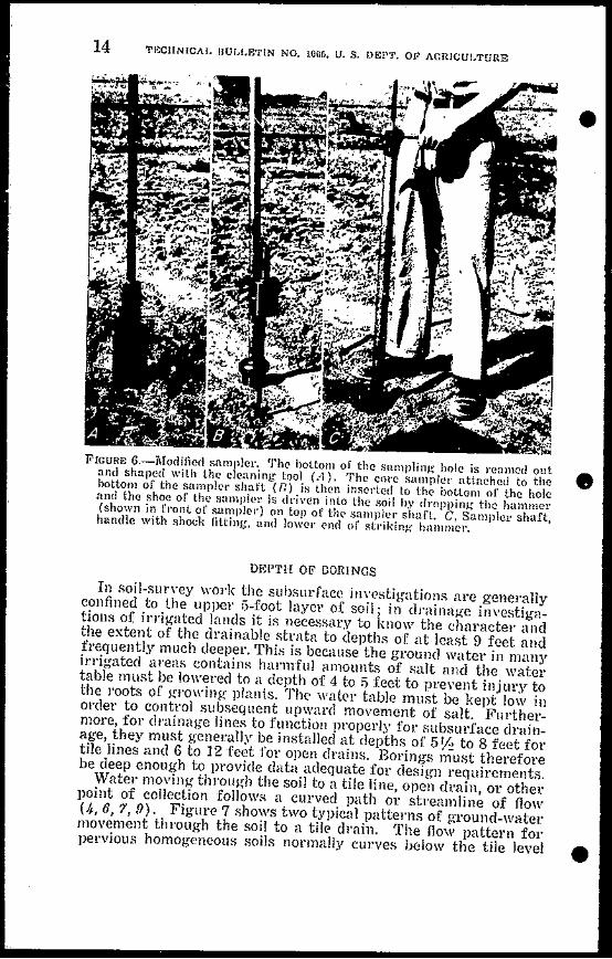
bullbull
--J
DRAIN~GE INVESTIGATIQN METHODS FOR IRRIGATED AREAS 15
and back up to the tile whereas in stratified fine-textu~d soils the streamline flow may he sharply restricted Thus j the presence of lmiddotestrictive soil layers partly determines the spacing of tile lines and the optimum depth at which they should be placed Adequate information on the character of the deeper soil layers may obviate the error of locating tile lines in or below impervious strata Inf01middotshymation on soil strata to depths of 8 to 10 feet is essential for the design of tile systems to depths of 10 to 15 feet for open drains to depths of 15 to 25 feet for sumps and shallow wells and from 25 feet down to the proposed depth of the well for drainage byl11Eans of pump wells
In farm-drainage investigations it is well to keep in mind that
~ I bullmiddotl middotmiddotrmiddot middot I bull r~middotw ~bullbull ~rmiddotmiddot jyOn middotmiddot-middot1middot I I 1 I I 1 I I I 1 I I I I I I I I I I I I I I I I I I I I I I I I I I I I I I I I I I I I I I I I I 11 I A I 1 1 Iii II i I I I I I I I I
I I I I I -- ---~~~9f~~~- __ ---~Q~~lt-_ ~~~bullbullbull~ loi ~~)t~~(~ bull bullbull m IIIn ~H bullbullbull ho
bull HIINItIIW IOtINt iVtHtIHIIlUVtJIIIIf
kotmiddotmiddotmiddotuII middotI~IIIlIII 111 IIUII N~ 11 itt IIIII ~ lto rt
I1ImiddotUlIIn If v 11 I f bull bull bullbullbull vbullbull f
ulllI HltoH bullbull hrU II 10 bullbullUI OUII ~nmiddotIHn ntl
ImiddotIIIIVII h IMPERVIOUS CLAY STRATUM middotIIHIII oJ H~ UlOII i IHuU iI II t fj IHI I
bull~I H Ih bullbull 1 Iull IJ 11bullbull11 H If II ~ lu bullbullVIi U II ~
bull If~ J 1 10 vt1 1 011 bullbull u bullbullbulli If 1 bullbull j
11 h~ ffHI nlll U V(jf It~ bullbullbull 1 iI to ~ bullbull bullbullbullH
FIGURE 7-Lines of flow to a series of drain tiles A In an aquifer overlying an impervious clay stratum n in an aquifet~ without an impervious clay stratum or other harder
213H7D-53-3
middot
16 rECHNICAL BULLETIN NO 1065 U 8 DEPT OF AGRICULTURE
one 12-foot hole is better than two 6-foot holes and at least one 9shyfoot hole should be bored on each 10 acres
RECORDING BORING DATA
A log should be made of each hole bored preferably at the time the boring is made At the same time the location of the hole should be marked on the map of the area as an aid in delineating the boundaries of different types of drainable or undrainable soils
Survey notes which should be made as the boring progresses should include information on the depth to water table the relative moisture content of the various strata the degree of staining or discoloration of the soil particles and the )resence of roots and minerals Where core tubes are used notes should be made of the soil structure minute stratification and the presence of lenticules Or sand-filled cracks that help to improve permeability in the clay parts of the soil profile and if the boring is in sand strata of minute layers of silts or clays that tend to slow up the movement of water
The identifying characteristics of a giYen soil once determined can often be used to classify and delineate similar strata elsewtere For example the minute shells typical of the best sand aquifer material in one part of a large irrigated valley usually serve as a good indicator of favorable drainage properties in the sand strata of other parts of the same valley Thtls certain strata of soils can sometimes be traced over an entire drainage area
Identifying soil characteristics helps to maintain a high degree of consistency in subsoil mapping in which several technicians take part and tends to reduce day-to-day variations in accuracy of observation by the same individual These soil characteristics may also be used to roughly gage in the field the relative permeability of the various soil layers as an aid in preparing the permeagraph previously mentioned
A convenient method of plotting the logs of a series of borings is to draw a profile delineation of the underground strata Such a chart helps in determining the relation of the dip and slope of the clay and sand layeni to the slope of the ground surface to the varishyous topographic features and to the slope of the water table
The position of the water table in relation to the soil strata as determinfd from the borings is readily seen when the vater table js plotted on the profile-delineation chart The exact series of profiles to be used in the charting depends on the nature of the drainage problem In mountain alleys it is essential to draw several delineations down slope in order to locate accurately the underground extension of water-bearing aquifers that crop out to the surface Where tile systems are planned a profile delineation should be drawn along the general alinement of each tile line
A method of depicting the boring data for mountain areas is to locate the several boring sites on a hUge-scale map of the problem area and insert a small-scale columnar chart of the log at each boring site shown on the map Distinctive eolotmiddots or other markings are used to show the thickness of the respective strata A study of
bull
bull
bull
DRA1NAGE lNVESTlGAT10N METHODS FOR lRRlGATED AREAS 17
the map and related data will reveal the optimum location for drains
Important layers of heavy clays or coarse~textUled sands that are continuous over large areas may be plotted to advantage 011 a subsurface contour map For example a continuous stratum of fine-textured clay may underlie a coarser drainable soil at depths varying from 4 to 8 feet below the surface Plotting the upper surshyface of the clay layer on a contour map locates the low valleys of the relatively impervious layer Such information facilitates the planning of a drainage system that will drain all the area with a minimum footage of drains
SOIL-PERMEABILJTY DETERMINATIONS An estimate of the permeability of the strata underlying the soH
surface is essential in developing sound techniques of land dlfin age Water-transmission rates should be determined in quantita~ tive terms to be of practical use in this connection
COEFFICIENT OF PERMEABILITY Coefficient of permeability may be defined as the rate of flow of
water through a unit crolgts-sectional area uuder a unit head during a unit period of time For convenience in making comparisons coshyefficient values are stated in terms of flows of water throughsaturated soil
Methods of accurately determining the coefficient of permeshyability may be grouped in three broad classes as follows
bull 1 Field measurements (a) Direct measurement of the permeability of an entire
soil profile based on pumped~well data A drawshydown curve and data on quantity of water pumped are used to compute the coefficient (13)
(b) Direct measurement of the permeability of indishyvidual strata by means of small tubes piezometers 01 auger holes (5)
2 Laboratory measurements utilizing a permeameter device and either in~pla(e undisturbed specimens taken in the field by means of one of the various sampling devices or samples of dilgtturbed soil prepared for laboratory examina~ tion by dryi)lg the soil and packing it into the permeashymeter
3 Indirect evaluations of permeability based on physical and chemical soil properties
Each of these methods has its merits and draw-backs The par~ ticular method selected will depend upon the requirements of the drainage survey the availability of appropriate measuring devices and the degree of accuracy desired
FIELD MEASUREMENTS OF PERMEABILITY-The determination of subsoil permeability by means of direct field measurements makes use of formulas based on the flow of water through the soil to a discharging well A basic assumption of these formulas is
bullthat the cone of depression representing the pumped water table around the discharging well is in equilibrium ie the discharge
t
i
bullbull
(i
TECHNICALmiddot BULLETIN NO 1065 U S DEPT OF AGRICULTURE
r~semt1on ells
StaticJUlr _ I-- -- - f--r - -- 1----1 - shyfable
5 ~ _- _ 40---+--_shy____ -=ifshyr---
pgp1~ ter fable V
h
I ~
Aquiler bull
FIGURE S-Diagram of factors involved in calculation of permeability coshyefficient from field measurements with well extending thrQugh aquifer to barrier stratum
from the well balances the inflow from the water-bearing stratum To secure the field data a stratum survey is made of the proposed well site a small well is put down to tap the aquifier and a system of observation wells is laid out around this well The well is then pumped until equilibrium is reached between the discharge and the drawdown around the well
The measurements needed to evaluate the permeability coefficient are the quantity of water (Q) obtained by measuring the well disshycharge the hydraulic gradient (I) as determined by the position bull
19 Q-
DRAINAGE iNVESTIGATION METHODS FOR mRiGATED AREAS
of the draw-down curve for the observation wells and the area of fio (4) as determined by borings The coefficient of permeability (P)is calculated using an adaptation of the Darcy formula
In simplifieurod form the adapted Darcy formula is Q = PIA Assuming that the well extends through the aquifer to the barrier stratum the formula is expanded to
Q 1og IfR2
P= __~__~~~~1~-=~ 1f (h2 + hI) (S1 - S2)
The dimensionless factors entering into the solution of this formula are shown in figure 8
The soil water table and other hydro)ogic conditions under which this formula may be used have been stated by Wenzel (13) as follows
A water-bearing bed of uniform permeability is assumed to rest on a relatively impervious formation of indefinite areal extent A well equipshyped with a pump extends to the bottom of the water-bearing material and two observation wells are placed on a line with the pumped well The pump is operated at a uniform rate during a period in which the water table declines and takes a form similar to an inverted cone around the pumped well The nonpumping water table and the underlying impershyvious bed are assumed to be horizontal
Various modifications of the basic Darcy formula of flow of water through soil are used depending on the site conditions and the measuring techniques employed Modifications are necessary for example for flows from confined aquifers or from aquifers under artesian pressure The use of this method must be varied also lor aquirels which are not uniformly permeable horizontally and vertically And in any event of course its use is limited to areas in which the water table is high enough for practical pumping
The mathematical explanation of the derivation of the various formulas applicable to specific field conditions including the derivashytion of the formula mentioned above is fully described by Wenzel al1d other workers in the field of hydrology and will not be Ret forth in detail here
In another type of field measurement water is introduced through a pipe or well of small diameter that taps the soil stratum to be investigated 311d the rate of flow is measured A variation of this technique is to pump the water out of the tube and time the rate of leCOvely in the tube Frevert and Kirkham (5) described a method for measuring the permeability of the soil below a water table
Although they probably provide the most accurate permeability coefficients field measurements are relatively time-consuming Furthermore the field sites for the measurements must be carefully selected LABORATORY MEASUREMENTS OF PERMEABILITY~Laboratorymeasshyurements likewise are highly accurate when in-place samples are used but they too require much time and in addition considerable
bull special equipment They may be made either by the use of in-place undisturbed cores taken in the field and brought to the laboratory
20 TECHNICAL BULLETIN NO 1065 U S DEPT OF AGRICULTURE
for tests or wifh samples of disturbed soil that have been dried reshyduced to granule size and then packed into a permeameter tube for testing Both methods require special tools and equipnlent and rigid conformance with standard procedural techniques as described by 1fuskat (9) and other workers In solving drainage problems of a difficult nature and those in which high values are at stake the use of the more time-consuming complicated and expensive laboratoryinvestigations usually is justified Fallin Head Pelmewmete1-The falling head permeam~ter is an instrument suitable for use in the field or in a field office laboratory to obtain quick and reasonably accurate measurements of permeshyability A permearneter of this type patterned after a similar device used by the United States Geological Survey (13) was developed for use in Imperial Valley Calif4 lhe device consists of a soil column and a water column connected by a L-tube and of measuring and other attachments Water is introduced into the water column From there it flows through the U-tube into and through the soil at a iowel elevation in the other columlL The rate of flow is a measure of the permeability of the soil
The Model-A type (figs 9 A and 10 A) consists of a 2-inch brass soil cylinder connected at the base with a small copper U-shaped tube to which is attached a glass manometer tube An auxiliary water-supply cylinder is connected to the U-shaped tube to furnish water for the tests Water is allowed to pass from the supply tube to the soil tube until it saturates the sample and begins to flow over the top rim of the brass cylinder The supply valye is then turned off and the rate of the drop of the water in the graduated glass tubes is noted This rate of drop is an indication of the permeabilshyity of the soil
The Model-B type (figs 9 B and 10 B) is constructed of materials that are readily available in most localities The soil cylinder is made from a short length of 11-inch smoothly reamed pipe This is threaded to a 114-inch coupling which in turn is attached to a series of reducers nipples elbows and other fittings This device is relatively inexpensive costing approximately two dollars for the material The fittings may be obtained in any plumbers shop and can be assembled with a pipe wrench and soldering iron A coating of stopcock grease is applied to the threads on the end of the soil tube to prevent leakage
Figure 9 shows details of construction and gives the dimensions and material lists for permeametel types A and B respectively Figure 10 illustrates the assembled permeameters and parts
The soil tubes of both models being demountable from the rest of the device can be used to obtain undisturbed soil cores for testshying purposes without dismantling the entire apparatus or taking it to the sampling site
In-place samples are obtained by pressing the sampling tube into the soil with a hydraulic j~ck Side friction and resultant compresshysion of the soil sample can be greatly reduced by wetting the soil
of Bradshaw G B and Donnan T W A Falling Head Permeameter for E-aluating Permeability U S Dept of Agric Soil Conserv Service 1950 (Processed)
bull
bull
bull
bull bull ~~~c
~~
o 0 0 0 0middotmiddot8 o 0 0 1 ~ ---Y
9
~~~Ddeg o 0
~5middotbull L ~A ampCHID) ) bull middot amp r~ ~~ rw HOI[ Jln ~ 1~~1
Tz_rti~v ~r SUfO ZU)it VI
middot ~ L
Ilbull bull ~
middotbull
B
---L ~
0I I I ~_LI
1 ___ ___ J
QO
-
t1 liS gt ~ sect
i r 111amp-shy
~ LI~~middot~a L
i bull ~111t-t1rOOfT~
114100
~1J~~~l 11 n_
01 cWtllI
cl i
gt ~ ll( tl
~ ~s
~
FIGURE 9-Construction details and materials specifications for falling head pellneameter A Type ~ A S type B ~
~
~tgt V C bull -~~ ~~
22 TECHNICAL BULLETIN NO 10G5 U S DEPT OF AGRICULTURE
tube prior to sampling Vertical samples can be obtained by using
the car bumper as a backstop for the jack In order to obtain horishyzontal samples it is necessary to dig a sampling pit and push the sampling tube into the side of the pit with the jack using the bullopposite wall of the pit for leverage Veltical samples can be taken to depths of 8 to 9 feet with the Model-B sampler by first boring a hole with a post-hole auger and then using a 1 Y2-inch pipe-extenshysion handle on the permeametel soil tube
In both shallow and deep sampling the samples should be careshyfully removed from the surrounding soil and the extruding soil gently broken away The ends of the samples are then trimmed
bull
FIGURE lO-Two types of perl11eametcls A Type-A permeamctel and parts 1 Assembled insttument 2 dismantled permeameter 3 cap used for jacking soil tube 9 into Roil 4 cap scrcws 5 ring to hold soil tubcin Jllace 6 scrcen and filter 7 cutting cdge for in-placc sampling 8 scating and rcaming tool 9 soil tube fl Asscmbled type-B pcrmeamctcl
with a spatula or other tool a paper filter is placed over the bottom end of the sample next to the soil and this in turn is covered by a screen to keep the soil from sloughing away The tube containing the sample is afTixed to the permeameter and the connections are tightened to prevent leakage A small weep hole at the point where the screen and filter join the soil sample is used to bleed the ail from under the soil sample and prevents ail from being forced through the sample As soon as the soil column is saturated the sample is bull
DRAJNGE INVESTIGATION METHODS FOR IRRIGATED AREAS 23 ~
ready to be tested Satisfactory results are obtained by using irri~ gation water for the permeability test
The size of the glass manometer tube to be used depends on the permeability of the soil to be tested For freely permeable soil a tube with a diameter of l15 55 01 75 millimeters is most suitable For slowly permeable soils a smaller tube of 1 2 or 3 millimeters should be used The device is so constructed that these glass tubes are interchangeable
The permeability of the soil sample is obtained by noting the time required for the watelin the glass manometer tube to fall from an initial head reading to some other desired head reading Computations are simplified if the initial head is set at 115 centi~ meters and the final head 5 centimeters resulting in a head difshyferential of 10 centimeters In testing slowly permeable fine-texshytured soils an ordinary watch with a second hand may be used for timing for more permeable soils a stop watch is needed
The coefficient of permeability is calculated by means of the following equation
d L hP =23025J - log _-_lt (3-600)D~ t 10 h
in which
bull p is the coefrkient of pelmeability in cubic centimeters pel
square centimeter pel hour d is the diameter of the glass tube in centimeters D is the diameter of the soil tube in centimeters L is the length of the soil tube in centimeters t is the time of fall of water f1ol11 110 to h in seconds to is the initial head in centimeters h ii the final head in centimeters and 3600 ii the factor for cOlwerting the result in second-units lo
hour-units Obviollsly fOl any given type of falling-head device many of these factors are constants TemlJ81aiw( cOlleclioll-The coefficient of permeability is defined for a water temperature of GOdeg F If the test is made with watel of ~lny other temperature the calculated coefficient must be corrected for the difference in Yiscosity of liquid due to higher or lower temshyperature lhis correction is necessary because the viscosity becomes less as the temperature rises and the rate of flow of water through the soil increases Viscosity is inversely propoltional to both temshyperature and permeability For each degree of temperature variashytion above 01 below GOdeg F the correction is made by multiplying the unadjusted calculated coefficient by the proper correction factor
The temperature-correction factors for converting coefficients of permeability computed at water temperatures of 40deg ot 90deg F to
bull coefficients of permeability at water temperature of 60deg F are given in the following tabulation
J
1 I
TECHNICAL BULLETIN NO lOGo Ubull S DEPT OF AGRICULTURE24 ~
of C011()ction of CltnIecfion of C011ection factm factor factor
40 137 57 ___ ___ _ 104 74 083 11 135 58 _ _ _ 103 75 82 42 133 59 _ _ ____ 101 76 81 43 131 60 ___ 100 77 80 44 128 61 ___ ____ 99 78 79 45 126 62 _ ____ 97 79 78
63 _________ 9646 124 80 77 47 122 64 ______ 95 81 76
~ T 48 120 65 _ _ _ _ 93 82 75 49 118 66 ___ 92 83 74 50 116 67 91 84 73 51 115 68 89 85 72 5~ 113 69 _ _ _ 88 86 71 53 111 70 _ __ 87 87 70 54 109 71 ___ 86 88 69 55 108 72 __ 85 89 68 56 106 73 84 90 _ _ 67
Results of tests-The most reliable and consistent measurements of the permeability coefficient h~e been obtained by the use of unshydisturbed soil samples taken ill place Laboratory-packed samples are less suitable since the same degree of compaction is difficult to obtain in aU samples Comparative test runs with in-place and packed samples reveal that for sand there is a fair correlation but for fine-textured soils the difference in results may vary as much as 500 percent
In using the in-place technique it is desirable to use both horishy bull zontal and vertical samples The flow of water horizontally through the soil under some conditions may be much greater than the flow vertically This is due to the tendency of certain soil particles in settling out of a suspension to fall with the flatter sides overlapshyping each other resulting in a shingle-like arrangement of the soil particles in the deposited stratum The bedding of soil particles in microscopic horizontal strata tends to impede vertical flow and thus t~nds to give higher coefficients for in-place samples taken in a horizontal direction This tendency is important because in actual practice drainage design is based mainly on flows to tile lines or open drains in a horizontal 01 nearly horizontal direction
For practical dr1inage-investigation purposes short-term test runs of about 1 hour on saturated undisturbed samples give a sufshyficiently accurate indication of the coefficient of permeability Alshythough many research workers feel that the only true test of flow of water through the soil requires a run of several days a comshypilation of permeability data for 26 different in-place samples of soil from Imperial Valley Calif showed that long runs were not essential for reasonably accurate determinations (table 1) The samples were taken in horizontal vertical and diagonal directions These runs were carried on for periods ranging from 96 hours to 906 hours Yet in a majority of the tests the measured coefficients of permeability at the start of the runs were only slightly different bull
~ laquo ~l ~~ -gt ~ ~
25
bull
bull
yen
I
DJiAINAGE INVESTIGArIOJ~ lttETHObs FOR IllRlGATED AREAS
from the actual average coefficient based on all the observations during the lmiddotUll
TABLE 1- Results of meaimIements of coefficient of pelmeability of soils) l1nperial Valle1l1 Calif1
CI Coefficient of permeability inUl TotalotDSample QJ5 houls cubit centimetetmiddots pel square eentimetpl pel hour
gt=~No ~s4-5 Tun Start of run End of run Average3 P-4~
of
I I 46-C1 H 214 1865 1472 1700 46-E2_ V 18r 313 524 478 46-E3_ H 188 710 1140 1085 46-D1 V 165 1100 1150 1112
Ul
46-D2__ H 120 1159 755 855 96-A H 284 115 157 137 96-A2 V 281 62 230 131 96-E H 284 73 168 123 122-A H 310 1408 1405 1395 122-B V 96 789 868 842 122-G V 906 1]75 750 914 123-A_ H 117 1115 1605 1150 123-Bbull H 116 1205 1105 1185 123-B H 342 1380 1044 1215 123-C_ _ V 146 867 1149 943 123-G V 169 868 652 736 125-A H 162 1370 14l5 1422 125-B V 841 885 714 865 149-A V 340 1090 7l1 1013 149-B H 362 778 840 809 149-C D 339 1130 1340 1151 150-A H 303 1810 2180 2241 150-B V 339 764 645 823 213-A H 483 77 56 71 213-B H 146 145 173 147 213-C V 479 106 75 103
1 Data from Preliminary Progress Report of Cooperative Investigations in Imperial Valley Calif 1943-44 by W W Fox V S Aronovici and W W Donnan Soil Conselv Service 1944 (Unpublished)
2 H-holhontal V-vertical D-qiagonal 3 Average based on all observations taken during the test
INDIRECT EVALUATIONS OF PERMEABJLITY-Some of the soil charshyacteristics that control the movement of vater through the soil are type of structure arrangement of aggregates grain size texture pore space dispersion swelling and type of clay mineral In many sections of the country including western United States visible soil characteristics have been correlated with measured percolation rates and the soil permeability is graded in accordance with a classification which has been used extensively by the Soil Conservashy
bull tion Service in describing mapping units of soil conservation surshyveys This classification follows
26 EEClINICALDULUJjJN NO 10M U S DEI OF AGJUCUIfjURE
larcolatioi r([il in i-chen Jmrmiddot hour Permctlbillty trouf satltrllted i8ltTHld corCB
Permeability clas8 illdo dcr IC hea of 10Mcr
Very slow _____ 1 Less than 005 Slow _ ______ 2 005 to 02 Moderately slow ____ 3 02 to 08 bullModerate __bull____ 4 08 to 25 Moderately rapid ____ 5 25 to 50 Rapid __ _ bullbull___bull 6 50 to 100 Very rapid _____bull 7 More than 100
t Estimating the permeability of significant soil zones below the topsoil by correlation with visible soil characteristics provides a means of delineating the general boundaries between drainable and undrainable strata The approximate ratings must be supplemented by actual field measurement~ however jf precise quantitative values of permeability are required Indirect evaluations such as these by which permeability is graded according to distinctive and
J easily observable soil characteristics are suitable only when sufshyficient correlations have been made between soil characteristics and water transmission rates in a particular locality to furnish a reshyliable base for the permeability estimates
WATER-TABLE INVESTIGATIONS
The water-table survey provides essential information on the position of the water table at different points in the problem area and in the various soil strata and on the extent and degree of severity of the drainage problem in general Ground-water flow patterns are prepared from the piezometric data obtained These flow patterns fUll1ish a good basis for the design of improvement bullworks
EXISTING DATA
Records of water levels maps of depths to water table and other hydrologic data for past years are available for many drainage problem areas Such data when correlated with current conditions often furnish clues to the cause of fluctuations in the water table The plotting of water-table hydrographs in conjunction with data on precipitation irrigation runoff effect of pumping and other hydrologic phenomena provides a useful basis of analYRiR
OBSERVATION WELLS
Unfavorable water-table conditions are often indicated by cershytain well-recognized symptoms Thus poor crop production and the presence of marshy areas or alkali spots usually are visible evidence of waterlogging The use of observation wells however is necesshysary to obtain positive data on the position and fluctuation of the water table
The type location and number of observation wells to be inshystalled depends on the type of informatiol1 needed The most comshy1110n types are open holes bored with a soil auger 01 post-hole auger or wells drilled with a commercial rig Open holes made in the course of soil surveying can also be used for this purpose Open bull
bullbull
middot
bull
DRAI~AGE Il-lVESTIGArwN MElHODS FOR IRRlGNlED AUEAS 27
wells if they are to be used for any length of time should be cased to prevent caving Casing materials range from thin sheet-metal pipe stovepipe and drain tile to the standard commercial types of well casing
The kind size and depth of well and the type of casing depend largely on the type of investigation being made For a reconnaisshysance of a small plot of ground auger holes usuaily suffice for a valley-wide drainage investigation observation wells of a semishypermanent type should be installed The mot effective system for a valley-wide investigation is a series of wells in a grid pattern oriented to the strata-survey grid to facilitate correlation with soils data
Observation wells are generally installed by placing the pipe or casing in an auger hole dug to the desired depth as shown in diashygram A of figure 11 Casing pipes range from inch to 6 inches in diameter Pipes open only at the ends should be set on a small quantity of gravel at the bottom of the hole Gravel is then backshyfilled around the pipe to a point above the ground-water table Native material may be used to fill the remaining portion of the hole to the ground surface The pipe is left projecting 12 to 18 inches above th( ground surface and is covered by a pipe cap to protect the well
PIEZOMETERS
A most useful drainage-investigation tool is the ground-waterpiezometer an unperforated small-diameter pipe so designed and installed that after it has been driven into the soil the underground water can enter it only at the bottom end (12) The device regisshyters the hydrostatic pressure of the underground water only at the bottom of the pipe Almost all types of cased wells on the other hand are perforated throughout their length or have numerous access points for water to pass from the soil to the well In an open uncased hole 01 ordinary cased wall therefore water seeps in at all points and fills the hole to whatever height the strongest hydroshystatic pressure will produce Such a well registels the depth of water or hydrostatic pressure in the entire soil profile penetrated by the well Diagram B of figure 11 illustrates this fundamental difshyference between the piezometer and an ordinary well
The availability of an instrument like the piezometer which can be used to ascertain the hydrostatic pressure at any level in the soil profile opens up a wide range of possibilities in drainage investigashytions Since underground water moves from a point of high hydroshystatic pressure to one of low pressure the movement of water can be charted if the hydrostatic pressures are measured With sets of piezometers spaced at intervals the hydrostatic pressure at difshyferent points in an entire profile may be determined and seepage movement detected Under certain conditions a single piezometer may be used to reveal seepage as when a piezometer pipe is inshystalled in the soil in the center of a flowing canal or drain If the water level in such a piezometer is higher than that in the canal it may be an indication that water is seeping from the lower level soil into the canal
0
OBSERVATION WELL PIEZOMETER WELL DRIVING HAMMER
r- r- ~tQ PIEZOMETERGROUND -tilSURFACE oGROUND SURFACE~ -1 = ~ Z
~~ t ~~ PIPE ci
I I c t_~UND_ _~~E -1__L -~EL t
~--~l- -11111 =tII
Z III
~sectl --+ I III - z ~I 1I11I
e -)--
shy
i -1111 -III ~-111- CA POST B iL PLUG
HOLE til III
rnJ -c- CAVITY FORMED dARROWS INDICATe BY FLUSHING ~It
~
GROUND WATER ENTRANCE -II) LI 34 PIPE
1 THE PIEZOMETER INDICATES THE PRESSURE AT THE POINT OF ENTRANCE RATHER THAN C)LrY o
gt THE LEVEL OF THE GROUND-WATER TABLE
g ~
GRAVEL BACKFILL ALLOWS ENTRANCE THE WELL INDICATES THE LEVEL OF THE OF WATER FROM ANY POINT SURROUNDING GROUND- WATER TABLE
~ ~
~
FIGURE ll-Some details of observation wells and piezometers A Cross-section view of observation well showing proper method of backfill B diagram illustrating fundamental difference in flow of underground water to well and piezometer C detaifs of piezometer driving hammer and method of installation (from Ground-Water Studies in Relation to Drainage by J E Christiansen)
-
_
-j-ibullbull bull bull
29
bull
e
DItAINAGE INVESTIGATION METHODS FOIt IfHUGATED AREAS
DESCRIPTION OF PIEZOMETER The ground-water piezometer consists of a standard 14- or shy
inch iron pipe driven vertically into the ground to a definite level Before driving is started a loose rivet is placed in the lower end of the pipe to keep soil from entering When the desired depth is reached a jointed rod is inserted and the rivet is punched out leaving an open pipe or piezometer In some soils the prptecting rivet is not needed Before driving the exact length of the pipe should be noted so that the elevation of the bottom of the pipe after driving may be determined
The driving is done with a special hammer fashioned like a steel fence-post driver It consists of two pieces of -inch pipe 15 inches and 5 feet long respectively joined by a 1-foot section of 1 lh-inch pipe filled with lead (diagram C of figure 11) This leaded section is fitted with a steel plug at each end to receiye the impact of the blow The top of the piezometer pipe is fitted with a removable -inch driving head The piezometer is started into the ground with the 5-foot end of the hammer over the driving head of the piezometer When the top of the piezometer has been driven to within 5 feet of the ground surface the hammer is inverted and the drivil1g continued until the top of the piezometer is at the desired elevation about 1 foot above the ground Piezometers may be driven with a pneumatic jackhammer if the top of the piezometer pipe is fitted with a driving cap for seating the jackhammer pilot Power driving makes it possible to install piezometers to a depth of 30 feet even in very heavy soils Figure 12 A shows a piezometer being driven with a jackhammer
The deeper the piezometer penetrates the soil the greater will be the friction on the sides Since hand driving of even a 15-foot piezoshymeter in some soils may entail considerable laber the use of this method is definitely limited Placing a joint and coupling about 1 foot from the bottom of the pipe slightly enlarges the hole through which the pipe passes as the piezometer is forced down This helps to reduce side friction and cuts down the resistance to penetration The use of such a coupling permits driving of piezometers by air hammer to depths of approximately 40 feet without causing leakshyage down the sides of the pipe and a resultant los~ of benefit from the piezometric principle Earth from the side walls of the hole closes up the enlarged space surrounding the pipe above thE coupling The 1-foot section of pipe below the coupling is of course ealed at all times against any leakage
Piezometers should be driven as nearly plumb as possible Single lengths up to 14 feet may be installed by working from a stepshyladder For greater depths several sections of pipe are joined with standard pipe couplings the maximum depth of installation being limited only by the difficulty of driving the pipe and removing the rivets
FLUSHING For sllccessful installation and operation of piezometers the
soil at the lower end of the piezometer should be removed by flushshying leaving a small cavity at the bottom of the pipe as shown in diagram C figure 11 Flushing is done by punching the rivet from
bull bull bull
o
tl o z Qgtshyrshycc t t
~ Z z ~
~ S c tl ~ o
gtshyCi ~
(=jc
~ C
FIGURE 12-Driving and jetting piezometers A Driving 14-inch piezometer with an air hammer Tubing in lO-foot lengths may be joined and sunk to a depth of 30 fect by this method fl Jetting] 2-inch piezometcr Coachella Vallc~r Calif
lt
j
bull
gt
J)RAINAGE INVESTIGAflON METHODS FOR IIUUGAtEIgt AUEAS 31
the lower end of the piezometer by punch rods after the pipe has been driven to the desired depth then cleaning out the pipe by pumping water into it through a flexible tube The water escapes by flowing upward through the narrow space between the tubing and the inside wall of the pipe The equipment needed includes a water container stirrup pump and enough plastic tubing l4-inch in outside diameter to reach the bottom of the deepest piezometer used (fig 13) The tubing is marked with colored lacquer at I-foot intervals
rmiddotbull
~
r
~ I
FIGURE 13-Some equipment used in piezometer and well investigationsLeft to 1iuht StilTup pump and plastic tubing for flushing electric watershylevel indicator for piezometer sounding bell for 1-12-inch and larger pipes sounding rods usable also as punch rods for lemoving rivet from piezometer
The plastic tUbing is pushed down inside the pipe during pumpshying until it nears the bottom then gradually lowered until the end is about even with or slightly belOW the end of the piezometer~ Flushing is accelerated by working the tubing up and down care being taken to avoid lowering the tubing beyond the depth specified The water that overflows the pipe is usually very silty at first With continued pumping however the water clears The tubing is then slowly withdrawn while pumping continues
TECHNICAL BULLETIN NO 1065 U S DEPT OF AGRICULTURE
The piezometer is tested for sensitivity by filling the piezometer I~ pipe and observing the rate at which the water drops Experience
will soon indicate the approximate rate to be expected If the rate of drop appears too slow the flushing is repeated the tubing being bulllowered slightly below its previous level to enlarge the cavity In l1ighly permeable sands piezometers take the water so rapidly that no overflow occurs whereas in some soils of low permeability the rate of subsidence of water in the piezometer is hardly perceptible In some instances an equilibrium level is obtained in a few minutes in extreme cases 24 hours or more may be required
In some soils piezameters may be driven to advantage without rivets Although plugs of soil 6 to 8 inches long may pack in the lower end they can be flushed out in less time than would be reshyquired to punch out the rivets
Piezometers may occasionally seal up after being in use for several months Erratic variation in the pressure reading of any piezometer as compared with others in the same vicinity may indishycate sealing which can be readily overcome by reflushing
JETTING PIEZOMETERS
Both piezometers and wells have been installed successfully in certain areas to depths of 100 feet 01 more by jetting (10 11) Figure 12 B illustrates jetting- equipment designed and built for use in connection with cooperatie drainage investigations in Coachella Valley Calif Much greater depths can be attained by jetting than by driving the depth of installation being limited mainly by the size of the aggregate encountered Some highly bull porous formations take the water faster than it can be pumped down and 110 deepening of the jetted hole results
In jetting the soil is removed by flushing it up around the pipe and out of the hole Although this may result in side leakage and cause the pipe to act as a regular well when the well is new the sides seal up after a period of time and the well then functions like a piezometer The difficulty of determining the extent of the seal along the sides of the pipe makes it hard to determine whether the readings obtained are from a well or a piezometer Nevertheless jetting is a quick and easy way to install a deep observation well and the ease and economy of installation far outweigh the limitashytions
REMOVAL OF PIEZOMETERS
Piezometer pipes may be used many times over if care is taken in removing them from the ground Lengths up to 8 feet usually can be pulled by hand after they have been loosened by turning with a pipe wrench For deeper installations the pipes are easily exshytracted by means of a ratchet hoist suspended frol11 an A-frame or tripod of 2- by 4-inch material (fig 1lt1) A set of small metal grippers is fastened to the piezometer and attached to the pull chain of the hoist After removal the pipe should be cleaned of soil and corrosive scale straightened and if non galvanized covered with a light coating of oil to prevent rllsting
The piezometer tube may also be raised with an ordinary soilshy bull
33 DRAINAGE INVESTIGAT()N METHODS FOR JHRiCAlEIJ IEAS
bull
bull
FlGCRf 14-Ratcl1lt hoit tlipod and glippC) used in (gtxtracting d((p pi(Z(lIl1lttI pjPt~
tube jack using a S(lt of sl1lalll1lltal grippers fittcd around the pieshyzometer pipe to provide a btHling sUJfaec fol the jade
MEAseRIXG DE1(ES
There are lJlany differcnt methods of measuring the water elenltion in OIJiienution wells and pieometcls For 11 ~-inch and laJger pipes a sounding b(1 (lig ]3) can be utilized The bell is made by boring out th ((nLer of a l-ineh-c1ial11etel brass rod to a depth of 1 inch until the walls aJe approximMely 1 i32-inch thick A I~-inch shank is formed by turning clown the end of the rod for about l ~ inehes and ~pttilJg a Jin in the end A brass chain about 0inChes 10llg is used to join t11( b(11 to the low-reading end 0pound a metalli( tape Ir it lulJ-lengtJl Lapp is used without foreshortening a correction must )( applied to the watcl-t(ation reading- to COIll shy
bull l1ensate 101 the 1ltIlgth of the sOLinding 1)(11 and ehain As an alternashy
~~
TECHNICAL BULLETIN NO 1066 U S DEPT OF AGRICULTURE34
tive a piece of the tape equal in length to the combined length of bell and chain may be cut off before it is fastened to the chain The tape then gives direct readings The bell is lowered on the end of the tape until the sound of the bell which is clearly audible as much bull as 100 feet from some wells indicates that it has contacted the water surface
A relatively simple adaptation of the sounding bell described above designed to facilitate the reading of open uncased holes made with soil augers has been used successfully in wells of small diameter The bell of this device is made by brazing a large cartshylidge case similar to a 45-70 to a jointed 1b-inch rod The rod is graduated and marked as desired
The depth to water in piezometers and wells may also be sounded by lowering a length of plastic tubing into the pipe while air is being blown into the free end of the tUbing above grutdd When the tubing touches the water an audible vibration is set up in the pipe The water level may be determined either by withdrawing the tubing and measuring the length removed or by using a tube on which unit distances have previously been marked with differently colored lacquers
WATER-LEVEL INDICATOR FOR PIEZOMETERS
The type of sounding device commonly used for larger observashytion wells is unsuited for use with piezometer pipes of small diameter A satisfactory electric water-level indicator has been developed for this purpose (fig 15) The essential parts of the deshyvice are a flexible rubber-covered wire marked with I-foot gradua- bull tions small penlight batteries for current and a milliammeter 01 voltmeter to indicate the closing of the electric circuit
The wire should be highly flexible well insulated and not easily kinked Type FF single-conductor flexible cord is satisfactory
The end of the wire is equipped with a weighted sounder tip made from about eight lengths ofYi-inch brass tubing each section 11 inches long This flexible end permits the plumbing of bent and damaged piezometers The insulated contact wire passes through the series of tubes and is soldered to a metal tip This tip is inshysulated from the brass tubing with a piece of lucite machined to fit into the end of the tubing The wire is marked at I-foot intervals with bands of colored lacquer to indicate successive foot readings It is held on a reel and passes in front of a fixed scale 1 foot long graduated in tenths and hundredths of a foot This scale reads from the top down so that readings are obtained directly to 001 foot A reel harrow enough to accommodate only one width of wire has been found most satisfactory
A milliammeter of 0-25 milliampere range is well adapted as an indicator although a high-resistance voltmeter also gives satisshyfactory results For ground waters that contain a relatively large amount of dissolved salts a single battery cell furnishes sufficient current to give a satisfactory reading for waters with weaker concentration of salts two cells may be required
The instrument is so arranged that when it is seated over the top of the piezometer pipe the readings give the distance from the top bull
GOIITACOT 11124 SKEET R~ I l~~
MILLIAMMETER O-ZS REAORITE D C ADJUSTABLE
IATTEIIY TUIE S O D IY II I D rUle IRASS WIT LUCITE OR EQUAL END FITTINGS LENGrli
A
CENTIIAL STFF 34 O D IY 51 I D TUIE IRS5 LENOT ZO bull
IItMOVLE INNEII SLEEVE 111 o D IY sl I D TUIE IIIASS LENITH 4 lIz
RIGHT
bull REEL Iz4 SHEET IRSS IH DIETER
CONTCT WIRE SINGLE STR ND RUBBER COVERED TINSEL WillE TYPE F f MINIIoIU LEN GTH 20 FT
SCLE BAR lie x Iz BAR BRASS LENGTH IS
WEIGHTED TIP END 14 O D TUiE IRSS INSULTE I SECTIONS I ~2 LONG LENGTIf 12
_SGREW CLA~P 31amp BR~SS
SEATING 78 O D BY 34 I D TUBE BRASS LENGTH s
_SCREW CllMP 316 BRASS
SIDE VIEW
IItEL CIIANII 14)( III IAR iliA
EEL IIIAicE 14 01 X 12 IAR IRASS
i
Y r
IIEEL ANDLE LUCITE 011 EOUAL
B
LEFT SIDE VIEW
gi ~ cl ll
~ ltll g gt
~ liC ll
6 o C rJl
~ ~
~ i gtc ~ rJl
FIGURE I5-Piezometer sounding device ~
~
36 TECHNICAL BULLETIN NO 1065 U S DEPT Ol AGJUCULlURE
of the piezometer to the water surface The weighted wire is unshyreeled into the piezometer until the tip end contacts the water surshyface completing the electric circuit The piezometer itself acts as a part of the circuit one terminal of the dry cell being grounded to bull
I
the instrument which makes contact with the piezometer With care in operation of the device readings accurate to within 001 foot ean be obtained
APPLICATIONS TO GROUND-WATER PROBLEMS
The simplicity ease of installation and accuracy of the piezoshymeter make this instrument a highly effective device for determinshying the height of the ground-water table and its fluctuations When used for this purpose it is installed in single units in a grid pattern over the area to be observed The spacing varies from a 400-foot interval for a 160-acre field to a spacing of VI to I~ mile for a less intensive study covering several square miles The depth of inshystallation is governed by the probable depth of water table at the low ebb of the yearly water-fluctuation cycle and by the existence of unusual stratifications as indicated by borings
Piezometers may also be used to determine the effect of overshyirrigation on the water table in connection with water-use 01 watershyapplication-efficiency studies For this purpose pipes are spaced at frequent intervals along the length of the irrigation run or set of furrows They quickly register any rise in the water table as well as any gradual fall due to subsurface drainage use of water by the crops grown and losses by evaporation Unlike a large-sized well the pipes take up little space and can be installed and removed with a minimum of disturbance to the crOJd
bull
It is important to note that the watel-table levels registered by piezometers are the result of hydrostatic pressure at the bottom end of the pipes It is necessary therefore to ascertain the general stratification of the soil before the piezometers are installed so that they can be terminated in the desired stratunJ GROUND-VATER FLOW PATTERNS-Piezometers may be used to advantage to secure ground-water flow patterns as a means of determining the efficiency of various types of drainage devices in studies of canal seepage and in studies of the source and direction of extraneolls ground-water flow For these purposes piezometers are installed in groups of two or more at each location They are driven to different depths depending on the stratiflc(ltion of the subsoil and the depth of flow pattern desired
A typical example of the manner in which differential-length piezometers may be used in sets to obtain hydrologic data for drainage investigations-specifically to determine whether a canal is leaking-is illustrated in figure 16 In this hypothetical example groups of foul piezometers 5 10 15 and 20 feet in length have been installed on a line perpendicular to the axis of the canal at distances of 15 60 and 100 feet from the center line of the canal (diagram A) Ihe immediate object is to secure hydrostatic pressures at a large number of points under the watm table adjacent to the canal
In diagram TJ which represents the same cross section shown in A the small circles indicate the tel~mination points or the tip ends bull
DRAINAGE INVESTIGATION METII()DS FOR IRRIGATED AREAS 37
ASlU~EO ELEVATION FEET ) A
100 r GOUND SURFACE DAllAL I ~~I I~
l2
SIX IATTEIIES OF OIFfpoundIIENTIAL-LENGTH PIEZOMETERS 8RACMETING AN IRRIGATION CANAL AND TpoundMIIIA1ING AT DpoundPTHS OF 5 1015 AND 20 FEET
e 100
ll0 0 )]rtre21 09591 950e 0
shy 0 0 2 0 o 9750 o 91~O 95000
0 Q U_ 0 09572 o 9575 9450
bull tQ0 0 0 020 o 9550 4700
THE ~EFT SIDE IS iLOTTEOTO SIIOW THE PIEZOMETER TERMINATION ~EVE~S THE PlIES SUMS IN THE PIEZOMETERS AAE MEASURED AT THESE POINTS
THpound AIGHT SIDE GIVES THE WATEA E~EVATION IN THE PIEZOMETER TuaES THESE ELEVATIONS ARE PLOTTED AT THE PIEZOMETER TERMINATION POINTS
bull C
TA8~pound i C ~ Ei 7- -WATER _ - - _ ~= I - -_
0 011 ge21 --OJ J ~
~ ~ ~~ -------shy0500 ~ IS 0 bull 0 ~~-~~5C P o 09672 0)1 0010 T~ -V415
0
OJ
09470 09550 0 H20 0 0 THE LEFT SIDE SHOWS LINES OF EOUAL PRESSURE PARTL~ ORAWII LIliES OF EQUAL PRESSUIIE AE DIIAWN SIMILAR TO GROUND-SURFACE COHTOURs
THE RIGMT SIDE SHOWS THE FINISHED LINpoundS OF EQUAL PESsUR AND Til AOWS INDICATE THE OIlIlCTION Of GOUIID-WATER MOVEMENT
100 to 10 40 t o to 40 10 10 100 I
DISTANCE FRON CANAL (poundpoundT)
FIGURE I6-Plotting differential-length piezometer data in t~edeterminatjon of equipotential pressure lines
38 JECIINICAL BULLEfIN NO 1060 U S DEPl OF AGRICULTURE
of each piez0i11eter The numerical designation beside each circle is the water-level elevation in each piezometer Thus the 5-foot piezometer located 15 feet to the right of the canal has a water level bull of 9821 feet above zero datum (179 feet below ground-surface datum of 100) In similar manner the 10-foot piezometer at the same spot has a water-level elevation of 9750 and the 15-foot piezoshymeter a water-level elevation of 9672 lhese elevations are a direct reflection of the hydrostatic pressure at the respective points in the soil and provide in effect a water-level profile of the area adjacent to the canal
The third step is to draw contoulS of equal hydrostatic presslles (equipotential lines) as in diagram C These pressure lines are drawn in the vertical plane in much the same manner as groundshysmface contour lines are drawn in the horizontal plane The conshytour lines provide a pattern of the hydrostatic pressure potential for the soil profile about the canal and indicate the direction of water movement through the soil The charting of the various paths of movement called stream lines of flow is based on thei principle that water in the soil moves from points of high hydroshystatic pressure to points of low hydrostatic pressure in a path of underground flow that is always at right angles to the contour line of equal pressure For example a particle of water in the soil at the 980 pressure line will move towards the 975 pressure Iinc
The following rules arc helpful in plotting- piezometer data 1 Equipotential lines must interRect the frce water surface at
right angles and at equal increments of elevation 2 The head loss between adjacent equipotential lines must be bull
constant 3 The quantity of seepage flow between adjacent flow lines iR
constant bull1 The canal bottom and canal sides compriRc the upper equishy
potential line 5 The static water table is the 10 vest equipotential line 6 The water surface is the long-est flow line 7 The vertical line of flow along the center line of the canal if
the shortest flow line Stream lines of flow can be charted to show the dile(tion of
water movement toward drains tile lines Sllmps wells canals springs or any spot for which information on ground-water moveshyment is needed A knowledge of the orig-in of the excess water and its direction of movement makes pORsible the deRign of a drainage svstem which will either intercept the flow of water or check it at the SOllrce Ground-water information al~o aids in determining whether draillage devices already installed are functioning propshyerly and provides clues to the betterment of existing designs of improvement works and the development of new ones
WATER-SOURCE SURVEY
The water-source survey provides a ]ey to the measures needed to remedy undesirable drainage conditions More specifically the water SOUlce often governs the type of drainage to be installed Thus if excess water is due to precipitation the remedial measure bull
Ii
DRAINAGE INVESTIGATION METHODS FOR IRItIGATED AREAS 39
would probably be better surface drainage if due to canal seepage an interception drain may be indicated and if due to artesian presshysUle elief wells may provide the most practicable remedy In some poblem aleas the source of water is obvious In otherll iIishycluding many westelll valleys the sources of water may be both numerous and complex making specific origins difficult to discern A consideration of all the pertinent information on geology topshyography soil strata and water table mentioned in previous secshytions is needed to detelmine the source of the water
SOURCES OF WATER
The common sources of water of major importance in drainage problems in irrigated areas are precipitation irrigation seepage and hydrostatic pressure manifested in various forms
PRECIPITATION
Precipitation records should be gathered and analyzed for the area under investigation in order to determine both the monthly distribution and the long-term cyclic trend of preCilJitation
A positive correlation between the distribution of precipitation during the year and the fluctuations in vater-table elevations may be evidence that seasonal precipitation is one of the chief SOUlces of water Lack of such cOlrelation indicates that precipitation probably has little effect on the water table
bull An attempt should be made to determine whether long-term
cycles of precipitation are related to long-term hydrographs of water levels for example whether wet cycles are followed by risshying water tables and vice versa Deep seepage to artesian or other aquifers though slow may often be manifested by a rise in water levelS sometimes years after the peak of a precipitation cycle has passed In some areas changes in ground-water levels may be more closely associated with the snowfall in adjacent or distmlt mountain areas and with the period and rate of snow melt than with rajnfall
Precipitation affects artesian wells deep static wells and shalshylow piezometer wells differently The lesponse of water surface levels in these wells provides indications of the degree mode and duration of influence of precipitation on the water table
IRRIGATION
Many drainage problems in irrigated areas are traceable to faulty irrigittion practices particularly the application of too much irrigation water In order to determine the extent to which irrigashytion practices contribute to such problems studies should be made of (1) the effect on the water table of single irrigations (2) water-table fluctuations throughout the irrigation season and (3) long-time changes in water-table elevation over a period of years subsequent to the beginning of irrigatioil
Poor methods of water application and inefficient use of irrigashytion water are likely to result in the loss of large amounts of water by deep percolation and surface runoff Methods of applying water
vary widely depending on such factors as soil slope crops size of
40
l]CHNICAL BULLETIN NO 1066 U S DEPT Ol~ AGlUCULlURE
field delivery schedule of water and availability of water Irrigashytion practices should be related to crop needs and soil properties Only the amounts of water needed for the crops and to maintain a suitable salt balance should be applied Efficient water management reduces the need for drainage in irrigated areas
Perched water tables caused by the accumulation of excess amounts of irrigation water over impervious layers in the sol1 profile are common in many irrigated areas Since it is extremely difficult to apply exactly enough water the tendency is to put more water on the land than is actually needed The surplus must be disposed of in some manner The adequaey of waste ways outlets to natural 01 man-made open drains and other disposal facilities should be carefully determined and the possibilities for improveshyment thoroughly explored
SEEPAGE
Seepage a major source of wateL in many drainage problem areas likewise requires careful field study Man-macle seepage u~ually stems from poorly comtructecl OJ improperly located illigashytion works such as Cal1ltt1s reservoirs and other conveyance and impounding structures Seepage from these sources may be deshytected by methodil predously described A comparison of fluctuashytions of water level in the ground with those of water levels in adjacent canals 01 resenoils indicates whether water is seeping from these structures into the underground water table Evidence of subsurface seepage is often prodded by the presence of tules willows and other n1ter-loing plants Under certain conditions seepage may also be detected by introducing dyes 01 concenb-ated saline solutions at or neal the suspected source of seepage and notshying their movement and point of emergence (13)
HYDROSTATIC PRESSURES
Underground aquifers under l1ydrostatic pressure may be a directcontributory source of water in a drainage problem area Impermeable geologic straUl that overlie such aquifers impede the free vertical flow of water but the drilling of wells through the confining strata releases the pressure and forces the water to the surface as flowing artesian wells It is important to identify the aquifer stratum yielding the (Jo in order that the artesian presshysure may be traced to its source Examination of well logs often provides the clue to the location of the aquifer under pressure Other clues are given by the pressure differential in wells of difshyferent depths and by the period of peak pressure and the quality of water in different wells
For example it is not uncommon in artesian pressure areas for several aquifer zones to be separated by layers of shale or heavy clay By measuring the pressures in wells that tap different conshyfined strata the relative significance of each stratum can be deshytermined Where the pressure and consequent flow from wells fluctuate a comparison of the cycle of fluctuation with other hydroshylogic pl1enomena may furnish a clue to the source of artesian water Thus in mountain valleys a decline of artesian pressures following
bull
bull
bull
41 DRAINAGE INVESTIGATIONlIfETHODS FOR IRRIGATED AREAS
legularly upon the termination of spring snow melt furnishes good evidence that the artesian flow has its source in the mountain snow packs The dwindling runoff is insufficient to recharge the watershybearing strata and maintain the hydrostatic pressure
The quality of water in artesian wells probably furnishes the most reliable clue to the location of the source A relatively pure water free of saline elements suggests that the source is either runoff from precipitation 01 some deep-level lecharge from surshyrounding watershed areas Water high in calcium carbonate conshytent suggests a limestone-aquifer source Certain contaminating saline elements are traceable for many miles Boron and other minerals in fact are often used to classify and identify artesian zones and sources of pressure LEAKAGE FROM WELLs-In the irrigated areas of many western valleys it is not uncommon to find wells 50 years old which had been drilled for domestic or irligation use Such wells especially the artesian are often a source of seepage into surrounding lands They also serve as conduits for the flow of water from one stratum to another as the casings rust out Lealwge llOt only causes an apshypreciable loss of water in the well but may aiso cause waterlogging of adjacent soil
bull
Leakage in artesian wells may be detected in various ways (8)The most common method is to lower a specially devised current meter into the well and record the fiow at various depths A flow greater at any level than at the top is positive proof of leakage some place along the well casing Careful current-meter readings taken at 5-foot intervals will locate the approximate points of inshyflow and otJtflow of artesian water
Semialtesian wells-those 1n which the artesian pressure is too slight to enable the flow to rise to the ground surface-may leak entirely below the ground surface Such wells are usually charshyacterized by a water level higher than that of the shallow water table in the surrounding area The leakage is difficult to detect because the movement of water is generally too slow to be measshyured by current meters
A method involving the introduction of a salt brine into the well has been used successfully to detect the direction but not the quantity of water movement The well being investigated is logged electrically by lowering a two-wire electrode into the water and taking conductance readings at successive 5-foot intervals Plastic tubing 11 inch in diameter is then lowered into the well a distance of about 50 feet (in a 75-foot well) and 2 gallons of salt brine are pumped into the well This brine contaminates about a 6-foot zone of water in the well and can be accurately located with the conshyductance electrode wire Being heavier than fresh water it difshyfuses downward in a nonleaking or nonartesian wen In a semi artesian well with upward flow it diffuses upward and may be detected at successively higher points in the well by means of the electrodes This upward movement can be charted by logging the well at about half-hour intervals SPRINGS AND SEEPS-Two types of springs or seeps should be distinguished-those originating at the base of steep slopes where the topography breaks abruptly and those caused by faultshy
I
42 TECHNICAL BULLETIN NO lOGo Ubullbull S DEPl OF AGRICULTURE
ing The first type which is usually found along the edges of a valley is characterized by perennial flow and fresh cold water The second is caused by the fracture or displacement of confining clay or rock layers above an artesian aquifer thus forcing the water in bull
I the artesian zone to the surface A line of such springs may deshylineate a fault line Springs of this type are often thermal and may contain excessive amounts of minerals or mineralized compounds According to an old rule of thumb the depth of source of water feeding a spling can be estimated by the temperature of the water ie the hotter the water the deeper is the source Ordinarily the deep-seated fault springs are warm whereas the shallow springs originating as bedrock outcrop seepage are cold
SALINITY OF WATER
A knowledge of the salinity of the ground water in a particular drainage problem area is important because of the adverse effect
of saline water on the growth and production of crop plants In areas of nonsaline soil water the solution to the drainage problem is largely a matter of merely lowering the water table to a point far enough below the root zone of the plants to keep excess water from interfering with normal plant-growth processes Some latishytude in the fluctuation of the water-table elevations is permissible
In areas of saline ground water however the water table must not only be lowered to a point well below the feeding zone of the plant roots but must also be kept from rising above that level so that evaporation and capillary forces will not concentrate the salts in the root zone rhe presence of large amounts of harmful mineral elements in the root zone of the soil intensifies the drainage problem since steps must then be taken to drain not only the excess water bull initially present but also any additional quantities that must be applied to leach the salts out of the soil The danger of losing esshysential plant nutrients in the leaching process further complicates the problem of devising effective drainage systems and measures
The scope of this bulletin does not permit a detailed treatment of salinity-investigation procedures which is a specialized field of its own It is desired to point out however that salinity investishygations including tests to determine the character and amount of mineral elements in the soil and water are needed for the developshyment of sound solutions to the drainage problems in saline areas
TYPES OF DRAINAGE SYSTEMS AND STRUCTURES
The type of drainage needed in a particular drainage problem area will depend in large measure on the facts revealed by the topographic soil water-table and rater-source surveys outlined in the preceding pages As brought out in the section entitled Basic Drainage Il1formatioll the development of suitable remedies f01 J
undesirable conditions should be undertaken only after a thorough analysis and evaluation of all the physical factors involved Some of the limitations and possibilities of various types of drainage systems in current use together with examples of conditions under which they may be expected to function satisfactorily were preshysented in that earlier section bull
I
43
Ii l 1 - --
I
DRAINAGE INVESTIGATION METHODS 1OR IRRIGATED AREAS
It is important to note as a final consideration that methods of drainage investigation for a particular area or for a particular problem should be selected with aue regard for the prastical aspects of drainage works including design and construction requireshyments and the practical limitations of operation and use of the different types of drainage structures In this connection three broad types of drainage structures may be distinguished-Open drains covered drains and sumps and wells The following brief description of commonly used drainage works covers some of the more important features of drainage structures with which pershysons engaged in drainage investigations should become familiar It is not a guide to farm-drainage construction a subject treated more fully in current bulletins published by State and Federal agencies and industrial concerns alld in standard reference works on the subject
OPEN DRAINS
Open drains may be either shallow 01 deep each type having its specific use in drainage
bull
Shallow open drains are used primarily to remove excess vater from the stuface of the field They range in depth from 2 to 4 feet and may have cross sections of various shapes depending on the soil depth of drain and location in the field In areas where it is advantageous to remove winter precipitation and dry the surface soil for early spring planting shallow drains are placed parallel to the direction of irrigation Shallow drains are usually built with broad gently sloping sides that can be crossed with planting tillage and harvesting machines In areas where the application of irrigation water is difficult to control waste ditches are necesshysary at the lower ends of the fields Shallow drains for this purpose are generally built with steep side slopes Channel grades should be kept to nonerodible slopes Outlet structures should always be proshyvided at points where shallow drains must empty into deeper drains in an abrupt drop
Deep open drains are used to transport excess water to a lake river or other outlet 01 to remove underground water from adjacent areas They also serve as outlets for shallow surface waste drains In general the bottom width is not less than 3 to 4 feet to provide for easy cleaning with machines The sides are sloped at an angle corresponding to the 110rmal angJe of repose of the natural soil material to prevent bank caving and resultant blocking of the drain In the lighter sandy soils side slopes as gentle as 3 to 1 may be required whereas in certain heavy clay soils side slopes of 1 to 1 are permissible The channel grades vary with soil conditions The optimum grade is a function of the velocity of water moveshyment in the drain Although a velocity in the range of 212 to 4 feet per second tends to erode the bottom drains designed for velocities within that range in most soils usually stabilize themselves and become more 01 less self-cleaning
Deep open drains range in depth from 4 to 20 feet or more the
bull actual depth being governed by soil topography depth of lead-in drains and related conditions In flat lacustrine valleys depth is
44 TECHNICAL BULLETIN NO 1065 U S DEPT OF AGRICULTURE
generally controlled by outlet depth in mountain areas of rough topography by the stratification of the soils In order to secure optimum underdrainage the deep drain should cut vertically across the more permeable strata thus tapping the water-bearing layers ofthe soil and letting the excess water flow into the drain
COVERED DRAINS
Covered drains include various kinds of manufactured conduits such as concrete tile clay tile and fiber pipe also brush-filled and gravel-filled ditches The covered drain almost universally used in westelll United States is the concrete 01 clay tile All covered conshyduit drains are constructed by laying the conduit in a vertical-sided trench and completely backfilling the trench Covered drains vary in depth but for effective drainage in irrigated areas the bottom of the drain should be not less than i1 ~~ feet below the ground surshyface Covered drains require a suitable outlet into which the water carried by them may discharge The outlet is generally an open drain but a sump may also be used Vater that has drained to a sump is disposed of by pumping into surface asteways
Tile lines by far the most common kind of covered drain are of two main types-relief systems and interceptor lines Relief systems consist of a series of lateral tile lines laid out in a grid 01 herringbone pattern each line being connected to a main trunk which in turn outlets into an open drain An interceptor tile line is a single line installed along the base of a hill parallel to a leakshying canal or around a leaking reservoir It intercepts groundshywater flow at an advantageous point and prevents movement of water into the drainage-problem area
The depth of tile lines is dependent upon outlet depth general topography of the ground surface and the position of the atershybearing strata in the soil profile Since the primary function of the tile line is the removal of underground water the tiles should preferabljr be placed in the more pervious soil strata This assures easy access of the water to the conyeyor line and provides wide lateral drainage
Tile systems must be instalJed in rigid conformance with deshysigned slopes and alinement The minimum grade for a tile line is 1 foot of fall per thousand feet of line Steeper grades are desirable The steeper the grade the less likelihood there will be that silt wiII clog the line and the less exacting will be the control of grade required during trench construction
WELLS AND SUMPS
Drainage wells vary in depth size and capacity according to the nature of the drainage problem involved When installed as a part of the irrigation system they may be utilized as a water supply for the area bping drained In artesian areas they may be installed in or along the side of deep open drains to capture excess artesian water that Hows to the surface This helps to relieve pressure on the aquifer and results in the lowering of the watel level
The depth of the well its capacity and the effective radius of drainage depend in part upon the geologic strati fication of the area
bull
bull
bull
45 DRAINAGE INVESTIGAlION METHODS FOR IRRIGATED ARElAS
bull The water collected in drainage wells may be disposed of by
pumping into open drains Pumping for drainage alone however is liable to be expensive especially where an extensive area is inshyvolved because the amount of water that must be pumped to produce a significant drop in the water level at a remote distance from a wen is relatively large For drainage wells to be ecoshynomically feasible therefore some provision should be made to make productive use of the water pumped
Sumps are lalge shallow holes generally 110t over 20 feet in depth into which water seeps from the surrounding soil They are used primarily to dispose of exces water from small watershylogged areas or l)oclets Because of their shallow depth their efshyfective radius is small They may also be used as outlets for tile lines
LITERATURE CITED (1) CHRISTIANSEN J K
19middot13 GROUND WATER liTUDIES IN RELATION 10 OIlArNAGE Agl Engin N339-3J2
(2) DONNAN W W AND CHHlSTIANSEN J E 1944 P1EZOllBTERS FOR GROUND-WAlER INVESTlGAlION West
Construct Ncws 19 77-79 illus (3) DONNAN W W ARONOVICI V S AND Fox IY W
19middot14 TIlE 1lIPEllfAL VAlrEY SOfL SAlIILTNG DEVICE Soil Sci Soc A mer Proc 8 367-371
bull (4) DONNAN W
H)46 STREAIIlINE FlOW Iowa Engin 46 126-130 illus (5) FmJVERT R K AND KmKHAlI DON
1918 A FJELD IETHOD FOR nASlmiddotIUNG TilE PEHlIIEABIlITY OF SOTT B~JroW A WATER lAllIE Highway Res Bd PJoc 28 433-442
(6) I-IAIlDING S W AND WOOO 1 K 1942 IIOIJEI TESTS OF FLOW INTO DRAINS Soil Sci Soc Amcr Proc
6117-119 (7) KmIGfAlJ DON
1940 PRE)SL1lE AXD STREA~llIXr~DlSTlnBUTJON IN WAnnrOGGED LAND OVEHJYING AN IMIERVIOLS IAYER Soil Sci Soc AllieI PImiddotoe 5 i5-(jS illus
(8) MEINZER O E 1927 IE1HODS OF EXPLORING AND REPAIRING LEAKY ARTESIAN WEILS
U S Geo SUlve~ Water-Supply Paper 596-A illus (l) uIUSKAT M
1937 FlOW OF HOMOGENEOUS FIUlOS THHOUGH POROUS ~IEDA McGraw-Hill Book Co New York
(10) PULSBUltY A F AND CHRISTIANS~N LE 1947 INSTALLING GROUND WATER PIEZOlIET~RS BY JETTING FOn
DRAINAGE INVESTIGATIONS Agli Engin 28 409-410 (11) REGER J S PrrLSUUHY A F REEVE R C JND PETERSUN R K
1950 TECHNIQUES FOR DRAIN Am) INVESTIGATIONS IN COAClIEL1A VALshyUY CAfIFORNIA Agr Engin a 159-564
(12) UHLAND R E AND ONEAl A 111 1951 SOIT PERIEABHITY DETERlIIINTIONS FOR USE IN SOil AND WATER
CONSERVArION U S Soil Conserv Servo TP-l01 36pp mus
(13) WENSEL L K 1N2 JIIETHODS FOR DETERMINING PERlIIEAllllITY OF WATER-IlEARING
lIIATERIAlS US Ceo Survey Water-Supply Papetmiddot 887
bull 192 pp iJlus
J u S GOVERNMENT PRfNrJNG OFFICE 19S3~2t3447

middot
16 rECHNICAL BULLETIN NO 1065 U 8 DEPT OF AGRICULTURE
one 12-foot hole is better than two 6-foot holes and at least one 9shyfoot hole should be bored on each 10 acres
RECORDING BORING DATA
A log should be made of each hole bored preferably at the time the boring is made At the same time the location of the hole should be marked on the map of the area as an aid in delineating the boundaries of different types of drainable or undrainable soils
Survey notes which should be made as the boring progresses should include information on the depth to water table the relative moisture content of the various strata the degree of staining or discoloration of the soil particles and the )resence of roots and minerals Where core tubes are used notes should be made of the soil structure minute stratification and the presence of lenticules Or sand-filled cracks that help to improve permeability in the clay parts of the soil profile and if the boring is in sand strata of minute layers of silts or clays that tend to slow up the movement of water
The identifying characteristics of a giYen soil once determined can often be used to classify and delineate similar strata elsewtere For example the minute shells typical of the best sand aquifer material in one part of a large irrigated valley usually serve as a good indicator of favorable drainage properties in the sand strata of other parts of the same valley Thtls certain strata of soils can sometimes be traced over an entire drainage area
Identifying soil characteristics helps to maintain a high degree of consistency in subsoil mapping in which several technicians take part and tends to reduce day-to-day variations in accuracy of observation by the same individual These soil characteristics may also be used to roughly gage in the field the relative permeability of the various soil layers as an aid in preparing the permeagraph previously mentioned
A convenient method of plotting the logs of a series of borings is to draw a profile delineation of the underground strata Such a chart helps in determining the relation of the dip and slope of the clay and sand layeni to the slope of the ground surface to the varishyous topographic features and to the slope of the water table
The position of the water table in relation to the soil strata as determinfd from the borings is readily seen when the vater table js plotted on the profile-delineation chart The exact series of profiles to be used in the charting depends on the nature of the drainage problem In mountain alleys it is essential to draw several delineations down slope in order to locate accurately the underground extension of water-bearing aquifers that crop out to the surface Where tile systems are planned a profile delineation should be drawn along the general alinement of each tile line
A method of depicting the boring data for mountain areas is to locate the several boring sites on a hUge-scale map of the problem area and insert a small-scale columnar chart of the log at each boring site shown on the map Distinctive eolotmiddots or other markings are used to show the thickness of the respective strata A study of
bull
bull
bull
DRA1NAGE lNVESTlGAT10N METHODS FOR lRRlGATED AREAS 17
the map and related data will reveal the optimum location for drains
Important layers of heavy clays or coarse~textUled sands that are continuous over large areas may be plotted to advantage 011 a subsurface contour map For example a continuous stratum of fine-textured clay may underlie a coarser drainable soil at depths varying from 4 to 8 feet below the surface Plotting the upper surshyface of the clay layer on a contour map locates the low valleys of the relatively impervious layer Such information facilitates the planning of a drainage system that will drain all the area with a minimum footage of drains
SOIL-PERMEABILJTY DETERMINATIONS An estimate of the permeability of the strata underlying the soH
surface is essential in developing sound techniques of land dlfin age Water-transmission rates should be determined in quantita~ tive terms to be of practical use in this connection
COEFFICIENT OF PERMEABILITY Coefficient of permeability may be defined as the rate of flow of
water through a unit crolgts-sectional area uuder a unit head during a unit period of time For convenience in making comparisons coshyefficient values are stated in terms of flows of water throughsaturated soil
Methods of accurately determining the coefficient of permeshyability may be grouped in three broad classes as follows
bull 1 Field measurements (a) Direct measurement of the permeability of an entire
soil profile based on pumped~well data A drawshydown curve and data on quantity of water pumped are used to compute the coefficient (13)
(b) Direct measurement of the permeability of indishyvidual strata by means of small tubes piezometers 01 auger holes (5)
2 Laboratory measurements utilizing a permeameter device and either in~pla(e undisturbed specimens taken in the field by means of one of the various sampling devices or samples of dilgtturbed soil prepared for laboratory examina~ tion by dryi)lg the soil and packing it into the permeashymeter
3 Indirect evaluations of permeability based on physical and chemical soil properties
Each of these methods has its merits and draw-backs The par~ ticular method selected will depend upon the requirements of the drainage survey the availability of appropriate measuring devices and the degree of accuracy desired
FIELD MEASUREMENTS OF PERMEABILITY-The determination of subsoil permeability by means of direct field measurements makes use of formulas based on the flow of water through the soil to a discharging well A basic assumption of these formulas is
bullthat the cone of depression representing the pumped water table around the discharging well is in equilibrium ie the discharge
t
i
bullbull
(i
TECHNICALmiddot BULLETIN NO 1065 U S DEPT OF AGRICULTURE
r~semt1on ells
StaticJUlr _ I-- -- - f--r - -- 1----1 - shyfable
5 ~ _- _ 40---+--_shy____ -=ifshyr---
pgp1~ ter fable V
h
I ~
Aquiler bull
FIGURE S-Diagram of factors involved in calculation of permeability coshyefficient from field measurements with well extending thrQugh aquifer to barrier stratum
from the well balances the inflow from the water-bearing stratum To secure the field data a stratum survey is made of the proposed well site a small well is put down to tap the aquifier and a system of observation wells is laid out around this well The well is then pumped until equilibrium is reached between the discharge and the drawdown around the well
The measurements needed to evaluate the permeability coefficient are the quantity of water (Q) obtained by measuring the well disshycharge the hydraulic gradient (I) as determined by the position bull
19 Q-
DRAINAGE iNVESTIGATION METHODS FOR mRiGATED AREAS
of the draw-down curve for the observation wells and the area of fio (4) as determined by borings The coefficient of permeability (P)is calculated using an adaptation of the Darcy formula
In simplifieurod form the adapted Darcy formula is Q = PIA Assuming that the well extends through the aquifer to the barrier stratum the formula is expanded to
Q 1og IfR2
P= __~__~~~~1~-=~ 1f (h2 + hI) (S1 - S2)
The dimensionless factors entering into the solution of this formula are shown in figure 8
The soil water table and other hydro)ogic conditions under which this formula may be used have been stated by Wenzel (13) as follows
A water-bearing bed of uniform permeability is assumed to rest on a relatively impervious formation of indefinite areal extent A well equipshyped with a pump extends to the bottom of the water-bearing material and two observation wells are placed on a line with the pumped well The pump is operated at a uniform rate during a period in which the water table declines and takes a form similar to an inverted cone around the pumped well The nonpumping water table and the underlying impershyvious bed are assumed to be horizontal
Various modifications of the basic Darcy formula of flow of water through soil are used depending on the site conditions and the measuring techniques employed Modifications are necessary for example for flows from confined aquifers or from aquifers under artesian pressure The use of this method must be varied also lor aquirels which are not uniformly permeable horizontally and vertically And in any event of course its use is limited to areas in which the water table is high enough for practical pumping
The mathematical explanation of the derivation of the various formulas applicable to specific field conditions including the derivashytion of the formula mentioned above is fully described by Wenzel al1d other workers in the field of hydrology and will not be Ret forth in detail here
In another type of field measurement water is introduced through a pipe or well of small diameter that taps the soil stratum to be investigated 311d the rate of flow is measured A variation of this technique is to pump the water out of the tube and time the rate of leCOvely in the tube Frevert and Kirkham (5) described a method for measuring the permeability of the soil below a water table
Although they probably provide the most accurate permeability coefficients field measurements are relatively time-consuming Furthermore the field sites for the measurements must be carefully selected LABORATORY MEASUREMENTS OF PERMEABILITY~Laboratorymeasshyurements likewise are highly accurate when in-place samples are used but they too require much time and in addition considerable
bull special equipment They may be made either by the use of in-place undisturbed cores taken in the field and brought to the laboratory
20 TECHNICAL BULLETIN NO 1065 U S DEPT OF AGRICULTURE
for tests or wifh samples of disturbed soil that have been dried reshyduced to granule size and then packed into a permeameter tube for testing Both methods require special tools and equipnlent and rigid conformance with standard procedural techniques as described by 1fuskat (9) and other workers In solving drainage problems of a difficult nature and those in which high values are at stake the use of the more time-consuming complicated and expensive laboratoryinvestigations usually is justified Fallin Head Pelmewmete1-The falling head permeam~ter is an instrument suitable for use in the field or in a field office laboratory to obtain quick and reasonably accurate measurements of permeshyability A permearneter of this type patterned after a similar device used by the United States Geological Survey (13) was developed for use in Imperial Valley Calif4 lhe device consists of a soil column and a water column connected by a L-tube and of measuring and other attachments Water is introduced into the water column From there it flows through the U-tube into and through the soil at a iowel elevation in the other columlL The rate of flow is a measure of the permeability of the soil
The Model-A type (figs 9 A and 10 A) consists of a 2-inch brass soil cylinder connected at the base with a small copper U-shaped tube to which is attached a glass manometer tube An auxiliary water-supply cylinder is connected to the U-shaped tube to furnish water for the tests Water is allowed to pass from the supply tube to the soil tube until it saturates the sample and begins to flow over the top rim of the brass cylinder The supply valye is then turned off and the rate of the drop of the water in the graduated glass tubes is noted This rate of drop is an indication of the permeabilshyity of the soil
The Model-B type (figs 9 B and 10 B) is constructed of materials that are readily available in most localities The soil cylinder is made from a short length of 11-inch smoothly reamed pipe This is threaded to a 114-inch coupling which in turn is attached to a series of reducers nipples elbows and other fittings This device is relatively inexpensive costing approximately two dollars for the material The fittings may be obtained in any plumbers shop and can be assembled with a pipe wrench and soldering iron A coating of stopcock grease is applied to the threads on the end of the soil tube to prevent leakage
Figure 9 shows details of construction and gives the dimensions and material lists for permeametel types A and B respectively Figure 10 illustrates the assembled permeameters and parts
The soil tubes of both models being demountable from the rest of the device can be used to obtain undisturbed soil cores for testshying purposes without dismantling the entire apparatus or taking it to the sampling site
In-place samples are obtained by pressing the sampling tube into the soil with a hydraulic j~ck Side friction and resultant compresshysion of the soil sample can be greatly reduced by wetting the soil
of Bradshaw G B and Donnan T W A Falling Head Permeameter for E-aluating Permeability U S Dept of Agric Soil Conserv Service 1950 (Processed)
bull
bull
bull
bull bull ~~~c
~~
o 0 0 0 0middotmiddot8 o 0 0 1 ~ ---Y
9
~~~Ddeg o 0
~5middotbull L ~A ampCHID) ) bull middot amp r~ ~~ rw HOI[ Jln ~ 1~~1
Tz_rti~v ~r SUfO ZU)it VI
middot ~ L
Ilbull bull ~
middotbull
B
---L ~
0I I I ~_LI
1 ___ ___ J
QO
-
t1 liS gt ~ sect
i r 111amp-shy
~ LI~~middot~a L
i bull ~111t-t1rOOfT~
114100
~1J~~~l 11 n_
01 cWtllI
cl i
gt ~ ll( tl
~ ~s
~
FIGURE 9-Construction details and materials specifications for falling head pellneameter A Type ~ A S type B ~
~
~tgt V C bull -~~ ~~
22 TECHNICAL BULLETIN NO 10G5 U S DEPT OF AGRICULTURE
tube prior to sampling Vertical samples can be obtained by using
the car bumper as a backstop for the jack In order to obtain horishyzontal samples it is necessary to dig a sampling pit and push the sampling tube into the side of the pit with the jack using the bullopposite wall of the pit for leverage Veltical samples can be taken to depths of 8 to 9 feet with the Model-B sampler by first boring a hole with a post-hole auger and then using a 1 Y2-inch pipe-extenshysion handle on the permeametel soil tube
In both shallow and deep sampling the samples should be careshyfully removed from the surrounding soil and the extruding soil gently broken away The ends of the samples are then trimmed
bull
FIGURE lO-Two types of perl11eametcls A Type-A permeamctel and parts 1 Assembled insttument 2 dismantled permeameter 3 cap used for jacking soil tube 9 into Roil 4 cap scrcws 5 ring to hold soil tubcin Jllace 6 scrcen and filter 7 cutting cdge for in-placc sampling 8 scating and rcaming tool 9 soil tube fl Asscmbled type-B pcrmeamctcl
with a spatula or other tool a paper filter is placed over the bottom end of the sample next to the soil and this in turn is covered by a screen to keep the soil from sloughing away The tube containing the sample is afTixed to the permeameter and the connections are tightened to prevent leakage A small weep hole at the point where the screen and filter join the soil sample is used to bleed the ail from under the soil sample and prevents ail from being forced through the sample As soon as the soil column is saturated the sample is bull
DRAJNGE INVESTIGATION METHODS FOR IRRIGATED AREAS 23 ~
ready to be tested Satisfactory results are obtained by using irri~ gation water for the permeability test
The size of the glass manometer tube to be used depends on the permeability of the soil to be tested For freely permeable soil a tube with a diameter of l15 55 01 75 millimeters is most suitable For slowly permeable soils a smaller tube of 1 2 or 3 millimeters should be used The device is so constructed that these glass tubes are interchangeable
The permeability of the soil sample is obtained by noting the time required for the watelin the glass manometer tube to fall from an initial head reading to some other desired head reading Computations are simplified if the initial head is set at 115 centi~ meters and the final head 5 centimeters resulting in a head difshyferential of 10 centimeters In testing slowly permeable fine-texshytured soils an ordinary watch with a second hand may be used for timing for more permeable soils a stop watch is needed
The coefficient of permeability is calculated by means of the following equation
d L hP =23025J - log _-_lt (3-600)D~ t 10 h
in which
bull p is the coefrkient of pelmeability in cubic centimeters pel
square centimeter pel hour d is the diameter of the glass tube in centimeters D is the diameter of the soil tube in centimeters L is the length of the soil tube in centimeters t is the time of fall of water f1ol11 110 to h in seconds to is the initial head in centimeters h ii the final head in centimeters and 3600 ii the factor for cOlwerting the result in second-units lo
hour-units Obviollsly fOl any given type of falling-head device many of these factors are constants TemlJ81aiw( cOlleclioll-The coefficient of permeability is defined for a water temperature of GOdeg F If the test is made with watel of ~lny other temperature the calculated coefficient must be corrected for the difference in Yiscosity of liquid due to higher or lower temshyperature lhis correction is necessary because the viscosity becomes less as the temperature rises and the rate of flow of water through the soil increases Viscosity is inversely propoltional to both temshyperature and permeability For each degree of temperature variashytion above 01 below GOdeg F the correction is made by multiplying the unadjusted calculated coefficient by the proper correction factor
The temperature-correction factors for converting coefficients of permeability computed at water temperatures of 40deg ot 90deg F to
bull coefficients of permeability at water temperature of 60deg F are given in the following tabulation
J
1 I
TECHNICAL BULLETIN NO lOGo Ubull S DEPT OF AGRICULTURE24 ~
of C011()ction of CltnIecfion of C011ection factm factor factor
40 137 57 ___ ___ _ 104 74 083 11 135 58 _ _ _ 103 75 82 42 133 59 _ _ ____ 101 76 81 43 131 60 ___ 100 77 80 44 128 61 ___ ____ 99 78 79 45 126 62 _ ____ 97 79 78
63 _________ 9646 124 80 77 47 122 64 ______ 95 81 76
~ T 48 120 65 _ _ _ _ 93 82 75 49 118 66 ___ 92 83 74 50 116 67 91 84 73 51 115 68 89 85 72 5~ 113 69 _ _ _ 88 86 71 53 111 70 _ __ 87 87 70 54 109 71 ___ 86 88 69 55 108 72 __ 85 89 68 56 106 73 84 90 _ _ 67
Results of tests-The most reliable and consistent measurements of the permeability coefficient h~e been obtained by the use of unshydisturbed soil samples taken ill place Laboratory-packed samples are less suitable since the same degree of compaction is difficult to obtain in aU samples Comparative test runs with in-place and packed samples reveal that for sand there is a fair correlation but for fine-textured soils the difference in results may vary as much as 500 percent
In using the in-place technique it is desirable to use both horishy bull zontal and vertical samples The flow of water horizontally through the soil under some conditions may be much greater than the flow vertically This is due to the tendency of certain soil particles in settling out of a suspension to fall with the flatter sides overlapshyping each other resulting in a shingle-like arrangement of the soil particles in the deposited stratum The bedding of soil particles in microscopic horizontal strata tends to impede vertical flow and thus t~nds to give higher coefficients for in-place samples taken in a horizontal direction This tendency is important because in actual practice drainage design is based mainly on flows to tile lines or open drains in a horizontal 01 nearly horizontal direction
For practical dr1inage-investigation purposes short-term test runs of about 1 hour on saturated undisturbed samples give a sufshyficiently accurate indication of the coefficient of permeability Alshythough many research workers feel that the only true test of flow of water through the soil requires a run of several days a comshypilation of permeability data for 26 different in-place samples of soil from Imperial Valley Calif showed that long runs were not essential for reasonably accurate determinations (table 1) The samples were taken in horizontal vertical and diagonal directions These runs were carried on for periods ranging from 96 hours to 906 hours Yet in a majority of the tests the measured coefficients of permeability at the start of the runs were only slightly different bull
~ laquo ~l ~~ -gt ~ ~
25
bull
bull
yen
I
DJiAINAGE INVESTIGArIOJ~ lttETHObs FOR IllRlGATED AREAS
from the actual average coefficient based on all the observations during the lmiddotUll
TABLE 1- Results of meaimIements of coefficient of pelmeability of soils) l1nperial Valle1l1 Calif1
CI Coefficient of permeability inUl TotalotDSample QJ5 houls cubit centimetetmiddots pel square eentimetpl pel hour
gt=~No ~s4-5 Tun Start of run End of run Average3 P-4~
of
I I 46-C1 H 214 1865 1472 1700 46-E2_ V 18r 313 524 478 46-E3_ H 188 710 1140 1085 46-D1 V 165 1100 1150 1112
Ul
46-D2__ H 120 1159 755 855 96-A H 284 115 157 137 96-A2 V 281 62 230 131 96-E H 284 73 168 123 122-A H 310 1408 1405 1395 122-B V 96 789 868 842 122-G V 906 1]75 750 914 123-A_ H 117 1115 1605 1150 123-Bbull H 116 1205 1105 1185 123-B H 342 1380 1044 1215 123-C_ _ V 146 867 1149 943 123-G V 169 868 652 736 125-A H 162 1370 14l5 1422 125-B V 841 885 714 865 149-A V 340 1090 7l1 1013 149-B H 362 778 840 809 149-C D 339 1130 1340 1151 150-A H 303 1810 2180 2241 150-B V 339 764 645 823 213-A H 483 77 56 71 213-B H 146 145 173 147 213-C V 479 106 75 103
1 Data from Preliminary Progress Report of Cooperative Investigations in Imperial Valley Calif 1943-44 by W W Fox V S Aronovici and W W Donnan Soil Conselv Service 1944 (Unpublished)
2 H-holhontal V-vertical D-qiagonal 3 Average based on all observations taken during the test
INDIRECT EVALUATIONS OF PERMEABJLITY-Some of the soil charshyacteristics that control the movement of vater through the soil are type of structure arrangement of aggregates grain size texture pore space dispersion swelling and type of clay mineral In many sections of the country including western United States visible soil characteristics have been correlated with measured percolation rates and the soil permeability is graded in accordance with a classification which has been used extensively by the Soil Conservashy
bull tion Service in describing mapping units of soil conservation surshyveys This classification follows
26 EEClINICALDULUJjJN NO 10M U S DEI OF AGJUCUIfjURE
larcolatioi r([il in i-chen Jmrmiddot hour Permctlbillty trouf satltrllted i8ltTHld corCB
Permeability clas8 illdo dcr IC hea of 10Mcr
Very slow _____ 1 Less than 005 Slow _ ______ 2 005 to 02 Moderately slow ____ 3 02 to 08 bullModerate __bull____ 4 08 to 25 Moderately rapid ____ 5 25 to 50 Rapid __ _ bullbull___bull 6 50 to 100 Very rapid _____bull 7 More than 100
t Estimating the permeability of significant soil zones below the topsoil by correlation with visible soil characteristics provides a means of delineating the general boundaries between drainable and undrainable strata The approximate ratings must be supplemented by actual field measurement~ however jf precise quantitative values of permeability are required Indirect evaluations such as these by which permeability is graded according to distinctive and
J easily observable soil characteristics are suitable only when sufshyficient correlations have been made between soil characteristics and water transmission rates in a particular locality to furnish a reshyliable base for the permeability estimates
WATER-TABLE INVESTIGATIONS
The water-table survey provides essential information on the position of the water table at different points in the problem area and in the various soil strata and on the extent and degree of severity of the drainage problem in general Ground-water flow patterns are prepared from the piezometric data obtained These flow patterns fUll1ish a good basis for the design of improvement bullworks
EXISTING DATA
Records of water levels maps of depths to water table and other hydrologic data for past years are available for many drainage problem areas Such data when correlated with current conditions often furnish clues to the cause of fluctuations in the water table The plotting of water-table hydrographs in conjunction with data on precipitation irrigation runoff effect of pumping and other hydrologic phenomena provides a useful basis of analYRiR
OBSERVATION WELLS
Unfavorable water-table conditions are often indicated by cershytain well-recognized symptoms Thus poor crop production and the presence of marshy areas or alkali spots usually are visible evidence of waterlogging The use of observation wells however is necesshysary to obtain positive data on the position and fluctuation of the water table
The type location and number of observation wells to be inshystalled depends on the type of informatiol1 needed The most comshy1110n types are open holes bored with a soil auger 01 post-hole auger or wells drilled with a commercial rig Open holes made in the course of soil surveying can also be used for this purpose Open bull
bullbull
middot
bull
DRAI~AGE Il-lVESTIGArwN MElHODS FOR IRRlGNlED AUEAS 27
wells if they are to be used for any length of time should be cased to prevent caving Casing materials range from thin sheet-metal pipe stovepipe and drain tile to the standard commercial types of well casing
The kind size and depth of well and the type of casing depend largely on the type of investigation being made For a reconnaisshysance of a small plot of ground auger holes usuaily suffice for a valley-wide drainage investigation observation wells of a semishypermanent type should be installed The mot effective system for a valley-wide investigation is a series of wells in a grid pattern oriented to the strata-survey grid to facilitate correlation with soils data
Observation wells are generally installed by placing the pipe or casing in an auger hole dug to the desired depth as shown in diashygram A of figure 11 Casing pipes range from inch to 6 inches in diameter Pipes open only at the ends should be set on a small quantity of gravel at the bottom of the hole Gravel is then backshyfilled around the pipe to a point above the ground-water table Native material may be used to fill the remaining portion of the hole to the ground surface The pipe is left projecting 12 to 18 inches above th( ground surface and is covered by a pipe cap to protect the well
PIEZOMETERS
A most useful drainage-investigation tool is the ground-waterpiezometer an unperforated small-diameter pipe so designed and installed that after it has been driven into the soil the underground water can enter it only at the bottom end (12) The device regisshyters the hydrostatic pressure of the underground water only at the bottom of the pipe Almost all types of cased wells on the other hand are perforated throughout their length or have numerous access points for water to pass from the soil to the well In an open uncased hole 01 ordinary cased wall therefore water seeps in at all points and fills the hole to whatever height the strongest hydroshystatic pressure will produce Such a well registels the depth of water or hydrostatic pressure in the entire soil profile penetrated by the well Diagram B of figure 11 illustrates this fundamental difshyference between the piezometer and an ordinary well
The availability of an instrument like the piezometer which can be used to ascertain the hydrostatic pressure at any level in the soil profile opens up a wide range of possibilities in drainage investigashytions Since underground water moves from a point of high hydroshystatic pressure to one of low pressure the movement of water can be charted if the hydrostatic pressures are measured With sets of piezometers spaced at intervals the hydrostatic pressure at difshyferent points in an entire profile may be determined and seepage movement detected Under certain conditions a single piezometer may be used to reveal seepage as when a piezometer pipe is inshystalled in the soil in the center of a flowing canal or drain If the water level in such a piezometer is higher than that in the canal it may be an indication that water is seeping from the lower level soil into the canal
0
OBSERVATION WELL PIEZOMETER WELL DRIVING HAMMER
r- r- ~tQ PIEZOMETERGROUND -tilSURFACE oGROUND SURFACE~ -1 = ~ Z
~~ t ~~ PIPE ci
I I c t_~UND_ _~~E -1__L -~EL t
~--~l- -11111 =tII
Z III
~sectl --+ I III - z ~I 1I11I
e -)--
shy
i -1111 -III ~-111- CA POST B iL PLUG
HOLE til III
rnJ -c- CAVITY FORMED dARROWS INDICATe BY FLUSHING ~It
~
GROUND WATER ENTRANCE -II) LI 34 PIPE
1 THE PIEZOMETER INDICATES THE PRESSURE AT THE POINT OF ENTRANCE RATHER THAN C)LrY o
gt THE LEVEL OF THE GROUND-WATER TABLE
g ~
GRAVEL BACKFILL ALLOWS ENTRANCE THE WELL INDICATES THE LEVEL OF THE OF WATER FROM ANY POINT SURROUNDING GROUND- WATER TABLE
~ ~
~
FIGURE ll-Some details of observation wells and piezometers A Cross-section view of observation well showing proper method of backfill B diagram illustrating fundamental difference in flow of underground water to well and piezometer C detaifs of piezometer driving hammer and method of installation (from Ground-Water Studies in Relation to Drainage by J E Christiansen)
-
_
-j-ibullbull bull bull
29
bull
e
DItAINAGE INVESTIGATION METHODS FOIt IfHUGATED AREAS
DESCRIPTION OF PIEZOMETER The ground-water piezometer consists of a standard 14- or shy
inch iron pipe driven vertically into the ground to a definite level Before driving is started a loose rivet is placed in the lower end of the pipe to keep soil from entering When the desired depth is reached a jointed rod is inserted and the rivet is punched out leaving an open pipe or piezometer In some soils the prptecting rivet is not needed Before driving the exact length of the pipe should be noted so that the elevation of the bottom of the pipe after driving may be determined
The driving is done with a special hammer fashioned like a steel fence-post driver It consists of two pieces of -inch pipe 15 inches and 5 feet long respectively joined by a 1-foot section of 1 lh-inch pipe filled with lead (diagram C of figure 11) This leaded section is fitted with a steel plug at each end to receiye the impact of the blow The top of the piezometer pipe is fitted with a removable -inch driving head The piezometer is started into the ground with the 5-foot end of the hammer over the driving head of the piezometer When the top of the piezometer has been driven to within 5 feet of the ground surface the hammer is inverted and the drivil1g continued until the top of the piezometer is at the desired elevation about 1 foot above the ground Piezometers may be driven with a pneumatic jackhammer if the top of the piezometer pipe is fitted with a driving cap for seating the jackhammer pilot Power driving makes it possible to install piezometers to a depth of 30 feet even in very heavy soils Figure 12 A shows a piezometer being driven with a jackhammer
The deeper the piezometer penetrates the soil the greater will be the friction on the sides Since hand driving of even a 15-foot piezoshymeter in some soils may entail considerable laber the use of this method is definitely limited Placing a joint and coupling about 1 foot from the bottom of the pipe slightly enlarges the hole through which the pipe passes as the piezometer is forced down This helps to reduce side friction and cuts down the resistance to penetration The use of such a coupling permits driving of piezometers by air hammer to depths of approximately 40 feet without causing leakshyage down the sides of the pipe and a resultant los~ of benefit from the piezometric principle Earth from the side walls of the hole closes up the enlarged space surrounding the pipe above thE coupling The 1-foot section of pipe below the coupling is of course ealed at all times against any leakage
Piezometers should be driven as nearly plumb as possible Single lengths up to 14 feet may be installed by working from a stepshyladder For greater depths several sections of pipe are joined with standard pipe couplings the maximum depth of installation being limited only by the difficulty of driving the pipe and removing the rivets
FLUSHING For sllccessful installation and operation of piezometers the
soil at the lower end of the piezometer should be removed by flushshying leaving a small cavity at the bottom of the pipe as shown in diagram C figure 11 Flushing is done by punching the rivet from
bull bull bull
o
tl o z Qgtshyrshycc t t
~ Z z ~
~ S c tl ~ o
gtshyCi ~
(=jc
~ C
FIGURE 12-Driving and jetting piezometers A Driving 14-inch piezometer with an air hammer Tubing in lO-foot lengths may be joined and sunk to a depth of 30 fect by this method fl Jetting] 2-inch piezometcr Coachella Vallc~r Calif
lt
j
bull
gt
J)RAINAGE INVESTIGAflON METHODS FOR IIUUGAtEIgt AUEAS 31
the lower end of the piezometer by punch rods after the pipe has been driven to the desired depth then cleaning out the pipe by pumping water into it through a flexible tube The water escapes by flowing upward through the narrow space between the tubing and the inside wall of the pipe The equipment needed includes a water container stirrup pump and enough plastic tubing l4-inch in outside diameter to reach the bottom of the deepest piezometer used (fig 13) The tubing is marked with colored lacquer at I-foot intervals
rmiddotbull
~
r
~ I
FIGURE 13-Some equipment used in piezometer and well investigationsLeft to 1iuht StilTup pump and plastic tubing for flushing electric watershylevel indicator for piezometer sounding bell for 1-12-inch and larger pipes sounding rods usable also as punch rods for lemoving rivet from piezometer
The plastic tUbing is pushed down inside the pipe during pumpshying until it nears the bottom then gradually lowered until the end is about even with or slightly belOW the end of the piezometer~ Flushing is accelerated by working the tubing up and down care being taken to avoid lowering the tubing beyond the depth specified The water that overflows the pipe is usually very silty at first With continued pumping however the water clears The tubing is then slowly withdrawn while pumping continues
TECHNICAL BULLETIN NO 1065 U S DEPT OF AGRICULTURE
The piezometer is tested for sensitivity by filling the piezometer I~ pipe and observing the rate at which the water drops Experience
will soon indicate the approximate rate to be expected If the rate of drop appears too slow the flushing is repeated the tubing being bulllowered slightly below its previous level to enlarge the cavity In l1ighly permeable sands piezometers take the water so rapidly that no overflow occurs whereas in some soils of low permeability the rate of subsidence of water in the piezometer is hardly perceptible In some instances an equilibrium level is obtained in a few minutes in extreme cases 24 hours or more may be required
In some soils piezameters may be driven to advantage without rivets Although plugs of soil 6 to 8 inches long may pack in the lower end they can be flushed out in less time than would be reshyquired to punch out the rivets
Piezometers may occasionally seal up after being in use for several months Erratic variation in the pressure reading of any piezometer as compared with others in the same vicinity may indishycate sealing which can be readily overcome by reflushing
JETTING PIEZOMETERS
Both piezometers and wells have been installed successfully in certain areas to depths of 100 feet 01 more by jetting (10 11) Figure 12 B illustrates jetting- equipment designed and built for use in connection with cooperatie drainage investigations in Coachella Valley Calif Much greater depths can be attained by jetting than by driving the depth of installation being limited mainly by the size of the aggregate encountered Some highly bull porous formations take the water faster than it can be pumped down and 110 deepening of the jetted hole results
In jetting the soil is removed by flushing it up around the pipe and out of the hole Although this may result in side leakage and cause the pipe to act as a regular well when the well is new the sides seal up after a period of time and the well then functions like a piezometer The difficulty of determining the extent of the seal along the sides of the pipe makes it hard to determine whether the readings obtained are from a well or a piezometer Nevertheless jetting is a quick and easy way to install a deep observation well and the ease and economy of installation far outweigh the limitashytions
REMOVAL OF PIEZOMETERS
Piezometer pipes may be used many times over if care is taken in removing them from the ground Lengths up to 8 feet usually can be pulled by hand after they have been loosened by turning with a pipe wrench For deeper installations the pipes are easily exshytracted by means of a ratchet hoist suspended frol11 an A-frame or tripod of 2- by 4-inch material (fig 1lt1) A set of small metal grippers is fastened to the piezometer and attached to the pull chain of the hoist After removal the pipe should be cleaned of soil and corrosive scale straightened and if non galvanized covered with a light coating of oil to prevent rllsting
The piezometer tube may also be raised with an ordinary soilshy bull
33 DRAINAGE INVESTIGAT()N METHODS FOR JHRiCAlEIJ IEAS
bull
bull
FlGCRf 14-Ratcl1lt hoit tlipod and glippC) used in (gtxtracting d((p pi(Z(lIl1lttI pjPt~
tube jack using a S(lt of sl1lalll1lltal grippers fittcd around the pieshyzometer pipe to provide a btHling sUJfaec fol the jade
MEAseRIXG DE1(ES
There are lJlany differcnt methods of measuring the water elenltion in OIJiienution wells and pieometcls For 11 ~-inch and laJger pipes a sounding b(1 (lig ]3) can be utilized The bell is made by boring out th ((nLer of a l-ineh-c1ial11etel brass rod to a depth of 1 inch until the walls aJe approximMely 1 i32-inch thick A I~-inch shank is formed by turning clown the end of the rod for about l ~ inehes and ~pttilJg a Jin in the end A brass chain about 0inChes 10llg is used to join t11( b(11 to the low-reading end 0pound a metalli( tape Ir it lulJ-lengtJl Lapp is used without foreshortening a correction must )( applied to the watcl-t(ation reading- to COIll shy
bull l1ensate 101 the 1ltIlgth of the sOLinding 1)(11 and ehain As an alternashy
~~
TECHNICAL BULLETIN NO 1066 U S DEPT OF AGRICULTURE34
tive a piece of the tape equal in length to the combined length of bell and chain may be cut off before it is fastened to the chain The tape then gives direct readings The bell is lowered on the end of the tape until the sound of the bell which is clearly audible as much bull as 100 feet from some wells indicates that it has contacted the water surface
A relatively simple adaptation of the sounding bell described above designed to facilitate the reading of open uncased holes made with soil augers has been used successfully in wells of small diameter The bell of this device is made by brazing a large cartshylidge case similar to a 45-70 to a jointed 1b-inch rod The rod is graduated and marked as desired
The depth to water in piezometers and wells may also be sounded by lowering a length of plastic tubing into the pipe while air is being blown into the free end of the tUbing above grutdd When the tubing touches the water an audible vibration is set up in the pipe The water level may be determined either by withdrawing the tubing and measuring the length removed or by using a tube on which unit distances have previously been marked with differently colored lacquers
WATER-LEVEL INDICATOR FOR PIEZOMETERS
The type of sounding device commonly used for larger observashytion wells is unsuited for use with piezometer pipes of small diameter A satisfactory electric water-level indicator has been developed for this purpose (fig 15) The essential parts of the deshyvice are a flexible rubber-covered wire marked with I-foot gradua- bull tions small penlight batteries for current and a milliammeter 01 voltmeter to indicate the closing of the electric circuit
The wire should be highly flexible well insulated and not easily kinked Type FF single-conductor flexible cord is satisfactory
The end of the wire is equipped with a weighted sounder tip made from about eight lengths ofYi-inch brass tubing each section 11 inches long This flexible end permits the plumbing of bent and damaged piezometers The insulated contact wire passes through the series of tubes and is soldered to a metal tip This tip is inshysulated from the brass tubing with a piece of lucite machined to fit into the end of the tubing The wire is marked at I-foot intervals with bands of colored lacquer to indicate successive foot readings It is held on a reel and passes in front of a fixed scale 1 foot long graduated in tenths and hundredths of a foot This scale reads from the top down so that readings are obtained directly to 001 foot A reel harrow enough to accommodate only one width of wire has been found most satisfactory
A milliammeter of 0-25 milliampere range is well adapted as an indicator although a high-resistance voltmeter also gives satisshyfactory results For ground waters that contain a relatively large amount of dissolved salts a single battery cell furnishes sufficient current to give a satisfactory reading for waters with weaker concentration of salts two cells may be required
The instrument is so arranged that when it is seated over the top of the piezometer pipe the readings give the distance from the top bull
GOIITACOT 11124 SKEET R~ I l~~
MILLIAMMETER O-ZS REAORITE D C ADJUSTABLE
IATTEIIY TUIE S O D IY II I D rUle IRASS WIT LUCITE OR EQUAL END FITTINGS LENGrli
A
CENTIIAL STFF 34 O D IY 51 I D TUIE IRS5 LENOT ZO bull
IItMOVLE INNEII SLEEVE 111 o D IY sl I D TUIE IIIASS LENITH 4 lIz
RIGHT
bull REEL Iz4 SHEET IRSS IH DIETER
CONTCT WIRE SINGLE STR ND RUBBER COVERED TINSEL WillE TYPE F f MINIIoIU LEN GTH 20 FT
SCLE BAR lie x Iz BAR BRASS LENGTH IS
WEIGHTED TIP END 14 O D TUiE IRSS INSULTE I SECTIONS I ~2 LONG LENGTIf 12
_SGREW CLA~P 31amp BR~SS
SEATING 78 O D BY 34 I D TUBE BRASS LENGTH s
_SCREW CllMP 316 BRASS
SIDE VIEW
IItEL CIIANII 14)( III IAR iliA
EEL IIIAicE 14 01 X 12 IAR IRASS
i
Y r
IIEEL ANDLE LUCITE 011 EOUAL
B
LEFT SIDE VIEW
gi ~ cl ll
~ ltll g gt
~ liC ll
6 o C rJl
~ ~
~ i gtc ~ rJl
FIGURE I5-Piezometer sounding device ~
~
36 TECHNICAL BULLETIN NO 1065 U S DEPT Ol AGJUCULlURE
of the piezometer to the water surface The weighted wire is unshyreeled into the piezometer until the tip end contacts the water surshyface completing the electric circuit The piezometer itself acts as a part of the circuit one terminal of the dry cell being grounded to bull
I
the instrument which makes contact with the piezometer With care in operation of the device readings accurate to within 001 foot ean be obtained
APPLICATIONS TO GROUND-WATER PROBLEMS
The simplicity ease of installation and accuracy of the piezoshymeter make this instrument a highly effective device for determinshying the height of the ground-water table and its fluctuations When used for this purpose it is installed in single units in a grid pattern over the area to be observed The spacing varies from a 400-foot interval for a 160-acre field to a spacing of VI to I~ mile for a less intensive study covering several square miles The depth of inshystallation is governed by the probable depth of water table at the low ebb of the yearly water-fluctuation cycle and by the existence of unusual stratifications as indicated by borings
Piezometers may also be used to determine the effect of overshyirrigation on the water table in connection with water-use 01 watershyapplication-efficiency studies For this purpose pipes are spaced at frequent intervals along the length of the irrigation run or set of furrows They quickly register any rise in the water table as well as any gradual fall due to subsurface drainage use of water by the crops grown and losses by evaporation Unlike a large-sized well the pipes take up little space and can be installed and removed with a minimum of disturbance to the crOJd
bull
It is important to note that the watel-table levels registered by piezometers are the result of hydrostatic pressure at the bottom end of the pipes It is necessary therefore to ascertain the general stratification of the soil before the piezometers are installed so that they can be terminated in the desired stratunJ GROUND-VATER FLOW PATTERNS-Piezometers may be used to advantage to secure ground-water flow patterns as a means of determining the efficiency of various types of drainage devices in studies of canal seepage and in studies of the source and direction of extraneolls ground-water flow For these purposes piezometers are installed in groups of two or more at each location They are driven to different depths depending on the stratiflc(ltion of the subsoil and the depth of flow pattern desired
A typical example of the manner in which differential-length piezometers may be used in sets to obtain hydrologic data for drainage investigations-specifically to determine whether a canal is leaking-is illustrated in figure 16 In this hypothetical example groups of foul piezometers 5 10 15 and 20 feet in length have been installed on a line perpendicular to the axis of the canal at distances of 15 60 and 100 feet from the center line of the canal (diagram A) Ihe immediate object is to secure hydrostatic pressures at a large number of points under the watm table adjacent to the canal
In diagram TJ which represents the same cross section shown in A the small circles indicate the tel~mination points or the tip ends bull
DRAINAGE INVESTIGATION METII()DS FOR IRRIGATED AREAS 37
ASlU~EO ELEVATION FEET ) A
100 r GOUND SURFACE DAllAL I ~~I I~
l2
SIX IATTEIIES OF OIFfpoundIIENTIAL-LENGTH PIEZOMETERS 8RACMETING AN IRRIGATION CANAL AND TpoundMIIIA1ING AT DpoundPTHS OF 5 1015 AND 20 FEET
e 100
ll0 0 )]rtre21 09591 950e 0
shy 0 0 2 0 o 9750 o 91~O 95000
0 Q U_ 0 09572 o 9575 9450
bull tQ0 0 0 020 o 9550 4700
THE ~EFT SIDE IS iLOTTEOTO SIIOW THE PIEZOMETER TERMINATION ~EVE~S THE PlIES SUMS IN THE PIEZOMETERS AAE MEASURED AT THESE POINTS
THpound AIGHT SIDE GIVES THE WATEA E~EVATION IN THE PIEZOMETER TuaES THESE ELEVATIONS ARE PLOTTED AT THE PIEZOMETER TERMINATION POINTS
bull C
TA8~pound i C ~ Ei 7- -WATER _ - - _ ~= I - -_
0 011 ge21 --OJ J ~
~ ~ ~~ -------shy0500 ~ IS 0 bull 0 ~~-~~5C P o 09672 0)1 0010 T~ -V415
0
OJ
09470 09550 0 H20 0 0 THE LEFT SIDE SHOWS LINES OF EOUAL PRESSURE PARTL~ ORAWII LIliES OF EQUAL PRESSUIIE AE DIIAWN SIMILAR TO GROUND-SURFACE COHTOURs
THE RIGMT SIDE SHOWS THE FINISHED LINpoundS OF EQUAL PESsUR AND Til AOWS INDICATE THE OIlIlCTION Of GOUIID-WATER MOVEMENT
100 to 10 40 t o to 40 10 10 100 I
DISTANCE FRON CANAL (poundpoundT)
FIGURE I6-Plotting differential-length piezometer data in t~edeterminatjon of equipotential pressure lines
38 JECIINICAL BULLEfIN NO 1060 U S DEPl OF AGRICULTURE
of each piez0i11eter The numerical designation beside each circle is the water-level elevation in each piezometer Thus the 5-foot piezometer located 15 feet to the right of the canal has a water level bull of 9821 feet above zero datum (179 feet below ground-surface datum of 100) In similar manner the 10-foot piezometer at the same spot has a water-level elevation of 9750 and the 15-foot piezoshymeter a water-level elevation of 9672 lhese elevations are a direct reflection of the hydrostatic pressure at the respective points in the soil and provide in effect a water-level profile of the area adjacent to the canal
The third step is to draw contoulS of equal hydrostatic presslles (equipotential lines) as in diagram C These pressure lines are drawn in the vertical plane in much the same manner as groundshysmface contour lines are drawn in the horizontal plane The conshytour lines provide a pattern of the hydrostatic pressure potential for the soil profile about the canal and indicate the direction of water movement through the soil The charting of the various paths of movement called stream lines of flow is based on thei principle that water in the soil moves from points of high hydroshystatic pressure to points of low hydrostatic pressure in a path of underground flow that is always at right angles to the contour line of equal pressure For example a particle of water in the soil at the 980 pressure line will move towards the 975 pressure Iinc
The following rules arc helpful in plotting- piezometer data 1 Equipotential lines must interRect the frce water surface at
right angles and at equal increments of elevation 2 The head loss between adjacent equipotential lines must be bull
constant 3 The quantity of seepage flow between adjacent flow lines iR
constant bull1 The canal bottom and canal sides compriRc the upper equishy
potential line 5 The static water table is the 10 vest equipotential line 6 The water surface is the long-est flow line 7 The vertical line of flow along the center line of the canal if
the shortest flow line Stream lines of flow can be charted to show the dile(tion of
water movement toward drains tile lines Sllmps wells canals springs or any spot for which information on ground-water moveshyment is needed A knowledge of the orig-in of the excess water and its direction of movement makes pORsible the deRign of a drainage svstem which will either intercept the flow of water or check it at the SOllrce Ground-water information al~o aids in determining whether draillage devices already installed are functioning propshyerly and provides clues to the betterment of existing designs of improvement works and the development of new ones
WATER-SOURCE SURVEY
The water-source survey provides a ]ey to the measures needed to remedy undesirable drainage conditions More specifically the water SOUlce often governs the type of drainage to be installed Thus if excess water is due to precipitation the remedial measure bull
Ii
DRAINAGE INVESTIGATION METHODS FOR IRItIGATED AREAS 39
would probably be better surface drainage if due to canal seepage an interception drain may be indicated and if due to artesian presshysUle elief wells may provide the most practicable remedy In some poblem aleas the source of water is obvious In otherll iIishycluding many westelll valleys the sources of water may be both numerous and complex making specific origins difficult to discern A consideration of all the pertinent information on geology topshyography soil strata and water table mentioned in previous secshytions is needed to detelmine the source of the water
SOURCES OF WATER
The common sources of water of major importance in drainage problems in irrigated areas are precipitation irrigation seepage and hydrostatic pressure manifested in various forms
PRECIPITATION
Precipitation records should be gathered and analyzed for the area under investigation in order to determine both the monthly distribution and the long-term cyclic trend of preCilJitation
A positive correlation between the distribution of precipitation during the year and the fluctuations in vater-table elevations may be evidence that seasonal precipitation is one of the chief SOUlces of water Lack of such cOlrelation indicates that precipitation probably has little effect on the water table
bull An attempt should be made to determine whether long-term
cycles of precipitation are related to long-term hydrographs of water levels for example whether wet cycles are followed by risshying water tables and vice versa Deep seepage to artesian or other aquifers though slow may often be manifested by a rise in water levelS sometimes years after the peak of a precipitation cycle has passed In some areas changes in ground-water levels may be more closely associated with the snowfall in adjacent or distmlt mountain areas and with the period and rate of snow melt than with rajnfall
Precipitation affects artesian wells deep static wells and shalshylow piezometer wells differently The lesponse of water surface levels in these wells provides indications of the degree mode and duration of influence of precipitation on the water table
IRRIGATION
Many drainage problems in irrigated areas are traceable to faulty irrigittion practices particularly the application of too much irrigation water In order to determine the extent to which irrigashytion practices contribute to such problems studies should be made of (1) the effect on the water table of single irrigations (2) water-table fluctuations throughout the irrigation season and (3) long-time changes in water-table elevation over a period of years subsequent to the beginning of irrigatioil
Poor methods of water application and inefficient use of irrigashytion water are likely to result in the loss of large amounts of water by deep percolation and surface runoff Methods of applying water
vary widely depending on such factors as soil slope crops size of
40
l]CHNICAL BULLETIN NO 1066 U S DEPT Ol~ AGlUCULlURE
field delivery schedule of water and availability of water Irrigashytion practices should be related to crop needs and soil properties Only the amounts of water needed for the crops and to maintain a suitable salt balance should be applied Efficient water management reduces the need for drainage in irrigated areas
Perched water tables caused by the accumulation of excess amounts of irrigation water over impervious layers in the sol1 profile are common in many irrigated areas Since it is extremely difficult to apply exactly enough water the tendency is to put more water on the land than is actually needed The surplus must be disposed of in some manner The adequaey of waste ways outlets to natural 01 man-made open drains and other disposal facilities should be carefully determined and the possibilities for improveshyment thoroughly explored
SEEPAGE
Seepage a major source of wateL in many drainage problem areas likewise requires careful field study Man-macle seepage u~ually stems from poorly comtructecl OJ improperly located illigashytion works such as Cal1ltt1s reservoirs and other conveyance and impounding structures Seepage from these sources may be deshytected by methodil predously described A comparison of fluctuashytions of water level in the ground with those of water levels in adjacent canals 01 resenoils indicates whether water is seeping from these structures into the underground water table Evidence of subsurface seepage is often prodded by the presence of tules willows and other n1ter-loing plants Under certain conditions seepage may also be detected by introducing dyes 01 concenb-ated saline solutions at or neal the suspected source of seepage and notshying their movement and point of emergence (13)
HYDROSTATIC PRESSURES
Underground aquifers under l1ydrostatic pressure may be a directcontributory source of water in a drainage problem area Impermeable geologic straUl that overlie such aquifers impede the free vertical flow of water but the drilling of wells through the confining strata releases the pressure and forces the water to the surface as flowing artesian wells It is important to identify the aquifer stratum yielding the (Jo in order that the artesian presshysure may be traced to its source Examination of well logs often provides the clue to the location of the aquifer under pressure Other clues are given by the pressure differential in wells of difshyferent depths and by the period of peak pressure and the quality of water in different wells
For example it is not uncommon in artesian pressure areas for several aquifer zones to be separated by layers of shale or heavy clay By measuring the pressures in wells that tap different conshyfined strata the relative significance of each stratum can be deshytermined Where the pressure and consequent flow from wells fluctuate a comparison of the cycle of fluctuation with other hydroshylogic pl1enomena may furnish a clue to the source of artesian water Thus in mountain valleys a decline of artesian pressures following
bull
bull
bull
41 DRAINAGE INVESTIGATIONlIfETHODS FOR IRRIGATED AREAS
legularly upon the termination of spring snow melt furnishes good evidence that the artesian flow has its source in the mountain snow packs The dwindling runoff is insufficient to recharge the watershybearing strata and maintain the hydrostatic pressure
The quality of water in artesian wells probably furnishes the most reliable clue to the location of the source A relatively pure water free of saline elements suggests that the source is either runoff from precipitation 01 some deep-level lecharge from surshyrounding watershed areas Water high in calcium carbonate conshytent suggests a limestone-aquifer source Certain contaminating saline elements are traceable for many miles Boron and other minerals in fact are often used to classify and identify artesian zones and sources of pressure LEAKAGE FROM WELLs-In the irrigated areas of many western valleys it is not uncommon to find wells 50 years old which had been drilled for domestic or irligation use Such wells especially the artesian are often a source of seepage into surrounding lands They also serve as conduits for the flow of water from one stratum to another as the casings rust out Lealwge llOt only causes an apshypreciable loss of water in the well but may aiso cause waterlogging of adjacent soil
bull
Leakage in artesian wells may be detected in various ways (8)The most common method is to lower a specially devised current meter into the well and record the fiow at various depths A flow greater at any level than at the top is positive proof of leakage some place along the well casing Careful current-meter readings taken at 5-foot intervals will locate the approximate points of inshyflow and otJtflow of artesian water
Semialtesian wells-those 1n which the artesian pressure is too slight to enable the flow to rise to the ground surface-may leak entirely below the ground surface Such wells are usually charshyacterized by a water level higher than that of the shallow water table in the surrounding area The leakage is difficult to detect because the movement of water is generally too slow to be measshyured by current meters
A method involving the introduction of a salt brine into the well has been used successfully to detect the direction but not the quantity of water movement The well being investigated is logged electrically by lowering a two-wire electrode into the water and taking conductance readings at successive 5-foot intervals Plastic tubing 11 inch in diameter is then lowered into the well a distance of about 50 feet (in a 75-foot well) and 2 gallons of salt brine are pumped into the well This brine contaminates about a 6-foot zone of water in the well and can be accurately located with the conshyductance electrode wire Being heavier than fresh water it difshyfuses downward in a nonleaking or nonartesian wen In a semi artesian well with upward flow it diffuses upward and may be detected at successively higher points in the well by means of the electrodes This upward movement can be charted by logging the well at about half-hour intervals SPRINGS AND SEEPS-Two types of springs or seeps should be distinguished-those originating at the base of steep slopes where the topography breaks abruptly and those caused by faultshy
I
42 TECHNICAL BULLETIN NO lOGo Ubullbull S DEPl OF AGRICULTURE
ing The first type which is usually found along the edges of a valley is characterized by perennial flow and fresh cold water The second is caused by the fracture or displacement of confining clay or rock layers above an artesian aquifer thus forcing the water in bull
I the artesian zone to the surface A line of such springs may deshylineate a fault line Springs of this type are often thermal and may contain excessive amounts of minerals or mineralized compounds According to an old rule of thumb the depth of source of water feeding a spling can be estimated by the temperature of the water ie the hotter the water the deeper is the source Ordinarily the deep-seated fault springs are warm whereas the shallow springs originating as bedrock outcrop seepage are cold
SALINITY OF WATER
A knowledge of the salinity of the ground water in a particular drainage problem area is important because of the adverse effect
of saline water on the growth and production of crop plants In areas of nonsaline soil water the solution to the drainage problem is largely a matter of merely lowering the water table to a point far enough below the root zone of the plants to keep excess water from interfering with normal plant-growth processes Some latishytude in the fluctuation of the water-table elevations is permissible
In areas of saline ground water however the water table must not only be lowered to a point well below the feeding zone of the plant roots but must also be kept from rising above that level so that evaporation and capillary forces will not concentrate the salts in the root zone rhe presence of large amounts of harmful mineral elements in the root zone of the soil intensifies the drainage problem since steps must then be taken to drain not only the excess water bull initially present but also any additional quantities that must be applied to leach the salts out of the soil The danger of losing esshysential plant nutrients in the leaching process further complicates the problem of devising effective drainage systems and measures
The scope of this bulletin does not permit a detailed treatment of salinity-investigation procedures which is a specialized field of its own It is desired to point out however that salinity investishygations including tests to determine the character and amount of mineral elements in the soil and water are needed for the developshyment of sound solutions to the drainage problems in saline areas
TYPES OF DRAINAGE SYSTEMS AND STRUCTURES
The type of drainage needed in a particular drainage problem area will depend in large measure on the facts revealed by the topographic soil water-table and rater-source surveys outlined in the preceding pages As brought out in the section entitled Basic Drainage Il1formatioll the development of suitable remedies f01 J
undesirable conditions should be undertaken only after a thorough analysis and evaluation of all the physical factors involved Some of the limitations and possibilities of various types of drainage systems in current use together with examples of conditions under which they may be expected to function satisfactorily were preshysented in that earlier section bull
I
43
Ii l 1 - --
I
DRAINAGE INVESTIGATION METHODS 1OR IRRIGATED AREAS
It is important to note as a final consideration that methods of drainage investigation for a particular area or for a particular problem should be selected with aue regard for the prastical aspects of drainage works including design and construction requireshyments and the practical limitations of operation and use of the different types of drainage structures In this connection three broad types of drainage structures may be distinguished-Open drains covered drains and sumps and wells The following brief description of commonly used drainage works covers some of the more important features of drainage structures with which pershysons engaged in drainage investigations should become familiar It is not a guide to farm-drainage construction a subject treated more fully in current bulletins published by State and Federal agencies and industrial concerns alld in standard reference works on the subject
OPEN DRAINS
Open drains may be either shallow 01 deep each type having its specific use in drainage
bull
Shallow open drains are used primarily to remove excess vater from the stuface of the field They range in depth from 2 to 4 feet and may have cross sections of various shapes depending on the soil depth of drain and location in the field In areas where it is advantageous to remove winter precipitation and dry the surface soil for early spring planting shallow drains are placed parallel to the direction of irrigation Shallow drains are usually built with broad gently sloping sides that can be crossed with planting tillage and harvesting machines In areas where the application of irrigation water is difficult to control waste ditches are necesshysary at the lower ends of the fields Shallow drains for this purpose are generally built with steep side slopes Channel grades should be kept to nonerodible slopes Outlet structures should always be proshyvided at points where shallow drains must empty into deeper drains in an abrupt drop
Deep open drains are used to transport excess water to a lake river or other outlet 01 to remove underground water from adjacent areas They also serve as outlets for shallow surface waste drains In general the bottom width is not less than 3 to 4 feet to provide for easy cleaning with machines The sides are sloped at an angle corresponding to the 110rmal angJe of repose of the natural soil material to prevent bank caving and resultant blocking of the drain In the lighter sandy soils side slopes as gentle as 3 to 1 may be required whereas in certain heavy clay soils side slopes of 1 to 1 are permissible The channel grades vary with soil conditions The optimum grade is a function of the velocity of water moveshyment in the drain Although a velocity in the range of 212 to 4 feet per second tends to erode the bottom drains designed for velocities within that range in most soils usually stabilize themselves and become more 01 less self-cleaning
Deep open drains range in depth from 4 to 20 feet or more the
bull actual depth being governed by soil topography depth of lead-in drains and related conditions In flat lacustrine valleys depth is
44 TECHNICAL BULLETIN NO 1065 U S DEPT OF AGRICULTURE
generally controlled by outlet depth in mountain areas of rough topography by the stratification of the soils In order to secure optimum underdrainage the deep drain should cut vertically across the more permeable strata thus tapping the water-bearing layers ofthe soil and letting the excess water flow into the drain
COVERED DRAINS
Covered drains include various kinds of manufactured conduits such as concrete tile clay tile and fiber pipe also brush-filled and gravel-filled ditches The covered drain almost universally used in westelll United States is the concrete 01 clay tile All covered conshyduit drains are constructed by laying the conduit in a vertical-sided trench and completely backfilling the trench Covered drains vary in depth but for effective drainage in irrigated areas the bottom of the drain should be not less than i1 ~~ feet below the ground surshyface Covered drains require a suitable outlet into which the water carried by them may discharge The outlet is generally an open drain but a sump may also be used Vater that has drained to a sump is disposed of by pumping into surface asteways
Tile lines by far the most common kind of covered drain are of two main types-relief systems and interceptor lines Relief systems consist of a series of lateral tile lines laid out in a grid 01 herringbone pattern each line being connected to a main trunk which in turn outlets into an open drain An interceptor tile line is a single line installed along the base of a hill parallel to a leakshying canal or around a leaking reservoir It intercepts groundshywater flow at an advantageous point and prevents movement of water into the drainage-problem area
The depth of tile lines is dependent upon outlet depth general topography of the ground surface and the position of the atershybearing strata in the soil profile Since the primary function of the tile line is the removal of underground water the tiles should preferabljr be placed in the more pervious soil strata This assures easy access of the water to the conyeyor line and provides wide lateral drainage
Tile systems must be instalJed in rigid conformance with deshysigned slopes and alinement The minimum grade for a tile line is 1 foot of fall per thousand feet of line Steeper grades are desirable The steeper the grade the less likelihood there will be that silt wiII clog the line and the less exacting will be the control of grade required during trench construction
WELLS AND SUMPS
Drainage wells vary in depth size and capacity according to the nature of the drainage problem involved When installed as a part of the irrigation system they may be utilized as a water supply for the area bping drained In artesian areas they may be installed in or along the side of deep open drains to capture excess artesian water that Hows to the surface This helps to relieve pressure on the aquifer and results in the lowering of the watel level
The depth of the well its capacity and the effective radius of drainage depend in part upon the geologic strati fication of the area
bull
bull
bull
45 DRAINAGE INVESTIGAlION METHODS FOR IRRIGATED ARElAS
bull The water collected in drainage wells may be disposed of by
pumping into open drains Pumping for drainage alone however is liable to be expensive especially where an extensive area is inshyvolved because the amount of water that must be pumped to produce a significant drop in the water level at a remote distance from a wen is relatively large For drainage wells to be ecoshynomically feasible therefore some provision should be made to make productive use of the water pumped
Sumps are lalge shallow holes generally 110t over 20 feet in depth into which water seeps from the surrounding soil They are used primarily to dispose of exces water from small watershylogged areas or l)oclets Because of their shallow depth their efshyfective radius is small They may also be used as outlets for tile lines
LITERATURE CITED (1) CHRISTIANSEN J K
19middot13 GROUND WATER liTUDIES IN RELATION 10 OIlArNAGE Agl Engin N339-3J2
(2) DONNAN W W AND CHHlSTIANSEN J E 1944 P1EZOllBTERS FOR GROUND-WAlER INVESTlGAlION West
Construct Ncws 19 77-79 illus (3) DONNAN W W ARONOVICI V S AND Fox IY W
19middot14 TIlE 1lIPEllfAL VAlrEY SOfL SAlIILTNG DEVICE Soil Sci Soc A mer Proc 8 367-371
bull (4) DONNAN W
H)46 STREAIIlINE FlOW Iowa Engin 46 126-130 illus (5) FmJVERT R K AND KmKHAlI DON
1918 A FJELD IETHOD FOR nASlmiddotIUNG TilE PEHlIIEABIlITY OF SOTT B~JroW A WATER lAllIE Highway Res Bd PJoc 28 433-442
(6) I-IAIlDING S W AND WOOO 1 K 1942 IIOIJEI TESTS OF FLOW INTO DRAINS Soil Sci Soc Amcr Proc
6117-119 (7) KmIGfAlJ DON
1940 PRE)SL1lE AXD STREA~llIXr~DlSTlnBUTJON IN WAnnrOGGED LAND OVEHJYING AN IMIERVIOLS IAYER Soil Sci Soc AllieI PImiddotoe 5 i5-(jS illus
(8) MEINZER O E 1927 IE1HODS OF EXPLORING AND REPAIRING LEAKY ARTESIAN WEILS
U S Geo SUlve~ Water-Supply Paper 596-A illus (l) uIUSKAT M
1937 FlOW OF HOMOGENEOUS FIUlOS THHOUGH POROUS ~IEDA McGraw-Hill Book Co New York
(10) PULSBUltY A F AND CHRISTIANS~N LE 1947 INSTALLING GROUND WATER PIEZOlIET~RS BY JETTING FOn
DRAINAGE INVESTIGATIONS Agli Engin 28 409-410 (11) REGER J S PrrLSUUHY A F REEVE R C JND PETERSUN R K
1950 TECHNIQUES FOR DRAIN Am) INVESTIGATIONS IN COAClIEL1A VALshyUY CAfIFORNIA Agr Engin a 159-564
(12) UHLAND R E AND ONEAl A 111 1951 SOIT PERIEABHITY DETERlIIINTIONS FOR USE IN SOil AND WATER
CONSERVArION U S Soil Conserv Servo TP-l01 36pp mus
(13) WENSEL L K 1N2 JIIETHODS FOR DETERMINING PERlIIEAllllITY OF WATER-IlEARING
lIIATERIAlS US Ceo Survey Water-Supply Papetmiddot 887
bull 192 pp iJlus
J u S GOVERNMENT PRfNrJNG OFFICE 19S3~2t3447

bullbull
(i
TECHNICALmiddot BULLETIN NO 1065 U S DEPT OF AGRICULTURE
r~semt1on ells
StaticJUlr _ I-- -- - f--r - -- 1----1 - shyfable
5 ~ _- _ 40---+--_shy____ -=ifshyr---
pgp1~ ter fable V
h
I ~
Aquiler bull
FIGURE S-Diagram of factors involved in calculation of permeability coshyefficient from field measurements with well extending thrQugh aquifer to barrier stratum
from the well balances the inflow from the water-bearing stratum To secure the field data a stratum survey is made of the proposed well site a small well is put down to tap the aquifier and a system of observation wells is laid out around this well The well is then pumped until equilibrium is reached between the discharge and the drawdown around the well
The measurements needed to evaluate the permeability coefficient are the quantity of water (Q) obtained by measuring the well disshycharge the hydraulic gradient (I) as determined by the position bull
19 Q-
DRAINAGE iNVESTIGATION METHODS FOR mRiGATED AREAS
of the draw-down curve for the observation wells and the area of fio (4) as determined by borings The coefficient of permeability (P)is calculated using an adaptation of the Darcy formula
In simplifieurod form the adapted Darcy formula is Q = PIA Assuming that the well extends through the aquifer to the barrier stratum the formula is expanded to
Q 1og IfR2
P= __~__~~~~1~-=~ 1f (h2 + hI) (S1 - S2)
The dimensionless factors entering into the solution of this formula are shown in figure 8
The soil water table and other hydro)ogic conditions under which this formula may be used have been stated by Wenzel (13) as follows
A water-bearing bed of uniform permeability is assumed to rest on a relatively impervious formation of indefinite areal extent A well equipshyped with a pump extends to the bottom of the water-bearing material and two observation wells are placed on a line with the pumped well The pump is operated at a uniform rate during a period in which the water table declines and takes a form similar to an inverted cone around the pumped well The nonpumping water table and the underlying impershyvious bed are assumed to be horizontal
Various modifications of the basic Darcy formula of flow of water through soil are used depending on the site conditions and the measuring techniques employed Modifications are necessary for example for flows from confined aquifers or from aquifers under artesian pressure The use of this method must be varied also lor aquirels which are not uniformly permeable horizontally and vertically And in any event of course its use is limited to areas in which the water table is high enough for practical pumping
The mathematical explanation of the derivation of the various formulas applicable to specific field conditions including the derivashytion of the formula mentioned above is fully described by Wenzel al1d other workers in the field of hydrology and will not be Ret forth in detail here
In another type of field measurement water is introduced through a pipe or well of small diameter that taps the soil stratum to be investigated 311d the rate of flow is measured A variation of this technique is to pump the water out of the tube and time the rate of leCOvely in the tube Frevert and Kirkham (5) described a method for measuring the permeability of the soil below a water table
Although they probably provide the most accurate permeability coefficients field measurements are relatively time-consuming Furthermore the field sites for the measurements must be carefully selected LABORATORY MEASUREMENTS OF PERMEABILITY~Laboratorymeasshyurements likewise are highly accurate when in-place samples are used but they too require much time and in addition considerable
bull special equipment They may be made either by the use of in-place undisturbed cores taken in the field and brought to the laboratory
20 TECHNICAL BULLETIN NO 1065 U S DEPT OF AGRICULTURE
for tests or wifh samples of disturbed soil that have been dried reshyduced to granule size and then packed into a permeameter tube for testing Both methods require special tools and equipnlent and rigid conformance with standard procedural techniques as described by 1fuskat (9) and other workers In solving drainage problems of a difficult nature and those in which high values are at stake the use of the more time-consuming complicated and expensive laboratoryinvestigations usually is justified Fallin Head Pelmewmete1-The falling head permeam~ter is an instrument suitable for use in the field or in a field office laboratory to obtain quick and reasonably accurate measurements of permeshyability A permearneter of this type patterned after a similar device used by the United States Geological Survey (13) was developed for use in Imperial Valley Calif4 lhe device consists of a soil column and a water column connected by a L-tube and of measuring and other attachments Water is introduced into the water column From there it flows through the U-tube into and through the soil at a iowel elevation in the other columlL The rate of flow is a measure of the permeability of the soil
The Model-A type (figs 9 A and 10 A) consists of a 2-inch brass soil cylinder connected at the base with a small copper U-shaped tube to which is attached a glass manometer tube An auxiliary water-supply cylinder is connected to the U-shaped tube to furnish water for the tests Water is allowed to pass from the supply tube to the soil tube until it saturates the sample and begins to flow over the top rim of the brass cylinder The supply valye is then turned off and the rate of the drop of the water in the graduated glass tubes is noted This rate of drop is an indication of the permeabilshyity of the soil
The Model-B type (figs 9 B and 10 B) is constructed of materials that are readily available in most localities The soil cylinder is made from a short length of 11-inch smoothly reamed pipe This is threaded to a 114-inch coupling which in turn is attached to a series of reducers nipples elbows and other fittings This device is relatively inexpensive costing approximately two dollars for the material The fittings may be obtained in any plumbers shop and can be assembled with a pipe wrench and soldering iron A coating of stopcock grease is applied to the threads on the end of the soil tube to prevent leakage
Figure 9 shows details of construction and gives the dimensions and material lists for permeametel types A and B respectively Figure 10 illustrates the assembled permeameters and parts
The soil tubes of both models being demountable from the rest of the device can be used to obtain undisturbed soil cores for testshying purposes without dismantling the entire apparatus or taking it to the sampling site
In-place samples are obtained by pressing the sampling tube into the soil with a hydraulic j~ck Side friction and resultant compresshysion of the soil sample can be greatly reduced by wetting the soil
of Bradshaw G B and Donnan T W A Falling Head Permeameter for E-aluating Permeability U S Dept of Agric Soil Conserv Service 1950 (Processed)
bull
bull
bull
bull bull ~~~c
~~
o 0 0 0 0middotmiddot8 o 0 0 1 ~ ---Y
9
~~~Ddeg o 0
~5middotbull L ~A ampCHID) ) bull middot amp r~ ~~ rw HOI[ Jln ~ 1~~1
Tz_rti~v ~r SUfO ZU)it VI
middot ~ L
Ilbull bull ~
middotbull
B
---L ~
0I I I ~_LI
1 ___ ___ J
QO
-
t1 liS gt ~ sect
i r 111amp-shy
~ LI~~middot~a L
i bull ~111t-t1rOOfT~
114100
~1J~~~l 11 n_
01 cWtllI
cl i
gt ~ ll( tl
~ ~s
~
FIGURE 9-Construction details and materials specifications for falling head pellneameter A Type ~ A S type B ~
~
~tgt V C bull -~~ ~~
22 TECHNICAL BULLETIN NO 10G5 U S DEPT OF AGRICULTURE
tube prior to sampling Vertical samples can be obtained by using
the car bumper as a backstop for the jack In order to obtain horishyzontal samples it is necessary to dig a sampling pit and push the sampling tube into the side of the pit with the jack using the bullopposite wall of the pit for leverage Veltical samples can be taken to depths of 8 to 9 feet with the Model-B sampler by first boring a hole with a post-hole auger and then using a 1 Y2-inch pipe-extenshysion handle on the permeametel soil tube
In both shallow and deep sampling the samples should be careshyfully removed from the surrounding soil and the extruding soil gently broken away The ends of the samples are then trimmed
bull
FIGURE lO-Two types of perl11eametcls A Type-A permeamctel and parts 1 Assembled insttument 2 dismantled permeameter 3 cap used for jacking soil tube 9 into Roil 4 cap scrcws 5 ring to hold soil tubcin Jllace 6 scrcen and filter 7 cutting cdge for in-placc sampling 8 scating and rcaming tool 9 soil tube fl Asscmbled type-B pcrmeamctcl
with a spatula or other tool a paper filter is placed over the bottom end of the sample next to the soil and this in turn is covered by a screen to keep the soil from sloughing away The tube containing the sample is afTixed to the permeameter and the connections are tightened to prevent leakage A small weep hole at the point where the screen and filter join the soil sample is used to bleed the ail from under the soil sample and prevents ail from being forced through the sample As soon as the soil column is saturated the sample is bull
DRAJNGE INVESTIGATION METHODS FOR IRRIGATED AREAS 23 ~
ready to be tested Satisfactory results are obtained by using irri~ gation water for the permeability test
The size of the glass manometer tube to be used depends on the permeability of the soil to be tested For freely permeable soil a tube with a diameter of l15 55 01 75 millimeters is most suitable For slowly permeable soils a smaller tube of 1 2 or 3 millimeters should be used The device is so constructed that these glass tubes are interchangeable
The permeability of the soil sample is obtained by noting the time required for the watelin the glass manometer tube to fall from an initial head reading to some other desired head reading Computations are simplified if the initial head is set at 115 centi~ meters and the final head 5 centimeters resulting in a head difshyferential of 10 centimeters In testing slowly permeable fine-texshytured soils an ordinary watch with a second hand may be used for timing for more permeable soils a stop watch is needed
The coefficient of permeability is calculated by means of the following equation
d L hP =23025J - log _-_lt (3-600)D~ t 10 h
in which
bull p is the coefrkient of pelmeability in cubic centimeters pel
square centimeter pel hour d is the diameter of the glass tube in centimeters D is the diameter of the soil tube in centimeters L is the length of the soil tube in centimeters t is the time of fall of water f1ol11 110 to h in seconds to is the initial head in centimeters h ii the final head in centimeters and 3600 ii the factor for cOlwerting the result in second-units lo
hour-units Obviollsly fOl any given type of falling-head device many of these factors are constants TemlJ81aiw( cOlleclioll-The coefficient of permeability is defined for a water temperature of GOdeg F If the test is made with watel of ~lny other temperature the calculated coefficient must be corrected for the difference in Yiscosity of liquid due to higher or lower temshyperature lhis correction is necessary because the viscosity becomes less as the temperature rises and the rate of flow of water through the soil increases Viscosity is inversely propoltional to both temshyperature and permeability For each degree of temperature variashytion above 01 below GOdeg F the correction is made by multiplying the unadjusted calculated coefficient by the proper correction factor
The temperature-correction factors for converting coefficients of permeability computed at water temperatures of 40deg ot 90deg F to
bull coefficients of permeability at water temperature of 60deg F are given in the following tabulation
J
1 I
TECHNICAL BULLETIN NO lOGo Ubull S DEPT OF AGRICULTURE24 ~
of C011()ction of CltnIecfion of C011ection factm factor factor
40 137 57 ___ ___ _ 104 74 083 11 135 58 _ _ _ 103 75 82 42 133 59 _ _ ____ 101 76 81 43 131 60 ___ 100 77 80 44 128 61 ___ ____ 99 78 79 45 126 62 _ ____ 97 79 78
63 _________ 9646 124 80 77 47 122 64 ______ 95 81 76
~ T 48 120 65 _ _ _ _ 93 82 75 49 118 66 ___ 92 83 74 50 116 67 91 84 73 51 115 68 89 85 72 5~ 113 69 _ _ _ 88 86 71 53 111 70 _ __ 87 87 70 54 109 71 ___ 86 88 69 55 108 72 __ 85 89 68 56 106 73 84 90 _ _ 67
Results of tests-The most reliable and consistent measurements of the permeability coefficient h~e been obtained by the use of unshydisturbed soil samples taken ill place Laboratory-packed samples are less suitable since the same degree of compaction is difficult to obtain in aU samples Comparative test runs with in-place and packed samples reveal that for sand there is a fair correlation but for fine-textured soils the difference in results may vary as much as 500 percent
In using the in-place technique it is desirable to use both horishy bull zontal and vertical samples The flow of water horizontally through the soil under some conditions may be much greater than the flow vertically This is due to the tendency of certain soil particles in settling out of a suspension to fall with the flatter sides overlapshyping each other resulting in a shingle-like arrangement of the soil particles in the deposited stratum The bedding of soil particles in microscopic horizontal strata tends to impede vertical flow and thus t~nds to give higher coefficients for in-place samples taken in a horizontal direction This tendency is important because in actual practice drainage design is based mainly on flows to tile lines or open drains in a horizontal 01 nearly horizontal direction
For practical dr1inage-investigation purposes short-term test runs of about 1 hour on saturated undisturbed samples give a sufshyficiently accurate indication of the coefficient of permeability Alshythough many research workers feel that the only true test of flow of water through the soil requires a run of several days a comshypilation of permeability data for 26 different in-place samples of soil from Imperial Valley Calif showed that long runs were not essential for reasonably accurate determinations (table 1) The samples were taken in horizontal vertical and diagonal directions These runs were carried on for periods ranging from 96 hours to 906 hours Yet in a majority of the tests the measured coefficients of permeability at the start of the runs were only slightly different bull
~ laquo ~l ~~ -gt ~ ~
25
bull
bull
yen
I
DJiAINAGE INVESTIGArIOJ~ lttETHObs FOR IllRlGATED AREAS
from the actual average coefficient based on all the observations during the lmiddotUll
TABLE 1- Results of meaimIements of coefficient of pelmeability of soils) l1nperial Valle1l1 Calif1
CI Coefficient of permeability inUl TotalotDSample QJ5 houls cubit centimetetmiddots pel square eentimetpl pel hour
gt=~No ~s4-5 Tun Start of run End of run Average3 P-4~
of
I I 46-C1 H 214 1865 1472 1700 46-E2_ V 18r 313 524 478 46-E3_ H 188 710 1140 1085 46-D1 V 165 1100 1150 1112
Ul
46-D2__ H 120 1159 755 855 96-A H 284 115 157 137 96-A2 V 281 62 230 131 96-E H 284 73 168 123 122-A H 310 1408 1405 1395 122-B V 96 789 868 842 122-G V 906 1]75 750 914 123-A_ H 117 1115 1605 1150 123-Bbull H 116 1205 1105 1185 123-B H 342 1380 1044 1215 123-C_ _ V 146 867 1149 943 123-G V 169 868 652 736 125-A H 162 1370 14l5 1422 125-B V 841 885 714 865 149-A V 340 1090 7l1 1013 149-B H 362 778 840 809 149-C D 339 1130 1340 1151 150-A H 303 1810 2180 2241 150-B V 339 764 645 823 213-A H 483 77 56 71 213-B H 146 145 173 147 213-C V 479 106 75 103
1 Data from Preliminary Progress Report of Cooperative Investigations in Imperial Valley Calif 1943-44 by W W Fox V S Aronovici and W W Donnan Soil Conselv Service 1944 (Unpublished)
2 H-holhontal V-vertical D-qiagonal 3 Average based on all observations taken during the test
INDIRECT EVALUATIONS OF PERMEABJLITY-Some of the soil charshyacteristics that control the movement of vater through the soil are type of structure arrangement of aggregates grain size texture pore space dispersion swelling and type of clay mineral In many sections of the country including western United States visible soil characteristics have been correlated with measured percolation rates and the soil permeability is graded in accordance with a classification which has been used extensively by the Soil Conservashy
bull tion Service in describing mapping units of soil conservation surshyveys This classification follows
26 EEClINICALDULUJjJN NO 10M U S DEI OF AGJUCUIfjURE
larcolatioi r([il in i-chen Jmrmiddot hour Permctlbillty trouf satltrllted i8ltTHld corCB
Permeability clas8 illdo dcr IC hea of 10Mcr
Very slow _____ 1 Less than 005 Slow _ ______ 2 005 to 02 Moderately slow ____ 3 02 to 08 bullModerate __bull____ 4 08 to 25 Moderately rapid ____ 5 25 to 50 Rapid __ _ bullbull___bull 6 50 to 100 Very rapid _____bull 7 More than 100
t Estimating the permeability of significant soil zones below the topsoil by correlation with visible soil characteristics provides a means of delineating the general boundaries between drainable and undrainable strata The approximate ratings must be supplemented by actual field measurement~ however jf precise quantitative values of permeability are required Indirect evaluations such as these by which permeability is graded according to distinctive and
J easily observable soil characteristics are suitable only when sufshyficient correlations have been made between soil characteristics and water transmission rates in a particular locality to furnish a reshyliable base for the permeability estimates
WATER-TABLE INVESTIGATIONS
The water-table survey provides essential information on the position of the water table at different points in the problem area and in the various soil strata and on the extent and degree of severity of the drainage problem in general Ground-water flow patterns are prepared from the piezometric data obtained These flow patterns fUll1ish a good basis for the design of improvement bullworks
EXISTING DATA
Records of water levels maps of depths to water table and other hydrologic data for past years are available for many drainage problem areas Such data when correlated with current conditions often furnish clues to the cause of fluctuations in the water table The plotting of water-table hydrographs in conjunction with data on precipitation irrigation runoff effect of pumping and other hydrologic phenomena provides a useful basis of analYRiR
OBSERVATION WELLS
Unfavorable water-table conditions are often indicated by cershytain well-recognized symptoms Thus poor crop production and the presence of marshy areas or alkali spots usually are visible evidence of waterlogging The use of observation wells however is necesshysary to obtain positive data on the position and fluctuation of the water table
The type location and number of observation wells to be inshystalled depends on the type of informatiol1 needed The most comshy1110n types are open holes bored with a soil auger 01 post-hole auger or wells drilled with a commercial rig Open holes made in the course of soil surveying can also be used for this purpose Open bull
bullbull
middot
bull
DRAI~AGE Il-lVESTIGArwN MElHODS FOR IRRlGNlED AUEAS 27
wells if they are to be used for any length of time should be cased to prevent caving Casing materials range from thin sheet-metal pipe stovepipe and drain tile to the standard commercial types of well casing
The kind size and depth of well and the type of casing depend largely on the type of investigation being made For a reconnaisshysance of a small plot of ground auger holes usuaily suffice for a valley-wide drainage investigation observation wells of a semishypermanent type should be installed The mot effective system for a valley-wide investigation is a series of wells in a grid pattern oriented to the strata-survey grid to facilitate correlation with soils data
Observation wells are generally installed by placing the pipe or casing in an auger hole dug to the desired depth as shown in diashygram A of figure 11 Casing pipes range from inch to 6 inches in diameter Pipes open only at the ends should be set on a small quantity of gravel at the bottom of the hole Gravel is then backshyfilled around the pipe to a point above the ground-water table Native material may be used to fill the remaining portion of the hole to the ground surface The pipe is left projecting 12 to 18 inches above th( ground surface and is covered by a pipe cap to protect the well
PIEZOMETERS
A most useful drainage-investigation tool is the ground-waterpiezometer an unperforated small-diameter pipe so designed and installed that after it has been driven into the soil the underground water can enter it only at the bottom end (12) The device regisshyters the hydrostatic pressure of the underground water only at the bottom of the pipe Almost all types of cased wells on the other hand are perforated throughout their length or have numerous access points for water to pass from the soil to the well In an open uncased hole 01 ordinary cased wall therefore water seeps in at all points and fills the hole to whatever height the strongest hydroshystatic pressure will produce Such a well registels the depth of water or hydrostatic pressure in the entire soil profile penetrated by the well Diagram B of figure 11 illustrates this fundamental difshyference between the piezometer and an ordinary well
The availability of an instrument like the piezometer which can be used to ascertain the hydrostatic pressure at any level in the soil profile opens up a wide range of possibilities in drainage investigashytions Since underground water moves from a point of high hydroshystatic pressure to one of low pressure the movement of water can be charted if the hydrostatic pressures are measured With sets of piezometers spaced at intervals the hydrostatic pressure at difshyferent points in an entire profile may be determined and seepage movement detected Under certain conditions a single piezometer may be used to reveal seepage as when a piezometer pipe is inshystalled in the soil in the center of a flowing canal or drain If the water level in such a piezometer is higher than that in the canal it may be an indication that water is seeping from the lower level soil into the canal
0
OBSERVATION WELL PIEZOMETER WELL DRIVING HAMMER
r- r- ~tQ PIEZOMETERGROUND -tilSURFACE oGROUND SURFACE~ -1 = ~ Z
~~ t ~~ PIPE ci
I I c t_~UND_ _~~E -1__L -~EL t
~--~l- -11111 =tII
Z III
~sectl --+ I III - z ~I 1I11I
e -)--
shy
i -1111 -III ~-111- CA POST B iL PLUG
HOLE til III
rnJ -c- CAVITY FORMED dARROWS INDICATe BY FLUSHING ~It
~
GROUND WATER ENTRANCE -II) LI 34 PIPE
1 THE PIEZOMETER INDICATES THE PRESSURE AT THE POINT OF ENTRANCE RATHER THAN C)LrY o
gt THE LEVEL OF THE GROUND-WATER TABLE
g ~
GRAVEL BACKFILL ALLOWS ENTRANCE THE WELL INDICATES THE LEVEL OF THE OF WATER FROM ANY POINT SURROUNDING GROUND- WATER TABLE
~ ~
~
FIGURE ll-Some details of observation wells and piezometers A Cross-section view of observation well showing proper method of backfill B diagram illustrating fundamental difference in flow of underground water to well and piezometer C detaifs of piezometer driving hammer and method of installation (from Ground-Water Studies in Relation to Drainage by J E Christiansen)
-
_
-j-ibullbull bull bull
29
bull
e
DItAINAGE INVESTIGATION METHODS FOIt IfHUGATED AREAS
DESCRIPTION OF PIEZOMETER The ground-water piezometer consists of a standard 14- or shy
inch iron pipe driven vertically into the ground to a definite level Before driving is started a loose rivet is placed in the lower end of the pipe to keep soil from entering When the desired depth is reached a jointed rod is inserted and the rivet is punched out leaving an open pipe or piezometer In some soils the prptecting rivet is not needed Before driving the exact length of the pipe should be noted so that the elevation of the bottom of the pipe after driving may be determined
The driving is done with a special hammer fashioned like a steel fence-post driver It consists of two pieces of -inch pipe 15 inches and 5 feet long respectively joined by a 1-foot section of 1 lh-inch pipe filled with lead (diagram C of figure 11) This leaded section is fitted with a steel plug at each end to receiye the impact of the blow The top of the piezometer pipe is fitted with a removable -inch driving head The piezometer is started into the ground with the 5-foot end of the hammer over the driving head of the piezometer When the top of the piezometer has been driven to within 5 feet of the ground surface the hammer is inverted and the drivil1g continued until the top of the piezometer is at the desired elevation about 1 foot above the ground Piezometers may be driven with a pneumatic jackhammer if the top of the piezometer pipe is fitted with a driving cap for seating the jackhammer pilot Power driving makes it possible to install piezometers to a depth of 30 feet even in very heavy soils Figure 12 A shows a piezometer being driven with a jackhammer
The deeper the piezometer penetrates the soil the greater will be the friction on the sides Since hand driving of even a 15-foot piezoshymeter in some soils may entail considerable laber the use of this method is definitely limited Placing a joint and coupling about 1 foot from the bottom of the pipe slightly enlarges the hole through which the pipe passes as the piezometer is forced down This helps to reduce side friction and cuts down the resistance to penetration The use of such a coupling permits driving of piezometers by air hammer to depths of approximately 40 feet without causing leakshyage down the sides of the pipe and a resultant los~ of benefit from the piezometric principle Earth from the side walls of the hole closes up the enlarged space surrounding the pipe above thE coupling The 1-foot section of pipe below the coupling is of course ealed at all times against any leakage
Piezometers should be driven as nearly plumb as possible Single lengths up to 14 feet may be installed by working from a stepshyladder For greater depths several sections of pipe are joined with standard pipe couplings the maximum depth of installation being limited only by the difficulty of driving the pipe and removing the rivets
FLUSHING For sllccessful installation and operation of piezometers the
soil at the lower end of the piezometer should be removed by flushshying leaving a small cavity at the bottom of the pipe as shown in diagram C figure 11 Flushing is done by punching the rivet from
bull bull bull
o
tl o z Qgtshyrshycc t t
~ Z z ~
~ S c tl ~ o
gtshyCi ~
(=jc
~ C
FIGURE 12-Driving and jetting piezometers A Driving 14-inch piezometer with an air hammer Tubing in lO-foot lengths may be joined and sunk to a depth of 30 fect by this method fl Jetting] 2-inch piezometcr Coachella Vallc~r Calif
lt
j
bull
gt
J)RAINAGE INVESTIGAflON METHODS FOR IIUUGAtEIgt AUEAS 31
the lower end of the piezometer by punch rods after the pipe has been driven to the desired depth then cleaning out the pipe by pumping water into it through a flexible tube The water escapes by flowing upward through the narrow space between the tubing and the inside wall of the pipe The equipment needed includes a water container stirrup pump and enough plastic tubing l4-inch in outside diameter to reach the bottom of the deepest piezometer used (fig 13) The tubing is marked with colored lacquer at I-foot intervals
rmiddotbull
~
r
~ I
FIGURE 13-Some equipment used in piezometer and well investigationsLeft to 1iuht StilTup pump and plastic tubing for flushing electric watershylevel indicator for piezometer sounding bell for 1-12-inch and larger pipes sounding rods usable also as punch rods for lemoving rivet from piezometer
The plastic tUbing is pushed down inside the pipe during pumpshying until it nears the bottom then gradually lowered until the end is about even with or slightly belOW the end of the piezometer~ Flushing is accelerated by working the tubing up and down care being taken to avoid lowering the tubing beyond the depth specified The water that overflows the pipe is usually very silty at first With continued pumping however the water clears The tubing is then slowly withdrawn while pumping continues
TECHNICAL BULLETIN NO 1065 U S DEPT OF AGRICULTURE
The piezometer is tested for sensitivity by filling the piezometer I~ pipe and observing the rate at which the water drops Experience
will soon indicate the approximate rate to be expected If the rate of drop appears too slow the flushing is repeated the tubing being bulllowered slightly below its previous level to enlarge the cavity In l1ighly permeable sands piezometers take the water so rapidly that no overflow occurs whereas in some soils of low permeability the rate of subsidence of water in the piezometer is hardly perceptible In some instances an equilibrium level is obtained in a few minutes in extreme cases 24 hours or more may be required
In some soils piezameters may be driven to advantage without rivets Although plugs of soil 6 to 8 inches long may pack in the lower end they can be flushed out in less time than would be reshyquired to punch out the rivets
Piezometers may occasionally seal up after being in use for several months Erratic variation in the pressure reading of any piezometer as compared with others in the same vicinity may indishycate sealing which can be readily overcome by reflushing
JETTING PIEZOMETERS
Both piezometers and wells have been installed successfully in certain areas to depths of 100 feet 01 more by jetting (10 11) Figure 12 B illustrates jetting- equipment designed and built for use in connection with cooperatie drainage investigations in Coachella Valley Calif Much greater depths can be attained by jetting than by driving the depth of installation being limited mainly by the size of the aggregate encountered Some highly bull porous formations take the water faster than it can be pumped down and 110 deepening of the jetted hole results
In jetting the soil is removed by flushing it up around the pipe and out of the hole Although this may result in side leakage and cause the pipe to act as a regular well when the well is new the sides seal up after a period of time and the well then functions like a piezometer The difficulty of determining the extent of the seal along the sides of the pipe makes it hard to determine whether the readings obtained are from a well or a piezometer Nevertheless jetting is a quick and easy way to install a deep observation well and the ease and economy of installation far outweigh the limitashytions
REMOVAL OF PIEZOMETERS
Piezometer pipes may be used many times over if care is taken in removing them from the ground Lengths up to 8 feet usually can be pulled by hand after they have been loosened by turning with a pipe wrench For deeper installations the pipes are easily exshytracted by means of a ratchet hoist suspended frol11 an A-frame or tripod of 2- by 4-inch material (fig 1lt1) A set of small metal grippers is fastened to the piezometer and attached to the pull chain of the hoist After removal the pipe should be cleaned of soil and corrosive scale straightened and if non galvanized covered with a light coating of oil to prevent rllsting
The piezometer tube may also be raised with an ordinary soilshy bull
33 DRAINAGE INVESTIGAT()N METHODS FOR JHRiCAlEIJ IEAS
bull
bull
FlGCRf 14-Ratcl1lt hoit tlipod and glippC) used in (gtxtracting d((p pi(Z(lIl1lttI pjPt~
tube jack using a S(lt of sl1lalll1lltal grippers fittcd around the pieshyzometer pipe to provide a btHling sUJfaec fol the jade
MEAseRIXG DE1(ES
There are lJlany differcnt methods of measuring the water elenltion in OIJiienution wells and pieometcls For 11 ~-inch and laJger pipes a sounding b(1 (lig ]3) can be utilized The bell is made by boring out th ((nLer of a l-ineh-c1ial11etel brass rod to a depth of 1 inch until the walls aJe approximMely 1 i32-inch thick A I~-inch shank is formed by turning clown the end of the rod for about l ~ inehes and ~pttilJg a Jin in the end A brass chain about 0inChes 10llg is used to join t11( b(11 to the low-reading end 0pound a metalli( tape Ir it lulJ-lengtJl Lapp is used without foreshortening a correction must )( applied to the watcl-t(ation reading- to COIll shy
bull l1ensate 101 the 1ltIlgth of the sOLinding 1)(11 and ehain As an alternashy
~~
TECHNICAL BULLETIN NO 1066 U S DEPT OF AGRICULTURE34
tive a piece of the tape equal in length to the combined length of bell and chain may be cut off before it is fastened to the chain The tape then gives direct readings The bell is lowered on the end of the tape until the sound of the bell which is clearly audible as much bull as 100 feet from some wells indicates that it has contacted the water surface
A relatively simple adaptation of the sounding bell described above designed to facilitate the reading of open uncased holes made with soil augers has been used successfully in wells of small diameter The bell of this device is made by brazing a large cartshylidge case similar to a 45-70 to a jointed 1b-inch rod The rod is graduated and marked as desired
The depth to water in piezometers and wells may also be sounded by lowering a length of plastic tubing into the pipe while air is being blown into the free end of the tUbing above grutdd When the tubing touches the water an audible vibration is set up in the pipe The water level may be determined either by withdrawing the tubing and measuring the length removed or by using a tube on which unit distances have previously been marked with differently colored lacquers
WATER-LEVEL INDICATOR FOR PIEZOMETERS
The type of sounding device commonly used for larger observashytion wells is unsuited for use with piezometer pipes of small diameter A satisfactory electric water-level indicator has been developed for this purpose (fig 15) The essential parts of the deshyvice are a flexible rubber-covered wire marked with I-foot gradua- bull tions small penlight batteries for current and a milliammeter 01 voltmeter to indicate the closing of the electric circuit
The wire should be highly flexible well insulated and not easily kinked Type FF single-conductor flexible cord is satisfactory
The end of the wire is equipped with a weighted sounder tip made from about eight lengths ofYi-inch brass tubing each section 11 inches long This flexible end permits the plumbing of bent and damaged piezometers The insulated contact wire passes through the series of tubes and is soldered to a metal tip This tip is inshysulated from the brass tubing with a piece of lucite machined to fit into the end of the tubing The wire is marked at I-foot intervals with bands of colored lacquer to indicate successive foot readings It is held on a reel and passes in front of a fixed scale 1 foot long graduated in tenths and hundredths of a foot This scale reads from the top down so that readings are obtained directly to 001 foot A reel harrow enough to accommodate only one width of wire has been found most satisfactory
A milliammeter of 0-25 milliampere range is well adapted as an indicator although a high-resistance voltmeter also gives satisshyfactory results For ground waters that contain a relatively large amount of dissolved salts a single battery cell furnishes sufficient current to give a satisfactory reading for waters with weaker concentration of salts two cells may be required
The instrument is so arranged that when it is seated over the top of the piezometer pipe the readings give the distance from the top bull
GOIITACOT 11124 SKEET R~ I l~~
MILLIAMMETER O-ZS REAORITE D C ADJUSTABLE
IATTEIIY TUIE S O D IY II I D rUle IRASS WIT LUCITE OR EQUAL END FITTINGS LENGrli
A
CENTIIAL STFF 34 O D IY 51 I D TUIE IRS5 LENOT ZO bull
IItMOVLE INNEII SLEEVE 111 o D IY sl I D TUIE IIIASS LENITH 4 lIz
RIGHT
bull REEL Iz4 SHEET IRSS IH DIETER
CONTCT WIRE SINGLE STR ND RUBBER COVERED TINSEL WillE TYPE F f MINIIoIU LEN GTH 20 FT
SCLE BAR lie x Iz BAR BRASS LENGTH IS
WEIGHTED TIP END 14 O D TUiE IRSS INSULTE I SECTIONS I ~2 LONG LENGTIf 12
_SGREW CLA~P 31amp BR~SS
SEATING 78 O D BY 34 I D TUBE BRASS LENGTH s
_SCREW CllMP 316 BRASS
SIDE VIEW
IItEL CIIANII 14)( III IAR iliA
EEL IIIAicE 14 01 X 12 IAR IRASS
i
Y r
IIEEL ANDLE LUCITE 011 EOUAL
B
LEFT SIDE VIEW
gi ~ cl ll
~ ltll g gt
~ liC ll
6 o C rJl
~ ~
~ i gtc ~ rJl
FIGURE I5-Piezometer sounding device ~
~
36 TECHNICAL BULLETIN NO 1065 U S DEPT Ol AGJUCULlURE
of the piezometer to the water surface The weighted wire is unshyreeled into the piezometer until the tip end contacts the water surshyface completing the electric circuit The piezometer itself acts as a part of the circuit one terminal of the dry cell being grounded to bull
I
the instrument which makes contact with the piezometer With care in operation of the device readings accurate to within 001 foot ean be obtained
APPLICATIONS TO GROUND-WATER PROBLEMS
The simplicity ease of installation and accuracy of the piezoshymeter make this instrument a highly effective device for determinshying the height of the ground-water table and its fluctuations When used for this purpose it is installed in single units in a grid pattern over the area to be observed The spacing varies from a 400-foot interval for a 160-acre field to a spacing of VI to I~ mile for a less intensive study covering several square miles The depth of inshystallation is governed by the probable depth of water table at the low ebb of the yearly water-fluctuation cycle and by the existence of unusual stratifications as indicated by borings
Piezometers may also be used to determine the effect of overshyirrigation on the water table in connection with water-use 01 watershyapplication-efficiency studies For this purpose pipes are spaced at frequent intervals along the length of the irrigation run or set of furrows They quickly register any rise in the water table as well as any gradual fall due to subsurface drainage use of water by the crops grown and losses by evaporation Unlike a large-sized well the pipes take up little space and can be installed and removed with a minimum of disturbance to the crOJd
bull
It is important to note that the watel-table levels registered by piezometers are the result of hydrostatic pressure at the bottom end of the pipes It is necessary therefore to ascertain the general stratification of the soil before the piezometers are installed so that they can be terminated in the desired stratunJ GROUND-VATER FLOW PATTERNS-Piezometers may be used to advantage to secure ground-water flow patterns as a means of determining the efficiency of various types of drainage devices in studies of canal seepage and in studies of the source and direction of extraneolls ground-water flow For these purposes piezometers are installed in groups of two or more at each location They are driven to different depths depending on the stratiflc(ltion of the subsoil and the depth of flow pattern desired
A typical example of the manner in which differential-length piezometers may be used in sets to obtain hydrologic data for drainage investigations-specifically to determine whether a canal is leaking-is illustrated in figure 16 In this hypothetical example groups of foul piezometers 5 10 15 and 20 feet in length have been installed on a line perpendicular to the axis of the canal at distances of 15 60 and 100 feet from the center line of the canal (diagram A) Ihe immediate object is to secure hydrostatic pressures at a large number of points under the watm table adjacent to the canal
In diagram TJ which represents the same cross section shown in A the small circles indicate the tel~mination points or the tip ends bull
DRAINAGE INVESTIGATION METII()DS FOR IRRIGATED AREAS 37
ASlU~EO ELEVATION FEET ) A
100 r GOUND SURFACE DAllAL I ~~I I~
l2
SIX IATTEIIES OF OIFfpoundIIENTIAL-LENGTH PIEZOMETERS 8RACMETING AN IRRIGATION CANAL AND TpoundMIIIA1ING AT DpoundPTHS OF 5 1015 AND 20 FEET
e 100
ll0 0 )]rtre21 09591 950e 0
shy 0 0 2 0 o 9750 o 91~O 95000
0 Q U_ 0 09572 o 9575 9450
bull tQ0 0 0 020 o 9550 4700
THE ~EFT SIDE IS iLOTTEOTO SIIOW THE PIEZOMETER TERMINATION ~EVE~S THE PlIES SUMS IN THE PIEZOMETERS AAE MEASURED AT THESE POINTS
THpound AIGHT SIDE GIVES THE WATEA E~EVATION IN THE PIEZOMETER TuaES THESE ELEVATIONS ARE PLOTTED AT THE PIEZOMETER TERMINATION POINTS
bull C
TA8~pound i C ~ Ei 7- -WATER _ - - _ ~= I - -_
0 011 ge21 --OJ J ~
~ ~ ~~ -------shy0500 ~ IS 0 bull 0 ~~-~~5C P o 09672 0)1 0010 T~ -V415
0
OJ
09470 09550 0 H20 0 0 THE LEFT SIDE SHOWS LINES OF EOUAL PRESSURE PARTL~ ORAWII LIliES OF EQUAL PRESSUIIE AE DIIAWN SIMILAR TO GROUND-SURFACE COHTOURs
THE RIGMT SIDE SHOWS THE FINISHED LINpoundS OF EQUAL PESsUR AND Til AOWS INDICATE THE OIlIlCTION Of GOUIID-WATER MOVEMENT
100 to 10 40 t o to 40 10 10 100 I
DISTANCE FRON CANAL (poundpoundT)
FIGURE I6-Plotting differential-length piezometer data in t~edeterminatjon of equipotential pressure lines
38 JECIINICAL BULLEfIN NO 1060 U S DEPl OF AGRICULTURE
of each piez0i11eter The numerical designation beside each circle is the water-level elevation in each piezometer Thus the 5-foot piezometer located 15 feet to the right of the canal has a water level bull of 9821 feet above zero datum (179 feet below ground-surface datum of 100) In similar manner the 10-foot piezometer at the same spot has a water-level elevation of 9750 and the 15-foot piezoshymeter a water-level elevation of 9672 lhese elevations are a direct reflection of the hydrostatic pressure at the respective points in the soil and provide in effect a water-level profile of the area adjacent to the canal
The third step is to draw contoulS of equal hydrostatic presslles (equipotential lines) as in diagram C These pressure lines are drawn in the vertical plane in much the same manner as groundshysmface contour lines are drawn in the horizontal plane The conshytour lines provide a pattern of the hydrostatic pressure potential for the soil profile about the canal and indicate the direction of water movement through the soil The charting of the various paths of movement called stream lines of flow is based on thei principle that water in the soil moves from points of high hydroshystatic pressure to points of low hydrostatic pressure in a path of underground flow that is always at right angles to the contour line of equal pressure For example a particle of water in the soil at the 980 pressure line will move towards the 975 pressure Iinc
The following rules arc helpful in plotting- piezometer data 1 Equipotential lines must interRect the frce water surface at
right angles and at equal increments of elevation 2 The head loss between adjacent equipotential lines must be bull
constant 3 The quantity of seepage flow between adjacent flow lines iR
constant bull1 The canal bottom and canal sides compriRc the upper equishy
potential line 5 The static water table is the 10 vest equipotential line 6 The water surface is the long-est flow line 7 The vertical line of flow along the center line of the canal if
the shortest flow line Stream lines of flow can be charted to show the dile(tion of
water movement toward drains tile lines Sllmps wells canals springs or any spot for which information on ground-water moveshyment is needed A knowledge of the orig-in of the excess water and its direction of movement makes pORsible the deRign of a drainage svstem which will either intercept the flow of water or check it at the SOllrce Ground-water information al~o aids in determining whether draillage devices already installed are functioning propshyerly and provides clues to the betterment of existing designs of improvement works and the development of new ones
WATER-SOURCE SURVEY
The water-source survey provides a ]ey to the measures needed to remedy undesirable drainage conditions More specifically the water SOUlce often governs the type of drainage to be installed Thus if excess water is due to precipitation the remedial measure bull
Ii
DRAINAGE INVESTIGATION METHODS FOR IRItIGATED AREAS 39
would probably be better surface drainage if due to canal seepage an interception drain may be indicated and if due to artesian presshysUle elief wells may provide the most practicable remedy In some poblem aleas the source of water is obvious In otherll iIishycluding many westelll valleys the sources of water may be both numerous and complex making specific origins difficult to discern A consideration of all the pertinent information on geology topshyography soil strata and water table mentioned in previous secshytions is needed to detelmine the source of the water
SOURCES OF WATER
The common sources of water of major importance in drainage problems in irrigated areas are precipitation irrigation seepage and hydrostatic pressure manifested in various forms
PRECIPITATION
Precipitation records should be gathered and analyzed for the area under investigation in order to determine both the monthly distribution and the long-term cyclic trend of preCilJitation
A positive correlation between the distribution of precipitation during the year and the fluctuations in vater-table elevations may be evidence that seasonal precipitation is one of the chief SOUlces of water Lack of such cOlrelation indicates that precipitation probably has little effect on the water table
bull An attempt should be made to determine whether long-term
cycles of precipitation are related to long-term hydrographs of water levels for example whether wet cycles are followed by risshying water tables and vice versa Deep seepage to artesian or other aquifers though slow may often be manifested by a rise in water levelS sometimes years after the peak of a precipitation cycle has passed In some areas changes in ground-water levels may be more closely associated with the snowfall in adjacent or distmlt mountain areas and with the period and rate of snow melt than with rajnfall
Precipitation affects artesian wells deep static wells and shalshylow piezometer wells differently The lesponse of water surface levels in these wells provides indications of the degree mode and duration of influence of precipitation on the water table
IRRIGATION
Many drainage problems in irrigated areas are traceable to faulty irrigittion practices particularly the application of too much irrigation water In order to determine the extent to which irrigashytion practices contribute to such problems studies should be made of (1) the effect on the water table of single irrigations (2) water-table fluctuations throughout the irrigation season and (3) long-time changes in water-table elevation over a period of years subsequent to the beginning of irrigatioil
Poor methods of water application and inefficient use of irrigashytion water are likely to result in the loss of large amounts of water by deep percolation and surface runoff Methods of applying water
vary widely depending on such factors as soil slope crops size of
40
l]CHNICAL BULLETIN NO 1066 U S DEPT Ol~ AGlUCULlURE
field delivery schedule of water and availability of water Irrigashytion practices should be related to crop needs and soil properties Only the amounts of water needed for the crops and to maintain a suitable salt balance should be applied Efficient water management reduces the need for drainage in irrigated areas
Perched water tables caused by the accumulation of excess amounts of irrigation water over impervious layers in the sol1 profile are common in many irrigated areas Since it is extremely difficult to apply exactly enough water the tendency is to put more water on the land than is actually needed The surplus must be disposed of in some manner The adequaey of waste ways outlets to natural 01 man-made open drains and other disposal facilities should be carefully determined and the possibilities for improveshyment thoroughly explored
SEEPAGE
Seepage a major source of wateL in many drainage problem areas likewise requires careful field study Man-macle seepage u~ually stems from poorly comtructecl OJ improperly located illigashytion works such as Cal1ltt1s reservoirs and other conveyance and impounding structures Seepage from these sources may be deshytected by methodil predously described A comparison of fluctuashytions of water level in the ground with those of water levels in adjacent canals 01 resenoils indicates whether water is seeping from these structures into the underground water table Evidence of subsurface seepage is often prodded by the presence of tules willows and other n1ter-loing plants Under certain conditions seepage may also be detected by introducing dyes 01 concenb-ated saline solutions at or neal the suspected source of seepage and notshying their movement and point of emergence (13)
HYDROSTATIC PRESSURES
Underground aquifers under l1ydrostatic pressure may be a directcontributory source of water in a drainage problem area Impermeable geologic straUl that overlie such aquifers impede the free vertical flow of water but the drilling of wells through the confining strata releases the pressure and forces the water to the surface as flowing artesian wells It is important to identify the aquifer stratum yielding the (Jo in order that the artesian presshysure may be traced to its source Examination of well logs often provides the clue to the location of the aquifer under pressure Other clues are given by the pressure differential in wells of difshyferent depths and by the period of peak pressure and the quality of water in different wells
For example it is not uncommon in artesian pressure areas for several aquifer zones to be separated by layers of shale or heavy clay By measuring the pressures in wells that tap different conshyfined strata the relative significance of each stratum can be deshytermined Where the pressure and consequent flow from wells fluctuate a comparison of the cycle of fluctuation with other hydroshylogic pl1enomena may furnish a clue to the source of artesian water Thus in mountain valleys a decline of artesian pressures following
bull
bull
bull
41 DRAINAGE INVESTIGATIONlIfETHODS FOR IRRIGATED AREAS
legularly upon the termination of spring snow melt furnishes good evidence that the artesian flow has its source in the mountain snow packs The dwindling runoff is insufficient to recharge the watershybearing strata and maintain the hydrostatic pressure
The quality of water in artesian wells probably furnishes the most reliable clue to the location of the source A relatively pure water free of saline elements suggests that the source is either runoff from precipitation 01 some deep-level lecharge from surshyrounding watershed areas Water high in calcium carbonate conshytent suggests a limestone-aquifer source Certain contaminating saline elements are traceable for many miles Boron and other minerals in fact are often used to classify and identify artesian zones and sources of pressure LEAKAGE FROM WELLs-In the irrigated areas of many western valleys it is not uncommon to find wells 50 years old which had been drilled for domestic or irligation use Such wells especially the artesian are often a source of seepage into surrounding lands They also serve as conduits for the flow of water from one stratum to another as the casings rust out Lealwge llOt only causes an apshypreciable loss of water in the well but may aiso cause waterlogging of adjacent soil
bull
Leakage in artesian wells may be detected in various ways (8)The most common method is to lower a specially devised current meter into the well and record the fiow at various depths A flow greater at any level than at the top is positive proof of leakage some place along the well casing Careful current-meter readings taken at 5-foot intervals will locate the approximate points of inshyflow and otJtflow of artesian water
Semialtesian wells-those 1n which the artesian pressure is too slight to enable the flow to rise to the ground surface-may leak entirely below the ground surface Such wells are usually charshyacterized by a water level higher than that of the shallow water table in the surrounding area The leakage is difficult to detect because the movement of water is generally too slow to be measshyured by current meters
A method involving the introduction of a salt brine into the well has been used successfully to detect the direction but not the quantity of water movement The well being investigated is logged electrically by lowering a two-wire electrode into the water and taking conductance readings at successive 5-foot intervals Plastic tubing 11 inch in diameter is then lowered into the well a distance of about 50 feet (in a 75-foot well) and 2 gallons of salt brine are pumped into the well This brine contaminates about a 6-foot zone of water in the well and can be accurately located with the conshyductance electrode wire Being heavier than fresh water it difshyfuses downward in a nonleaking or nonartesian wen In a semi artesian well with upward flow it diffuses upward and may be detected at successively higher points in the well by means of the electrodes This upward movement can be charted by logging the well at about half-hour intervals SPRINGS AND SEEPS-Two types of springs or seeps should be distinguished-those originating at the base of steep slopes where the topography breaks abruptly and those caused by faultshy
I
42 TECHNICAL BULLETIN NO lOGo Ubullbull S DEPl OF AGRICULTURE
ing The first type which is usually found along the edges of a valley is characterized by perennial flow and fresh cold water The second is caused by the fracture or displacement of confining clay or rock layers above an artesian aquifer thus forcing the water in bull
I the artesian zone to the surface A line of such springs may deshylineate a fault line Springs of this type are often thermal and may contain excessive amounts of minerals or mineralized compounds According to an old rule of thumb the depth of source of water feeding a spling can be estimated by the temperature of the water ie the hotter the water the deeper is the source Ordinarily the deep-seated fault springs are warm whereas the shallow springs originating as bedrock outcrop seepage are cold
SALINITY OF WATER
A knowledge of the salinity of the ground water in a particular drainage problem area is important because of the adverse effect
of saline water on the growth and production of crop plants In areas of nonsaline soil water the solution to the drainage problem is largely a matter of merely lowering the water table to a point far enough below the root zone of the plants to keep excess water from interfering with normal plant-growth processes Some latishytude in the fluctuation of the water-table elevations is permissible
In areas of saline ground water however the water table must not only be lowered to a point well below the feeding zone of the plant roots but must also be kept from rising above that level so that evaporation and capillary forces will not concentrate the salts in the root zone rhe presence of large amounts of harmful mineral elements in the root zone of the soil intensifies the drainage problem since steps must then be taken to drain not only the excess water bull initially present but also any additional quantities that must be applied to leach the salts out of the soil The danger of losing esshysential plant nutrients in the leaching process further complicates the problem of devising effective drainage systems and measures
The scope of this bulletin does not permit a detailed treatment of salinity-investigation procedures which is a specialized field of its own It is desired to point out however that salinity investishygations including tests to determine the character and amount of mineral elements in the soil and water are needed for the developshyment of sound solutions to the drainage problems in saline areas
TYPES OF DRAINAGE SYSTEMS AND STRUCTURES
The type of drainage needed in a particular drainage problem area will depend in large measure on the facts revealed by the topographic soil water-table and rater-source surveys outlined in the preceding pages As brought out in the section entitled Basic Drainage Il1formatioll the development of suitable remedies f01 J
undesirable conditions should be undertaken only after a thorough analysis and evaluation of all the physical factors involved Some of the limitations and possibilities of various types of drainage systems in current use together with examples of conditions under which they may be expected to function satisfactorily were preshysented in that earlier section bull
I
43
Ii l 1 - --
I
DRAINAGE INVESTIGATION METHODS 1OR IRRIGATED AREAS
It is important to note as a final consideration that methods of drainage investigation for a particular area or for a particular problem should be selected with aue regard for the prastical aspects of drainage works including design and construction requireshyments and the practical limitations of operation and use of the different types of drainage structures In this connection three broad types of drainage structures may be distinguished-Open drains covered drains and sumps and wells The following brief description of commonly used drainage works covers some of the more important features of drainage structures with which pershysons engaged in drainage investigations should become familiar It is not a guide to farm-drainage construction a subject treated more fully in current bulletins published by State and Federal agencies and industrial concerns alld in standard reference works on the subject
OPEN DRAINS
Open drains may be either shallow 01 deep each type having its specific use in drainage
bull
Shallow open drains are used primarily to remove excess vater from the stuface of the field They range in depth from 2 to 4 feet and may have cross sections of various shapes depending on the soil depth of drain and location in the field In areas where it is advantageous to remove winter precipitation and dry the surface soil for early spring planting shallow drains are placed parallel to the direction of irrigation Shallow drains are usually built with broad gently sloping sides that can be crossed with planting tillage and harvesting machines In areas where the application of irrigation water is difficult to control waste ditches are necesshysary at the lower ends of the fields Shallow drains for this purpose are generally built with steep side slopes Channel grades should be kept to nonerodible slopes Outlet structures should always be proshyvided at points where shallow drains must empty into deeper drains in an abrupt drop
Deep open drains are used to transport excess water to a lake river or other outlet 01 to remove underground water from adjacent areas They also serve as outlets for shallow surface waste drains In general the bottom width is not less than 3 to 4 feet to provide for easy cleaning with machines The sides are sloped at an angle corresponding to the 110rmal angJe of repose of the natural soil material to prevent bank caving and resultant blocking of the drain In the lighter sandy soils side slopes as gentle as 3 to 1 may be required whereas in certain heavy clay soils side slopes of 1 to 1 are permissible The channel grades vary with soil conditions The optimum grade is a function of the velocity of water moveshyment in the drain Although a velocity in the range of 212 to 4 feet per second tends to erode the bottom drains designed for velocities within that range in most soils usually stabilize themselves and become more 01 less self-cleaning
Deep open drains range in depth from 4 to 20 feet or more the
bull actual depth being governed by soil topography depth of lead-in drains and related conditions In flat lacustrine valleys depth is
44 TECHNICAL BULLETIN NO 1065 U S DEPT OF AGRICULTURE
generally controlled by outlet depth in mountain areas of rough topography by the stratification of the soils In order to secure optimum underdrainage the deep drain should cut vertically across the more permeable strata thus tapping the water-bearing layers ofthe soil and letting the excess water flow into the drain
COVERED DRAINS
Covered drains include various kinds of manufactured conduits such as concrete tile clay tile and fiber pipe also brush-filled and gravel-filled ditches The covered drain almost universally used in westelll United States is the concrete 01 clay tile All covered conshyduit drains are constructed by laying the conduit in a vertical-sided trench and completely backfilling the trench Covered drains vary in depth but for effective drainage in irrigated areas the bottom of the drain should be not less than i1 ~~ feet below the ground surshyface Covered drains require a suitable outlet into which the water carried by them may discharge The outlet is generally an open drain but a sump may also be used Vater that has drained to a sump is disposed of by pumping into surface asteways
Tile lines by far the most common kind of covered drain are of two main types-relief systems and interceptor lines Relief systems consist of a series of lateral tile lines laid out in a grid 01 herringbone pattern each line being connected to a main trunk which in turn outlets into an open drain An interceptor tile line is a single line installed along the base of a hill parallel to a leakshying canal or around a leaking reservoir It intercepts groundshywater flow at an advantageous point and prevents movement of water into the drainage-problem area
The depth of tile lines is dependent upon outlet depth general topography of the ground surface and the position of the atershybearing strata in the soil profile Since the primary function of the tile line is the removal of underground water the tiles should preferabljr be placed in the more pervious soil strata This assures easy access of the water to the conyeyor line and provides wide lateral drainage
Tile systems must be instalJed in rigid conformance with deshysigned slopes and alinement The minimum grade for a tile line is 1 foot of fall per thousand feet of line Steeper grades are desirable The steeper the grade the less likelihood there will be that silt wiII clog the line and the less exacting will be the control of grade required during trench construction
WELLS AND SUMPS
Drainage wells vary in depth size and capacity according to the nature of the drainage problem involved When installed as a part of the irrigation system they may be utilized as a water supply for the area bping drained In artesian areas they may be installed in or along the side of deep open drains to capture excess artesian water that Hows to the surface This helps to relieve pressure on the aquifer and results in the lowering of the watel level
The depth of the well its capacity and the effective radius of drainage depend in part upon the geologic strati fication of the area
bull
bull
bull
45 DRAINAGE INVESTIGAlION METHODS FOR IRRIGATED ARElAS
bull The water collected in drainage wells may be disposed of by
pumping into open drains Pumping for drainage alone however is liable to be expensive especially where an extensive area is inshyvolved because the amount of water that must be pumped to produce a significant drop in the water level at a remote distance from a wen is relatively large For drainage wells to be ecoshynomically feasible therefore some provision should be made to make productive use of the water pumped
Sumps are lalge shallow holes generally 110t over 20 feet in depth into which water seeps from the surrounding soil They are used primarily to dispose of exces water from small watershylogged areas or l)oclets Because of their shallow depth their efshyfective radius is small They may also be used as outlets for tile lines
LITERATURE CITED (1) CHRISTIANSEN J K
19middot13 GROUND WATER liTUDIES IN RELATION 10 OIlArNAGE Agl Engin N339-3J2
(2) DONNAN W W AND CHHlSTIANSEN J E 1944 P1EZOllBTERS FOR GROUND-WAlER INVESTlGAlION West
Construct Ncws 19 77-79 illus (3) DONNAN W W ARONOVICI V S AND Fox IY W
19middot14 TIlE 1lIPEllfAL VAlrEY SOfL SAlIILTNG DEVICE Soil Sci Soc A mer Proc 8 367-371
bull (4) DONNAN W
H)46 STREAIIlINE FlOW Iowa Engin 46 126-130 illus (5) FmJVERT R K AND KmKHAlI DON
1918 A FJELD IETHOD FOR nASlmiddotIUNG TilE PEHlIIEABIlITY OF SOTT B~JroW A WATER lAllIE Highway Res Bd PJoc 28 433-442
(6) I-IAIlDING S W AND WOOO 1 K 1942 IIOIJEI TESTS OF FLOW INTO DRAINS Soil Sci Soc Amcr Proc
6117-119 (7) KmIGfAlJ DON
1940 PRE)SL1lE AXD STREA~llIXr~DlSTlnBUTJON IN WAnnrOGGED LAND OVEHJYING AN IMIERVIOLS IAYER Soil Sci Soc AllieI PImiddotoe 5 i5-(jS illus
(8) MEINZER O E 1927 IE1HODS OF EXPLORING AND REPAIRING LEAKY ARTESIAN WEILS
U S Geo SUlve~ Water-Supply Paper 596-A illus (l) uIUSKAT M
1937 FlOW OF HOMOGENEOUS FIUlOS THHOUGH POROUS ~IEDA McGraw-Hill Book Co New York
(10) PULSBUltY A F AND CHRISTIANS~N LE 1947 INSTALLING GROUND WATER PIEZOlIET~RS BY JETTING FOn
DRAINAGE INVESTIGATIONS Agli Engin 28 409-410 (11) REGER J S PrrLSUUHY A F REEVE R C JND PETERSUN R K
1950 TECHNIQUES FOR DRAIN Am) INVESTIGATIONS IN COAClIEL1A VALshyUY CAfIFORNIA Agr Engin a 159-564
(12) UHLAND R E AND ONEAl A 111 1951 SOIT PERIEABHITY DETERlIIINTIONS FOR USE IN SOil AND WATER
CONSERVArION U S Soil Conserv Servo TP-l01 36pp mus
(13) WENSEL L K 1N2 JIIETHODS FOR DETERMINING PERlIIEAllllITY OF WATER-IlEARING
lIIATERIAlS US Ceo Survey Water-Supply Papetmiddot 887
bull 192 pp iJlus
J u S GOVERNMENT PRfNrJNG OFFICE 19S3~2t3447
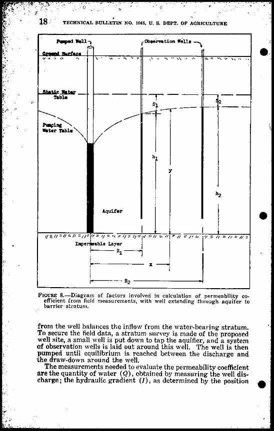
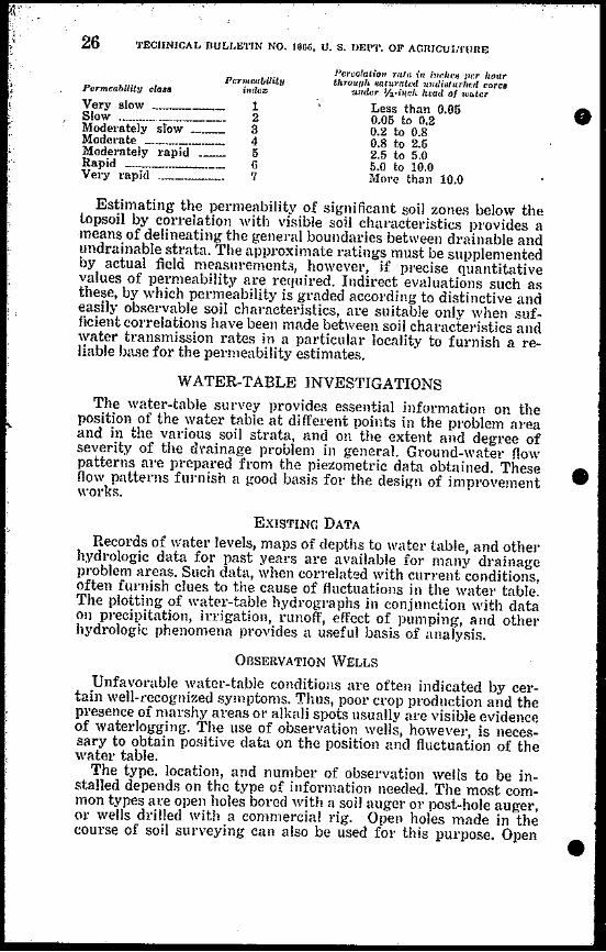

0
OBSERVATION WELL PIEZOMETER WELL DRIVING HAMMER
r- r- ~tQ PIEZOMETERGROUND -tilSURFACE oGROUND SURFACE~ -1 = ~ Z
~~ t ~~ PIPE ci
I I c t_~UND_ _~~E -1__L -~EL t
~--~l- -11111 =tII
Z III
~sectl --+ I III - z ~I 1I11I
e -)--
shy
i -1111 -III ~-111- CA POST B iL PLUG
HOLE til III
rnJ -c- CAVITY FORMED dARROWS INDICATe BY FLUSHING ~It
~
GROUND WATER ENTRANCE -II) LI 34 PIPE
1 THE PIEZOMETER INDICATES THE PRESSURE AT THE POINT OF ENTRANCE RATHER THAN C)LrY o
gt THE LEVEL OF THE GROUND-WATER TABLE
g ~
GRAVEL BACKFILL ALLOWS ENTRANCE THE WELL INDICATES THE LEVEL OF THE OF WATER FROM ANY POINT SURROUNDING GROUND- WATER TABLE
~ ~
~
FIGURE ll-Some details of observation wells and piezometers A Cross-section view of observation well showing proper method of backfill B diagram illustrating fundamental difference in flow of underground water to well and piezometer C detaifs of piezometer driving hammer and method of installation (from Ground-Water Studies in Relation to Drainage by J E Christiansen)
-
_
-j-ibullbull bull bull
29
bull
e
DItAINAGE INVESTIGATION METHODS FOIt IfHUGATED AREAS
DESCRIPTION OF PIEZOMETER The ground-water piezometer consists of a standard 14- or shy
inch iron pipe driven vertically into the ground to a definite level Before driving is started a loose rivet is placed in the lower end of the pipe to keep soil from entering When the desired depth is reached a jointed rod is inserted and the rivet is punched out leaving an open pipe or piezometer In some soils the prptecting rivet is not needed Before driving the exact length of the pipe should be noted so that the elevation of the bottom of the pipe after driving may be determined
The driving is done with a special hammer fashioned like a steel fence-post driver It consists of two pieces of -inch pipe 15 inches and 5 feet long respectively joined by a 1-foot section of 1 lh-inch pipe filled with lead (diagram C of figure 11) This leaded section is fitted with a steel plug at each end to receiye the impact of the blow The top of the piezometer pipe is fitted with a removable -inch driving head The piezometer is started into the ground with the 5-foot end of the hammer over the driving head of the piezometer When the top of the piezometer has been driven to within 5 feet of the ground surface the hammer is inverted and the drivil1g continued until the top of the piezometer is at the desired elevation about 1 foot above the ground Piezometers may be driven with a pneumatic jackhammer if the top of the piezometer pipe is fitted with a driving cap for seating the jackhammer pilot Power driving makes it possible to install piezometers to a depth of 30 feet even in very heavy soils Figure 12 A shows a piezometer being driven with a jackhammer
The deeper the piezometer penetrates the soil the greater will be the friction on the sides Since hand driving of even a 15-foot piezoshymeter in some soils may entail considerable laber the use of this method is definitely limited Placing a joint and coupling about 1 foot from the bottom of the pipe slightly enlarges the hole through which the pipe passes as the piezometer is forced down This helps to reduce side friction and cuts down the resistance to penetration The use of such a coupling permits driving of piezometers by air hammer to depths of approximately 40 feet without causing leakshyage down the sides of the pipe and a resultant los~ of benefit from the piezometric principle Earth from the side walls of the hole closes up the enlarged space surrounding the pipe above thE coupling The 1-foot section of pipe below the coupling is of course ealed at all times against any leakage
Piezometers should be driven as nearly plumb as possible Single lengths up to 14 feet may be installed by working from a stepshyladder For greater depths several sections of pipe are joined with standard pipe couplings the maximum depth of installation being limited only by the difficulty of driving the pipe and removing the rivets
FLUSHING For sllccessful installation and operation of piezometers the
soil at the lower end of the piezometer should be removed by flushshying leaving a small cavity at the bottom of the pipe as shown in diagram C figure 11 Flushing is done by punching the rivet from
bull bull bull
o
tl o z Qgtshyrshycc t t
~ Z z ~
~ S c tl ~ o
gtshyCi ~
(=jc
~ C
FIGURE 12-Driving and jetting piezometers A Driving 14-inch piezometer with an air hammer Tubing in lO-foot lengths may be joined and sunk to a depth of 30 fect by this method fl Jetting] 2-inch piezometcr Coachella Vallc~r Calif
lt
j
bull
gt
J)RAINAGE INVESTIGAflON METHODS FOR IIUUGAtEIgt AUEAS 31
the lower end of the piezometer by punch rods after the pipe has been driven to the desired depth then cleaning out the pipe by pumping water into it through a flexible tube The water escapes by flowing upward through the narrow space between the tubing and the inside wall of the pipe The equipment needed includes a water container stirrup pump and enough plastic tubing l4-inch in outside diameter to reach the bottom of the deepest piezometer used (fig 13) The tubing is marked with colored lacquer at I-foot intervals
rmiddotbull
~
r
~ I
FIGURE 13-Some equipment used in piezometer and well investigationsLeft to 1iuht StilTup pump and plastic tubing for flushing electric watershylevel indicator for piezometer sounding bell for 1-12-inch and larger pipes sounding rods usable also as punch rods for lemoving rivet from piezometer
The plastic tUbing is pushed down inside the pipe during pumpshying until it nears the bottom then gradually lowered until the end is about even with or slightly belOW the end of the piezometer~ Flushing is accelerated by working the tubing up and down care being taken to avoid lowering the tubing beyond the depth specified The water that overflows the pipe is usually very silty at first With continued pumping however the water clears The tubing is then slowly withdrawn while pumping continues
TECHNICAL BULLETIN NO 1065 U S DEPT OF AGRICULTURE
The piezometer is tested for sensitivity by filling the piezometer I~ pipe and observing the rate at which the water drops Experience
will soon indicate the approximate rate to be expected If the rate of drop appears too slow the flushing is repeated the tubing being bulllowered slightly below its previous level to enlarge the cavity In l1ighly permeable sands piezometers take the water so rapidly that no overflow occurs whereas in some soils of low permeability the rate of subsidence of water in the piezometer is hardly perceptible In some instances an equilibrium level is obtained in a few minutes in extreme cases 24 hours or more may be required
In some soils piezameters may be driven to advantage without rivets Although plugs of soil 6 to 8 inches long may pack in the lower end they can be flushed out in less time than would be reshyquired to punch out the rivets
Piezometers may occasionally seal up after being in use for several months Erratic variation in the pressure reading of any piezometer as compared with others in the same vicinity may indishycate sealing which can be readily overcome by reflushing
JETTING PIEZOMETERS
Both piezometers and wells have been installed successfully in certain areas to depths of 100 feet 01 more by jetting (10 11) Figure 12 B illustrates jetting- equipment designed and built for use in connection with cooperatie drainage investigations in Coachella Valley Calif Much greater depths can be attained by jetting than by driving the depth of installation being limited mainly by the size of the aggregate encountered Some highly bull porous formations take the water faster than it can be pumped down and 110 deepening of the jetted hole results
In jetting the soil is removed by flushing it up around the pipe and out of the hole Although this may result in side leakage and cause the pipe to act as a regular well when the well is new the sides seal up after a period of time and the well then functions like a piezometer The difficulty of determining the extent of the seal along the sides of the pipe makes it hard to determine whether the readings obtained are from a well or a piezometer Nevertheless jetting is a quick and easy way to install a deep observation well and the ease and economy of installation far outweigh the limitashytions
REMOVAL OF PIEZOMETERS
Piezometer pipes may be used many times over if care is taken in removing them from the ground Lengths up to 8 feet usually can be pulled by hand after they have been loosened by turning with a pipe wrench For deeper installations the pipes are easily exshytracted by means of a ratchet hoist suspended frol11 an A-frame or tripod of 2- by 4-inch material (fig 1lt1) A set of small metal grippers is fastened to the piezometer and attached to the pull chain of the hoist After removal the pipe should be cleaned of soil and corrosive scale straightened and if non galvanized covered with a light coating of oil to prevent rllsting
The piezometer tube may also be raised with an ordinary soilshy bull
33 DRAINAGE INVESTIGAT()N METHODS FOR JHRiCAlEIJ IEAS
bull
bull
FlGCRf 14-Ratcl1lt hoit tlipod and glippC) used in (gtxtracting d((p pi(Z(lIl1lttI pjPt~
tube jack using a S(lt of sl1lalll1lltal grippers fittcd around the pieshyzometer pipe to provide a btHling sUJfaec fol the jade
MEAseRIXG DE1(ES
There are lJlany differcnt methods of measuring the water elenltion in OIJiienution wells and pieometcls For 11 ~-inch and laJger pipes a sounding b(1 (lig ]3) can be utilized The bell is made by boring out th ((nLer of a l-ineh-c1ial11etel brass rod to a depth of 1 inch until the walls aJe approximMely 1 i32-inch thick A I~-inch shank is formed by turning clown the end of the rod for about l ~ inehes and ~pttilJg a Jin in the end A brass chain about 0inChes 10llg is used to join t11( b(11 to the low-reading end 0pound a metalli( tape Ir it lulJ-lengtJl Lapp is used without foreshortening a correction must )( applied to the watcl-t(ation reading- to COIll shy
bull l1ensate 101 the 1ltIlgth of the sOLinding 1)(11 and ehain As an alternashy
~~
TECHNICAL BULLETIN NO 1066 U S DEPT OF AGRICULTURE34
tive a piece of the tape equal in length to the combined length of bell and chain may be cut off before it is fastened to the chain The tape then gives direct readings The bell is lowered on the end of the tape until the sound of the bell which is clearly audible as much bull as 100 feet from some wells indicates that it has contacted the water surface
A relatively simple adaptation of the sounding bell described above designed to facilitate the reading of open uncased holes made with soil augers has been used successfully in wells of small diameter The bell of this device is made by brazing a large cartshylidge case similar to a 45-70 to a jointed 1b-inch rod The rod is graduated and marked as desired
The depth to water in piezometers and wells may also be sounded by lowering a length of plastic tubing into the pipe while air is being blown into the free end of the tUbing above grutdd When the tubing touches the water an audible vibration is set up in the pipe The water level may be determined either by withdrawing the tubing and measuring the length removed or by using a tube on which unit distances have previously been marked with differently colored lacquers
WATER-LEVEL INDICATOR FOR PIEZOMETERS
The type of sounding device commonly used for larger observashytion wells is unsuited for use with piezometer pipes of small diameter A satisfactory electric water-level indicator has been developed for this purpose (fig 15) The essential parts of the deshyvice are a flexible rubber-covered wire marked with I-foot gradua- bull tions small penlight batteries for current and a milliammeter 01 voltmeter to indicate the closing of the electric circuit
The wire should be highly flexible well insulated and not easily kinked Type FF single-conductor flexible cord is satisfactory
The end of the wire is equipped with a weighted sounder tip made from about eight lengths ofYi-inch brass tubing each section 11 inches long This flexible end permits the plumbing of bent and damaged piezometers The insulated contact wire passes through the series of tubes and is soldered to a metal tip This tip is inshysulated from the brass tubing with a piece of lucite machined to fit into the end of the tubing The wire is marked at I-foot intervals with bands of colored lacquer to indicate successive foot readings It is held on a reel and passes in front of a fixed scale 1 foot long graduated in tenths and hundredths of a foot This scale reads from the top down so that readings are obtained directly to 001 foot A reel harrow enough to accommodate only one width of wire has been found most satisfactory
A milliammeter of 0-25 milliampere range is well adapted as an indicator although a high-resistance voltmeter also gives satisshyfactory results For ground waters that contain a relatively large amount of dissolved salts a single battery cell furnishes sufficient current to give a satisfactory reading for waters with weaker concentration of salts two cells may be required
The instrument is so arranged that when it is seated over the top of the piezometer pipe the readings give the distance from the top bull
GOIITACOT 11124 SKEET R~ I l~~
MILLIAMMETER O-ZS REAORITE D C ADJUSTABLE
IATTEIIY TUIE S O D IY II I D rUle IRASS WIT LUCITE OR EQUAL END FITTINGS LENGrli
A
CENTIIAL STFF 34 O D IY 51 I D TUIE IRS5 LENOT ZO bull
IItMOVLE INNEII SLEEVE 111 o D IY sl I D TUIE IIIASS LENITH 4 lIz
RIGHT
bull REEL Iz4 SHEET IRSS IH DIETER
CONTCT WIRE SINGLE STR ND RUBBER COVERED TINSEL WillE TYPE F f MINIIoIU LEN GTH 20 FT
SCLE BAR lie x Iz BAR BRASS LENGTH IS
WEIGHTED TIP END 14 O D TUiE IRSS INSULTE I SECTIONS I ~2 LONG LENGTIf 12
_SGREW CLA~P 31amp BR~SS
SEATING 78 O D BY 34 I D TUBE BRASS LENGTH s
_SCREW CllMP 316 BRASS
SIDE VIEW
IItEL CIIANII 14)( III IAR iliA
EEL IIIAicE 14 01 X 12 IAR IRASS
i
Y r
IIEEL ANDLE LUCITE 011 EOUAL
B
LEFT SIDE VIEW
gi ~ cl ll
~ ltll g gt
~ liC ll
6 o C rJl
~ ~
~ i gtc ~ rJl
FIGURE I5-Piezometer sounding device ~
~
36 TECHNICAL BULLETIN NO 1065 U S DEPT Ol AGJUCULlURE
of the piezometer to the water surface The weighted wire is unshyreeled into the piezometer until the tip end contacts the water surshyface completing the electric circuit The piezometer itself acts as a part of the circuit one terminal of the dry cell being grounded to bull
I
the instrument which makes contact with the piezometer With care in operation of the device readings accurate to within 001 foot ean be obtained
APPLICATIONS TO GROUND-WATER PROBLEMS
The simplicity ease of installation and accuracy of the piezoshymeter make this instrument a highly effective device for determinshying the height of the ground-water table and its fluctuations When used for this purpose it is installed in single units in a grid pattern over the area to be observed The spacing varies from a 400-foot interval for a 160-acre field to a spacing of VI to I~ mile for a less intensive study covering several square miles The depth of inshystallation is governed by the probable depth of water table at the low ebb of the yearly water-fluctuation cycle and by the existence of unusual stratifications as indicated by borings
Piezometers may also be used to determine the effect of overshyirrigation on the water table in connection with water-use 01 watershyapplication-efficiency studies For this purpose pipes are spaced at frequent intervals along the length of the irrigation run or set of furrows They quickly register any rise in the water table as well as any gradual fall due to subsurface drainage use of water by the crops grown and losses by evaporation Unlike a large-sized well the pipes take up little space and can be installed and removed with a minimum of disturbance to the crOJd
bull
It is important to note that the watel-table levels registered by piezometers are the result of hydrostatic pressure at the bottom end of the pipes It is necessary therefore to ascertain the general stratification of the soil before the piezometers are installed so that they can be terminated in the desired stratunJ GROUND-VATER FLOW PATTERNS-Piezometers may be used to advantage to secure ground-water flow patterns as a means of determining the efficiency of various types of drainage devices in studies of canal seepage and in studies of the source and direction of extraneolls ground-water flow For these purposes piezometers are installed in groups of two or more at each location They are driven to different depths depending on the stratiflc(ltion of the subsoil and the depth of flow pattern desired
A typical example of the manner in which differential-length piezometers may be used in sets to obtain hydrologic data for drainage investigations-specifically to determine whether a canal is leaking-is illustrated in figure 16 In this hypothetical example groups of foul piezometers 5 10 15 and 20 feet in length have been installed on a line perpendicular to the axis of the canal at distances of 15 60 and 100 feet from the center line of the canal (diagram A) Ihe immediate object is to secure hydrostatic pressures at a large number of points under the watm table adjacent to the canal
In diagram TJ which represents the same cross section shown in A the small circles indicate the tel~mination points or the tip ends bull
DRAINAGE INVESTIGATION METII()DS FOR IRRIGATED AREAS 37
ASlU~EO ELEVATION FEET ) A
100 r GOUND SURFACE DAllAL I ~~I I~
l2
SIX IATTEIIES OF OIFfpoundIIENTIAL-LENGTH PIEZOMETERS 8RACMETING AN IRRIGATION CANAL AND TpoundMIIIA1ING AT DpoundPTHS OF 5 1015 AND 20 FEET
e 100
ll0 0 )]rtre21 09591 950e 0
shy 0 0 2 0 o 9750 o 91~O 95000
0 Q U_ 0 09572 o 9575 9450
bull tQ0 0 0 020 o 9550 4700
THE ~EFT SIDE IS iLOTTEOTO SIIOW THE PIEZOMETER TERMINATION ~EVE~S THE PlIES SUMS IN THE PIEZOMETERS AAE MEASURED AT THESE POINTS
THpound AIGHT SIDE GIVES THE WATEA E~EVATION IN THE PIEZOMETER TuaES THESE ELEVATIONS ARE PLOTTED AT THE PIEZOMETER TERMINATION POINTS
bull C
TA8~pound i C ~ Ei 7- -WATER _ - - _ ~= I - -_
0 011 ge21 --OJ J ~
~ ~ ~~ -------shy0500 ~ IS 0 bull 0 ~~-~~5C P o 09672 0)1 0010 T~ -V415
0
OJ
09470 09550 0 H20 0 0 THE LEFT SIDE SHOWS LINES OF EOUAL PRESSURE PARTL~ ORAWII LIliES OF EQUAL PRESSUIIE AE DIIAWN SIMILAR TO GROUND-SURFACE COHTOURs
THE RIGMT SIDE SHOWS THE FINISHED LINpoundS OF EQUAL PESsUR AND Til AOWS INDICATE THE OIlIlCTION Of GOUIID-WATER MOVEMENT
100 to 10 40 t o to 40 10 10 100 I
DISTANCE FRON CANAL (poundpoundT)
FIGURE I6-Plotting differential-length piezometer data in t~edeterminatjon of equipotential pressure lines
38 JECIINICAL BULLEfIN NO 1060 U S DEPl OF AGRICULTURE
of each piez0i11eter The numerical designation beside each circle is the water-level elevation in each piezometer Thus the 5-foot piezometer located 15 feet to the right of the canal has a water level bull of 9821 feet above zero datum (179 feet below ground-surface datum of 100) In similar manner the 10-foot piezometer at the same spot has a water-level elevation of 9750 and the 15-foot piezoshymeter a water-level elevation of 9672 lhese elevations are a direct reflection of the hydrostatic pressure at the respective points in the soil and provide in effect a water-level profile of the area adjacent to the canal
The third step is to draw contoulS of equal hydrostatic presslles (equipotential lines) as in diagram C These pressure lines are drawn in the vertical plane in much the same manner as groundshysmface contour lines are drawn in the horizontal plane The conshytour lines provide a pattern of the hydrostatic pressure potential for the soil profile about the canal and indicate the direction of water movement through the soil The charting of the various paths of movement called stream lines of flow is based on thei principle that water in the soil moves from points of high hydroshystatic pressure to points of low hydrostatic pressure in a path of underground flow that is always at right angles to the contour line of equal pressure For example a particle of water in the soil at the 980 pressure line will move towards the 975 pressure Iinc
The following rules arc helpful in plotting- piezometer data 1 Equipotential lines must interRect the frce water surface at
right angles and at equal increments of elevation 2 The head loss between adjacent equipotential lines must be bull
constant 3 The quantity of seepage flow between adjacent flow lines iR
constant bull1 The canal bottom and canal sides compriRc the upper equishy
potential line 5 The static water table is the 10 vest equipotential line 6 The water surface is the long-est flow line 7 The vertical line of flow along the center line of the canal if
the shortest flow line Stream lines of flow can be charted to show the dile(tion of
water movement toward drains tile lines Sllmps wells canals springs or any spot for which information on ground-water moveshyment is needed A knowledge of the orig-in of the excess water and its direction of movement makes pORsible the deRign of a drainage svstem which will either intercept the flow of water or check it at the SOllrce Ground-water information al~o aids in determining whether draillage devices already installed are functioning propshyerly and provides clues to the betterment of existing designs of improvement works and the development of new ones
WATER-SOURCE SURVEY
The water-source survey provides a ]ey to the measures needed to remedy undesirable drainage conditions More specifically the water SOUlce often governs the type of drainage to be installed Thus if excess water is due to precipitation the remedial measure bull
Ii
DRAINAGE INVESTIGATION METHODS FOR IRItIGATED AREAS 39
would probably be better surface drainage if due to canal seepage an interception drain may be indicated and if due to artesian presshysUle elief wells may provide the most practicable remedy In some poblem aleas the source of water is obvious In otherll iIishycluding many westelll valleys the sources of water may be both numerous and complex making specific origins difficult to discern A consideration of all the pertinent information on geology topshyography soil strata and water table mentioned in previous secshytions is needed to detelmine the source of the water
SOURCES OF WATER
The common sources of water of major importance in drainage problems in irrigated areas are precipitation irrigation seepage and hydrostatic pressure manifested in various forms
PRECIPITATION
Precipitation records should be gathered and analyzed for the area under investigation in order to determine both the monthly distribution and the long-term cyclic trend of preCilJitation
A positive correlation between the distribution of precipitation during the year and the fluctuations in vater-table elevations may be evidence that seasonal precipitation is one of the chief SOUlces of water Lack of such cOlrelation indicates that precipitation probably has little effect on the water table
bull An attempt should be made to determine whether long-term
cycles of precipitation are related to long-term hydrographs of water levels for example whether wet cycles are followed by risshying water tables and vice versa Deep seepage to artesian or other aquifers though slow may often be manifested by a rise in water levelS sometimes years after the peak of a precipitation cycle has passed In some areas changes in ground-water levels may be more closely associated with the snowfall in adjacent or distmlt mountain areas and with the period and rate of snow melt than with rajnfall
Precipitation affects artesian wells deep static wells and shalshylow piezometer wells differently The lesponse of water surface levels in these wells provides indications of the degree mode and duration of influence of precipitation on the water table
IRRIGATION
Many drainage problems in irrigated areas are traceable to faulty irrigittion practices particularly the application of too much irrigation water In order to determine the extent to which irrigashytion practices contribute to such problems studies should be made of (1) the effect on the water table of single irrigations (2) water-table fluctuations throughout the irrigation season and (3) long-time changes in water-table elevation over a period of years subsequent to the beginning of irrigatioil
Poor methods of water application and inefficient use of irrigashytion water are likely to result in the loss of large amounts of water by deep percolation and surface runoff Methods of applying water
vary widely depending on such factors as soil slope crops size of
40
l]CHNICAL BULLETIN NO 1066 U S DEPT Ol~ AGlUCULlURE
field delivery schedule of water and availability of water Irrigashytion practices should be related to crop needs and soil properties Only the amounts of water needed for the crops and to maintain a suitable salt balance should be applied Efficient water management reduces the need for drainage in irrigated areas
Perched water tables caused by the accumulation of excess amounts of irrigation water over impervious layers in the sol1 profile are common in many irrigated areas Since it is extremely difficult to apply exactly enough water the tendency is to put more water on the land than is actually needed The surplus must be disposed of in some manner The adequaey of waste ways outlets to natural 01 man-made open drains and other disposal facilities should be carefully determined and the possibilities for improveshyment thoroughly explored
SEEPAGE
Seepage a major source of wateL in many drainage problem areas likewise requires careful field study Man-macle seepage u~ually stems from poorly comtructecl OJ improperly located illigashytion works such as Cal1ltt1s reservoirs and other conveyance and impounding structures Seepage from these sources may be deshytected by methodil predously described A comparison of fluctuashytions of water level in the ground with those of water levels in adjacent canals 01 resenoils indicates whether water is seeping from these structures into the underground water table Evidence of subsurface seepage is often prodded by the presence of tules willows and other n1ter-loing plants Under certain conditions seepage may also be detected by introducing dyes 01 concenb-ated saline solutions at or neal the suspected source of seepage and notshying their movement and point of emergence (13)
HYDROSTATIC PRESSURES
Underground aquifers under l1ydrostatic pressure may be a directcontributory source of water in a drainage problem area Impermeable geologic straUl that overlie such aquifers impede the free vertical flow of water but the drilling of wells through the confining strata releases the pressure and forces the water to the surface as flowing artesian wells It is important to identify the aquifer stratum yielding the (Jo in order that the artesian presshysure may be traced to its source Examination of well logs often provides the clue to the location of the aquifer under pressure Other clues are given by the pressure differential in wells of difshyferent depths and by the period of peak pressure and the quality of water in different wells
For example it is not uncommon in artesian pressure areas for several aquifer zones to be separated by layers of shale or heavy clay By measuring the pressures in wells that tap different conshyfined strata the relative significance of each stratum can be deshytermined Where the pressure and consequent flow from wells fluctuate a comparison of the cycle of fluctuation with other hydroshylogic pl1enomena may furnish a clue to the source of artesian water Thus in mountain valleys a decline of artesian pressures following
bull
bull
bull
41 DRAINAGE INVESTIGATIONlIfETHODS FOR IRRIGATED AREAS
legularly upon the termination of spring snow melt furnishes good evidence that the artesian flow has its source in the mountain snow packs The dwindling runoff is insufficient to recharge the watershybearing strata and maintain the hydrostatic pressure
The quality of water in artesian wells probably furnishes the most reliable clue to the location of the source A relatively pure water free of saline elements suggests that the source is either runoff from precipitation 01 some deep-level lecharge from surshyrounding watershed areas Water high in calcium carbonate conshytent suggests a limestone-aquifer source Certain contaminating saline elements are traceable for many miles Boron and other minerals in fact are often used to classify and identify artesian zones and sources of pressure LEAKAGE FROM WELLs-In the irrigated areas of many western valleys it is not uncommon to find wells 50 years old which had been drilled for domestic or irligation use Such wells especially the artesian are often a source of seepage into surrounding lands They also serve as conduits for the flow of water from one stratum to another as the casings rust out Lealwge llOt only causes an apshypreciable loss of water in the well but may aiso cause waterlogging of adjacent soil
bull
Leakage in artesian wells may be detected in various ways (8)The most common method is to lower a specially devised current meter into the well and record the fiow at various depths A flow greater at any level than at the top is positive proof of leakage some place along the well casing Careful current-meter readings taken at 5-foot intervals will locate the approximate points of inshyflow and otJtflow of artesian water
Semialtesian wells-those 1n which the artesian pressure is too slight to enable the flow to rise to the ground surface-may leak entirely below the ground surface Such wells are usually charshyacterized by a water level higher than that of the shallow water table in the surrounding area The leakage is difficult to detect because the movement of water is generally too slow to be measshyured by current meters
A method involving the introduction of a salt brine into the well has been used successfully to detect the direction but not the quantity of water movement The well being investigated is logged electrically by lowering a two-wire electrode into the water and taking conductance readings at successive 5-foot intervals Plastic tubing 11 inch in diameter is then lowered into the well a distance of about 50 feet (in a 75-foot well) and 2 gallons of salt brine are pumped into the well This brine contaminates about a 6-foot zone of water in the well and can be accurately located with the conshyductance electrode wire Being heavier than fresh water it difshyfuses downward in a nonleaking or nonartesian wen In a semi artesian well with upward flow it diffuses upward and may be detected at successively higher points in the well by means of the electrodes This upward movement can be charted by logging the well at about half-hour intervals SPRINGS AND SEEPS-Two types of springs or seeps should be distinguished-those originating at the base of steep slopes where the topography breaks abruptly and those caused by faultshy
I
42 TECHNICAL BULLETIN NO lOGo Ubullbull S DEPl OF AGRICULTURE
ing The first type which is usually found along the edges of a valley is characterized by perennial flow and fresh cold water The second is caused by the fracture or displacement of confining clay or rock layers above an artesian aquifer thus forcing the water in bull
I the artesian zone to the surface A line of such springs may deshylineate a fault line Springs of this type are often thermal and may contain excessive amounts of minerals or mineralized compounds According to an old rule of thumb the depth of source of water feeding a spling can be estimated by the temperature of the water ie the hotter the water the deeper is the source Ordinarily the deep-seated fault springs are warm whereas the shallow springs originating as bedrock outcrop seepage are cold
SALINITY OF WATER
A knowledge of the salinity of the ground water in a particular drainage problem area is important because of the adverse effect
of saline water on the growth and production of crop plants In areas of nonsaline soil water the solution to the drainage problem is largely a matter of merely lowering the water table to a point far enough below the root zone of the plants to keep excess water from interfering with normal plant-growth processes Some latishytude in the fluctuation of the water-table elevations is permissible
In areas of saline ground water however the water table must not only be lowered to a point well below the feeding zone of the plant roots but must also be kept from rising above that level so that evaporation and capillary forces will not concentrate the salts in the root zone rhe presence of large amounts of harmful mineral elements in the root zone of the soil intensifies the drainage problem since steps must then be taken to drain not only the excess water bull initially present but also any additional quantities that must be applied to leach the salts out of the soil The danger of losing esshysential plant nutrients in the leaching process further complicates the problem of devising effective drainage systems and measures
The scope of this bulletin does not permit a detailed treatment of salinity-investigation procedures which is a specialized field of its own It is desired to point out however that salinity investishygations including tests to determine the character and amount of mineral elements in the soil and water are needed for the developshyment of sound solutions to the drainage problems in saline areas
TYPES OF DRAINAGE SYSTEMS AND STRUCTURES
The type of drainage needed in a particular drainage problem area will depend in large measure on the facts revealed by the topographic soil water-table and rater-source surveys outlined in the preceding pages As brought out in the section entitled Basic Drainage Il1formatioll the development of suitable remedies f01 J
undesirable conditions should be undertaken only after a thorough analysis and evaluation of all the physical factors involved Some of the limitations and possibilities of various types of drainage systems in current use together with examples of conditions under which they may be expected to function satisfactorily were preshysented in that earlier section bull
I
43
Ii l 1 - --
I
DRAINAGE INVESTIGATION METHODS 1OR IRRIGATED AREAS
It is important to note as a final consideration that methods of drainage investigation for a particular area or for a particular problem should be selected with aue regard for the prastical aspects of drainage works including design and construction requireshyments and the practical limitations of operation and use of the different types of drainage structures In this connection three broad types of drainage structures may be distinguished-Open drains covered drains and sumps and wells The following brief description of commonly used drainage works covers some of the more important features of drainage structures with which pershysons engaged in drainage investigations should become familiar It is not a guide to farm-drainage construction a subject treated more fully in current bulletins published by State and Federal agencies and industrial concerns alld in standard reference works on the subject
OPEN DRAINS
Open drains may be either shallow 01 deep each type having its specific use in drainage
bull
Shallow open drains are used primarily to remove excess vater from the stuface of the field They range in depth from 2 to 4 feet and may have cross sections of various shapes depending on the soil depth of drain and location in the field In areas where it is advantageous to remove winter precipitation and dry the surface soil for early spring planting shallow drains are placed parallel to the direction of irrigation Shallow drains are usually built with broad gently sloping sides that can be crossed with planting tillage and harvesting machines In areas where the application of irrigation water is difficult to control waste ditches are necesshysary at the lower ends of the fields Shallow drains for this purpose are generally built with steep side slopes Channel grades should be kept to nonerodible slopes Outlet structures should always be proshyvided at points where shallow drains must empty into deeper drains in an abrupt drop
Deep open drains are used to transport excess water to a lake river or other outlet 01 to remove underground water from adjacent areas They also serve as outlets for shallow surface waste drains In general the bottom width is not less than 3 to 4 feet to provide for easy cleaning with machines The sides are sloped at an angle corresponding to the 110rmal angJe of repose of the natural soil material to prevent bank caving and resultant blocking of the drain In the lighter sandy soils side slopes as gentle as 3 to 1 may be required whereas in certain heavy clay soils side slopes of 1 to 1 are permissible The channel grades vary with soil conditions The optimum grade is a function of the velocity of water moveshyment in the drain Although a velocity in the range of 212 to 4 feet per second tends to erode the bottom drains designed for velocities within that range in most soils usually stabilize themselves and become more 01 less self-cleaning
Deep open drains range in depth from 4 to 20 feet or more the
bull actual depth being governed by soil topography depth of lead-in drains and related conditions In flat lacustrine valleys depth is
44 TECHNICAL BULLETIN NO 1065 U S DEPT OF AGRICULTURE
generally controlled by outlet depth in mountain areas of rough topography by the stratification of the soils In order to secure optimum underdrainage the deep drain should cut vertically across the more permeable strata thus tapping the water-bearing layers ofthe soil and letting the excess water flow into the drain
COVERED DRAINS
Covered drains include various kinds of manufactured conduits such as concrete tile clay tile and fiber pipe also brush-filled and gravel-filled ditches The covered drain almost universally used in westelll United States is the concrete 01 clay tile All covered conshyduit drains are constructed by laying the conduit in a vertical-sided trench and completely backfilling the trench Covered drains vary in depth but for effective drainage in irrigated areas the bottom of the drain should be not less than i1 ~~ feet below the ground surshyface Covered drains require a suitable outlet into which the water carried by them may discharge The outlet is generally an open drain but a sump may also be used Vater that has drained to a sump is disposed of by pumping into surface asteways
Tile lines by far the most common kind of covered drain are of two main types-relief systems and interceptor lines Relief systems consist of a series of lateral tile lines laid out in a grid 01 herringbone pattern each line being connected to a main trunk which in turn outlets into an open drain An interceptor tile line is a single line installed along the base of a hill parallel to a leakshying canal or around a leaking reservoir It intercepts groundshywater flow at an advantageous point and prevents movement of water into the drainage-problem area
The depth of tile lines is dependent upon outlet depth general topography of the ground surface and the position of the atershybearing strata in the soil profile Since the primary function of the tile line is the removal of underground water the tiles should preferabljr be placed in the more pervious soil strata This assures easy access of the water to the conyeyor line and provides wide lateral drainage
Tile systems must be instalJed in rigid conformance with deshysigned slopes and alinement The minimum grade for a tile line is 1 foot of fall per thousand feet of line Steeper grades are desirable The steeper the grade the less likelihood there will be that silt wiII clog the line and the less exacting will be the control of grade required during trench construction
WELLS AND SUMPS
Drainage wells vary in depth size and capacity according to the nature of the drainage problem involved When installed as a part of the irrigation system they may be utilized as a water supply for the area bping drained In artesian areas they may be installed in or along the side of deep open drains to capture excess artesian water that Hows to the surface This helps to relieve pressure on the aquifer and results in the lowering of the watel level
The depth of the well its capacity and the effective radius of drainage depend in part upon the geologic strati fication of the area
bull
bull
bull
45 DRAINAGE INVESTIGAlION METHODS FOR IRRIGATED ARElAS
bull The water collected in drainage wells may be disposed of by
pumping into open drains Pumping for drainage alone however is liable to be expensive especially where an extensive area is inshyvolved because the amount of water that must be pumped to produce a significant drop in the water level at a remote distance from a wen is relatively large For drainage wells to be ecoshynomically feasible therefore some provision should be made to make productive use of the water pumped
Sumps are lalge shallow holes generally 110t over 20 feet in depth into which water seeps from the surrounding soil They are used primarily to dispose of exces water from small watershylogged areas or l)oclets Because of their shallow depth their efshyfective radius is small They may also be used as outlets for tile lines
LITERATURE CITED (1) CHRISTIANSEN J K
19middot13 GROUND WATER liTUDIES IN RELATION 10 OIlArNAGE Agl Engin N339-3J2
(2) DONNAN W W AND CHHlSTIANSEN J E 1944 P1EZOllBTERS FOR GROUND-WAlER INVESTlGAlION West
Construct Ncws 19 77-79 illus (3) DONNAN W W ARONOVICI V S AND Fox IY W
19middot14 TIlE 1lIPEllfAL VAlrEY SOfL SAlIILTNG DEVICE Soil Sci Soc A mer Proc 8 367-371
bull (4) DONNAN W
H)46 STREAIIlINE FlOW Iowa Engin 46 126-130 illus (5) FmJVERT R K AND KmKHAlI DON
1918 A FJELD IETHOD FOR nASlmiddotIUNG TilE PEHlIIEABIlITY OF SOTT B~JroW A WATER lAllIE Highway Res Bd PJoc 28 433-442
(6) I-IAIlDING S W AND WOOO 1 K 1942 IIOIJEI TESTS OF FLOW INTO DRAINS Soil Sci Soc Amcr Proc
6117-119 (7) KmIGfAlJ DON
1940 PRE)SL1lE AXD STREA~llIXr~DlSTlnBUTJON IN WAnnrOGGED LAND OVEHJYING AN IMIERVIOLS IAYER Soil Sci Soc AllieI PImiddotoe 5 i5-(jS illus
(8) MEINZER O E 1927 IE1HODS OF EXPLORING AND REPAIRING LEAKY ARTESIAN WEILS
U S Geo SUlve~ Water-Supply Paper 596-A illus (l) uIUSKAT M
1937 FlOW OF HOMOGENEOUS FIUlOS THHOUGH POROUS ~IEDA McGraw-Hill Book Co New York
(10) PULSBUltY A F AND CHRISTIANS~N LE 1947 INSTALLING GROUND WATER PIEZOlIET~RS BY JETTING FOn
DRAINAGE INVESTIGATIONS Agli Engin 28 409-410 (11) REGER J S PrrLSUUHY A F REEVE R C JND PETERSUN R K
1950 TECHNIQUES FOR DRAIN Am) INVESTIGATIONS IN COAClIEL1A VALshyUY CAfIFORNIA Agr Engin a 159-564
(12) UHLAND R E AND ONEAl A 111 1951 SOIT PERIEABHITY DETERlIIINTIONS FOR USE IN SOil AND WATER
CONSERVArION U S Soil Conserv Servo TP-l01 36pp mus
(13) WENSEL L K 1N2 JIIETHODS FOR DETERMINING PERlIIEAllllITY OF WATER-IlEARING
lIIATERIAlS US Ceo Survey Water-Supply Papetmiddot 887
bull 192 pp iJlus
J u S GOVERNMENT PRfNrJNG OFFICE 19S3~2t3447
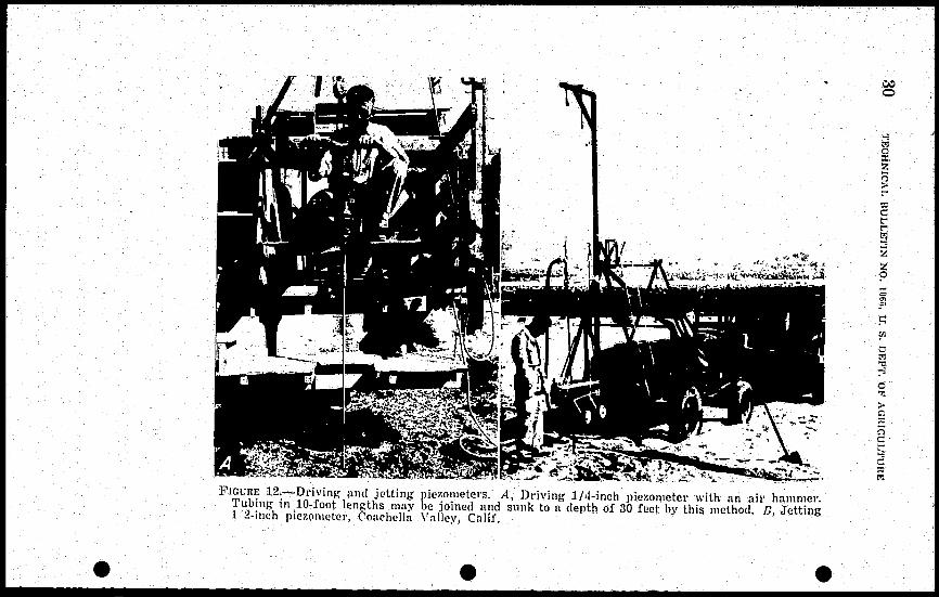
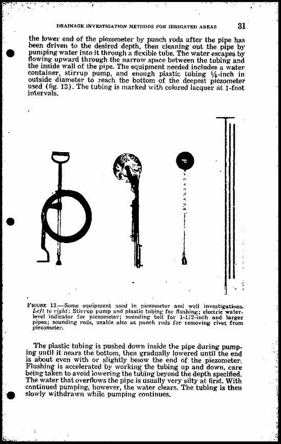
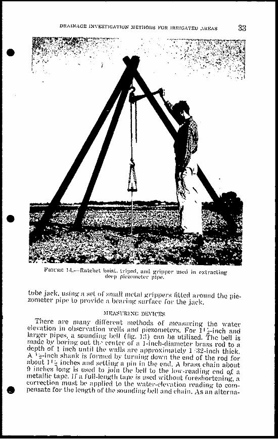
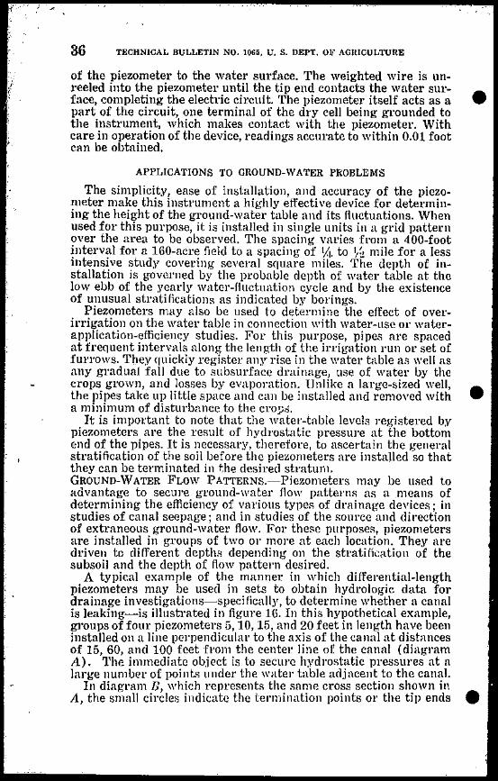
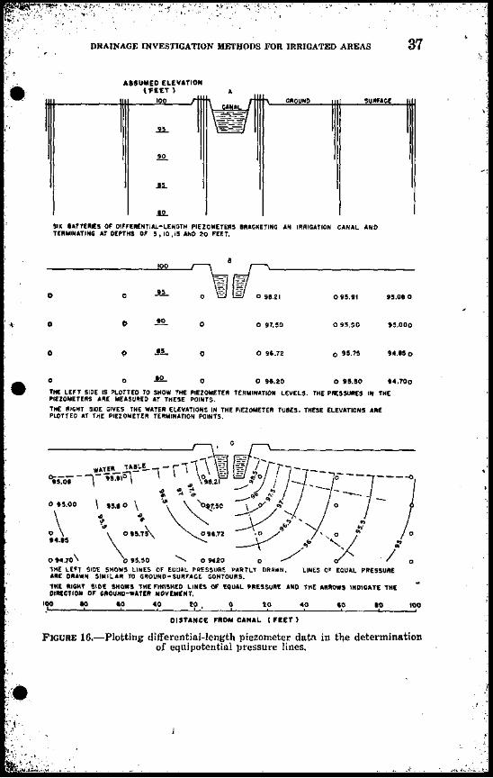

I
42 TECHNICAL BULLETIN NO lOGo Ubullbull S DEPl OF AGRICULTURE
ing The first type which is usually found along the edges of a valley is characterized by perennial flow and fresh cold water The second is caused by the fracture or displacement of confining clay or rock layers above an artesian aquifer thus forcing the water in bull
I the artesian zone to the surface A line of such springs may deshylineate a fault line Springs of this type are often thermal and may contain excessive amounts of minerals or mineralized compounds According to an old rule of thumb the depth of source of water feeding a spling can be estimated by the temperature of the water ie the hotter the water the deeper is the source Ordinarily the deep-seated fault springs are warm whereas the shallow springs originating as bedrock outcrop seepage are cold
SALINITY OF WATER
A knowledge of the salinity of the ground water in a particular drainage problem area is important because of the adverse effect
of saline water on the growth and production of crop plants In areas of nonsaline soil water the solution to the drainage problem is largely a matter of merely lowering the water table to a point far enough below the root zone of the plants to keep excess water from interfering with normal plant-growth processes Some latishytude in the fluctuation of the water-table elevations is permissible
In areas of saline ground water however the water table must not only be lowered to a point well below the feeding zone of the plant roots but must also be kept from rising above that level so that evaporation and capillary forces will not concentrate the salts in the root zone rhe presence of large amounts of harmful mineral elements in the root zone of the soil intensifies the drainage problem since steps must then be taken to drain not only the excess water bull initially present but also any additional quantities that must be applied to leach the salts out of the soil The danger of losing esshysential plant nutrients in the leaching process further complicates the problem of devising effective drainage systems and measures
The scope of this bulletin does not permit a detailed treatment of salinity-investigation procedures which is a specialized field of its own It is desired to point out however that salinity investishygations including tests to determine the character and amount of mineral elements in the soil and water are needed for the developshyment of sound solutions to the drainage problems in saline areas
TYPES OF DRAINAGE SYSTEMS AND STRUCTURES
The type of drainage needed in a particular drainage problem area will depend in large measure on the facts revealed by the topographic soil water-table and rater-source surveys outlined in the preceding pages As brought out in the section entitled Basic Drainage Il1formatioll the development of suitable remedies f01 J
undesirable conditions should be undertaken only after a thorough analysis and evaluation of all the physical factors involved Some of the limitations and possibilities of various types of drainage systems in current use together with examples of conditions under which they may be expected to function satisfactorily were preshysented in that earlier section bull
I
43
Ii l 1 - --
I
DRAINAGE INVESTIGATION METHODS 1OR IRRIGATED AREAS
It is important to note as a final consideration that methods of drainage investigation for a particular area or for a particular problem should be selected with aue regard for the prastical aspects of drainage works including design and construction requireshyments and the practical limitations of operation and use of the different types of drainage structures In this connection three broad types of drainage structures may be distinguished-Open drains covered drains and sumps and wells The following brief description of commonly used drainage works covers some of the more important features of drainage structures with which pershysons engaged in drainage investigations should become familiar It is not a guide to farm-drainage construction a subject treated more fully in current bulletins published by State and Federal agencies and industrial concerns alld in standard reference works on the subject
OPEN DRAINS
Open drains may be either shallow 01 deep each type having its specific use in drainage
bull
Shallow open drains are used primarily to remove excess vater from the stuface of the field They range in depth from 2 to 4 feet and may have cross sections of various shapes depending on the soil depth of drain and location in the field In areas where it is advantageous to remove winter precipitation and dry the surface soil for early spring planting shallow drains are placed parallel to the direction of irrigation Shallow drains are usually built with broad gently sloping sides that can be crossed with planting tillage and harvesting machines In areas where the application of irrigation water is difficult to control waste ditches are necesshysary at the lower ends of the fields Shallow drains for this purpose are generally built with steep side slopes Channel grades should be kept to nonerodible slopes Outlet structures should always be proshyvided at points where shallow drains must empty into deeper drains in an abrupt drop
Deep open drains are used to transport excess water to a lake river or other outlet 01 to remove underground water from adjacent areas They also serve as outlets for shallow surface waste drains In general the bottom width is not less than 3 to 4 feet to provide for easy cleaning with machines The sides are sloped at an angle corresponding to the 110rmal angJe of repose of the natural soil material to prevent bank caving and resultant blocking of the drain In the lighter sandy soils side slopes as gentle as 3 to 1 may be required whereas in certain heavy clay soils side slopes of 1 to 1 are permissible The channel grades vary with soil conditions The optimum grade is a function of the velocity of water moveshyment in the drain Although a velocity in the range of 212 to 4 feet per second tends to erode the bottom drains designed for velocities within that range in most soils usually stabilize themselves and become more 01 less self-cleaning
Deep open drains range in depth from 4 to 20 feet or more the
bull actual depth being governed by soil topography depth of lead-in drains and related conditions In flat lacustrine valleys depth is
44 TECHNICAL BULLETIN NO 1065 U S DEPT OF AGRICULTURE
generally controlled by outlet depth in mountain areas of rough topography by the stratification of the soils In order to secure optimum underdrainage the deep drain should cut vertically across the more permeable strata thus tapping the water-bearing layers ofthe soil and letting the excess water flow into the drain
COVERED DRAINS
Covered drains include various kinds of manufactured conduits such as concrete tile clay tile and fiber pipe also brush-filled and gravel-filled ditches The covered drain almost universally used in westelll United States is the concrete 01 clay tile All covered conshyduit drains are constructed by laying the conduit in a vertical-sided trench and completely backfilling the trench Covered drains vary in depth but for effective drainage in irrigated areas the bottom of the drain should be not less than i1 ~~ feet below the ground surshyface Covered drains require a suitable outlet into which the water carried by them may discharge The outlet is generally an open drain but a sump may also be used Vater that has drained to a sump is disposed of by pumping into surface asteways
Tile lines by far the most common kind of covered drain are of two main types-relief systems and interceptor lines Relief systems consist of a series of lateral tile lines laid out in a grid 01 herringbone pattern each line being connected to a main trunk which in turn outlets into an open drain An interceptor tile line is a single line installed along the base of a hill parallel to a leakshying canal or around a leaking reservoir It intercepts groundshywater flow at an advantageous point and prevents movement of water into the drainage-problem area
The depth of tile lines is dependent upon outlet depth general topography of the ground surface and the position of the atershybearing strata in the soil profile Since the primary function of the tile line is the removal of underground water the tiles should preferabljr be placed in the more pervious soil strata This assures easy access of the water to the conyeyor line and provides wide lateral drainage
Tile systems must be instalJed in rigid conformance with deshysigned slopes and alinement The minimum grade for a tile line is 1 foot of fall per thousand feet of line Steeper grades are desirable The steeper the grade the less likelihood there will be that silt wiII clog the line and the less exacting will be the control of grade required during trench construction
WELLS AND SUMPS
Drainage wells vary in depth size and capacity according to the nature of the drainage problem involved When installed as a part of the irrigation system they may be utilized as a water supply for the area bping drained In artesian areas they may be installed in or along the side of deep open drains to capture excess artesian water that Hows to the surface This helps to relieve pressure on the aquifer and results in the lowering of the watel level
The depth of the well its capacity and the effective radius of drainage depend in part upon the geologic strati fication of the area
bull
bull
bull
45 DRAINAGE INVESTIGAlION METHODS FOR IRRIGATED ARElAS
bull The water collected in drainage wells may be disposed of by
pumping into open drains Pumping for drainage alone however is liable to be expensive especially where an extensive area is inshyvolved because the amount of water that must be pumped to produce a significant drop in the water level at a remote distance from a wen is relatively large For drainage wells to be ecoshynomically feasible therefore some provision should be made to make productive use of the water pumped
Sumps are lalge shallow holes generally 110t over 20 feet in depth into which water seeps from the surrounding soil They are used primarily to dispose of exces water from small watershylogged areas or l)oclets Because of their shallow depth their efshyfective radius is small They may also be used as outlets for tile lines
LITERATURE CITED (1) CHRISTIANSEN J K
19middot13 GROUND WATER liTUDIES IN RELATION 10 OIlArNAGE Agl Engin N339-3J2
(2) DONNAN W W AND CHHlSTIANSEN J E 1944 P1EZOllBTERS FOR GROUND-WAlER INVESTlGAlION West
Construct Ncws 19 77-79 illus (3) DONNAN W W ARONOVICI V S AND Fox IY W
19middot14 TIlE 1lIPEllfAL VAlrEY SOfL SAlIILTNG DEVICE Soil Sci Soc A mer Proc 8 367-371
bull (4) DONNAN W
H)46 STREAIIlINE FlOW Iowa Engin 46 126-130 illus (5) FmJVERT R K AND KmKHAlI DON
1918 A FJELD IETHOD FOR nASlmiddotIUNG TilE PEHlIIEABIlITY OF SOTT B~JroW A WATER lAllIE Highway Res Bd PJoc 28 433-442
(6) I-IAIlDING S W AND WOOO 1 K 1942 IIOIJEI TESTS OF FLOW INTO DRAINS Soil Sci Soc Amcr Proc
6117-119 (7) KmIGfAlJ DON
1940 PRE)SL1lE AXD STREA~llIXr~DlSTlnBUTJON IN WAnnrOGGED LAND OVEHJYING AN IMIERVIOLS IAYER Soil Sci Soc AllieI PImiddotoe 5 i5-(jS illus
(8) MEINZER O E 1927 IE1HODS OF EXPLORING AND REPAIRING LEAKY ARTESIAN WEILS
U S Geo SUlve~ Water-Supply Paper 596-A illus (l) uIUSKAT M
1937 FlOW OF HOMOGENEOUS FIUlOS THHOUGH POROUS ~IEDA McGraw-Hill Book Co New York
(10) PULSBUltY A F AND CHRISTIANS~N LE 1947 INSTALLING GROUND WATER PIEZOlIET~RS BY JETTING FOn
DRAINAGE INVESTIGATIONS Agli Engin 28 409-410 (11) REGER J S PrrLSUUHY A F REEVE R C JND PETERSUN R K
1950 TECHNIQUES FOR DRAIN Am) INVESTIGATIONS IN COAClIEL1A VALshyUY CAfIFORNIA Agr Engin a 159-564
(12) UHLAND R E AND ONEAl A 111 1951 SOIT PERIEABHITY DETERlIIINTIONS FOR USE IN SOil AND WATER
CONSERVArION U S Soil Conserv Servo TP-l01 36pp mus
(13) WENSEL L K 1N2 JIIETHODS FOR DETERMINING PERlIIEAllllITY OF WATER-IlEARING
lIIATERIAlS US Ceo Survey Water-Supply Papetmiddot 887
bull 192 pp iJlus
J u S GOVERNMENT PRfNrJNG OFFICE 19S3~2t3447


