159
DRESDEN STATION, UNIT 2 SPECIAL REPORT NO. 28 ANALYSES AND PROCEDURES FOH HANDLING GENERAL ELECTRIC IF-300 SPENT FUEL SHIPPING CASK MAY 1973 stJ -e.25 7 "'J06 /, J lf 3610

-~
DRESDEN STATION, UNIT 2
SPECIAL REPORT NO. 28
ANALYSES AND PROCEDURES FOH HANDLING
GENERAL ELECTRIC IF-300
SPENT FUEL SHIPPING CASK
MAY 1973
stJ -e.25 7
"'J06 /, J lf 3610

Abstract
The analyses presented in the Quad-Cities Dockets (50-254 and 50-265) for use of the hypothetical 100-ton fuel cask have been supplemented by calculations for General Electric's IF-300 70-ton cask, using current ACI 318-71 Standards (ratified February 9, 1971). The lF-300 will be the specific equipment to be used at Dresden Station during the summer and fall of 1973 to .remove the core of fuel stored in Unit 2 1 s spent fuel storage pool. The lighter weight of this particular fuel shipment cask mitigates the consequences of a postulated cask-drop accident.
Addendum A hereto, page 5, concludes that the conservative Load Factor against any cracking of the fuel pool floor subsequent to a postulated vertical cask-drop is 1.44, a 44% safety margin. Likewise, on page 9, the Load Factor against any cracking S"t+bsequent to a "worst-case" horizontal drop is 2.00, a 100% safety margin.
It is therefo~e concluded that non-neflible cracking of the fuel pool will not occur in the case of F-300 cask-drop.
-1-. :.:-, . ~' ; -- ~

Documentation
The conclusion we have drawn is predicated upon the use of the IF-300, which will have been (prior to its use at Dresden Station) evaluated and licensed in accordance with the regulatory requirements and special conditions of use specified by AEC and the u.s. Department of Transportation (DOT). Addendum B hereto describes the IF-300 Irradiated Fuel Shipping Cask.
We will draw upon the experience and expertise of the IF-300 owners to provide detaile.d handling criteria applicable to the safe use of their fuel cask. Addendum C hereto describes the Operating Instructions for G.E.'s IF-300 Irradiated Fuel Shipping Container and.Transport System.
Likewise the Dresden Station administrative controls and procedures shall be relied upon to provide credible boundaries upon possible accident conditions. Addendum D hereto describes the Dresden Station Cask Handling Procedure• Detailed technical support for the aforementioned procedures is contained in Analyses II, pages 10-12, of Addendum A.
An Additional Consideration
Finally, for the sake of conservatism, we analyzed the case in which the IF-300 drops into the fuel pool and, our aforementioned calculations notwithstanding, creates non-negligible cracks in the pool floor. These cracks allow loss of fuel pool water (i.e. rate of water loss is marginal vis-a-vis fuel pool make-up capability).
Addendum E hereto describes an actual Dresden Station emergency drill conducted under the requirements of the Dresden Technical Specifications 6.2.G. Plant Operating Procedures. This exercise, conducted on December 20, 1972, postulated a 100-ton cask-drop in the Dresden Unit 2 fuel pool.
AdQ.endum F hereto looks at the "worst-case" when total loss of fuel pool water is experienced. Part #1 addresses flooding considerations; Part #2 addresses radiation considerations; and Part #3 addresses spent-fuel thermal considerations, given the particular idiosyncrasies of the core of fuel now in the Dresden Unit 2 storage pool.
It is therefore concluded that, whereas serious clean-up problems will face the operators of Dresden Unit 2 prior to subsequent start-up, the health and safety of the public will not be compromised even in. the highly unlikely event of total loss of fuel pool water-cover.
-2-

S E C T I 0 N A
.. · ,··; ,· . ""'l_(l:l/''f' i ··~, ./ ef 11..: : ( '
CASK DROP ANALYSIS
FOR
DRESDEN NUCLEAR POWER STATION
UNITS 2 & 3
FOR
COMMONWEALTH EDISON CO.
MAY 21, 1973
SARGENT[Q.LUNDY Uf .___ ____ __,1 ENGINEERS
··- ........ -.-~ .. ··-·~- .... -.-·~·--····. --· ... - .. ······---·--·---·.:·. ··-· ~ ..-···-··.:-""·-··-,,~ ·--~.·······-··
•

\-/. I
INTRODUCTION I
The consequences of potential cask drop accident for the
Dresden Station were investigated considering various modes of
·cask drop·including tilting of cask. The results of this
investigation are presented in this report.
The following areas of the Reactor Building were investigated
using the IF-300 cask manufactured by the General Electric
Company. The details of this cask are presented in the related
references*
(I) Spent Fuel Pool
(II) Refueling Floor
The maximum permissible heights of drop for the Decontamination
· pit and various slabs and beams of the Refueling floor were
determined. For the travel path of the cask between the
. Decontamination pit and the Spent fuel pool, two schemes were
evaluated; one over the slabs and across the bea~s and the
second along the beams. The second scheme is consequently
recommended.
The Spent Fuel Pool slab was investigated for a vertical
drop.and two horizontal drops, each.combined with the Dead
Load, Live Load and Thermal Loading.
* (1) "IF 300 Irradiated Fuel.Shipping Cask" ·(Technical Description)
Nuclear Energy Di vision, G.eneral . Electric Company.
(2) "Design and Analysis Report" (NED0-10084-1) IF 300 Shipping
Cask, Nuclear Fllel Department General Electric· Company.
A-2

e·
ANALYSIS I • SPENT FUEL POOL
(A) Normal Loading
The normal static loading in the pool includes the dead I
weight of the ~ool slab, hydrostatic pressure, live load -
(fuel assembiles) and thermal gradient of 50°F. The estimated
pool water temperature is 125°F and the temperature outside
the pool is estimated to be 75°F. The total vertical load
on the pool slab is 5.4 J.{SF •. The maximum moment due to this
loading along the edge is 321 K-ft/ft. and the maximum shear is
83 K/ft. These were obtained using coefficients for a rectangular
plate with all .the edges fixed against rotation and displacement
as given by W. T. Moody*.
Considering one foot wide strip of the pool slab fixed at
. ·its connection to the wall, the reinforced concrete. section was
subjected to the D.L. + L.L. moment of 321 K-FT/FT. along with
a thermal gradient of 50°F. The analysis was performed using
TEMCO computer program. See Appendix III. The top reinforce
ment is subjected to a net tensile stress of 5.22 Ksi, which
is 8.7% of the yield stress of. 60 Ksi.
(B) Vertical Drop
(a) Velocity of Impact
Figure I-1, (Appendix I) shows the highest position of cask
when the cask is about .to be lowered into the pool or to be .taken
* "Moments and Reactions for Rectangular Plates".
United States Department of the Interior,
Bureau of Reclamation.
· A-3
....

e·
out of the pool. A perfect vertical drop was assumed from this
highest, position. The bouyant force and the_ drag force have been ;
considered actipg only after the center of gravity of the cask
is at the surface of water. For the IF-300 cask, using the
following properties the velocity of impact was found to be
44~1 fps.
CASK: weight = 140 Ks.
diameter = 5' - 1 3/4"
length = 17' - 4
Drag Coefficient = Cd = 0.86
Appendix I describes the equations used for obtaining the
impact velocity.
(b) Depth of Penetration
With a velocity of impact of 44.1 fps and the contact area
of cask fins equal to 445.5 in.2, the total penetration of the
cask including the fins in to the 6'-3" reinforced concrete slab
was calculated using the modified Petry formula presented in
Appendix II. The depth of penetration was found to be 10e03".
(c) Deformation of Cask Fins
Appendix V , Section 3, presents the deformation characteris
tics of the fins for the vertical drop. The fin deformation is
given as 1.54".
(d) Equivalent Static Force on the Slab
The energy at impact,
E = t m v2 = 4228 Kr
Because of the fact that the time required to overcome
elastic deformation is very small compared to the total
. A-4
·., . _I

deceleration time, the forcing function (F1) ·aP.plied to the slab
can be. represented by that shown in figure 1.. Hence the
decelerating ~orce applied for a total stopping distance, d, of
1.1.57 in. (10.03" for concrete and 1.54" for fins) E
F = d = 4385 Ks.
Time required to come to rest,
Distance td =·Average velocity = 0.0438 sec.
The maximum Dynamic Load Factor for this forcing f1:2Ilction is
* 2.0 o Hence t~e .equivalent static load applied to the slab will
be 8770 Ks.
However, if the energy absorption is not uniform during the
stopping distance of 11.57" the forcing.function would have
different characteristics· than the one just considered.
Assuming that a quarter of the total energy is absorbed in first
3.86 11 , a half of the total energy is absorbed in the next 3.86"
and the rest of the energy is absorbed by the last 3.85", then •
the forcing function (F2) can be described as shown in figure 1.
Based on F2 an idealized. equilateral triangular forcing function . .
with peak force of 6600 Ks occuring at about 0.02 sec. can be . . *
used. The Maximum Dynamic Load Factor for this case is 1.5.
Hence .the equivalent static load applied to the slab will be ·
9900 Ks.
. ./.
* "Structural Dynamics" (pp.46) by.~ohn M. Biggs
McGraw-Hill Book Company

(e) Pool Slab Capacity
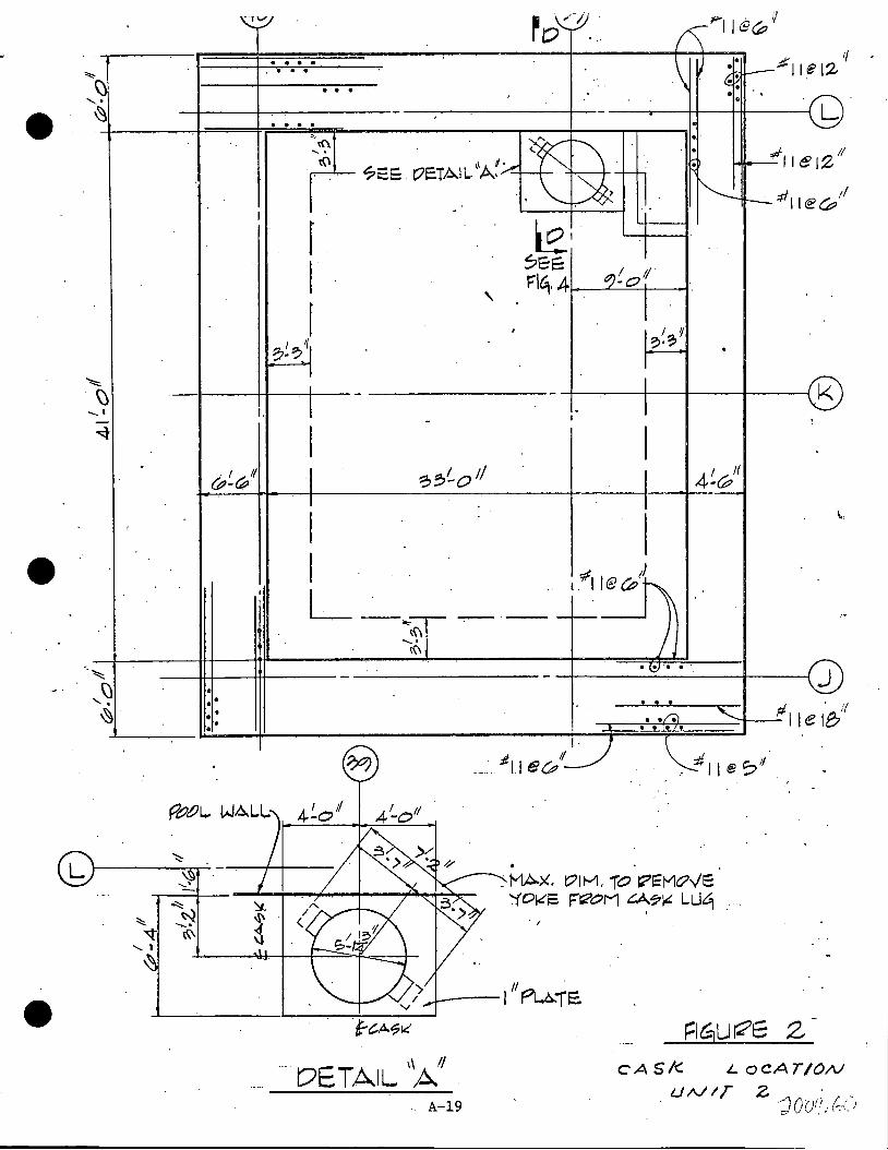
F~gures 2 and 3 show the locations of the cask for unit 2
and unit. 3. Figure 4 shows the cross-section of the connection
showing the details of reinforcement. Total reinforcing (Avf)
passing through the joint equals 11.76 in2. The center line of
the cask is 4'-2 3/4 11 from the face of the wall, hence a/d ratio
= 0.47. Since a/d (!,the Shear-friction concept can be appliedo
Hence the shear capacity of the joint per foot length,
Vu.= ¢ (fy) )J. (Avf) = 0.85 (60) (1.2) (11.76) = 718.3 K/ft.
or Vu = ¢ (vu) bd = 0.85 (.800) (12) (100) = 816 K/ft.
See Appendix IV for the above equations.
Applied load is distributed over a total length of joint which
. is equal to
L = 3 (Slab Thickness) +-Cask-Diameter = 23'-10"
Hence total applied shear load per foot length of the joint
= 83 + (9900/23.833) = 498.4 K.
Hence the Loqd Factor against cracking = 718.3/498.4 = 1.44
The 6'-3" thick slab below the cask was also checked for
shear~ Total reinforcing passing through this section is 9.36
in2 • Hence the shear capacity Vu= 0.85 (60) .(1.4) (9.36) ~ 668.3 Ks
or Vu = 0.85 (0.800) x 12 x 72 = 587.5 Ks.
Since this section is closer to the cask than the connection _-(
between the wall and .the slab, L - 2 (slab thickness) + /
Cask Diameter
= 17.5'
Only half of the 9900 Ks load will act on this section, hence
A-6
. . . . . . .

load per foot length of this section equals
I 9900 366 Ks 83 2 x 17.5 = +
Hence the Load Factor against cracking at this section =
587.5 = 1.61 366
. ,_,.,-
.1

• (C) Horizontal Drop.Normal to the Wall
(a) Velocity of Impact
.. '
It is postuleted that, while the cask i~ just about
to ~ome into or out of the f'uel pool, it is dropped.
In order for the cask to tilt into the pool, the
axis of the cask must fall inside the pool. See
figure I-2, Appendix I. After dropping on the edge
of the pool w~ll, the cask will tilt into the pool.
For this case a horizontal drop has been postul~ted
and ena.-lysed. Using the equations presented in
Appendix I the velocity of impa.ct was found to be
43.9 fps. (b) Depth of Penetration
With a velocity of impact of 43.9 fps and the contact
area of 1008 in2., the total penetration of the cask
was found to be 4.5" using the modified Petry formula·
presented in Appendix II.
·. ( c') Deformation of Cask on side ·
Section 4 of Appendix V presents the deformation
characteristics of the cask for si~ different orientations
The average deformation of 3.6" was used for the analysis.
(d) Eguivalent Static· Force on the Slab
The energy.of the falling cask,
E = ·i: in ~2 = 4189.6 K'
Since this is a plastic impact condition and the approxi
mate mass ratio of the effective slab portion to the
mass of the cask is unity the .energy absorption factor * ' eq~als 0.5 •. Hence the energy to be absorbed by the
slab upon i1I1pact A-8 ' ' ~ f'lp; /',/ . .t.ly:''
<c:f"VV -ii .1 i
I

E = 2094 K' ..
Fo:r a suddenly applied constant force of
E F = a = 3104 Ks
And time required to come to rest,
Distance td = Average Velocity = 0.0923 sec.
The Dynamic Load Factor for this forcing function is
2.0. Hence the equivalent static load applied to the
slab will be 6208 Ks.
However, if the energy absorption is not uniform
during the $topping distance of 8.1", the forcing
function would have different characteristics than
the one just-discussed. Assuming that a qµarter of·
the total energy is absorbed in first 2.7", a half of
.the total energy is absorbed in the next 2. 7" and the
remainder is absorbed in last 2.7 11 , it can be shown
that the peak load would be 4655 Ks. For.this case,
an idealized equilateral triangular forcing function
with the peak force of 4655 Ks occuring at about 0.045
sec. can be used. The maximum Dynamic Load Factor for
t~is case is 1.5 and hence the equivalent static load
applied tQ the slab will be 6983 Ks •
•. "f
* Chelapati, Kennedy and Wall, .,.
"Probabilistic Assessment of Aircraft Hazard for Nuclear Power
Plants" Nuclear Engineering and Design 19 (1972)
A-9

(e) Pool Slab Capacity
The equivalent static load of 6983 Ks was distributed as i
. a line load over a total length of 31. 7 ( 5' + (17'-4) + 1.5~ · This line load was broken down into five point .loads and the
moment and shear coefficients* were obtained. The tensile
stresses in the top reinforcing were found to be 57.6 Ksi and
54.7 Ksi at the most critical points for the dead, live, cask
drop and thermal loads. The punching shear stress was found to
be 120 psi thus giving a load factor (against punching failure)
of 2.
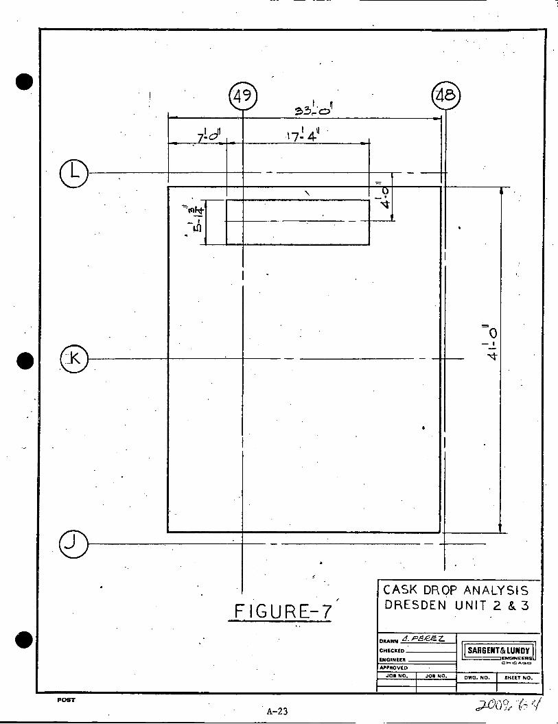
(D) Horizontal Drop Parallel to the Wall
It is very likely ·that the cask, as it falls horizontally,
can hit the pool slab as shown in figure 7. The equivalent static
l,oad on the sla'Q will be 6983 Ks. as described in section I (c) ..
Since the impact is near the edge, shear across the connection
between the wall and the slab will be most critical. Shear
capacity of this connection as·ctetermined earlier using the shear
friction concept equals 718.3 K/ft •.. The applied load is
distributed over a length L = 33'. Hence the total applied
load per foot length of the connection ·=
Hence, the Load Factor against cracking =
.-I
* Londe & James
6983 + 83 -rr-718.3/294.6
"Handbook .of Concrete En~ineering" pp~ 9-70
NcGraw Hill Book Company, .Inc.
= 294.6 Ks.
= 2.44

• )
II. REFUELING FLOOR
(A) Decontamination Pit··
The cask.will be brought to the Decontamination pit and will'
be raised above the pit for cleaning it from underneath. Figure
5 shows the location of the pit in the building and the rein
fo~cing in the pit slab. For the analysis the minimum constant
thickness of 20" was used conservatively neglecting the slopes •.
The slab was transformed into an equivalent fixed ended beam of
9. 5 I Width·•. The effect Of Compression reinforcement WaS .
~eglected·conservatively.
The follo~ing procedure was used to determine the energy ·
capacity of the beam, and hence the maximum drop height.
1. Positive and negative ultimate moment capacities of the
beam .were found using the ACI Code 318-71.
2. For the given cross-sectional propertiee, the curvature
was obtained using
·~·· = Maximum concrete compressive strain Neutral Axis Pepth
where maximum concrete compressive strain
0.5 * 0.003 + z
and z = shear span in-i~ches.
3. · The total rotation occuring.- in length d/2 was found· by
the expression,
where d = depth of the beam.
A-11
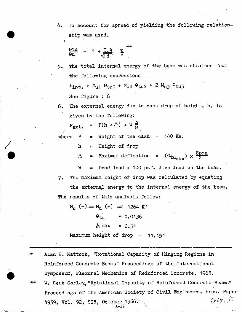
4. To account for spread of yielding the following rel~tion-
9 ship was used,
I e
Qtu Qu = 1 + 0.4
"f°Q
** 'Z.
Ci
5. The total internal energy of the beam was obtained from
the following exprespions
Eint. = r\i1 Qtu1 + Mu2 Qtu2 + 2 Mu3 Qtu3
See figure : 6
6. The external energy due to cask drop of height, h, is
given by the following:
Eext. - P(h + 6) + W ~
where· P = Weight of the cask = 140 Ks.
h = Height of drop
A = Maximum deflection = (Q ) x Span u turn ax 2
W = Dead load + 100 psf. live load on the beam.
7. The maximum height of drop was calculated by equating
the extern8:1 energy to the internal energy of the beam.
The results of this analysis follow:
Mu (-)=Mu (+) - 1264 K1
Qtu = 0.0136
Amax = 6.5" Maximum height of drop = 11.15"
* Alan Ho Mattock, "Rotational Capacity of Hinging Regions in
Reinforced. Concrete Beams" Proceedings of the International
Symposeum, Flexural Mechanics of Reinforced Concrete, 1965.
** W. Gene Gorley, "Rotational Capacity of Reinforced Concrete Beams"
P~ocee~i,ngs of the American Society of Civil Engineers, Proc. Paper
49,39, Vol. 92, ST5, October 1966>"- 'J--Orh .. <:~ A-12 \

I e
It is recommended that the cask be raised··a maximum of 9 11
for safe cleaning operation, ·and 6 11 while traveling to and from
the Decontamination pit.
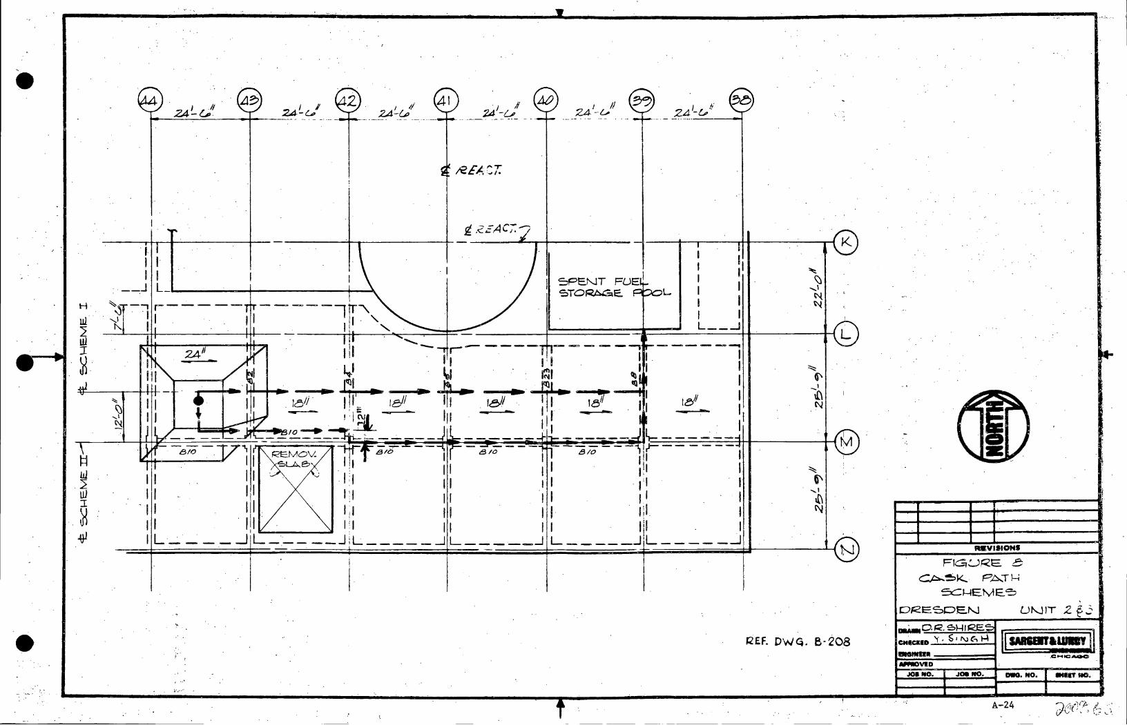
(B) Travel Path
To determine a safer path for the cask travel between the
Decontamination Pit and the Spent Fuel Pool the following two
schemes (Figure 8) were evaluated using the procedure described.
in section II (A).
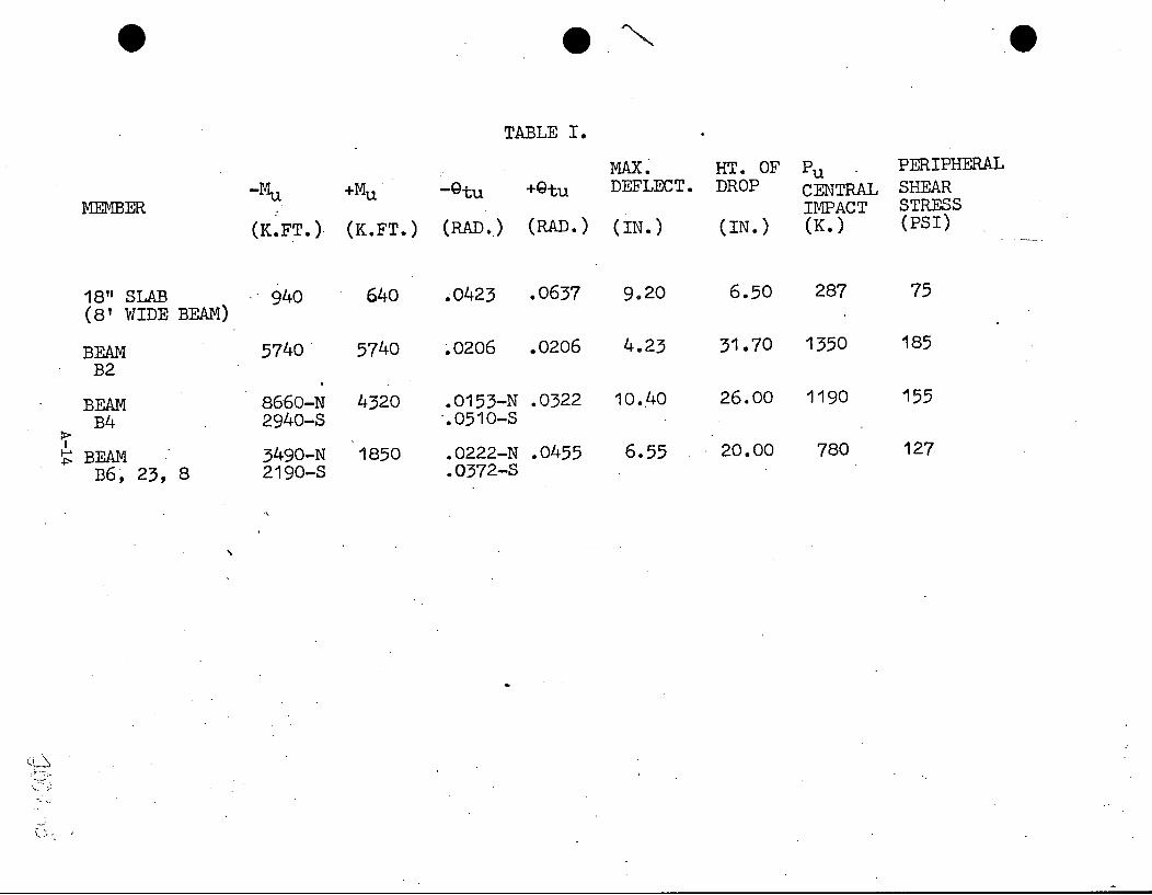
(a) Scheme I
This is a more direct path from the Decontamination
pit to the Spent Fuel Pool. The cask travels over the 18"
slabs and the beams B2, B4, B6, B22 and BB. Table I shows
the important parameters resulting from the evaluation of
this scheme.
(b) Scheme II
This scheme presents a path over the. floor beams. The
results of the analysis evaluating this scheme are presented
in Table II.
The results of scheme I indicate that the. maximum height the
cask can be lifted above the floor should be less than 6.5 11 •
This dil1lension results from· the capacity of the 18 11 slab .•
However, scheme II.indicates that the cask can be raised up
to a maximum of 22 11 • For the reasons of conservatism scheme II . /
is recommended with the cask lift of 6 11 •
A-13 "1 1'1- 1'l ... \ . ~ .:, ./ d-"\< \.~ / / I '
·e
TABLE I.
MAX~ HT. OF Pu PERIPHERAL
-Mu +Mu -Qtu +Qtu DEFLECT. DROP CENTRAL SHEAR MEMBER IMPACT STRESS
(K.FT.) (K.FT.) (RAD • .) (RAD.) (IN.) (IN.) (K.) (PSI)
18" SLAB .· 940 640 .0423 .0637 9.,20 6.50 287 75 (8' WIDE BEAM)
BEAM 5740 5740 ~0206 .0206 4.23 31.70 1350 185 B2
BEAM 8660-N 4320 .0153-N .0322 10 •. 40 26.00 1190 155 B4 2940-S ·.0510-s
P> I
~ BEAM 3490-N 1850 .0222-N .0455 6.55 20.00 780 127 B6, 23, 8 2190-S .0372-S
.,
'
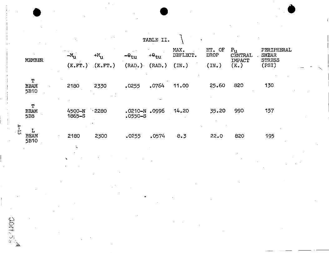
. ; . • •• TABLE II. \
:MAX. HT~ OF Pu PERIPHERAL -Mu +~ -Gtu +Qtu DEFL:OCT. DROP CENTRAL . SHEAR
MEMBER IMPACT STRESS (K.FT.) . (K.FT.) (RAD.)· (RAD.) (IN.) (IN.) (K.) (PSI)
....... '
T BEAM· 2180 2330 .0255 .0764 11.00 25.60 820 130 5B10
T BEAM 4500-N ·2280 .0210-N .0996 14.20 35.20 990 157 5B8 1865-S .0550-S
:i> I L I-' V1 BEAM 2180 2300 .-0255 .0574 8.3 22.0 820 195
5B10 •\
'
•
~j . -
. .J;::..

9·
e.
DISCUSSION & CONCLUSIONS
,--
As: described earlier, for the travel path of the cask
between the Decontamination Pit and the Refueling Floor, two
schemes were con~idered. Scheme II was f ot,llld to be more
conservative and hence the path shown in figure 8 (Scheme II) is
recommended with a cask lift" of 6 11 • At two places the cask will
pass over 4 11 curbs. The ·cent~r line of the cask should be 1'-0"
North of column Row M, to assure tilting, if any, away from.the
opening in the Refueling floor between column rows 42 and 43.
Wllen over the Refueling floor even if the cask drops in a tilted
position, there .is no .Po.ssibili ty of its tipping since the angle
at which the cask will tip over is approximately 15° (See
Appendix V) • To attain this angle the cask has to be 15" above
the flqor. Over the Decontaimination Pit the cask may be raised
up to 911 for decontamination purposes.
While dropping through the water the cask will have a tendency
to attain vertical position ~s it moves through -Che water because
of the lea~t water resistance (drag force) for the vertical fall.
However, if the cask hits the pool slab in an inclined position,
there will be more local damage to the pool, but the overall
effect will be less severe· than the perfect vertical fall. This
is attributed to the· fact that the center of gravity of the cask
moves larger distance to come to rest, when it hits the slab in
a tilted position. The Load Factor against cracking of the slab .I'
due to·shear for the vertical drop is found to be 1.44 and hence
no cracking is e~ected.
A-16
/ !
The horizontal drop normal to the wall will not be as severe I
as considered in this analysis because the e~f ect of fuel
assembiles and fuel racks in absorbing the energy has been
;ignored.
In generai, the Refueling floor and the Spent Fuel Pool
have been found to be adequate tor withstanding a cask drop
accident.
/
A-17

~00 ...
··WOO~
. .. _4000.
. ~28hK ·
?OOO: .
.. .2000 ..
1000~ ...
. 007e,4
/" : ... -· &J~72. K
n I
F=1
_.01 ·.02 _ .o~ .04 ... o~ _ .o<P. ~Ee..
VE.R. Tl C.A I- DROP
- Tlt1~ . Fl~UK'E. I
. · FOl?ClhJ~ FUtJCTIO~? O~ POOL SLAB
A-18 ~)n'Y/ ~)o Cd- i , I
......... - --- ~_.-·•
... ---····· ..... -------····~··· , .... ··-- ····-· ........ ·-·~·-····-. ·····-· -· .. ,,. -·· ... : . '·" .. .
....._I
. I _,._II ~-w
••
•
I.
.... . . . ' it if -
11e12 ••• •
.... ~
\{'\ ..... -~-1--- ?EE C/E.TAIL. 11A~,,,-:· c..L__Jl____ -~ ~-411e12/
. -11'11@~;/
~~:;'/
f I r
... DETAIL 'A'. . A-19
'
I·
ill I e (;? 11
• ~MAX. l?ll'-1. jO "Et--"lc?ve "(01-'S. F'~OM CA7~ LL.19
' . ,
CA Sk. '- ocAT/ON
. u Ni T z ·;Joor;.:!~{)

;;r;C-11~12 I
- •
.?'I !~ 1:z/ tf-1·1 e a:i'1
.
•
CASk t. ocA TIOAI
I~ ~- .......
~~0 11
LJNIT 3 MAX.. 1?11-1. TO r.?Ef..10v'E: '(01'-.E. F"t"~M CA.~~ L..LJ9
. '
. •
• • •
•
--, I I I I I
I _· _ _J
r •. L
• . • • .
• • •
I I/ ~.:;
/. I/
I G? -0
• •
y ~"'t \\\ ~ :<{ '-...t ,,,,_ '1 -;~
':::::: (.)
' . ~
...... ,
.~-!--------- ti\
~
;;co crl l:7 J DETAIL ''A

-+-----__ __;.. _ __..,;.._
- '
.-,.
~ . I . N
t-'
-~~~I •r -·\l • ....
tti I~ e:,u t;iO'i'/GL5
. ' ..
. . '*1IC:?~ 1' . , D~~/E~:;:; -.,_
, y •
. . . . ' ... \,
I II .(A ,.-
1
.; . .~ ..
· I ::-:· . .. ):··.;·.· ...
' \ '~· _,
·'.
. . '. : i' /''
; ... ··~ "·
. 'l
I .. ·. ;.·.
) ' ;. .
, I .
·.: ·s~";3 (CAsi::. L>IAMElcR. . . '.· ?t ..
... . ·· .. ! :.
' ,. J :.: .. \····. 'r= IG'LJ RE.. . 4 · .. ,.:...--"".'- .. , . ; ... k~,/· .... ·
. ·:·> ! . , ~--E. C • .rD ~/~/ ·. . DWG. P.:r.- '2 ·1 g ·'
/ ..
••
··. .. '
·}·-- Ge:)N~fF<r .!01 · e: L. • '5> 7 7 • ~ '' ·-'!
... ;
.. ~ · . . · ....
. · ·; •i I· ~ II 1· i ~ . . :.~
: ;;,.-' .. -.,,. .. • •<;d
\.
.. ' .
; . .. . (

'
Mu;;
·-'
FIGURE u
POST A-22
, ..
) Mo.z
CASK OJ<OP
~LY5/5
0.QE50EN U1'JITSZ4.8
SARGENTUUNDY
APPROVED
JOI NO. JOD NO. DWG. NO; SHEET NO.
! A9 .=,'· ~ ~ ,...o·
7!01 .17!4'1
cg -
' -~
""'°tnht _, -·--· ~ ..
I -
-_k -
I
j -•
/,
-. FIGURE-7
POST
A-23
-
zte
-0 - . ~
I
•
I
""" 0 - ' -
- ~
• I
--
CASK DROP AN ALY SIS DRESDEN. UNIT 2 & 3
. DllAWN Lf. Pe/2.e z. CHECllED---l
ENGINEER
APPROVED
J08 NO. JOI NO.
SARGENT~ LUNDY ENGINEERS C~IC4'GO
DWG. NO. SHEET NO.
I
I I
. '
-~ ~· .. . . ·
H ..
ul 2 u1 I ~·
~ w 2 uJ I
.~ -4J1
~ --...I I'\.
24'' -
"""' ~ -...I
t't
'."
J I/ 24-LJ,
rl - -A,...._ __ ~ :c.:=. '-;. I
SPENT FUEi ~TO~E. ~_...L.
I
I
I I 11 I I I I I I I I L __ _J
J2EF. DWQ. 8-208
IWYISIONI
FIGJ,:_J,Q'E. 8 CP;.~K.. PAT)-;
=x::::~EME. ~ '
Of<E5PE.N U~IT 2 f_;
J08 NO. .109 NO. DllQ. NO. -IT JIC.
. ''" A-24

/
APPENDIX- I
VELOCITY OF ·CASK
. I. A BOVE WATEe
V:~
wh e. re. ~ :: () i-a.. vit0i.i: i o ned
h :: h e ij ht o.f -f o. 11 a. b oire w°' tw
For t/,.e,. cJr·o P I V1 t~e, f00' h 10, ss'
JI IN WATER
V- - F\g - k. V'L = ~ (~;)v . '
3L - ~ - v'l =- v ( dv )v k. k ~k d;:
f .$_ d)G =- ( w . ~ 2 .Jv . v }. T-~-v
Y=V 0
.. I t /V !k_ V2) C;=-"2. ~\k-k. -o
~~x- r]l-~-V'2. J v-=L k k. 0
. ~ w - lli v'Z. k Ir.. -
w Fl '1 - - .!..J2. - v k. k. 0
"f- - 't _ y-z A-25
/ /
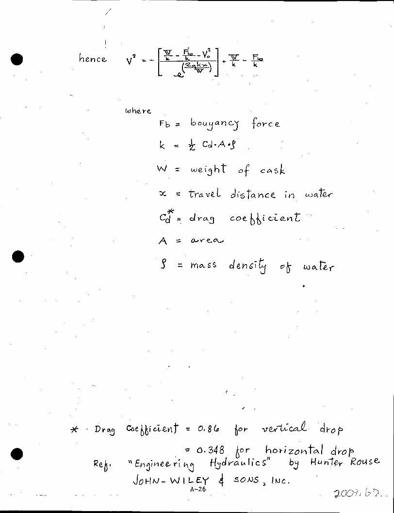
hence.
w he. t-e
Fb ;:: boujanc)' f oYC e.
k I Col·A ·J -::: "Z
w = wei3h t of CC\$k
:::c = trt1. vt L dis To. Yice. .
lAJ a. t '2-<" 1n
* d Y"O..j coe.b~i.c;l.e.vit · Cd :::.
A ::; Q.J.V""e.~
e· r devisiG w °" b,(" - mo.. s s "~ -
./
. -== o. 348 6or horl zov-. to./ d~op \\ Er1ji1-1ee..w··I hj Hjcl VO. I.A Ii cs" bj Hun 1f,-y KOU s e.
Jo H rv - W I L. E. Y 4 .so NS ) I "1 c . A-26

-· .;
I
A ..
c..~.
~------4- r '°
. I ~ --+---EL. Gl2-0 ~
l - ..
-a' ~ ·=
. II (.l't
(..!. -· r-i I t<)
I -1 I I I I I I I c. Gi.
I ·-I EL. 5 741- ·~}
I I
. I.
VERTICAL DROP
F·I G URE I-1 A-27·
~il•.

I n ' c. ~··
.... .. -cO ' ' LI\ ro ~· l.O
,.:. ' .
\ 0 I ' \
r-·--- -.,-- - - ---, I I c.~. I
...r:
I ----- I
l..., ----t------1
l -
l -. UI (C')
" (I.
j 17! 4 _,
L r-----------, I . .c.cai. I I --- • -----.--~
HORIZON:TAL DROP.
FIGURE 1-2
A-28 ·
Co co
"
-a-_,
"" \1l
' I" u tEL.<il2-0
WATER LEVEL /JVR.!N.Gt RER/E.UNGt
"
.· I 11 -----E.L. ~14·:)

e.
A PPENDlX JI
CON Cf2ETE PENETl2ATION
·• -· . The fonnula used to calculate penetrationdepth of rigid type missiles
is .the Petry formula:
where
D' :;: KAV'R '* ( Mod ifi"ed Pe..tr-j formula.)
D' = depth of penetration in slab of thickness T(ft.)
K = Material property constant
= 4.76xlo-3ft3 /lb. for reinforced concrete
A = Sectional mass, weight of the missile per unit cro~s
sectional area (lb/ft2)
V'. = . Velocity factor = Log 10 (1 + 21 ~~00 )
where V = velocity of missile in ft/sec.
R = Thickness ratio . D'
= 0-- = (l+exp[-4(a'-2)])
where
.. bY a'
a' ,the penetration ratio is given
=T=_T_ D KAV'
•
* .. c. v. MooeE.,
,, The Vesij"1 of (30,yric~des for
A-29

APrE"1DIX III
T£MC..O OUT PUT
DRESDEN FUEL POOL SLAB OL < LL < THERMAL GRADIENT 50F
SECTION WIOTHCIN>---------------------SECT I ON ·TH I CKNESS (IN>------------------CONCRETE OENSITY(LBICU•FT>-------------CONCRETt COMPRESSIVE STRENGTH(PSI>-----CONCRETE MODULUS Of ELASTICITY<KSIJ·---· STEEL MODULUS Of ELASTICITY(KSI>-----~-STEEL YIELD STRENGTH CKSI>-------------SPRING CONSTANT(KIPS/INJ·---------·----COEFFeOF THERMAL EXPANSION(/O•F•>-------AXIAL LOAOCKIPSJ-----------~------------
12.00 ·100.00 l'+S•OO
'f000•00 36'f'h15
29000•00 60•00
•00 1556-05
.oooo BENDING MOMENT(FT•KIPS)··--------------• .3210+03 INSIDE TEMPERATURE(D•F•>--------~------- 25•00 OUTSIDE TEMPERATURE(D.Fe)·-------------- •25•00 REINFORCEMENT DATA LAYER DISTANCECINe)
1 3•00 2 72•00 3 102•00
••••MATERIAL PROPERTIES ARE ASSUMED NON-LINEAR••••
AREACSQelN•J 3•120 6•2'f0 l•OOO
DISTANCE OF C•G•Of UNCRACKEO TRANSFORMED SECTION FROM INSIDE<IN•Jc ~'f•Ol
•
FINAL OUTPUT AFT~R APPLYING THERMAL GRADIENT
DISTANCE OF NEUTRAL AXISCIN.J-----------STRAIN AT INSIDE Of SECTION·----------STRAIN AT OUTSIDE OF SECTJON·---------JNSIDE CONCRETE STRESSCKSI>-----------OUTSIDE CONCRETE STRESSCKSIJ------------INSIDE STEEL STRESSCK5I>·-~---------OUTSIDE STEEL STRESSCKSIJ------------
FINAL INTERNAL fORCECKIPS>=
FINAL INTERNAL MOMENTCFT•Ktps>= •l'f65+03 /
THERMAL MOMENTCFT•KIPSJ• ••17'f5+03
A-30
86•52 •el86'f-Oj
t'f628-0't .oooo .1s5s
-s.21e1 1. 93'f't
C TENS I LE) ( C OMFR.E SSIVE)
. .. ··- ··-·-····· ...................... _ ..... ...... .. ..... -- ·~-- ·- .. , ..

/
I '
i ···;··· - '.. T ·- ·- -·--------;-------···-;--~---~
! I , ! L---·-·f·- .. ·-..!.-·--+--~--·----•-··-:...---·-~---. ·-···· ·--'" ·······•····--·-···;·····- --: .
. !------:----:--- -j- .. ·---~ --;·---C---~--·T---~ c ___ J ___ _, -------~-----1- - - l -: ......... : ---r ---- : -.-' __ ; . -- ---.----+-- ... ------i
0-•••• ••••i••H• •••••>
' ; ' ~ ..... .,.__,_. ___ _.,
. l
; __ ..
-~ N
.. !'- ......... --· .. _ ..
..... - ·--- ; --- -
. -·--··r···
• • -+---'2-=-~ IJ_ ---
i i ' '
-· ·-·. ·········- •--··· .. ..!--------· ·····-·····----....!.--.. ---' _j__ . , ! I i i
........ ,, .. ______ --- ...... •· -·-·- ... •. ___ ..... __ _J_ __ +-----i :
- ·-· ... -----·-·-. ···-· .. i .. - .•. .... I
--e·o·e O· ._4,#"ll ;
' ..... -· ····~------~~ ... -·. -· .. ---- ....
• 1.# . .9 ...
i -- ...• ------ ···-- .................... .
'TEMC01 A~AL'(SIS
SE..C TION AT. SLAS-\!VALL JUtJCTJOt\J
NOTE: ~OT .INCLU'DED
FIG U i2E J:Ir-1 ·
A-31

r AP PE l'0 DIX' :rsl:
ACI Standard
BuH~h~g Code t:;e~~~reme~ts 1or ~eh"iiorce~ Cc~creie (ACD ·31.0-71)*
EDWARD COHEN Chainnan
W. C. E. BECKER W. BURR BENNETT, JR. DELMAR L. BLOEMt
··FRANK B. BROWN T.Z. CHASTAIN WILLIAM D. CROMARTIE OWEN L. DELEY ANTE JAMES N. DE SERIO
·.FRANK G. ERSKINE NOEL J. EVERARD PHIL M. FERGUSON ASHBY T. GIBBONS, JR. WILLIAM A. HEITMANN
Reported by ACI Committee 318
EIVIND HOGNESTAD EUGENE P. HOLLAND FRITZ KRAMRISCH ·r. Y. LIN MICHAEL A. LOMBARD ROBERT F. MAST WILLIAM Y. MERKEL ROBERT B. B. MOORMAN KEITH 0. O'DONNELL DOUGLAS E. PARSONS EDWARD 0. PFRANG W. G. PLEWES RAYMOND C. REESE
GEORGE F. LEYH Secretary
THEODORE 0. REYHNER PAUL F. RICE FRANCISCO ROBLES PAUL ROGERS JOHN A. SBAROUNIS MORRIS SCHUPACK CHESTER P. SIESS I. J. SPEYER JOHN P. THOMPSON M. P. YAN BUREN A. CARL WEBER GEORGE WINTER ALFRED ZWEIG
This Code covers the proper design and construction of buildings of reinforced concrete. It is written in such form that it may be incorporated verbatim or adopted by reference in a general building code, and earlier editions have been widely used in this manner. .
Among the subjects covered are: permits and drawings; inspection; specifications;. materials; concrete quality; mixing and placing; formwork, embedded pipes, and construction ·1oints; reinforcement details; analysis and design; strength ·and serviceability; flexural and axial cads; shear and torsion; development of reinforcement; slab systems; walls; footings; precast
concrete; prestressed concrete; shells and folded plate members; strength evaluation of existing structures; and special provisions for seismic design.
The quality and testing of materials used in the construction are covered by· reference to the appropriate ASTM standard specifications. Welding of reinforcement is covered by reference to the appropriate AWS standard.
Keywords: admixtures; aggregates; anchorage (struC:tural); beam-column frame; beams (sup-. ports); building codes; cements; cold weather construction; columns (supports); combined
stress; composite construction (concrete to concrete); composite construction (concrete and steel); compressive strength; concrete construction; concretes; concrete slabs; construction joints; continuity ·(structural); cover; curing; deep beams; deflections; drawings; earthquake resistant structures; embedded service ducts; flexural. strength; floors; folded plates; footings; formwork (construction); frames; hot weather construction; inspection; joists; lightweight C'oncretes; loads (forces J; load tests ( strudura I J; materials; mixing; mix proportioning; modulus of elasticity; moments; pipe columns; pipes (tubes); placing; precast concrete; prestressed concrete; prestressing steels; quality control; reinforced concrete; reinforcing steels; roofs; serviceability; shear strength; shear walls; shells {structural forms);· spans; specifications; splicing; strength; strength analysis; structural analysis; structural design; T-beams; torsion; walls; water; welded wire fabric.
•Adopted ns a standard of the American Concrete Institute at its 19i0 Fall Convc:1tion, St. Louis, Mo., Nov. 5, 19i0, as amender!: rntifie<i by letter ballot Feb. !l, 1971. ACI 318-71 supersedes ACI 318-63.
Copyright © 1970, American Concrete Institute. All rights reserved Including rights of reproduction and use in
any form or by any me:ins, including the making of copies by
A-32
any photo process, or by :my electronic or mechanical device, printed or written or oral, or recording for sound or visual reproduction or for use in any knowl~c\ge or rctr1cvol system or device, unl~ss p~rrnisslon in writing is obtained from the copy-right proprietors. ·
tDeceased

l
shall be proportioned such that their (Adbir.Hv of the shear about the centrpid of the critical section defined in Section· 11.10.2. Shear stresses shall be taken as varying linearly about the centroid of the critical section and the shear
stress v,. shall not ;exceed 4'/ f /. 11.14-Special provisions for brackets and corbels
11.14.1-These provisions apply to brackets and corbels having a shear-span-to-depth ratio, a/d, of unity or less. When the shear-span-todepth ratio a/d is one-half or less, the design provisions of Section 11.15 may be used in lieu of Eq. (11-28) and (11-29), except that all limitations on qua'ntity and spacing of reinforcement in Section 11.14 shall apply. The distance d shall be measured at a section adjacent to the face of the support, but shall not be taken greater than twice the depth of the corbel or bracket at the outside edge of the bearing area.
11.14.2-The shear stress shall not exceed
1) .. ~ [ 6.5 _ 5.1 ff.I 1 - 0.5 : J x
. { 1 + [ 64 + 160 ·~ J p} y fc'
(11-28)
. where p shall not exceed 0.13fc'/f71 and N,,/V,, shall not be taken less than 0.20. The tensile force N., shall be regarded as a live load even when it results from creep, shrinkage, or temperature change.
11.14.3-When provisions are made to avoid tension due to restrained shrinkage and creep, so that the· member is subject to shear and moment only, v., shall not exceed
v .. = 6.5 ( 1 - 0.5 ~ )( 1 + 64 p., )-v f c' (11-29)
where . Aa+A,.. P~= -bd-
but not greater than
.... 0.20 ~~ :~ i • •• <t
and A11 shall not exceed A,. 11.14.4-Closed stirrups or ties parallel to the
main tension reinforcement having a total crosssectional area A 11 not less than 0.50A3 shall be uniformly distributed within two-thirds of the effective depth adjacent to the main tension reinforcement.
11.14.5-The ratio ,o = A,/bd shall not be less than 0.04 (f / /f 7;).
11.15-Shear-friction ·
11.15.1-These provisions apply where it is inappropriate to consider shear as a meas4re of
BUILDING CODE REQUIREMENTS A-33
diagonal tension, and particularly in design of reinforcing details for precast concrete structures.
11.15.2-A crack shall be assumed to occur along the shear path. Relative displacement shall be considered resisted by friction maintained by shear-friction reinforcement across the crack. This r~inforcement shall be approximately. perpendicular to the assumed crack.
11.15.3-The shear stress v., shall not exceed 0.2f c', nor 800 psi.
11.15.4-The required area of reinforcement A,,1 shall be computed by
:·~A. V .. ,-- -1J - c/Jf 11µ.
(11-30)
The design yield strength f 11 shall not exceed 60,000 psi. The coefficient of friction, p., shall be 1.4 for concrete cast monolithically, 1.0 for concrete placed against hardened concrete,_ and 0.7 for concrete placed against as-rolled structural steel.
11.15.5--Direct tension across the assumed crack shall be provided for by additional reinforcement.
11.15.6-').'he shear-friction reinforcement shall be well distributed across the assumed crack and shall be adequately anchored on both sides by embedment, hooks, or weld.L11g to special devices .
11.15.7-When shear is transferred between concrete placed against hardened concrete, the interface shall be rough with a full amplitude of approximately ¥.i in. When shear is transferred between as-rolled steel and concrete, the steel shall be clean and without paint.
11.16-Special provisions for walls •
11.16.1-Design for horizontal shear forces in the plane of the \Vall shall be in accordance with Section 11.16. The nominal shear stress, Vu, shall be computed by ' .. - .
Vu 1'u.= .cphd (11-31)
.where ~ shall be taken equal to 0.8l, •. A. larger value of d, equal to the distance from the extreme
·compression fiber to the center of force of all reinforcement in tension, ma;Y be used when determined by a strain compatibility analysis.
11.16.2-The shear stress carried by the concrete, v"' shall not be taken greater than the lesser value co;nputed from
Ve= 3.3-y f / + 4~"h (11-32)
and

. ;,,~··
EDWARD COHEN Chairman
W. C. E. BECKER W. BURR BENNETT, JR. DELMAR L. BLOEM* FRANK B. BROWN T. Z. CHASTAIN WILLIAM D. CROMARTIE OWEN L. DELEY ANTE JAMES N. DE SERIO FRANK G. ERSKINE
· NOEL J. EVERARD PHIL M. FERGUSON
. ASHBY T. GIBBONS, JR. WILLIAM A. HEITMANN
Reported by ACI Committee 318
EIVIND HOGNESTAD EUGENE P. HOLLAND FRITZ KRAMRISCH T. Y. LIN MICHAEL A. LOMBARD ROBERT F. MAST WILLIAM Y. MERKEL ROBERT B. B. MOORMAN KEITH 0. O'DONNELL DOUGLAS E. PARSONS EDWARD 0. PFRANG W. G.PLEWES RAYMOND C. REESE
GEO'RG'E F. LEYH 'secretary
THEODORE 0. REYHNER PAUL F. RICE FRANCISCO ROBLES PAUL ROGERS JOHN A. SBAROUNIS MORRIS SCHUPACK CHESTER P. SIESS I. J. SPEYER JOHN P. THOMPSON M. P. VAN BUREN A. CARL WEBER GEORGE WINTER ALFRED ZWEIG
Because the 1971 ACI Building Code is written as a legal document so that it may be incorporated verbatim or adopted by reference in a general building code, it cannot present background details or suggestions for carrying out its requirements or intent. It is the function of this Commentary to fill this need. · · The Commentary discusses some of the considerations of the committee in developing the Code with emphasis given to the explanation of new or revised provisions that may be .unfamiliar to Code users. ·
References to much of. the research data referred to in· preparing the Code are cited for the user desiring to study individual questions in greater' detail. Other documents that provide sug
. gestions for carrying out the requirements of the Code are also cited. The chapter and section numbering of the Code are followed throughout .
Keywords: admixtures; aggregates; anchorage (structural); beam-column frame; beams (supports); building codes; cements; cold weather construction; columns· (supports): combined stress; composite construction (concrete to concrete); composite construction (concrete and steel): compressive strength; concrete construction; concretes; concrete slabs; construction joints; continuity (structural); cover; curing; deep beams; deflections; drawings; earthquake resistant structures; embe_dded service ducts; flexural strength; floors; folded plates; footings; formwork (construction); frames; hot weather construction; inspection; joists; lightweight concretes; loads (forces); load tests (structural); materials; mixing; mix proportioning; modulus of elasticity; moments; pipe columns; pipes (tubes); placing; precast concrete; prestressed concrete; prestressing steels; quality control; reinforced concrete; reinforcing ste~ls; roofs; serviceability; shear strength; shear wal Is; she I Is (structural forms); spans; specifications; splicing; strength; strength analysis; structural analysis; structural d.esign; T-beams; tor-sion; walls; water; welded wire fabric. ·
•Deceased reproduction or for use in any knowledge or retrieval system or device, unless permission in writing ls obtained from the copyright proprietors.
Copyright © 1971, American Concrete Institute. All rir,hts resen:ed including rights of reproduction and use In
· any form or by any means, including the making of copies by any photo process, or by any electronic or mecnanical device, Printed or written or oral, or recording for sound or visual
A-34 '.
The content of this Commentary is the responsibility of the committee which prl"pared it. Institute authority attaches only to standards adopted as provided in the Bylaws.
/,• ...... . ,, ( .' / .
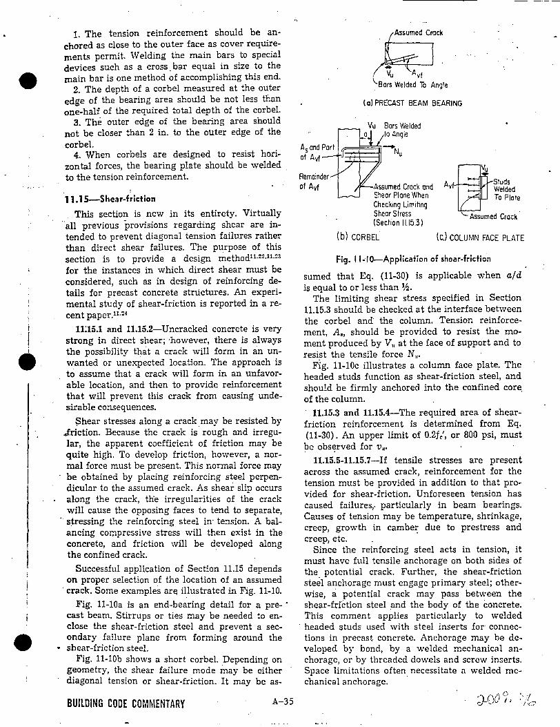
1. The tension reinforcement should be anchored as close to the outer face as cover requirements permit. Welding the main bars to special devices such as a cross. bar equal in size to the main bar is one method of accomplishing this end.
2. The depth of a corbel measured at the outer edge of the bearing area should be not less than one-half of the required total depth of the corbel.
3. The outer edge of the bearing area should not be closer than 2 in. to the outer edge of the corbel.
4. When corbels are designed to resist horizon ta! forces, the bearing plate should be welded to the tension reinforcement.
. . 11.15-Shear-friction
This section is new in its entirety. Virtually "all previous provisions regarding shear are intended to prevent diagonal tension failures rather than direct shear failures. The purpose of this section is to provide a design method11
·!?2
•11
·23
for the instances in which direct shear must be considered, such as in design of reinforcing details for precast concrete structures. An experimental study of shear-friction is reported in a recent paper.11 ·::~
11:15.1 and 11.15.2-Uncracked concrete is very strong in direct shear; ·however, there is always the possibility that a crack will form in an unwanted or unexpected location. The approach is to assume that a crack will form in an unfavorable location, and then to provide reinforcement that will prevent this crack from causing undesirable consequences.
~hear stresses along a crack .may be resisted by ..friction. Because the crack is rough and irregular, the apparent coefficient of friction may be quite high. To develop friction, however, a normal force must be present. This normal force may be obtained by placing reinforcing steel perpendicular to the assumed crack. As shear slip occurs along the crack, tlie irregularities of the crack will cause the opposing faces to tend to separate,
· s~ressing the reinforcing steel in- tension. A balancing compressive stress will then exist in the concrete, and friction will be developed along the confined crack.
Successful application of Section 11.15 depends on proper selection of the location of an assumed
·crack. Some examples an: illustrated in Fig. 11-10.
Fig. 11-lOa is an end-bearing detail for a pre- · cast beam. Stirrups or ties may be needed to enclose the shear-friction steel and prevent a secondary failure plane from forming around the
• shear-friction steel. Fig. 11-lOb shows a short corbel. Depending on
geometry, the shear failure mode may be either diagonal tension or shear-friction. It may be as-
BUILDING CODE COMMENTARY A-35
f,
Remainder of Avf
t;;'T . Vu Avf '-Bars Welded To Angle
(a) PRECAST BEAM BEARING
Vu Bars Welded to Angle
Assumed Crack ond Shear Plane When Checking Limiting Shear Stress (Section 11.15.3)
(b) CORBEL
A Studs vf Welded
To Plate
Assumed Crack
(c.J COLUMN FACE PLATE
Fig. 11-10-Application of shear-friction
sumed that Eq. (11-30) is applicable when a/d is equal to or less than 1/2.
The limiting shear stress specified in Section 11.15.3 should be checked at the interface between the corbel and· the column. Tension reinforcement, A., should be provided to resist the moment produced by V,. at the face of support and to resist the tensile force N".
Fig. 11-lOc illustrates a column face plate. The headed studs function as shear-friction steel, and should be firmly anchored into the confined core. of the column.
11.15.3 and 11.15.4-The required area of shearfriction reinforcement is determined from Eq . (11-30). An upper limit of 0.2f c', or 800 psi, must be obs17rved for v,..
11.15.5-11.15.7-If tensile stresses are present across the assumed crack, reinforcement for the tension must be provided in addition to that provided for shear-friction. Unforeseen tension has caused failures,. particularly in beam bearings. Causes of tension may be temperature, shrinkage, creep, growth in cambe~ due to prestress and creep, etc.
Since the reinforcing steel acts in tension, it must have full tensile anchorage on both sides of the potential crack. Further, the shear-friction steel anchorage must engage primary steel; otherwise, a potential crack may pass between the shear-friction steel .and the body of the concrete. This comment applies particularly to welded
· headed studs used with steel inserts for connections in .precast concrete. Anchorage may be developed by bond, by a welded mechanical anchorage, or by threaded dowels and screw inserts. Space limitations often necessitate a welded mechanical anchorage.
d ·v"i 0 ···/ _l 1\_,. I: · 1· 4
' .... ', '<-~

1
/
APPENDIX V.
CASK FIN DEFORMATIONS
Ref. "Design & Analysis Report IF 300 Shipping Cask",
Nuclear Fuel Department G.E. Co. NED0-10084-1, Feb. 1973.
Fin Bending Analysis I The fin bending analysis is based on a testing program: conducted at \
ORNL and the University of Tennessee. The data and subsequent corre-
lations are considered proprietary and will not be exhibited in thi~
documen.t.
Test specimens representing single fins were mounted on an instrumented
load cell and impacted by guided falling weights from various heights.
Test data were recorded on an oscilloscope and photographea, from which
force-time relationship graphs were plotted.
From those test results a correlation was made relating fin rotation
angle, fin deflection and absorbed energy. Using this corre~ation, the
IF 300 cask fin configuration was analyzed for energy absorption and
deceleration.
To provide a degree of conservatism the decelerations were computed by
dividing the drop height (360 inches) by the deformation distance com
puted using the correlation. Those areas in close proximity to the im
pact point (e.g., v~lve boxes, closure flange and studs) were evaluated
"at twice the deceleration computed using the above method. ·
'1
Throughout all of the fin bending analyses it was conservatively assumed
that the maximum rotation angl.e for a double-hinge fin was 1. 5'1T radians.
A-36 •
•
2
·.
/ /
Corner Drop
The ~irst vertical drop is with the cask inclined such that the center of
gravity acts through the cask corner as shown in Figure V-5. The angle
of inclination is slightly less than 15°. Since the cask strikes the
sur;ace at an angle with the horizontal, the fins will undergo different
defQrm~tions d~pending on their orientations on the head (see Figure V-6
for end fin arrangement). For fins inclined at less than 10° relative to
1the contact surface, two hinges were assumed to form based on the refer
enced tests. For those fins hitting at an angle greater than 10°, a
single ~inge was assumed to form.
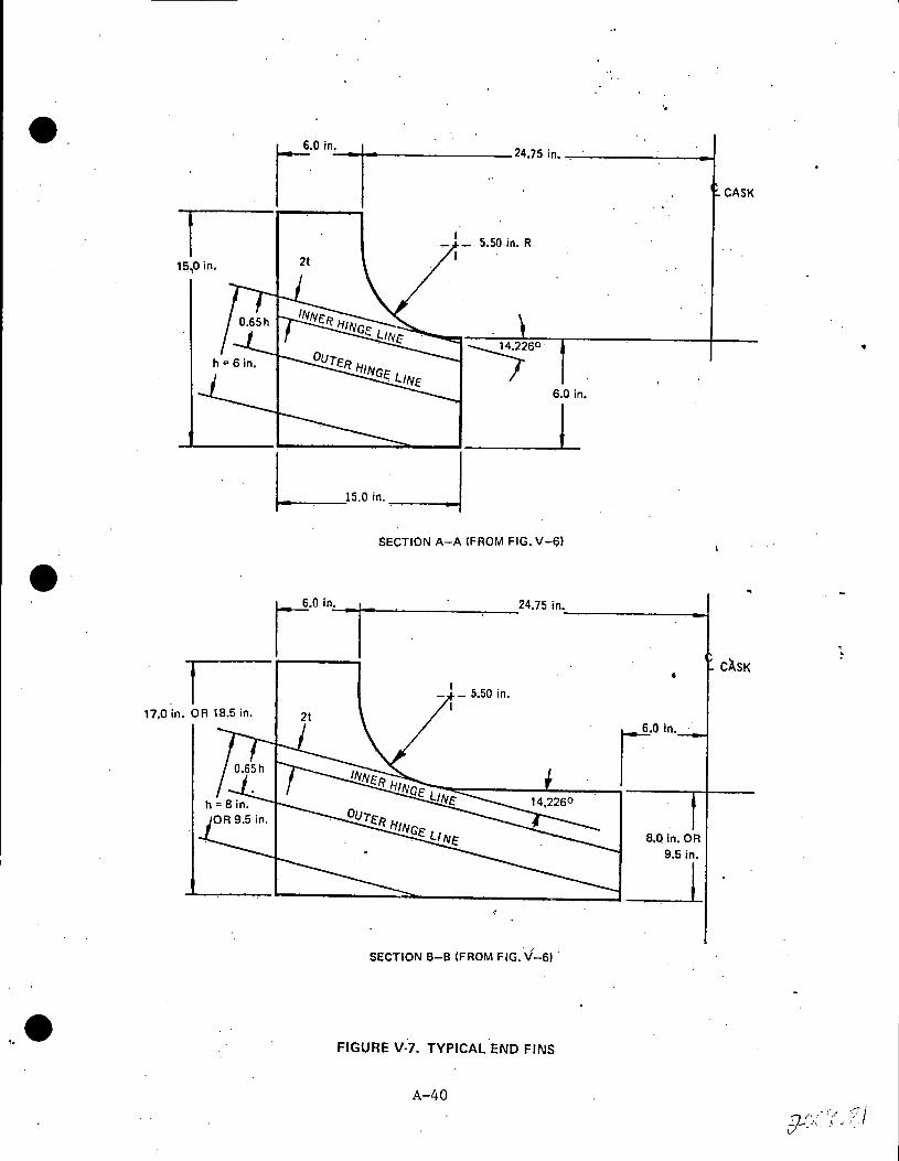
The hinge closest to the cask (Figure V-7) was assumed to form at two
times the fin thickness away from the surface. The hinge farthest
away from th~ cask was assumed to form at 0.65 times the fin height
away from the cask surface. These two values are based on measure
ments of the actual test fin profiles. The effective length of the
fin hinge lines (see figure V-7) is taken as
L + 21 ( inner outer) 3
The average deceleration is defined in terms of drop height divided by
deformation distance, (H/o). For the analysis of the closure~flange
and bolting, twice the value of the average deceleration was used due
to the close proximity of the flange to the point of impact. In the
corner drop both long and short fins deform to absorb energy.
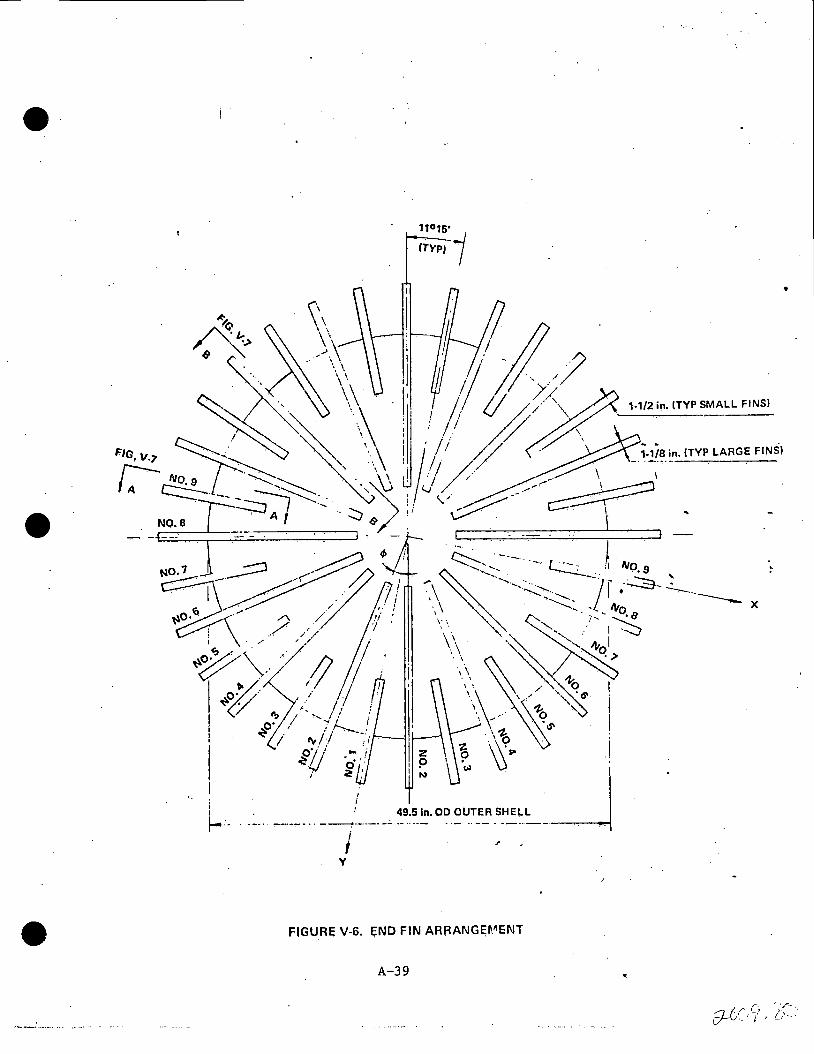
Assuming. th~ cask strikes directly over small fin 111 (see Figure V-6), the
first fins to contact the surface will be large fins 112. Further assuming
that the total angul~r rot_ation, 9, of the hinge lines on each of the fins
numbered 2 is only slightly less than the 1.5 rr radian maximum, then the
correlation curve of 9 versus percent deformation indicates these fins <
collapse to approximately 65 percent of their original height. This is
the maximum fin deflection and hence the cask deceleration distance. All
other fins will bend to a lesser extent since they· are further removed
from the point of impact. The deformation, o, of any fin may be des
cribed as follows:
A-37
•

FIN N0.1 (MAKES INITIAi,. CONTACT WITH SURFACE)
. . I
·. .· . . · ~ .· !ASSUMED AT . __._- · GEOMETRIC.r<
. . · . t C.G.OFCASK
14.4l258°
\.
\ '
\ \
FIGVRI; V-5. ORIENTATION FOR CORNER DRQP
A-38
...
SEE FIG, V-6 FOR FIN ORIEl\ilTATION
•
•
i .
FIGURE V-6. END FIN ARRANGEll.~ENT
A-39 •
e.
I 1e;,o in.
.I
,.O ;,_, •-t-1-· ---24,75 in.
5.50 in. R
6.0 in.
I SECTION A-A (FROM FIG. V-f?)
~-°'' .... · _,.,-rl ... .___,__ ____ .,-_24.75 in.
8,0 in. OR
9.5 in.
_.___-~----J_J ' /
SECTION B-B (FROM FIG. V-6) .
FIGURE V-7. TYPICAL END FINS
A-40
CASK
CASK ' .
•
'.'"! (• ,· 1",/ ·~1·· . .:_1-· :., . fi' •. ,·.' v - . ~

e·
..
Bottom End
Top End
Bottom End
Top End
·I i
I
I ~ is the angular location of the fin referenced from small fin
No. 1 (Figure V-6)
The energy absorbed in double fin bending is described by the following:
E = M 9 p
E :;: 2 (crHL t 9) 1/2 in.-kips
Where:
crH = Hinge stress of material,
L = Hinge length, in.
t = fin thickness, inc.
9 = Total angular rotation of
ksi
hinges, radians.
Fins Nos. 1 through 5 are the most effective in absorbing energy. Fins
No. 6 and beyond impact the surface at an angle greater than 10 degrees
therefore, only a single hinge is assumed to form. The foll_owing tables
~how the parameters used in the computations for the bottom end and top
end fin corner drop analyses:
. "
A.-41 I,'"'·~ .i. \ 7- ..
•

..
As stated previously, the values of 9 are obtained from the correlation
of fin bending test data. ·
The energy absorbed by the fins must be equal to the cask kinetic energy.
The cask kinetic energy at the moment o~ impact is 50,400 in.-kips. The
following table shows the energy absorbed by the fins for each end of
the cask as we~l.as the cask average decelera~ion based on "H-over-Delta."
A-42 "l 1(J· /\ l): \.:·· :;:: ol--C tJ I , ·-· " .
' --..... ·-:---~ .. -....------ .. ,.._, .... -·-···-··. - . --- -- ... - . ..
9· 3
..
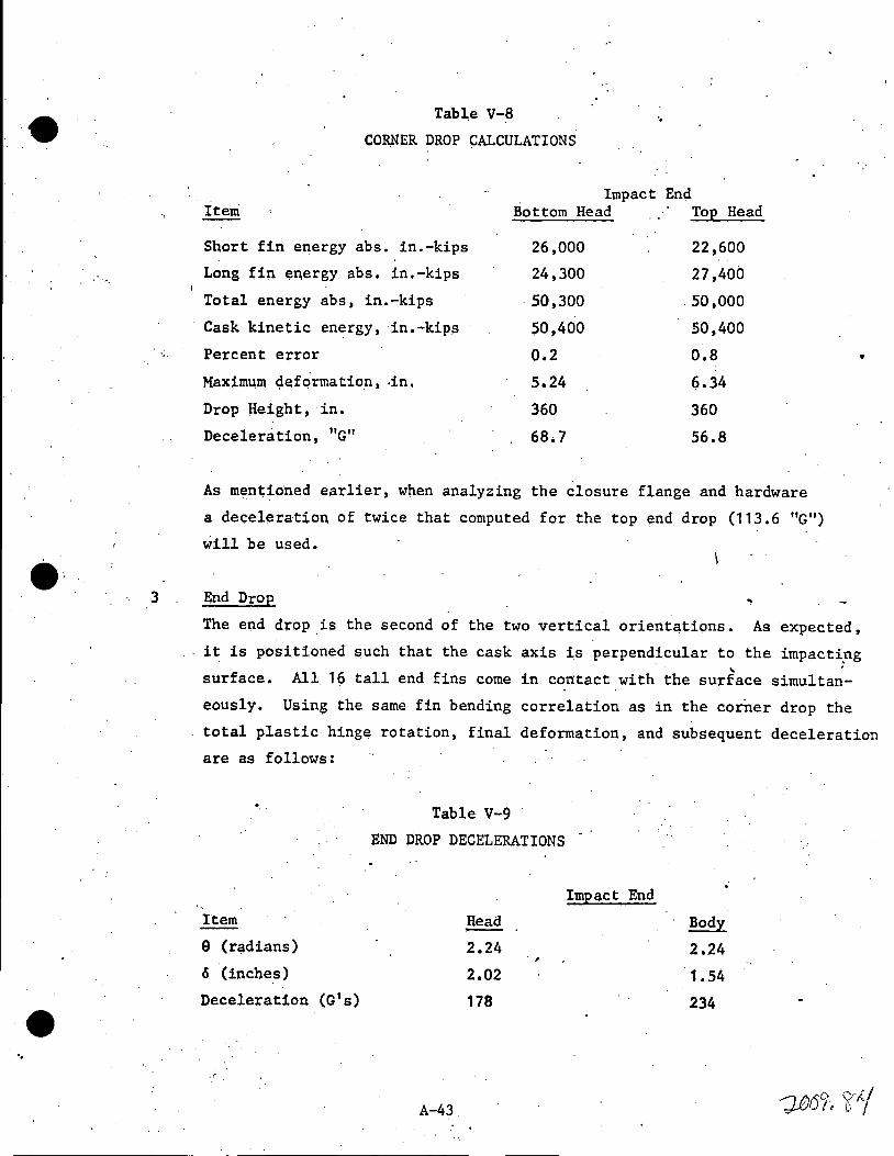
Tabl,e V-8
CORNER DROP CALCULATIONS
Iteni
Short fin energy abs. in.-kips
Long tiµ energy abs. in.-kips
Total energy abs, in.-kips
Cask kinetic energy, in.-kips
Percent error
Maximum c;lefqrmation, .in.
Drop Height, in.
Deceleration, "G"
Impact End Bottom Head Top Head
26,000
24,300
. 50,300
.:m ,4oo 0.2
5.24
360
68.7
22,600
27,400
. 50 ,000
50,400
0.8
Q.34
360
56.8
As mEmtioned earlier, when analyzing the closure flange and hardware
a deceleration of twice that computed for the top end drop (113.6 "G")
will be used.
End Drop
•
The ep.d drop is the second of the two vertical orientations. As expected,
it is positioned such that the cask axis is perpendicular to the impact~ng ' .
surface. All. 19 tall end fins come in contact with the surface simultan-
eously. Using the same fin bending correlation as in the corner drop the
total plastic hinge rotation, final deformation, and subsequent deceleration
are as fallows:
Item
9 (radians)
6 (inches)
Deceleration (G's)
.:"
Table V-9
END DROP DECELERATIONS
A-43
Head
2.24
2.02
178
.,
Impact End
Body
2.24 · 1. 54
234

-· .,
It should be noted that only the 16.talier fins crush sin~e the deforma-
tion distance is less than'the difference in fin heights. The deceleration
diffe~en¢e · (178 · V'er~us 234) is due to the taller ·uns (9 .5 in. versus · '' : ·
8 in.) on the closure end.
·4 Side Drop
As previously mentioned, six side orientations were analyzed under the I
30-foot drop criterion. These six positions are shown by t~e circled
numbers on Figure V-7. lllli>ac'.t protect;lon :f,s provided by a number of
structural members depending on orien~ation. The principal structures •
are four. heavy rings arranged in pairs a~ either end of the body. A
finned valve box is nested between each of the two pairs. of impact ri~gs.
~ 90-degree arc ring is111ounted on the cask boqy midway between the ·
valve boxes but on the opposite side. These structures are shown on
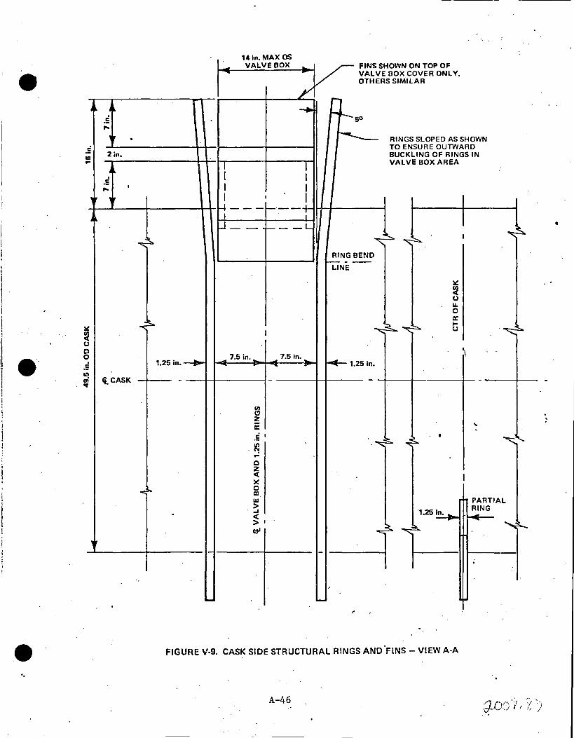
Figures V-8 and V-9.
Energy .absorption cqmputat;i.ons ut:f,lize the san;ie correlation employed in I
the vertical drop analyses. As shown :f,.n Figu,re V-8 the structural rings
and fins were a5sµmed to form two hinges with the hinge closes~ to the
caek forming at tw() times the fin thickness away frqm the cask surface.
The second hinge farmed at 0.65 times the fi~ height away from the cask , .. surface. The effective hinge length of th~ circular structural rings
·W'lS computed as follows:
L 2 lo+ Li = 3 · eff.
where: Lo = length of outer hinge line
Li = lengt;h of inner hinge line (See Figure v.,..a)
This is based on the fact that the outer hinge absorbs approkimately
two.;..thirds 'of the energy and· the i~ller hinge absorbs the remaining
Otle-thJ,J;'d • Thi's is consistent w,:f,.th that used for the corne.r drop
analysis.
A-44
,.
/) f))Jf'.,/ y /~ ifvl/ f r u. ~·

•·.
..
18.06 In.
2.0 In.
t 0.6511
t
2t
t
• '
/
15.7 in. --1.,_..l~ ... 11---
1.25 in. THK RINGS AT VAL VE BOXES (ti
. SYM ABT fl
©
A=i .
ALL MATERIAL TYPE 216SS EXCEPT AS NOTED
INNER HINGE LINE
1900 OUTER HINGE LINE
~-J 1-1/4 in. THK PARTIAL RING AT CTR OF CASK IOOoARCI
FIGURE V·S. STRUCT RING, FIN, AND VALVE BOX ARRANGEMENT
A-.45
•
· . .
e·
..
, ..
.5 UI ...
..
~
~ u 0 0 c!
...
•Ir
... .5 ,.. '. . 2 in.
, .. .5 ,.. I
'"
-c
ft. CASK
!!I.
141n MAX OS - VALVE BOX v FINS SHOWN ON TOP OF .... - VALVE BOX COVER ONLY.
OTHERS SIMILAR
,J/ I
r-1 __. .... ,__50
r-.__ RINGS SLOPED AS SHOWN TO ENSURE OUTWARD BUCKLING OF RINGS IN
I I VALVE BOX AREA
I I I I I I I ~---'-·--+
I . I u __ .__ __ L
~ I
RING BEND ,.___ - --
LINE.
~
~ u u. 0 a:
~ I-
I u ::,..
_ 7.5 in .• _ 7.5 in .• '\ 1.25in,_....,. ~ . .... v ~1.25in.
- - - - '
Vol Cl z a: .. . . 5 I ~ ·~ • '-.
. iq ... 0 z < I x 0 ID w PARTIAL > RING _,
·1.25~ . < ->• -
~ e:tl ~ ~
,_ - - . ,
- -FIGURE V-9. CASK SIDE STRUCTURAL RINGS AND °FINS - VIEW A-A
A-46 /} r· !"\ <r ·-:i ·:. \f-·J,__ .. I I /J )
' '
•

..
Referring to Figure V-8, the following is a listing of the six side
orientations and their respective energy ab~orbing members:!
Table V-10
ENERGY ABSORBING MEMBERS
Orientation
oo
I Ener~y Absorbing Member I Structural Rings, valve 1Box Fins
20° (valve box corner)
45°
I J 90°
1"35°
180°
Partial Ring
Partial Ring -
The following table summarizes the 0° side drop calculation parameters:
: .4.1 0° Orientation
This is a direct drop on the valve boxes. Energy is absorbed by defor
mation of the four structural rings and the valve box lid fins. As can
be seen in Figure V-9 structural rings are angled outward from the valve " box (5 degrees). This angle will cause the fins to collapse away from
the box in an unobstructed direction. The lid fins are inclined from the
vertical hence they undergo various angular rotations depending on their
location. Fin pairs 1, 2 and 3 strike the surface at less than 10 degrees
hence they form a double hinge. Fin pairs 4 through 7 are inclined at . -an angle greater than 10 degrees and only fail in single hinge bending.
The energy absorbed by the bending of a 216 SST fin or ring is given by:
E =
where:
L e
t
9
551 t2a in.-kips e
= = ""
effective 'h.ingle length, in.
fin thickness, in.
hinge rotation, radians
A-47
(5. 2)
•

i J ! i
l l
I ':
e·
-..
Fin No.
1
2
3
4
5
6
7
Struc.
Rings
For single hinges 8 -1 y
= cos . (h - 2t )
I where:
1'' .Y = y
h =
ei = 0 =
FIGURE V-10. SINGLE HINGE
- e i
(h - 2t) cos e . 1
fin height, in.
fin inclination,
fin deformation,
(5-3)
0
rad
in.
For double hinges e is derived from the fin bending correlation curves.
Table V-11 oo ORIENTATION PARAMETERS
Fin No. of h, 0i o, (h-2t), Y, Nq_. of e' thk,in. Fins in. deg in. o/h in. in. hinges rad
9/16 1 7.0 0 3.3 .0.472 2 3.78
9/16 2 7.02 4 3.3 0.470 2 3.77
9/16 2 7.07 8 3.3 0.467 2 3.76
9/16 2 7 .15 12 3.3 6.025 2.59 1 . 0.916
9/16 2 7.28 16 3.3 6 .15 2.62 1 0.853
9/16 2 7.45 20 3.3 . 6. 325 2.64 1 0.791
3/4 2 7.90 24.2 1.55 6.40 4.29 1 0·.413
1-1/4 4 J6 5· 3.3 0.206 2· 2.35 .-r
,,
•
' ~
The resulting cask deceleration is:
"G" 360 109 = = 3.3
A-48 d-J:V' 0 . ·.;, '( ')'J l ; lj t.

/
.4.2 20° Orientation . e This side orientation has th_e _impact point directly on the corner of the
valve box lid. As in the previous case the cask kinetic energy is ab
sorbed by the structural rings and the box fins. The energy absorbed is
computed using equations 5. 2 and 5. 3 as before. The. following table
gives the fin bending parameters:
~~ ~ -
·Table V-12
20° ORIENTATION PARAHETERS
Fin Fin No. of h, Si 0' (h-2t)' Y, No. of No. thk,in. Fins . in. deg in • o/h in. in. hinges
2 9/16 1 7.02 17. 1 0.5 5.895 5.13 1
3 9/16 1 7.07 13. 1 1.5 5.945 4.28 1
4 9/16 1 7 .15 9 .1 2.6 0.364 2
5 9/16 1 7.28 5. 1 3.6 0.494 2
6 9/16 1 7.45 1..1 4.8 0.644 2
7 3/4 1 7.90 3 •. 1 4.0 0.506 2
8 3/4 1 7 .16 7.3 2.7 0.377 2
9 3/4 1 7.03 11..4 1.45 5.53 3.97 1
10 9/16 1 6.94 15.6 0.25 5.815 5.35 1
Struct.1-1 /2 4 18.95 5 5 .1 0.269 ... 2
Ring
The
,4.3
•
resulting cask deceleration is:
. "G" 360 70.6 = = 5.1
45° Orientation
This side ·orientation places the point of impact directly on·the valve
~ ... bO·x side ~as tings. As in the two previous cases, the cask energy is
dissipated by the deformation of structural rings and valve box fins.
Formulas 5.2 and 5.3 describe this energy absorption. The following
table gives the calculational parameters.
e' rad
0.216
0.537
3.27
3.89
4.56
3.95
3.33
0.571
0.129 '
2.75
A-49 ')(lJO] I 7 () -·~-------···". _;;__ ___ _____: ____ .::_:___=::_::~'-'-.__:.__:_: _ _:::··•'....::··.::·•:.:::·-·-:._::··::_.:-•·•=· :__:· ·-...==-·=··· =·=-·=····=· =·· =·=-·=·=····=···~· -~·· ~· -~· ~· ~===·· ·e·--·· ·····--·
•
e·
..
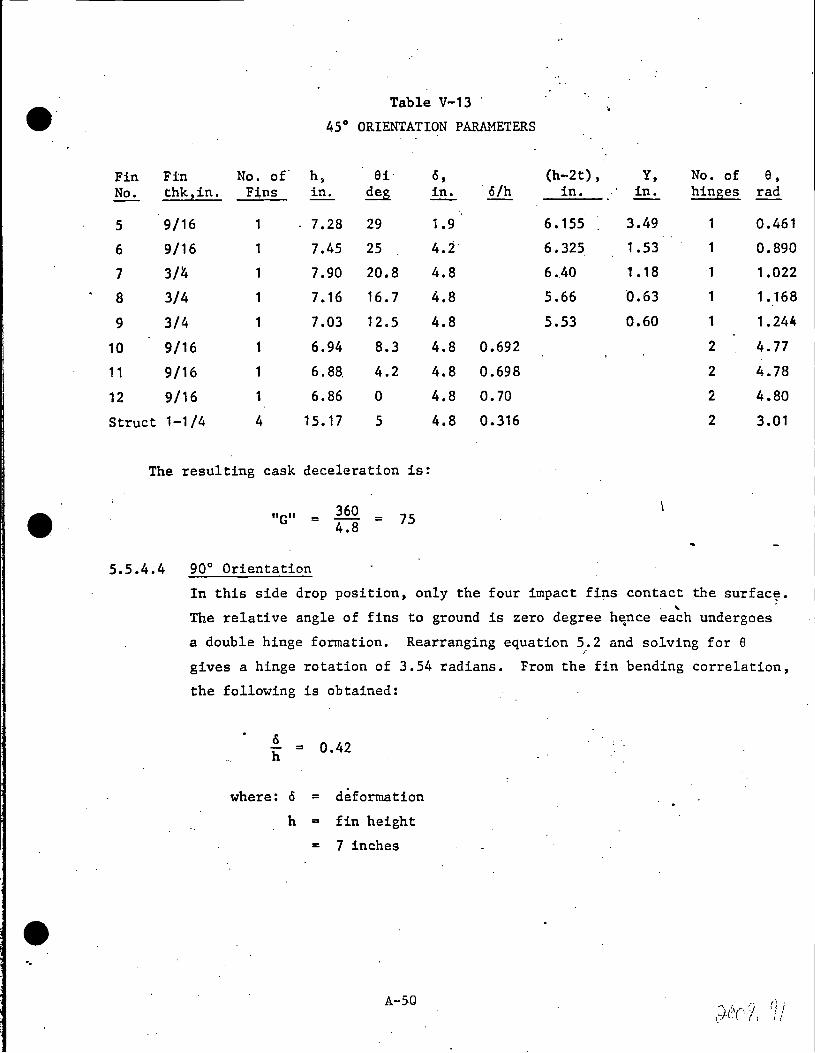
Table V-13 ·
45° ORIENTATION PARAMETERS
Fin Fin No. of' h, 6i o, (h-2t), Y, No. of 8, No. thk,in. F:tns in. deg in. · o/h in. in. hinges rad
5 9/16 1 7.28 29 1.9 6.155 3.49 1 0.461
6 9/16 1 7.45 25 4.i· 6.325 1.53 1 0.890
7 3/'4 1 7.90 20.8 4.8 6 •. 40 1.18 ·1 1.022
8 3/4 1 7.16 16.7 4.8 5.66 0.63 1 1.168
9 3/4 1 7.03 12 .5 4.8 5.53 0.60 1 1.244
10 9/16 1 6.94 8.3 4.8 0.692 2 4. 77
11 9/16 1 6.88. 4.2 4.8 0.698 2 4.78
12 9/16 1 6.86 0 4.8 o. 70 2 4.80
Struct 1-1/4 4 15.17 5 4.8 0.316 2 3.01
The resulting cask deceleration is:
"G" =
5.5.4.4 90° Orientation
360 4.8 = 75
In this side drop position, only the four impact fins contact the surfac~ • ...
The relative angle of fins to ground is zero degree h~nce each undergoes
a double hinge formation. Rearranging equation 5.2 and solving for 8 /'
gives a hinge rotation of 3.54 radians. From the fin bending correlation,
the following is obtained:
0 h = 0.42
where: o = deformation
h = fin height
'"' 7 inches
A-SO
..
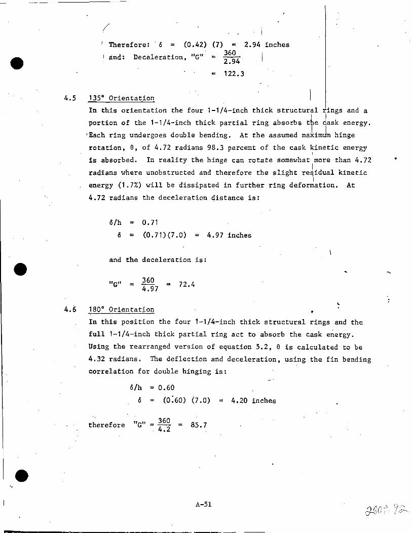
/ 1 Therefore: · o = (0.42) (7) m 2.94 inches
and: Deceleration, "G"
4.5 135° Orientation
= 360 2.94
= 122. 3
In this orientation the four 1-1/4-inch
portion of the 1-1/4-inch thick partial
•Each ring undergoes double bending.
thick structural rings and a
ring absorbs tte 1ask energy.
At the assumed maximum hinge
rotation, e, of 4.72 radians 98.3 percent of the cask kinetic energy '
is absorbed. In reality the hinge can rotate somewhat more than 4.72
radians where unobstructed and therefore the slight re~idual kinetic I
energy (1.7%) will be dissipated in further ring deformation. At
4.72 radians the deceleration qistance is:
o/h = 0.11
o = (0.71)(7.0) = 4.97 inches
and the deceleration is:
"G" 360 = = 4.97 72.4
4.6 180° Orientation
In this position the four 1-1/4-inch thick structural rings and the
full 1-1/4-inch thick partial ring act to absorb the cask energy.
Using the rearranged version of equation 5.2, e is calculated to be
4.32 radians. The deflection and deceleration, using the fin bending
correlation for double hinging is:
o/h = 0.60
0 = co:6o) (7 .O) = 4.20 inches
therefore "G" 360 85.7 =-- =
4.2
A-51
-----------------------------------
•

..
5
/
Deceleration Summary
Table iV-14 sununarizes the deceleration values for the two vertical
·six side drop orientations. The table also indicates that ~he cask
'kinetic energy has been effectively dissipated in each caseJ The . I
maximum end and side decelerations, 234 and 122.3 "G's" will be
used to evaluate the stresses in the cask contents. The 0° lside i I
orientation deceleration, 109 "G" will be doubled when evaluating
tbe stress in the valve box structure. The top corner d}op I deceleration, 56.8 "G" will be doubled when evaluating the closure
·flange. i
Table V-14
30-FOOT DROP DECELERATION
SUMMARY
Orientation ~,in-k E ABS,in-k %ERROR* IS
in.
I -0° Side 50400 51160 1.5 3.3
20° Side 50600 0.4 5 .1 ...
45° Side 50220 -0.36 4.8
90° Side ·50400 0 2.94 ...
135° Side 49560 -1.7 4.97
180° Side
Top End
Bottom End
Top Corner
Bottom Corner
50400
50400
50400
SOOOQ
50300
* Negative Sign Indicates Residual Kinetic Energy •
A-52
0 4.20
0 2.02
0 1.54
-o .. 8 6.34
-0.2 5.24
•
"G"
109
70. 6-
75
122.3
72.4
85.7
178
234
56.8
68.7

S E C T I 0 N B

9· SECTION I
OPERATING INSTRUCTIOns
GENERAL ELECTRIC'S IF-300 IRRADIATED FUEL SHIPPING CONTAINER AND
TRANSPORT SYSTEM
Introduction
This manual h~s been prepared as an instruction in the proper use and
operation of t~e Genera1 Electric IF-300 Irradiated Nuclear Fuel Shipping
Container (cask) and its associated Transport System. The manual consists
of a description -0f fh~-system, detailed step-by-step operating procedures~ ·":· ..
Every effort has been mace to present detailed loading and unloading
procedu(es that would be applicable at.any reactor site or reprocessing
plant, but the differences between plants and their handling equipmer.t make
it impossible to provide universally applicable procedures. The personne1 at
each site should provide themselves \tlithadetailed handling procedure, based
on the material in this manual, that will properly take into account the
arrangement of, and the equipment avail~ble at that site.
B-1

T ,.
e·. l.
Section I
Description' of the G.E. IF-300 Cask and Equipment
1 . 1 Cask
The cask (Figure I) consists of the cask body and an interchangeable
head or closure. The body is made up of four layers of material: an
outer corrogated stainless steel layer in two sections attached to the
crash fins, a second layer of stainless steel, valve boxes, and flanges,
a third layer of depleted metalic uranium, and a fourth or inner layer ·
of· stainless steel (also attached to the flanges). The outer layer acts
as a container for a 5" water annulus (n~utron shield) between the upper,
center and lower fins, the second layer acts as a puncture shield and cover
for the midd1e layer. The middle layer is the cask's radiation or biological \ .
contents and serves as the pressure vessel for the contained shipment and
its surrounding water.
The cask is supplied with,two closure heads, one with a deeper cavity than
the other. The shallow head is intended for use wi.th PWR type fuels, which
are shorter than BWR type fuels. The longer head effectively lengthens
the cask when it is used, and thus provides the required cavity space for.
BWR type fue 1 s ..
During shipment, the fuel assemblies are held in place and separ~ted from
each other by interchangeable 11 bas'kets". These baskets serve several
functions: they locate the fuel with respect to the casks inner shell so
as to provide a water annulus, which acts as a neutron shield; they provide
B...:2
'I (':·,(''ii.' '/-· r/ (/- '/i,• I .<'

~·_---· ...
. ' ·--'"--
VALVE BOX
STAINLESS STEEL
IMPACT flNS SHELLS
I I . . CLOSURE HEAD
IMPACT FINS IF 300 SPEN T FUEL SHIPPING
er"'e"•' A ..... - ···-VELECTFllC
Fig .I.
CASK
I •• t-·-···
. '
e: structural support to th.e fuel during shipment; and they provide criticality
control. Because the baskets are designed to be interchangeable, the cask
can accommodate al1 the types of PWR and BWR reactor fuels currently in
·.e
use by merely changing baskets and associated fuel spacers. Table I
is intended to be used as an index of the appropriate basket and fuel spacers
used with each of the current fuels. The cask will be shipped from the
reprocessing plant to the reactor site ~ith the appropriate basket and
spa~ers installed.
The cask is equipped with two valve boxes that contain the drain valve
11 011, vent valve 1:v 11
, and relief valves 11 R11 to the inner cavity. The valve
box at the top of the cask contains a ~lobe valve equipped with a valved
Snap-Tite coupling and a dust cap, the vent valve 11 V11, and the safety·
valve 11 R11, which is set to operate at 350 PSIG pressure. The lower Val~~
box contains the drain valve 11 011, a glcte valve equipped with a Snap-Tite
coupling containing a spring loaded shut-off valve, and a dust cap. Access
to the valves requires removal of valve box covers. The covers are
heavy, and must be removed when the cask is in the horizontal position on
the skid ~ith mechanical assistance.
·rwo centrally located valve boxes each contain the drain, vent and
relief valves-for the outer shell containing the outer neutron shield •.
Each compartment, upper and lower, contains approximately one ton of
water and anti-freeze. This solution will be semi-permanent, drained only
as necessary for cask maintenance at the recovery plant.
B-4
flXED ENCL. OSURE
e·
MOVEABLE COO
"""
lll\IG DUCT
Tll'l'ING CR ADLE
;,
""' DUCT Fill:[;) CCCLIII;~
.l'ECUlloOAl\oT (NGI COOLING <.NE. BLOWtR
... YST£M
100 ' TOl\I CAPACITY HAT CAR
IF 300 SP SHOWl\l 11\1 NO~NT FUEL SHI .. MAL, RAIL TR PPING CASK U1SPORT CO'-lfl
GE HER AL ~. GUAAT•Olll
W ElECTllC
/:"15 ).. .
-:;:""~
~.-
Go
,•
14.4~i;·
1 ' · 1-o.f, "'T I
7,21~
'92 79
e·
•
{
\
64 in.
49,748 #
24,874 6,220
80 68
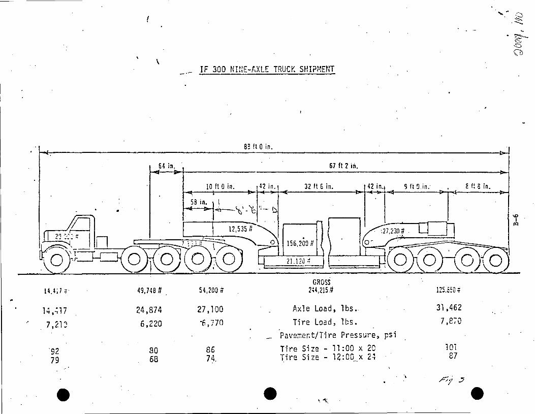
IF 300 NINE-AXLE TRUC~ SHIPMENT
82 !t 0 in.
67 ft 2 in.
IO ft Qin. 4 2 in. I 32 ft 6 in. 42 in.
58 in. i ; \' 't: <:'!- - ·~ ·~ --· 1"
. 156,2Cn #
21. l ZJ :t
GROSS 54,200;; 2~4.215 !I
27 t 100 Axle Load, lbs •.
•6 ~ 770 Tire Load, lbs. Pav2rr:ent/Tire Pressur-e,
86 Tire Size - 11 :00 x 2C 74. Tire Size 14: oo_ __ x ,. ~ - t.~
e •. "'\ ..
... . ~ ""'.)' ~ (b
9 ft a. in. E t; e in.
\0 I
p'.:I
pc;~;;.~.; """'•"-•l.I 't
31,462
7,870
psi 1 Oi 87
' ~1 .:J
e
: I : lj . ·. t !
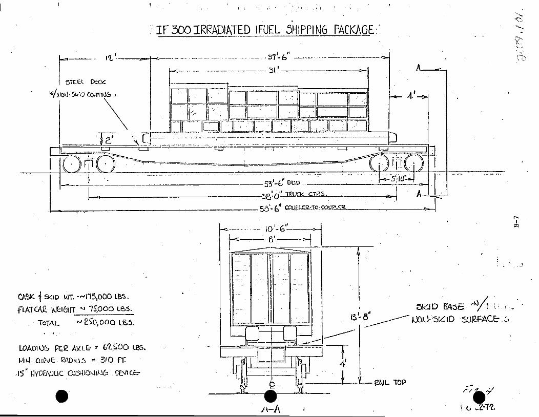
. ::·IF 300 IRRADIATsD !FUEL 5HIPPI N6. PACKAGE:.
I •' . -----·-··· ---···---- --·· . ··-···-- ··- -· ····- .. 31-b ----·······-- ----··------------··
K··-· .... ..... . -·-------. -······ ·-·-- ·-···· 31 I--~--- A_...:_.
.I
- +-~----.-·-····-· ·-··-·· .. ······-·· ___ ··· =:ig:;~-=..CTu.;:_1?5=:..,___,c__-_·· _···_· _· .--F!--i A----'-.;~····_.- -----
- _ $:i'- bu cg,J.£!..,kl.?.·_IQ~OU?,-='-t;:==-R--------~
C/\~'t.. 1 SK10 wT. -""1151000 LB~. fLATCt\l2. \1Jt:l611T ...i 15,0CO te:,s.
.. TcTAL t>J 2S'o, 000 L~!>.
LOADIUb Pt:l2 A'iL& : ~'l,SOO LBS.
M1i.J. CulivE. 1(1AD105 ~ 310 FT ~
-15 1-NDl?J\'.JLIC O.lSt-\10"11~ . CE.VI Cf:-
e·
____ :_ 1: i
.. ii - -- ~ ·: .
I -·
/\-A
... ·; .. J
,,IJ /, \ : . . -/ 1. ·-··. ·-

When equipped with a basket, closure head, and spacers, and loaded with
fuel elements, the cask weighs approximately 140,000 lbs. In its longest
configuration, it is approximately 17' 5" long and has an overall diameter
of approximately 5' 2" •
. 1.2 Steel Skid Frame
The cask is transported on a steel skid frame equipped with integral fuel
tanks and suitable members to support and hold the cask in place.
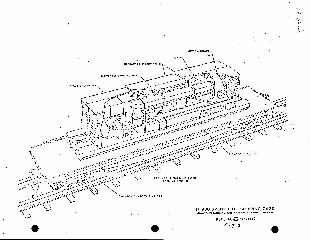
The cask a~d its transport system will be shipped between the reprocessing
plant and the reactor site by rail on a flat car designed for the system,
{~ig. 2). If the reactor site does not have railroad facilities, the ' - ........... ••. -~·."·
....... I,, llt:
nearest railroad siding (Fig. 3). Because of the combined weight of the
system, the possibilities of road transit will be severly restricted,
and every effort should be made to limit road transit. In those cases
requiring over-the-highway operation, truck wheels and a truck tractor
are attached to the skid at the nearest siding. As Figure 3 shows, the
skid is designed to accommodate special wheel assemblies having built-in
self-jacking capabilities. When the loaded cask returns to the railroad
siding from the reactor site~ the wheel assemblies are removed prior to
shipment. The r·ailroad siding will have a roll-on/roll-off ramp for
placement ·or removal of the transport system.
B-8

9 l.3 Cask Hoods and Equipment
The skid frame is equipped with three-section aluminum enclosure, two
sections of which are movable ahd telescope over the third section.
The enclosure, together with the equipment enclosed, is shown in Figure 2.
The fixed or equipment hood contains most of the transport system
equipment, including the cooling fans, the diesel engines used to drive
the fans, and a part of the secondary cooling ducts. The telescoping
hoods, in addition to covering the cask, also ~nclose the remainder of the
secondary cooling ducts and the nozzles used to direct the air to the
cask. The fans were selected so that each, alone, is capable of supplying
sufficient cooling air to hold the cask at proper equilibrium temperature.
Norrn~lly, hoth f~n~ are st~r+ed at the r~actor site ~nd function for a
minimum of 240 hours without attention; if one fan should fail enroute,
the second will provide ample cooling to protect the fuel elements.
Because of restricted power plant clearances, the overall enclosure height
has been held to 13' 8'' above the rail when the transport system is mounted
orr its railroad car. Clearance dimensions are shown in Figure 4.
1.4 Cask Supports
The lower end of the cask rests in a tiltable socket when the cask is mounted
in position for transport. The socket is counterbalanced and will remain in
a horizontal position, facing upward, when the cask is not in the socket.
The socket journals are located eccentrically with respect to the longitudinal - .. ... . . . - -- - - ... ·-.
B-9

' 0 ••
B-10

~-·
r . (j ~· '
·~ L- ! : t
' . I : •...
- ...... ..:.. -<..-
i J I i I - -1
I- . I
' ! ·- t - - -
_L I. I ~
I I
.I ~ .· I
(:: :
I
i
. ,..ti
I I I I
·- I\' I 1
! \ I
I \
i I I \
l-- .. I : i
r- -, : i. L--l t- •• - -· I
I
I
,.
,n . . \ '7~:~y-.
. .. . \ I~·._
.....
.·
........_"'-- t:'H-' .-~. :..-:...._ ~ r~1." :r rAD
11 i --- ----- 65- '-------,
; -· I cj. \ L - - --:- - - ·-.
i-'-- 15· '
~J:J J!..::~::.<'.~_J~.;~TfJC cm .. \PN ]'( n- : "; .--: rJ-.~~'<
LlFTl 1.J G YOKE:-
c '

axis of the cask and, as the cask is lowered into the socket, the cask
will tip in the proper direction with respect to the skid frame. As the
ribs on the cask's head-end come in contact with the head-end support
saddle, the cask is pulled a short way out in the socket, thus providi~g
clearance for thermal expansion. The cask is held in place during
transit by rigidly pinning it to the skid frame saddle.
Lifting lug attachment points are provided on the cask between the two
upper impact or lifting rigns. The lifitng trunnions are pinned to the
cask with the same pins that anchor the cask to the skid (Fig. i. An
interferenc_e shield prevents attaching trunni'on until the anchor pins
are removed from the skid mounting.
1.5 Lifting Yoke
A special lifting yoke (Fi~ure 8) is provided to handle the cask at the
reprocessing plant and another at the reactor site. This yoke will be
shipped to the reactor site separately from the cask. It is d·es.igned to
be used with standard reactor site cranes. The lifting yoke· is attached
to the cask lifting trunnions between the two top impact rings. The
cables, provided for the purpose of removing and replacing the cask heads,
will be attached to the yoke.
l.6 Locks
e Access to the cask and secondary cooling system is 1 imited by adjustable
-combination padlocks. When the equipment is shi~ped from the reprocessing
B-12 I •' . ) (("'/ ' { 0 ( ·'
• 1',
plant, these locks will be set for a specific combination and the com
bination will be recorded. General Electric will transmit the combination
to the reactor site .
2. Safety Precaution~
This section of the operating manual is not intended as a set of safety rules
or to supplant the safety rules of the utility plant, but rather to serve
as a caution to the utility and reprocessing plant personnel that there are
inherent hazard~ common to the handling of any spent fuel cask. The cask
and all handling tools and equipment are massive and heavy. Many pinch-point .
hazards exist. A very slow swing of the suspended cask will contain a large
umount uf ~nt:~gy. Wldl~ beirig st:rviced, the cask is up;-ig:1t and 2~ght2en
feet high which constitutes a fall hazard. Improper rigging can cause a
cask or equipment drop. The surface of a loaded cask at equilibrium may be
uncomfortably hot. Improper placement of the closure can result in radiation
streaming when cask is lifted from the pool.
Because cf the above stated conditions, it is imperative that site personnel
be thoroughly familiar with the equip~ent and hazards and handling procedures,
and are equipped with site safety rules and safety equipment to perform all
phases of cask handling safely.
B-13

~3 •. Responsibility
The utility will be responsible for.the cask and loading operation from time
of delivery to the site and until the cask and rail car or interrnodal vehicle
is ready to dispatch.
The General Electric Company· will normally be responsible for the cask and
fuel upon sign off for dispatch.
·.;..
. . " . ·. ;·/) \~: . ";)..(,!() '{ ( v 1\
B-14

SECTION V
CASK HANDLING AT REACTOR SITE
·This procedure assumes the cask car has been delivered tCI the site air lock.
,. 1. ; Inspect car and transport system upon arrival at the reactor site.
If damage is evident, contact General Electric Company at the Fuel
Recovery Plant as to advisability of continued use of equipment.
· 2. Spot Car Under Equipment Hatch.
2.1 Secure outer air lock door and open inrier air lock door.
. .
2.2 Extend cable of capstan (car mover) and attach hook to corner of car.
2.3 Release car brake.
2.4 Move car slowly through inner air lock door until trunnions of cask are
located under crane hook when hook is at its south limit in the
~quipment hatch. This will be located experimentally during the first
time cask is at the site. Place index marks.on the rail o~ floor for
·future reference.
2.5 Set brake and place wheel thricks before and aft· of car.
3. Unloading Cask From Skid Frame
3.1 Open Hoods (Fig. 1)
3.1.1 Remove two retaining pins "A" on front corner of large hood.
B-15
·--~!: ''""

l
~
f ~·1 i ~ ~ --- ./ ...... I .,_ .\ : ,- ... , .
ffrVI --rp ... ....__ ..
f
..
,i
I I
"' .... 1' . . ..• I. l I
I
... __ .._.,.._. ... ________ .-...... ~. ~':\.-.:,.._ _____ \
9t-s:
~ I
;
\ "
' ...
~-D
~ 0 J
D a ~
e 3.1.2 Release six hood lock pins 11 C11, three on each side, by turning
.handles 11 811 90°M, raising to limit and turning handles into
retaining notches to hold pins in unlocked position.
3.T.3 Remove.two padlocks "D" securing lock handles (E). Raise the
handles to limit and turn them 90° into retainer to hold them open.
3.1 .4 Grasp operating levers 11 G11, one on each side of center hood, push
handle toward auxiliary equipment end (end B) of skid frame. Each
lever will rotate approximately 30° to lift hood onto rollers.
Continue push on levers until center hood telescopes over auxiliary
.equi-pment hood. Release levers to lower center hood off rollers.
3.l.5 Move large hood in like maoner until it is telescoped over equipment
hood.
3.1.6 Remove two snap-on air duct couplings 11 R11 on the upper air ducts,
one on· each side. (Fi9. 2)
3.1. 7 Raise the four duct lock pins 11 K11, two on each side, until pin
clears top of guide 11 L11, turn pin so it rests on the guide, retained
in open position.
3.1.8 Grasp the duct support tube 11 S11 and move the duct outward to limit.
3.2 Remove Valve Box Covers·
The cask cavity valve boxes are located between the upper and lower·
energy absorbing rings, on top of the cask when cask is in th~ horizontal
B-1.7
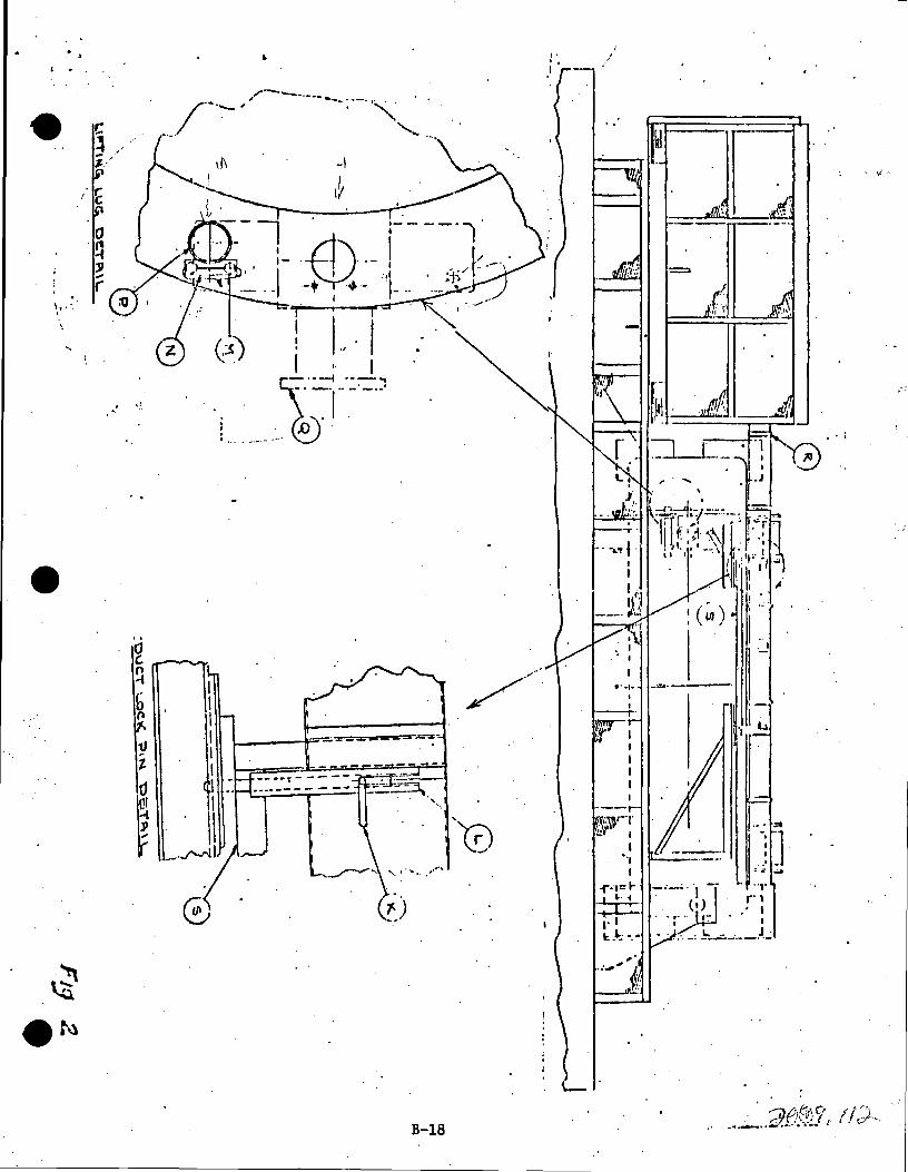
\,.· . .
,•
.. cJ (.
~ b " 11 t. 0
~
'
I I I I I I I I
. I\ _ . ...l'-"'l.I
. I
B-18
. ,
_/!.'!!.: . . ~;,·
.... , .. --·--· I
I ___,.
I ---r-_\".:\}rT
:..•. I
I ... I : .......
i"·v=I- -"-JJ· I .. r:·~· :!:[::: .. , ... (·~- .·:
1· I I J . l:.I.:: ·.- .... -. -= .h...::.--------
L- .
-i
,•
·. d. ,,
• • j
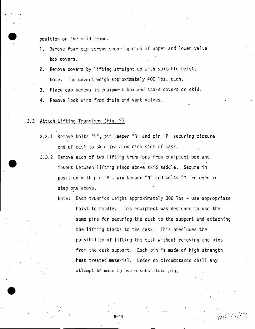
position on the skid frame.
l. Remove four cap screws securing each of upper and lower valve
box covers.
2. Remove cavers by lifting straight up with suitable hoist.
Note: The covers weigh approximately 400 lbs. each.
3. Place cap screws in equip~ent box and store covers on skid.
4. Remove lock wire from drain and vent valves.
3.3 Attach Lifting Trunnions (Fig. 2)
· 3.3. l Remove bolts 11 M11, pin keeper 11 N11 and pin 11 P11 securing closure
end of cask to skid frame on each side of cask.
3.3.2 Remove each of two lifting trunriions from equipment box and
fos-ert betv1een 1 ifting rings above skid saddle. Secure in
position with pin 11 P", pin keeper "N" and bolts 11 M11 removed in
step one above.
Note: Each trunnion weighs approximately 300 lbs - use appropriate
hoist to handle. This equipment was designed to use the
same pins for securing the cask to the· support and attaching
the lifting blocks to the cask. This precludes the
possibility of lifting the cask without removing the pins
from the cask support. Each pin is made of high strength
heat treated material. Under no circumstance shall any
attempt be made to use a substitute pin.
B-19

I ,
-------74c -·------~ 1 (~-1- -~ ~---~-· --~~;
j t I \L l_ I ,
i u·: :-.. 1& + ~ I I I • ;I, b DIA. . ! I I ::.~: J P!l l
: 1' I f - I I ; I
! , I . I
, .. I I . /·· I I ,... I
I I
' ; I r· ·! n, . . ,.ti -_ j ' ' ............_ i : · HU..0 CA6Li:"S r-·i I .
,, •. t : ...,,. : I~ I
i '. ~'. i : !
- - ,1.'' :.....-I .
. ! I
. I I
. r --\ I l I I I . I 1-
I \
1 , .
J_:- r--~
LJ
I I i I --1, 'i L--i ·-- - _,
11 - J --- -··-- 65 - . ------,
•• -?l}-'j. . ,9·
... I _, to/I .......,_.__
-· ~-h
n \ .+ i -i u ..
. . . \
\ ~
i -- . .,,,~1 \ '-t~~ -·-:
~JJ. !!~~~/ -~---~~-;~TfJC CO>- \PtJ..l'( Jf-'. · .... ""'.. rJ.SK .
I
. L1 Flll.J G YOKE:F11./ ,1-.,,
... - . ii"' .•
-~ .. ..
0 N. I
i:q
.
'
.~ .. !

e. 3.4 Attach Lifting Yoke to Crane Hook (Fig. 4)
The six inch diameter pin must be retracted to attach crane hook to yoke.
3.4.1 Attach short handle to the lock bolt- socket. Loosen lock bolt
(M-19) by turning counterclockwise until resistar.ce is felt.
3.4.2 Apply pin actuator socket to pin actuator shaft and turn shaft
clockwise until pin is fully retracted.
3.4.3 Lower the crane hook between the two channel sections so sister
hook center hole is aligned with yoke pin.
3.4.4 Turn the pin actuator shaft counterclockwise until the pin is· . fully inserted .
. 3 .. 4 .• 5 Tighten lock bolt by turning clochlise.
3.5 Attach Lifting Yoke to Cask
Assume car to be properly spotted and chocked.
3.5.1 Move crane hook/lifting yoke perpendicular to axial center
line of cask until yoke hooks are betw~en trunnions and top
of cask with open side of yoke hooks toward bottom of cask.·
3.5.2 Lower hook/yoke, guiding yoke hooks astraddle cask, until open
area of hook can accept trunnions.
3~5.3 Move crane hook/yoke laterally toward bottom of cask until·
yoke hooks are directly under trunnions~
3.5.4 Raise crane hook/yoke until yoke hooks have fully engaged
ea~h trunnion.
B.,-21

. -e
3.5.5 Stop lift and ascertain that yoke hooks are properly engaged
on each of two trunnions.
3.6 Raise Cask to Vertical Position
...
3.6.1 Check skid and cask to ascertain that there are no
encumbrances to rotation of cask from horizontal to vertical.
3.6.2 Check car b·r·ake and wheel chocks for proper placenient.
3.6.3 With load line of crane vertical (plumbL start lift of
,crane. As cask rotates from horizontal to vertical, move
crane laterally toward bottom of cask so as to keep the load
line plumb.
Note: If space in hatch way limits lateral travel of crane,
it may be necessary to stop lift and respot car so
the cask socket trunnions will move toward the center
of the equipment hatch. Change wheel.chock location
accordingly.
-3.6.4 Continue lif~ when cask approaches vertical (approximately 87°)
~top lateral travel until crane hook has full load of cask, this
will prevent rocking at top of arc.
3.6.5 Move cask to decontamination pad, set down on the pad •
3.6.6 Close the hoods on the cask car; if car is outside of building .
B,-22

-- 4. Prepare Cask to Loud
The cask has been flushed and cleaned at the reprocessing plant. Internal
inspection and flushing at the utility plant is opt.ional to the utility.
· 4.1 Wash exteridr of cask to remove road dirt~ Smear cask (monitor)
as directed by Health Physicist.
, 4.2 Attach closure head lifting ca~les located- in the equipment box,
secure pins with cotter keys.
4.3 Loosen all closure nuts until complete disengagement of nut thread
from the stud thread is assured. Leave all nuts in place in the
closure head sockets. (of BWR closure only). I
!
4 .4 Attach demi n H2o supply hose to snap-t ite fitting on.drain va 1 ve. 11 D11 s I
open valve "D".
4.5 Attach overflow hose to snap-tite fitting on vent valve "V", open
valve 11 V11• ·(An acceptable alternate is to use fuel pool water)
4.6 Fill cask with deminera]ized water through drain valve.
4.7 Close drain valve 11 011 and remove hose from snap-tite fitting.
B-23

4.9 Attach tag lines to yoke.
4.10 Move cask via pr~scribed routeto position directly over pool cask
pad; stop at pool rail to remove •section of rail. Replace rail before
lowering cask.
4.11 Orient yoke of cask in·accordance with available space in particular
facility to permit ease of yoke and closure removal.
4.li Place lights. ·View su~face onto which cask shall be set to ascertain
that surface is clear.
4.13 Lower cask-slowly to bottom of pool.
Note: The first time cask is being loaded, index marks ~ust
be made on both X & Y cr.ane travel so crane hook/yoke can be
returned to th~ exact position for replacing closure.
Also index cables indicating point when load transfers from
hook to pool floor and point at which yoke hooks clear bottom
of trunnions.
· 4.14 Stop down travel of hook/yoke when top of·yoke hooks clear
bottom of trunnions permitting disengagement.
4.15. Move crane laterally until yoke hooks are completely disengaged from
trunnions (approximately 10").
Note: The closure cables are still connected to the closure
and excessive lateral tra~el of the hook will tip the.ca~k ..
Cables must never come taut while moving laterally.
Note: Index mark cable at this elevation.
'"" Or')' t/ t / f 8·· . r/-\.1 ;~ . .
I
I
I

e.
. e
4.16 Raise crane hook/yoke until bottom of yoke hooks clear top of trunnions.
4.17 Move crane hook/yoke laterally back to center bver top of cask.
4rl8 Slowly lift crane hook/yoke. When closure cables become taut, the
·closure will start lifting off the cask. Closely observe cask for any
tendency to m6ve while closure ~s being lifted.
of 4.19 When closure is clear~ _ cask, raise crane hook/yoke and closure out of
the pool.
4.20 Inspect the Gray lock stainless steel gasket attached to the closure.
At this.point, the procedure may vary, depending upon the reactor site
arrangement. At some sites it may be necessary to release the main cr.ane hook
for other ~mrk. If such is necessary, the crane disengagement is performed
as a reverse of that described in 3.4. Otherwise, the main crane hook may
be left attached to the yoke with yoke and closure hanging in pool or above
floor. If it is necessary to set_yoke down, a pedestal must be provided
to set the closure on, thus preventing s. st gasket from being damaged.
5. Loading Cask
5.1 Obtain list of fuel assemblies to be loaded and transfer procedure and •
map (form ) for the fuel basket. ----5.2 Move fuel assemblies, one at a time, with fuel grapple from storage
rack to the cask .
5.3 Verify identity of assembly immediately after placing it in the basket.
~-25 (, I tr). "':'l__i\,.'l:I .,J . . f 0
1', cr•J,.,.11 1 r •
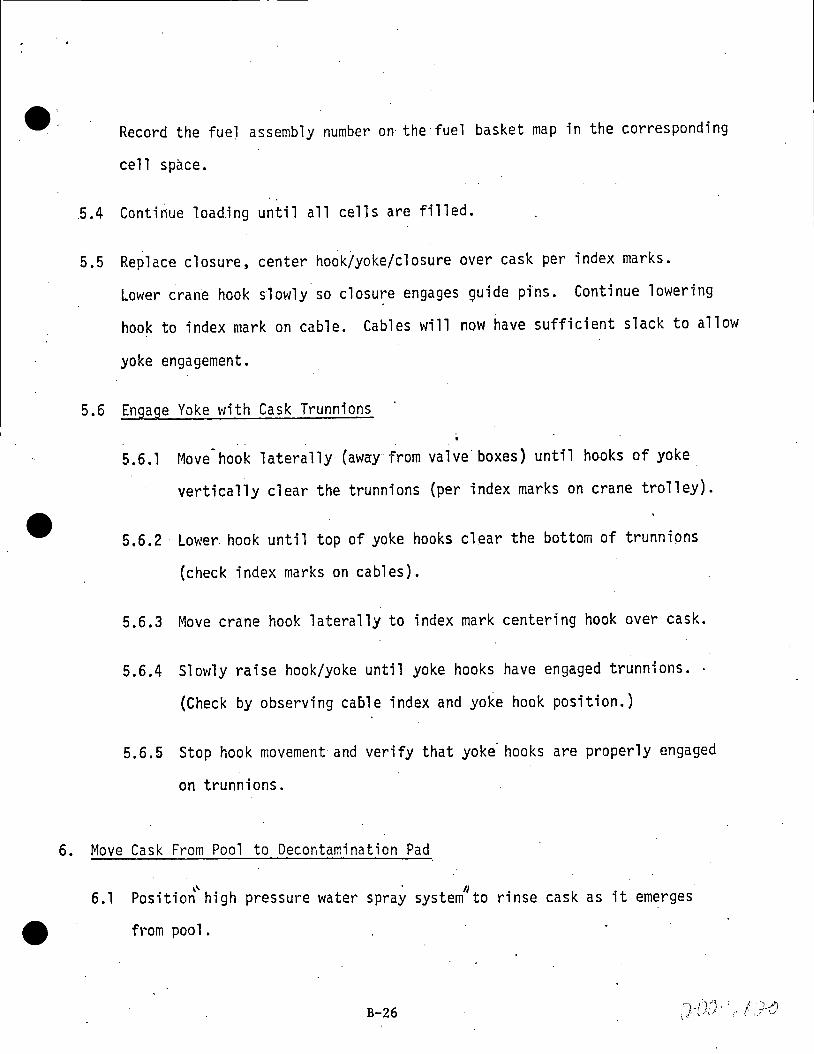
Record the fuel assembly number on the·fuel basket map in the corresponding
cell space .
. 5.4 Continue loading until all cells are filled.
5.5 Replace closure, center hook/yoke/closure over cask per index marks.
Lower crane hook slowly so closure engages guide pfns. Continue lowering
hook to index mark on cable. Cables will now have sufficient slack to allow
yoke engagement.
5.6 Engage Yoke with Cask Trunnions
. .
5.6.1 Move hook laterally· (awa:y from valve· boxes) until hooks of yoke
vertically clear the trunnions {per index marks on crane trolley).
5.6.2 · Lowe~ hook until top of yoke hooks clear the bottom of trunnions
{check index marks on cables).
5.6.3 Move crane hook laterally to index mark centering hook over cask.
5.6.4 Slowly raise hook/yoke until yoke hooks have engaged trun~ions.
(Check by observing caole index and yoke hook position.)
5.6.5 Stop hook movement and verify that yoke· hooks are properly engaged
on trunnions.
6. Move Cask From Pool to Decontamination Pad
6 .1 '' . II Position high pressure water spray system to rinse cask as it emerges
from pool.
B-26
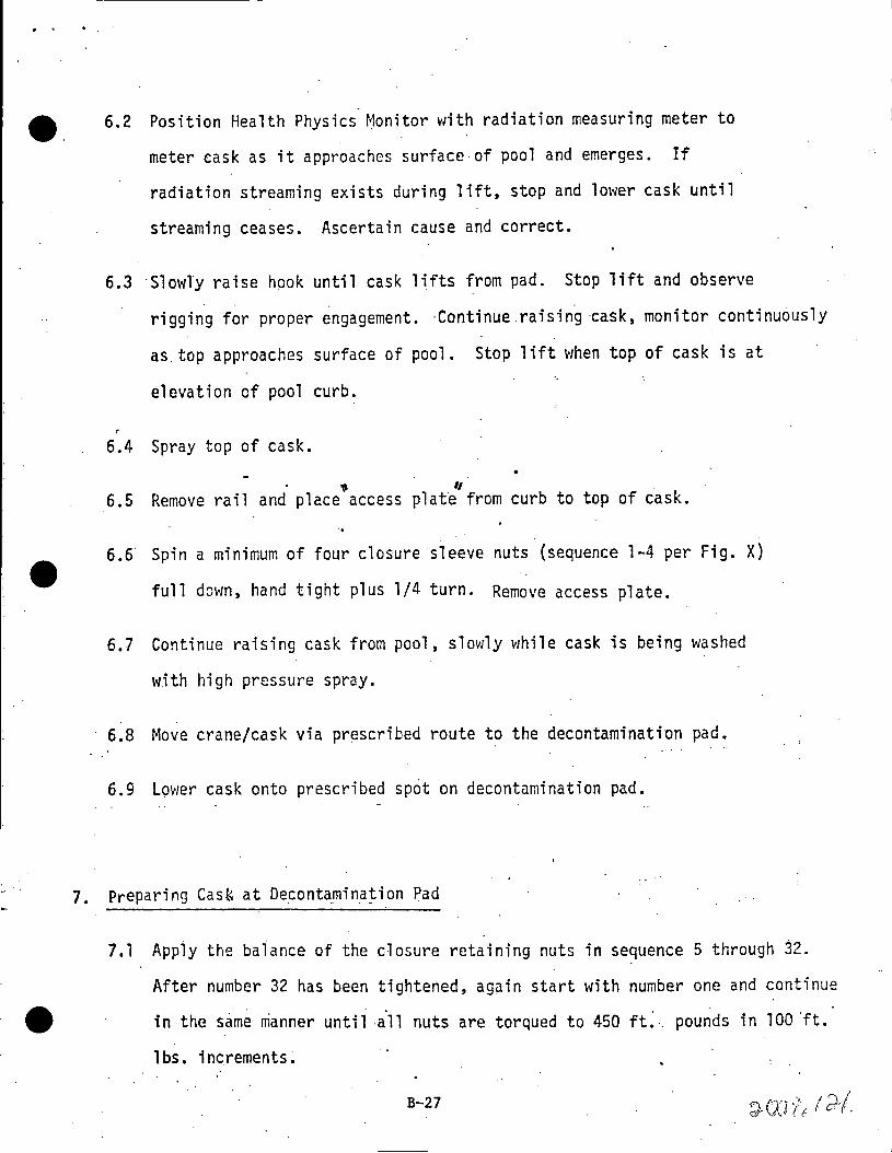
e. 6.2 Position Health Physics Monitor with radiation measuring meter to
meter cask as it approaches surface of pool and emerges. If
radiation streaming exists during lift, stop and lower cask until
streaming ceases. Ascertain cause and correct.
6.3 ·slowly raise hook until cask lifts from pad. Stop lift and observe . .
rigging for proper engagement. ·Continue raising ·cask, monitor continuously
as top approaches surface of pool. Stop lift when top of cask is at
elevation of pool curb.
6.4 Spray top of cask.
" ,, 6.5 Remove rail and place access plat~ from curb to top of c~sk.
6.6· Spin a minimum of four closure sleeve nuts (sequence 1-4 per Fig. X)
full down, hand tight plus 1/4 turn. Remove access plate.
6.7 Continue raising cask from pool, slowly while cask is being washed
with high pressure spray.
6.8 Move crane/cask via prescribed route to the decontamination pad.
6.9 Lower cask onto prescribed spot on decontamination pad.
7. Preparing Cas~ at De_contamin_a~ion Pad
7.1 App1y the baiance of the closure retaining nuts in sequence 5 through ~2.
After number 32 has been tightened, ag~in start with number one and continue . .
in the s~me ~anner until ·all nuts are torqued to 450 ft~ . pounds in 100 'ft.
lbs. increments:
B-27
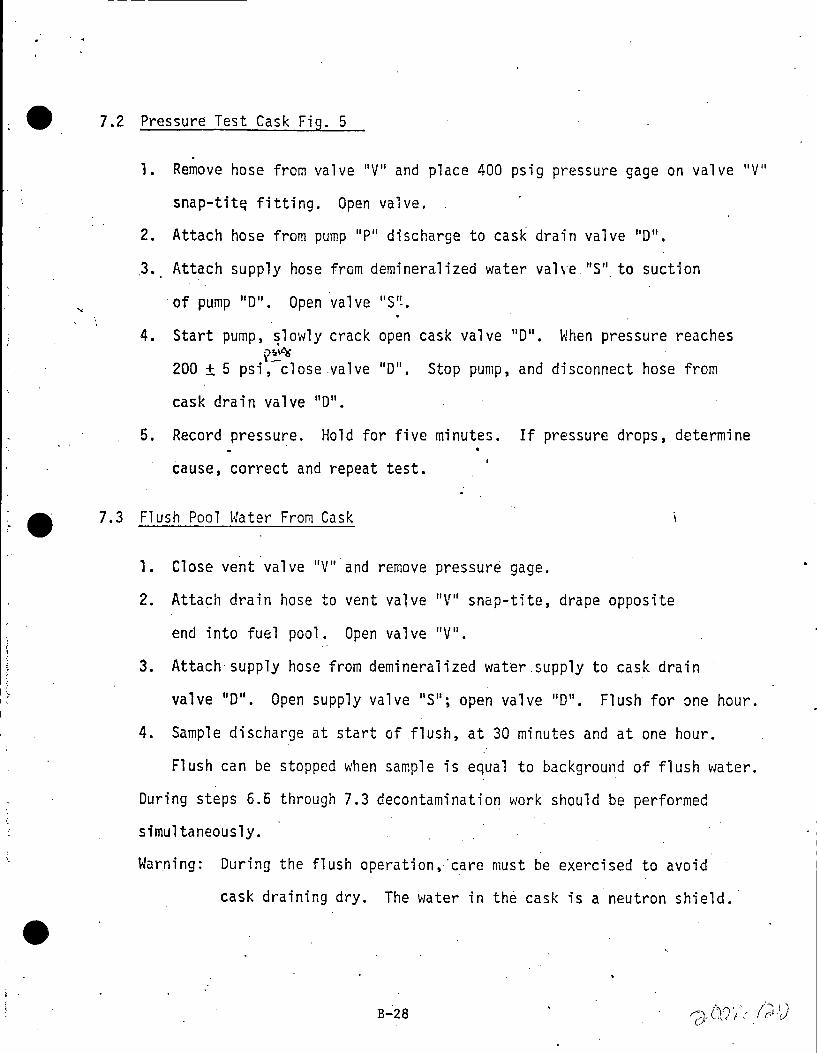
I
~ 7.2 Pressure Test Cask Fig. 5
. 1. Remove hose from valve 11 V11 and place 400 psig pressure gage on valve 11 V11
snap-tit~ fitting. Open valve.
2. Attach hose from pump 11 P11 discharge to casl< drain valve 11 011•
3. Attach supply hose from demineralized water val\·e 11 S''. to suction
·of pump 11 0". Open valve 11 S'~.
4. Start pump, ~lowly crack open cask valve 11 0". When pressure reaches y~'K
200 ± 5 psi, close valve 11 011• Stop pump, and disconnect hose from
cask drain valve 11 011•
5. Record pressure. Hold for five minutes. If pressure drops, determine
cause, correct and repeat test.
7.3 Flush Pool Water From Cask
1. Close vent valve 11 V"and remove pressure gage.
2. Attach drain hose to vent valve 11 V11 snap-tite, drape opposite
end into fuel pool. Open valve "V 11•
3. Attach supply hose from demineralized water supply to cask drain
valve "D". Open supply valve "S"; open valve 11 011• Flush for ~ne hour.
4. Sample discharge at start of flush, at 30 minutes and at one hour.
Flush can be stopped when sample is equal to background of flush water.
During steps 6.6 through 7.3 decontamination work should be performed
simultaneously.
Warning: During the flush operation, ·care must be exercised to avoid
cask draining dry. The water in th~ cask is a neutron shield.
B-28
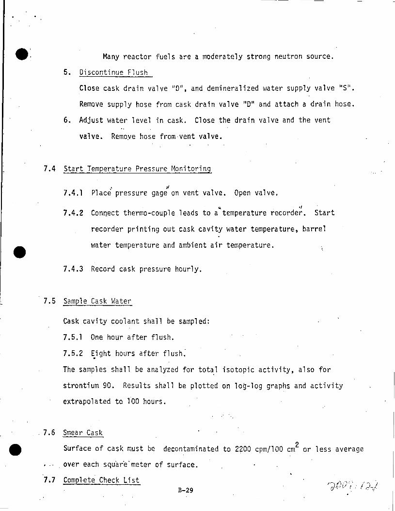
~: Many reactor fuels are a moderately strong neutron source.
5. Discontinue Flush
Close cask drain valve 11 011, and demineralized v1ater supply valve 11 S11
•
Remove supply hose from cask drain valve 11 011 and attach a drain hose.
6. Adjust water level in cask. Close the drain valve and the vent
valve. Remoye hose from vent valve.
7.4 Start Temperature Pressure Monitoring
' ,, 7.4.1 Place pressure gage on vent valve. Open valve.
~ d
7.4.2 Connect thermo-couple leads to a temperature recorder. Start
recorder printing out cask cavity water temperature, barrel
water temperature and ambient air temperature.
7.4.3 Record cask pressure hourly.
7.5 Sample Cask Water
Cask cavity coolant shall be sampled:
7.5.1 One hour after flush.
7.5.2 ~ight hours after flush:
The samples shall be analyzed for total isotopic activity, also for
strontium 90. Results shall be plotted on log-log graphs and activity
extrapolated to lbO hours .
. 7 .6 Smear Cask
Surface of cask must be decontaminated to 2200 cpm/100 cm2 or less average
. over each squar·e ·meter of surface.
7~7 Compl-ete Check List B-29

9 7.8 Remove Temperature Monituring Connections
8. Return Cask to Skid Frame
The cask will normally have crane hook with yoke attached to the cask. If,
however, the crane hook.has been released for other service, then the crane.
' hook· must be affixed to the cask yak~ and the yoke re-engaged to the cask
trunnions per item 3.5 of this procedure.
8.1 Remove section of railing at the fuel floor equipme~t hatch to
allow oask to pass. Provide necessary safeguards in lieu of railing
to prevent-personnel falls into the equipment hatch. Replace railing
as. soon as cask has passed through rail opening.
e 8.2 Raise crane hook until bottom of cask can cleor all obstacles on
prescribed route to equipment hatch.
8.3 Move crane laterally to center cask over equipment hatch.
8.4 Lower cask to skid spotted on car/trailer under the hatchway.
8.5 When bottom of c~sk is approximately 6" from the skid socket, stop I·
down travel and adjust lateral travel to center cask bottom over trunnion
socket. ·
8.6 Continue down travel of crane hook until cask is seated in socket and
starts rotation into horizontal position.
8.7 As cask rotates the crane hook must be moved laterally to keep the load
line vertical . • A lateral travel of 13' 3" is necessary; .if this is not
available, the skid must be repositioned by use of capstan (car puller) to
prevent ·1oad cables of crane from striking the combining of the equipment hatch.
B-30

e. Continue down travel of crane hook until cask is resting on saddle.
8.8 Disconnect yoke from trunnions and store.
9. Secure Cask to Skid
9.1' Remove trunnions and .store in equipment box provided. Reverse of 3.3.
The trunnions are very heavy and must be handled with appropriate
lifting hoist.
9.2 Insert pins 11 P11 (each side of cask) through lov1er holes in top lifting
rings and skid saddle. Apply keeper "N 11 .and bolts 11 M'1• Lock wire bolts
11M11 together.
-e 10. Secure valve Boxes
10.l Lock wire drain and vent valves closed. Ascertain that snap-tite
co~pling covers have been replaced.
10.2 Replace valve box covers. Torque four cap screws on each cover to 20 ft. lbs.
11. Position Air Ducts
11.1 Grasp the duct support tube and move each duct towards center of car limit.
11.2 Turn lock pins, two on ·each side, off guide beam and press down into
lock slot.
11.3 Replace snap on couplings, one on each side, connecting ducts to the·
fan exhaust.
B-31

.. .
~12. Start Auxiliary Cooling System
....
Operation of the Duetz engines within the reactor building is permissable;
h6wever, there will b~ a slight diesel odor. If extended operation is
necessary before car is moved out, an exhaust system may be desirable.
12~·1 Disengage Clutch .
12.2 Set speed control to 1/2 load position and press starting fuel allowance
button once.
<
12.3 Push in the switch box key, red charging indicator lamp should light up.
12.4 To preheat the engine, pull heat~r plug starter switch up to the first
stop. The normal preheating time is 30 - 60 seconds; however, during
this operation, check to see that the heater plug indicator slow1y t~k~s
a gl O\'I.
Note: If engine is \'/arm, preheat is not necessary.
12.5 Pull the starting switch out fully. As soon as engine begins to fire,
release starter switch. Do not run starter motor longer than five
seconds. Do not engage starting motor while crank shaft is still rotating
from previous start.
12.6 Cut the speed back as soon as engine is running normally. The charging
indicator light and the· heater plug will have gone out.
12.7 Observe that oil indicator gage pointer is in the green field; if it drops
back to the red, the engine must be stopped.
B-32

;
e· 12.8 Engage clutch and increase speed of fan to 2000 RPM.
12.9 Observe general operation, such as drive belts, fan bearing vibration,
etc. Report any abnormality to GE at MFRP.
Repeat steps 1 through 9 on unit two.
13. Close and Secure Hoods
13.l Grasp the operating levers of the large hood, Fig~. I , (one on each
side) ~nd push toward bottom of cask. Each lever will rotate approximately
30° to lift the hood onto rollers.· Continued push on levers will cause
hood to roll to the full -extended position. Release levers to lower
hood off rollers.
13.2 In like manner, move the center hood to its original closed posi~ion.
13.3 Turn the six locking pin handles and press down into lock position.
13.4 Insert retaining pins in the front of the large hood.
13.5 . Apply pad locks to each of six locking pins of item 3 above.
14. Move Cask Car Into Air Lock
14.1 Place capstan load cable through reversing block and attach hook to frame of car. 1
14.2 Remove car chocks from wheels.
14.3 Place one set of car chocks on track inside of outer air lock door
as a safety stop to prevent car from striking _air lock door.
14.4 R~l~as~ car brakes. B-33
• ~I Iii I
e. 14.5 Move car into air lock.
14.6 Set brake
14.7 Disconnect .
caps ton load cable and rewind.
14.8 Close inner air lock door.
14.9 Complete check list, bill of lading and dispa.tch car.
. ..
B-34

'
• . ~
t . '
.·-·//.. j
~·· ; I "C ...__.·
"'· .. ·
~· i:C,'/I? Q..10 f _.,;_
-·---- -- .. ··--···---------------- ----- -· -----··· ·-· .... - ... -- ·-- ···-·- ·- ..
~r _.-·· . .,-:
. \
/
\ " 'f Q.
O{ \ \
' \ \ ··"'·
-~ \ \
f/" ...
·-· v-t---. e
.. : ·······---~·
i
·-:!:'\ ! l,y-f
' i
rt--/ '2>l· / .... . .......
/ I· .
.. . _, ) . > •
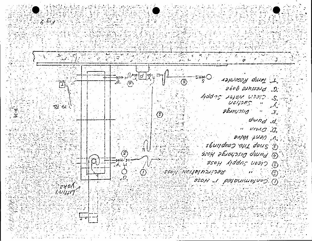
"t.
. :~:: l • ..... ::~ .: ~· .. ~· . ·' ,.
~ .,. . .• :-. ~, · ... -.; ..
r .17 ,"•,··- .. :.
. f .... , ..
~' . .. . ., .. •· ...
. . ~·. ...
:..,I·
' .
. '
,. . ,,
~ . : . ·;. ..· ........
.... . '
t ·.• . .,..~ . . ..
.:..··.- .. · .. .. •• i"' ... .,. "":"
,· -. ~ .-, .. ; .· . ,.
; ...... ... • .... 1',, •
.·. _ ....

S E C T I 0 N c
Technical Description
IF 300 Irradiated
Fuel Shipping Cask
July 1972
NUCLEAR ENERGY DIVISION •GENERAL ELECTRIC COMPANY SAN JOSE, CALIFORNIA 95114
GENERAL. ELECTRIC
;A?:',,··· I " I r;J~/t · .. ~
' ::r\J / t ..

TABLE OF CONTENTS
e. Page
INTRODUCTION ....... , ................................................................................................................................... . Irradiated Fuel Shipping Requirements ................................................................................................... . Alternate Approaches ................................................................................................................................ . Features of the IF 300 Cask ................................................................................................................. .. Licensing and Fabrication Status ............... ........ ........................ .................................... .......................... 4
EQUIPMENT DESCRIPTION ....................................................................................................................... 4 Design Summary ........................................................................................................................................ 4 Cask ........................................................................................................ · ................................................... _ 6
1. Cask Body·············································································:··························································· 6 2. Cask Heads ................ , .......... , ........................................................................................................... 8 3. Closure ............................................................................................................................................... 10 4. Fuel Baskets ...................................................................................................................................... 10
Skid and Supports ..................................................................................................................................... 10 1. Equipment Skid ................................................................................................................................. 10 2. Cask Supports ................................................................................................................................... 14
Cooling System ............. : ..................................... ~: ........ : .............. : ... : ... : ..... :.:: ...................... · ...................... l4 Enclosure .................................................................................................................................................... 16 Cask Lifting Yoke ...................................................................................................................................... 16 Alarm System ................................................................ , ............................................................................ 16
SAFETY ANALYSIS AND LICENSING REQUIREMENTS ...................................................................... 17 Licensing Procedures ............ , .................................................................................................................... 17 Design Conditions ...................................................................................................................................... 17
1. Thirty-Foot Free Fall ........ , ......................... , ...................................................................................... 18 2. Forty-Inch Puncture Test ................................................................................................................... 20 3. Thirty-Minut~ Fire Test. ..................................................................................................................... 20
FUTURE DEVELOPMENT ........................................................................................................................... 21
iii/iv
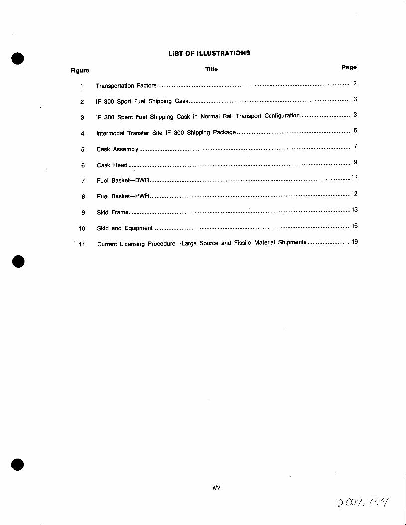
LIST OF ILLUSTRATIONS
Figure Title Page
Transportation Factors .................................................................................................................... 2
2 IF 300 Sport Fuel Shipping Cask ................................................................................................. 3
3 IF 300 Spent Fuel Shipping Cask in Normal Rail Transport Configuration ................ , ............. 3
4 lntermodal Transfer Site IF 300 Shipping Package ........................................ , ........................... 5
5 Cask Assembly............................................................................................................................... 7
6 Cask Head .. .. .. . . .. .. .. .. . .. . . . . . . . .. . . . . .. .. .. .. . .. .. ... .. . .. . ... .. . . .. . .. . . . . . . .. . .. . . .. .. .... .. .. .. . ... .... . ... .. . . . .. .. . . . ... . .. . . .. .. .. .. . 9
7 Fuel Basket-BWR ......................................................................................................................... 11
8 Fuel Basket-PWR ......................................................................................................................... 12
9 Skid Frame ......................................................................... ~ ........................ : ................................... 13
10 Skid and Equipment ....................................................................................................................... 15
11 Current Licensing Procedure-Large Source and Fissile Material Shipments .......................... 19
v/vi

e. INTRODUCTION
IRRADIATED FUEL SHIPPING REQUIREMENTS
The requirements of irradiated fuel transportation pose a significant challenge for the cask designer. Functional requirements for shielding, cooling, ease of handling and contamination control are particularly challenging in view of safety criteria such as demonstration of ability to withstand extreme accident conditions without loss of essential functions.
In addition, the continued trend toward higher specific powers, discharge exposures and station capacities requires casks that are larger, heavier and more complex than any that have been used to date. For example, fuel discharged at the higher exposures will contain sufficiently high concentrations of transuranium isotopes to yield a significant neutron source in addition to the gamma sources. Thus, irradiated fuel shipping casks must contain neutron shielding or ship only fuel which is discharged short of projected goal exposure. The more complex shielding has to be capable of withstanding the same severe accident stresses as before. These significant new requirements impose a need for a totally new generation of casks.
ALTERNATE APPROACHES
A number of studies have been conducted to determine how modern light water reactor spent fuel can be shipped most economically. Alternative cask design concepts fall into three principal categories~
1. Small single element casks suitable for legal weight truck shipments,
2. Casks of a slightly larger size and capacity intended for overweight truck shipments, and
3. Large capacity rail casks.
A special case of significance is the intermodal cask, principally intended as a rail cask but suitable for shipment over short distances by overweight truck. Figure 1 illustrates the weight and payload limitations applicable to each of these cask categories.
General Electric's studies have shown that the cost of irradiated fuel shipment is strongly influenced by cask capacity. For example, unit shipping costs using single element truck casks would be roughly twice those achievable with large rail casks. This cost differential is attributable to the lower payload-to-weight ratio and increased handling requirements of a single element cask. Higher capacity overweight truck shipment represents some unit cost improvement over single element casks but the required reliance on special overweight permits and the restrictions on time of travel and routing, imposed on such shipments, are substantial negative factors. In addition to the direct financial cost and the cost of man-hours required, men will be working in the radiation field associated with the shipping casks. With "as low as practicable" radiation exposure limits applied to workmen handling the cask, the man-hour requirement to ship a batch of discharge fuel becomes increasingly important. Moreover, the impact of spent fuel transportation upon the environment and the public is directly relatable to the number of required shipments.
These considerations-shipping costs, handling requirements, radiation exposure limitations and environmental and public impact-have led us to the conclusion that rail casks are by far the preferred alternative. This choice is complicated, ·however, by the fact that many reactor si.tes do not have direct rail access, and/or cannot handle maximum size rail casks because of equipment limitations. For this reason, General Electric has selected the intermodal concept as its reference cask design. The IF 300 is such an intermodal cask.
FEATURES OF THE IF 300 CASK (FIGURES 2 AND 3)
General Electric's IF 300 is the first of the modern generation of irradiated fuel shipping casks. The capacity is 18 BWR fuel bundles or 7 PWR fuel bundles which have been irradiated to design exposures. Interchangeable heads and internals are utilized to accommodate the different lengths and cross sections
-1-

100 50
w 80 40 c C!l w a: 0.. <( 0.. J: J: u Cl) Cl) c c LARGEST SIZE SHIPPABLE BY LEGAL WEIGHT TRUCK <( ::::> 0 ~ .J
>-0 ~ .,. a: u.. w
60 30 0
0.. z Cl) I- MAXIMUM OVERWEIGHT POSSIBLE FOR TRUCK SHIPMENT
0 z I-w a: ~ w a. 0..
J: Cl)
Cl) z LL 0 0 I-
a: ::t w w. I-1%1 Cl)
::t >-:::> 40 20 Cl)
z .J <( I-0
~ INTERMODAL SHIPMENT
I-
UPPER LIMIT
20 MAXIMUM SIZE RAIL CASK_/i 10
0 .......... __ ......... ____ ............... __ --i. ..... --~-i.------------~------------._. .... 0 o.o 1.0 2.0 3.0 4.0 5.0 6.0 7.0 8.0
CASK CAPACITY (TeU)
22 38 78 97 CASK WEIGHT (TONS)
Figure 1. Transportation Factors
-2-

VALVE BOX
CLOSURE HEAD
VALVE BOX
REMOVABLE FUEL BASKET
NEUTRON SHIELDING
IMPACT FINS
Figure 2. IF 300 Spent Fuel Shipping Cask
MOVEABLE COOLING DUCT
TIPPlp,jG CAAOlE\
REDUNDANT ENGINE/BLOWER COOLING SYSTEM
'""'lOO TON CAPACITY FLAT CAR
CORRUGATED STAINLESS STEEL OUTER JACKET
"IXED COOLING DUCT
Figure 3. IF 300 Spent Fuel Shipping Cask in Normal Rail Transport Configuration
-3-
.··./

of the BWR and PWR fuel bundles. An external forced air cooling system is employed to remove the design basis heat load of 262,000 Btu/hr. Depleted uranium, stainless steel and water provide both gamma and neutron shielding. Capacity, weight and dimensional parameters are as follows:
BWR PWR
Capacity Assemblies ............................................................................................................... . 18 7
Approximate loaded weight Cask only, lb ........................................................................................................... . 140,000 136,000
Skid, enclosure and cooling system, lb ................................................................ . 35,000 35,000
Total System, lb ...................................................................................................... . 175,000 171,000
Cavity Length, in ................................................................................................................ .. 180 169
Diameter, in ............................................................................................................. . 37.5 37.5
Cask Body Length, in ................................................................................................................. . 208 198
Nominal Diameter, in .............................................................................................. . 64 64
Skid Length, ft .................................................................................................................. . 37.5 37.5
Width, ft ................................................................................................................... . 8 8
An intermodal cask, the IF 300, can be transported by overweight truck (for short distances) or by rail. For ease of overweight truck transportation, the IF 300 cask skid is designed to be directly connected to wheel assemblies with hydraulic goosenecks such as those used by most hauling firms specializing in heavy loads. Transfer of the cask from truck to rail car can be readily accomplished by use of an end loading ramp at the rail siding. This transfer is illustrated by Figure 4.
LICENSING ~ND FABRICATION STATUS
Licensing of the IF 300 cask by the USAEC is expected to be completed in 1972. General Electric's Design and Analysis Report for the IF 300 was submitted to the AEC in January 1971, over twelve months earlier than that of any other modern design shipping cask. This represents a substantial lead in the lengthy
AEC licensing process.
Fabrication on long lead-time components of the first two IF 300 casks has begun. Delivery of the
first cask is expected during the second quarter, 1973.
EQUIPMENT DESCRIPTION
DESIGN SUMMARY
The General Electric IF 300 spent fuel shipping cask is designed to ship eighteen (18) BWR (7 X 7) or (8 X 8) elements or seven (7) PWR (14 X 14) or (15 X 15) fuel elements irradiated to design exposures. Failed fuel can also be accommodated.
The various loads are individually accommodated through the use of removable fuel baskets and two different length closure heads.
The cask weight when loaded is between 135,000 and 140,000 pounds depending on the particular type of fuel being shipped. The skid and cooling system weigh approximately 35,000 pounds.
-4-
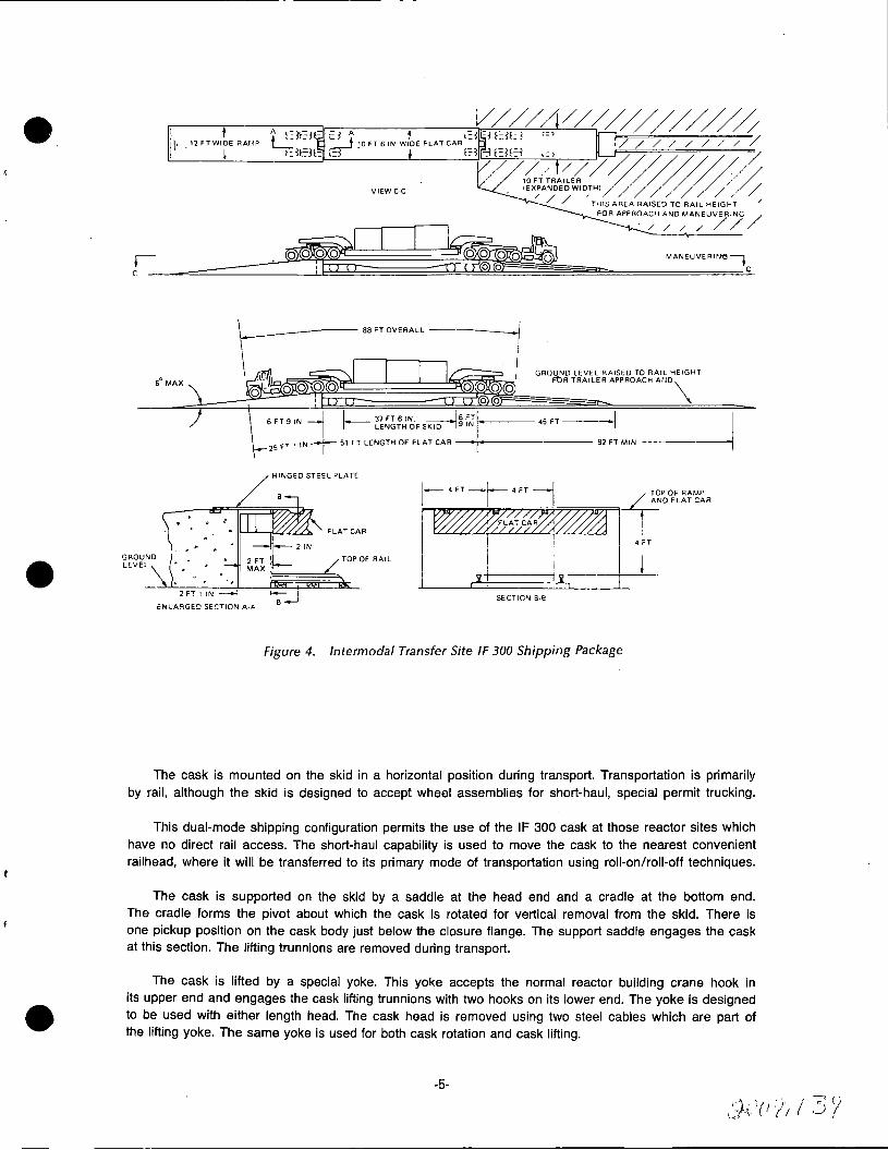
6° MAX
2FT11r..i--l
i:~LARGED SECTION .O..·A
:
GROUND LEVEL RAISED TO RAIL HEIGHT FtlR TRAILER APPROACH AIJO\
6 FT 9 IN -j r-- ~~~J;;~'!;F S~~ i,Jr-:~--- 45 FT I I ' I 25
fT 1 IN~ 51 FT LENGTH OF FLAT CAR --• r-~---·---- 82' FT MIN
HINGED STEEL PLATE
- ; B ..,_J
FLAT CAR
/TOP OF RAIL
I.,.__ 4 FT--~ 4 FT ~ TOP OF RAMP
I I ~OFLATCAR
,....,,..,
1
~~FL~~~~'. ~I .~T ! '
SECTIO'< B·e
Figure 4. lntermodal Transfer Site IF 300 Shipping Package
The cask is mounted on the skid in a horizontal position during transport. Transportation is primarily by rail, although the skid is designed to accept wheel assemblies for short-haul, special permit trucking.
This dual-mode shipping configuration permits the use of the IF 300 cask at those reactor sites which have no direct rail access. The short-haul capability is used to move the cask to the nearest convenient railhead, where it will be transferred to its primary mode of transportation using roll-on/roll-off techniques.
The cask is supported on the skid by a saddle at the head end and a cradle at the bottom end. The cradle forms the pivot about which the cask is rotated for vertical removal from the skid. There is one pickup position on the cask body just below the closure flange. The support saddle engages the cask at this section. The lifting trunnions are removed during transport.
The cask is lifted by a special yoke. This yoke accepts the normal reactor building crane hook in its upper end and engages the cask lifting trunnions with two hooks on its lower end. The yoke is designed to be used with either length head. The cask head is removed using two steel cables which are part of the lifting yoke. The same yoke is used for both cask rotation and cask lifting.
-5-

All external and internal surfaces of the cask are stainless steel. The inner and outer shells are Type 317 stainless steel, and the flanges and fins are AISI 300 stainless steel Type 304. The fuel baskets also are made of stainless steel. Both gamma and fast neutron shielding are provided in the IF 300 cask. Shielding is provided by the presence of water in the cask cavity, depleted uranium metal within the cask shell, and an exterior water-filled enclosure. The exterior shielding water enclosure is fabricated from thin-walled stainless steel, and is corrugated to maximize the heat transfer area. The corrugations also significantly increase the strength of the outer jacket and its resistance to damage. This cylindrical containment is attached to the cask body and masks the active fuel zone.
The closure head is sealed with a metallic gasket. The maximum normal operating pressure for the cask cavity is 200 psig. However, the design working pressure is 400 psig at a material temperature of 815°F. Overpressure protection is provided by a pressure relief valve. Discharge pressure for the valve is 350 psig. The valve is set for a maximum steam or gas blowdown of five percent and a liquid blowdown of ten percent. The cask cavity is equipped with two nuclear service valves, one in each of two valve boxes for filling, draining, venting and sampling. These valves have quick disconnect fittings for ease in servicing. Both valve handles are secured during transit to prevent tampering. A pressure gage with quick disconnect fittings is provided with the cask tool kit. The shielding water containment is protected from overpressure by a 200 psig relief valve. It is also serviced by fill and drain valves located in two valve boxes.
A thermocouple well is attached to the outside of the inner shell at a point expected to experience the highest temperature. The thermocouple well emerges from the cask bottom and accepts a replaceable thermocouple.
The fuel assemblies are contained within a removable, slotted, stainless steel basket; one designed to accommodate BWR assemblies and one for the PWR assemblies. Criticality control is achieved by using B.C-filled, stainless steel tubes welded to the basket. Fuel elements are restrained axially by spacers mounted on the inside of the closure head. The basket is centered within the cask cavity by disc spacers. Nine such spacers are mounted along the fuel basket length. Fuel elements are inserted and removed from the basket using standard grapples. The basket is removed only when the cask is to be used for the shipment of another fuel type.
The outer surface of the cask body is finned for impact protection. These fins are stainless steel and are circumferential to the cask diameter. The cask ends and valve boxes are also finned for impact protection. All fins are welded to the cask surface. The external water jacket is constructed of thin-walled material and does not contribute to the impact protection of the cask.
CASK
1. Cask Body (Figure 5)
The IF 300 cask inner cavity is a Type 317 stainless steel cylinder, 37-1/2 inches inside diameter with 1 /2-inch thick walls. The bottom end of the cavity is sealed with a 1-1 /2-inch thick Type 304 stainless steel plate. The upper end is welded to the closure flange. The inner cavity will be fabricated using ASME Section Ill for guidance.
Surrounding the inner cavity is the depleted uranium metal shielding material. This heavy metal assembly consists of eight annular castings each with a 38-1 /2-inch i.d. and a 4-inch thick wall. Each segment is approximately 20 inches long. The sections are interlocked, end-to-end, using a stepped joint. The overlapping joint design holds the stack together and prevents radiation streaming. This assembly is shrink-fitted to the inner cavity to ensure good thermal contact for heat transfer purposes. The bottom end shield is a 3-3/4-inch thick uranium metal casting.
To prevent the formation of a low melting point alloy of steel and uranium, a 5-mil thick copper diffusion barrier is provided at every uranium-steel interface. The barrier is plated or flame-sprayed on the larger pieces such as the inner and outer shells. Copper foil is used in some of the smaller areas. In welded areas, a copper-plated backup strip is used.
-6-

1s£""'' .... ao ---,_
o"
r
FfTAIL - VA~V4- 60• ASS0
Y (uACAl/..V/Nf S~A4.,. 11t·111I·
tr
f'j'I CA,.'i!.>< A.<;..':.l!'..MBL Y" \!,J ,CAL• 1)1, • 11•
'Ut' ~r I ~-· "
,,,,.JO_,. .. /1111~-11
• HAO•I
s "117-7 .. IJlfT·I~
7 /tllll.,..J
• 11110-a
• ...,,.a 10 ,.,,7•G;
" HJ?-/ ,, ,,,, .. ,
i!"AT•AIA'- .-;: -.o. s I IULlf'tOI
• .. ·-· I l>..11iM'l'I
I ......... I U1. 11at A I L,l'tQ'T
~!-or,x"r
WL.l!iOPi .. ---.. , ... "-.1-!llil_I
I
' ....... .. ,., .... ··~· lw•
"'~' .. ,., II/ IML l~I
'"- 1 .... .,,_,
I
' lllll'U)tt
I .. ···-.. ~ .. 11 .......
Figure 5. Cask Assembly
-7-
"j("i·7' t.! ~:'t\ fl
· 11· /y
The outer body shell is also a Type 317 stainless steel cylinder with a 46-1 /2-inch i.d. and a 1-1 /2-inch thick wall. The outer shell is shrink-fitted to the uranium for heat transfer purposes.
The cylindrical portion of the cask is encircled by a thin-walled corrugated, stainless steel water jacket. This jacket extends axially from the upper valve box to a point slightly above the cask bottom, thus masking the active fuel zone. The water contained in this structure functions as a neutron shield. The jacket surface is corrugated for heat transfer purposes. The use of continuous corrugation also provides a surface which is easily decontaminated. The jacket has a pressure rating of 200 psig and is equipped with fill, flush, and relief valves.
Welded to the outer shell o.d. are four 7-inch high and 1-1/4-inch thick circumferential fins. These members serve as lifting rings and impact fins. They are also used to support the water jacket sections. The IF 300 cask is lifted by a set of trunnions located just below the closure head flange. These items are pinned to the upper set of heavy rings. The lifting trunnions are designed to be removed for transit. The upper set of lifting rings also acts as the forward support/axial restraint when the cask is in the horizontal transport position.
The lower end of the cask is equipped with 32 radially mounted impact fins. These items are also Type 304 stainless steel, 1-1/4-inch thick and approximately 8 inches high. They are welded in place and prepared for ease of decontamination.
There are two large valve cupolas on the exterior of the cask body nested between the pairs of impact fins. These fixtures have finned lids which are removed during loading. The head end valve box contains both a nuclear service vent and flush valve and a pressure relief valve. The lower box contains a fill and flush valve only. Stainless steel Schedule 40 pipe connects the upper valves to the cask cavity side wall near the flange. The lower valve is connected to the inner cavity bottom, 180 degrees from the upper valve location. Both the stainless steel vent and flush valves are equipped with quick disconnect fittings.
Temperature monitoring is performed with a thermocouple mounted between the uranium and the inner cavity. This thermocouple is located equidistant from the ends of the cask body at what is expected to be the hottest axial point. The thermocouple is contained within a well which enters the bottom of the cask, thus permitting replacement.
The overall length of the cask body from fins to flange face is 184-3/16 inches. The cask cavity depth from the flange face is 169-1/4 inches. The flange face contains 32 equally spaced studs each of which is 1-3/4 inches in diameter. The studs protrude 6-1/2 inches from the face and are made of 17-4 PH stainless steel.
The flange itself is an ASTM A-182 Type 304 stainless steel machined forging.
2. Cask Heads (Figure 6)
The IF 300 cask can be equipped with either of two optional heads. These heads provide two different cask cavity lengths to match the particular fuel being shipped. With the short head in place, the overall cavity length is 169-1/4 inches. The long head increases the cavity to 180 inches .. All PWR fuel to date will be shipped using the short (PWR) head. The longer BWR fuel will necessitate using the extended (BWR) head.
Shielding in the heads consists of 3 inches of uranium. The outer shell and flange is a single Type 304 stainless steel machined casting. A circular Type 304 stainless steel plate is welded in place to form the head cover. As in the case of the body, each steel-uranium interface is isolated with a 5-mil copper layer.
Each head has 32 radially mounted fins on the end, 16 of which protrude 9-1 /2 inches from the surface and the remaining protruding 6 inches. These fins are designed to provide impact protection to the cask and contents. The fins are Type 304 stainles~ steel and are welded in place.
-8- 10/\0 1r1_;, ;:J <;:;I' v I ' I'-
II II ..

(9(~ q, '0""-11...L e_ ~-~ C'l!!.OR'C. -'!>"<- ,_.C>\.E'i. 'E.C:,U ... l..L -r <;;,'P .... C:.E l:> 1',.<;,.'!!o>o\OWl'1
IS PW'R \.\'Q>.."'1:>
@BwR HEAi>
CD PWR C ...... ';,K 'M'IO:.J>,1) 1'.'=>~Y. ®BIN R. Cl>..~K 1-\£.N:> A..'bo:;Y.
I tGIS• 10.750
~QI\: /:<>;\
BWR ';./'."=>'«.. 'T-\'l::.."'-"t)
:PPt\"4T T~E TOP S\JRFf\CE OF 'Tlh~ 'F1 ... ll.Pl1..L. OF l'TEM "l..4- 'IN•TH \WO CJ:lta.T~ Ot: .... ii:.F\C.O S.~R.\e'!:r. 8CC ~Al~T SP!to'F'E.'T"( '(~'-LOW No. '9~\0
':£1:,\\D"-\ @ ~w 'R. C"-'O.'< \.\'i:.J>..1:>
@R'l'"C:. A.'o..~HO"'lt.:.-'O'NR ~£.J>o..."'t:> (j)_R\~G. \.£.-.,~ G\l..,':>'E.\'::1-'°'W'R \\'C:......_n
Figure 6. Cask Head
-9-

Because of variations in fuel lengths, it is necessary to provide some spacing scheme. There are a total of flve spacer assemblies for the two heads. These· spacers are mounted on circular plates which bolt to the top of the head cavity. Spacing is accomplished with struts and pads which protrude from the circular plate. Each plate is numbered and indexed to ensure proper installation.
3. Closure
The cask body and either head are joined together using the 32 studs in the body flange and an equal number of special sleeve nuts. Short 3-1 /2-inch length nuts are used to secure the PWR head assembly. Because of its greater length, the BWR head must utilize 13-3/4-inch long sleeve nuts. Using the sleeve nut approach makes it possible to change heads without changing the studs. Two guide pins provide alignment and orientation.
Cask sealing is accomplished using a metallic gasket. The head and body flanges interlock to provide shear steps to protect the gasket during impact. The gasket is designed for a minimum 600 psi burst pressure, and a maximum operating temperature of 1500°F.
4. Fuel F.'askets (Figures 7 and 8)
There are two different fuel baskets which will be used in the IF 300 cask, a 7-cell PWR unit and an 18-cell ·BWR unit. The 7-cell basket holds the various PWR assemblies (15 X 15) or (14 X 14). The 18-cell basket holds the standard (7 X 7) and (8 X 8) BWR fuel clusters.
Each basket "cell" is a square, thin-walled stainless steel tube. The walls of each tube are slotted to provide coolant flow to the contained fuel. The cells are held in place by nine circular spacers equally placed along the basket length. These same spacers center the basket in the cask cavity. The basket cells run the full length of the fuel. When the cask is horizontal, the weight of the fuel assemblies is carried by the spacer discs. The cells are not principal load carrying members; they function as guides for ease in fuel loading.
Criticality control in each fuel basket is provided by boron-carbide-filled stainless steel tubes. These tubes are located in the gaps exterior to the basket cells. D9sign and fabrication of these tubes follows GE-BWR practice for control rod blade absorber members.
Both baskets are of welded, stainless steel construction. Each is keyed into the cask to prevent rotation during shipment. Basket removal is accomplished using a special removal yoke which engages two lifting bars at the upper end of the assembly.
SKID AND SUPPORTS
1. Equipment Skid (Figure 9)
The equipment skid is fabricated by a heavy-duty trailer manufacturer. This structure functions as both a utilized pallet for the cask and cooling equipment and a trailer deck for special permit short haul trucking.
The skid frame uses 24-inch fabricated I-beams. Fuel tanks for the cooling system diesels are incorporated into the framing. Deck plate is provided for all accessible areas. The cooling system and cask support members are attached directly 'to the frame. The skid is 37-1/2 feet long, 8 feet wide, and is all steel construction. Both ends of the skid are designed to accept a type of hydraulic gooseneck assemblies used in the heavy hauling industry. When transporting the package by truck, wheeled assemblies will be attached to both ends of the skid. The gooseneck will be used to lift the unit to a minimum road clearance of 12 inches.
During rail shipment, the skid sits directly on the bed of a slightly modified standard 90-ton capacity flat car. The skid bottom and the rail car surface are coated with an anti-skid material. The skid is restrained by a securing system designed to resist the peak loads anticipated under normal railroad conditions for the hydraulically cushioned draft gear.
-10-.. :, : (~ / 'j 1
'"") j .'.I) { .r_, ' \.; ~ t 't. .1 I l .

'TOP END VtE.W
OE.TAIL ·c· TYPICAL.
~----------- 37.375°01"'-
VJIEW •a-a·
IT&M
"°· DSKlltP'TION
BWR l'UI.\. 9At.KttT &\/R: FUEL BASK.£ T ~V'aA~Sli.M&LY
CIE.LL A9.S'Y. LIFTING LUG C !LL ttMD PLUG Cl.LL aND PLUClo C.ltLL !.ND l'LUG CELL EMO ?LUG CELL END PLUG C.ELL END PLUG CELL !ND PLUG CE.LL 'I.ND PLUG CE.LL REINFORCING Ii!.. C.ll L llEIMFORCIMQ. 12.. POl~ON '200 A.~'!!l'Y.
POISON ROD A.~'!i"Y.
, POl~N R.00 A.'5.~'Y.
POISON ROD A~~ "C'. POl'!ION .R.OD A~$~Y. l.IFTINC9 LUG CELL REINFORC.ING t..
"!I"• f-------------------------------------•~elif
~i·
~---------------------------------------------------------~-t->-1(- ..... ,; a
~~==============~:~==~~==~~::::==~~~==~,~'4===~:~======:::::;~;::::==~'.J:==::::;:;::::======::::~l==~\l='===~~========~~===t,~===~:========~~===t-f====:::=======:::::~===t:~-f====~:=========:~==i"~===~ll::::==================:r::=~~~) ----~
l
1
I
l [
J
I
13R
l
[
l
l
[
r
BL
l
1
I
" I
[ I
....... af ~""~·~·_..;.~-----------------------------------:::-::------------· 1721° !..--~----'---'--------------------------------- •7ea· SECTION"A-"
0 aw ... FUEL 8A5KET
, .... I I [ J
[ I
J ' l I
l
l
I
l
l
Figure 7. Fuel Basket-BWR
· 11 ·

--
VIEW C-C
I&
5~·
1ofl--+-=-A ._J "'ll
St;CTION 0-D
.5ECT/ON A-A RW.R FUEL B!ISK£r R55"t
166£·--
Figure B. Fuel Basket-PWR
-12-

Sll\llC \.O"-"t:>'S' CA..~K =- \40 1occ \..%~. (Fo~ Tie. DowN A"'lf\L'(':J\':> ow\...Y) si>:1::iD\.£. ~ c...i:;co \...,.,'<>. C'R~"t>u;:. ~.q,:;;oo \.~'=>.
CR.~'I:>\.£. PE.DE.SI!>-..\..= '-f:>OO \..'<!.S. E.J>...1:_"'
'"""' : soc'-~"" ..._,._c: ..... E.NG.INE.: C..<;;Q \...'CO:, E.J>...I:_"'-
A .. ~~~~~~~L& (.lt.PPR;.:H,,Loc.A.TIOW)
c
I I I
___ J l,~'l.f!.K·I~·
----·· ------L--+-~-1
( ------- ------ ____ ,,_j
-L I
I ! .J
: ! J ~
_) ~1 . I
'• I ' J.._----..,.-.1---'-+'+'L___c;...----"+'-'--------"+J__---Ul_-"----l:fli.-----'+'--~--"1'1----:----''+-'----~+'-----.--+-~-~~~___j __ L
.J-~"c:'l..OOllt -..;) ~~-.. ~-.'TOTAL C':'!!'~~-=--1'.::..&5•"\';..~~-l:ll-~~-·-·-----4St>"
f---_<;~:~~"·=·=~F~·'-f+---------.. _ ... _-~-:--===-- ---~-1,-.. -.. -.-.. -_·-.-----------------,-7~;~.=:~~=:=~=:~~~~:~:-=(<>.~:=~-.. -)----ll------ -_ J_ t--- ,..,5;~"-!!'i ________________ ,_ ____ ~s•,_" tee .1 i 1---------~~ I
\
'\ 1 · \ ' 'I 1
l-_-.;: ------ --:.-=l~"
I +-·-___.__1 ____________,._~-~· ... &~ --~--I I
/ /
/
I ,'
/1 /
.. _______ ., .. ~--- ff41,-=·- -~-~i-+-~ -~ -p=\-, _._, i1 }tE" ~ 11 \
/ : I -2~-~~"":1P r,-··r~~·-~ :=i r-~:-T~~--"l r--~g~-----1 1
1
r_-_ -;:;,-;;-,_.-;.-1 L.11-- --- -··---~-- - -----~--r- -- r--------·, . ~
L:. L ________ L_J. -~: ___ -~~---J L _________ ..J_' ----+-
\ J "'--. ~-TA."'l""' l..Oc.A."'("10N l\c=.A!=> .... C.liY
"{)q?e:NOE:N"T o~ !:>K\O ·,.'Oil ........ &. CON!iT~UC.T\OlJ. "fOT .... L C.Jri.?A.C.IT""( IU!QUl~E:p • SW4 &A.L
CD SK.ID FR/>o..ME
'~~ t:.
__________ J
l ________ I
Figure 9. Skid Frame
-13-
9. 2. Cask Supports (Figure 10)
The horizontally transported cask is supported in two locations, just below the closure flange by a saddle and at the cask base by a pivot cradle.
The support saddle for the head end is welded directly to the skid frame. This Li-shaped structure engages the cask at its upper lifting rings. Hardened pins are inserted through the saddle ears and through the lifting rings. These pins restrain the head end of the cask in the vertical and lateral directions. The saddle-to-rings engagement provides axial restraint for the total cask weight. During the lowering operation, contact between the saddle and one lifting ring moves the cask forward, slightly away from the bottom of the rear support. This movement provides end clearance for the differential thermal expansion of the cask and skid components. The cask saddle is constructed of ASTM A516 Gr 70 steel.
The pivot cradle supports the base of the cask. This pivot assembly consists of two pedestals and a counterbalanced cradle or "cup." The cradle pivots between the pedestals on two trunnions. These pedestals are welded directly to the skid frame. When the cask is removed, the "cup" remains in a horizontal position with its open end upward. During the replacement operation, the cask base is lowered into the "cup." Two hardened guides provide alignment.
Once the cask is seated in the cradle, the two are rotated downward to the normal transport position. A shoe on the cask base becomes the bearing surface between the cradle and cask when in the transport position. The contact surfaces are coated with Molycote M-8800 to reduce the friction when the cask is moved forward for expansion clearance.
The two cradle-mounted tipping trunnions are held in the pedestals by pillow-blocks. Each block has a lubricated phosphor bronze bushing, to prevent galling. The cradle is counterweighted with lead to hold it in an upright position when the cask is removed. The trunnions are mounted on the cradle slightly off-center so that there is a natural tipping direction toward the cooling system end of the skid when the cask is rotated. Both the cradle and pedestals are constructed from ASTM A516 Gr 70 steel.
COOLING SYSTEM (SEE FIGURE 10)
Cask cooling is accomplished using a unique air jet impingement technique. Air, at a velocity of 47 feet per second, is directed perpendicular to the cask surface from four ducts. These ducts run the length of the cask and are 90 degrees apart, bisecting the four quadrants. The two lower ducts are fixed to the skid. The two upper ducts lock in place during transit, but move outward to facilitate cask removal.
Each duct has a single slot nozzle running its length. Small sheet metal spacers are used to segment this long slot into a number of individual nozzles.
Cooling air is supplied by two Buffalo Forge Company Type BL load limit fans, Size 445. These are counterclockwise rotating upblast units with single inlets. They are equipped with inlet vane dampers, inlet screens and gravity outlet dampers.
The two blowers are driven by a pair of air-cooled Deutz diesel engines, Model. No. F2L-410, complete with SAE No. 5 power take-offs and twin-disc clutches. Power is transmitted to the blowers through two groove, Type C sheaves, using two C-112 V-belts. Electrical power is supplied by two 12-volt heavy duty batteries. Instrumentation includes:
Tachometer with hour recorder Key type starter switch Fuel level gage Generator warning light
-14-

1
~ ,,, .'
·:- -..1
:j ---c?.:::.
I
5!!CTIONfO\
-HC.DOH@
i (Z!!'·~~~c;_~=~-u_:-L 9•.e.-. C,h,,,•g
--.....,_ --~c....:::_-: ..::..__ __ --- _-:-:.:: :.:~·?,_-;;::~----": ,-, ·-. ---.2~;-q-Cu~"r·-(~<>.;_~-,;-:..~ .. .;--. -
SEC:llON .:'§:\
/
I' x-.:~.'
=-/t=§lH L--r-~~-+=i-~~~~~~~~~--' I
! '·
I ,,
==:1~~u·~~.;;;t..c:======,============i -- -·7-- -- -- -~.:. -·_: ~_:.::::... __ .; __ --._ --::-·
__ 5ECTiON· @ -Ll::55 CA!'>K. <\-
-·--..:v
~ N."'t..'S-\ ~b...N l:>RW~ ,ei....c;,,~-''<":.:.·-----l 'i Ni.."'?.\-' [E,.t.;.I:> W~"-'- -/.a....c..c..'-.--=~ ~CQR
, ~ ""''~-\ i £..~~,~~~'?.;::.~---~ M~\-C:>O ~""' ... '-'- ~NCLO"';:,u~'L .a..r.,<::.~"""t:-\.."Y
10 ~"Z.\-C:..\ \...i:o..~~'i:. 'a...~C..L<:::i'b\JR.~ .C..~"";i...."-1\~.
\\ ~\"?.-'?.... c:.. .... ~'f<. 'c:.l.l~ "N.P..\...\....
l"Z.. ""'-'~-\ C~£R;i....\\"'1C::.. ~~'"""°t-.~\~N\ ~~S'ci \'=i tiw\Z..\-\Z.. 'S;.\l:::i'i:: 'li=~i:>...""~ !It,,.<;.::;"\- - ~~
\4 Wt."?.\-\~ ~\"t:>t. 'i="~1:tr...1'J\t:. J1...~SY--'-\-i.. \S l.\\C-\ C:,.'i<.\'t:> ~R,b..Mt_-Dt.C::.'1<.. F\....Slo..N
\~ ~~!j-\~ C:..-.:t..t::o..b'-'t- ~~~\N~~--' 11 M3Z.- \ GPl.S<.E.T "B.:>"'- f'.S S-'
.\~ 1M.4A..-\ C:,~l:::>"bLE _________ _.
!
I
H-·
NOTIO.'O' --i;-- ' -~ 1 ·NQ.'R..'t..G,_"t· .. ~~.O'N"'- \S 'FOP- ·:::-:t~t._ ~~C::.£..~~'-'<"-
:'Z,..~O'-"T ..,,,,_'::::>'-~~~.OR ~~~""Tt...\.=<'~"'·C ~0)(.., ~1E..L\ C::.\,,)~ •• :~,:n_, l="\X~"b "t:-~J'--'~· ~ c~~~'-~ srR\'t...l..:::i. s""'\~? 'a ~~ \..OC."'-"'l;".:~ !\, 'D"'-\1...1...'< . .''D "'-""' ..,-,._,,.._~ 1'>-'=>S£."-'I:>~'(".
!!.~ ..... ~~'...::i...~~ 00 'IW=',b...~\'C.~ 7..-.:.~-;:i.;,.c=::,~t_"-"'2-_,\_\~ c:":::i \<:::> ~K\~, :to"""'- :::"-""~R...,..\Nt.~ 'OY ..,-;>,~'T<_IC::..i:>...,~-=<. '--"'~R; ':.'K\1::. . \l\ .... ,,. 1!.'"-t.>J. 'l::i~-<;,\<;...:,"->:>.
Figure 10. Skid and Equipment
-15-
///'() . ' ;: ~

Each engine/blower unit is independent of the others and capable of producing a minimum flow of 10,000 cubic feet of air per minute. During normal operation both units will be run simultaneously, delivering ""18,000 cfm to the cask surface. Fuel tanks are located in the skid and have a total capacity of 570 gallons. This quantity will permit the continuous running of both units for 10 days. Either one of the units is capable of supplying sufficient air to cool the cask surface.
Both blowers discharge into a common air plenum. The plenum feeds the four axial ducts which cool the cask. If one blower fails, a gravity damper prevents a back-flow of air from the plenum. Screens prevent debris ingestion. Intakes are located within a screened enclosure and are well isolated.
ENCLOSURE (SEE FIGURE 10)
Exclusion from the cask and cooling system is provided by an aluminum frame and expanded metal cage. This enclosure is in three sections. Two sections are over the cask and the third covers the cooling system,. The two cask enclosures move along a rail and telescope over ttie third one, which is semi-permanent, to facilitate cask removal. The enclosure ends are also semi-permanently attached to the skid. The cage extends out to the edge of the 8-foot wide skid. When the movable sections are retracted, the rails form a sill which protects the botto[ll ducting and provides a work platform along the cask. When the sections are in place over the cask, a locking device lifts them off of their tracks and secures their movement. This device is padlocked during transit.
The cooling equipment end wall has a lockable access door for inspection. In addition, there is one small removable panel on each side of the equipment enclosure which permits access to each of the engine/blower instrument consoles. The equipment enclosure and the end walls may be removed by unbolting.
All three sections have solid roofs for sun shading. The enclosure ends are also solid. This entire enclosure makes the nearest accessible shipping package surface approximately 4 feet from the cask centerline.
CASK LIFTING YOKE
The cask lifting yoke is a steel structure which engages a· building crane hook at the top and the IF 300 cask lifting trunnions at the bottom. This yoke is used for all cask handling operations including removal and replacement on the equipment skid, insertion in the fuel pool, and head removal and installation.
The upper engagement with the building crane hook is accomplished using a retractable 6-inch diameter AISI 4340 heat-treated pin. The cask trunnions are engaged by the yoke legs.
The yoke cross-member holds two plow steel (with steel center) cables which are used to remove the cask head.
The entire structure, except for the lifting points, is painted for corrosion protection. All lifting pins and hooks will be nondestructively tested for internal and surface flaws. All components of the lifting yoke have a minimum safety factor of 3 in compliance with Federal requirements.
ALARM SYSTEM
The IF 300 cask is equipped with an audible alarm system. System activation occurs if the cask temperature exceeds a predetermined value. This indicates either the failure of the cooling system or a loss of water from the external water jacket.
Each blower-engine combination is provided with a device which will permit a visual verification of the equipment operation. This visual indicator, combined with the audible alarm, will determine the cause of the over-temperature situation.
Transportation personnel, railroad or highway, will be given adequate training to respond to this alarm. A procedures and notification manual will accompany each shipment.
-16-

e. SAFETY ANALYSIS AND LICENSING REQUIREMENTS
LICENSING PROCEDURES
Radioactive material shipping containers for large source and fissile materials are currently licensed in much the same way as reactors and reprocessing plants. Figure 11 shows the current licensing procedure for such shipments. The cask design is evaluated against the regulatory requirements and spacial conditions of transport as defined in AEC and U.S. Department of Transportation (DOT) regulations. After suitable analysis, a Safety Analysis Report describing the cask design and analysis and a description of the proposed contents are submitted to both the Atomic Energy Commission and the Department of Transportation. The AEC application is for a license to possess the material using the specified equipment and to deliver the material to a carrier for transportation. The DOT application is for a special permit for the containers to permit the shipment of the specified contents in the container. In addition to the technical documentation, the AEC application must include a statement of financial and technical qualifications of the applicant to engage in the proposed activities. Regulation changes designed to consolidate the entire review and approval in the AEC have been proposed but have not been finally adopted. However, such a consolidation will affect only the procedural aspects of license approval.
At present, the DOT requirements in regard to design conditions are the same as those of the AEC and, consequently, the DOT does not make an independent review of large source and fissile material shipments. Rather, the AEC completes its review through independent analysis and a series of meetings with the applicant which finally results in issuance or denial of a license. Upon issuance of the AEC license, a copy is sent to the DOT which it accepts as proof that the package meets its requirements as to structural integrity and protection against criticality.
Upon receipt of the license from the AEC, the DOT then completes its evaluation and issues a DOT special permit, assigning a number to the shipping container. Upon receipt of both the AEC license and the DOT special permit, the material can then be packaged in a container and delivered to a carrier for transport to another iicensee who is authorized by the AEC to receive the contents of the package.
DESIGN CONDITIONS
The regulations specify both normal and accident conditions against which the radioactive material packaging design must be evaluated. These conditions are intended to assure that the package has requisite integrity to meet all conditions which may conceivably be encountered during the course of transportation. The normal shipping conditions require that the package be able to withstand temperatures ranging from -40°F to +130°F and vibrations, shocks and wetting incident to normal transport. In addition, the packages are required to withstand specified accident conditions with the release of minimum radioactiviiy. The accident conditions for which the package must be designed include, in sequence, a 30-foot free fall onto a completely unyielding surface, followed by a 40-inch drop onto a 6-inch diameter pin, followed by 30 minutes in a 1475°F fire followed by 8 hours immersion in 3 feet of water. For comparison, a 60 mph transportation accident imposes far less stress upon critical cask components than does the 30-foot free fall onto an unyielding surface, as discussed in detail in a later section of this document.
The permissible radiation levels and releases under these shipping conditions are shown in Table 1. The levels shown in Table 1 are regulatory limits; actual release will be much less.
It should be noted that there is a wide margin of safety in the container design itself. The container is required to withstand the accident conditions imposed pursuant to 1 O CFR Part 71 with only relatively minor damage to the container and no release of the contents except for a small amount of coolant and a small quantity of noble gases. For example, the IF 300 shipping cask is designed to absorb the total effects of the impact with only minor deformation of the -outer fins that have been provided for impact protection. No credit is taken for deformation of the outer steel shell. Thus, because of the relative strength of the shell as opposed to the impact energy-absorbing fins, there is a wide margin between the damage that would be experienced by the cask in absorbing the energy of the 30-foot free fall and that which would be required to breach the container such that there could be a release of the radioactive contents.
-17-
.: 1.1111 i,,, I_,./;/ ·•·v I .. '

Table 1 CONTAINER DESIGN REQUIREMENTS
External Radiation Levels Surface ................................................................ . 3 feet from surface ............................................ . 6 feet from surface ............................................ .
Permitted Release Noble gases ..... -................................................... . Contaminated coolant. ........................................ .
Other .................................................................... .
Contamination Levels {3 - "{ .................................................................. . 0: .......................................................................... .
Normal Conditions
200 mR/hr
10 mR/hr
None None
None
2200 dpm/100 cm2
220 dpm/100 cm 2
Accident Conditions
1000 mR/hr
1000 Ci 0.01 Cio:, 0.5 Ci MFP,
10 Ci I
None
It is unlikely that the casks will experience conditions as severe as those imposed by the 10 CFR Part 71 requirements and, in any event, conditions far more severe than those would be required to result in a substantial breach of a container. As shown in the analysis below, the proposed tests are representative of conditions at least as severe as those which would be experienced by containers in transport. Further, since the tests are required to be applied to the containers in sequence, the cumulative severity of conditions to which the containers are subjected to all probability far exceeds that to which the containers would ever be subjected as a result of an accident in the course of transportation. It is highly improbable that a container would be subjected to conditions as severe as even one of these conditions, let alone all three, in the sequence provided for in the test.
1. Thirty-Foot Free Fall
The shipping cask is required to withstand a 30-foot free fall onto a completely unyielding surface. This requires that all the energy of the impact be absorbed by deformation of the container. In addition, the container impact must be considered from all possible orientations to assure that the impact protection provided is adequate regardless of the orientation of the fall. Based on previous design experience, it is estimated that a shipping cask will decelerate (stop) upon impact within a distance of 2 to 8 inches. To provide a basis for this comparison it has been assumed that a shipping cask would decelerate completely within 6 inches after impact with the unyielding surface. Table 2 shows a comparison of the various forces which would be generated by the stopping of the shipping cask, an overweight truck, or an automobile traveling at various speeds upon striking an unyielding surface. As indicated in the table, a 45,000-pound shipping cask traveling at 30 mph, which is the terminal velocity following a 30-foot free fall, would create 2,700,000 pounds of force if stopped within a distance of 6 inches. A 130,000-pound cask, which is equivalent to the IF 300, would generate about 7,800,000 pounds of force. A loaded truck, weighing 75,000 pounds and traveling at 60 mph coming in contact with the unyielding surface decelerates within approximately 1 O feet. Under these conditions, the truck would generate a maximum of 900,000 pounds of force, or about 1 /3 of the force that would be generated by the 45,000-pound cask as a result of the 30-foot free fall. Likewise, a 5,000-pound automobile traveling at 80 mph hitting an unyielding surface stops in approximately 5 feet and would generate about 220,000 pounds of force. Thus it is seen that typical objects which the cask might encounter would generate substantially less force than the shipping cask because of the relatively weaker sections of their structures and the greater distance required to decelerate those bodies.
-18-
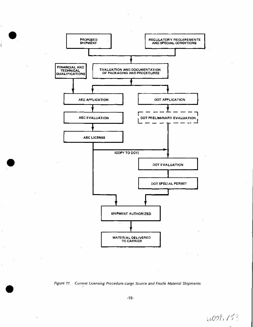
PROPOSED SHIPMENT
REGULATORY REQUIREMENTS AND SPECIAL CONDITIONS
FINANCIAL AND TECHNICAL
QUALIFICATIONS EVALUATION AND DOCUMENTATION
OF PACKAGING AND PROCEDURES
AEC APPLICATION
AEC EVALUATION
AEC LICENSE
(COPY TO DOTI
SHIPMENT AUTHORIZED
MATERIAL DELIVERED TO CARRIER
DOT APPLICATION
DOT EVALUATION
DOT SPECIAL PERMIT
Figure 11. Curr~nt Licensing Procedure-Large Source and Fissile Material Shipments
-19-
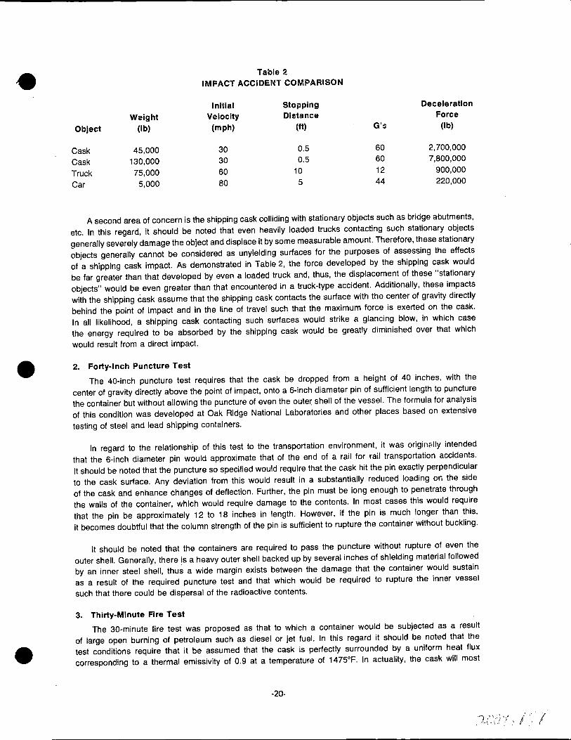
Table 2 IMPACT ACCIDENT COMPARISON
Initial Stopping Deceleratlon
Weight Velocity Distance Force
Object (lb) (mph) (ft) G':; (lb)
Cask 45,000 30 0.5 60 2,700,000
Cask 130,000 30 0.5 60 7,800,000
Truck 75,000 60 10 12 900,000
Car 5,000 80 5 44 220,000
A second area of concern is the shipping cask colliding with stationary objects such as bridge abutments, etc. In this regard, it should be noted that even heavily loaded trucks contacting such stationary objects generally severely damage the object and displace it by some measurable amount. Therefore, these stationary objects generally cannot be considered as unyielding surfaces for the purposes of assessing the effects of a shipping cask impact. As demonstrated in Table 2, the force developed by the shipping cask would be far greater than that developed by even a loaded truck and, thus, the displacement of these "stationary objects" would be even greater than that encountered in a truck-type accident. Additionally, these impacts with the shipping cask assume that the shipping cask contacts the surface with the center of gravity directly behind the point of impact and in the line of travel such that the maximum force is exerted on the cask. In all likelihood, a shipping cask contacting such surfaces would strike a glancing blow, in which case the energy required to be absorbed by the shipping cask would be greatly diminished over that which
would result from a direct impact.
2. Forty-Inch Puncture Test
The 40-inch puncture test requires that the cask be dropped from a height of 40 inches, with the center of gravity directly above the point of impact, onto a 6-inch diameter pin of sufficient length to puncture the container but without allowing the puncture of even the oute~ shell of the vessel. The formula for analysis of this condition was developed at Oak Ridge National Laboratories and other places based on extensive
testing of steel and lead shipping containers.
In regard to the relationsh.ip of this test to the transportation environment, it was originc;.lly intended that the 6-inch diameter pin would approximate that of the end of a rail for rail transportation accidents. It should be noted that the puncture so specified would require that the cask hit the pin exactly perpendicular to the cask surface. Any deviation from this would result in a substantially reduced loading on the side of the cask and enhance changes of deflection. Further, the pin must be long enough to penetrate through the walls of the container, which would require damage to the contents. In most cases this would require that the pin be approximately 12 to 18 inches in length. However, if the pin is much longer than this, it becomes doubtful that the column strength of the pin is sufficient to rupture the container without buckling.
It should be noted that the containers are required to pass the puncture without rupture of even the outer shell. Generally, there is a heavy outer shell backed up by several inches of shielding material followed by an inner steel shell, thus a wide margin exists between the damage that the container would sustain as a result of the required puncture test and that which would be required to rupture the inner vessel
such that there could be dispersal of the radioactive contents.
3. Thirty-Minute Fire Test
The 30-minute fire test was proposed as that to which a container would be subjected as a result of large open burning of petroleum such as diesel or jet fuel. In this regard it should be noted that the test conditions require that it be assumed that the cask is perfectly surrounded by a uniform heat flux corresponding to a thermal emissivity of 0.9 at a temperature of 1475°F. In actuality, the cask will most
-20-
I' ' '(
. ' (
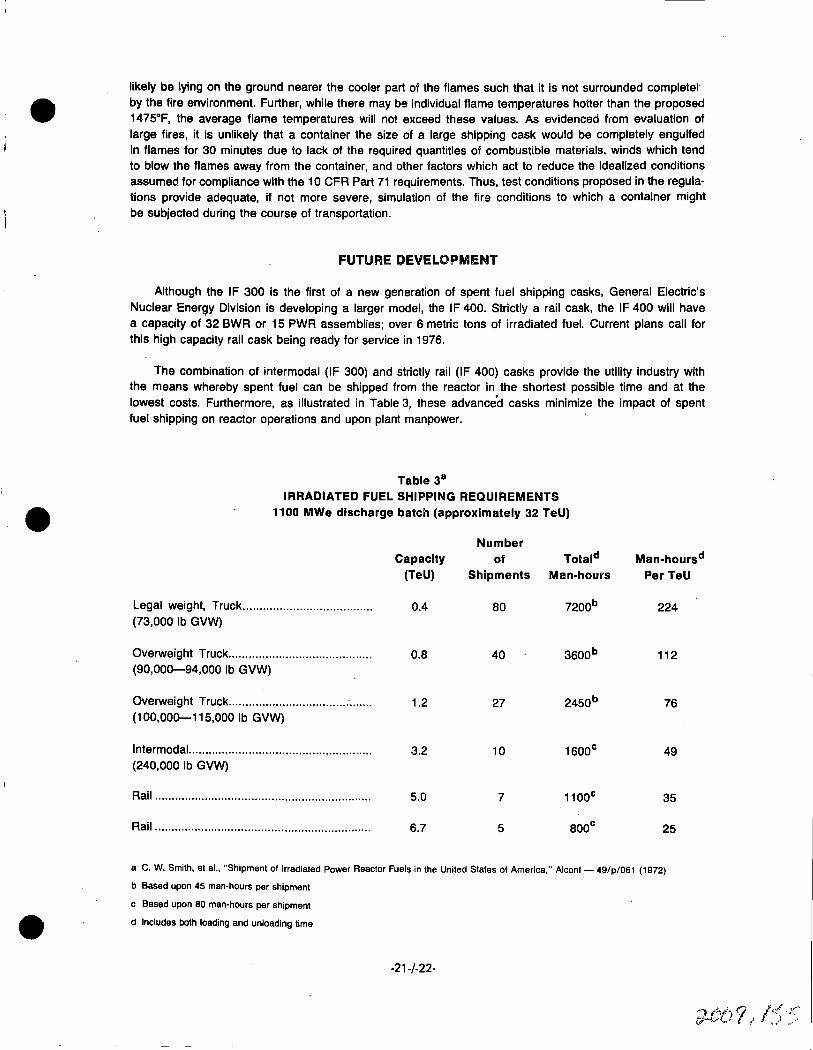
likely be lying on the ground nearer the cooler part of the flames such that it is not surrounded complete!· by the fire environment. Further, while there may be individual flame temperatures hotter than the proposed 1475°F, the average flame temperatures will not exceed these values. As evidenced from evaluation of large fires, it is unlikely that a container the size of a large shipping cask would be completely engulfed in flames for 30 minutes due to lack of the required quantities of combustible materials, winds which tend to blow the flames away from the container, and other factors which act to reduce the idealized conditions assumed for compliance with the 1Q CFR Part 71 requirements. Thus, test conditions proposed in the regulations provide adequate, if not more severe, simulation of the fire conditions to which a container might be subjected during the course of transportation.
FUTURE DEVELOPMENT
Although the IF 300 is the first of a new generation of spent fuel shipping casks, General Electric's Nuclear Energy Division is developing a larger model, the IF 400. Strictly a rail cask, the IF 400 will have a capacity of 32 BWR or 15 PWR assemblies; over 6 metric tons of irradiated fuel. Current plans call for this high capacity rail cask being ready for service in 1976.
The combination of intermodal (IF 300) and strictly rail (IF 400) casks provide the utility industry with the means whereby spent fuel can be shipped from the reactor in the shortest possible time and at the lowest costs. Furthermore, as illustrated in Table 3, these advance'd casks minimize the impact of spent fuel shipping on reactor operations and upon plant manpower.
Table 3 11
IRRADIATED FUEL SHIPPING REQUIREMENTS 1100 MWe discharge batch (approximately 32 TeU)
Legal weight, Truck ..................................... .. (73,000 lb GVW)
Overweight Truck .......................................... . (90,000-94,000 lb GVW)
Overweight Truck ................................... : ...... . (100,000-115,000 lb GVW)
lntermodal. ..................................................... . (240,000 lb GVW)
Rail ................................................................ .
Rail ................................................................ .
Capacity (TeU)
0.4
0.8
1.2
3.2
5.0
6.7
Number of Tota Id
Shipments Man-hours
80 7200b
40 3600b
27 2450b
10 1600c
7 11ooc
5 800c
Man-hoursd PerTeU
224
112
76
49
35
25
a C. W. Smith, et al., "Shipment of Irradiated Power Reactor Fuels in the United States of America," Alcon! - 49/p/061 (1972)
b Based upon 45 man-hours per shipment
c Based upon BO man-hours per shipment
d Includes both loading and unloading time
-21-/-22-

9· '.
S E C T I 0 N D
.e
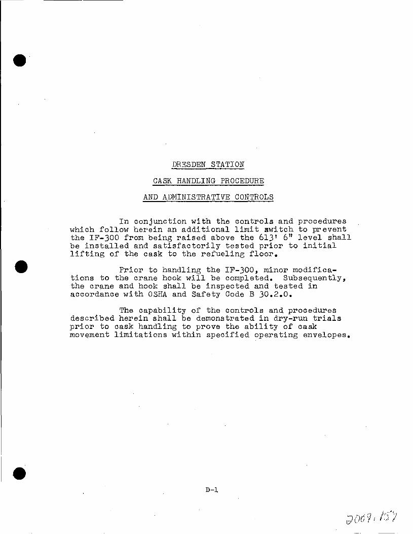
e·
DRESDEN STATION
CASK HANDLING PROCEDURE
AND ADMINISTRATIVE CON'rROLS
In conjunction with the controls and procedures which follow herein an additional limit switch to prevent the IF-JOO from being raised above the 61J' 6" level shall be installed and satisfactorily tested prior to initial lifting of the cask to the refueling floor.
Prior to handling the IF-JOO, minor modifications to the crane hook will be completed. Subsequently, the crane and hook shall be inspected and tested in accordance with OSHA and Safety Code B J0.2.0.
The capability of the controls and procedures described herein shall be demonstrated in dry-run trials prior to cask handling to prove the ability of cask movement limitations within specified operating envelopes.
D-1
DRESDEN.STATION
CASK HANDLING PROCEDURE
MA.Y 1973
This procedure assumes the cask car has been delivered to the site air lock.
1. Inspect car and transport system upon arrival at the reactor site. Health
Physics survey car and cask. If damage is evident, contact. General Electric
Company at the Fuel Recovery Plant as to advisability of continued use of
.equipnent.
1.1 Obtain cask handling check-off list.
1.2 Assure that inner air lock door is closed and locked.
1.3 Unlock and open. outer air lock door.
1.4 Couple Commonwealth F.dison locomotive to cask car an:i position cask car in
air lock.
1.5 Set cask car brake and place wheel chocks fore and aft of car --- uncouple
locomotive and remove from air lock •
. 1.6 Close outer air lock door and lock.
2. · Spot Ca.r Under Eguipnent Hatch
· 2.1 Unlock and open inner air lock door.
2.2 Attach track mobile (Whity Corp.- Type lTM) to position cask car. (See S&L Drawing# B-599 attached hereto.)
2.3 Remove wheel chocks and release car brake.
2.4 Move car slowly through inner air lock door until trunnions or cask are
located under crane hook when hook is at its south limit in the equipment
hatch. 'This will be located ex!'0rimenta.lly durin~ the first time cask is
at the site. Place index marks on the rail or floor for future reference.
2.5 Set brake and place wheel chocks fore and aft of car.
D-2

3. Unloading Cask from Skid Frame
3.1 Open Hoods (Fig. 1)
3.1.l Remove two retaining pins 11 A" on front corner of large hood.
3.1.2 Release six hood lock pins "C", three on each side, by turning
handles "B" 90°M, raising to limit and turning handles into re-
ta.ining notches to hold pins in unlocked position.
3 .1.3 Remove two padlocks "D" securing lock handles (E). Raise the . . 0 -
handles to limit and turn them 90 into retainer to hold them
open.
3 .1.4 Grasp operating levers "G'', one on ea.ch side of center hood, push
handle toward aurlliary equipment end (end B) of skid frame. Each
lever will rotate approximately 30° to lift hood onto rollers.
Continue push on levers until center hood telescopes over auxiliary
equipnent hood. Release levers to lower center hood off rollers.
3.1.5 Move large hood in like manner until it is telescoped over equip
ment hood.
3.1.6 Remove two snap-on air duct couplings "R" on the upper air ducts,
one on each side. (Fig. 2)
3 .1. 7 Raise the four duct lock pins "K", two on each side, until pin
clears top of guide "L", turn pin so it rests on the guide, retained I
in open pos'ition.
3 .1. S Grasp the duct support tube ·11S11 and move the duct outward to limit.
3.2 Remove Valve Box Covers
The cask cavity valve boxes are located between the upper and lower energy
absorbing rings, on top of the cask when cask is in the horizontal position
on the skid frame.
1. Remove four cap screws securing e~ch of urper and lower valve box covers.
D-3

·'"--· ·; . .,..
~ ..
fi~Erz .-------:.----~~------------' -<a
·I
II !:::::=:====:::::' -· ___ _.; l----_;
1;k :! l1 ) , ____ x_:i(~. _}.-1 _ ___,..'·..._. _· ~..d.......,:~t~_...~_'_· , ___ ;.!..' ' A
rrn------_:.-·· . ._,._. < .. -= 11: • -<c,,-,p ~:~, ,-_- /~,-,, . - ~~.~~~~~·~'~.~-~~~-
I
- I I I I -
I ---r ... \ f ?.__,..__: 1-< ) -
''---- I 1§! _ r ~ t ··:_,~
ry--- •·I II II II II 1, 11
I
I i
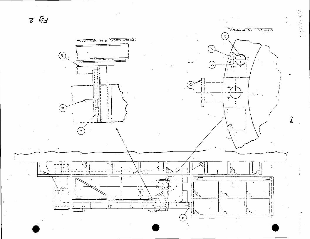
'. . ...__ _ _.,, I . ' ; .! I I I
__ ,...._..-~...., I I ,
I I I 1 i I
' I I
' ~J ~i
r--..-- I i:: I. I r "">' . 11·~ 1 ;.\ .. ____ . JJ\~ :t
~ I· . ~ I
/
8 \ r.----.-1.--l ~., .. ,, -_--:-it· i.-::-:;:-, ''0 i -'-.1 ! • .. : ;, ! b.- '.L---, IA I r"' .rj
.~ -H- .:., -..:· --~ i - - - - - - ~ ~- - +. - - -~ _:_ r::=::-- - -- --r-, -~ I . -- .. ~! =. =,.,..= .... ~ '~=~=::'.:::::::====~--=-'.~::..::1 ' t:'.::1 :.:~::::-:-=--:::;:' ==·: =='::::;::-~~, -~· - \ \ :~- ' ~Lli =-==r~-c__-;;-1 ~0~111 --:---'--1 ' \ - ~ ; ' . II - - .:- - -,. - ~ ~ , I I ,_ "" p·._, t
,\ __ -:-- 'I 1 . - ~-. ;~; -~ - Q: :f~ ".~---,,, 'i :::--~====.~I l:r. ~:....... ~ ! , ·--, I ,__, ~---....--- ;~· . ! , I~ . ji I: -~~~~:::;;:---.~ __ : __ • .J1 Ii ,, 11·
' , ·.· :--:.:-1 '----":iJ; L_ ;:.-,:..... I . . - - Ii i :- I . . ~. -;l '~ _,_ ,- -.- J .J , ,. h. I ; . ;-,;-...L--'---~---'---~ .,_ __ _.-: ··----'· I .•~ • ~ ' .:;:...:·:$..~---~ ~ 1. • 'll ---/ :, .,.. ==-------~ ·-----' (~\ i_
~
' ,. , I
If)
I i::i
---'"":: ....
·-~
... . -.. . . ·-, -~-
·-.
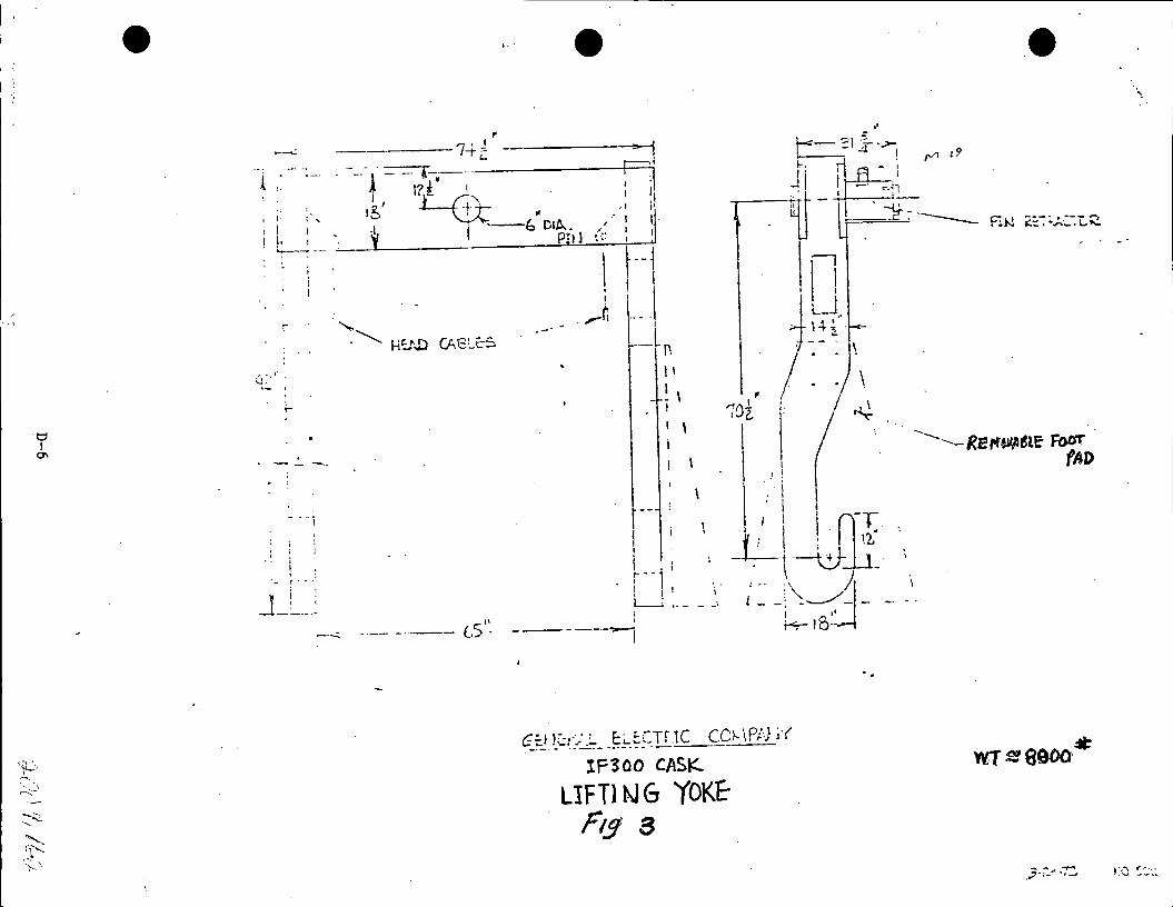
A ,:
r
u~· '· ·- . I t-
- - - i
- r - -
Ji ' '. I ____ ..
---::. ---- -··-- ts'' _
•·.
n I ~l·. 1' ~ -
I;~-: \
, . . \
1oi \ ~
. l ,! ( : I
I \
l I I j ~T I . L\__iiL 12: r··1· I • --~- .
1 ! '. I~•-- - ~. {; ~ _\\_/j ______ ____; I •' - -
I t<:-15--
c;-:.1 l~- -·. . C.· • ·--~- ·_'-~_ .... ...:..~- -~L.=(-Tf"JC CO' ·1p:.l ··( ---- ---- r- • ~·J J
IF '3 00 CASK. ----
llF Tl N 6 YOKE F1.9· a
.e
R>J ;:_:.- ~ •. --, ...., _, J"\-•W~
...... -- . .......__ REl'f~~lE' FOOT · fAD
, ..... ' •... -- .... .- ......

2. Remove covers by lifting straight up with hoist located on the west
side of equipment hatch, second floor reactor building. (Cap. 5 tons)
Note: The covers weight approximately 400 lbs. each.
3. Place cap screws in equipment box and store covers on skid.
4. Remove lock wire from drain and vent valves.
3.3 . Atta.ch Lifting Trunnions (Fig. 2)
3 .3 .1 . Remove bolts "M", pin keeper 11 N11 and pin 11 P11 securing closure
end of cask to skid frame on each side of cask.
J.J.2 Remove each of two lifting trunnions from equipment box with hoist
used in 3.2.2. and insert between lifting rings above skid saddle.
Secure in position with pin "P", pin keeper "N" and bolts "M" removed
in step one above.
Note: Each trunnion weighs approximately JOO lbs. This equipment
was designed to use the same pins for securing the cask to
the support and attaching the lifting blocks to the cask.
This precludes the possibility of lifting the cask without
removing the pins from the cask support. Each pin is ma.de
high strength heat treated material. Under no circumstance
shall any attemtit be ma.de to use ~ubstitute pins •
. 3.4 Attach Lifting Yoke to Crane HoOJk (122 ton camcity) (Fig • .,)
Note: Lifting yoke is· stored on refueling floo~ - 613 1 elevation.
The six inch diameter pin must be retracted to attach crane hook to yokeo
3 .4 .1 Attach short handle to the lock bolt socket. Loosen lock bolt
(M-19) by turning counterclockwise until resistance is felt.
3.4.2 Apply pin actuator socket to pin actuator shaft and turn shaft
clockwise until pin is fully retracted.
D-7
. -
3.4.3 Lower the (125 ton cap.) crane hook between the two channel sections
so sister hook center hole is aligned with yoke pin.
3.4.4 Turn the pin actuator shaft counterclockwise until the pin is
fully inserted.
3.4.5 Tighten lock bolt by turning clockwise.
3.4.6 Remove lifting yoke foot pode (Stand) before using yoke.
3.4. 7 Establish communications between 125 ton crane opera.tor and personnel
on 517' level directing crane movement. An operator in communication
with crane operator and personnel directing operation will be stationed
at the main breaker supplying feed to the 125 ton crane. Any deviation
from presc'!'"ibed routes, etc., will result in the operator trippin~ the
breaker.
The cask will not be allowed to be suspended during periods of inacti
vity and can only be resting in the following places: horizontal on·
the cask car, vertical on the decontamination pod or vertical in the
pool.
If during the above conditions, the crane is attached, i.e., .hook/
yoke/cask, the crane must be locked up (main circuit breakers
included) to preclude any accidental movement by unauthorized person-
nel.
3.4.S Move 125 ton crane with lifting yoke to equit:ment hatch and lower
to the 517' level.
Note: Before movement of cask commences, only autho'l'"ized
pers.onnel essential to cask movement and normal plant
operation will be allowed access to the reactor build
ing. Constant safety must be stressed to personnel in-
volved in the cask movement.
D-8
....., " ·')( i J / 1,/ if t)(.,./ i lb';
3.5 Attach Li~ing Yoke to Cask
Insure that car is properly spotted and chocked.
3.5.l Move crane hook/li~ing yoke perpendicular to axial center line of
cask until yoke hooks are between trunnions and top of cask with
open side of yoke hooks toward bottom of cask. (Important!)
3.5.2 Lower hook/yoke, guiding yoke hooks astraddle cask, until open
area of hook can accept trunnions.
3.5.3 Move crane hook/yoke laterally toward bottom of cask until yoke
hooks are directly under trunnions.
3.5.4 Raise crane hook/yoke until yoke hooks have fully engaged each
trunnion.
3.5.5 Stop lift and ascertain that yoke hooks are properly engaged on
each of two trunl'.lions.
See S&L Drawing # B-600 attached hereto.
3.6 Raise Cask to Vertical.Position
J.6.1 Check skid and cask to ascertain that there are no encumbrances
to rotation of cask from horizontal to vertical.
J.6.2 Check car brake.and wheel chocks for proper placement.
J.6.3 With load line of crane vertical (plumb), start lift of crane.
As cask rotates from horizontal ~o vertical, move crane later
ally towa.rcf bottom of cask so as to keep the load line plumb.
Note: If space in hatch way limits lateral travel of crane,
it may be necessary to stop lift and respot car so the
cask socket trunnions will move toward the cente~ of the
equipment hatch. Change wheel chock location accordinp:ly.
D-9
J I ,/' .--· . (} _) tJ&O ·1 I l.1 .·

3.6.4 Continue lift, when cask approaches vertical (approximately 87°)
stop lateral travel until crane hook has full load of cask, this
will Prevent rocking at top of arc.
3 .6. 5 Raise cask to the 613' 611 elevationffe This is 2" above curbing,
etc., on refueling floor (613 1 elevation)
.3.6.6 Move cask from hatch to decontamination pad by prescribed route1•
See S&L Drawing ;Jc B-601 attached l1ereto.
* ~hould the cask drop through the hatch, the worst-case accident would be loss of the pressure suppression c.irnmber (torus). ,ls
called for in the Dresden Technical SiJecificati~s, i:f minimum water v0lume cannot be maintained at 112,000 ft , an orderly shutdown shall be initiated and the Y"eactor s'.J.all be in a Co.Ld Shutdown condition within 24 hours.
3.6.7 Close the hoods on the cask car.
Only authorized personnel will be allowed on cask car. Contarniria.-
tion must be kept to a minimum •
.3.6.8 Remove wheel chocks and release car brake •
.3.6.9 Relocate cask car in air lock with track mobile.
3.6.10 Set car brake and place wheel chocks.
3.6.11 Close inner air lock door and lock.
4. Prepa!'e Cask to Load
The cask has been flushed and cleaned at the reprocessing plant.
4.1 Notify Rad Waste that·they will be receiving water.
4.1.1 Wash exterior of cask with clean demin. water to remove roOd dirt.
4.2 Attach closure head lifting cables located in the equipment box, secure
pins with cotter keys.
4.3 Loosen all closure nuts until complete disengagement of nut thread from
the. stud thread is assured. Leave ail nuts in place in the closure head
sockets (of BWR closure only).
D-10

4.4 Attach demin H2o supply hose to sna.p-tite fitting on drain valve. "D",
open valve 11D11•
4.5 Attach overflow hose to snap-tite fitting on vent valve "V", open valve
"V". (An acceptable alternate is to use fuel pool water)
4 .6 Fill cask with demineralized water ( ~ 800 gal) through drain valve
(use fuel pool water).
4. 7 Close drain valve "D" and remove hose from snap-tite fitting.
4.S leave vent valve open with short length of hose attached to snap-tite fitting.
Note: Vent valve must be left open to allow for expansion of water
. after fuel assemblies have been loaded into cask. The snap-tite
fitting has a. spring loaded closure that closes upon disconnect;
therefore, a companion fitting with short hose must be left on
to keep the snap-tite open.
4.9 Attach tag lines to yoke. (Use nylon rope)
4.10 Lower fuel pool level by 2500 gal.
4.11 Move cask from decontamination pad via prescribed route,
to position directly over pool cask pad; stop at pool rail to remove
section of rail. Replace rail before lowering cask.*
See S&L Drawing# B-601 attached hereto.
* Should the cask drop over or near the pool, emergency procedures described in companion addenda E & F shall commence. Generating Stations l1nergency .!:'.Lan-Teen "pee. 6.2.A.4 c:c t.i.3 • .A. Nake-up for the fuel pool shall be initiated by 9pening manuaJly valve 1/:2-1904-5-27 and/or valve #2-1901-14 (condensate system and cordensate transfer system). The four tell-tale drains for the fuel pool liner shall be closed.
4.12 Orient yoke of cask in accordance with available space in particular
facility to permit ease of yoke and closure removal. (To be developed.
on dry run)
4.13 Place lights. View surface onto which cask shall be set to ascertain
that surface is clear.
D-11
{ /; I

**CAUTION**
Do not lower cask into pool unless
it is verified that the surface is
clear.
4.14 Lower cask slowly to bottom of pool. (See S&L Drawing /,!: B-602 attached hereto.)
Note: T_he first time cask is being loaded, index marks must
be made on both X & Y crane travel so crane hook/yoke can be
ret'l,lrlled to the exact position for replacing closure.
Also index cables indicating point when load transfers from
hook to pool floor and point at which yoke hooks clear bottom
of trunnions.
4.15 Stop down travel or hook/yoke when top or yoke hooks clear
bottom or trunnions permitting disengagement.
4.16 Mo,ve crane laterally until yoke hooks are completely disengaged from
trunnions (approximately 1011 ).
**CAUTION**
The closure cables are still connected
to the. closure and excessive lateral
travel of the hook will tip the cask.
Cables must never come taut while moving
laterally.
Note: Im ex mark cable at this elevation
4.17 Raise crane hook/yoke until bottom of yoke hooks clear top of truninions.
4.lS Move crane hook/yoke laterally back to center over top of cask.
4 .19 Slowly lift crane hook/yoke. When clo5ure cables become taut, the
closure will start liftin~ off the cask. Closely observe cask for
SDY tendencv to move .,.,"hile closure is be in!? lifted.
4.20 When closure is clear of cask, raise crane hook/yoke and closure out of
the pool. D-12

.e
4.21 Inspect the Gray lock stainless steel ga.sket attached to the closure.
4.22 If it is necessary to release the main crane hook for other work,
move crane hook/yoke/closure to yoke storage area and perform crane
disengagement as a reverse of that described in 3.4 (i.e., 3.4.6 to
3.4.1)
Note: Set closure on pedestal before setting yoke down on foot pods,
thus preventing SS ga.sket from being damaged.
5. Loading Cask
5 .1 Obtain list of fuel assemblies to be loaded and transfer procedure and
map (GE Provided Form) for the fuel basket. (Lists - EXP., WT u235,Pu239 )
. 5.2 Move fuel assemblies, one at a time, with fuel grapple from storage
rack to the cask •
. 5.3 Verify identity of assembly inunediately after placing it in the basket~
Record the fuel assembly number on the fuel basket map in the corresponding
cell space.
5.4 Continue loading until all cells are filled.
5.5 If crane was released for other work in step 4.21, then perform yoke
engagement described' in 3.4 (i.e., 3.4.l to J.4.6)
5.6 Replace closure, center hook/yoke/closure over cask per ind.ex marks.
Lower crane hook slowly so closure engages guide pins. Continue lowering
hook to index mark on cable. Cables will now have sufficient slack to allow
e. yoktengagement.
5.7 Engage Yoke with Cask Trunnions
5.7.l Move hook laterally (away from valve boxes) until hooks of yoke
vertically clear the trunnions (per index marks on crane trolley).
5. 7~2 Lower hook until top of yoke hooks clear the bottom of trunnions
(check irdex marks on cables).
D-13 c::-"I '"(flj /(,tr~.:. •/·(l .. <'l.

. e
5.7.3 Move crane hook laterally to index mark centering hook over cask.
5.7.4 Slowly raise hook-yoke until yoke hooks have engaged trunnions.
(Check by observing cable index and yoke hook position.)
5.7.5 Stop hook movement and verify that yoke hooks are.properly engaged
on trunnions.
** CAUTION** Should the cask drop at this point, refer to Paragraph 4.11 above and the notation following.
6. Move Cask From Pool to Decontamination Pad
6 .1 Place plastic drapes on fuel pool rails.
6. 2 Position high pressure water spray system to rinse cask as it emerges
from pool. (Clean demin. water)
6.3 Position Health Physics Monitor with radiation measuring meter to
meter cask as it approaches surface or pool and emerges. Ir radiation
streaming exists during lift, stop and lower cask until streaming
ceases. Ascertain cause and correct.
6.4 Slowly raise hook until cask lifts from pad. Stop lift and observe
rigging for proper engagement. Continue raising cask, monitor continuously I
as top approaches, surface or pool. Stop lift when top of cask is at eleva-
tion or pool curb.
6.5 Spray top of cask. Use clean demin. water and hard wands.
6.6 Spin a minimum or four closure sleeve nuts (sequence 1-4 per Fig. 4) full
down, hand tight ·plus 1/4 turn. ·
6.7 Continue raising cask from pool, slowly while cask is being washed with
high pressure spray •
6.B Move crane/cask via p!"escribed. route to the decontaniination pad.
See S&L Drawing # B-601 attached hereto.
D-14

6. 9 Lower cask onto prescribed spot on decontamination pad. Leave yoke
attached to trunnions and crane hook unless crane is needed for other
service. If crane is needed for other services, perform crane disengagement
as a reverse of that described in J.5 and J.4 (i.e., J.4.6 to 3.4.1)
7. Prepariniz Cask at Decontamination Pad
7.1 Apply the balance of the closure retaining nuts in sequence 5 through 32
full down, hand tight plus 1/4 turn (Fig. ~). After number 32 has been
tightened, again start with number o~e and continue in the same manner
until all nuts are torqued to 450 ft. pounds in 100 ft. lbs. increments.
7.2 Pressure Test Cask ·Fig. 5
i. Remove hose from valve "V'' and place 400 psig pressure gage on valve
"V" snap-tite fitting. Open valve.
2 •. Attach hose from pump "P'' dischal"ge to cask drain valve "D".
3. Attach supply hose from demineralized water valve "S" to suction of
pump "D". Open valve "S".
4. Start pump, slowly crack open cask valve "D". When pressure reaches
200 psig ±. 5 psig, close valve "D". Stop pump, and disconnect hose
from cask drain valve "D".
**CAUTION**
Relief valve could operate and discharge contaminated water.
5. Record pressure. Hold for ten minutes. If pressure drops, determine
cause, correct and repeat test.
**CAUTION**
Relief valve could operate and discharge contaminated. water.
D-15
:::i ( ( I ·1 , t ,_ ,;• / e;·- ·...' u' ' ,,

• I
e·
I I I
/ I I
·"·~. ,...-..., I ( ii
L . .,. I ' .-" I i
,-..._.,., ... ·~-~,
/··-~{<:_) ··--. ' .. --· ··-··--" ·~ .~ _,,. ..
...... ,
,.,..,·
.•· ..
·.·
·.,--.... : ... _.., -·- ..
/,~·.,.'. ' ·"· ... :' ·. ·' "':
'· '··-~...> '
'·
.. , \' ~)' .;
___ J ... ·-·-\ r· '. ! '
I I / . .!. :' ... /
I / ,, •• ..•. ., ...... , .......... _, ............. _ ................... -~.~ .. --,-/ (..)(~~,.: .:1/ .. ~. ~\ ~
.,.. ·-·-\. .... _,;
' .... •\ . . • 4
---J.:. .. --:--·-·• '.~ ... - _ ........ •;•.· .... ~--·-·•c•-.....~--":"
,':~. \·:) .J
.-~· ..
. ·1·,,._· - -.. •, /') :·~. ::...· '-' ·-.--... ·
D-16
•'
•.. 1.3.?..:;
\
---1
·J,S; ,,
'·
.:
' "
,•
i'
''.
'' . . -··
I I,. ' '<A.· · .. ·:·
-.. : .......... . . .: ·': 't \; ~';• :r' ,. l ... ~ \
····~·,_ ..... :··p\ f
·,'
i
'\,.: ,:.
r ·' ·'

7.3 Flush Pool Water From Cask
1. Close vent valve "V" and remove pressure gage.
2. Attach drain hose to vent valve "V'' snap-tite, drape opposite
end into fuel pool. Open valve "V".
3. Attach supply hose from demineralized water supply to cask drain
valve "D''. Open supply valve "S"; open valve "D". Flush for one hour.
4. ~ample.discharge at start of flush, at 30 minutes and at one hour.
Flush can be stopped when sample·indicates flushing is no longer
effective.
During.steps 6.6 through 7.3 decontamination work should be performed l simuntaneously.
Warning: During the flush o~ration, care must be exercised to avoid
cask draining dry. The water in the cask is a neutron shield.
If Rad man is not present, personnel should have monitoring
equipment equipped with alarms.
Many reactor fuels are a moderately strong neutron source.
5. Discontinue Flush
Close cask drain valve "D", and dernineralized water supply valve "S".
Remove supply hose from cask drain valve "D" and attach a drain hose.
6. I
Adjust water level in cask. Close the drain valve and the vent
valve. Remove hose from vent valve.
7. Raise fuel pool level to normal.
7.4 Start Temperature Pressure Monitoring
7.4.l Place pressure gage on vent valve. Open valve.
7.4.2 Connect thermo-couple leads to a temperature recorder. Start
recorder printing out cask cavity water temperature, barrel
water temperature and ambient air temperature.
D-17
• "' C'.'1 I , ·;· ·_·_.·_, . ,,.,.,_;(/() . I (:/ .
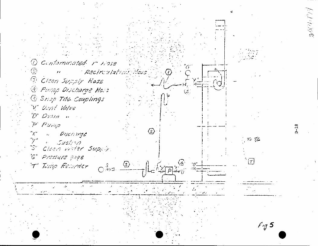
l. I
r-. J • '. \_!.,./'
;--;i\ \~I
(]_.; --·v·· 'D''
"t ,, y
··.·
...........
. . """~ ~· . .
. -~~-~.-~-:: .. : .. 4- .... •' . •.
, .... -· ... . . . .
~ ..
,, , .. ··· .. /' . · n-?,,.1·,,.._ .. '"/'"""'/·'··' ··/:·o..:..:.·; ;< ,_ 1.,,, r L ... , .,., I ~ • .. ··.. . .. ..... .
P.-', r~i .. ~ L·' •',. f' j../
. I
1/,./,, / vt-·,, v .!-
0;-·.:1/// ,,
p !..i' i ;i ,:._2
'
..- ' • . .) ,;/ ~ i :-- ::· /? /•
C /,_;.· -'f ,.r; ;·..,. '•!" I
. . ..... ,,/ c, ,.,,, If''/,.-"
")/I.'"").- .. ... J'•/-';'- I I~ '
· ...
- •,
.-n ~ I :
l ~>
;
' I
J ·.. ''· '-' . ·1 / . \1:'
\,3,) ·. . (Le· I"',. 'x·· . -~--1) r7 pj1· •Ll
----- ----+-·--- -~-~ -·--·----· - ---- - -·-----···---·--..,..-----------·--···· ~· . ·~ ..; ·· . I
·•. ..,·._,, .. ,,_ : -~ .. \ _., ~·:-;, .. ~·~ .. ·..,, ----. ~ --·--~1-. ~~-;~-~~; :.-~:: :--··. -~--····--- ·-· ·--·--·--·----
···. . ,;_ ·.· .. -.... · ....
•';_. .
~--:
... ;:_ .•
. '"\'··•
.,
o __ - --!..
! •• II I . D ---l.-----·---· -
. :.'~ ·---+- ; ----1
I ---'-···----·--
I . ... ~- ~--· --~- ______ _,__.,_
,.:
. ~ ....... ·.J>· • ••• ,. •
00 r-l I ~
--~ ...... ~._
... _. ~:::::.
ri)

7.4.3 Record cask pressure ho~rly (Data sheet)
\9. 7 .5 Sample Cask Water
Cask cavity coolant shall be sampled:
7.5.1 One hour after flush.
7.5.2 Eight hours after flush.
The samples shall be analyzed for total isotopic activity, also for
strontium ·90. Results shall be plotted on log-log graphs and activity
extrapolated to 100 hours.
7.6 Smear Cask
Surface of cask must be decontaminated to 2200 cpm/100 cm2 or less
average over each square m~ter of surface.
7.7 Complete Check List
7.8 Remove Temperature Monitoring Connections
8. Return Cask to Skid Frame
** CAUTION**
Should the cask drop at this point, refer to Paragraph 3.6.5 above and the notation follm,ring.
The cask will normally hav~ crane hook with yoke a~tached to the cask. If,
however, the crane hook has been released for other service, then the crane
hook must be affixed·to the cask yoke per item 3.4 and the 'yoke re-engaged to
the cask trunnions per· item J.5 of this procedure.
Personnel rem<?v:lng railing are required to wear safety line.
8.1 Remove section of railing at the fuel floor equipment hatch to allow
cask to pass. ~eplace railing as soon as cask has passed through ·rail
opening.
D-19
>G....00"'-l I I 't ~·

. e ~ .
8.1. l Assure that outer air lock door is closed and locked •
8.1.2 Unlock a.Di open inner air lock door.
8.1.3 Remove wheel chocks and release car brake.
8.1.4 Relocate ca.sk car in reactor building to proper index marks on
rails (car is properly located)
S.1.5 Set car brake and place wheel chocks.
8.1.6 Open the hoOds on the cask car.
S.2 Raise crane hook until bottom of cask can clear all obstacles on ,
prescribed route figure 5, to equipment hatch.
8.3 Move crane laterally to center cask over equipment hatch.
8.4 Lower cask to skid spotted on car/trailer under the hatchway.
S.5 When bottom of cask is approximately 611 from the skid socket, stop·
down travel and adjust lateral travel to center cask bottom over trunnion
socket.
8.6 Continue down travel of crane hook until cask is seated in socket and
starts rotation into horizontal position.
S. 7 As cask rotates, the crane hook must be moved late?"ally to keep the load
line vertical. A lateral tl"avel of 13 1 3" is necessary; if this is not
available, the skid must be repositioned by use of track mobile to prevent
load cables or crane from striking the combining or the equipment hatch.
Continue down travel of crane hook until cask is resting on saddle.
8.8 Disconnect yoke from trunnions, raise yoke to 613 1 elevation and store in
designat~ area following reverse of 3.5 (i.e~, 3.4.6 to 3.4.1)
9. Secure Cask to Skid
. 9~1 Remove trunnions and store in equipnent box provided. Reverse of 3.J.
The tl"unnions are very heavy and must be handled with appropriate lifting
hoist.
D-20 t .
';) CJO? ' I '/r.:_:
.e l '
9.2 Insert pins "P" (each side of cask) through lower holes in top lifting
rings and skid saddle. Apply keeper "N" and bolts "M". Lock wire bolts
"M" together.
10. Secure Valve Boxes
10.1 Lock wire drain and vent valves closed. Ascertain that snap-tite
coupling covers have been replaced.
10.2 Replace valve box covers. Torque four cap screws on each cover to
approximately 20 rt. lbs.
11. Position Air Ducts
12.
11.l Grasp the duct support tube and move each duct towards center or car limit.
· 11.2 Turn lock pins, two on each side, off guide beam and press down into
lock slot.
11.3 Replace snap on couplings, one on each side, connecting ducts to the
ran exhaust.
Start Auxiliary Cooling System
Operation of the Duetz engines within the react.or building is permissable;
however, there will be a slight diesel odor. If operation is necessary before
car is moved out or reactor building, attach exhaust hose to valve vent in
reactor building wall.
12.1 Disengage Clutch.
12.2 Set speed control to 1/2 load position and press starting fuel allowance
button once.
12.3 Push in the switch box key, red charging indicator lamp should light up.
12.4 To preheat the engine, pull heater p~g starter switch up to the first
stop. The normal preheating time is 30 - 60 seconds: however, during
this operation, check to see that the heater plug indicator slowly takes
a glow.
D-21

Note: If engine is warm, preheat is ·not necessary.
12.5 Pull the starting switch out fully. As soon as engine begins to fire,
release starter switch. Do n<>t, run starter motor longer than five
seconds. Do not engage starting motor while crank shaft is still rotating
from previous start.
12.6 Cut the speed back as soon as engine is running normally. The charging
indicator light and the heater plug will have gone out.
12. 7 Observe that oil im.icator gage pointer is in the green field; :H' it drops
back to the red' the engine must be stopp0d e
12.B Engag~ clutch and increase speed of fan to 2000 RPM.
12.9 Observe general operation, such as drive belts, fan bearing vibration,
etc. Report any abnormality to GE at MFRP.
Repeat steps 1 through 9 on unit two.
13. Close and Secure Hoods
e 13 .1 Grasp the operating levers of the large hood (one on each
side) and push toward bottom of cask. Each lever will rotate approxi-0 .
mately 30 to lirt the hood onto rollers. Continued push on levers will
cause hood to roll to the full extended position. Release levers to
lower hood off rollers.
13.2 In like manner, ~ve the center hood to its original closed position.
13.3 Turn the six locking_pin handles and press down into lock position.
13.4 Insert retaining pins in the front of the large hood.
13.5 Apply pad locks to each of six locking pins of item 3 above.
14. Move Cask Car Into Air Lock
14.1 Remove wheel chocks.
14.2 Place one set of car chocks on track inside of outer air lock door as a
·~ safety stop to prevent car from striking air lock door.
D-22
14.3 Release car brakes.
14.4 Move car into air lock, using track mobile.
14.5 Set brake and place wheel chocks.
14.6 Close inner air lock door and lock.
14. 7 Complete check list, bill of lading and dispatch car.
D-23
. t I' ..... ·1 (' ~ ~· •1 I ;f I .~ ,\
, :;. VI ' ~ .t ~ 1

(::
. ,. &
;•
" ,. !:
~-: J··. ;i
iL ,! ;r ii-'• " -~I
II jl.-
ll-'1 !i
"i•· ·~;
·JI· - ' 11 .
'J.
!~ Ii l' ,J
-ii I. i.
1.4
~ ' .-
.?:l1
~: •f :.t: ~ ·1· !'
-· •
.. '
•
•
7
r )~_
PQOCCDU~£
NDTG.• .............. OvT&Q (>'OC.i;tS. M4'f .. o"! e& =~ .. llD &T T"°ll ~A ... 1!. Tout:.
91~ 1.oPll."" OJT•Q coons STl.P tt. P0:!.1T10"" ~C""'40B11..;: a. .-1,,1ti.., :;:.a&q, h"r.>lf'lS.!.N
"-1.,.ell &. =--·!!!~ ~n:'"'IA.~ ST•~ 3,c...:i~e. OuT•Q oocq.:i. ~Tao .... 9AC""- TR•C. ...... toe.11..Cl .. •...i~i.. CA5l TQ
OvTE.llil o:o~> ~TllP 5 oP•N l .... Nli.1:1 ooo-=ts. 5'1!• fi,. TR4CKWL0BILE PO~\TtO ..... ~ .. l.llll.. ..,;a~
Uf'.IC>&l:I M.<::t.TC.M. . S"nlP "1· ~T C•Q eq"'""-i.~ &. P\.AC• ..,,..i.6\. CHQC:K~. ~T&D ll "-'"""-°"0 ~1,,.e.._. . ATllO. 11r:.vaq_sa ST•PS I T .. Clu " TO llllMOVl!. ~ ~llOlo\ lllli•CTOR 1!!11.;11 ... C1N~.
SECTION A-A
&00 Ali.ICI &.J~ CVCT «5IE!1..5~1'-t'"'I," !lltii ~,..1"'°'•2.l:l0"1'6 .... c 6 e:.L. 15~· • .,~!.· ..... ~ .......... ,.z.l·.foaet
..
4
0
PARTIAL PLAN "AT EL.5171·6' (AL.T. NO.I)
..,._.,.
------~-~---s' -----~ -·--·----- -------_--- .. ----------- -- -
.. •D~• 00// . . . &J~ C.VC"T
o-..
® ---------------------'
SECTION e-e ('e-..,,,)
3
SECTION C-C (0-..COJ
,..,..--~· LJ ....... Ml
"'' .... _, ~ . .
PLAN o a:
3
---~---""T4!>
OUT\.llN& or QBhWllA.I.
REFERE"ICE CR.A.'WINCiS
1' 11'"300fUELCASK l::r~~~~jL.c~OING LAYOUT SH. I UNIT 2
PRESDEN MJCLEAR POWER ST. !'COMMONWEALTH EDISON CO. ,, CHICAGO,ILLINOIS
'-~
D
•
.:J.rJo / ! I (\t) _I
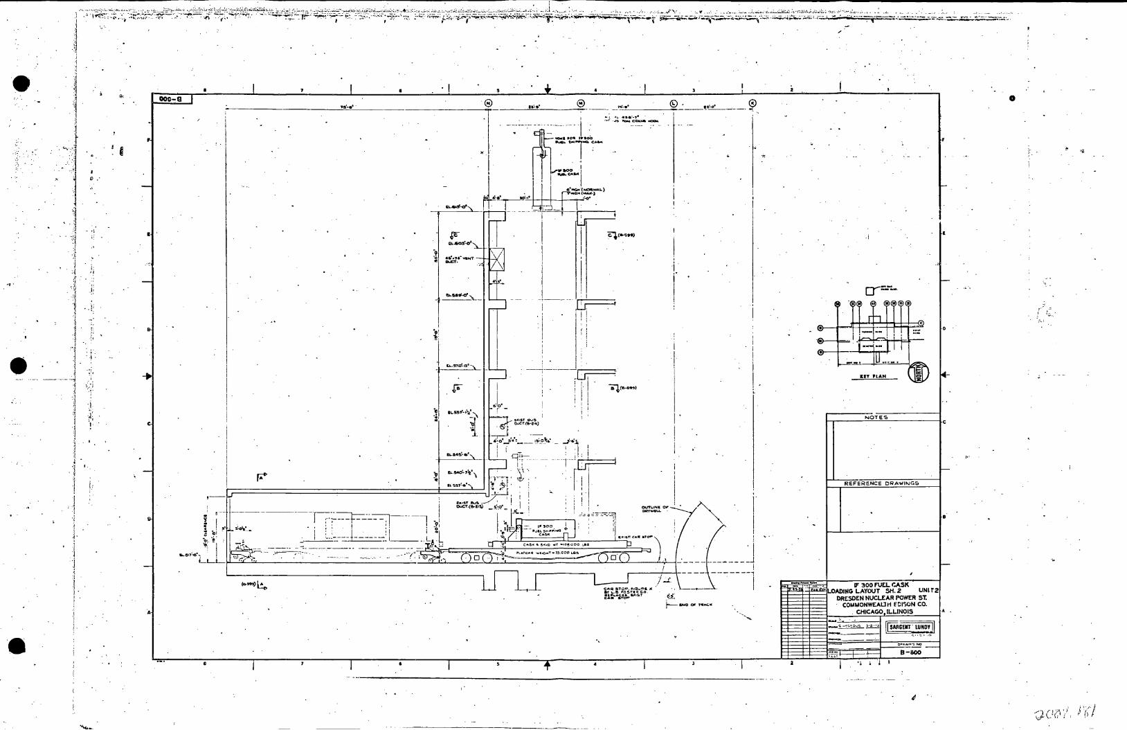
I,·.
..,.
j j
...
j. ' ' ·1 l
l .;
:i , I i. !
J.
•
i
, I
I .
i.: ,,
c
I.
. I
•.....
I ~ ru..so.s'-o'
I I
i
4'3~ I I
-'-. ---·
i
I I I
:Z'
-----'
I
~~·-F
~. ~~-·~i
l'S'·•' ......... .,. ,..,.F • ..:"Oo f'QlolCQ .... llCCICllfo
Cl.C•9H)
I
91 I i '
I µ ei,ce-!W51>
/ .. L
.,
·i r I !
i I ! i
I
I I i
--~
·• I
--------1
.j
f"""Y"-LJ --·-·
UT PLAN
REFERENCE DRA'WING&
0
;'-,!
I

-~;:{t;::'~:l~~~~.~~;~-:~;~:" ... ~~.:.:.:::'.:.L:.:.~~..:..~~.:~~-'=~~·~~~~;~~;.::~~·;:~~:;.~~;~~~~~;::J;~~.::.~.~~:~:.:.,::::::,:,:::;~::~~~;:\~·;.':~-.:~._:;~~:~.~;~~;:~;;·;.;.;~·~;._~,~~:~.:.:::-.;,~~:,~!~-~A~·;.~~~~~::·~:::~:·:,~:~::.~.:· -
..
I:.
.\
- i ----....j 1·
j .. i t :
., -j
i ' ! >.
' ·~ l - -~ ·- - . ; .
;j j ·l .i .1 . , ·j: . 1-. ~ ' : ~ .
;; . ;1 .. .. : .
i· -; ..
I
-
-
•
-
,,
' 1 I • I 4 I I ' I
m-e
~- C'l (~ ~~ -'" '~ Q~1 .. .--~o· --+G~_ . f: ~ ... , .. .,.. ~ . =-1. ____:_~ l------t----0'-.-_,,--+---. ---\--.1'''"!!.''::·,£:!'.'... ___ ---+---o-:.,.-.~-=· -~+---....,-..-: . .,.:---+----:-a6:::-.. -::::~.:---f~-------_--:->.f:-.!.-::::.,.:---i_---;:a:;-4 ... -:::: ... ;-:-T-~ .. '-'-";~;-::.-'.E~.===-1!1-__ -~. '-e~ 1•·-11· =-=i. . . i---~~E{------~~-----H=, .. ~··----~~- ,- I
---r-----+---------+--1 ---+-1 --+----1 -t-----1 ------+--+---. -~r----r-----_ 1 - 1 I -1
I 1'
~===~===--==-==t~-==--==--==-=i=..-==~-====i==:====i====-===l=========F==~-===t========~~-==--~=t=--==-==-~~==-~-===~1-H<®~
I
--+-!' ----+l------+---1 ---.--+I--
I l
(~ (~(!) «!> i!l<·~ Ii) "'
rn .r. ~·~-+~J!=l~=!=-=t:~~~~~· I,_,,.. ,, ..
I l ; I 1
• .!!. r-"}--t--- ·°:'"'" ·-· I I \!')
µ• ~--·--~··~ .. -~; -
IUY PIAN
I
PLAN AT EL. ~1?1-0·· ·
I ' ---t:=:
l I I •f "j'"j I
! I
.b ·iii ..
b
~I I I I
' -© i I
~· ·:
B-llOI
-
'-.

i
·J ' .,
-----~
1 i .J ·1 4.
J ··':i
) , . ·1
. Q
: ,,
i, ; 1;
1: , .• I '.
=.j; . J ' J . ,' ·3 .1
1 _! i '' .. '' ·,' '. ; I
il '.I ' ~
'' ',. : 1· ·. ~.
209-11
f
.,
r 11~9'" t J.1·9'" 1 '!>
r
-------
l8f-· -~1 r.
•'rj ! I 1 1 I
<::' j~l" 111 i 11
•. ·~ ... ~. ~. ::- ' I - . I i i ! I
!
'{,{, ::1}:/( ----------.·· .. ,_ ..... . ·: . ·~··-·-·------.... -
~~~· -·_-:._ .. _ . :~ .. ;.::~:. ~
!~ i
'.i\:?'~L~~ '~-I ....... · ·.·· .. "'
0 • _· •• ~ ~· :". . . . . ~ . . -·. -~ ~ ....... .
: • ~ . -~ -.. __ : :t
SE.C.TIOC\J. 6· B (•·wall
I •
,•
r .. ... I
SECTION A.-A C•· ,., r
OETi:>.IL •c s..:.-..:,.a:\1,•1'•0°
'
t.JOIES
If" 300 FUEL t:ASK u:w>ING LAYOUT SECTIONS UNrr 2
DRESDEN NUCLEAR POWER ST. COMMONWEALTH EDISON CO.
CHICAGO, ILLINOIS
:.:·~~---,= .. ~-_"'~---~~ _~, =··_.-i, ~~-SAR==G=EPIT=;=P#!]=_~=~YQ=
B-S02
· .
...

e.
S E C T I 0 N E

December 19, 1972
To:· Shift Engineer or Foreman
Subject:: Dresden GSEP Drill
A spent fuel shipping cask was left suspended on the crane over the Dresden 2 spent fuel storage pool while the fuel handlers went to eat lunch. Upon investigating a low level alarm, it was discovered that the cask had fallen into the pool and the pool water level had decreased six feet in an uncontrolled fashion. The pool contains spent fuel assemblies and the water level is now decreasing at a slow rate {Approximately 2 ft./hr.). A small crack was observed in the lower portion (floor and/or lower six feet of the wall) of the pool liner. The leaking water is deluging the Reactor Building Closed Cooling Water Temperature Controllers and Reactor Protection and Instrumentation Rack 2202-5.
The fuel pool cooling system is out of service for repairs to the skimmer surge tank outlet valve (2-l901-62); the ski~.mer surge tanks have been drained in order to work on the valve. It is estimated that it will take an additional six hours to repair the valve and one more hour to get the system in operation.
Mr. R. Lemke and/or Mr.· G. Wagner initiate, interpret and observe the drill. when this letter is presented to either the Shift Foreman by Messrs. Lemke or Wagner.
will be present to This drill will start Shift Engineer or
Original Signed by F. Ac Palmer
FAP:ejk E-1
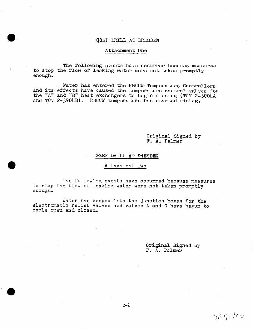
•• GSEP DRILL AT DRESDEN
Attachment One
The f'ollowing events have occurred because measures to stop the flow of leaking water were not taken promptly enough.
Water has entered the RBCCW Temperature Controllers and its effects have caused the temperature control valves for the "A" and 11 B" heat exchangers to begin closing (TCV 2-3904A and TCV 2-390413). RBCCW temperature has started rising.
Original Signed by F. A. Palmer
GSEP DRILL AT DRESDEN
Attachment Two
The f·ollowing events have occurred because measures to stop the flow of leaking water were not taken promptly enough.
Water has seeped into the junction boxes for the electromatic relief valves and valves A and C have begun to cycle open and closed.
E-2
Original Signed by F. A. Palmer
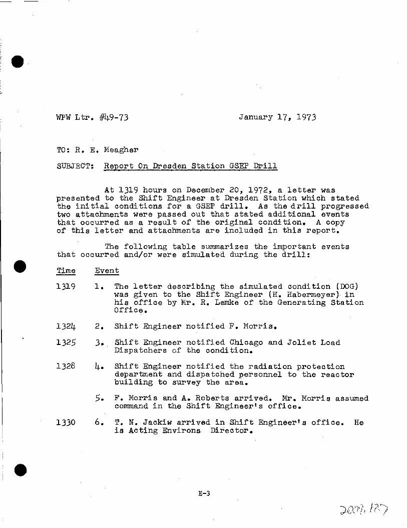
WPW Ltr. #49-73 January 17, 1973
TO: R. E. Meagher
SUBJECT: Report On Dresden Station GSEP Drill
At 1319 hours on December 20, 1972, a letter was presented to the Shift Engineer at Dresden Station which stated the initial conditions for a GSEP drill. As the drill progressed two attachments were passed out that stated additional events that occurred as a result of the original condition. A copy of this letter and attachments are included in this report.
The following table summarizes the important events that occurred and/or were simulatea during the drill:
Time
1319
1324
1325
1328
1330
Event
1. The letter describing the simulated condition (DOG) was given to the Shift Engineer (H. Habermeyer)· in his office by Mr. R. Lemke of the Generating Station Office. -
2. Shift Engineer notified F. Morris.
J. . Shift Engineer notified Chicago and Joliet Load Dispatchers of the condition.
4. Shift Engineer notified the radiation protection department and dispatched personnel to the reactor building to survey the area.
5. F. Morris and A. Roberts arrived. Mr. Morris assumed command in the Shift Engineer's office.
6. T. N. Jackiw arrived in Shift Engineer's office. He is Acting Environs Director.
E-3
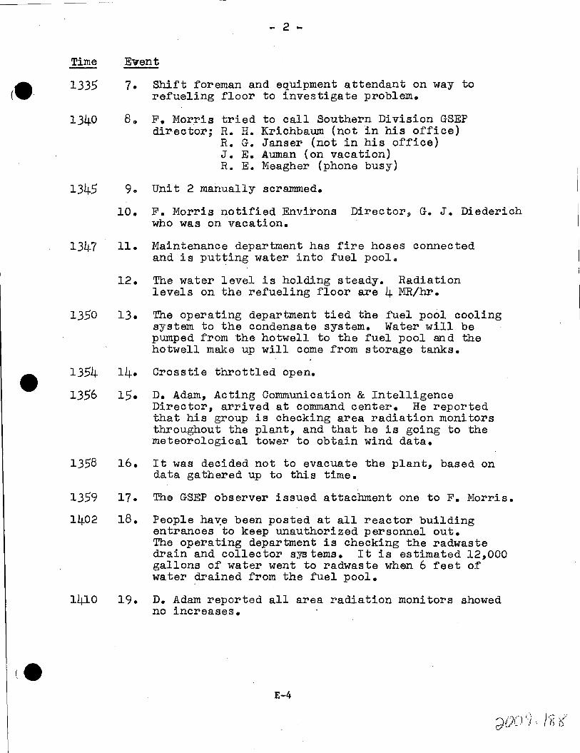
- 2 -
Time Event
1335
1340
1345
13~-7
1350
1354
1356
1358
1359
1402
l!.µ.O
7. Shift foreman and equipment attendant on way to refueling floor to investigate problem.
8,, F. Morris director;
tried to call Southern Division GSEP R. H. Krichbaum (not in his office) R. G. Janser (not in his office) J. E. Auman (on vacation) R. E. Meagher (phone busy)
9. Unit 2 manually scrammed.
10. F. Morris notified Environs Director, G. J. Diederich who was on vacation.
11. Maintenance department has fire hoses connected and is putting water into fuel pool.
12. The water level is holding steady. Radiation levels on the refueling floor are 4 MR/hr.
13. The operating department tied the fuel pool cooling system to the condensate system. Water will be pumped from the hotwell to the fuel pool and the hotwell make up will come from storage tanks.
14. Crosstie throttled open.
15. D. Adam, Acting Communication & Intelligence Director, arrived at command center. He reported that his group is checking area radiation monitors throughout the plant, and that he is going to the meteorological tower to obtain wind data.
16. It was decided not to evacuate the plant, based on data gathered up to this time.
17. The GSEP observer issued attachment one to F. Morris.
18. People ha~e been posted at all reactor building entrances to keep unauthorized personnel out. The operating department is checking the radwaste drain and collector systems. It is estimated 12,000 gallons of water went to radwaste when 6 feet of water drained from the fuel pool.
19. D. Adam reported all area radiation monitors showed no increases.
E-4

•• Time Event
1411 20.
21.
1412 22.
1417 23.
1418 24.
1422 25.
1423 26.
1424 27.
1425. 28.
1428 29.
1436 JO.
1437 31.
- 3 -
Operating department put 2/3 RBCCW heat exchanger controller in service (because of attachment one).
The GSEP observer issued attachment two to F. Morris.
Quick repairs to valve bonnet 2-1901-62 (skimmer surge tank discharge) have been completed.
F. Morris called F. Palmer and gave him statuse
2/3 RBCCW pump put in servicea Electrical maintenanoe proceeding .to electromatic relief valve junction boxes to stop inleakage of water (because of attachment two).
Mechanical.maintenance placing 3/4° sheets of plywood against crack with jacks.
Junction boxes covered with plastic.
Fuel pool system back in service.
Radiation Protection checked out second and third floor of reactor building. No dose rate problems for maintenance person.riel making repairs.
Storage tank level decreasing. Estimate decrease to be 800 gal/hr. in approximately 1/2 hr. (after completion of temporary repairs to fuel pool).
Radiation Protection persom1el posted at gate house. They are checking individuals on the way out, and not allowing personnel into the station. Surveys on 613' elevation show 4
6MR/hr. The activity
of the fuel pool water is 3 x 10 p Ci/l.
Leakage from fuel pool decreased to 50 gpm with plastic forced into the crack. The condensate make up pumps are running. No need to shutdown other units as long as enough water is available.
The maintenance department is wearing whites, rubber suits, and supplied air hoods during repairs.
1442 32. Electromatic relief valve junction boxes, wiring, and D2 RBCCW controller is dry and meggered satisfactorily. Putting equipment back in serviceo
E-5

Time
•• 1444
1450
1503
1507
le 1543
'1620
- 4 -
Event
33. Maintenance installed a 1/4" rubber gasket behind plywood. Expect leakage to stop in two hours.
34. Environs group has wind data.
35 ft 125 ft 300 ft 400 ft
- s 180° s 195~
- s 200 - s 210°
- 3 mph 8 mph
- 7 mph - 6 mph
35. Technical Staff contacting NFS to find out availability of a cask to remove fuel from pool for a permanent repair.
36. Station operating and maintenance personnel participation terminated. The station condition is secured.
37. In an emergency NFS could supply the station with a cask in one week. Moved command center to A. Roberts office.
38. A. Roberts stated the fuel would be removed from the pool and he would contact Engineering for repairs.
39. The plant would not be;started up until SRB and MRB approval is received.
40. Lost more water than originally thought from fuel pool leak. With actual conditions of radwaste at the time of the incident, it would not have been able to handle all the water. The calculated loss of 72,000 gallons (much more than the 12,000 gallons thought earlier) would have had to been temporarily stored in the torus basement. It would amount to appro.ximately 5" of water on the floor. The water tight doors would have to be kept closed and the area closed off. The sump pumps would be run manually at a rate so that radwaste could handle the water. After all the water is gone the torus exterior and floor would be decontaminated.
41• S & L stated the pool cannot be structurally damaged. They suggest not draining the pool, but sending divers down to cut out the damaged section of liner. Use grout to repair concrete then weld a new section of liner in place. Estimate job would take 2 weeks.
E-6
Original Signed by W. P. Worden
) O"I!. fl q() d. ,t_J /1 r:v
'
+
S E C T I 0 N F
(J.O(Yj ; I I' I
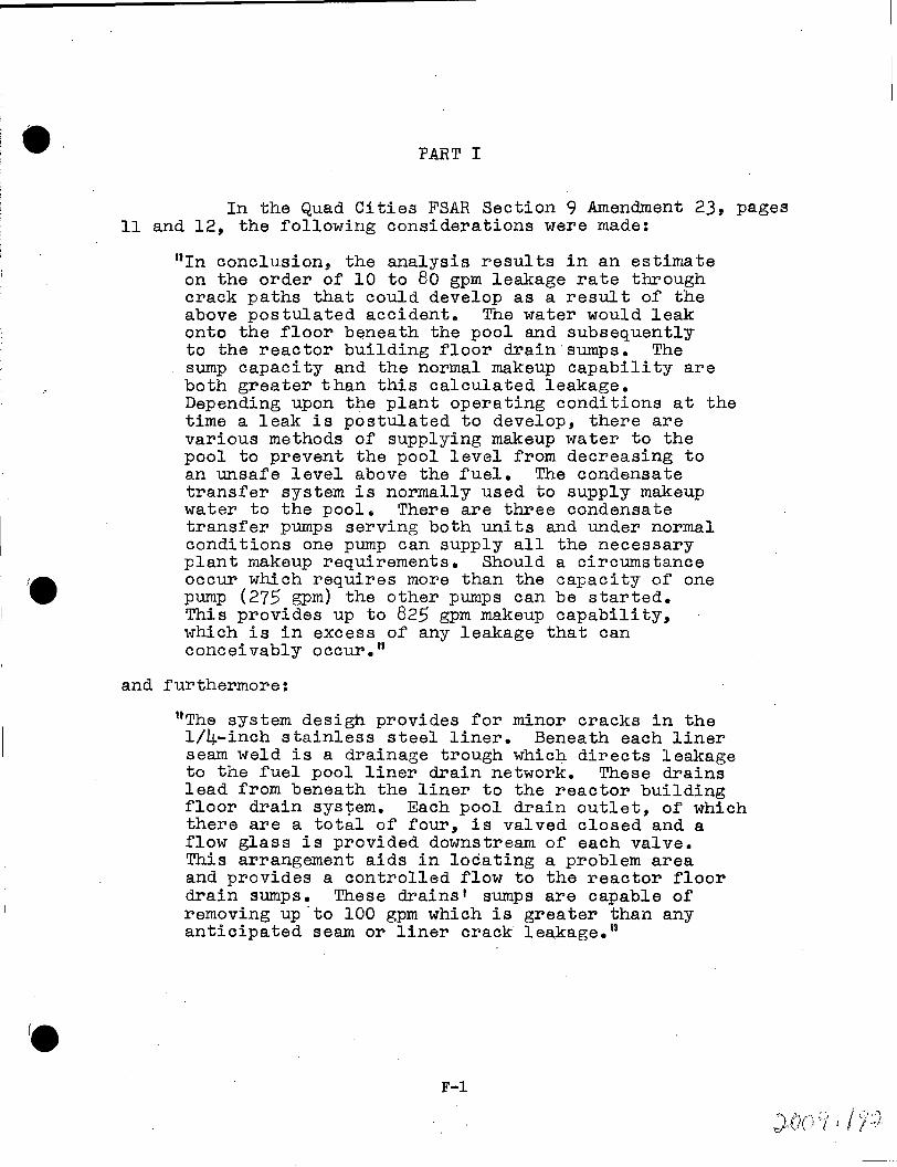
e. PART I
In the Quad Cities FSAR Section 9 Amendment 23, pages 11 and 12, the following considerations were made:
11In conclusion, the analysis results in an estimate on the order of 10 to 80 gpm leakage rate through crack paths that could develop as a result of the above postulated accident. The water would leak onto the floor beneath the pool and subsequently to the reactor building floor drain·sumps. The sump capacity and the normal makeup capability are both greater than this calculated leakage. Depending upon the plant operating conditions at the time a leak is postulated to develop, there are various methods of supplying makeup water to the pool to prevent the pool level from decreasing to an unsafe level above the fuel. The condensate transfer system is normally used to supply makeup water to the pool. There are three condensate transfer pumps serving both units and under normal conditions one pump can supply all the necessary plant makeup requirements. Should a circumstance occur which requires more than the capacity of one pump (275 gpm) the other pumps can be started. This provides up to 825 gpm makeup capability, which is in excess of any leakage that can conceivably occur."
and furthermore:
ttThe system desigh provides for minor cracks in the 1/4-inch stainless steel liner. Beneath each liner seam weld is a drainage trough which directs leakage to the fuel pool liner drain network. These drains lead from beneath the liner to the reactor building floor drain system. Each pool drain outlet, of which there are a total of four, is valved closed and a flow glass is provided downstream of each valve. This arrangement aids in loc.a ting a problem area and provides a controlled flow to the reactor floor drain sumps. These drains' sumps are capable of removing up.to 100 gpm which is greater than any anticipated seam or liner crack leakage."
F-1

- 2 -
Given the design similarities between Quad Cities and Dresden Stations, these comments are applicable to Dresden Unit 2. Dresden is more conservative, however, since there are two condensate transfer pumps per unit which are cross-tied. Hence four pumps are available instead of the three mentioned above.
In addition to the condensate transfer pumps, which are normally used for make-up, the fuel pool can be fed from the condensate system directly through a 6 11 diameter line off the header. This connection is made by manually opening valve #2-1904-5-~7.
In considering the significance.of a cask drop and the postulated loss of all fuel pool water the effects of this water on safe shutdown of the reactor were evaluated. It was concluded from this evaluation that the reactor can be safely shutdown and maintained in a safe condition. It was also determined that with certain temporary provisions to control the fuel pool water within the reactor building, all engineered safeguard system will be maintained in proper condition for operation.
Should a fracture of the fuel storage pool occur and the size is such that the flow exceeds the capacity of the 100 gpm floor drain sump pumps flooding will occur at floor elevations 545'-6", 517 1 -6 11 , and 476 1 -6° within the reactor.
At elevation 545 1 -6° the stairwells and the 20' x 19 1
equipment hatch will serve as large drains and prevent· a buildup of water. The significant equipment at the 545'-6 11
elevation is the 4 Kv switchgear (GR-23-1 and GR-24-1) and reactor instrument rack 2202-5. The switchgear is protected by a 4.;.inch high· curb at the f'loor and a watertight, sloping. roof with gutters with downspouts directing water outside the curb.
It is highly unlikely that any instruments on rack 2202-5 would be effected by falling water and are located above the floor sufficiently to preclude consideration of the effects of total submergence. In the event these instruments were assumed to fail the reactor could still be shutdown safely. Water will not enter the cable pan risers which are protected by 3 inch high curbs. No significant water will enter the Unit 3 reactor building through the interconnecting door at this elevation. ·
At elevation 517 1 -6 11 no significant effects will result if the water level can be restricted to below the 3-inch curbs enclosing the motor control centeri and the cable pan risers at this elevation. The water level can be restricted by removing the 4-foot square accesB covers to the torus area of the basement.
F-2
.4, ,,.;(\ <1 , I q ':. r;' •: .. · . 1 1 · J -·

- 3 -
At elevation 476 1 -6 11 the significant equipment is the ECCS pumps and motors located in the "corner rooms". Water can be prevented from entering these "corner rooms" by surrounding the stairwells at elevation 517 1-6 11 with sand bags.
Ultimately the approximately 400,000 gallons of water from the fuel pool would drain to the torus area of the reactor building basement. In this location it would have no adverse effect during the time required to dispose of the water.
F-3

PART II
The 753 spent fuel assemblies in the Dresden Unit 2 pool have a wide range of exposures:
509 assemblies 4063 MWD/ton (avg~) 4777 MWD/ton (max.)
186 assemblies 1625 MWD/ton (avg.)
29 assemblies 1286 MWD/ton (avg.)
29 assemblies 330 MWD/ton (avg.)
The average rated bundle power was 3.5 MWT and the average Unit 2 output in the last 2 months prior to discharge was 62% of rated power. For calculation purposes, 4063 MWD/ton was used.
The decay of this particular core of fuel is significantly advanced. Unit 2 was unloaded well over a year ago. The expected dose rate (in the event the water is drained completely from the pool) in the reactor building on the refueling floor (20 ft. from the spent fuel storage pool) is less than 0.2 R/hr.
The dose rate 2000 ft. from the spent fuel storage pool (at the plant boundary) is less than O.l mr/hr. Assuming that the core will be recovered with water within 30 calendar days, the maximum dose at the fence post will be less than 36 m.r due to the incident.
30 days x 24 hrs/day
720 hrs x O.l mr/hr
= 720 hrs
= 72 mr
(assuming an occupancy factor of 2)
72 mr/2 = ·36 mr
This maximum dose of 36 mr is well. within the requirements of 10CFR20 and lOCFRlOOo
F-4

P.AR'r III
The f'uel presently in the Dresden Unit 2 pool was removed from the reactor vessel some 16 months ago. As such, the decay power is now changing slowly and amounts to only 0.08 percent of the original. If an accident were to occur causing a complete water loss from the f'uel storage pool and leaving the f'uel rods exposed to open air, a natural question to introduce is: "Can natural or free convection provide the necessary heat transfer to compensate for the presence of decay power and thus maintain cladding temperatures below the perforation temperature limit?"*
The .temperature and geometry characteristics of this problem result in Grashof (Gr) number in excess of 109 for the most part. This free convection level as well as the presence of crossflow define a turbulent flow regime in the exposed bundles. Convective heat transfer coefficients (h) under those conditions may be.calculated using:
1/3
for a particulaIJ length L on an isolated fuel rod. K and Pr are the thermal conductivity and the Prandtl number respectively. Note that the above equation is not length dependent, thus the convection process is dependent only on the coolant properties at the mean temperature of the fuel rod and the ambient air.
At 100°F ambient air temperatures and conservatively assuming constant peak decay power over the full length of the fuel rods, the natural convection process will provide heat transfer coefficients of a sufficient magnitude to limit cladding temperatures to a safe level. Specifically, rods on the periphery of the storage racks will not greatly exceed 500°F. Although interior rods will have cladding temperatures greater than 500°F., the presence of a constant crossflow providing a continuous source of low temperature air should not allow temperatures to exceed 1000°F.
With cooling only by free convection in air, the fuel rods on the periphery of the storage racks will provide the majority of the radiation heat transfer to the concrete floor.. Since these rods would not reach cladding temperatures greater than 500°F., the radiation load impo·sed by a source temperature of this magnitude is low. The resulting free convection on the concrete would limit the floor temperature level to a value less than 200°F.
The temperature. levels listed above show the f'uel rods to have substantial margin from the perforation limit~ Further, since the perforation temperature limit itself is a conservative value, additional margin is inherent in this compurison. Concrete temperature levels are found to be such that no concern should exist about its structural integrity.
*The Perforation Temperature is 1500°F. See the c:;µad Cities FSAR 14.2.4.2.
F--5


