Halliburton Drill Bits and Services coring technology is the subject of the following U.S. patents:
4,930,587 5,169,183 5,209,310
5,351,765 5,460,230 5,501,285
6,116,358 6,145,604 6,158,534
6,164,389 6,341,656 6,394,196
6,644,424 7,021,404 7,117,958
7,320,373
CAL™
CD™
CleanCore™
CQLSM
CorientingSM
CT™
FCS™
Fibertube™
Glider™
HSB™
Latch-Les™
Low Invasion™
MITP™
PosiClose™
Sponge Coring™
TB™
TBT™
TD™
Trademarks of Halliburton:
DRILL BITS & SERVICES
HALLIBURTON
Corienting™ Services
2
Corienting services enables geologists to know the orientation and direction of the core prior to formation removal. The system provides a variety of 3-D models and sophisticated measurements of the reservoir. Corienting accurately relates the core to electronic measurements of a survey tool using gravitational and magnetic fields of the earth.
Corienting™ Services for Reliable 3-D Reservoir Modeling
3
Reliable Geology Modeling
Enables operators to visualize reservoir architecture to plan the most effective recovery of hydrocarbons.
Dip and Strike
Provide angles and directions of fractures necessary for effective development.
Three Scribed Grooves
Are knifed into the core. The principle scribe line is related to the magnetic or gravity high side of the survey tool.
Rose Diagrams
Are one of the means of presenting core re-orientation to geologists, describing the original azimuth of bedding planes, fractures and any other secondary feature of the formation.
180°
160°
120°
90°
60°
30°
N
HAL12452
HAL12401
HAL12402
HAL12437
4
The scribe shoes have unequal angles between each knife. One knife is identified as the principal reference knife. The upper half scribe shoe (right) is more suitable for
softer, unconsolidated formations, while the lower half scribe shoe is better for harder,
broken, or fractured formations. A complete
range of knife sizes ensures suitability for
particular formations.
Rugged, Reliable SystemThe Corienting system features robust, rugged designs to ensure reliability down hole. The electronic survey tool is protected from rotation, mud flow, and vibration. Scribe shoes allow coring in a broad range of formations, from soft and unconsolidated to hard and broken. The electronic survey tool is positively located so that unwanted rotation relative to the scribe line is eliminated.
Prior to coring, the system allows clearing of the inner barrel with flushing. When the circulating ball is dropped, it seals the top of the inner tube and diverts mud flow into
the annulus, protecting the survey tool while coring and avoiding washing of the core.
The safety joint isolates the inner tube and survey tool from rotation.
The survey tool is held within the non-magnetic core barrel, protected from rotation, mud flow, and vibration.
Stabilizers
Scribe Shoe
HAL1
2459
HAL1
2467
ElECTRoniC SuRvEy Tool
CoRE
MainSCRibinG
KnifE
The Electronic survey measurements are referenced with the primary line scribed into the core, which enables re-orientation. The electronic survey tool measures and records tool azimuth and inclination in relation to the earth’s magnetic and gravitational fields. H
AL1
2465
HA
L124
68
5
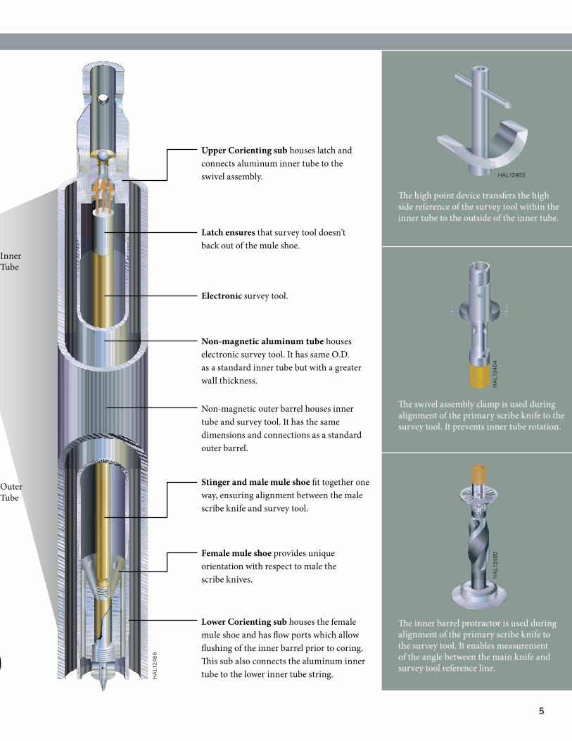
Inner Tube
Outer Tube
Upper Corienting sub houses latch and connects aluminum inner tube to the swivel assembly.
Latch ensures that survey tool doesn’t back out of the mule shoe.
Electronic survey tool.
Non-magnetic aluminum tube houses electronic survey tool. It has same O.D. as a standard inner tube but with a greater wall thickness.
Non-magnetic outer barrel houses inner tube and survey tool. It has the same dimensions and connections as a standard outer barrel.
Stinger and male mule shoe fit together one way, ensuring alignment between the male scribe knife and survey tool.
Female mule shoe provides unique orientation with respect to male the scribe knives.
Lower Corienting sub houses the female mule shoe and has flow ports which allow flushing of the inner barrel prior to coring. This sub also connects the aluminum inner tube to the lower inner tube string.H
AL1
2466
HAL12403
HAL1
2404
HAL1
2405
The high point device transfers the high side reference of the survey tool within the inner tube to the outside of the inner tube.
The swivel assembly clamp is used during alignment of the primary scribe knife to the survey tool. It prevents inner tube rotation.
The inner barrel protractor is used during alignment of the primary scribe knife to the survey tool. It enables measurement of the angle between the main knife and survey tool reference line.
HA
L124
65
6
2468101214161820 2 4 6 8 10 12 14 16 18 20
0
0
5
5
10
10
2
4
6
8
10
12
14
16
18
20
2
4
6
8
10
12
14
16
18
20Circle unit in %
0
30
60
90
0°
10°
20°
30°
40°
50°
60°
70°80°
90°
120
150
180
210
240
270
300
330
128 data
Number
Dips
Core Gamma logger
The portable Core Gamma Logger helps determine plug taking points. It provides gamma ray logs which primarily help to correlate cored sections with anticipated lithologies.
on Site Re-constitution and analysis
On site re-constitution and analysis is provided by a computer aided Goniometer and speciality software.
HAL12
408
Core Gamma Logger
Plug Taker
HAL25074HAL25077
Effective Surface HandlingPlug taking can provide data on the direction of permeability, correlated with corienting technology. Plug taking also allows immediate evaluation at the surface to avoid further diffusion of invasion, reducing the time between acquisition and first analysis. Plugs can also be transported to the laboratory faster than whole cores.
7
Corienting™ System Technical Specifications
SySTEM (baRREl X CoRE SiZE)
4-3/4" x 2-5/8" 6-3/4" x 4" 8" x 5-1/4"
iMPERial METRiC iMPERial METRiC iMPERial METRiC
Hole Size Compatibility 6 to 7 in. 152-178 mm 8 to 9 in. 203 to 229 mm 9 to 12-1/4 in. 229 to 311 mm