1 ANDRILL Coulman High (CH) Project Operational scoping document TR Falconer & AR Pyne Science Drilling Office, Antarctic Research Centre Victoria University of Wellington Final Version: March 2009 1 Executive Summary This document is designed to scope the major requirements for ANDRILL operations at the proposed Coulman High drill sites, which are located beneath the Ross Ice Shelf (RIS) about 55 km east of Cape Crozier (Ross Island). Extensive experience gained during the “remote” Cape Roberts Project operations (Fig. 1) and more recent ANDRILL McMurdo Ice Shelf (MIS) (2006/07) and camp supported Southern McMurdo Sound (2007) Projects is used to develop the most viable operations scenario. This scenario represents a ‘best operational model’ based on what we currently understand regarding the scientific objectives of the CH Project and nature of the drill sites (location and environmental parameters). We acknowledge that alternative approaches exist and that some of these approaches may prove desirable as the Project evolves. On review of this document if alternate approaches are considered worthy of further discussion we recommend that an operations development team be established as soon as possible to explore alternative approaches as required. The Coulman High targets will be drilled from a 300 m thick ice shelf moving at ~750 metres per year. Progressive development of current ANDRILL drilling technology will be required to enable operation through an ice shelf environment that is thicker and moving faster than the ice shelf site used during the MIS Project. A review of the required drilling technology has been started. Existing camp support operations will also require further development to operate on thicker ice and to allow storage (including winterisation) of the camp and drill site equipment for 3-4 seasons. Traverse capability for all drill site and camp equipment is also a significant issue and will need to be addressed if timely site access (set-up) and ongoing operations (resupply) are to be achieved. The primary recommendations and proposed operational approaches outlined in this document include: • Research, development, and testing of new technology to enhance existing ANDRILL equipment is required to enable drilling from the fast moving Ross Ice Shelf above the Coulman High drill sites
Transcript
1
ANDRILL Coulman High (CH) Project Operational scoping document TR Falconer & AR Pyne Science Drilling Office, Antarctic Research Centre Victoria University of Wellington Final Version: March 2009 1 Executive Summary This document is designed to scope the major requirements for ANDRILL operations at the proposed Coulman High drill sites, which are located beneath the Ross Ice Shelf (RIS) about 55 km east of Cape Crozier (Ross Island). Extensive experience gained during the “remote” Cape Roberts Project operations (Fig. 1) and more recent ANDRILL McMurdo Ice Shelf (MIS) (2006/07) and camp supported Southern McMurdo Sound (2007) Projects is used to develop the most viable operations scenario. This scenario represents a ‘best operational model’ based on what we currently understand regarding the scientific objectives of the CH Project and nature of the drill sites (location and environmental parameters). We acknowledge that alternative approaches exist and that some of these approaches may prove desirable as the Project evolves. On review of this document if alternate approaches are considered worthy of further discussion we recommend that an operations development team be established as soon as possible to explore alternative approaches as required. The Coulman High targets will be drilled from a 300 m thick ice shelf moving at ~750 metres per year. Progressive development of current ANDRILL drilling technology will be required to enable operation through an ice shelf environment that is thicker and moving faster than the ice shelf site used during the MIS Project. A review of the required drilling technology has been started. Existing camp support operations will also require further development to operate on thicker ice and to allow storage (including winterisation) of the camp and drill site equipment for 3-4 seasons. Traverse capability for all drill site and camp equipment is also a significant issue and will need to be addressed if timely site access (set-up) and ongoing operations (resupply) are to be achieved. The primary recommendations and proposed operational approaches outlined in this document include: • Research, development, and testing of new technology to enhance
existing ANDRILL equipment is required to enable drilling from the fast moving Ross Ice Shelf above the Coulman High drill sites
• Primary mobilisation and support for Coulman High drilling operations should be undertaken via surface vehicle traverse from the McMurdo Station - Scott Base logistics hub. Existing USAP and Ant NZ logistical support (including ship cargo and light aircraft) will be needed but significant over-ice traverse resources (e.g. Case 535, Challengers and other heavy movers) will be required. We are proposing that two Case 535 Quadtrac vehicles be purchased and supplemented by support form McMurdo Fleet Operations.
• A remote self supporting camp in the vicinity of the Coulman High drill
sites should be established to facilitate efficient and effective drilling operations.
This final version was completed in March 2009. It incorporates minor corrections and a reduction of detail in the financial section, as full details were not available. Some recent discussion between parties indicates that the timeline presented may not be realistic. However the sequence of tasks remains valid.
3.1 Scope of this report ...........................................................................7 3.2 Scientific rationale for drilling .............................................................7 3.3 Site parameters .................................................................................9 3.4 Current state of existing ANDRILL assets & experienced personnel 11
3.4.1 Ownership of equipment...........................................................11 3.4.2 Condition of equipment.............................................................11 3.4.3 Location of equipment ..............................................................11 3.4.4 Pool of experienced personnel .................................................11
3.5 Remote Site Operations - What should be supported in the Field? .12 4 Proposed Drilling Strategies ...................................................................12
4.1 ANDRILL Engineering Task Force background...............................12 4.2 Strategy 1 - Fast Drilling ..................................................................13 4.3 Strategy 2 - Re-entry .......................................................................14 4.4 The critical role of sea riser modelling .............................................15
5 Proposed On-Ice Operational Strategy...................................................16 5.1 Site surveys .....................................................................................16
5.1.1 Overview ..................................................................................16 5.1.2 Site surveys – science requirements ........................................17 5.1.3 Site surveys – drilling operations requirements ........................17
5.4.2.1 Shift Drill Crew...................................................................22 5.4.2.2 Engineering support ..........................................................22 5.4.2.3 Hot Water Drill operations .................................................22 5.4.2.4 ROV operations.................................................................23
5.4.3 Roles of personnel at the CH drill site(s), camp, McMurdo Station and Scott Base ...........................................................................23
5.5 Drill Site Science .............................................................................23 5.5.1 Drill site laboratory science operations .....................................23 5.5.2 Down hole logging....................................................................24
3
5.5.3 Drill site infrastructure...............................................................24 5.5.4 Science personnel at the drill site .............................................25
5.7 Fuel requirements............................................................................27 5.8 Traverse development .....................................................................28
5.8.1 Background – traverse capability and route development ........28 5.8.1.1 Route.................................................................................28 5.8.1.2 Traversing scenario ...........................................................29 5.8.1.3 Tow unit requirements .......................................................29
5.9 Drill season traverse operation ........................................................29 5.10 Air support .......................................................................................30
5.10.1 Personnel transport coordination..............................................30 5.10.2 Transport of science equipment & supplies..............................30 5.10.3 Core transport coordination ......................................................30 5.10.4 Runway maintenance and snow clearing .................................31
5.12.1 Engineering support .................................................................31 5.12.2 Vehicle maintenance ................................................................31
6 Development and purchase requirements ..............................................32 6.1 Drill system development – general.................................................32
6.1.1 Rig/platform/power pack...........................................................32 6.1.2 Cellar and catwalk ....................................................................32 6.1.3 Mud supplies, mud system and pumps ....................................33
6.2 Hot Water Drill – Mobilisation ..........................................................33 6.2.1 Drill site.....................................................................................33
6.2.2 Camp........................................................................................34 6.2.3 Mobilisation and operation of the current ANDRILL HWD........34
6.2.3.1 Existing Components ........................................................34 6.2.3.2 New Mobilisation and remote operations components ......34
6.4.1 Drill site laboratory modifications..............................................35 6.4.2 Down hole logging support requirements .................................35 6.4.3 ROV operations container & sledge .........................................36
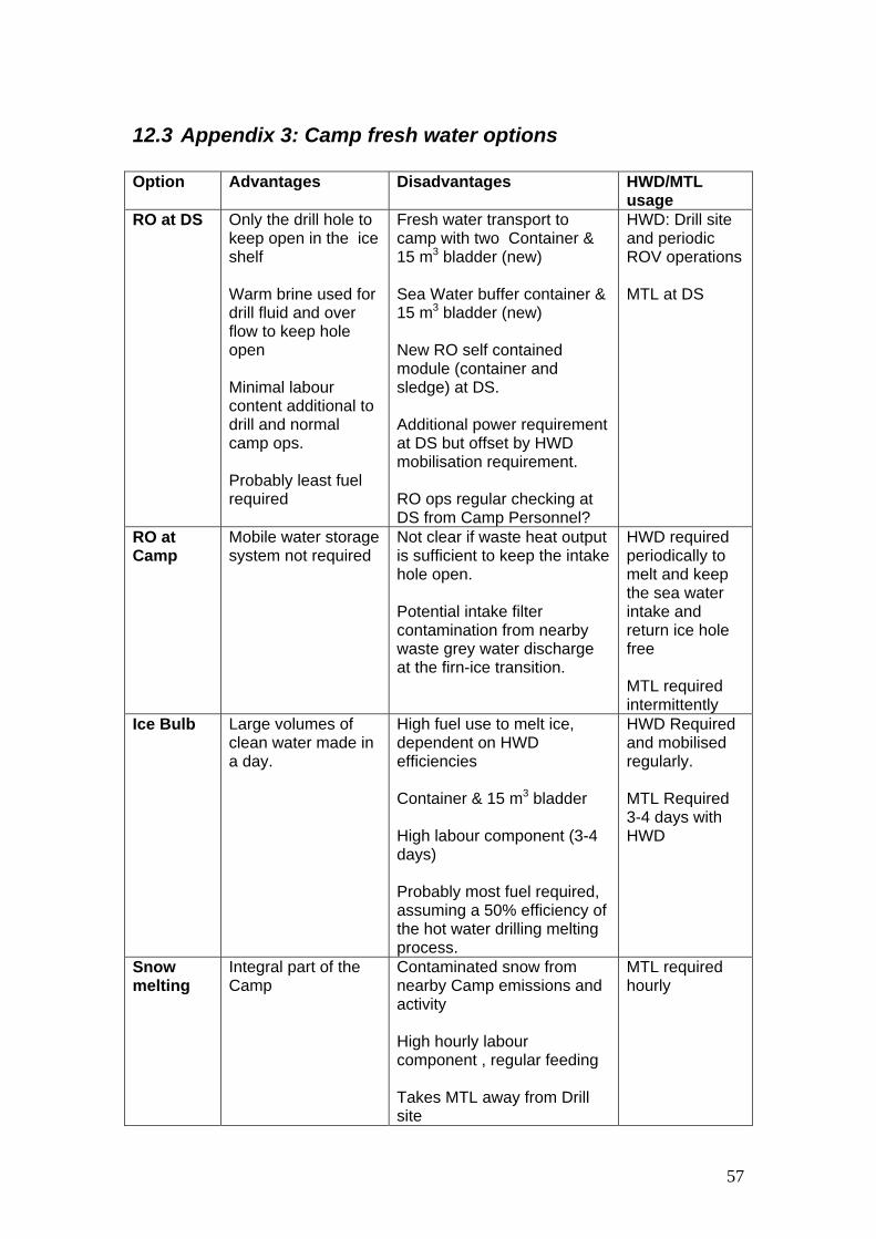
6.5 Camp development .........................................................................36 6.5.1 Sleeping facilities......................................................................36 6.5.2 Fresh water supply ...................................................................36
6.5.2.1 Ice shelf considerations .....................................................37 6.5.3 Other camp facilities .................................................................38
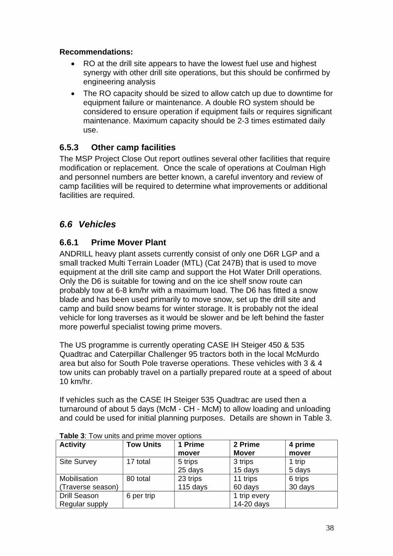
6.6 Vehicles ...........................................................................................38 6.6.1 Prime Mover Plant ....................................................................38 6.6.2 Timing and currently available traverse resources ...................39 6.6.3 Other heavy plant requirements ...............................................39
4
6.6.4 Other vehicles ..........................................................................40 6.6.4.1 Hagglunds .........................................................................40 6.6.4.2 Skidoos .............................................................................40
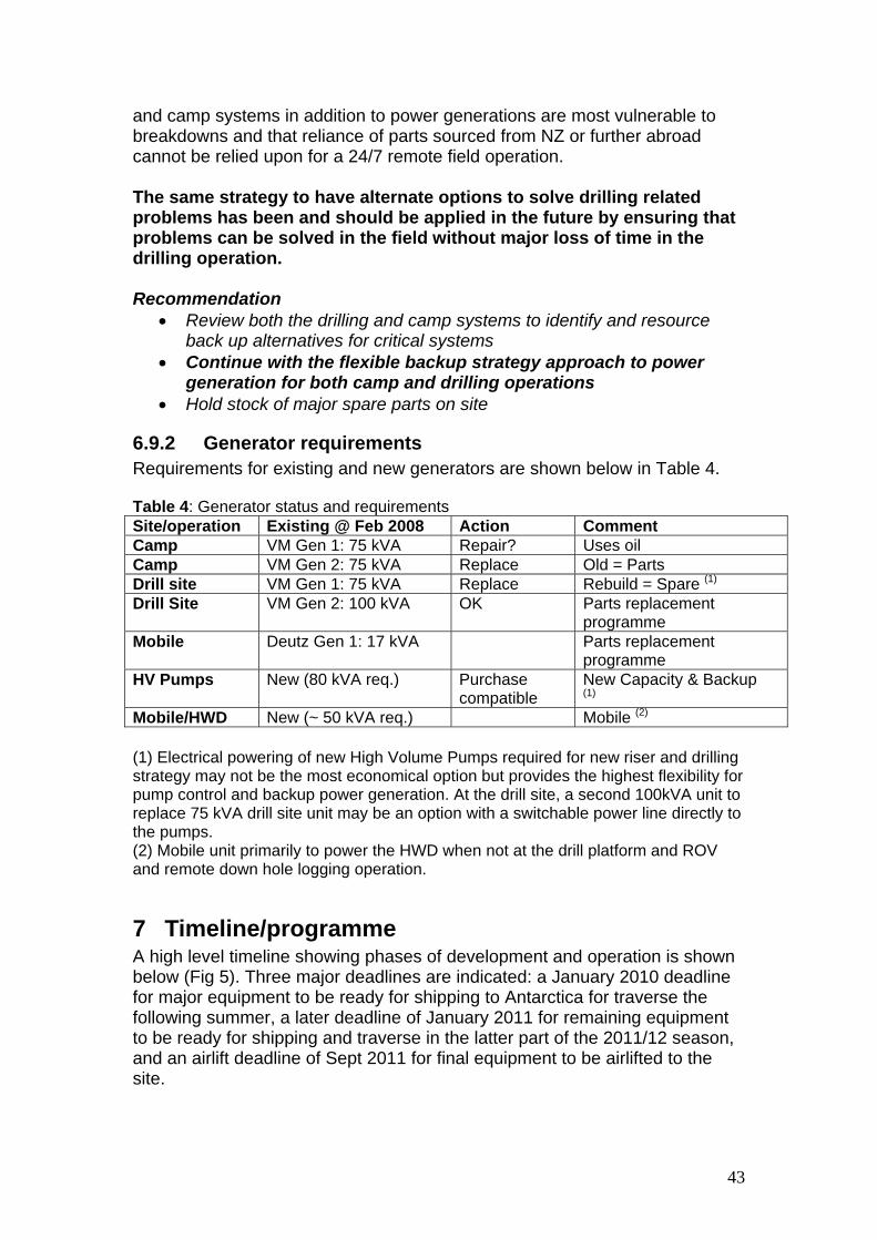
Recommendations: .............................................................................41 6.8 Fuel tanks and fuel sledges .............................................................41 6.9 Drill Site and Camp Power Generation............................................42
6.9.1 Power generation .....................................................................42 6.9.2 Generator requirements ...........................................................43
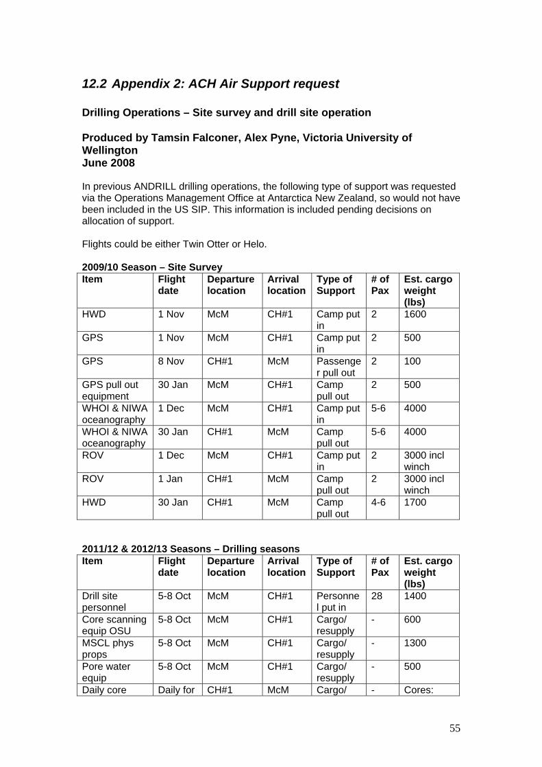
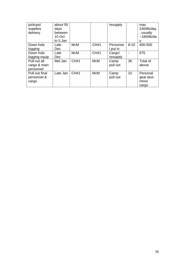
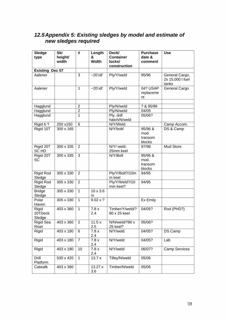
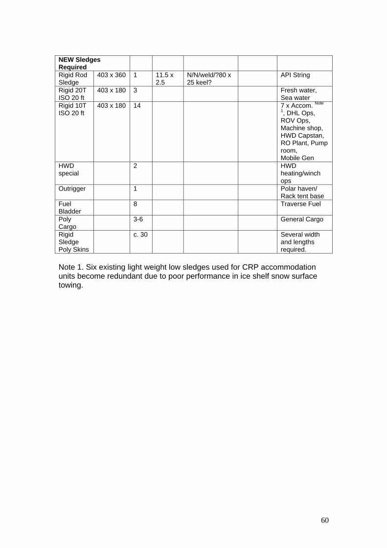
12.1 Appendix 1: Fuel use estimates (2008) ...........................................54 12.2 Appendix 2: ACH Air Support request .............................................55 12.3 Appendix 3: Camp fresh water options............................................57 12.4 Appendix 4: Fresh water making options: First estimate of Fuel Use 58 12.5 Appendix 5: Existing sledges by model and estimate of new sledges required ......................................................................................................59
2 Acknowledgements This document draws heavily from the ANDRILL McMurdo Sound Portfolio Close-Out Report produced by Antarctica New Zealand for the ANDRILL Operations Management Group (AOMG) which was compiled by Iain Miller with assistance from Johno Leitch and Jim Cowie (Miller, 2008). We wish to acknowledge the additional intellectual input of Johno Leitch, Jeremy Ridgen, Richard Levy and Tim Naish into the compilation of this report. This report has been completed by Victoria University of Wellington’s Antarctic Research Centre Science Drilling Office (SDO) funded by Antarctica New Zealand and the ANDRILL Steering Committee (ASC).
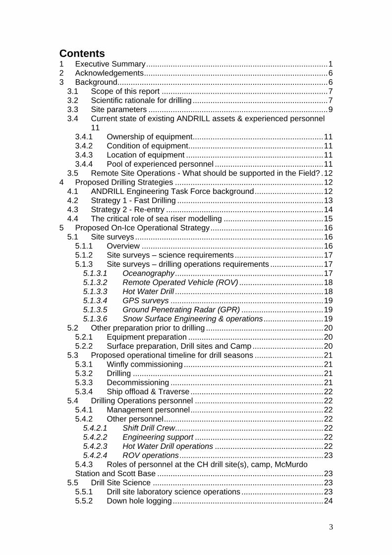
3 Background Since 1970 several major geological drilling projects (e.g. DVDP, MSSTS, CIROS, CRP, ANDRILL MIS and SMS) have been successfully operated in the McMurdo Sound region, Antarctica with support from logistics hubs at McMurdo Station and Scott Base (Fig. 1). These drilling operations have primarily been carried out during the summer field season and, since 1975 have been located on a “time limited platform” such as sea ice or ice shelf. To achieve each project’s drilling goals, set up for each operational season typically started in late August (Winfly) and continued from early October with a drilling operation that ran 24-hours per day, seven days per week. Continuous drilling allows deep targets to be reached within the time-constrained operational window. In addition, a continuous in-hole drilling operation increases the ability to control the hole which is critical when drilling in often unstable marine sedimentary sequences that are commonly the geological targets. A 24 hour drilling operation will be required at the Coulman High sites. From the DVDP onwards, projects have utilized Winfly airlift (August) to provide sufficient time for drill site set up prior to drilling operations beginning in early main body (early October). If Winfly capability is not available in future, drill season operations will be severely constrained and deep drilling targets may become impractical. A continuous drilling operation also requires seamless support from drill site staff. All past operations (except the MIS Project, which was located 12 km from Scott Base) established a remote camp to support the drill site shift personnel and ensure that drilling and science operations progressed as smoothly as possible. In 2007, the SMS Project was operated from a camp located 35 km from McMurdo Station/Scott Base and between 1997 and 1999 the Cape Roberts Project operated from a self supporting camp located 130 km from McMurdo Station/Scott Base. These highly successful projects highlight the required operational infrastructure and prove that a self-supporting camp and drill site model is the most efficient and effective method to ensure successful drilling outcomes.
6
This model currently represents the best way to conduct a complex geological drilling project in remote and challenging “ice-platform-based” Antarctic environments.
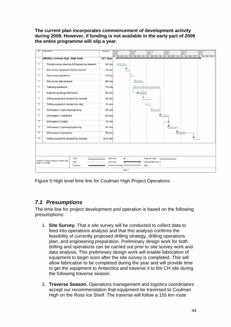
Figure 1: Location map showing the north western Ross Ice Shelf, Coulman High sites, the local South Pole Route and McMurdo Sound
3.1 Scope of this report The document is expected to provide sufficient detail and operational justification to: • Provide the foundation to develop a Project Plan for the ANDRILL
Coulman High (CH) Project • Provide timelines for project development and operations • Provide the rationale to engage a Project Operator
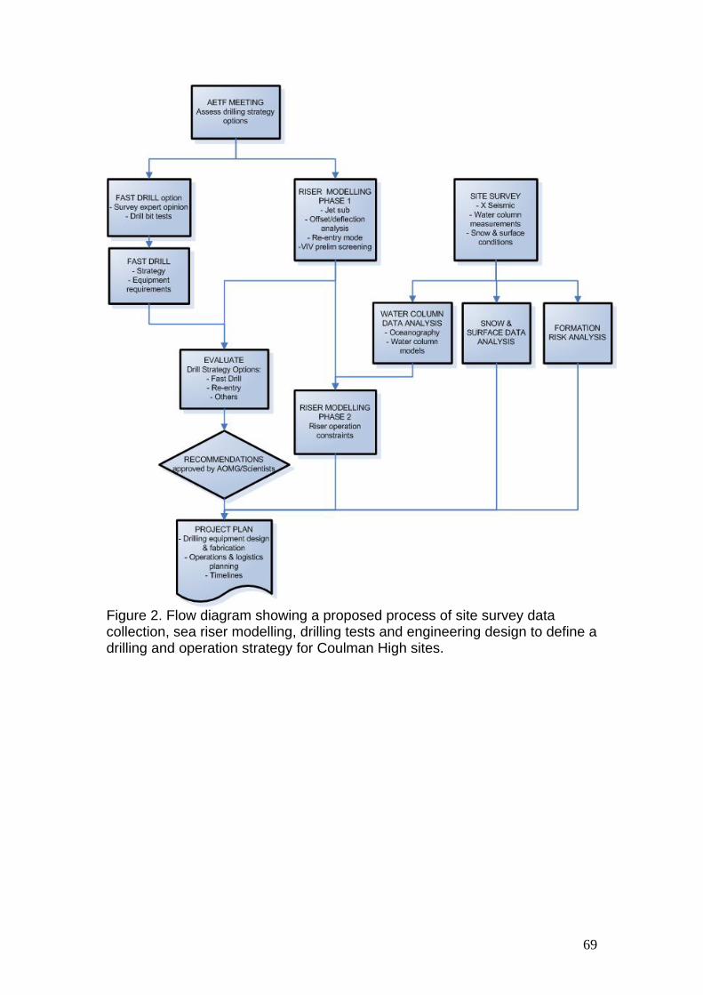
3.2 Scientific rationale for drilling The scientific rationale for drilling at CH is outlined in several documents including the ANDRILL Coulman High Scientific Prospectus and various science proposals submitted to National Funding agencies. A basic summary of the scientific objectives is included below: ANDRILL proposes to drill two sites on CH (Fig. 1 and 2), moving eastward and outside the well-understood Victoria Land Basin (VLB) to target a
7
Cretaceous(?)-Paleogene to middle Miocene section in order to address fundamental questions of global climate evolution and regional tectonics. This will enable us to determine fundamental shifts as well as transient excursions in the Antarctic cryosphere that impacted global ocean and climate reorganization. We will use the excellent chronostratigraphic framework for the western Ross Sea (RS) and Southern Ocean to provide needed stratigraphic constraint on an extensive network of seismic data across the rest of the RS. CH drilling will provide a high-resolution record of the glacial and tectonic evolution of West Antarctica (WANT), providing critical geological constraints for Cenozoic icesheet and climate models. Four of ANDRILL’s programmatic themes will be addressed by an integrated approach involving site surveys, core recovery and analysis, regional interpretation, and numerical modelling: (1) history of Antarctic climate and ice sheets; (2) Antarctica’s role in Earth’s ocean-ice-climate system; (3) evolution of polar biota; and (4) Antarctic tectonics. The international CH Project will acquire and study high-quality continuous sediment cores from two (>1200 m-deep) drill holes. CH Project results will provide insight on: (1) development of the Antarctic cryosphere with a focus on the influences of WANT; (2) magnitude and frequency of West Antarctic cryosphere changes on millennial timescales during times of high atmospheric CO2; (3) influence of West Antarctic ice sheets (WAIS) on Paleogene to Miocene climate, thermohaline circulation, and eustasy; and (4) timing of Antarctic tectonic episodes leading to an understanding of the role of Antarctic plate motion in the global plate circuit, and the development of sedimentary basins. Note that the target depth of 1200 mbsf per hole is based on probable operational constraints, which were based on drilling rates achieved during the MIS and SMS Projects. The 1200 mbsf target depths may change due to re-evaluation and modification of scientific objectives and/or operational constraints; particularly after site survey analyses have been completed. The primary drilling requirement is to obtain continuous high-quality core to target depth below the sea floor. At this stage in the project planning process it seems likely that the fast moving ice shelf will significantly impact available on-site drilling time and will likely restrict down hole logging operations. Down hole data is likely to be of interest to many science team members and may be considered a critical part of science operations. If a successful coring and logging programme is to be achieved development or acquisition of new downhole equipment and/or different operational approaches will be required. New equipment may include multi-tools and operational changes such as deployment through the ice shelf and water column into the initial hole once a new hole is being drilled. The application of these ‘new’ approaches will be dependent on outcomes of equipment and operations investigations described in this document.
8
3.3 Site parameters Parameters of Coulman High sites:
• Ice shelf thickness ~250m (design capability up to 300m) • Freeboard (elevation above sea level) ~ 40m • Ice shelf draft (depth below sea level) ~ 210m • Horizontal movement ~ 750m per year (2.05 m/day) • Water column (below ice) ~ 560m • Sedimentary drilling targets: 1000-1200 m below sea floor
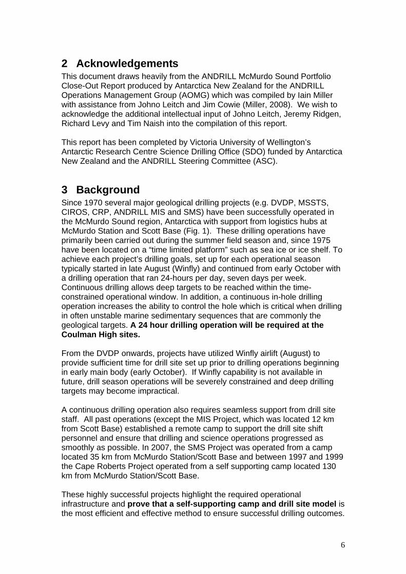
The first priority CH drill site is located at 77.46596oS 171.58169oE and the second at 77.46185oS 171.23015oE (Fig 2). The Coulman High sites are approximately 125 km north-east of McMurdo Station. These sites were identified using marine seismic data collected when the C-19 iceberg broke off the front of the ice shelf in 2002 allowing the RV Nathaniel B Palmer to access the area in 2003/04. The ice shelf has subsequently advanced over the proposed drill sites providing a platform for drilling. It is anticipated that these sites will be approx 6 km from the ice shelf edge by the anticipated start of drilling in October 20111. The sites are ~155 km from McMurdo Station/Scott Base by surface route. The route would initially follow the South Pole route through the shear zone east of White and Ross Islands then to the Coulman High area (Fig. 1). Surface traverse of equipment from McMurdo Station to the Coulman High sites is considered the most viable option. Due to the relative proximity of the sites to McMurdo Station and the fact that the height of the Ross Ice Shelf (RIS) barrier is ~ 40 m, direct ship transport and offload of equipment at the ice shelf edge near the CH sites is not considered a practical alternative.
1 This is based on the ice shelf edge reaching the drill site in Oct 2003, and a movement rate of 750 metres/year.
9
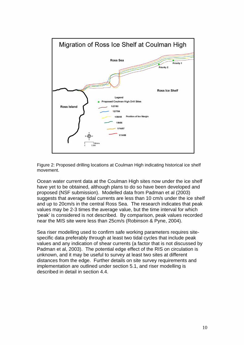
Figure 2: Proposed drilling locations at Coulman High indicating historical ice shelf movement. Ocean water current data at the Coulman High sites now under the ice shelf have yet to be obtained, although plans to do so have been developed and proposed (NSF submission). Modelled data from Padman et al (2003) suggests that average tidal currents are less than 10 cm/s under the ice shelf and up to 20cm/s in the central Ross Sea. The research indicates that peak values may be 2-3 times the average value, but the time interval for which ‘peak’ is considered is not described. By comparison, peak values recorded near the MIS site were less than 25cm/s (Robinson & Pyne, 2004). Sea riser modelling used to confirm safe working parameters requires site-specific data preferably through at least two tidal cycles that include peak values and any indication of shear currents (a factor that is not discussed by Padman et al, 2003). The potential edge effect of the RIS on circulation is unknown, and it may be useful to survey at least two sites at different distances from the edge. Further details on site survey requirements and implementation are outlined under section 5.1, and riser modelling is described in detail in section 4.4.
10
3.4 Current state of existing ANDRILL assets & experienced personnel
3.4.1 Ownership of equipment The current ANDRILL equipment developed for use in the initial McMurdo Sound Portfolio (MSP) is owned by the AOMG on behalf on the participating countries (USA, NZ, Germany and Italy), with the exception of the Drill Rig which is owned by a US University Consortium (University of Nebraska-Lincoln and Northern Illinois University). All equipment is currently under the management of Antarctica New Zealand as Project Operator until a new project structure is established or it becomes clear that no new project will occur 2. Antarctica New Zealand has been delegated responsibility for managing appropriate maintenance and storage, and issuing any equipment that is borrowed.
3.4.2 Condition of equipment The current condition of ANDRILL equipment has been outlined in detail in the Project Close Out Report, together with the plan for maintenance and storage (Miller, 2008). The report notes that some items will require remedial work or modification before they are used in future projects, but this evaluation has not been completed as the exact equipment requirements for future work had not been defined at the completion of MSP. Requirements for repair, maintenance and replacement are outlined in section 6.
3.4.3 Location of equipment The equipment is currently stored in three locations – near Pegasus Runway, McMurdo Ice Shelf, in Long Term Cold Storage at Scott Base, and at Antarctica New Zealand in Christchurch, New Zealand. The inventory is outlined in the Project Close Out Report. The majority of items that require significant work are stored in Christchurch to allow easy access once the work programme has been confirmed.
3.4.4 Pool of experienced personnel Reports from both the Cape Roberts Project (Cowie, 2002) and the ANDRILL MSP (Pyne, 2008) emphasise that experienced personnel are critical to the planning, management and success of Antarctic drilling operations. Given the time lag between drilling portfolios and the current demand in the minerals industry, re-attracting experienced personnel may be a challenge. The importance of experienced personnel is not restricted to the drill crew, but is also critical for engineering support and management/operations support. This needs to be figured into long-term planning and funding for the project.
2 The exact mechanism for defining the start point of a new project was discussed at AOMG in July 2008. Refer to the minutes of that meeting.
11
3.5 Remote Site Operations - What should be supported in the Field?
The primary requirement is to support a remote drilling effort that utilizes a continuous 24-hour operation (split into two 12 hour shifts) during the austral spring and summer period. In past projects the requirements of the drilling operation have been the fundamental driver for the way in which the field operation has been organised and supported. Drill site science operations are driven by the need to acquire ephemeral properties before the core changes (“degrades”) due to exposure at the Earth’s surface, handling, and transport. During recent ANDRILL operations whole core was transported back to McMurdo Station on a 1-2 day frequency. This differs from the CRP where more substantial infrastructure was required at the drill site to allow the core to be split and characterised prior to transport off-site. In addition to core-based science, site specific science can be undertaken in the bore hole such as downhole logging and hydrofracture experiments. Further details of drill site science are outlined in Section 5.5 below. To summarize: A 12-hour shift-structured operation is required at the CH sites to ensure that drilling and science operations can be maintained around the clock so that science targets can be met. A relatively self-sufficient remote camp and associated drill site infrastructure is required to support such an operation.
4 Proposed Drilling Strategies
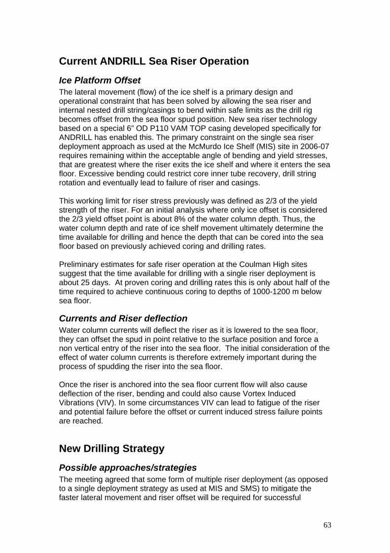
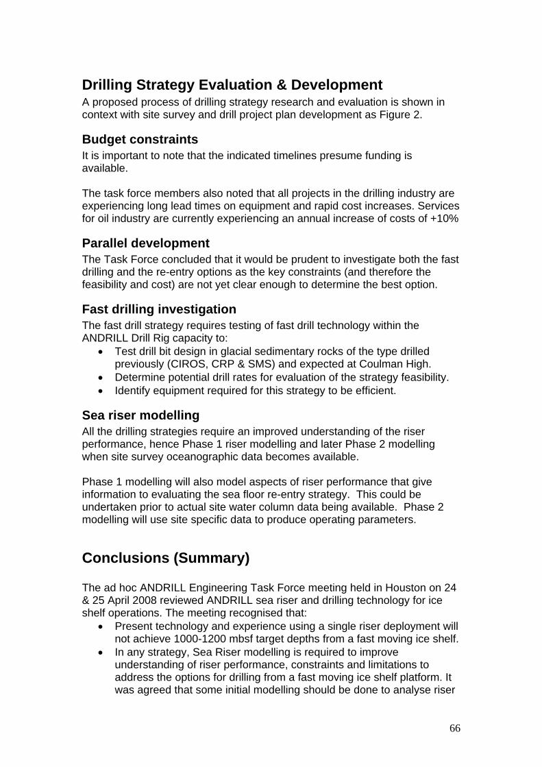
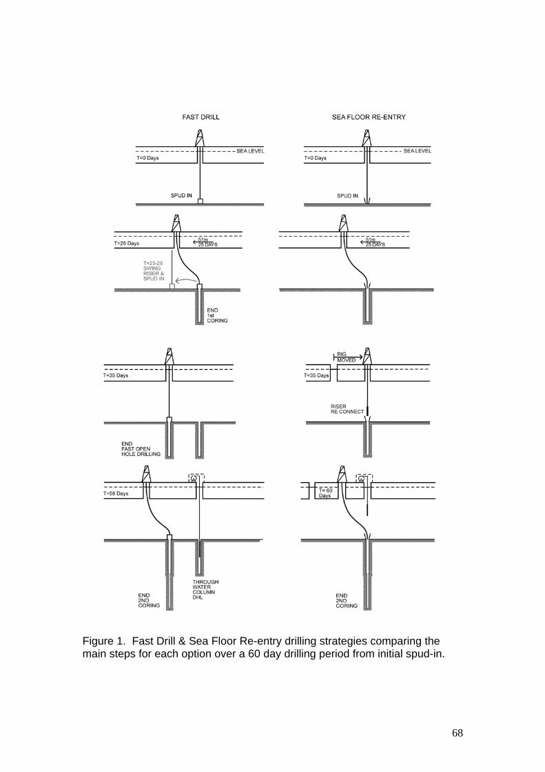
4.1 ANDRILL Engineering Task Force background An ad hoc meeting of an ANDRILL Engineering Task Force (AETF) was held in Houston, Texas in April 2008. The goal of this meeting was to discuss possible approaches to drilling from a fast moving ice shelf (see Annex 13.1). The CH sites were used as a case study but it was agreed that the design approach should consider fast moving ice shelves as a generic problem as future ANDRILL sites may also be situated beneath fast moving ice shelves. Meeting participants agreed that some form of multiple riser deployment to mitigate fast lateral movement and riser offset will be required for successful operation from fast moving ice shelves (as opposed to the single deployment strategy used during the MIS and SMS Projects). Three types of multiple deployment strategy were discussed and include: Fast drilling, re-entry, and ice shelf slotting. After preliminary calculation of melting rates and fuel usage, the ice shelf slotting option was abandoned. The two remaining options are considered viable but require further investigation to determine their relative merits and costs.
12
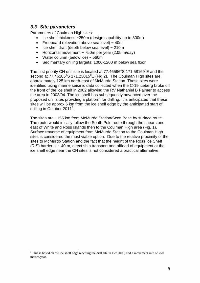
4.2 Strategy 1 - Fast Drilling The Fast Drilling strategy (Fig. 3) involves drilling multiple adjacent holes into the sea floor to obtain a composite record of cored strata to a target depth of 1000-1200m below sea floor. This strategy requires the capability to both core and drill (quickly) without coring. An initial hole would be cored to a given depth at which point the drill string and riser would be pulled from the sea-floor allowing the ‘bend’ in the riser to straighten. A new offset hole would commence using a fast drilling approach (i.e. drilling without coring) until the original hole depth was reached (allowing reasonable overlap). Coring would then commence at this level and the two holes would be combined to create a composite record. This approach would continue until the desired depth was attained (or operational constraints prohibited continued drilling). This strategy requires development of fast open hole drilling capability for the ANDRILL drill system in addition to maintaining or improving current coring practice. With this Fast Drilling capability only a single drill site setup on the ice platform is required and riser offset is mitigated by drilling multiple holes into the sea floor. Note that a downhole logging programme deployed via the water column could commence in the original hole while drilling/coring of the new offset hole continues (Fig. 3). Key advantages of the fast drilling strategy are that it largely uses proven concepts and the drill system does not need to be moved during drilling. Key limitations identified at present focus on the fact that realistic open hole drilling rates are currently unknown and required rates may not be possible. New drill bit research, development, and testing are required to evaluate this strategy and determine what drilling/coring depths are realistic. Further investigation for this option will include:
- Work with drill bit manufacturers to develop hardware and test techniques that will optimise fast open-hole drilling, in order to identify possible drilling rates
- Analysis and development of an open hole drilling fluids programme - Exploring options to deploy down hole logging tools through the water
column and into sea floor casing
13
Figure 3: Two potential drilling strategies for fast-moving ice shelves
4.3 Strategy 2 - Re-entry The re-entry strategy involves making a single drill hole in the sea floor and mitigating ice platform offset by moving the drill system on the ice shelf surface (Fig. 3). The most favoured variation of this type of strategy is the sea floor re-entry approach, where a sea floor re-entry assembly is established during the initial spud in of the riser. The re-entry assembly allows
14
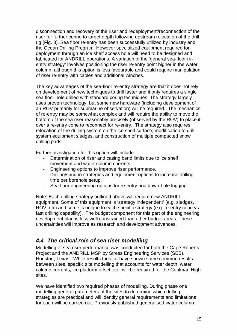
disconnection and recovery of the riser and redeployment/reconnection of the riser for further coring to target depth following upstream relocation of the drill rig (Fig. 3). Sea floor re-entry has been successfully utilized by industry and the Ocean Drilling Program. However specialized equipment required for deployment through an ice shelf access hole will need to be designed and fabricated for ANDRILL operations. A variation of the ‘general sea-floor re-entry strategy’ involves positioning the riser re-entry point higher in the water column, although this option is less favourable and could require manipulation of riser re-entry with cables and additional winches. The key advantages of the sea-floor re-entry strategy are that it does not rely on development of new techniques to drill faster and it only requires a single sea floor hole drilled with standard coring techniques. The strategy largely uses proven technology, but some new hardware (including development of an ROV primarily for submarine observation) will be required. The mechanics of re-entry may be somewhat complex and will require the ability to move the bottom of the sea riser reasonably precisely (observed by the ROV) to place it over a re-entry cone to reconnect for re-entry. The strategy also requires relocation of the drilling system on the ice shelf surface, modification to drill system equipment sledges, and construction of multiple compacted snow drilling pads. Further investigation for this option will include:
- Determination of riser and casing bend limits due to ice shelf movement and water column currents.
- Engineering options to improve riser performance. - Drilling/spud-in strategies and equipment options to increase drilling
time per borehole setup. - Sea floor engineering options for re-entry and down-hole logging.
Note: Each drilling strategy outlined above will require new ANDRILL equipment. Some of this equipment is ‘strategy independent’ (e.g. sledges, ROV, etc) and some is unique to each specific strategy (e.g. re-entry cone vs. fast drilling capability). The budget component for this part of the engineering development plan is less well constrained than other budget areas. These uncertainties will improve as research and development advances.
4.4 The critical role of sea riser modelling Modelling of sea riser performance was conducted for both the Cape Roberts Project and the ANDRILL MSP by Stress Engineering Services (SES), Houston, Texas. While results thus far have shown some common results between sites, specific site modelling that accounts for water depth, water column currents, ice platform offset etc., will be required for the Coulman High sites. We have identified two required phases of modelling. During phase one modelling general parameters of the sites to determine which drilling strategies are practical and will identify general requirements and limitations for each will be carried out. Previously published generalised water column
15
data (current velocity) can be used during this phase. Modelling results will contribute to the decision-making process to determine which drilling strategy to adopt and define some of the major engineering requirements. During phase two we will use water column measurements collected from CH site survey experiments to model specific operating parameters for each site. Both drilling strategies (described in 4.2 & 4.3) rely on drilling in a sea riser and casings that progressively bend within the water column as movement of the ice shelf platform accumulates with time. The limit to safe bending of riser and drill strings will determine how long (time) drilling can occur. This limit is dependent on factors that are specific to each drill hole setup (e.g. water column depth and rate of ice shelf offset). In addition, water column currents affect the riser. Analysis of how these effects are imposed on the riser shape is also required. Mitigation measures designed to decrease riser bend and increase the time available for drilling will also be investigated. Such measures will include: downstream deflection of riser spud-in position and riser engineering to reduce stress points at the sea floor and sub ice shelf. Results and recommendations based on phase 1 modelling results and fast drill testing will be required before any drilling strategy decision can be made (see timeline).
5 Proposed On-Ice Operational Strategy This section outlines the proposed operational strategy for preparatory work and drilling seasons. We outline the rationale for our proposed strategy. Sections 5.1 and 5.2 outline pre-drilling operations including site survey, site preparation, and equipment preparation. Sections 5.3 through 5.10 outline the operational strategy for the drilling seasons, including timing, personnel, science operations, camp operations, fuel requirements and traverse and air support requirements. The final two sections 5.11 and 5.12 conclude this section with a brief discussion regarding the importance of logistics coordination between McMurdo Station, Scott Base and the Drill Site, and the need for a self-supporting Drill Site.
5.1 Site surveys
5.1.1 Overview Several site survey activities are required on the ice shelf and at the proposed drill sites. At least one summer field season is required to provide site survey data for planning, drilling equipment design and sub seafloor geological structure. The following activities are required:
• Seismic survey • Oceanographic data acquisition • ROV testing • HWD testing • Ice shelf movement survey (GPS) • Ice surface and sub-surface conditions survey (GPR and observation)
16
The majority of this site survey work will need to be completed at least one season prior to a traverse season during which the majority of drill site equipment will be moved to a winter site. All site survey components require an initial survey of ice surface and sub-surface conditions (airborne and ground-based radar). Many of the site survey experiments can be run in parallel as they are complementary and require use of the HWD to create access to the water column beneath the ice shelf (e.g. HWD testing, oceanographic survey, ROV testing). We propose that the bulk of this work be completed in a single site survey season. Note that the seismic survey can operate independently and is likely to require separate infrastructure (camp and vehicles). During the main site survey season, the drill site “day camp”, hot water drill, fuel and D6 would be used. This equipment and infrastructure would remain at the site over-winter to provide support for the following traverse season and for Winfly start-up in subsequent drilling seasons. Equipment required for the ground-based site survey activities (excluding over-ice seismic) comprises a total of about 20 sledge-mounted towing units, which would need to be traversed to the site in November/December.
5.1.2 Site surveys – science requirements A ship-based multi-channel seismic reflection survey beneath the sea floor was carried out in 2003/04 in the area vacated by the C-19 iceberg (Fig. 1). The seismic lines run primarily parallel to the ice shelf barrier. The ice shelf has now advanced back over this area (see Fig. 2) providing a suitable ice shelf platform for drilling. New over-ice seismic lines that cross the ship lines are required to provide a view of three-dimensional structure at the specific drill sites. Detailed planning for the seismic site surveys is not included in the scope of this document, as it is expected this will be organized and planned by the science community and coordinated through the ANDRILL Science Management Office (SMO).
5.1.3 Site surveys – drilling operations requirements
5.1.3.1 Oceanography Current measurements and water column parameters (CTD) of the sub ice cavity at the two proposed drill sites are required for riser modelling and drilling operations planning. These data are also of scientific interest and are anticipated to provide a better understanding of ice shelf/ocean processes, information useful for the interpretation of ANDRILL cores. Oceanographic data should be collected over at least two full tidal cycles (2x14 days) in order to capture spring and neap tide variability. Water current data collection will need to be collected in parallel with the GPS survey (see section 5.1.3.4 below) to record associated tidal amplitude and timing. Note that it is desirable that one or more of the moorings be left in place to provide longer-term data.
17
We anticipate that we will need to create holes with the HWD through the ice shelf to deploy current meters and CTDs at two or three sites. The primary sites will be at the longitude of the proposed drilling sites and at the same distance from the ice edge as the drill site will be during operations. An additional site further from the ice edge would be beneficial as it would provide information on the variability of currents due to edge effects at the ice shelf front. The oceanographic data will be integrated within a water column model that will then provide critical information for sea riser modelling. The oceanographic data will need to be collected and analyzed well before drilling commences, providing sufficient time to ensure that modelling is completed and safe parameters are confirmed (Further information on a proposed two-stage approach to sea riser modelling is outlined in section 4.4, and the timeline is in section 7).
5.1.3.2 Remote Operated Vehicle (ROV) New drilling strategies that will be developed for Fast Ice Shelf drilling are likely to require use of an ROV deployed through the ice shelf during drilling operations. The ROV will provide key underwater support (visualisation) to ensure successful riser deployment and safe operation. The ROV is likely to be deployed from a separate hole through the ice shelf and will be required to navigate (“swim against the current”) to the sea floor drilling template. In addition a mobile ROV may be required to carry out “light weight” tasks such as triggering equipment at the sea floor, aligning downhole logging tools for bore hole entry and transferring light guide lines. A heavier work type ROV is not recommended at this time because of the very large ice hole requirements. Field testing is required at the CH site to develop and test procedures for ice shelf deployment and ensure that ROV operations are compatible with drilling operations requirements. The ROV site survey will also provide the following data:
• Sea floor imagery and sampling for sea riser embedment planning • Sub ice shelf imagery and sampling to examine ice hole closure rates,
dominant processes (freezing or melting), and extent and structure of sub ice crevasses.
5.1.3.3 Hot Water Drill The HWD is required for the oceanographic site survey (section 5.1.3.1) and ROV testing (section 5.1.3.2). In addition to simply ‘making a hole’ the site survey operation should be designed to:
• Test the HWD to ensure the system can maintain a large diameter open-hole through a 250 m thick ice shelf (for both sea riser and ROV deployment).
• The performance of ice hole reaming tools will be assessed for drilling operations where the riser is also deployed in the hole
• Test and monitor fuel use and HWD efficiency to allow development of a plan for total fuel requirements and re-supply frequency.
18
• Test improved/modified mobilisation methods designed to facilitate use of the HWD at both the drill site and camp (see section 6.2 for full details)
• Test use of the HWD for water production (if this option is chosen, see section 6.5.2 for further details)
• Analyse personnel requirements and evaluate required frequency of use
5.1.3.4 GPS surveys GPS surveys are required both for planning and operations purposes. As the movement (both vertical and horizontal) of the ice shelf constrains drilling operations, accurate data are required for planning and results may impact on equipment design. In addition, real time movement data during drilling are critical for operations and the mechanism to monitor ice shelf movement should be tested before the drilling season(s). During site survey activities GPS equipment will be used to:
• Measure horizontal ice shelf movement to confirm rates for riser modeling and drilling operations
• Measure vertical movement at cm resolution to enhance understanding of water current data and develop a predictive tidal model for use during drilling operations
• Test methodology for “real” time measurement during drilling operations. This may require establishment of a base station at Cape Crozier with VHF link/net to McMurdo Station.
As with the oceanographic data, GPS determined movement data analysis will need to be undertaken in order to produce a site specific tidal model.
5.1.3.5 Ground Penetrating Radar (GPR) GPR work is required to identify surface/sub surface and sub ice shelf features for operations planning. This is for operational (e.g. to identify optimum routes to the site and plan ice shelf drilling strategies) and safety reasons (e.g. to evaluate ice shelf calving risk). Two forms of GPR data collection are anticipated:
• Airborne GPR will be used to identify ‘large scale’ primary ice and sub ice features (e.g. bottom crevassing and ice shelf rifts that may be future calving zones; areas of brine infiltration of the ice shelf) in the drill site area and also along the proposed traverse route from McMurdo Station to the drill sites. Identification of sub ice features may influence planning for both ice shelf penetration approach and ongoing drilling activities. A risk analysis based on the presence of rift zones may influence the location of winter equipment storage.
• Surface GPR will be used to identify surface crevassing along the traverse route and in the drill site and camp operational area.
5.1.3.6 Snow Surface Engineering & operations The nature of the snow surface at the drill sites may drive design of equipment and/or planning for operations e.g. winter storage and snow
19
compaction (as was done for the MIS Project). The following activities should be included in the site survey:
• Determine snow density profiles at the drill sites. • Determine snow accumulation rates at the drill sites and potential
winter storage site. • Test and evaluate surface compaction and reinforcement or
stabilisation techniques for building stable snow pads for drill site and camp operations (see section 5.2.2 for more details)
To complete analysis of snow surface engineering and operations, the site survey information outlined above should be integrated with:
• Research on alternative rapid preparation snow surface compaction technologies.
• Literature research and remote analysis (e.g. satellite imagery) of the rates of ice shelf edge (iceberg) wasting (to establish operations and personnel safety risk and guidelines).
5.2 Other preparation prior to drilling
5.2.1 Equipment preparation As the majority of ANDRILL equipment is already in Antarctica, many of the new components will need to be fitted into the system once they arrive in Antarctica. In addition, the drill system and other existing components will need maintenance. As most heavy cargo will arrive by ship in late January (of any given summer field season) it may be most efficient to have some of the maintenance and integration work completed over the following winter. This action would ensure enough time for the equipment to be traversed to the site over the following summer. A suitable engineer housed at Scott Base over-winter could carry out this critical preparation and maintenance work. Note that this ‘extra’ engineer may need to be funded by ANDRILL. Specific jobs that have been identified include:
- Install ROV equipment into container - Fit-out machine shop - Install new drill platform components - Integrate new camp elements, including possible installation/fit-out of
new accommodation, water supply and power generation
5.2.2 Surface preparation, Drill sites and Camp The snow surface and near surface firn on the ice shelf is expected to be soft and relatively weak and will require surface preparation to avoid subsidence of heavy loads such as the drill rig platform/sledge. The MIS Project drill site was compacted and dragged periodically by United States Antarctic Program (USAP) Fleet Ops during the spring, summer and winter seasons immediately preceding drill site setup. This strategy worked well as the MIS Project drill site was only 12 km away from McMurdo Station. A similar strategy is impractical for the remote Coulman High sites. Surface compaction and construction of winter berms may be done either in conjunction with other
20
operations such as traversing or during the drilling period itself. However, it is unlikely a load bearing surface can be achieved with the limited time. An alternative approach is to develop techniques for construction of small level compacted areas. These techniques include using timber bearers or plastic snow cell material (“snow road reinforcing”) that can be recovered and potentially reused. This option should provide a surface that can be loaded after a few days preparation. Note that these techniques for constructing load-bearing compacted areas require further investigation. Winter storage for Drill Site and Camp is planned to be a distance “inland and in between” the two drill site areas. It is likely that some surface preparation that includes berming will be undertaken for equipment storage and to make the equipment easier to dig out the following season.
5.3 Proposed operational timeline for drill seasons We anticipate that primary drilling operations comprising the full-compliment of drill site personnel will happen at the drill site for most of the summer period (Oct-Jan) on a 24/7 basis. Primary drilling operations will be preceded by a Winfly commissioning/set up period, which would be managed by a smaller team working single shifts. The latter part of the summer (Jan-Feb) would be allocated to decommissioning, winterisation and positioning for the following summer (including traversing items such as drill fluid products and fuel that may arrive on the ship in early February). The warmer and generally more stable weather in late summer allows for more efficient field-based maintenance and cleaning of equipment especially where water is required.
5.3.1 Winfly commissioning Time required: 50 days Anticipated dates: 20 August – 10 October Main activities: Traverse to winter site, start and free winterised equipment, traverse to drill site, set up drill site and camp.
5.3.2 Drilling Time required: 96 days (24/7 operations) Anticipated dates: 10 October – 15 January Main activities: Fly personnel to site, drilling operations, including logging. Prepare new winter site. Regular traverse of consumable supplies (fuel and drill fluid products). Note: The start date for drilling may be constrained by the first dates for flights to the site to allow put in and emergency pull out of personnel.
5.3.3 Decommissioning Time required: 30 days Anticipated dates: 15 January – 15 February Main activities: Traverse drill site equipment to winter site, decommission camp and traverse to winter site.
21
5.3.4 Ship offload & Traverse Time required: 10 days Anticipated dates: 10-20 February Main activities: 1-2 return traverses for ship offload supplies to winter site (Drill fluid products, fuel for following season start up). Note: Some of this activity may run in parallel with decommissioning
5.4 Drilling Operations personnel A core group of personnel with Antarctic geological drilling experience will be critical to successful operations. As the Coulman High operation will be different from previous operations, all personnel will need training and familiarization prior to heading to Antarctica.
5.4.1 Management personnel Personnel with on site management responsibilities would include: Project Manager, Drilling/Science Management, Drilling Supervisor, Camp Manager and Engineering Manager. It is possible that some of these roles could be combined if the right individuals are available, but the responsibilities and workload would need to be carefully considered.
5.4.2.2 Engineering support • Engineering manager/coordinator (1) • Engineer (1) • Mechanic (1) note that if there is a significant change in the number of
vehicles on site there may need to be more than one mechanic. • Electrician (1) • Plant Operator/Engineer (1) • Total 5-6
5.4.2.3 Hot Water Drill operations We anticipate that Hot Water Drill operations will be supported by Engineering and Drill Crew. Personnel requirements for this operation will be confirmed during site survey/testing.
22
5.4.2.4 ROV operations It is anticipated that two personnel will be required to manage and operate the ROV system.
5.4.3 Roles of personnel at the CH drill site(s), camp, McMurdo Station and Scott Base
Clear definition of roles and responsibilities will be important for those people responsible for coordinating logistics. During the SMS Project people acted in coordination roles at McMurdo Station (Raytheon ‘Camp Manager’ and ANDRILL SMO personnel), at the Drill Site, and the Drill Site Camp. During the MIS Project an additional coordinator was stationed at Scott Base. These people were responsible for coordinating personnel movements, supplies, core transport, aircraft movement and loads, fuelling schedule, and freight from New Zealand.
5.5 Drill Site Science
5.5.1 Drill site laboratory science operations During the recently completed ANDRILL Projects core processing activities were divided between the drill site laboratory, where the core was cut into 1 m lengths and the Crary Science and Engineering Center (CSEC) at McMurdo Station, where the core was split .The main reasons for this core processing approach are:
• To minimise disturbance and degradation of the core. This can be achieved if the core is transported as whole round rather than more fragile split core.
• To enhance collection of data on freshly split core. If split at the CSEC science measurements such as XRF scanning & core imagery can be collected on a freshly exposed surface. In addition the majority of the on-ice science team (who are housed at McMurdo Station) have access to the core as soon as possible after the core is split.
• To minimise drill site footprint. If additional science activities were carried out at the drill site, a significant increase in science infrastructure and services would be required, as well as camp support and facilities for the additional personnel. An initial working estimate for each additional science activity above those supported during SMS would add 0.75 container units per person, (0.5 container lab space and 0.25 sleeping accommodation). Expansion of food, ablutions and other camp services is also likely.
If the rationale described above is followed for the CH Project, the same immediate drill site science could be expected. However, given the greater distance of the drilling operation from McMurdo Station and the CSEC, it is unlikely that delivery of core or sub-samples within 24 hours can be guaranteed. This slower turn-around suggests that time sensitive science activities such as pore water sampling and analysis should also be conducted at the drill site.
23
In addition, if microbiology is included in the science plan then sampling is likely to occur at the drill site. Due to the practical limits to providing a clean (contaminant free) environment at the drill site, it is likely that the sampling process would be similar to that employed during the SMS Project. Samples were taken by core processors, packaged and frozen in dry ice for return to the CSEC. Once frozen the samples are ‘stabilized’ and are no longer time-sensitive. Therefore, microbiological analysis at the drill site would be unnecessary. To summarise, we anticipate that the following science-related activities would be conducted at the CH drill site(s):
• Initial core processing • Core structural properties • Core physical properties measurements (whole core) • Pore water sampling (and probably analysis) • Sampling for microbiology (as required) • Down hole logging and experiments (as described in the following
section)
5.5.2 Down hole logging During previous drilling projects including CIROS, CRP and ANDRILL down hole logging programmes have been carried out where hole conditions and stability have been suitable. A key aspect of these previous drilling efforts has been to develop a well plan and allocate operational time to carry out down the down hole logging experiments and measurements. Previous logging operations have used a single tool system, which require separate logging runs for each tool. The total in-hole time required for a complete set of down hole measurements was significant. Stability of the borehole can degrade quickly with time and the high time requirements for these tools often resulted in significant modification to the logging plan. Future ANDRILL down hole logging programmes should use both multi-sensor and logging while tripping tools. These tools will reduce the amount of time required to maintain an open hole and should improve logging programme results. The CH in-hole drilling operation will be time-constrained due to the fast moving ice shelf. It is highly unlikely that a ‘traditional’ single tool/single hole logging programme will succeed. We will develop drilling strategies to enable deep coring and provide options for down hole logging by sea floor re-entry after drilling is completed. Note this work will only advance if the science community decides to incorporate down-hole logging into the science plan. We recommend that the ANDRILL SMP and SMO explore options for “logging while tripping” and “multi-sensor” slim-hole logging tools.
5.5.3 Drill site infrastructure The present scientific infrastructure at the drill site consists primarily of a seven container laboratory complex for core processing and immediate core science measurements. During the SMS Project an additional container was
24
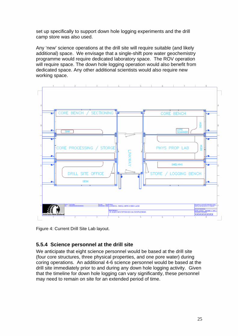
set up specifically to support down hole logging experiments and the drill camp store was also used. Any ‘new’ science operations at the drill site will require suitable (and likely additional) space. We envisage that a single-shift pore water geochemistry programme would require dedicated laboratory space. The ROV operation will require space. The down hole logging operation would also benefit from dedicated space. Any other additional scientists would also require new working space.
Figure 4: Current Drill Site Lab layout.
5.5.4 Science personnel at the drill site We anticipate that eight science personnel would be based at the drill site (four core structures, three physical properties, and one pore water) during coring operations. An additional 4-6 science personnel would be based at the drill site immediately prior to and during any down hole logging activity. Given that the timeline for down hole logging can vary significantly, these personnel may need to remain on site for an extended period of time.
25
5.6 Camp operation The following camp operation discussion assumes that the CH Project will adopt a similar operational model to that used during the SMS Project (i.e. minimal drill site science with the majority of the science team working at the CSEC, McMurdo Station). We acknowledge that an alternative operational models are possible but argue, based on experience, that any increase in drill site footprint is impractical and is not cost effective.
5.6.1 Camp scope and size The ANDRILL camp is currently optimised for about 36 people, and can accommodate some additional personnel for shorter periods of time. The camp needs to provide comfortable and quiet accommodation to support a 3+ month 24/7 operation where many personnel may only get occasional time off. The camp must operate successfully through a large range of temperatures and climatic conditions from spring through late summer (September-February). A comfortable camp is seen as critical to ensuring morale and retention of experienced personnel (over several drilling seasons). Facilities at the camp that are required include:
- quiet, warm sleeping areas with reasonable privacy and personal storage capacity
- food preparation and warm and cool storage areas - ablutions and laundry facilities including drying room (sufficient for daily
washing – drilling fluids are a messy business) - water supply and storage - dining area - lounge/relaxation area - reliable power supply (generators) - workshop and parts storage space - waste storage and sorting space - office space
If personnel were to increase significantly over the number used for the SMS Project, significant additional camp resources will likely be required. These additional resources would include space (sleeping, storage, and common areas) and support staff (such as chefs and domestics).
26
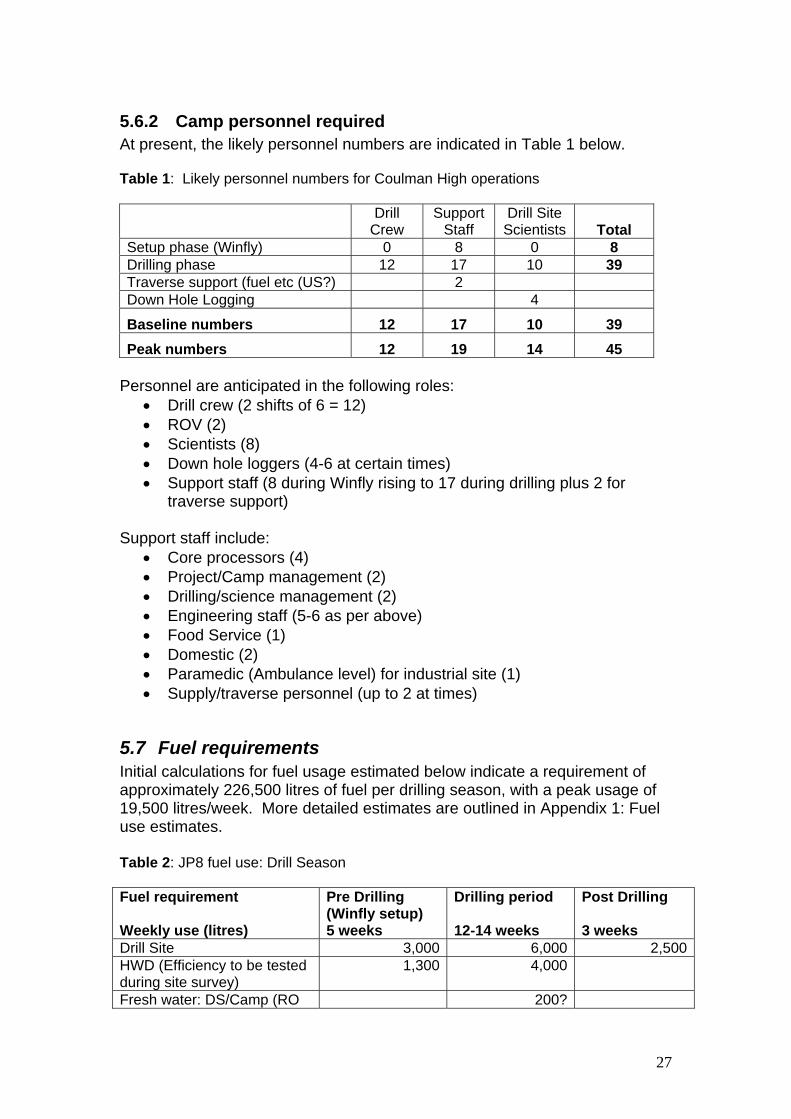
5.6.2 Camp personnel required At present, the likely personnel numbers are indicated in Table 1 below. Table 1: Likely personnel numbers for Coulman High operations
Drill
Crew Support
Staff Drill Site
Scientists Total Setup phase (Winfly) 0 8 0 8 Drilling phase 12 17 10 39 Traverse support (fuel etc (US?) 2 Down Hole Logging 4
• Drill crew (2 shifts of 6 = 12) • ROV (2) • Scientists (8) • Down hole loggers (4-6 at certain times) • Support staff (8 during Winfly rising to 17 during drilling plus 2 for
traverse support) Support staff include:
• Core processors (4) • Project/Camp management (2) • Drilling/science management (2) • Engineering staff (5-6 as per above) • Food Service (1) • Domestic (2) • Paramedic (Ambulance level) for industrial site (1) • Supply/traverse personnel (up to 2 at times)
5.7 Fuel requirements Initial calculations for fuel usage estimated below indicate a requirement of approximately 226,500 litres of fuel per drilling season, with a peak usage of 19,500 litres/week. More detailed estimates are outlined in Appendix 1: Fuel use estimates. Table 2: JP8 fuel use: Drill Season Fuel requirement Weekly use (litres)
Pre Drilling (Winfly setup) 5 weeks
Drilling period 12-14 weeks
Post Drilling 3 weeks
Drill Site 3,000 6,000 2,500HWD (Efficiency to be tested during site survey)
• Fresh water by RO at drill site has the lowest fuel requirement • Drill Site incl: Generator, Air heaters, Power pack • Drill site and Camp use: Based on relevant MIS/SMS operations (2006-07) • HWD use: Based on MIS ops, requires testing on thicker ice shelf (site survey) • Fuel Storage: ANDRILL Tanks, currently two 15,000 litre on Aalener Sledges
We propose that the fuel on site be stored in the two double skin tanks mobilised for site refuelling on Aalener sledges. Fuel resupply required approximately every 1.5 weeks would use 6-8 US Poly/bladder sledges, traversed from McMurdo/Williams Field.
5.8 Traverse development
5.8.1 Background – traverse capability and route development During the SMS Project, delivery of most of the drill site and camp equipment and regular supply of fuel and bulk consumables was provided by USAP Fleet Operations (FO). The SMS site was located 35 km from McMurdo Station. USAP traverse support including rudimentary road construction on the sea ice was incorporated within regular FO activity (general station and nearby airfields support) and was often tasked during the night shift. The CH sites are located 150 km from McMurdo Station. It is not considered realistic to support either Coulman High mobilisation or seasonal operations out of McMurdo Station/Scott Base with existing prime mover plant that are normally allocated to local operations. Dedicated ‘long-haul’ traverse equipment (similar to those used for the South Pole Traverse) will likely be needed to achieve CH traverse requirements. An estimate of the magnitude of the effort required is indicated below (section 5.8.1.3). Towing loads are expressed as ‘tow units’ that are equivalent to a 20 ft container on an ANDRILL Rigid Steel Sledge. Some loads such as the drill rig sledge are equivalent to 3 tow units and need to be pulled behind a D6 or equivalent prime mover.
5.8.1.1 Route The ideal route to CH will follow the existing McMurdo Station – South Pole route through and past the shear zone at which point it will turn northeast towards the CH sites (Fig. 1). The route would be flagged and dragged periodically in combination with traverse runs. The route is not envisaged as a high maintenance compacted road, consequently sledges and other traverse items will need to be optimised for soft snow surfaces. The use of part of the South Pole route would be formalised as part of the official
28
ANDRILL programme and if the staging scenario (described below) is adopted then most transit along this part of the route to Coulman high would be carried out by US McMurdo Fleet Ops. We would plan to mitigate the high volume traffic on the route by improvements to current ANDRILL sledge performance (poly skins) and also the routine use of grooming/drag equipment with the sledge trains.
5.8.1.2 Traversing scenario An alternative traverse scenario that may be more compatible with USAP FO is to establish a mid-distance staging point complete with overnight facilities. FO personnel/equipment would deliver ANDRILL tow units to this half-way point. ANDRILL tow equipment would then pick-up the units and deliver them to the CH site. This split-traverse strategy could enable optimal use of FO personnel and equipment by (1) enabling ANDRILL tow units to be moved to the mid point in a single shift and (2) providing flexibility in vehicle allocation (i.e. allow USAP the option to use more vehicles over a shorter time period vs. fewer vehicles over a longer time). Note that two dedicated ANDRILL prime movers based at the CH site(s) would be required to shuttle units from the mid point to the CH site.
5.8.1.3 Tow unit requirements • Site Survey season: Mobilise ~20 tow units from McMurdo Station to
CH for site survey operations (note this does not include seismic equipment and field camp). ANDRILL D6 LGP will be ‘permanently’ moved to the site during this season.
• Traverse season: Mobilise 80+ tow units. Twenty units coming south as ship cargo will require late season (February-March) traverse.
• Drill Season ACH1: Winfly traverse 6 tow units. Move drill site and camp units from winter storage to ACH1 site (~100 tow units). Re-supply site operation approximately every 10 days with fuel and drilling bulk consumables. Decommission and move drill site and camp to winter storage.
• Drill Season ACH2: Winfly traverse 6 tow units. Move drill site and camp units from winter storage to ACH2 site (~100 tow units). Re-supply site operation approximately every 10 days with fuel and drilling bulk consumables. Decommission and mover drill site and camp to winter storage.
• Completion: Either maintain equipment for winter storage in expectation of remobilisation to a new site or return all equipment to McMurdo Station (~100 tow units).
5.9 Drill season traverse operation The major traverse effort will be in the season preceding drilling operations, but fuel and drilling consumables supplies (in particular drill fluids products) will need to be traversed to the site during drilling operations. It is estimated that this would need to happen every 10 days. See section 5.7 for an estimate of fuel quantities and other issues.
29
Note that most science cargo items are fragile and/or no-freeze and are therefore unsuitable for transport by surface traverse that takes more than a few hours
5.10 Air support Air support to the site will be required for personnel and small cargo put-in and pull-out, and for regular core pickup. This support could be provided by helo and/or fixed wing aircraft. An “emergency” fuel supply for small aircraft could be maintained at the site, especially for aircraft that use JP8 (fuel most commonly used at the drill site). Additional fuel filtration capability could also be set up for aircraft use.
5.10.1 Personnel transport coordination Due to the length of the overland route to the drill site, we anticipate that most personnel will be put in to the drill site by aircraft. As at the SMS site, the majority of personnel will remain at the drill site for the entire season, unless there is significant ‘downtime’ for particular personnel (such as drill crew) between the first hole and re-spud in. In past projects, the down hole logging personnel arrived on site a few days before logging operations were anticipated to begin. Depending on the drilling strategy and the predictability of possible windows for down-hole logging, this group of personnel may need to be on site for a longer time period than in previous projects. Aircraft will likely be the primary mode of transportation for temporary visitors to the drill site (e.g. Science Team Members based at CSEC, DV’s, and Media). These visits may be coordinated with core transport flights (when space is available) or may require dedicated trips that will likely be scheduled out of McMurdo Station.
5.10.2 Transport of science equipment & supplies Several pieces of key scientific equipment (including core logging and scanning equipment) are both heavy and no-freeze and require air transport to the drill site. The majority of these pieces of equipment were flagged in the Operational Requirements Worksheet (ORW) submitted with the NSF proposal in June 2008. At least 3000 lb of air cargo were indicated in the ORW. (Appendix 2: ACH Air Support request).
5.10.3 Core transport coordination Air transport to the CH site may be by fixed wing or helo. Core pick-ups will be required daily or every two days, and will need to be coordinated with the return of empty core transport boxes. Coordination at both ends is required as the cores and other samples are temperature-sensitive. The majority of core should not be frozen but some samples may require ultra cold freezing.
30
If drilling rates similar to those attained during the MIS and SMS Projects are achieved at CH, then an average of 1800 lbs of no freeze core would be available for transport every 24hrs, with up to 2400 lbs on some days. There may be an opportunity to include small cargo items or visiting personnel on core transport flights, but experience gained during the SMS Project suggests that most core flights will be full.
5.10.4 Runway maintenance and snow clearing A runway/skiway may need to be maintained at the CH site, although this will depend on the type of air support provided. Past project operations have utilised the ANDRILL D6 to clear snow around the drill site and camp and site layout was planned to facilitate this activity. The D6 and Case 535 when on site could be used to clear snow for a runway although this may require significant personnel time (depending on the snow/wind regime at the site). Site survey data (surface accumulation) will help to plan for this additional snow moving activity. Additional equipment such as a drag that is compatible with drill site vehicles will be required.
5.11 Logistics coordination Effective communication and coordination between the ANDRILL drill site, McMurdo Station, and Scott Base was critical for operations during the MIS and SMS Projects. Effective coordination will be still be critical for the CH Project, although the remote nature of the CH site will mean that ANDRILL operations needs to be more self sufficient,. During set up and pack down, extensive coordination will be required. During the drilling operation there will be regular re-supply needs and cores will need to be picked up and returned to McMurdo Station on a regular basis.
5.12 Self supporting operation The Coulman High drill site and camp will need to be as independent from McMurdo Station and Scott Base as is practically possible. Re-supply or support from the US and NZ logistics hubs cannot be guaranteed with a quick turn-around. This fact has implications for the following key operational areas: personnel selection (such as inclusion of properly qualified medical staff); engineering support (site will need sufficient facilities to enable reasonably major equipment repair); parts supply; and fuel storage.
5.12.1 Engineering support The CH operation will need to be fully independent from McMurdo Station/Scott Base engineering support. Unacceptable delays to drilling operations and risk to successful completion could result if the remote site is reliant on support located at the bases.
5.12.2 Vehicle maintenance Engineering services (personnel) will run a regular field maintenance programme on vehicles used in the operation. The remote location of the
31
Coulman High site and a requirement that vehicles remain at the site for the entire operational period will require a higher level of routine maintenance than for vehicles normally based and operated from Scott Base or McMurdo Station. ANDRILL Site engineering staff should be appropriately qualified and the site supplied with sufficient tooling and parts. Additional support from McMurdo Station may be requested at times and may include machining services, short-term use of specialist tooling, and temporary assignment of a specialist mechanic for periodic vehicle maintenance.
6 Development and purchase requirements This section details the anticipated equipment development and purchase that will be required to support the CH operational strategy outlined above. It should be read in conjunction with the detailed recommendations on specific equipment items outlined in the MSP Project Close Out Report (Miller, 2008).
6.1 Drill system development – general
6.1.1 Rig/platform/power pack Details of the status of the Rig/Platform and Power Pack are outlined in the Close Out Report, and identify some items in need of replacement and/or repair. Further developments proposed for the CH Project include:
- Monitoring system. Modifications to monitoring system to include direct measurements of mud pump flow, replacement drill head and tide beam position sensing.
- ROV. Integration of ROV operations with drilling operations - New hardware. Dependent on Fast Drill/Re-entry decisions, the
following will probably be required: o re-entry cone deployment o sea riser monitoring for deployment
- Tide compensation. Modifications to allow the system to compensate for higher tides and higher ice shelf movement, and Sea Riser draw down with ice shelf movement.
- Mast Enclosure. Improved version with easier cold temperature erection, better high wind performance, and sectional repair capability.
6.1.2 Cellar and catwalk Details of the status of the cellar and catwalk are outlined in the Close Out Report, which identifies some items in need of replacement and/or repair. Further developments proposed for the CH Project include:
- A new cellar curtain (or modification to the existing one) to allow easier access for 3 m drill rod bundles and 6 m rod lengths.
Note that development work for the HWD system is outlined in section 6.2 below.
32
6.1.3 Mud supplies, mud system and pumps Details of the status of the mud system and pumps are outlined in the Close Out Report, and identify some items in need of replacement and/or repair. An inventory of mud supplies and other consumables is also included. Further development work for the mud system that will be required for the CH Project includes:
- new pumps, particularly to accommodate bigger capacity requirements for fast drilling and or re-entry operations
It will also be necessary to re-assess mud product requirements particularly with respect to fast drilling. Following completion of the SMS Project, mud products that degrade over time were returned to New Zealand and disposed of. Replacement products will need to be purchased for the CH Project. We would plan that fresh supplies of the time degradable products be shipping at the season prior to drilling.
6.2 Hot Water Drill – Mobilisation The ANDRILL Hot Water Drill (HWD) was originally designed for stationary operations linked to the drill rig platform. Its primary function was to penetrate the ice shelf and maintain an open hole for the sea riser deployment and sea water recovery for drill fluid production. Operation at the CH sites on the 250-300 m thick ice shelf will require additional hot water drill services to those required during the MIS Project operations. HWD requirements for an ice shelf operation (including both drill site and support camp) are itemised below (sections 6.2.1- 6.2.3). The total requirements for the HWD operations are in part dependent on the option chosen for fresh water production at the camp. However, in contrast to the MIS site, the HWD will be required to make several ice shelf holes at the CH site, in addition to directly servicing the drill rig operation. The current HWD design should be capable of these tasks if it can be configured for easy mobilisation between sites.
6.2.1 Drill site
6.2.1.1 Drilling The HWD will need to be capable of making a drill platform access hole and maintaining an open hole and sea water well for 60+ days. In addition, multiple holes maintained for 30+ days may be required if the sea floor re-entry strategy is adopted (see section 5). An option to use this sea water source at the drill site for camp fresh water production by Reverse Osmosis (RO) is also a strong possibility.
6.2.1.2 Drill fluid disposal Occasionally excess drill fluid or cement-contaminated fluid requires disposal. The HWD may be used to create a ‘shallow’ hole within the dense firn to provide a space to dispose of this excess (non-toxic) fluid and cuttings.
33
6.2.1.3 ROV Operations A hole for ROV operations will also be required separate form the main drill hole. This hole would either remain open during the period of drilling (60+ days) or be re-drilled and kept open for about 5 days at a time.
6.2.1.4 Down Hole Logging Down hole logging will be conducted through an ice shelf hole. Depending on the drilling strategy adopted, some wire line logging may be carried out by deploying tools through the water column and re-entering the sea floor holes after the sea riser has been recovered. This would also be conducted through a new ice shelf hole separated from the main drill hole. New tools that enable “logging while tripping” may also be used as these enable some bore hole wall data to be measured during normal drill rod trips without the additional time required for standard wire line logging set up. This new logging approach is currently under development supported by the International Continental Scientific Drilling Program (ICDP) and has potential for future ANDRILL operations.
6.2.2 Camp Fresh water production at the camp may require the support of the HWD. The options under consideration are outlined in section 6.5.2. Waste water is best disposed of into ‘shallow’ holes. Grey water could be disposed of into the dense firn but black water should be disposed of into a hole that extends into the dense ice. Future investigation and practical considerations will determine whether it is easier to create multiple smaller holes or a larger single hole and if the use of saline brine can improve waste disposal.
6.2.3 Mobilisation and operation of the current ANDRILL HWD Components and parts required to produce a mobile HWD system to service drilling (and camp) operation at Coulman High are likely to consist of the following existing and new components.
6.2.3.1 Existing Components • Heating Plant container and sledge (sledge may require replacement
with wider LGP sledge) • Hose Drum container #1. • Soft Shell enclosure • Capstans installed in cellar under the drill floor • Electrical & electronic control systems • 2000 litre double skidded tank
6.2.3.2 New Mobilisation and remote operations components • Duplicate Capstans and new Operations Container with sledge (May
be combined with ROV operations). • A second hose container to replace the soft enclosure that is not easily
mobilised
34
• 40 – 50 kVA self contained generator (mobilised back up for DS or Camp)
• Mobilisation sledge for Hose drum containers #1 & 2, fuel tank and generator
• Parts, pumps burners etc including field operation hose swaging tooling • Electrical & electronic control for duplicate capstans
Mobilization of the HWD services is critical to a successful remote ice shelf operation. If a second HWD were available it would still have to be mobile to service the camp, ROV and DHL holes and also be of sufficient size to keep these holes open for several days.
6.3 Engineering workshop capability For both the MIS and SMS Project operations, machining facilities at McMurdo Station and Scott Base were required to support drilling operations. Short turnaround times were often required. Given the remote location of the CH sites, reliance on McMurdo Station and Scott Base could cause significant delays in turnaround, which could compromise drilling operations. In addition the development and adoption of a specific new drilling strategy during the CH Project may require flexibility that only on-site engineering can provide. For example, re-machining an alternate sea riser thread may be required or other specialized equipment may need to be created or fixed. Turnaround for parts returned to McMurdo Station/Scott Base for work is subject to weather delay, which may put drilling operations at risk and should be considered an unacceptable risk. Therefore, we propose that additional workshop space (container and sledge) that includes a suitable sized lathe be commissioned to support the CH Project.
6.4 Science support
6.4.1 Drill site laboratory modifications A small additional lab space (one container) is required for interstitial pore water analysis, which was previously done at the CSEC. Accommodation for the pore water lab could be achieved by using the area previously allocated to drill fluids analysis. The drill site store could be converted to accommodate the Drilling Supervisor, Electrician office, and Lab IT support (i.e. Corelyzer). The store would need to be replaced with a separate heated container and sledge.
6.4.2 Down hole logging support requirements With the development of new drilling strategies for fast ice shelf movement down hole logging may be carried out away from the drill rig structure through a secondary ice shelf access hole to the sea-floor via the water column. A self contained operating container/sledge for winch and tooling is required for down hole logging operations. Ideally this new set up would still be compatible with the ‘traditional’ approach of logging through the drill string at the drill rig.
35
6.4.3 ROV operations container & sledge Operation of an ROV will be an integral part of new drilling strategy for Coulman High and thick fast moving ice shelf operations. A support container is required to provide sheltered operation for the ROV and winch. This would be set up 50-100 m from the drill rig. The container would require floor hatch and roof gantry.
6.5 Camp development The ANDRILL Camp consists primarily of containerised/modular and sledge-mounted units. Most of the camp components were built in 1995/96 for the CRP. Some additional units were built to support the SMS Project camp. As outlined in the Project Close Out report, several of the items require significant work or replacement. In addition, some items were on loan for the SMS Project and have been returned and some were disposed of and will need to be replaced. The camp infrastructure for the CH Project will need to withstand approximately six years of deployment and use in harsh environmental conditions including: two summer seasons of full camp operation, at least two over-winter storage years on the ice shelf, and two summer seasons for traversing (out to the site and back assuming the equipment is returned to the logistics hubs after completion of the two Coulman High drilling seasons). Given their current condition and the likely timeline for storage, traversing and drilling, and existing camp facilities need significant refurbishment or replacement. Some services such as water making will require changes from the sea ice based technology and improved mobility of some components is also desirable.
6.5.1 Sleeping facilities Many of the sleeping containers were fitted out for the CRP (using used porthole GRP containers) and have degraded over time. We recommend that a new 4 x 6 berth accommodation unit block (based on the Drill Site day camp design) be built. There are also safety concerns related to emergency egress in the old CRP sleeping containers and these concerns must be resolved.
6.5.2 Fresh water supply The ANDRILL Camp (and CRP camp from which it is derived) have thus far been established on sea ice and have used Reverse Osmosis (RO) systems to produce a fresh water supply from sea water at relatively low energy (fuel) cost. The ANDRILL SMS Project camp operation in 2007 supported 30 people on average and required a daily production of about 3000 litres of sea water. Heating of sea water to about 250C is required for the RO process and warmed sea water brine is a waste product. RO conversion of sea water to
36
fresh water is significantly more energy efficient than either melting snow/ice or sea water distillation (unless a large quantity of waste heat is available). Waste heat (hot air) from the air-cooled generators is currently used to heat living spaces and is not easily harnessed for “passive” snow/melting.
6.5.2.1 Ice shelf considerations At Coulman High on a ~300 m thick ice shelf a major consideration is the penetration of the ice shelf to obtain sea water and to keep that hole open. This is required for the drilling operation. A synergy could also be developed to provide a fresh water supply for the camp, using RO concepts previously applied at sea-ice based camps. Other options based on snow/ice melting include active snow melting incorporated into Camp buildings or recovering fresh water from melted ice in bulbs cut in the ice shelf. These would be made at ~ 40-60 m, below the firn-ice transition (40 m depth), and require use of the hot water drill. Further details of these options are given in Appendix 3: Camp fresh water options. The differences in the use of fuel for each option are significant. The estimates of fuel consumption are based on a daily fresh water production of 3 m3 per day over 95 days, the major part of a drilling season. Details of the calculations are shown in Appendix 4: Fresh water making options: First estimate of fuel usage. The RO option based at the drill site has the least fuel requirement with warmed waste brine used for drill fluid production and to help keep the main ice drill hole open. The RO option at the camp requires an additional ice shelf access hole, installation of submersible pumps and warmed waste water discharge that hopefully will keep the access hole open. The increased fuel use for this option reflects these additional requirements. The ice shelf melting option requires is the most fuel and is based on a 50% efficiency (2.0 multiplier) of the hot water drill melting, based on an approximate measure used in Ice Cube (Robin Bolsey pers comm.) This efficiency will be tested specifically for the ANDRILL HWD during proposed site survey field programmes and the fuel estimates revised if necessary. It is likely to also require multiple holes to be made in a drill season. The estimate for fuel required for the snow melting option is still nearly four times that of the most efficient RO option (at the Drill Site). The efficiency factor for this option is not yet well defined because it is not based on existing equipment and recent operational experience. Currently a multiplier of 1.5 is used given that the snow melting system requires dedicated fuel fired heating and that waste heat is unlikely to be available to supplement the snowmelter.
37
Recommendations: • RO at the drill site appears to have the lowest fuel use and highest
synergy with other drill site operations, but this should be confirmed by engineering analysis
• The RO capacity should be sized to allow catch up due to downtime for equipment failure or maintenance. A double RO system should be considered to ensure operation if equipment fails or requires significant maintenance. Maximum capacity should be 2-3 times estimated daily use.
6.5.3 Other camp facilities The MSP Project Close Out report outlines several other facilities that require modification or replacement. Once the scale of operations at Coulman High and personnel numbers are better known, a careful inventory and review of camp facilities will be required to determine what improvements or additional facilities are required.
6.6 Vehicles
6.6.1 Prime Mover Plant ANDRILL heavy plant assets currently consist of only one D6R LGP and a small tracked Multi Terrain Loader (MTL) (Cat 247B) that is used to move equipment at the drill site camp and support the Hot Water Drill operations. Only the D6 is suitable for towing and on the ice shelf snow route can probably tow at 6-8 km/hr with a maximum load. The D6 has fitted a snow blade and has been used primarily to move snow, set up the drill site and camp and build snow beams for winter storage. It is probably not the ideal vehicle for long traverses as it would be slower and be left behind the faster more powerful specialist towing prime movers. The US programme is currently operating CASE IH Steiger 450 & 535 Quadtrac and Caterpillar Challenger 95 tractors both in the local McMurdo area but also for South Pole traverse operations. These vehicles with 3 & 4 tow units can probably travel on a partially prepared route at a speed of about 10 km/hr. If vehicles such as the CASE IH Steiger 535 Quadtrac are used then a turnaround of about 5 days (McM - CH - McM) to allow loading and unloading and could be used for initial planning purposes. Details are shown in Table 3. Table 3: Tow units and prime mover options Activity Tow Units 1 Prime
mover 2 Prime Mover
4 prime mover
Site Survey 17 total 5 trips 25 days
3 trips 15 days
1 trip 5 days
Mobilisation (Traverse season)
80 total 23 trips 115 days
11 trips 60 days
6 trips 30 days
Drill Season Regular supply
6 per trip 1 trip every 14-20 days
38
New season supply (February)
6 per trip 2 trips 10 days
Turnaround times for vehicles based out of McMurdo Station could be halved if a mid-way station were established. However, this would require two traverse tractors to be based at the CH site rather than McMurdo Station.
6.6.2 Timing and currently available traverse resources The main activity of the Antarctic summer season is carried out in the McMurdo region from early October to late February. In this period McMurdo Station fleet resources (machines and personnel) are primarily engaged in sea ice runway construction and operation, snow road and skiway (Williams Field) maintenance and Pegasus airfield maintenance with ship operations in early through mid February. The South Pole traverse which uses similar vehicles to those suggested here for ANDRILL operations is expecting to operate two or three traverses per season eventually. These vehicles are therefore away from the McMurdo area for all of the 120 day USAP summer field season (Weale and Lever 2007) and could not be expected to contribute to ANDRILL mobilisation unless this was carried out by winter crew in late February or March using South Pole traverse vehicles. The conclusion from this short discussion is that local McMurdo Fleet Operations including any minor contribution from Scott Base heavy plant will be unable to mobilise ANDRILL Equipment to Coulman High in a single season unless additional heavy towing plant is provided specifically for ANDRILL. The site survey and drilling years will also require constant support from heavy plant in addition to the single D6 already in the ANDRILL inventory. A way forward is to add two new vehicles (Case IH Steiger 535 Quadtrac), either purchased or leased for at least 5 years to the ANDRILL inventory for mobilisation and drilling years (and perhaps also for site survey). In addition these will need to be supplemented during the mobilisation years with two vehicles from McMurdo fleet operations for one month in the five month summer season. Beyond CH for future drilling projects, two Case tractors would still be required, particularly to service any ship offload operations. The long-term vision for ANDRILL post-CH may influence lease or purchase decision making.
6.6.3 Other heavy plant requirements The Cape Roberts Project operated a HIAB crane on a Kassborer tracked vehicle. The crane was a very versatile item of equipment, especially in a remote field location. ANDRIILL thus far has operated a small tracked forklift (MTL) for all lifting requirements with an 800 kg fork limit. At times a crane would complement the forks capability for heavier lift items and be able to provide a more efficient and safer insertion especially for items that required
39
moving in containers or on the catwalk (such as logging winches). The Case STX530 is a sufficiently heavy vehicle to be a good base for a large HIAB to provide a remote operation medium lift capability on snow surfaces that require tracked vehicles.
6.6.4 Other vehicles
6.6.4.1 Hagglunds ANDRILL currently has a single Hagglund vehicle used primarily for personnel transport. During drilling this vehicle is used several times a day between camp and Drill site and also would likely have a role for runway maintenance. A second permanent Hagglund vehicle will be required during the Winfly and set up periods but also during normal the drilling period for heavy vehicle escort and activities between Drill site/Camp winter equipment site and the next (CH2) site.
6.6.4.2 Skidoos ANDRILL currently has four skidoos purchased in 2003-2004. Four machines are probably sufficient for remote Camp and drill site operations. However some maintenance is required and possibly the purchase of spare parts for field based operations. Consideration should also be given to replacement, especially if these machines get further use during site surveys that happen prior to the Coulman High project becoming operational.
6.6.5 Recommendations • Establish the availability of prime mover resources in kind early in the
project planning process because a lack of resource will delay or extend the time required for the traverse season.
• Two CASE IH Steiger 535 Quadtrac are purchased or leased for the ANDRILL CH to partly service mobilisation and also 5 months of operations in the two drill seasons. Supplemented by heavy towing plant from McMurdo Feet operations for the site survey season if ANDRILL plant is not available and for half of the mobilisation season effort.
• One of these CASE Tractors be fitted with a Hiab. • A second Hagglund personnel carrier is required for Coulman High
operations. • A replacement programme for skidoos should be considered to ensure
that four machines are available for the site survey and subsequent drilling seasons.
6.7 Sledges Most of the existing ANDRILL sledge units are built from steel sections (I beams) in various combination of widths and lengths and are therefore steel soled. Many of the units were inherited from the Cape Roberts Project where sledges were built primarily for sea ice operations and minimal snow cover. These sledges did not perform well in thick snow and the new sledges built for ANDRILL improved on the CRP designs with higher runners (410 mm) to sit
40
above soft snow, a longer and larger radius (1.6 m) front ski curvature to lift out of wallows and slightly wider soles. Some of the very light, shallow and narrow CRP sledges were replaced completely and the heavier sledges had blocks fitted to lift the transoms, effectively making higher runners. The modification of the CRP sledges was an improvement but the heavy units such as the rod sledges and Drill Site services containers still perform poorly compared to the newer designs. Several of these sledges are likely to have high drag coefficients in the soft snow conditions that are commonly found on the Ross Ice Shelf (see Weale & Lever for discussion of snow and towing conditions). If these units remain difficult to tow, the ability to move all equipment to the drilling site in the traverse season will be compromised, and/or require an impractically large allocation of traverse support from FO. US initiatives for the South Pole traverse have also developed new sledge concepts by using sheet polyethylene (HMWPE) for large surface area sledges where the polyethylene has a low friction coefficient on snow. This material could also be used for a relatively cheap and temporary modification to existing steel sledges by making “removable snow skins” to fit the steel skis for long distance traverse, thereby increasing the number of sledge units that can be efficiently towed by large prime movers. Snow skins can be removed to enable sledges to be tracked on hard ground without major damage to the sliding surface. Details of existing and new sledges are shown in Appendix 5: Existing sledges by model and estimate of new sledges required.
Recommendations: • If required, new steel sledges should be built with the recent design
improvements. • Removable snow skins should be built for existing steel sledges to
improve long traverse performance.
6.8 Fuel tanks and fuel sledges Currently ANDRILL has two 15,000 litre double walled JP8 tanks fitted to Aalener cargo sledges. These tanks fulfil NZ standards for long-term fuel storage. This capacity (30,000 litres) is estimated to be sufficient for 1.5 weeks operation at Coulman High. New bulk supply (traverse from Williams Field) and site containment is required. Fuelling to the remote site is expected to be carried out by vehicle traverse every 2-3 weeks during drilling operations. We propose:
• The two 15,000 litre tanks are used for long term supply at site including Winfly start up and late season decommissioning.
• New US bladder tanks (6 to 8 bladders each 10,000 litres) on sledges are purchased for regular traverse supply and short term storage at site.
• Fuel transfer systems between bladder and rigid tanks are required.
41
• A smaller supply of Mogas for Hagglunds vehicles, skidoos and small engines will also be required.
The estimates of fuel usage, and therefore storage and traverse capacity required, are estimated based on current expectations. Data from drill testing and HWD site survey operations may change fuel use estimates.
6.9 Drill Site and Camp Power Generation
6.9.1 Power generation A stable and reliable source of electrical power is a primary requirement for the continuous operation of both the drill site and camp. Several components of the drilling system operation are also independent of the Drill Rig hydraulic Power Pack and require electrical power. In the MIS operation only the drill site (not the camp) was operated and drill site personnel were accommodated at Scott Base and McMurdo about 12-15 km away. No major electrical generation or other drilling system issues occurred during the MIS operation. In the SMS operation both the drill site and a camp for drill site personnel were operated remotely (35 km) from Scott Base and McMurdo Station. In total between the two sites, five generator units were available, two 75 kVA units at the camp, a 75 kVA and a 100 kVA at the drill site and portable 17 kVA generator. The three 75 kVA units were refurbished from the Cape Roberts Project, the 100 kVA and 17 kVA units were new in 2006. The four larger generators comprise VM Sun series air cooled engines that enable flexible field maintenance and individual replacement of cylinders and associated components. During the drilling operation the 100 kVA unit failed twice overlapping with one of the camp units which also failed. All failures were related to broken valve springs but caused significant damage requiring replacement of three individual cylinders and heads. Replacement parts were sourced from New Zealand, Australia and the USA but took weeks for all parts to be sourced. During the period of prolonged breakdown the portable generator was kept heated and could be plugged in at either camp or drill site within half an hour to ensure vital operations could continue. At no time was the camp or drill site operations curtailed by power generation. The exact reason for failure of the several of valve springs in one season is not clear however it may be related to winter cold storage of equipment. A start up strategy to replace these items after winter storage should mitigate these problems in the future if these generators are used. ANDRILL operations planning continued and built upon the flexible power generation strategy originally designed in the CRP operations where backup and alternative systems are available onsite. The SMS power generation problems have shown this strategy works if sufficient parts and support are available for field maintenance. It has also highlighted what parts of the drilling
42
and camp systems in addition to power generations are most vulnerable to breakdowns and that reliance of parts sourced from NZ or further abroad cannot be relied upon for a 24/7 remote field operation. The same strategy to have alternate options to solve drilling related problems has been and should be applied in the future by ensuring that problems can be solved in the field without major loss of time in the drilling operation. Recommendation
• Review both the drilling and camp systems to identify and resource back up alternatives for critical systems
• Continue with the flexible backup strategy approach to power generation for both camp and drilling operations
• Hold stock of major spare parts on site
6.9.2 Generator requirements Requirements for existing and new generators are shown below in Table 4. Table 4: Generator status and requirements Site/operation Existing @ Feb 2008 Action Comment Camp VM Gen 1: 75 kVA Repair? Uses oil Camp VM Gen 2: 75 kVA Replace Old = Parts Drill site VM Gen 1: 75 kVA Replace Rebuild = Spare (1)
Drill Site VM Gen 2: 100 kVA OK Parts replacement programme
Mobile Deutz Gen 1: 17 kVA Parts replacement programme
HV Pumps New (80 kVA req.) Purchase compatible
New Capacity & Backup (1)
Mobile/HWD New (~ 50 kVA req.) Mobile (2)
(1) Electrical powering of new High Volume Pumps required for new riser and drilling strategy may not be the most economical option but provides the highest flexibility for pump control and backup power generation. At the drill site, a second 100kVA unit to replace 75 kVA drill site unit may be an option with a switchable power line directly to the pumps. (2) Mobile unit primarily to power the HWD when not at the drill platform and ROV and remote down hole logging operation.
7 Timeline/programme A high level timeline showing phases of development and operation is shown below (Fig 5). Three major deadlines are indicated: a January 2010 deadline for major equipment to be ready for shipping to Antarctica for traverse the following summer, a later deadline of January 2011 for remaining equipment to be ready for shipping and traverse in the latter part of the 2011/12 season, and an airlift deadline of Sept 2011 for final equipment to be airlifted to the site.
43
The current plan incorporates commencement of development activity during 2009. However, if funding is not available in the early part of 2009 the entire programme will slip a year.
Figure 5 High level time line for Coulman High Project Operations
7.1 Presumptions The time line for project development and operation is based on the following presumptions:
1. Site Survey. That a site survey will be conducted to collect data to feed into operations analysis and that this analysis confirms the feasibility of currently proposed drilling strategy, drilling operations plan, and engineering preparation. Preliminary design work for both drilling and operations can be carried out prior to site survey work and data analysis. This preliminary design work will enable fabrication of equipment to begin soon after the site survey is completed. This will allow fabrication to be completed during the year and will provide time to get the equipment to Antarctica and traverse it to the CH site during the following traverse season.
2. Traverse Season. Operations management and logistics coordinators
accept our recommendation that equipment be traversed to Coulman High on the Ross Ice Shelf. The traverse will follow a 155 km route
44
from McM/SB to Coulman High via the existing South Pole route through the shear zone east of White Island-Ross Island. The 2+ month traversing time requirements mean a dedicated summer season is required to get the bulk of the ANDRILL drilling equipment and camp to the CH site. Alternate equipment movement by ship; on-load at McM and offload (Ross Ice Shelf front) is not considered viable because of the relatively short transit distance and lack of suitable ice front access in the vicinity of the CH sites.
3. Funding. That funding will be made available in a timely manner to
support preparatory planning and engineering tasks, site survey operations, and allow seamless design completion and equipment purchase in preparation for shipping to Antarctica. Even if funding is made available to meet objectives and milestones we anticipate that a significant traversing operation will still be required prior to drilling in the first drilling season. If funding is delayed then initial planning will also be delayed, likely causing set backs in site survey etc. The entire plan will likely be slide at least one year.
4. Winfly. That Winfly deployment will be available for ANDRILL
operations personnel. Drilling operations will almost certainly require the spring and early summer period (August-September) for traversing and setup for the drill seasons.
Conclusion: Given the best case scenario for project funding, the earliest that drilling could begin is toward the end of the third austral field season following initiation of the planning and design phase.
7.2 Key milestones/constraints & implications for delays In developing this indicative timeline, we have identified that funding is a critical constraint as follows:
• Early funding for initiation of the design and planning phase is required, given the long lead time for equipment design, manufacture, shipping and traversing. Some of the residual MSP funds could be invested in the early planning phase, but this may only buy 3-6 months of time.
• Traverse capability currently available from McMurdo Station and Scott Base is insufficient to support an operation at Coulman High. Two dedicated prime mover machines will be required by the ANDRILL Project as well as traverse resources from the USAP Fleet. Purchase of any new traverse equipment will be required 1+ year prior to the Traverse season (given shipping/sea constraints) unless air lift is used at the beginning of the traverse season. The substantial funding commitment for this equipment alone suggests that a significant portion of project funding will need to be in place prior to November 20 09.
Conclusion: Any disconnect between funding and key project start dates and milestones will cause delays in the project timeline and ultimately when the first drill season can occur.
45
In addition, timely access to air and ship cargo is critical: • Air cargo will be required for the site survey season, the traverse
season and first drill season • Timing constraints for sea shipping will force some key pieces of
equipment that require site survey data input prior to design and build to be traversed to CH during Winfly in the first drill season.
Finally, site survey data acquisition is critical to maintaining the timeline. The data acquired from site survey (particularly, though not only, current measurements) needs to be analysed with respect to safe operational practices for the sea riser.
The following solutions go some way to addressing the constraints described above:
• Initial drilling and operations planning and design (prior to site survey results) could be funded in part using MSP reserves.
• Some ANDRILL Project work could be completed at Scott Base over winter by ANDRILL personnel. This option allows purchase & shipping of some items to be delayed. Completion of any remaining work associated with these items would be done during the winter prior to the first drilling season.
• Some equipment could be transported to the site in February (particularly applicable for equipment shipped by sea during the traverse season).
• Traverse some equipment to the CH site during Winfly prior to beginning of drilling.
• Utilize Winfly and Main-Body airlift to move equipment from NZ to Antarctica. This approach would accommodate any disconnect between funding required for timely purchase of equipment and the limited sea cargo time frame.
8 Financial
8.1 Background The last two international collaborative projects of this type (Cape Roberts Project and the ANDRILL MSP) both used a financial model for logistics and operations support that is generally compatible with National Antarctic Programme budgeting. The key feature to note is that science funding is separated from logistics support costs. Discussion below is intended to establish a starting point on which to build the next ANDRILL Project Budget..
8.1.1 Operations costs The cost of acquiring the core; primarily the field preparation, drilling operation and the majority of logistical support for drill site science was supported with funds transferred from National Antarctic Programmes logistics and operations budgets to the Project Operator Budget. The Project Operator reports to the ANDRILL Operations Management Group (AOMG) comprising representatives from the National Antarctic Programme consortium.
46
These costs included both capital (equipment development and purchase) and operational (consumables and staffing) costs. Some non-drill site infrastructure costs were included in the operations budget – notably costs to develop and install the core splitting facility at McMurdo Station.
8.1.2 Science costs These are costs associated with the on and off-ice scientific work and may include seismic data collection, core/sample analysis, and down hole experiments. Funding to cover these costs is generally provided in the form of science grants from National Funding Agencies to individual PIs, collaborative PI programmes, and (in the case of the US) to the ANDRILL SMO on behalf of the US ANDRILL Science Community.
8.1.3 Operations/science overlap An operations/science funding ‘grey area’ exists where some activity/costs overlap. An example of this overlap occurs within the site survey budget category where a field operation may support activities to generate a scientific outcome (e.g. seismic data generation and interpretation) and activities that generate data required specifically to plan and operate at the site (e.g. radar and oceanography). The attribution of costs in these cases is normally subject to negotiation. Funding amounts usually represent a small fraction of the total operations or science budgets.
8.1.4 Site survey Past AOMG agreements have not attributed the science cost (funding) of site survey to the project operations budget. The general principle has been that all site survey activities required to prove that a site is scientifically valid are supported via science funding (and attached logistic support). Operational site survey specifically required to operate at a site is funded from the project operations budget.
8.1.5 Resources in kind (RIK) RIK represent resources or support that are/is available through ‘regular’ National Programme activity that can be allocated to the project to supplement ANDRILL operations at no extra cost to the National Programme. Where additional resources (personnel or capital assets) are required to supply a “resource in kind” to the project the incremental cost for that resource has been charged against the project operations budget. In previous activity in the Ross Sea region (e.g. CRP) accounting RIK has provided a perceived advantage to those National Programmes that have ‘local’ capability, e.g. US, NZ and Italian Programmes. In all previous drilling projects, RIK has only been considered within the operations budget. RIK has not been considered within project scientific budgets.
47
8.1.6 Contingency Contingency changes with time to complete and the forward planning period. A process for allocating contingency should be included in the project plan and subsequent budgets.
8.1.7 Escalation Over the last several years, the world financial climate has seen a major escalation in costs for many items such as oil and steel/minerals. For a drilling operation this escalation has both a direct and an indirect impact. We require materials such as steel for construction of equipment and a supply of drill rods. The cost of personnel also increased significantly during the MSP. ANDRILL competes in an international market for both drilling equipment services and personnel.
8.2 International contributions During previous projects, national contributions to an operations budget have been used to determine national scientific involvement (i.e. scientific staffing). However, it is not within the scope of this document to address the mechanism or implications for international contributions to the operations budget.
8.3 Budget considerations A preliminary Operations Budget could be developed based on ANDRILL MSP costs and current best estimates of costs for new items. The Coulman High operations will be more remote from McMurdo Station than during the MSP. Relevant experience from CRP should also be considered. RIK contributions will need to be identified and agreed for some components of the budget. It is acknowledged that for future operations including Coulman High, RIK contributions are likely to be revised based on specific project requirements and capabilities of partner programmes. The budget would primarily outline the cost of operations to ultimately recover core from the Coulman High sites. Past ANDRILL budgets did not include the majority of science costs. There are costs are associated with coordination between drilling-science requirements and research operations engineering/science that could be included in the Operations budget. 8.3.1 Budget categories Planning costs:
The costs could be based on the ANDRILL McMurdo Sound Portfolio as reported in the Antarctica New Zealand Project Close Out Report. The following items would be included within this category: • Project Operator costs • Drilling Science coordination • Project Engineering –Drilling • Project Operations Engineering
48
Equipment - scoping & design:
• CH drilling engineering requirements, research, drilling strategy and equipment design to enable drilling at CH using existing technology and ANDRILL assets as a basis. Two primary options, fast open hole drilling and sea floor re-entry are considered most viable at this stage.
• HWD: Using existing ANDRILL assets and primary capability, modifications for 300+m thick ice shelf and mobilisation to service ROV and camp requirements.
• Remote camp operations and services integration Drill Site and Camp. Using existing assets as basis, thick ice shelf &remote operations adaptations with integration of DS services etc.
This category is directly dependent on results of the Research and Design (above) and may be less well constrained. • Drilling System: Costs should be estimated for modification/repair
primarily of existing equipment and capability for CH Operation. • Drilling Strings and Coring: Estimates based on a management
programme for sea riser and drill strings where an active string safety factor and anticipated loss as casing is applied. Estimates for standard down-hole tooling anticipates normal wear and replacement of parts during drilling for two seasons
• HWD: Modifications to capability for operation through a 250-300 metre thick ice shelf, improved mobile operation to service Drill Rig, ROV, down hole logging and Camp (water supply waste disposal requirements).
• ROV Support: Required for CH operation whatever drilling strategy is adopted. ROV development (US-Moss Landing) specifically for narrow ice hole access. Plus ANDRILL equipment cost for ice shelf deployment.
• Drilling Strategy. Estimates of major new capability (common and unique equipment) for both options.
Mobile Plant: Costs for proposed purchase of two prime movers and new sledge & fuel units dedicated to ANDRILL CH operations. [The CH traverse scenario proposed in this document would also require McMurdo sourced RIK resources – See Operations Cost]. 8.3.2 Priority for initial funding The following list prioritizes immediate and short-term funding needs to maintain a realistic drilling timeline.
1. Sea Riser Modelling Phase 1 2. Fast Drill tests & equipment scope 3. HWD Design (Site Survey & Mobilisation) – Site survey - Maintenance 4. DS & Camp Power generation & Water option - Decisions & Design 5. Camp Accommodation, design and purchase (components?)
49
9 Project Management The following comments are intended as a guide for development of future project management structure. The comments are based on lessons learned from prior experience but by no means represent all possible management solutions.
9.1 Project Management/Project Operator A project as complex as ANDRILL Coulman High requires dedicated Project Management. For the ANDRILL MSP this was provided by Antarctica New Zealand as Project Operator supported by expertise from the Antarctic Research Centre at Victoria University of Wellington. Project management staff at Antarctica NZ worked closely with staff at the ANDRILL SMO and USAP logistics contractor (Raytheon Polar Services Company). We recommend that previous experience be utilized to develop future project management structure as these management models have been highly successful. Due to the particular requirements of operating in Antarctica (logistical and legal), it makes most sense for an Antarctic National Programme to be designated Project Operator. The designated Programme will manage project operations on behalf of the partner countries. Antarctica New Zealand currently manages the existing ANDRILL equipment and has a proven track record for success as Operator of previous drilling projects. Therefore it seems sensible that Antarctica New Zealand be asked to continue in this role for the Coulman High Project. The Project Operator will be responsible for coordinating overall project management, which would include oversight of the budget, engineering development, operational logistics (planning and on the Ice, in conjunction with National Programmes) and operational staffing. While the overall project operations management responsibility would lie with the Operator, aspects could either be contracted to suitably experienced organisations or done by staff employed by Antarctica New Zealand. Note that Science Management and science coordination will be maintained at the ANDRILL SMO, University of Nebraska – Lincoln, USA.
9.2 Drilling contractor – pros and cons Drilling projects are often managed by engaging a Drilling Contractor. The Drilling Contractor is responsible for staffing and managing the drilling operation to achieve the requirements outlined by a client representative. Contractors provide a single point of contact and are usually familiar with the operating environment. The unique operating constraints of Antarctic work (such as the fact that it is difficult to rotate personnel in and out) and the need for some personnel to have past Antarctic drilling experience have precluded using a traditional contractor approach in the past. In addition, few contractors have the relevant Antarctic experience.
50
Senior drilling personnel from the SMS Project have indicated that there would be little advantage in managing future drilling operations by engaging a Drilling Contractor. Such a contract provides little financial incentive for the Contractor and also limits the ability and scope to select appropriate drilling staff.
9.3 Environmental Management A Comprehensive Environmental Evaluation (CEE) for the ANDRILL MSP was produced by the Project Operator, Antarctica New Zealand, for the first two ANDRILL Projects (Huston et al, 2006). A draft CEE was considered by CEP/ATCM in 2003, and the final CEE circulated in June 2006. As the bulk of the ANDRILL equipment and operating strategies are envisaged to be similar for Coulman High, it is anticipated that this document will provide the basis for any future CEE. However, the long lead times for international consideration of any CEE means development of this document must be an early priority for the project. Production will be coordinated by the Project Operator with input from environmental and technical specialists. An additional advantage in developing the CEE early in the project is that operational constraints can be identified at an early stage. As a result, appropriate planning and resource acquisition to mitigate these constraints can be implemented in an efficient and effective manner. We recommend that development of a generic CEE for ANDRILL operations should be considered. If a new CEE is well conceived and generic in nature, future individual drill sites would likely not need to be vetted through the entire CEE process. Any site specific modifications would be noted via an Initial Environmental Evaluation (IEE) process.
10 Risks The following major operational risks have been identified. These items have significant time or cost implications. This section does not provide an exhaustive list of risks, but highlights events that are currently foreseeable and would have a major adverse impact on the project. 1. Funding for operations is not forthcoming within reasonable timelines. We have identified that funding for development work needs to be available at least three years before drilling can commence. It seems unlikely that this timeline could shorten but it could certainly lengthen. 2. Sea riser modelling using actual current data obtained during site survey identifies that a new approach or new equipment for sea riser embedment will be required that is not currently being considered in the two drilling strategy options. This could result in significant change to the budget and/or delays to the timeline.
51
3. Delays in getting equipment to the ice Could be due to hold-ups in production or the lack of available of cargo space (air and/or ship) 4. Significant crevasses are located inland of the proposed drill sites, at the drill sites, or along the traverse route. Safety concerns about calving of the ice shelf front could lead to delay or cancellation of the project at any stage. 5. Seismic crossing lines identify potential reservoirs in the target sequence. This would likely cause the cancellation of drilling at that site. 6. Environment Evaluation is not approved by the Antarctic Treaty System. Modifications to project plan based on feedback from CEE could be implemented but significant delays would be likely and cancellation possible. 7. Operational problems such as loss or failure of major equipment during drilling.
52
11 References Cowie, J. (Ed.) (2002). Cape Roberts Project Final Report 1995-2001.
Christchurch, Antarctica New Zealand. Huston, M., Gilbert, N. and Newman, J. (Eds.) (2006). Final Comprehensive
Environmental Evaluation (CEE) for ANDRILL McMurdo Sound Portfolio. Christchurch, Antarctica New Zealand.
Miller, I. (2008) ANDRILL Southern McMurdo Sound Portfolio Project Close-
Out Report. Antarctica New Zealand for AOMG. Padman, L., Erofeeva, S. and Joughin, I. (2003). Tides of the Ross Sea and
Ross Ice Shelf Cavity. Antarctic Science 15 (1): 31-40. Pyne, A. and Falconer, T. (2008). ANDRILL Drilling Review: MIS 2006-07 &
SMS 2007-08. Report presented to AOMG July 2008. Robinson, N. & Pyne, A. (2004). Water Column Current Profile Analysis from
beneath the McMurdo Ice Shelf at Windless Bight and under the sea ice in Granite Harbour, Antarctica. Antarctic Data Series #26. Victoria University of Wellington, Antarctic Research Centre.
ACH USAGE # days usage wkly rate # days usage wkly rate # days usage wkly rate TOTAL Pre rate same as Post
DS Generator (incl jet burner) 35 12,500 2,500 75 39,520 3,689 20 7,143 2,500 59,163 Pre&post is estimated betw MIS & SMSPower Pack 35 2,523 505 75 23,038 2,150 20 1,442 505 27,002 Same as SMS rate for drillingHeavy Plant general usage 35 3,105 621 75 2,506 234 20 1,774 621 7,385 Use SMS estimates (higher)Heavy plant winter site 1 3,600 1 3,600 7,200 Moving 10km to/from winter siteCamp Generators 35 4,949 990 75 18,733 1,748 20 2,828 990 26,511 Camp Preway 35 630 126 75 2,822 263 20 360 126 3,812 HWD for drilling & ROV 1 9,000 95 52,929 3,900 61,929 2 reams/wk for drilling, 1 for ROVHWD for fresh water 95 35,286 2,600 35,286 2 x 6hr operation (equiv to ream)
Alex Note: DS RO fresh water fuel = 120 l/wTOTAL 36,307 19,500 228,287
SITE SURVEY Initial hole creation During operationHWD 1 9,000 35 19,500 3,900 28,500 Initial hole then 3 reams/wkDS Generator 35 10,792 2,158 10,792 Usage based on SMS predrilling phaseTOTAL 39,292
54
12.2 Appendix 2: ACH Air Support request Drilling Operations – Site survey and drill site operation Produced by Tamsin Falconer, Alex Pyne, Victoria University of Wellington June 2008 In previous ANDRILL drilling operations, the following type of support was requested via the Operations Management Office at Antarctica New Zealand, so would not have been included in the US SIP. This information is included pending decisions on allocation of support. Flights could be either Twin Otter or Helo. 2009/10 Season – Site Survey Item Flight
keep open in the ice shelf Warm brine used for drill fluid and over flow to keep hole open Minimal labour content additional to drill and normal camp ops. Probably least fuel required
Fresh water transport to camp with two Container & 15 m3 bladder (new) Sea Water buffer container & 15 m3 bladder (new) New RO self contained module (container and sledge) at DS. Additional power requirement at DS but offset by HWD mobilisation requirement. RO ops regular checking at DS from Camp Personnel?
HWD: Drill site and periodic ROV operations MTL at DS
RO at Camp
Mobile water storage system not required
Not clear if waste heat output is sufficient to keep the intake hole open. Potential intake filter contamination from nearby waste grey water discharge at the firn-ice transition.
HWD required periodically to melt and keep the sea water intake and return ice hole free MTL required intermittently
Ice Bulb Large volumes of clean water made in a day.
High fuel use to melt ice, dependent on HWD efficiencies Container & 15 m3 bladder High labour component (3-4 days) Probably most fuel required, assuming a 50% efficiency of the hot water drilling melting process.
HWD Required and mobilised regularly. MTL Required 3-4 days with HWD
Snow melting
Integral part of the Camp
Contaminated snow from nearby Camp emissions and activity High hourly labour component , regular feeding Takes MTL away from Drill site
MTL required hourly
57
12.4 Appendix 4: Fresh water making options: First estimate of Fuel Use Note: Calculations require confirmation by heating engineering analysis
R/O at Drill Site
R/O at Camp
Ice Shelf Melting
Snow melting
Heating Estimated Energy Req./m3 fresh water (MJ) 111.00 111.00 457.00 457.00Efficiency multiplier (inverse of fuel GCV efficiency) 1.33 1.33 2.00 1.50Energy from fuel (GCV) 147.63 147.63 914.00 685.50Electrical Electrical Req. RO pumps/m3 fresh water (MJ) 24.00 24.00
HWD equipment 24.00
Electrical Req. Submersible pump/m3 fresh water (MJ)
Drill fluids equipment 144.00 39.27
Electrical/Fuel equivalent multiplier (= inverse of fuel GCV efficiency) 1.67 1.67 1.67 1.67Electrical total /m3 freshwater (MJ) 40.08 280.56 65.58 40.08Fuel Fuel Energy required (MJ) 187.71 428.19 979.58 725.58Kerosene GCV (MJ/litre 35.00 35.00 35.00 35.00Fuel /m3 freshwater (litres) 5.36 12.23 27.99 20.73 Operating days per Drilling season 95.00 95.00 95.00 95.00Total fresh water requirement (@ 3 m3 per day) 285.00 285.00 285.00 285.00Total fuel requirement (litres) 1528.50 3486.69 7976.59 5908.29
58
12.5 Appendix 5: Existing sledges by model and estimate of new sledges required
Sledge type
Ski height/ width
# Length & Width
Deck/ Container locks/ construction
Purchase date & comment
Use
Existing Dec 07 Aalener 3 ~20’x8’ Ply/Y/weld 95/96 General Cargo,
Rigid 6 T 250 x150 6 N/Y/Weld Camp Accom. Rigid 10T 300 x 165 N/Y/bolt/ 95/96 &
mod. transom blocks
DS & Camp
Rigid 20T SC HD
300 x 335 2 N/Y/ weld, 25mm keel
97/98 Mud Store
Rigid 20T SC
300 x 335 3 N/Y/Bolt 95/96 & mod. transom blocks
Rigid Rod Sledge
305 x 330 2 Ply/Y/Bolt?/10mm keel
94/95
Rigid Rod Sledge
305 x 330 2 Ply/Y/Weld?/10mm keel?
94/95
Bridge Sledge
305 x 330 1 10 x 3.6 m
Polar Haven
305 x 330 1 9.02 x ? Ex Emily
Rigid 20TDeck Sledge
403 x 360 1 7.8 x 2.4
Timber/Y/weld/?80 x 25 keel
04/05? Rod (PHD?)
Rigid Sea Riser
403 x 360 2 11.5 x 2.5
N/N/weld/?80 x 25 keel?
05/06?
Rigid 403 x 180 6 7.8 x 2.4
N/Y/weld 04/05? DS Camp
Rigid 403 x 180 7 7.8 x 2.4
N/Y/weld 04/05? Lab
Rigid 403 x 180 10 7.8 x 2.4
N/Y/weld 06/07? Camp Services
Drill Platform
530 x 420 1 13.7 x Tilley/N/weld 05/06
Catwalk 403 x 360 13.27 x 3.6
Timber/N/weld 05/06
59
NEW Sledges Required
Rigid Rod Sledge
403 x 360 1 11.5 x 2.5
N/N/weld/?80 x 25 keel?
API String
Rigid 20T ISO 20 ft
403 x 180 3 Fresh water, Sea water
Rigid 10T ISO 20 ft
403 x 180 14 7 x Accom. Note
1, DHL Ops, ROV Ops, Machine shop, HWD Capstan, RO Plant, Pump room, Mobile Gen
HWD special
2 HWD heating/winch ops
Outrigger 1 Polar haven/ Rack tent base
Fuel Bladder
8 Traverse Fuel
Poly Cargo
3-6 General Cargo
Rigid Sledge Poly Skins
c. 30 Several width and lengths required.
Note 1. Six existing light weight low sledges used for CRP accommodation units become redundant due to poor performance in ice shelf snow surface towing.
60
13 Annexes ANDRILL Engineering Task Force Workshop Report (24 & 25 April 2008):
ANDRILL ENGINEERING TASK FORCE Report from Workshop 24 & 25 April Stress Engineering Services 13800 Westfair East Drive Houston, TX 77041-1101 Attendees: David Huey: SES Staff Consultant Rodger Cordes: SES Senior Associate Tom Pettigrew: SES (Part meeting only) Marshall Pardey: QDTech Bain Webster: Webster Drilling and Exploration Ltd (WD&E) G. Leon Holloway: Private capacity engineer consultant Alex Pyne: Science Drilling Office ARC VUW Tamsin Falconer: Science Drilling Office ARC VUW Frank Rack: Executive Director SMO UNL
Introduction The Task Force was organised to consider how future ANDRILL projects may operate from a fast moving ice shelf. The meeting was co convened by Frank Rack and Alex Pyne. The participants invited by A Pyne all have an intimate knowledge and previous experience of the ANDRILL drilling system technology. In brief:
• SES personnel were previously contracted to model sea riser performance from CRP and ANDRILL
• WD&E were contracted by ANDRILL to provide design and management of ANDRILL Drill System technology.
• Marshall Pardey (QD Tech) designed soft sediment tooling for ANDRILL, onsite consultation (MIS) and consultation for Drill system development.
• G Leon Holloway contracted as a consultant for CRP and was contracted by the US science steering committee to review ANDRILL equipment development and the NZ testing at Cave in 2005.
61
SES kindly provided the venue and organised facilities for the workshop discussion. Costs for the meeting were supported by the ANDRILL Science Management Office and the ANDRILL Science Committee (ASC).
Background Current ANDRILL technology relies on using a sea riser casing “hung” from the drill platform through the ice and water column and anchored into the sea floor. Lateral movement of the ice drill platform is accommodated by allowing bending of the sea riser (and internal casings hung in the riser at the platform) in the water column up to safe limits. The rate of ice platform movement and water column depth combine to set a time limit to drilling from a single sea riser deployment. The present drilling strategy and coring rates provide insufficient time in a single riser deployment to continuously core to target depth (~1000 mbsf) on a fast moving ice shelf (~1000 m lateral movement per year). The aims of the task force meeting was to review the critical factors and constraints of present ANDRILL drilling practice and consider alternative strategies to achieve target depths from fast moving ice platforms. The meeting brief was to consider the Fast-Moving Ice Shelf problem in a generic way; however specific drill sites have been suggested at Coulman High 55 km east of Ross Island on the edge of the Ross Ice Shelf Barrier. An NSF proposal for scientific funding for these sites is currently under development for initial submission in June 2008. The Coulman High parameters were used as an example to help consider the Fast-Moving Ice Shelf problem in the task force deliberations. This report presents a summary of the meeting discussion, conclusions and recommendations for future investigation. In the second half of 2008 the Science Drilling Office ARC VUW will build on this work to develop a white paper that will detail the engineering options, research tasks and engineering development plan to enable ANDRILL drilling from a fast moving Ice Shelf at Coulman High. Parameters for Coulman High sites: An example of fast moving Ice Shelf: Ross Ice Shelf and water depth
• Ice Shelf thickness ~250m • Freeboard (elevation above sea level) ~ 40m • Ice Shelf Draft (depth below sea level) ~ 210m • Horizontal movement ~ 750m per year (2.05 m/day) • Water column (below ice) ~ 560m • Sedimentary drilling targets: 1000-1200 m below sea floor
62
Current ANDRILL Sea Riser Operation
Ice Platform Offset The lateral movement (flow) of the ice shelf is a primary design and operational constraint that has been solved by allowing the sea riser and internal nested drill string/casings to bend within safe limits as the drill rig becomes offset from the sea floor spud position. New sea riser technology based on a special 6” OD P110 VAM TOP casing developed specifically for ANDRILL has enabled this. The primary constraint on the single sea riser deployment approach as used at the McMurdo Ice Shelf (MIS) site in 2006-07 requires remaining within the acceptable angle of bending and yield stresses, that are greatest where the riser exits the ice shelf and where it enters the sea floor. Excessive bending could restrict core inner tube recovery, drill string rotation and eventually lead to failure of riser and casings. This working limit for riser stress previously was defined as 2/3 of the yield strength of the riser. For an initial analysis where only ice offset is considered the 2/3 yield offset point is about 8% of the water column depth. Thus, the water column depth and rate of ice shelf movement ultimately determine the time available for drilling and hence the depth that can be cored into the sea floor based on previously achieved coring and drilling rates. Preliminary estimates for safe riser operation at the Coulman High sites suggest that the time available for drilling with a single riser deployment is about 25 days. At proven coring and drilling rates this is only about half of the time required to achieve continuous coring to depths of 1000-1200 m below sea floor.
Currents and Riser deflection Water column currents will deflect the riser as it is lowered to the sea floor, they can offset the spud in point relative to the surface position and force a non vertical entry of the riser into the sea floor. The initial consideration of the effect of water column currents is therefore extremely important during the process of spudding the riser into the sea floor. Once the riser is anchored into the sea floor current flow will also cause deflection of the riser, bending and could also cause Vortex Induced Vibrations (VIV). In some circumstances VIV can lead to fatigue of the riser and potential failure before the offset or current induced stress failure points are reached.
New Drilling Strategy
Possible approaches/strategies The meeting agreed that some form of multiple riser deployment (as opposed to a single deployment strategy as used at MIS and SMS) to mitigate the faster lateral movement and riser offset will be required for successful
63
operation form fast moving ice shelves. Three types of strategy were considered:
Fast drilling strategy Strategy where multiple adjacent holes are drilled into the sea floor to achieve a combined continuously cored strata to a target depth of 1000-1200m into the sea floor. This strategy requires development of fast open hole drilling with the ANDRILL drill system in addition to current or improved coring practice. With this Fast Drilling capability only a single drill site setup in the ice platform is required and offset is mitigated by drilling multiple holes drilled into the sea floor. (Figure 1 – Fast Drill) Key advantages of this strategy are that it largely uses proven concepts, and that the drill system does not need to be moved during drilling. Key disadvantages identified at this stage are that realistic open hole drilling rates are currently unknown and will require tests with modern drill bit design to evaluate this strategy and determine achievable target depths.
Re-entry strategy Strategy where a single drill hole in the sea floor is made and ice platform offset is mitigated by moving the drill system on the ice shelf surface. The most favoured variation of this type is the sea floor re-entry, where a sea floor re entry assembly is established during the initial spudding of the riser that allows disconnection, recovery of the riser, moving of the drill system and redeployment/connection of the riser for further coring to depth (Figure 1 – Sea floor re-entry). The concept of sea floor re-entry has been proven by industry and ODP. However equipment unique to ice shelf access hole deployment will require design and fabrication for sea floor re-entry. A lesser favoured variation of this general type of re-entry strategy is making the riser re entry higher in the water column below the ice shelf. The key advantages of this strategy are that it does not rely on new techniques to drill faster, and there is a single sea floor hole. It largely uses proven technology, but the some new hardware (including development of an ROV) will be required. The actual mechanics of re-entry may be somewhat complex, requiring the ability to move the bottom of the sea riser reasonably precisely (with the ROV) to place it over a re-entry cone to reconnect for re-entry. It also requires moving the drilling system on the ice shelf surface, modification to drill system equipment sledges and the construction of multiple compacted snow drilling pads.
Ice shelf slot strategy Strategy where the riser and casings remain in the hole until completion and a slot is cut in the ice shelf to allow progressive movement of the drill system opposite to the glacial flow. This is currently the less favoured type because of the requirement to cut a slot in the ice shelf and be able to mobilise the drill system while continuously drilling. The key advantage of this strategy is that it could allow pretty much continuous coring using existing technology and techniques, with no time
64
restrictions. The major disadvantages are that it is not known whether it is possible to cut the slot effectively and fast enough with the present HWD capacity, and that the drill system would have to be moved frequently, possibly on a track system. It would probably also require additional personnel to run the Hot Water Drill and additional equipment for this part of the drill system. It would also use a substantial quantity of fuel, which is significant given the effort and cost of supply to the site.
Improving Riser Performance – the case for modelling The challenge for fast moving ice shelf sites such as Coulman High is to remain within riser and drill string safe working limits but still get enough drilling time to achieve target depths. The sea riser modelling for MIS showed that the ice shelf platform offset from the initial spud position increasingly becomes the dominant stress driver and the riser and currents effects become less important. This is likely to also be the case for fast moving ice shelf operations. Improvements in riser performance to achieve a longer operating period such as reducing point stress at the sea floor and sub ice shelf and actively mitigating ice offset by intentionally deploying the riser in the direction of ice flow require new modelling of riser performance. However, even this improved performance is unlikely to produce a two fold increase in drilling period from a single riser deployment, which would be required to drill to the target depth at a Coulman High type site. The new riser modelling will also test riser performance that will provide vital information to evaluate multiple deployment drilling strategies designed to mitigate the effects of ice platform offset.
Conclusions with respect to Riser Modelling In the fast moving ice shelf situation it was strongly endorsed by the meeting that a good understanding of riser performance both during deployment and operation is required specifically for new fast moving ice shelf situations. We recognise that riser modelling will be required in two phases:
Phase 1. To initially establish the theoretical deployment and anchored performance of the riser using estimates of water column currents from published data. This phase would provide performance data to evaluate drilling strategy options and investigate options for riser design modification to increase the effective operating time in the fast moving ice shelf situation. Provide design criteria for engineering design. Phase 2. To model riser performance using measured water column currents to derive specific operating parameters for the Coulman High sites and input to an operational drilling plan.
65
Drilling Strategy Evaluation & Development A proposed process of drilling strategy research and evaluation is shown in context with site survey and drill project plan development as Figure 2.
Budget constraints It is important to note that the indicated timelines presume funding is available. The task force members also noted that all projects in the drilling industry are experiencing long lead times on equipment and rapid cost increases. Services for oil industry are currently experiencing an annual increase of costs of +10%
Parallel development The Task Force concluded that it would be prudent to investigate both the fast drilling and the re-entry options as the key constraints (and therefore the feasibility and cost) are not yet clear enough to determine the best option.
Fast drilling investigation The fast drill strategy requires testing of fast drill technology within the ANDRILL Drill Rig capacity to:
• Test drill bit design in glacial sedimentary rocks of the type drilled previously (CIROS, CRP & SMS) and expected at Coulman High.
• Determine potential drill rates for evaluation of the strategy feasibility. • Identify equipment required for this strategy to be efficient.
Sea riser modelling All the drilling strategies require an improved understanding of the riser performance, hence Phase 1 riser modelling and later Phase 2 modelling when site survey oceanographic data becomes available. Phase 1 modelling will also model aspects of riser performance that give information to evaluating the sea floor re-entry strategy. This could be undertaken prior to actual site water column data being available. Phase 2 modelling will use site specific data to produce operating parameters.
Conclusions (Summary) The ad hoc ANDRILL Engineering Task Force meeting held in Houston on 24 & 25 April 2008 reviewed ANDRILL sea riser and drilling technology for ice shelf operations. The meeting recognised that:
• Present technology and experience using a single riser deployment will not achieve 1000-1200 mbsf target depths from a fast moving ice shelf.
• In any strategy, Sea Riser modelling is required to improve understanding of riser performance, constraints and limitations to address the options for drilling from a fast moving ice shelf platform. It was agreed that some initial modelling should be done to analyse riser
66
performance and deployment options to evaluate possible drilling strategies.
• In any strategy, site specific water column measurements are critical for Phase 2 riser modelling which would develop operating parameters for drilling.
• Alternative “multiple” riser deployment strategies that are considered worth testing and evaluating further are “coring in combination with fast open hole drilling” and “sea floor re-entry”. Both require further investigation to determine which is the better option.
• The fast drilling option will require specific testing of drill bits, pumps and drill rods optimised within the capacity of the ANDRILL system to evaluate which of the preferred strategies should proceed.
• Sea floor re-entry is proven in deep sea drilling and considered a viable option within the ANDRILL capability but will require unique adaptation of existing principles and equipment.
67
Figure 1. Fast Drill & Sea Floor Re-entry drilling strategies comparing the main steps for each option over a 60 day drilling period from initial spud-in.
68
Figure 2. Flow diagram showing a proposed process of site survey data collection, sea riser modelling, drilling tests and engineering design to define a drilling and operation strategy for Coulman High sites.