368
DRILLING OPERATION PRACTICES MANUAL OIL AND NATURAL GAS CORPORATION LIMITED INSTITUTE OF DRILLING TECHNOLOGY DEHRADUN, INDIA
| Date post: | 30-Oct-2014 |
| Category: |
Documents |
| Upload: | karun-nooney |
| View: | 346 times |
| Download: | 37 times |

DRILLING OPERATIONPRACTICES MANUAL
OIL AND NATURAL GAS CORPORATION LIMITEDINSTITUTE OF DRILLING TECHNOLOGY
DEHRADUN, INDIA

FOR INTERNAL CIRCULATION ONLY
First EditionJanuary 2007
Published by
V.K.JainHead-IDTInstitute of Drilling TechnologyOil and Natural Gas Corporation Ltd.Kaulagarh Road, Dehradun-248195, INDIA
Preparation Team
A.B.SharmaRajeev DhuparR.P.PatelD.Das GuptaA.K.JoshiRam Shanker
Designed & Printed by
Shiva Offset Press, Dehradun14, Old Connaught Place DehradunPh.: 0135-2715748; Fax : 0135-2715107,E-mail : [email protected]

MESSAGE
Drilling of oil and gas wells is a very complex operation requiring application of latest technology,accurate procedures of different activities of drilling operation and total attention is required forsuccessful completion of the well. A healthy well is a requirement for optimum production ofhydrocarbons.
It is a matter of great happiness that Institute of Drilling Technology has prepared a DrillingOperation Practices Manual to provide assistance to the field engineers engaged in drilling a wellincluding application of Drilling Fluid Engineering and Cementation Technology.
I am sure that this manual will help to update the technological knowledge of drilling engineers,cementing engineers, mud engineers and other technical staff in field applications. In addition, itwould also be of help to other disciplines associated with drilling and completion of wells.
R.S.SHARMA
rsy ,oa izkÑfrd xSl vk;ksx fyfeVsMOIL AND NATURAL GAS CORPORATION LIMITED
TEL BHAVAN DEHRADUN-248003 0135-2754203 / 275 7753
R.S.SHARMACHAIRMAN AND MANAGING DIRECTOR

FOREWORD
I am happy that earnest efforts have been made by Institute of Drilling Technology to bring outa Drilling Operation Practices Manual for ready reference by the field personnel.
I am sure that the manual will be of immense use in providing necessary procedures & guidelinesfor carrying out operations correctly and efficiently on drilling rigs.
Drilling Operation Practices Manual assumes a great importance particularly in view of the factthat drilling activity has been growing rapidly in volume and has also become more complex duringthe last few years. These complexities need immediate solution for which the Drilling OperationPractices manual would serve as a ready reference in field applications. This will also go a longway in streamlining the procedures being followed for various operations while drilling wells bothonshore and offshore.
I wish every field person should go through the manual thoroughly to implement the guidelinesand procedures contained therein for performing drilling operations in the most efficient and costeffective manner.
My best wishes
U.N.BOSE
rsy ,oa izkÑfrd xSl vk;ksx fyfeVsMOIL AND NATURAL GAS CORPORATION LIMITED
TEL BHAVAN DEHRADUN-248003 Phone 0135-2753372 Fax: 0135-2753524
Telex: 0585-206/207
U.N.BOSEDirector (Technology & Field Services)


PREFACE
In the fast changing scenario worldwide in the field of drilling technology, publication of a DRILLINGOPERATION PRACTICES MANUAL was felt necessary so that our executives on the rig can followuniform Practices & Procedures and thereby increase the efficiency & productivity of drilling operations.
This manual has also been attempted with an aim to collect all scattered mateials required fordrilling engineers at one place. Thus, in a single reference book their need may be satisfied to the greatextent. The book provides adequate theoretical, practical background explanation before setting operationsprocedures/guidelines in order to enable the users understand the procedures behind practices.
The manual has also been specially designed with the objective of providing an insight to variousoperations and procedures carried out right from release of a drilling location to completion of drillingand testing of a well. Therefore, it will be an extremely useful reference handbook to the drillingengineers, mud engineers and cementing engineers especially to the new entrants in this field, forperforming their assignment.
The topics are devised in a way that should give a good basic understanding of the subject atall levels. Also, the topics discussed in this manual will play significant role in proper well planning,execution, monitoring and solving down hole complications. Proper and healthy use of this manualis bound to develop good understanding and better co-ordination among the interdisciplinary groupsthereby creating an environment of synergy.
A Team of highly qualified and experienced young executives has prepared this manual and ithas been edited by very senior knowledgeable executives. Apart from our in-house publications,useful materials from the publications of various companies/authors/publishers have been used inthis manual for maintaining its quality.
Suggestions received from various quarters, at different stages of finalization of this manual,were examined critically and incorporated in the manual wherever possible.
I am confident that humble effort of brining out this manual will benefit all the concerned usersin playing a healthy role in the organization in addition to develop technical capabilities of individual.
V.K.JAINHead - IDT


ACKNOWLEDGEMENT
I would specially thank the C&MD and all the Directors of the Corporation for giving us theopportunity for preparing the Drilling Operation Practices manual. A work of this nature could nothave taken shape without their constant interest, support and encouragement. Inspite of pressingoperational requirements, they could spare their time and resources in bringing out this manual.
Special thanks are reserved for Late Sh. A.T.Kali, EX-CDS for his constant association andvaluable suggestions in giving shape to this manual.
I would like to thank S/Sh M.D.Joshi, ED-CDS; A.K.Vig, GGM(D) OVL; V.I.Methew, GGM(D),HDS, Sibsagar and other senior executives of Drilling Services for giving valuable suggestions toimprove the quality of the manual.
Again, I would like to thank Sh. Ram Shanker, Chief Engineer (D), who remained the key personduring compilation, editing and printing the manual, whose sincere efforts made the publication ofthis manual possible.
I would like to thank S/Sh K.M. Bhattacharya, DGM(D), HDS-Frontier Basin; Dr. Vinod Sharma,DGM (Chem),I/C DFE; Dr. D. Bandhopadhyay, DGM (Chem), I/C-R&D; S.K.Dobhal, Head-DTS;D. Pramanik, Head-WCS; R.P.Patel, CE(D); A.Javed, C.E.(D), Head Monitoring Group; Rajeev Dhupar,CE(D), Head-R&D; D. Dasgupta, CE(D), Head-CCM; A. Dutta, C.E.(D), Head-TSG as well as allthe officers and staff of IDT who extended their co-operation in preparation of this manual.I would like to thank Shri A.B.Sharma, DGM(D), I/C-Training; who remained the key person duringediting and printing of the manual.
I would like to thank the authors of all 20 chapters i.e. S/Sh S.K. Dobhal, A.K. Joshi, VishwajeetDas, Ram Shanker, A.Dutta, V. Chakraborty, Vinod Kumar, Anurag Ahuja, TRK Sherwani, AjeethXavier Parapullil, A.K. Saxena, P.K.Dubey, P.S. Sehmi, Sanjay Kulkarni, A. Bhattacharjee,G. Venkesteshwaran, R.P. Agarwal, A.N.Singh, S. Bhattacharjee, A.K. Dwivedi as well as all theofficers and staff of IDT who spared their time in writing the subject procedures and bringing outthis manual in addition to their other assignments.
My sincere thanks to the authors, companies and publishers who have permitted us to usetheir publication materials in our manual as well as whose materials have been referred to duringpreparation of this manual.
The following persons deserve mention of their active association in preparation of this manualin different capacities: S/Sh A.K.Mishra, DGM (D) Mumbai; R. Manimmanan, Supdtg. Librarian nowin IPSHEM Goa.

The following companies/authors/publishers are being acknowledged thanks for permittingreproduction of their material for this manual.
M/S. API Smith International, Security Dresser Industries Inc., Petroleum Extention ServicesDivision, Pannwell Publishing Company, Gulf Publishing Company (World Oil), Dowell SchlumbergerInc., M/S Hycalog, M/S Sperry-sun Drilling Services, M/S Schlumberger Asia Services Ltd., M/SHughes Christensen Company, Society of Petroleum Engineers (USA).
Finally, I acknowledge the services rendered by M/S Shiva Offset Press in bringing out themanual in this form.
V.K.Jain

S.NO SUBJECT ........ PAGE
1 LAND RIG CLASSIFICATION AND RIG BUILDING ........ 1
2 OFFSHORE RIG ........ 22
3 DRILLING OPERATIONS ........ 36
4 HYDRAULICS ........ 47
5 DRILLING BIT ........ 51
6 WELL LOGGING ........ 54
7 BHA SELECTION ........ 59
8 DRILL STRING ........ 65
9 WIRE ROPE ........ 71
10 WELL HEAD FITTING ........ 85
11 BOP STACK ........ 96
12 WELL CONTROL ........ 116
13 DOWN HOLE COMPLICATIONS ........ 141
14 CASING OPERATIONS ........ 177
15 DRILL STEM TESTING ........ 189
16 CORING OPERATION ........ 196
17 DIRECTIONAL DRILLING ........ 205
18 CEMENTING OPERATIONS ........ 219
19 DRILLING FLUID ........ 245
20 EMERGING TECHNOLOGIES ........ 276
21 REFERENCES ........ 355
CONTENTS


1
Land Rig Classification and Rig Building
CHAPTER – 1
LAND RIG CLASSIFICATION AND RIG BUILDING
Based on the type of rig, the drill site for the future well must be prepared for proper placementof equipment. The land around the well site is cleared, graded & leveled. A cellar pit is made alongwith rig specific foundation. For all other auxiliary equipment placement leveled foundation stripsare made. If necessary, local roads and appropriate areas around the rig are surfaced to facilitatetransportation of rig equipments.
Drilling rig equipment can be divided in 2 systems:1. Mast and sub-structure2. Power system
a) A.C. –D.C.b) D.C.-D.C. (obsolete now)
Most land rigs come under two categories
(a) Carrier-mounted RigsThese are also called mobile rigs. In which rig is mounted on wheeled carrier. This carrier can
be driven to the well site with all necessary hoisting equipment, engines and special telescopicmast as complete on truck unit. These rigs are for shallower depth wells.
(b) High Floor Mast & Sub StructureThese are higher capacity rigs. In this rig components are transported to new location with the
help of trucks and heavy-duty trailers.
High Floor Mast & Sub structure rigs in ONGC are• BHEL Electrical Rig• Romanian Electrical Rig
Type of Rigs Shallow Medium Deeper Super Deep
Type - I Type - II Type - III Super Deep
Capacity (ft.) 12000 16000 20000 20000-30000
Draw works(HP) ≤1000 1400/1500 2000 3000
Rig HP(Power Pack) 3000 4000 4000 6000
Mechanical Drive System IR-750IR-900IPS-700BHEL-450
Electrical Drive System E-760 E-1400 E-2000 E-3000F-3050 F-4900 F-6100MBHEL-760 BI-1500 ARMCO-1320-
UEBI-2000

2
Drilling Operation Practices Manual
1.1 BHEL Electrical Rigs are of two types
(i) Sky Top / Brewster design – High floor modular Rig: This design is an improved modularrig having elevatable drill floor, coupled to a low structure, through parallel spaced links. Thebase of mast is pivotally supported from the derrick floor, rather than base. Various elevatingsystems are provided for raising the derrick floors through line and sheave arrangement. Stepsinvolved in raising of sky top type rig: -1. Rear floor raising along with draw-works2. Front Floor raising3. Spreading of A-frame and Mast erection
(ii) Branham Industries Universal Cantilever Swing lift (Type1) mast: This design is an improvedversion having self-elevating sub-structure. Draw-works and surrounding floor are raised to drillingposition by use of draw-works power and mast raising line, no other rigging or wire line required.Mast raising lines need only be moved from A-frame sheaves to the sheaves on draw-workselevator to complete rigging for erection. Steps involved in raising of Branham type rig: -1. A-frame erection & Raising of Mast with set back parallelogram in place2. Raising of rear floor with draw-works.
1.1.1 Rig Components of BHEL Electrical Rig
Sub-Bases (Bottom Boxes): The sub-base assembly is designed to transmit the various loads toinfirm soil conditions. Box type substructure consists of a pair of separated yet parallel rectangularboxes connected by pinned beam having provisions for mounting of / substructure and supportingdrilling equipment.
Sub-Structure: It takes over mast, rotary table, draw works and other loads generated during drillingoperation and transmit them to sub base. It also resists forces during raising and lowering of frontand rear floors and also loads during mast raising and lowering. It is also designed to resist theloads coming in addition to above due to storage of drill pipes, drill collars and casings. It consistsof a structured framing system of trusses, beams and girders connected to columns.
Mast-A Frame: - Acts as gin pole and provide high leverage to the bull line for mast raising operation.This takes entire mast load from slings through the pulleys provided and transmits it to the groundthrough sub-base.
In normal operating condition it supports the sub structure and transmits the loads from mast tothe sub base. Designed with wide flange beams, this is subjected to heavy torsional loads.
Mast: - The mast is freestanding cantilever with rectangular shaped cross-section providing ampleclearance for traveling block and also to facilitate easy handling of drill pipes. It is assembled byjoining five parts in sky top design or by joining six parts in branham design.
Racking Platform: To accommodate drill pipes during tripping.
1.2 RIG MOVE/ BUILDING PROCEDURE
Rig building operations involves the following activities
A. Drill site preparation

3
Land Rig Classification and Rig Building
B. Route surveyC. Rig release / Rigging DownD. Transportation of rig equipmentsE. Rigging UpAbove mentioned first two activities are performed before actual rig release from old location.
A. Drill Site Preparation: (Before rig release)a. All statutory and regulatory clearances should be obtained wherever it is necessaryb. During stacking of site, it should be seen that no overhead electrical line passes through
drill site area (at least 30 mts. away from well mouth).c. Site area should be inspected and ensured that its layout is suitable for the type of rig to
be deployed there.d. Approach road should preferably be in line with the centerline of the well for giving enough
space for vehicle movement.e. Rig foundation should be as per the rig specifications and designed based on bearing capacity
of soil.f. Surrounding area of all equipment foundation should be hardened to bear the load of heavy
transport vehicles.g. Foundation level should be maintained for sub base structure and for the auxiliary equipments
like PCRs, Power pack, Mud pumps.h. If concrete slabs are used as foundation for auxiliary equipment, then all the slabs should
be at the same level and ground should be strong enough to support the load.i. Concrete slabs for mud tanks should be strong enough to support the load of completely
filled tanks.j. Anchors for top man escape device, out line, BOP etc. should be grouted properly.k. Proper drainage for entire rig site to be provided.l. Effluent pit, Cutting pit, Waste pit and Oil pit should be as per the requirement of OISD
standard.m. Entire drill site area should be fenced with barbed wire and there should be only one entry
point.n. In cluster drilling site, all flow lines of the previous wells should be buried underground and
X-mass tree of old well should be caged.o. Diesel tank should be enclosed to arrest HSD spillage.p. Security personnel be posted at new location before transportation.
B. Route Survey: (Before rig release)Route survey shall be conducted prior to rig shifting and following points should be taken intoconsideration with respect to the type of rig to be transported: -
a. Width and strength of the road.b. Strength of bridges and culverts.c. Height of the electrical transmission lines.d. Railway crossing and traction lines.e. Radius of curvature on turnings.

4
Drilling Operation Practices Manual
f. Obstruction due to trees / branches.g. Crossing points availability / requirement.h. Traffic in the cities en-route at peak hours.
In case, if any problem related to above aspects is noticed, then it should be rectified beforestart of rig shifting. Route survey team should consist of: -
Rig In-chargeElectrical EngineerCivil EngineerLogistics personnelLand acquisition man
C. Rig release/Rigging down
After releasing the rig from existing location the following procedure should be ensured.a. Derrick floor should be free of all unwanted materials prior to lowering of mast.b. Flow line of the existing well or cluster well, if any should be protected from any inadvertent
damage.c. It should be ensured that safety clips of every pin are in place.d. Rotary hoses should be secured and dismantle H-manifold and other pipes.e. It should be ensured that there is no loose item on mast members.f. Mast raising and lowering sheaves and their guards should be inspected.g. Mast raising and lowering lines (bull lines) should be inspected for any damage.h. Tackle system should be checked for free rotation of pulleys.i. Proper functioning of the clutches, brakes, weight indicator and quick release valve should
be checked.j. Ensure that mast-snubbing system is functioning properly if available.k. In case of non-availability of mast snubbing system, ensure that the snub line is of sufficient
length and without any joint.l. It should be ensured that the racking board, stabbing board, railings, fingers of monkey
board etc. is folded wherever applicable. Fold diving board of monkey board.m. All long hanging lines, cat lines, and sand lines should be tied up to the mast.n. Ensure that bottom boxes (rear and front extensions) wherever applicable are properly fitted
and bolted.o. Fill water in bottom boxes wherever applicable.p. Ensure the correct positioning of horse so that monkey board should not touch ground.q. The front area of mast should be cleared for movement of chain tractor / Mole trailer.r. Properly reeve bull lines for lowering of mast.s. Ensure that all un-wanted persons are away during mast lowering from rig floor.t. Mast should be lowered at slowest possible speed. Application of brakes at any stage should
not create any jerk. During lowering check the rotation of the pulleys, and if any abnormalityis observed, operations should be stopped for taking corrective action.
u. A designated experienced person who knows the procedures should lower the mast.v. Raising and lowering of mast should be done in daylight.

5
Land Rig Classification and Rig Building
w. Rest the mast on horse and remove monkey board, belly board, BOP trolley beams etc.x. As far as possible, brake shoes shall not be replaced prior to lowering and raising of mast.
If it becomes necessary to replace the shoes, ensure proper break-in.
D. Load Handling and Transportation
Rig equipment dimensional details, weight with regard to transportation should be welldocumented. Loads should be assigned to transport fleet sequentially. (Annexure-1)a. Proper transport fleet should be chosen based on equipment dimensions and weight and
route selected, especially in hilly area.b. Fitness certificates of transport fleet should be checked before commencing shifting.c. Ensure proper rating of truck, crane before handling any load.d. Crane jacks should not be placed on auxiliary equipment foundation.e. Planks / concrete slabs should be provided below the crane jacks based on the weight of
the equipment to be lifted and soil condition.f. Hooks for lifting should be engaged only on lifting lugs/eyes provided on the equipment
being lifted.g. Lifter beams for lifting the equipment like PCR house, power packs, diesel tanks etc. should
be used.h. Unwanted person should not be allowed in the vicinity of the lifted load. Tug lines should
be used for handling loads while lifting / placing.i. Damaged or kinked or twisted slings should not be used for lifting of loads.j. On trailers load should be properly secured with proper chains/ropes during transportation.k. The equipment with liquid inside the tanks e.g. mud, diesel etc. should not be lifted /
transported.l. No loose material should be stored inside the PCR, engine room, compressor shed, etc.m. Minimum clearance from overhead lines to the transporting equipment shall be maintained.
In case minimum clearance required is not met, then power lines shall be de-energized.
E. Rigging Upa. Ensure all equipment reaches at new location in good working condition.b. Align sub-base structure to the center of the well. Assemble the sub-structure and assemble
the mast.c. Check and service mast-lifting sheaves and equalizer pulley.d. Check mast bull lines for broken wires, corrosion, incidental damage etc. (Refer Annex-2)e. Fix the casing line guide roller on the mast wherever it is applicable.f. Check reeving of bull lines.g. Reeve the traveling block, fix fast end, spool the casing line on drum and tighten the dead
end properly.h. Check functioning of clutch, brake and ECB.i. Check mast members for cracks and bends etc while fitting.j. Grease all the pins before fitting and fit all the safety clips in all pin.
6
Drilling Operation Practices Manual
k. Unwanted lines like tong hanging lines, cat lines etc. should be tied to the side of themast to avoid entangling during lifting of mast.
l. Ensure bottom boxes and sub base extensions are fitted properly. Fill water in bottom boxes(wherever applicable).
m. At least two power packs should be available during rig building.n. Check the condition of bumper blocks (wooden blocks) and its clamps at crown block.o. Lift the mast from the horse saddle about 6 inches and hold it there for 5 minutes and
observe for:Any cracks on foundation.Leakage of air/oil.Any other abnormality
If any abnormality observed take corrective actions.p. Raise the mast with slowest possible speed.q. Observe the lifting mechanism sheaves for any hindrance in rotation, and load on weight
indicator.r. Observe casing line of tackle system for any obstruction with monkey board while lifting of
mast.s. During the final stage of mast raising bull lines lose its tension due to fall of the mast towards
A-frame. So the fall back of the mast should be controlled with the help of hydraulic snubbingsystem or snubbing line.
t. Align the mast with A-frame pinholes, fix the proper size pins and then release the snubline.
1.3 RIG UP PROCEDURES
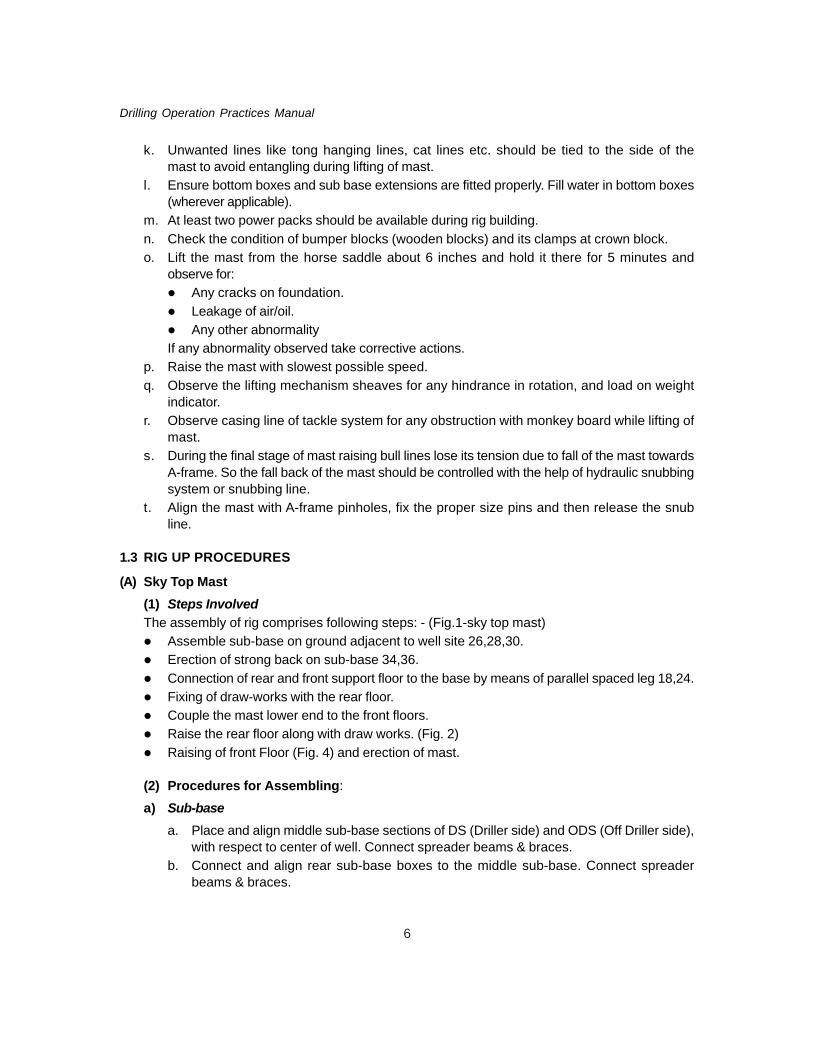
(A) Sky Top Mast(1) Steps InvolvedThe assembly of rig comprises following steps: - (Fig.1-sky top mast)
Assemble sub-base on ground adjacent to well site 26,28,30.Erection of strong back on sub-base 34,36.Connection of rear and front support floor to the base by means of parallel spaced leg 18,24.Fixing of draw-works with the rear floor.Couple the mast lower end to the front floors.Raise the rear floor along with draw works. (Fig. 2)Raising of front Floor (Fig. 4) and erection of mast.
(2) Procedures for Assembling:
a) Sub-basea. Place and align middle sub-base sections of DS (Driller side) and ODS (Off Driller side),
with respect to center of well. Connect spreader beams & braces.b. Connect and align rear sub-base boxes to the middle sub-base. Connect spreader
beams & braces.
7
Land Rig Classification and Rig Building
Fig. 1 : 12-Mast (a, b, c, d, & e are mast section), 14-trailer, 16-Mast pivot, 18-Front support, 22-drawworks Floor , 24-D/works support floor, 26-sub-base, 28-Rear halve of sub base, 30-Front halve of sub-base, 31-sub-bases joining point , 32- Strong back Assembly, 34-vertical column of strong back assembly,36-Digonal support to strong back assembly, 38-Sheave, 40-D/works support floor under structure, 42-Front floor support under structure
Fig. 2 : 80-sheave, 88-Sheave, 104-casing line, 108-T/block hook, 110-direction of block movement, 112-Rear floor raising bull line, 116-Rear floor raising line dead end
c. Connect front sub-base extensions to middle boxes while raising and lowering of mastonly.
NOTE: Front sub-base extensions may be removed for ease of operation.
b) Sub-structurea. Install strong back columns and braces on sub-base in DS and ODS respectively and
connect strong back spreader beam.
80
22
38
116
32
88
104
104106
12
110108112
26
1826
22 34
32 38
36 16
20 12 14
24 40 40 28
26 10
31 42 30 42 18 12a 12b 12c 12d 12e
8
Drilling Operation Practices Manual
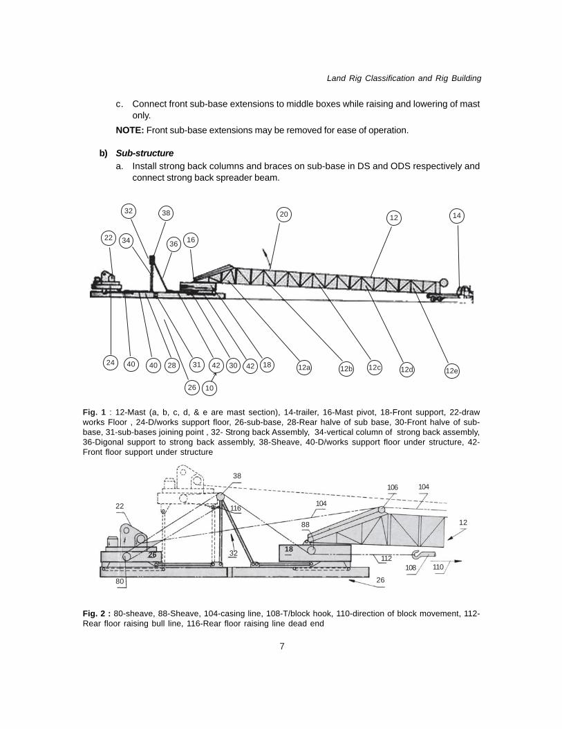
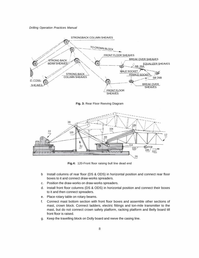
b Install columns of rear floor (DS & ODS) in horizontal position and connect rear floorboxes to it and connect draw-works spreaders.
c. Position the draw-works on draw-works spreaders.d. Install front floor columns (DS & ODS) in horizontal position and connect their boxes
to it and then connect spreaders.e. Place rotary table on rotary beams.f. Connect mast bottom section with front floor boxes and assemble other sections of
mast, crown block. Connect ladders, electric fittings and ton-mile transmitter to themast, but do not connect crown safety platform, racking platform and Belly board tillfront floor is raised.
g. Keep the travelling block on Dolly board and reeve the casing line.
Fig.4: 120-Front floor raising bull line dead end
Fig. 3: Rear Floor Reeving Diagram
STRONGBACK COLUMN SHEAVES
TO CROWN BLOCK
FRONT FLOOR SHEAVESBREAK OVER SHEAVES
STRONG BACKCOLUMN SHEAVES
STRONG BACKBEAM SHEAVES
FRONT FLOORSHEAVES
BREAK OVERSHEAVES
MALE SOCKETFEMALE SOCKET
EQUALIZER SHEAVESSB 26A
SB 26B
22
24
38
120
32 18
88
104
26
114118
106
108 110
12

9
Land Rig Classification and Rig Building
h. Rear floor raising Reeve rear floor raising lines and fast line (d/works) as per Fig. 3and fix dead end connections on both sides. Raise the rear floor along with draw-workswith the self-power of draw-works.
i. Connect rear support box to strong back columns and fit the braces of rear floor boxes(DS & ODS). Connect all other joints with strong back beam.
j. The mast is rested on trailer as per drawing for front floor raising (fig.1).k. Front floor raising Reeve front floor raising lines as per Fig. 5 and fix dead end
connections on both side. Raise the front floor with the self-power of draw-works. Thetrailer must be allowed to follow the motion of mast.
l. After front floor being elevated connect front floor support boxes to strong back. Alsoconnect rotary spreader to strong back beam.
m. Pin column braces of front floor (DS & ODS).n. Ensure all pins are well fitted and all member connections are perfect.o. Reeving for raising the floor
Rear floor erection or lowering.Use the rear floor raising line only, when front floor is down.Use the front floor raising line only, when front floor is up.
Front floor erection or lowering.Use front floor raising line only, in all conditions.
Mast Erectiona. Assemble (or expand if already fitted on mast) A-frame and swing its rear legs, fit it to the
pedestal in rear floor boxes.b. Place the mast on the horse.c. Fix Belly Board, Racking platform (monkey board) and Crown block safety platform with
handrails and other accessories.
TO CROWN BLOCK
FRONT FLOORSHEAVES
BREAK OVER SHEAVES
STRONG BACKSHEAVES
STRONG BACKBEAM SHEAVES
MALE SOCKETFEMALE SOCKET
FRONT FLOOR SHEAVES
DEAD END CONN
BREAK OVERSHEAVES
SB 26C
SB 26D
STRONG BACKSHEAVES
DEAD END CONN
Fig. 5 : Front Floor reeving diagram

10
Drilling Operation Practices Manual
d. Reeve bull lines as per Fig.6.
e. After raising floors pullTravelling Block and Dolly towithin 40’-0" approximatelyfrom the center of well. Usecrane to lift traveling block tothe required height, passbull line through equalizerpulley and connect theirends. Then tighten casingline for keeping TravelingBlock in elevated position.
f. Racking finger and divingboard should be secured tohand railings of monkeyboard.
g. Attach necessary snub-line(in crown block) to protectthe fallback of mast.
h. Slowly raise the mast till itis near to vertical. Here bullline will be slackened, socontrol the mast fall backwith snub line. As the mastpinholes align with A-frameholes, pin up mast to A-frame.
i. Now bull l ine can beremoved.
j. Center the mast beforedrilling, by an 8" drill collarhung from T/ block as a plumb. If required provide adequate shims for centering.(i) Jacking and lowering shall be done on one leg at a time.(ii) No bolts shall be removed from shoes, loosen nuts only. After alignments, tighten the
nuts.Note: Remove front sub-base extension before start of drilling operations.
k. Install all sub-structure accessories, such as adjustable flight stairway, exterior flooring,B.O.P. trolley beams Ramp and stair combination, handrails etc.
(3) Procedure For Rigging Down
Mast Lowering : - (Fig. 7)a. Attach front sub-base extension before lowering the mast.
12
20
66
60
64
6222
5416 18
44
40
48
40
32
3426
36 4258
56
42
52
24
Fig. 6

11
Land Rig Classification and Rig Building
b. Remove all sub-structureaccessories and items addedafter erection of mast, whichmight interfere with lowering ofmast.
c. Reeve Bull line and attach snubline for initial motion of mast.
d. Do not allow any slack on Bullline or fast line before and whilelowering the mast.
e. Guide floating sheave (in A-frame) to align with fast lineduring lowering.
f. Place mast on horse.
Floors Lowering (either thefront or rear floor can belowered first).a. Remove interior and exterior
flooring and doghouse.b. Remove crown block safety
platform, monkey board, andBelly Board then place maston small stand.
c. Disengage bull lines and place T/block on dolly board.d. Rest mast top section on trailer.e. Reeve floor raising line as per the requirement of floor (Prefer front floor. Swing A-frame
on mast).f. Whichever floor is lowered, first remove its column braces, box pins and spreader pins.g. Lower floor cautiously and trailer must be allowed to follow the mast forward movement.
CAUTIONS
(i) No floor raising line slack shall be allowed before or during lowering.(ii) Do not remove any braces or pins of the floor that is not ready for lowering.
(B) Branham Mast
Sequence one (Fig. 8)
(i) Bottom Boxes, Spreaders, Braces and ‘A’ Framesa. Place DS and ODS Bottom Boxes on Center Line using Front and Rear Spreaders and
Braces to ensure that the Bottom Boxes are correctly positioned.b. Pin and Bolt Front Extensions & Rear Extensions to Bottom Boxes.c. The A-Frames are normally transported folded into the Bottom Boxes. Erect A-frame on
sub-base or bottom box.
Fig. 7
600 LBs
C.G. 137600 Lbs73’-3”
8600 LBs
VIEW A-A
APPROX 170’ - 0” TO 200’

12
Drilling Operation Practices Manual
d. The Draw-works Support Braces are normally transported pinned to Bottom Boxes.
Sequence Two (Fig. 8)
(ii) Setback, Mast, Crown, Ladders & Tong Counterweightsa. Position Front Setback Legs on Support Arms on Bottom Box Extensions and Pin to Bottom
Boxes of DS and ODS.b. Position Setback Spreader on Bottom Box Extension Stools, and pin to Front Setback Legs.
Ensure that the top and bottom Setback Leg Pin connections are well greased.c. Pin Front B.O.P. Trolley Beam to Setback Spreader of DS and ODS.d. Pin Mast Bottom sections to Bottom Boxes and Pin to Setback Spreader of DS and ODS.
Ensure that the Top and Bottom Pin connections are well greased.e. Pin Mast stub section Spreader to stub sections after mounting Fast-line Roller on the two
pillow blocks supplied. Check free rotation of roller.f. Place Traveling Block, Hook and equalizer, with Hook approximately 60 ft. from centerline
of Well.g. Assemble Mast lower sections of DS and ODS to lower section Spreader, lift section and
pin to stub section and pin in lower section Braces.h. Place Mast assembly stands (small stand) under lower sections near the top and pack up
as necessary.i. Assemble Mast middle sections of DS and ODS and middle section spreader. Lift section,
pin to lower section, lift slightly to release Mast assembly stands, move stands to the frontof middle section Braces.
j. Attach lines to Tong Buckets and take lines through to the Brackets on the middle section,reeve snatch Block and tie line off at a convenient point on Stub Section.
Fig. 8
Sequence one “A” Frame Erection
C
BA
D

13
Land Rig Classification and Rig Building
k. Assemble Mast upper section of DS and ODS, lift section and pin to middle section, liftslightly to release mast assembly stand and move stand to front of upper section.
l. Normally the Mast top section is transported with the Crown block attached. Lift Crownblock with top section and pin to upper section.
m. Assemble flooring extension, Braces and handrails to Crown Frame. Fit Core line Sheave,etc., to Crown Frame.
n. Fit ladders to DS from Stub Section to Crown.o. Fit Standpipe. Clamps attached with ‘U’ Bolts to the lower and Stub Section of the Mast of
ODS. Check that the Standpipe does not interfere with Setback Spreader when raising theMast. If interference occurs remove Standpipe before Raising the Mast.
p. Lift Mast at Crown with the Crown Pad eyes and place it on (16’0" high stand) horse undertop Section near the Crown Frame.
(iii) Drawworks etc.a. Pin rear draw works Support Columns to Bottom Boxes of DS and ODS and bolt together
with Spreader. Grease pin connections.b. Pin Front draw works Support Column to Bottom Boxes of DS and ODS and bolt together
with Spreader. Grease pin connections.c. Position draw works Support on Bottom Box and rear Extensions and pin to front and rear
support columns. Grease pin connections.d. Pin draw works extension to draw works Support.e. Set draw works and bolt down as recommended by equipment Supplier. Connect air and
Brake water systems, fill water tanks in bottom boxes of DS and ODS.f. Pin Rotary Support Beam Unit and Rotary Floor Support Units.g. Fit draw works flooring & Wing Flooring.
(iv) Mast Reeving, Racking Board, Mast Raising and Snubbing(Place Traveling Block, Hook and Equalizer at approximately 60 ft. from the centerline of wellbefore assembling the Mast Lower Section to the Mast Stub Section.)a. Before reeving, lubricate all Sheaves and ensure they rotate freely. Using the longest bull
line connect open socket to bull line Anchor on Mast section and pass line over A-FrameSheave, replace rear line guard roller, pass under vertical Sheave round horizontal Sheaveon Stub section replacing both line guards then take bull line through equalizer (To fit bullline to equalizer it will be necessary to remove Sheave and shaft from the yoke). Place bullline between Side plates and then slide Sheave back into position replacing Shaft andsecuring bolt.
Using shortest bull line connect open socket to bull line Anchor on Lower Section, then reeveas above connecting Open and Closed Socket together. Special care must be taken whenuncoiling bull line, kink should not come in lines.b. Hook up weight indicator.c. Reeve casing line into tackle system with the help of wire rope, and fasten fast end to
draw works drum.d. Place equalizer on Hook.

14
Drilling Operation Practices Manual
e. Before Raising the Mast: -Check that the Bottom Section and Setback Legs pin connections are well greased.Check that all bolts have been tightened.Check that all pins have been fitted with Safety clips.Check that all line guards have been fitted correctly. Check that all loose tools etc.have been removed from Mast and Crown.Check that all the Line and bull line has been reeved correctly.
f. Hook up BOP chain hoists of DS & ODS.g. Assemble monkey board and skid under Mast, lift the monkey board and pin it to Mast
Middle sections at selected height for operating position. Pin support Brace to Mast middlesection, swing and tie back Diving Board to handrails and open gates at Drill Collar fingersto the maximum.
h. Connect Hydraulic Supply to ‘Quick connect’ Lines on A-Frames of DS and ODS. TestCylinders to ensure that both Rams move simultaneously in the same direction. Fully extendRams ready for Mast Snubbing.
i. Lift the mast from the horse saddle about 6 inches and hold it there for 5 minutes andobserve for:
Any cracks on foundation.Leakage of air/oil.Any other abnormalityIf any abnormality observed take corrective actions.
j. Raise Mast slowly using draw works power until Mast touches Snubbing Noses of DS andODS. Using the Control Unit retract Rams and Continue to Spool in slowly with draw works.During this operation the Mast will ‘Break over’ its center of gravity. Continue retracting
Reeving Diagram For 142’ MAST
Fig. 9
Single Line
Single Anchor
“A” Frame
“A” Frame
To Draw works
238∅ x 144’ SLING LINE (EIPS - IWRC)
238∅ x 164’ SLING LINE (EIPS - IWRC)

15
Land Rig Classification and Rig Building
Rams, while taking up slack with Hook until pin connections line up. Pin the mast with A-Frame on both sides. (Fig. 10)
k. Attach Ramp to Setback Support.
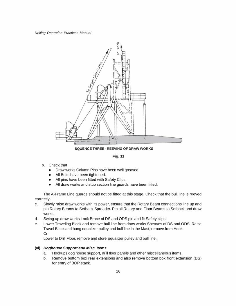
Sequence Three (Fig. 11)
(v) Drawworks Raisinga. Remove rear Line Guard on A-Frame Sheaves, partly Lower Traveling Block, Change bull
line DS and ODS from round to over top of A-Frame Sheave, using soft line from Catheadspull Loop in bull line behind A-Frame while continuing to lower Travelling Block, pass bullline over draw works Sheave of DS and ODS. Replace Line Guards and Take up Slackwith Hook.
Fig. 10
16
Drilling Operation Practices Manual
b. Check thatDraw works Column Pins have been well greasedAll Bolts have been tightened.All pins have been fitted with Safety Clips.All draw works and stub section line guards have been fitted.
The A-Frame Line guards should not be fitted at this stage. Check that the bull line is reevedcorrectly.c. Slowly raise draw works with its power, ensure that the Rotary Beam connections line up and
pin Rotary Beams to Setback Spreader. Pin all Rotary and Floor Beams to Setback and drawworks.
d. Swing up draw works Lock Brace of DS and ODS pin and fit Safety clips.e. Lower Traveling Block and remove bull line from draw works Sheaves of DS and ODS. Raise
Travel Block and hang equalizer pulley and bull line in the Mast, remove from Hook.OrLower to Drill Floor, remove and store Equalizer pulley and bull line.
(vi) Doghouse Support and Misc. Itemsa. Hookups dog house support, drill floor panels and other miscellaneous items.b. Remove bottom box rear extensions and also remove bottom box front extension (DS)
for entry of BOP stack.
To B
lock
To S
ingl
e Li
ne A
ncho
r
Fig. 11
SQUENCE THREE - REEVING OF DRAW WORKS

17
Land Rig Classification and Rig Building
c. Center the mast before drilling, by an 8" drill collar hung from T/ block as a plumb. Ifrequired provide adequate shims for centering.(i) Jacking and lowering shall be done on one leg at a time.(ii) No bolts shall be removed from shoes, loosen nuts only. After alignment, tighten
the nuts.
(vii) Lowering Sequencea. The Lowering Sequence is the reverse of the Raising Sequence. The main sequence is
as below.b. Remove any additional items added after Erection, which might interfere with the Lowering
procedure.c. Reverse Section F.d. IMPORTANT Remove rear B.O.P. Trolley Beams, Hoists and Trolleys. Re-hook Equalizer
pulley with bull line, Reeve bull lines as Section E, making sure that the bull lines passover the A-Frames Sheaves of DS and ODS, and round draw works Support Sheaves ofDS and ODS and sockets are correctly pinned to Lower section Mast of DS and ODS.Replace Line Guards at Stub and draw works Sheaves. Tighten block and checkLines.
e. Unpin and lower draw works Lock Brace.f. Unpin Rotary Beam Unit at draw works only.g. Unpin Rotary Floor Beams at Setback only.h. Cautiously lower the draw works.i. Connect Hydraulic’ Power to snubbing unit of DS and ODS.j. IMPORTANT Change Bull line of DS and ODS as shown on section D. Make sure the
bull lines are round A-Frame Sheaves of DS and ODS.k. Replace Line Guards.l. Tighten block and recheck bull lines.m. To lower Mast remove pins and extend Rams of snubbing unit while lowering the Hook,
maintaining very little slack as Mast ‘breaks over’ its Center of Gravity, continue to lowermast onto Mast horse. Continue section D to A in reverse order for further de-rigging.
SLING (BULL) LINE INSPECTION AND REPLACEMENT
There are three factors, which may limit the life of sling line.(1) Wear due to operation: it is a function of the number of times the mast is raised.(2) Corrosion: It is related to time and atmospheric conditions.(3) Incidental damage: It may occur at first location or any other location.Points to be kept in mind for inspection & replacement of sling lines:a. Data used for replacement does not give any clue. Because some times line are replaced
early due to incidental damage and some times lines are used beyond the time whenthey should be replaced.
b. There is no way of judging the remaining strength of a rusty rope, so it should bereplaced. Especially areas adjacent to end connections should be examined closely forany corrosion. In coastal areas sling lines left hanging in the mast may becomecorroded and found unfit for further use.
18
Drilling Operation Practices Manual
c. It is possible to establish sling line life expectancy in terms of number of locations onwhich it was used, as long as a set number of months were not exceeded. But againthis will not preclude the necessity of careful inspection. A line showing with broken wiresshould be replaced. A line with any material reduction of metal from abrasion should bereplaced. A line showing kinking, crushing, or any other damage resulting in distortion ofrope structure should be replaced.
d. Replacement of lines based on normal life expectancy will provide some degree of safety,but due to which there should not be any laxity in sling line inspection.
e. Sling line should be maintained in a well-lubricated condition. The field lubricant shouldbe compatible with the original lubricant. The object of rope lubrication is to reduce internalfriction and prevent corrosion.

19
Land Rig Classification and Rig Building
Annexure-1
RIG BUILDING PLANBHEL Electrical Rig / Sky Top/ Brahnam : Day wise activities and requirement of fleet:
Job to be done Crane Days TrailerLoad
D1 Cleaning front side of mast, dismantling of mud Type 1 (OS) 1 14system/mud pumps, two power packs, and one Type 2 (OS) 2diesel tank/water tank/hopper.Loads: Type 2 (NS) 1Power pack – 2Diesel tank – 1Water tank – 3Water tank Skid –1Hoppers skid – 1Reserve tank – 4BOP Control – 1Trip Tank -1
D2 Lowering of Mast, substructure, dismantling ofmastTPT: Type 1 (OS) 1 17Mud pumps – 2 Type 2 (OS) 2Power Pack – 2 Type 2 (NS) 2Diesel tank – 1Utility (Compressor) house – 1Mud tank –3Super charger with skid – 1Degas/D. silt. Pump – 1Mast & structure – 4Monkey Board – 1Belly board - 1
D3 Dismantling of mast & substructureTPT: Type 1 (OS) 1 14Mast section – 5 Type 2 (OS) 2Set back – 1 Type 2 (NS) 2Draw works – 1Draw works platform – 1Bottom Boxes – 2Tubular – 2Other loads like desander, desilter, Shale shaker - 1T/Block etc. - 1
D4 Assembling of substructure and mast.Continue assembly of mud system Type 2 (OS) 2 9TPT:Cat walk – 1 Type 1 (NS) 1Dog House – 1 Type 2 (NS) 2HP Line – 1Mast & substructure left over items – 1Mech./ Elect. Bunk Houses –2Store Rooms - 3

20
Drilling Operation Practices Manual
D5 Assembling of mast completed & casingline reeving and assembly of mud system. Type 1 (OS) 1 6TPT: Type 2 (OS) 1DIC Bunk house – 1 Type 2 (NS) 3Staff Bunk House – 1PCR – 2BOP, Choke & Kill assembly and other leftover Tubular -2
D6 Lift mast on horse & fix Monkey Board,belly board. Mud system to be completed Type 2 (OS) 1 6TPT: Type 1 (NS) 1Complete transportation from old site Type 2 (NS) 2
D7 Checking of power and raise the mast, fixing Type 2 (OS) 1of d/floors, HP lines, removal of bull lines. Type 1 (NS) 1Fitting of cat walk/ inclined ramp, pipe rack Type 2 (NS) 2dog house.
D8 Preparation of spudding Type 2(NS) 1
Abbreviations:- OS – Old site, NS – New Site,
Note: -1. Rig movement is within the radius of 20 Km. during good weather condition.2. Rig equipment should be transported on above priority so that it is unloaded at appropriate
place at new site.3. For sky top mast one more day is required due to its design.4. Type 1 crane capacity – 75 Ton , Type 2 crane capacity – 30-40 Ton5. Also 1 Truck is needed for miscellaneous items as per the requirement of rig In-charge.
Job to be done Crane Days TrailerLoad

21
Land Rig Classification and Rig Building
Annexure-2SIZES OF DIFFERENT LIFTING LINESSKY TOP MAST
SN Type of Rig Type of Line Description Remarks
1. E -760 Bull Line (i) 1 ¾” Φ, 6 × 37 classification, 6x49 Both Open endconstruction, IWRC,EIPS, RHRL 127’-6"
Floor Lifting (ii) 1 ¾” Φ, 6 × 37 classification, 6x49 One open end &Line construction, IWRC, One closed end
EIPS, RHRL 147’-6"(iii) 1 1/8" Φ, 6 × 37 classification, 6x49 One open end &
construction, IWRC, One closed endEIPS, RHRL 142’
(iv) 1 1/8" Φ, 6 × 37 classification, 6x49construction, IWRC, EIPS, RHRL 163’ Both open end
(v) 1 1/8" Φ, 6 × 37 classification, 6x49construction, IWRC, EIPS, RHRL 90’ Both open end
2. E-2000 Bull Line (i) 2" Φ, 6 × 37 classification, 6x49 Both open endconstruction, IWRC, EIPS, RHRL 126’
Floor Lifting (ii) 2" Φ, 6 × 37 classification, 6x49 One open end &Line construction, IWRC, EIPS, RHRL 150’ One closed end
(iii) 1 1/8" Φ, 6 × 37 classification, 6x49 One open end &construction, IWRC, EIPS, RHRL 142’ One closed end
(iv) 1 1/8" Φ, 6 × 37 classification, 6x49 Both open endconstruction, IWRC, EIPS, RHRL 163’
(v) 1 1/8" Φ, 6 × 37 classification, 6x49 Both open endconstruction, IWRC, EIPS, RHRL 90’
Snub Line ½” Φ, 6 × 37 classification, 6x49construction, IWRC, EIPS,
For Front Floor Use – (iii) + (v)For Rear Floor Use – (iii) + (iv)
BRANHAM MAST
SN Type of rig Type of Line Description Remarks
1. E-760 Bull Line (i) 2 3/8" Φ, 6 × 37 classification, 6x49 One Open socket &construction, IWRC, IPS, RHRL, 145’ One closed socket.
(ii) 2 3/8" Φ, 6 × 37 classification, 6 × 49 Both Open endclassification, IWRC, IPS, RHRL, 135’ socket
2. E-1400 Bull Line (i) 2 3/8" Φ, 6 × 37 classification, 6x49 One Open socket &construction, IWRC, IPS, RHRL,164’ One closed socket
(ii) 2 3/8" Φ, 6 × 37 classification, 6x49 Both Open endconstruction, IWRC, IPS, RHRL, 144’ socket
3. E-2000 Bull Line (i) 2 3/8" Φ, 6 × 37 classification, 6x49 One Open socket &construction, IWRC, IPS, RHRL, 194’ One closed socket
(ii) 2 3/8" Φ, 6 × 37 classification, 6x49 Both Open endconstruction, IWRC, IPS, RHRL, 175’ socket

22
Drilling Operation Practices Manual
CHAPTER- 2OFFSHORE RIG
Independent-leg units and mat-type units are designed to withstand certain operating limits for(1) load capacities (2) afloat conditions and (3) elevated conditions. Any attempt to exceed theselimits will jeopardize the safety of the crew and the unit. Jacking and moving procedures must takeinto account the capabilities and limitations of the unit when sitting on bottom, when afloat, or undertow. All personnel operating the unit’s equipment should read the “Information and OperatingInstruction Book” published by the manufacturer. This book gives specific instruction on the operationand maintenance of the unit’s machinery.
Newly classed ABS jack up rigs have emergency power sources. Check the emergency powerplant and all emergency systems at least once a week. Emergency repair supplies should be onboard, and be inspected periodically for quantity and condition.
2.1 PERSON ON BOARD: Recommended Nos. & type of persons to jack down and move drillingunits are:
NUMBER POSITION/LEVEL TASK DESCRIPTION
1 Move Supervisor In charge of operation
1 Tool pusher Assigns individual responsibilities; is jacking console operator
1 Driller Maintains proper clearances and communication with consoleoperator
1 Rig Engineer Assigns Electrician, Mechanic, and Motorman responsibilitiesand stands by to assist
1 Electrician Stands by below deck to take action to correct any electricalmalfunction
1 Mechanic Stands by below deck to take action to correct any mechanicalmalfunction
1 Welder Assures that welding equipment is in good condition and thatwelding supplies are on board
1 Derrick man
2 MotormanThree men assigned to each yoke house
6 Roughnecks orRoustabouts
2.2 JACKING DOWN OPERATION
1. Switch fixed pins to “OUT” on all columns.
2. Lower yokes (raise platform) slightly with master jacking lever, monitoring rod end pressuregauges and “FIXED PIN OUT” light on all columns. If rod end pressure reaches 2500 psi oncolumns 1, 2, or 3 before the red “FIXED PIN OUT” light on any of those columns comes

23
Offshore Rig
on, stop jacking until the fixed pin (or pins) which may be stuck is disengaged. Confirmationof the pin situation from each column should be obtained with every pin change beforeproceeding with the jack-ing. This information should be obtained by telephone from personnelin each jack house.
3. When all fixed pins are confirmed to be “OUT,” use the master jacking lever to raise theyokes (lower the platform) in unison one full, six-foot stroke. During the stroke, the aluminumwedges can be removed.
NOTE : The automatic leveling device incorporated within the jacking system should keepthe three yokes in line to: 1 inch relative to column 1 during the power stroke. During thepower stroke and when about 10 inches from the end of the stroke, switch all the fixedpins to the “IN” position on the console and continue jacking in the same direction. Thesepins will not move all the way in immediately as they are not centered over the respectivepin holes, but the “FIXED PIN OUT” lights will go off and the pins will be loaded up againstthe columns ready to go into the column pin holes as soon as they become aligned. Asthe end of the stroke nears, watch both the “FIXED PIN IN” lights and the rod-end pressuregauges for all three columns. The green “FIXED PIN IN” lights, indicating that all fixed pinsare in, should come on before rod end pressure starts to decrease. If there is an indicationof pressure decrease before a green light activates on any one column, jacking should bestopped until the cause of the problem can be determined (such as a stuck fixed pin, amaladjusted limit switch, etc.).
4. When all fixed pins are “IN” and confirmed, switch yoke pins to “OUT” position on the console,and use the master jacking lever to raise the yokes (transfer the platform load to the fixedpins), allowing the yoke pins to disengage themselves from the columns. Confirm yoke pindisengagement and then push the master jacking lever to the “YOKES DOWN” position forthe return stroke (six feet). Switch yoke pins back to the “IN” position, again, about sixinches before the end of the return stroke, and continue jacking until all yoke pins are “IN”as before and confirmed.
5. Repeat steps 2, 3, and 4 as required to bring the platform down to the water. Before theplatform enters the water, a platform weight summary and platform longitudinal center ofgravity (LCG) calculations are to be made. This is required for determining the amount ofdrilling water to be shifted in the platform in order to obtain even keel conditions when themat is free and the unit floating. The method for adjusting the platform LCG to coincidewith the floating longitudinal center of buoyancy (LCB) will normally be by shifting drillingwater only. If feasible for the particular drilling unit and location, the derrick skid unit mayalso be moved to expedite the adjusting of the LCG. Continue jacking down until platformdraft exceeds the calculated floating draft by two feet. With this amount of excess buoyancy,the mat should free itself from the sea bottom, as can be observed by a decrease in platformdraft and head end pressure on all three columns. If difficulty is encountered and the matwill not pull loose with two feet excess draft, provisions have been made for water to bejetted from the underside of the mat. The piping for this system terminates in column 1.
6. Using the same action it took to lower the platform, raise the mat the desired clearance(bottom to bottom) for the move. If it is desired to raise the mat up to the uppermost position(2’6" clearance between the molded platform bottom and mat deck), override the automaticshutdown at columns 2 and 3. This is accomplished by holding the override button down inthe lower left corner of the console before the end of the last 4’6" stroke is reached.
24
Drilling Operation Practices Manual
7. When sufficient clearance between the bottom of the mat and sea bottom exists, pressureup the rod ends of all cylinders (lower the yokes) with both the fixed pins and the yokepins engaged and the yoke down to about 1500 psi. This will prevent relative movementbetween mat and platform due to wave action. If after a period of time the pressure decreasesin the rod end of the cylinders, they can be repressured to 1500 psi.
GENERAL NOTES FOR SERVICE AFLOAT
1. All sounding tubes must be capped except, and only, when in actual use.
2. Manhole covers into the inner bottom tanks must be bolted closed at all times unlessaccess to a tank is necessary. Immediately upon completion of each job requiring accessto any tank, the manhole cover must again be bolted closed.
3. While the unit is afloat, all manifold valves and all bilge control valves in the tank pipingsystems must be closed unless, and only when, they are necessary for system operation.Also, all plugs, caps, etc., at filling points must be closed.
4. All watertight hatches, vents, and companionways must be secured watertight while theunit is afloat except when in actual use.
5. All watertight doors and thru-bulkhead vents are to be closed.
6. The preload dump valves must be closed at all times, both afloat and elevated, except duringthe actual discharge (dumping) of the preload.
2.3 RIG MOVE AND PRELOADINGPreparation for drilling the next well should be carried out while the rig is moving between
wells or locations. Rig movement and deck-loading conditions may determine the scope ofwork that can be carried out during rig move and positioning operations.
2.3.1 Procedure
Conduct the shallow gas survey1. Perform fluid end inspections on the mud pumps and change liners as specified in the well
programme.
2. Reset relief valves (pop offs) of the mud pumps depending on the liner burst rating as requiredfor the liner in use, settings are specified in the manufacturers recommendations (pressuretest to be recorded on a chart).
3. Perform inspections of all BOP equipment e.g. BOPs, safety valves etc. If possible pressuretest these items with water.
4. Service all standpipes, valves, chick sans, hoses, choke and kill manifold valves, and conductpressure test of these if required.
5. Service / inspect all tensioning and BOP handling equipment e.g. conductor pipe or BOPtensioners.
6. All mud handling equipment should be serviced including, shale shakers, mud cleaner,desander, desilter and mud mixing equipment. The shale shakers should be fitted with thecorrect size of screen for the top-hole section as per requirement.
7. Check the calibration and function of all drilling instrumentation e.g. gauges, chart records.

25
Offshore Rig
2.3.2 Skid Cantilever and Rig Up
Once the rig has been pre-loaded and jacked up to the final air gap, as per the operationsmanual, and permissions obtained from the OIM, drilling operations may commence. The first ofwhich is to skid the cantilever and drilling package out to the desired operating position.
During skidding operations position watchmen to ensure that the skid beams / package doesnot contact any of the installations/ fixed equipment. Service hoses, electrical loops and cable trayswill also be monitored to prevent damage to them.
1. Once skidding of cantilever and drilling package is complete check that rotary table ispositioned directly over the proposed well centre. .
2. Secure the cantilever and drilling package to prevent any movement during the well.
3. Install any drill floor access stairs, walkways and v-door ramp if removed for skidding. Installany safety equipment (handrails) and adjust / install mud return flow line.
2.4 SURFACE HOLE PREPARATIONThis phase of the process ensures that the rig is fully operational prior to the actual spudding
of the well. It also verifies that all equipment and materials required for the surface hole section areon board, certified and in good working order.
2.4.1 Procedure1. A Rig Specific Procedure for handling the Master Bushings during drilling, running surface
casing, BOP and diverter operations be in place and followed.
2. When rigging up to run 30" and 20" casing, the bushings not be removed until the shoejoint is ready to be run through the rotary table.
3. A hole cover be in place when ongoing activities, associated with the removal andreplacement of rotary table components, are suspended for any period of time.
4. A pre-spud meeting be held with all personnel involved in the operation. Minutes of thesemeetings be DOCUMENTED.
5. Ensure that all the relevant fishing equipments are available.
6. Consult with the Client and service personnel to verify the wellhead systems and stack updimensions.
7. Specified quantities of mud chemicals, including barite and bentonite, should be on location.
8. Sufficient spud mud, with the correct properties as specified in the drilling programme, shouldbe mixed ready for use.
9. Specified quantities of cement and additives should be on location.
10. Drilling consumables for the first hole sections should be on location including but not
limited to wellheads, casing and its handling tools, drill bits and nozzles of various sizesstabilizers, hole openers and reamers.
11. All drilling tools supplied by the Client should be checked for compatibility with theContractors equipment (e.g. correct tool joint connections). This should include both drillingand fishing tools.
12. Prepare the BHA, pick up, drift and rack enough drill pipe to complete the surface holesections. Making up and racking stands during drilling operations is not permitted.
26
Drilling Operation Practices Manual
13. Measure the conductor pipe (measurements to be checked by clients representative) todetermine the correct footage of hole to be drilled.
14. Check all conductor handling equipment for certification and compatibility with the size ofcasing to be run.
15. If casing is to be run using lifting eyes then check the slings shackles are available andare certified to the appropriate load rating.
16. Check that there is sufficient oxygen and acetylene equipment ready to cut the lifting eyes.
2.5 CONDUCTOR PILING (DRIVING)Conductor, drive pipe or structural pipe are all terms used to describe the first string of casing
to be set. Sizes of casing vary depending on the Clients requirements and well plan. The casingsize referred to in this section is 30" as it is the most common; however specific requirements willbe issued in the well programmed. Initially it will allow a circulation system to be set up takingreturns back to rig. It allows the diverter system to be hooked up. It also prevents surface sedimentsfrom sloughing and protects against rig foundation failure (washout). The 30" may be driven(hammered) from the seabed to a desired depth / refusal or to a pre-determined blow per foot count.
2.5.1 Procedures1. Check the derrick, top drive, block, and crown prior to and after the hammering operations
for any loose objects.2. Paint the shoe joint white to assist with ROV observation.3. Run the 30" casing to one joint above the seabed then rig up the hammer and chaser joint.4. If available the ROV will observe seabed for obstructions prior to the 30" penetration.5. All lifting gear on the hammer assembly will be checked for rating and certification. All
shackles will be secured with split pins and checked periodically during the operation.6. To ensure the 30" is vertical, tag the seabed and commence driving at slack tide. Record
the rotary to seabed measurement and weight of 30" from rotary to seabed in the IADCdrilling report. Once maximum bottom penetration is achieved from the weight of the 30"alone, allow the hammer and chaser joint to rest in the top of the 30".
7. Do not allow the hammer support slings to take load while driving, continue to watch themand slack off on the blocks simultaneously.
8. Ensure that hammer operator is also monitoring the support slings, is situated next to thecontrols and is able to stop the hammer blows should the need arise.
9. Do not set slips on the 30" once driving has commenced.10. Should the desired shoe depth not be obtained before a pre-determined maximum blow
count per foot of penetration or refusal, then it may be necessary to implement a drive /drill procedure.
2.5.2 Drive / drill procedure.1. Rig down and layout the hammer then run in with a 26" bit and BHA.2. Support the weight of the 30" while drilling using the conductor tensioning/support system.
This may require the use of 30" elevators, pad eyes or a load ring on the 30".3. While drilling limit the ROP to prevent overloading of the annulus and do not drill further
than the shoe.

27
Offshore Rig
4. The 30" will not be driven if shallow gas is a potential problem unless the formations havebeen drilled and proven to be gas free.
2.6 FLOATERSFloaters are the drilling vessels that keep floating during the entire course of drilling and other
operations. In off-shore, drilling is much economical with jack-up rigs but their limited water depthcapability (generally 400 ft.) is a major handicap as we venture in deep waters. On the other hand,floaters, if equipped with dynamic positioning system are independent of water depth and seabedconditions. Also in the water depth range of jack-ups floaters also provide a solution to some problemslike punch through locations. However, the initial investment and the operating cost of floaters aremuch higher than that of a jack-up rig.
i) DrillshipDrill ships are suitable for water depths 20m-3000m plus. Drill ships are suitable for drilling indeeper waters beyond the limit of Jack-ups. Also, they can be deployed on a location wherejack-up operations is not possible due to soft/loose seabed having a gradient more than thethat required for Mat type jack-up.
They are suited in logistically difficult areas as normally they have high load carrying capacities.However, anchor moored type ships are not suitable for harsh environments as their responseto hydrodynamic forces is not as good as compared to Semis. Therefore in harsh weathers,downtime tends to be much more on a drill ship than a Semi. Otherwise, drill ships are morestable in terms of survival and station-keeping in adverse weather conditions as their CG islower. The variable loads like casings, risers, tubulars, mud chemicals etc. are stored on a drillship at much lower level as compared to a Semi. This keeps the CG at much lower level andimparts more stability to drillships. Drillships are normally cheaper than semi-submersibles formoderate environment areas. They can carry out exploratory drilling, development drilling onsubsea templates and subsea completion of single wells.
ii) Semi-submersibles or Column Stabilised RigThese rigs are floater type rigs in which the drilling deck is mounted on columns which aresupported by submerged pontoons or hulls. Around half the length of columns is also submergedin water. Semis can be triangular, rectangular or pentagonal type. The most popular is rectangulardesign in which there are two bottom hulls each supporting 3 to 4 columns on which workingdeck is placed. They are suitable for water depths from 30m - 2500m.
They are more suitable in areas with rough sea conditions and harsh environ-ments includingicy seas. They are designed to minimise the impact of hydrodynamic forces on the vessel thusgreatly reducing the heave as well as roll and pitch. The pontoons are much below the surfaceof water and drilling deck is raised high up, keeping only the columns in contact with wave/swell action. This way, its response to hydrodynamic forces is excellent. But they are moreprone to capsizing as the centre of gravity keeps on moving up with the addition of load on topdeck during drilling operations which is inevitable. This reduces meta- centric height and thusthe righting lever & tendency to capsize increases.
This results in a drastically reduced deck load capacity as compared to a drillship. Semis arecostly in operations but are a better choice for areas where harsh weather prevails for a longerperiod during the year.

28
Drilling Operation Practices Manual
2.7 STATION KEEPING
A. ANCHOR MOORED : 8, 9 or 10-point mooring, Self Propelled. Suitable for water depth upto1500m. New ships are being designed which will be capable of anchor mooring in approx.2400m of water depths. Turret moored rig are capable of reorienting themselves as perweather conditions using its turret and thrusters.
B. DYNAMICALLY POSITIONED : Station keeping is done by DP system though anchorsare also normally provided. They are self propelled and are suitable for areas with waterdepths greater than 1500m, or lower water depths with harsher environments or locationswhich may require quick movement like frequent storms, or places with subsea pipelines,communication lines etc. They are very costly to operate as fuel consumption is very highfor DP system.
2.8 DIFFERENCE BETWEEN FLOATER AND JACK UP RIGS
FLOATER
Vessel keeps floating during the entire courseof operations and is subjected to variousmovements like Roll, Pitch, Heave etc. whichimpede operations.
30" casing is lowered in a drilled 36" hole withseawater with no returns to the rig.
26" hole is also drilled (generally) with seawaterwith no returns to the rig.
Every casing string lowered in the well isterminated at the seabed (except liner casing).
BOP stack (generally 18 ¾” bore) is loweredand installed at the seabed after 20" casing andonce installed all the subsequent operationsright up to abandoning of the well are carriedthrough the stack .It has more functions andrequires special handling system.
A string of risers about 20" bore is used whichneeds a special tensioning system to maintainconstant tension for heave compensation. .
BOP control system is much more complex forremote operation and redundancy.
Drill String Motion Compensator is used tomaintain WOB
JACK-UP
Once the vessel is jacked-up it stands firmlyon the ocean floor like a fixed platform.
30" casing is piled in to the seabed.
26" hole is drilled with seawater/mud and returnsto rig.
Every casing string lowered in the well isbrought up to the surface (except liner casing).
The BOP stack (generally 13 5/8") has to beremoved for the installation of each section ofwell head. Dimensionally this stack is muchsmaller in size and has less no. of rams,annulars and Kill/chocke line valves.
A single riser pipe is used.
BOP control system is same as that is usedon land rigs.
Not required

29
Offshore Rig
2.9 SEQUENCE OF DRILLING A WELL FROM A FLOATER:• Once a location is released for the deployment of a floater, the site is surveyed and a marker
buoy is dropped by the survey boat on the location for easy identification (In shallow waterdepth).
• The vessel moves to the new location.• The vessel moves into position and the heading is adjusted depending on the prevailing
sea condition.• The running of anchors begin with the help of anchor handling vessel. The anchors are laid
as per a predetermined pattern, pre-tensioned and then slacked-off to the operating tensionvalues. or
• If the vessel is equipped with dynamic positioning system, the same is switched on tomove into the position.
• Final adjustment of heading and position is now made with the help of instrumentation.• The vessel is now ready to spud the well.• A temporary guide base is lowered to the seabed during the low tide with the help of
guidelines.• The 36" hole is drilled 80 to 200 ft. below the mud line and 30" casing is run and cemented
in place. During these operations there are no returns of circulating fluid to the rig. Thiscasing is strictly for the structural support and will not sustain any pressures. A permanentguide frame is secured with 30" casing head while running casing to guide the BOP stackon the well head.
• 26" hole is drilled for a 20" casing that is set about 1000 ft. below the mud line. Risers witha pin connector (without BOP stack) might be run with the diverter on top if shallow gassands are likely to be encountered.. The diverter is required because the well can not beshut in on the 30" casing. In this case a pilot hole is drilled and then enlarged to 26"
• 20" casing is run with 18 ¾” well head on top with a running tool and drill pipes. The casingis cemented in place
• The 18 ¾” BOP stack is now run and latched on to the 18 ¾” well head.• The subsequent operations for drilling 13 3/8",9 5/8", 7" phases and the well testing are
carried through the BOP stack• After testing, the well is often plugged and abandoned by squeezing cement into the
perforations used for testing and spotting the cement at given intervals in the casing asthe drill string is pulled out from the well.
• The riser and the BOP stack are retrieved.• The well head equipment including the TGB and the PGB is retrieved by cutting the casing
about 10 ft. below the well head Either explosives or mechanical cutters may be used.• The process of pulling of anchors begins for an anchor-moored vessel while a D.P. vessel
moves to the next location instantly.
2.9.1 Pre-spud Activities
Once anchors are laid and pre tensioned to require load in case of moored rigs or positioningof DP rigs at desired location, penetration test and exploration test to confirm shallow gas presenceis carried out 50-200m down stream of released location as detailed below:

30
Drilling Operation Practices Manual
i) Penetration TestIt is carried out to check the seabed formation to ascertain the depth of conductor casing sothat it can safely withstand the weight of wellhead, subsequent casing and BOP. It is carriedout using a jetting assembly which consist of 12 ¼” bit, bit sub, 3 stands of 8" drill collars,cross over, 5 to 7 stands of HWDP and 5" D/P. The sequence of operations in carrying outpenetration test is as under:1. Bit and bit sub should be painted white for observation by ROV. Space out should be adjusted
so as maintain jetting assembly and bit in the hole while making first connection.2. Gently tag seabed-using ROV and calculate KB to seabed depth with tide correction. Open
drill string motion compensator to full stroke and set pressure to compensate at 5000 Kgs.Lower drill string until the bit is lost from view. This depth is known as murk line.
3. Continue to lower the drill string until the bit takes 5000 Kgs of weight and does not settleany more. This depth is known as competent mud line.
4. Initial WOB and flow rate should be low and be gradually raised one at a time when thereis no progress. Seabed should be tagged at 5-10 spm and 4-6 KIPS of WOB.
5. Penetration test should be continued without rotation up to the point of refusal. The point ofrefusal is the point where the formation can withstand 10 T of slack off.
6. Rate of penetration will be dependent on pump strokes mainly. Initial jetting starts with 20SPM. Keeping parameters same gives a fairly god idea as to when formation begins tochange.
7. Plot a graph Depth vs. time & ROP.8. Based on depth up to the point of refusal conductor casing tally is made.
ii) Exploration TestExploration test to confirm shallow gas presence when the drill string is positioned for jettingtest off location is also conducted there. It is carried out 50 –200m down stream and downwind side so that if gas is encountered ship can be pulled upstream by anchors or usingpropulsion to move away from gas zone. Gas plume in shallow gas occurrences has beenobserved to form a low angle of 10° at the wellhead. Based on this and wind direction locationof this exploration test is decided. The exploration test must be carried out upto the sectionaltarget depth of 26" phase.
Normally shallow gas pockets are observed from 600 to 900m below seabed. Hence Pilot holeshould be drilled upto expected shallow gas/water zone or upto a suitable depth where formationstrength is sufficient to withstand increased mud wt. requirement. Prediction of shallow gasby means of geo technical tools is not very reliable therefore, it is a standard practice to drillsmall size preferably 8 ½” pilot hole. The requirement and procedure for drilling pilot hole forexploration test is as under:
Requirement• A float valve should be installed in bit sub.• As usual a Kelly cock should also be used to arrest gas flow in the pipe.• A minimum of twice the pilot hole capacity of kill mud (10 ppg) should be kept ready.• 50 bbls barite plug to be kept ready.• Cementing unit should be kept in readiness.

31
Offshore Rig
• Captain and marine crew be kept ready for moving rig off location if situation arises.• ROV should be stationed near the seabed.
Procedure• Normal drilling over this section will be relatively fast hence drilling should be done at a
moderate rate so that minor gas flows if any can be identified with ROV.• Always observe the well carefully for gas flow prior to making connection.• If minor gas shows are seen the bit is to be pulled off bottom and observe the well.• If the gas stream continues at a constant rate or diminishes during the flow check then a
further 3m can be drilled, circulate bottom up and observe the well. This procedure tobecontinued till such time that the gas streams is minimal.
• Once safe conditions have been established continue drilling to T.D.• If however the gas flow increases and develops into major flow then the following procedures
need to be followed.• Once a major flow has been noted by the ROV maintain circulation through out the gas
flow kill operation.• Displace hole volume with 10 ppg kill mud.• Inform captain/chief engineer/DP operator.• If the gas stream does not diminish then pump 50 bbl barite plug at bottom.• If the well is dead or subdued then proceed as with a minor gas flow, reaching to bottom
(TD) in 3m interval (prior to that ensure adequate kill mud is made available) or once thewell is under control then pump a cement plug above the barite pill and pull back to seabed to review options.
• If failed to subdue the gas flow with barite plug then prepare to pull rig off location.
Moving Rig off LocationThe gas plume in shallow gas occurrences has been observed to form a low angle (10-degree)
to the vertical. In 900m of water depth the gas plume will be approximately 158m wide. In suchcondition immediate action is to be taken to move the ship off the location by atleast 500 m to beout of danger.
The ship will be moved upstream but not downward in order to move away from Shallow gas.Marine crew (captain/chief engineer etc) will be aware at all the times while drilling the pilot holewhich way the rig will be pulled off location if required to do so.
In case enough room is not available we may have to go for emergency winching off withanchors.
iii) SpuddingBased on seabed conditions either 30" casing alongwith permanent guide base (PGB) can bedirectly jetted down or 40/42" conductor alongwith float boxes and temporary guide base (TGB)is lowered when seabed is very soft for increasing the resistance to sinking.
Jetting of 30" conductor• Based on penetration test results tally is made such that top of PGB remain 1.5m above
the seabed at the end of jetting.• Hold PGB with guidelines in place.

32
Drilling Operation Practices Manual
• Conductor pipes are run in the conventional manner through PGB with box down and pinup preferably with squnch joints for faster operation.
• Lower all the conductor pipes.• Lower jetting assembly BHA (26" bit + 2 nos. of 9–1/2" d/c + 26" NRRSS + 1 no. of 9-1/2"
d/c + 1 std. of 8" d/c + 5 to 7 std. of HWDP + 5" d/p through the 30" casing using C-plate.• Jetting assembly length should be so adjusted that bit remains about 1 to 2 ft inside the
casing shoe.• Make up 30" running tool to the housing.• Continue RIH with drill pipes till conductor is nearing seabed-using ROV.• Adjust space out to avoid first connection above seabed.• Break circulation with seawater and ensure conductor is vertical using bull’s eye of PGB.• Jet in conductor following the parameters used for penetration test.• Jet down and position PGB about 1.5 m above seabed.• Inclination of the conductor should not exceed one degree at any position.• In between flush the hole using high viscous gel.• Once required depth is reached remove all cuttings using high viscous pill.• Allow the conductor to settle/soak for about one hour.• Ensure inclination is within 1°.• Release casing running tool under surveillance by ROV.• Check for any movement of PGB or change in inclination of slope indicator by ROV.• Record the distance between rotary table and the top of PGB at corrected tide for further
reference.• Mark guidelines at moon pool for reference.
Lowering of 40/42" conductor with float boxes and TGB• Weld 40/42" squench connectors with conductor pipe as required with pin up.• Eye pad may be welded to rest on rotary.• Weld 40/42" connector box on the bottom of TGB.• Bring float boxes to moon pool & rest conductor string on float boxes.• Bring TGB to moon pool & latch on to 40/42" conductor. Establish guidelines.• Space out jetting assembly so that it will remain ½’ inside conductor casing.• Make up TGB running tool to the jetting assembly. Lower the same and J on to the TGB.• Secure float boxes to the TGB with bolts & slings.• Check list & trim of rig and adjust slope indicator reading.• Hoist the TGB with D/Works and remove spider beam and RI to sea bed.• Gently touch bottom and jet down to the point of refusal.• Run ROV and confirm the position of TGB.• Check the inclinometer reading. It should be within 1°.• Put paint mark on guidelines at moon pool level.• Un J the running tool and POOH without using rotary.
Drilling 36" hole• Make up 26" bit & 36" hole opener and BHA.• Regulate guideline tensioners to 3000 lbs.• Center the string among guidelines using chain pieces and nylon rope.

33
Offshore Rig
• Alternatively use guidance equipment.• Lower string and enter 40/42" conductor slowly.• RIH to bottom and drill down to T.D. Make wiper trip.• POOH
30" Casing and Cementation• Set the PGB on two beams on the spider deck.• Lower 30" casing through PGB and center with nylon rope and chain on guidelines.• Fill casing, in case ball is used.• Install 30" housing with its running tool.• Break out Running Tool and run drill pipe as stingers using ‘c’ plate.• Make up R/T and open bull plugs of R/T.• Lower and attach the housing to the PGB.• Run the guidelines into guideposts and close the guidepost tops.• Install slope indicator on PGB and drill pipe. Tension guidelines to 6000 lbs.• Lower the string until the PGB is one or two meters under water.• Let air escape and fill casing with s/water. When the casing is full replace bull plugs.• Run casing slowly using D/P as per tally• Run the casing into the TGB using ROV.• Land the PGB on the TGB with the drill string compensator in the mid stroke.• Use ROV to verify that TGB is properly leveled and PGB is correctly mounted.• Carry out circulation and cementation.• Monitor returns during cementation.• Calculate the PGB depth and compare with the depth of TGB.• Check returns after WOC.• Release Running tool and POOH without using rotary.• Circulate thoroughly near housing before POOH.• POOH completely without rotary and recover slope indicator.• In case cementation is poor or 30" casing & TGB is not properly secured at sea bed, it
can lead to serious problems. There are cases where even BOP gets lost in the seabedbecause of this. In such cases cement should be pumped in large quantity in the annulusto avoid complications.
iv) DRILLING 26" HOLE• Make up BHA using a float valve in the string just above the bit.• R/I BHA using either nylon rope and chain or guidance equipment for entering the housing.• RIH to the PGB opening. Use compensator to avoid damage to PGB. Also use ROV for
monitoring.• RIH to casing shoe. Drill down to 20" casing depth with seawater. In between remove cuttings
using high viscous gel.• Run TOTCO every 100-150 m.• Perform wiper trip after drilling to sectional T.D.• Fill the well completely with high viscous gel/mud prior to POOH for casing.• Also drilling rate should not be very high as due to excessive cuttings in the annulus it
caninduce fracture. Further ROV should be deployed at seabed for monitoring any gas comingfrom the well and around 30" casing.

34
Drilling Operation Practices Manual
Lowering 20" casing and cementation
• Casing is run in conventional manner. The first joint being guided by four nylon pieces &chain for entering in the 30" housing.
• Set guideline tension to 6000 lbs.• R/I required nos. of casing joints.• Fill the casing at regular intervals.• Make up 18 ¾” well head and set in the rotary• Make up and lower required length of stringer using 5" drill pipes using Sub Sea cementing
manifold.• Make up running tool with wellhead.• Continue R/I 20" casing by using 5" d/p.• Carefully monitor the entry of shoe in the PGB using ROV.• Monitor the approach of 18 ¾’ well head towards 30" housing using ROV.• Make up cementing head to last 5" drill pipe and connect cementing hose.• Adjust the heave compensator to the weight of the landing string.• Land the 18 ¾” well head on the housing.• Perform pick up test using compensator.• Circulate thoroughly and carry out cementation.• After displacement with seawater, check water tightness at shoe. If NRV is used then plug
can be bumped to ensure displacement. Check for back flow.• If shoe is OK, unscrew R/TOOL and POOH completely after washing well head.• Since formation at shallow depth is quite weak cement slurry should not be very heavy as
it may induce fracture and due consideration should be given for low seabed temperaturewhile designing cement slurry.
v) BOP LOWERING
After completion of 20" casing, BOP is lowered as described below
Preparation
• Pressure test of BOP is performed up to their rated working pressure.• The BOP stack must be in perfect working order when lowered.• Surface & BOP mounted accumulator bottles are to be pre-charged with Nitrogen to the
calculated pressure.
Lowering
• Install guide lines in guide posts.• Connect the riser, hanging from the hook to the BOP.• Mount the riser angle beacon above the flex joint.• Pressure test choke, kill, booster & hydraulic lines to recommended test pressures.• Carryout function test on both yellow pod & blue pod.• Check all functions are in block position.• Switch hydraulic power unit to block position.• Disconnect junction boxes on hose reels.• Increase guideline tension to 8000 lbs.• Check that tensioner’s bottle press is at calculated value.• Stand by bottles to be at max press.

35
Offshore Rig
• Hoist BOP stack assembly with the traveling block.• Open spider beams & lower the BOP stack & continue lowering by adding riser joints.• As each riser joint is added pressure test choke, kill and booster lines.• Keep fitting pod hose clamps to the pod hoses and pod lines during BOP lowering.• Connect telescopic joint (collapsed) to the last joint of riser.• Lower telescopic joint and land it on spider below seal assembly.• Add one dummy riser joint and slowly lower the assembly to support ring.• Activate lock down dogs (Rotating dogs) of support ring.• Move slightly up and down to check that dogs are well in place.• Unlatch blocking dogs.• Slowly lower the assembly.• Check riser tensioner pressure to carry all weight of string minus 20T.• Hook up kill, choke, booster and hydraulic lines.• Open the D.S. compensator at 20T.• Continue BOP lowering monitoring the approach towards guide posts by ROV.• Stop descent about 2-3 metres from guide posts according to heave conditions.• Check hook load and lower stack carefully on wellhead while monitoring with ROV.• Position the stack firmly and activate BOP well head connector to “lock”.• Perform pick up test by over pulling up to 20-25 T by means of compensator.• Check all riser tensioners pressure.• Open inner barrel & rest on spider and disconnect dummy riser.• Make up diverter on inner barrel and install in rotary.• Connect all hydraulic lines and break out diverter running tool.• Decrease guide line tension to 4000 lbs.• Carry out diverter operational check.
Testing of BOP stack
• RIH BOP test tool using 5" OD drill pipe & land on wellhead.• Pressure test choke & kill lines to 7000 psi against failsafe valves.• Close the lower pipe ram & perform pressure test to 7000 psi.• Carry out BOP test against all rams and annular.• After completion of all BOP tests, pull out BOP test tool and install wear busing.• Fill up choke & kill lines with NaCl and Glycol mix for gas hydrate suspension.
Further drilling operations are carried out in conventional manner.

36
Drilling Operation Practices Manual
CHAPTER – 3DRILLING OPERATIONS
3.1 CHECK LIST FOR SPUDDING
1. Geo Technical Order of the well.2. Device for making rat hole e.g. turbine etc.3. Kelly, kelly drive bushings, kelly top sub, kelly saver sub,upper and lower kelly cocks, FOSV,
inside BOP, float valve etc.4. Handling tools like elevators, power tongs, Ezy torque, drill pipe & drill collar slips, drill
collar safety clamps according to first phase of drilling.5. Bits required for rat hole drilling and first phase drilling with all required substitutes.6. Adequate quantity of HSD, oil and lubricants.7. Fire fighting equipment duly inspected.8. Chemicals required for preparation of mud and for controlling its parameters.9. Supply of water for drilling operations and drinking purpose.10. Hole opener, if required.11. Bit breaker for various size of bits to be used.12. Pressure testing of high pressure lines and air tank13. Functional check of the instruments like weight indicator, Geolograph, tong torque gauge,
rotary RPM meter, rotary torque gauge, etc.14. Required quantity of proper size of drill string for drilling.15. Functional check of power generating system, rig & hoisting equipment, mud circulating
system16. Ensure the quality of make up and break up tong lines17. Functional check of hydraulic cylinder (make up & break out) in case of mobile rigs.18. Availability of conductor and surface casing as per GTO.19. Availability of crane for handling casing etc.20. Safety kit and first aid kit as per the Mines regulations.21. Well head, BOP stack, choke and kill manifold as per well requirement & tested to its
rated capacity.22. Cementing units and adequate quantity of cement for all exploratory wells in remote
areas.23. Functional check of Twin stop device
3.2 PRE-SPUD CONFERENCE:
Spud conference be conducted with representatives of following departments.• Drilling• Mud services• Geology• Logging Services• Health Safety & Environment• Engineering Services• Logistics• Fire Services• Cementing services
37
Drilling Operations
• Security• Medical Services
3.3 RAT HOLE DRILLINGRat hole is used to place the Kelly.
Procedure
1. Take the required quantity of water in mud tank.2. Connect the turbine /motor with used bit of 12-1/4 inch dia.3. Guide the turbine/motor/kelly by manila rope which is tied with the mast in the right direction
for controlling the back torque of the turbine.4. Check the water line and mud pump connections.5. Start drilling a hole through the slot provided for rat hole on the rig floor with water outside
the cellar pit.6. Continue drilling till the depth equal to the length of Kelly + length of lower Kelly cock +
length of Kelly saver sub to be placed plus one meter is reached.7. Case the drilled hole immediately by lowering the rat hole casing pipe of 9-5/8 inch (length
should be equal to length of Kelly plus one meter).8. Keep the height of rat hole casing equal to one metre above the derrick floor for proper
resting of the swivel.9. Always cover this rat hole slot to avoid accident.
3.4 PROCEDURE FOR SPUDDING1. Connect lower Kelly cock of rated capacity to the lower end of Kelly after cleaning threads
and applying proper thread dope.2. Connect Kelly saver sub to the lower Kelly cock.3. Record the bit details such as make, type, serial number and size of nozzles .4. Place the bit breaker on the rotary table and the bit required for spudding, in the bit breaker
after checking the condition of the cones.5. Apply thread dope on the bit.6. Lock the rotary table’s forward motion by mechanical lock.7. Make up the bit, bit substitute & Kelly to the required torque.8. Open the rotary lock, remove bit breaker, and now assembly is ready to tag bottom.9. Lower assembly and tag the bottom marking kelly.10. Record the cellar pit bottom.11. Start the mud pump at slow SPM initially & establish required circulation.12. Start the rotary table at 20-25 RPM and slowly lower the kelly up to the point marked on
the kelly where the formation was touched. Continue drilling with low WOB till bit breaks.
Initially drilling is to be carried out with low RPM, WOB and discharge to avoid the erosion ofcellar pit area. Later on both pumps can be used.
3.5 DRILLING FOR SURFACE CASINGFollow the bit break-in procedures in case of new bit.1. Continue drilling upto the surface casing shoe depth with optimum ROP, WOB.

38
Drilling Operation Practices Manual
2. Pipe connection should be done as fast as possible to avoid sticking of pipe.3. Ream down the hole if required.4. Circulate & condition the mud prior to lowering surface casing.5. Make necessary arrangements for lowering of the casing while circulation.6. Lower the casing and cement upto surface.7. Install the well head, BOP Stack, choke and kill manifold.8. Test well head & BOP as per recommended procedure and pressure.
3.6 CASING TEST PROCEDURE1. Run in drill string and bit, up to the top of the cement.2. Break circulation and clear cement upto top of float collar.3. Circulate and condition the mud.4. Test the casing at 80% of the burst rating of the casing..
Test duration is 15 minutes. It is considered positive if drop in pressure is not more than 5 %.
3.7 DRILLING BELOW THE SURFACE CASING
3.7.1 Drilling of Cement, Float Collar and Shoe ProcedureMake up used bit to drill cement with slick assembly.1. Drill cement at 2-3 tones of weight on the bit and rotary rpm as 40-50 only.2. Drill float collar, cement and float shoe carefully.3. Continue drilling till 0.5 m below the casing shoe, formation should not be opened.4. Circulate the cuttings out of the well.
3.7.2 Shoe Test
This test is done to determine the competency of cement job around the shoe.
Procedure
1. Pull the drill bit in side the casing.2. Close pipe ram BOP and Kelly cock.3. Hook up cementing unit with Kill line.4. Flush the BOP stack, kill and choke lines with water.5. Close gate valve on choke line.6. Calculate the shoe test pressure. This is the sum of surface pressure and the hydrostatic
pressure of the fluid being used during the test. It should be equal to the hydrostatic pressureat the shoe of the heaviest mud that will be used in the well before running the next stringof casing.
7. Pump steadily at a rate of one litre per second till the time test pressure at shoe is reached,plot the increase in surface pressure against volume pumped. (For plotting the graph seeleak off test).
8. If the shoe is hermetical, the plot will be linear.9. Hold the required test pressure for 15 min. The shoe is considered OK if the pressure does
not fall more than 10% of the test pressure during this time.10. Release the pressure through choke line, and measure the volume of fluid recovered and
compare this with the volume pumped. Both the volumes should be almost equal.

39
Drilling Operations
11. Open kelly cock.12. In case the shoe does not hold the required pressure, squeeze cement and repeat all the
above procedure for testing shoe.
3.7.3 Leak-off TestThis test is carried out to determine the competency of the formation.
Procedure
1. Drill down 1-2 meter fresh formation below the casing shoe.2. Circulate to clean the hole.3. Pull the drill bit inside the casing shoe.4. Connect kelly and close lower Kelly cock.5. Close the pipe ram BOP.6. Close kill line and open both the outlet valves of casing head housing.7. Connect the cementing unit through kill line. The pumping unit should have a graduated
suction tank in litres or fitted with a pump stroke counter so that the volume of the mudpumped in can be accurately measured.
8. Start pumping mud in the well at a controlled rate of one litre/sec.9. Record pressure readings after pumping each incremental volume of 50 litres.10. Plot these values of pressures against volume of mud pumped on the graph.11. It will be observed that pressure will proportionally increase after pumping each incremental
volume of 50 litres of mud.12. The first reading of pressure which does not change proportionally after pumping incremental
volume of 50 litres is noted. Let it be ‘Ps’ kg/cm2.13. Hydrostatic pressure due to mud column is calculated at the depth where leak-off is being
performed as under:
Wm X DHs = —————— kg/cm2
10
Where, Hs = Pressure due to hydrostatic head (kg/cm2). Wm = Specific gravity of mud. D = Depth in meters. Ps = Surface pressure at which leak takes place (kg/cm2)
ThenPLOT = Ps + Hs
10 x PLOTLOT = ——————— gm/cc
D After the test is completed, release the pressure and measure the volume of return mud.
14. The volume of return mud for conducting the test should be almost equal to the volume ofmud pumped.

40
Drilling Operation Practices Manual
Points to remembera) Do not keep the pressure and volume data for plotting later on. This may lead to over pumping
and formation breakdown.b) The first straight line portion of the graph ‘OA’ indicates elastic deformation of the formation.
When the curve starts getting visibly flat (at point A in the fig. 1.24) at the upper end of theplot, the testing is stopped, the point ‘A’ at which this change is noticed is marked.
c) The surface pressure should not exceed 80% of the burst pressure of casing.d) When such tests are conducted with heavy mud inside and lighter mud outside the casing,
it is the lower part of the casing which is subjected to maximum burst loading.
Calculation of Maximum Specific Gravity of Mud: The maximum specific gravity ofmud is limited by the LOT pressure at the casing shoe.
10 x LOT Pressure at shoe (in kg/cm2)W max = ———————————————————
Depth of casing shoe (in metres)
3.7.4 Drilling after Leakoff
1. After conducting leak-off test, resume drilling with the drilling parameters as mentioned inGTO.
2. Drill down to shoe depth of intermediate casing .3. Depending upon well condition wiper trip should be made as and when required.4. Mud weight should not be allowed to increase beyond LOT value.5. Totco reading or inclinometer survey should be recorded during each trip and also whenever
required.6. Maintain angle deviation with in 5° for straight hole.7. Dog leg severity should not be allowed to go beyond 3° per 30 meter8. Standard logs should be taken before lowering the casing and, as and when required.9. If required, rise of cement may be changed as per the well condition.10. Centralizers should be placed as per the plan.11. After casing has been lowered and cemented, observe the WOC as per the plan or and
casing on casing hanger (Sea Bed) immediately after cementation.12. Install & test well head.
3.7.5 Intermediate Casing Test
After testing of BOP, choke & kill manifold etc, testing of intermediate casing is to be carriedout as follows.
1. Run in drill string and bit, up to the top of the cement.2. Circulate and condition the mud. Drill/ clear up to top of float collar. Circulate for hole cleaning.3. Test the casing, test pressure should not exceed minimum of the following.
a) 80% of the internal yield pressure of the weakest section of the casing lowered.b) Maximum allowable casing head pressure.
Note : If casing shoe is drilled out, test pressure should not exceed the formation fracturepressure at the shoe. Test duration is 15 minutes.

41
Drilling Operations
3.8 DRILLING BELOW INTERMEDIATE CASING
1. Conduct leak-off test and resume drilling2. Continue drilling the hole (same as above) till it reaches the depth where next intermediate
casing is to be lowered.3. Coring to be done as per requirement.4. Mud weight should not be allowed to increase beyond LOT value.5. Totco reading or inclinometer survey should be recorded as when required.6. Maintain angle deviation with in 5° for straight hole.7. Dog leg severity should not be allowed to go beyond 3° per 30 meter8. Standard logs should be taken before lowering the casing and, as and when required.9. If required, rise of cement may be changed as per the well condition10. Centralizers should be placed as per the plan.11. After casing has been lowered and cemented, observe the WOC as per the plan or land
casing on casing hanger (Sea Bed) immediately after cementation.12. Install & test well head.
3.9 HERMETICAL TESTING
1. Displace the mud in the well with water and wash the well till clear water starts coming outof the well. In case the differential pressure between mud & water at bottom is unusuallyhigh, displacement should be carried out in steps.
2. Disconnect the circulation line from string.3. Connect cementing unit to string & test surface equipment & lines.4. Close the BOP & annulus well head valves.5. Pump water at steady rate of one liter per second.6. Pressurize casing unto required test pressure by pumping water at slow & steady rate.
Hold this pressure for 30 minutes.
Test Pressure
Test pressure should not exceed minimum of the following:1. 80% of the internal yield pressure of the weakest section of the casing.2. Maximum allowable casing head pressure3. Maximum allowable annulus surface pressure (MASP) while circulating out the kick below
shoe.4. The pore pressure less the pressure exerted by the column of the gas as production
requirement.5. Test duration is 30 minutes.
3.10 OPERATING PRACTICES OF EQUIPMENT
3.10.1 Procedures for Connecting Kelly- Swivel and Hook
The Kelly is connected to the swivel through a left hand substitute. The swivel hangs in thehook with the help of a bail.
1. Engage the rotational lock in the desired direction (hook tongue facing towards the swivelbail) of the hook.

42
Drilling Operation Practices Manual
2. Keep the hook at a desired height so that the hook’s tongue can enter the swivel bail onpushing the block and hook system towards the swivel. When the hook’s tongue entersthe bail of the swivel, lift it up slowly and put the lock of the tongue in position. After thepositioning of the lock at correct place, lift the block and hook in slow speed.
3. Care must be taken to prevent the hitting of the Kelly into the pipe, resting on the rotarytable.
4. Hold the Kelly by a winch line to prevent its sudden coming out from the rat hole housing.5. While pulling out the Kelly from the rat hole, the casing line should not be rubbing the
members of the mast.
3.10.2 Procedure for Disconnecting Kelly and Hook
1. After disconnecting from drill string lift the Kelly sufficiently and put thread protector onKelly saver sub.
2. Pull it with a winch line towards the rat hole housing.3. Lower it into rat hole slowly.4. The hook is freed from the swivel by opening the tongue of the hook and bringing out the
hook from the bail. Then free the block and hook.5. The lock which restricts the rotation of the hook is then disengaged and thus the block
and hook become ready for handling the drill string or for doing any auxiliary job. The tonguelock of the hook is then closed.
3.10.3 Checking of Master Bushings and Rotary Slips
To determine effective gripping action of the rotary slips and master bushings followthe simple field test procedure as
1. Pick up Kelly, wrap the pipe gripping area with a white paper and set the slips against thepaper.
2. Pick up, remove slips and carefully examine gripping area to determine length, circumferentialamount, and uniformity of holding by gripping elements.
3. If the rotary master bushings and slips are in good condition, a uniform gripping can readilybe observed, matching the length of the slip being employed. Under such conditions, thetotal transverse load would be equally distributed over the maximum slip area and crushingwill not occur.
4. If the gripping pattern is such that it does not conform to the entire slip, either the slips, orthe master bushing or both are out of specification. To determine which is at fault, the sametests should be repeated with a new or like new set of rotary slips. If this corrects theproblem and the pattern is uniform, it is the rotary slips which were at fault. On the otherhand, if on using the new or like new rotary slips, the uniform pattern is not observed, andit is evident that the master bushing is out of specification. It is necessary that the slipsand/or the master bushing be properly repaired or replaced immediately.
SLIP TEST
1. A slip test is an invaluable aid for determining the degree of rotary equipment wears. Thistest should be performed every three months and each time a new master bushings or setof slips with set of new dies is put into service.
2. For accurate results, use a hook-load of at least 100,000 pounds:

43
Drilling Operations
3. Clean an area of pipe where there is no insert marks and clean slip inserts with a wirebrush.
4. Wrap two layers of test paper or mud sack around the cleaned section of pipe. Use adhesivetape at the top and bottom of the paper to hold it in place.
5. Place the slip around the pipe against the paper. Hold the slips in place while the pipe isbeing lowered at normal speed.
6. After the slips are set, hold them firmly around the pipe as it is raised. The slips should becarefully removed to prevent damage to the paper. Then carefully remove the paper.
7. Observe the second layer of the paper because the outside layer will have misleading slipimpressionms.
8. If a full insert contact is indicated, the master bushing and slips are in good condition andno further analysis is necessary.
9. If there is no full contact, the test should be conducted with new slips. If the second testresults in full contact, discard the old slips because they are worn, crushed or otherwisedistorted.
10. If the results of the second test indicate top contact only, the master bushing and/or bowlsare worn and should be inspected for replacement.
11. Change the dies of the old slip and again carry out the test to check the condition of slip. Ifproblem persists discard the old slip.
12. Never resharpen inserts. Doing so causes improper contact with the pipe, resulting in bothpipe and slip damage.
13. Never catch the tool joint box in the slips when the driller slacks off. This often happenswhen coming out of the hole and the driller does not pick up high enough for the slips tofall around the pipe properly.
14. Torquing tool joints properly is the most important single factor in prevention of tool jointtroubles. .
15. Torque measuring equipment should always be used to prevent under or over torquing.16. Never use one tong as it greatly increases the possibility of bending or “hooking” the pipe
at the rotary.17. Also line pull should not exceed recommended makeup torque with tongs at 90 Degrees
to the jerk line.
3.10.4 Proper Slip Handling Techniques1. Stop the downward motion of the drill pipe with the brake not by the slips.2. Do not let the slips ride the pipe. This not only damages the slips, also reduces the
configuration of the gripping elements.3. Do not use slips designed for one specific size of pipe on any other size of pipe.4. Avoid using old & new dies in combination.5. All damages to rotary slips should be immediately attended to.6. If slip is not holding the pipe due to worn out dies, the same must be replaced immediately.
Slippage of pipe through the slips due to worn out inserts can result in dropping the pipe.From time to time, this occurs though it is difficult to believe.
7. While R/I in the hole, ensure that the slips do not accidentally catch the drill pipe.
44
Drilling Operation Practices Manual
3.10.5 Proper Use Of Drill Pipe Tongs
1. When making up or breaking out drill pipe stands without back-up tongs, the pipe may slipenough to make bad scars. Such scars are usually spiral, because the pipe is droppingwhile it is slipping.
2. Keep the tool joint as close to the rotary table as possible during makeup and breakout.There is a maximum height that a tool joint may be positioned above the rotary slips andthe pipe resist bending. This is required when maximum torque is applied.
3. Keep in mind the factors governing the height limitation:a. Angle of separation between tongs.b. Minimum yield strength of the pipe.c. Length of the tong handles.d. Maximum recommended make-up torque.
4. The tongs should be placed either at an angle of 90 degree or 180 degrees apart.
3.10.6 Kelly
Drive Bushing Fit
1. The life of the drive section is directly related to the Kelly fit with the Kelly drive. A squaredrive section normally will tolerate a greater clearance with acceptable life as comparedwith hexagonal section.
2. New roller bushing assemblies working on new Kelly will develop wear patterns i.e. essentiallyflat in shape on the driving edge of the Kelly.
Inspection
Inspection procedure for used Kelly:1. Examine junctions between upset and drive section for cracks.2. Check corners of drive section for narrow wear surface particularly on hexagonal kelly. If
wear surface does not extend at least 1/3 across flat, the Kelly drive bushings should beadjusted if possible and/or examined for wear.
3. Kelly straightness can be checked either of two ways:• By watching for excessive swing of the swivel and traveling block while drilling, or• On hexagon Kelly’s, use the same method except Kelly will need to be placed in 120
degree V-blocks so that face of drive section is vertical and deflection measurementstaken on three successive sides (turning Kelly through 60 degrees each time).
3.11 TRIPPING PRACTICES
3.11.1 Procedure for Making Up Joints
1. Clean and inspect the threads of the pin and box joints of the drill pipe, drill collar, if foundall right, apply thread dope.
2. Initially tighten d/p & tubing using spinner.3. Drill collar joints to be tightened initially with the help of chain tong.4. Use the safety clamp for plain D/C. Measure & record their length, ID and OD in BHA book.5. As the upper joint is tightened to the lower joint, the drill-o-meter needle will show that the
pipe is in tension. When this happens the block should be released slightly so that theweight indicator shows weight equal to that of an empty block and the drill collar.

45
Drilling Operations
6. Finally the D/C joints should be made up to the specified torque using both the tongs/easy torque.
7. The drill string is then hoisted sufficiently to permit the removal of slips.
Note:1. Clean & dry the joint which is being added to the string.2. The box threads and shoulders should be doped, distributing the compound over the threads
and the mating surfaces preferably with a round, stiff bristle brush.3. Do not dilute the thread compound for the ease of application. Dilution of thread doped will
reduce the amount of available metal filler and make the compound ineffective.4. Pipe should never be made up by reversing the rotary table.
3.11.2 Procedure for Breaking Up JointsApply lubricant on the back of the slips to avoid sticking in rotary table.1. Tongs shall never be fitted on the body of the drill pipe.2. Crack the D/C joint with the help of jerk line (or Ezy torque if available).3. Break the joint completely with the help of spinner and do not use rotary for the same.
POINTS TO REMEMBER• Evaluate bit condition after P/O to decide the new bit.• Tripping should be done at slow rate in open hole in view of swabbing and surge specially
in 8½ inch and lower hole sizes.• Mud system should always be in good condition.• Before tripping out, consider the margin for ECD.• If high mud weights are being used, the yield point is normally kept optimum to reduce
swabbing and surges.• Mud conditioning should be done in coordination with the tripping plan.• Consider the influence of Yield Point on Trip Margin
Yield pointMW
trip = MW
bal + ——————
11.7(Dh-D
p)
WhereMW
trip= Estimated mud weight (ppg) to trip that will over come swab effect
MWbal
= Mud weight (ppg) to balance formation pressure (no trip margin)Dh = Hole dia in inchDp = D/P dia in inch
• To prevent wet pull out slug should be pumped in, if well condition permits.• Ensure mud fill up/return with the help of trip tank only and as per trip sheet.• Prepare trip schedule prior to running in or pulling out.
3.11.3 Good Practices to Break Circulation after Round Trip
1. Keep pipe moving (rotating/reciprocation).2. Start pump slowly, and record any U-tube pressures required to initiate flow or to kick float
open.3. Pressure-up new joint before lowering below rotary table.4. Tag bottom carefully to prevent bit damage (or plugging of nozzles) when using a PDC bit.

46
Drilling Operation Practices Manual
3.11.4 ReamingIt is the process of re-drilling of left over formation and is essential in the process of deepening
of the hole.
ProcedureThe frequency of reaming is established depending upon the ROP and method of drilling. Prior
to making a fresh connection the hole should be reamed for the length of the kelly. For wells beingdrilled in hazardous and complex conditions, the frequency and technology of working over drilledintervals may be adopted as per the conditions of that well .
3.12 DRILL STRING AIDS
3.12.1 Drill Pipe WiperThese are installed by splitting & pulling apart the ends and pushing on to the drill pipe till the
wiper’s groove for the pipe is reached to facilitate the cleaning of mud from the surface of drill pipesduring pulling out. It should be installed after pulling the first ten stands from the bottom in order toobserve the swabbing in the well during the initial pull out.
3.12.2 Tong Pull BackDuring round trip operations, while opening or tightening the joints, tongs are required to be
fixed again and again on the tool joints of the pipes. The tong pull back saves time by automaticallyrepositioning the tong for another take-up. It is very useful while lowering casing and tubing.
1. Hook one end of the loop of ‘tong pull back’ over tong line pin at the end of lever-arm orwith the help of a manila rope. Tie one end of the tong pull back to the end of the lever ofthe tong.
2. Tie the other end of the tong pull back to derrick leg or any other fixed place with the helpof a wire line or a manila rope.
3.12.3 Balancing Strap
This is used to keep the centre-latch elevators balanced in any desired position for the ease ofoperations.1. Fix the U-bolt assembly on the elevator link at a suitable height.2. Put one end of the strap on the bolt assembly.3. Attach the other end of the strap to the elevator handle.4. Adjust the height of the U-bolt assembly so that the elevator remains in horizontal position
when in open or closed position.5. Tighten the U-bolt assembly.

47
Hydraulics
CHAPTER - 4HYDRAULICS
Proper hydraulics is one of the main factors, which contributes in improvement of penetration rateof bit. Proper hydraulic programme consist of selection of most appropriate nozzle sizes and circulationrate for an existing set of conditions found at the rig
4.1 MINIMUM ANNULAR VELOCITY
It is important to avoid large pressure losses through drill string and annulus so that the maximumof the available pump’s hydraulic horse power (HHP) may be utilized at the bit. The losses through drillstring and annulus are directly proportional to the square of the circulation rate (approximately), henceto avoid large pressure losses through them, the circulation rate should be held as low as possible,consistent with effective cutting removal and proper utilization of the pump power. Drilled cuttings areheavy and travel upward initially but tend to fall thereafter. This downward velocity of cutting is calledslip velocity.
Annular velocity/Circulation rate
Discharge Q = A*V where A is the annular cross-sectional area and V is the annular velocity.
Circulation rate = 2-3 lit/Sec/Inch of hole size- .....(1)
431.5Annular velocity (M/min) = ————————————————————— .....(2)
Hole sizes H (in) X Mud weight W ( gm/cc)
Circulation rate that can transport cuttings to the surface is determined by carrying capacity ofdrilling fluid, rate of penetration and the volume of drilled solids. It depends on hole size, drill string sizeand annular velocity. Maintain annular velocity about twice the slip velocity.
Pump stroke can be determined by,
Total circulation rateNos of strokes per min = ———————————————————— .....(3)
No. of mud pumps X discharge per stroke
There are certain values of annular velocity used for different hole sizes;
HOLE SIZE ANNULAR VELOCITY
26” 5-9 M/min
17-1/2” 18-30 M/min
12-1/4” 21-33 M/min. If drilling with water, 50 M/min is adequate.
8-1/2” 36-54 M/min. However in order to optimize the hydraulics, higher velocities can alsobe used.
6” 42-60 M/min is adequate. Avoid turbulence.
4 3/4” 42-66 M/min is adequate.
48
Drilling Operation Practices Manual
Note : If the desired annular velocity is not achievable due to break down of one of the pumps, then itis advisable not to carry out further drilling.
The minimum nozzle velocity required for jet drilling is about 54 M/sec to 69 M/sec. Thefollowing rule of thumb may be used.
Bit size in inches Minimum nozzle velocity, M/sec per inch of diameter
6-3/4 – 9 8
9-5/8 – 10-5/8 7
11 and larger 6
Important Hydraulic Formulae;
1. Annular Velocity
1.97 QV = ——————– M/min.
(Dh)2- (Dp)2
Q = Circulation Rate lt/min, Dh = Hole dia.in Inches , Dp = Pipe OD in Inches
2. Surface Equipment Pressure losses
P1 = CW(Q)1.86 x 0.019 Kg/cm2
C = Friction Factor, W = Mud Weight In SG
Equipment type C1 1.02 0.363 0.224 0.15
3. Drill String Bore Pressure losses
0.02 WLQ1.86
P2 = ——————— Kg/cm2
d4.86
d = ID of Pipe in Inches,
4. Jet Nozzle pressure losses
(WQ)2 x 1.356 X 10-2
P3 = —————————— Kg/cm2
(An)2
An = Area of nozzles in sqare inches

49
Hydraulics
5. Annular pressure losses WLV2
P4 = 2.9640 X 10⁻⁶ ———— Kg/cm2
Dh-Dp
6. Jet Velocity
1.5505 QVn = —————– m/sec An
7. Hydraulic Horse power P x Q
HHP = –––––––– 450
8. Viscosity Correction Factor
Optimization of hydraulic programme
Calculate the following parameters:
Actual pressure loss through bit nozzle1. % BHHP = ———————————————————— x 100
Stand pipe pressure
Actual pressure loss through bit nozzle (kg/cm2)2. BHHP (lit/sec) = —————————————————————— x Circulation rate (Lit./s)
5.97 x (hole diameter in inch)2
1.55 x circulation rate (lit/sec)3. Jet velocity (m/sec) = ———————————————
Area of nozzles (inch2)
In case of soft formation annular velocity is important, while in case of hard formation jet impact isimportant.
For an optimum hydraulics programme the above parameters should have a value within thefollowing range,
i) % BHHP = 50 to 65%
ii) BHHP/sq. inch of hole size = 2 to 5 (lower value for hard formation, highervalue for soft formation)
iii) Jet velocity = 100 to 168 M/sec.
0.14
WPV
VCF ⎟⎠⎞
⎜⎝⎛=
50
Drilling Operation Practices Manual
Procedure to achieve best hydraulic1. Select an annular velocity appropriate for a particular hole size from tables .2. Select circulation rate for the annular velocity depending upon the hole size and BHA used.3. Calculate SPM required based on the discharge of the rig pump. Select proper liner size.4. Calculate system pressure losses using tables (except for pressure loss through nozzle)
Correct the same for actual mud weight and viscosity.5. The pressure available for nozzle selection is the difference between operating pressure limit
(depending on surface equipment and liner chosen) and actual system pressure losses.6. After nozzle size has been chosen, record pressure losses through nozzles from the tables
available in the data book, correct the value for mud weight.7. Calculate the three parameters stated above for optimization of hydraulic programme. If the
values are within limits, then our nozzle selection is optimum. If the values are out sidethestated limits, change the variables namely annular velocity and circulation rate so thathydraulic programme is optimized within available constrains.

51
Drilling Bits
CHAPTER - 5DRILLING BITS
5.1 TRI CONE ROLLER (TCR) BIT
The performance of the TCR bit is dependent on many factors such as selection of proper bit,operating parameters and hydraulics. Consider the following points while using TCR bits.
1. Select the bit on the basis of lithology/formation to be drilled.2. Select the tooth bit with tungsten carbide inserts on gauge if sand streaks are expected in
the formation.3. Select a tungsten carbide insert bit with minimum or no offset when drilling hard and abrasive
lime stone, hard dolomite, chert, pyrite, quartz and basalt etc.4. Select a bit with long widely spaced teeth where balling tendency of the formation is
expected.5. Check the bit for any physical damage.6. Record the bit serial No., type, diameter before lowering into the well.7. Use lifter for handling TCR bit to avoid damage of threads.8. Use proper bit breaker for tightening & breaking the bit.9. Do not consider a new TCR bit as oversized on checking with the ring gauge as TCR bits
can have positive tolerances.10. Do not use rotary table for initial tightening of the bit.11. Ensure free rotation of rollers in case of standard bearing bit. In case of sealed bearing, do
not try to make rollers free.12. Clean reservoir cap equalization ports of sealed bearing bits before running in a hole.13. Use proper type and size of substitute with bit.14. Tighten the bit at recommended torque.15. Lower the bit slowly into ledge, dogleg and at liner hanger top.16. Reaming with TCR bit should be done with low WOB and low RPM.17. While approaching well bottom, rotate the bit and circulate mud to clear out any fill and to
avoid plugging of the nozzles.18. Break the bit at bottom with low WOB & slow RPM for 1-2 m to establish bottom hole
pattern.19. Conduct drill off test to ascertain optimum drilling parameters.20. WOB can be increased up to the recommended value or until the desired ROP is achieved.21. Gradual breaking of sealed bearing bits will enhance the life of the bit.22. Use of junk sub above the insert bit will help in avoiding the damage to the bit due to
presence of broken inserts and previously left metallic junk in the well.23. Use of junk sub above last mill tooth bit run prior to drilling with an insert bit is recommended.24. After pulling out bit, wash the teeth, cones & around nozzles area to grade the bit judiciously.25. Use 2/3rd rules to find wear of tricone roller bit with a ring gauge.26. Relate dull bit grading to operating practices, formation characteristics and bit design to
improve the next bit selection.
52
Drilling Operation Practices Manual
27. Do not try to push the bit through tight spots.28. Do not load the bit abruptly.29. Never put excessive WOB and high RPM while reaming.30. Do not touch well bottom with a sudden jerk/impact.
5.2 POLYCRYSTALLINE DIAMOND COMPACT (PDC) BIT
The performance of the PDC bit is dependent on many factors: Selection of proper bit, operatingparameters and hydraulics PDC bit running procedures are quite different from roller cone bits oreven natural diamond bits. Consider the following while using PDC bits.
5.2.1 Hole Preparation
1. Check the condition of the pulled out bit fora) Physical damageb) Cutters condition andc) Gauge.
2. If inserts are found severely damaged and bit is under gauge then clear & condition thehole with roller cone bit and junk sub/junk basket.
3. Prior to running in with a new PDC bit run junk sub with last bit to clear bottom hole forany metallic junk.
5. It is advisable to use TCR bit with junk basket in case of metallic junk or severely undergauged hole is observed prior to running of PDC bit.
6. Drill cement and casing shoe with used TCR bit, then lower PDC bit to drill further.
5.2.2 Making Up PDC Bit1. Take out PDC bit from its box and place it on a piece of plank carefully and do not roll or
place the bit directly on steel surface to avoid damage to cutters /inserts.2. Check PDC bit for any damage of cutters, inserts and nozzles.3. Record the bit make, serial No., bit type and diameter before running into the well.4. Ensure that all nozzles of bit are of required size & properly tightened.5. Clean bit pin and apply recommended thread dope compound.6. Use the bit breaker of the same company to which PDC bit belongs.7. Place the bit with breaker in the rotary table and make up the drill collars string to the
specified torque as per API.
5.2.3 Tripping In1. Care must be taken while running in PDC bit through surface equipment as PDC bit being
one piece and is not flexible as roller cone bit.2. Pass through tight spots very slowly as striking ledges can damage gauge cutters.3. In case of tight spots, pick up Kelly and run pump at slow rate as compared to drilling.
Keep rotary speed at about 60 RPM and proceed slowly through a tight spot with maximumWOB 1.5 -2 T. Avoid high torque while reaming.
4. Avoid PDC bit for reaming long interval in case previous bit was observed significantly undergauged.
5. While tagging bottom with PDC bit, keep on circulating at required pump SPM & RPM toavoid plugging of the bit.

53
Drilling Bits
6. Keep constant watch on rotary torque & weight indicator while tagging bottom. If suddenincrease in torque is observed at well bottom due to aggressive cutting structure of PDCbits, Pick up the bit 6’’ to 12’’ off bottom. Circulate out the cuttings before resuming drilling.
5.2.4 Breaking- In
1. New PDC bit should be slowly set on well bottom at a slow rotary speed (50-60 RPM) &WOB not more than 2 T to establish bottom hole pattern.
2. If bit does not perform well after few minutes then increase the W. O. B. in steps till itperforms well.
3. Increase the WOB to the recommended value to achieve the desired ROP.4. Optimum WOB necessary for PDC bit is 2/3rd of that required for a roller cone bit.
5.2.5 Drilling Procedure
Rotary torque is effective parameter to know the activity at the bit face at bottom. In softformations, there may be indications of rotary torque even if the bit is off bottom. Steady torque isobserved while drilling through shale & heterogeneous formations. Varying surface torque is observedin layered formations. Following steps are to taken while drilling.
1. Reduce the WOB if torque increases considerably while drilling through sands/fracturedformation.
2. In order to avoid the bit slip phenomena in plastic/soft formations reduce the WOB andincrease rotary RPM preferably.
3. When there is reduction in ROP, more WOB should be applied in increments of one ton totake care of wearing of PDC cutters.
4. Carry out drill off test to achieve optimum ROP.5. WOB should be increased before increasing the rotary speed in order to attain maximum
depth of cut by PDC cutter. This will help in preventing bit from becoming unstable, therebystopping backward whirling motion.
6. In softer formations increase in rotary speed results in better ROP but reverse may occurin harder formations as PDC cutters are unable to ‘dig- in’ beyond a certain threshold RPMlimit.
Making Connections1. Maintain normal circulation rate when Kelly is raised.2. Bit should be washed back to bottom slowly at normal circulation rate.3. Avoid sudden release of the drill string as this may result in damage to the PDC cutters.

54
Drilling Operation Practices Manual
CHAPTER - 6WELL LOGGING
Well logging is a technique to record geophysical properties of rock as a function of depth. It isaccomplished by moving a down hole logging probe and recording its sensor output at the surfacethrough an electrical cable. The borehole logging probe or the well logging tool relates to a particularphysical property of the rock and mud system. The well logging system consists of
(a) Down hole-logging tool,(b) Surface computer system and(c) Wire line cable for transmitting down hole signal to surface system.
Majority of logs are recorded while pulling the tool upward in the borehole. The logs are recordedboth in the open hole as well as in the cased hole, though with different objectives.
• There is a large variety of logging tools meant for different types of measurements. Generallythese tools are named according to what parameter they measure or to the physical processinvolved during their operation e.g. the tool which measures resistivity of the formation isgenerally referred to as Resistivity Tool.
6.1 PURPOSELogging is conducted to locate reservoir rock and to evaluate its viability as hydrocarbon
producer.. The most common reservoir rocks are sandstones (elastic rocks) and limestone anddolomite (carbonate rocks). The effectiveness of a rock as a commercial hydrocarbon producerdepends upon its following properties:
a) Reservoir properties- Porosity, permeability and fluid saturation, which help in describingthe texture and producibility of reservoir and are essentially determined for estimation of oiland gas reserves.
b) Physical properties- Electrical resistivity, self-potential (SP), radioactivity, elastic wavepropagation etc. help in describing nature of rock and its saturating fluids.
The well logging techniques are employed to measure these physical properties of rocks directlyin the borehole. The well log data interpretation is the methodology to translate in-situ measuredphysical properties into reservoir parameters, such as porosity, fluid saturation, permeability andother geological parameters in a more realistic manner.
6.2 RESERVOIR PROPERTIES
Porosity: When sediments are deposited and compacted they do not form a solid mass. Thereexists some space between the grains called inter granular pores. The amount of space or voidsas a percentage of total volume of formation is called the porosity. The formation fluids e.g. water,oil and gas accumulate in these voids. The larger the porosity more is the amount of fluid a formationwill contain. It is measured in percentage.
Permeability: It is an important directional property that permits fluid flow through interconnectingpores of the rock. It is defined as a measure of fluid conductivity of the rock. It is measured inmilidarcy/darcy.

55
Well Logging
Water Saturation: Water wet rocks are more common in oil fields as water is found presentpractically throughout reservoir rocks whether they contain oil or gas. Therefore fluid distribution ina reservoir is traditionally expressed in terms of percentage of water saturation denoted as Sw.Other fluid saturations are inferred from water saturation.
6.3 PHYSICAL PROPERTIES
Electrical Resistivity
All sedimentary rocks are characterized by mineral composition, which constitute their solidframework. They are highly resistive to the flow of electricity when free from conducting mineralsbecause the solid material such as mineral grains, rock matrix and cementing material exhibit highelectrical resistivity when dry. The conduction of electricity in clean porous sedimentary rocks isdue to the presence of electrolytic fluid saturating the rock such as water. Electric current flows inporous rock through saline water contained in the pore space. Therefore electric conductivity orelectric resistivty of rocks depends upon following factors related to water properties:
a) Salinity and ionic composition of the water associated with the rock- The resistivity decreaseswith increase in the salinity.
b) Water content of the rock i.e. porosity and the water saturation- Higher the water saturation,lower the resistivity.
c) Sub surface temperature of the rock- Increase in the rock temperature increases the ionicmobility thereby decreasing the resistivity of formation water.
• The presence of clay minerals, which conduct electricity when wet, also influence theresistivity of the rock. The pore space geometry that is represented by rock porosityconstitutes three-dimensional complex networks interconnecting the pores in twisting andtortuous manner. This increases the length of current path through rock resulting in increaseof rock resistivity.
Radioactive Properties
The rocks exhibit natural gamma ray (GR) activity by virtue of dissemination of radioactiveelements K, Uranium, thorium and their associated radioactive elements found in sedimentary rocks.Potassium the major contributor to natural GR activity, is present as an integral part of clay. Uraniumand thorium are adsorbed at the clay lattice surface. Distribution of K, Uranium and Thorium isthus caused by sedimentation and different geochemical activities. It is therefore observed that claydue to their high adsorption property exhibit highest radioactivity among all sedimentary rocks. Thevariation of natural GR in different rocks act as an effective tool to differentiate the lithology.
Apart from natural radioactivity, artificial radioactivity can be induced in the rocks by excitingrock atoms by bombarding either fast neutrons or gamma rays on to rock medium. Analysis ofartificial radioactivity enables to get information on various petrophysical properties of the rocks.Neutron excitation method involves slowing down (thermalisation) of neutrons after interaction withthe rock and emission of captured gamma rays. This provides information on porosity and lithology.The gamma ray interaction method involves attenuation of gamma rays by photoelectric absorptionand Compton scattering, which provide information on rock density and lithology. The formationdensity thus measured, is one of the major parameters for porosity determination.

56
Drilling Operation Practices Manual
Elastic Wave PropagationThe characteristic feature of sound waves is that they change speed with the change in media
(density) through which they travel. In well logging the acoustic properties of the rock and the fluidpresent in its pores can be used to evaluate various characteristics. Porosity being the most commonparameter is determined using elastic wave propagation method.
6.4 OPEN HOLE LOGGINGThe logs recorded in open hole, provide a direct measurement of a number of physical properties
of rocks based on different tool principles. The quality of logs taken depends on borehole environmentwhich are described below:
Borehole Environment• The drilling fluid or the mud maintains hydrostatic pressure over and above the formation
pressure against permeable zone to prevent blowout and also to protect well bore wallcollapse. Bit action, mud circulation, reaction of mud with formation and several othertechnical reasons create rigidity in borehole walls, hole deviation and mud infiltration intoporous and permeable beds. This infiltration creates invaded zones near the well bore andcreates mud cake against permeable zones.
• Log values measured under such conditions are called apparent values, as these departfrom true values of physical properties of rocks due to effect of borehole environment.
• The most important properties of mud having direct bearing on logging data are mud density,viscosity, mud cake formation and mud filtrate salinity.
The basic principles of frequently recorded open hole well logs and their measured parametersare as follows.
6.4.1 Caliper LogThe caliper log records the borehole size variations with depth. The caliper log thus is useful in
correcting some of the logs which are very sensitive to hole size variations
6.4.2 Spontaneous Potential (SP) LogThe SP log records the change in naturally occurring potentials as a function of depth in the
borehole. The SP log is recorded by measuring the potential difference between an electrode in theborehole and a grounded electrode at the surface. It is measured in mili-volts. All SP changes aremeasured from shale base line as absolute value of shale potential is of no interest and the curveis monotonous. Against permeable zones it deviates from shale base line either to left (negativeSP) or to right (positive SP) depending upon formation water salinity being greater or less than mudfiltrate salinity respectively. The SP will not develop in wells where no salinity contrast exists betweenmud filtrate and formation fluid. SP log is used to determine sand-shale bed boundaries, formationwater salinity and degree of shale ness.
6.4.3 Gamma Ray (GR) LogThe gamma ray log is indicative of the intensity of natural radioactivity of rocks. The GR is
indicative of the rock type present. Shales have higher GR values compared to sandstones orlimestone. GR log is used in identifying bed boundaries e.g. shale and sand sequences.

57
Well Logging
GR log is commonly used for depth correlation as it shows similar sharp features in two differentlogging runs. It is also used in depth correlation with cased hole logs. GR log is most widely usedfor well to well correlation as geological signatures on gamma ray are present over a wide area.The GR log finds an important application in estimation of shale volume in shale formations. GR logis presented as gamma ray in API units.
6.4.4 Resistivity LogA resistivity log measures the formation resistivity, which is defined as resistance to electric
current flow by unit cube of formation. The resistivity of undisturbed formation is required toquantitatively evaluate the fluid saturation of the formation of interest. The formation resistivity ismeasured either by sending low frequency current (e.g. Latero tool) or high frequency electromagneticwaves (e.g. Induction tool) into the formation. In Latero tool the current is focused to flow horizontallyin lateral direction perpendicular to tool axis. This tool is used in conductive mud. In Induction toolthe current in the transmitter coil of tool generates an induced current loop in conductive formation.The strength of induced current is proportional to the formation conductivity. The induced current inturn generates secondary induced electromotive force (voltage) in the measuring coil. Thus measuredinduced voltage is proportional to the conductivity of formation. Induction tool is ideal for logging infresh mud or in gas filled holes.
6.4.5 Sonic (Accoustic) LogThe sonic log is based on propagation of accoustic wave through formation. The speed of sound
wave is reduced by presence of fluids in the formation pores, depending upon their volume. Thereforethis speed or travel time is used as a measure of porosity of the formation. In acoustic logging toolthe accoustic waves of ultrasonic frequency are sent into the formation by the transmitter andaccoustic travel time of compressional wave arrival at the receiver is recorded. The travel time isinfluenced by framework of the rock and fluid filled pore space.
6.4.6 Density Porosity LogThe density logging tool measures electron density of the formation. The porosity estimation in
density log is referred as ‘Density porosity’. It depends on lithology of the rock matrix and densityof the fluid occupying the pores.
The density logging tool works on the principle of ‘ interaction of gamma rays with matter’.Gamma rays are emitted from an artificial GR source (Cs137), which are bombarded on the formation.The gamma rays loose their energy depending upon the electron density of the formation (proportionalto the formation density). The slowed down gamma ray is measured by the GR detector in the tool.The tool is calibrated with standard density materials and the detected GR count thus is directlypresented in terms of bulk density of the formation.
6.4.7 Neutron Porosity LogThe neutron log works on the principle of neutron interaction with the nuclides of the atoms
present in the formation. The hydrogen atom having the same mass and size that of neutrons, ismost effective in slowing down the neutrons. The tool responds basically to hydrogen nuclei in theformation, which can be related to total porosity of the formation. The neutron logging tool containsa neutron source (Am-Be) which emits neutrons which are bombarded on the formation. The detectorof the tool detects either the slowed down neutrons (called thermal neutrons) or the captured gammarays, depending upon the type of detector used. The log is usually presented with density log incompatible scale.

58
Drilling Operation Practices Manual
S.N. Name of the log Measured parameter
1. Caliper log Bore hole size variations
2. Spontaneous Sand-shale boundaries/degree of shaleness
3. Gamma ray log Sand-shale boundaries/well to well correlations/depth correlation
4. Resistivity log Measures resistivity/Support tool along with other tools.
5. Sonic (acoustic) log Porosity
6. Density Porosity log Bulk density of the formation (rock metrix + fluid occupying thepores)
7. Neutron porosity log Porosity/gas zones
As the number of detected thermal neutrons or gamma rays is controlled by the hydrogenconcentration in the formation, therefore it is a measure of porosity in terms of presence of hydrogenatoms present in the pore fluid (water or hydrocarbon). Since hydrogen index of oil is very near toone, the neutron log does not differentiate much between oil and water. However hydrogen index ofgas is small compared to that of water. The neutron log responds to gas indicating very low apparentporosities. This feature is used to identify gas zones. The density log gives apparently higher porosityin gas zones. The neutron-density log overlays in gas zone clearly show this difference in porosities.
Safety Precautions for Rig Crew During Logging
1. Ensure that BOP is pressure tested above the expected surface pressure.2. No welding job should be carried out during perforation job.3. There should not be any fire /flame producing devices near cat walk.4. Wireless set should be switched off, radio room must be locked. Even mobile phones are
to be switched off.5. Any high tension line (over/under ground) in the vicinity of the catwalk should be disconnected
and ends should be insulated.6. Pipe line with cathodic protection should be switched off.7. Any rig electrical rig wiring which can make contact with the unit, cable or explosive device
should be removed before perforation job.8. A copy of electrical layout plan and communication network plan should be briefed to logging
engineer.9. Derrick floor, cat walk and unit parking place should be cleared for safe handling of explosive
devices.10. Logging unit parking place should be at a distance of thirty meter plus from the well head.11. No unauthorized person should be allowed in the vicinity of thirty meters of working area.12. No heavy equipment like crane, tractor should be allowed to operate in the drill site area
while logging.13. No movement of tubular should be done during logging. BOP must not be operated during
logging.14. Intimation of logging jobs involving explosives should be given 24 hours in advance to make
proper arrangements.15. Special care should be taken to avoid accidental firing of tool at the surface when a failed
Tubing Conveyed Perforation tool is pulled out to the surface.

59
Bha Selection
CHAPTER - 7BHA SELECTION
The main consideration in BHA selection is to ensure that a specific pay zone is penetrated ordrilled as per the plan. The restriction of total hole angle may solve some problems, but it is not a cureall. Even a typical 5° limit does not assure the well is free of troublesome doglegs.
Mr. Lubinski pointed out that the rate of change in hole angle should be the main concern and notnecessarily the maximum hole angle while selecting a particular BHA.
The main objective should be to drill a useful hole with a full gauge, smooth bore and free of dog-legs and key seats, offsets, spirals and ledges.
Possible solutions to control deviations are;• Packed hole theory• Pendulum theory
7.1 PACKED HOLE THEORYIn vertical drilling, packed hole assembly is used to overcome hole crookedness and to enhance
ROP. Pendulum assembly is used only as corrective measure to reduce angle when maximum per-missible deviation has been reached.
7.1.1 Packed Hole Design Factor1. In vertical hole drilling, never use near bit stabilizer alone for drilling as it invariably causes
angle build up.2. Three or more stabilizing points are needed to form a packed hole assembly. Two points
contact can follow a curved line. Addition of one more contact point will not follow a curvedpath and will maintain a straight path.
3. Stiffness of drill collars is another factor which play an important role in straight holedrilling. Stiffness is proportional to moment of inertia. If diameter of drill collar is doubledstiffness increases 16 times. Maximum permissible drill collar diameter in a given holeshould preferably be used.
4. In hard formation, short blade length stabilizer and in soft formation, long blade lengthstabilizer is preferable.
7.1.2 Packed Hole Assembly Design
Following are considered pertinent parameters for designing a packed hole BHA.
1. Crooked hole drilling tendencies(a) Mild crooked(b) Medium crooked(c) Severe crooked
2. Formation firmness(a) Hard to medium hard formations(b) Medium hard to soft formations

60
Drilling Operation Practices Manual
7.1.3 STABILIZING TOOLSThe three basic types of stabilizing tools include the rotating blade, non-rotating rubber sleeve and
the rolling cutter reamer.
1. Rotating Blade StabilizerUse: It is most effective in soft to medium hard formations
Types of rotating blade stabilizers:
i. Integral blade type (SR)
ii. Welded blade construction (SR)
iii. Shrunk-on sleeve construction (SR)
iv. Replaceable metal sleeve type (RR)
v. Replaceable wear pad type (RWP) (RR)• SR = Shop repairable• RR = Rig repairable
2. Non rotating rubber sleeve stabilizers (NRRS)
Use: It is most effective in very hard formations such as lime and dolomite. The rubber sleeve isstationary and it acts like a drill bushing. It does not dig and damage the wall of the hole. It has gotfew limitations like:
Limitation:• Bottom hole temperature < 250° F• It has got no reaming ability• Sleeve life is short in rough walls
3. Roller cutter reamers
Use: These are used for reaming and added stabilization in hard formation.
If any under gauge problems are encountered, roller cutter reamer should be used near the bit toovercome under gauging of the hole.
3-point reamer ( medium to hard formations)
Rolling cutter reamer
6-point reamer (hard to extreme hard formations)
Long(soft formation)
Short (medium to hard formation)
Straight blade
Spiral blade
Rotating blade stabilizerShort (medium to hard formation)
Long (soft formation)

61
Bha Selection
7.2 BOTTOM HOLE ASSEMBLIES
1. MILD CROOKED HOLE TENDENCIES (for medium hard to soft formations)
The short drill collar size located between zone-1 and zone-2 is determined by hole size.
Short drill collar length in ft = hole size in inches + / - 2 ft
Zone - 1: Some type of long blade stabilizer directly above the bit
Zone - 2: Blade stabilizer 30 feet above zone-1
Vibration dampener/Shock sub to be used at zone-2 above stabilizer in rough drillingconditions.
Blade stabilizer 30 feet above zone-2 (in a medium size hole, like 8-1/2”) Zone- 3:
Blade stabilizer 60 feet above zone-2 (in a larger size hole, 12-1/4” or larger)
2. MILD CROOKED HOLE TENDENCIES (for hard formations)
Zone-1: Three point reamer directly above the bit
Zone-2: Three point string reamer 30 feet above zone-
Vibration dampener/shock sub to be used at zone-2 above stabilizer in rough drilling conditions.
Zone- 3 : Three point string reamer or a non-rotating rubber sleeve stabilizer (NRRS) 30 ft abovezone-2
Note : Any stabilizers run above zone-3 would be used only to prevent the drill collars frombuckling or becoming wall stuck and in most cases would have little effect on directingthe bit.
ZONE - 3 ZONE - 3 ZONE - 3
Vibrationdampener
Vibrationdampener
Vibrationdampener
ZONE - 2 ZONE - 2 ZONE - 2
ZONE - 1 ZONE - 1 ZONE - 1
MILD MEDIUM SEVERE

62
Drilling Operation Practices Manual
3. MEDIUM CROOKED HOLE TENDENCIES (for soft to medium hard formations)
One or two long blade stabilizers directly above the bit (for soft formation)Zone-1
Combination of a reamer and a blade stabilizer (for medium hard formation)
a) For medium size and larger holes a 10-15 foot long, large diameter drill collarare required to be used between zone-1 and zone-2.
b) for smaller holes less than 7” in diameter would require shorter drill collar notmore than 6-8 ft long. The reason for this is to enhance stiffness.
Two long blade stabilizers (for soft formation)Zone- 2
Combination of a reamer and a blade stabilizer (for medium hard formation)
Vibration dampener/shock sub to be used at zone-2 above stabilizer in rough drillingconditions.
a) For medium size (8-1/2”) and larger holes, a 30 ft long, large diameter drill collar would beused between zone-2 and zone-3.
b) For smaller hole size 10-15 ft long, large diameter drill collar are required to be used betweenzone-2 and zone-3
One Long blade stabilizer (for soft formation)Zone- 3
String reamer or NRRS or blade stabilizer (for medium hard formation)
A large diameter 30 ft long drill collar is required to be run between zone-3 and zone-4
Zone- 4 : The tools used in zone-4 can be the same type as tools used in zone-3
4. MEDIUM CROOKED HOLE TENDENCIES (for hard formations)
Zone-1 : A 6-point reamer just above the bitZone-2 : One string reamerVibration dampener/shock sub to be used at zone-2 above string reamer in rough drillingconditions.Zone-3 : One string reamer or one NRRS stabilizer
5. SEVERE CROOKED HOLE TENDENCIES(for medium hard to soft formations)
Three blade stabilizers directly above the bit (for soft formation)Zone-1
Combination of a reamer and blade stabilizer (for medium hard formation)
a) For medium size and larger holes a 10-15 foot long, large diameter drill collar are required tobe used between zone-1 and zone-2.
b) For smaller holes less than 7” in diameter would require shorter drill collar not more than6-8 ft long. The reason for this is to enhance stiffness.
Two long blade stabilizers (for soft formation)Zone- 2
Combination of a reamer and a blade stabilizer (for medium hard formation)
63
Bha Selection
Vibration dampener/shock sub to be used at zone-2 above stabilizer in rough drilling conditions.
a) For medium size (8-1/2”) and larger holes, a 10-15 ft long, large diameter drill collar would beused between zone-2 and zone-3.
b) For smaller holes less than 7” in diameter would require shorter drill collar not more than6-8ft long. The reason for this is to enhance stiffness.
One Long blade stabilizer (for soft formation)Zone- 3
String reamer or NRRS or blade stabilizer (for medium hard formation)
A large diameter 30 ft long drill collar is required to be run between zone-3 and zone-4
Zone- 4 : The tools used in zone-4 can be the same type as tools used in zone-3
7.3 BHA FOR DEVIATED HOLE
1. MOTOR KICK-OFF AND BUILD UP ASSEMBLY1. Bit
2. Motor (preferably high speed ,low torque)3. Float valve (shallow kick-off point only)\4. Bent sub
5. Orientation sub6. Non-magnetic drill collar (monel)
7. Limited drill collar (1-2 stands)8. 1 HW drill pipe stand9. Drilling jar (over 500 m)
10. HW drill pipes (15 to 30 nos)11. Drill pipes
2. ROTARY BUILD UPThis assembly is run generally to finish build up initiated with motor and bent sub.The purpose of this standard build up assembly:i) To complete the build up before the straight hole sectionii) To ream the hole prior to run stiff “hold” assembly.
The build up assembly consists of:1. Bit
2. Near bit stabilizer (spiral blades not too long)3. One drill collar non-magnetic
4. D/C as required5. One or two HW drill pipe stands.6. One drilling jar
7. HW drill pipes8. Drill pipes

64
Drilling Operation Practices Manual
3. HOLDING BHA1. Bit2. Stabilizer near bit (full gauge)3. 9 m Monel4. Stabilizer (full gauge)5. Required drill collars6. 1-2 HW drill pipe stands7. Drilling jar8. HW drill pipe stands9. Drill pipes

65
Drill String
CHAPTER - 8DRILL STRING
The drillstring consists of Kelly, drill pipe, BHA etc. BHA consists of bit, reamer, jar, stabilizers,D/C and HW drill pipes etc.
Drillstring Design depends on1. Hole Size2. Well Depth3. Mud Weight4. Margin of Over pull5. Weight on bit6. Well Trajectory
8.1 TRANSPORTATION
Onshore1. Thread protectors must be installed on both ends of pipe, prior to commencement of loading
operations.2. Load with either all the pin ends or all of the box ends of the tool joints to the same end of the
truck.3. Care should be taken to prevent chafing of tool joint shoulders on adjacent joints. Proper
spacing practices should be observed to prevent chafing of drill pipe by hard banding on tooljoints.
4. After load has been hauled a short distance, retighten load binding chains loosened as aresult of load settling.
Offshore
1. Pipe is to be placed on wooden stringers, which are spaced at approximately 10-foot intervalsand shimmed to the same horizontal plane.
2. Wooden strips are placed so as to separate each layer of pipe; strips should be lined up ona vertical plane with the deck stringers.
3. Tubular should be secured to the deck or hull of the vessel by the use of load binding cablesor chains attached at structurally adequate points. The boat captain according to expectedsea conditions usually determines the number and size of such cable or chains. Properlysized steamboat ratchets or turnbuckles are used to maintain proper chain or cable tension.Each layer of pipe should be blocked.
8.2 STORAGE
1. Do not pile pipe directly on ground, rails, steel or concrete floors. The first tier of pipe shouldbe about 12 inches above the ground to keep moisture and dirt away from pipe.
2. Pipe should rest on supports properly spaced to prevent bending of the pipe or damage to thethreads.
3. Provide wooden strips as separators between successive layers of pipe so that no weightrests on the tool joint. Use at least three spacing strips.

66
Drilling Operation Practices Manual
4. Place spacing strips at right angles to pipe and directly above the lower strips and supportsto prevent bending of the pipe.
5. While stacking drill pipes at the ground, the height of the stack should not be more than 10feet.
8.3 HANDLING
Drill Pipes
1. Drill pipes should be stacked in such a way at rig site that the box ends are facing the rigfloor.
2. Remove rubber protectors (bettis) while storing drill pipes. Corrosion may form circumferentialgroove on pipe body if rubber protectors are left on.
3. Apply protective coating on pipe surface to prevent corrosion.4. Thread protectors must be screwed on to both, box and pin ends of drill pipe while handling.5. The pin and box threads should be lubricated with drill pipe thread compound before mounting
the protectors.6. Always use recommended thread compound (compound containing 40-60% finely powdered
zinc by weight as recommended by API).7. All drill pipes should be marked and recorded. Pin and box threads and shoulders of tool
joints should be thoroughly cleaned before the joint is made up.8. Threads must be free from foreign materials and must not be damaged .9. Tool joint shoulder should be free from any cut mark or wash out.10. If new drill pipes are to be used for first time, threads should be cleaned with suitable solvent
and soft bristle brush.11. The tool joint should be kept as close to the rotary slip as possible during make up or break
out.12. Always use both tongs while making up or breaking out drill pipes.13. Always make up tool joints with appropriate recommended torque.14. Down ward motion of the drill pipe must be stopped with the brakes and not the slips.15. In every third trip working joints of drill pipe stands must be changed to facilitate the checking
of non- working joint.16. Set back area should be cleaned before stacking the drill pipe stands in fingers.17. Mount thread protectors while laying down drill pipe on catwalk.18. Threads and shoulders of the box and pin of a dry connection should be carefully checked.19. Do not use specially made API modified compound for casing and tubing on drill pipe tool
joints.20. Check for any notch (i.e. slip mark, spinning chain marks, tong marks and cuts etc.) on pipe
body. If any circumferential or transverse notch is found on pipe body, do not use the drillpipe.
21. Check for any longitudinal cracks on tool joint body because of heat cracking. Do not use thedrill pipe if such parallel longitudinal cracks are present.
22. Do not thin, thread compound for ease of application.23. Do not allow the pin end to strike the box shoulder while tagging.24. Do not spin pipe too fast. If joint wobbles and bends, high speed can burn threads.

67
Drill String
25. Do not use tongs on pipe body.26. Do not use rotary for making up and breaking out drill pipes.27. Do not let the slips ride the pipe, this may damage the slips and may create other
complications.28. Do not use slips designed for one specific size of pipe on any other size of pipe.29. Do not use wrench or other sharp edged tool to jack drill pipe stand in position on set back
platform.
Drill Collars
1. Thread protectors should be used and screwed fully on both pin and box ends when handlingdrill collars.
2. Use cast steel protectors on pin and box end of drill collars while picking up from catwalk toderrick floor.
3. Check that slips and elevator for handling the drill collars are of proper size.4. A safety clamp should be invariably used while making up or breaking drill collars which do
not have slip and elevator recess (i.e. non magnetic drill collar etc.)5. Before make up, clean the threads thoroughly. Check for any burrs or damage and lubricate
properly.6. Always use a good thread compound. Thread compound should contain 60% finely powdered
metallic lead.7. If lift subs are used, its pin threads should be cleaned, checked and lubricated on each trip.8. A new joint should be carefully lubricated, made up, broke out, relubricated and made up
again on initial make up.9. Always use chain tong for initial tightening of drill collars.10. A torque gauge should be used on tong line to measure the make up torque.11. On every third trip, change the working joints of drill collars.12. Make close visual inspection of every non-working joint while pulling out.13. Avoid rotary for making up or breaking out of drill collar connection.14. Do not over torque or under torque a drill collar connection during make up. Insufficient torque
or too much torque both may cause problems.15. Do not jerk the line while making up D/C.
Kelly
1. Always use new drive bushing roller assemblies with new Kelly.2. The rollers of drive bushing assemblies must be adjusted for minimum clearance, if possible.3. Drive assemblies should be replaced periodically to ensure minimum clearance from wear.4. Always use Kelly saver sub. It protects the lower pin thread of Kelly from excessive wear.5. Lubricate the drive surfaces so that Kelly slides freely through the drive bushings.6. Visual inspection at regular intervals should be made to check the wear of drive bushings and
Kelly corners.7. Do not move or transport Kelly without scabbard. It provides the support to limber Kelly.8. Do not use bend or crooked Kelly as it results in rapid wear of Kelly and drive rollers.9. Do not weld on the drive corners of Kelly for rebuilding the worn Kelly.

68
Drilling Operation Practices Manual
8.4 VISUAL EXAMINATION WHILE TRIPPING
1. Look for dry or muddy threads, check for wash out, galling and worn threads.2. When galling is observed, check for proper thread compound, torque, and adequate shoulder
areas.3. Check for wear on tool joints and drill pipe. If eccentric tool joint wear is noticed, check pipe
for straightness.4. Watch for undercutting of the tool joint in the area of the 18-degree elevator shoulder.
Undercutting may be more prevalent on tool joints without hard metal bands.5. Watch tool joints while tripping for evidence of pin stretch and box swelling due to over-
torquing. Over-torquing frequently occurs down hole while drilling.6. Watch for washouts in drill pipe in the connection area of the joint, in the slip area and in the
transition between the upset and the pipe nominal wall.7. Watch for dents, slip cuts and other similar damage. These areas are potential points for
failures to originate which are thoroughly investigated and checked out before running in thehole.
8.5 FIELD INSPECTION OF DRILL COLLARS
1. Drill collar inspection should be more than just looking for cracks. Thread profile should bechecked with a profile gauge to detect stretched pins and worn threads.
2. Boxes should be checked for swelling and shoulders should be inspected for leaks or conditionsthat may cause leaks.
3. Minor repairs can be performed in the field to keep the collars running. Shoulders can bepolished with refacing tools if the damage is not too severe.
4. Fins, burrs and small galls can be removed with a small grinder or file.
8.6 H2S EXPOSURE
H2S forms weak acids with water that attacks the drill string material. Maintain higher pH above
10.5 in the mud system.
8.7 FATIGUE FAILUREFollowing points needs to be taken care to avoid fatigue failure of drill string.1. Running drill pipe in compression2. Too much change in cross-sectional area3. Crooked drill pipe4. Drilling through dog-leg
8.8 ALUMINIMUM DRILL PIPE
8.8.1 Care and Handling
1. The typical Brinell hardness of aluminum drill pipe is 135 while grade E-75 steel is approximately200 BHN. Careless handling can mark both tubes. Aluminum is more easily marked becauseit is softer.
2. Drill String with aluminum drill pipe should be transported on a float bed truck with minimumthree supporting spacers on each layer.

69
Drill String
3. Loading and unloading drill string should be controlled and quiet.4. Avoid hooks in handling the drill string. Choker slings with not less than 10' separation on a
strong back or spacer bar are recommended.5. Aluminum drill pipe is likely to show more wear and/or erosion when drilling formations that
are hard and abrasive. The nicks and gouges that appear in aluminum pipe rarely lead tofatigue problems unless the marks are very deep.
6. Always use two tongs to make and break connections.7. Slip dies for aluminum pipe are modified for minimum penetration and maximum power. Slips
should never be used to stop the downward motion of drill string, whether the pipe is aluminumor steel.
8. Slips should be set close to rotary table for making up and breaking out. This will minimizepipe bending during these operations.
9. BOP: In case of external upset aluminum drill pipe, the OD of the pipe is slightly larger thansteel pipe of the same nominal size. If rams for steel pipe are used on aluminum, the aluminumpipe is likely to be damaged severely. To avoid this, use proper size of Ram Block.
10. Always use elevators with cylindrical “bores which will clear these DTE DPE diameters.11. It is recommended that drill string with aluminum drill pipe be plastic coated internally. This
should be replaced as necessary during the string life. Plastic coating improves hydraulicsand reduces the erosive or corrosive effects of drilling fluids.
12. Straighten Aluminum Drill Pipe if it is bent.13. Slightly bowed pipe tends to straighten under the stretching effect of the drill collar load in a
normal drilling operation.14. Drill String Operating Limits: The modulus of elasticity of aluminum is 10.6 x 10⁶ compared
with 29 x 106 for steel. Aluminum has much greater flexibility and requires about twice asmany turns to reach the same torque level.
15. The stretch of aluminum is greater in air or in mud lighter than 12 pounds per gallon (ppg).When the mud weigh is more than 12 ppg, the stretch of aluminum is less than steel.Calculate the stretch of aluminum carefully when pulling stuck drill string, setting a liner orwhen steel pipe is below aluminum. Also calculate carefully to determine the additional turnsnecessary to achieve the equivalent torque in these and other operations.
16. The flexibility of aluminum drill pipe gives it excellent fatigue resistance. Thus, aluminum drillpipe can be most useful when operating in crooked hole areas, extended reach wells orhorizontal completions, or in all those cases where pipe is subjected to severe bendingduring rotation.
17. While using mixed strings of aluminum and steel, aluminum string should not be less than5% of the total string and this minimum amount should be added at one time.
18. Use aluminum pipe in the upper section of the string but care should be taken to keeploading within recommended limits.
19. The consistent lengths of aluminum drill pipe offer greater accuracy when using free pointindicators, placing back off shots or other instruments, checking pipe tallies and determiningif pipe has been stretched.
20. Care should be taken that tensile yield is not exceeded by measuring mid-length pipe diametersfrequently.

70
Drilling Operation Practices Manual
8.8.2 Fishing of Stuck Aluminium Drill Pipe
The general procedure in fishing of stuck aluminum drill pipe is similar to those for steel withthese exceptions:
• Electro-mechanical free point indicators are necessary because of aluminum’s non-magneticquality.
• The OD of external upset aluminum drill pipe is larger than the equivalent size steel pipe.Also longer taper at each end means that overshot assemblies must be long enough to fitover the fish. Standard overshots with a 3 or 4-foot extension or a joint long enough to reachover the next tool joint are normally satisfactory.
• The spring back energy of aluminum pipe is greater than steel. On a heavy pull, safetyprecautions should be exercised to prevent injury to personnel.
• If circulation is lost, or fish is without circulation when temperature is above 300 °F, hightorsional and/or tensile load should be avoided until pipe temperature is reduced.

71
Wire Rope
CHAPTER- 9WIRE ROPE
9.1 NOMENCLATURE
The wire rope is made of number of strands laid helically around a core. Wire rope is thecombination of wires, strands, and core. Wire rope consists of strands laid around a main fibre orsteel core. The multi wire strands that are helically laid around the core are of two types i.e. flattenedstrand & round strand. In case of flattened strand, the no. of wires in each layer of strand is described.In round strand the make up is named as Seale, Filler, Warrington.
The wire rope is spooled on the drum of the draw works, reeved on the crown block and travelingblock and is used for drilling operation.
Example - 1” X 5000’, 6 X19 S PRY RRL IMPS IWRC
Where
1 “ - Diameter of line in inches
5000’ - Length of line in feet
6 - Number of strands per line
19 - Number of wires per strand
S - Seale pattern
PRY - Pre formed strands
RRL - Right Regular Lay
IMPS - Improved plow steel
IWRC - Independent Wire Rope Core
9.2 SELECTION CRITERIA
Wire line selection depends on work to be carried out which in turn decides the size and typeof line to be used. Choose and follow a cutoff program, which suits the condition. Proper care shouldbe taken to increase the service obtained from the line. Compute and record the service performedin Ton Miles by the line.
9.3 CLASSIFICATION
Regular Lay
The wires are laid in one direction and the strands in other so that the visible wires appearrunning parallel to the rope axis.
RIGHT LAYREGULAR LAY
LEFT LAYREGULAR LAY
RIGHT LAYLANG LAY
LEFT LAYLANG LAY
72
Drilling Operation Practices Manual
Lang’s Lay
In Lang’s lay the wires and strands are laid in the same direction so that the visible wires runat an angle of about 30 degree to the rope axis.
Direction of Lay
The direction of lay or rotation of the strands is normally right hand but the wire ropes also areof left hand lay.
9.4 DIFFERENT TYPE & SIZES OF WIRE ROPE
SN SERVICE & WELL DEPTH SIZE, INCHES ROPE DESCRIPTION
1. Rod & Tubing Pull LinesShallow 1/2 to 3/4 inch 6 x 25 FW or 6 x 26 WS or 6 X 31 WSIntermediate 3/4, 7/8 RRL or LRL, IPS or EIP, IWRCDeep 7/8 to 1-1/8 inch.
2. Sand LineShallow 1/4 to 1/2 inch 6 X 7 Bright or Galv. , RRL or IPS, FCIntermediate 1 /2* to 9/16Deep 9/16 to 5/8
3. Drilling lines–Cable ToolShallow 5 / 8, 3/ 4 6 X 21 FW, RRL or LRL, PS or IPS, FCIntermediate 3 / 4, 7 / 8Deep 7 / 8, 1
4. Casing Lines-Cable ToolShallow 3 / 4, 7 / 8 6X25FW,RRL,IPS,FC or IWRCIntermediate 7 / 8, 1 6X25FW,RRL,IPS or EIP,IWRCDeep 1, 1–1/8
5. Drilling Lines- Rotary RigsCoring & Slim Hole-Shallow 7 / 8, 1 6X26,WS, RRL, IPS or EIP, IWRCIntermediate 1, 1–1/8 6X19 S or 6X26 WS, RRL, IPS or EIP,
IWRC
6. Drilling lines-large rotary rigsShallow 1, 1- 1 / 8 6 X 19 S or 6 X 21 S or 6X25 FW, RRL,Deep 1-1 / 4 to 2 inch. IPS or EIP, IWRC
7. Winch Line-Heavy Duty 5/8 to 7/8 inch. 6X26WS or 6X31WS, RRL, IPS or EIP,IWRC
8. Offshore Anchorage Line 7/8 to 1-1/8 inch. 6X36 WS,PF,RRL,IPS or EIP, IWRC7/8 to 2-3/4 inch. 6X19 class, Bright or Galv., RRL, IPS or
EIP, IWRC1-3/8 to 4-3/4 in. 6X37 class, Bright or Galv., RRL, IPS or
EIP, IWRC3-3/4 to 4-3/4 in. 6X61 class, Bright or Galv., RRL, IPS or
EIP, IWRC

73
Wire Rope
9. Mast Raising Linesor Bull line 1–3 /8 and smaller 6X19 class, RRL , IPS or EIP, IWRC
1-1/2 and larger 6X37 class, RRL , IPS or EIP, IWRC
10. Guideline Tensioner Line 3 / 4 6X25 FW, RRL, IPS or EIP, IWRC11.Riser Tensioner Lines 1-1/2 , 2 6X36 WS or 6 X 41 WS or 6X41 SFW or
6X49 SWS, RRL , IPS or EIP, IWRC
9.5 CARE & MAINTENANCE
9.5.1 Handling the Reel
1. Always use wooden blocks between the wire rope and the sling to prevent damage to thewire or distortion of the strands of the rope while lifting.
2. Bars for moving the reel should be used against the reel flange, and not against the rope.3. Never roll over or drop reel on any hard, sharp object.4. Never drop the reel from a truck or platform while unloading.5. Do not allow the wire rope to come in contact with mud, dirt, or any other medium,harmful
to steel to protect it against damage.6. Store wire rope in properly lubricated condition to minimize the effects of corrosion on wire
rope, as it reduces the strength of wire rope.7. Never use wire rope in an arc welding circuit as it damages the line. While using a torch
near the wire rope, always protect the rope from the flame and sparks.
9.5.2 Handling During Installation
1. Blocks should be strung to give a minimum of wear against the sides of sheave grooves.2. It is good practice to suspend the traveling block from the crown block on a single line
while changing lines as it tends to limit the amount of rubbing on guards or spacers, aswell as chances for kinks. This practice is also very effective in pull through and cut–offprocedure.
3. Set the reel on a substantial horizontal axis so that it is free to rotate as the rope is pulledof and in such a position ensure that it is not rubbing against derrick members or otherobstructions while being pulled over the crown.
4. The reel should be jacked off the floor and hold by using suitable fixture so that it can turnon its axis freely.
5. While winding the wire rope on the drum, sufficient tension should be kept on the rope toassure tight and even spooling.
6. When a worn rope is to be replaced with a new one, the use of a swivel type-stringing gripfor attaching the new rope to the old rope is recommended. The new rope should not bewelded to the old rope to pull it through the system.
7. Do not allow the wire rope to kink when spooling or un-spooling. Use a wooden blockbetween the hammer and rope while hammering for crowding the wraps and operation shouldbe carried out with great care. Never strike the wire rope with hammer or crow bar; it maycause kinks or bruises. If a rope becomes covered with dirt or grit clean it with a brush.
74
Drilling Operation Practices Manual
8. After properly securing the wire rope in the drum socket, the number of excess or deadwraps or turns specified by the equipment manufacturer should be maintained.
9. Whenever possible, a new wire line should be run under controlled loads and speeds for ashort period after installation as it will help to adjust the rope to working condition.
10. If a new coring or swabbing line is excessively wavy when first installed, two to four sinkerbars may be added on the first few trips to straighten the line
11. Ensure that clamps used for fastening the rope to dead end do not kink, flatten or crushthe rope.
9.6 REEVING PROCEDURE
1. Attach the traveling block to the hang line or otherwise support in a vertical position. Thebest position is where the elevators are in pick-up position near the rotary table.
2. Provide a permanent location for the reel of drilling line near the deadline anchor. The reelshould be firmly supported on its horizontal axis with the line unwinding from beneath thereel drum (not from the top of the drum).
3. When leading the line from the reel to the first crown sheave, use snatch blocks with largediameter sheaves to guide the line and keep it from rubbing on derrick members and otherobstructions.
4. Break the reel flanges so that the rope does not become loose on the reel while beingunwound, and so an even tension is applied on the rope between the blocks, do not applythe brake on the rope itself.
5. The rope should be spooled under a sufficient load to ensure tight spooling.6. To start stringing the rope. Remove the old rope from the dead line anchor and fasten it to
the new rope with a swivel grip.7. Care should be taken to see that the grip is properly applied.8. Wind all the old rope on the draw works drum and pull enough of the new rope through to
permit attaching to the drum.9. Keep as much back tension in the rope as possible, because slackness can cause loops
and/or kinks to form.10. Fasten the new line so that it will not run back through the blocks. Remove the swivel grip.
Take the old line off the drum and transfer it to a storage reel.11. Attach the new line to the draw works drum and provide enough wraps so that the proper
number will be on the drum at the pick-up point.12. When the traveling block is at the lower pick-up point, 6- 9 wraps should be on the drum (if
grooved). Plain-faced drums must have a full layer of line plus 4-6 wraps on the secondlayer as needed.
13. Hold down sheaves is the best way to anchor the line when cut-off practices are to beemployed. The line should go around the hold-down sheaves in the same direction as itcomes over the deadline sheave and from the storage reel.
14. Always anchor the dead end of the line properly without damaging the wire as it can causekink in line.
15. After anchoring the deadline end, raise the traveling block and take off the supporting line.The block, hook and elevators may then be lowered through the V-door far enough to unreelthe line on the drum, so that it can be re-reeled tightly.
16. Reeve the line.

75
Wire Rope
9.7 DESIGN FACTOR
Design Factor = B/W
Where :B = Nominal catalog strength of the wire rope, poundsW = Fast line Tension / load, pounds
Take care when a wire rope is operated close to its Minimum Design Factor ( MDF),
Consider minimum design factor for successful field operations as follows;• Cable-tool line 3• Sand line 3• Rotary drilling line 3• Hoisting service other than rotary drilling 3• Rotary drilling line when setting casing 2• Pulling on stuck pipe or infrequent operations 2• Mast raising and lowering 2.5
Note: Wire rope life varies with the design factor. Therefore longer rope life can generally beexpected when relatively high design factors are maintained.
9.8 CARE OF WIRE ROPE
1. Sudden, severe stresses are injurious to wire rope and such applications should be reduced
to the minimum. A jerk line may be rigged and clamped to the drilling line when it isnecessary to do considerable jarring in one place.
2. As wear increases with speed; moderately increasing the load and diminishing the speedcan achieve best results.
3. Excessive speeds of the block may injure wire rope. For most drums a maximum ropespeed of 40 ft/min rope travel for hoisting or lowering is recommended.
4. Line whip and natural vibrations also cause fast line fatigue; therefore, a wire line stabilizermust be installed on fast line.
5. Vibration causes drilling line fatigue and shortens life. Failure due to vibration is most seriousat the deadline (crown block) sheave. Stabilizers should be used to avoid whipping of thefast line.
6. All sheaves should be in proper alignment. The fast sheave should line up with the centerof the hoisting drum.
7. Sheave grooves should be checked periodically with the gauge for worn sheaves anddimensions. The sheave grooves should have a diameter of not less than that of the gaugeotherwise a reduction in rope life can be expected.
8. Each operator should establish the most economical point at which sheaves should bere-grooved by considering the loss in rope life, which results from worn sheaves as comparedto the cost involved in re grooving.
9. Wire line must be periodically examined. A proper slip and cut- off practice should be followedafter evaluating the work done by a rope. A record of work done in ton – mileage should bemaintained
10. Use only drop forged clamps of U-bolt type.
76
Drilling Operation Practices Manual
11. Dead anchor should be equipped with a drum and strong clamping device to withstand thewire rope loading. Diameter of anchor drum or sheave should be minimum 12 times thenormal rope diameter.
12. All sheaves should be properly lubricated to ensure minimum turning efforts.13. Wire rope should be securely seized on each side of the cut before cutting the rope. It will
prevent the rope from untwisting.14. Do not subject the wire rope to severe stresses due to impact and shock loading.15. If rope is operated with heavy loads or if the metal is too soft, scouring or corrugation of
drums and sheaves will occur. Repair the drums if corrugated impressions are made bywire line.
9.9 FLEET ANGLE
When a wire rope is led from the drum onto the fast sheave, it is parallel to the sheave grooveonly when at one point on the drum, usually the center. As the rope departs from this point eitherway, an angle is created which starts wear on the side of the rope. This angle is called the fleetangle.
The fleet angle although necessary, should be held to a minimum. Experience indicates that itshould be held to less than 1-1/2 degrees for smooth faced drums and to less than 2 degrees forgrooved drums. Poor fleet angles cannot only cause excessive abrasive wear, but also build-upexcessive torque in a rope.
a. For smooth faced drums, the maximum angle = 1.5 degrees.
b. For grooved drums, the maximum angle = 2.0 degrees.
c. The minimum angle should be at least = 0.5 degrees.
9.10 SPOOLING
• It is most important to get the first drum layer full and tight without over crowding so that itwill support the succeeding layers. That is to say the first layer acts as a sort of a “grooving”for following layers. One way to assist proper drum winding is by means of a riser strip orwedge on the dead end side. Turn-back rollers or kick plates prevent piling up of wraps atthe flange.
• Wear due to crossover points cannot be completely avoided. It can be reduced by controlledspooling, which is provided by grooved drums. In any type of spooling there must necessarilybe two crossover points with each wrap. As a lower layer proceeds in one direction acrossthe spool, the next layer must proceed in the other direction. Two ropes are crossed overin each drum revolution.
• An improvement in spooling methods is the controlled crossover system. This is a groovingsystem where the crossover points are controlled thereby reducing wear and vibration.Insteadof being a helical shape like a coiled spring, most of the grooves are parallel to the drumflanges. Normally at the crossover points, pitch changes rapidly where the line is crossedfrom one groove to the next. In controlled spooling the change in pitch is less severe. Incontrolled pyramid spooling wear and cutting-in is parallel and there is no tendency for theline to slip over.
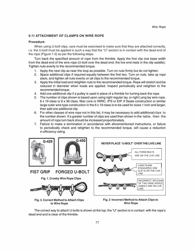
77
Wire Rope
9.11 ATTACHMENT OF CLAMPS ON WIRE ROPE
ProcedureWhen using U-bolt clips, care must be exercised to make sure that they are attached correctly,
i.e. the U-bolt must be applied in such a way that the “U” section is in contact with the dead end ofthe rope (Figure 1-3) as per the following steps.
Turn back the specified amount of rope from the thimble. Apply the first clip one base widthfrom the dead end of the wire rope (U-bolt over the dead end, the live end rests in the clip saddle).Tighten nuts evenly to the recommended torque.
1. Apply the next clip as near the loop as possible. Turn on nuts firmly but do not tighten.2. Space additional clips if required equally between the first two. Turn on nuts, take up rope
slack, and tighten all nuts evenly on all clips to the recommended torque.3. Apply the initial load and retighten nuts to the recommended torque. Rope will stretch and be
reduced in diameter when loads are applied. Inspect periodically and retighten to therecommended torque.
4. Add one additional clip if a pulley is used in place of a thimble for turning back the rope.5. The number of clips shown is based upon using right regular lay, or right Lang lay wire rope,
6 x 19 class or 6 x 36 class, fiber core or IWRC, IPS or EIP. If Seale construction or similarlarge outer wire type construction in the 6 x 19 class is to be used for sizes 1 inch and larger,then add one additional clip.
6. For other classes of wire rope not in this list, it may be necessary to add additional clips tothe number shown. If a greater number of clips are used than shown in the table, then theamount of rope turn back should be increased proportionately.
7. Failure to make a termination in accordance with aforementioned instructions, or failureto periodically check and retighten to the recommended torque, will cause a reductionin efficiency rating.
The correct way to attach U-bolts is shown at the top; the “U” section is in contact with the rope’sdead end and is clear of the thimble.
NEVER PLACE “U-BOLT” OVER THE LIVE LINE
Fig. 1. Crosby Wire Rope Clips
Fig. 3. Correct Method to Attach Clipsto Wire Rope
Fig. 2 Incorrect Method to Attach Clips to Wire Rope
INCORRECT SPLICINGOF TWO WIRE ROPES,UNBOLT ARE ON LIVELINE
U-BOLTS ARESTAGGARED, ONECLIP IS ON THE LIVELINE
ALL THREE BOLTS
ARE ON THE LIVE LINE
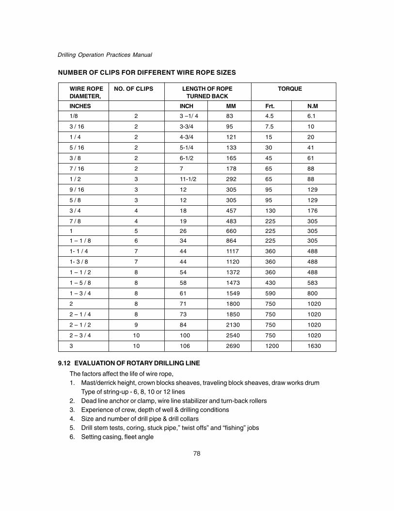
78
Drilling Operation Practices Manual
NUMBER OF CLIPS FOR DIFFERENT WIRE ROPE SIZES
WIRE ROPE NO. OF CLIPS LENGTH OF ROPE TORQUEDIAMETER, TURNED BACK
INCHES INCH MM Frt. N.M
1/8 2 3 –1/ 4 83 4.5 6.1
3 / 16 2 3-3/4 95 7.5 10
1 / 4 2 4-3/4 121 15 20
5 / 16 2 5-1/4 133 30 41
3 / 8 2 6-1/2 165 45 61
7 / 16 2 7 178 65 88
1 / 2 3 11-1/2 292 65 88
9 / 16 3 12 305 95 129
5 / 8 3 12 305 95 129
3 / 4 4 18 457 130 176
7 / 8 4 19 483 225 305
1 5 26 660 225 305
1 – 1 / 8 6 34 864 225 305
1- 1 / 4 7 44 1117 360 488
1- 3 / 8 7 44 1120 360 488
1 – 1 / 2 8 54 1372 360 488
1 – 5 / 8 8 58 1473 430 583
1 – 3 / 4 8 61 1549 590 800
2 8 71 1800 750 1020
2 – 1 / 4 8 73 1850 750 1020
2 – 1 / 2 9 84 2130 750 1020
2 – 3 / 4 10 100 2540 750 1020
3 10 106 2690 1200 1630
9.12 EVALUATION OF ROTARY DRILLING LINE
The factors affect the life of wire rope,1. Mast/derrick height, crown blocks sheaves, traveling block sheaves, draw works drum
Type of string-up - 6, 8, 10 or 12 lines2. Dead line anchor or clamp, wire line stabilizer and turn-back rollers3. Experience of crew, depth of well & drilling conditions4. Size and number of drill pipe & drill collars5. Drill stem tests, coring, stuck pipe,” twist offs” and “fishing” jobs6. Setting casing, fleet angle

79
Wire Rope
TON- MILE CALCULATION• Heavy wear would occur in a few localized sections where the rope makes contactwith the
traveling block sheaves, and where the rope makes contact with the crown block sheaveswhen the slips are pulled going in or coming out of the hole, and on the drum where eachwrap of rope crosses over the rope on the layer below. Broken wires at these points ofcritical wear would result in the retirement of the entire string up, even though the remainderof the rope is in good condition.
• Do not cut too much wire rope frequently, there will be an obvious waste of usable drillingline, which will result in higher than necessary rig operating costs. However, if the rope ismoved through the reeving system too slowly, sooner or later some section of the drillingline will become worn and damaged to such an extent that there will be a danger of failure,injury to personnel, damage to equipment and expensive downtime. At the very least, it willbe necessary to make a “long cut” to eliminate some broken wires.
• For these reasons, it is important that the drilling line be cut at the proper rate. The purposeof this simplified cut-off practice is to give the drilling crew a method for keeping track ofthe amount of work done by the drilling line, and a systematic procedure for making cutsof the appropriate length at the appropriate time. The objective is to obtain maximum ropeservice without jeopardizing the safety of the rig operation.
• In conjunction with the record keeping required for the cut-off procedure, daily visual inspectionof the drilling line should be made for broken wires and any other rope damage. It must beremembered that in all cases, visual inspection of the wire rope by the drilling crew musttake precedence over any pre-determined calculations.
• The only complicated part of a cut-off procedure is the determination of how much workhas been done by the wire rope. Methods such as counting the number of wells drilled orkeeping track of days between cuts are not accurate because the load changes with depthand with different drilling conditions. The various operations performed (drilling, coring, fishing,setting casing, etc.) subject the rope to different amounts of wear.
• For an accurate record of the amount of work done by a drilling line, it is necessary tocalculate the weight being lifted and the distance it is raised and lowered. In engineeringterms, work is measured in foot-pounds. On a drilling rig the loads and distances are sogreat that we use “ton-miles.” One ton-mile equals 10,560,000 foot-pounds, and is equivalentto lifting 2,000 pounds a distance of 5,280 feet.
• Use the Ton-mile indicator.
FORMULA FOR WORK DONE: Total work done by line during trip is equal to;
T =2000 x 5280
M 4D WmD)D(Ls 2C ⎟⎠⎞
⎜⎝⎛ +++
where;D = Depth of the hole in meter ft,Ls = Length of drill pipe stand, meter ftN = Number of stands of drill pipe,Wm = Effective weight of drill pipe lb/ft.

80
Drilling Operation Practices Manual
M = Total weight of traveling block assembly lbC = Effective weight of drill collar minus the effective weight of same length of drill pipe lbT = Ton miles
Note : For round trip work done will be twice of the calculated above.
9.13 CUT-OFF PROGRAM
So long as the maximum ton-mile accumulation shown on the program is not exceeded, a cutmay be made whenever it is convenient. It is only necessary to total the ton-miles accumulated sincethe last cut and divide by 19.0 to determine what length to cut. This way the ton-miles per foot cutwill always be exactly 19.0, and the wear on the drilling line will be uniformly spread along itslength.
1. Work done can be calculated by the following method. During slip and cut operations thetravelling equipment (block and hook) will be properly secured with hanging off pendantsso that inadvertent movement is not possible. Slip & cut programs should be continuallyevaluated to maximize efficiency and minimize waste.
2. Whatever program is used, it should be followed throughout the life of one entire drillingline. If no long cuts are required, and it is believed that more service can be obtained froma line, the goal can be raised one ton-mile per foot cut. This procedure should be followeduntil the optimum goal is found.
3. Daily visual inspection of the drilling line should be made for broken wires and any otherrope damage.
4. Avoid accumulating more ton-miles between cuts than the maximum shown on the programfor your rig even on the first cut of a new line.
5. It is best not to run up to the maximum permitted ton-miles each time between making acut, as some problem on your rig could prevent a cut being made at the proper time andlead to a ton-mile over run. A better approach is to bounce around on your program,cutting with a new ton-mile accumulation sometimes and alternating with a medium or higherton-mile accumulations. This practice does not waste wire rope because you are alwayscutting off lengths in proportion to the work accumulated.
6. Accurate measurement of the length to cut is very important. A steel tape should be usedwhen making this measurement.
7. When stringing back from 12 to 10 lines, or from 10 to 8 lines, make a cut of the appropriatelength based upon the ton-mile accumulation at that time. This procedure will shift thecritical wear points on the rope during heavy operations such as casing lowering.
8. Keep your wire rope history sheets accurate and complete.9. Calculate ton-miles during drilling after each round trip. Failure to record Ton-miles during
drilling is probably the most common mistake made in cut-off practice.10. The best cut-off program is the one with the most consistent ton-mile per foot cut values.
By staying as close as possible to the Ton-mile goal you will avoid long cuts and maintainthe safest and most economical use of drilling line.
11. No. of slips between cut offs can vary considerably depending upon drilling conditions andon the length and frequency of cut offs.

81
Wire Rope
9.14 CUT-OFF PRACTICE FOR DRILLING LINE
Cumulative work before first Cut- off
Work done by a wire line in Ton -miles with respect to height of mast & diameter of wire line forthe first cut can be obtained as:
Derrick Formation Total work of drilling line before the first cut offor Mast Hardness 1” 1 1/8” 1 1/4” 1 3/8” 1 1/2”
Height (ft)Ton miles Ton miles Ton miles Ton miles Ton miles
80-87 Very hard 500Hard 500Medium 500Soft 600
94-100 Very hard 500 600Hard 500 700Medium 500 800Soft 600 900
126-131 Very hard 600 1000Hard 700 1100Medium 800 1200
Soft 900 1300
133-138 Very hard 600 1000Hard 700 1100Medium 800 1200Soft 900 1300
142-147 Very hard 1000 1600Hard 1100 1800Medium 1200 2000Soft 1300 2100
187-189 Very hard 1600 2000Hard 1800 2200Medium 2000 2400Soft 2100 2600
Note: All the ton-miles in the table have been calculated using a safety factor of 5.Every body isaware of that this safety factor often falls consistently below 5
CALCULATION OF WORK DONEHeight of mast: 138 ft, wire rope diameter: 1 ¼”, drum diameter: 28 inches, safety factor: 3
Say you are operating at a safety factor of 4 then total work done found in the table must bemultiplied by 0.8. Ans: For S.F.= 5, the total work done is 1100 T-miles. For S.F = 3 curve (fig.4a,b below) gives the corrective fig: = 0.58 Then the total work done is = 1100 x .58 .i.e. 638T-miles

82
Drilling Operation Practices Manual
2. RECOMMENDED CUT OFF LENGTHS FOR ROTARY DRILLING LINES
Drim diameter (inch)MASTHEIGHT 11 12 14 16 18 20 22 24 26 28 30 32 34 36 (ft)
Cut off length in meters and number of drum laps (1)
187 34.6 34.7 34.5 33.9 3315½ 14½ 13½ 12½ 11½(1)
142-143 25.9 25.9 25.7 27.5 26.8-147 13½ 12½ 11½ 11½ 10½
133-136 24.7 25.5 23.9 23.9 25.7 25.1 24.3-138 15½ 14½ 12½ 11½ 11½ 10½ 9½
126-129 22.3 22.3 23.1 21.9 23.9 23.9 23.5 22.7 24.3-131 17½ 15½ 14½ 12½ 12½ 11½ 10½ 9½ 9 ½
94-96 20.2 19.6 18.5 18 18.4 18.4 18.2 19.7 19.0-100 19½ 17½ 14½ 12½ 11½ 10½ 9½ 9½ 8½
87 18.2 19.7 19.0 16.517½ 14½ 12½ 11½
66 11.0 12.012½ 11½
(1) In order to change the point of cross over on the drum, where wear and crushing are most sever, the laps to be cut are given in multiples of one-half lap.Note: Cut off length in metre is mentioned in bold letters in top line whereas no of wraps to cut off isgiven below the cut off length.
DESIGN FACTOR
Fig. 4b:
RELATIONSHIP BETWEEN ROTATRY LINEINITIAL LENGTH AND SERVICE LIFE
Fig. 4a:
10
9
8
7
6
5
4
3
2
2000 3000 4000 5000 6000 7000
Based on cutoff programindicated in Fig.
1.5
1.0
0.5
0 1 2 3 4 5 6 7
TONMILESERVICEFACTOR
No. of wraps per cut-off

83
Wire Rope
9.15 PRECAUTIONS WHILE USING WIRE ROPE1. Avoid developing of kink caused by pulling down a loop in a slack line during improper handling.
Early rope failure will undoubtedly occur at this point.2. Avoid bird caging caused by sudden release of tension and resultant rebound of rope from over
loaded condition.3. Inspect localized wear over an equalizing sheave carefully because it is not visible during
operations of wire rope.4. Avoid ‘strand nicking’ which is caused by adjacent strand rubbing against on another and is
usually caused by core failure due to continued operation of rope under high tension. In thisindividual wire rope breaks in the valleys of the strands.
5. Avoid fatigue failure of wire rope subjected to heavy loads over small sheaves.6. Avoid fatigue break in a cable tool drill line caused by a tight kink developed in the during
operation.7. Wire line tolerances are given below in table;
Nominal dia of rope, inch Undersize, inch Oversize, inch
0 to 3/4 0 1/32
1-3/16 to 1-1/8 0 3/64
1-3/16 to 1-1/2 0 1/16
Place sheave gauges in grooves as shown (Fig. 5)
Detail “A” reflects gauge fit in a sheave.
Detail “B” reflects gauge “fit” in a worn (tight groove) sheave.
Detail “C” reflects gauge “fit” in a sheave where the groove is too large.
Sheave grooves in the crown and traveling blocks should be checked at the time of installation a
new line. Sheave grooves must neither be too small nor too large to avoid damage to the line.
Small grooves cause pinching and over heating, large grooves allow flattening of the line.
Detail BGroove Too Small
Detail ACorrect Size Groove
Detail CGroove Too Wide
Fig. 5. Grooves too small, just right, and too big

84
Drilling Operation Practices Manual
Rope diameter, inch Sheave diameter, inches
Recommended (6 X19) Mini (6 X 19)
7/8 39 26
1 45 30
1-1/8 50 34
1-1/4 56 38
1-3/8 62 41
1-1/2 67 45
9.16 ATTACHING LINE AND SHEAVE DIAMETERS
Bending of the drilling line over sheaves reduces the amount of load it can carry. For the bendingitself puts a load on the line. Hence diameter of the sheave should be big enough for drilling line.When wire rope is used over sheaves that are too small its service life is reduced. Bending causes re-adjustment of the positions of the wires and strands as well as bending of the wires themselves.Such re-adjustment, which must occur continuously in the multiple –line reeving system, causesfatigue. Wires in drilling line will break by continuously bending it backward and forward. To minimizethe fatigue of the drilling line due to bending sheave diameters should be with in the following limits;Table No….

85
Well Head Fitting
CHAPTER -10WELL HEAD FITTING
After WOC, casing head housing which is the first well head component to be installed is fittedon the surface casing. Casing head housing serves as a connector from the surface casing to theBOP stack during drilling and then to other subsequent well head components. It has a bowl toaccept a casing hanger to suspend the intermediate casing. The following procedure is adopted.
1. Remove false conductor / Riser.2. Cut the surface casing at a suitable height from the bottom of the cellar pit. The height
is calculated as under:
Deduct the total height of all the well head components except the tubing spool from the depthof the cellar pit. The height obtained is the height at which the surface casing should be cut fromthe cellar pit bottom. Care should also be exercised so that welding of the surface casing to thecasing head housing can be done easily.
1. The marks are put all around the surface of the casing at a number of points and then acircular marking is done.
2. Cut casing and chamfer properly on the inside.3. The weld –on housing of the casing head is slipped on the cut casing and is kept perfectly
horizontal and welded from both inside and outside using the proper type of weldingelectrodes.
4. The welded casing head housing is allowed to air cool.
10.1 TYPES OF CASING HEAD HOUSINGCasing head housing are available in two different types:1. Threaded Bottom.2. Welded Bottom
1. THREADED BOTTOMThe threaded bottom housing is furnished with API casing threads so that they may be screwed
on to the casing pipe. Both the female as well as male threaded housing are available.
a) Female Threaded BottomThis housing is screwed directly on casing and is considered standard since one housingcan be used for all weights and grades of a particular size casing.
b) Male Threaded Bottom
In order to screw the casing head housing directly on to the coupling of the casing, housingwith male threaded bottom are used.
The use of such housing is discouraged due to the following reasons:
1. In terms of strength the API casing head material is equivalent to J-55 casing. Thismeans that in the event that a male threaded housing is screwed on N-80 or P-110grade casing, the male thread on the casing head would be the weakest connectionbecause it would be equivalent to J-55.
2. The bore through such type of casing housing must match the casing ID which willvary not only for different casing sizes but also for the different pipe weights within agiven range.

86
Drilling Operation Practices Manual
2. SLIP ON WELD TYPE HOUSING
This type of housing is equipped with a socket weld preparation which slips over the casingand has provision for welding top of the casing to the ID of the housing and also for welding thebottom of the housing to the OD of the casing. One housing can be used over all the weights andgrades of a particular size casing. Test port is provided to test the quality of welding. Housing/Bowlflange should be aligned with respect to the cellar pit.
Outlets on the casing head housing
Outlets are provided on the casing head housings for access to the annulus. Threaded outlets,flanged outlets or a combination thereof are available. Either one or two outlets can be provided.
10.2 INSTALLATION OF WELLHEAD SEALS
A. Installation of Primary Seals (National Well Head )
1. Remove burrs from the cut end of the casing, drop the lower packing support with the lipface up over the casing and into the body counter bore.
2. Thoroughly clean and lubricate with oil the casing as well as inner and outer surfaces ofseals and put one side of the seal lip over the casing. Tap progressively all around therubber packing with a hammer until the casing has completely entered the inner lips.Care must be taken to avoid damage to the lips of the rubber packing.
3. After the outer lips have fully entered the bevel in Bowl, drive the packing down until it isflush with the body flange.
4. Place the upper packing support with the lip receiving face down over the casing and dropit into place.
B. Installation of Secondary Seals
1. Drop the lower secondary seal packing support with its lip face up over the casing.2. Install the rubber packing as per procedure explained for installation of primary lip seal
packing.3. Install the upper secondary packing support.4. Thus secondary packing is installed.
Installation of Next Casing or Tubing Spool
1. Place the ring gasket in its groove.2. Install the next casing spool or tubing spool on to the well head assembly keeping the
flanges matching the flange on the casing head on the bottom and bolt up properly.
10.3 TESTING OF CASING HEAD CONNECTIONS
1. After installing the different parts of a well head, testing is carried out to determine theeffectiveness of the field installed seals and connections.
2. The pressure should not exceed the lowest pressure determined from the following:• Working pressure of connection.• Load restriction on primary seal.• Collapse pressure of the pipe after taking into consideration safety factor.

87
Well Head Fitting
• Load restriction on secondary seal.• Working pressure of end or outlet connection.• Working pressure rating of the spool.• Internal yield pressure of pipe after taking into consideration safety factor.
Installation of Primary and Secondary Seals (National)
A D
B
C
E
F
G

88
Drilling Operation Practices Manual
10.4 RUNNING PROCEDURE FOR 3 CASING POLICY WELLHEAD (BHEL)
SYSTEM DESCRIPTION
The Typical production system consists of the following casing sizes:
Typical Flange Sizes & Ratings for 3CP WELLHEAD:
(1) 3000 psi Wellhead: 13-5/8" - 3000 x 11" - 3000 x 7-1/16” - 3000 psi
(2) 5000 psi Wellhead :13-5/8" - 3000 x 11" -5000 x 7-1/16" - 5000 psi
(3) 10000 psi Wellhead:13-5/8" - 5000 x 11" -10000 x 7-1/16" -10000 psi
ASSEMBLY / CONTRACT DRAWINGS
10.4.1 Installation Procedures
10.4.1.1 13-3/8" Casing and Wellhead Equipment
a. Installation of 13-5/8"nominal casing head threaded bottom connection1. Pick up the 13-3/8" Male threaded Casing of the required length.2. Pick up the casing head and orientate it, taking into consideration wing valve directions and
make up with the Male threaded Casing.3. Nipple up BOP and riser with the flange connections.
b. Slip on welded bottom connection1. Cut the casing at the desired height above the cellar pit level. Smooth and level the casing.
2. Pick up the casing head and orientate it, taking into consideration wing valve directions and
slip it over the casing.
3. Ensure that the casing has entered the socket weld preparation and the Casing Head is
seated correctly.

89
Well Head Fitting
4. Remove the ½” LP plug from the Casing Head. Weld the Casing to the Casing Head takinginto consideration the material of the Casing Head (Low Alloy Steel) and Casing materialcombination and stress relieve.
5. After the welds have cooled, seal test the welds via test port to a maximum WorkingPressure, but do not exceed 80% of the casing collapse pressure. After successful test,place ½” LP Plug.
6. Nipple up BOP and riser with the flange connections.
10.4.1.2 Running The 13-5/8" Test Plug1. Make up the 13-5/8" Nom.Test plug assembly to the drill string.2. Run the 13-5/8" Nom. Test Plug assembly on the drill string and land it in the casing head
bowl.3. Test the BOP and connections above the 13-5/8" Nom. Test Plug Assembly by pressurizing
through the drill string and bypass in the 13-5/8" Test Plug assembly.4. Remove the test Plug after testing.5. Drill hole for 9-5/8" casing to prescribed depth.
Note: It is recommended to use BHEL 13-5/8" Nom. bore protector while drilling to protectthe casing head inner surface from damage.
10.4.2 9-5/8" Casing and Wellhead Equipment
10.4.2.1 Installation Of 13-5/8 "Nomx 9-5/8" Casing Hanger
Installation of Casing Hanger (BCMBNS / BCMBFNS) is as follows:
BHEL Make BCMBNS and BCMBFNS slips incorporate a new controlled make up principlethat permits casing string loads equivalent to the pipe body strength to be handled with a controlledpipe Inner Diameter. The design is such that when light to medium casing loads are supported,there are radial gaps between the segments. Increasing the load of the suspended casing completelycloses the gaps. The fully loaded slip assembly resembles and reacts as a continuous, solid ringwith a fixed Inner Diameter. The dimensions selected for these slips compensate for the tubularmill tolerances, so that maximum casing loads can be supported without reducing the casing InnerDiameter below the API drift diameter. The 45° shoulder on the casing head / spool body furnishesa solid supporting surface for the fully loaded slip unit.
A) Type Bcmbns Casing Slips
Type BCMBNS casing slips are three piece hinged assemblies with a simple latch permittingthem to be closed around the casing and lowered through BOP.
B) Type Bcmbfns Casing Slip & Seal Hangers
The BCMBFNS hanger is an automatic suspend-and-seal unit. It utilizes a metal hinge and asimple integral latch pin. It can be wrapped around the casing and lowered through preventers.Upon reaching the bowl in the casing body, it grips and suspends the casing string. The annulusis automatically and effectively sealed upon slack off. No manual adjustments are necessarybefore installation or after slack off. Excessive packing pressure is relieved, avoiding any possibilityof deformed casing when maximum string lengths are suspended. Type BB primary packingshould be used with this hanger.

90
Drilling Operation Practices Manual
Item No. Part Name No.Off Material
1 Slip Segment 3 Steel Carburized
2 Drive Pin 5 Hardened Steel
3 Hinge Plate 3 Steel
4 Hinge Pin 1 Steel
5 Eye Bolt 2 Steel
Guidelines for Installing Casing Hangers (Slip Assembly): Fig.1
Fig:1 : Type Bcmbns Slip Type Casing Hangers
1. Casing shall be spaced so that there shall be no collar located between the points of assemblyabove the BOP stack and the casing head / spool which would prevent the hangers fromsliding down the BOP into position.
2. Hold the casing to desired tension. Do not slack off.
3. Position two boards across the top of the BOP stack / casing head.
4. Remove the hinged pin (Item No.4) to open out the slip assembly
5. Wrap the slip assembly around the casing, place it on the boards and reinstall the hinge pin.
6. Remove the support boards. Lower the slip assembly through the BOP stack / casing head /spool and land it in the casing head / spool.
7. Slack off the casing tension slowly to actuate the slips. No movement of the casing assuresthat the slips have gripped.
8. Part the BOP stack.
9. Mark and cut off casing approximately 4" (102 mm) above the upper surface of Casing HeadFlange.
25
1
4
3

91
Well Head Fitting
Guidelines For Installing Bcmbfns Casing Hangers (Slip Seal Assembly) : Fig.2
Item No. Part Name No.Off Material
1 Spider 2 60K Steel
2 Slip 4 Steel Carburised
3 Hinge Pin-Fixed 1 Steel
4 Hinge Latch Pin 1 Steel
5 Seal 1 Buna-N
6 Shouldered Screw 4 Steel
7 Pin-Slip (Not shown) 4 Steel
8 Eye Bolt 2 Steel
Fig. 2: Type Bcmbfns Slip & Seal Casing Hangers
1. Casing shall be spaced so that there shall be no collar located between the points of assemblyabove the BOP stack and the casing head / spool which would prevent the hangers fromsliding down the BOP into position.
2. Hold the casing to desired tension. Do not slack off.3. Position two boards across the top of the BOP stack / casing head.4. Remove the hinge latch pin (Item No.4) to open out the slip assembly.5. Wrap the slip assembly around the casing, place it on the boards and re-install the hinge latch
pin.(Ensure that Item 6 (Shouldered Screws) is free to move and not binding on the body)6. Remove the support boards. Lower the slip seal assembly through the BOP stack / casing
head / spool and land it in the casing head / spool.7. Slack off the casing tension slowly to actuate the slips. No movement of the casing assures
that the slips have gripped.
Note : If the slip assembly has not gripped, slip teeth are to be checked for sharpness.
8
4
16
5
2 3

92
Drilling Operation Practices Manual
8. Part the BOP stack.
9. Mark and cut off casing approximately 4" (102 mm) above the upper surface of Casing HeadFlange.
10.4.2.2 Installation Of Primary Packing 13-5/8" Nom X 9-5/8"1. Pick and drop 13-5/8"Nom x 9-5/8" Primary packing lower support with the lip receiving
face up over the casing and seat it into the Casing Head body counter bore.
2. Clean and grease the casing as well as the inner and outer surfaces of the Primary packingand slide one side of the packing lip over the casing. Tap progressively around the packingwith a hammer until the casing has completely entered the inner lips.
Caution : Do not cut or gouge the lips of the Packing during installation.
3 After the outer lips have fully entered the bevel in the bowl, drive the Packing down until itis flush with the body flange.
Note: If the wing valve outlet is open, entrapped air will not hinder seating of packing.
4. Place the upper packing support, with the lip receiving face down over the casing, drop anddrive it until it is flush with the Body Flange.
10.4.2.3 Installation of Secondary Packing 13-5/8"Nom X 9-5/8"Install the Secondary Packing group by dropping the lower support with its lip receiving face up
and then install the packing and upper support as described in Step 10.4.2.2.
10.4.2.4 Installation Of Casing Spool1. Place Ring Gasket in place on the Casing Head flange.2. Lower the casing spool over the Casing Head flange and carefully orientate it, taking into
consideration wing valve directions.3. Make up the bottom flanged connection with stud bolts and nuts.4. Hook up test pump to test port on lower flange of Casing spool. Test to maximum Working
Pressure or 80% of collapse pressure of casing whichever is minimum.
Note : Remove Check Valve from test port before testing.5. Bleed off test pressure, remove test pump and install check valve.6. Reinstall Seal plug.7. Nipple up BOP and riser.
10.4.2.5 Running The 11"Nom.
TEST PLUG BUSHING1. Make up 11" Test plug assembly to the drill string.2. Run the 11" Test Plug assembly on the drill string and land it in the casing spool bowl.3. Test the BOP and connections above the 11"Nom.Test Plug Assembly by pressurising
through the drill string and bypass in the 11" Nominal Test Plug assembly. Remove thetest Plug after testing.
4. Drill hole for 7"/ 5½” casing to prescribed depth.
Note : It is recommended to use BHEL 11" Bore Protector while drilling to protect the CasingSpool inner surface from damage.

93
Well Head Fitting
10.4.3 7" / 5½” CASING AND WELLHEAD EQUIPMENT
10.4.3.1 Installation of 11 "Nom x 7" / 5½” Casing Hanger
See Sl. No. 2.2.1 for construction and installation of the Casing Hanger (BCMBNS/ BCMBFNS) .1. Run the 7"/ 5½” casing. Space out the casing so that there is no collar located between the
point of assembly above the BOP stack and the Casing Head/spool which would prevent thehanger from sliding down the BOP into position.
2. Center and Hold the 7" / 5½” casing to desired tension. Do not slack Off.3. Position two boards across the top of the BOP Stack.4. Open the hanger assembly by removing the latch pin wraps it around the 7" / 5½” Casing,
place it on the Board and make up the latch pin.
Note : Type BCMBFNS - Casing Hangers is an automatic suspend and seal unit. It utilizes ametal hinge pin and a simple integral latch pin. It can be wrapped around the casing and loweredthrough BOP. Upon reaching the bowl in the casing spool body, it grips and suspends the casingstring. The annulus is automatically and effectively sealed off upon slack off. No manual adjustmentsare necessary.
5. Remove Support boards. Lower the hanger through BOP Stack and make sure that the Hangerhas seated in the Casing Spool.
6. Slack off the tension slowly to actuate the slips. Ensure that the slips have gripped the.casingsecurely.
7. Part the BOP stack.8. Mark and cut off casing approximately 4" (102 mm) above the upper surface of Casing Spool
Flange.9. Remove burrs from the cut edges of the casing and ensure that the edge is smooth and level.
10.4.3.2 Installation of Primary Packing 11"Nom x 7" / 5½”1. Pick and drop 11"Nom x 7"/ 5½” Primary packing lower support with the lip receiving face up
over the casing and seat it into the Casing Spool body counter bore.2. Clean and grease the casing as well as the inner and outer surfaces of the Primary packing
and slide one side of the packing lip over the casing. Tap progressively around the packingwith a hammer until the casing has completely entered the inner lips.
Caution: Do not cut or gouge the lips of the Packing during installation.
3. After the outer lips have fully entered the bevel in the bowl, drive the Packing down until it isflush with the Body Flange.
Note: If entrapped air hinders seating of packing, relieve the entrapped air through the inner / outerside of the primary packing using a screw driver.
4. Place the upper packing support, with the lip receiving face down over the casing, drop anddrive it until it is flush with the Body Flange.
10.4.3.3 Installation of Secondary Packing 11"Nom. - 7" / 5½”
Install the Secondary Packing group by dropping the lower support with its lip receiving face upand then install the packing and upper support as described in Step 10.4.2.3.

94
Drilling Operation Practices Manual
10.4.3.4 Installation of tubing spool1. Place Ring Gasket in place on the Casing Spool flange.
2. Pick up TUBING SPOOL and orientate it, taking into consideration wing valve directions andlower it over 7"/ 5½” Csg. carefully.
3. Make up the bottom flanged connection with stud bolts and nuts.
4. Hook up test pump to test port on lower flange of tubing spool. Test to maximum WorkingPressure or 80% of collapse pressure of casing whichever is minimum.
Note : Remove Check Valve from test port before testing.
5. Bleed off test pressure, remove test pump and install check valve.
6. Reinstall Seal plug.
7. Nipple up BOP and riser.
10.4.3.5 Running the 7-1/16 "Nom. Test Plug Bushing1. Make up 7-1/16" Test plug assembly to the drill string.
2. Run the Test Plug assembly on the drill string and land it in the Tubing spool bowl.
Note: Anchor screws on the Tubing head are to be backed out before lowering the 7-1/16" Nom.Test plug assembly.
3. Test the BOP and connections above the 7-1/16" Test Plug Assembly by pressurising through
the drill string and bypass in the 7-1/16" Test Plug assembly.
4. Remove the test Plug after testing.
5. Drill hole to suit the 3½” / 2-7/8" Tubing.
Note : It is recommended to use BHEL 7-1/16"Bore Protector while drilling to protect the TubingSpool inner surface from damage.
10.5 3½” / 2-7/8" TUBING AND WELLHEAD EQUIPMENT
10.5.1 Installation of 7-1/16" Nominal Tubing Hanger1. Run the Tubing (along with Control line simultaneously, in case Control line provision is required)
with the last joint suspended in the rotary slips.
2. Make up the Tubing Hanger bottom connection to the last joint of tubing to be run. Ensure thatthe Neck Seals are fitted in their respective grooves. In case of Control line provision, installthe control line assay in the following manner:
a) Install swage lock fitting in the bottom of Hanger body. Tighten the fitting.
b) Connect the control line to the Tubing Hanger inlet. Strap the control line with the Tubing.
3. Connect the Back pressure valve Plug in the Back pressure valve and install the Assembly inthe Hanger.
4. Ensure that the Anchor Screws around the Tubing Spool are backed out.
5. Lower the Tubing Hanger through the BOP stack into the Tubing spool bowl.
6. Run in the Anchor Screws around the Tubing Spool to hold the Tubing Hanger in place.
7. Back out and retrieve the landing joint.
8. Nipple down the BOP stack and riser, being careful not to damage the sealing surfaces on theTubing Hanger.

95
Well Head Fitting
10.5.2 INSTALLATION OF X-MAS TREE
The complete X-mass tree has been assembled and tested in the plant prior to delivery to the wellsite.
1. Inspect Ring grooves at the bottom of X-Mass tree and top of Tubing Spool.
2. Install Ring Joint Gaskets in the Tubing Spool.
3. Lower the X-MAS TREE on to the Tubing Spool and make up the Flanged connection usingthe Stud bolts and nuts.
4. Test the connection through the test port on the bottom flange of X-mass Tree Bonnet.
5. In case of provision for Control line exit through Bonnet, connect the control line in thefollowing manner:
6. Install swage lock fitting at the Bonnet exit location. Tighten the fitting.
7. Connect the control line to Bonnet Exit.
8. Open all Valves.
9. In the case of Actuator operated valves, remove the 1/2" NPT Seal Plug and apply the RatedControl line pressure through the 1/2" NPT Inlet Port. Then remove the Thread Protector andShipping Washer. Reinstall the Thread protector.
10. Test Tree to the Rated Working pressure.
96
Drilling Operation Practices Manual
CHAPTER - 11BOP STACK
11.1 BLOWOUT PREVENTER SIZINGThe required BOP equipment must be selected in such a manner that vertical bore is sufficient
enough to pass the casing, casing hanger, casing slip and seal assembly, bit and other drilling toolslikely to be used and the following points must be kept in mind while selecting the BOP stack.
A. Space between top of cellar pit and bottom of rotary tableBlowout preventer stack configuration is to be selected on the basis of available space and fordifferent types of rigs owned by ONGC.
B. Matching connection to the size & press rating of w/head flangesAt different stages of drilling, the BOP stack is installed on various section of wellhead. If
the ratedworking pressure and size of wellhead flange does not match with the BOP stack, it leads to theuse of adopter flanges. While designing BOP stack efforts should be made to use minimumnumber of flange connections on the stack. Working pressure rating of wellhead should be equalor more than the maximum expected surface pressure as estimated for selection of blowoutpreventer.
C. Service conditions
Service conditions refer to the following aspects:1. Environment operations i.e. urban, rural or isolated place to ensure required degree of protection
for men, equipment and ecological environment.2. Corrosiveness of drilling fluids and formation fluids:
e.g. H2S environment requires H2S trim blowout prevention equipment to resist Sulphide stresscracking. Some blends of drilling and completion fluids can have detrimental effects on elastomercompounds. The original equipment manufacturer should be consulted regarding compatibilitywith drilling and completion fluids.
3. Availability of BOP spare parts at drill site, storage facilities (specially for rubberized parts),inventory management, etc. Nitrile elastomeric components may be suitable for H2S serviceprovided drilling fluids are properly treated.
4. Infrastructure facilities to repair test and replace BOP and its sub assemblies.
D. Minimum requirement criteriaa) BOP stack must withstand the maximum well head pressure estimated as per calculations.b) The internal bore should be large enough to pass the drilling tools and tubulars required for the
subsequent operations.c) The stack must have provision for inlet and outlet of fluid under controlled pressure.d) Annular BOPs may have a one step lower rated working pressure than the ram BOPs.

97
BOP Stack
Table
Rated working Min. vertical Ring joint gasketpressure, psi bore, in
R / RX BX
2 M 16 ¾ 65 -21 ¼ 73 -
3 M 7 1/16 45 -9 49 -11 53 -13 5/8 57 -20 ¾ 74 -
5 M 7 1/16 46 -11 54 -13 5/8 - 16016 ¾ - 16218 ¾ - 16321 ¼ - 165
10 M 7 1/16 - 1569 - 15711 - 15813 5/8 - 15916 ¾ - 16218 ¾ - 16421 ¼ - 166
15 M / 20 M 7 1/16 - 1569 - 15711 - 15813 5/8 - 159
M = 1000 psi
11.2 NOMENCLATUREBlowout prevention system consists of blowout preventer stack, kill line, choke line, choke and kill
manifold, closing unit, diverter and auxiliary equipment.
Component code adopted for designation of BOP stack configuration as per API RP-53 is givenbelow:
G - Rotating headA - Annular type blowout preventerR - Single ram type preventerRd - Double ram type preventer with two sets of rams.Rt - Triple ram type preventer with three sets of rams.S - Drilling spool with side outlets for connecting choke and kill lines.M - 1000 psi rated working pressure.

98
Drilling Operation Practices Manual
Components are listed reading upwards from the uppermost piece of permanent well head equipmentor from bottom of the preventer stack. A blowout preventer stack may be fully identified by a very simpledesignation such as : 5M, 13 5/8”, RSRdA.
This preventer stack would be rated 5000 psi working pressure and would have through bore of 135/8”.
Ram type preventers should be equipped with extension hand wheels for manual locking orhydraulically operated locks.
11.3 BASIC COMPONENTS OF BOP STACK
a) Annular PreventerThe Annular Preventer is designed to close and seal over the open hole or around different shapessuch as square and hexagonal kelly, tool joint etc including wire line except stabiliser and bit.
b) Ram Type PreventerPipe ram is designed to close and seal around a pre designated size of pipe, whereas, presentlyavailable variable rams can seal around a pre designated range of pipe size. Blind ram is used toclose and seal an open hole. However, these days blind cum shear rams are in use, which canshear the pipe and seal the open hole as well.
Note : Pipe rams are not designed to close and seal around tool joint and coupling.
c) Drilling SpoolsChoke and kill lines may be connected either to side outlets of the BOPs or to a Drilling spoolinstalled below at least one Ram BOP. Utilization of the BOP side outlets reduces the number ofstack connections and over all BOP stack height. However, a drilling spool is used to providestack outlets (to localise possible erosion in the less expensive spool) and to allow additionalspace between preventers to facilitate stripping, hang off, and/or shear operations.
Criteria for Drilling Spoolsa) 3M and 5M arrangements should have two side outlets no smaller than a 2-inch nominal
diameter and be flanged, studded, or hubbed. 10M, 15M, and 20M arrangements should havetwo side outlets of minimum 3-inch nominal diameter and should be flanged, studded orhubbed.
b) It shall have a vertical bore diameter equal to that of mating BOPs and at least equal to themaximum bore of the upper most casing/tubing head.
c) It shall have a rated working pressure equal to the rated working pressure of the installed ramBOP. For drilling operations, well head outlets should not be employed for choke and kill lines.
d) Choke Manifold and Choke LinesThe choke manifold consists of high pressure pipe, fittings, flanges, valves and manual and/orhydraulic operated adjustable chokes. This manifold may bleed off well bore pressure at a controlledrate or may stop fluid flow from the well bore completely, as required.
Choke ManifoldRecommended practices for installation (Surface installation):

99
BOP Stack
a) Manifold equipment subject to well and/or pump pressure (normally upstream of and includingthe chokes) should have a working pressure equal to or greater than the rated working pressureof the ram BOPs in use.
b) The choke manifold should be placed in a readily accessible location, preferably outside therig structure.
c) All choke manifold valves should be full bore. Minimum two valves are recommended in chokeline immediately after the BOP stack with rated working pressure equal or greater than therated working pressure of Ram BOP in use. One of these two valves should be remotelycontrolled. During operations, all valves should be either fully opened or fully closed.
d) A minimum of one remotely operated choke should be installed on 10000 psi and above ratedworking pressure manifolds. Generally, remote operated choke is not installed in 5000 psiworking pressure manifold. If conditions dictate like for example the frequency of use of chokesis high, it will be prudent to use a remote choke (in addition to adjustable choke) in 5000 psiworking pressure choke manifold. Choke manifold configurations should allow for re-routing offlow without interrupting flow control.
e) Pressure gauges suitable for operating pressure and drilling fluid service should be installedso that drill pipe and annulus pressures may be accurately monitored and readily observed atthe station where well control operations are to be conducted.
f) Rig air systems should be checked to ensure their adequacy to provide the necessary pressureand volume required different controls. The remotely operated choke should be equipped withan emergency back up system such as a manual pump for use in the event air becomesunavailable.
Installation guidelines – choke linesThe choke line and manifold provides a means of applying back pressure on the formation while
circulating out influx from the well bore.
The choke line and lines downstream of the choke should:a) 1. Be as straight as possible. Wherever the bends, blocks and tees are provided, they
should be targeted to minimize erosion.2. For flexible lines, manufacturer’s guidelines should be consulted on working minimum
bend radius to ensure proper length determination and safe working configuration.b) Be firmly anchored to prevent excessive whip or vibration.c) 1. Have a bore of sufficient size to prevent excessive erosion or fluid friction. Minimum
recommended size for choke lines as per API is 2” nominal diameter or 3M and 5Marrangements and 3” nominal diameter for 10M and above rated arrangements.
2. Minimum recommended nominal inside diameter for lines downstream of the chokesshould be equal to or greater than the nominal connection size of the chokes.
3. For air or gas drilling operations, minimum 4” nominal diameter lines are recommended.4. The bleed line that bypasses the chokes should be at least equal in diameter to the
choke line.
Kill lines and kill manifoldKill lines are an integral part of the surface equipment required for well control during drilling. The
kill line system provides a means of pumping into the well bore when the normal method of circulatingdown through the kelly or drill pipe can not be employed. The kill line connects the drilling fluid pumps

100
Drilling Operation Practices Manual
to a side outlet on the BOP stack. The location of the kill line connection to the stack depends on theparticular configuration of BOPs and spools employed; the connection should be below the ram typeBOP most likely to be operated.
Installation guidelines - kill linesa) All lines, valves, check valves and flow fittings should have a working pressure at least
equal to the rated working pressure of the ram BOPs in use.b) For working pressures of 3000 psi and above, flanged, welded, hubbed or other end
connections that are in accordance with API Specification 6A, should be employed.c) Components should be of sufficient diameter to permit reasonable pumping rates without
excessive friction. The minimum recommended size is 2-inch nominal diameter.d) As per API, two full bore manual valves plus a check valve or two full bore valves (one of which
is remotely operated) between the stack outlet and kill line are recommended for installationswith rated working pressure of 5000 psi or greater.
e) Lines should be as straight as possible. When bends are required to accommodate eitherdimensional variations on sequential rig ups or to facilitate hook up to the BOP, the largestbend radius allowable under the hook up restraints should be provided. For flexible lines,manufacturer’s guidelines should be followed to ensure safe working configuration.
f) All lines should be firmly anchored to prevent excessive whip or vibration.g) The kill line should not be used as fill-up line during normal drilling operations.
Standard choke and kill manifoldThe standard choke and kill manifolds in use/ available in ONGC are:i) 4 1/16” –5000 psi working pressure.ii) 4 1/16” –10000 psi working pressure.iii) 3 1/16” –15000 psi working pressure.
11.4 INSTALLATION OF BOPThe first step in fitting BOP is the installation of a drilling spool over well head.1. Clean the casing head flange and put steel ring gasket of correct type and rating.2. Clean both the flanges of the spacer spool, if required to use.3. Fit a spacer spool above the casing head. The length of the spacer spool should be so
adjusted that the upper face of the spacer spool comes in line with the ground level. Both theflanges of the spacer spool should be of the same rating and size as the casing head flange.
4. Install Ram type preventor equipped with pipe rams matching with drill pipe sizes to beused (incase of 10,000/15,000 psi BOP stack).
5. Install drilling spool on the spacer spool or pipe ram BOP, if needed.6. Care should be taken to select the drilling spool having flanges of same pressure rating as
that of the BOP.7. The two diametrically opposite side outlets should have the same pressure rating as choke
and kill lines respectively.8. The vertical bore should be at least equal to the maximum inner diameter of the inner most
casing.9. While installing drilling spool, the two side outlets of the spool should point in the direction
in which choke and kill lines are to be fitted.

101
BOP Stack
10. Lift double ram BOP so that the BOP’s upper position in on the top side. Top rubber seal of therams should be on the upper side. The arrow marking on BOP also indicates top position.
11. Place the correct ring gasket in the groove on the drilling spool.12. Slowly tower BOP (the direction of the BOP handles should be so kept that BOP rams can
be easily operated) and rest BOP on the drilling spool.13. Tighten the double ram BOP on the drilling spool (in case the studs can not be put from
below the drilling spool or from above the BOP then the same are to be positioned in thedrilling spool before lowering BOP).
14. Clean the top ring groove of the ram type BOP, put the ring gasket of correct size and rating.15. Lift annular BOP and slowly install it above double ram BOP taking proper care to keep the
fluid outlet valves on the sides so that the fluid lines can be easily fitted.16. Clean the ring groove above the annular BOP and install the ring and the flow nipple to
facilitate the flow of mud from the well bore to the shale shaker.17. Connect BOP handles on the double ram BOPs ensuring that manually operated shafts
and wheels must extend beyond the substructure boundary and be easily accessible.18. Erect a shield of wooden planks over control wheels of preventers and on the wall in front of
the hand wheel, the direction and number of turns which are required for preventer closureshould be displayed by an arrow in red paint.
Installation of Choke and Kill Line
Kill Line1. Fit the adapter spool with the drilling spool.2. Using proper ring gasket and studs and nuts tighten two valves of proper rating with the
adapter spool.3. Install one tee after the valves and fit a pressure gauge in the blind flange having threaded
opening for fitting the pressure gauge.4. Install one non – return valve.5. Install one tee of proper rating.6. Install the line from mud pump on one side and a line from the cementing unit from the
other side of the tee. Install valve on this line.
Choke Line1. Install the adapter spool (if required).2. Connect one valve (stand by valve).3. Install the remote control hydraulic valve.4. Connect choke flow line having flanges of required rating at both the ends between the
hydraulically operated valve and the choke manifold.
Choke Manifold1. As chokes get worn out due to erosion or plugging with large formation particles it is essential
to provide chokes in parallel to the flow line, thereby necessitating the installation of amanifold called the choke manifold.
2. Hydraulically operated or manually operated chokes are installed in the choke manifold.3. Strategically placed gate valves will permit the use of one choke while the others are
disconnected.4. Two valves should be installed ahead of each choke to be used for regulating the flow.

102
Drilling Operation Practices Manual
5. The choke manifold should have one connection from the manifold after the choke to the mudtank and one connecton to the flare line.
6. The pressure rating of various valves in the choke line prior to choke and in the full bore lineshould be equal to or more than the pressure rating of the BOP.
11.5 RECOMMENDED PROCEDURE FOR TESTING BOP STACK AND ALLIED EQUIPMENTSince all the equipments used in well control are essential to the safety of the well, the crew
members, the rig and the surrounding environment; testing procedures of these vital surface BOPequipment becomes an important integral part of the drilling programme. For optimum control of anywell kick situations successful functioning of the blowout preventer stack, choke and kill lines andother related equipment at their rated capabilities becomes pertinent.
The only way to make certain and ensure that the equipment will perform at its rated capacitywhen needed is by adhering to regular test procedures. The situation requires both rigorous testprocedures that evaluate pressure integrity of all parts in the system and at the same time exposingthe equipment to periodical function tests will keep the equipment in readiness for operations inaddition to suggesting if any maintenance work is required to be carried out in advance.
All the important considerations for BOP stack testing and the test procedures are discussed.
11.5.1 Need of Periodic TestingConsidering many likely causes of failure of blowout preventer equipment, the need for periodic
testing of BOP’s assumes a great importance and is a must. The purpose of various field tests ofBOPs (well control equipment) is to verify:
a) Those specific functions are operationally ready.b) The pressure integrity of the installed equipment.c) The control system and BOP compatibility.
It becomes pertinent to identify the causes and take remedial measures in order to rectify thesame.
11.6 REASONS OF FAILURE OF BOP STACK AND CHOKE AND KILL MANIFOLD• Equipment may not have been installed properly.• Vibrations and extra loading during drilling operation may cause leak.• Lines and fittings may be abraded by mud flow.• Cement, baryte and sand may sometimes accumulate or settle out and plug.• Corrosion may cause damage to choke lines & equipment.• Partially closed valve may get eroded.• With passage of time, rubber sealing elements may get deteriorated and fail when subjected
to test conditions.• Badly stored items, when used may not perform at rated capacity.• Normal wear and tear also results in malfunction of the equipment.• Rubber sealing elements and packers may not be compatible with the mud system or
subsurface environment such as temperature.
11.6.1 Important ConsiderationsImportant considerations in blowout preventer testing are :

103
BOP Stack
• Test fluids• Test pressures• Testing equipments• Test procedures and their frequency• Test duration
A. Test FluidsIn normal application, clear water is considered as the best test fluid, as drilling fluid may plugsmall leaks. It should be ensured that air is removed from the system before test pressure isapplied.
B. Test PressuresAll BOP components that may be exposed to well pressure should be tested first to a low pressureof 200 to 300 psi and then to a high pressure.
i. Low pressure test:The stack is generally washed and cleaned with water before testing. However, it is possiblethat existence of dry mud particles may be covering a potential leak spot. In such caseshigh pressure test may pack the mud particle in the leak spot and affect a temporary seal.Hence low pressure test of 200 to 300 psi is recommended for rams , annular preventers,manifolds, lower kelly cock, etc. Also in performing a low pressure test, do not apply a highpressure and bleed down to low pressure. Should a leak occur at low pressure, correctiveremedial measure may be taken accordingly at this stage.
ii. High pressure test:After initial installation of BOP on well head,i. Rams, choke manifold and choke/ kill lines should be tested to the rated working pressure
of the ram BOPs or to the rated working pressure of the well head on which the stack isinstalled, which ever is lower.
ii. Annular BOPs may be tested to 70% of the rated working pressure or to the test pressureapplied to the ram BOPs, which ever is lower.
iii. Lower kelly cock, kelly, upper kelly cock and drill pipe safety valve should be tested to therated working pressure.
iv. In case of instances where available BOP stack and / or the well head has higher workingpressure than are required for the specific well bore conditions due to equipment availability,a site specific well control test programme can be followed.
Subsequent high pressure test of ram BOPs and choke manifold should be limited to a pressuregreater than the maximum anticipated surface pressure but not to exceed the working presure ofthe ram BOPs. The maximum anticipated surface pressure should be determined by the operatorbased on specific well conditions.
Annular BOPs should be tested to a minimum of 70% of their working pressure or to the testpressure of ram BOPs, which ever is lesser. In case of downstream valves of choke and kill lines,test pressure on initial as well as subsequent tests should be limited to 50% of its rated workingpressure.
C. Test DurationA stable low test pressure as well as stable high test pressure should be maintained for at least5 minutes.

104
Drilling Operation Practices Manual
Fig. 3. Testing BOP with Cup Tester / Test Plug
D. Test Frequency
Function test: All operational components of the BOP equipment systems should be functiontested at least once a week.
Pressure test: Pressure test on the well control equipment should be conducted at leasta) Prior to spud or upon installationb) After the repair/ disconnection of any pressure containment seal in the BOP stack, choke line
or choke manifold, but limited to the affected component.c) Not to exceed 21 days.
E. Testing EquipmentFollowing equipments are usually used while testing BOP equipment :
a) Pumps: The pumps used to generate pressures for testing may be any type i.e. capableof attaining the desired pressures. A small high pressure pump is generally used inmost of the testing applications. Cementing units with of desired high pressure rating cansafely be used if conveniently available.
b) Test plugs: While testing BOP stack and other equipment, test plug must be used toisolate the entire casing and open hole from the applied test pressures. These test plugs areset in the bottom of the preventers, there by preventing communication of pressure below thetest plug.
c) Commonly used test tools are :• cup tester• test plug
Fig. 1. Cup Tester Fig. 2. Test Plug

105
BOP Stack
Cup Tester
It has a mandrel with box connection on top, a cup and a sub with pin connector on bottom.The cup of the tester gives effective sealing in the casing. At the time of pressure testing, thecup tester is made up on drill pipe and should be lowered to be placed in the casing oppositeto the slips in the casing spool or casing head. After filling the stack with water, the pipe ramsor the annular is closed. Pressure is built up by pumping down the kill lines to provide desiredpressure. The limitations of the cup tester:1. Since cup tester is freely hanging in the casing, tension load on pipe will increase with
increase in test pressure. Higher grade of drill pipe to be used as test pipe other wise yieldstrength of drill pipe may limit the test pressures.
2. BOP pressure test will be limited to 70-80% of the burst rating of upper part of casing.3. This can not be used to test blind/ shear blind rams.
Test Plug
Test plugs have mainly a box on top to connect test pipe and pin on bottom to add someweight on it. These test plugs are designed to seat in well head. With seal on the body itisolates the upper part of the well head and the well bore. This plug is to be lowered and landedinto the well head with a test drill pipe joint after adding few stands of HWDP or equivalentweight to the bottom. This added weight of drill collars will help in seating properly in the wellhead and give proper sealing. To test the blind or shear blind ram, test pipe should be removed,leaving the test plug resting on the well head.
Care must be taken while using test plug for its designed compatibility with the existing wellhead used. Different makes of well head have different types of test plugs. So, while loweringtest plug it should be confirmed this plug is compatible with the well head used other wise itmay get stuck and can lead to another problem which will result in loss of valuable rig time.
d) Casing ram test sub: To facilitate testing of casing ram it is essential to have the casingram test sub. It can be connected between the test plug and test joint after making suitableend connections so that the sub is positioned against the casing ram to be tested.
F. Testing Procedure
Testing procedures are integral part of the drilling program and as such a specific programmeof equipment testing is mandatory.Testing procedures are discussed under heads:• function (actuation) testing• pressure (hydraulic) testing
FUNCTION TESTFunction test is performed to verify the component’s intended operations.i. The test (ram BOP and annular BOP) should be conducted when the drill string is inside
casing.ii. Test should be conducted after installing FOSV/ inside BOP on drill string.iii. Both pneumatic and electric pump of accumulator unit should be turned off after
recordinginitial accumulatorpressure.

106
Drilling Operation Practices Manual
iv. All the ram preventers ( except blind/shear) and HCR’s in choke/kill line should befunctiontested and closing time should be recorded.
v. Blind ram should be operated for function test when drill string is out of hole.vi. Pipe ram should be closed against correct size pipe in the hole.vii. Operation of shear ram should be kept to bare minimum.viii. Closing time should not exceed 30 seconds for all ram preventers and annular preventers
smaller than 18 3/4” closing time should not exceed 45 sec for annular preventer of 18 3/4”and larger size.
ix. Function test should be carried out alternatively from main control unit/derrick floor panel/auxiliary panel.
x. Record final accumulator pressure after all the functions should not be less than 1200 psior 200 psi above the pre charged pressure of accumulator which ever is maximum.
xi. All the gate valves and blow out preventers should be returned to their original position andcontinue normal operations.
xii. All the results should be recorded in the prescribed formats.
PRESSURE TESTING
Testing of Blind Ram (Ref fig. 4)
i. Make up appropriate casing head test plug on a stand of drill collar and run in the same ona joint of drill pipe. Set the plug in casing head seat. Back off and remove drill pipe joint.Ensure that test plug size, shape and contour matches with that of casing head where itwill seat.
ii. Fill preventers with water. Open all the valves and chokes in choke line and choke manifoldand allow water to flow through each out let. Flush all the lines and BOP with water.
iii. Open both the valves on casing head below test plug seals to recognize leaking seals aswell as well activity and prevent formation or casing damage in case of any leakage throughtest plug.
iv. Close valve nos. 7,9 on choke line and valve nos. 2,3 on kill line and close valve no.43.
v. Fill and top up BOP with water.
vi. Close blind ram with 1500 psi closing pressure.
vii. Check closing line and preventer for leaks.
viii. Apply pressure by cementing unit or high pressure test unit through main kill line andpressurise upto 200 to 300 psi and hold for 5 minutes. If pressure is holding, test up tofinal test pressure as decided. Again hold for at least for 5 minutes.
ix. If there is a drop in pressure, check all the valves, flanges, and seals that are under pressure.Also check blind ram and test plug for leaks. If leakage is observed corrective action maybe taken after releasing pressures and opening blind ram. Retest the blind ram as detailedabove.
x. Open blind rams with 1500 psi. Check opening lines for leaks.
xi. Record test results.

107
BOP Stack
Testing of Annular BOP and Pipe Rams (Ref fig. 5)i. Flush lines flushed with water.ii. Make up test plug with sufficient weight and rest test plug at well head.iii. Run in appropriate size (smallest size of drill pipe to be used in case of testing of annular
BOP) of drill pipe and make up with test plug.iv. Ensure that integral port in the test plug is open.v. Fill up drill pipe with water. Make up FOSV on top of drill pipe.vi. Close valve No 7,9 on choke line and valve no 3,6 on kill line.vii. Close annular preventer with appropriate closing pressure as per manufacture
recommendation.viii. Check closing line and annular preventer for leaks.
CHOKE MANIFOLD
12 16 17
18
19
23
24
22
27
28
31
26
25 13
14
15 21
20
29
PIPE RAM
BLIND RAM
CHOKE LINEKILL LINE
PIPE RAM
TESTING PLUG WITH PORTSCASING HEAD
FROM CEMENTINGPUMP
1 2 3 8
4 5 6 9 10 11
43
7
ANNULARFROM MUDPUMPS
35 40
34 33
36
37 39
38 41
42
TESTING OF BLIND RAM
LEGEND FLOW DIRECTION
VALVE CLOSED
VALVE OPEN
30
Fig. 4. Testing of Blind Ram

108
Drilling Operation Practices Manual
Fig. 5. Testing of Annular BOP and Pipe Rams
ix. Apply test pressure through drill pipe and raise pressure to 200 to 300 psi and hold for5 minutes. Check for any leakage. If pressure is holding, increase the pressure upto finaltest pressure and hold for at least 5 minutes.
x. Check for leaks and release pressures.xi. Open annular preventer.xii. Now close upper pipe ram with 1500 psi.xiii. Check closing line and preventer for leaks.xiv. Again, apply test pressure through drill pipe and raise pressure upto 200 to 300 psi and
hold for five minutes. Check for any leakage. If the pressure is holding, then increase thepressure upto final test pressure and hold for at least 5 minutes.
xv. Test pressure should be limited to the pressure rating of the weakest member exposedto the test pressure.
xvi. Check for leaks and release pressures.xvii. Open pipe rams with 1500 psi.
LEGEND FLOW DIRECTION
VALVE CLOSED
VALVE OPEN
CHOKE MANIFOLDANNULAR
PIPE RAM
BLIND RAM
CHOKE LINEKILL LINE
PIPE RAM
TESTING PLUG WITH PORTSCASING HEAD
FROM CEMENTINGPUMP
FROM MUDPUMPS
TEST PRESSURETHROUGH DRILLPIPE
1 2 3 7 8
4 5 6 9 10 11
12 16
17
18
19
23
24
22
27
28
31
30
26
25 13
14
15 21
20
32
35 40
34
33
36
37 39
38
41
42
29
43
TESTING OF PIPE RAMS AND ANNULAR BOP

109
BOP Stack
xviii.Check opening lines and preventer for leaks.xix. Test all other pipe rams in this manner by repeating step no. ix to xiv. Make sure that the
pipe rams size fits the drill pipe size in the well, if not change the drill pipe and then testthe rams. Variable bore rams should be initially pressure tested on the largest and smallestOD pipe sizes that may be used during the well operations
xx. If there is any leakage, corrective action may be taken after releasing pressure and retestedas per procedure detailed above.
Testing of Kill Line, Choke Line, Manifold Valves, Flanges and Fittings (Ref fig. 3)From the previous test with the test plug seated in casing head, the procedure mentioned
below is followed to conduct the above test:
i. Kill and choke lines and manifold fittings are flushed with water. For this purpose, closeupper pipe ram and open all valves and chokes on choke manifold to allow the flow of waterthrough each outlet.
ii. Close valves 3,6,7 and9 keeping upper pipe ram closed.
iii. Apply test pressure through drill pipe and raise pressure upto 200 to 300 psi and hold for 5minutes. Check for any leakage. If pressure is holding, then increase the pressure up tothe rating of the weakest member exposed to test pressure (same as that of ram BOP)and hold for 5 minutes.
iv. Next, open valves 3,6,7 and 9 and close 2,5,8 and 10. Repeat step 3.
v. To test check valve 1, open valve 2 and repeat step 3. Next close valves 44,32 and open
valve 2. Repeat step 3 to test check valve 4.
vi. Close valves 6,45 and open valve 2. Repeat step 3 to test 44 and 45.
vii. Open valves 44,45 and close 46. Repeat step 3 to test 46.
viii. Remove the spring loaded valve in the check valve no. 4 , so that other valves in the kill line
can be tested.
ix. Now close valves 43,11,12 and open valves 8,10. Repeat step 3.
x. Open valve 43 and close valve 37 and open valve 11 and close valves 15,16 and 17. Repeat
step iii.
xi. Open valve 37 and close 36,38,39 on kill line side. On choke manifold, open valves 15,16,17
and close valves 14,18 21,22 and 23. Repeat step iii.
xii. Next open valves 36,39 and close valves 33,34,35,40,41,42 on kill line side and open valves
14,18,21,23 and close choke 13,19,20,24 on the manifold. Repeat step iii.
xiii. Now open chokes 13,19,20,24 and close valves 25,26,27 and 28.
xiv. Apply test pressure and raise upto 200 to 300 psi and hold for 5 minutes. Check for any
leakage. If pressure is holding, increase the pressure up to 50 % of the rated working
pressure of components down stream of chokes. Hold pressure for at least 5 minutes.
xv. Finally, open valves 22,25,26,27,28 and close valves 29,30,31. Repeat step xi.
xvi. Check all valves, flanges and seals which are subjected to test pressure for leaks.
xvii. Release pressure and rectify the leakages if any. Re test the rectified components.

110
Drilling Operation Practices Manual
Fig. 6. Testing of Kill Line, Choke Line, Manifold Valves, Flanges and Fittings
CHOKE MANIFOLD
12 16
17
18
19
23
24
22
27
28
31
26
25 13
14
15 21
20
29
PIPE RAM
BLIND RAM
CHOKE LINEKILL LINE
PIPE RAM
TESTING PLUG WITH PORTS
FROM CEMENTINGPUMP
1 2 3 8
4 5 6 9 10 11
43
7
ANNULARFROM MUDPUMPS
35 40
34
33
36
37 39
38 41
42
TEST PRESSURETHROUGH DRILLPIPE
30
TESTING OF CHOKE AND KILL MANIFOLD VALVES
xviii.Record test pressures.
xix. Install check valves on the auxiliary and main kill line respectively.
xx. Remove test plug along with drill collar.
11.7 TESTING OF KELLY COCKS AND ROTARY HOSEPick up kelly, install full open safety valve on bottom of lower kelly cock. Using an adapter,
connect to a high pressure test pump or cementing pump. Open appropriate stand pipe valves andkelly valves. Fill system with water and close stand pipe valve. Pressurise to test rotary hose andkelly cocks in sequence.
An alternate method for testing kelly cocks and rotary hose will be to apply test pressure throughkill lines with test plug seated and pipe ram closed. Here, it is to be ensured that the port providedon the test plug body should be open.
LEGEND FLOW DIRECTION
VALVE CLOSED
VALVE OPEN
CASING HEAD

111
BOP Stack
Casing Test1. After testing of BOPs and choke and kill manifold,, the following sequence of operation are
followed to test casing.2. Run in drill string and bit, up to the top of the cement.3. Break circulation and test casings to 200 psi greater than the anticipated shoe test pressure.
Do not exceed 80% of the burst rating of the casing.
Drilling of Cement, Float Collar and Float Shoe1. Drill cement at 3 – 4 tonnes of weight on the bit and rotary rpm as 50-60 only.2. Drill float collar and float shoe carefully.3. Continue drilling till 0.5m below the casing shoe – formation should not be opened.4. Circulate the cuttings out of the well.
Shoe TestThis test is done to determine the complete of cement job around the shoe.
1. Pull the drill string in the casing.
2. Close pipe ram BOP and kelly cock.
3. Make cementing unit connection with choke line.
4. Flush the BOP stack, kill and choke lines with water.
5. Close gate valve on kill line.
6. Calculate the shoe test pressure. This is the sum of surface pressure and the hydrostaticpressure of the fluid being used during the test. It is equal to the hydrostatic pressure atthe shoe of the heaviest mud that will be used in the well before running the next string ofcasing volume pumped. (for plotting the graph see leak off test).
7. If the shoe is hermetical, the plot will be linear.
8. Hold the required test pressure for 15 min. The shoe is considered OK if the pressure doesnot fall more than 10% of the test pressure during this time.
9. Release the pressure through choke line, and measure the volume of fluid recovered andcompare this with the volume pumped. Both the volumes should be almost equal.
10. Open Kelly cock.
Note: In case the shoe does not hold up to the required pressure, squeeze cement and reportall the procedure for testing shoe.
11.8 MUD LINE SUSPENSION SYSTEMSMud line suspension systems provide temporary abandonment and re-entry capability for
exploratory, delineation, template, and other wells drilled from bottom-supported rigs. The variousMLS systems available in the market of leading brand Vetco are:
11.8.1 MLH Mudline Suspension System
The MLH midline suspension system has short, compact casing hangers with casing threadstop and bottom.

112
Drilling Operation Practices Manual
This system is used when a casing load suspension system is required but it is not tobe used to run and tieback at the mud line.
The MLH system is ideally suited for use on development platforms, and allows a major portionof the casing loads to be suspended at the mud line during drilling and completion of platform wellswith traditional surface equipment. It can also be used during jack-up drilling operations.
There is standard casing connections on top and bottom of each mud line casing hangerShoulders support the loads of the concentric casing strings, transferring the loads through thecollet to the previously installed hanger.
13-3/8” Mudline Hanger
20” Mudline Hanger
20” Landing Rig
9-5/8” Mudline Hanger

113
BOP Stack
20” Running Tool
13/38” Running Tool
9-5/8” Running Tool
20” Tieback Latch andLock Tool
13/38” Tieback Latch andLock Tool
9-5/8” Tieback Latchand Lock Tool
20” Mudline Casing Hanger
13/38” Mudline CasingHanger
9-5/8” Mudline CasingHanger
30” Landing Rig
RUNNING MODE TIEBACK MODE
11.8.2. Mud line MLC-E Suspension System

114
Drilling Operation Practices Manual
30" x 20" x 13-3/8" x 9-5/8" Casing ProgramThis is ideal for most jack-up drilled exploratory or development wells. MLC emphasizes simplicityand economy without sacrificing high pressure and hanging weight capacities.
30” x 1.00” Wall RL. 4LH Pin
13-38” Running Tool
20” MLC Casing Hanger
9-5/8” Running Tool
7” Casing Hanger
13-38” Casing Hanger
Clamp
9-5/8” Casing Hanger
7” Running Tool
Landing Joint
Split Centraliser
11.8.3 Slimhole Mudline System for Jack-up Drilling
115
BOP Stack
Features and Benefits- Generous washout ports in the running tool
Ensures no cement contamination around the running tool to give reliable well suspension.Indication at the rig floor that the wash ports are exposed.
- All casing hangers have robust left-hand threadsAllows for rapid operation and ease of removal at suspension.
- 13-3/8" and 9-5/8" casing hangers also have finer right-hand tieback threadsAllows for careful makeup of permanent metal-to-metal seal in tieback/productionapplications.
- Three metal-to-metal seal areas for running tool, corrosion cap and tieback tool on13-3/8" and 9-5/8" hangersThis gives a new seal area for each tool that is run into the hanger, hence giving maximumseal reliability.
- Over-torque protection on all running, tieback tools and corrosion capsProtects the seal area from damage due to incorrect installation, giving maximum seal reliability.
- Long lead in stab guidance
- Maximizes thread and seal protection.

116
Drilling Operation Practices Manual
CHAPTER - 12WELL CONTROL
KICKIt is defined as an influx or flow of formation fluid into the well-bore & can occur any time the
formation fluid pressure is greater than the bottom hole pressure being exerted in the well bore.
BLOWOUTIt is an uncontrolled flow of formation fluid at the surface or sub surface from the well bore. A
Blow-out is the result of an uncontrolled kick.
PRIMARY WELL CONTROLDuring normal drilling operations the hydrostatic pressure of drilling fluid is greater than the pressure
of the fluids in the formation. The maintenance of sufficient hydrostatic head exerted by drilling fluid tohold back the formation fluid pressure is termed as “Primary Well Control”.
SECONDARY WELL CONTROLIf due to any reason hydrostatic pressure in the well bore falls below the formation pressure,
formation fluid may enter in the well bore & if so happens, the primary control may be temporarily lostand a proper use of blow out preventers & kill procedures will provide Secondary well control, or in otherwords secondary well control involves detection & safe handling of kicks so as to re-establish primarywell control.
TERTIARY WELL CONTROLIt involves the techniques used to control a blow-out once the primary & Secondary Control are
lost. This primarily involves a re-establishment of the secondary control system such as : the well boreconduit, well head & BOP equipment & subsequently establishing the Primary Control.
12.1 CAUSES OF KICKSKicks occur as a result of formation pressure being greater than mud hydrostatic pressure which
causes fluid to flow from the formation into the well bore. The main factors which can lead to thiscondition can be classified as :
a) Improper hole fill up on trips.b) Swabbing.c) Abnormal formation pressure.d) Insufficient mud density.e) Lost circulation.f) Gas cut mud
More than 50% of the kicks occur due to first two of the causes listed above.
a) Improper hole fill up on tripsWhen the drill string is pulled out of the hole, the mud level decreases by a volume equivalentto the steel volume. If the hole does not take the calculated volume of mud, it is assumed aformation fluid has entered the wellbore. Even though gas or salt water entered the hole, the

117
Well Control
well may not flow until enough fluid has entered to reduce the hydrostatic pressure below theformation pressure.
Therefore, while pulling out the well should be filled continuously by using trip tank anddifferences of calculated and actual mud volume be recorded at regular interval. Similarly whilerunning in drill string, trip tank should be used to monitor displacement volume correctly atregular intervals.
If the hole is not filled to replace the steel volume, the fluid column in the wellbore shall godown and reduce the hydrostatic pressure. At the same time the pulling out of drill stringcauses a reduction in BHP due to swabbing effect. Therefore to avoid the possibility of anyformation fluid entering the bore hole due to combination of above two factors the hole shouldbe properly / regularly filled during tripping out.
In the field normally the practice is to fill up the hole either on a regular fill up schedule or to fillup continuously with a re-circulating trip tank. Irrespective of the practice being used anaccurate method of measuring the amount of fluid actually being taken by hole should bemonitored and an accurate record of actual volume v/s theoretical volume should be kept. If atany stage during pulling-out it is observed that the actual filled in volume is significantly lessthan volume of steel that has been removed, it means that some formation fluids must haveentered the wellbore.
b) SwabbingSwab pressures are created by pulling out the drill string from the borehole. It reduces thebottom hole pressure. If the reduced bottom hole pressure becomes less than the formationpressure, a potential kick may enter the well bore. Various factors conducive to swab pressuresare pipe pulling speed, mud properties, filtration cake, annular clearance, hole configurationand effect of balling up of BHA & bit.
c) Abnormal pressureIn case of wild cat or exploratory drilling, most often the formation pressures are not knownaccurately. While drilling, sometimes the bit suddenly penetrates an abnormal pressureformation. As a result the mud hydrostatic pressure becomes less than the formation pressureand may cause a well kick. There are various geological reasons for abnormal pressures.
d) Insufficient mud densityIf a formation is drilled using a mud density that exerts less hydrostatic pressure than the porepressure, the formation fluid may begin to flow into the well bore. Kicks caused by insufficientmud density seem to have the obvious solution of drilling with high mud density. The bestsolution is to maintain the mud density slightly greater than that required to balance theformation pressure in order to avoid mud loss.
e) Lost circulationLost circulation is another factor which reduces the hydrostatic pressure. When a kick occursdue to lost circulation, the problem may become more severe. A large volume of kick fluid mayenter the hole before the mud level increase is observed at the surface. It is a recommendedpractice to keep the annulus always topped to avoid considerable reduction in BHP when lostcirculation is encountered.
118
Drilling Operation Practices Manual
f) Gas cut mudGas contaminated mud will occasionally cause a kick. As the gas is circulated to the surface,it expands and reduces the hydrostatic pressure sufficient to allow a kick to enter. Althoughthe mud density is reduced considerably at the surface, the hydrostatic pressure is not reducedsignificantly since the most gas expansion occurs near surface & not at the bottom.
12.2 KICK INDICATION Following are the early warning signs & positive indications for kicks while drilling.
A. Early warning signsThe detection of increasing formation or pore pressure is very essential in maintaining primarycontrol of a well and preventing a kick. The early warning signs are indications of approachinghigher formation pressure which means that the well may go under-balance if no appropriateaction is taken. They are listed below :
i) Rate of Penetration TrendsWhen abnormal pressure formations are encountered, differential pressure & shale densityare decreased causing a gradual increase in ROP. An increase in drilling rate can be maskedby an increase in mud weight. Similarly bit weight changes can also mask the increase indrilling rate but careful observation of drilling rate or some such related parameter as “d”exponent can provide a timely warning of increasing pressure.
ii) Drilling BreakThe first indication of a possible well kick is a drilling break. For reservoir fluid to enter the wellbore there must be a permeable section of reservoir rock. This will cause a change in drillingrate. In soft formation, a sand section usually causes a sudden increase in drilling rate. Theincrease in drilling rate varies. A 200% to 300% increase in drilling rate is not unusual. In hardformations a reverse drilling break to a slower drilling rate occurs in the reservoir like sandstonethat are harder than the shale body.
iii) Increase in Torque & DragAs the difference between the mud hydrostatic pressure and formation pressure decreases(as a result of increasing formation pressure), the bit makes larger cuttings and the cuttingspile up around the collars and increase the rotary torque. Closing up of the hole may alsoincrease torque. Increase in rotary torque is a good indication of increasing pressure and apotential well kick. Drag & fill up on connections and trips increase when high pressureformations are drilled.
iv) Decrease in Shale DensityShale density usually increases with depth but decreases in abnormal pressure zones. Thedensity of cuttings can be determined at surface and plotted against depth. A normal trend lineis established and any deviation should theoretically indicate changes in pore pressure.
v) Change in Cutting Size and ShapesCuttings from normal pressure shale are small in size with rounded edges and are generallyflat. Cuttings drilled from abnormal pressured formation often become long and splintery withangular edges. As differential pressure is reduced due to increase in formation pressure, the

119
Well Control
cuttings have a tendency to explode off bottom. A change in cutting shape will be observedalong with an increase in the amount of cuttings recovered at the surface and this couldindicate that formation pressure in the well is increasing.
vi) Change in Mud PropertyAs the pressure in the formation increases faster than the pressure of the mud column, morecuttings & cavings will dissolve into the mud and increase the viscosity of the mud.
vii) Increase in Chloride Content in Mud FiltrateDrilling through high pressure formations having higher porosity results in contamination ofdrilling fluid with considerable volume of saline water from pores. This increases chloridecontent of the drilling fluid and its filtrate. A higher chloride trend can warn about increasingpore pressure.
viii)Increase in Flow Line TemperatureThe temperature gradient in abnormal pressure formation is usually higher than normalpressure formation. The continuous measurement of the mud temperature at the flow linegives an indication of change in temperature gradient associated with abnormally pressuredformation. The temperature may take a sharp increase (5-7oF/100 ft.) in transition zones.
ix) Increase in Trip, Connection and Back-ground GasAn increase in trip and / or connection gas should be considered as an indication that porepressure is increasing. Gas readings are arbitrary and are not proportional to actual gasconcentration in the mud. These vary considerably from one mud logging unit to another.Therefore absolute values of gas readings do not have much significance in detecting abnormalpressures. Increase in back ground gas is not very reliable in detecting pore pressure increase.This is because gas concentrations can change drastically in the formation being drilledwithout any increase in pore pressure.Gas analyzers are used to establish trend line which iscalled background gas. A gas feed in from a permeable zone will change this trend line. Theamount of feed in will determine the intensity of the trend change. Connection gas will normallyoccur on bottoms-up (calculated lag time) and if not re-circulated will not change the overalltrend line except for short interval of time. The most common error with gas cutting is thetendency to maintain the mud weight at its original value with addition of barite and withoutremoving all the gas. Since moderate gas cutting contributes so little to bottom hole pressurereduction, additional barite may increase the mud weight enough to cause lost circulation.
x) Change in ‘d’-exponentJordan and Shirley developed an equation for normalized penetration rate in which it wasdefined as a function of measured drilling rate, weight on bit, bit size and rotary speed in theequation as below:
d = log (R/60N)/log (12W/103 Db)Where,
R = rate of penetration in ft/hrN = rotary speed rpmW = weight on bit in 1000 lbsDb = bit diameter in inches
Since the d-exponent tends to indicate the pressure differential between formation pressure andwell bore pressure, mud weight will effect d -exponent. The original calculation should be correctedas follows:

120
Drilling Operation Practices Manual
dc = d× (MW1 ÷ MW2 ) where,
dc = modified d-exponent MW1 = mud density equivalent of formation fluid at normal pressure condition MW2 = mud density being used in well
dc values are plotted on a semi log graph paper at every 15 or 30 ft. interval depth to give normaltrend line. Abnormal pressure transition zone top is detected at the depth where dc exponentvalues against shale tend to decrease in comparison to normal values.
B. Positive Kick SignPositive kick indicators are different from kick warning signs. They indicate that the kick hasalready entered the well bore. Any of them indicate regular flow checks.
i) Increase in Return Flow (Pumps On)After the early warning signs the first positive kick sign is increase in flow rate at the flow linewithpumps on. The entrance of any fluid into the well bore causes the flow rate to increase.
ii) Flow from Well (Pumps Off)Stopping the pump causes a reduction in bottom hole pressure equivalent to the annularpressure drop, so flow check is a reliable method of checking for a well kick. If the welldoes not flow when the pump is shut off and remains static for two or three minutes, then nowell kick is entering.
iii) Pit Volume IncreaseAn increase in pit volume is obvious & positive indication of flow into the well bore & can beeasily verified. If an increase in pit volume is seen, shut off the pump and make a flow check.If the well does not flow, no kick is entering.
iv) Decrease in Pump Pressure and Increase in Pump StrokeIn case of kick there is under balanced condition between the fluid in the drill pipe and themixed column of mud and influx in the annulus. Therefore circulating pressure graduallydecreases and unless the pump throttle is changed, pump speed slowly increases.
12.3 KICK WHILE TRIPPINGWhen the pump is switched off, a reduction in BHP equal to annular pressure losses occurs. To
prevent kick while tripping, basic requirement is that hole must be kept full of mud and the volume ofmud required to fill the hole must be equal to the steel displacement of drill string pulled out. Thesequence of events to a kick while making a trip-out of hole is :
• Hole remains full or does not take proper amount of mud. Whenever suchsituation is noticed the pipe should be run back to bottom and mud iscirculated to clear the hole.
• Flow from the flow line• Increase in pit volume
The sequence of events leading to a kick while tripping-in the hole is:• The hole does not stop flowing during making connection between the stands• Increase in pit volume
In order to avoid well kicks while tripping, trip schedule must be made and trip tank must be usedto monitor the hole fill up (in case of tripping-out) and mud displacement (in case of tripping-in).

121
Well Control
12.4 TRIP MARGINDuring pulling out, upward motion of the drill string in the borehole (which is assumed to be full of
mud) creates a swab pressure. This decreases BHP when pipe is in motion. One way of minimisingthis is to use safe tripping speeds and having close monitoring of pipe volume pulled out & mud volumepumped in to keep the hole full. Another practice to tackle the problem is to keep mud weight gradientgreater than the formation pressure gradient. The resulting overbalance permits safe tripping andconnection operations. This extra mud weight is called trip margin. For normal drilling operation tripmargin is kept 0.2 to 0.3 ppg.
However, the swab pressure being a function of yield point (yp) of mud, trip margin can be calculatedas follows:-
Trip margin (ppg)= 8.33Yp ÷ 98 (dh-dp)Where
Yp = Yield point of mud in lbs/100 sq.ftDh = Hole diameter in inchesDp = Pipe outside diameter in inches
Effect of riser margin on maintaining bottom hole pressureIn the event of riser getting accidentally disconnected due to vessel drive-off or riser failure etc. the
bottom hole pressure shall be reduced due to loss of hydrostatic pressure as the riser mud column isreplaced by sea water. To compensate this reduction in bottom hole pressure, some margin has to beadded to the drilling mud density which is known as riser margin.
Example:Water depth - 700 ftRKB to sea level - 50 ftMud density - 11 ppgSeawater density - 8.5 ppgWell TVD - 10000 ft
Solution :RISER MARGIN (ppg) =
[ Air Gap + Water depth] x Mud density – [ Water Depth x Sea Water Density] ————————————————————————————————————
TVD – Air Gap – Water Depth
[ 50 + 700] x 11 – [ 700 x 8.5] —————————————— = 0.25 ppg
10000 – 50 – 700
Mud Density including Riser margin = 11+0.25 = 11.25 ppg
12.5 SLOW CIRCULATION RATEDuring well control operations, to avoid further entry of formation fluid it is essential to keep BHP
minimum equal to formation pressure. This is done by imposing certain calculated back pressure inaddition to system pressure losses on the well bore as long as old mud is in the well. Kicks have to becirculated out at slow circulation rates to ensure that the sum of this back pressure and system lossesdoes not exceed the rating of high pressure lines and other rig equipment. Various reasons forcirculating out the kicks at slow circulation rates are :-
a) To ensure that the slow circulation pressure plus the shut in drill pipe pressure is a convenienttotal pressure for the pump and does not exceed the surface line ratings.

122
Drilling Operation Practices Manual
b) To allow mud returns to be weighted up and re-circulated within the capabilities of availablemud mixing system.
c) To allow longer reaction time for choke adjustments. d) To allow sufficient time for disposal of kick fluid /de-gassing at the surface. e) To reduce the annular pressure losses.
The common practice so far had been to select a rate which is about half the pump speed at thetime of drilling. This practice was fairly good with duplex mud pump earlier in use on drilling rigs. Nowwith the use of triplex pumps this convention gives much higher speeds than the actual requirements.Theoretically speaking the kill rate or slow circulation rate should be the minimum possible pumpspeed at which pump can run smoothly without any knocking etc. But since at minimum pump speedsmore time will be required to kill the well, a compromise has to be made which can meet all therequirements. Therefore slow circulation rate should be 1/2 to 1/3 of pump SPM at the time of drilling.
Recording of slow circulation rateIt should be recorded near to the bottom for each pump at regular intervals and / or when drilling
conditions change such as:-i) At the beginning of each shift.ii) After change in drilling fluid density.iii) After change in bit nozzle size or BHA.iv) After drilling a long section of hole (500 ft.) in a shift.v) After pump fluid end repair.
On the rig there are a no. of places where drill pipe pressure gauges are installed such as standpipe, mud pumps, driller’s console, choke & kill manifold and remote choke panel. Slow circulationpressure should be recorded from the gauge that is to be used for well killing operation . So, it shouldbe recorded at remote choke panel, if available on the rig.
Choke line friction lossesIn subsea operations when circulating through choke, flow resistance in the extending choke line
running up from the sub sea BOP to surface is considerable. If pressure losses in choke line are nottaken into account during well killing, an excess pressure unnecessarily may be applied in the hole.Since fracture gradient generally decreases with increased water depth, so beyond 500ft water depthchoke line friction losses should always be considered while planning well control operations.
Measurement of chokes line friction lossesThere are three ways to find out choke line friction losses.These are :a) Pump down the choke line at slow circulation rate taking the returns into the riser through
open blow out preventer. The pressure thus shown on the choke manifold gauge is the chokeline friction losses. The value so obtained does include circulating pressure losses in the riserbut that is negligible.
b) Record circulating pressure at slow rate through riser with BOP open. Close BOP, open chokeline fail safe valve and record pressure with full choke open. The difference of the two values isthe choke line friction loss.
c) Pump down the choke line at slow circulation rate taking the returns through kill line with BOPclosed. The pressure thus shown on the choke manifold gauge is twice the choke line frictionlosses.
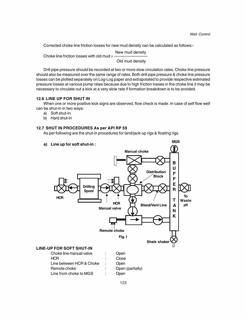
123
Well Control
Corrected choke line friction losses for new mud density can be calculated as follows:-
New mud densityChoke line friction losses with old mud × -————————
Old mud density
Drill pipe pressure should be recorded at two or more slow circulation rates. Choke line pressureshould also be measured over the same range of rates. Both drill pipe pressure & choke line pressurelosses can be plotted separately on Log-Log paper and extrapolated to provide respective estimatedpressure losses at various pump rates because due to high friction losses in the choke line it may benecessary to circulate out a kick at a very slow rate if formation breakdown is to be avoided.
12.6 LINE UP FOR SHUT INWhen one or more positive kick signs are observed, flow check is made. In case of self flow well
can be shut-in in two ways:a) Soft shut-inb) Hard shut-in
12.7 SHUT IN PROCEDURES As per API RP 59As per following are the shut-in procedures for land/jack-up rigs & floating rigs.
LINE-UP FOR SOFT SHUT-INChoke line manual valve : OpenHCR : CloseLine between HCR & Choke : OpenRemote choke : Open (partially)Line from choke to MGS : Open
a) Line up for soft shut-in :
Distribution Block
Bleed/Vent Line
Remote choke
HCR
HCR Manual valve
Shale shaker
ToWaste
pit
Manual choke
MGS
DrillingSpool
BUFFER
TANK
Fig. 1

124
Drilling Operation Practices Manual
b) Line up for hard shut-in :
LINE-UP FOR HARD SHUT-INChoke line manual valve : OpenHCR : CloseLine between HCR & Choke : OpenRemote choke : Open (partially)Line from choke to MGS : Open
Distribution Block
Bleed/Vent Line
Remote choke
HCR
ValveHCR
ToWaste
Pit
Manual choke
MGS
DrillingSpool
BUFFER
TANK
Shale shakerFig. 2
12.7.1 While Drilling on Land and Jack Up Rigsa) Stop rotary.b) Pick up kelly to clear tool joint above rotary table.c) Stop mud pump, check for self flow. If yes, close the well as follows
Sl.No. Soft Shut In Hard Shut In
i) Open hydraulic control valve (HCR valve) / Close Blow Out Preventer (Preferablymanual valve on choke line. Annular Preventer)
ii) Close Blow Out Preventer (Preferably Open HCR / manual valve on choke lineAnnular Preventer) when choke is in fully closed position.
iii) Gradually close adjustable choke, Allow pressure to stabilise and recordmonitoring casing pressure. SIDPP, SICP and Pit Gain.
iv) Allow the pressure to stabilise and recordSIDPP, SICP and Pit gain.

125
Well Control
12.7.2 While Tripping on Land and Jack Up Riga) Position tool joint above rotary table and set pipe on slips.b) Install full opening safety valve (FOSV) in open position & close it. Following methods are
recommended for shut in the well.
Sl.No. Soft Shut In Hard Shut In
i) Open HCR Valve / Manual valve on choke Close Blow Out preventer (Preferablyline. Annular Preventer)
ii) Close Blow Out Preventer (Preferably Open choke line HCR valve with chokeAnnular Preventer) is fully closed position.
iii) Gradually close adjustable choke, Make up kelly and open FOSVmonitoring casing pressure.
iv) Make up kelly and open FOSV Allow pressure to stabilise and recordSIDPP, SICP and Pit gain.
v) Allow the pressure to stabilise and record
SIDPP, SICP and Gain.
12.7.3 While String is Out of Hole on Land and Jack Up Rig (Soft Shut In)a) Open HCR valve on choke line.b) Close shear or blind ram.c) Close choke.d) Record SICP and pit gain.Note : In case of hard shut-in the sequence at a) & b) above shall be interchanged.
12.7.4 While Drilling on Floating Rig (Sub-sea)a) Stop rotary table.b) Raise kelly to hang off point ensuring that lower kelly cock is above rotary table and kelly is at
the pre-designated level so that tool joint is clear of ram preventers.c) Stop mud pump, check self flow. If yes, proceed further to shut in the well.d) Close annular BOP (Preferably upper annular)e) Open fail safe valve on choke line when remote choke is in close position.f) Close the upper pipe rams.g) Reduce hydraulic pressure on annular, hang the string and ensure rams are locked.h) Open annular after bleeding trapped pressure between annular and pipe ram.i) Record SIDPP, SICP and Pit Gain.
If motion compensator is not working or not reliable, following steps should be followed afterstep e) :
i) Set slips and close lower kelly cock. Bleed off stand pipe pressure and break away kellyabove kelly cock.
ii) Pick up circulating head make up the same above lower kelly cock, pick up the string tohang off point and remove slips.
iii) Close the upper pipe rams.iv) Reduce hydraulic pressure on annular hang the string and ensure rams are locked.v) Open annular BOP after bleeding trapped pressure between annular and pipe ram.vi) Open Lower kelly cock.

126
Drilling Operation Practices Manual
vii) Record SIDPP, SICP and Pit Gain.
12.7.5 While Tripping on Floating Rig (Sub-sea)i) Set slips below tool joint.ii) Install full open safety valve (FOSV) in open position, close it & remove slips.iii) Open Fail-safe valve on choke line when remote choke is in close position.iv) Close annular BOP.v) Calculate the length of the pup joint and /or length of stick up above rotary table to ensure that
the tool joint is clear off the pipe ram to be closed.vi) Make up kelly & open FOSV.vii) Close upper pipe rams. Reduce operating pressure on annular BOP.viii) Lower drill string & hang it off on the rams. Open Annular BOP after bleeding pressure.ix) Record SIDPP, SICP and pit gain.
12.7.6 When String is Out of Hole or Above the BOP on Floating Rig (Sub-sea)a) Open fail safe valve on choke line when choke is in close position.b) Close blind shear ram.c) Record shut-in pressure & pit gain.
12.8 SHUT IN PRESSURE INTERPRETATION
A. Shut-in Drill Pipe Pressure (SIDPP)The shut in pressure on the drill string side is the difference between the hydrostatic pressure ofdrilling fluid and the formation fluid pressure. When a kick enters during drilling, the drill stringremains uncontaminated whereas annulus becomes contaminated with influx. If SIDPP is addedto hydrostatic pressure of drilling fluid, the resultant pressure will be the pressure of theformation.
SIDPP is used to determine the kill mud weight required to balance the formation pressure byusing the equation given below
SIDPP(psi)Kill Mud Density (ppg) = —————————— + Original Mud Density(ppg)
0.052 × Well TVD( ft)
The shut in drill pipe pressure should be read & recorded from the gauge on the choke controlpanel. Since true SIDPP is determined for the calculation of kill mud density, it is recommended toread and record the SIDPP immediately after the closure and subsequently after every 3-5 minutes.The recorded values of SIDPP should be tabulated/plotted to ascertain the true value of SIDPP.Once the well is closed initially the SIDPP starts increasing till the BHP becomes equal to theformation pressure. The time taken for stabilisation depends upon the permeability of the formation.SIDPP may further increase but at a slower rate if the influx is gas/gas mixture.
B. Shut-in Casing Pressure (SICP)The shut in pressure on the annulus side is the difference between the combined fluid hydrostaticpressures and formation fluid pressure. Since annulus is contaminated with formation fluid (Oil,gas, salt water or combinations) therefore SICP can not be used to calculate kill mud densityhowever it is used to determine kind of influx which has entered the well bore. During kill operationcasing pressure will allow us to determine the pressure being exerted at various points in the wellbore and also pressures on the BOP equipment and choke lines.

127
Well Control
Example
A well was shut in after a kick, given below are the tabulated values of SIDPP and SICP. Find outthe stabilized value of SIDPP.
Time SIDPP(psi) SICP(psi)
0600 100 150
0605 200 270
0610 275 370
0615 340 450
0620 400 520
0625 405 525
0630 415 535
0635 430 550
0640 450 570
Note : Pressure recording should be done at every two minutes interval.
SolutionAs evident from tabulated values, SICP is increasing faster than SIDPP up-to 0620 hrs but later
both the pressures are rising by same amount. This shows that the pressures have stabilised at 0620hrs and subsequently due to close well gas migration both the pressures are rising by same amount.Therefore the value recorded at 0620 hrs i.e. 400 psi is the true SIDPP. The proper recognition ofstabilised value of SIDPP is very important as this value is used for the calculation of kill mud weightand formation pressure.
ExampleA well was shut in after a kick, given below are the tabulated values of SIDPP and SICP. Find out
the stabilised value of SIDPP.
Time SIDPP(psi) SICP(psi)
0800 150 200
0815 250 320
0830 340 420
0845 420 510
0900 500 600
0915 500 600
1000 500 600
1100 500 600
1115 505 605
1130 510 610
1145 520 620

128
Drilling Operation Practices Manual
SolutionAs is evident from tabulated values, SIDPP and SICP were increasing considerably up to 0900
hrs & later there is no change in the pressures up to 1100 hrs Therefore the value recorded at 0900hrs i.e. 500 psi is the stabilised value of SIDPP. Further increase in both the pressures is due toclosed well gas migration.
12.9 WELL KILLING PROCEDUREThe main principle involved in all well killing methods is to keep bottom hole pressure constant.
The various kill methods are as follows:1) Driller’s Method2) Wait and Weight Method3) Volumetric Method
In the first three methods the influx is circulated out and the heavy mud is pumped in the wellkeeping the bottom hole pressure constant. The fourth method i.e. Volumetric method is a noncirculating method in which the influx is brought out & heavy mud is placed in the well bore withoutcirculation.
Bringing the pump to kill speed on land / jack up rigIt is important to understand the start up procedure, irrespective of kill method, for bringing the
pump up to kill speed.
Pump should be brought to kill speed patiently. During this period if the casing pressure isallowed to increase it can cause formation breakdown or if the casing pressure is allowed todecrease it can cause entry of more influx into well bore. To prevent this, following procedure issuggested.
a) Bring the pump to kill speed slowly holding casing pressure constant by manipulatingchoke.
b) When the pump is at the desired kill speed follow the pressure schedule according to thekill method being used.
Note : While bringing the pump to kill speed keeping casing pressure constant, there might beslight reduction in bottom hole pressure due to expansion of gas but this is compensatedby the annular pressure losses.
12.9.1 Driller’s MethodIn Driller’s method the killing of a well is accomplished in two circulations• In first circulation the influx is removed from the well bore using original mud density.• In second circulation the kill mud replaces the original mud and restores the primary
controlof the well.
Formulae Required SIDPP (psi)
a) Kill Mud Weight (ppg) = Old Mud Weight + ———————- (ppg) 0.052 × TVD (ft)
b) Initial Circulating Pressure (ICP) = SIDPP(psi) + KRP (psi)

129
Well Control
Kill mud weight (ppg)c) Final Circulating Pressure (FCP) = ———————————— × KRP(psi)
Original mud weight (ppg)
Drill string volume (bbl)d) Surface to Bit Strokes = —————————————
Pump output (bbl/stroke)
Open hole annulus volume (bbl)e) Bit to Shoe Strokes = ——————————————
Pump output (bbl/stroke)
Annulus volume (bbl)f) Bit to Surface Strokes = —————————————
Pump output (bbl/stroke)
Killing Procedure (Drillers Method)
In this method the well is killed in two circulations.
• First Circulation
a) Bring the pump up to kill speed in steps of 5 SPM, gradually opening the choke holdingcasing pressure constant.
b) When the pump is up to kill speed, maintain drill pipe pressure constant.c) Circulate out the influx from the well maintaining drill pipe pressure constant.d) When the influx is out, stop the pump reducing the pump speed in steps of 5 SPM,
gradually closing the choke, maintaining casing pressure constant. Record pressure,SIDPP and SICP should be equal to original SIDPP.
Note : In case recorded SIDPP & SICP are equal but more than original SIDPP value, it indicatestrapped pressure in well bore. Whereas if SICP is more than original SIDPP, it indicatesthat some influx is still in the well bore.
• Second Circulation
a) Line up suction with kill mud.
b) Bring the pump up to kill speed in steps of 5 SPM, gradually opening the choke,
holding casing pressure constant.
c) When the pump is at kill speed, pump kill mud from surface to bit, maintaining casing
pressure constant.
d) Pump kill mud from bit to surface, maintaining drill pipe pressure constant equal toFCP.
e) When the kill mud reaches surface, stop the pump reducing the pump in steps of 5SPM, gradually closing the choke maintaining casing pressure constant. Recordpressures, SIDPP and SICP both should be equal to zero. Open & observe the well.Add trip margin before resuming normal operation.

130
Drilling Operation Practices Manual
Fig. 3. Pressure Profile- 1st Cycle of Driller’s Method
A - B Casing pressure rises as influx expands in drill collar annulus.
B - C Casing pressure decreases as influx crosses over from drill collar annulus to drill pipe
annulus & losses height.
C - D Casing pressure again rises as influx now expands in drill pipe annulus and it becomesmaximum when influx reaches surface at point ‘D’ on the graph.
D - E Casing pressure reduces sharply as influx is removed from the wellbore.
Drill Pipe Pressure GraphI - J Drill pipe pressure is held constant till the influx is removed from the well bore.

131
Well Control
Fig. 4. Pressure Profile- 2nd Cycle of Driller’s Method
Casing Pressure GraphF - G Casing pressure is held constant till kill mud is pumped from surface to bit.G - H Casing pressure reduces to zero as kill mud is pumped from bit to surface.
Drill Pipe GraphL - M Drill pipe pressure reduces as kill mud is pumped from surface to bit. During this period
SIDPP drops & becomes zero whereas KRP increases to FCP value. On the whole drill pipepressure reduces from ICP to FCP.
M - N Drill pipe pressure is held constant as the kill mud is pumped from bit to surface.
12.9.2 Wait and Weight Method
• In Wait and Weight method well is killed in one circulation using kill mud.• In this method operations are delayed (wait) once the well is shut in, while a sufficient
volume of kill (weight) mud is being prepared. As the kill mud moves from surface to the bitthe hydrostatic pressure in the Drill Pipe increases, this causes the drill pipe pressure tofall. At the same time, influx which is on its way up the annulus expands continuously andgains volume / height, thereby causing the hydrostatic pressure in annulus to fall andcasing pressure to rise. Because of this, for maintaining BHP constant a calculated stepdown plan for the drill pipe pressure must be used while pumping the kill mud from surfaceto the bit.
132
Drilling Operation Practices Manual
Formulae required
SIDPP (psi)a) Kill Mud Weight (ppg) = Old Mud Weight + ———————-
(ppg) 0.052 × TVD (ft)
b) Initial Circulating Pressure (ICP) = SIDPP(psi) + KRP (psi)
Kill mud weight (ppg)c) Final Circulating Pressure (FCP) = ————————————— × KRP(psi)
Original mud weight (ppg)
Drill string volume (bbl)d) Surface to bit Strokes = ———————————
Pump output (bbl/stroke)
Open hole annulus volume (bbl)e) Bit to shoe Strokes = ——————————————
Pump output (bbl/stroke)
Annulus Volume (bbl)f) Bit to surface Strokes = ————————————
Pump output (bbl/strokes)
ICP – FCPg) Pressure drop / 100 strokes = —————————— × 100
Surface to bit strokes
Killing Procedure (Wait and Weight Method)a) Line up suction with kill mud.b) Bring the pump up to kill speed in steps of 5 SPM, gradually opening the choke, holding
casing pressure constant.c) When the pump is at kill speed, pump kill mud from surface to bit, maintaining drill pipe
pressure as per step down schedule (during this step drill pipe pressure will fall fromICP to FCP).
d) Pump kill mud from bit to surface, maintaining drill pipe pressure constant equal to FCP.e) When the kill mud reaches surface, stop the pump reducing the pump speed in steps
of 5 SPM, gradually closing the choke maintaining casing pressure constant. Recordpressures, SIDPP and SICP both should be equal to zero.
Open & observe the well. Add trip margin before resuming normal operation.
COMPARISON OF METHODS
Driller’s Method
Advantages Disadvantages
1. Simple to understand Higher annulus pressure
2. Minimum calculations Higher casing shoe pressure in gas kick.
3. In case of salt water kick, sand settling Minimum two circulations are required.around BHA is minimum. More time on choke operation.

133
Well Control
Fig. 5. Pressure Profile- Wait & Weight Method
Casing Pressure GraphA - B Casing pressure rises as influx expands in drill collar annulus.B - C Casing pressure decreases as influx crosses over from drill collar annulus to drill pipe
annulus & losses height.C - D Casing pressure again rises as influx now expands in drill pipe annulus.D - E Casing pressure continues to increase but initially at a slower rate as at this stage kill
mud starts entering the annulus, later on casing pressure increases at a faster due torapid expansion of gas.
E - F Casing pressure reduces sharply as influx is removed from the well bore.F - G Casing pressure further reduces as original mud is replaced by kill mud.
Drill Pipe Pressure GraphH - I Drill pipe reduces from ICP to FCP as kill mud is pumped from surface to bit.I - J Drill pipe pressure is held constant at FCP as kill mud is pumped from bit to surface.
Wait and Weight Method
Advantages Disadvantages
1. Lower annulus pressure. High non circulating time.
2. Lower casing shoe pressure when open In case of salt water kick, sand settlinghole volume is more than string volume. around BHA is maximum.
3. Well can be killed in one circulation. Calculations are more.
4. Less time on choke operation. More chances of gas migration.

134
Drilling Operation Practices Manual
12.9.3 Volumetric Method of Well Control
The volumetric method is a non circulating killing method used for removing gas influx when thereis little or no drill pipe in the hole, a wash out in the string or when the hole can not be circulated. Itworks equally well for a situation where the well is closed-in and waiting on orders or equipment or forstripping in or out of hole. In this method the influx is brought up to the surface by means of migration& controlled expansion. This process involves bleeding of calculated volume of mud at the surface tillthe influx reaches the surface, thereby allowing the casing pressure to increase to maintain BHPconstant. After the gas influx is brought to the surface in this manner of controlled expansion, thecalculated volume of mud is pumped in to the well & gas influx is bled thereby allowing the casingpressure to decrease while maintaining BHP constant.
The basis of the volumetric method is that each barrel of mud contributes a certain pressure to thebottom of the hole. This may be measured as psi/bbl. This term of psi/bbl must be co-ordinated with pitvolume or trip tank volume so that the number of barrels can be read directly.
A record of casing pressure is kept, if the casing pressure rises mud can be bled from the wellaccording to the psi/bbl value calculated to maintain a constant bottom hole pressure.The volumetric method works by bleeding off (or adding) mud because the BHP is the sum of thecasing pressure & the pressure exerted by the mud column.
The Volumetric method of well control should not be equated with classic well killing methods.Volumetric method is used to control BHP within limits by co-ordinating the increase (because of gasmigration) or decrease (because of bleeding of gas ) in annulus surface pressure with the correspondingdecrease or increase in annular hydrostatic pressure (by decreasing or increasing height / weight ofmud column in the annulus).
Volumetric method is implemented mainly in two steps namely the “bleeding” and “lubrication”process. In the bleeding process the gas influx is allowed to migrate in the annulus and therebycausing an increase in the annular surface pressure as well as the BHP. The goal of maintaining theBHP constant is achieved through corresponding reduction in annular hydrostatic pressure by bleedingcalculated volume of mud which in turns reduces the mud column height in the annulus and allows thegas to expand. The bleeding process has to be repeated several times till the gas reaches the surface.
Once the gas is at the surface the process of lubrication starts. In lubrication process annularhydrostatic pressure is increased by injecting a calculated volume of same or heavy mud through killline while the BHP is maintained constant by bleeding gas through choke and reducing surface pressureby the same amount. The process may be repeated several times till all the gas influx is fully removedfrom the annulus and the annular surface pressure is brought down to zero or at a level wherein tripping/stripping of the bit to the bottom or removing/ replacing of choked or damaged string becomes feasible.Once the bit is at the bottom, the well can be killed / circulated with appropriate kill weight mud.
Volumetric Kill Calculations
ExampleWell TVD = 10,000 ftInflux = 20 bblMud weight = 10.0 ppgAnnular volume = 0.047 bbl/ft (8 1/2” × 5”)SICP = 500 psiSIDPP = 0 psi
135
Well Control
As indicated by SIDPP value (0 psi) the bit nozzles are plugged, therefore the well has to be killedby Volumetric method.
Calculations
a) For Bleeding ProcessLet the incremental increase in casing pressure would be 100 psiMud Gradient = 0.052 × 10 = 0.52 psi/ftHeight of mud column for 1 psi of Hydrostatic pressure = 1 /0.52 ftHeight of mud column for 100 psi of Hydrostatic pressure = 100 / 0.52 ft = 194 ftVolume of Mud for 100 psi hydrostatic pressure = 194 × 0.047 = 9.04 bbl
b) For Lubrication ProcessCalculation of kill mud weight for lubrication
SIDPPKMW = OMW + —————
0.52 × TVD
As the SIDPP may not be known SICP may be taken in place of SIDPP. But if the value of SICPis very high then SIDPP can be calculated by assuming some gas gradient by the followingformula :-
SICP – SIDPPInflux gradient = Mud Weight × 0.052 – ————————
Height of influx
Since kill mud is to be placed only in the top section of the well which is being occupied by gas,the height of gas column is to be calculated.
Total pit gain = Initial pit gain + Total amount of mud bled = 20 bbl + 100 bbl (say) = 120 bbl
120Height of gas column when gas is at the surface = ——— = 2553 ft
0.047
500KMW = 10 + —————— = 13.76 ppg
0.52 × 2553
Kill mud gradient = 13.76 × 0.052 = 0.715 psi/ftHeight of kill mud column for 1 psi of Hydrostatic pressure = 1 / 0.715 ftHeight of kill mud column for 100 psi of Hydrostatic pressure 100 / 0.7155 = 139.76ftVolume of kill Mud for 100 psi hydrostatic pressure = 139.76 × 0.047 = 6.57 bbl
Killing Procedure (Volumetric Method)Volumetric killing is accomplished in two steps, namely ‘Bleeding’ & ‘Lubrication’.
1. Bleedinga) Allow the casing pressure to increase to 650 psi, this causes the BHP to increase by 150
psi, don’t start bleeding now (this 150 psi may be kept as safety margin).

136
Drilling Operation Practices Manual
b) Allow the Casing pressure to increase by another 100 psi to 750 psi, this causes the BHPto increase by 250psi. Since it is planned to keep only 150 psi extra pressure at the bottomas safety margin, we can now reduce 100 psi of BHP by bleeding 9.04 bbl of mud. Whilebleeding mud the surface casing pressure should not be allowed to reduce more then 100psi which may require the bleeding to be completed in number of steps.
c) Allow the pressure to increase by another 100 psi to 850 psi and bleed 9.04 bbl of mud inthe same way.
d) This procedure should be repeated until gas reaches surface. Thereafter, Lubrication techniqueis to be used for reducing the casing pressure.
2. LubricationThe lubrication technique is used to Kill the well / reduce the casing pressure when gas is at thesurface so that other operation such as tripping / stripping can be performed.1. Slowly pump the calculated volume of mud (6.57 bbl) which shall give 100 psi equivalent
hydrostatic pressure into the annulus. Allow the mud to fall through the gas. This is a slowprocess, but can be speeded up by using a low yield point mud.
2. Bleed gas from the annulus until the surface pressure is reduced by 100 psi or the amountequal to the hydrostatic pressure of the mud pumped in. In no case mud is to be bled off.
3. Repeat the process until all of the gas has been bled off and the well is killed or the desiredsurface pressure is reached.
Note : During the pumping and gas bleeding process, it will usually be necessary to decrease thevolume of mud pumped before gas is bled off particularly near the end of the operation. Thisis because the annular volume occupied by the gas decreases with each pump & bleedsequence. Watch the pumping pressure closely and when it reaches 50-100 psi above theshut in casing pressure, stop pumping. Measure the volume of mud pumped, calculate thehydrostatic pressure of that volume in the annulus and bleed sufficient gas to drop thecasing pressure by the amount of hydrostatic pressure plus any increment of trappedpressure because of pumping operation.
1100
1000
900
800
700
600
500
CASING
PRESS
9.04 18.08 27.12 36.16 45.20 54.24 63.28
Safety margin 150 psiInitial SICP 500 psi
Bleeding is continued until gas is at top
Volume of mud bled off from annulus (bbl)
Fig. 6. Mud Bleeding Process

137
Well Control
Volume and Pressures during Top Kill
(Assuming maximum surface pressure of 1900 psi at the end of bleeding operation)
Volume to Pressure to Bleed Remaining casing pressurelubricate, bbl (psi) (psi)(cumulative)
0 0 19006.57 100 1800
13.14 100 170019.71 100 160026.28 100 150032.85 100 140039.42 100 130045.99 100 120052.56 100 110059.13 100 100065.70 100 90072.27 100 80078.84 100 70085.41 100 60091.98 100 50098.55 100 400
105.12 100 300111.69 100 200118.26 100 100124.83 100 0
12.10 SUB-SEA CONSIDERATIONS RELATED TO WELL KILLING
Consideration of Choke Line FrictionThe effect of long choke lines can be very significant. The pressure loss is related to water depth,
circulating rate, and internal diameter of choke and kill lines. The pressure loss effect of the choke lineapplies to all points in the well bore and is especially critical at shallow or weak casing seats.
The problem can be handled by measuring the choke line friction pressure before drilling out ofcasing. The casing pressure could then be reduced by the amount of choke line friction pressure whilebringing the pump to kill speed. The initial circulating pressure (SIDPP + Slow rate pressure throughriser) will be approximately the same if the casing pressure is reduced by the amount of the choke linefriction pressure. Choke line friction can be reduced by lowering slow circulation rate. Another way oflowering choke line pressure would be to utilize both choke and kill lines. Normally both lines areutilised specially towards the end of the kill operation.
Pressure Changes When Gas Reaches Choke LineWhen gas reaches the choke line, the mud in choke line is quickly displaced out by gas causing
a sharp reduction in hydrostatic pressure. This may cause sharp bottom hole pressure reduction ifchoke is not properly adjusted to establish the correct drill pipe pressure. When gas leaves the choke

138
Drilling Operation Practices Manual
line and is replaced with mud, another sharp fluctuation will take place and could result in overpressurizing the formation if not quickly adjusted to re-establish correct drill pipe pressure.
Effect of Different Density Fluids in Choke & Kill LinesIn deep water well killing, the displacement of one density fluid by another can cause sharp
changes in the BHP. There can be rapid drop in BHP when gas displaces mud in the choke line, thesituation is reversed when the trailing mud displaces gas in the choke line. If the choke does notrespond equally fast then a second influx or formation breakdown may occur. This makes choke linedisplacement one of the most difficult stages of the well killing operation. Moreover, since there israrely a sharp boundary between gas and mud, several severe and sharp changes in BHP and d/ppressure are encountered. As the capacity of choke line is very less, displacement even at kill rategives very short time to make the adjustments on choke to keep the BHP constant. Some of theactions suggested to avoid sharp changes in BHP are:
i) To displace the line at an extremely slow rate when gas top reaches the BOP stack.ii) Use a large diameter choke line.iii) Use both choke and kill line in parallel without changing the pump rate.
12.11 TOP HOLE DRILLINGIn upper part of the hole, drilling rate is normally too fast, hole sizes are large & porosity is very
high. Cutting carrying capacity of the drilling fluid is poor since hole is about 30% to 40% larger thannominal size & high annular velocities can not be obtained. This leads to concentration of cuttings inthe annulus thereby increasing the equivalent mud density in the annulus. Formation strength in thetop hole section is normally low, more so in a marine well since part of the overburden there consistsof seawater rather than formation. As such while drilling a top-hole section the chances of bulk mudlosses are high, which if happens can lead to a shallow formation flows. The various problems facedwhile drilling top-hole section are as below:
a) The formation being weak is vulnerable to bulk mud losses.b) Soft, fast drilling formation generates large volumes of cuttings that tend to accumulate in the
bore hole.c) Annular velocity is very low (due to large hole) and top-hole mud has a poor cutting carrying
capacity.d) Kicks occur quickly & since shallow reservoir can have high permeability, time for action is
very limited.
The shallow gas kicks are difficult to detect at an early stage because most of the standard flowdetection techniques fail. Flow checks on drilling breaks become impractical as drilling rates generallyare very fast & penetration rates vary tremendously. Mud volume is continuously being added to activemud system therefore pit level indicator at times can not be made use of. The only reliable indicator isdifferential flow sensor. On the other hand reaction time is minimal since gas expands almost immediatelyupon entering the well bore, which further reduces the hydrostatic head and allows more and moreinflux to enter the well bore. As such well can not be closed because flow might broach to the outsideof the shallow casing.
The major hazards of shallow gas influxi) It can lead to blow-out.ii) It can cause serious damage to the personnel, rig & equipment.
139
Well Control
iii) It can broach through outside of shallow casing leading to instability of bottom supported rigs.iv) Risk of crater, fire & loss of rig is very high.
A typical approach to a shallow gas kick is to allow the well to flow through a diverter. The divertersystem is designed to pack off around Kelly, casing or drill string. It does not shut in the well, butallows the flow to be diverted through a vent line to a safe distance away from the rig. Well is allowedto flow and simultaneously mud or water is pumped through the drill string at maximum rate to keep asmuch fluid in the well as possible. Either the well shall flow till the formation depletes (or annulusbridges) or the well is brought under control by increasing the mud weight.
12.11.1 Shallow Gas Control ProcedureDiverter system should be used to control shallow gas kicks as discussed below.
During Drillinga) At first sign of flow, immediately stop rotary, raise the kelly until tool joint is above rotary.b) Open diverter overboard line valves depending upon wind direction.c) Close diverter packer.d) Circulate out with available drilling fluid at maximum possible pump rate.e) Remove the non essential personnel from the rig.
While Trippinga) Set pipe on slips.b) Install FOSV and close it.c) Open diverter line valves depending upon wind direction.d) Close diverter packer.e) Connect Kelly or circulating head.f) Open FOSV.g) Circulate out with available drilling fluid at maximum possible pump rate.
(Note : Step b and f are not required if string contains a float valve)h) Remove the non essential personnel from the rig.
Control of some critical drilling parametersSince shallow gas kicks occur quickly and time for action is limited, it is useful to control some
critical drilling parameters to prevent shallow gas kicks.
a) Penetration Rate:- The rate of drilling is normally very fast in top holes, it adds tones ofdrilled cuttings in the hole to create mud density much higher than what is required. It canlead to fracture of formations & bulk mud losses & therefore result in shallow gas influx. Thusthere is need for limiting the actual penetration rates to a value less than that can be achieved.
b) Mud Density:- Avoid mud density increase down hole by -(i) Drilling large diameter holes in two stages (i.e. drilling a pilot hole)(ii) Circulating out the cuttings with viscous mud sweeps.
c) Tripping:- Higher tripping speeds should be avoided, upper formations areusually sticky(more so in offshore) & has more tendency to ball the bit thus enhancing the probability ofswabbing. If necessary the drill string should be pumped out of the hole to limit swabbing.Whenever the pilot hole has been drilled, hole enlargement with under reamer should bepreferred as it can be collapsed before starting pulling out in order to reduce the swabbingeffect.
140
Drilling Operation Practices Manual
In addition to above, following measures are suggested.i) Heavy Mud
A minimum of one reserve mud tank weighing about 2-3 ppg more than the drilling mudshould be kept reserve.
ii) Mud LossesWhen ever losses are encountered, they should be sealed before drilling ahead. Bits shouldhave large nozzles to allow pumping of LCM material.
iii) Active Mud System & Flow ChecksMud pit volumes should be continuously monitored so as to detect any change in active mudvolumes. Periodic flow checks should be made while drilling in potential gas zones.
iv) Float ValveA float valve may be run in the string to prevent sudden flow through the drill pipe.

141
Down Hole Complications
CHAPTER - 13DOWN HOLE COMPLICATIONS
Complication is a problem in the well bore that prevents safe drilling, logging, casing lowering,cementation, production testing and completion of a well.
Fishing is any operation or procedure to release, remove or recover tubular or any material left inthe well bore that affects drilling, logging, casing lowering, cementation, production testing and wellcompletion.
Common types of drilling complications are:1. Stuck up.2. String failure.3. Bit failure.4. Casing failure.5. Mud loss.6. Well activity.7. Cementation failure.
13.1 STUCK UPStuck up occurs due to one of the following reasons:a) Differential sticking.b) Mechanical sticking.c) Key seating.d) Well bore instability.e) Mud loss.f) Cement sticking.
a) DIFFERENTIAL STUCK UPAs it is well known, no well is perfectly vertical. At all times the drill string is in contact with thewell bore. Assuming the weight of the drilling assembly below a certain point is W & hole angleis á then the side force acting on the drill string which causes the string to press against thewell bore is equal to W x sin α.. During drilling through a porous & permeable formation a thickmud cake is deposited on the side of the well bore due to filtrate loss into the well bore. Duringdrilling or tripping, the string is lubricated by mud and the hydrostatic pressure acting on allsides of the string is equal. When the drill string is stationary the portion lying on one side ofthe well bore against a permeable & porous formation is isolated in such a way that the mudcake restricts pressure communication due to the seal. The pressure acting on the side incontact with the well bore is equal to the formation pressure whereas on the remaining side it isequal to the hydrostatic head of mud. The differential pressure so caused results in the stringbeing pressed against the well bore and subsequently getting differentially stuck althoughcirculation is normal. String cannot be rotated and movement of the string will be ceased. Aforce (F) equal to the net force exerted against the sealed area multiplied by the coefficient offriction is required to move the assembly to release the stuck pipe.
Force F = P x A x CWhere F = Force required to release the stuck pipe

142
Drilling Operation Practices Manual
P = Differential pressure = Hydrostatic head of mud column – Formation pressureA = Area of contactC = Friction factor (For sand it varies from 0.05 to 0.3)
PREVENTION & REMEDIAL MEASURESMinimize contact area of bottom hole assembly against well bore by running stabilizersand spiral drill collars in the hole.Use the minimum length of the largest size of drill collars.Drill with minimum overbalance to minimize differential pressure.Maintain undesirable solids content as low as mechanically possible.Maintain recommended mud properties relative to the formation being drilled, minimizewater loss and cake thickness.Maintain optimum hydraulics to remove cuttings from well bore. Loading of the annulus bycuttings increases the hydrostatic pressure and consequently the differential pressure.Use controlled drilling rates especially in large size holes to avoid increase in mud weight inthe annulus.Run a drilling jar in the bottom hole assembly so that it can be activated as and whenrequired.Use lubricants in the mud to reduce friction factor.In case of mechanical shut-down pull out the string inside shoe. If it is not possible, keepstring under compression. Slack off at least the weight of the bottom hole assembly tokeep it in buckling condition and thereby minimizing the contact area to reduce thechances of differential stuck up.Never by pass the shale shaker screen during drilling, otherwise presence of cutting in themud system will increase the mud weight. Clean the settling tank after each phase ofdrilling. Higher contents of drilled solids increases the viscosity, thereby increasing thewater loss. This results in thicker filter cake and increases the chances of differentialsticking.Do not keep pipe stationary in open hole unless it is mechanically impossible toreciprocate/rotate the string.While drilling with a premium bits perform a wiper trip frequently to prevent build up of filtercake in the previously drilled section of the hole.Time is of greatest importance in releasing a differentially stuck pipe. From studies carr iedout in the laboratory by simulating actual field conditions it was found that it takesapproximately 1 1/2 hr for the cake to dry out. Work the pipe within safe permissible limitsduring this period otherwise the force required to release the string may exceed tringcapacity after the cake dries out (friction factor will become 1).
PRIMARY METHOD OF RELEASING DIFFERENTIALLY STUCK PIPEReduce the pump strokes (do not stop the pump – general rule of thumb reduce the SPMto a third).Work right hand torque to the stuck point & bump down.If there is a drilling jar in the string, operate the down jar.If there is no sump at the bottom work the pipe in tension (operate the up jar).Never work the up jar with torsion in the string.Always work within safe limits of the string.

143
Down Hole Complications
SECONDARY METHODS OF RELEASING DIFFERENTIALLY STUCK PIPE
(i) Spotting Pipe LaxSpotting is done against the stuck zone which penetrates the filter cake and breaks the sealformed due to the filter cake. Surfactants (2.5% to 3%) are added to the spotting fluid to reducesurface tension between contacting surfaces by creating a thin layer between the pipe and themud cake. This reduces coefficient of friction thereby helping in mechanically releasing the pipe.
Find out the free point of the drill string. (Although a logging unit is preferred, it may not bereadily available especially in wells drilled onshore. In such cases, Driller’s method of freepoint location may be used).Calculate the volume of spotting fluid required such that the entire annulus from the stuckpoint to the bottom of the string is covered by the spotting fluid & the height of spotting fluidinside the drill string is 100 to 150m more than that of the annulus.The annular volume should consider the caving factor assuming that the hole is not gauged.It is a good practice to pump a high viscous pill ahead of the spotting fluid to reduce thechances of migration especially in wells where mud weights are high.Pump the spotting fluid into the drill string and displace it by mud such that the height ofspotting fluid inside the string is 100-150m more than in the annulus. This will ensure a backpressure on the spotting fluid reducing the chances of its migration during soaking period.(Migration of spotting fluid can be reduced if a weighted spotting fluid is prepared but an unweighted spotting is more effective than weighted spotting).Work the pipe as the spotting fluid rises in the annulus.After displacing the spotting fluid close the kelly cock or the stand pipe valve to preventmigration of fluid into the drill string.The pipe is generally kept in compression during soaking period except in exceptionalcircumstances. In case of stuck drill string the minimum weight that should be slacked off isequal to the air weight of the assembly below the stuck point.The soaking period is generally 8 hours but may vary according to operational requirements.After the soaking period the string is worked vigorously.If the string is not released then spotting fluid inside the drill string is displaced into theannulus in a phased manner at equal intervals (e.g. 100 liters every hour). The string is workedintermittently to try and release the string otherwise it is left in compression.Before going for second spotting in case the stuck pipe is not released a free point locationmay be done to ascertain the effect of the first spotting.
Note: In areas prone to differential sticking (like depleted horizons of Barial in Geleki field of UpperAssam), it is recommended that all arrangements for oil spotting are made in advance so thatspotting can be done at the earliest after stuck up. The chances of releasing a stuck pipe arebetter if the spotting is done before the mud cake dries out completely i.e. within 1 ½ hour of stuckup. Also in areas where there are chances of well activity due to oil spotting a weighted spottedfluid may be used otherwise a non weighted spotted fluid is preferred.
(ii) Spotting Mud AcidIn cases where oil spotting is not found to be effective, before going for a time consuming andexpensive fishing operation it is recommended to go for acid spotting. Acid spotting has been usedto free stuck pipe in wells of Lakwa, Mehsana & Ahmedabad oil fields. The technique is similar to

144
Drilling Operation Practices Manual
that of oil spotting except that diesel is used as a spacer between acid and mud. Acid beingcorrosive, a suitable anti corrosive inhibitor is added to the acid to prevent corrosion of the string.Acid spotting is not done through the rotary hose or in case the fish is caught with an over shot asit corrodes the rotary hose & damages the seals of the over shot.
Find out the free point of the drill string. (Although a logging unit is preferred, it may not bereadily available especially in wells drilled onshore. In such cases in normal wells driller’smethod of free point location may be done).Calculate the volume of acid required such that the entire annulus from the stuck point to thebottom of the string is covered by the acid & the height of acid inside the drill string is 100 to150m more than that of the annulus.The annular volume must consider the caving factor assuming that the hole is not gauged.Pump a spacer of diesel such that it occupies a height of 50m of drill pipe inside volume.Displace it by mud such that the height of acid inside the string is 100-150m more than in theannulus. This will ensure a back pressure on the acid reducing the chances of its migrationduring soaking period.Work the pipe as the acid rises in the annulus.After displacing the acid close the kelly cock or the stand pipe valve to prevent migration ofacid into the drill string.The pipe is generally kept in compression during soaking period except in exceptionalcircumstances. In case of stuck drill string the minimum weight that should be slacked offis equal to the air weight of the assembly below the stuck point.The soaking period is generally 4 hours but may vary according to operational requirements.After the soaking period the string is worked vigorously.If the string is not released then the acid inside the drill string is displaced into the annulusin a phased manner at equal intervals. (e.g. 100 liters every hour). The string is workedintermittently to try and release the string otherwise it is left in compression.
Note : Unlike diesel / crude oil spotting technique the spent acid once discarded into the cuttingspit is neutralized and hence is non-polluting. Since acid is corrosive and although its corrosiveeffect on drill string is controlled by using anti corrosive inhibitor, still it should not be pumped intothe well using mud pumps and circulatin hose as it will corrode the rubber elements in the circulationsystem. Acid pumper should be used. If Kelly is connected at the time of stuck up, it should bebacked off and string made up to surface. Line is to be made to the acid pumper. The other drawback is if the fish is caught by an over shot where as oil spotting can be done, acid spotting cannotbe done. As in the case in Ahmedabad & Mehsana after back off, the fish was engaged by amatching pin and acid spotting could be done to release the stuck up.
b) MECHANICAL STUCK UP
(i) Hole pack off – improper hole cleaningThe behavior of drilled cutting & cutting beds vary according to the angle of the well bore. Thedegree of difficulty of hole cleaning vs. the hole angle is as below.
Angle less than 30 deg. – vertical, least difficult to clean.Angles between 30 deg. and 65 deg. – transitional, most difficult to clean.Angles between 65 deg. and 90 deg. – horizontal, cutting beds are more stable butmore difficult to clean than wells with angle less than 30 deg.

145
Down Hole Complications
Factors affecting hole cleaning in wells less than 30 degreesMud weight.Annular velocity.Fluid reology & flow regime.Cutting size, shape & quantity.Pipe rotation & eccentricity.Circulation time.
Mud weightIt provides buoyancy to help lift the cuttings – better transport ratio.It affects the momentum of the fluid.It affects the friction the fluid can impart to the cuttings.Higher the mud weight greater is the buoyancy & lesser is the slip velocity.Frictions provides greater lift & drags the cuttings off the wall.
Note: We do not increase the mud weight to improve hole cleaning as it can result in differentialstuck up, poor ROP, poor log quality & poor productivity.
Annular velocitySecond most important factor affecting hole cleaning.Provides lifting force through momentum transfer & friction.The lifting force is directly proportional to annular velocity in laminar flow.The contribution of annular velocity depends on mud weight. – if mud weight waszero there would be no contribution to hole cleaning from annular velocity.
Fluid reology & flow regimeThere are three flow regimesa) Laminar flowb) Turbulent flowc) Plug flow.
In laminar flow the flow regime is parabolic & heavier cuttings are pushed to the wall &subsequently fall back in the well.The larger the cutting more is the force at which they are pushed to the wall & fall intothe well – this results in cuttings recycling.Turbulent flow better hole cleaning as it has a flatter flow profile – however turbulenceincreases hole erosion & may also result in mud loss.Yield point (YP) contributes to good cleaning efficiency. Plastic viscosity (PV) does not.Higher YP / PV ratio provides a flatter profile.Efficient hole cleaning can be provided with a laminar flow if the YP / PV ratio is highwithout causing hole erosion / mud loss.
Cutting size, shape & quantitySlip velocity increases with size & density of cuttings and if the cuttings are more spherical.Large quantity of cuttings interferes with each other & flow profile reducing the cleaning effect.This results in the flow profile becoming more parabolic & cuttings stick to the wall.Drilled solids also increase the PV.
146
Drilling Operation Practices Manual
Rate of penetrationControls the size & quantity of cuttings.Higher the ROP more is the hole cleaning efficiency to be improved.Drill only as fast as the cuttings can be removed.Loading of the annulus with drilled cuttings will result in hole pack off / plugged nozzles.
Pipe rotation & eccentricityPipe rotation improves the cuttings transport ratio – better hole cleaning.Pipe eccentricity (pipe sticking to the wall) reduces the transport ration – poor hole cleaning.
TimeIf sufficient time is not given to circulate out the cutting prior to tripping it can result instuck pipe.
Factors affecting hole cleaning in high angle wells > 30 degHole inclination.Flow rates.Mud properties & flow regimes.Cutting beds.ROP.Pipe rotation & eccentricity.Time.
Hole inclinationAngle 0 to 30 deg. – Vertical30 to 65 deg. – Transitional65 – 90 deg. – horizontal.As the angle increases to 30 deg. the cuttings migrate to the wall.The re-cycling of cuttings is more severe as the angle is greater than 30 deg.As the angle approaches 45 deg. The time cuttings spend on the wall greatly increase.In the transitional angles the cutting beds are always unstable.At angles between 45 & 65 deg. the cuttings slide down even while circulating.At angles above 65 deg. cuttings form beds but are more packed but harder to disturb.Sliding of cuttings is more with OBM than WBM.
Cutting transport mechanisms Suspension Bed transportIn vertical sections the cuttings are well mixed with the drilling fluid.As the angle increases they tend to migrate to the low side and move up in a heterogeneoussection.At higher angles they form beds and roll on the side of the wellAt 65 deg the beds are stationary unless disturbed by pipe movementHomogenous suspension is the most efficient method of cutting transport.Cutting rolling or bed transport is the least efficient.

147
Down Hole Complications
The hardest to clean is the 30 – 65 deg section because the cutting tend to slide and areunstable even with circulation.In the horizontal section the cutting will be transported as a heterogeneous suspension abovethe cutting beds.Laminar flow is desirable in vertical sectionsTurbulent flow in angles greater than 55 deg.Most challenging is the 45 – 55 deg section.Mud propertiesAs angle increases the effect of mud weight is less. It slows the boycott settling effect.It has same effect on momentum transferThe cutting con. Increases drastically between 35 – 45 deg at low MW.Cutting bed height is substantially reduced with slight increase in MW.Sliding of cuttings is reduced at higher MW.Cutting beds are more fluidized in heavier mud and more easily disturbedThe minimum velocity needed to initiate cutting rolling is less with heavier mud.An increase in mw makes it easier to erode the cutting beds.
Yield point and plastic viscosityIn directional wells an increase in YP generally has a detrimental effect on hole cleaning because:
Higher viscous mud cannot penetrate the cutting beds as easily as low viscous mud.It also distorts the flow profile.Intermediate viscosity mud perform the best at any angle and at all laminar flow rates whenpipe eccentricity exits.Height of cutting beds decrease a viscosity reduces
ConclusionsWater in turbulent flow provides the best hole cleaning in angles more than 65 deg.In absence of pipe rotation cutting beds are always presentCutting beds do not exist in turbulent flow.Change in reology has less effect when pipe is rotating Pipe rotation is required more with high vis. mud than with low vis. mud.
Flow ratesAnnular velocity is the most important factor in hole cleaning of high angle wells.Annular velocity that prevents cuttings deposition is desired.This will result in very high flow rates and surface pressures.In absence of pipe rotation there will always will be cutting depositionCutting beds slide more with OBM than WBM.
Cutting and cuttings bedsAre formed during low or no pipe rotationWhen BHA is pulled through these sections they form a hill and pile up around stabilisers.When the bed is small we experience drag.When it is high it causes pack off.

148
Drilling Operation Practices Manual
At low angles cutting are recycled on the low side of the well but they are heterogeneous andno beds are formed.At moderate angles cutting beds are formed on the low side and easily disturbed.In higher angles of inclination cuttings beds are well packed and tend to be stationaryRate of penetration.Has no effect in high angle wells.It has no effect on bed height.As more cuttings are generated they are transported above the bed height.Pipe rotation and other methods are required to disturb the cutting beds.
Pipe rotation and eccentricityHas significant effect in high angle wellsIt affects the flow profileAt high angles the reduction of velocity in the low side of the well greatly hampers the cuttingtransport.At high angles the pipe is lying in the low side of the well bore.At higher viscosities we need to rotate at higher rpm than at low viscosities.Smaller the cuttings more is the effect of pipe rotationRotation cannot handle large cuttings at higher ROP.
TimeIt takes more time to transport cuttings along an inclined well bore than a vertical well.Circulation stroke factors (CSF).CSF or no. of bottoms up to clean hole.
Inclination 27 1/2” 17 1/2” 12 1/4” 8 1/2” 0-30 2.25 1.75 1.5 1.25 30-65 2.75 2.5 1.75 1.5
65+ 3 3 2 1.75
Preventive measuresMaintain adequate flow rates specially in high angle wellsRule of thumb for vertical wells – annular velocity should be twice the cuttings settling rate.If pumping out of hole circulate with same or more discharge as was being done during drilling.It is a good practice to wash last few stands to bottom.Control the rate of penetration.Stop drilling when hole conditions dictate.Plan wiper tripsCirculate cuttings out prior to tripping out and away from the bha prior to connection.Maintain a high YP / PV ratioUse high viscous pill sweeps for vertical wells.Use low, high viscous pills sweep combination for high angle wellsMinimise connection timeEstablish over-pull limits.Pulling too hard into a pack off will prevent the pipe from being freed downwardUse small increments of over-pull.

149
Down Hole Complications
Ensure the pipe is free in at least one direction.Monitor drilling trends.Record the free rotating weights, pick up weight, slack off weight, off bottom & on bottomtorque and circulating pressure.Early warning signs are the best way to stay to stay out trouble.Evaluate torque and drag trends and rate of cutting removal.Back ream carefully at high angle wells.Record all tight spots
Warning signsInsufficient cuttings return for the rate of penetration.Erratic returns.More solids coming out of the shaker than being drilled.An increase in PV, viscosity, mud weight out, sand content, or low gravity solids.
Connection trendsIncrease in over-pull over slips and a pressure surge to start circulation.Increase in pump pressure to break circulation.
Drilling trends A linear increase in pump pressure. Erractic pump pressure. Increase in both torque and drag.
Tripping trends Swabbing. String pistoning during pumping out. Excessive or erratic drag.
Primary freeing procedure
First action - Bleed off pressure and apply 200- 500 psi to try to establish circulation.Apply torque and slack off.Jar down if jars are in the string.Generally the string packs off during trip outIn high angle wells it can get packed off during trip in – jar up in this case.Jar with incremental increase in trip load.If bit is bottom work up ward with low pressure.
Secondary freeing procedurePulling hard –not the first choice.Only done when ever thing else fails.The driller must know the maximum amount of over-pull.Ensure that there is no torsion in the string while working or jarring upward.Sometimes we can pump the string out of the hole again not first choice.The above pistons the assembly harder into the pack-off.

150
Drilling Operation Practices Manual
Fishing procedureBackoff above free point & wash over.Carefully select the length of the wash over pipe.Wash over pipe tend to get differentially stuck.After wash over run a fishing assembly with both up & down fishing jars.
(ii) Hole pack off - formation instabiltyFormation like shale and coal is subjected to caving Excessive caving may form a bridge leading
to mechanical stuck up and cease of circulation. Due to presence of caving in the annulus, torqueand drag increases. If proper care is not taken about the drag, it may lead to shearing of drill string.While making connection under caving hole condition, the bit may be set into the caving while tryingto get the kelly drive bushing into the rotary. This could cause the drilling assembly to get stuckor plug the bit resulting in another trip to unplug it.
Well bore instability is caused by
1. Hydro Pressured Shale: It account for a vast majority of stuck pipe. Most important factor thatcontributes to shale becoming unstable or remaining unstable is mud. Mud type, density & reologyare of critical importance. If mud filtrate invasion into the well bore takes place, the hole conditionwill deteriorate.
Prevention & remedial measuresProvide adequate support by gradually increasing mud density.Minimize the exposure of the troublesome formation by faster drilling and casing the section.Select the minimum number of stabilizers to drill this section as for as possible. Reamingor back reaming is likely to disturb the bore hole and is to be done very carefully.Pressure surges by tripping too fast are to be minimized. Tripping through the troublesomezone should be done slowly so as to minimize swab & surge pressures.
In case of stuck pipeWork on pipe to establish circulation and try to release the string by giving pull within thesafe margin.If the pipe cannot be released by working with circulation, back off above the free point.Wash over and recover the fish left in the hole. Washing over should utilize a heavier mudweight than was used during drilling.During wash over if sticking of the wash over pipe is being observed; pull out the wash overpipe. Put cement plug above the fish top & side track the fish.
2. Loose / Unconsolidated Formations: These are found at shallow depth and usually comprise ofloose sand, gravel or its conglomerate. These formations may slough in the well without warningwhiledrilling. Seepage & partial loss may aggravate the situation.
IndicationsDrilling of loose uncemented sand, gravel or conglomerates in top hole. Observing excessiveamount of loose solids coming over the shale shaker and being discharged from desanderand/or desilter.

151
Down Hole Complications
Erratic drag / over pull after connections. Tendency for hole to pack-off.Experiencing seepage or partial loss.
Note : Previous experience of drilling in the area along with information provided in the G.T.O. willprovide valuable information in this regard.
Prevention & remedial measuresDrive or grout the conductor as deep as practically possible.Avoid planning a kick off in these formations.Use efficient hole cleaning practices. Sweep the hole regularly with high viscous pills.As this phenomena is time dependent, drill through the troublesome section with optimumrate of penetration with out compromising on hole cleaning.There are two options available. If the entire loose unconsolidated section has been drilledthrough, case the problematic interval. If there remains a portion of the interval yet to bedrilled and if there are chances of pipe sticking, place cement plug against this interval.Cement will provide reinforcement and may be required to be done as often as necessary toallow total penetration of the interval.Use large size nozzles during drilling of loose unconsolidated formations to reduce the standpipe pressure.Avoid pressure surges during tripping and break circulation carefully.Include a jar in the string, its position being above the troublesome formation.
Recovery of drill string stuck in loose unconsolidated formationOnce the pipe gets stuck in unstable formation, the recovery can prove difficult. Washing over a
fish left in the hole after back off may not be viable option as the chances of wash over pipe gettingstuck are great. Only option remaining is set a cement plug above the fish and side track the hole.
3. Fractured & or Faulted Formations: Formations like limestone, chalk or shale can be naturallyfractured and / or run along fault line(s). If the horizontal stress distribution is unfavorable, the wellbore will destabilize resulting in large pieces of formation dislodged from the well bore. If thecirculation rate is unable to lift these cuttings, hole pack off will occur. If the instability is onaccount of severe losses, it is crucial to take immediate action to cure it. The string should bepulled above fractured zones. Before going in hole, attempts should be made to control losses.Ream back to bottom cautiously and sweep the hole at regular intervals.
IndicationsLarge pieces of cuttings or dislodged formation observed over the shale shaker during thedrilling phase. It will restrict circulation and could ultimately result in a complete pack-off ofthe annulus.Erratic drag, over pull and fill after connections, particularly during loss situation. Erratictorque and vibration when drilling ahead.Reaming during or after wiper trip/round trips.
Prevention & remedial measuresReduce the exposure of the fractured/faulted interval by preventing the bit from drilling alongthe dipping formations. This will reduce the tendency to become unstable. Select the BHAso as to maintain required angle through the fault/fracture.
152
Drilling Operation Practices Manual
Use the mud motors to reduce the whipping action of the drill pipe to prevent caving .Use large size nozzles during drilling of fractured formations to reduce the stand pipepressure.Pull out the string upto the problematic zone before situation deteriorates. Ream backcautiously if needed.Spend additional time to circulate the hole clean. Use low / high viscosity sweeps asrequired.If mud loss is significant, attempt to cure before drilling ahead.
Recovery of drill string stuck in fractured/faulted formationsWork on pipe to establish circulation and try to release the string by giving pull within thesafe margin.If the pipe cannot be released by working with circulation, back off above the free point.Wash over and recover the fish left in the hole. Washing over should utilize a heavier mudweight than was used during drilling when the pipe got stuck.During wash over if sticking of the wash over pipe is being observed; pull out the wash overpipe. Put cement plug above the fish top & side track the fish.
4. Mobile Formations: Drilling of plastic salts or shales, which have a tendency to deform plasticallyor creep into the hole, will have the potential to reduce the hole clearance. The hole may becomeunder gauged during the drilling phase or when the string is pulled above the zone. Salts or shaleswhich have the tendency to be mobile must be highlighted in the planning and preparation phase.
IndicationsMobile salts or shales mentioned in the G.T.O. although an accurate prognosis remainsdifficult.Tight pull while pulling out BHA across plastic salt or shale zone.High and erratic torque while reaming to bottom after a wiper trip or round trip.No significant change in the circulating pressure.
Prevention & remedial measuresTrip & ream cautiously to avoid a sudden increase in over pull and torque respectively.Plan wiper trips carefully.Place the drilling jar preferably above the troublesome zone.Maintain the mud properties as specified.Consider use of bi-centre bits.Consider use of saturated salt based mud while drilling through salt sections. Saturatedsalt in the mud will prevent dissolution of formation salt into the mud there by to preventhole enlargement & hole instability.
Recovery of drill string stuck in mobile formationIf the pipe is stuck due to salt creep, perforating and circulating fresh water will oftendissolve the salt and allow for recovery of pipe.Time is of great significance. The longer the pipe is allowed to remain stuck by salt creep,the longer will be the length of stuck pipe.Standard wash over is also possible so long as fresh water flushing is done to preventfurther creep in of the salt.

153
Down Hole Complications
5. Geo–pressured formations: These formations are commonly shales in a pressure transitionzone. If the pore pressure prediction of is inaccurate and hydrostatic pressure exerted by themud column is less than pore pressure, it is likely to result in hole instability that is recognizedby distinctly splintery, spalled fragments of shale. Emphasis is on accurate pore pressureprediction and the same is be to included in the G.T.O for monitoring during the course ofdrilling.
IndicationsDuring the drilling phase, the cavings are likely to cause an increase in torque, drag andover pull.Distinctive splintery and spalled cavings, which should not be confused with cavings comingout from shallower zones. Cavings can be small in size in the initial stage.The presence of cavings is usually accompanied by increasing levels of background gas, tripgas & higher R.O.P.If these indications are ignored, bridging and hole pack off will occur.
Prevention & remedial measuresEmphasis is to be given on pore pressure prediction based on seismic data, offset well data,geological correlation etc prior to incorporation in the G.T.O. This data is to be supplementedwith the data available during the drilling phase like R.O.P. back ground gas & trip gas.Keep watch on the amount of pressure induced by cavings and the return flow.Gradually increase the mud density, if it is confirmed that cavings are due to geo –pressure.Monitor for the effect of the mud density increase.Reduce the time spent on activities with no circulation (e.g. round tripping, logging, BOPtesting etc).Avoid excessive swab & surge pressure.Optimize hole cleaning.
Recovery of drill string stuck in geo-pressured formationBack off & wash over is the recommended procedure for recovery of fish.Depending on the thickness of the section, and the rate of deformation, consideration shouldbe given to the length of fish washed over in the first attempt.Use heavier mud weight while washing over.Recovery of the fish may be in parts if the entire length of fish cannot be washed over in oneattempt. In such a case after every recovery prove the hole with a bit and stabilise well conditionsprior to further wash over.
6. Tectonically Stressed Formations: Tectonically stressed formations have unusually high horizontalstresses in one or more directions that can result in sedimentary rocks being fractured or squeezed.If the rock fails, block size cavings can fall around the drill string resulting in stuck pipe. This canalso result in key seat formations preventing the pulling out of B.H.A. / bit.
IndicationsSignificant problems during running in and pulling out.Large block size cavings on the shale shaker.Increase in stand pipe pressure indicating hole pack off.

154
Drilling Operation Practices Manual
Erratic drag during drilling and while making connections.If the location is in a mountainous area offset well data, rock mechanical data with the seismicdata can be used to assess the severity of tectonic stresses.
Prevention & remedial measuresOptimize of well path based on best available prognosis.If the original hole turns out to problematic, sidetrack immediately selecting a morefavorable well path.Increase the mud density to the maximum possible. However this might not have the desiredeffect or might not be possible if other zones are exposed.Plan to case the hole section as soon as practically possible. Include contingency hole size/casing in the drilling program.
Recovery of drill string stuck in geo-technomic formationBack off wash over is the recommended procedure for recovery of fish.Depending on the thickness of the section, and the rate of deformation, considerationshould be given to the length of fish washed over in the first attempt.Use heavier mud weight while washing over.Recovery of the fish may be in parts if the entire length of fish cannot be washed over in oneattempt. In such a case after every recovery prove the hole with a bit and stabilise wellconditions prior to further wash over.
7. Reactive Formations: Formations that fall under this category are relatively young shales(sloughing shales) that react to untreated water. The invasion of untreated water causes hydrationstress resulting in cracks and swelling of the shales. Attempts should be made to reduce waterinvasion and subsequent hydration, by using inhibitors like salts (K, Na or Ca), or polyglycols.
IndicationsAn increase in PV, YP and MBT mud reology parameters. Cuttings will be mushy and if notdispersed sufficiently might cause clay balls to reach the flow line.During roundtrips, bit/ BHA will get balled up with clay causing over pull and/or swabbing.Increase of pump pressure, torque and drag are also possible particularly in larger size holes.
Prevention & remedial measuresEnsure timely inhibition with salts (K, Na or Ca). Coating polymers like PHPA & Soltex willalso reduce water invasion.Maintain the specified mud properties. If necessary, dump and dilute, but without excessivesacrifice to inhibition.Ream and perform wiper trips in the interval where over pulls are encountered. Always breakcirculation slowly & carefully after trips.Minimize exposure time in open hole.When running in with stiff B.H.A. take extra caution when wiping or reaming the hole.
Recovery of drill string stuck in reactive formation (sloughing shale)Thoroughly condition the mud so as to maintain inhibited properties.Try to recover the fish by washing over and if fails go for side tracking.

155
Down Hole Complications
(iii) Well Bore Geometry
Mechanical stuck due to well bore geometry is due to the conflict between the shape of theBHA and shape of the well bore, usually no restriction in circulation.Reasons for sticking due to well bore geometry:
a) Doglegsb) Ledgesc) Squeezing formationsd) Under gauge holes
a) DoglegsMajority of well bore related sticking is due to doglegs.Doglegs result in:
Key seatsLedgesHigh side loadsTorquePoor cementation of casingTrouble running casing & logsString failure, production equipment failure, casing wear during drilling
Key seatsRotating drill pipe against a dogleg cuts a slot in the formation which is smaller than the BHA. While tripping out the drill pipe can pass but the larger and stiffer BHA cannot.Factors affecting key seat formation.There must be dog leg for a key seat.A side force is necessaryPipe must be rotating & rotating long enough.Hardness of the formation at the dog legIn vertical wells the shallower the key seat the more troublesome it will become.In horizontal wells although a huge dog leg is created it does not create troublesome keyseats because the side load is less.The string is usually in compression while rotating through the dog leg.
When to expect key seatsHigh side loads.Long rotating hours.High side loads exists when the dog leg is at a shallow depth.Rotating off bottom creates more tension at the dogleg.Crooked hole country with hard & soft inter-bedding.Warning signs:Increase in torque and drag during drilling.Cyclic drag during tripping – as the tool joints pass through the key-seat.Interval of over-pull spikes at 30’ interval.In longer key-seats the number of tool in this interval will provide cyclic drag.
156
Drilling Operation Practices Manual
The most indicative of the key-seat presence is increase in over-pull in subsequent over-pull.In the same interval of the key-seat tripping in is not a problemPrevention of stuck pipe due to key-seats:Avoid sharp doglegs specially high in the well.Ream and wipe out doglegs when suspected.Install a key-seat wiper in the string.Avoid rotating off bottom.Driller must be aware where his BHA is with respect to well bore geometry.Pull slowly when BHA is passing the keyseat.Use greater length of HWDP so as to have more set down weight.
Freeing procedure for key-seatsJar in the opposite direction the pipe was moving before it got stuck.Since all stuck up in key seats takes place during trip out – apply torque and jar down.Once free down ward back ream outSecondary freeing procedures for key seatsIf string is not free by down jarring or surface jarring then:Back off above the key-seat and run in with fishing jars.If the key-seat is in a carbonate formation -try an acid pill.Spot a lubricating pill.Low frequency resonance tool may knock the pipe out the key-seat
Secondary freeing procedures for key seatsIf string is not free by down jarring or surface jarring then
Back off above the key-seat and run in with fishing jars.If the key-seat is in a carbonate formation try an acid pill.Spot a lubricating pill.Low frequency resonance tool may knock the pipe out the key-seat.
Stiff assembly stickingOccurs when a stiff BHA jams into the dogleg.Casing being stiff this type should be anticipated past build sections or doglegs.
Warning signsSudden set down weight as the BHA enters a dogleg.Tripping in with a stiffer BHA.High torque when rotating into a dog leg.Wear on stabilisers or part of the BHA.High torque and drag during pull outPrevention of stuck pipe due to stiff assemblyLimit dog leg severity.Take totco frequently.BHA changes to be minimised.Minimise the set down weight in doglegs.Ream the dogleg section.Be always aware where the BHA is with respect to dogleg section.

157
Down Hole Complications
Freeing proceduresJar in the opposite direction the pipe was moving prior to getting stuck.While jarring up never apply torque.
Secondary freeing procedureA spotting fluid is placed to reduce friction.Acid pills in carbonates.Wire line resonance tools.Back off and run fishing jars
Micro doglegs or crooked holeAre caused by directional changes or natural drilling tendencies in soft hard alterations.A number of micro dogleg together cause excessive troubleThey reduce the effective diameter of the well.When the stiff BHA is in tension it cannot pass the reduced diameter.Pipe usually gets stuck while picking up.Stiffer assemblies and casing can get stuck while moving down.High dipping formations
Warning signsFluctuating ROP.Increase in torque & drag while picking up.Increasing torque while drillingTrend of bottom & off bottom torque.Making several directional changes or sliding with motor
Prevention of micro deg leg stickingMinimise directional changes.Avoid high WOB with slicker BHA.Frequent back reaming will wear the rough edges of the micro doglegs.Driller must be aware where the BHA is with respect to the doglegs.
Freeing procedureJar in the opposite direction the pipe was moving prior to sticking.Spot lubricants, spotting agents, acid in carbonates.Low frequency resonance tools.
b) LedgesMainly caused in inter-bedded formationHarder formation in gauge , softer formation washed outDoglegs can lead to ledges.Also form around factures & faults.They give trouble when running casing.Stabiliser blades can also hang up on ledges.
When to expect ledgesHard & soft inter bedding – leads to bit walk.

158
Drilling Operation Practices Manual
Fractured & faulted formation.Graded salt where salt dissolves at different rates.Any type of dog leg
Warning signsFluctuating rate of penetrationCyclic over pull during trip outSudden & erratic over pull at the stabiliser blades or bit hits a ledge.Sudden set down of casing or drill string.Known inter bedding, fractures, or faults
PreventionPrevent doglegs.Use better mud program to prevent hole enlargement – inhibitive mud.Care during tripping.
· Ream troublesome ledges.
Freeing procedureJar with light strokes initially to prevent fall of loose formation.If assembly going down is free, then rotate past the ledges while trip out.If the casing is stuck going down upward motion may be free and the casing may be rotatedto bottom.Acid pills in carbonate formations
c) Squeezing FormationsCommonly salts, marls, plastic shale.Squeezing is caused by overburden, tectonic forces, or hydration swelling.No problem drilling, but during trip out the stab. & bit wedge into lesser diameter.Salt is very plastic.
Factors affecting salt deformation or creepOverburden and tectonic stresses.Purity and thickness of salt.Temperature.Mud weight and mud type
Warning signsPresence of salt or coal.A lack of cuttings.Increase in chloride concentration.Increase in ROP.Increase in torque & drag
PreventionAvoiding the salt or creeping formation.Raise mud weight.

159
Down Hole Complications
Use salt based mud.Regular reaming of the salt interval.Bi-center bits.
Freeing procedureJar in the opposite direction the string was moving prior to sticking.A fresh water pill can be spotted to dissolve salt
d) Under gauge holeDue to under gauge bit or stabilisers.Drilling of abrasive formation.Running built up stabilisers.Plastic formations.
Warning signsPoor ROP due to bit wear.In case of salts ROP increases.
Prevention of stuck up due to under gauge holeCare while tripping.Ream any under gauge hole intervals.Always check the gauge of all tools going in and out of the hole.
Freeing procedureJar up when the pipe is stuck going in.Acid pills.Spotting fluids.
13.2 OTHER CAUSES OF STUCK UP
13.2.1 Mud LossLost circulation is the loss of borehole mud to the exposed formations in the well and may result
in stuck pipe. Mud flowing into the formation implies that there is less mud return at the flow line thanis being pumped or that there is total loss of circulation. The reduction in the annular velocity of themud in the zone above the loss zone reduces the carrying capacity of the mud. Cuttings mayaccumulate in the low velocity region and may fall back into the bottom of the hole resulting in stuckpipe due hole pack off. The drop in level of mud in annulus causes a reduction in hydrostatic head andmay lead to lesser wall support of an exposed shale section causing sloughing. This will furtherdeteriorate the well bore stability and may cause the pipe to get stuck against the shale section also.The reduction in hydrostatic pressure against a permeable formation may result in well bore influx. Asituation in a well where there is mud loss, hole pack off and well bore influx is extremely hazardous,time consuming and expensive.
Prevention & remedial measuresThe measures to be taken to control the mud loss will depend on whether the loss is a surface
seepage loss, partial loss or total loss against natural factures, loss due cavernous and vugularformation or induced losses. To prevent pipe from getting stuck due to mud loss the following issuggested:

160
Drilling Operation Practices Manual
All potential loss zones are to be indicated in the G.T.O.Adequate stock of loss control material is to be maintained at site.The flow fill line indicator must be installed prior to spudding the well. This will help to takeremedial measures as soon as well bore starts to take mud.Always use drilling jar in mud loss prone area while drilling. A properly placed drilling jar willnot only help in releasing a stuck string but also help in regaining circulation in case of holepack off.The string must be pulled inside casing shoe and keep the annulus full.The decision to place loss control material against the loss zone prior to pulling out willdepend on the severity of the loss, whether the hole is sloughing or not and whether theloss also results in well activity..In case of activity the primary task is to shut in the well immediately.Is case the loss does not result in well activity but causes hole sloughing, the pull out thestring inside casing shoe keeping the annulus full.In case of partial loss which does not result in well bore instability or well activity a loss controlmaterial should be pumped into the well.In areas known for mud loss drilling must be done using larger size nozzles, with minimumnumber of stabilizers/reamers. Minimum numbers of the largest size drill collars are to beused in this section of the hole.Drill the loss control zone with a minimum mud weight and optimum discharge.In case the loss is in the larger diameter of the hole (>121/4”) the feasibility of drilling a pilothole with reduced discharge and large size nozzles is to be worked out. Control of loss insmaller hole sizes is much easier.A provision for another contingency string of casing or drilling liner is to be made if severe lossis expected.Provide extra storage to ensure sufficient mud supply. Adequate supply of technical water isto made in advance in loss prone areas.Minimize the surge pressure during tripping and while breaking gel after tripping in the hole.Loss of circulation can occur against any weak zone in the open hole.In case the loss is not severe or is due to surface seepage, allow the well to cure by restingwithout circulation with the bit inside casing shoe.Feasibility of drilling the loss zone using gas, air, foam, or aerated mud or if hole conditionspermit, dry drilling are to be worked out.
13.2.2 Cement StickingDuring placing a cement plug in open hole by a balanced plug. While setting a balanced cement
plug, cement is pumped through a string of drill pipe or tubing. Cement is displaced for a pre-determinedlength into the string annulus and some is also left inside the pipe so that as the pipe is pulled out, thecement inside fills the pipe displacement, leaving a clean uncontaminated plug in the well. The cementis designed based on hole conditions and should be retarded or accelerated as required. The potentialdanger lies in the unlikely chance of flash set causing the string to be cemented in the hole.
IdentificationUnable to reverse circulate.Unable to pull out the cementing string.

161
Down Hole Complications
Immediate actionPull to the maximum safe limit of the string.Attempt to circulate at a higher pressure than that available with rig pumps ( usecementing unit).
Preventive actionTechnical water should be tested for designing cement slurry.Simulate down hole conditions prior to cement job.Make all arrangements for reversing out in advance.Cementing units and mud pumps should be checked prior to taking up cementing job.Contamination of the cement with mud should be prevented by using spacers.
Recovery processBack off and wash over the cemented string.During a cement squeeze job using a packer. Even when a packer is utilized for a squeezejob, several problems may result in cementing the pipe in the hole.The packer can leak.The casing being squeezed can leak from a point above the packer setting depth.
Both these instances can lead to the string getting stuck above the packer identification:
If a pressure gauge is installed on the annulus of the cementing string, it allows close monitoring.Should there be leak occur, anywhere, the pressure in the annulus will indicate it.
Immediate actionIf there is any pressure change which indicates cement is entering the annulus of the cementingstring. The squeeze operation should be stopped immediately. Unseat the packer and reverseout the cement in the annulus.Recovery processIf the pipe is cemented in place inside a casing the following will decide the recovery techniquesto be followed:
The length of the cemented section.The depth at which the pipe is cemented.The strength of the cement bond.The annular clearance between the cementing string and the casing.
Except in large size casings, the annular clearance between the cemented string and the casingrules out wash over as a means of recovery. One option, depending on techno economics, is to mill outthe cemented string. Another option is sidetrack from above the stuck pipe or plug and abandon.
Preventive actionWhile carrying out a squeeze job using a open end string is to place a balanced cement plug. Pull
the string above the cement plug. Reverse out 11/2 times the annular volume and then squeeze.While using a packer to squeeze monitor the annulus pressure. Any build up of pressurewill indicate a leaking packer. Stop the squeeze job. Unseat the packer and reverse out theannulus volume.

162
Drilling Operation Practices Manual
13.3 STRING FAILURE: The main causes of drill string failure are:a. Fatigue failure.b. Washout.c. Twist offd. Tensile failure.e. Collapse.f. Burst.g. Down hole vibrations.h. Slip crushing.
a) Fatigue failureMostly drill pipe failures are caused by fatigue.Fatigue is the combined effect of tension, torsion and bending.The cyclic reversal of stress that results in as the string is rotated.Fatigue is accelerated when string is rotated in a section of directional & crooked hole.Failure of the drill pipe due to fatigue takes place in the pipe body generally in the areawhere slip is set.Fatigue fractures are progressive beginning as micro cracks that grow under the action ofcyclic stress.The rate of propagation is related to the applied cyclic load. Since the crack develops fromthe inside of the drill pipe and no plastic deformation occurs these cracks are very difficultto detect.Fatigue results in washouts and twist off, in drill collars it takes place in the connection withthe pin being left in the box.Fatigue results in washouts and twist off. Fatigue also results in heat checking of tooljoints.Tool joints which are rotated under high lateral force against the wall of the hole may bedamaged as a result of frictional heat checking.The heat generated at the surface of the tool joint by the friction with the wall of the hole underhigh radial thrust may raise the temperature of the tool joint steel above its critical temperature.The hardness of the affected surface is normally 3/16” below the OD.The heat checking in the presence of mud causes alternate heating and quenching.This results in numerous irregular heat check cracks often accompanied by longer axialcracks sometimes extending through the full section of the joint and wash outs may occur.Surface imperfections caused by slip marks, cuts, tong marks, grooves caused by rubberprotectors, welding and down hole notches caused by junk greatly affect the fatigue limit.
b) WashoutA washout is a place where a small opening result in forcing the drilling fluid through pipe.It is usually the result of a fatigue crack penetrating the wall of the pipe.Wash out may also be caused by a damaged shoulder of box and/or a damaged pin.Wearing out and tool joint gets worn out and connection not made up to its recommendedtorque.
c) Twist offUsually caused by the fatigue crack extending around the pipe and causing the pipe to break. This
type of failure usually occurs in the following manner :

163
Down Hole Complications
Most failures occur when rotating or when picking the pipe off bottom immediately afterdrilling rather than pulling on stuck pipe.Most failures occur within 1m of the tool joint on either end of the pipe.Failure that originate from the outside of the pipe are usually associated with slip marks orother surface damages such as gouges, welding arc spots, marks made by drill pipeprotectors, etc. Progressive growth is indicated in such damages.In case of stuck pipe, failure frequently occurs in a location where a fatigue crack has developedbut has not progressed to the point of failure.
d) Tensile failureThe drill string can fail due to tension alone i.e. the total weight of the drill stem membertogether exceeds the pipe yield value. The design of the drill stem for static tensile loadrequires sufficient strength in the top most member of each size, weight, grade and class ofdrill pipe to support the buoyed weight of all hanging load below it. Rated tensile capacity isthe product of the minimum yield strength and its cross sectional area. The actual tensilestrength will be more because the yield strength is normally high than the minimum specifiedtensile strength.The tensile failure will in most cases be located between the upsets.Although this type of failure is usually near the top of the string, but variation in wall Fthicknessand tensile strength between different pipes can cause pipe to fail somewhere lower in the string.Tensile failure of the tool joint is rare because the tool joint has a greater cross sectionalarea than the pipe body.The exception is when a slim undersized connection is used or the tensile capacity of a pinneck is weakened by higher make up torque.In tensile failures the pipe body usually bottle necked near the fracture.Tension factures surfaces often show extensive plastic deformation. Facture surfaces willbe oriented 45 degrees to the axis of the pipe.
Tensile failure usually occurs ifError in the weight indicator.While pulling accidentally or purposely more than the rated capacity.The wrong size, weight or grade of string is in the hole due to improper design or due to mixup during tripping.The pipe is of lower class than assumed because of improper inspection or excessive wearsince last inspection.
e) Collapse failure: Drill pipe may be subjected to an external pressure higher than the internalpressure. This condition usually occurs during drill stem testing and may result in collapse ofthe drill pipe. The collapse pressure is the maximum in the lower most drill pipe. The drill pipewill be mashed flat or into a half moon shape.
f) Burst failure: Also this type of failure is extremely rare but it can occur in any operation with ahigh differential pressure from inside the pipe, for example when well testing or fracturing.
g) Down hole vibrationsAlthough some down hole vibrations are inevitable, severe down hole vibration can causedrill string fatigue (washout / twist off), crooked drill string, premature bit failure and reducedpenetration rates.
164
Drilling Operation Practices Manual
These vibrations cause three component of motion in the drill string and bit axially, torsionaland lateral).All three dynamic motions may coexist and one motion may cause the other.There are number of mechanisms which can cause severe down hole vibrations. Formechanisms, their symptoms and methods of control are described below :
i) Slap stickNon uniform bit rotation in which the bit slows or even stops rotating momentarily,causing the drill string to torque up and then spin free.This mechanism sets up the primary torsional vibration in the string. Primary symptomsare surface torque fluctuations (greater than 15% of average), increased MWD shockcounts, cutter impact damage, drill string washout/ twist off, connections over-torque orback-off.This can be controlled by reducing WOB & increasing RPM, modify mud lubricity,reduce stabilizer torque (change blade design or no. of blades, use non rotatingstabiliser or roller reamer), adjust stabiliser placement, smooth well profile and rotaryfeed back system.
ii) Drill string whirlThe BHA (or drill pipe) gears around the hole.The violent action slams the bit against the hole.The mechanism can cause torsional and lateral vibrations.Symptoms are: drill string washout/twist-offs, localized tool joint or stabiliser wear,increased average drilling and off-bottom torque.To control this, lift bit off bottom and stop rotation, drill with reduced RPM.Avoid drill collar weight in excess of 1.15 to 1.25 times WOB, use packed hole assembly,reduce stabiliser torque, adjust stabiliser placement, modify mud properties, considerdrilling with down hole motor.
iii) Bit whirlEccentric rotation of a bit about a point other than its geometric centre.This causes high frequency lateral vibrations of the bit and drill string. Symptoms are:cutter damage, uneven bit gauge wear, over-gauge hole & reduced ROP.To control this, lift bit off bottom and stop rotation, then reduce RPM & increase WOB,consider changing bit (flatter profile, anti whirl), use slower RPM when tagging bottomand during reaming, pick off bottom before stopping rotary use stabilised BHA with fullgauge near-bit stabiliser or reamer.
iv) Bit bounceLarge WOB fluctuations causing the bit to repeatedly lift off & impact the formation.This mechanism often occurs while drilling with roller cone bits in hard formation. Symptomsare large axial vibrations (shaking of hoisting equipment) large WOB fluctuations, cutterand/or bearing impact damage, fatigue cracks and reduced ROP.To control this run shock subs, adjust WOB/RPM, consider changing bit style, changelength of BHA.
h) Slip crushing: A majority of the drill pipe failures occur in the slip area. These type of failures arecaused by:

165
Down Hole Complications
Highly concentrated stresses originating from axial and transverse loads that are not equallydistributed over the full gripping surface of the slip.Improper handling methods which result in abnormal markings and stressing in the slip area.
Drill pipe failure in the slip area can be prevented byMaintaining rotary master bushing and slips to correct API specifications and by good handlingtechniques. Do not use new master bushing in a worn rotary table and vice- versa. When wearor non uniform gripping of the slip dies is observed, the entire set of dies on the slip mustbe changed. Never use re-sharpened dies.Maximum axial and transverse loads do not act at the same section in the slip area. Thecritical section occurs at the zone of maximum crushing pressure, and at this point the axialload is less than the hook load. The calculated axial load verses the transverse load factormust always be considered when designing a drill string with excessive hook loads. Thepresence of transverse load diminishes the total load in pure tensionwhich causes yielding.Do not overlook the effect of transverse load. The transverse load acts as a compressive forceon drill pipe and, with adverse conditions of equipment or handling techniques, bottleneckingor crushing will occur when excessive hook load is prevails. This condition exists because thecollapse strength of the drill pipe in the slip area is exceeded.Use thick wall tube drill pipe.
Proper handling techniquesDo not stop the downward movement of the drill string with the slips instead of the brake. Thisresult in the area immediately below the last gripping surface of the rotary slip to an increasedtensile load, which if the weight is sufficient will elongate the drill pipe in this area. Thiselongation yields the pipe and renders it useless.If the slips are caught in the tool joint area, there is a possibility of damage to the slip. Inspectthe slip immediately when this happens and carry out repairs if necessary.Do not let the slips ride the pipe.Always use slip of correct specifications of tubulars.Always use back up tong when breaking or making connection.Never allow the pipe to rotate in slip.
13.4 BIT FAILUREFishing of bits especially roller bit cones is one of the most common fishing operations.
Recovery of bit cones in soft formationThis depends on the size & number of bit cones left in the well. The following is a generalized
procedure for recovery of lost bit cones.If only one cone is lost in the well, a hard formation mill tooth bit run with a junk sub will breakup the cone. Part of the junk will be walled off and the remaining will be collected in the junksub. Usually the junk walled off will not fall back in the hole.Run a reverse circulation junk basket if two or more rollers are left in the hole.Magnets are less effective in recovery of cones in loose formation as the cones are covered bycuttings and stuck in the bottom of the hole. However if a recessed magnet with circulatingports dressed with a mill type shoe is available, it can be rotated with circulation to release thecones allowing the magnet to catch them.

166
Drilling Operation Practices Manual
Recovery of bit cones in medium hard formationSince there is a possibility of the bit getting under gauged prior to its failure it is advisable to make
a bit trip to prove the hole to bottom, especially prior to running a junk basket. There have been casesof the junk basket getting mechanically stuck against a cone which is partially embedded in the wallof the well bore.
Recovery of lost bit cones is more commonly done with junk basket. A junk basket run witha milling shoe will invariably be able to cut a core of sufficient length to accommodate thelost cones and other minor junk.A flat mill will break up the junk although it will not be as effective as a ribbed cutting face millor concave mill in breaking up and walling off the junk. Run a junk sub along with the mill. Aclean out trip with a hard formation bit with junk sub may be required after milling.Unless a magnet can be run on wireline, it may not be economical to run it on drill pipe.Magnet being a contact tool, any accumulation of cuttings on the junk will not permit recoveryof cone/s. When run on drill string, magnet must be dressed with a mill type shoe and havecirculation ports to permit rotation with circulation to remove cuttings from the top of thecone/s.
Recovery of bit cones in hard formationSince there is a possibility of the bit getting under gauge prior to its failure it is advisable tomake a bit trip to prove the hole to bottom, especially prior to running a junk basket. Therehave been cases of the junk basket getting mechanically stuck against a cone which ispartially embedded in the wall of the well bore.The most effective way to remove bit cones is to mill them with a concave mill run along witha junk sub. A clean out trip with a hard formation mill tooth bit and junk sub will clear thebottom of the hole. Run this bit only for a short time to prevent leaving teeth, and possiblymore cones.Junk baskets are less effective in hard formation. Longer time taken to cut the core candamage the fingers of the junk basket. The mill shoe often gets worn out before a core can becut of sufficient length to hold the junk in the basket.A magnet may be more effective if the formation against which the cones are lying is trap orbasement. If the magnet can be run on wireline (sandline) time taken for tripping with drill pipecan be saved.
Parted bits and large junkBits and other large pieces of junk are almost always removed or walled off by milling. Anumber of trips with a mill may be required to clear the junk.A junk sub should always be run with the mill.If the junk is small enough to enter a junk sub, then run a junk basket.If the top of bit is a clean pin then run a matching box and screw into the pin of the bit.If the bit has turned over especially in large diameter holes, make a trip with a impressionblock.A taper tap may be used to catch the bit which is lying with pin up.The most common method of removing a bit which cannot be removed by a matching pin ora tap is to mill it into small pieces.

167
Down Hole Complications
13.5 CASING FAILURE AND REPAIRFailure of casing is an area of increasing concern. The extent of casing failure covers wells offshore
and onshore varying in size from 13 3/8” to 5 ½”. Failure of casing occurs mainly due to:Leakage from joints due to improper make up.Wear out of intermediate casing due to tool joint of drill string /junk inside casing.Collapse & burst casing.Improper design.
13.5.1 Leaks Casing leaks are the most common failures and often occur in association with most other
failures. The major causes for leaks are:Improper make up during running.Drill pipe wear during drilling.Wear due to running stabilizers in cased hole.Mechanical wear during fishing and specially milling.Corrosion and to a lesser extent erosion and mechanical wear during production life of thewell.
13.5.2 Casing Split or BurstSplit or burst casing occurs from many causes.
Bumping the plug too hard during cementing.Applying excess internal pressure sometimes in combination with high tensile loading.Excess internal pressure may occur while testing liner top or testing casing before drill out.Some failures that cause casing leaks may also cause split or burst casing.Casing may split while hanging long, heavy liners.General causes include inadequate strength due to improper design, or worn casing at thepoint where liner setting tool slips engage the casing.Casings can also split due to high density perforation specially in the higher strength steels.Casing may also split due to structural defects.
13.5.3 Parted Casing These types of failures are caused mainly due to:
Improper design.Operations or mechanical failures due to improper construction. Parted casing usuallyoccurs at the connections especially in lesser strong connections.Split or burst casing may also part due loss of structural integrity.Casing may part during running due to improper handling, such as being lowered rapidlylowered and stopped abruptly, especially with long, heavy casing strings.Other causes can include excess wear and resulting loss of tensile strength, pulling hardwhile working stuck casing and bumping the plug too hard during cementation.
13.5.4 Collapsed CasingCasing collapse due to various reasons some of which are the same which cause casing leaks.
Some of them are:Improper design.Failure to fill the casing during running.

168
Drilling Operation Practices Manual
Wear reduces body strength so the external pressure may cause the casing to collapse.Anything that reduces wall thickness, including wear or corrosion increases susceptibilityto collapse.Casing may collapse due to squeezing or treating below a packer set in the casing.Worn or poorly designed production casing may collapse when the hydrostatic head isreduced by compressor / nitrogen application.Some times casing collapse may be due to shifting or flowing formations like massive saltsections.
13.5.5 Factors Affecting Casing RepairsCasing type, size & depth of failures.Whether the problem is in cemented or un cemented section.Whether the option of using extra string of casing is available.Formation type, pressure, fluid in the formation & transition zone.Age of the well.Current status of the well (drilling or production).Productivity from the well.Severity of failure.
Casing repairs are best reviewed & evaluated by considering the followingHow does the failure affect future & current operations? The first thing that needs to beevaluated is whether the failure needs to be repaired. The failure may not have an adverseeffect on operations; if not, and no other hazardous conditions exist; do not repair the casing.
Is the internal diameter restricted? An immediate repair may be needed if the restriction ispreventing the running of full gauge tools / completion string and other operations. There aresome exceptions like a partially collapsed larger diameter casing above a drilling liner which isnot impeding the normal operations. A partially collapsed casing above a conventionalcompletion like an intact packer and tubing with no annulus pressure build up may not berepaired.
Can the failure be repaired by normal future operations? A casing failure may not posea problem in current operation and can be effectively repaired or effectively eliminated by futureoperations. For example a drill pipe can cause a hole in deep surface or intermediate casing.If this does not create an immediate drilling hazard, drilling operations can continue withoutmaking a repair. The hole can be covered later by a production casing or liner that extendsover the hole.
Can the failure be patched off or packed off the leak? Some casing repairs can be madeby a simple casing patch or packing off the leak.
Can the casing be plugged off and repaired later? This applies mainly to productioncasing. If the casing fails in the lower section, one procedure would be to set a plug andisolate the failure. Production testing of the upper objects can be done. If the well is deepenedlater, repaire the failure.
Can an extra casing be run? It may be possible to repair the casing by running anotherstring of casing, a liner, or a stub liner.

169
Down Hole Complications
13.5.6 Casing Repair MethodsType of failure must be acknowledged. The objective or status of the well is also to be considered.
In general make the simplest repair possible that will accomplish the desired results. Consider pluggingback and sidetracking, plugging back and drilling another well, or plugging back and abandoning thehole.
Loose casing shoe joints: These are generally repaired by cementing the joints to fix themin lace and prevent movement. Then run a full gauge mill and ream as necessary to ensure fullgauge hole. In a few cases if the casing has been set at bottom in a gauged hole, it may notbe necessary to cement the loose joint and operation can continue.Squeeze and clean out: Generally this is the simplest method of repairing a casing failuresuch as a leak. Squeeze the section and run a full gauge tool through to ensure that the holeis full gauge. The disadvantage of this method is that it leaves a potentially weak section thatmust be considered during future operations. Squeezing of cement can be done through openend tubing or drill pipe, retrievable packer or cement retainer.Pack off the failure: Pack off the failure by isolating it. A damaged section can be isolatedfrom the remaining well bore by running a packer on tubing or small size casing. Alternatelyrun two packers on tubing or small size casing separated by the length of damaged casing.Disadvantage of this method is that it reduces the working inside diameter of hole and usuallyrestricts operations below the failure. Nevertheless, it is the fastest and most economical typerepair.Patch off the failure: Various types of inside casing patches are available. Generally theyinclude a ribbed or corrugated, thin- wall steel cylinder. Run it into the cased hole and positionit over the failure (usually a hole). Expand the sleeve by pulling the mandrel through it to forma sheet of metal inside the casing. Inside patch reduces the inside diameter of the casing bya small amount, which can cause burst and collapse strength to reduce.Repair parted casing in place: One of the best methods where possible is to establishcirculation through the failed section and perform a primary cement job under a retrievablepacker or cement retainer. Alternately, perforate below the failed section and perform a primarycement job in a similar manner. In case of a retrievable packer or open end tubing or drill pipe,take precautions to ensure that this assembly does not get stuck in cement. Pull the cementingassembly above the damaged section of casing and reverse out so that all excess cement iscirculated out. Pressurize the casing to ensure that the cement does flow back into the well.Another method is to squeeze the section till it holds the desired pressure. Clean out with bit.Pull, repair, rerun and reconnect parted casing: This is one of the best casing repairs,but it is not applicable in many cases. Back off or cut the casing below the ailed section andpull it. Replace the damaged section and either screw back into the lower section or connectit with an external casing patch. The external casing patch can be a lead seal or lead sealcementing type.Run another string of casing or stub casing or tie-back liner: If the casing is large enoughrun another casing or stub casing or liner. If a failure is in the bottom of intermediate casing, itshould be covered by production casing. Repair a failure at the bottom of the hole above a linerwith a tie-back liner. If the failure creates an immediate hazard, it may be squeezed off andcovered by casing or a liner.Failure in casing not cemented: When possible, pull the casing, replace it run and reconnectin a way similar to parted casing. Otherwise try to cement the casing in place with a primary

170
Drilling Operation Practices Manual
cement job. Running another string of smaller diameter casing or tie back or stub liner maybe applicable.Failure in cemented casing: This is one of the more difficult casing repair job. Generally thecemented casing cannot be repaired by replacing the casing above the failure. Pulling theuncemented pipe and milling the remaining casing till the bottom of the damaged casing isremoved may not be an economically viable alternative. If the failure is such it restricts theinside diameter of the casing then the diameter should be restored by rolling out or swaging ormilling out and squeezing if necessary. Running another string of casing or liner may be aviable alternative.
13.5.7 Summarised Casing Repair Flow Chart
COLLAPSED LEAK, SPLIT OR BURST
PARTED
SWAGE OR ROLL OUT
MILL OR REAM OUT
PACK OFF DAMAGED SECTION
SET INTERNAL CASING PATCH
REPAIR CASING IN PLACE
CUT, MILL AND FISH OUT THROUGH THE PARTED SECTION. WASH OVER CASING
BACKOFF
MILL TOP CLEAN
BACK OFF LEAVE THREAD UP
RUN CASING WITH EXTERNAL PATCH
RUN CASING WITH ALLIGNMENT TOOL AND MAKE UP
SQUEEZE, CLEAN OUT TEST LAND CASING NIPPLE
RESUME OPERATIONS
171
Down Hole Complications
13.6 DETERMINATION OF THE LENGTH OF FREE PIPE IN A STUCK STRINGFind out the length of free pipe by the following equations,
2.1 x 10³ x A x e L = ————————
P2 - P1Where :
L = Length of free pipe (m)A = Cross sectional area of drill-pipe (cm2)e = Differential stretch (m)P2 - P1 = Differential pull (T)
Considering a correction factor of 1.05 for tool joint the equivalent length (Leq) of free drill pipe isgiven by:
Leq = 1.05 x L
Note: This method is fairly accurate in straight wells.
13.6.1 Method of Application of this TechniquePrior to measuring the differential stretch the string should be thoroughly worked so as to minimize
the effect of residual stress in the string.A pull (P1) of 10-15T greater than the air weight of the drill string is applied to the stuck string and
a mark is made on the kelly or pipe as the case my be.This pull is released and equal pull (P1) is applied once again. Another mark is made on the kelly.
The two marks do not coincide due to the friction in the hole. The mid point between the two marks istaken as the upper reference mark A.
A pull P2 (P1+ 10-15T) is applied and a lower reference mark B is made following the stepsmentioned above.
The distance between the two marks A and B is measured as ‘e’.
Note : The pull must be within the safe limits of the margin of over-pull of the string.
ExampleString stuck at 4200m in 8-1/2" hole with mud density 1.4.
Drilling String:1500m of 5", 19.5 ppf# (NC50) E grade class 2 drill pipe weight per meter 31.02 Kg/m.1500m of 5", 19.5 ppf# (NC50) G grade class 2 drill pipe weight per meter 32.63 Kg/m.1000m of 5", 19.5 ppf# (NC50) S grade class 2 drill pipe weight per meter 33.64 Kg/m.200m of 6-1/2" x 2-13/16" drill collars weight per meter 136.4 Kg/m.
Step I :Calculate the margin of over pull (MOP).Weight of the drill collars in air = 200 x 136.4 = 27.280TWeight of E grade drill pipe in air = 1500 x 31.02 = 46.53TWeight of G grade drill pipe in air = 1500 x 32.63 = 48.945TWeight of S grade drill pipe in air = 1000 x 33.64 = 33.64TBuoyancy factor in mud of 1.4 SG is 1 - 1.4 x 8.33 = 0.822
65.5

172
Drilling Operation Practices Manual
MOP of the drill string is given byTensile strength of the pipe x factor of safety (0.9) minus the buoyant weight of the string.MOP of E grade drill pipe (class 2) with tensile strength (122.67T) is:
122.67T x 0.9 - 0.822 x (27.280 + 46.53) = 49.73TMOP of G grade drill pipe (class 2) with tensile strength (171.73T) is:
171.73 x 0.9 - 0.822 x (27.280 + 46.53 + 48.945) = 53.65TMOP of S grade drill pipe (class 2) with tensile strength (220.8T) is:
220.8 x 0.9 - 0.822 x (27.280 + 46.53 + 48.945 + 33.64) = 70.16THence the MOP of the string is the minimum of the three i.e. = 49.73TBuoyant wt. of drill string is:
0.822 x (27.280 + 46.53 + 48.945 + 33.64) = 128.56T. 128.56
Air of wt. of the string = ———— = 156.4T 0.822
Hence while working on pipe or during calculation of the free point the hook load of the stringshould not exceed 128.56 + 49.73 = 178.3T
Step II:Apply a pull (P1) of 160T and make a mark of the string. Release the string weight to 128T andagain pull to 160T. Make another mark of the string. Mid point between the two marks is point A.
Apply a pull (P2) of 175T and make a mark on the string. Release the weight to 128 T and againpull to 175T. Mid point between these marks is point B.
The distance between A and B is the stretch for a differential pull of (P2-P1) i.e. 175-160 = 15T.Let us assume this distance is 62.8 cm i.e. 0.628m
Step III:Apply the formulae with A = 34.03 cm
2, e = 0.8m, P2-P1 = 15T
2.1 x 1.05 x 103 x 34.03 x 0.8Length of free pipe = —————————————— = 4001.93m
15Back Off of a stuck pipe
1. Before back off first determine the free length of drill string by either the differential stretchmethod or more accurately by electro-logging technique.
2. Make up the string to the maximum of 80% of the torsional limit.3. Put the neutral point on a level with the joint to be backed off.
The weight indicator tension is given by: P x A
T = W + ———— 1000
whereT = Weight indicator tension in tons.W = Buoyant weight of free drill string plus weight of kelly, traveling block, hook, etc. (tons)P = Hydrostatic pressure at the point of back off (kg/cm2)A = Area of the mating surface of the tool joint, cm2
173
Down Hole Complications
4. Work 80% of left hand torsion of that applied in step 2 to the point of back off.5. Run in the string shot to point of back off desired and detonate the string shot.6. If the string is not fully opened, count the number of turns released. If it is less than that
applied in point 4, then the joint is partially opened and by working the torque down the jointmay get fully opened.
Note: If back off is done without the kelly connected, then in this case the weight of kelly & swiveletc. is not be considered.
13.6.2 Back-off Procedure in Highly Deviated (ERD) WellsWhen backing off in a deviated hole it is difficult to calculate the loss of weight due to buoyancy,
friction in the hole & weight of pipes lying on the low side of the hole.
ExampleAssume that following drill string is in the hole :1500m x 31.24 Kg/m drill pipe = 46.86 T192m x 75 Kg/m HWDP = 14.4 T118m x 219 Kg/m of 8” D/C, stab, reamers = 25.842 T118m x 219 Kg/m of 8” D/C, stab, reamers = 25.842 T
TOTAL WEIGHT IN AIR = 87.102 TIn this case assume that the weight indicator reading before pipe got stuck was 50 T.(this should be recorded in the driller’s daily log book.)The wt. of pipe in the hole would be = 50TMinus the wt. of block = 11 T
TOTAL WT. IN THE HOLE = 39 TWt. in air = 87.102 TWt. in the hole = 39 T
LOSS OF WT. = 48.102 TLoss of wt. due to buoyancy, friction & pipe lying on the low side of the hole is 48.102 Kg.or 52.22 % .To back off at the top of the D/C. we have1500m x 31.24 Kg/m drill pipe = 46.86 T192m x 75 Kg/m HWDP = 14.4 TTotal Wt. in air = 61.26 TMinus 52.22% buoyancy & friction etc. = 31.99 TTotal wt. in the hole = 29.27 TPlus wt. of the block = 11 TPlus 5000 Kg. pull = 5 TWEIGHT TO BACK OFF FROM TOP OF 8” D/C = 45.27 T
Note : Another method that could be used, starting the calculation with wt. of what is left behind inthe hole. In that case use rotational weight.
13.6.3 Precautions While Backing Off with String Shots (Deviated Holes)When taking the free point with a logging unit, the tool pusher and logger should be in thelogging cabin with the logging engineer to study the behavior of the tensionand torque indicatorsand to get an idea of the string reaction to the pull and torque required to overcome friction.

174
Drilling Operation Practices Manual
Always record the tension reading first, prior to taking torque readings. Especially in deviatedholes, residual torque can give false indications of the pipe being free when applying tension.After every torque reading, rotate the string a few turns to the left to get rid of any residualtorque.Check any reading taken on the indicators with the logging unit monograph to see if the meterpoint readings confirm. After the free point is determined, the left hand torque has to be workeddown the hole before the string shot.
· Sometimes in deviated holes it is necessary to use the kelly to work down the torque, even ifit is required to back off high up the hole first to be able to install the kelly.
Note : If a fish is left in the hole after a back-off, then the actual weight of the fishing string isknown. When this fishing string has been latched onto the fish, then the total string weight to thenext lower back off point can be calculated as :The neutral weight of the fishing string PLUS the weight of the stuck string down to the new backoff point MINUS the percentage buoyancy and friction loss previously calculated for the originalstring. Counter check this figure again with the remainder of the fish in the hole and the neutralpoint of the string when it was still free.When running back in the hole with a fishing string, recheck all connections and make them up tomaximum tightness. Remove the rubber protectors because they can account for approximately10% of the total friction.
Transmitting Torque Down the HoleThe following information is required1. What is the equivalent in amperes or ft-lbs or m-kgs of the drill string make up torque?
This value should not be exceeded when applying left hand torque, and preferably 60 - 80% ofthis value should be used.
2. What is the string weight while rotating?This is considered the neutral weight. Do not confuse this weight with the free weight of thestring, which is the weight of the string above the stuck point.
3. What is the weight going down?4. What is the weight pulling up?
For an estimate, assume that the rotating weight is slightly less than 50% of the differencebetween weights pulling up and going down, added to the weight going down.
5. What is the free weight of the string to the back-off point?For accurate determination, see the calculation in example above.
Procedures1. Run in the string shot to 500 m below the sea bed/wellhead
As an example, assume that:Rotating weight (neutral) = 95TWeight going up = 135TWeight going down = 70TFree weight (to back off pt.) = 80TLoss weight due to buoyancy and friction = 31% (calculated same way as in example)Make up torque equivalent = 200 Amperes

175
Down Hole Complications
From the observations during the free point indicator runs, it was observed that there was a lot offriction in the hole (see the weights going up and going down). Assume that with 1 rubber protector per2 singles, 10% of the friction is caused by the protectors.
2. The torque must be worked down the hole, turn by turn, as followsa) Pick up the string to the weight going up, then lower down to the neutral weight.b) Apply 1 turn of torque (observe Ampere meter) and lock the rotary table (assume kelly is
used).c) Reciprocate the string between weights going up and going down, say 20-25 times e.g. between
120T and 75T.d) Lower the string to the neutral weight (do not pick it up to the neutral weight), and apply
another turn of torque. Reciprocate the pipe again as outlined above.e) Continue in the same manner until 50% of the required number of turns has been worked
down (e.g. 1 turn per 1000 ft for 5" drill pipe).f) When applying the next turn of torque, check the ampere meter. If after the initial reading
the ampere meter remains around 200 Amps or higher do not apply the additional turns butcontinue to work down the previous turn again until the Ampere meter only indicates a slightincrease over the previous reading, because only then the torque has been worked properlydown the hole.
3. When 50% of the total required reverse torque has been applied, work the string only down tothe free weight (80T) and not lower, to prevent backing off at a random depth.
4. Once all the required turns are worked down, pick up the string to the free weight PLUS the %buoyancy, then lower down to the free weight. This is most important because coming to thefree weight on the upward stroke means that the pipe is most likely still in compression at theback off point and will not back off. A tension of 5T – 10T at the back point is desirable for asuccessful back off.
13.7 GENERAL GUIDELINES ON FISHING1. If failed to stab in fish with matching pin in right hand rotation after tagging, try to stab in by
giving one or two turn left hand rotation after tagging the fish.2. FAvoid using welded guide in the fishing assembly. Always use threaded connection guide
for centering of the fish.3. While engaging fish with matching pin, the jar / bumper sub pin should be protected by
using an end connector.4. Always use strongest catch tool available for the particular size of the fish.5. If washout hole is suspected, always use oversize guide or wall hook guide with overshot in
the first run itself.6. While using overshot with deflection tool like knuckle joint/bend sub, the lip of the overshot
should be in line of the direction of deflection.7. Standard fishing assembly should consist of :
a) Overshot or any other catching tool.b) Bumper sub (min 18" stroke).c) Hydraulic up jar.d) 3-4 singles of drill collars.
8. While jarring apply required pull to activate the jar.

176
Drilling Operation Practices Manual
9. In crooked hole for maximum effective jarring, use jar accelerator along with the jar.10. Jar accelerator should be placed above the drill collar which is put above the jar for better
impact.11. Drill collar size above jar must not be more than O.D of jar.12. Before lowering jar make sure that I.D. of jar is sufficient to pass string shot or free point
indicator tool. Record all the dimensions of all fishing tools lowered in the well.13. Try to avoid using Rotary male tap as string shot tool cannot be lowered through it.14. Prior to starting fishing operation or engaging the fish always circulate thoroughly.15. In case of suspected mud cut or string failure, pull out the string using pipe spinner or manila
rope, never rotate the rotary to avoid dropping of string.16. In case of mechanical back off or string failure always count the number of stands and singles
pulled out.17. While backing off keep the neutral point at the back off point. In directional wells or when in
doubt it is better to have the shot in tension.8. After string shot, before picking up the string ensure that all the torque is consumed or
neutralized.19. After backing off, tag the fish top prior to pulling out so as to have an idea of the hole size at the
fish top.20. Dress the over shot with the same size of grapple as the O.D. of the fish. When reduction of
tool joint is around 1/8”, use grapple size 1/8" less than anticipated O.D. of fish.21. If key seat is suspected in the hole, dress the over shot with over size guide or wall hook
guide.22. After engaging fish with catching tool, reciprocate with gradually increasing tension before
trying to lift.23. Before lowering junk basket, ensure that the catcher rotates freely.24. In RCJB operation, before dropping the ball ensure that the hole bottom is flushed.25. Select the proper shoe for RCJB prior to assemble the tool. If the junk is large & lying loose
at the bottom, use finger shoe. If the formation is relatively soft and the junk is lying loose, usetype “A” mill shoe. For hard formation and if fish is lying embedded, use type “B” or type “C”,ITCOLOY faced mill shoe.
26. A casing Spear may be equipped with a mill type nut in place of the standard bull nose, ifthe top of the fish is distorted.
27. A sub type nut may be installed in place of the bull nose nut should it be necessary to run apacker below casing spear for establishing circulation through fish.
28. Cutting casing against joint must be avoided.29. For smooth cutting by internal mechanical cutter use bumper sub above predetermined weight
of drill collar.30. In case of bit cone loss in medium hard / hard formation, use junk mill and junk sub to clear
junk. Use of RCJB may lead to breaking of junk retaining fingers of the catcher.31. Make a bit and junk sub trip prior to run in diamond bit.32. While fishing wire line inside casing, stop plate should be used above wire line spear to avoid
wire line coming above the spear and getting stuck inside casing. The clearance between thestop plate and I.D of casing should be half the diameter of wire line.
33. Be aware of the limitations of the fishing tools.34. Use positive catching tools as far as possible. Non positive are to be used only when positive
catching tools cannot be used.

177
Casing Operations
CHAPTER - 14CASING OPERATIONS
PREPARATIONS PRIOR TO LOWERING OF CASING PIPES AND TUBINGIt is essential to inspect the damage / defect incurred during transportation and storage of casing
pipes and tubing at site prior to lowering in the well. Additionally, inspection of handling tools,preparation of pipe tally etc. are also necessary before lowering of casing pipes.
14.1 GENERAL PRECAUTIONSi. The casing policy should be available at well site stipulating the design of the casing string.
It should include the location of Float shoe & collar, short pipes, the various grades of steel,weight of casing & type of the connection etc.
ii. Short casing pipes may be used as per loggers’ requirement for faster calibration of welldepth.
iii. It should be ensured to lower the pipes in exactly the same order, as given in casing policyof well. In case the specification of any pipe is not identified, it should be laid aside until itis identified.
iv. In case of lowering of mixed string, of different grade, weight etc., ensure that appropriatecasing is accessible on pipe rack as per the program.
v. There should be at least one joint in between Float Collar and Float Shoe for shallow wells.For moderate depth wells, two joint spacing and for deep wells three joint spacing may bekept to avoid cement contamination around shoe.
vi. In deep / critical wells, hydraulic testing of casing pipes should be carried at DTYS beforedispatching for lowering.
vii. Proper handling equipment should be used to prevent damage to the casing by slip andtong marks. For deep / critical wells, full engage casing spinning / tightening tong shouldbe used.
viii. It should be ensured that connectors / pup joints do have the adequate thread capacity tosupport the load and are compatible to the size & type of casing / tubing.
ix. The settling of pipes on bottom of the well or otherwise in compression stage should beavoided to prevent buckling of pipe.
x. In case of conventional Float collar / Shoe, the casing should be periodically filled withmud while being run keeping a check on the weight of the casing string. Generally fillingafter every 5 – 6 joints should be adequate. In deep wells, running the casing empty mightcollapse the casing especially when heavy mud is in the annulus. Filling should be donewith drilling mud weight, using a conveniently located hose of adequate size with quickopening and closing plug valve in another mud hose.
xi. Make wiper trips with the existing BHA especially through tight spot sections.xii. Pipe sticking tendency / drag to be noted down in the last bit trip and remedial measures
taken accordingly.xiii. Mud to be thoroughly conditioned for achieving proper parameters to avoid complications
during casing running.xiv. Stabbing board to be set up in advance properly especially when spider elevator is used for
casing running.

178
Drilling Operation Practices Manual
xv. Casing pipe should be handled with utmost care during transportation, stacking and runningin so as to avoid shock loading that might arise due to Rolling casings from trailers over asharp wedge; Bumping casing against stacked pipes; Improper handling tools; Setting slipsagainst moving pipes; etc.
Note : The foregoing mud fill up practice is not required if automatic fill up float shoes andcollarsare used. However, air blow technique should be employed to ensure actual mud fill upindication.
14.1.1 Preparations of Casing / Tubing Tallyi. A steel tape calibrated in centimeter should be used.ii. The measurement of pipes should be made from the outermost face of the coupling to the
pin end, where coupling or the box stops when the joint is made up power tight as explainedbelow: -• On round thread joints, this position is to the thread vanish point on the pipe;• On buttress thread pipe, this position is to the base of the triangle stamp on the pipe;• On extreme line casing, this position is to the shoulder on the externally threaded end.
iii. The measured length of each pipe should be written on the pipe with paint preferably nearthe coupling end.
iv. Prepare the pipe tally.
14.1.2 Inspection of Handling Tools
Handling tools of appropriate size and capacity should be selected. Inspection of all handlingequipment is necessary before starting the lowering of pipes. Make shift arrangement is notdesirable.
Inspection of all handling tools viz. Manual & Hydraulic Tongs, Hand slip, single Joint Elevators,Side door elevators, Heavy duty elevators, Spiders, Pup joints, Instrumentation at Driller’s consoleincluding Weight indicators & torque gauge etc., shall be carried out prior to taking up lowering ofcasing pipe and tubing. For more detail OISD Std. 190 should be referred.
14.1.3 Threads PreparationThe following precautions should be taken regarding preparation of casing pipe threads prior to
make up:i. Clean and inspect the threads.ii. The pipes with damaged threads should not be used.iii. Each coupling should be checked for make up before taking up the pipe to derrick. If the
standoff is more, check the coupling for tightness.iv. Thread compound should be applied to the entire internal and external threaded areas as
recommended in API 5A2 or equivalent prior to stabbing.v. Quick release coupling should be used while taking pipes from rack to derrick in order to
avoid damage to threads of pin end.vi. In case thread protector are used for taking up pipes from pipe rack to derrick, clean thread
protector properly tightened on the pin end of the pipe should be used. Adequate numberof thread protectors duly cleaned should be available.

179
Casing Operations
vii. In case of XL threads, polished metal to metal sealing area of both the pin and box endsshould be checked properly. If found defective, the pipe should be rejected.
14.1.4 DriftingEach casing pipe should be drifted for its entire length before lowering in the well, with cylindrical
mandrels conforming to specification given in Annexure 3. Casing that does not pass the drift testshould be rejected with proper marking.
14.1.5 Straightness Check at Dtys
i. All pipes should be visually examined for straightness. Pipe sizes 4.1/2” and larger O.D.should be checked for straightness by using a straight edge or taut string (wire). Deviationfrom straight, or chord height, should not exceed either of the following;
i. 0.2 percent of the total length of the pipe measured from one end of the pipe to the otherend.
ii. 0.125 inch in the 5-foot length at each end.
Measurement of the deviation should not be made in the plane of the upset and coupling area.
14.1.6 Field Welding of Attachments on Casing PipesFollowing precautions should be taken before taking up the welding job on casing pipes.i. Field welding may have adverse effects on various types of steels used in all grades of
casing pipes and tubing unless due precautions are taken.ii. Welding on high strength steel should be avoided, as the heat from welding may affect the
mechanical properties of high strength steel.iii. Welding is not recommended on critical portions of the string where tension, burst or
collapse strength properties are important.iv. Welding of Float Shoe / collar with joint shall be done only with extreme caution.v. Prior to taking up the welding job, the authorized person should ascertain the welder’s
qualification.vi. Preheating of 3” on each side of weld locations should be done to a temperature of 205 to
315 degree Celsius. Preheat temperature should be maintained during welding. Welded jointshould be lowered after normal cooling only.
14.2 LOWERING CASING PIPES
The following practice should be adopted for making up of casing pipes:
14.2.1 General Precautionsi. Wobbling during make up lead to galling of threads. In case wobbling is observed while
making up the pipes, it could be due to non alignment of thread with the axis of the pipes.To stop wobbling, the speed of rotation should be decreased. If it still persists despitereduced rotational speed, the casing should be rejected.
ii. While making up the pin end, it is possible that coupling may rotate on the box end slightly.This does not indicate that the coupling on the box end is too loose but simply that the pinend has reached the tightness with which the coupling was screwed on at the manufacturer’s
facility.

180
Drilling Operation Practices Manual
iii. In order to avoid shock loads during lowering of casing string, it should be picked up andlowered carefully with proper care while setting slips.
iv. For premium casing pipes, recommended guidelines of the manufactures should be followed.
14.2.2 Making up Casing Pipes• While lowering first few joinst of casing, ensure that casing is made up to the base of the
triangles marked on pin end and note down torque readings on the gauge.• Subsequently the average of these torque value will be reference for further tightening of
casing joints.• For Round threads, casing should be made hand tight to the possible limit. For the proper
number of turns beyond hand tight position the following is recommended;A) When conventional tongs are used for casing make up, tighten with tongs to proper
degree of tightness.B) The joint should be made-up beyond the hand tight position at least three turns for
sizes 4.1/2” through 7” and at least three and one half turns for sizes 7.5/8” and larger,except 9.5/8”and 10.3/4” grade P-110 and size 20” grade J-55 and K-55, which shouldbe made up about four turns beyond hand tight position.
C) In case of BTC threads, first 5 to 10 joints should be tightened to the base of thetriangular mark and torque noted. Remaining joints may be tightened to the averagetorque with occasional checks for the triangular mark.
• The manual tong should be provided with a reliable torque gauge of known accuracy. Incase any irregularities are observed during initial stage of make up, pipes should not betightened as these may be indicative of crossed threads, dirty or damaged threads, orother unfavorable conditions.
14.2.3 Casing Running In
i. Casing should be run at a controlled optimum speed to reduce pressure surges that could
lead to lost circulation, caving etc. Generally Running in speed of 45 seconds to 2 minutesper single is practiced.
ii. Special attention is to be given while passing through tight spot sections as found in thelast caliper log.
iii. The connection / stationary time should be kept the bare minimum to avoid stuck up. Incase of emergency shutdown, lower the single slowly and stopping briefly in between 2 to3 feet interval.
iv. Avoid casing fill up when inside open hole as stagnant time might lead to stuck pipe. Thecasing should be filled up completely within the previous casing shoe.
v. Avoid dropping foreign materials such as Hand gloves etc during casing fill up as it mightclog the floating equipment.
vi. Unless warranted, the casing should be circulated after reaching TD. Preferable, casingshould be tagged bottom with circulation having circulating head connected above.
vii. Do not circulate with the shoe in open hole as cuttings could accumulate around shoe toform a bridge ceasing circulation. If mud condition / breaking gellation are required, thenthe same should be done within the previous casing shoe.

181
Casing Operations
14.3 CASING LANDING PRACTICESSelection of proper casing landing procedure is important to avoid excessive stresses and unsafe
tensile stresses at any time during the life of well. In arriving at the proper tension and landingprocedure, consideration should be given to factors viz. well temperature, pressure, temperaturedeveloped due to cement hydration, mud temperature & change in temperature during productionoperations.
Any of the following casing landing methods should be adopted
a) After the cement has set, casing should be landed with exactly under same tension thatwas present when cement displacement was completed in the wells in which mud specificgravity does not exceed 1.5 gm/cc (12.5 ppg). Also ensure during design of casing thatstandard safety factors were considered and outer most casing have sufficient strength towithstand the landing loads.
b) Casing should be landed in such a manner that the casing at the top of cement is either in
tension or completely balanced so far as tensile and compressive stresses are concerned.
c) Where excessive specific gravity of mud is used, casing should be landed with top of freezepoint in tension.
d) The approach suitable to well requirement to keep required tension or compression at thefreeze point should be adopted. In practice, it may not be possible to anticipate all thechanges of physical conditions that may occur during life of well. Landing casing in “ascemented” condition would be a reasonable approach.
14.4 PRECAUTIONS FOR CORROSIVE ENVIRONMENTCasing pipes can be damaged by internal and external corrosion. The condition of the casing
can be determined by visual or optical instrument inspection. Casing caliper survey should be carriedout to determine the condition of the inside surfaces which indicate the location and severity ofcorrosion.
The following methods and measures should be used to control corrosion of casing:a) In case of external corrosion and stray electrical current surveys indicate that relatively
high currents are entering the well, the following practices are recommended:• Good cementing practices should be adopted, including the use of centralizers,
scratchers, and adequate amount of cement to keep corrosive fluids away fromcontacting outside of the casing.
• Electrical insulation of flow lines from wells by the use of non-conducting flangeassemblies to reduce or prevent electrical current from entering the well.
• The use of highly alkaline mud or mud treated with bactericides, as a completion fluidwill help alleviate corrosion caused by sulfate reducing bacteria.
b) In case of Internal corrosion, the following practices should be employed;• In flowing wells, packing the annulus with fresh water / low salinity alkaline mud /
Inhibitors.• Wells having pumps like. Sucker rod and Electrical submersible pumps, the pump
assembly should be placed as close to bottom to minimize the damage to the casingfrom corrosive fluids.

182
Drilling Operation Practices Manual
c) When H2S or CO
2 is present in the well fluids, casing of suitable grade should be selected
keeping in view the effect of corrosion cracking.
14.5 REUSE OF CASING & TUBING AFTER RETRIEVAL
A) DAMAGED PIPE BODYRetrieved casing pipes should be inspected by visual, mechanical gauging and by NDT
techniques e.g. electromagnetic, eddy current, ultrasonic and gamma ray. These inspectiontechniques should be adopted to segregate the repairable pipes keeping in view the followingdamages: -
a. Outside and inside corrosion damage.b. Inside surface wire line (longitudinal) damagec. Outside transverse and longitudinal slip and tong cuts.d. Inside surface drill pipe wear (casing only)e. Transverse cracking (tubing only)f. Inside surface sucker rod wear (tubing only)g. Casing and tubing should be classified according to the loss of nominal wall thickness
listed in Table 1
Following points should be considered while going through Table 1.• Loss of nominal thickness of new pipe in the threaded portion and/or upset section, whether
threaded and coupled external upset or integral joint, is not to be classified in accordancewith Table 1.
• Loss of wall thickness in the heavier upset sections could be permitted to higher Loss ofnominal thickness of new pipe in the threaded portion and/or upset section, whether threadedand coupled external upset or integral joint, is not to be classified in accordance with Table1.
• Loss of wall thickness in the heavier upset sections could be permitted to higher percentagedepending on the intended service.
• Damage and /or wall reductions affecting the threaded ends of pipe require individualconsideration depending on the anticipated service.
The colour code identification system used to denote the other defective conditions is providedin the Table 2. The colour coding should consist of a paint band of the appropriate colourapproximately 2 inches wide around the body of the pipe approximately one foot from the box end.
B) DAMAGED COUPLING• Connector joints of 18 ½ “& larger size O.D. Pipes shall be replaced and casing shall be
subjected to hydraulic tests. Welding procedures shall be followed as per API standards.• New coupling shall be replaced and pipes shall be subjected to hydraulic test as per API
5CT.
C) REPAIR OF CASING PIPESRepair of casing pipes, should be carried out in such a way that specification of finished casing
shall conform to API 5CT. Following points are to be included while carrying out the repair: -• Drifting of all pipes

183
Casing Operations
• Thread inspection on each pipe
• Thickness gauging on each pipe
• Checking and straightness of each pipe
• Hydro testing on each pipe
• Reconditioned pipe must conform to API standard
• Marking of specification on each pipe
• Rust preventive coating to be applied
14.5.1 Performance Properties of Used Casing
There is no standard method for calculating performance properties of used casing & tubing.Performance properties should be based on a constant OD. If external surface corrosion is evident,it must also be taken into account. Small pits or other localized metal loss may not bedamaging depending on the application of the pipe, but this type of metal loss should be consideredand evaluated.
Final rating of a length of pipe for further services requires consideration of the inside wallcondition and remaining wall thickness to evaluate resistance of the body to collapse, burst andtension. Thread condition also require attention to evaluate resistance to leaks.
The re -use of retrieved casing pipes after repair should be decided, depending upon the enduse considering required performance properties vis-à-vis re-estimated performance properties ofretrieved casing / tubing.
14.5.2 COMMON FIELD PRACTICES TO AVOID CASING & TUBING TROUBLEi. Drill pipe being run inside casing should be equipped with suitable drill pipe protector to
avoid damage to casing inner wall.ii. Dropping a string, even a very short distance, may loosen the couplings at the bottom of
the string.iii. Leaky joints, under external or internal pressure are a common trouble and may be due to
the following;• Improper thread compound and torque• Improper cut threads and or dirty threads• Couplings that have been dented by hammering• Excessive rerunning
Table: 1 “Classification and colour coding of used casing and tubing
Class Colour Bond Loss of nominal Remaining minimum
Wall thickness (Percent) wall thickness(Percent)
2 Yellow 0-15 85
3 Blue 16-30 70
4 Green 31-50 50
5 Red Over 50 Less than 50
184
Drilling Operation Practices Manual
Table: 2 “Colour Code Identification”
Conditions Colour
Damaged field or pin end One red paint band approximately 2 inches wide around the
affected coupling or box end
Damaged coupling or box One red paint band approximately 2 inches wide around the
pipe adjacent to affected threads.
Pipe body will not pass One green paint band approx. 2 inches wide at the point of
drift restriction and adjacent to the colour band denoting body
wall classification
IV. Causes of casing troublesa) Forcing casing through tight places in the hole.
b) Pulling too hard on a string to make it free, may loosen the couplings at the top of thestring. These should be re-tightened with tongs before finally setting the string.
c) Landing the casing with improper tension after cementing leads to failure of casing duringsubsequent rotary drilling inside the casing.
d) Drill pipe wear while drilling inside casing is particularly significant in deviated holes. Excessdoglegs in deviated holes, or occasionally in straight holes where corrective measures aretaken, result in concentrated bending of the casing that in turn results in excess internalwear.
e) Buckling of casing in an enlarged & washed out un-cemented cavity due to release of tensionin landing.
f) Application of high Torque on casing, especially during breaking out, cause bending affectswhich lead to galling of thr.eads.
V. Tubing failurea. Improper selection of type / grade of tubing, especially of non-upset where upset tubing
should be used.b. Excessive sucker rod breakagec. Use of worn-out and wrong types of handling equipment, spiders, tong’s die and pipe
wrenches.d. Replacement of worn couplings with Non API couplingse. In case of fatigue failure at the last engaged thread, use of upset tubing over non - upset
tubing reduces chances of failure.f. Tubing that has made multiple round trips in the hole, may have pins reduced in diameter
due to successive yielding by repeated makeup. This condition may reduce joint strength,leak resistance, and in severe cases lead to abutment of pin ends near center of couplings.
14.6 CASING LOWERING PROCEDURE
A. Onland / Jack Ups1. Ensure all necessary arrangements as per the check list.

185
Casing Operations
2. Check accessories like shoe / collar for proper functioning before make up.3. Pick up first single fitted with guide shoe from catwalk using rope.4. Latch it in the elevator.5. Lower it in the hole through rotary table.6. Pick up the second single from cat walk with the help of crane / air winch.7. Latch it in the elevator.8. Open the protector and apply the dope on threads.9. Stab it in the box of first single carefully to avoid the damaging of threads.10. Use rope for the initial tightening of 4-5 no. of threads.11. Then use manual or power tongs for tightening of joints to recommended torque. Check it
with the help of gauge.12. Lift the string. Remove the slips and gradually lower the casing pipe. In case spider slips
are used, then Safety clamps may be used to avoid casing drop out from slips as it couldbe inadvertently opened by Derrick man. Safety clamps are no longer required when adequatecasing load prevents the slips from opening manually.
13. Ensure the flow of return mud.14. Continue the lowering of casing pipes keeping an eye on return mud.15. One man should be assigned to cross check the lowering schedule as per the plan.16. Fill the hole regularly as per the plan. also break the gelation of mud before entering the
open hole.17. Attach centralizers / scratchers as per the cementation programme.18. Continue this procedure till the casing is lowered to the desired depth.19. Make up the circulating head for mud conditioning prior to cementation while circulating
reciprocate the string till cementing arrangements are being made.
B. On Floaters1. Pick up the shoe joint and set in the slips.2. Fill the shoe joint with mud. Raise and lower the joint to check the operation of the shoe.3. Use thread locking compound on all threads between the shoe and float collar.4. Install casing centralizers as per casing program.5. Fill the casing with mud and reciprocate the casing when the float collar joint is made up
to ensure the correct function of the float.6. Apply thread lubricant with the joint of casing in the “v” door. Never while the casing
is set in the slips in the rotary table.7. Fill with mud each joint of casing run and top up every fifth joint of casing run.8. When picking up casing from the casing deck is completed check that the correct number
of joints remains on deck.9. Make up the casing hanger joint. Ensure that the running tool does not back out.10. Remove the rotary insert bowls to allow the casing hanger to pass through the rotary table.11. Lower the casing hanger below the rotary table and install rotary insert bowls #3.12. Run the drill pipe landing string drift all drill pipe run.13. Pick up the single with the bottom part of the cement head and make up to the landing
string.

186
Drilling Operation Practices Manual
14. Install the top part of the cement head and attach two lengths of the Chikson line to thecement head.
15. Stroke open the motion compensator.16. Open the choke and kill lines on the BOP stack and line up so they are vented to the
atmosphere.17. Pick up the slips, lower the casing string and land the casing hanger in the well head.18. Line up the Chickson line to the rig pump.19. Remove the elbow Chickson lines between the cement manifold and the choke and standpipe
manifolds.20. Close the choke and kill lines on the BOP stack.21. Circulate the contents of the casing string.22. Re-route the Chickson line to the cementing unit.23. Pressure tests the surface lines.24. Cement the casing.25. Bleed down the air pressure on the motion compensator until only the weight of the landing
string is held.26. Break the Chickson line just above the rotary table.27. Release the running tool- four turns to the right.28. Energize the pack-off assembly to 18,000 ft/lbs.- approx. five turns to the right.29. Pressures test the pack-off assembly.30. Pressure test the BOP stack.31. Pull out of the hole with the running tool and the landing string.32. Service the universal direct drive casing hanger tool and install thread protectors.33. Install 13.375” wear bushing.
14.7 LINER HANGER
Required handling tool1. liner as per plan plus 10% extra2. liner shoe , landing collar3. liner hanger with setting tool4. liner rotary bowl ,liner slip5. side door elevator6. single joint elevator with lifting slings7. jaws for manual power tongs8. hydraulic casing tong dressed for liner with hydraulic hoses, back up line, torque gauge
and power unit9. casing dope, API modified – 1 bucket10. liner fill up line11. manila rope12. Rubber clamp-on protector – 6 nos.13. thread locking compound14. wire brushes

187
Casing Operations
15. liner drift gauge16. cement and chemicals as per cementing plan17. circulating head with 2” x 10,000 psi hammer union connection18. cementing head19. large chain tong20. 16 mm x 5 mm rope sling for lifting pipe from catwalk – 2 sets
14.7.1 Procedures for Lowering Liners1. Hang hydraulic casing tong, install back up line with torque cylinder, gauge and hydraulic
hoses2. Insert bowl in rotary for liner3. Rig up single joint elevator with sufficient length of 16 mm or19 mm rope to the hook block4. Rig up main elevator with links5. Rig up liner fill up line6. Circulating head should be ready on the rig floor7. Check up Liner grade8. Make up Float shoe with pipe lock compound on first joint9. Pick up the shoe joint directly with crane to the rig floor through v-door and place it in the
side door elevator. Lift the joint carefully without damaging the shoe. Set in slips, fill withmud and raise/lower joint to check operation of shoe.
10. Make up Float Collar (optional) with pipe lock on the bottom of the second joint11. Make up Landing Collar with pipe lock on the bottom of the 2nd. / 3rd. joint as prescribed in
cementation plan. Clean and apply thread locking compound. Install centralizer on bodyas per plan if not installed in the deck earlier.
12. Fill joint of liner immediately above landing collar, raise, lower and check.13. Run liner with centralizers as per plan. Tighten all joints to recommended torque. Fill all
the joints during running in.14. Make up Liner hanger, Liner wiper plug and Running tool to recommended torque.15. Further run in liner with drill pipe.16. Run in liner up to required depth.
14.7.2 Liner Hanger Preparation1. Take the measurement of the drill string, when making the last round trip prior to logging of
the well.2. Take the drill pipe stand count to avoid running errors.3. Take measurement of liner, number them and drift the same.4. Check liner hanger equipment for dimension, damage and drift.5. Check the float shoe setting depth and overlap of liner after consulting well site geologist
and tool pusher/DIC. Usually overlap should be kept 100-150 meters if well plan permits.6. Make liner tally and drill pipe tally for liner run in.7. Set Liner Hanger as per manufacturer’s recommendations / setting procedure.8. Do not allow any right hand rotation as this may release the liner.

188
Drilling Operation Practices Manual
9. Wash the last 20 m to bottom, maximum circulating pressure should not exceed 600 psi(40 ksc) or recommended value. Locate bottom and watch out for a sudden pressure increase.
10. Install DPWP in cementing head and check.11. Pull back to the setting depth and note the free hanging weight of string with pump on and
off.12. Circulate one cycle, until well is free from cuttings and mud is free from gas.13. Circulate with cementing head installed on the string and string should be reciprocated
during circulation.14. Set Liner Hanger as per procedure.15. If hanger is not set, pull back to 1 ½ feet above the liner setting depth and increase the
setting pressure in stages of 100 psi, for hydraulic liner hangers. Lower string again andset liner. In some cases, slight jerking down has to be done to get the initial grip.
16. Pick up free drill pipe weight leaving 1 to 5 tons on hanger.17. Turn string slowly right hand. Check for any increase in rotary torque. Continue turning of
string until maximum of 16-20 turns.18. Pick up drill string weight and raise 1-2 feet. Ensure that slick joint does not come out of
DPOB / RPOB / Hanger seat. After ensuring that drill pipe is free from liner, lower the stringand 5000-10000 lbs (2 to 5 tons) weight on the hanger.
19. Circulate for 5 minutes to ensure that all conditions are normal.20. Pump in required quantity of cement21. Drop the Drill pipe wiper plug22. Displace with mud till DPWP sits on Liner wiper plug23. Increase pressure to recommended value so that Liner wiper plug shears off24. Displace further with mud till DPWP and Liner wiper plug sits on the Landing Collar completing
Liner Cementation.
14.7.3 Precautions1. Lower liner at moderate speed to avoid pressure surges.2. Try to back out the running tool and retighten same with chain tong at rotary table.3. Keep an accurate record of the various string weight4. Calculate cement and displacement volumes as accurately as possible.5. Excess cement slurry should be circulated out.6. Back pressure may be applied during the initial setting of cement to avoid gas migration
through cement.

189
Drill Stem Testing
CHAPTER- 15DRILL STEM TESTING
Drill stem testing (DST) is a method that is used to evaluate the sub-surface formation orreservoir, in either Cased hole or Open hole, wherein Drill stem or Production Tubing that acts as aconduit for fluid flow is also used as a manipulating tool for down hole valves. This method providesan accurate method of formation evaluation. DST requires opening of a well bore section toatmosphere or to reduced pressure. Various DST tools such as Reciprocating type, Rotating type,Annular responsive type, Dual shut-in / flow, Multiple shut-in / flow, Surface pressure read out systemetc are used. The assemblies / sub-assemblies of a DST string performs the basic task of isolatingthe annulus and reducing hydrostatic head and allowing formation fluid to flow on its own therebyrecording the flow rate and measure Shut-in pressure and temperature accurately and at the leasttime. This is possible because Recorders form a part of the Reservoir. DST sampler also trapsFormation sample under in-situ condition. Any amount of drawdown limited to Packer rating couldbe given as the tool is run in closed condition.
The DST assembly primarily consists of :1. Packer – for isolating annular hydrostatic head2. By-Pass Valve – to equalize pressure across packer and to avoid surge / swab during
tripping.3. Pressure and Temperature recorders – to record down hole pressure and temperature against
time scale4. Tester Valve – to enable the string to be run in closed condition during tripping and keep
the string in open condition during testing. Opening / Closing of the valve is done throughpipe movement.
5. Flow / Shut-in Valve – to enable flowing or shut-in condition during testing6. Jar – to facilitate release of DST string in case it gets stuck7. Safety Joint – to disengage stuck string in case jarring fails to release the string thereby
retrieving the main DST tools8. Reverse Circulating Valve – to allow communication in between string and annulus9. Perforated Pipes – to arrest sand intrusion inside string10. Sampler – to trap formation fluid under in-situ condition11. Control Head – connected to the topmost pipe at surface having series of valves for
controlling and diverting flow12. Choke Manifold and Chickson Lines
The schematic of a typical DST assembly is shown in Fig. 2.
15.1 PROCEDURE1. Pick up DST assembly one by one and hand tight on rotary table2. Tighten all the joints, both working and service, with power tongs to their recommended
torques.3. Lower the testing string (fig.3) into the hole with “Tester Valve” in closed position, to prevent
entry of well fluid into drill pipe.4. Make up adequate number of Drill collar stands5. Connect Reverse circulating sub on top of Drill collar stand or any other position deemed
fit.

190
Drilling Operation Practices Manual
6. Make up and lower Drill pipe or Tubing pipe to desired depth7. Position Packer at 2 – 3 Mts. Above the zone8. Set Packer and inflate it9. Close By-Pass valve and open Tester valve that opens after a time delay giving an indication of
a jerk at the Drillometer Vernier scale. During hydraulic time delay, the Vernier needle slowlylooses weight indicating slow string travel downwards.
10. First flow is given for 5 – 20 minutes depending on the formation permeability and flowingcharacteristics so as to bleed off the supercharged pressure
11. Close the Shut-in valve and record shut- in pressure down below. Duration of shut-in perioddepends on the permeability, i.e. pressure transmission rate. Shut-in curves should cross theAfter Flow effect and be in the steady state condition for fruitful reservoir evaluation.
12. Open the valve for second flow and measure flow rate through various bean sizes.13. Close the valve for second shut-in14. Open the valve, if required, for prolonged flow and flow rate measurement15. At least two flow and two shut-in curves are recorded. In some cases, three flow /three shut-
in or more are taken for proper reservoir evaluation.16. Upon completuion of test, open Reverse circulation valve / port and circulate out all the influx
for the drill string with kill mud17. Open By-pass valve, Close tester valve and unseat Packer18. P/O the string filling up hole and monitoring flow check intermittently.19. After DST assembly is P/O to Rotary table, detach sampler and hand it over for PVT analysis
or nipple open ports to record pressure at ambient conditions and drain formation fluid tomeasure Gas / Oil / Water ratio sand fluid characteristics.
20. Break open DST assembly and lay it down cautiously and carefully.
15.1.1 Important Notes• The operation of Dual CIP (Halliburton tools) closing / shut-in is done by rotating the string,
whereas opening/ closing of “Tester Valve” is done by either lowering down or by lifting up thestring. In case of Dual CIP, only two flow and two shut-in’s are possible.
• Multiple CIP (Halliburton) and MFE ( Flopetrol Johnston) can provide multiple flow and shut-inoperations and are especially required to evaluate reservoir depletion.
• Hook wall packers are used for cased hole testing wherein packer could be set at any pointwithin the casing whereas generally Open hole packers are energized by resting string onbottom and applying compressive load.
• DST packer is often the preferred technique to determine casing leakage and identifying theleakage point.
• At least two recorders, one each above and below packer, are used to investigate chokedstring apart from acting as alternatives.
• If formation fluid influx is primarily water (identified easily during testing) and the flow volume isinsufficient, then sample can also be collected after breaking out each stand for finding outconstant salinity.
• Open hole DST is also performed, to determine water level• Gas Oil Ratio (GOR) can also effectively be found out through DST.• DST also evaluates the efficiency of cement job carried out for water shut-off or after performing
cement squeeze job.
191
Drill Stem Testing
15.2 PRECAUTIONS BEFORE/ DURING DST1. In case of Open hole DST, hole should be in good shape & condition. It is important to
have a caliper log of the well for Packer Seat identification before running in the tools.2. For open-hole test, Packer should be set against competent formation that is capable of
bearing the pressure difference above & below the packer during opening of Tester/ CIPvalves.
3. During DST, annular level is the prime indicator of a leaking Packer or Drill pipe. Hence, itshould be always checked from time to time through out the test.
4. Hole should be kept full before tester valve is opened. Any drop in the level indicates improperseating of packer during which annulus fluid shall rush into the string due to huge pressuredifferential owing to U-tube effect.
5. Follow good safety procedures during the total test duration. Line up cementing unit throughKill line and arrange adequate volume of Heavy weight mud before running in for contingencywell killing measures.
6. Follow IWCF Well Killing/ control procedure, if well killing is required.7. Choose the correct time interval for flow & closed-in pressure periods, after observing the
well’s ability to produce during first flow. Allow the Shut-in curve to reach steady statecondition so as to extrapolate it later using Horner’s method for proper reservoir evaluation..
8. Carry out flow measurements, if well flows, using various bean sizes.9. Floor manifold and Chickson lines should be properly anchored with the help of chains
attached to the Chickson lines.10. Initiation of well flow, i.e. opening of Tester valve, shall preferably be done during day time.
However, it can also be done at night with adequate lighting arrangement.11. Fill up water cushion inside string after every 5 – 10 stands allowing passage for air
displacement. Water / N2 cushion should be given as per required pressure drawdown.12. A high viscous mud pill of 1 – 2 stands could be given inside drill string before water cushion
to avoid choking of DST tools due to accumulated solid scale particles of drill pipe interiorduring water fill up.
15.3 CHART INTERPRETATIONDST chart produced by a recorder, is a record of bottom hole pressure Vs time, during flow of
formation fluid and shut in (fig. 4). Maximum information about reservoir is studied on the basis ofthe patterns & readings of the chart only.
Following interpretation can be obtained from the chart that is generally carried out by Reservoirdepartment: -
Production : Expected production rate of oil and gas and GOR (from Sampler).Permeability : Direct means of evaluating average effective permeability vis-à-vis actual
formation fluid producedWell Bore : Extent of well bore damage or skin effect so as to decide well stimulationDamage stimulation measures, if any, for improved Productivity Index (PI).Reservoir : Calculates static reservoir pressure.PressureDepletion : Detect depletion so as to differentiate between big reservoirs and small
reservoirs (commercially not viable).
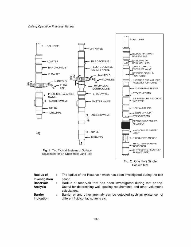
192
Drilling Operation Practices Manual
DRILL PIPE
HOLLOW PIN IMPACTREVERSE SUB
DRILL PIPE ORDRILL COLLARS
DUAL CLOSED INPRESSURE VALVE
REVERSE CIRCULA-TION PORTS
HANDLING SUB A CHOKEASSEMBLY (OPTIONAL)
HYDROSPRING TESTER
BYPASS - PORTS
B.T. PRESSURE RECORDED(A.P. TYPE)
HYDRAULIC JAR
V R SAFETY JOINT
BY-PASS PORTS
EXPAND SHOE PACKERASSEMBLY
FLUSH JOINT ANCHOR
HT 500 TEMPERATURERECORDER
ANCHOR PIPE SAFETYJOINT
BT PRESSURE RECORDER(BLANKED OFF)
LIFT NIPPLE
BAR DROP SUB
REMOTE CONTROLSAFETY VALVE
MANIFOLD
FLOWLINE
HYDRAULICCONTROL LINE
LT-20 SWIVEL
MASTER VALVE
ACCESS VALVE
NIPPLE
DRILL PIPE
NIPPLE
DRILL PIPE
MASTER VALVE
MANIFOLD
FLOW LINE
DRILL PIPE
BAR DROP SUB
ADAPTER
FLOW TEE
PRESSURE BALANCEDSWIVEL
(a)
Fig. 2. One Hole SinglePacker Test
Fig. 1 Two Typical Systems of SurfaceEquipment for an Open Hole Land Test
Radius of : The radius of the Reservoir which has been investigated during the testInvestigation period.Reservoir : Radius of reservoir that has been investigated during test period.Analysis Useful for determining well spacing requirements and other volumetric
calculations.Barrier : Barrier or any other anomaly can be detected such as existence ofIndication different fluid contacts, faults etc.

193
Drill Stem Testing
Fising NeckChoke
Circulating Valve Cup
Locking Mechanism
Testing Valve
BT PressureRecorders
Bypass Valve
RTTS Packer
RUNNING IN OPEN FOR TAKING OPEN FOR SUBSEQUENT REVERSING TREATINGTEST FIRST TEST C.I.P. RETRIEVABLE FOR
C.I.P. VALVE SQUEEZING
Fig. 3: Hydrospring Retrievable Valve Tester

194
Drilling Operation Practices Manual
Diagrams
(b) EXTRAPOLATION OF PRESSURE BUILD-UP CURVES INDICATING A BARRIER
Fig. 4
Above Packer B.T. Blanked-Off B.T.
(a) PRESSURE RECORDER CHARTS SHOWING A BARRIER
291
537
TIC
KE
T N
O.
B.T
GA
UG
E N
O.
I
NIT
IAL
FIN
AL
EX
TRA
PO
LATI
ON
PR
ES
SU
RE
GR
AP
H

195
Drill Stem Testing
Fig. 5 components of the unitest tree
Two of the ways of making up the Unitest Treesurface control equipment are as follows :
(from Top to Bottom)(1) (2)A BC ED GF HHI
A - Lift Nipple
C - Bar Drop SubB - Adapter
D - Bar Drop Sub
E - Remote Control Valve
F - Pressure Balanced Swivel
G - LT - 20 Swivel
H - Master Valve
I - Quick Disconnect
H - Master Valve
S-15 ManifoldFlo-Thru Manifold
is not shown

196
Drilling Operation Practices Manual
CHAPTER - 16CORING
The 60 feet core barrel consists of two sections- (a) Upper sections & (b) lower sections (fig-2).The upper section contains safety joint with an API box connection, swivel assembly and top stabilizer,the bottom section of barrel have two stabilizers and an elevator sub at top, core head pin connectionand core catcher at lower end.
16.1 CORE BARREL ASSEMBLING• Before picking up barrel sections ensure that all outer tube connections are sufficiently tight
to prevent backing out in the derrick while assembling.• Pick up lower section (fig. 2b) and tighten thread connections to the recommended torque
using rig tongs and rope on cathead and lower in the rotary table. Avoid setting slips orplacing tongs on box connections (fig. 3).Note: Bottom Protector must be tight.
• After making middle stabilizer place drill collarclamp above slips, below middle stabilizer.
• Back out elevator sub from outer tube using chaintongs.
• With inner tube still connected to the elevator sub.Pick up inner tube approx. 6-9 inches.
• Make up inner barrel clamp to the inner barrelleaving sufficient space above on inner barrel boxconnections (fig. 4).
• Back out elevator sub taking care not to damageinner tube connection.
• Place core barrel inner and outer tube protectorson elevator sub. Make up API connection turningthe sub upside down on elevator sub to connectionon the top section of core barrel.
• Pick up upper section in elevators.• Remove bottom protector, exposing inner barrel.• Remove inner tube thread protector.• Make up upper and lower sections of inner barrel.
Tighten with chain tongs using cheater bars.• Pick up on elevators and remove inner tube clamp.• Make up outer tube connections using chain tongs.• Finally tighten to recommended torque with rig
tongs.• Lower core barrel, torque up top stabilizer and
safety joint cross over sub above stabilizer.• Reset slips as near as possible to top stabilizer,
allowing sufficient space for drill collar clamp.• Back out safety joint using chain tongs, remove
inner barrel from outer.• Check core catcher is present. Also ensure core marker is present.

197
Coring
• Tighten inner tube shoe lower and upper halves using chain tongs and cheater bars.• Run inner barrel back into outer tightening middle connection, top connection (at swivel
assembly) and all connections on swivel assembly.• Make up safety joint fairly tight.• Pull assembled barrel out of the rotary table.• Break off bottom protector and check lead.(fig. 5,6,7)• For adding or removing shims, run barrel back into rotary table .Set slips below top stabilizer,
make up collar clamp and back out safety joint, pick up until 8 inches of inner tube isexposed. Put inner tube clamp on inner barrel. Back out cartridge cap and add or removeshims as necessary.(fig. 8)
• Once spacing is corrected, pick up, remove inner tube clamp and make up safety joint withchain tongs.
• Torque safety joint to recommended torque with rig tongs.• Pull barrel out of rotary table, take off protector and check lead using CB gauge.• Make up core head.• Check rotation of the inner tube.• Run core barrel back into rotary table.• Set slips below blades of top stabilizers.• Ensure steel ball is not in ball seat.• Pick up required cross over or drill collar and make up to API torque rating.
Barrel is now ready to be lowered.
16.2 CORING PROCEDURE
Preparation• On the last bit run prior to coring, run the junk sub to clean the hole from any junk. Incase of
doubt run reverse circulation basket or magnet to ensure complete removal of junk from bottom.• In case of dog legs, tight spots etc. in open hole, circulate the hole thoroughly and make
wiper trip before coring to avoid sticking of core barrel.• Select core head based on previous experience, bit records and formations to be drilled.• Check core barrel connections with drill collar for its compatibility. If not ensure cross over is
available.• Ensure availability of adequate number of drill collars for giving sufficient weight.• Run adequate number of stabilizers to keep core head steady on bottom.• Volume of mud to be circulated will be determined by mud type, depth of hole, pumps and
type of formations drilled.• Avoid mixing LCM in large quantities which could possibly block core barrel or core head fluid
passage.• When starting coring, a slow rotary speed of 40-50 should be applied and gradually it can be
increased. In general a rotary speed of 70-120 RPM is sufficient to core most formations.• Weight on bit will be determined by size of bit, size of core barrel and nature of formation to
be cored. When starting coring apply minimum weight and then increase in small increment(1-2 Ton) until optimum performance is achieved. Do not use more than recommended weighton bit for the specific core barrel.
• Use correct combination of weight and rotary speed to avoid excessive or fluctuating torque.• Ensure that there is no restriction in the string to stop passage of pressure relief plug ball.

198
Drilling Operation Practices Manual
• Check pump liners and stroke for desired flow rate.• On reaching bottom make up Kelly and start circulation
with recommended flow rate (note down pressure) at least one single before drilled depth.• Abnormally high pump pressure indicates that there may be debris in the barrel or core
catcher and it should be cleared before starting coring.• Wash down to bottom and watch for tight spots.• Tag bottom and mark Kelly.• Lift 2-3 feet off bottom, circulate for 5-10 minutes.• Run back to bottom and check Kelly measurement.• Wash down slowly picking up periodically and checking Kelly measurements with pipe tally.• When true bottom is reached a WOB gain accompanied by a pressure increase will be
noticed.
Figure 8

199
Coring
• Once bottom is reached circulate for another 10-15 minutes to clean out inner core barrel.• Pick up, break off Kelly and drop steel ball, add spacer sub, if necessary.• Make up Kelly. Start circulation, again note circulating pressure.• Pump ball to bottom, when ball seats on pressure relief plug a slight pressure increase will
be indicated.• Record final off bottom pressure with ball seated.
16.3 CORING OPERATION• Check pump strokes to ensure correct circulation rate is delivered to core head.• Lower barrel until minimum starting weight is reached.• Start rotary and bring it slowly to 40-50 RPM.• When bit has touched bottom maintain starting weight till one foot has been cored.• Then increase the weight slowly in 2000 lbs. increments.• Increase rotary speed to approx. 60 RPM.• When two to three feet has been Cored, weight and RPM can be varied to achieve maximum
performance.• Record pressure and maintain it throughout the coring. If there are large variations, it should
be immediately analyzed and corrective action should be taken.
16.3.1 Possible Causes of Pump Pressure ChangePressure change could be due to changes in flow rate, debris in pump valve seats or washed
liner. First check pumps strokes and condition.• Pressure decrease could be due to core jamming or filling of core barrel. Or it may be due to
wash out in drill string. Then pull out of hole.• If pressure increases then either bit has been damaged (If on lifting bit off bottom the pressure
returns to normal and on retagging bottom it increases immediately then bit is damaged) ordue to inner barrel or swivel assembly backing out and sitting in core head. It can be found bylifting string off bottom as in this case most likely pressure will remain high.
• Minor fluctuations in pressure can be due to changes in formation, while mud is being mixedor unbalanced mud in hole after a trip.
16.4 CORE BREAKINGStop rotary table and shut off pump. Mark the Kelly.• Pick up Kelly until weight indicator shows core has been caught, continue picking until core
breaks (this will be indicated by reduction in string weight – with a sharp reduction in stringweight once core is broken) or an over pull of 20000 lbs. is reached. If core does not break atthis point then circulate at normal coring flow rate, maintaining pull until core breaks.
• Pick up approximately 10 feet, then lower slowly back to one feet off bottom, watch theweight indicator, making sure that barrel goes back to bottom without meeting any obstructioncaused by core left in hole.
• To resume coring after connection, run to bottom without rotary or circulation and add approx.50% higher than normal coring weight. This additional weight will release the core from thecore spring, permitting the passage of new core into the core barrel.
• Lift the drill string until normal coring weight is reached. Start pump at normal rate. Bringrotary up slowly to normal rotation and continue to core.
• Ensure that pump pressures are normal when coring recommences.
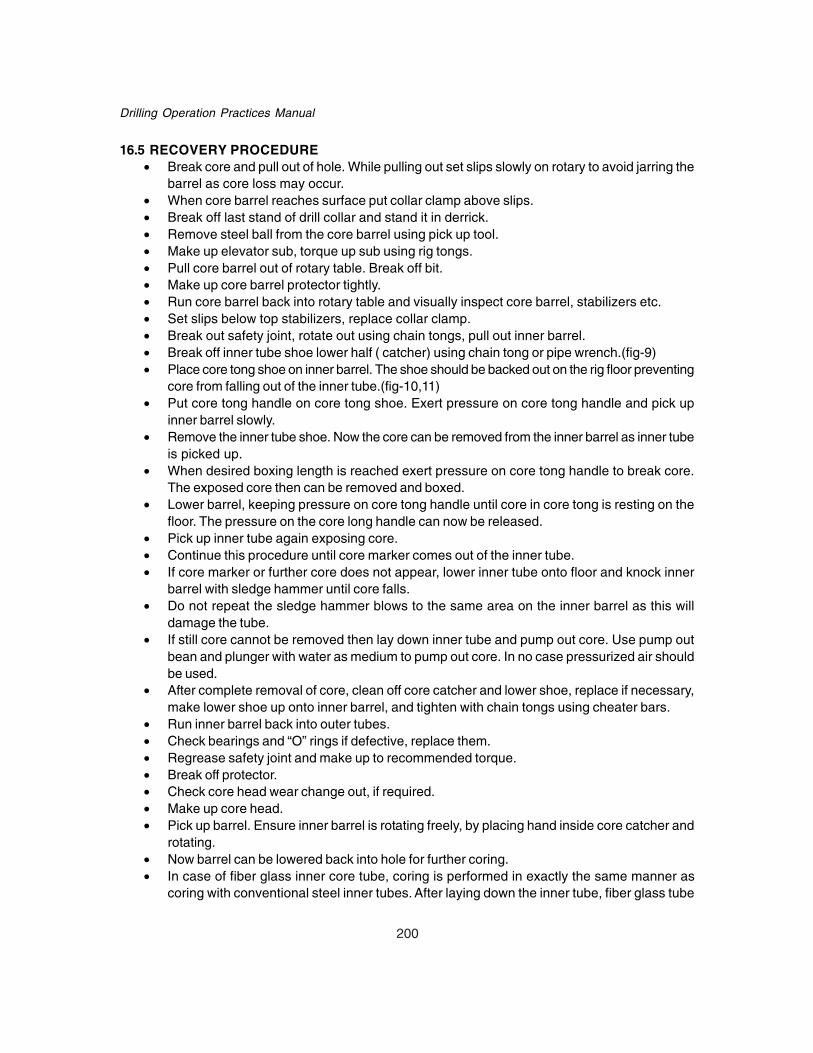
200
Drilling Operation Practices Manual
16.5 RECOVERY PROCEDURE• Break core and pull out of hole. While pulling out set slips slowly on rotary to avoid jarring the
barrel as core loss may occur.• When core barrel reaches surface put collar clamp above slips.• Break off last stand of drill collar and stand it in derrick.• Remove steel ball from the core barrel using pick up tool.• Make up elevator sub, torque up sub using rig tongs.• Pull core barrel out of rotary table. Break off bit.• Make up core barrel protector tightly.• Run core barrel back into rotary table and visually inspect core barrel, stabilizers etc.• Set slips below top stabilizers, replace collar clamp.• Break out safety joint, rotate out using chain tongs, pull out inner barrel.• Break off inner tube shoe lower half ( catcher) using chain tong or pipe wrench.(fig-9)• Place core tong shoe on inner barrel. The shoe should be backed out on the rig floor preventing
core from falling out of the inner tube.(fig-10,11)• Put core tong handle on core tong shoe. Exert pressure on core tong handle and pick up
inner barrel slowly.• Remove the inner tube shoe. Now the core can be removed from the inner barrel as inner tube
is picked up.• When desired boxing length is reached exert pressure on core tong handle to break core.
The exposed core then can be removed and boxed.• Lower barrel, keeping pressure on core tong handle until core in core tong is resting on the
floor. The pressure on the core long handle can now be released.• Pick up inner tube again exposing core.• Continue this procedure until core marker comes out of the inner tube.• If core marker or further core does not appear, lower inner tube onto floor and knock inner
barrel with sledge hammer until core falls.• Do not repeat the sledge hammer blows to the same area on the inner barrel as this will
damage the tube.• If still core cannot be removed then lay down inner tube and pump out core. Use pump out
bean and plunger with water as medium to pump out core. In no case pressurized air shouldbe used.
• After complete removal of core, clean off core catcher and lower shoe, replace if necessary,make lower shoe up onto inner barrel, and tighten with chain tongs using cheater bars.
• Run inner barrel back into outer tubes.• Check bearings and “O” rings if defective, replace them.• Regrease safety joint and make up to recommended torque.• Break off protector.• Check core head wear change out, if required.• Make up core head.• Pick up barrel. Ensure inner barrel is rotating freely, by placing hand inside core catcher and
rotating.• Now barrel can be lowered back into hole for further coring.• In case of fiber glass inner core tube, coring is performed in exactly the same manner as
coring with conventional steel inner tubes. After laying down the inner tube, fiber glass tube

201
Coring
can be cut into sections at the rig and then sealed with plastic caps at end and sent to lab fortesting.
• In fiberglass inner tube pin threads are molded on both the upper and lower ends which willaccommodate internal flush connections.
• Available sizes for fiber glass inner tube are- 6-3 / 4" x 3", 6 – 3 / 4 “ x 4“, and 8” x 5 1 / 4“
Precautions while coring• Inspect the coring equipment thoroughly (e.g. core catchers, core barrel, bearing, swivel
assembly etc.) for straightness before starting coring.• The hole should be free of junk at the bottom otherwise it will result in worn out diamond core
head.• Avoid reaming with core bit through tight zones while running in.• Avoid drilling with roller core heads as there is no provision for efficient cleaning as in jet bits.• Tight pulls while pulling out and the attendant rotations, jerks and reciprocations to release it,
should be avoided as it may cause the core to slip down.• Try to prevent drill string vibrations while coring.• Unless the coring is complete or otherwise warranted by bad condition of hole, the bit should
not be lifted off-bottom.• Adhere to uniform feeding of WOB for better core recovery.• Breaking off the core should be done as per the norm.

202
Drilling Operation Practices Manual
16.6 CHECK LIST FOR CORING OPERATION• Check the core barrel for crookedness, worn out threads, severe dents etc.• Check the core catcher for defects.• Check the vent valve and if the ball or seat is worn out, replace it.• While making up the complete core barrel assembly, check looking from one end, whether
the same is straight or bent.• Check the roller cutter head for rollers and worn teeth.• During round trip, before coring, check the condition of hole for any tight pull.• If there is any junk in the hole, fish it out before starting coring operation.• Check the Kelly and drill pipe stand for crookedness.• Check mast centering if it is not proper it may cause drill string vibration while coring.
16.7 CORE BARREL SERVICINGAfter the initial make up of the core barrel, it should be checked at regular intervals for wear of
thrust bearings, bearing retainer cartridge cap and plug, “O” rings, pressure relief plug, inner tubeshoes upper and lower, and core springs.
A. Swivel Assembly-1. Replacement Of Thrust Bearings-
• After every core check for bearing wear.• Rotate inner barrel at inner tube plug, if rotation is difficult or rough it indicates that balls
have broken.• Secondly check for vertical movement .If excessive this also indicates worn bearing and
should be changed.• Even after changing bearing if vertical movement exists then check wear on bearing
retainer, cartridge plug and cartridge cap.• To save rig time and loss of core it is suggested to change bearings after 3-4 cores.
2. Changing Bearing (fig- 14, 15)• Break out safety joint.• Pick up inner tube; place inner tube clamp on inner tube as shown.• Using spanner wrench back out cartridge plug.• Pick up safety joint exposing bearing and bearing retainer.• Before breaking out bearing retainer place rags etc around slips to prevent balls dropping
back into hole.• Back out bearing retainer and change bearing .• Clean and dope retainer, hammer up.• Clean and re dope all threads and make up cartridge plug ensuring it is tight.
B. Changing Pressure Relief Plug (fig-16,17)• Set inner tube clamp as shown.• Break out inner tube plug.• Break out pressure relief plug. Lay safety joint on floor to do this.• Check ball seals and change out, if necessary.• Clean and dope all threads and make up inner tube plug.
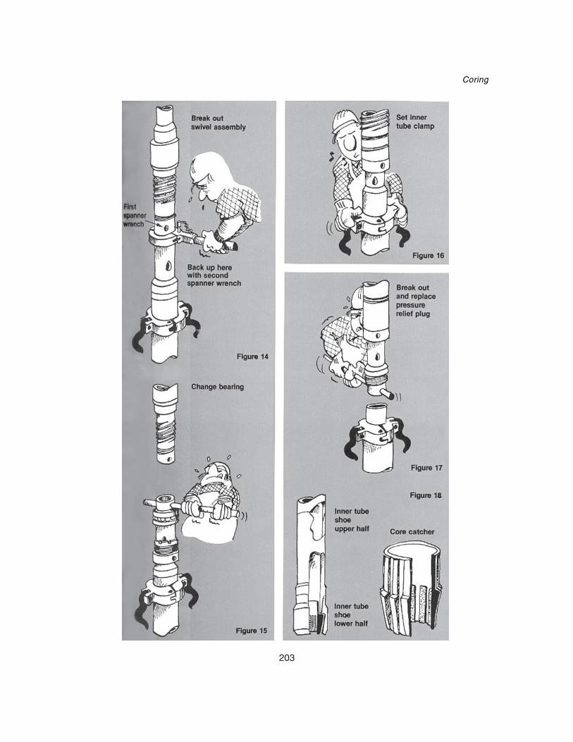
203
Coring

204
Drilling Operation Practices Manual
C. Safety Joint
i) “ O” RINGS• Check condition of “O” rings regularly and change them when they are damaged.• “O” rings can be changed while changing bearing or after core recovery by sliding them
up while inner barrel is being lowered back into outer barrel.
ii) FRICTION RINGS• Ensure that friction ring is free moving, clean it with diesel if it becomes clogged up.
D. Inner Tube Shoes (Upper & Lower) and Core Catchers (fig-18)• Check threads on inner tube shoes and general condition at every core- change if required.• Ensure that core spring is in good condition.• Make sure that tungsten grit has not been worn flat.
DO’S AND DON’TS• Inner core barrel should be always be coated with chain oil before laying down.• Keep circulation rate around 16-19 lt/ sec. for coring – which is an optimum flow rate.• Make up all joints of inner barrel using chain tong only and check inner tube threads.• Check vertical play in bearing. It should be less than ¼” .• Check swivel joint for free rotation.• Check length or inner tube shoe lip, from bottom of outer tube sub with the help of gauge
supplied.• Keep the steel ball outside while running the core barrel into the hole.• Circulate one foot off bottom at least for half an hour for cleaning bottom before starting coring
operation.• Do not change the bearing on rotary as the steel balls of thrust bearings may fall into the hole.• Do not run in the core barrel without adjusting shims in case the length of the inner tube shoe
lip below outer tube sub is not as per recommendations .It may affect core recovery.• Do not push the core head down through tight spots. Ream if necessary.• Do not keep barrel in hole if appreciable decrease in penetration rate is noticed.• After core recovery do not keep the core marker out side. It should be kept inside the core
tube.• Do not forget to crack all joints of core barrel before laying down.
16.9 RECOMMENDED MAKE UP TORQUE FOR “CHRISTENSEN CORE BARREL”
SR.NO. CORE BARREL SIZE RECOMM. MAKE UP TORQUE MAXIMUM PULL(FT.LBS.) (LBS.)
1 4 – 1 / 8 “ 3,00 101, 400
2 4 – 1 / 2 “ 5,00 194, 700
3 4 – 3 / 4 “ 5,00 137, 400
4 5 – 3 / 4 “ 7,00 183, 000
5 6 – 1 / 4 “ X 3” 15,000 290, 000
6 6 – 1 / 4 “ X 4 “ 8,000 193, 500
7 6 – 3 / 4 “ 9,500 275, 000
8 8 “ 20,000 322, 000

205
Directional Drilling
CHAPTER - 17DIRECTIONAL DRILLING
Directional Drilling is usually accomplished (at shower depth) by jetting using a jet bit with onelarge size nozzle and two blinds or by a mud motor with a bent sub or an adjustable bent housing,depending on the type of formation to be drilled.
Prior to the start of any directional well a pre spud meeting should be conducted. The directionaldrilling plan for the well should be discussed and following topics should be included:
• Wells that may be approached during the course of drilling a directional well to avoid collision.• Directional drilling procedures and surveying requirement that will be used to maintain
adequate well to well separation.• HSE issues regarding the survey winch etc.
It must be verified that all personnel directly involved with carrying out the directional drillingoperation are aware of all important aspects of the operation. This is especially critical following acrew or tour change. In this regard a brief report regarding the well being drilled and behavior of thewell may be handed over to directional driller to help the reliever to take quick and correct decisionimmediately after reaching the site.
17.1 RESPONSIBILITIES
17.1.1 Directional Driller
The Directional Driller is responsible for drilling the well and performing directional surveycalculations, proximity checks and ensuring that correct survey correction factors are applied toeach survey in accordance with well programme requirements. He is to liaise with all responsiblepersonnel during drilling operation.
The Directional Driller is also responsible for The BHA to be run into the hole is given by directionaldriller. The Driller and Directional Driller are responsible for the dimensional inspection of the BHA.Directional driller may be called on the rig floor whenever a BHA is made to be run in the well. Itmust be ensured that BHA has the correct length of non-magnetic components to prevent magneticinterference while using magnetic survey instruments.
The gauge of bit to be run into the hole and integrity of nozzles should also be checked.
17.1.2 Tool Pusher / DIC• Directional driller must be called on the rig sufficiently before the kick off operation begins.• Directional driller must be informed before any pull out of the hole is made due to any reason
to avoid any extra trip for change of the BHA which may be required during next run.• The bit change program must be discussed with directional driller so that it can be clubbed
with BHA change program if possible.
17.1.3 Driller/Assistant Driller
Drilling parameter given by directional driller during the course of drilling a well must be strictlyfollowed to avoid any extra trip for the control of well path. He must help the directional driller inmaking survey barrels and in lowering it into and pulling out of the hole.
Directional Driller must be called on rig floor when the required survey depth is reached.
206
Drilling Operation Practices Manual
17.2 DEVIATION CONTROL
Causes of hole deviation1. Formation properties2. Improper mechanical arrangements of bottom hole assembly.
Drilling a straight hole• Drill with packed hole assembly i.e. drill with stabilizer above the bit and stabilizers in the
string (given in tables later).• To avoid angle build up when using a near bit stabilizer place the near bit stabilizer
immediately above the bit and place a string stabilizer 10 to 30 feet above the near-bitstabilizer. A third stabilizer at a distance of 30 feet from the second stabilizer may also beused which gives still better results.
If Angle Builds due to dipping formations• Restrict the rate of angle build with a packed BHA.• Before maximum permissible limit of inclination is reached (normally 3o-5o), drop angle by
changing the BHA to a pendulum BHA and continue drill with reduced weight on the bit.• Drill 40-50 metres.• Ensure the angle drop by survey.• If clear trends are observed continue drilling with desired drilling parameters till the required
inclination is reached.• If inclination does not drop, use high rotary speed with reduced WOB to enhance pendulum
effect.
17.2.2 Precautions• At least two sets of survey instruments should be available on rig.• Ensure both the sets are functional by using them regularly.• Reaming is acceptable to reduce angle but to avoid unscrewing the drill pipe due to doglegs
higher in the hole., the following should be taken care of :Use minimum BHA required.Do not stop rotary abruptly, slow down gradually before stopping.Use rotary brake to stop backlash.Dogleg should be worked out as per well plan.Don’t use dull bits as these contribute to an increase in hole angle in crooked holeformations.On floaters, deviation in 36” hole should not exceed 1-1/2 degrees.Use of “average angle” directional survey calculation method in the field is acceptable.However, the “radius of curvature” or “minimum curvature” method should be used toprepare the final directional report.
17.3 DIRECTIONAL DRILLING AIDS
17.3.1 Stabilizers1. All the stabilizers should be full gauge. However a slightly under gauge stabilizer (up to 1/
8” or lesser) at 90 ft. or higher) may be considered as full as gauge.

207
Directional Drilling
2. Stabilizers should be gauged in each round trip
3. As a rule, cement drilling inside casing should be done with slick assembly.4. Stabilizer should have either:
Open design (Vertical Holes) - 3 blades having a wall contact of + 1400.or
Closed Design (Deviated Holes) - 3 blades having wall contact of 360o.
5. If the formation have tendency to develop key seats, a stabilizer having 360o wall contactplaced at the top of collars is often helpful.
6. The bottom 90 feet of BHA should be appropriately stabilized for proper control in adirectional hole.
7. Integral blade near bit stabilizer is preferred during jetting.8. Stabilizers should have A Brinell hardness between 300 and 321.
9. The inside diameter of the stabilizer should preferably be the same as the inside diameterof the drill collar string.
10. Preferably the near bit stabilizer should have a box down to avoid cross over.
Precautions
1. Stabilizers are often the source of high torque. Generally torque developed by stabilizerswill fluctuate widely.The common practices of controlling torque are:a. Use more number of heavy weight drill pipes and accordingly reduce No. of drill collars.b. Use non-rotating blade (rubber) stabilizers. These stabilizers are generally acceptable
for straight holes, but have a short life span in some formations.c. Reduction in rotary speed &WOB to control torque is not recommended.d. Condition the drilling fluid to have high lubricity & low solids.
2. Restrict the drilling torque to less than the make-up torque applied to the weakest connectionin the drill string.
3. Torque developed by extremely large hang-down weight below a dogleg or kick-off pointcan be reduced by:a. Using a full string of smaller drill pipe (e.g. using a 4-1/2:” O.D. drill pipe to replace 5”
O.D. Drill pipe.)b. Using a smaller string on bottom (tapered string).c. Using an oil base mud when conditions are severe.
The torque meter on any rig should be calibrated at least once per well.
17.3.2 PreplanSlot selection for a particular well should be done according to the target direction of the well.• Wells which require more drift or inclination should be allotted outer slots and those with
lesser drift the inner slots.• It is also important to see the direction of the well. Slot should be selected so that the
distance between the well increases as they are drilled.• Central slot may be selected for vertical well.

208
Drilling Operation Practices Manual
17.3.3 Kop Selection Procedures• On Offshore platforms if most of the wells have approximately same drift in different
directions their KOPs must be varied at least by 10 or 20 m to give the wells some initialseparation to avoid collision of the wells directly underneath the platform.
• KOP must be selected in relatively softer formations.• KOP selection for a given well also depends on the TVD and drift of the well and directional
technique used. KOP must be selected so that the angle required to hit the target is atleast 20o or more.
17.3.4 Checking of Instruments/Equipments• Functioning of all single shot & multishot instruments.• Functioning of survey winch and its proper grouting for on land operation.• Functioning of sand line• Availability of down hole motors, NMDC, UBHO, stabilizers, stabilizer sleeves, short drill
collars, bent subs, HWDPs and other required subs.
17.3.5 Procedure for Muleshoe (UBHO) Sub Sleeve Alignment1. Lower the deflection tool (Jet bit/Mud motor bent sub assembly) and the Muleshoe sub
through the rotary table.2. Set the slips keeping the set screws of UBHO sub above the slips.3. Back off the Monell drill collar above the UBHO sub.4. Loosen the set screws in the UBHO sub.5. Align the key of the UBHO sub with projected scribe line of bent sub or open jet and
tighten the set screws of UBHO.6. Check the Muleshoe sleeve with key alignment wrench by rotating it in either direction to
ensure that sleeve doesn’t slip.
Orientation Procedure1. When the kick off point (KOP) has been reached, conducting a multishot survey is preferred
to determine the condition of the well bore from surface to kick off point.2. Once the bit reaches bottom directional survey should be conducted to ascertain the
tool face.3. Based on directional survey orient the tool face in the desired direction.4. Take a check shot survey to confirm tool face setting.
17.3.6 Positioning Compass in the Nonmagnetic Drill Collar• Select the length of NMDC & decide positioning of compass using standard guide lines.• Use extension bars in the lower section of survey barrel to space compass in NMDC.• Do not consider the length of muleshoe stinger for deciding the position of compass in
NMDC.• Orienting snubber is 9” long, so add this 9”to extension bar length for calculating the position
of compass.

209
Directional Drilling
Alignment of the scribe line on the compass face with the keyway of the Mule Shoe StingerAfter determining the appropriate length of extension bar, connect the mule shoe stinger to
the lower end of it and connect the orienting snubber to the upper end. Align the scribe line as
follows:
1. Project a vertical line from the top of the keyway, up the lower extension bar, to the T-headof the orienting snubber.
2. Loosen the set screws of T-head of the orienting snubber.
3. Align the T-head and the compass face with the projected line from the top of the keywayso that the scribe line 180o away from the keyway.
4. Tighten the set screws
Insertion of Tattle tale (Lead Pin) into the Mule Shoe StingerBefore survey barrel is lowered into the drill string a tattle tale (Lead Pin) is inserted into the
hole at the top of Keyway of Mule shoe stinger to make sure that blade /key of the mule sub hasreached the key way. After survey barrel is retrieved the tattle tale should be bent or crushed.
17.4 RECORDING OF SINGLE SHOT SURVEY1. Load the single-shot instrument2. Set the mechanical clock and synchronize the surface watch or use monel sensor in survey
instruments. Check it with monel ring on surface.3. Put the single-shot instrument onto the T-head of the oriented snubber.4. Insert the single-shot instrument into the protective casing.5. Connect the protective casing and survey barrel and tighten the same with wrench.6. Always use drill pipe thread protector before lowering the survey barrel into the drill string.7. Lower the Survey barrel assembly inside the drill string through wire line /sand line to take
survey.
Rubber guide fingers must be inserted into the holes of mule shoe stringer/bottom shockabsorber and finger guide holder installed above the protective casing.
• Once kick off operation is over normally a packed hole assembly is used. For this anothersurvey barrel is used. The required length of the extension bar must be calculated usingcharts.
• Use internal shock absorber in place of orienting snubber and bottom shock absorber inplace of mule shoe stringer.
• Mule shoe sub is removed and a baffle plate is put below the non magnetic drill collar. Ashort piece of pipe (OD equal or slightly lesser that OD of Drill collar) may be welded atthe centre of the baffle plate. It will prevent the baffle plate from tilting when survey barrelsits on it.
17.4.1 Reading of Single Shot Survey
a) Holding the reader1. The reader must be held in such a way so that the arrow which indicates hole direction
points up.

210
Drilling Operation Practices Manual
2. When held correctly, the word “left” should appear on your right-hand side, and the word“right” should appear on your left-hand side. It is because when a picture is taken of theface of the compass during survey, it results in a reverse image. In order to correct for thisreverse image, left and right are reversed on the reader.
b) Placing the single shot record on the reader1. The hole direction line on the reader passes through the center of the concentric circle and
through the center of the crosshairs on the survey record.2. The number and letters on the survey record are oriented in the proper fashion. The numbers
1 through 8 between the N and W are in forward order and while moving towards right onthe picture i.e. towards right or East of N North) the numbers are in reversed order as shownin fig. below.
c) Reading single shot survey1. Read number of concentric circle/ curved line under the cross hair to indicate the inclination
of the hole with the least count of 1/40.
2. Read the position of the straight line under the hole direction line on the reader to indicatethe direction of the hole with the least count of 1/20..
3. Read the position of the long line of the cross hair on the edge of the reader in degreeswith respect to left or right to indicate T.F. (Tool face) with respect to hole direction.
4. Orient the tool face in desired direction.
d) Procedure for determining toolface
1. Place the survey record in the reader correctly.
2. Read drift angle and hole direction in the usual manner.
3. Take the reading long line of cross hair from the edge of the reader on left or right sideasthe case may be. This will indicate tool face in degree left or right of hole direction.

211
Directional Drilling
Example: (refer fig. given above)Details as read from above figure:
Inclination Direction Tool face4-1/4o N17oW 115o R
R denotes right side. Tool face is 115o right of hole direction N17oW or tool face in S82oE direction.
e) Correction of magnetic declinationMagnetic Survey which is read by the reader must be corrected for declination (East or Westavailable from geological office.
Methods for applying correction for East/West declination1. For East declination rotate the observed direction in clock wise direction by an amount
equal to degrees of east declination and find the corrected direction.2. For west declination rotate the observed magnetic direction in counterclockwise direction
by an amount equal to degrees of west declination and the corrected direction.
17.4.2 Survey Calculation MethodThough minimum curvature method gives most accurate results, average angle method may be
used in field because it is easier to calculate survey data by this method using scientific calculatorand it generates fairly accurate results.
Note : When kick off is done by a mud motor, assembly is pulled out of hole even if maximumangle may not be achieved after the desired direction has been achieved. After this, build up isdone by using a near bit full gauge stabilizer into the string.
Rotary assemblies normally have right walking tendency. It is therefore, recommended that beforethe kick off assembly is pulled out of the hole, the direction of the well should be kept slightlytowards the left depending upon the field behavior.
Sometimes well may travel towards left due to formation characteristics, in such cases thewell direction is kept slightly towards right.
17.5 DRILLING WITH MUD MOTOR
For proper working of mud motor care should be taken regarding mud properties.Following pointsshould be considered:
1. Sand and solid contents should not be more than 2% by volume or as indicated by themanufacturer. So desilters should be continuously used while drilling with a mud motor.
2. Rags etc. accidentally dropped down the system into the circulating system can plug anddamage the motor. Always use a mud filter below the Kelly.
3. The elastometers of PDM gets damaged when oil based mud is used.4. Operationally PDM has a working limit of bottom hole temp. upto 275oF.5. The mud motor is designed to handle lost circulation materials but particle size should not
exceed the recommendation of the manufacturer.
17.5.1 Operational checks1. Lifting sub should be used for picking up motor.

212
Drilling Operation Practices Manual
2. Check axial play of the bearings.
3. Hang the motor freely and measure the distance between the lower end of bearing housingand drive sub as X1.
4. Rest the PDM down on the rig floor and measure the same distance as X2.
5. Calculate (X1-X2). It should be within limits as tabulated below:
Tool Size Allowable Max.play(diameter in Inches) (X1 - X2) in mm.
1 ¾ 1.3
2 3/8 1.7
2¾ 2.5
3¾ 4
4¾ 4
6 ¼ 6
6¾ 6
8 8
91/2 8
11 -1/4 8
6. Set the mud motor in rotary table, using safety clamp.7. Check dump valve for its easy operation using wooden handle of hammer.It should be free.8. Test the mud Motor by connecting kelly. Test should not be performed for more than 15
minutes.
17.5.2 Drilling
Generally a string with a PDM can be run into the hole like a standard bottom hole assembly.When a deflection device (Bent sub) assembly is used, special care must be taken when passingthe well head, casing shoe, liner hanger etc.
Note : If reaming becomes necessary when tripping into the hole, extreme care should be taken,especially if diamond bits are used.
When the bottom is reached, the PDM is started as follows:-
• Pick up the bit to a distance of 1 to 2 feet (0.3-0.6 m) off the bottom.• Start the mud pumps and increase the number of strokes to the desired flow rate.• Record the total pump pressure and flow rate.(Off bottom pressure)• After thorough circulation, lower the bit and tag the bottom and increase weight on bit
slowly. After one meter is drilled, increase weight on bit. Pump pressure will rise withincreasing weight on bit. The differential pressure created simultaneously must notexceed values on manufacturer’s recommendations.

213
Directional Drilling
In case of Drilling with PDM stand pipe pressure gauge acts as WOB indicator. Bit weightvariations, formation changes and bit wear will change the torque at the bit. This is indicated by anincrease or decrease in stand pipe pressure. A sudden rise in stand pipe pressure occurs if thePDM stalls. If this happens, pull the bit off bottom. After the pressure decreases, the PDM and bitshould be lowered carefully to the bottom again and drilling is commenced. In order to drill withconstant speed and torque, keep the flow rate and pump pressure at a steady level. Since thespeed of the motor directly depends on the flow rate, the bit RPM will remain constant, as long asthe flow rate is kept constant.
17.5.3 Testing of Mud Motor• A Screen should be used during surface testing• Before starting the pumps it should be ensured that bypass valve ports are below the rotary
table.• Slowly increase the pump speed and note the flow rate & pressure drop across the motor
at which by pass valve closes.• While by pass valve is in closed position, lift the motor above the rotary table until the by
pass is accessible and checked for any leakage from the ports, indicating faulty seals.• Test the motor at different flow rates (at least 3 values) within the expected working rangeand
note down the corresponding pressures. The amount of flow through the bearing shouldalso be noted. A small amount and flow should be through the bearings. A back up lineshould be fitted over the stator during testing at surface to prevent back torque.
• After making allowances for surface equipment pressure losses and mud weight, thepressure should be in accordance with the performance curves.
• Lower the by pass valve below the rotary table before the pumps are shut off.
After testing of the motor, motor assembly can be made up for lowering into the hole. Thepressure drop across the bit nozzles for specified mud discharge should be minimum or as per themanufacture’s recommendation. Minimum back pressure of 500 psi will force the mud to lubricatethe bearings. The pressure drop beyond the maximum recommended pressure may reduce thebearing life.
Precaution• As PDMs will permit circulation only when rotor is rotating, idle circulation for mud
conditioning should be kept to a bare minimum period.• Excessive WOB will stall the motor. Stalling will be indicated by sudden increase in stand
pipe pressure. Lift the motor immediately when pressure shooting is observed.Repeatedstalling damages the elastomers.
• While drilling with PDM a screen should be used below the kelly in the drill pipe. Whenadding next drill pipe this screen should be removed and kept in the new drill pipe which isadded.
• While drilling with mud motor a left hand torque is created on the stator and thereby on thedrill string. This torque must be compensated for orienting the tool face, by an amountequal to reactive torque, more towards right which is actually required to achieve desireddirection.
• Remaining procedure for orientation will be the same as described in orientation procedurewith a jetting bit.
214
Drilling Operation Practices Manual
17.5.4 Trouble ShootingMany common down hole drilling problems can be identified by giving careful attention to mud
pressure variation. Table given below gives some information about identification of the problemand corrective measures to be taken which may save costly additional trips.
Trouble Possible Reasons Actions to be taken
Sudden • Tool Stalls Pull out and replace tool.pressure • Internal tool pluggingincrease foreign bodies
Pressure • Bit plugged Pick up and check pressure. If differential pressureincreasing is higher than starting differential pressure; try toSlowly above clean bit by varying circulation and reciprocate thenormal string. If not successful, pull out.
Change of formation. Pick up and check pressure. If drift pressure equalsstarting drift pressure go ahead.
Slow decrease Circulation loss Pull out for checkof pressure Washout in the drill
string
Decrease in Formation change Try with variations in drilling parameters. ChangeROP WOB, change circulation
Bit worn Pull out for bit change.
Tool stalls / NO ROP Pick up and start again after pressure check, withless WOB.
17.6 BUILD UP ASSEMBLY
Near bit stabilizer is used for building angle in build up section. Near bit stabilizer acts as fulcrumwhich forces the bit up and a reaction force developed on the stabilizer forces the stabilizer tothe low side of the hole So while using a near bit stabilizer assembly for kick off a stabilizer witha sleeve having larger blades or integral stabilizer should be used.
Following points regarding this assembly should be considered
A short Drill Collar is normally added between the bit and the near bit stabilizer. The extensionsub gives extra leverage (side force) below the fulcrum point and accentuates the amount of driftangle increase.
Note : Higher WOB generally causes an increase in angle build rate and decreasing WOB resultsa decrease in angle build rate.
Rule of Thumb regarding right hand walk
In order to slow down the degree of right-hand walk:
• Reduce WOB
• Increase rotary speed

215
Directional Drilling
Second stabilizer
A second stabilizer is added either 30, 60, or 90 feet above the near bit stabilizer. This stabilizerinfluences the amount of bend in the drill collars between it and the near bit stabilizer and thebend in the drill collar causes the fulcrum effect. The shorter the distance between these stabilizers,the lesser the bend created between them. The less bend between the stabilizers produces theless fulcrum effect and thereby the less angle will be built.
1. If the distance is 30 feet approximately 0o-0.75o build per 100 feet. It can be used as holdingassembly.
2. If the distance is 60 feet, you can expect approximately .25 o-1.25 o build per 100 feet.
3. If the distance is 90 feet, you can expect approximately 1.25o to 2o build per 100 feet.
This assembly is also used as angle build assembly.
Drill collar stiffness
A second method to increase the amount of bend between the near bit stabilizer and the secondstabilizer is to change the size of the drill collars.
Weight on bit
Another way to affect the rate of angle build is by changing weight on bit. An increase in weighton bit when using a build up assembly will, generally, cause an increase in the angle build rate. Adecrease in weight on bit will generally, cause decrease in the angle build rate. This occurs becausethe amount of bend in the drill collar between the near bit and second stabilizer will increase ordecrease with an increase or decrease in weight on bit.
There are four variables which control the rate of angle builds up of build up assembly.1. By increasing or decreasing the distance between the near bit stabilizer and the second
stabilizer, you can increase or decrease the amount of bend and the amount of angle build.2. By increasing or decreasing the O.D. of the drill collars, you can decrease or increase the
amount of bend and the amount of angle build will change w.r.t. to amount of bend.3. By increasing or decreasing the amount of weight on bit, you can increase or decrease the
amount of bend and the amount of angle build.4. By increasing the rotary speed the amount of angle build decreases. By decreasing the
rotary speed the amount of angle build increases.
There are four variables which control the rate of angle build up as given below.
0- 30’ Build Up Assembly
EXISTING DRIFT ANGLE WEIGHT ON BIT ESTIMATED BUILD
RATE /100’
MORE THAN 20o 0-15,000 lbs. 0 o - .5 o
15,000-40,000 lbs. .5 -.75 o
LESS THAN 20o 0-15,000 lbs. 0 o -.25 o
15,000-40,000 lbs. .25 o -.50 o

216
Drilling Operation Practices Manual
0- 60’ Build Up Assembly
EXISTING DRIFT ANGLE WEIGHT ON BIT ESTIMATED BUILD
RATE /100’
MORE THAN 20o 0-15,000 lbs. .25 o -.75 o
15,000-40,000 lbs. .5o -1.25 o
LESS THAN 20o 0-15,000 lbs. .25 o -.50 o
15,000-40,000 lbs. .50o -1o
17.7 PENDULUM ASSEMBLIES OR DROPPING ASSEMBLIES
Angle dropping assemblies are based on the pendulum principle.
Pendulum effect results when the near bit stabilizer is removed completely or reduced in size,and the upper stabilizer is retained.
The upper stabilizer holds the drill collar off the low side of the hole providing a pendulumpoint.
Gravity acting on the lower drill collars tends to pull them back towards vertical. The bit isforced to the low side of the hole, and the angle of the hole is decreased.
Points to be considered regarding pendulum assemblies:• As the distance between the bit and the pendulum point increase, the angle drop rate
increases.• As the drill collar thickness increases, the stiffness of the assembly below the pendulum
pointincreases.
• As the existing drift angle increases, the angle drop rate increases.• As weight on bit increases, the angle drop rate decreases.• As rotary speed increases, the angle drop rate increases.
90’ Drop Assembly
EXISTING DRIFT ANGLE WEIGHT ON BIT ESTIMATEDRATE /100’
30 o -45 o 0-15,000 lbs. 2 o -2.5 o
15,000-30,000 lbs. 1.25 o – 1.50 o
20 o -30 o 0-15,000 lbs. 1.25 o – 1.50 o
15,000-30,000 lbs. .75 o – 1 o
5 o -20 o 0-15,000 lbs. .75 o – 1 o
15,000-30,000 lbs .50 o - 0.75 o
0 o - 5 o 0-15,000 lbs. 0 o - 0.50 o
15,000-30,000 lbs 0 o

217
Directional Drilling
60’ Drop Assembly
EXISTING DRIFT ANGLE WEIGHT ON BIT ESTIMATED DROPRATE /100’
30 o -45 o 0-15,000 lbs. 1.25 o
15,000-30,000 lbs. 1.00o
20 o -30 o 0-15,000 lbs. 1.00o
15,000-30,000 lbs. 75 o – 1 o
0 o -20 o 0-15,000 lbs. 0.75 o
15,000-20,000 lbs 0.50 o
30’ Drop Assembly
EXISTING DRIFT ANGLE WEIGHT ON BIT ESTIMATED BUILDRATE /100’
20 o -45 o 0-15,000 lbs. 0.75 o
15,000-30,000 lbs. 0.50o
0o -20 o 0-15,000 lbs. 0.25o
15,000-30,000 lbs. 0.125 o
Packed hole assemblies are used when it is necessary to keep angle and direction change toa minimum. On most directional wells, packed hole assemblies are used after achieving maximumdrift angle to hold inclination.
17.8 RIGHT-HAND WALK AND PACKED HOLE ASSEMBLIES
Packed hole assemblies are designed to minimize right-hand walk, however, some degree ofright-hand walk may still occur when using packed hole assembly.
A commonly accepted method reducing walking tendency is to decrease the weight on bitwhile increasing the rotary speed. If this does not solve the problem, you can change to a stifferpacked hole assembly, or use larger size drill collars to increase stiffness.
An extension sub between near bit stabilizer and the bit in packed hole assemblies inducesthe tendency to build angle slightly. An increase in rotary speed will slow down the build rateespecially if combined with a decrease in weight on bit.
Commonly used packed hole assemblies are:1. 0-10-40-70 assembly.
2. 0-30-60 assembly
17.9 SIDE TRACKINGSide tracking is done to:1. By pass a fish that can not be recovered.2. Correct the crookedness of a hole. If a well has inadvertently gained angle, especially at
shallow depth, it is brought back to vertical with this technique.

218
Drilling Operation Practices Manual
3. Re-drill a hole if the geophysical data indicate missed geological target during the courseof drilling a well
4. Drain hole drilling or multiple hole is also a kind of side tracking operation.
Technique of side tracking
Place a 50-100 mts. long cement plug. The open end d/pipe assembly should preferably havea diverter pipe.
17.9.1 Slurry Design
Sufficient WOC depending upon type of cement & additives should be given before testing thehardness of cement plug. If it does not harden in the given time, give more time or drill out and setanother plug.
1. Put about 10 tons of weight on the plug gradually and take off the weight immediately
thereafter for testing the hardness of cement .
2. Drill About 2-4 mts. of cement top so as to dress down the cement plug top. The plug isto be drilled uniformly at the rate of 5-6 minutes per meter with 3 ton weight on bit, 50RPM andmoderate pump pressure.
Once a sufficiently hard plug top is established, the well is ready for side tracking. Thereafter,drill string assembly is pulled out and kick off assembly lowered.
17.9.2 Time Drilling
Side tracking, through an application of directional drilling technique, requires to be initiated byadopting time drilling process.
Time drilling implies to drill first five meters of interval in a manner so as to permit bent submotor assembly to allow cutting of a wedge. For this the procedure is as under:
1. Reciprocate the assembly about 8 to 9 times. This helps in cutting a groove in the highside of hole.
2. Circulate with both pumps for about 15 minutes just about 15 centimeters above kick offpoint. This will facilitate enlarging the hole right above the KOP which will permit quick takeoff from the cement plug.
3. Drilling parameters are described below:1st mts 40-45 minutes WOB-1/2-1 TON2nd mts. 30-40 minute WOB – 1 ton3rd mts. 25-30 minutes WOB-1-1/2 TON4TH mts. Normal time WOB-1.1/2-2 TON5TH mts. Normal time WOB- 1.1/2-2 TONWOB, should not exceed 2 Ton.
• The time drilling will permit drilling laterally and establishing a shoulder on the side ofthe hole.
• A close watch will have to be kept on the cutting at the shale shaker. The cementcuttings should graduate to formation cuttings by the time first 5 mts. is drilled out.
• If this pinching out of cement cuttings is not observed, next five meters is also tobedrilled with time, otherwise normal drilling is continued hereafter.

219
Cementing Operations
CHAPTER - 18CEMENTING OPERATIONS
18.1 PRIMARY CEMENTATIONThe success of cementing operations can be improved significantly by following the standard
best practices as detailed below. Major factors requiring detailed attention are:• Slurry design / job planning• Blending of cement and additives in bulk handling plant.• Casing lowering, hook up, pre-job arrangement.• Slurry mixing on location, pumping and job execution• Displacement of cement slurry• Job evaluation
18.1.1 Cement Slurry Design and Planning1. Gather the data, obtain and assess all the necessary information prior to preparing any
cement job design and operation programme. The information should include the followingpoints:• Rig, Well No., Field location• Type of job - casing or liner - conventional or sub-sea operation.• Casing sizes, grades, weights and threads.• Casing depths, deviation, hole size, caliper (if available), drilled depth.• Type of mud to be used, mud parameters and rheology.• Bottom Hole Circulating Temperature (BHCT) & Bottom Hole static Temperature (BHST),
expected pore and fracture pressures.• Interested zone intervals with Oil Water Contact (OWC) or Gas Oil Contact (GOC)• Any special well problems (high pressure gas, Lost circulation, salt dome etc.)• Cement rise needed• Any other specific requirement from casing cementation.
2. At job planning stage, the availability of equipment and additives for the job execution shouldbe assessed.
3. Calculate the cementing parameters which include the quantity of cement, total mix water,pump rate, well head and bottom hole pressure during displacement, mixing time, muddisplacement volume, surface pressure and other related information. This will assure thatwell will remain under control during the cementing operation.
4. Design maximum allowable down hole slurry density to prevent fracturing. Slurry densityshould be at least 1 lb/gal (preferable 2 to 3 lb/gal) heavier than the drilling mud.
5. Determine bottom hole circulating temperature (BHCT) from logs and using API Temperaturedata. Temperature logged approximately 24 hrs. after the last circulation ceased can beused as BHST for API table.
6. Design fluid loss as under, as per API testa) For preventing Gas Channeling: Less than 50 ml/30mins.b) For Liner Cementing: Less than 100 ml/30mins.c) For casing cementing: Approx. 250 ml/30mins.
7. Design cement slurry or preflush / spacer to be displaced in turbulent flow to obtain minimum10 mins. contact time at the top of pay zone. Preflush i.e. aqueous solution of dispersantand surfactants are not recommended in high pressure wells.

220
Drilling Operation Practices Manual
8. Weighted buffers i.e. spacers are to be used in high pressure wells and preferably to bedesigned for turbulent flow. The best results are obtained if not only the density but also therheological properties of the spacer fall between those of mud and cement slury. Design thespacer such that it is compatible with both the cement slurry and the drilling mud.
9. If turbulent flow is not possible, then design the job for mud displacement in effective laminarflow using rig pump rate as fast as possible within the limitation of fracture gradient.
10. Use 35% Silica flour (BWOC) at BHST above 230° F (110°C) to prevent strength retrogressionof set cement.
11. For normal slurries, control free water separation to 1.4% or less. To prevent gas channelingand in cementing highly inclined wells, zero free water control should be a primary objective.
12. Determine cement slurry thickening time at BHCT and bottom hole pressure. Minimumthickening time should be job time plus one hour thickening time to a consistency of 50 Bc.Excessive slurry thickening time should be avoided.
13. When field slurries are to be batch mixed, while running the thickening time test in lab,before following API test schedules for increasing temperature and pressures, the slurryshould be stirred in the consistometer at the surface temperature and atmospheric pressurefor the estimated batch mixing and holding time on drill site prior to pumping slurry into thewell.
14. Slurry consistency for all normal turbulent flow slurries should be 10 to 20 BC. Sincesometimes slurries are mixed heavier in the field, so check consistency in the lab for 1 ppgheavier slurry also.
15. Use the same mixing water, cement and additives in Lab testing that will be used on thewells for the job. If additives are dry blended, a blended cement sample must be collectedand tested in the cement test lab before the execution of the job.
16. In the case of certain types of cement jobs, such as long cement column rise or long linerswhere the static temperature at the top of cement is lower than the BHCT, compressivestrength test should be performed at the TOC temperature also to confirm the setting ofcement at the cement top.
18. Compressive strength of set cement stone should be:• 500psi for drill out• 2000psi for perforations
19. In case of primary cementing of gas wells with expected high pressure, special chemicalsneed to be added to cement slurry for effective blockage of gas leakage possibility and theslurry should be tested for its gas tight property in the lab prior to its use in the field.
18.1.2 Blending of Bulk Cement and Additives1. Cement absorbs moisture from its surroundings and changes its properties. Therefore, cement
should be purchased in lot preferably meeting the requirement for 4 months only and storedproperly.
2. Cement additives are used with Oil Well cement (API Class ‘G’) in order to get the desiredproperties of cement slurry as per job requirement. The cement additives are available in dryform or liquid form. Dry chemical powder can be blended with dry cement or can be dissolvedin mix water, whereas liquid additives are to be mixed with water only
3. During blending of dry additives with cement, verify weight calculations, quantity and nameof each additives going into the cement with design composition. Count the additive sacksand cement sacks for each blend.

221
Cementing Operations
4. Visually inspect empty tanks prior to transferring blended materials to ensure that they areempty.
5. To ensure proper blending, transfer the blended material at least twice between silos beforeloading on mobile silos or bulk supply boats for drill site delivery.
6. Conduct fluid loss and thickening time test on samples taken from each container to verifyblending.
7. Transfer dry blend to empty tank and back to original tank just prior to slurry mixing. If extraempty tank is not available on site, then fluff or percolate air through each tank from thebottom for 15-20 minutes to redistribute additives.
8. When different blends are used, each blend and tank should be clearly identified.9. Collect and save sample of each composition for post job analysis if failure occurs. Otherwise,
throw away the samples after the job.10. Check to see that all materials required for job are loaded and identified on the transporting
vehicles. Verify that correct chemicals are loaded with correct weight and volume.
18.1.3 Preparation and Hook-up for Cementing
A. Lowering of casing1. Running in speed of casing should be controlled to prevent fracturing and lost circulation.
Casing lowering should be so regulated that the maximum annular velocity caused by themovement of the pipe does not exceed the annular velocity during normal circulation.
2. Landing joint(s) should be spaced out so the cementing head can be installed from thestabbing board or rig floor after casing is landed.
3. Casing centralisation is a critical parameter that must be part of the cementing programme.Placing of Centralisers should be done with the help of cementing software in order to haveminimum stand-off 67% for deviated wells and near to 100% for vertical wells. Welding ofstop ring on casing and use of welded steel bows should be avoided. Use API approvedcentralizers.
4. Use scratcher against the permeable formation and 200ft. above and below the pay andwater zones in case of casing reciprocation.
5. Use double float protection - a float shoe and a float collar. Check its functioning on surfacebefore make up. Use same type of float collar and float shoe.
6. Put float collar and shoe 2-3 joints apart as depth increases. In case of differential floatequipment, check the size of the ball for actuating them properly.
7. Last two casing joints should be lowered at a very slow speed.
B. Pre-cementation job arrangements1. After arrival at site, calculate the slurry volume required and displacement volume using
actual parameters and also total water requirements including the water needed to flushcementing unit and high pressure lines.
2. Check the mud volume on the site, the hole conditioning, mud rheology, density, flow channelreturn.
3. Ensure that the supply rates of both mud and water required for the job are sufficient foruninterrupted operation.
4. Verify with the rig-in-charge the displacement rates, pressure to apply when plug lands, andhow many barrels (or cubic meters) over the calculated displacement volume will be pumped,if the plug fails to land considering the rig pump efficiency.

222
Drilling Operation Practices Manual
5. In case the displacement is to be performed by the rig pump, the volumetric efficiency ofmud pump, functioning of stroke counter and mud line flow meter should be checked.
6. Conduct a pre hook up meeting to review equipment placement, lay out of high pressurelines, material mixing and pumping sequence, pump rates, slurry densities, safety hazardsduring pumping operation and maximum allowable pressure.
7. Check the air compressor operation, fluff the cement of silos, prime the pumps and mixersprior to the starting of operation.
8. In case of offshore, one has to ensure the proper working of air dryer. If not the entirepneumatic system comprising of compressor, silos, surge tank and lines may get cloggedand free flow of cement will not be there.
9. In case of floater rigs, a mandrel is used for carrying top and bottom plugs. Ensure that thishas been serviced immediately after the last use.
10. Check the cementing head, plug release mechanism, plug dropping indicator and review thenumber and placement of rubber plugs in proper sequence.
11. A detail cementation plan indicating the step by step job sequence duly approved by theconcerned well-site incharges should be made and circulated prior to the operation.
C. Cementing equipment1. Check the cementing units and bunkers to avoid any breakdown during the operations.2. Check the discharge of each cementing unit physically for their capacity in accordance with
the liner size.3. Check the tanks of cementing unit thoroughly, clean if needed.4. Pressure test the cementing head and all connecting lines at 1.5 times the maximum
pressure expected during the job.5. Check and calibrate the pressure gauges.
D. Mud conditioning1. Begin pipe movement and mud conditioning immediately after the casing is lowered. The
casing movement should continue throughout the circulation period. When reciprocating,the pipe is usually moved through a 20ft stroke, using a 2 min. interval for the cycle. Forrotation, the pipe is rotated as slowly as possible, usually between 10 and 15 rpm.
2. Adjust Plastic Viscosity (Pv) and Yield Point (Yp) of the mud to the lowest possible valueswithout dropping solids during mud conditioning.
3. Condition hole with good surface conditioned mud at a rate anticipated for cement pumpingrate for 1.5 to 2 cycles (minimum). For critical jobs such as production casing cementationfresh mud having low rheology may be pumped ahead of cement slurry.
4. Large percentage of annular open hole (at least 90 to 95%) should be “circulatable”, beforethe cement job to achieve the best results.
18.1.4 Job Execution
A. Cement slurry mixing and pumping1. Pressurize bulk units to 15-25psi just prior to starting mixing slurry.2. Start the pumping operation to break circulation to ensure that the casing shoe is open and
check the mud return.3. Do not premix the cement additives in the water more than 5-6 hrs. before the cementing

223
Cementing Operations
job. Before premixing additives in water, better to wait until the final circulation is startedafter casing lowering to the target depth. Verify metering device if liquid additives are premixed in water, continue to agitate chemical water thoroughly until the job is complete.
4. The mix water for cement should be measured through displacement tank because it helpsto calculate easily how much quantity of cement has been pumped in the event of unplannedshutdown. When liquid cement additives are mixed in displacement tanks, measurement ofmixed water is absolutely necessary as tanks are alternately filled and emptied.
5. Control slurry density with pressurized mud cup balance. Check calibration of densometeras well as mud cup balance with fresh water to ensure the reliability of density readings.
6. Use top and bottom cement rubber plugs. Inspect plugs before loading. Turn bottom plugupside down and inspect hollow core and rubber diaphragm. Do not puncture diaphragm ofbottom plug prior to loading. Bottom hollow plug is loaded first and then Top solid plug isloaded. Check order of plug loading.
7. A bottom plug is not recommended with large amounts of lost circulation material in theslurry or with badly rusted or scaled casing, as such material may collect on the ruptureddiaphragm and bridge the casing.
8. Displace top plug out of cementing head without shutting down operations. Do not opencementing head to drop top plug and better to use a two plug container, as it will allow thewell to suck in air and cause honey combing of cement around the shoe joints.
9. Use pre-flush or spacer volume equal to 150-200 m annular height, Pump pre-flush or spacerahead of bottom plug. Better use two bottom plugs, one ahead of pre-flush and one ahead ofcement slurry. Be sure to conduct compatibility test with pre-flush, mud and cement slurry.
10. To ensure good control of slurry density and other properties, batch mix all cement slurries,if possible. Alternatively use continuous mixing devices like Precision Slurry Mixer (PSM) orRecirculating Cement Mixer (RCM).
11. Do not try to get the last few quantity of cement out of the cement bunker or surge tank. Thiswill cause reduction in slurry density and will result in poor slurry at shoe joint and outsidebottom joints. Maintain constant density of the last 10-12bbls. (2cu.m) slurry pumped whichis very critical.
B. Displacement1. Determine displacement rate on the basis of the type of casing string to be cemented.
Turbulent flow displacement is usually accepted as being the most efficient techniques forachieving good mud removal. However when turbulence all around the casing cannot achievemainly due to stand off, pump or fracture gradient limitations, then the maximum permissible/attainable discharge for high laminar flow is recommended for displacement.
2. Cement displacement rate should be as high as possible but at least 1.3 m/sec and preferably1.8 m/sec to achieve sufficient zonal isolation with reasonable degree of certainty.
3. Field validated computer programs should be used to calculate the highest possibledisplacement rate within the constraints imposed by formation strength and surface/downhole equipments limitation.
4. Keep casing pipe in motion to improve mud displacement. Reciprocation should be on a 2minute cycle over 15-20 ft. intervals. Rotation at 3-10 rpm is satisfactory.
5. Displace top plug out of cementing head with minimum down time.6. Continue pipe movement until the top cementing plug is bumped or casing tends to become
stuck.

224
Drilling Operation Practices Manual
7. Calculate the anticipated mud return rate throughout the job.8. Mud return is measured in trip tanks or by other means. High return rate is predicted during
the free fall period. Slow return is an indication of lost circulation.9. To check the fluid return, observe pH change, funnel viscosity and density.10. Monitor the displacement and bumping of plug. Check the flow back by releasing the pressure.
Leave casing open during WOC. A small amount of back flow is expected because ofthermal expansion and cement reaction.
11. Even if the rig pump performs the displacement, then also cementing unit must remaincompletely lined up until plug bumps. The plug hitting must be observed carefully and pressurerecorded in cementation job reports.
12. In the event of failure of float valves, the casing should be kept closed at pressure equal tothe differential pressure till the cement slurry thickens and rig-in-charge should be cautionedto release the casing pressure by bleeding it off after thickening time of cement to preventthe formation of micro annulus.
13. During cementation a person should be designated to monitor returns from annulus on mudchannel.
14. Pressures test the casing for leaks immediately after the top plug bumps in cases wherethe displacement fluid is water.
15. Do not over displace if the plug has not bumped when calculated displacement volume hasbeen pumped.
16. Maintain log of operations to include operation in progress, time, density measurement,mixing rate, volume of fluid pumped, pumping pressure, displacement rate etc.
17. All specific events occurring throughout a cement job must be recorded along with otherrelevant points for post job evaluation.
C. Waiting-On-Cement1. Sufficient WOC time must be observed for the cement to develop adequate strength before
operations are resumed. For a period of hours after the plug is bumped, the cement is rigidbut has very little strength, and any damage sustained by the cement sheath during thisperiod does not “reheal”.
2. The required period of WOC time varies depending on the cement and down hole conditionof temperature and pressure.
3. Cement used to cement an intermediate casing string should have compressive strength ofat least 500 psi before drilling is resumed.
4. Completion interval cement should have compressive strength of at least 2000 psi beforethe well is perforated.
18.1.5 Cement Job Monitoring1. Use a cementing monitoring van to collect data and to enable job supervisor to observe
entire operation.2. Compare data with calculated predictions and carry out post analysis of the job.3. Calculate material balance for mix water, cement and cement additives and compare with
volume of each slurry pumped.4. Prepare a summary of the completed job.

225
Cementing Operations
18.1.6 Job Evaluation/ Post Job Analysis1. Evaluation of cement job is very crucial to determine the success of a cement job for its
objectives. A complete post job analysis comparing field job parameters with actual resultsis the best way to reasonably understand what happened in down hole and accordinglynecessary corrective measures for future operation may be applied.
2. Caliper, CBL-VDL, CET or USIT logs can provide accurate and useful information to evaluatepost job success or failure. However, production results are the actual proof of the acceptablequality of cementation.
3. The general rule is that the cement bond log should not be run until 48 hrs. after the cementationin order to achieve the true cement bond reading. This again is highly dependent on thecement type and additives used in the slurry and bottom hole conditions.
4. Field results show that more than 90% of wells exhibit a micro-annulus on a primary cementjob. Always record CBL-VDL under 700-1000psi pressure to eliminate micro-annulus effect.
5. The bond index method is most commonly used for interpretation of amplitude curve in CBL-VDL towards achievement of zonal isolation. This method is essentially a graphical solution,which allows determination of amplitude value corresponding to a particular bond index.One of the guidelines followed by international operators for deciding on requirement ofremedial jobs based on the bond index method given below.
Guide lines of APIT (alliance process improvement team) - SPE - 528105" Casing - 5 feet of 60% bond5-1/2" Casing - 6 feet of 60% bond7" Casing - 10 feet of 60% bond9-5/8" Casing - 12 feet of 60% bond
These guidelines promote a “lean forward” approach and reduced number of squeezes resultingin reduced completion cost, less rig time and elimination of complication results from squeezes
18.2 SPECIALIZED PRIMARY CEMENTING OPERATIONS
18.2.1 Multistage CementingIt is the conventional placement of cement slurry around the lower portion of the casing string
followed by placement of successive upper stage through ports of stage collar. Most stage cementingis in two stages, although additional stages are possible.
1. Design cement slurry for the first stage and second stage at temperature and pressure atthe casing depth and stage collar depth respectively.
2. Check before the stage cementing collar is made up on the casing the size of the trip plug/freefall plug/opening bomb, I.D of the opening sleeve and closing sleeve and the size of theseats provided in opening & closing sleeves.
3. Regardless of the type used, caution must be exercised in the initial handling of the stagecollars, as the equipment is manufactured to close tolerances. Smooth sliding and sealingof the concentric sleeves is necessary for proper operation. Rough handling prior to orduring installation can “egg” or misalign the moving parts, causing a failure during jobexecution.
4. One must also be absolutely sure that the float collar and the stage collar are compatible.The first-stage wiper plug (if used) and the first-stage displacement plug must fit and sealagainst the float collar.

226
Drilling Operation Practices Manual
5. Run in the casing with the stage collar at the desired depth. Stage collar should be tightenedby putting the tong at the designated place on the outer sleeve of the stage collar only.
6. The stage collar should preferably be placed against the shale section.7. Besides slurry pumping displacement and safety factor, the first stage slurry thickening
time should include the traveling time of bomb, opening of ports and one cycle circulationthrough stage collar ports.
8. One centraliser may be placed just above the stage collar and one below the stage collar.9. After completion of first stage cementation job, drop the opening plug or bomb and allow it
to reach the stage collar. Opening plug velocity is approx 1m/sec in normal mud. Ensure theseating of freefall plug for opening of stage collar port. To open the ports slowly build-uppressure usually approx. 1,200 to 1500 psi. A drop in pressure will indicate that fluid hasescaped into the annulus after opening of ports.
10. Circulate the well through the stage collar ports for 2 cycles to flush out any extra /contaminated cement from the first stage and the well must be circulated untill the mud isconditioned for the second stage.
11. Release closing / shut off plug in such a manner so as to have some cement slurry over it.This will ensure cement outside the stage collar and minimize the hazards of displacementfluid outside the stage collar. Further cement above shut off plug will help in drilling it out.
12. For closing the cementing ports approximately 1500psi pressure in excess of second stagefinal / cementing pressure is to be built up over the shut off plug in one continuous operationwithout slowing down or stopping the pumps. Confirm the closure by bleeding back.
18.2.2 Stab in CementingStab in cementing is done when large size of casing necessitates high displacement volume in
conventional cementing or combined strings do not allow the use of conventional plug. This cementingis carried out with drill pipe with a stabbing unit attached to its bottom end. The drill pipe with stab inunit (stringer) is stabbed into the stab-in cementing collar or shoe and then cementation is carriedout.
1. Run in the casing in place with a stab-in float shoe/collar and set in the casing slips suspendingthe string off bottom.
2. With the casing set, fix the stringer equipped with a centraliser at the end of drill pipe stringand run in the assembly until it is approximately 3 ft (1 m) above the float shoe/collar. Whenrunning in, the pipes are filled with the same fluid as the one placed in the well.
3. Establish circulation with the drilling fluid and see the returns coming from the annulusbetween the drill pipe and the casing.
4. Stop circulation and lower drill pipe so as to enabling the stinger to stab into and seal in thestab-in float shoe/collar in the casing. As much as possible, the stringer is engaged onlyonce into the collar or shoe. Test the surface lines and hermeticity of the inner string.
5. Again establish circulation and observed for returns flowing between the conductor pipe andthe casing.
6. Mixed cement and pumped through the drill pipe and up the annulus until it reaches thesurface. As soon as mud contamination is no longer evident in the cement returns, mixingcan be stopped and the drill pipe volume displaced. Continuously monitor the weight onstring during displacement to ensure proper engagement of stringer all the time
7. If lost circulation is noticed before the cement reaches the surface, mixing should be stoppedand the cement displaced, avoiding the pumping of large quantities of cement into the

227
Cementing Operations
fractured zone. Care must be taken to avoid collapsing the casing because of excessivedifferential pressure between the outer annulus and the drill pipe/casing annular space.
18.2.3 Liner CementationA liner is a standard casing string which does not extend all the way to the surface up to the well
mouth, but it is hung from inside the previous casing, generally keeping an overlap of 50 to 100 m
A. Critical points for liner cementation• Slurry Design: While designing the cement slurry for liner cementation job, the following slurry
parameters should be carefully considered.Thickening Time: It is usually designed to include the time taken for reversing out theexcess slurry above the liner hanger top. However the wells where high pressure gas isbeing isolated behind the liner, relatively short thickening and setting time are required toreduce chances of gas penetrating the unset cement.Slurry Density: High density low water ratio cement is used to prevent water separationand entry of fluid into the well bore, but the combined density and displacement pressuremust remain below the fracture pressure of the weakest zone.Fluid Loss Control: Fluid loss of the slurry should remain less than 100 ml/30mins so as toavoid building up of cement filter cake and to reduce chances of annulus bridging due tosmall annular channels.
• A four arm caliper should be run prior to the liner operation to ascertain the hole size for calculationof cement slurry volume which is very critical for liner cementation.
• No lost circulation material should be used in liner cementation to avoid plugging of float equipmentor the narrow annulus. If loss control material is added in mud to combat loss, then after loweringof liner the well should be circulated with fresh mud free from LCM (Lost Circulation Material).
• Centralising the liner in the hole is very critical, because annular clearance are so small that theliner must be kept clear of borehole wall for effective cement placement. This is particularly truein case of deviated wells. Bow spring centralizers may be used in the open hole if there issufficient annular clearance. Rigid centralizers are used in the casing/liner lap region, and alsoin the open hole in cases of very narrow annular clearance. Centralizers or positive stand offdevices also reduce the likely hood of differential pressure sticking of the liner in the open hole.
• The length of the liner overlap can be as little as 50ft for a drilling liner or as much as 500 ft for aproduction liner.
• In deviated wells rotating type liner is recommended to facilitate mud removal and placement ofcement slurry at the lower side of the hole.
• Use combination dart in case of combination string is used for lowering liner.• Preferably use liner hanger with integral packer or with top seal in case of loss prone areas to
avoid hanger top squeeze job.• The small clearance also makes it difficult to run liners. Swab/ surge pressure can be extremely
severe and running speed should be slow to avoid pressure that could break down formations tocause lost circulation. It is frequently necessary to restrict running speed to one stand of drillpipe every 2 – 3 min.
• Circulation should be carried out before setting the liner to clean the mud system of any cuttingor debris. Cutting will come during circulation and at the restricted area of liner hanger it mayaccumulates causing the rise in pressure.
228
Drilling Operation Practices Manual
• The plug arrangement for liner cementing eliminates the opportunities to run a bottom plug ahead of the cement. Normally a spacer fluid which is compatible with mud and cement is pumpbetween mud and cement to provide a buffer to avoid serious contamination.
• The amount of cement excess for liner cementing must be carefully calculated by taking intoaccounts the well conditions and displacement efficiency. Displacement efficiency is a keyvariable in determining cement slurry volumes as it is not uncommon to have 60% to 80%displacement efficiency in liner cementing. Excess volume increase the likelihood for goodcement placement but it is also increases the possibility of operating problems.
• The volume of cement used on most deep liners is usually rather small. Since slurry designparameters are critical for liner cementation batch mixing should be done to promote uniformity.
• Slow down displacement when the pump down plug (dart) approaches the liner wiper plug inorder to observe the first pressure surge (about 300psi) corresponding to the shearing of thepins.
• Release the liner setting tool after completion of displacement and if packer type liner hanger isused then set the packer.
• Pull the setting tool free from the liner and reverse out any excess cement above the liner top. Ifno packer is incorporated into the liner hanger then reverse out keeping excess cement over thetop of the liner so that 8 to 10 joints of the intermediate casing will contain cement to be drilledout after setting.
• Reverse circulation places an extra pressure on the annulus and this additional pressure shouldbe pre-calculated and controlled where necessary to avoid formation break down. A liner packerkeeps reverse circulation pressure off the formation.
• In long liners, there may be a considerable temperature differential between the bottom and topof the liner. The cement may take very long time to set at the top and as such drilling of cementmust be done after the cement develop the minimum compressive strength at the top of lineralso.
B. Testing of liner topA leaking liner top can become a serious and expensive problem during future drilling operations,
or during the production life of the well. Therefore, testing the top of a liner after it has been cementedis absolutely essential to the success of the well completion. There are two methods that may beused to test the pressure integrity of a cemented liner top.
i) Hydrostatic testingTesting the liner top with applied pressure can be done with or without a packer; however, in
either case, burst limitation of the intermediate casing must be considered. In case of a drilling liner,pressure applied to the liner top should be equal to or greater than the hydrostatic pressure at theliner top when the maximum anticipated mud weight has been attained in subsequent drilling operations.To complete the testing of the pressure integrity of a liner top, the fracture gradient of the zone at theshoe of the intermediate casing must also be considered. Until the testing pressure is high enough tobe above the fracturing pressure of the zone, the cement job on the liner top has not been tested.
ii) Differential testingA Negative pressure test should be run on liner tops because of the possibility of mud solids
plugging up a small channel or the existence of “honeycombed” cement or micro-annulus. These typeenvironment often can not be pumped into and give a false sense of security. A negative pressure testshould be equal to any differential pressure that the well may encounter later in drilling or completion.
229
Cementing Operations
Differential testing of a liner top requires the use of a packer normally set at 100 to 300 ft above the topof the liner. This testing is accomplished by lowering the pressure above the liner to a point lower thanthe highest pore pressure behind the liner. This may even require partial evacuation of the fluid fromthe drill pipe by adding nitrogen or some combination of nitrogen and fluid to lighten the column.Differential pressure testing requires close scrutiny of the collapse rating of the liner itself.
18.3 SECONDARY CEMENTATIONSecondary cementation jobs are mainly classified as• Plug Cementing• Squeeze Cementing.
18.3.1 Plug CementationA cement plug of a specified length when placed across a selected interval in an open hole or a
cased hole, is called “Plug cementing”. The most commonly used technique for plug placement isknown as “Balanced Plug Method”. Plug failures can be prevented by following the standard bestpractices as detailed below.
• Select gauge section of a hole. Consult a caliper log for selecting a location to set a plugand determining the temperature of the formation where the plug is to be set.
• Circulate long enough to condition the well so as to ensure that the entire mud system isuniformly weighted.
• Check the mud system carefully for loss of returns, fluid gain or gas entry. Any movement ofthe plug after it is placed may cause the cement not to set.
• A cement plug is best set in a competent hard rock. Shale should be avoided as they areoften caved and out of gauge.
• However, if the kicking off is the objectives, the plug should not be set in a excessively hardformation. Ideally, the plug should extend from a soft shale down to a hard formation. Logsand drilling rate record should be consulted when selecting a location to set a plug for kick-off.
• Slurry designViscous slurries with high gel strength and low density are needed for lost circulationplugs, to restrict flow into voids or fractures.High compressive strength is mandatory in whipstock plug to have a sharp contrastbetween the plug and the formation hardness. Use densified cement slurry that willtolerate considerable mud contamination. Addition of sand or weighting materials willnot improve the compressive strength of lower water content slurry.
• Carefully calculate cement, water and displacement volumes and always plan to use morethan enough cement (1.5 to 2 times the calculated volume) to compensate for contaminationeffect so as to get the desired plug length.
• Batch mix the cement slurry to ensure uniform slurry density.• Pump preflush that is compatible with drilling fluid. Preflush volume should be sufficient to
cover an annular height of 500 to 800ft and the after flush volume should cover the sameheight in the tubing string as that of the preflush.
• For open hole cement plugs in gas wells, use a weighted spacer 1 to 2ppg heavier than themud. Using water as preflush can cause reduction of hydrostatic head, resulting in gasmigration through the cement.
• Whenever possible preflush/spacer should be pumped in turbulent flow conditions.

230
Drilling Operation Practices Manual
• Try to rotate or reciprocate drill pipe slowly till the completion of displacement.• Under displace the plug by 200-300 liters to avoid any back flow.• Pull out the drill pipe/tubing slowly (30-50 ft/min) out of the cement to minimize contamination.• Reverse wash twice the drill string volume to wash excess slurry out of the hole.• Ample WOC time to be allocated (12 to 24 hours) for a plug job. A common practice is to
allow for longer WOC time since well temperature for a cement plug job is difficult to knowaccurately.
• Always test the cement plug by tagging top of cement with Bit and apply required weight for“Hardness” test.
• While placing a cement plug for kick-off special measures as depicted below are required tobe followed for success at first attempt
Use either a mechanical or chemical method to provide some static barrier below theintended bottom of the plugWhen a high viscous pill is used for achieving a static barrier below the cement column,then the length of the pill should be equal to the cement plug length and funnel viscosityof the pill should exceeds 150 sec. Also the pill density should be greater than the mudweight and 10 sec gel strength of the pill should be above 50 lbs/100 sq.ft.Use a “Divertor tool” for placement of cement to achieve uniform placement of cementslurry all around the wellbore and to prevent contamination due to downward movement.Typically 2 7/8 tubing should be used as tail pipe to minimize contamination duringpulling out as it will create less disturbances of the cement plug when the pipe is beingpulled. The length of tail pipe should be 1.5 - 2 times the plug length.At least provide 48 hrs. W.O.C for attaining sufficient hardness/ strength for side- trackplug.
18.3.2 Squeeze CementingSqueeze cementing is defined as the process of forcing cement slurry, under pressure, through
holes or splits in the casing/well bore annular space and then allowing it to dehydrate by furtherapplication of pressure. Squeeze cementing is necessary for many reasons but probably the moreimportant use is to segregate hydrocarbon producing zones from those formations producing otherfluids. The key element of a squeeze cementing job is that of placement of cement at the desiredpoint or points necessary to accomplish the purpose.
A basic fundamental of squeeze cementing is that regardless of the technique used during asqueeze job, the cement slurry (a suspension of solids) is subject to a differential pressure against afilter of permeable rock. The resulting physical phenomena are filtration, filter-cake deposition and, insome cases, fracturing of the formation. The slurry, subject to a differential pressure, loses part of itswater to the porous medium, and a cake of partially dehydrated cement is formed. As the filter cakebuilds, the pump in pressure increase until a squeeze pressure less than fracturing pressure isattained. A good guide for a squeeze pressure is 500-1000 psi above the pump in pressure with noflow back in 3 to 5 minutes.
A. INJECTIVITY TEST PRIOR TO SQUEEZINGPrior to placement of cement slurry, conduct injectivity test against the squeeze interval todetermine if and at what rate below the fracture gradient fluid can be placed against the formation.A rate sufficient to allow adequate time for cement placement must be reached before actually

231
Cementing Operations
mixing the cement. When the fracture gradient must be exceeded to obtain sufficient rate forcement placement, it should be done without excess.
A minimum of ten barrels volumes should be used when obtaining an injection rate. Deepperforations require more volume than shallow ones because of the additional hole volumes.Consider spotting a clear fluid such as water across the perforations when obtaining an injectionrate.
The injection test is performed for several reasons:• To ensure that the perforations are open and ready to accept fluids.• To obtain an estimate of the proper cement slurry injection rate.• To estimate the pressure at which the squeeze job will be performed, and• To estimate the amount of slurry to be used.
If suitable injection rate could not be established at the desired injection pressure, it may benecessary to use acid to clean up the perforations, channel etc. Hydrochloric and hydrofluoricacids are commonly used. While taking injectivity test, raise the pressure very slowly up to thepoint of injection without fracturing the exposed formation.
B. Design of Cement Slurry for Squeeze JobThe properties of cement slurry must be tailored according to the characteristics of the formationto be squeezed, and the technique to be used. Squeeze slurry should be designed to have thefollowing general attributes:• Low viscosity: to allow the slurry to penetrate the small voids• Low gel strength: a gelling system restricts slurry movement• No free water• Appropriate fluid loss control.Proper thickening time: to safely meet the anticipated job time.
Following factors may be considered in designing the cement slurry for any squeeze operation:i) Fluid Loss Control
Fluid loss and filter cake growth rate vary directly i.e. higher the fluid loss, faster will be thefilter cake build up. As such, while designing the slurry, fluid loss must be tailored to theformation type and the permeability so as to achieve a uniform cake build up against thesqueeze interval.The generally accepted API fluid loss rates are listed below:-
Extremely low permeability formation - 200 ml/30minLow permeability formation - 100 to 200ml/30minHigh permeability formation (>100md) - 35 to 100 ml/30min
ii) Thickening TimeThe temperatures encountered in squeezing can be higher than those of primary jobs,because fluid circulation before the job is usually less. For this reason, special API testingschedules exist for squeeze cement slurry design and must be followed to prevent prematuresetting. The added stringency in the API testing schedules for squeeze cementing simulatesthe actual temperature the slurry is subjected to when hold near bottom for extended periods.
Thickening time must be sufficient to assure slurry placement and reversing out of theexcess. For running squeeze method, requirement of thickening time should be less.

232
Drilling Operation Practices Manual
Whereas for a hesitation squeeze method, higher pumping time must be designed so thatcement slurry remains in fluid stage till squeeze pressure is achieved.
iii) Compressive StrengthHigh compressive strength although desirable but is not a primary concern for squeezeslurry design as a partially dehydrated cement cake of any normal cement slurry will developsufficient compressive strength.
C. Slurry VolumeThe optimum amount of cement is the volume required to seal the void. The volume of slurryneeded is generally inversely proportional to the injection pressure and directly proportional tothe injection rate. The appropriate volume of cement slurry depends upon the length of theinterval to be cemented, and the placement technique to be used. A low-pressure squeezerequires only enough slurry to build a certain filter cake in each perforation tunnel. In manycases less than a barrel is sufficient. However, for job convenience and because of problems inplacing the cement into the correct place to provide a seal, a 5-15bbl batch is normally prepared.A high-pressure squeeze, in which the formation is fractured, requires a higher volume of slurry.
The following may be considered when determining the volume of cement to use.• The volume should not exceed the capacity of the running string.• Two sacks of cement should be used per foot of perforated intervals restricted to a minimum
of 50-sacks.• The minimum volume should be 100 sacks if an injection rate of 2bbl/min can be achieved
after breakdown: otherwise it should be 50 sacks.• The volume should not be so great as to form a column that cannot be reversed out.• The volume of the void to be filled behind the cement or in the zone plus the volume to be left
in casing but not less than 50 sacks.
D. Squeeze PressureSqueeze pressure is the pressure at the injection point. In most cases, if the cement can beplaced at the proper point, a successful squeeze can be obtained with 500 to 1000 psi standingpressure above the injection pressure. The pressure should be hold for 10 to 15 minutes with noflow back. Low-pressure squeeze is recommended where possible. A safety factor of about 300psi below formation fracturing pressure is reasonable for low pressure squeezing.
After a squeeze is obtained, the pressure should be bled off and the volume of fluid measured.The squeeze should then be repressured and the volume measured again. If the volumes areequal, this indicates that the squeeze has held and the volume of fluid pumped compensated fortubular expansion.
E. Lurry PreparationWhen preparing the slurry, the use of a recirculating mixer or batch mixer is strongly recommended,because it ensures that the properties of the slurry pumped in the well are as close as possibleto those of the slurry designed in the laboratory. On most squeeze jobs, the amount of slurryinvolved is quite small, but the requirements of its quality are quite high, therefore special caremust be taken in preparing it.

233
Cementing Operations
F. Evaluation of Squeeze JobPressure testing is the most common means of evaluating the success of the operation. Bothpositive and negative test should be used. A squeeze job may appear successful when pressureis applied to the well bore but may fail to hold back the pressure from the zone into the casing.The universally recognized technique for confirming whether the cement in place will hold theformation fluids under producing conditions consist of applying a negative differential pressureon the face of the plugged perforations.
Positive pressure testAfter the W.O.C time, test the cement by applying required surface pressure for checkingintegrity of the perforation squeezed. The pressure applied at the face of the perforation ispredetermined at the job design stage. It may be the reservoir pressure or pressure equal tofuture working pressure in the well from fracturing or acidizing treatments but should not exceedthe formation fracturing pressure.
Negative pressure testA negative test or differential pressure testing of the well bore may be obtained either by swabbingand lowering the fluid level or by displacing work over fluid with some lighter fluid. Negativepressure test should be conducted using pressure no greater than the expected maximumdrawdown in the well when it is put into production.
When the objective of the squeeze is to repair a primary cement job, the normal cement log(CBL/VDL) should be run to evaluate the effectiveness of the repair by comparing pre-squeezeand post squeeze logs.
G. Misconception in Squeeze Cementing
• The cement slurry penetrates the pores of the rockOnly the mix-water and dissolved substances penetrate the pores, while the solids accumulateat the formation face and form the filter cake. It would require a permeability higher than 100darcies for the cement grains to penetrate a sandstone matrix. The only way for slurry topenetrate a formation is through fractures and large holes.
• High pressure is needed to obtain a good squeezeIf the formation fracturing pressure is exceeded, control of the placement of the slurry islost, and the slurry enters unwanted areas. Pressure is of no help to place the slurry in allthe desired location. Once created, a fracture may extend across various zones, and openunwanted channels of communications between previously isolated zones.
• Plugged perforationIt is rare to find all perforations open and producing. Perforations will usually have somedegree of mud fill up, depending on the completion, fluid. Mud filter cake is capable ofwithstanding high pressure differentials especially in the direction from the well bore to theformation and the high pressures may create a fracture before accepting cement filtrate.Many squeeze failure may be attributed to subsequent clean up of a previously pluggedperforation which did not accept the cement slurry during the squeeze job.

234
Drilling Operation Practices Manual
H. Squeeze Cementing Procedure
a) Low Pressure Squeeze Cementing1. Consult a CBL / VDL log prior to squeeze job.2. Decide the point of perforation and perforate against a permeable formation at least 6 to
8 Shots (Gun Perforation) per foot for achieving better intake.3. Carry out injectivity test in water. If injectivity is found to be poor, acid job may be
required to improve injectivity.4. For low pressure squeeze cementing, follow all the standards as given for a normal
cement plug job so as to spot the slurry against the perforated interval.5. Then pull out drill string sufficiently above the cement top.6. Close BOP and apply pressure through drill string to squeeze cement.7. Squeeze calculated volume of slurry and close the well under pressure for 4 hrs.
b) Block Squeeze Cementing1. For block squeeze perforate 2 sets of perforation i.e. above and below the cement
retainer.2. If the poor bondage is continuous for a longer section, decide to carry out block squeeze
using a cement retainer.3. Establish circulation through cement retainer behind casing with water or cleaned fluid
to ensure good clean up of the channels.4. Maintain the down hole treating pressure below the formation fracture pressure when
carrying out injectivity test or establishing circulation behind casing.5. Calculate slurry volume keeping into consideration the annular volume and slurry required
below cement retainer.6. Use spacers ahead and behind cement slurry for a minimum length of 50 to 75m to
avoid contamination.7. While displacement monitor free falling /U tubing of cement slurry by controlling through
choke. Displace cement up to the tip of cement retainer so as to keep the cementinside the string and engage tubing string to retainer, and squeeze to circulate outcement between the two perforations.
8. Disengage the string from retainer and balance the plug. Pull out the string above thetop of perforations, reverse wash and squeeze cement in the upper perforation (optional)and keep the well under final squeeze pressure.
c) Water /Gas Shut Off Squeeze1. For elimination of water intrusion or reduction of gas oil ratio this squeeze cementing is
carried out to seal all the perforations and then re-perforate a selected interval.2. All procedures that of low pressure squeeze cementing are to be followed for placement
of cement slurry against the perforated interval.3. In case of good injectivity, squeeze calculated volume of slurry into the perforations
leaving a cement plug inside the casing. Squeezing to be done by hesitation method,so that final squeeze pressure is achieved.
4. In case of no injectivity, squeeze cement slurry at the maximum permissible squeezingpressure and close the well under squeeze pressure for 4 hours.

235
Cementing Operations
18.4 HANDLING AND STORAGE OF CEMENT AND ITS ADDITIVES
18.4.1 Handlinga) Care must be taken during handling and transportation of cement/ additive bags so as not to
allow introduction of moisture.b) Use of iron hooks be avoided as it will puncture the bags and expose the material to moisture.c) Possible contamination of bulk cement by other cement brands or bulk materials should be
avoided in offshore operations.d) Suitable moisture scrubbing equipment should be added in the cooler air lines between
compressor and tanks. Particular care should be taken in offshore bulk cement handlingoperations to avoid transfer lines becoming wet.
e) One type of cement additive should be kept together.f) For offshore use, cement additive should be sent to installation in sealed containers and if
sent on pallets, then it should be properly covered with water-proof tarpaulin.
18.4.2 Storagea) Cement chemicals should be kept separately from other chemicals to avoid any intermixing
of bags.b) Storage of cement / chemicals should be such that oldest stock will be issued first.c) It is advisable to store cement chemical bags on a platform with approximately 6 inches air
space and tarpaulin should be spread on the base of stacking in order to form a moistureproof seal.
d) When stored on pallets, cement and additives should be stored from initial stage of receiptof material and on a pallet not more than 20 bags of additives and 30 bags of cement shouldbe placed.
e) While storing cement for a long time in silo, either on site or in bulk handling plants, cementshould be transferred from one silo to another, at least once in a month.
f) Air dryer must be used for moisture free air in handling cement when storing in silos.g) Staggered delivery schedule should be maintained.
18.5 CHECKLIST FOR CEMENTATION JOB
18.5.1 Before Casing Running In1. Tally the casing and total depth such that the casing can be landed within 1.5 m (5 ft.) of the
bottom (floor).2. Caliper log should be recorded to know the hole size at various depths and for the calculation
of cement slurry volume to be pumped to achieve desired cement rise.3. Well is properly conditioned so that it is free from lost circulation, tight pull, caving and
activity prior to pulling out for casing lowering.
18.5.2 During Casing Running In1. Check the prepared casing running and fill up schedule.2. Control lowering speed to prevent fracturing/loss circulation.3. Control torque make up on casing threads.4. Use differential type of floating equipment in potential mud loss wells.

236
Drilling Operation Practices Manual
5. To see that float shoe is checked and placed on first joint of casing to guide casing into welland minimising derrick strain.
6. To check float collar and should be placed on one/two/three joints above casing shoedepending upon well depth.
7. To ensure float shoe and float collars used are of same type.8. Type of floating equipment, conventional or differential. If differential type is used, the tripping
ball is checked.
18.5.3 Mechnical Aids1. To check the following for centralizers :
i) Total number of centralisers used.ii) Ensure use of stop rings to place the centralizers.iii) Ensure the stop rings are not welded on casings.iv) Ensure centralizer spacing done with computer programme.v) 60 Mts. below and above the zone and the interval of the zone should be properly
centralized.vi) Total cement column is centralized.
2. Ensure use of scratchers against permeable formation to remove filter cake3. Ensure use of swirlers in washout sections.
18.5.4 Circulation Prior to Cementation1. Condition hole with good surface conditioned mud at a maximum possible rate within the
limitation of fracture gradient for 1.5 to 2 cycles (minimum).2. Circulation rate and pressure.3. Mud was conditioned to lowest possible Pv & Yp as the system permits without dropping
solids.4. Mud parameters during final circulation:
i) Specific gravity.ii) Pviii) Gelvi) Viscosityv) water loss
5. Casing reciprocation during circulation was done.6. Cementation started only after the mud is free from any gas bubbles /pockets/ cuttings and
at least 90% of the hole mud is being circulated.
18.5.5 Cementing Head1. Whether single or double plug container cementing head is used.2. Cementing head should be checked for any leakage during cementing operation and proper
function of plug release indicator.3. Stopper pin is checked for its easy movement.4. Top and bottom plugs are placed in proper sequence viz. Bottom hollow plug is loaded first
and then top solid plug.
237
Cementing Operations
18.5.6 Cementing Equipment1. The cementing units, bunkers/silos are thoroughly checked to avoid any break down during
the operations.2. The discharge of cementing unit is checked physically for their capacity in accordance with
the liner size.3. Tanks of cementing units are thoroughly cleaned.4. Cementing head and all connection lines are pressure tested to 1.5 times the max. pressure
to be encountered during cementing.5. Check and calibrate the pressure gauges.
18.5.7 Blending of Cement Additives1. A minimum of two transfers of cement and additives is a must, when dry blending is
recommended.2. Correct weights (dosage) of powdered additives are mixed.3. Conduct test of each blended cement sample.4. If wet mixing is done, the correct percentage of additive is thoroughly mixed with the mixing
water.
18.5.8 Preflush / Spacer1. Check whether sufficient volume of Spacer/Preflush to be displaced ahead of cement slurry
in turbulent flow with minimum 10 minutes contact time or equal to 150-200 mts. of annulusheight, is prepared.
2. Check compatibility of preflush/spacer, drilling mud and cement slurry at room temperatureand BHCT.
18.5.9 Cement Slurry Design1. Determine maximum permissible down hole cement slurry density to prevent fracturing or
induced losses. The density of cement slurry should be at least 1 ppg (preferable 2-3 ppg)heavier than the drilling mud.
2. Correct bottom hole circulating temperature and pressures should be used to design theslurry.
3. Thickening time:a. Is there a safety factor for placement taken into consideration?b. Has it been laboratory tested with drill site technical water under simulated conditions?
4. Viscosity (Consistency) of cement slurry is low enough for the required displacement rateto achieve turbulence.
5. Fluid loss control is adequate as per well requirement.6. Free water is controlled as per well requirement.7. Comprehensive strength of cement is determined after 24 hrs. and 48 hrs. at BHST.8. Silica Flour 35% is used with ‘G’ class cement at temp. above 110°C.
18.5.10 Slurry Mixing and Pumping1. Sufficient mixing water is available for the volume of cement to be mixed and enough liquid
or solid additives are present at site.2. Mixing pump pressure should be tested for required discharge.

238
Drilling Operation Practices Manual
3. Batch mixer/ recirculating mixer/ precision slurry mixer is used for preparing homogenousslurry.
4. Mud balance or other density measuring device is calibrated with fresh water before actualcement job.
5. The sp.gravity of cement slurry is continuously monitored during cementation job.6. The sp.gravity of cement slurry is maintained as close as the lab design with variation of ±
0.2 ppg.7. Quantity of cement used and slurry volume pumped is as per plan.8. Continuous monitoring of mud returns during cement slurry pumping.
18.5.11 During Displacement1. Displacement volume is calculated as per casing string actually being run in the well.2. Displacement is to be done by -
a) Rig pumpsb) Cementing units.
3. Number of strokes were calculated with 100%, 98% or 95% rig pump efficiency.4. The discharge of the rig pump is checked physically as well as theoretically.5. The SPM of pump was calculated to achieve desired flow regime during displacement.6. Casing was reciprocated/ rotated during cementing operation.7. Cycle of reciprocation ——————m/mins.8. If rotated, the speed of rotation—————RPM.9. Displace top plug out of cementing head with minimum down time.10. Last 200 strokes are pumped at slower speed to bump the plug.11. Check function of NRVs.12. Pressure applied to be calculated in case of NRV failure.13. If well was kept under pressure, necessary directions to be conveyed to shift in-charge for
monitoring of pressure during WOC.14. Casing left open during WOC if NRV holds after plug hitting.15. Continuous monitoring of mud returns during displacement.
18.5.12 Operational Considerations1. Necessary instructions to be passed to the cementing officials before starting the job.2. The cementing unit pumps are loaded prior to starting the cementation job.3. Extra bunker / silo loaded with cement is kept as standby4. Necessary arrangement for applying back pressure (if it is to be given) has been made.5. Anchoring / rig up of cementing units has been properly made.6. Supply of water to the cementing unit has been checked.7. Safety precaution has been taken prior to commencing of actual cementing operation.8. WOC time specified is sufficient.
18.5.13 Monitoring1. Data comparisons with calculated predictions and post analysis of the job.2. Calculate material balance for mix water, cement and cement additives and compare with
volume of each slurry pumped.3. Prepare a summary of the completed job.

239
Cementing Operations
18.5.14 Evaluation1. Quality of CBL/VDL: Excellent / Satisfactory / Poor.2. CBL/VDL was taken after 48 hrs. / 60 hrs.3. Whether CBL/VDL is recorded under pressurized conditions.4. CBL/VDL taken before or after hermatical test.5. Interpretation of CBL/VDL in terms of Bond Index.
18.6 WELL ABANDONMENT PROCEDUREWell abandoning procedures shall be different between onshore and offshore.
18.6.1 Onshore Well AbandonmentAny oil gas or fresh water show should be isolated with cement. If a caliper log is available,
correct volume of cement should be calculated and placed to cover the predetermined length ofcement plug.
The bore hole including the space between the cement plugs shall be filled with drilling fluid ofsufficient specific gravity and other properties so as to enable it to withstand any subsequent pressurewhich may develop in the bore hole.
18.6.1.1 Open Hole AbandonmentI. Isolation plug: Where there is open hole below the casing, place a cement plug of 50m in
open hole and 50m inside the casing shoe.II. Tag and test the plug prior to placing subsequent plugs.III. Surface plug: Place a surface cement plug of 100m inside the casing between a depth of
200 to 300m.
18.6.1.2 Cased Hole AbandonmentI. A hydrocarbon producing zones should be isolated by cement squeezing and plugging.II. Last object tested, should be squeezed with cement and leave a cement plug of minimum
150 m above the zone of interest. Tag the top of plug and test it to 500psi pressure.III. Plugging of casing stub: If the casing is cut and recovered there by leaving a stub inside the
next larger string, abandonment cement plug should be set so as to extend a minimum of50m above and 50 m below the stub.
IV. Surface Plug: A cement plug of at least 100m with the top of the plug 100 to 200m below thesurface should be placed in the string.
18.6.2 Offshore Well Abandonment Procedures
18.6.2.1 Isolating Perforated IntervalTo abandon a zone, a cement plug should be placed opposite all open perforations extending a
minimum of 30m above and 30m below the perforated interval by the balance cement plug /squeezemethod. A permanent type bridge plug may be set within casing above the top of the cement plug upto the maximum possible depth run without scrapper trip.
If the perforations are isolated from the hole below, squeeze cementing operationsshould be accomplished using the Braden head method or a cement retainer.

240
Drilling Operation Practices Manual
18.6.2.2 Plugging of Casing StubsAbandonment may be accomplished by one of the following methods if the casing is cut and
recovered thereby leaving a stub inside the next larger string.1. A balanced cement plug should be set so as to extend approximately 30m above and 30m
below the stub.2. A permanent bridge plug may be set at least 15m above the stub with a minimum of 50mts.
of cement plug on top.3. In uncased open hole of well, a cement plug should be placed by displacement method so
as to extend at least 30 to 50mts. in open hole below the casing shoe and a minimum of50mts. approximately cement plug should be placed inside the casing.
4. If loss circulation exists or is anticipated, a permanent type bridge plug may be set within30-45 mts. above the casing shoe. This bridge plug should be tested prior to placing asubsequent cement plug of minimum 50m above it.
18.6.2.3 Surface Plug RequirementAfter abandoned plug and squeeze in the last object, set a bridge plug in casing at maximum
possible depth without scrapper run. Check 20″ x 13.3/8″ annulus and 13.3/8″ x 9.5/8″ annulus forany activity. Fill both annulus with mud. Perforate 9.5/8″ x 13.3/8″ casing 25m above 20″ shoe with 8shots per foot. Place a balanced cement plug of 100 Mts. and closing BOP as well as both theannulus squeeze slurry up to 1000psi. Cut and retrieve 9.5/8″, 13.3/8″ and 20″ casing from MLS.
Place a balanced plug of at least 100 Mts. starting from 25mtr. below the 9.5/8″ casing cut pointup to 10 to 15m below the sea bed. Cut and retrieve 30″ conductor 1 M below sea bed.
All casing and protective structures should be removed to the satisfaction of the governingauthority for the clearance of location.
18.6.2.4 Testing PlugCement plug should be tested placing a minimum pipe weight of 15000 lbs. on the cement plug
or testing with a minimum pump pressure of 1000psi.
18.7 CEMENTING SAFETY GUIDELINESThis cementing guideline is intended to standardize cementing procedures and safety aspects
with a view to improve planning, execution and evaluation areas related to cementing services and toreduce occurrences of accidents.
The cementing of oil well is an important and highly critical operation which is accomplished ina relatively short period of time. Utmost care should be taken to follow established safety regulationsto avoid any untoward accident during cementation. Following are some distinctive features /areas ofsafety concern associated with cementing operations.
1. Simultaneous presence of a large crew of different disciplines makes coordination extremelyessential.
2. Several liquid chemicals and cementing additives used in cementation can cause safetyhazards which needs proper precautions while handling.
3. High pressure and air pressure involved in cementing job execution.4. Simultaneous running of all equipment creating high level of noise pollution.5. Special attention is required when cementation is being carried out in night time.

241
Cementing Operations
The following guidelines are suggested as good operating practices. It is the responsibility ofsupervisor to ensure that all cementing service personnel and rig crew adhere to the proceduresoutlined below:
18.7.1 Pre-Departure Checks of Mobile Cementing Equipment1. Oil level, HSD level, Radiator water level, Steering hydraulic oil level, battery connections,
tyre pressure etc. are to be checked.2. After initial warm up of engine, check engine oil pressure, water temperature, air pressure,
brake application, auto electrical light indications etc.3. Fire extinguisher, spark arrestor in engine’s exhaust pipes and a first-aid kit should be there
in all cementing vehicles.4. Accessories like high pressure lines, valves, swivels, jet mixers, rubber hoses etc. should
be clamped and fastened to avoid any loss and third party injury while plying the cementingvehicle on road.
5. While lifting the cab of cementing vehicle for chassis engine check up/ repair, no personshould be allowed to stand underneath the charging pump till the cabin is locked and properlyclamped in position.
18.7.2 Safety During on Land Cementation1. Onshore cementing operator should be well conversant with traffic signals, road safety rules
and regulations to minimise road accident.2. One should never attempt to perform work or drive a vehicle when he is impaired by alcohol
or drugs.3. While reversing a cementing vehicle, one should be certain that the sides and backing area
is clear. One should not reverse a vehicle at the facility or on the work location without aguide.
4. One should use the prescribed personal protective safety kits like overhaul, hardhats, safetyglasses, hard-toed shoes, hand gloves etc. Wearing of rings, bracelets or neck chainsshould be avoided while on oil field duty and in repair/ maintenance garage.
5. A pre-job planning meeting should be held to ensure proper job layout and placement ofcementing equipment following all safety procedures.
6. Mobile cementing equipment positioning should be planned for quick removal from the workarea in case of an emergency. All vehicles should be placed with cabin facing away from thewell and wooden wedge support should be placed behind wheels to minimise vibrations andmovement of line while pumping operation.
7. Place cementing pump / bunkers / mobile silos at least 1.5 - 2 m apart from other cementingvehicles and at least 25 m distance from the well head.
8. Park all vehicles which are not required for the job to safe areas from the well head so as notto block the well site exits.
9. In hooking of high pressure lines from cementing units, avoid crossing of two dischargelines. Lines should not be run under cementing trucks. Ensure proper anchoring of highpressure lines to prevent accident in case of line failure.
10. Use sufficient number of chicksans to provide more flexibility to discharge lines for reducingvibrations during cementing operations.
11. Do not suspend discharge lines from cementing head without safety chains. Inclined orvertical discharge lines should be tied off to prevent them from being dragged.

242
Drilling Operation Practices Manual
12. Use only high pressure fittings and approved steel pipes which are in good condition andthoroughly inspected.
13. Cementing heads, manifolds, valves and plugs should be inspected, cleaned and lubricatedprior to hooking up. Always clean an oil line connection before making up cementing lines.
14. The cementing operational in-charge must supervise line hook up work and thoroughly inspectprior to testing lines
15. Care should be taken to avoid damage to the threaded pin end and stopper of cementinghead during handling and tightening to the casing. Cementing head must be secured to thelinks by safety chains.
16. Thread protectors must be used on all exposed male threads of circulating subs or cementingheads to avoid thread damage.
17. Only steel lines should be used for releasing pressure and checking back flow from thewells.
18. In electrical rigs, all cementing equipment should be earthed to the derrick structure to avoidany electrical shock accident. Electrical powered cementing skid unit should also be earthedproperly.
19. Cementing head, safety valves and high pressure lines of cementing units should be checkedfor operation at stipulated pressure to ensure operational safety and NDT should be carriedout at an interval of 3 years.A. High pressure lines should be tested with water at 1.5 times the maximum pressure
expected in pumping operations. The pressure test will not exceed the safe workingpressure of the equipment.
B. Before, testing all persons should be vacated from the vicinity of high pressure line. Noone will be permitted to step across, stand on or straddle or hammer on any pressurisedline.
C. Do not allow any one to take up line leakage repair operation until –i) Particular well site personnel are notified by the cementing supervisor with the repair
planii) Pressure has been released from the line.iii) The release valve is left open during repairs.iv) The flow has stopped from the bleed-off line.v) The cementing supervisor has personally observed and determined that the system
is free of any pressure.20. The maximum permissible pressure and pumping rates through cementing lines are as
follows:2" (1.75" ID) -15000 psi W/Pr. - 7 BPM2" (1.8" ID)-10000 psi W/Pr. - 7.5 BPM
21. During a pre-job safety meeting, cementing in-charge must outline the job procedure, definepressure limits, discuss safety measures and additional briefing on emergency procedureor any unsafe conditions to all personnel designated to participate in the job.
He should designate the sequence and volume in which fluid will be pumped and at whatpumping rate. Also duties of each person during cementing job including equipment operation,mixing of chemical, operation of valves, bulk delivery, cementing head and maintenancemanagement.
He will also review communication system which plays an important role in monitoringcementing job execution.

243
Cementing Operations
22. Entire sequence of operation should be controlled by cementing operational in-charge (onesingle supervisor) to avoid any confusion in following instructions during cementation.
23. In many offshore rigs, the cementing unit is placed in relatively congested closed space.The cementing supervisor should ensure that all exhaust fans are working and that all thepersonnel present in the cementing room should wear air filters (masks).
24. In floaters, the cementing supervisor should ensure that the ventine system which facilitatesin cleaning is in proper working condition. If not, the entire cementing room might be filledwith unwanted fluids.
18.7.3 Pumping Job1. All valves in discharge lines shall be checked properly to see that they are open before
orders are given to start pumping.2. No pumping should take place while any personnel is working on, above or below floor level.3. Flammable or combustible fluids are not to be placed in open displacement tanks on
cementing equipment.4. Acid pumping with cementing units should be avoided, if possible. In case it cannot be
avoided, make extra sure that all the valves, caps, lines etc. are fitted correctly and also theleast number of people should be present in the vicinity. After the job, the cementing unitand the lines should be washed thoroughly so as to remove any traces of acid
5. When pumping into any system -i) Be sure that you have an accurate pressure gauge.ii) Be alert for closed valves also.iii) Start slowly with little throttle to confirm that system is open.
6. A pressure-chart to record pumping pressure continuously should be made available for allcementing jobs. Pressure chart should be supplemented with pumping sequence volume,time and rate.
7. Surface pumping pressure should not exceed the lowest pressure rating of the union and /or whatever connections used such as chicksans, valves, cross-over etc.
8. When transferring or venting material through an open ended hose, a “T” shall be affixed tothe end of the hose to prevent the hose from whipping around. The end of the hose should besecured tightly to a stationary object.
9. Cement bunker or mobile cement silo loaded with cement should be kept on jacks at drillsite when parked.
10. During slurry, mixing, chemical preparations, adequate precautions must be taken to avoidchemical / additive contact with skin, eyes and clothing. Fumes of defoamer should not beinhaled while using. When handling cement additives, appropriate safety goggles, respirators,dust or vapor masks, face shield, rubber gloves, shoes and hearing protection should beworn.
11. Fluid loss, retarder and dispersant, additives for cement do not contain hazardous ingredients.Primary routes of their entry in human body is by skin contact, eye contact, inhalation andingestion. Material safety data sheet should be made available at work-center while handlingcement additives.
12. Review method and hazard of handling, transferring and chemical mixing as well as propermixing sequence.
13. Proper illumination with adequate flame proof lighting arrangements should be provided inthe operational area especially at slurry mixing point and additive mixing system to ensuresafe and effective job coordination during night time.

244
Drilling Operation Practices Manual
18.7.4 Rig Down1. Before dismantling the line, pressure must be released to zero. Pressurised line should not
be hammered. Tightening or loosening of connections under pressure is strictly prohibited.2. After pumping has been completed, all pumps, lines and hoses will be flushed before rigging
down. All valves and caps on all piping of each unit shall be opened or removed to allowcomplete drainage of any fluid in the units piping. Piping choked with cement slurry maydamage cementing equipment and lead to major breakdown.
3. The air pressure in pneumatic bulk silo / mobile cement silo should be relieved before thevehicles are moved off to location.
4. Transportation of chicksans, high pressure lines, valves, swivels, hoses with end connectionsfrom rig floor to ground should be done by winch line only. Throwing down these equipmentfrom derrick floor must be prohibited.
18.7.5 Safety in Cement Bulk Handling Plant1. All cement silos and other pressurized vessels should be emptied and pressure tested at
the specific rating. Safety valves and pressure gauges attached to each vessel should bechecked for proper functioning.
2. If any leakage is observed during pressure testing of silos, it should be rectified immediatelyon top priority.
3. Valves in pipe lines should also be checked for proper isolation.4. Proper functioning of air dryer should be ensured to get rid of moisture in the air line to silos
with a view to prevent cement lump in the system and provide consistent dry cement supplyfor slurry mixing.
5. The discharge of air, dust and cement from vent line should be directed away from theoperational area and preferably in a water pit to avoid air pollution.
6. Personnel concerned with bulk handling plant operation must use all personal protectivesafety equipment including helmet, goggles, dust mask, ear protection etc.

245
Drilling Fluid
CHAPTER - 19DRILLING FLUID
Drilling fluid is an integral part of all drilling operations and hence plays a vital role in designing acost effective drilling operation. The direct cost of drilling fluid in ONGC is 3% - 5% (approx) of drillingcost as compared to world average of 8% to 10%. However, its impact on total cost of drilling operationsis more important. A good drilling fluid therefore not only saves the number of days required to drill awell but also provides a stable and gauged borehole to aid in completion and production operations.
Proper preparation and maintenance of a drilling fluid on site is, therefore, a prerequisite for itsoptimal performance. Though volumes have been written about the composition and field performanceof a variety of drilling fluids that have been used over the years, a requirement for a simple stepwisedescription of activities for preparation and maintenance of conventional and popular water baseddrilling fluid systems is being felt for many years. This chapter is a humble attempt to bridge this gapof knowledge and experience. The description that follows has been given keeping the man on drillsite in view so that it can be utilized as useful ready reference manual of drilling preparation andmaintenance on the drill site.
DEFINITIONDrilling fluid is defined as any fluid, which is circulated in the well bore to help in carrying out a
cost effective and efficient drilling operation resulting in stable and gauged borehole to target depthwith minimum possible damage to prospective reservoir formations.
19.1 FUNCTIONS
The principal functions of the drilling fluid are:
• Deliver hydraulic energy upon the formation beneath the bit.• Clean the drilling face.• Transport drilled cuttings and cavings to the surface.• To minimize settling of cuttings and weight material in suspension when circulation is
temporarily stopped.• To exert sufficient hydrostatic pressure to avoid formation fluid influx.• To create an impermeable barrier on the wall.• To cool, clean and lubricate the drill string and bit.• Stabilize the borehole.• To ensure maximum information about the formations penetrated.
19.2 PREPARATION OF DRILLING FLUID FOR SPUDDING A WELLThe drilling fluid is needed even before we start drilling a well. In the top hole the fluid is required
to flush the hole with pills of drilling fluids of high viscosity and gels to keep the hole clean of cuttings.Drilling fluid is required to be ready in the mud tanks before the well is spudded. The method ofpreparation stepwise is detailed below.
19.2.1 Preparation of Tanks / Circulatory System of the RigThe drilling fluid is prepared in mud tanks. After preparation the fluid it is pumped in the hole by
using mud pumps. It enters the hole through standpipe, Kelly, drill string and finally leaves the drill

246
Drilling Operation Practices Manual
string through bit nozzles. On its return journey it travels up the annulus and comes out through thebell nipple to the flow line, flow line delivers it to the possum belly of the shale shakers, which are thefirst in the battery of solids control equipment. The fluid then flows through settling tanks, Desanderand Desilter tanks back to active pits through mud flow channels.
It is, therefore, necessary to check and prepare the tanks and the circulatory system of the rigbefore spudding a well. The following steps are required.
• Check that active pits and all other tanks are properly placed in order and inter connectedproperly.
• Check all valves for proper functioning and leakage.• Check proper functioning of agitators in the tank.• Check that active pit is properly connected to incoming water line.• Check that active pit is properly connected to mud pumps.• Check that bell nipple is properly lined up and aligned with the return flow line and there is no
leakage through welded joints and where it is aligned with return flow line.• Check that there is proper gradient in the return flow line from bell nipple to possum belly to
ensure that the flow of mud is smooth and free.• Check that flow line is of sufficient diameter so that it can handle drilling fluid flowing under
maximum discharge without getting wasted by spillage. Further it shall also be able toprovide allowance for volume enhancement due to gas in flux.
• Check the return flow line lands properly in the possum belly causing no mud wastage or spillover.
• Check that settling pits, and other tanks of the circulatory systems are properly lined up,have proper valves with no leakage.
• Check that solids control equipment like shale shaker, desander and desilter / mud cleanerare properly installed and are ready for operation during drilling.
• Check that degasser has been placed properly and has been installed, tested for operationand has been found to be working all right.
• Check that motors of hoppers, (superchargers) Desander and Desilter have been properlyplaced and connected for their smooth operation. Also ensure that these motors have beenproperly protected / insulated from drilling fluid waste & other water flows etc to avoid theirshort circuiting and break down.
• Check that the sensors of measurement of pit volume, Flow rate, Gas show, Fluid densityetc. have been properly installed and secured for their rugged field application. These sensorsare installed on mud tanks, flow line, possum belly etc and they provide very useful data todrilling console and mud logging
• Ensure that all tanks and the entire circulatory system is clean, by washing it with drill waterand removing all unwanted / undesirable matter.
19.2.2 Preparation of Gel Mud
The most commonly used drilling fluid being used is water based drilling fluid, which are claybased dispersed , non dispersed and clay free non damaging drilling fluid (NDDF) systems. In applicationof clay based systems, bentonite clay is one of the most important purchased clay mineral, which isused to prepare initial drilling fluid. This drilling fluid or bentonite suspension in drill water is used todrill the top hole portion of the well. Its preparation requires the following steps:

247
Drilling Fluid
• Clean the mud tanks thoroughly by flushing them with drill water.• Take sufficient quantity of water in the mud tank.• Add caustic soda through a small stream of water flowing through a caustic soda bag kept on
the tank. This shall ensure sufficient alkalinity of drill water when bentonite powder is mixedwith it.
• Mix bentonite powder through hopper using the water of active pit. The rate of addition of drybentonite powder is controlled to avoid choking of hopper nozzle.
• Continue bentonite powder addition till the desired viscosity is achieved. Normally 7.5%bentonite powder weight/volume is sufficient for the purpose. However, thick gels of 10% ormore bentonite may also be prepared for keeping as reserve mud in other tanks.
• Check the pH of the gel under preparation. If it is between 9.0 and 10.5 (depending upon theactual requirement) stop the addition of caustic soda.
• Run agitators continuously and mud guns intermittently.• Keep the gel undisturbed for hydration for 6-8 hours the agitators must be kept off during
period of hydration.• Close / plug all water lines to avoid inadvertent entry of water in the gel.• Avoid contamination of drill water with salt or lime or cement etc. otherwise it shall not
hydrate to give desirable viscosity.• Avoid contamination of bentonite powder and caustic soda with salt, lime, cement etc.
19.3 CHANGE OVER TO TREATED MUD SYSTEM IN TOP HOLE
The bentonite gel prepared in the mud tanks is used for spudding the well. The well is drilled to adepth of 200 mts / 300 mts and the first casing called conductor casing is set to isolate top holeportion from the fluids below. This drilling fluid is then continued for drilling ahead, without any specifictreatment. For drilling ahead first the cement set inside the hole is drilled which causes the fluid to geta viscosity hump. The fluid is treated with soda ash, Soda bi carb. Or a combination of Soda bi carband Citric acid to treat out cement and control the viscosity hump. Minor treatment with thinner maybe required to smoother the fluid flow.
After the reasonable portion of top hole is drilled and problematic shales / clays are likely to beencountered, the bentonite gel based drilling fluid is converted to treated and dispersed (or nondispersed) inhibitive drilling fluid using Speciality chemicals for control of rheological and filtrationproperties of drilling fluids.
The conversion of bentonite gel to inhibitive dispersed system involves following steps.• Convert the bentonite gel based drilling fluid to inhibitive drilling fluid system during mud
circulation with or without drilling ahead. However best conversion is achieved if it is doneonly during circulation.
• Initial viscosity and solid content of the mud needs to be brought down to the practically andoperationally affordable limit. Add Chrome lignite and chrome Lignosulphonate in the ratio of1 : 2. The initial concentration of Chrome lignite be maintained as 0.75% of the mud volumeand that of chrome lingo Sulphonate as 1.5% of the mud volume.
• Maintain ratio of CL : CLS always as 1 : 2 when ever fresh additions of these chemicals aremade.
• Add these chemicals through hopper at a uniform rate.

248
Drilling Operation Practices Manual
• Simultaneously add caustic soda in active mud tank through thin stream of water by puttingbags on the active mud tank, to ensure that pH of the drilling fluid in the tank always remainsabove 9.5.
• Add Carboxyl Methyl Cellulose (Low Viscosity Grade) through hopper slowly to ensure thatthe chemical gets mixed uniformly and properly in the drilling fluid. The additive shall help incontrol of filtration loss.
• In case the salinity of the drilling fluid is high add Poly Anionic Cellulose (PAC) or PreGelatinized Starch (PGS) for fluid loss control.
• Add Sulphonated Asphalt before encountering troublesome shales, initial dose being 1% to2% of the mud volume.
• Add Resinated lignite to this treated inhibitive system at deeper depths to provide betterfiltration control and formation stability. The initial dose being 1% of the mud volume incirculation.
• Ensure that all the above listed additions are made slowly over one or two cycles of drillingfluid circulations to ensure that there is no formation of patches and drilling fluid remainshomogenous.
• Add drilling detergent if soft clays are being drilled to avoid bit & stabilizer balling. The doseof Drilling Detergent additions is unto 0.5% w / v of the circulating mud volume.
• Add EP lubricant specially while drilling directional wells of ‘S’ or ‘L’ profile to minimize torqueand drag. The dose of EP lubricant addition is 0.5% w / v of the circulating mud volume.
• The above two additives are added slowly and directly to the drilling fluid system becausethese additives are liquids and easily miscible with drilling fluids.
• Measure the properties of this treated dispersed, inhibitive drilling fluid to ensure that they fallwithin the limits detailed in Geo – Technical Order (GTO).
• Add maintenance dosages of these mud additives at regular intervals to ensure that propertiesof drilling fluid remain within the limits set in GTO.
19.4 DRILLING FLUID PARAMETERS, SIGNIFICANCE& MEASUREMENT
19.4.1 Testing of Drilling FluidIt is necessary to perform certain tests to determine if the mud (drilling fluid) is in proper condition
to perform the functions. The frequency of these tests will vary in particular areas depending uponconditions. A standard API form should be provided for reporting the results of these tests.
19.4.2 Density (Mud Weight)Specific gravity weight of a drilling fluid is a very important parameter specified in GTO. The value
of specific gravity required may vary in different sections of the hole depending upon control functionrequired either for pressured shale’s / shale’s with dipping beds or it is required to control high formationpressures of permeable formations charged with sub surface gases or liquids. In case the specificgravity of the drilling fluid is required to be maintained in the region of 1.20 / 1.22 or lower, no weighingmaterial is added and solids control equipment are run properly and efficiently to maintain the desiredspecific gravity.
However, if the specific gravity requirement is more than 1.20 / 1.22, barites powder is added indrilling fluid in measured / calculated quantities to achieve the desired higher specific gravity. The
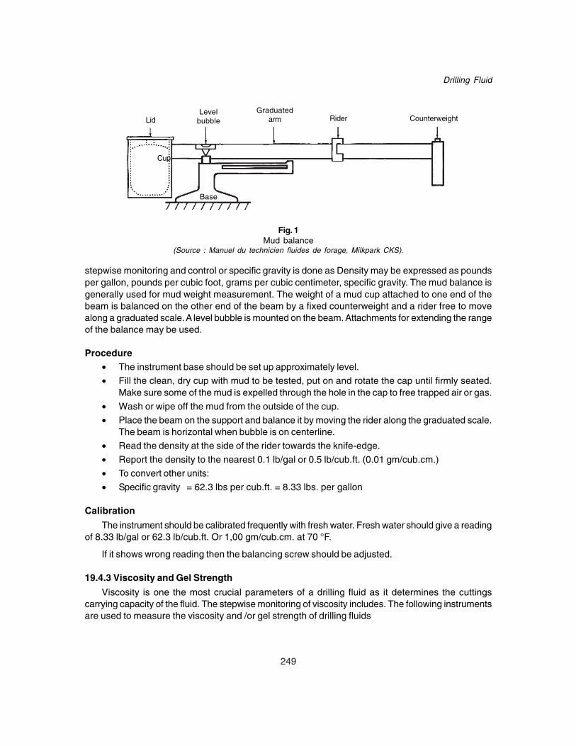
249
Drilling Fluid
stepwise monitoring and control or specific gravity is done as Density may be expressed as poundsper gallon, pounds per cubic foot, grams per cubic centimeter, specific gravity. The mud balance isgenerally used for mud weight measurement. The weight of a mud cup attached to one end of thebeam is balanced on the other end of the beam by a fixed counterweight and a rider free to movealong a graduated scale. A level bubble is mounted on the beam. Attachments for extending the rangeof the balance may be used.
Procedure• The instrument base should be set up approximately level.
• Fill the clean, dry cup with mud to be tested, put on and rotate the cap until firmly seated.Make sure some of the mud is expelled through the hole in the cap to free trapped air or gas.
• Wash or wipe off the mud from the outside of the cup.
• Place the beam on the support and balance it by moving the rider along the graduated scale.The beam is horizontal when bubble is on centerline.
• Read the density at the side of the rider towards the knife-edge.
• Report the density to the nearest 0.1 lb/gal or 0.5 lb/cub.ft. (0.01 gm/cub.cm.)
• To convert other units:
• Specific gravity = 62.3 lbs per cub.ft. = 8.33 lbs. per gallon
Calibration
The instrument should be calibrated frequently with fresh water. Fresh water should give a readingof 8.33 lb/gal or 62.3 lb/cub.ft. Or 1,00 gm/cub.cm. at 70 °F.
If it shows wrong reading then the balancing screw should be adjusted.
19.4.3 Viscosity and Gel Strength
Viscosity is one the most crucial parameters of a drilling fluid as it determines the cuttingscarrying capacity of the fluid. The stepwise monitoring of viscosity includes. The following instrumentsare used to measure the viscosity and /or gel strength of drilling fluids
LidLevel
bubbleGraduated
arm Rider Counterweight
Cup
Base
Fig. 1Mud balance
(Source : Manuel du technicien fluides de forage, Milkpark CKS).

250
Drilling Operation Practices Manual
A. Marsh Funnel
B. Direct Indicating Viscometer
A. Marsh Funnel
The marsh funnel is dimensioned so that, by following standard procedures, the out flow time ofone quart (946 cub.cm) of fresh water at a temperature of 70 + 5 °F is 26 + 0.5 seconds. Agraduated cup is used as a receiver.
Procedure1. Cover the orifice with a finger and pour a freshly taken mud sampling through the screen into
the clean, dry, upright funnel until the liquid level reaches the bottom of the screen.2. Quickly remove the finger and measure the time required for the mud to fill the receiving
vessel to the one (quart/946 cub. cm.) mark.3. Report the result to the nearest second as Marsh Funnel viscosity.
50.8 mm Inside diameter 4.75 mm
946 cm2
1500 cm220 mesh sieve
∅ 152mm
Fig. 2Marsh viscosity meter
B. Direct Indicating Viscometer
Determination of marsh formal viscosity is not enough for proper monitoring and control of drillingfluid viscosity behavior. A six speed Fan make viscometer is used to measure different componentsof viscosity and this analysis is known as Rheological Analysis.

251
Drilling Fluid
19.4.3.1 Apparent ViscosityThe apparent viscosity in centipoises equals the 600 rpm reading divided by 2
[A.V. = ø 600/2 in centipoises]
Friction force between two particles is known as Plastic viscosity.Plastic viscosity = Reading at 600 rpm - Reading at 300 rpm.
[P.V. = ø600. - ø 300 in centipoises]
19.4.3.2 Yield Point300 rpm reading - plastic viscosity[Y.P. = ø 300 - PV in lb/100 sq-ft.]
19.4.3.3 Plastic Viscosity (PV)
DIAL
ROTOR
SPRING
DIAL
ROTORBOB
Fig. 3Direct - indicating viscometer
Fig. 4Diagram of a direct - indicat-ing viscometer. Read the de-flection of the bob in degreesfrom a scale on the dial.
19.4.3.4 Fan Viscometer
Procedurei. Place a sample of drilling fluid in a suitable container and immerse the rotor sleeve exactly to
the scribed line. Measurement should be made with minimum delay (within five minutes, if
252
Drilling Operation Practices Manual
possible) and at a temperature as near as practical to that of the mud at the place of sampling(not to differ more than 10 0F or 6 0C). The place of sampling should be stated if required whenreporting the values, observed for making a zero error.
ii. With the sleeve rotating at 600 rpm, wait for the dial reading to reach a steady value (the timerequired is dependent on the mud characteristics). Record the dial for 600 rpm.
iii. Shift to 300 rpm and wait for the dial reading to come to a steady value. Record the dialreading for 300 rpm.
19.4.4 Gel Strength
Thixotropy can be estimated by observing the change in strength taking place in a gel as functionof time.
Two values, the 10 second gel strength is known as gel0 and the 10 minute gel strength is knownas gel10.
These two values, can be determined as follows:
Allow the mud to stand undisturbed for 10 seconds. Then slowly and steadily rotate at 3 rpm.Allow the mud to stand static for 10 minutes. Then again slowly rotate at 3 rpm. By this calculate gel0and gel10 in lb/100 sq-ft from dial readings after 10 seconds and after 10 minutes respectively.
• Avoid using mud samples which have high foam entrapment, as they shall give false and veryhigh readings of viscosity.
• If there is an undesirable increase in viscosity. Analyze the fluid rheology in the drill site labusing multi speed viscometer.
• If increase in viscosity of the drilling fluid is due to increase in yield point and gelatin of thedrilling fluid add deflocculated like chrome Lignosulphonate to keep the viscosity under controland desirable limits.
• If increase in viscosity of the drilling fluid is due to increase in plastic viscosity i.e. amount ofundesirable low gravity solids then add bentonite gel for dilution and run solids control equipmentmore efficiently.
• If the viscosity has gone down below acceptable levels due to inadvertent addition of undesirablequantities of water etc. enhance the viscosity by adding high viscosity reserve mud bentonitegel preferably over one cycle time of the drilling fluid.
• If there is an abrupt enhancement of viscosity due to gas influx, use degasser to keep theviscosity rise in check.
• If there is an abrupt enhancement of viscosity due to contaminants like calcium ions fromcement drilling, add soda ash to remove contaminating calcium ions and viscosity returns tonormal.
19.4.5 Filtration (Water Loss)
The filtration properties of a drilling fluid determine the amount and type of cake it shall form onthe face of any permeable formation. The monitoring and control of this property is an important as allother properties discussed before. The step wise discussion of its monitoring and control is givenbelow.

253
Drilling Fluid
Equipment
The filtration or wall building property, of a mud is determined by means of a filter press. The testsconsists of determining the rate at which the fluid is forced from a filter press containing the mudsample, under specified conditions of time, temperature and pressure, and measuring the thicknessof the residual solids film deposited on the filter paper by the loss of fluid. The API filter loss isrecorded as the number of cc’s lost in 30 minutes. API high temperature high pressure tests areconducted at 300 deg. F and at 500 psi and recorded as the number of cc lost in 30 minutes.
Wheel
Airinlet
Lid
Cell
Measuring cylinder
GasketFilter Paper
SieveGasket
Base
Fig. 5Filter Press for measuring filtrate
(Source : Milpark CKS).
Description
Essentially, the filter press consists of a cylindrical mud cell having an inside diameter of 3 inch(76.2mm) and a height of at least 2 1/2 inch (64 mm). This chamber is made of materials resistant tostrongly alkaline solutions, and is so fitted that a pressure medium can be conveniently admittedinto, and bled from the top. Arrangement is also such that a sheet of 9 cm, filter paper can be placedin the bottom of the chamber just above a suitable support. The filtration area is 7.1 + 0.1 sq. inch(45.8 + 0.6 esq.). Below the support is drain tube for discharging the filtrate into a graduated cylinder.Sealing is accomplished with gaskets. The entire assembly is supported by a stand. Pressure canbe applied with any non hazardous fluids medium, either gas or liquid. Presses are equipped withpressure regulators and can be obtained with portable pressure cylinders.
Procedure
i. Be sure each part of the cell, particularly the screen is clean and dry, and that the gasketsare not distorted or worn. Pour the sample of mud into the cell and complete the assembly.

254
Drilling Operation Practices Manual
ii. Place a dry graduated cylinder under the drain tube to receive the filtrate, close the reliefvalue and adjust the regulators so that a pressure of 100 psi (7.03 + 0.356 Kg/sq cm.) isapplied in 30 seconds or less. The test period (or duration of time) begins at, the time ofpressure application. At the end of 30 minutes, measure the volume of filtrate. Shut off theflow through the pressure regulators and open the relief valve carefully. It may be desirable touse a one-hour filtration tests for oil muds: the time interval shall be reported.
iii. Report the volume of filtrate in cubic centimeters (to 0.1 cub.cm.) as the API filtrate. Reportat the start of the test mud temperature.
iv. Remove the cell from the frame, first making certain that all pressure has been relieved.Disassemble the cell, discard the mud, and use extreme care to save the filter paper with aminimum of disturbance to the cake. Wash the filter cake on the paper with gentle stream ofwater and measure the thickness of the cake. In case of oil muds diesel may be used inplace of water for washing the cake.
Report the thickness of the filter cake to the nearest value.
• Check and ensure that its value falls within the desirable value of API fluid loss in G.T.O.
• Also record and report whether the filtrate is clear liquid or muddy fluid.
• If it is muddy fluid report that whether there was a sudden fluid loss as soon as the pressurewas applied (Which is called spurt loss).
• Measure & report the API fluid loss every six hours during normal drilling operations.
• In case the value of API fluid loss increases beyond the acceptable limits as per G.T.O. addfluid loss control additive like CMC, or PAC or PGS depending upon the type of water basemud employed.
• Measure the reduction in fluid loss of drilling fluids at least one cycle after addition of Fluidloss control additive to get the true state of the API fluid loss value.
• Ensure maintenance doses of fluid loss additive in the drilling fluid system commensuratewith amount of fluid dilution with water or bentonite gel and thermal degradation etc of theadditive at higher temperature. This shall ensure a more or less stable API fluid loss valuewithin the G.T.O. range.
• Keep the API filter press clean, dry, well serviced and maintained for its repeated use.
• During API fluid loss measurement keep a watch on the pressure value in the gauge, itshould remain at 100 psi throughout.
19.4.6 Sand ContentSand is a type of undesirable low gravity solids that gets incorporated into the drilling fluid system
from the sand stone formation being drilled. It is highly damaging to the equipments like mud pumpsetc. due to its abrasive nature and hence it is always kept at the minimum possible levels by runningdesander and desiltters regularly specially when sand stone formations are being drilled.
EquipmentSand content of mud is estimated by the use of a sand screen set. The set consists of a 200
mesh sieve 2 1/2 inch (63.5 mm) in diameter, a funnel to fit to screen and glass measuring tube. Themeasuring tube is marked for the volume of mud to be added in order to read directly the percentageof sand in the bottom of the tube, which is graduated from 0 to 20 percent.

255
Drilling Fluid
Procedurei. Fill the glass measuring tube to the indicated mark with mud. Add water to next mark, close
the mouth of the tube and shake vigorously.
ii. Pour the mixture, into the clean, wet screen, Discard the liquid passing through the screen.And more water to the tube, shake and again pour onto the screen. Repeat until the washwater passes through clear. Wash the sand retained on the screen to free it of any remainingmud.
iii. Fit the funnel upside down over the top of the screen. Slowly invert the assembly and insertthe tip of the funnel into the mouth of the glass tube. Wash the sand into the tube by playingof fine spray of water through the screen. Allow the sand to settle. From the graduations onthe tube read the volume percent of the sands.
iv. Report the sand content of the mud in volume percent. Report the source of the mud sample,i.e. above shaker suction pit etc. Coarse solids other than sand will be retained on the screen.
19.4.7 Liquids and Solids
EquipmentA retort is used to determine the quantity of liquids and solids in the drilling fluid. Mud is placed
in a steel container and heated until the liquid components have been vaporized. The vapors arepassed through a condenser and collected in a graduated cylinder and the volume of liquid is measured.Solids, both suspended and dissolved are determined by difference.
Procedurei. Procedure will vary slightly, depending upon the apparatus used. Keep the interior of the mud
chamber smooth by cleaning after every use.ii. Place a measured volume of deaerated mud in the chamber. Insert fine steel wool above the
sample and add a drop of defoaming agent. Close the retort. The hole in the lid of thecontaining vessel must not be blocked. Put a clean graduated cylinder under the condenserdischarge.
iii. Heat the retort, continuing 10 minutes after no more condensate is being collected in thegraduated cylinder. The addition of a drop of wetting agent promotes separation of oil andwater droplets. Read to volume of oil and water collected.
iv. From the volumes of oil and water collected and the volume of the original mud samples, thepercentage by volume of oil, water and solids in the mud can be calculated.
• Calculate the solids content % by volume as underi. % Water by volume = ml of water x 10ii. % Oil by volume (if any) = ml. of oil x 10iii. % Solids by volume = 100 – (ml. of water + ml. of oil) x 10iv. Gms of oil = ml. of oil x 0.8v. Gm of water = ml. of water x 1vi. Gms mud = 10 x sp.gr. of mudvii. Gms of solids = (vi) – (v + iv)viii. MT solid = 10 – (ml. oil + ml. water)ix. Average sp.gr. of solids = (vii) / (viii)

256
Drilling Operation Practices Manual
x. Solids % by weight = (vii) / (vi) x 100xi. High Gravity Solids % by volume (4.3) = (ix – 2.5) x 55.6xii. Low Gravity solids % by volume (2.5) = 100 - xi
19.4.8 pH Measurement
The conventional water based drilling fluids are dependent on specialized additives for theirperformance. The performance of these additives is in turn largely dependent on the pH value of themud. If has been observed by laboratory experimentation as well as field experience that the CL /CLS based inhibitive dispersed system perform most efficiently when pH of the drilling fluid liesbetween 9.5 and 10.5 and hence it is necessary to maintain pH of the drilling fluid always within thisrange.
• The stepwise monitoring and control of pH value of mud is done as under.• Keep a regular check on the pH of the drilling fluid used.
The pH of a drilling fluid indicates its relative acidity or alkalinity. Double-distilled water is neutral,that is, it is neither acid nor alkaline. On the pH scale, this point is indicated by the number 7. Acidsrange from just below 7 for slight acidity less than 1 for the strongest acidity. Alkaline solution rangefrom just above 7 for slight alkalinity to 14 for highest alkalinity.
Two methods for measuring the pH of drilling mud are used. These are: -i. A modified colorimetric method, using paper test strips.ii The electronic method, using the glass electrode.
The paper strip method may not be reliable if the salt concentration of the sample is high. Theelectrometric method is subjected to error in solutions containing high concentration of sodium ions,unless a special glass electrode is used, or unless suitable correction factors are applied in using theordinary electrodes. In addition, temperature correction should be made in the electrometric methodof measuring pH.
19.4.8.1 Paper Test Strips
The test paper is impregnated with dyes of such nature that the colour is dependent upon the pHof the medium in which the paper is placed. A standard colour chart is supplied in a wide range type,which permits estimation of pH to 0.5 unit, and in narrow range papers with which the pH can beestimated to 0.2 unit.
ProcedurePlace 1 inch strip of indicator paper on the surface of the mud. Allow it to remain until the liquid
has wetted the surface of the paper and the colour is stabilized. Compare the colour of the upper sideof the paper (which has not been in contact with the mud solids) with the colour standard, providedwith the test strip and estimate the mud pH.
9.4.8.2 Glass Electrode pH MeterThe glass electrodes pH meter consists of a glass electrode system, an electronic amplifier and
a meter calibrated in pH units.
The electrode system is composed of:

257
Drilling Fluid
i. The glass electrodes, which consists of a thin walled bulb made of special glass within whichis sealed a suitable electrolyte and electrode.
ii. The reference electrode, which is, saturated calomel cell. Electrical connection with the mudis established through a saturated solution of potassium chloride contained in a tubesurrounding the calomel cell. The electrical potential generated in the glass electrode systemby the hydrogen ions in the drilling mud is amplified and operates the calibrated meter, whichindicates pH.
Procedurei. Make the necessary adjustment to put the amplifier into operation and standardize the matter
with suitable buffer solution, according to directions supplied with the instrument.ii. Wash the tips of the electrodes, gently wipe dry and insert them the mud contained in a
small glass vessel. Stir the mud about the electrodes by rotating the containers.iii. Measure the mud pH according to the directions supplied with the instrument. After the
meter reading becomes constant, which may require from 30 seconds to several minutes,record the pH.
19.4.9 Methylene Blue Test for Cation Exchange Capacity
This test is carried out to know the amount of active clay content of the drilling fluid. This gives ananalysis of low gravity solids in the sense that what amount of these solids are active and how muchis inert solids. This helps in planning the treatment for control of rheology by control on solids typeand behavior.
The following materials are required to estimate the cation exchange capacity of drilling mudsolids or clays.
i. Methylene blue solution(3.74 gm U.S.P. grade methylene blue per 1000 cub.cm.)1 cm = 0.01 mille equivalent.
ii. Hydrogen peroxide - 3% solution.iii. Dilute sulfuric acid (Approx. 5N)iv. One 2.5 cub.cm. or 3 cub.cm. syringev. Flask, Burette, graduated cylinder, Hot plate, filter paper etc.
Procedure
i. Add 1 cc of mud to 10 cc of water in a 250 cc flask. Add 15 cc of 3% hydrogen peroxide and0.5 cc of dilute sulfuric acid (about 5N) and boil gently for 10 minutes. Dilute to about 50 ccwith water.
ii. Add Methylene blue solution to the flask from a pipette or burette, after each 0.5 cc ofmethylene blue is titrated into the flask, shake the contents of the flask for about 30 seconds.While the solids are still suspended, remove one-drop liquid with a stirring rod and place it onfilter paper.
When dye appears as a greenish-blue ring surrounding the dyed solids detected.
iii. Shake the flask an additional two minutes and place another drop on the filter paper. If theblue ring is again evident, the end point has been reached. If the ring does not appear,continue as before until a drop taken after shaking 2 minutes shows a blue tint.

258
Drilling Operation Practices Manual
iv. Mud as methylene blue capacity, calculated as follows.
cc of methylene blueCapacity = ————————————
cc of mud
In addition to bentonite that absorb methylene blue. Treatment with hydrogen peroxide is intendedto remove the effect of organic materials such as CMC. Polyacrylates, lignosulfonates and lignite. Ifother absorptive material is not present in significant amounts, the bentonite content of the mud canbe estimated as follows.
Bentonite in mud (ppb ) = 5 x methylene blue capacity
19.4.10 Filtrate AnalysisSuch chemical tests are made on mud filtrates to determine the presence of contaminants, such
as salt or anhydrite, or to assist in the control of mud properties. For example, the test for alkalinityin high pH muds. The same tests can be applied to make up waters, which in some areas containdissolved salts, which affect mud treatment.
19.4.11 Alkalinity DeterminationsBecause the pH scale is logarithmic, the alkalinity of a high pH mud can vary up to a considerable
amount with no measurable change in pH. In highly alkaline system; analysis of the mud filtrate todetermine the alkalinity yield more significant results than pH measurement.
Procedure for The Alkalinity Test
Measure one or more cubic centimeter of fresh filtrate into a 125 ml flask.i) Add 2 to 3 drops of phenolphthalein indicator solution.ii) Add 0.02 normal (N/50) sulfuric acid from an automatic burette or a pipette, stirring continuously,
until the sample turns from pink to colour less, if the sample is so coloured with chemicalsthat this end point is masked, the end point is then taken when the pH drops to 8.3 using theglass electrodes pH meter. The number of cub.cms. of 0.02 normal (N/50) sulfuric aciddivided by the cub.cms. of sample taken is called the “P” alkalinity of the filtrate (Pf).
iii) To the sample, which has been titrated to the “P” end point, add 2 to 3 drops of methyl orangeindicator solution. Add standard acid drop by drop from the pipette while stirring until thecolour of the solution changes from orange to pink. Record as “Mf” to total volume of acid inthe cub.cms. used to reach the methyl orange end point, including that of the “P” end point.If the sample is so coloured that the change in colour is not evident, the end point is takenwhen the pH drops to 4.3 as measured with the glass electrode pH meter.
iv) Report the methyl orange alkalinity of the filtrate, ml, as the total cub.cms. of 0.02 normalacid per cubic cm of filtrate required to reach methyl orange end point.
19.4.12 Lime Content EstimationSome knowledge of the amount of excess lime present is of considerable value as an aid in
controlling the properties of a lime treated mud. An estimation of lime content can be made based onalkalinity titration of the filtrate and of the whole mud. The titration of the mud must be made rapidlyto permit titration of calcium hydroxide and sodium hydroxide without interference from calciumcarbonate.

259
Drilling Fluid
The procedure for estimating the lime content is:
i. Measure one cc of mud into a conical flask and dilute to about 50 cc with distilled water. Aveterinary syringe is satisfactory for measuring even very thick mud. While a pipette may beused for thinner muds.
ii. Add 4 to 5 drops of phenolphthalein indicator solution. A pink colour develops.
iii. Add 0.02 normal (N/50) sulfuric acid rapidly from a burette or pipette, stirring continuously,until the colour changes from pink to the colour of the mud. The number of cub.cms. of 0.02acid divided by cub. cm. of sample taken is called the “P” alkalinity of the mud (Pm).
iv. Determine the “P” alkalinity of the filtrate (Pf).
v. Determine the lime content as follows: -
vi. 0.26 (Pm - Pf) = equivalent calcium hydroxide (lb/bbl)
vii. where,
viii. Pm = cc 0.02 N acid for P of mud
ix. Pf = cc 0.02 N acid for P of filtrate
19.4.13 Salinity Analysis / Salt Concentration [Chloride] TestThe salt or chloride test is carry significant in areas where salt can contaminate the drilling fluid.
Salt water flows, can contaminate the drilling fluid in the hole. Salt tests are among the means ofdetecting these flows when the chloride content exceeds 600 PPM, it may be necessary to alter themud program.
The test is made on a portion of the original filtrate, or on the sample from the alkalinity test towhich a pinch of calcium carbonate has been added. The chloride content test procedure follows.
i. Measure a sample of any convenient volume, from one cc to 10 cc, into the conical flask anddilute to about 50 cc with distilled water.
ii. Add a few drops of phenolphthalein indicator. If a pink colour develops add sulphuric acid untilit completely disappears. If phosphates have been added in large quantities, add 10 to 15drops of calcium acetate solution.
iii. Add four or five drops of potassium chromate indicator to give the sample a bright yellowcolour.
iv. Add standard silver nitrate solution a drop at a time stirring continuously. The end point of thetitration is reached when the sample first changes to orange or brick red.
Calculate the chloride (Cl) content as follows.
CC of silver nitrate x 1,000Cl content in mg per liter or PPM = ——————————————————
CC of sample in the standard solution
If 1.0 cc = 1 mg Cl, or 4.7910 gm of AgNO3 per liter (0.0282N)
CC of silver nitrate x 10,000or = ——————————————————
CC of sample in the standard solution
If 1.0 cc = 10 mg Cl, or 47.910 gm of AgNO3, per liter (0.282N)

260
Drilling Operation Practices Manual
19.5 DRILLING FLUID ANALYSIS AT DRILL SITE AND ITS SIGNIFICANCE
The on site drilling fluid analysis carried out in the well site drilling fluid laboratory provides veryuseful and valuable information regarding drilling fluids behavior and characteristics. This analysis isessential and very important as it provides the following types of information.
• It helps in diagnosis of potential drilling fluid problems and probable down hole complicationbefore the problem gets aggravated.
• It serves as a crucial tool in diagnosis of drilling fluid maintenance problems and hencetrouble shooting becomes easy, fast and focused.
• It helps in monitoring the general health of the drilling fluid and also the effect of treatment onvarious properties.
• It also helps in monitoring the efficacy of different drilling fluid additives in terms of a qualityand optimum dose, which helps in optimizing the treatment of right type of additive in rightamount.
• It also helps in monitoring the optimum performance levels of solids control equipment, anda suitable corrective action may be taken well in time if the performance falls below expectedlevels.
19.6 TROUBLE SHOOTING OF DRILLING FLUID RELATED PROBLEMS
The foregoing description of methods of drilling fluid maintenance and drilling fluid analysis at drillsite with its significance are the key guiding principles of maintaining drilling fluid parameters withindesirable limit or as per G.T.O. as the case may be. More often than not, however, the drilling fluidengineer on site encounters situations when these vital drilling fluid parameters go beyond windowsof acceptable range. In such case an early action is recommended which involves diagnosis of thecause of trouble and then trouble shooting the same by most appropriate and cost effective remedialaction. The details of various recommended trouble shooting procedure are given below based on thetypes of trouble encountered.
19.6.1 Rise in Specific Gravity• Every section of the hole is drilled with a certain desirable specific gravity range based on the
pore pressure and fracture pressure values of the formation exposed in that section of thehole. Besides control of pressured and highly dipping formations also some times requirehigher values of specific gravity of drilling fluid. If however the specific gravity of drilling fluidrises above the desired values the main cause is accumulation or build up low gravity solidswhich must be curtailed and thrown out to keep the specific gravity of the drilling fluid incheck. Following step wise procedure is recommended for trouble shooting this event.
• Check the type of formation being drilled, if it is sand, silt, or compact shales than thespecific gravity build up is due to inefficient application of solids control equipment.
• Check the shale shaker for efficiency and screen size ensure proper size screens are installed.Preferably 60 or 80mesh at the bottom if the prevalent flow rates permit the same.
• Make sure that integrity of screens is intact & they are not torn. If torn replace them immediately.• Do not bypass shale shakers to avoid mud wastage through them in case of high flow rates
instead enhance their efficiency by their proper servicing and maintenance.• Always ensure thorough and regular cleaning of shaker screens for its optimum efficiency.• Check the desander cones for their efficiency. This can be done by checking the desirable
pressure developed on the head of hydro cyclones. If there is leakage get it rectified immediately.
261
Drilling Fluid
• Ensure that cones are in good condition and they are not mud cut.• Ensure that the nozzle size of desander is proper. This can be checked by inserting finger
through the nozzle while desander is running. If a distinct force is experienced by the fingertending to suck it in, the nozzle size of the desander is correct. This force is developed dueto central portion created in an efficient vortex of a hydro cyclone.
• Watch the discharge of cones, it must be a spray discharge. If any time rope discharge isobserved get the cone checked and corrected immediately. Rope discharge means inefficientoperation of hydro cyclone (desander & desilter).
• During round trip, clean and service the cones of desander & desilters for their efficientoperation in next cycle.
• Measure the specific gravity of under flow (i.e. discharge of cones. This shall give an idea ofefficient running of desander.
• Follow all above guidelines for proper operation. Maintenance, and servicing of the desilter also.• Run both desander and desilter simultaneously to remove the undesirable low gravity solids
upto silt range. This shall certainly reduce the specific gravity of drilling fluid and it may comewithin the desirable range.
• Once the specific gravity has come within desirable range maintain it at that level by prudentalternate operation of desander or desilter and efficient use of shale shaker.
• Use Linear Motion shale shaker and Linear Motion Mud cleaner if available, for most efficientsolids control results.
• In case the formation being drilled is soft clay, the rise in specific gravity is due to particlesfiner than silt range and a good number of them may fall in colloidal size range. The onlyoption for their control and weight reduction is by dilution with base liquid i.e. water or brineas the case may be hence dilute with water at an optimal rate commensurate with rate ofdrilling (ROP) to nullify the effect of clay solids getting mixed in the system.
• For every cubic meter of water being added. Add desired quantities of caustic soda formaintaining pH, fluid loss control additive, and other speciality additives composed in theprevalent mud so that their percentage dosages are maintained.
• Once the specific gravity reaches desirable value minimize water or base fluid addition alongwith other chemicals and additives, to a level to maintain specific gravity at that desired level.
19.6.2 Fall in Specific GravityThe fall in specific gravity in case of weighted drilling fluids is a rare phenomenon. However, if it
occurs, an immediate remedial action must be initiated before the control on the formation is lost andthe well becomes active. The following steps are recommended to trouble shoot this problem.
• Check if there was an inadvertent mixing of water or low gravity fluid in the active circulatorysystem of drilling fluid. It may be due to a leaking tap or valve failure allowing transfer of wateror low gravity fluid like reserve bentonite gel in the active system. If such is the case rectifythe cause of dilution of drilling fluid immediately.
• Measure the present specific gravity of the drilling fluid and add calculated amount of weightingmaterial i.e. barites over one or two cycles, homogenously till the fluid specific gravity reachesback again to the desired value.
• In case the fall in specific gravity is due to undesirably low viscosity of the drilling fluid, whichis unable to suspend barites in the system, then build up viscosity immediately by adding

262
Drilling Operation Practices Manual
highly viscous bentonite suspension till it is able to suspend barites again for desired specificgravity.
• Add more barites to compensate for the added low specific gravity, high viscosity gel.• Maintain the desired specific gravity of mud by ensuring the minimum required viscosity to
suspend the weight material.
19.6.3 Rise in ViscosityThis is one of the most common problem encountered during operations and needs proper diagnosis
after careful analysis of the causes of the problem. The causes of high viscosity or unacceptable risein viscosity may be due to one or more of the following reasons.
• Drilling through bentonitic/ Montmorillonite mud making shales for example gumbo shales inwestern offshore, Mehsana etc.
• Contamination of drilling fluid with monovalent or divalent cation eg: Ca++ contamination whiledrilling through cement and Na+ / Ca++ / Mg++ contamination while salt-water flow areencountered through pressured formations.
• Effect of high temperature in excess of 1200C, specially if drilling fluid is subjected to thisbottom hole temperature under static condition over prolonged periods eg: while tripping longhole sections shut down due to surface or subsurface complication etc
• Accumulation of excessive amount of low gravity solids though un-reactive is due to inefficientoperation of solids control equipment.
Depending upon the cause of rise in viscosity following steps is recommended to troubleshoot this problem.
• Analyse the drilling fluid in well site laboratory using a multi speed viscometer.• Calculate plastic viscosity, yield point and 10 second and 10 minute gel strength of the fluid.• Compare these results with the results of the fluid just before the rise in viscosity occurred.• In case there is a substantial increase in yield point and gel values and that too more in 10
minute gel values of drilling fluid and the formation being drilled are Montmorillonite rich mudmaking shales, dilute the drilling fluid sufficiently to keep the colloidal clay content within limits.
• Add deflocculant along with caustic soda in sufficient quantities to get the drilled clays all indeflocculated condition.
• Add other ingredients of drilling fluid like Chrome Lignite, drilling detergent, caustic soda,fluid loss control additive etc. to make up for the dilution rate so that their optimum percentagedoses are always maintained in the drilling fluid.
• Continue the above treatment till the viscosity comes back to desired level or range.• Maintain the viscosity of this level by frequent and regular treatments of above chemicals so
long as the problematic shale section is under drilling fluids is cased.• In case there is rise in viscosity associated with rise in yield point and gels but the formation
being drilled are relatively inert to the drilling fluid partial thermal degradation of deflocculantalong with reaction of clay with caustic soda at this temperature (> 1200C / 1500C or more)may be the cause of this unacceptable rise in viscosity.
• Add replenishment dosages of deflocculant after every 2-3 cycles so that they never fallbelow minimum required levels.
• Add sufficient quantity of fresh gels (of lower viscosity) and caustic soda to replenish thereacted components.
263
Drilling Fluid
• Always keep pH in the range of 9.5 to 10.5.• Maintain the above treatment plan to ensure viscosity in the desirable range.• Add resinated lignite for high temperature fluid loss control and Sulphonated Asphalt for
better bore hole stabilization.• This combination not only provides a good gauge borehole better mud lubricity but also
contributes significantly to the high temperature rheology stabilization of clay based inhibitivedispersed drilling fluids.
• In case the cement is being drilled or there is a significant salt water flow contaminating thefresh water drilling fluid the resultant rise in viscosity shall invariably be associated with highvalues of yield point and gels.
• The drilling fluid in such cases is in flocculated state. If it is cement drilling Add soda ash totreat out cement.
• Add deflocculant like CLS to bring the drilling fluid back to in its original deflocculated state.• Since cement provides for alkalinity maintain pH between 9.5 and 10.5 while adding
deflocculant. The pH value should not be allowed to fall below 9.5• If it is due to contamination by salt water flows etc isolate the patch of mud which is highly
flocculated in a separate tank.• Add barytes to drilling fluid to raise its specific gravity so as to stop the salt water flow from
the formation.• Treat the mud with deflocculant and caustic soda to bring the viscosity back to the normal
range.• Add other chemicals also like fluid loss control agent, chrome lignite, Shale stabilizer etc.
So as to maintain their dosages after dilution with formation water flows.• Maintain specific gravity of the mud above the formation pressures to keep any further influx
of undesirable formation fluids.
19.6.4 Fall in Viscosity
Although the unacceptable fall in viscosity is phenomenon of lesser occurrence, it is equallyimportant. If it is not rectified promptly it may lead to settling of cuttings and barytes in the well borecausing stuck up due to cuttings pack off and mud loss due to resultant pressure buildup below thepacked up well bore. The main cause of this is dilution of mud accidentally or gradually to a level thatpercentages of viscosifier go down below minimum required limits.The steps wise recommendationsto trouble shoot this problem is as under:
• Add viscosity building thick bentonite gel to the active circulating drilling fluid system insufficient quantities preferably over a cycle.
• Continue above addition till the viscosity rises again to the desired range.• Prepare a viscous pill of bentonite with some lime and CMC and circulate it through the
bottom of the hole. This shall unload the well of any settled cuttings etc and clear the boreholeof such undesirable loading of solids.
• Maintain addition of high viscosity bentonite gels while drilling through patches of inertformations like clean sand stones or other hard rock areas.
19.6.5 Fluid Loss and ControlIn relatively deeper sections of the hole, a prudent fluid loss control regime is necessary to avoid
uncontrolled flow of drilling fluid’s liquid phase to formation pores and channels. This requirement

264
Drilling Operation Practices Manual
becomes even more important when permeable sand stone sections are drilled. If fluid loss values ofthe drilling fluid goes above the desired limits and permeable formations are exposed, the risk of adifferential stuck up gets greatly enhanced due to formation of a thick fluffy bentonite cake against theformation face of the well bore. It is therefore, essential to keep the fluid loss value within desirablelimits and for that following steps are recommended.
• If the fluid loss values has gone above desirable limit check the type of cake deposited on thefilter paper. Also check if there was a spurt loss when the fluid loss was measured using APIfilter press. Normally both spurt loss and a fluffy cake shall be observed.
• Check the mud rheological parameter, if the viscosity yield point and gels are within thedesired limit, add fluid loss control additive over a cycle so as gets its homogenized mixingwith the fluid.
• Let the mud be conditioned for one more cycle after addition of fluid loss additive.• After that measure API fluid loss again and observe and record the drop in fluid loss value,
spurt loss if any and quality of mud cake.• If the new fluid loss value falls within desirable range and there is no spurt loss and cake has
become thin & tough in appearance, the desired percentage of Fluid loss additive is achievedin the system.
• Maintain this desired dosage by regular intermittent treatment of the fluid loss additive dependingupon the rate of drilling and rate of dilution of drilling fluid with water and / or bentonitic gel.
• If the new fluid loss value does not fall within desirable range continue addition of fluid lossadditive as per above procedure till the desired value of API fluid loss is achieved.
• If the rise in fluid loss value of the drilling fluid is associated with concurrent rise in viscosity,yield point and gels, the drilling fluid is flocculated. Add sufficient quantity of deflocculant eg;CLS and caustic soda till viscosity / Rheology parameter fall within desirable limits
• Measure API fluid loss again of the deflocculated drilling fluid system. It is likely to havedesired values of fluid loss, otherwise small quantities of fluid loss agents may be required tobring the fluid loss to desirable levels.
19.7 SPECIAL OPERATIONS RELATED TO DRILLING FLUIDSThe most important and vital of uncertainties related to drilling fluid are down hole complications
encountered during drilling important and specially modified / treated drilling fluid or other fluids areemployed to successfully tide over these problems or complications. The down hole complication vis-à-vis the role of drilling fluid engineer in handling them are given below.
19.7.1 Loss Circulation-Detection and ControlLoss of circulation or mud loss is one of the most common down hole complication encountered
during drilling. This is a condition in which drilling fluid or mud is lost to subsurface formations eitherpartially or completely. In case of partial losses there are partial returns and in case of completelosses there are no returns.
The loss of circulation may result due to highly permeable and unconsolidated formations atshallow depths and in such case the losses are partial and these are known as seepage losses.
The loss of circulation at deeper depths occurs in fractures, these fractures may be natural orinduced. The losses here may be partial to total depending upon severity of fractures. Even if thelosses are partial initially and suitable measures are not taken in time, their amount increases and

265
Drilling Fluid
they become total or near total to widening of already existing fractures. Total losses are also commonin lime stone formations (eg. Mumbai High L-III Reservoir) due to presence of vugs and cavern. Thefirst and foremost step recommended for loss of circulation is its early detection. The following isrecommended.
• Always monitor volumes of active pit closely and regularly any volume additions and transfersmust be in variably recorded.
• Always monitor return from the well at the shale shaker.• Ensure there are no leakage or surfaces losses of the drilling fluid.• Any significant reduction in active pit volume along with reduction in return flow is an indicative
of loss of circulation.• Severe partial loss or total loss is easily detected as there is a fast reduction in active pit
volume and almost no return on the shale shaker.• The moment loss of circulation is observed, stop drilling ahead and circulate drilling fluid at
lower pump rates. Monitor active pit volumes for calculating the rate of loss.• Analyze & identify the probable zone of loss, in competent formations it is usually just below
the casing seat of the previous casing.• Mix a pill of bridging materials like Mica flakes, Walnut shells, Rice husk, Sawdust, Baggage,
etc in the separate tank.• Always try to mix pill with a blend of bridging materials like, flaky Mica flakes and granular
walnut shell be use do to mix an effective LCM pill.• Mix sufficient quantity of bridging material to make the pill. An effective pill should have 30 lbs
/ bbl of the material mixed in drilling fluid being used.• Use equal portions of different components for blending the bridging material mixture.• Pump and place the pill slowly against the zone of loss.• Meanwhile, if the loss is below the casing shoe, pull out the string upto the casing shoe and
stop circulation of drilling fluid while LCM pill is being prepared in the pits.• Circulate drilling fluid to cut down specific gravity of the fluid by dilution with bentonite gel.• Ensure that hole is always kept full of drilling fluid to avoid well bore instability and influx of
fluids from the pressurized formations.• Once the pill is placed against the zone of loss allow time for healing of the fracture by
bridging materials of the pill.• If the loss is contained under static condition after application of LCM pill, restart circulation
of the fluid at reduced pump strokes and observe for any loss of circulation under theseconditions.
• If there is no loss now, stop circulation and run in the string slowly to the bottom.• Restart circulation at reduced pump rates and circulate for one or two cycles to ensure that
problem of loss circulation has bee tackled successfully.• If the well bore and formation pressures permit further reduce specific gravity by bentonitic
gel dilution to the lowest permissible safe limits.• Resume drilling to next casing depth and case the section to avoid any recurrence of losses.• After a loss ensure that all tripping operations, and running in of casing pipe etc must be
handled very slowly and smoothly. No pressures surges are allowed, as that shall aggravatethe problem.

266
Drilling Operation Practices Manual
• In case bridging materials fail to seal the zone of lost circulation try other materials likeDiesel M plugs. Diesel oil bentonite plugs (DOB plugs) or diesel oil bentonite cement plugs(DOBC plugs)
• If the above also fail pump appropriate quantity of cement slurry to seal the zone of loss.• Losses to buggy or cavernous lime stone formations are not controlled by any of the above
formulations. For such losses try thermosetting cross linked Gauss Gum based formulations(Thermo gel). Their gels are acid soluble and hence may also be applied for controllinglosses in pay zones or reservoirs.
• In case losses are severe and total in huge caverns in lime stone formations down hole, drillblind with water and set casing as soon as the loss zone is drilled through.
• Use drillable plugs for controlling such losses, if available. These plugs are set inside theborehole including the loss zone. The plugs then can be drilled through and they provideprotection against losses to such severe loss zones.
• Never use bridging materials, cement etc for controlling losses in reservoir or pay zones asthey shall permanently damage the reservoir formation.
• Always ensure that bridging material particle size is smaller than bit nozzle otherwise it shallchoke them. In case larger particle size bridging materials is to be used, pull out of hole andrun-in with open end drill pile to pump such material.
• Follow good drilling practices to avoid pressure surges in the well bore.
19.7.2 Stuck Up- Detection and ControlStuck up is also one of the most common down hole problems leading to drilling complication.
The problem has become more frequent and important in the light of greater number of directionalwells being drilled in quest for more oil and greater recovery. Since the drill string has an unequal loaddistribution i.e. heavier BHA and no hole is truly vertical (i.e.00) a good portion of the string bearsagainst the side of the well bore. This becomes more complicated and amplified in case of directionalwells.
With such a situation prevalent down hole, if string becomes motion less even for small periodsof time and there is sufficient pressure differential i.e. Ä P = Pm – Pf (where Pm = pressure of the mudcolumn and Pf = formation pressure), there is a very high risk of drill string getting stuck up in the filtercake of the borehole wall. Such a condition is called differential sticking.
Differential sticking is only a type of stuck up. Besides the string may also get stuck due to acrooked hole. In this case a portion of the string goes inside the bore hole wall where the hole iscrooked (popularly called a dog leg). The string forms a seat for itself there and hence this type ofstuck up is called a ‘Key-Seat’.
The third type of stuck up may occur due to packing off of annulus with cuttings. If the mudrheology is not proper or the rate of cleaning / cleaning efficiency of drilling fluid is much lower thanrequired for whatever, reasons, the cuttings / cavings accumulate in the annulus and pack off theannular space between the string and the bore hole so tightly that it gets stuck.
Whatever may be the type of stuck up, it is necessary to act immediately to liquidate the problembecause with time the stuck up may become more complicated and severe which sometimes maycause costly fishing sobs, side tracks or even well abandonment.

267
Drilling Fluid
Trouble Shooting• Identify and record the moment stuck up occurs on the well site. It is very easily to identify a
stuck pipe, which can neither be rotated nor be moved up and down.• Find out the type of stuck up for this correlate well parameters, with immediate well history,
BHA configuration, type of formation, presence of open hole dog legs, drilling fluid rheologyand hole cleaning pattern vis-à-vis rate of drilling etc.
• In case, the BHA is against a highly permeable formation being drilled, and the pipe hasremained motion less against this formation for a considerable period of time there are nosevere dog legs and mud viscosity is sufficient for effective hole cleaning then most probablyit is a differential stuck up.
• Once differential stuck up is established calculate the annular volume required to cover theentire BHA length.
• Mix a spotting fluid pill in HSD twice the above calculated annular volume to cover the BHA.• Pimp this pill of spotting fluid slowly through a cementing unit and place it in the annulus
against the BHA, so that it completely soaks the BHA of the string.• Displace only small quantities of the pill at a time.• After every displacement wait for 30-45 minutes for the pill to react with the cake etc. in which
drill string is stuck.• Intermittently work on the pipe to see if it is free.• A differentially stuck pipe shall come out free even in one proper application of spotting fluid.• If the string does not get released even after 6 hours or so of the above spotting exercise then
repeat the whole process of spotting against the stuck zone and follow the steps just asdescribed.
• The differentially stuck string shall come out free if spotting fluid quality is good and properprocedure as outlined above is followed.
• If the stuck up is due to a key seat in which case the string can be moved downwards onlybut it can neither be rotated nor it can be moved upwards, the spotting fluid shall not help infreeing the pipe, follow fishing techniques to liquidate the problem.
• If the stuck up is due to annular pack off associated with poor returns of fluid on the shakerscreen, low viscosity or very high drilling rate or excessive caving which prevents propercleaning of the annulus stop drilling ahead immediately.
• Stop circulation or circulate at such a low rate that shall not cause pressure build up andinduced fracture below the pack off zone. Otherwise loss of circulation shall also start.
• Prepare a high viscosity pill in a separate tank by using thick bentonite gel, CMC, lime andhigh viscosity grade polymers if any available on the site.
• Pump this viscous pill to sweep off the cuttings etc from the annulus.• Continue circulation at rates low enough to keep the annular pressure losses low but sufficient
to raise the mass of cuttings etc. packing off annulus to the well mouth.• Once the hole annulus is unloaded, condition the drilling fluid to have sufficient viscosity to
clean the hole efficiently.• If hole is prone to caving due to dipping formations or pressured shales, raise specific gravity
to minimize this caving so that combination of drilling fluid viscosity and flow rate can effectivelyclean the annulus.

268
Drilling Operation Practices Manual
19.7.3 Gas Influx-detection and Control
Permeable formation charged with high-pressure hydrocarbons are the objectives of all oil welldrilling operations. In the process of drilling for exploration of new areas a number of times permeableformation containing pressured fluids, mainly gaseous, are encountered. If the pressures of theseformations are not known at the planning stage the existing drilling fluid may not be able to contain orcheck these pressures and the formation pressure (Pf) at that point of time exceeds the pressureexerted by the column of drilling fluid (Pm) i.e. Pf > Pm. In such a case the formation gases, whichmay be hydrocarbons, flow into the well bore with great force and in large volumes. These gasesexpand tremendously in their journey upwards due to reduction in pressure and very large volumesmixed in drilling fluids manifest at the well mouth. This situation is known as “Gas Influx.”
If an early detection and control is not taken up, the influx increase exponentially with time due totremendous reduction of weight of the mud column in the annulus and it may cause entire annulus tobecome empty of any liquid drilling fluid whatsoever. The gas than flows in large volumes and withgreat speed to well mouth and well must be immediately shut in by closing suitable rams of blowoutpreventer. Such a situation is known as “Kick”. Once a “Kick” is encountered and well shut in, it mustbe killed by pumping in heavy mud through the string and / or Annulus.
However if Kick is not controlled immediately the uncontrolled flow of gas or oil & gas both startsfrom the drilled hole. If this flow is a mix of hydrocarbons it soon catches fire and the entire rig is burntdown. This is a major crisis situation and is known as “Blow out “. Blowouts need to be preventedbecause it causes loss of man, material and even the well. A number of times the well gets collapsedand requires abandonment.
If the downhole problem of Gas Influx is detected early and a suitable remedial action is properlyplanned and executed, it is possible to avoid complications like Kick and Blowout. The followingsteps are recommended for detection and control of Gas Influx during drilling operation.
• Maintain a close watch on viscosity and specific gravity of mud while drilling through apermeable formation like sand stone etc.
• Measure their parameters of viscosity and specific gravity of out coming mud more frequentlysay after every 15-20 minutes interval especially if gas influx is anticipated.
• A sudden rise in viscosity of the out coming drilling fluid with an enhanced flow rate at theshale shaker indicates gas influx.
• Check for flow rate in the return line with driller, an increase shall confirm gas influx.• Check if the pump rate is same or increased. Increase in pump rate reconfirms the gas influx.• Immediately start the degasser & stop drilling ahead.• Check the specific gravity of out coming mud immediately and frequently i.e. every 5 minutes.• Adjust circulation rate to avoid over flow of drilling fluid at the shales shaker to avoid wastage
of drilling fluid.• Start raising the specific gravity of ingoing active pit.• Stop circulation for a while and check for self flow.• Shut in pipe rams of Blow out preventer and record shut in pressures developed in the annulus.• Discuss and decide on killing method with the drilling Engineer and follow the exact guidelines
on kill mud weight requirement in terms of specific gravity and volume of the kill mud required.• Prepare kill mud of the desired specific gravity at the fastest possible pace in a separate mud
tank.

269
Drilling Fluid
• Once the kill mud is ready coordinate with the Drilling Engineer of the rig for its properpumping and placement in the well to kill the well.
• Once the high pressure gas influx is controlled by killing operation, resume mud circulationwith a higher specific gravity which must be more than formation pressure (i.e. Pm new > Pf)
• Continue circulation with new higher specific gravity drilling fluid for one or two cycles stopcirculation intermittently and check for self flow. There should be no self flow or gas influx.
• Resume normal drilling operation with new higher specific gravity mud.
19.7.4 Caving – Detection and ControlBorehole instability is one of the most common down hole complications encountered in oil well
drilling. Most of this instability manifests itself in the form of caving of the shale formations underdifferent well bore conditions of pressure temperature and depth. Though caving always results in anover gauge hole with large washed out sections but the causes of cavings may vary depending uponthe type of shales being drilled and drilling conditions and environment. It is therefore very importantto carefully analyze every incidence of caving independently to asses its real cause and then followthe best course of remedial action.
The indirect cost and losses due to cavings may be enormous, because it may result in poorcementation, costly cement repair jobs, hole fill up, annular pack off resulting in stuck up and mudloss etc. It therefore, needs adequate importance and attention for its detection and control. Thefollowing steps are recommended for proper detection and control of cavings while drilling:
• Monitor the cuttings return both in quantity and type while drilling through caving prone shalesections specially during bottoms up timings.
• Large chunks of formation in large quantities at the shale shaker are indicative of cavings.• Stop drilling ahead, circulate with a viscous pill to clear the annulus of cavings.• Simultaneously condition the drilling fluid with sufficient quantities of shale stabilizer like
sulphonated asphalt over one cycle.• Also ensure that sufficient quantities of all other components are present in the drilling fluid
like CMC, CL, CLS and Resinex (for higher temperature regimes) to ensure the best possiblevalues of Rheology and filtration loss.
• Follow good drilling practices, avoid pressure surges due to very fast running in etc.• If the cavings are due to pressure, tectonically stressed and / or highly dipping formations,
raise the specific gravity of the drilling fluid to counter balance these pressure.• Use KCl or NaCl salt (3% - 5% or even more) in the drilling fluid composition to ionically
balance the caving prone formations.• Keep the hole flushing regime of the annulus commensurate with drilling and caving rate to
avoid complications due to annular loading with these cuttings / cavings.
19.8 PREPARATION OF WELL FOR CEMENTATION
Though drilling fluid’s primary function is to aid in conduct of a cost effective and smooth drillingoperation, its role gets extended as a compatible interface for other related operations like cementationof casing pipe to case the drilled well bore. The success of cementation job depends on getting agood cement bond both at the well bore and at the casing pipe faces which in turn depends on thequality of well bore. Drilling fluid is therefore, required primarily to provide a gauged and stable boreholeso that it is possible to properly place the required amount of cement slurry in place besides the

270
Drilling Operation Practices Manual
following is also recommended from drilling fluid’s angle while preparing a well for cementation job:• Circulate and condition the drilling fluid after the casing pipe has been lowered to the desired
depth for 2 or 3 cycles.• In the first cycle ensure that the casing open hole annulus gets cleared off all debris /
cavings, or left over cuttings from the annulus by suitable mud Rheology / hydraulic combinationin new annular geometry.
• In the next one or two cycles treat the drilling fluid with suitable quantities of deflocculant (i.e.CL/CLS combination) and fluid loss control additive (i.e. CMC, PAC, PGS or Resinex as thecase may be) to ensure that drilling fluid has low plastic viscosity and yield point values andit deposited a thin cake on the wall.
• Ensure that at this Rheology it shall be possible to effectively remove all drilling fluid from thewell bore and casing.
• Once the desired drilling fluid parameters are achieved, start cementation operation withoutintervening avoidable delays or wait otherwise the well bore condition may deteriorate.
19.9 WELL PREPARATION FOR PRODUCTION TESTINGProduction testing is also another operation which has an interface with drilling operation. The
well after successful hermetical testing is taken up for production testing. The following is recommendedas regards managing drilling fluid during these operation:
• In cased hole completions, perforation is carried out in the selected reservoir or pay zoneintervals called objects. Use non damaging brine (NaCl or CaCl2 brine) for carrying outperforation to minimize formation damage.
• Prepare brine as completion fluid in a separate clean tank and it should be free from all debrisclays solids etc. of the tank and flow channel.
• Replace the drilling fluid of the hole by this brine and store it in a separate tank.• Use water as spacer between brine and drilling fluid to avoid contamination of brine with
drilling fluid solids.• In case well is required to be killed, displace brine with drilling fluid use water as spacer to
separate the two fluids.• Always keep the drilling fluid in good usable condition in reserve tanks for any eventuality
during production testing operation condition and treat the drilling fluid intermittently if productiontesting operations get spread over extended period of time.
19.10 GUIDELINES FOR RUNNING PHPA MUDThe following guidelines for running PHPA muds are based on careful analysis of field operating
experience.
••••• Ensure that the rig has adequate solids control equipment. If the solids control equipment isinadequate, then massive dilution will be required to retain control of the solids. The lowgravity solids should be maintained at less than 5% by volume.
••••• Maintain at least 1 lbm / bbl [2.9 Kg / m3] active PHPA in the mud system as determined bya materials balance calculation. The PHPA depletes from the system as it coats on thesolids and the well bore. There are several methods to test for PHPA concentration in themud. At present, the best way to ensure that there is enough PHPA in the system is to makesure that an excess is added with each unit volume of dilution.

271
Drilling Fluid
••••• To maintain the mud system, mix whole new mud in a separate pit and add this premix to thesystem. Product concentrations in the premix can be adjusted if necessary to increaseproduct concentration in the active system. The premix should be sheared at high shearrates prior to adding to the active system. The premix technique will minimize temporaryviscosity fluctuations caused by the addition of new product and will also facilitate the materialsbalance calculation.
••••• When mixing the mud, use a shearing device to eliminate viscosity hump problems.Alternatively, if the initial viscosity is too high when mixing new mud, mix only one-half of therequired PHPA. The remainder of the polymer can be added to the system as soon ascirculation commences.
••••• PHPA muds are sensitive to high pH, especially in the presence of high calcium levels. Forthis reason, it is not recommended to drill cement with them unless the system is to bereplaced after drilling out. If it is unavoidable to drill cement with a PHPA system, the systemshould be pretreated preferably with citric acid or sodium bicarbonate to knock out calciumion and to control pH. If cement contamination occurs, dump excessively contaminated mudand renew the PHPA concentration throughout the whole system.
••••• Maintain adequate yield point in the mud. Yield points in the range of 10 to 20 lbs/100 ft2 areconsidered optimum, with an initial gel of 2 lbs/100 ft2 required to prevent settling of theweight material.
••••• The calcium ion concentration in PHPA muds should be run at 400 mg/L maximum. Highercalcium ion levels will interfere with the PHPA polymer. Trying to treat out the calcium completelycould lead to self induced carbonate contamination.
••••• Maintain the pH in the 8.5 to 9.5 range. The PHPA polymer is sensitive to higher pH and thehydroxide ion acts as a dispersant to clays.
••••• PHPA muds can be run at any salinity from fresh water to salt saturation. They are particularlyeffective in seawater. For greater inhibition sodium chloride at a chloride ion concentration at125,000 mg/L has been quite effective in many areas. In salt systems, PHPA should be pre-hydrated in fresh water for maximum yield prior to adding to the active system.
••••• Pre-hydrated Bentonite provides base viscosity and is the foundation for fluid loss control,particularly HTHP fluid loss. It is recommended to use 8 to 12 lbm/bbl [23 to 35 Kg/m3]Bentonite depending on salinity, mud weight and the required HTHP fluid loss control.
••••• If insufficient yield value or initial gel strength is obtained from the initial mud formulation,Xanthan gum can be used at 0.25 lbm/bbl [0.7 Kg/m3] for temporary viscosity until the finalmix is attained.
••••• When pre-hydrating Bentonite or when adding barite, it is recommended to add about 0.25 to0.5 lbm/bbl [0.7 to 1.4 Kg/m3] of poly-acrylate deflocculant (in the premix) to minimize viscosityfluctuations in the active system.
••••• Another effective technique to enhance the inhibitive quality of PHPA muds is to useSulphonated asphalt in concentrations of 6 to 8 lbm/bbl [17 to 23 Kg/m3] to seal shale micro-fractures. If viscosity increases are noted with increasing drill solids, take steps to reducedrill solids through increased use of solids control equipment or dilution and increase thePHPA concentration in the active system.
••••• To control the HTHP at 2500F [1200C], utilize PAC polymer at 1 to 2 lbm/bbl [2.9 to 5.7 Kg/m3]. To control HTHP at 3000F [1500C], use high temperature fluid loss control polymers(such as vinyl sulfonate / vinyl amide copolymer and modified lignin) to supplement the Bentonite.

272
Drilling Operation Practices Manual
••••• Observe the drill cuttings across the shale shaker. If the cuttings stick together when squeezed,additional PHPA polymer may be required. Ideally, the cuttings should have a glossyappearance and have a slippery feel. Furthermore, as a supplement to materials balancecalculations, Bentonite pellets immersed in a mud sample or one of the analytical titrationtechniques may be used.
••••• Observe the cuttings size distribution at the shale shaker/ flow line. They should be coarsewith a minimum amount of fine particles. If shaker blinding occurs with the PHPA mud insuch circumstances, use a shearing device while pre-hydrating the PHPA or switch to thenext coarser screen size.
••••• When drilling with PHPA muds, tight hole as a result of gauge hole or drill cuttings adheringto the well bore can be encountered. This phenomenon often occurs only in the new holesection drilled and clears up after the first trip through the section. When this situation isencountered, either pull through very slowly or break circulation to ream. When pulling through,watch the weight indictor in order not to pull into a key seat. We should see a bleed down ofover pull. With a top drive equipped rig, trip out in the circulate / rotate mode through the newhole section. If tight hole across the same section persists on consecutive trips, investigateother causes.
••••• Although PHPA muds stabilize well bores, unconsolidated sands and mechanically weak,shales will still be susceptible to hydraulic and mechanical erosion. In such areas, maintainthe proper yield value, use the lowest practical bit and annular hydraulics, and monitor bottomhole assembly and tripping practices.
19.11 NON –DAMAGING DRILLING FLUIDS (DRILL-IN FLUIDS)Formation damage occurring during the drilling of pay-zone sections of vertical as well as inclined
wells with or without horizontal drain hole section can be a significant mechanism of ultimate reducedproductivity in both oil and gas bearing formations. It can occur when an external solid laden fluid orclean but reactive fluid enters the reservoir. The drilling fluid can cause damage with the filtrate andwith the internal filter cake that is formed in the face of the exposed sand. While the external filtercake is formed during the drilling process, a spurt loss occurs that carries fluids and solid particles into the face of the newly exposed formation, forming the internal filter cake. After the external andinternal filter cake is formed, only filtrate will penetrate in the formation through them due to hydrostaticpressure. In order to have a good productive well, the internal filter cake and the filtrate must beexpelled with the draw down pressure when the well is set to production.
In some cases a combination of petrographic and special core analysis techniques are used toevaluate the potential effectiveness of proposed drilling fluids and procedures for cost and risk analysisprior to the actual implementation. These tests are conducted to obtain a better assessment of therisk associated with the use of proposed drilling fluids and to optimize the fluid and procedures whichwill be utilized in a given inclined / horizontal or vertical well operation to maximize ultimate productivityof oil or gas.
Formation Damage During Overbalanced and Under-balanced Drilling
A number of authors have provided a detailed discussion of potential formation damage mechanismswhich may occur during overbalanced and underbalanced drilling operations. A summary of this workis provided in the literature. These mechanisms would include:

273
Drilling Fluid
1. Mechanically Induced Formation Damage• Physical migration of in-situ fines and mobile particulates.• The introduction of extraneous solids of either an artificial nature (i.e. weighting agents, fluid
loss agents, or artificial bridging agents) or naturally occurring drill solids generated by themilling action of the drill bit on the formation.
• Relative permeability effects associated with the entrainment of extraneous aqueous orhydrocarbon phases within the porous medium.
• Formation damage effects associated with the use of extreme underbalance or overbalancepressure and associated fines migration or spontaneous inhibition phenomena.
• Direct mechanical glazing phenomena associated with bit formation interactions. This particulardamage mechanism is usually associated with gas drill operations where high bit rocktemperature commonly occur.
2. Chemically Induced Formation Damage• Clay induced formation damage associated with the reaction of low salinity or fresh invaded
fluid filtrates with potentially reactive clays (swelling clays or mixed layer clays). Low salinityor pH shocks may also results in clay deflocculation phenomena which are a disruption ofelectrostatic forces which are holding clays in a flocculated state. This phenomena is commonin some kaolinite rich reservoirs.
• The precipitation of waxes, solids, asphaltenes caused by a reduction in temperature orpressure associated with the drilling processes or incompatibility between introducedhydrocarbon fluids and in-situ hydrocarbon fluids results in a destabilization and precipitationof asphaltenes.
• The formation of insoluble precipitates caused by the blending of incompatible drilling andcompletion filtrates with in-situ connet water.
• The generation of high viscosity stable water in oil emulsions in the near well bore regioncaused by the invasion of incompatible water-based filtrates resulting in the formation of anemulsion blocks.
• Wettability alterations associated with the use of invert drilling muds or other muds containinghigh concentrations of polar surfactants or materials. Near well bore wettability alterationscan reduce the relative permeability of oil significantly and increase relative permeability towater, causing a dramatic change in the water-oil production characteristics of a givencompletion.
3. Biologically Induced Formation Damage
The introduction of bacterial agents during drilling and completion is a major concern as problemsassociated with bacterial growth in porous media can be of a delayed yet significant onset of formationalterations. Major problems associated with bacterially induced damage would include:
• Secretion of high molecular weight polysacharide polymers to form plugging bio-films or bio-slimes.
• Colonization of bacteria onto conductive metal surfaces resulting in pitting and corrosion.• Propagation of sulphate reducing bacteria (a classification of anaerobic bacteria which do not
require oxygen to survive) and the resulting metabolization of sulphate present in naturallyoccurring formation or injection water to toxic hydrogen sulphide gas.

274
Drilling Operation Practices Manual
4. Stubborn Filter Cake
A low permeability filter cake serves an important function in preventing the movement of fines outof the drilling fluid into the formation where the fines can plug pore spaces. However, the filter cake canbe a problem when it is difficult to remove, or the removal process releases the fines into the formation.Filter cake is generally broken up or dissolved by the action of completion fluids, breakers, acid soak,or during initial well flow. Often, the best low permeability filter cakes are the most difficult to remove.
Many of the problems associated with drilling induced formation damage can be diagnosedthrough appropriate laboratory simulation techniques and appropriate procedures and fluids developedto mitigate or reduce many of the damages previously mentioned.
19.12 DEVELOPMENT OF NON –DAMAGING DRILLING FLUIDSDrill-in fluids are among the latest solutions in horizontal and extended reach wells. These fluids
were designed to act as a conventional drilling emulsion from a well control point of views, but formulatedto minimize formation damage and provide for well cleanup and flow back. Drillers switch fromconventional fluids to drill-in fluids as the drill bit nears the pay zone. Most drill-in fluids have varioustypes and concentrations of additives to minimize fluid loss to the formation. An optimally designeddrill-in fluid should :
• Conform to acceptable health, safety and environment standards.• Retain desirable drilling fluid properties.• Bridge all exposed pore openings with a specially sized material.• Deposit a non–damaging filter cake that is easily and effectively removed by initial production.
Based on above requirement of non – damaging drilling fluid, IDT has formulated the Non damagingdrilling fluids with following additives :
• Tap water• XC polymer• Pregelatinised starch• Polyanionic cellulose ( L V and R )• Micronised Calcium Carbonate• Low Solid formate brine based
RESULT AND DISCUSSION ON NDDF
1. All components of NDDF system as mentioned above are environment friendly, specifically XCpolymer and pregelatinised starch are biodegradable. Addition of potassium chloride, bactericide(aldehyde or amine type, 500 –1000 ppm) were also done to further enhance performance. Forintermediate section KCl – PHPA system with or without clouding glycol has already been proposedfor drilling all development wells. Various reports on the systems have been issued from thisinstitute and in-house expertise is also widely available.
2. All desirable drilling fluid characteristics eg.• Sp. Gr.• PH• Rheological properties (AV, PV, Gel-0 and Gel-10)• Filtration Loss (API, HTHP)• Lubricating properties were evaluated. These parameters were determined at ambient temp.
and after hot rolling at 90 to 120 deg. C.

275
Drilling Fluid
Other important properties analyzed were• Swelling characteristics• Cutting disintegration / cutting recovery studies are excellently well .
3. Although some solids invasion and formation damage are inherent to all drilling fluids it is possibleto minimize both damage caused by solids invasion and, the depth of this damage , by correctlysizing the bridging particles in drilling fluid. Calcium Carbonate has been used as the mainbridging agent as it is readily available in different grind sizes. The pore throat data supplied bythe projects indicated that IDT formulated Micronised Calcium Carbonate widely being used inONGC is suitable as bridging agent for NDDF.
4. Recommended drilling fluids has controlled filteration loss and minimum cake thickness (lessthan 1 mm). Impermeable nature of the filter cake shows that it can be easily and effectivelyremoved during initial production.
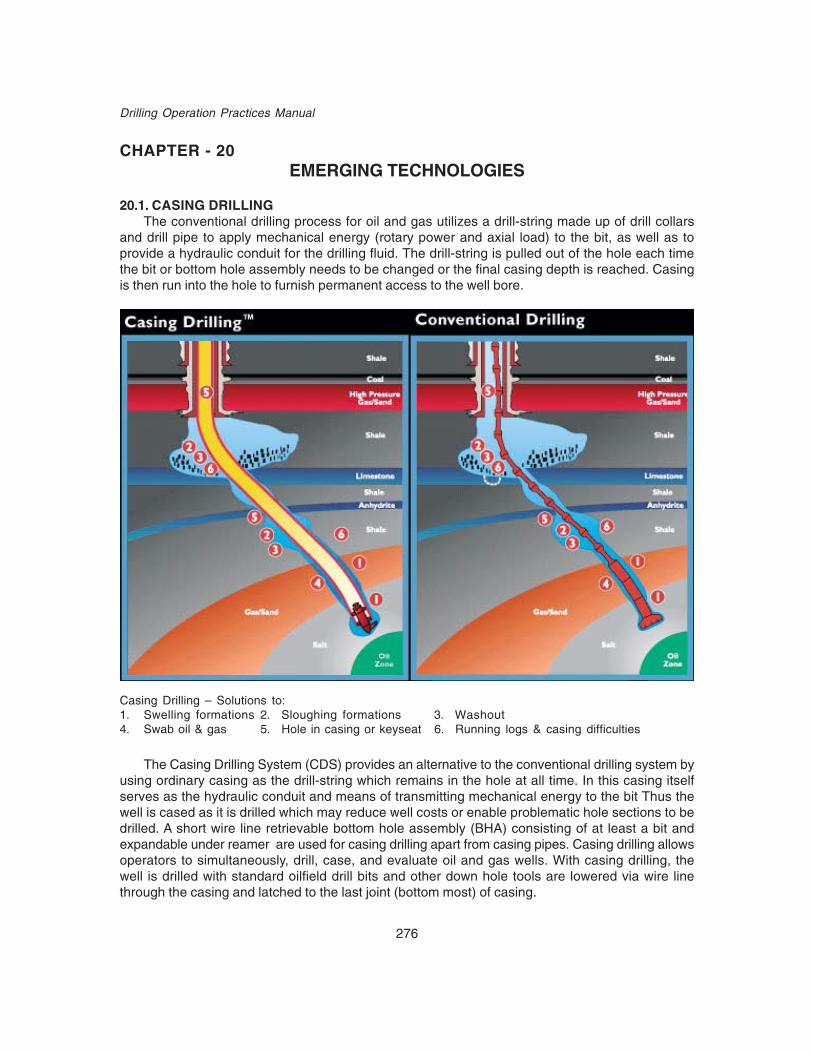
276
Drilling Operation Practices Manual
CHAPTER - 20EMERGING TECHNOLOGIES
20.1. CASING DRILLINGThe conventional drilling process for oil and gas utilizes a drill-string made up of drill collars
and drill pipe to apply mechanical energy (rotary power and axial load) to the bit, as well as toprovide a hydraulic conduit for the drilling fluid. The drill-string is pulled out of the hole each timethe bit or bottom hole assembly needs to be changed or the final casing depth is reached. Casingis then run into the hole to furnish permanent access to the well bore.
Casing Drilling – Solutions to:1. Swelling formations 2. Sloughing formations 3. Washout4. Swab oil & gas 5. Hole in casing or keyseat 6. Running logs & casing difficulties
The Casing Drilling System (CDS) provides an alternative to the conventional drilling system byusing ordinary casing as the drill-string which remains in the hole at all time. In this casing itselfserves as the hydraulic conduit and means of transmitting mechanical energy to the bit Thus thewell is cased as it is drilled which may reduce well costs or enable problematic hole sections to bedrilled. A short wire line retrievable bottom hole assembly (BHA) consisting of at least a bit andexpandable under reamer are used for casing drilling apart from casing pipes. Casing drilling allowsoperators to simultaneously, drill, case, and evaluate oil and gas wells. With casing drilling, thewell is drilled with standard oilfield drill bits and other down hole tools are lowered via wire linethrough the casing and latched to the last joint (bottom most) of casing.

277
Emerging Technologies
The Casing Drilling system simultaneously drills and cases a well with normal oilfield casingas the drill string. The casing transfers hydraulic and mechanical energy to a wire line-retrievabledrilling assembly suspended in a profile nipple located near the bottom of the casing. A drill lock(DLA) in the top of the drilling assembly provides mechanical (axial and torsional) coupling andhydraulic seals to the casing. It also provides a mechanism to facilitate insertion and retrieval fromthe casing string. The drilling assembly below the DLA terminates in a pilot bit and under reamerbut may include other conventional drill string components, such as a mud motor, coring assemblyand a directional assembly.
In most casing drilling applications, an under reamer is used above a pilot bit to open the holefrom the pilot-bit diameter to the final well bore diameter. The pilot bit is sized to pass through thecasing, and the under reamer opens the hole to the size that is normally drilled to run casing. Thecasing drilling system uses a top drive to rotate the casing. Single joints of casing are picked upoff the pipe rack and set in the mouse hole. The top drive, with an extend feature, is connected tothe top of the joint, which is then stabbed into the top of the casing string in the rotary table. Thecasing joint is drilled down by using the top drive in a conventional manner. The casing string isrotated for all operations except slide drilling with a motor and bent housing assembly for orienteddirectional work.
One of the most meaningful benefits of casing drilling is the reduction of down hole troubletime. By concurrently casing while drilling, lost circulation and well control incidents have beennearly eliminated thereby enhancing safety. This is particularly key for wells that encounter a weakzone prior to drilling into a higher-pressure zone. Balancing the required procedures for these differingzones has historically been a challenge that can be overcome through casing drilling.
The two basic technologies used for Casing Drilling are;1. The first technology employed by Tesco, uses a bottom hole assembly comprised of a
positive displacement motor (PDM), drill bit and hole opener / under reamer. The assemblyis latched to the first joint of casing. As the assembly drills ahead, the casing is loweredinto the hole, either in a static or rotated mode. The casing connections are normal buttressthread with Multi torque rings for additional torque resistance. Upon reaching total depth(TD), the latch-on bottom hole assembly is recovered with a special retrieval tool. A valvesystem is run and installed before cementing commences.
2. The second technology adopted by Weatherford, utilizes only casing to transmit rotary torqueand weight to the drill bit. A drillable drill bit and valve assembly is made up and run withthe first joint of casing. The casing string is rotated during drilling, typically with a spearassembly that provides rotation to the casing. Upon reaching TD, the casing can be cementedimmediately, with no need for an additional trip.
Advantages & Features of Casing DrillingReduces or eliminates drill pipe or wire line trip timesGets casing to design depth through problem formationsReduces potential requirement of contingency casingReduces the initial surface casing size, because it can go deeperDrills straighter holes reducing torque, drag and cleaning problems due to spiralingReduces open hole exposure time and associated drilling problemsReduces borehole exposure to formation and completion damageReduces or eliminates well control issues of DP trippingSimplifies well architecture

278
Drilling Operation Practices Manual
Optimizes reservoir productionPreserves well bore integrity.Eliminates use of Drill pipe, Heavy Weight Pipe. Also uses less bottom hole assembly tomake a complete Well. Thus saves the cost transportation, maintenance and inspection.Eliminates tripping and other pipe-handling which means reduced manpower requirementsand related safety incidents.Uses less horsepower required which translates into lower maintenance and lower fuel costsIncreases bit hydraulics due to smaller annular clearance.Lighter weight substructure and derrick means reduced capital and logistic costs.Lowers mud and cementing costs due to smaller well bore diameters.Less chances of mud loss even in weak formations due to smearing effect.Volume reduction for Drilling mud, completion fluids and cement slurry.Less drilling time and less completion time.Less drilling cost.
All this eliminates the need for;1. Reaming.2. Taking a kick while tripping the drill string.3. Unintentional sidetracks while reaming back into the hole.4. Hole problems caused by swab and surge pressures.5. Key seats and wearing holes in previously set casing.
Intangibile benefits of Casing Drilling technology.
Reduced Stuck PipeWorldwide experience shows that casing drilling drastically reduces stuck pipe ocurrances.
Formation Related Trouble Time Experienced With Conventional Rigs Is ReducedFaster completion of drilling reduces the exposure time. Elimination of tripping reduces
disturbance of formation.
Drilling safely through depleted zones – Smear / Plastering effectOne would normally expect lost circulation to be a potential problem with Casing Drilling because
the smaller annular clearance between the casing and borehole wall increases the frictional pressurelosses, thus increasing the ECD. In fact, what has been found is that Casing Drilling significantlyreduces lost circulation. There is substantive evidence that the Casing Drilling system can be usedto drill through weak depleted zones without the massive lost circulation that so frequently occurswhen drilling with drill pipe and collars. The exact mechanism that provides this benefit is not provedyet, but it is believed to be the result of mechanically working drilled solids into the face of theborehole. The axial misalignment of the casing that causes coupling wear also provides a constantmechanical force on the rotating couplings to smear drilled cuttings and mud solids into the boreholewall. This plastering effect mechanically builds an impermeable filter cake.
Improved Well ControlMany well control incidents occur while tripping pipe. These well control incidents are avoided
with the Casing Drilling process because pipe tripping is eliminated. But some kicks are takenwhile drilling ahead, and Casing Drilling will not prevent these.
Faster fishing Through Casing by Wire LineIt is possible to conduct conventional fishing operations to recover junk from the hole while
Casing Drilling. A fishing operation was conducted using conventional tools (mills, junk baskets,
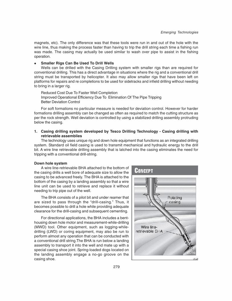
279
Emerging Technologies
magnets, etc). The only difference was that these tools were run in and out of the hole with thewire line, thus making the process faster than having to trip the drill string each time a fishing runwas made. The casing may actually be used similar to wash over pipe to assist in the fishingoperation.
Smaller Rigs Can Be Used To Drill WellsWells can be drilled with the Casing Drilling system with smaller rigs than are required for
conventional drilling. This has a direct advantage in situations where the rig and a conventional drillstring must be transported by helicopter. It also may allow smaller rigs that have been left onplatforms for repairs and re completions to be used for sidetracks and infield drilling without needingto bring in a larger rig.
Reduced Cost Due To Faster Well CompletionImproved Operational Efficiency Due To Elimination Of The Pipe TrippingBetter Deviation Control
For soft formations no particular measure is needed for deviation control. However for harderformations drilling assembly can be changed as often as required to match the cutting structure asper the rock strength. Well deviation is controlled by using a stabilized drilling assembly protrudingbelow the casing.
1. Casing drilling system developed by Tesco Drilling Technology - Casing drilling withretrievable assembliesThe technology uses unique rig and down hole equipment that functions as an integrated drilling
system. Standard oil field casing is used to transmit mechanical and hydraulic energy to the drillbit. A wire line retrievable drilling assembly that is latched into the casing eliminates the need fortripping with a conventional drill-string.
Down hole systemA wire line-retrievable BHA attached to the bottom of
the casing drills a well bore of adequate size to allow thecasing to be advanced freely. The BHA is attached to thebottom of the casing by a landing assembly so that a wireline unit can be used to retrieve and replace it withoutneeding to trip pipe out of the well.
The BHA consists of a pilot bit and under reamer thatare sized to pass through the “drill-casing.” Thus, itbecomes possible to drill a hole while providing adequateclearance for the drill-casing and subsequent cementing.
For directional applications, the BHA includes a bent-housing down hole motor and measurement-while-drilling(MWD) tool. Other equipment, such as logging-while-drilling (LWD) or coring equipment, may also be run toperform almost any operation that can be conducted witha conventional drill string.The BHA is run below a landingassembly to transport it into the well and mate up with aspecial casing shoe joint. Spring-loaded dogs located onthe landing assembly engage a no-go groove on thecasing shoe.
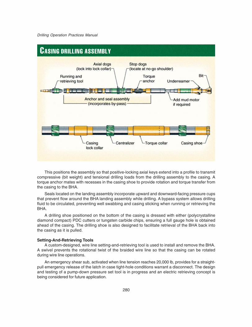
280
Drilling Operation Practices Manual
This positions the assembly so that positive-locking axial keys extend into a profile to transmitcompressive (bit weight) and tensional drilling loads from the drilling assembly to the casing. Atorque anchor mates with recesses in the casing shoe to provide rotation and torque transfer fromthe casing to the BHA.
Seals located on the landing assembly incorporate upward and downward-facing pressure cupsthat prevent flow around the BHA landing assembly while drilling. A bypass system allows drillingfluid to be circulated, preventing well swabbing and casing sticking when running or retrieving theBHA.
A drilling shoe positioned on the bottom of the casing is dressed with either (polycrystallinediamond compact) PDC cutters or tungsten carbide chips, ensuring a full gauge hole is obtainedahead of the casing. The drilling shoe is also designed to facilitate retrieval of the BHA back intothe casing as it is pulled.
Setting-And-Retrieving ToolsA custom-designed, wire line setting-and-retrieving tool is used to install and remove the BHA.
A swivel prevents the rotational twist of the braided wire line so that the casing can be rotatedduring wire line operations.
An emergency shear sub, activated when line tension reaches 20,000 lb, provides for a straight-pull emergency release of the latch in case tight-hole conditions warrant a disconnect. The designand testing of a pump-down pressure set tool is in progress and an electric retrieving concept isbeing considered for future application.

281
Emerging Technologies
Casing Drilling RigCasing drilling can be implemented either with a specially developed drilling rig or by a
conventional rig modified for casing drilling. To date, the system has been used only with a rigdesigned specifically to prove the entire system and to maximize the efficiencies of casing drilling.
Special equipment is needed to handle casing in a drilling mode and to handle the wire lineretrievable BHA. A top drive must be used to rotate the casing. In addition, a split crown and splittraveling blocks facilitate effective wire line access to the top of the casing through a wire line blowoutpreventor (BOP).
A large wire line unit is needed that is sufficient to run and pull the BHA efficiently. Pipe-handlingtools for the casing are also required.
Tesco has built three rigs that are hybrid casing-drilling and conventional-drilling rigs. A fourthis under construction, exclusively designed for use with the casing-drilling process.
In addition to the rig requirements mentioned above, these rigs include other features that allowthe entire drilling process to be implemented more effectively. The rigs are designed with hydraulicpower units for the mud pump, drawworks, top drive, and wire line unit, reducing equipment weightwhile taking advantage of the company’s top-drive design.
All this equipment is operated under computer control through programmable logic controllerinterfaces that minimize the potential for human operator error, optimize equipment performance,reduce manpower requirements, and facilitate data acquisition.
The wire line unit is installed as an integral part of the rig and is located adjacent to the maindrawworks. The hydraulic power and computer control allows the driller to function as the wire lineoperator from the driller’s control room. The hydraulic drive on the drawworks is very similar to thatshown for the wire line unit and acts as a brake that allows the drill string to be advanced with thedrawworks under power rather than with the power unit disengaged by a clutch.
The initial commercial applications of the casing drilling technology are anticipated to be appliedto relatively low-cost land wells. These wells are drilled rapidly, with frequent rig moves; consequently,the mobilization costs can be high. A number of features of the casing-drilling process allow for alighter rig design. The casing is picked up as single joints from the pipe rack. Thus, it does notneed the monkey board, setback area, and heavy derrick associated with a conventional rig. Theshorter and smaller derrick reduces wind load considerations, allowing for the construction of alighter derrick and substructure. Smaller mud pumps can also be used because larger casing IDssignificantly reduce the friction loss, as compared to conventional drill pipe and collars. Furthermore,the larger OD of the casing allows adequate annular velocity to be achieved with lower flow ratesthan otherwise achieved with drill pipe.
The overall result is that the rig:Is not as heavy to moveRequires less capital investmentUses less powerRequires a smaller crew.
Tesco’s patented Casing Drilling process could lower drilling time up to 30% and reduceunscheduled drilling events.

282
Drilling Operation Practices Manual
The Challenges associated with Casing Drilling are:
i. Changing The Bit Or Bottom Hole AssemblyCasing Drilling eliminates tripping as we know it and retrieve the down hole tools by wireline
through the casing. This will reduce trip time and eliminate the unscheduled events associated withconventional tripping. The down hole tools incorporate both an axial and torsional latching mechanismto anchor the tools to the bottom of the casing so drilling can proceed by rotation of the casing orthe use of a mud motor.
ii. Tubulars and Casing ConnectionsCasing used with retrievable casing system is generally of same size, weight and grade that
would normally be used in a well. However the casing connections may require a change becausecasing in this case has to provide adequate torsional strength, fatigue resistance and flow clearance.To achieve this buttress connections are used with multi-torque rings for additional torque capacity.Both integral and coupled connections have been used successfully.
iii. Drill Bits & Bit Cutting StructureDrilling with casing and wireline retrieving the tools would require that the cutting structure be
small enough to pass through the inside diameter of the casing, but have the ability to drill a largerhole size than the outside diameter of the casing. This is accomplished by using an under reamerbehind a smaller diameter pilot PDC bit.
iv. Centralization and stabilizationNo conventional cementing centralizers were found economical and rugged enough to withstand
the drilling forces and that could be attached to the casing without altering its performance. Solidcentralizers may need to be added to the casing for directional performance, wear management,key seat control and centralization for cementing. Both the issues have been tackled by installinghydro formed stabilizers and wear bands using crimping process.
v. Fluid RequirementCompared to conventional drilling operations, experience has shown that flow rates can be
reduced substantially in “casing drilling system”. As annular volume is reduced dramatically, holecleaning is improved due to higher annular velocities achieved, even with reduced flow rates. Cleaningthe hole more efficiently and removing cuttings faster aids in ECD reduction. However, higher annularvelocities and the resultant friction losses in the annulus increase the ECD. Each application mustbe evaluated to determine the balance that must be struck between flow rates to clean the bit faceand clear the annulus of cuttings, and ECD management. Once all factors have been considered,the proper flow rate and nozzle configuration can be selected.
An inherent benefit of drilling with casing is the “mono bore” annulus. Conventional drillingassemblies result in different annular velocities around each drill string component. This can leadto well bore erosion around drill collars and inefficient cutting transport around the smaller diameterdrill pipe. With casing as the drill string, the annular space along the entire well bore is virtuallyequal allowing the optimum hydraulics to be “dialed in” based on the fluid properties, cuttingsconcentration and flow rate. Hole cleaning ECD management and hole cleaning are much easier.Hole cleaning has not been an issue on previous wells. While no caliper log data is available, lagtime and cement returns do not indicate borehole enlargement to be an issue.

283
Emerging Technologies
vi. FishingIt is possible to conduct conventional fishing operations to recover junk from the hole while Casing
Drilling. A fishing operation was conducted using conventional tools (mills, junk baskets, magnets,etc). The only difference was that these tools were run in and out of the hole with the wire line, thusmaking the process faster than having to trip the drill string each time a fishing run was made. Thecasing may actually be used similar to wash over pipe to assist in the fishing operation.
vii. Logging/Formation EvaluationDrilling with casing requires that the well be cased as drilling commences. This prohibits logging
the open hole with conventional wire-line logging tools once the hole section is complete unlessthe casing is pulled above the zone and logged below the bottom. One solution to this problem canbe to log while drilling (LWD). Alternatively depending on what type of logs or what interval must belogged, cased hole logs can be run inside the casing or open hole logs can be run out the bottomof the casing to log intervals of interest. Other formation evaluation tools such as core barrels andtesting equipment can be adapted to the wire line retrieving tools and then used conventionallyonce latched into the casing.
The technique for running open hole logs that has been found most effective, is to drill to TDwith the final casing, release the bit, and then ream back to the previous casing shoe. The logs arethen run through the casing just as they would be if the well were drilled conventionally. Once loggingis completed, the casing is reamed back to bottom and cemented. This eliminates the need to tripall the way out of the hole and provides a way to continuously circulate the well in case it begins toflow.
viii. Cementing and Drilling Out the ShoeIn casing drilling, once the casing is drilled to the casing setting depth, the BHA is wire line
retrieved. The casing will not have a float collar to land the cement plug. To overcome this problem,the displacement plug must land and latch into the casing and serve as a float. The plug and cementin the shoe joint must then be drilled out with an under reamer and pilot bit assembly connected tothe next smaller size of casing.
ix. Directional ControlA limited amount of directional work with steerable motors for both deviation control and to a
planned target has been done with the 7-in. casing during the phase one and two trials. The directionalBHAs could be run and retrieved with the wire line without any difficulty. The directional drillingperformance was similar to the directional performance experienced when drilling at Lobo with drillpipe.9
x. Well ControlMany well control incidents occur while tripping pipe. These well control incidents are avoided
with the Casing Drilling process because pipe tripping is eliminated. But some kicks are takenwhile drilling ahead, and Casing Drilling will not prevent these.
xi. CoringCoring operations with casing can be conducted in two different ways:a) The first method involves running conventional core barrel (both inner and outer barrel)
and core bit below the DLA and using an under reamer above the core barrel to open thehole to the full dia. Core sample can be taken at any time and drilling can resume withlittle delay after coring.
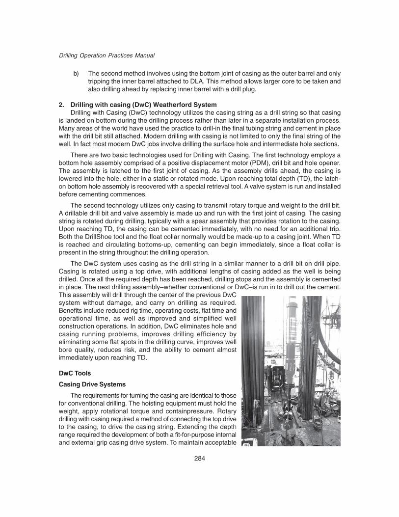
284
Drilling Operation Practices Manual
b) The second method involves using the bottom joint of casing as the outer barrel and onlytripping the inner barrel attached to DLA. This method allows larger core to be taken andalso drilling ahead by replacing inner barrel with a drill plug.
2. Drilling with casing (DwC) Weatherford SystemDrilling with Casing (DwC) technology utilizes the casing string as a drill string so that casing
is landed on bottom during the drilling process rather than later in a separate installation process.Many areas of the world have used the practice to drill-in the final tubing string and cement in placewith the drill bit still attached. Modern drilling with casing is not limited to only the final string of thewell. In fact most modern DwC jobs involve drilling the surface hole and intermediate hole sections.
There are two basic technologies used for Drilling with Casing. The first technology employs abottom hole assembly comprised of a positive displacement motor (PDM), drill bit and hole opener.The assembly is latched to the first joint of casing. As the assembly drills ahead, the casing islowered into the hole, either in a static or rotated mode. Upon reaching total depth (TD), the latch-on bottom hole assembly is recovered with a special retrieval tool. A valve system is run and installedbefore cementing commences.
The second technology utilizes only casing to transmit rotary torque and weight to the drill bit.A drillable drill bit and valve assembly is made up and run with the first joint of casing. The casingstring is rotated during drilling, typically with a spear assembly that provides rotation to the casing.Upon reaching TD, the casing can be cemented immediately, with no need for an additional trip.Both the DrillShoe tool and the float collar normally would be made-up to a casing joint. When TDis reached and circulating bottoms-up, cementing can begin immediately, since a float collar ispresent in the string throughout the drilling operation.
The DwC system uses casing as the drill string in a similar manner to a drill bit on drill pipe.Casing is rotated using a top drive, with additional lengths of casing added as the well is beingdrilled. Once all the required depth has been reached, drilling stops and the assembly is cementedin place. The next drilling assembly–whether conventional or DwC–is run in to drill out the cement.This assembly will drill through the center of the previous DwCsystem without damage, and carry on drilling as required.Benefits include reduced rig time, operating costs, flat time andoperational time, as well as improved and simplified wellconstruction operations. In addition, DwC eliminates hole andcasing running problems, improves drilling efficiency byeliminating some flat spots in the drilling curve, improves wellbore quality, reduces risk, and the ability to cement almostimmediately upon reaching TD.
DwC Tools
Casing Drive Systems
The requirements for turning the casing are identical to thosefor conventional drilling. The hoisting equipment must hold theweight, apply rotational torque and containpressure. Rotarydrilling with casing required a method of connecting the top driveto the casing, to drive the casing string. Extending the depthrange required the development of both a fit-for-purpose internaland external grip casing drive system. To maintain acceptable

285
Emerging Technologies
load forces for extended lengths of casing, the slip area of the internal grapples was significantlyincreased to spread the forces over a larger area. The tool is designed for quickly connecting in thecasing to minimize connection time. A stop ring is positioned near the top of the spear to ensurethe grapples are engaged in the proper location inside the casing. A simple quarter turn to the rightengages the spear to hold the casing string and apply rotational torque. A quarter turn to the left,without axial load, releases the tool. Pumping energizes the packer element. A mud saver valvecan be incorporated to minimize spillage on connections.
Drilling With Casing BitsThe leading component in this stepchange technology is the Weatherford DrillShoe drillable
casing bits. Weatherford has introduced a range of proprietary drillable bits for casing drillingapplications that are made up directly onto casing.
These casing bits have been designed to emulate the standard features of conventional drillbits in a drillable package. DrillShoe I and DrillShoe II have now led to the innovation of a thirdgeneration, DrillShoe III. DrillShoe I is designed for drilling very soft to soft unconsolidated rock,typically surface hole, in sizes ranging from 95/8 to 20 inches. Benefits include rapid and damage-free drill out, and suitability for applications with standard buttress or premium casing connections.DrillShoe II is for consolidated formations. Features include PDC cutters along with a proprietarydiamond cutting structure, the ability to run on most standard casing and liner drilling systems,and interchangeable drillable nozzles that optimize performance. Sizes range from 5 to 20 inches.The cutting structure’s design in the first two generations is a balance between the need to drillahead and the requirement for the cutting structure to be subsequently drilled out.
DrillShoe III, meanwhile, features a PDC cutting structure mounted on displaceable blades. Oncethe casing string has been drilled to TD, a ball is dropped that seals off the flow path, resulting in apressure increase that forces the inner piston downward, displacing the PDC cutting blades intothe annulus. Cementing ports on the inner piston are exposed once the blades are completelydisplaced. It is designed for more competent formations and longer drilling intervals. The third-generation DrillShoe combines the benefits of a PDC cutting structure with the ability to displaceits nondrillable cutting structure into the annulus, leaving only drillable materials in the path of thefollowing drill string.
Shown in both closed (left) and expanded (right) positions, this expandable bit is one of the newestadvances in drilling with casing technology. It incorporates many of the features of a standard PDC bit whiledrilling a 40 percent largaer hole, and is designed to replace a conventional hole opener.

286
Drilling Operation Practices Manual
Weatherford customers have set more than 400 casing strings with the DwC system in sizesfrom 51/2 to 20 inches.
Drilling with Liners (DwL)Liner drilling systems have been used for penetrating high pressured formations into deeper
depleted zones. Liner drilling extends casing points in environments where pressure gradients areincreasing with depth. The practice should be considered an alternative for reducing trouble timeand reaching objectives in critical, narrow-margin wells. The concept relies on managing annularfluid pressure around the large-diameter liner to create favorable equivalent circulating density (ECD)profiles that allow penetrating farther into narrow pore pressure-fracture gradient windows. However,as liner drilling proceeds beyond normal limits, risks must be managed for making drillingconnections, liner cementing and maintaining well control. The approach is consistent with ongoingindustry focus on managed-pressure drilling using conventional drill-strings.
In this concept, the hole is drilled - with a conventional drillstring - to traditional well controllimits, e.g., a kick tolerance limit. The drill-in liner is then run, mud weight is reduced and drillingcontinues. In some circumstances, this concept may allow significant extra interval to be drilledbeyond conventional limits, thus increasing the chances of reaching deeper objectives. Other benefitsinclude reduced stuck pipe consequences and added capability to kill underground blowouts. Theliner drilling process results in installation of full-strength tubulars in the well. Liner drilling may alsobe used prior to reaching conventional casing points to mitigate cyclic fluid losses and fluid gains(ballooning effects) that often plague narrow-margin drilling.
Weatherford is the world leader in rotating liner systems, holding records for the longest rotatingliner installed (18,233’,) and the heaviest liner run (782,775 lbs.)
Applications for Drilling with Liners include:Depleted formationsUnstable formationsLoss zonesPressure zonesSalt dome drillingMoving/swelling formationsExcessive hole cavings
Future Developments/ApplicationsDeep Water ApplicationsUnder Balance DrillingUse Of CWD With Air DrillingUse Of Single String Of Casing From Surface To TDThe Ultimate Drilling Solution May Be A Combination Of Casing Drilling With ExpandableTubulars
Deep Water DrillingA tight operating window between fracture and formation pressure characterizes most deepwater
drilling. The consequence is that as many as seven, eight, or more, casings may be needed toreach deep drilling objectives. Industry has become adept at managing the balance of mud weight,equivalent circulating density (ECD), trip margins, lost circulation material treatments and otheroperational aspects to try to push the casing points. However, this balance is difficult, and problemsoccur frequently.

287
Emerging Technologies
Deep Water wells are inherently expensive. However, when problems occur, they can beextensive, and cost overruns commonly approach 50% and more.
With the introduction of Casing Drilling lost circulation, stuck pipe and well control issues haveall but disappeared on wells. This was an unexpected benefit, but clearly one that has tremendouspotential in the deepwater environment.
Directional Casing DrillingVertical wells can sometimes be drilled with casing using a simple system consisting primarily
of a special bit attached to the casing that can be drilled out to run subsequent casing strings.But when there is a need to drill with a motor without rotating the casing or the section cannotconfidently be drilled with a single bit, then a retrievable drilling assembly that can be recoveredand re-run is required. Even some sections that can be drilled with a drill-out bit may be more costeffectively drilled with a retrievable system. A retrievable Casing Drilling system is required fordirectional wells because of the need to recover the expensive directional drilling and guidance tools,the need to have the capability to replace failed equipment before reaching casing point, and theneed for quick and cost effective access to the formations below the casing shoe.
Casing Drilling of directional wells provides a practical alternative to drilling the wellsconventionally and then running the casing as a separate process. It assures that the casing canbe run to TD and it captures many of the savings that have been proven while Casing Drilling verticalwells. For larger sizes of casing, no loss of efficiency occurs while drilling with the steerable toolsbelow the casing. This allows the operator to take full advantage of the faster tripping and troubleavoidance benefits provided by Casing Drilling. Tesco typically pulls the BHA with a wireline unit,but this will require a higher capacity wireline unit when a directional assembly is used in the largercasing sizes. Directional drilling with smaller size casing may sacrifice some drilling efficiency dueto the requirement to use smaller motors and is most advantageously applied in situations wherethe Casing Drilling system provides an enabling technology rather than an improvement in efficiency.
Underbalanced and Air Casing DrillingCasing Drilling also seems to have application for drilling in under balanced situations. One of
the next goals for the Lobo development is to try to eliminate a string of casing by drilling fromsurface casing to TD with one string of pipe instead of two. This may be accomplished by drillingwith a rotating head so the deeper zones can be drilled with a much lighter mud weight than iscurrently used. An obvious advantage to under balanced drilling with casing is that the well doesnot have to be balanced with heavy mud to trip out of the hole to run casin, as would be requiredwith a conventional system.
Wells can be drilled with the Casing Drilling system with smaller rigs than are required forconventional drilling. This has a direct advantage in situations where the rig and a conventional drillstring must be transported by helicopter. It also may allow smaller rigs that have been left onplatforms for repairs and recompletions to be used for sidetracks and infield drilling without needingto bring in a larger rig.
There are also potential applications that require a little more development. Equipment to allowthe Casing Drilling system to be used while air drilling is under development and modifications tothe system to allow it to be used in deep water applications are in progress. The ultimate drillingsolution may be a combination of Casing Drilling with expandable tubulars, but there are severalhurdles that must be overcome for this to be practical.

288
Drilling Operation Practices Manual
Use Of CWD With Under Balanced Drilling -Advantages
1. Safer than UBD with Drill pipe (no tripping of drill string)2. Can eliminate intermediate strings of casing3. Drills faster.
Result1. Improved production2. Reduced time on location3. Saves money.
Use Of CWD With Air Drilling –Advantages
1. Reduced compression demand2. High annular velocities3. improved tolerances for water influxes4. Improved penetration rates5. Reduced mud ring build up
Result1. Ability to drill deeper on air2. Use less horse power to drill.
ConclusionsThe conclusion drawn from initial CWD test wells suggest cost savings of 10-15% for trouble
free wells. Elimination of unscheduled events encountered in trouble some wells may increase savingsup to 30% or higher.
Casing Drilling eliminates all the costs associated with these down hole problems:Swelling Formations Sloughing Formations Washouts Swabbing Hole in Casing or Key Seats Running Logs and Casing
Casing drilling, an innovative process for simultaneously drilling and casing a well, is emergingas viable technology for the 21st century. Field studies have demonstrated a 20 - 30% reduction inthe time required to drill wells from spud to rig release when utilizing casing drilling.
1. As on date it is mainly used for following categories of wells-Top Hole Sections: Conductor and Surface CasingTrouble Zones: Drilling LinersDirectional Sections: Intermediate and Production Casing
2. In ONGC, especially in Geleky area of Upper Assam Asset where wells of depth more than4000m are taking too long for completion due to one or the other problem, this technology can betried in 2-3 wells to test whether this can reduce cycle time and reduce the cost of drilling . Althoughcost is slightly on higher side but may helps us in completing our 8 ½” section in 45 days.

289
Emerging Technologies
20.2 EXPANDABLE CASINGThe fundamental concept of expandable casing is cold-working steel tubulars to the required
size downhole. This process, when exactingly controlled, can be mechanically preformed in a downhole environment. Many technical and operational hurdles have to be overcome when using cold-drawing processes in a downhole environment.
Solid expandable systems are solid steel jointed pipe that are run in the hole as normal casingand expanded downhole to a pre-determined OD and ID. Once the system is expanded, the entiresystem will withstand expected collapse and yield pressures.
Once the solid expandable system is put on depth, an expansion cone, called launcher, whichis placed inside the first casing joint, is used to permanently mechanically deform the pipe (fig. 1).The cone is moved through the expandable string by a differential hydraulic pressure across thecone area, by a direct mechanical pull or push force, or by a combination of both.
Solid expandable tubular technology provides feasible options for drilling, completion, andworkover operations allowing operators to reach previously unattainable target zones. Solid expandabletubular (SET) installations have increased production, extended production life through remediationof existing pay zones, and provided the ability to reach target depths.
In a drilling application, solid expandable tubular technology reduces the telescopic effect createdby using multiple casing strings in deepwater or extended reach wells, thereby preserving valuablehole size. Deepwater operators, who were the drivers of solid expandable tubular (SET) technology,will be tremendously benefited from this technology. Since its development, the technology hasrapidly moved from the deepwater, to a technology that has been embraced by operators in manybasins. At present only 22% of the installations have been in deepwater, with over 65% of the totaljobs having been done on land.
In 1998 an autonomous new company M/s Enventure Global Technology was formed by ShellTechnology Ventures Inc. and Halliburton Energy Services to develop and commercialize expandablecasing technology.
System DetailThe differential pressure required for tubular expansion is created by pumping through an inner-
string that is connected to the cone. The hydraulic force acts across the bottom side of the conearea forcing it upward. Mechanical force is applied by either raising or lowering the inner-string(fig. 2). The progress of the cone through the expandable tubular string deforms the steel beyondits elastic limit into the plastic region, while keeping stresses below ultimate yield (fig. 3). Expansionsgreater than 20%, based on the ID of the pipe, have been accomplished in lab. Most applicationsusing 4-1/4 in. to 13-3/8 in. tubulars have required expansions less than 20%.
Expandable technology is seen as a means of reducing the overall cost of a well and its supportinfrastructure. The application of the technology within the first ten years has been aimed mainly atthose well bore construction techniques that have remained unchanged for decades. Telescopingcasing designs have existed since the very first wells and reservoir completion practices haveremained stagnant, dominated by gravel packing. The basic design of liner hangers, packers andthrough tubing straddles has not changed either; expandable technology will, and already hasrevolutionized techniques in these areas.
Expandable Casing Technology will enable oil and gas operators to access reservoirs that cannotbe easily reached with current methods. By expanding casing in situ, the hole size can bemaintained and the target reached with minimal well tapering. This results in improved reservoir

290
Drilling Operation Practices Manual
economics by reducing well capital expenditures and improving the success rate of reaching subsalt targets. In addition to rig-time savings and lower well costs, expandable casing technology canresult in overall smaller hole size from spud to total depth. Expandable casing offers the potentialfor a step change in well construction technology.
Enventure’s expandable-tubular systems address numerous drilling and completion challengesand can especially enhance deepwater operations, one of the industry’s highest priorities. The choiceof comparatively larger final hole sizes that expandable-tubular technology allows can provide accessto previously unreachable reservoirs; it can also reduce drilling time and the size of drilling equipment,including lay-down areas and auxiliary equipment required on offshore platforms. In operators’ bottom-line terms, expandable-tubular systems should lower overall project costs.
Expandable tubular technology has found many applications such as:Expandable solid casing that allows the construction of a mono-diameter borehole or functionas borehole liners that permit the drilling of larger diameter boreholes.Expandable perforated or slotted pipe for lining the producing zone.Expandable legs of Level 6 multilateral junctions that permit the drilling of larger-diameterlaterals while maintaining pressure integrity with the junction.Expandables for use as liner hangers.Expandable liners for repairing casing
SET SystemsSolid expandable tubular technology has evolved over the past few years from a radical solution
for drilling challenges to a logical well construction process. By incorporating expandable systems
Fig. 2. Differential pressurepumped through the inner-string.
Fig. 3. Stress/strain curve for solidexpandable tubular systems.
Fig. 1.

291
Emerging Technologies
in the initial well design stage, the downhole tapering effect is reduced or eliminated. Enventure’sSET product line consists of three basic systems:
1) The Expandable Openhole Liner (OHLTM),2) The Expandable Cased-Hole Liner (CHLTM) and the3) Expandable Liner Hanger (ELHTM).
In addition to the above the technology also includes the following:openhole cladding systemmonodiameter system
Openhole Liner SystemsThe openhole liner system consists of expandable casing strings planned into the well
construction to minimize the telescoping effect of the original pre-expandable well designs. Solidexpandables minimize well slimming while adding strings for deeper depth.
This slimwell application can lower costs by reducing the following:mud volumessteel consumption per wellformation cuttings hence less threat of pollutionsize of the rig required to drill the well especially in deepwater applications
The openhole system can be used as a contingency drilling liner in any well during the drillingphase. Running this drilling liner maintains hole size when an unforeseen geologic anomaly or problemis encountered. These anomalies and problems can include the following:
unstable formationover- or under-pressured formationloss circulationpore pressure/fracture gradient
Having to install an unplanned casing string because of an unforeseen geological anomaly willno longer be detrimental to the well. The only limiting factor to achieving the target is temperatureand well geometry constraints. Ultra long-reach horizontal wells will be possible where an entirefield can be produced from a single drilling pad, platform, or subsea template.
Wellbore extensions can be accomplished by using an existing non-producing well. A windowcan be cut and an expandable system could be run to re-direct the well to another target.Thisexpandable application maintains hole size to allow a larger liner to be run into the pay zone. Anexample would be to cut a window in a 9-5/8 in. existing casing and run a 7-5/8 x 9-5/8 in. expandablesystem. Once expanded, this system would allow for a 7-5/8 in. special clearance coupling liner tobe run into the producing zone.
The window exit installation involved expanding an Openhole Liner System below the window,allowing the operator to maintain hole size to total depth. This capability increases the range ofapplications for the OHL System in sidetracks in existing casing.
Cased-hole Liner SystemThe expandable cased-hole liner system enables operators to repair existing damaged or worn
casing for deeper drilling or other contingencies. The system makes it possible to upgradeexploration-grade casing to a sturdier production casing with minimal loss of casing ID.
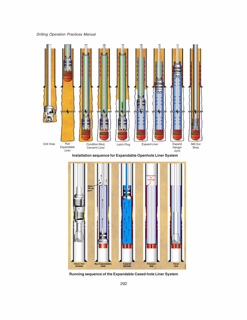
292
Drilling Operation Practices Manual
Installation sequence for Expandable Openhole Liner System
Running sequence of the Expandable Cased-hole Liner System
Drill Hole RunExpandable
Liner
Condition Mud,Cememt Liner
Latch Plug Expand Liner ExpandHangerJoint
Mill OutShoe

293
Emerging Technologies
The cased-hole liner system is mechanically similar to the expandable openhole liner systemexcept that an additional anchor-hanger joint (elastomer section) is located immediately above thelauncher assembly. Expanding this system inside existing casing repairs and reinforces the largercasing for completion.
The system can be used to shut off perforations in production casing for re-completion or fordeepening the well. This expandable system allows for enhanced control of existing injectors andproducers by shutting off unwanted gas or water production. The system has also been used to re-connect a severed wellbore due to subsidence from formation movement.
Expandable Liner Hanger SystemThe ELH System provides a much simpler and cost effective alternative to complex conventional
liner hangers and liner top packers. Enventure’s Expandable Liner Hanger, with no moving partssuch as slips, sleeves or O-rings, combines the functional requirements of a liner hanger and linertop seal, while minimizing the need for liner top squeezes. The ELH System simplifies the mechanicaland pressure functionality into a single unit, and eliminates possible leaks in the annulus duringsetting and for the life of the hanger. Additional savings are realized by eliminating the need for aseparate trip to install the liner top packer or to test the liner top.
Running sequence of the Expandable Liner Hanger System

294
Drilling Operation Practices Manual
In addition to the above the following products have also been developed by Enventure
1. FlexClad™ SystemEnventure’s FlexClad System repairs existing casing, isolates perforated sections and provides
a gas-tight liner. This system consists of expandable sealing sections called Flex Hangers,conventional API tubulars that act as spacer joints and flush joint connec-tions. The Flex Hangersare separated along the length of the liner using spacer pipe, enabling this system to be used insmaller casing sizes. The FlexClad System differs from Enven-ture’s standard expansion systemsin that the liner and connections are not expanded.
2. Openhole Cladding SystemThe openhole cladding system is an expandable string that is run and installed in the open
hole to address the following:isolate an unstable formationisolate a water flowshut off water influx in a openhole completion
The openhole cladding system installation process is similar to that of the openhole liner withthe exception that it is not tied back into the base casing. Elastomers are configured to seal againstthe formation. The seal efficiency will be a function of the rock properties where it is set. Porosity,permeability, and rock hardness all affect the seal capabilities.

295
Emerging Technologies
3. Monodiameter SystemMonodiameter technology is currently in the final field-testing stage and already generating results
that are impressive and revolutionary. This technology consecutively runs the same size expandablecasing strings and expands them into each other to achieve the same ID from top to bottom. Themonodiameter removes the telescoping effect of pre-expandable well design
System Specifications -a. Material: Today, standard oilfield tubular steel is used for Solid Expandable Tubulars after it issubjected to a special heat-treating process to increase ductility, which allows the steel to be pushedtemporarily into the plastic region during expansion, reduce defect sensitivity and increase fracturetoughness. The Solid Expandable Tubulars currently in use are ERW (electric resistance weld)seamed pipe, custom-made by Lone Star Steel to high specifications developed by Enventure. Thespecifications, particularly for wall thickness variation of the pipe, are much stricter than for typicaloilfield tubulars. For example, the American Petroleum Institute allows a 12.5% variation in the wallthickness of standard oilfield tubulars. Depending upon pipe size, Enventure’s requirements allowonly a 5% to 7% variation in wall thickness.
b. Sizes Available As on date the SET systems are available in following sizes-13 3/8" X 16"11 ¾” X 14 ½”9 5/8" X 117/8"OR 11 ¾”8 5/8" X 10 ¾”7 5/8" X 9 7/8"5 ½” X 7 5/8"6" X 7 5/8"5 ½” X 7"4 ¼” X 5 ½”
Note: 7 5/8" X 9 5/8" - Means7 5/8" is the size ( OD) of SET casing pre expansion and9 5/8" is the size (O.D.) of base casing against which SET will be expanded
Further 7 5/8" becomes the ID for the next well section after expansion.
c. Expansion Ratios: Normal expansion ratios of SET expandable tubulars are in the range of10-15% but it can be expanded even upto 20-25 % for mono-diameter casings. On expansion theO.D of SET casing increases thereby decreasing (shortening) its length by approx. 4%.
This technology has proved its worth in maximizing production through bigger production casings/strings, well deepenings, reaching deeper depths with higher casing sizes and as a contingencycasing for deep water wells where lot of casing strings are required due to narrow margin betweenpore pressure and fracture pressure.
By reducing telescopic nature of wells, many additional benefits are expected in near futureBy reducing casing size, BOP and Riser size can be reduced in Deep water wells. Thiswill reduce the rig cost dramatically and so also well cost.Land rig size will also be reduced thus reducing foot print and emission.Producing less waste (cuttings) because smaller wells produces up to 50% less cuttingsand hence less environment damage.Less mud chemical costLess steel consumption per well

296
Drilling Operation Practices Manual
Once mono diameter well completion becomes feasible it will further reduce time and cost forwell completion by-
1) Standardization of tools2) Fewer BHA make up / break out3) Higher operating efficiency4) Higher safety since bigger sizes of casing will be avoided and fewer BHA’s to be handled .
This technology was successfully used in ONGC, in 2 wells in Mumbai offshore recently(Oct-Dec 2003). In one well it was used to tap deeper oil layer from an existing well and in other as acontingency casing to attain desired production casing size. Based on its performance 30 morewells are being completed using this technology in the year 2006-07.
Presently its cost is on the higher side, hence it is more suited in offshore where productionrates are higher and well costs are more but it can be hoped that with the passage of time it willbecome highly cost effective for less producing fields as well.
Application of the Expandable TechnologyAlthough expandable products are unique, and interesting in concept and installation, they have
little value if cost-effective applications cannot be realized from their development. The economicsof expandable tubulars must work for the long-term benefit of operators. As costs decline, the impacton all aspects of well operations is expected to increase dramatically.
There is a multitude of applications for this technology, including applications for products foroptimizing surface facilities, sub-sea equipment as well as sub-surface products. The application ofthe technology in the subsurface environment has the potential of significantly reducing surfaceand subsurface costs and increasing the return on investments (ROI) of the operating companies.
This technology enables the operator to “reach through” deepwater subsurface environment justunder the mud line containing shallow water flow, rubble zones, etc. which require so many casingpoints. The use of Expandable Openhole Drill Liners in such cases can give the operator severaladditional strings of casing above those listed in the casing catalogs This will enable them to reachtheir objectives, and will not require the premature plugging of wells costing millions of dollars. Theopenhole system can be used as a contingency drilling liner in any well during the drilling phase.Running this drilling liner maintains hole size when an unforeseen geologic anomaly or problem isencountered. These anomalies and problems can include the following:
unstable formationover- or under-pressured formationloss circulationpore pressure/fracture gradient
Having to install an unplanned casing string because of an unforeseen geological anomaly willno longer be detrimental to the well. The only limiting factor to achieving the target is temperatureand well geometry constraints. Ultra long-reach horizontal wells will be possible where an entirefield can be produced from a single drilling pad, platform, or subsea template.
Wellbore extensions can be accomplished by using an existing non-producing well. A windowcan be cut and an expandable system could be run to re-direct the well to another target. Thisexpandable application maintains hole size to allow a larger liner to be run into the pay zone. Anexample would be to cut a window in a 9-5/8 in. existing casing and run a 7-5/8 x 9-5/8 in. expandablesystem. Once expanded, this system would allow for a 7-5/8 in. special clearance coupling liner tobe run into the producing zone.

297
Emerging Technologies
Discussion of Deepwater ApplicationsExpandable casing technology can provide value in deepwater well engineering operations in
two areas:1. An enabling technology for low drilling margin conditions2. A cost-effective solution in conjunction with smaller rigs in deepwater
As operations move into deeper water, drilling margins (the difference between pore pressuregradient and fracture-pressure gradient) become narrower. This results in more casing strings requiredto drill to an equivalent depth below the mudline compared to a well drilled in a shallower waterdepth.
In some cases, using conventional casing programs with an 18-3/4 inch BOP stack and a 21-inch OD drilling riser, well objectives cannot be reached with a sufficiently large hole size for evaluationand production operations. Figure below illustrates a sample ultra-deep water well, located in morethan 5,000 feet of water, that reached its objectives by using a 13-3/8 inch by 16-inch SET system.SET technology can also be used to provide contingency casing deeper in the well.
Ultra-deepwater well using a 13-3/8 inch X 16-inch SET System
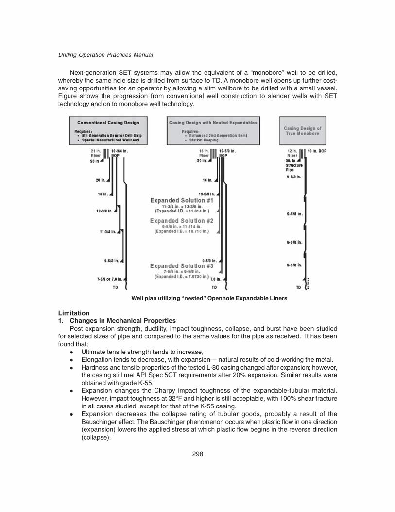
298
Drilling Operation Practices Manual
Next-generation SET systems may allow the equivalent of a “monobore” well to be drilled,whereby the same hole size is drilled from surface to TD. A monobore well opens up further cost-saving opportunities for an operator by allowing a slim wellbore to be drilled with a small vessel.Figure shows the progression from conventional well construction to slender wells with SETtechnology and on to monobore well technology.
Limitation1. Changes in Mechanical Properties
Post expansion strength, ductility, impact toughness, collapse, and burst have been studiedfor selected sizes of pipe and compared to the same values for the pipe as received. It has beenfound that;
Ultimate tensile strength tends to increase,Elongation tends to decrease, with expansion— natural results of cold-working the metal.Hardness and tensile properties of the tested L-80 casing changed after expansion; however,the casing still met API Spec 5CT requirements after 20% expansion. Similar results wereobtained with grade K-55.Expansion changes the Charpy impact toughness of the expandable-tubular material.However, impact toughness at 32°F and higher is still acceptable, with 100% shear fracturein all cases studied, except for that of the K-55 casing.Expansion decreases the collapse rating of tubular goods, probably a result of theBauschinger effect. The Bauschinger phenomenon occurs when plastic flow in one direction(expansion) lowers the applied stress at which plastic flow begins in the reverse direction(collapse).
Well plan utilizing “nested” Openhole Expandable Liners

299
Emerging Technologies
2. CostThe cost of using SET technology is at present towards higher side but with increase in number
of applications and entry of more companies in production the cost is bound to come down as ithas been recognized as a safe, efficient and reliable technology for
Deep watersSub salt environmentsDepleted reservoirs
3. API casing with very strict controls specification only to be usedAt present restricted to two grades of casing only i.e. L-80 and K-55,Presently Lone Star Steels is the only manufacturer of casing pipes.
4. In case of stuck upExpanding a liner through a differentially stuck section dramatically changes the stress conditions
created by the expansion cone in the pipe, it can cause pipe damage and even rupture the expansionface. To reliably expand steel pipe beyond its elastic limit, it is necessary to maintain a displacement-controlled expansion process, and thus uniform hoop stress distributions on the expansion coneface. If pipe is differentially stuck, this places geometrical constraints on the liner, drill string andbottom hole assembly (BHA). If the magnitude of the differential pressure is small, the drill pipeand expansion cone will free up the stuck pipe and expansion can be continued safely. However, ifthe pressure differential is large enough, the liner cannot be freed. Geometrical constraints causesevere bending in the BHA and a large additional rotational moment is applied to the expansioncone. This moment causes concentration of hoop stress on the expansion face, loss of displacementcontrol and potential rupture of the liner.
Modifications have been done to the standard BHA, which reduce the risk of becoming stuck,free up constrained pipe and/or enable expansion through the stuck interval without causing hoopstress concentration. Operational procedures have been revised to minimize this potential risk.
ONGC Experience
SDST horizontal well IA#4ZH (Rig Sagar Shakti)On December 8, 2003 ONGC completed the first successful field application of 5 ½” X 7" size
solid expandable open hole liner in LIII B layer side tracked horizontal well 1A-4ZH. It was used asan extension of 7" liner base casing from the top of LIII reservoir to the top of B layer (landingpoint). Directional 6 1/8" pilot hole was drilled with motor& MWD from 1864m (angle 71.5°) to 2105m(angle 88°) up to top of B layer using gel polymer mud system. Enlarged 6 1/8" hole to 7" using 6"x 7" Near Bit Under Reamer (NBR) and watermelon mill (6.2" size) prior to lowering expandablecasing. In this phase 8.6 ppg gel polymer mud was used.
51/2 “ X 7” expandable open hole liner (OHL) of 290m length was run down hole through theexisting 7" base liner to a depth of 2101 m keeping Elastomer hanger top at 1811m. After cementing,the plug was bumped at a pressure of 2650 psi. The expansion process occurred at propagationpressure of 3700-4000 psi, and maximum 4500 psi when the hanger joint was expanded against 7"base casing. Expansion was performed in about 8 1/2 hrs. 500 m of 6" drain hole with 5"X 6" Bi-centric bit, MWD and Motor assembly was drilled from 2101m to 2600m within B layer using nondamaging clay free mud.
The well flowed @ 686 bopd.

300
Drilling Operation Practices Manual

301
Emerging Technologies
SET as a “Remedial measure” in SP#8H well (Rig Pride West Virginia)On January 2, 2004 second 5 ½”X 7" Expandable open hole liner (OHL) was safely installed in
horizontal development well SP-8H (clamp-on location). The well, which was planned to be completedas a horizontal in A2VII layer ran into unexpected down hole complications. 9 5/8" casing wasshort landed by 110m above top of LIII reservoir due to tight hole conditions. Conventionally, 9 5/8"casing would have set on LIII top but the held up resulted in premature loss of hole size. The 7"base casing liner had to be set pre-maturely above LIII top instead of A2 VII layer landing point. Toremedy the situation. 5 ½”” X 7" Expandable casing was incorporated in the drilling plan as a remedialmeasure for preserving hole size in order to achieve the desired objective of placing the 6" lateralsection within A layer.
The directional hole section of 150m length was drilled in Llll reservoir with a 6" x 7" bi centricdrill bit from 2351m (Llll top) to 2501m (A2 VII layer landing point). A Clean out trip was made withstabilizer, near bit reamer (NBR) and watermelon mill. 51/2"X 7" Expandable OHL system over aninterval of 192 m ranging from 72° to 87.7° angle was run to the depth of 2501m with Elastomerhanger top at 2309 m. The liner was expanded 11.8% in to 7" base casing and open hole in about4 hrs using Propagation pressure of 4500 to 6000 psi. The post expansion liner length was 185mresulting in 3.7% decreases in the over-all length. Two 6" lateral sections of 400 m each were drilledusing bi-centric bit and MWD in A2 VII layer of LIll reservoir.
The well flowed at a rate of 1050bopd
Recent Trends in Expandables
I. MonoDiameter TechnologyThe ultimate objective of the MonoDiameter System, the next generation of solid expandable
tubular (SET) technology that Enventure Global Technology and Shell has developed, is to makepossible a well with the same internal casing diameter from surface to total depth. This system willsave significant amounts of time and money by reducing flat time during drilling operations, using asmaller BOP stack, and standardizing equipment such as drillstrings and bits as well as casing.Safety will be enhanced because rig crews will not have to handle large diameter casing and drilling

302
Drilling Operation Practices Manual
equipment, and the frequency of changing out drilling equipment and bottomhole assemblies willbe minimized. Smaller, less expensive rigs can be used, especially in deep-water in conjunctionwith smaller riser, helping to dramatically reduce daily rig costs.
A well drilled using this system will have no diameter loss with each new liner. This means thatregardless of unexpected reservoir challenges, each well drilled can potentially reach its reservoirwith a casing size that will enable reservoirs to produce at full potential.
Nesting an expandable system inside an already expanded system preserves crucial hole size,which ultimately results in savings on bits, steel, mud and cement, as well as the storage spacerequired for these materials. Offshore, additional savings materialize in onboard drilling vessel storagerequirements because a smaller riser can be used. Reducing the amount of drill cuttings decreasesthe cost of cuttings disposal, a significant cost in offshore operations, especially when drilling witha zero-discharge requirement. Applying SlimWell Technology over a multi-well program cansubstantially impact the bottom line.
While SlimWell reduces the telescoping effect in traditional well design, the MonoDiameterSystem eliminates telescoping, allowing operators to slim down the top of the well while increasingthe well diameter at TD. A hybrid well is one that features conventional casing for the first three orfour strings and then moves to a series of MonoDiameter liners.
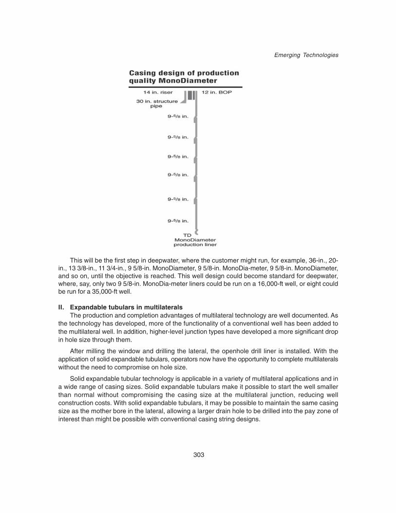
303
Emerging Technologies
This will be the first step in deepwater, where the customer might run, for example, 36-in., 20-in., 13 3/8-in., 11 3/4-in., 9 5/8-in. MonoDiameter, 9 5/8-in. MonoDia-meter, 9 5/8-in. MonoDiameter,and so on, until the objective is reached. This well design could become standard for deepwater,where, say, only two 9 5/8-in. MonoDia-meter liners could be run on a 16,000-ft well, or eight couldbe run for a 35,000-ft well.
II. Expandable tubulars in multilateralsThe production and completion advantages of multilateral technology are well documented. As
the technology has developed, more of the functionality of a conventional well has been added tothe multilateral well. In addition, higher-level junction types have developed a more significant dropin hole size through them.
After milling the window and drilling the lateral, the openhole drill liner is installed. With theapplication of solid expandable tubulars, operators now have the opportunity to complete multilateralswithout the need to compromise on hole size.
Solid expandable tubular technology is applicable in a variety of multilateral applications and ina wide range of casing sizes. Solid expandable tubulars make it possible to start the well smallerthan normal without compromising the casing size at the multilateral junction, reducing wellconstruction costs. With solid expandable tubulars, it may be possible to maintain the same casingsize as the mother bore in the lateral, allowing a larger drain hole to be drilled into the pay zone ofinterest than might be possible with conventional casing string designs.

304
Drilling Operation Practices Manual
The solid expandable tubular system – including casing, anchor hanger joint, and launcherassembly – is run as a single assembly. Once on depth, a dart is dropped while seal and pressureis applied down the drillstring. This creates a pressure chamber in the launcher assembly. In onetrip, the casing is expanded from the bottom to the top and the liner is sealed back and hung off inthe base casing.
The lateral hole section is then drilled as per the well program using conventional bitsand mud motors.
The system is pressure tested and the shoe is drilled out. In the case of multilateral wells, thesolid expandable tubulars can be run into the lateral hole sections using a whipstock deflectiondevice.
III. Installation of SET Systems Through Milled Casing WindowsCurrently, the performance of solid expandable tubular systems is proven for use in high-angle
and horizontal wells, deepwater wells, multiple installations in the same well, situations that requirea relatively long expandable casing string, various cementing scenarios, among others. Oneapplication of solid expandable tubular systems that was not qualified in the past was a sidetrackthrough a milled window. However, recent testing and successful field applications proves the viabilityof using solid expandable tubular systems in these circumstances. This involves the recompletionof wells in which the original wellbore is no longer meeting productivity expectations, or it is identifiedthat optimal drainage could be achieved by having the wellbore in another location of the reservoir.Using solid expandable tubulars in conjunction with side-tracking technology a well can berecompleted as a larger completion through a casing sidetrack.
The combination of solid expandable tubular technology and multi-lateral window milling systemswas expected allow operators to slim their wells resulting in a reduced capital outlay, minimizedenvironmental impact, maximized reservoir potential, and create a superior rate of return overconventional development scenarios. Now that it has been proven that these two technologies canbe successfully deployed, the value-proposition of making use of existing capitalized assets and areduced AFE combined with better reservoir dynamics can create a enhanced economic modelover conventional applications
Solid expandable tubulars are quickly becoming a viable means to overcome certain challengesexisting operations face and to offset some of the higher expense by employing its unique technologyin existing wells. For the early part of its development, solid expandable tubular technology couldnot feasibly enter side-tracked wells because of the potential damage sustained during run-in,reducing the reliability of the expansion process.
305
Emerging Technologies
With over 209 successful installations in the past four years, solid expandable tubular technologyhas established itself as a viable drilling solution and process. This technology continues to providesolutions to drilling and recompletion challenges in both conventional and deepwater wells. It isalso quickly gaining a reputation as a proven drilling design technology. Drilling in formations andat depths once thought too expensive is becoming technically and operationally feasible. Each solidexpandable tubular installation leads to technological advancements and enhancements thatmaximize hole conservation while minimizing well costs.
Recent technological breakthroughs—developing and deploying a modification on the expandabletubulars and making use of the latest advances in multi-lateral window milling systems—have nowenabled solid expandable tubulars to become a reliable and repeatable method to overcome theunique challenges faced by older operations. A lab test, two surface simulations, a field trial, andfive commercial installations have all demonstrated that solid expandable tubulars can be deployedsuccessfully in casing sidetracked wells.
The combination of solid expandable tubular technology and multi-lateral window milling systemsis expected to allow operators to slim their wells resulting in a reduced capital outlay, minimizedenvironmental impact, maximized reservoir potential, and create a superior rate of return overconventional development scenarios. Now that it has been proved that these two technologies canbe successfully deployed, the value-proposition of making use of existing capitalized assets and areduced AFE combined with better reservoir dynamics can create a enhanced economic modelover conventional applications.
The most obvious advantage is larger ID in the target zone, thereby increasing production. Butmore importantly, these two complimentary applications have the potential to reduce significantlyan operator’s capital expenditures for the life of a field. These savings are realized in the dramaticproductivity enhancements made possible by solid expandable tubular technology in fields wherethe operator has already capitalized the exploration and development outlay.
Slowly but surely the scope of expandable tubular technology is expanding to applications likemono-diameter wells, extended reach wells, horizontal and multi-lateral wells etc.

306
Drilling Operation Practices Manual
20.3 COIL TUBING DRILLINGCoiled tubing describes continuous lengths of small-diameter steel pipe, related surface
equipment and associated workover, drilling and well-completion techniques. Coiled tubing is spooledonto a reel for storage and transport. These strings can be 31,000 ft [9,450 m] long or more,depending on reel size and tube diameters, which range from 1 to 41D 2 in. A hydraulic powerpack, or prime mover, controlled from a console in a central control cabin drives the injector headto deploy and retrieve coiled tubing. The large storage reel also applies back-tension on the tubing.The continuous tubing passes over a gooseneck and through an injector head before insertion intoa wellbore through well-control equipment that typically consists of a stuffing box, or packoff, riserand blowout preventer (BOP) stack on top of the wellhead. This process is reversed to retrieve andspool coiled tubing back onto the reel. Modern CT equipment and techniques have several advantagesover conventional drilling, workover and snubbing units. These include quick mobilization and lowercost, expedited operations with no need to stop and connect tubing joints, and reasonably highload capacities for deeper vertical and high-angle reach compared with wireline and slickline. Theflexibility of working under pressure in “live” wells without killing a well and the unique capability topump fluids at any time regardless of position in a well or direction of travel are also advantages.Coring can be done with coiled tubing using small diameter, single, double or triple tube core barrelssuch as are used in mineral exploration or engineering geology site investigation.
COILED TUBING DRILLING EQUIPMENTSCoiled tubing drilling equipments are widely divided into two categories:1. Surface Equipments2. Downhole Equipments
1. Surface EquipmentsCoiled tubing drilling surface equipments are as follows:i. Coiled tubing drilling unit and associated coiled tubing handling equipmentsii. Well control systemiii. Circulating fluid and system.
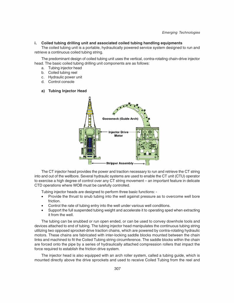
307
Emerging Technologies
i. Coiled tubing drilling unit and associated coiled tubing handling equipmentsThe coiled tubing unit is a portable, hydraulically powered service system designed to run and
retrieve a continuous coiled tubing string.
The predominant design of coiled tubing unit uses the vertical, contra-rotating chain-drive injectorhead. The basic coiled tubing drilling unit components are as follows:
a. Tubing injector headb. Coiled tubing reelc. Hydraulic power unitd. Control console
a) Tubing Injector Head
The CT injector head provides the power and traction necessary to run and retrieve the CT stringinto and out of the wellbore. Several hydraulic systems are used to enable the CT unit (CTU) operatorto exercise a high degree of control over any CT string movement – an important feature in delicateCTD operations where WOB must be carefully controlled.
Tubing injector heads are designed to perform three basic functions: -• Provide the thrust to snub tubing into the well against pressure as to overcome well bore
friction.• Control the rate of tubing entry into the well under various well conditions.• Support the full suspended tubing weight and accelerate it to operating sped when extracting
it from the well.
The tubing can be snubbed or run open ended, or can be used to convey downhole tools anddevices attached to end of tubing. The tubing injector head manipulates the continuous tubing stringutilizing two opposed sprocket-drive traction chains, which are powered by contra-rotating hydraulicmotors. These chains are fabricated with inter-locking saddle blocks mounted between the chainlinks and machined to fit the Coiled Tubing string circumference. The saddle blocks within the chainare forced onto the pipe by a series of hydraulically attached compression rollers that impact theforce required to establish the friction drive system.
The injector head is also equipped with an arch roller system, called a tubing guide, which ismounted directly above the drive sprockets and used to receive Coiled Tubing from the reel and

308
Drilling Operation Practices Manual
guide it into the chain blocks. At the injector head base, a hydraulically- operated stuffing box ispositioned along the coiled tubing centerline and is secured in the chain drive assembly. The stuffingbox or “stripper rubber” contains a split elastomer element that is compressed against the tubing.This isolates annular well bore pressure from the atmosphere. The minimum stuffing box workingpressure rating is 5000 psig, but it is generally designed for working success upto 10,000 psig.The injector head is supported above the well head in one of the two ways. Either telescopic legsor a hydraulically elevated steel frame commonly called a “jack stand” are used.
b. Coiled Tubing ReelIt consists of a fabricated steel spool drum with a core diameter of 60"-72" and a 9’ flange
diameter side. The basic spool can store up to 26,000 feet of 1.00" OD tubing or 22,000 feet of1.25" OD tubing. Tubing spooling capacity is dependent on the core diameter.
The innermost tubing end is connected through the hollow end of the reel shaft to a high pressure-rotating joint. The rotating joint is secured to a stationary piping section connected to fluid pumpingsystem to circulate fluid. One 10,000 psig shut-off valve is provided between the tubing and reelshaft to isolate the tubing from the surface pump lines. The reel rotation is controlled by a hydraulicmotor that is used for constant, steady pull and making sure that the coil is being tightly spooledonto the drum. Motor is mounted for direct drive on the reel shaft or operated by a chain-sprocketdrive assembly.
During lowering of the tubing, slight back-pressure is always maintained on the reel motor toallow the injector head to pull the tubing off the reel and keep tension between the injector and thereel. On the other hand, tubing retrieval pressure increases on the reel motor allowing reel rotationto keep up with the tubing extraction rate out of the well.
The primary function of the reel brake is to stop drum rotation if the tubing accidentally partsbetween the reel and the injector head. The braking system is not intended to halt uncontrolled tubingdispensing but only to offer resistance and slow down reel motion. New reel units have a back-pressuredevice braking system to slow the reel and also a friction pad braking system for extra control. Thefriction pad is applied hydraulically to the outer reel flange diameter to slow reel motion.
c. Hydraulic Power Drive UnitsHydraulic Power Drive Units are sized to operate all of the coiled tubing unit components. The
prime mover assembly size will depend on hydraulic-drive unit needs. The prime mover for a specificcoiled tubing unit may range from a power take-off assembly (Bobtail land unit design) to a self-contained offshore skid package. Standard prime movers packages on most coiled tubing units areequipped with diesel engines and hydraulic pumps.
d. Control ConsoleNormally all controls are positioned on one remote console. It may be skid-mounted for offshore
use or permanently mounted on land units. The console includes all of the controls and gaugesrequired to operate and monitor the coiled tubing drilling unit components. Reel and injector headmotors are activated from the control panel through valves that determine the tubing motion directionand operating speed. Control systems to regulate the drive chain, stripper rubber and blow outpreventor stacks are also located on the control console.
ii. Well control system/ Blow Out Preventer StacksCoiled tubing drilling requires two sets of different blow out preventer stacks assemblies:
309
Emerging Technologies
a. For Bottom Hole Assembliesb. For coiled tubing
a) Bottom Hole Assemblies Blow Out Preventer StacksThis consists of annular preventer, blind rams, pipe rams suitable for bottom hole assemblies
and drilling spool with isolation valves. The return line is used to circulate out the kick or for takingreturns out in drilling an under balanced well.
b) Coiled Tubing Blow Out Preventer StacksThe BOP system is a critical part of coiled tubing drilling units. It is composed of four
hydraulically-operated rams, generally rated for a minimum working pressure of 10,000 psig. Thefour BOP compartments are equipped from top down with Blind Rams, Tubing Shear rams, SlipRams and Pipe Rams.
• Blind RamsBlind rams are used to seal the well at the surface when well control is lost. Blind rams seal
when elastomer elements are compressed against each other.
• Tubing Shear RamsTubing Shear rams are used to mechanically break the coiled tubing in the event coiled tubing
becomes stuck or when it is necessary to cut the tubing and remove surface equipments from thewell. As shear plates close on the tube, mechanical forces yield the tube body to failure.
• Slip RamsSlip Rams are equipped with uni-directional teeth that move against the tubing when activated
to support the pipe weight. In addition, slip rams can be used to secure the pipe by closing on thetube to prevent the movement in the case of high pressure that may blow the tubing out of the well.Slip Rams are fitted with guide sleeves that properly center the tubing in the ram body‘s groovedrecess as slips are closed.
• Pipe Rams or Stripping RamsPipe Rams or Stripping Rams are fitted with preformed elastomer seals that fit the specific OD
of the tubing in use. When closed against the tubing, they isolate well bore annulus pressure belowthe rams. These rams are also outfitted with guide sleeves to center the tubing as the rams areclosed.
iii. Circulating Fluid and SystemThe bore of coiled tubing drilling equipments is very less as compared to conventional drilling
and it results in high frictional pressure losses. Drilling fluid design must give due consideration tothe following three points:
• Minimizing the frictional pressure losses• Producing more HHP to run the mud motors• Have sufficient density to maintain bore hole pressure and ability to sweep hole clean of
cuttings.
Low solids mud system is better suited for this. Coiled tubing drilling circulating system is identicalto conventional drilling circulation system. It also requires mud tanks, shale shakers, desanders,desilters and centrifuges. But the mud system capacity requirement is less in comparison as smallersizes of holes are drilled. Typical pressure and capacity requirements for circulation are in the rangeof 4,000-5,000 psi and 170 gpm. Triplex Pumps (500 HHP) are suitable to meet this requirement.

310
Drilling Operation Practices Manual
iv. Downhole ToolsCoiled tubing drilling gained momentum and acceptance with the innovative work done on
downhole tools and bottom hole assemblies to meet the needs of deepening, re-entries and horizontalwells. Coiled tubing drilling downhole tools are as follows:
a. Drill bitsb. Positive displacement motors (PDM)c. Drill collarsd. Coiled tubing adapterse. Disconnect toolsf. Orienting tools
Drill bits, PDM motors, drill collars and survey tools are borrowed from conventional drillingoperations. Coiled tubing adapters, disconnect tools and orienting tools are unique to coiled tubingdrilling. These specialized tools have been designed of necessity.
a. Drill BitsBits used for coiled tubing drilling should be able to attain adequate penetration rates with
relatively less weight on bit and high rotational speeds. For directional applications, bits with lowtorque requirements should be selected to minimize the complications of reactive torque whilemaintaining the desired well trajectory.
b. Positive Displacement MotorsPositive Displacement Motors are used to turn the bit. PDM are available for coiled tubing drilling
in diameters ranging from 2.375" to 6.5" OD as follows:• High-speed, low torque• Medium speed, medium torque• Low speed, high-torque
Motors should be matched to the bits they will be used with. High-speed, low torque motorsare suitable for those with TSD or natural diamond bits. Medium speed, medium torque motors aresuitable for PDC bits.
c. Drill CollarsDrill collars provide sufficient weight to the bit to achieve acceptable rates of penetration and
also provide adequate strength to enable the BHA to be run in compression. When MWD or steeringtools are used, non-magnetic drill collars are used to prevent magnetic interference with thesedevices. Drill collars should have large enough ID to allow the insertion of the steering tools or MWDsystem and minimize the pressure drop through the drill collar string adjacent to the survey tool.Non-standard size drill collars may be used.
d. Coiled Tubing AdapterCoiled tubing adapter is required to connect the coiled tubing to the BHA. It must be able to
resist the torque developed by the mud motor. Mud motors in the sizes suitable for coiled tubingdrilling can develop torque in excess of 1,000 ft-lbs in a stall situation.
e. Disconnect ToolDisconnect Tool provides a means of disconnecting the coiled tubing from the bottom hole
assembly in case the bit or drill collars become stuck. Disconnect mechanisms are of two types-pressure release or shear release. Disconnect tools have to resist the torque developed by the mud

311
Emerging Technologies
motors. Pressure release disconnects are actuated by pumping a soft ball through the coiled tubing.Shear release tools are actuated by pulling on the coiled tubing until sufficient tension is applied toshear out pins holding the tool together and disconnect the BHA from the coiled tubing.
After the coiled tubing is released, fishing tools can be run to recover the BHA. If the electricline is used, the disconnect mechanism must be designed to accommodate the wire line withoutinterfering with the releasing operation of the tool.
f. Orienting ToolsA downhole rotator or orienting tool is required to alter the tool face orientation to control the
direction of the hole in directional and horizontal drilling. Orientation tools are actuated by mechanicalreciprocation, pressure cycling, torque from the drilling motor, downhole electric motors or acombination of these actions. The tool is run above the mule shoe sub in the BHA. Orientationtools either allow for continuous adjustment or tool face orientation over a fixed range of rotation orfor indexed tool face rotation with no limit on the total range of adjustment available.
CTD Applications
New WellsCTD units can handle small and shallow new wells, typically 1500-1800 metres deep, with hole
diameters up to 8 ½”. In some softer operations the hole size may reach 12-1/4" however, the casingsize will be limited to a final production casing of 3-1/2". Recent technical advances continue topush these limits. CTD is effective for new shallow gas relief wells being drilled in Indonesia andVenezuela. The small amount of equipment placed to risk, as well as the advantages of personalsafety, supports the use of CTD.
Many of today’s new well projects, however, are not especially suited to CTD, mainly becauseof current market economics. In many regions of the world, the relatively new CTD unit and its bulkof required ancillary equipment must compete against a depreciated drilling rig. In these areas,the CTD unit is not an economic alternative to the conventional rig. CTD however providesenvironmental advantages like small footprint, reduced environmental impact, location remotenessand limited space on offshore platforms.
Conventional Re-entryDeepening and sidetracking wells cover the bulk of the conventional re-entry market, and CTD
is suited to a portion of these operations. For sidetracks, a whipstock is set at the kick-off depth,and a window is milled in the casing. In such types of wells CTD has limitations of maximum holesize (6") and build up rates (>30 degree/100 ft). For horizontal sidetracks the drain hole length islimited by the required WOB. Here too CTD units have to compete with depreciated drilling rigswith low day rate. Here too CTD has the same environmental advantages as for new wells. CTD isalso useful for offshore where UBD is required due to depleted reservoir pressures.
Through-tubing Re-entryOther than UBD applications of CTD, the most technically and economically successful
applications of CT are in through-tubing reentries. Through-tubing reentries are typically drilled todeepen or sidetrack a well and are performed without removing the well’s production tubing. Theseprojects are suited to CT because no additional equipment is needed to pull the tubing. CTU canmove in, rig up, and begin drilling within hours. This quick rig up is especially attractive in offshoreand artic locations, where drilling and workover rigs have higher day rates. Here too there are limitations

312
Drilling Operation Practices Manual
in production tubing and hole sizes. For directional drilling, the bottom hole tools limit the applications.Combined with UBD, through-tubing reentry drilling projects provide for the highest potential costsavings for the operator.
Underbalanced Drilling (UBD)In true UBD, the well flows while the hole is drilled. The well is not killed while pipe is tripped.
This underbalanced condition prevents drilling fluid from entering and damaging the producingformation. This drilling technique is possible with jointed pipe, such as with snubbing units, but ithas proven safer and more efficient with CT where the sealing is provided in the injector.
Underbalance drilling can be applied in combination with any other application (shallow wells,conventional or through-tubing reentries). The only limitations are those associated with one of thesethree applications.
Sidetracking Technology for Coiled Tubing Drilling.CTD has been used increasingly in recent years for extending existing wells (re-entries and
multi-laterals). Through-tubing drilling is a major application for CT drilling. The motivation drivingthrough-tubing drilling is low cost rigless re-entry when overbalanced and safe drilling with Christmastree and tubing in place when under balanced (for reduced formation damage). In addition the caseof drilling 4-3/4" and smaller boreholes with the CT is an advantage in a region that does not havean established practice of slim hole drilling.
The key enabling technology for viable through-tubing drilling is the ability to sidetrack in casingbelow the tubing tail. With the advent of CT drilling, the option of through-tubing drilling has becomea reality and the following through-tubing sidetracking techniques are available for circumventing aproduction problem.
a. Cementing sidetracking (CS)b. Whipstock in cement (WIC)c. Through-tubing whipstock (TTW)
a. Cement Sidetracking (CS)This technique is the most straight forward. It consists of placing a specially designed cement
plug in the casing and drilling with a bent housing motor to cut the window and lateral. The advantagesof this technique include that no iron is left in the well (the cement can easily be drilled out ifnecessary at a later date) and there are few opportunities for something mechanical to malfunction.If the existing wellbore must be plugged and abandoned, the cement kickoff plug may be effectivelyfree, making this the most economical technique. The disadvantages of this technique are the shortwindows, technique sensitivity, and the relatively fragile cement ramp. Because the whipstock iscement, all subsequent operations through the window must be made carefully and preferably withoutrotation. This technique has been successfully used for 3-¾” and 4-½” hole sidetracks in both 7"and 9-5/8" casing at deviations from 110 to 900.
Two techniques have been used to initiate cement sidetracks. If the pilot hole and the exit areon the same side of the casing, the technique is referred to as a CSS (cement sidetrack sameside). If the pilot hole is on one side of the casing and the BHA is then oriented to drill toward theopposite side of the casing, the technique is called CSO (cement sidetrack opposite sides). TheCSS technique has the advantage of direct application of full BHA elastic load at a known depth.The CSO technique has the advantage that the mill hits the casing with an angle of attack, andhence is required to cut less casing (for the same dogleg severity), and also the cement is muchthicker at the top of the window.

313
Emerging Technologies
b. Whipstock in Cement (WIC)This technique is slightly more complicated than the CS technique. The casing is filled with
cement (preferably to the tailpipe) and a through-tubing directional assembly is used to drill a holeto the inside of the casing at the proper tool face angle. Enough straight hole is drilled adjacent tothe casing to make a straight rathole for the whipstock. The procedure described above can beused if the well is theoretically deviated more than 30 at the point where the whipstock is to be set.From a practical stand point, a hole deviation of more than 100 may be required for stable tool facereadings while drilling (this applies to the CS technique also). A bottom trip whipstock is run in witha bottom hole assembly (BHA) of;
a. whipstockb. starter millc. steering toold. CT
c. Through-Tubing whipstock TTW).Several versions of through-tubing whipstock exist. All consist of an anchor that reacts torsional
and axial loads and are designed to allow the small through-tubing diameter to span from the highside to the low side of the much larger casing inside diameter. All TTW are normally used for anear high side exit. This is to allow gravity to force the upper whipstock taper to lay against the lowside of the casing.
Coil Tubing Under balanced Drilling – Challenges
• RigsIn the early 1990’s when directional Coiled Tubing Under balanced Drilling first entered the market,
conventional Coiled Tubing units were utilized with modified substructures and cranes supportingthe injector over the well head. The main draw back to these units was the size and length of coilthey could facilitate. As the benefits and rewards of Coiled Tubing Under balanced Drilling grew, sodid the Coiled Tubing drilling rigs.
• ToolsCoiled Tubing Under balanced Drilling tools have always offered a challenge to provide reliable,
trouble free operation but this can usually be attributed to their small size and extreme conditionsthat they are exposed to while drilling under balanced. Major improvement to bottom hole assembly(BHA) and motor design has generated tools that rarely malfunction in their basic componentry.Additional instrumentation such as internal /external pressure and temperature, weight on bit (WOB)Measurement, gama ray and resistivity readouts have been introduced to the BHA through real timesignals that only CTUD can supply. Motor life is a key issue with Coiled Tubing Under balancedDrilling. Due to the inability to rotate the tubing in the hole, drilling of the formation relies on bitrotation alone. When high volumes of gas are pumped through these motors the gas impregnatesand swells the stator rubber, decreasing the torque out put to the bit and resulting in excessivemotor trips.
• CoilCoil manufacturers have been able to meet the demands of the industry to develop tubing
specifically designed for drilling. The typical diameters are concentrated around 60.3 mm and 73.0mm. Some contractors have opted to utilize pipe size like 66.7 mm, 82.6 mm and 88.9 mm inorder to gain minimum bulking/reduced annular space advantage. With larger Coiled Tubing Drillingrigs for Under balanced drilling available in the market, coil wall thickness has increased dramaticallyalong with yield strengths to try and extract as much fatigue life as possible out of each string of

314
Drilling Operation Practices Manual
tubing. Jointed drill pipe is available in various diameters and weights and has a distinct advantageover coil by replacing any section of the string when required. Butt-welding of the coil throughexperience, technique and material, has seen vast improvements but still creates a high fatiguearea in the drill string.
• Standby TimeOne of the largest contributors to high Coiled Tubing Under balanced Drilling prices is “stand
by time”, especially when daily costs of a multitude of services are already quite high, Coiled TubingUnder balanced Drilling can usually be split up into three main services: -
• Coiled Tubing and pumping• Production testing equipment• Directional services
This separation can prove to be costly. If one of the services has problems the rest continue tokeep charging.
• EngineeringOne of the most critical aspects involved with Coiled Tubing Under balanced Drilling operations
is the preplanning of the job by all parties involved. Drag and buckling analysis, circulation analysis,hole sizing depths fluids and BOP are typically referred to by Coil Company. Well bore trajectoryreservoir lithology, tool sizing, and boundary restrictions are planned by directional services. Reservoirfluids/gasses, pressures and flow rates are analyzed by the production testing company.
Contingency plans are always necessary while drilling under balanced with Coiled Tubing.
• Integration of Coiled Tubing Under Balanced DrillingIf Coiled Tubing Under Balanced Drilling is thought to be advantageous, the equipment and tools
have been proven and the well bore configuration is conducive to utilizing coil, then the final steptowards creating an economically effective operations is to integrate the services involved. Bycombining all related services into one, rather than incorporating the necessary services availablethrough one company, the experiences level will increase, risk will decrease and cost will bepredictable.
Since Coiled Tubing has typically been implemented as a live well intervention tool, this technologyhas always been linked with under balanced drilling.
Proper candidate selection and job planning is critical to the success of under balanced drillingjobs. There are numerous issues to consider when contemplating an under balanced drilling project.Many of these issues are common to both jointed pipe and joint less pipe (i.e. Coiled Tubing) drillingoperations.
One of the major issues associated with under balanced drilling is that of borehole stability.Many of the growing number of candidates for under balanced drilling exist in depleted, or underpressured reservoirs where under balanced drilling serves to alleviate many of the drilling problemsassociated with overbalanced drilling. These include massive losses of circulation and differentialsticking.
• Rate of PenetrationOptimizing rate of penetration with Coiled Tubing must be achieved with limited weight on bit. It
is important to keep in mind that Coiled Tubing is plastically stressed and due to absence ofconnection, it can safely be used in compression. By comparison, jointed pipe operations utilize

315
Emerging Technologies
drill collars further down in the string (usually near the bottom of the vertical section) to provideweight and maintain the drill pipe in tension. The weight of the Coiled Tubing or combination of theCoiled Tubing weight with injector force wills more than make up for the lack of drill collars. However,due to the helical nature of Coiled Tubing and the inability to rotate friction is increased resulting inthe reduction of the effective transfer of weight to bit. The available weight on bit also does notincrease with increased depth. The additional weight of Coiled Tubing due to increasing depth istaken up in friction due to helical buckling in the vertical well bore. Typically, rate of penetrationwith Coiled Tubing is controlled by motor/bit selection and the reduction of hydrostatic pressure onthe formation (i.e. under balanced drilling)
• Hole CleaningOptimizing hole cleaning parameters with Coiled Tubing and multi-phase flow is not a well
understood science especially in highly deviated or horizontal wells. In general, it is felt that foamis superior to nitrified fluid (more susceptible to slugging) for cuttings removal. As a general rule ofthumbs foam qualities around 80% are preferred to minimize cuttings beds in the horizontal wellbore and build section. By comparison experience with non-foamed multi-phase flow has experiencedsuccess with qualities around 60% or less. Where effective hole cleaning can be achieved withnon-foamed or nitrified fluids, this system is usually simpler to manage. Foam, typically has higherfriction and this can limit the ability to reduce bottom hole pressure, however good, stable foam willbe more homogeneous and make cuttings transport more predictable.
• Bottom Hole PressureBottom hole pressure is a function of nitrogen to liquid ratio in either case; reduction in bottom
hole pressure below reservoir pressure can sometimes stimulate influx of reservoir fluids. This influxwill affect the bottom hole pressure depending upon the nature of the influx (gas, oil or water) andthe rate of influx. Liquid in flux will tend to be self-regulating in under pressure formations while gasinflux can often result in significant unloading of the well bore.
• CostCost, of course, is the driving parameter behind most oilfield operations. However, it is more
prudent to consider value than to focus strictly on costs of individual items in a reservoir managementscheme. For example while increasing nitrogen rates may result in higher nitrogen cost per unittime, resultant increased penetration rates or improved hole cleaning leads to reduced risk of stuckpipe and reduced wiper trips.
Coiled Tubing Horizontal DrillingCoiled tubing drilling for horizontal wells requires the following special purpose tools:1. A downhole surveying tool2. Bent sub3. An adjustable bent housing on PDM.4. A downhole orientating sub-assembly which allows proper tool face orientation during
directional drilling.
Research and developments which have specifically led to the coil being successful for horizontaldrilling are:-
a. Thrusters which allow higher weight to be placed on the bit in the horizontal section.b. Torque reactors which compensate for the reactive torque from the drilling process.c. Rotators which give one option of rotating the BHA to overcome drag friction which has
limited the length of horizontal wells achievable with cost.
316
Drilling Operation Practices Manual
Coiled Tubing LifeFailure of coil tubing is mainly due to the repeated bending and plastic deformation of coil tubing
on and off the reel and gooseneck during Coiled Tubing drilling operations.
CT Failure CausesStatistical analysis of CT failure causes are as follows:1. Corrosion 51%2. Overload 21%3. Mechanical damage 12%4. Manufacturing defects 07%
Though the mechanism for predicting Coiled Tubing life is not fully understood, still it has beenpossible to predict very closely actual life performance. Coiled tube working life is affected by CoiledTubing size and thickness, internal pressure, yield strength, reel diameter, gooseneck radius,operating conditions (corrosion etc.). Based on scientific studies carried out, it shows that CoiledTubing life can be greatly increased by increasing Coiled Tubing wall thickness and Coiled Tubingstrength, while the Coiled Tubing working life decreases under high internal pressure, corrosion,butt weld conditions etc. It can be seen that;
1. CT life increases with smaller OD of CT2. CT life increases with higher wall thickness3. CT life increases with higher yield strength.4. CT life increases with increase in reel diameter and gooseneck radius.5. CT life reduces with increase in internal pressure.6. CT life reduces with corrosion and after operating conditions.
CT MetallurgyPrecision Tube Technology, Quality Tubing Incorporation and South Western Pipe Inc. are the
major manufacturers of these coils. The steel used for making coils is mainly High Strength LowAlloy Steel (HSLA). A typical steel composition of A606 alloy type 4 modified is as follows:
CompositionCarbon 0.1-0.15Manganese-0.6-0.9Phosphorus-0.030 max.Sulphur- 0.005 maxSilicone 0.3-0.5Chromium-0.55-0.70Copper-0.2-0.4Nickel-0.25 max
Physical PropertiesMinimum yield strength 70 ksiMinimum tensile strength 80 ksiMinimum Elongation 30 %Maximum Hardness 22C Rockwell
Capabilities (Advantages) Of CTDa) Fast trips
A primary consideration of CTD is that the pipe is continuous, and does not require the make-up of connections during operations. This feature allows for faster handling and tripping speeds thatcan contribute to reduced costs.

317
Emerging Technologies
b) Drill and trip underbalanceCoiled tubing systems have been designed to operate under live-well conditions and have a
commendable safety record in performing this type of work. Traditional drilling practices includeusing the drilling fluid as a pressure control system (first line of defense). Coiled tubing systems,alternatively, have first and second lines of defense in their stripper rubbers and BOP systems thatrender the need to have weighted drilling fluids redundant. Both drilling and tripping can occur whilethe well is under pressure.
c) Small footprintThe coiled tubing drilling unit is significantly smaller than a conventional drilling unit requiring
less wellsite preparation and is very suitable for urban areas, remote offshore/land locations andother locations where land availability and environmental impact is of great importance.
d) Direct control and MonitoringThe continuity of coiled tubing merits use of electric wire line in the tubing that facilitates
continuous, high quality two-way telemetry between surface and downhole for real time data andcontrol.
e) Considerable safety advantages• Closed system permits continuous well control even when tripping.• Quicker shut-in in emergency situation.• Easier to handle a kick.• Wellbore isolated from atmosphere any time that is desirable.• No personnel needed near the wellhead during most operations, including trips.
f) Reduced environmental impactCTD operations generate less noise and fewer emissions. Smaller diameter wells generate smaller
volumes of cuttings.
g) PortabilityAs coiled tubing drilling does not require a mast, rotary table etc., the equipment required for
CTD is much smaller than for a conventional rig. Hence mobilization, rig up and rig down are faster.
h) Continuous circulationThe circulation system in CTD operations is so complete such that circulation can continue
even while the trip is taking place.
i) Slim hole capabilitiesWith larger diameters coiled tubing now available, coiled tubing can be used to drill or core
slim holes. Further the operator can opt to complete the well with coiled tubing in place, thuseliminating the casing. Slim hole technology can further be applied to;
• Vertical deepening• Small cased, wellbore re-entries• Short radius re-entries.• Horizontal drilling with coiled tubing.
Limitations Of CTDa) Annular Velocity for cuttings removal
Sufficient annular velocity is required for removal of drilled cuttings. However, it is limited bythree factors:
• Coiled tubing pressure losses.

318
Drilling Operation Practices Manual
• Flow rate for downhole motor.• Flow rate for MWD.
b) Downhole weight on Bit (DWOB)WOB is critical at the end of the build section and at TD. The bending friction force in the
curved section affects the DWOB and consequently the maximum reach. Coiled tubing OD andwall thickness have significant effect on reach. WOB of 100 lbs per square inch of bit diameter isrequired to achieve practical ROP. Helical buckling of coiled tubing in the 9 5/8" casing will increasethe friction forces and thus reduce the weight that can be applied on the bit. If coiled tubing is runinside 7" casing or smaller, relatively more DOWB can be supplied to the bit.
c) High Circulating PressuresFriction losses in the coiled tubing results in higher circulating Pressure and tend to limit the
flow rate and hence effects the selection of mud motor. Well-designed drilling fluid properties shouldhelp in decreasing friction losses without sacrificing carrying capacity.
d) TensionThe maximum allowable tension depends on the pipe OD, ID and the fluid strength of the pipe.
e) TorqueThe maximum stall torque of the drilling motor will impact the selection of coiled tubing pipe.
The stall torque depends on the flow rate th rough the motor. If the pump rate is reduced, the stalltorque is also reduced.
f) Short Coiled tubing LifeOne to two wells can be drilled with the same reel, depending on the drilling depth and problems
encountered while drilling. Number of cycles over the gooseneck, in addition to depth and pressureshould be closely monitored to determine if the CT reel can drill a second well. Heavy wall pipe andhigh yield strength improve the CT life.
g) Weight and size limits.In order to do larger jobs, it may be required to take multi reels to location, weld or connect the
coiled tubing on site and spool it on a larger work reel. However, the cost will be considerably high.
h) Limited ReachThe amount of the reservoir drained is generally a function of the length of the horizontal section.
The reach of the coiled tubing is limited by the limitations in the amount of weight transmitted tothe bit.
i) No rotation from surfaceThe inability to rotate the coiled tubing from the surface makes directional drilling more difficult,
increase the possibility of sticking, inhibits cutting removal and increases pipe drag. Frequent wipertrips are required to compensate for this absence of pipe rotation.
j) Limited fishing capabilitiesDue to the very small clearance especially in slimholes and re-entry drilling, availability of reliable
fishing tools is a major concern.Thus in many cases stuck ups requiring fishing cannot be liquidatedand often results in repeat sidetracking or abandonment.

319
Emerging Technologies
Information Influenced parameter
Hole, casing and tubing sizes Annular velocity, CT Reach/ WOBHole, casing and tubing depths. CT reach/WOB
Motor Size Flow rate, annular velocity
Well trajectory and Total depth CT reach, WOB, Coil Tubing tension
CT Size and wall thickness Flow rate, CT reach/ WOB, CT tension
Injector capacity Depth, CT size
k) High cost of operationsCTD operations for normal wells are costlier than conventional rig operations.
Techno-Economic FeasibilityThere are many factors that go into determining both the technical and economical feasibility
of CTD candidates. Of these factors which influence the economic feasibility, some tend to increasethe competitiveness of CTD while some tend to reduce it relative to other possible solutions. Theseeconomic parameters include; the number of wells to be taken up, production benefits from drillingunderbalance and possible reduced cost of through-tubing operations.
Technical feasibilityWhile advances in CT services have tremendously increased its usage, limitations still exist.
This is especially true for drilling projects, where the CT equipment is very small when comparedwith a conventional drilling rig. A thorough review is required to ensure that the CT is capable ofperforming the tasks that are required of it to drill. To optimize drilling, the operator must optimizethe rate of penetration, trip time and hole cleaning. However, the size of the pipe introduces a numberof constraints on the operator when drilling with CT.
To achieve the best rate of penetration, the operator must optimize the hydraulic and mechanicalpower at the bit. Yet, the small CT limits the flow rate that can be achieved through the pipe. Thedepth of the hole is also limited by the tension that can be put on the CT while the diameter islimited by the annular velocities that can be achieved outside the CT.
Therefore, to determine the technical feasibility of any CT drilling project, each of these itemsmust be evaluated.
The following table elaborates the above;
Coil Tubing drilling has limitations, depending on the desired application in drilling. Consideringthe limitations, coil tubing drilling is specially suited for certain applications.
Economical FeasibilityGenerally, the economic feasibility of a coiled tubing drilling job depends on the location and
scope of the project. Evaluating Coil Tubing differs a bit from evaluating a conventional drilling job.With a conventional rotary rig; the required equipment typically arrives on location with the drillingrig. These rigs are built to be mobilized and demobilized many times.
In contrast, with a Coil Tubing drilling unit, ancillary equipment is not typically part of the basicrig package and must be rented separately. The pipe, injector head, power pack (for CTU only),Coil Tubing blow out prevents (BOPs) and control cabin can be expected with the Coil Tubing unit.

320
Drilling Operation Practices Manual
The mud equipment, fuel tanks and pump, generator, electrical equipment, and accommodationsare some of the additional surface equipment that may be required.
If a job requires pulling or running a jointed completion, a jack-up frame and power tongs will beneeded, in addition to the normal completion hardware. Conventional drilling equipment will be requiredfor the bottom hole assembly. For vertical holes, this equipment should minimally include bits, drillcollars, mud motor and drilling jars. For deviated /sidetrack holes, other equipment, such as steeringand orientation tools, monel drill collars, whipstock, casing collar locator, cement bond tools andmills for window milling, may be required. Acquiring all this additional equipment can be costly andtime consuming. For this reason alone, some Coil Tubing drilling jobs may not be feasible andmultiwell projects may be required to justify the cost associated with the mobilizing this equipment.
The future of Coil Tubing drilling as a commercially viable alternative in the coming days willdepend on developments such as the price of oil and the rig day rate charges and other developmentssuch as Coil Tubing drilling specific technology. Some areas for improvement, which will directlyimpact the economic viability of Coil Tubing drilling, are:
Shorter more flexible BHA, which will allow higher build rates.More reliable and sensitive orienting tool which will allow wells to be steered with moreprecision and faster.More sensors including for WOB, resistivity etc.Better understanding of Under Balanced drilling (UBD) which will allow us to better optimizepotential benefits of UBD for different reservoirs.Improved casing exiting techniques will allow wells to be drilled more economically and ina more wide variety of conditions (casing size, inclination).Hybrid Coil Tubing drilling equipment will bring more versatility and efficiency by allowingoperations such as running jointed tubulars in addition to drilling in a single unit.
ConclusionsUnless there are specific advantages to be gained from using coiled tubing it is difficult to be
commercially competitive. The are however, specific types of drilling operations in which Coil Tubinghas a technical advantage and in these situations the economic case is much more easy to justify.
The areas in which there are distinct advantages to using coil tubing are:Through-tubing drilling where the cost of pulling the completion string can be avoided andre-entry is done through the existing completion tubing.Coil Tubing is a safer and more reliable way of drilling wells in an underbalance state withnumerous production benefits.For pilot or relief wells; Coil Tubing with its pressure seal at surface is ideally suited tothese types of wells which are difficult to control by the drilling fluid alone and thus tend tobe quite dangerous.Offshore platforms or remote locations where the cost of rig is often prohibitive.Location of candidate wells – whether the well is drilled in a remote location or an urbanarea, offshore or on land, the amount of site preparation needed etc, will have an impact onthe commercial viability of Coil Tubing drilling. In areas with environmental requirements,Coil Tubing drilling is often advantageous because fewer rig loads are required and resultinglocation is smaller than that of a conventional drilling rig. In jungles, mountainous regions,national parks, and urban areas, a small wellsite footprint is desirable to reduce environmentimpact. In offshore the smaller location need of Coil Tubing drilling unit becomes especiallyattractive because many platforms have limited deck space.

321
Emerging Technologies
IV. Slant Drilling
One of the major factors in the analysis of the economic viability of Coil Tubing drilling isthe number of wells to be done in a campaign. There are significant start up costs associatedwith this service. Increasing the number of wells to be drilled or going to continuous operationswould reduce these costs. Continuity of personnel and hence improved efficiency throughexperience, reduced mobilization costs etc. can be realized in continuous operations.
Slant Drilling is the technique of drilling from a slant angle at the surface (45° max. in 1.5°increments), and zeroing in on shallow-depth targets. Slant drilling is an ideal option for reachingtarget zones that are relatively shallow and may sometimes be necessary to negotiate difficult terrainconditions, such as drilling under bodies of water, population centers or environmentally protectedareas.
A conventionally drilled directional well is typically started with a vertical section from surface.Specially designed bottom hole assemblies or mud motors are then used to deviate the well at anappropriate angle to reach the target. In contrast, slant hole drilling attains the shortest drillingdistance by allowing the well to be spudded at an angle aimed directly at the target. With the properdrilling rig, the well can be drilled straight to the target. The slant hole path can be deviated additionallywith the use of conventions directional tools, including into a horizontal direction.
The major applications for this technology have occurred in the shallow depth, heavy oil areas.The multi-well pad approach of slant technology is conducive to the drilling of the numerous wellsrequired in these areas. Other applications include wells that require considerable horizontaldisplacement, especially at shallow depths.
Since the 1960fs, the drilling industry has experimented with the concept of automated drillingrigs. In Canada during the 1970’s, small hydraulic rigs were developed for shallow drilling. Theserigs featured hydraulic power swivels and partially automated pipe-handling systems that improved

322
Drilling Operation Practices Manual
both drilling performance and rig move times. An offshoot of this technology was the developmentof the first slant-drilling rigs which could spud from vertical to 45°.
The 1990s saw the revival of slant technology, which was used most successfully in heavy-oildrilling at shallow depths. This differed from directional drilling in several ways:
• It followed a shorter, more direct route. Wells could be spudded at an angle—usually30[degrees] to 45[degrees]—and then aimed straight at the target.
• It was less expensive, faster and more productive than directional horizontal drilling.• Slant drilling allowed shallow heavy-oil deposits to be developed from one or several pad
locations, which vary in number of wells. Pad drilling also emerged as a way to minimizeenvironmental impact because it allows multiple-well access to larger areas and targetsbeneath sensitive areas, such as lakes and towns.
Precision DrillingPrecision Drilling, Canada is the worldwide leader in slant rig technology. Precision Drilling, a
division of Precision Drilling Ltd., is Canada’s leading drilling contractor with a well maintained fleetof more than 229 rigs including singles, doubles, light triples, heavy triples, coiled tubing rigs, asurface hole rig along with the skilled personnel to drill at any depth. Their fleet consists of 15singles, 95 doubles, 45 light triples, 41 heavy triples, 11 coiled tubing rigs, 16 singles and 21 SuperSingles.
The Super Single rig is ideal for drilling multiple wells from a single location (pad drilling) includingdrilling in environmentally sensitive areas. For well drilling up to 3000 metres in depth, PrecisionDrilling manufactures and operates Super Single rigs which feature top drive units, longer range IIIdrill pipe, and automated pipe handling capabilities.
These rigs are capable of slant drilling, which is done by tilting the rig mast from vertical. Slantdrilling is used to drill several wells from one location, saving the time and avoiding the environmental

323
Emerging Technologies
impact associated with setting up a rig in a number of different locations. Slant drilling is also beingused by Precision Drilling with increasing frequency in support of the steam-assisted gravity drainagemethod of recovering bitumen from oil sands.
Precision’s Super Single rig, developed in the early 1990s, has evolved over several generationsto offer such benefits as fast and simple movement between sites, remote control features thatminimize manual labour, control processes that alleviate safety concerns, and the ability to drill anumber of different kinds of wells.
Once merely identified as a slant drilling rig, the Super Single rig has evolved to become aknown versatile drilling rig that is competitive in many drilling operations within a 3000m depth rangeand is unmatched by any land rig today. This versatility makes the Super Single rig ideally suitedto shallow land operations throughout the world.
Weatherford International has in September 2005 completed its acquisition of Precision DrillingCorporation’s Energy Services Division and International Contract Drilling Division. Hence nowPrecision Drilling International is a division of Weatherford and is totally independent from PrecisionDrilling Corporation.
A NUMBER OF `SUITCASES’ CARRY POWERAND DRILLING FLUIDS BETWEEN THE TWOCOMPLEXES. LEASE DIMENSIONS DICTATE
THE NUMBER OF SUITCASES REQUIRED.
TYPICAL SUITCASE LENGTH (EA.): 40’ (12m)(PIN-TO-PIN)
STATIONARY CENTRAL COMPLEX
MULTI-WELL PAD CONFIGURATION
`ALL PDI DRILLING UNITS SHOWN IN THE `MULTI-WELL PAD RIG CONFIGURATION’ALSO CAN BE ARRANGED TO ACCOMMODATEA `SINGLE-WELL PAD’.

324
Drilling Operation Practices Manual
A new generation slant rig’s main rating are as below.1. Depth Rating: Up to 9,800’ (3,000m)2. Mast Capacity: Up to 150 tons (133,500 daN)3. Slant Rig Mast Adjustable Vertical To 45º4. Travelling Equipment Guides5. Overall Height: 75’ (23m)6. Hook Load: 125-150 Tons (111,300 -133,500 daN)7. Pull Down: 100,000# (44,500 daN)8. Drill Collars: Up to 8" (203.2 mm) (RII)9. Hole Size: Up to 26" (660 mm)10. Casing: Up to 18 5/8" (473 mm)11. Top Drive Torque: 30,000 ft-lbs12. Top Drive Speed: 150 RPM13. Drill Pipe: Range III – 13Mtrs
Rig-DesignThe initial concept for slant drilling was to develop shallow reserves that could not be reached
economically with conventional direc-tional drilling. Advances in slant-drilling technology andexperi-ence have expanded the slant-drilling role. It now can be considered an economic alternativeto vertical development in many cases. Ex-perience with the latest generation slant rig has shownsufficient improvements in performance to reduce drilling costs below those experienced on equivalentvertical wells. The main factors that have contributed to improved rig performance during the pastdecade include the following.
Tubular HandlingOn most slant rigs, all tubulars are laid down when tripped. This is accomplished with a hydraulic
pipe boom that raises pipe from horizontal to the well bore inclina-tion.
Pipe HandlingThe latest generation of top drives used on slant rigs now have hydraulic elevators; thus, only
one makeup/breakout is required for each joint. In addition, these top drives have makeup/breakoutwrenches allowing connections to be made up/out in the mast as required. The entire pipe-handlingas-sembly on the top drive also can rotate 360°. When running casing, this feature acts as aninfinite-position stabbing board and provides accurate thread alignment. Drill pipe and casing aremade up by the top drive. When ac-curate casing torqueing is required, a power tong can be addedwith minor rig modifications. Using con-cepts adapted from large power casing tongs, a wrenchwas built to spin and torque drillpipe, collars, and casing in a single opera-tion. Torques up to 100000 N-m can be generated with these wrenches.
Top Drive. The initial top drives used on slant rigs were modified power swivels, which were adequatefor the shallow gas wells drilled. The top drives used on the newer slant rigs are 450 kW unitscapable of 20 000 N-m drilling torque and 320 rev/min.
Fluid HandlingOn present pads, sumpless drilling is used. The mud is reused up to 16 times. The advantages
of sumpless drilling include the following.
325
Emerging Technologies
1. Rig placement on the pad is simplified because individual sumps do not have to be workedaround. Only a small remote sump is required.
2. By reusing the drill fluids, cleanups are simplified. This reduces the environmental effectsof the drilling operation significantly.
Fluid TransferIn the latest generation of slant rigs, a small tank is situated at the rig flow line. The following
items are designed into the tank.1. Linear motion shakers at the flow line virtually eliminate solids-generation problems during
fluid transfer.2. All plumbing for the rig’s well control remains fixed. The choke manifold, degasser, and trip
tank are incorporated into this tank. This allows for the same well-control hookup regardlessof well bore inclination.
Remote Tank DesignTo allow for sumpless drilling, the remote mud tank was designed with the following features.1. Adjustable skimmers between tank compartments to allow for either top or bottom
equalization.2. A separate suction manifold between the first two compartments to allow flexibility for the
cen-trifuge suction.3. Agitators on each compartment to improve solids removal and prevent solids loading during
extended pad operations.4. Variable-rate chemical injectors for injecting flocculent directly into centrifuges while clearwater
drilling on top hole. Each injector should be equipped with an agitated mixing tank.
Transfer UmbilicalWith the advent of electric slant rigs, the transfer of fluid and power between the main and
remote rig sys-tems for pad drilling became more complex. Initially, umbilicals on mechanical rigsused cable stands and flexible hose. This sys-tem was adequate but caused freezeup problemsduring winter op-erations. Today’s electric rig umbilicals typically consist of 10-m enclosed sections.The drilling-fluid, water, steam, and BOP hy-draulic lines run in a heated enclosure with the electricallines strung above the transfer cases.
Rig MobilityThe first slant rigs were designed for single-well ap-plications. They were moved in a manner
similar to conventional trailer rigs. As pad drilling progressed, the ability to move the en-tire drillingmodule in a single load was necessary. Pad rigs now are designed with heavy-duty 16-wheeIsuspensions beneath the substructure. Each eight-wheel bogie on the suspension is mounted on aturntable allowing rig movement in any direction. The entire rig can be jacked up on hydraulic ramsallowing the suspension to be positioned as required. The catwalk end of the rig is mounted on asmall skid plate. Once the rig load has been placed on the sus-pension, these rigs are moved withtwo bed trucks by use of winch lines on either end of the rig. Because they are light, the shakertank, water tank, and doghouse are skidded to the next well slot. These rigs are capable of rigrelease to spud times of <5 hours.
SafetyThe development of slant-drilling rigs has resulted in op-erations that are safer than those of
conventional vertical rigs. Sever-al safety benefits can be attributed to slant drilling.

326
Drilling Operation Practices Manual
Pipe HandlingAll pipe handling is performed from remote lo-cations. Rig crews are never in direct contact with
tubulars on the drill floor. Slant rigs are not equipped with catheads or spinning chains. In addition, aderrickman is never required to be in the mast because all pipe is laid down on every trip.
Rig MovesDuring pad drilling, the main power generation, mud system, and mud pumps are never moved
on inter-well moves; thus, rig move accidents that occur during this phase of the-rig move areeliminated. In addition, the main rig module requires very lit-tle rig up or rig out on an inter-wellmove because the entire unit is moved as one piece.
Programmable Logic Control (PLC)Most functions for the latest generation of slant rigs are controlled with a PLC. Because all
these functions are programmed, the ability to program safety interlocks is very easy. The rig crewcannot perform a sequence of steps that may lead to an accident or equipment damage. The PLCsprogram can be updated continually as new safety and equipment concerns are identified.
Running CasingThe entire opera-tion is hands off, including the power tong operation. As a result, accidents
while running casing are virtually eliminated.
Picker CraneSlant rigs do not have V-door ramps. To allow equipment to be transported to the drill floor, a
hydraulic picker is used. Again, the rig crew is removed from directly handling heavy equipment.
Blow Out Preventer (BOP)The BOP is nippled up in a slant mode which aligns with the tubular running path, thus minimizing
the wear and tear. The topmost pipe is in tension and will be rubbing on the wear bushing in thewellhead. The string is further supported by an hydraulic arm below the drill floor which moves thetubular path to minimize contact with BOP.
Remote Control FeaturesFully mechanized, using state-of-the-art technologies to minimize manual labor, the rig’s remote-
control features reduce the crew’s exposure to harsh weather. These features include:Hydraulic tubular handling armHydraulic power wrenches for make-up and break-out of tubularsHydraulic power wrench carrierHydraulic top driveHydraulic BOP handler and hydraulic pulldownPneumatic tubular slipsHydraulic pipe tables for gravity indexing of tubulars and casings to and from the catwalkHydraulic tubular kickers and indexer systems that index tubulars from the catwalkindividually into the tubular handling boom, or kick tubulars out of the handling boom andonto storage racks or tables.
In addition to efficiency gains, this high level of equipment control has the specific benefit ofdrastically reducing connection times. The hydraulic pipe tables lift joints of drill pipe to the catwalk,where the hydraulic pipe arm is located. The indexers then roll the joints onto the catwalk and into

327
Emerging Technologies
the pipe arm, which lifts the joints individually to the derrick. A top drive screws directly into eachjoint, eliminating the need for an awkward and heavy kelly. The entire connection process takesless than a minute, a fraction of the usual three to five minutes required by conventional single anddouble rigs.
The BOP Handler accommodates a 540mm annular BOP
Personnel are required to operate the controls, run the equipment, perform basic maintenance,disassemble the rig and rig up at the next drill site. The chief difference is that the equipment doesmost of the work, eliminating the labor-intensive and dangerous component of tubular handling. Thisnot only makes the entire process more efficient, but also improves safety considerably.
Safety Benefits
Special consideration to areas of exposure of personnel to hazardous operations is given duringthe application and control of the equipment throughout the drilling rig. Being a single style of rigand using equipment to lay down and pickup pipe in all tripping operations, the Super Single rigdoes not require personnel to be in the mast for anything besides servicing or visual inspections.The mast is hydraulically pinned into position by a remotely operated pinning system. No pins otherthan safety pins have to be installed or removed manually while the mast is at height. Mast-raisingrams are required to be laid down during drilling operations. The rams are fully retracted through allstages and are pinned hydraulically in place. The slip table is designed to accommodate mosttubular slip sizes into the power link mechanism, reducing the employees’ exposure to lifting relatedinjuries. The application of a power wrench mounted in a hydraulically positioned cradle reducesthe need for manual tongs.

328
Drilling Operation Practices Manual
Opportunities are constantly being evaluated to reduce further exposure. The simple design ofthe top-drive and the inherent features of top-drive drilling also provide a safer work environment.The tubular handling arm eliminates several tubular operations from the drill floor, v-door and catwalk- a all high exposure operations on conventional drilling rigs. The tubular indexing system eliminatesthe need for personnel to be working on the catwalk during drilling, tripping or while running casing.The hydraulic pipe tables and casing racks greatly reduce personnel exposure to the hazards ofrolling tubulars. The application of true proportional control on hydraulic functions improves operationalcontrol. Maximization of hydraulic and pneumatic control for as many functions as possible canreduce manual- and fatigue-related labor issues. The two operator controls are located beside oneanother in a way that maximizes operator view for all operations in the well line. Range III tubularsreduce the number of times and operations required to run tubulars, which are the highest incidentpercentage in drilling operations.
Above average usage rates and consistent operator use provide a stable working environmentfor employees, reducing staff turnover, which can affect the safety of rig operations.
The IADC (International Association of Drilling Contractors), CAODC (Canadian Association ofOilwell Drilling Contractors) and Precision Drilling note that the highest percentages of safety-relatedincidents occur on the drill floor, catwalk and racking areas. The application of improved control ofequipment ensures that these percentages are on the decline. Precision Drilling has experienced a58% reduction in drill floor recordable incidents on Super Single rigs relative to the remainder of thefleet.
Slant Drilling Applications1. Slant drilling was mainly done for exploiting primarily shallow gas reservoirs under bodies of
water. The true vertical depths (TVD’s) of these wells typically were 500 to 800 m. Be-causethese reservoirs were shallow, conventional directional drilling could not provide sufficient lateraldisplacement to penetrate the targets. Using slant techniques, a 300-m displace-ment requiresonly a 31° well bore path from surface. Up to 500 m of lateral displacement could be achievedwith the maximum al-lowable spud angle found on slant rigs, 45°.
2. Pad drilling for shallow wells in environmentally sensitive regions. A full section of land (fourwells per section) can be drilled from a common surface location. This greatly minimizesthe environmental effects of road, lease, and tie-in construction.
3. Slant wells to avoid irrigation systems. Surface sites for shallow wells frequently are settoo far back from the downhole targets to be reached economically with convention-aldirectional-drilling techniques.
4. Slant drilling beneath city and town boundaries where it is unfeasible to obtain surface leasesabove the target horizon
5. Slant drilling extended-reach wells beneath rivers and lakes.6. Slant drilling for installation of pipeline crossings beneath rivers, highways, and ocean- and
beach-front approaches7. The latest generation of Slant rigs enable drilling of wells requiring large lateral displacements
with minimal directional costs. Future applications envisage up to 3000 m of lateraldisplace-ment in a well of TVD - 3000 m (i.e., a 1:1 TVD/lateral displacement ratio).
8. Extended-reach development of reservoirs below lakes and rivers now is more feasible. Plansare in progress for 2000 to 3000 M lateral displacements under lakes in southern Alberta.These reser-voirs lie at approximately 1000 M TVD.
9. Horizontal drilling in reservoirs that require large lateral dis-placements before turninghorizontal now can be achieved.
10. Environmentally sensitive regions are excellent candidates for slant drilling.
329
Emerging Technologies
World Scenario & AdvantagesOver the past many years, many companies like EOG Resources Canada, Inc., Petro-Canada
etc., have used the rig for well depths of 1,500 ft to 7,500 ft (500 m to 2,300 in), because of greaterflexibility and savings in rig time and operating costs due to the rig design’s efficiencies andruggedness. Penetration rates of 500 ft/hr (150 m/hr) have been experienced almost doubling thedrilling efficiencies. Also observed are quicker connection times, as the drill pipe is 45 ft (13 m)long—that’s 50% more than conventional single rigs, which use the standard 30-ft (9-in) drill pipe.Perhaps one of the biggest time savers, is the Super Single’s design of the remote-controlled tubularhandling equipment and the top drive. Rather than manually racking the drill pipe on the rig floorbefore logging, a hydraulic arm operated remotely by the rig crew lays the drill pipe on the piperacks. Once logging is completed, the casing can be run immediately because the pipe has alreadybeen laid down. In addition to the same 50% reduction in connection time, it is easier to orientdownhole motors and back-ream with the rig. Petro-Canada has been able to move the rig andspud the next well in less than two hours from the time it’s released from the previous well. Withfour pads and 50 wells, the rig’s mobility was a significant factor in improving the efficiency of Petro-Canada’s drilling program.
Part of the rig’s efficiency also has to do with the top-drive design. The rig is much faster becauseyou’re operating at a higher range of rpms and you can have much quicker connection times. Thetop-drive capabilities also reduce the risk of experiencing stuck pipe. In a eight month period.PetroZuata also experienced faster rig moves compared to conventional drilling rigs. Normally,conventional rigs take at least 30 hours to move from pad to pad. The rig (PD 735) used byPetroZuata took only 15 hours to move to another pad. Due to its size and compact design, the rigcan be prepared to move in two hours and rigged up in the same amount of time.
Continuous back-reaming was also listed as an advantage of the rig because each joint ishandled by making up the top drive into the pipe. The rig can pick up casing joints as regular jointsand run casing without needing a power tong. The necessary torque for the casing can be appliedby the rig’s top drive system.
In PetroZuata’s case, PD 735 Super Single rig broke a world record in drilling time, achieving5,193 ft in one day. The rig routinely drills 8,000-ft measured-depth horizontal wells at a true verticaldepth of 2,100 ft without any issues.
Overall, the rig had no significant limitations with the exception of its drawworks and pullingcapacity. The small size may pose problems for some of the larger projects.
Indian ScenarioPrecision Drilling had been awarded a drilling contract by Niko Resources Ltd. to conduct work
on its onshore Surat Block in the Gujurat state of India. Niko utilized a semi-automated, supersingle slant rig “PD 709SLE”. The approximate contracted operating cost per day in 2002 was US$13,000 in vertical mode and US$ 18,000 in slant mode. The rig was to have drilled an estimated 15wells on the Surat appraisal program in both vertical and slant modes. The rig was chosen as itwas particularly suited for drilling applications in environmentally sensitive and limited size locations,attributes that are essential for the Surat Block. Drilling was to have been carried out for reservoirsbelow the city. However after drilling the first appraisal well in slant mode, and after re-evaluatingthe seismic data, it prospects in the inaccessible areas were down-graded. Hence the rest of thelocations were drilled in the vertical mode. Later, more wells were drilled by Cairn Energy in Rajasthanusing this rig in vertical mode. Multi well pad drilling was carried out for the development wells.
330
Drilling Operation Practices Manual
SummaryAlthough slant drilling is a technology that has been in use for many years, the latest generation
of slant rig designs, known as “Super Single” enables newer rigs to do more than drill at an angle. Thephrase ‘super singles’ when the rigs were extended from Range II drillpipe that’s 9 m long to Range IIIdrill pipe that’s 13 m long. These designs incorporate the latest drilling technology to accomplish avariety of drilling tasks. These rigs are designed for slant, vertical, directional, and horizontal drilling,and incorporate safety and control features, along with swift rig up, rig down, and moving capabilitiesas priorities. The rig handles casing and drillstring tubulars without exposing employees to the heavylabor normally required on conventional drilling rigs. The new rig also could drill multiple shallow wellsfrom a single pad, generating minimum disturbance to the wellsite environment.
The rigs have remotely controlled tubular-handling systems, masts that can tilt from vertical to45 degrees in 1.5 degrees increments, and reversible single or dual-speed top drives. One keyadvantage to starting a well at a sharp incline is the reduction of wellbore build rate from vertical tohorizontal - a reduction in dogleg severity-during the drilling of very shallow horizontal wells andreduced measured depth of a directional well.
On these rigs, two operators, the driller and the derrickman, use remote controls to accomplishthe handling of all tubulars. The system requires no roustabouts or roughnecks to physically movetubulars from racks to the catwalk or to manipulate them on the rig floor. Removing personnel fromhazardous environments and heavy, repetitive work typically involved in tubular handling has resultedin a significant improvement in rig floor and catwalk safety statistics associated with these rigs.The derrickman operates a hydraulic power wrench for tubulars makeup and breakout, and the carrierfor positioning it. He also controls a tubular kicker and indexer system that can index tubulars fromthe catwalk, individually, into the tubular-handling boom, or kick tubulars out of it onto the racks ortables for storage. Using the automatic controls, he places all tubulars in the hydraulically activatedtables and racks. When he moves the desired tubular to the catwalk, the hydraulic tubular-handlingboom lifts it to the rig floor. Once the tubular is on the rig floor, the derrickman remotely operatesthe power wrench for makeup. Similarly, when coming out of the hole, the tubulars are laid downand returned to the racks or tables via remote control, without any manual intervention.
The driller remotely operates air-powered tubular slips for drill tubulars and hydraulic catheadsfor use with manual tongs when a power wrench is not applicable. He also operates the hydraulicallypowered, pull-down system for inducing artificial gravity on long-reach, horizontal well sections anda single or dual-speed, reversible top drive with integral traveling block and orientation lock.
The rig has reduced connection times, to 30-45 sec for this slant rig compared with 3-5 min forconventional, telescoping double, or other single slant rigs.
The drilling system is designed around the use of:1. 45-ft lengths of drill pipe (API Range III) with diameters up to 51/2 in.2. Heavy-weight drill pipe in conventional lengths (API Range II).3. Drill collars in conventional lengths with diameters up to 8 in.4. Casing in conventional lengths (API Range III) with diameters up to 133/8 in.
The driller uses a remotely controlled hydraulic system to set the blowout preventer (BOP) atthe correct angle for the wellhead, and the fluid containment system keeps to a minimum any fluidloss due to the angle of the BOP while maximizing fluid head for fluid transfer to the shale shakers
Safety Benefits. Most injuries to drilling crews occur while they are handling tubulars, with mostof those injuries occurring on the rig floor and catwalk. The rig’s control processes help to alleviatethis problem. The remote-controlled hydraulic tubular handling boom enables the derrick-men tosafely remove and add tubulars and accessories to the drillstring mechanically rather than manually.

331
Emerging Technologies
The boom also provides for the handling of casing. Drilling crews no longer must move tubularsfrom racks to the catwalk or position them on the rig floor. Beyond that, hydraulic safety lockoutsfor mast position pinning and crown maintenance reduce the need for personnel to climb the mast.
Drilling Efficiency and VersatilityThe rig can drill vertical, deviated wells, and under-balanced wells to 3,000 m (MD), though the
average measured depth of wells drilled worldwide by slant rigs is around 950 M. The sixth-generationrig design uses “programmable logic controls” to monitor the position of traveling blocks and employa fail-safe disc brake to control the block speed as it approaches the crown. The system also slowsthe block as it nears the rig floor. This level of PLC control enhances process efficiency and helpsprevent potential damage to the rig floor and the crown. A tri-parameter auto-drilling system enablesthe controls to make adjustments on its own if drilling should deviate from safe operating parameters,thus reducing the potential for human error. By presetting safety limits on other operating parameters,the control system is programmed to sound alerts and keep the drilling system operating withinsafe limits while the driller analyzes any deviations and takes corrective action. PLCs, reduce themany control lines to one, on which the signals for the various rig systems are multiplexed. Theresult is a simpler system that can be rigged up and down more quickly
The rig can be moved quickly. The slant rig’s tubular handling system lays down each jointduring every trip out. The tubulars can be moved at any time without breaking down stands.
The rig design is also simple and compact, requiring only eight loads for well-to-well movementson a pad (including boilers and tubulars). In some cases, movements on a pad can be completedwithin two hours. The rig can also be moved one to two miles in four hours and is easily disassembledfor highway transportation.
These rigs are presently used in Canada, China, Mexico, Brazil, Venezuela and Kazakhstan.
ConclusionsThe use of slant drilling is a proven economic method of drilling in many countries worldwide
especially in Canada, China, Venezuela etc. for shallow development wells mainly in the range of400-800 M TVD. Recent advances in slant tech-nology have made it possible to exploit many fieldsup to 3000 m deep at costs below those for conventional vertical development. The latest generationof slant rigs have proved the following.
1. Pad drilling for conventional shallow depth reserves can be done economi-cally and withminimal environmental effect.
2. Well cost for shallow directional wells reduces since only holding assembly is used andwell’s measured depth is reduced in slant drilling.
3. Slant drilling, as compared with conventional directional drill-ing, can lower productionoperating costs for wells that will re-quire artificial lift. This is achieved through smootherwell bore profiles that minimize rod and tubing wear.
4. Advances in drilling-crew safety can be achieved through de-sign improvements to drillingequipment and techniques.
5. PLC of medium-sized electric land rigs is very effective.6. Sump less drilling can be achieved economically on medium-depth land rigs and will reduce
the environmental effect of drilling-fluid wastes significantly.7. Top-drive technology can achieve both economic and perform-ance advantages over rotary-
table drives on medium-depth land rigs.
The main disadvantage of this technology apart from the high cost is that since the wellhead istilted work-over can be done only by Slant Rig and not by conventional rig.
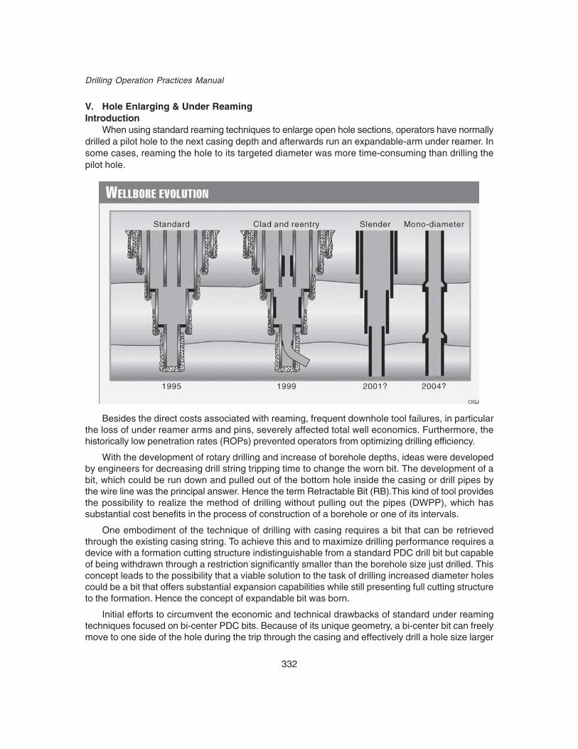
332
Drilling Operation Practices Manual
V. Hole Enlarging & Under ReamingIntroduction
When using standard reaming techniques to enlarge open hole sections, operators have normallydrilled a pilot hole to the next casing depth and afterwards run an expandable-arm under reamer. Insome cases, reaming the hole to its targeted diameter was more time-consuming than drilling thepilot hole.
Besides the direct costs associated with reaming, frequent downhole tool failures, in particularthe loss of under reamer arms and pins, severely affected total well economics. Furthermore, thehistorically low penetration rates (ROPs) prevented operators from optimizing drilling efficiency.
With the development of rotary drilling and increase of borehole depths, ideas were developedby engineers for decreasing drill string tripping time to change the worn bit. The development of abit, which could be run down and pulled out of the bottom hole inside the casing or drill pipes bythe wire line was the principal answer. Hence the term Retractable Bit (RB).This kind of tool providesthe possibility to realize the method of drilling without pulling out the pipes (DWPP), which hassubstantial cost benefits in the process of construction of a borehole or one of its intervals.
One embodiment of the technique of drilling with casing requires a bit that can be retrievedthrough the existing casing string. To achieve this and to maximize drilling performance requires adevice with a formation cutting structure indistinguishable from a standard PDC drill bit but capableof being withdrawn through a restriction significantly smaller than the borehole size just drilled. Thisconcept leads to the possibility that a viable solution to the task of drilling increased diameter holescould be a bit that offers substantial expansion capabilities while still presenting full cutting structureto the formation. Hence the concept of expandable bit was born.
Initial efforts to circumvent the economic and technical drawbacks of standard under reamingtechniques focused on bi-center PDC bits. Because of its unique geometry, a bi-center bit can freelymove to one side of the hole during the trip through the casing and effectively drill a hole size larger

333
Emerging Technologies
than the inner diameter of the casing through which it passes. Although a step-change improvementover standard under reaming, bi-center bits are not without operational problems that can negativelyaffect drilling costs. Warren, et al., perhaps best amplified the difficulties associated with the use ofbi-center bits for opening holes. Foremost among the problems are deviation tendencies that makethese bits extremely weight sensitive when run on rotary drilling assemblies. Because only stabilizersmatching the pass-through diameter can be used, deviation control is difficult.
The cocking (walking) tendencies of bi-center bits generate unusual wear patterns, making itchallenging to affect proper stabilization. This propensity places severe limitations on rotary speed,thus lowering penetration rates. Aside from low penetration rates, bi-center bits have not eliminateddrill string failures, abnormal tool wear, and instances where the reamed interval was not as largeas that stipulated in the well plan.
In the majority of wells drilled onshore Venezuela, the shortcomings of bi-center bits in reamingoperations were even more pronounced, particularly in the upper sections, which are highly proneto bit balling. As such, the shallower fluid courses of one-piece bi-center bits significantly restricthole cleaning in those intervals. Furthermore, the abnormal pressure characteristic of Venezuelanwells requires the setting of maximum-diameter liners throughout the well bore to minimize holeloss. This requirement and the wide variance of formation composition require flexibility in the sizeand type of pilot bits and bottom hole assemblies. Standard bi-center bits do not afford this flexibility.
The ability to drill and ream in a single pass has become even more advantageous as the globaltrend toward deeper, high pressure, high temperature wells increases. Because of the extra casingstrings and longer intervals often drilled through unstable or encroaching formations, operators haverecognized the enormous economic advantages of simultaneous drilling and reaming.
Contemporary exploration trends and the documented limitations of both bi-center and traditionalhole opening technology spurred the development of the ream-while-drilling tool.
The ream-while-drilling (RWD) tool is a two-piece system that, unlike traditional under reamers,incorporates no moving parts. This design eliminates the risk of leaving metal parts, such as underreamer arms and pins, in the hole. The first section of the tool consists of the pilot bit; the secondis essentially a tube incorporating either four or five fixed blades with PDC cutters. The position offluid jets on only one side of the tool enables eccentric rotary movement to widen the pilot hole. Byvirtue of the two-piece configuration, the type and size of both the pilot assembly and bit dependsonly on the design of the specific tool. Thus, either a PDC or roller cone bit can be used, dependingon the formation composition.
Under Reaming TechnologiesUnder reaming is a complex market consisting of at least 22 drilling applications. Under reaming
offers several product options, including bi-center bits, reaming wing tools, expandable bits andunder reamers.
In terms of product selection and application, the variety of available options presents a dilemmato the drilling professional. The accompanying box provides a list of strengths and limitations forretractable drill bits, bi-center bits, reaming wing tools, and under reamers. Two hole-size categories-171/2 to 36 in. and 43/4 to 171/2 in.-were created to aid in the analysis.This was also intended toidentify any trends that may emerge as to product preference and hole size.
Because of the technical differences between hole openers and under reamers, hole openershave been excluded from the market analysis. Hole openers start to enlarge an existing pilot holefrom the surface of the well bore and contain fixed cutters of a predetermined diameter.

334
Drilling Operation Practices Manual
Conversely, under reamers enlarge the hole below a restricted tubular bore. The cutters arekept closed during the pass-through and are activated once the tool reaches the point that requiresunder reaming. Turning the pumps off deactivates the cutters with this technology.

335
Emerging Technologies
1. Under reamersOriginally, under reamers were only used to under ream previously drilled holes, involving an
additional trip. Typical design features included flow or weight-activated arms that expanded on apivot-bearing mechanism.
For the purpose of drilling oversized hole sections, the Anderreamer uses aunique combination of mechanical and hydraulic mechanisms to extend the cutter blocks.
An example of the limitations associated with this type of technology can be seen in runs wheretraditional arm-type under reamers have led to failures, often resulting in a sidetrack.
Reportedly, under reamers have difficulty coping with deviated wells and hard chalk. This hasraised concerns regarding the effect of bending stresses on the body and connections.
Another problematic area includes mud packing. When this occurs below the arms, it can preventthem from closing in, making it extremely difficult to pull out of hole.
Historically, these factors have swayed decision making in regards to its use. Even today, underreamers still have a way to go in terms of improving mechanical integrity and shedding a poor image.
To improve the mechanical integrity of traditional arm type under reamers, several things happened.First, the development of polycrystalline diamond compact cutters eliminated problems associatewith mud packing and arm breakage. Thus, typical tool life was extended to 10 runs or more.
A further procedural innovation involved the removal of all cutters from worn roller cones, replacingthese with new cutters. These cutters were stub-welded in place once fatigue became an issue.
Three-cone under reamers have been capable of enlarging holes by as much as 50%, typicallyselected according to formation type so as to optimize performance. The tools also allowed fullvolume circulation at all times.
It is convenient to classify the various reamers as either drilling or reaming types. The reamingtype serves only to enlargen an existing hole, involving complete section redrill.
Conversely, the drilling type allows for the simultaneous reaming of a pilot hole as it is drilled.It can also be used to under ream existing holes. Its design allows mudflow to be diverted to the bitor can even be used with guidance system such as a bullnose for pilot-hole reentry.

336
Drilling Operation Practices Manual
The latter has been reported to give good hold or slight build tendencies, depending on formationand other factors. Thus, its performance resembles a packed-hole assembly.
2. Retractable Bits (RB)First projects of DWPP occurred at the beginning of 20th century. Drilling method with RB and
DHM was proposed in 1902. The attempts were made after the First World War of this methodrealization in Poland, and a little bit later in France (1928). Over the same period (20s-30s) greatinterest to RB was displayed in the USA. The bit designs with retractable blades operated worsethan standard two-blade drag drilling bits (“fish-tail” bits). In 30s, three-cone rock bits were introducedas the main type of rock destruction tool. First designs of cone rock RB were patented in the USAbefore the Second World War.
This kind of tool provides the possibility to realize the method of drilling without pulling out thepipes (DWPP), which affects substantially the process of construction of a borehole or one of itsintervals. Subsequent to the development of rotary drilling and the increase of borehole depths, theconcept of decreasing drillstring round-trip time to change the worn bit was devised.
The development of a bit that could be run in and pulled out of the bottomhole inside the casingor drillpipe, using a wireline or drilling mud circulation was a logical solution.
These bits were used in two modes:
(1) working - for bottomhole destruction(2) transport - for moving inside the pipe
The bit name, Retractable Bit (RB) derived of this application.
The use of RB allows drilling without pulling out the pipe (DWPP) and substantially affects theprocess of construction of a borehole or one of its intervals. DWPP features are as follows:
• continuous flushing of the borehole during the RB operational cycle: running in, drilling,pulling out
• replacement of the different purpose tools (drilling, coring, and milling) without pulling outdrillpipes
• carrying out logging operations without pulling out drillpipes• relief of the workload on drilling rig crews
This required among others:• more complicated bit design• special or larger ID flush joint drillpipe• special design BHA, including retrievable BHA (RBHA) and connection to drillstring• latch and seal unit for RBHA
The real advantage of the RB technology - simultaneous borehole drilling and casing.
Unfortunately, the quality of standard casing pipes and particularly types of thread connectionsdid not allow using them for DWPP especially in hard formations. Nevertheless, this trend of RB usecould be one of the major tasks for future research, because it brought revolutionary changes in theentire drilling process.
RB Technology Prospects1) Drilling with casing – this is most promising trend in cost-effective technologies for 21st
century.2) Super-long boreholes drilling – RB could provide drill string tripping timesaving, better well
control and borehole walls stability in 10-15 km long wells.
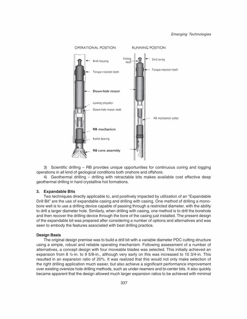
337
Emerging Technologies
3) Scientific drilling – RB provides unique opportunities for continuous coring and loggingoperations in all kind of geological conditions both onshore and offshore.
4) Geothermal drilling – drilling with retractable bits makes available cost effective deepgeothermal drilling in hard crystalline hot formations.
3. Expandable BitsTwo techniques directly applicable to, and positively impacted by utilization of an “Expandable
Drill Bit” are the use of expandable casing and drilling with casing. One method of drilling a mono-bore well is to use a drilling device capable of passing through a restricted diameter, with the abilityto drill a larger diameter hole. Similarly, when drilling with casing, one method is to drill the boreholeand then recover the drilling device through the bore of the casing just installed. The present designof the expandable bit was prepared after considering a number of options and alternatives and wasseen to embody the features associated with best drilling practice.
Design BasisThe original design premise was to build a drill bit with a variable diameter PDC cutting structure
using a simple, robust and reliable operating mechanism. Following assessment of a number ofalternatives, a concept design with four moveable blades was selected. This initially achieved anexpansion from 8 ½-in. to 9 5/8-in., although very early on this was increased to 10 3/4-in. Thisresulted in an expansion ratio of 20%. It was realized that this would not only make selection ofthe right drilling application much easier, but also achieve a significant performance improvementover existing oversize hole drilling methods, such as under-reamers and bi-center bits. It also quicklybecame apparent that the design allowed much larger expansion ratios to be achieved with minimal

338
Drilling Operation Practices Manual
alterations in the blade design. The expansion mechanism is entirely hydraulically actuated by thepressure differential from fluid flowing through the bit. An internal coil spring is incorporated to returnthe blades to the closed position. This would occur every time flow through the bit stopped.
Operational Feedback and Product DevelopmentIt was evident that debris contamination along the underside of the blades could prevent the bit
from closing satisfactorily. Also, drilling debris was entrained within parts of the blade guide slots.
It was recognised that preventing ingress and entrapment of debris to the working parts of thebit would be impossible, so the alternative was to insure, as much as possible, that no entrapmentcould occur. Accordingly, the slots in the head were considerably relieved, retaining only sufficientmaterial to ensure necessary structural integrity. The lower faces of the blades were also re-profiled,with a blunted knife-edge, to displace any solids accumulating underneath them. (The slots in theblades, engaging with the return pins were replaced with grooves on the front and back faces andthe pins were re-designed accordingly.)
In an attempt to provide a pressure sensitive open/closed indicator, small by-pass ports weredrilled into the head of the bit immediately below the lower face of each blade. The lower face ofeach blade was provided with a rubber plug, to prevent flow when the bit was closed. The portswould have the additional feature of washing out the lower face of each blade during drilling operations.
Some damage was evident to the bore of the hydraulic cylinder, caused by contact with theouter diameter of the piston. Although the original design concept had attempted to keep the numberof parts to an absolute minimum, to increase reliability, it was decided to fit bronze wear ringsbetween the piston/cylinder and cylinder/mandrel interfaces. These were retrofitted to the prototypeand could easily be replaced in the field. Flushing ports were also introduced into the hydrauliccylinder to enable cleaning of the actuating chamber and spring chamber without necessitating strip-down during field operations.
The expandable drill bit’s closed configuration is shown on the leftwith the expanded mode on the right. During field tests with Unocalin Indonesia, weight on bit required to achieve a specificed controlledpenetration rate was 30% lower than for offset tricone runs.

339
Emerging Technologies
Summary and Future DevelopmentsDevelopments of the expandable bit have proved the concept to be feasible and practical.
Supported by continuous development in association with Unocal, this project has providedperformance improvement and addressed all necessary operational issues.
4. Bi-center bits
Fig. 4.
340
Drilling Operation Practices Manual
In 1994, bi-center bits were introduced, which contained new technology. For the first time, asingle tool could reliably be used to simultaneously drill and under ream, even in highly directionalapplications, all with no moving parts. The results were fewer trips, fewer rotating hours, and less“problem” time. The only major draw back to using bi-center bits has been that they could not beused to drill out cement, float equipment, and casing guide shoes. It was required that a conventionaldrill bit be used first to drill out into new formation, then a trip was needed to pick up the bi-centerbit. In 1999, advancements in bi-center technology have resulted in a bi-center bit that can be usedto drill out and then continue to drill ahead.
Gradually, increased demand for these bits highlighted certain technological limitations, includingpoor directional drilling performance. Essentially, this was linked to the lack of a full-gauge stabilizerabove the bi-center bit, resulting in bottomhole assembly (BHA) stabilization issues. Withoutstabilization, there was a need to depend almost entirely on the bent motor housing to steer.
BHAs using bi-center bits tended to have a problem with inclination control. Consequently, tomake changes in inclination, drillers spent a lot of time slide drilling, which can be difficult at thebest of times, let alone with the added complication of running a bit that is geometrically unstable.From this perspective, there was an understandable apprehension towards running bi-center bits. Assteerability issues continued to hinder directional performance, bi-center bit manufacturers have foundways to improve BHA behavior. These companies realized that bi-center bits could to an extent besteered by weight alone. They also found that longer bit profiles helped to stabilize BHA performance.
Today, bi-center bits are used in hard formations as they are perceived to be more robust thantraditional arm under reamers. On the other hand, under reamers tend to be preferred in softerformations as their application can lead to impressive gains in penetration rates while providing anincreased time window to conduct operations in swelling formations.
The success of bi-center bits removed the need for hole openers in many applications, eliminatingthe need to drill the interval twice. From the drilling engineers’ point of view, a single integralcomponent reduced risk and cost as compared to two or three. All these factors came together toconfirm the place of the bi-center bit in the industry.
Bi-center bits often produce excitation force required to induce vibrations that are then detrimentalto drillstring and BHA components, It is also felt that they do not drill out shoes as efficiently aspredicted. Finally recent calliper logs run in the GOM illustrated that large sections of the wellborehad not been enlarge “opened up” at all.
5. Reaming Wing ToolAnother technology is the reaming wing tool. This technology features a polycrystalline diamond
compact bit with a ream while drilling capability. This tool differs from bi-center bits in that it featuresa two-piece design, allowing for greater flexibility in pilot bit selection. Directional control is conductedthrough a steerable motor. With all factors duly considered reaming wing tools may have somepotential for use in deep open water applications, notably in shallow high angle wellbore fielddevelopments.
DesignThe ream-while-drilling (RWD) tool is a two-piece system that, unlike traditional under reamers,
incorporates no moving parts (fig. 1).
This design eliminates the risk of leaving metal parts, such as under reamer arms and pins, inthe hole. The first section of the tool consists of the pilot bit; the second is essentially a tube

341
Emerging Technologies
incorporating either four or five fixed blades with PDC cutters. The position of fluid jets on only oneside of the tool enables eccentric rotary movement to widen the pilot hole.
The pass-through is the drift diameter of the casing or the liner through which the system mustpass. Drill size is the final drilled hole diameter. The drill size of the targeted section, in conjunctionwith the pass-through diameter stipulated in the well objectives, determines the pilot bit diameter.
Fig. 1. By virtue of the two-piece configuration,the type and size of both the pilot assemblyand bit depends only on the design of thespecific tool. Thus, either a PDC or roller conebit can be used, depending on the formationcomposition.
Fig. 2. The geometry of the RWD tool revolvesaround three interrelated diameters: passthrough, drill size, and pilot bit
The geometry allows the tool to adapt easily to the maximum diameter of the liner or casing inwhich it must pass. Upon rotation, the tool is then able to widen the hole to its programmed finaldiameter.
The leading, or hole opening, blade creates a smooth transition from the pass-through size tothe drill size, providing faster stabilization of the system. The pilot bit stabilization pad offsets thenet imbalance force of the reamer blades, thus providing the additional stabilization not possiblewith bi-center bits. Basically, the stabilization pads force rotation around the center of the pilot hole,ensuring the drilling of a full-size well bore. Both the pilot hole size and the extent of the imbalanceforce generated determine the size of the gauge pad.
The reamer wing has carbide-supported edge PDC cutters. The shape of these new-generationcutters strengthens the diamond edge and delays the onset of fracture and cutter wear. By spreadingthe cutter arrangement across the profile of the tool, the RWD tool designers successfully facilitatedeven load distribution.

342
Drilling Operation Practices Manual
The cutter surfaces are highly polished, which is especially advantageous when sections proneto bit balling are drilled, such as those encountered in the upper hole of Venezuelan wells. PolishedPDC cutters have a friction coefficient of 0.1, or that of ice sliding on ice. Polished cutters reducethe penetration rate limitations posed by the built-up edge that forms when an amount of drilledformation is not removed and subsequently attaches itself to the leading edge of the cutter. Polishedcutters reduce the shear forces that restrict cuttings removal and limit penetration rates. The polishingprocess also removes any microscopic imperfections in the cutter, further enhancing cutter durability.
The future of under-reaming technologyThe three main characteristics of the under reaming market, increased production, cost cutting,
and technical innovation in well design show promise for the future. Moreover, strong market driversin the short, medium, and long term will tend to encourage conditions apt for growth.
Increased productionIncreased production is important for two major reasons. First, depleted reservoirs result in lower
reservoir pressures and poorer rock mechanics, further heightening the likelihood of sand productivity.In these instances, to preserve or improve production rates, provision must be made for sandexclusion through pre-wrapped screens or gravel packs.
Consequently, the need for enlarging holes to place new sand screens and gravel packs alsoarises. Eventually, the demand for remedial work such as drilling through failed screens will placeadditional demand on under reaming technologies.
Depleted reservoirs are also likely to result in transition from oil to gas production. As such,the use of under reaming technologies to configure larger bore casing strings can be viewed as apreferred method of improving productivity by maximizing the size of the borehole in the reservoirsection of the well.
The bracket of increased production also covers older platforms. Decommissioning has provedto be complicated, time consuming, and expensive. These costs tend to dissuade operators fromsuch activities, enhancing the appeal for extending platform life. This can also heighten demand,as certain technical restrictions can be associated with older platforms.
These restrictions include the availability of conductor slots and the size of blowout preventers,which restricts bit diameters and conductor placement. Both of these examples make under reamingan attractive option, as it overcomes such limitations while maximizing the configuration of casingstrings.
Finally, under reaming technologies can be applied towards sidetracking and multilateral drillingapplications where hole enlargement through existing casing strings provide an attractive option.

343
Emerging Technologies
VI. Laser DrillingIntroduction
Laser Drilling is a revolutionary method of using laser beams to drill oil and gas wells. The termLASER is an acronym for Light Amplification by Stimulated Emission of Radiation. Albert Einstein,in 1917, predicted the possibility of stimulated emission (generation of photons or discrete bundlesof energy via transitions between atomic or molecular energy levels). The first working laser wasmade by Theodore H. Maiman in 1960 at HughesResearch Laboratories in Malibu, California.
• “To lase” means “to produce coherent(consisting of waves of a single wavelength, inwhich all the waves reinforce one another) light”and also “to cut or treat with coherent light”
• A laser is basically a device that convertsenergy of some form (electrical, chemical, heat,etc.) into photons (electromagnetic radiation)
• The photons created through stimulatedemission form a narrow beam ofmonochromatic, coherent light that whenfocused into an intense beam can be used toablate {spall (chip/ fragment), fuse (melt) and/or vaporize} a target depending on the powerdelivered.
• Lasers can operate in continuous-wave (CW),pulsed, and repetitively pulsed (RP) modes.
Laser Construction
Principal components1. Active laser medium2. External energy pump3. Mirror4. Partial mirror5. Laser beam
Application of Lasers• Medical: In surgery – as a scalpel, to reattach retinas and to stitch up incisions after
surgery by fusing together skin• Entertainment & Advertising: These use lasers that are in the visible spectrum to paint images
in the air.
1
3
5
24
ABSORPTION
EXCTTATION
SPONTANEOUSEMISSION
POPULATION OFMETASTABLE STATE ANDBUILD UP OF STIMULATEDEMISSION ALONG AXIS
STIMULATEDEMISSION
RETURN TOGROUND STATE

344
Drilling Operation Practices Manual
• Computers and Music: One popular use of lasers is optical drives.• Metal working: Lasers allow better cuts on metals and the welding of dissimilar metals
without the use of a flux. • General Purposes: Lasers are also used to align pipes and wheels, measure speed and
distances, read bar codes etc.• Defence: Lasers track & destroy missiles etc.
Oil & Gas Industry: Projects are being carried out to drill & complete oil and gas wells with lasers.Given below are a few of the expected applications in oil & gas industry
• vertical & directional (including extended reach) drilling,• seismic shot holes,• Cutting windows for side tracking and laterals• cutting trenches for pipelines,• small diameter exploratory wells,• horizontal and slanted wells,• removal of objects lost downhole that would normally require drill out or fishing operations.• primary perforation to create the path between the wellbore and reservoir• extend perforations to connect additional reservoir rock to the wellbore (fracturing)• Laser technology can also be applied to other arrears that require rock removal, such as,
mining, excavation, tunneling, nuclear reactor decommissioning, archeological investigation,drilling volcano artificial chimneys for pressure relief, geothermal wells, etc.
Types of lasersThe laser medium can be a solid, gas, liquid or semiconductor. Lasers are commonly designated
by the type of lasing material employed:• Solid-state lasers• Gas lasers• Excimer lasers• Dye lasers• Semiconductor lasers or diode lasers• Fiber lasers
Laser Drilling Concept• Laser applies infrared energy to the working face of the borehole and ablates the rock by
spallation, fusion or vaporization.• The down hole assembly includes sensors that measure standard geophysical formation
information, as well as imaging of the borehole wall, all in real time.• Excavated material is carried to the surface as solid particles / vapour.• When desired, some or all of the excavated material is melted and forced into and against
the wall rock to line well bores for well stabilization and abnormal pressure control.• When the well bore reaches its target depth, the well is completed by using the same
laser energy to perforate through the ceramic casing.• All this is done in one pass without removing the drill string from the hole.
Laser Drilling ActionHigh power lasers can be used to destroy rock in two ways:• by weakening the rock prior to application of mechanical tools

345
Emerging Technologies
• by direct rock destruction via ablation. Each of the three methods of ablating rock (spalling,fusing or vaporizing) may have specific applications for natural gas drilling and completion.
There are three processes by which lasers might transfer energy into a rock target:• Absorption• Reflection• Scattering
It is the absorbed energy that gives rise to rock heating and destruction. Reflection and scatteringrepresent energy losses in the process of rock destruction. The degree to which energy is lostdictates the effectiveness of the laser’s ability to spall, fuse or vaporize rock.
Basic benefits of laser drilling• Non-contact process (no tooling wear or breakage)• Highly accurate and precise control of heat input• Ability to produce small diameter holes with high aspect ratios• Ease of programming and ready adaptability to automation• No out-of-balance or out-of-axis turning is expected to occur with a laser drilled hole because
photons travel in straight paths.
Benefits to Oil & Gas Drilling• Could significantly increase the rate of penetration (ROP) and thus reduces overall drilling
costs• Since a sheath will be formed around the hole drilled, casing & piping can be eliminated/
along with all equipment and operations (like tripping etc.) associated with this. Likewisedownhole problems like caving, loss etc. are reduced.
• Provides perforating and side-tracking capabilities.
Also eliminates/reduces• Rig size• Power consumption• Mud/chemical requirement• Bit costs
Laser Drilling Research WorldwideIn 1994, the U.S. Congress issued a mandate to transfer the laser technology developed for
the U.S. Department of Defense’s Star Wars project to civilian applications. In 1997, the GasResearch Institute called for proposals to revolutionize drilling. ‘Colorado School of Mines’ and‘Solutions Engineering’ submitted proposals for applying star wars laser to drill and complete wells.They demonstrated the feasibility of using high power lasers for oil and gas applications. Consortiumpartners in this research with DOE were Colorado School of Mines, Gas Technology Institute, U.S.Geological Survey, DOE/NGOTP (Natural Gas and Oil Technology Partnership), U.S. Air Force,Argonne National Laboratories, Halliburton, N.A. Technologies, Parker Geoscience, OccidentalPetroleum, Boeing Intellectual Property Business, IPG Photonics (IPG) and the Venezuelan NationalOil Company (PDVSA).
Research Objectives• To obtain much more precise measurements of the energy requirements needed to transmit
light from surface lasers down a borehole with enough power to bore through rocks as muchas 6000M or more below the surface.

346
Drilling Operation Practices Manual
• To determine if sending the laser light in sharp pulses, rather than as a continuous stream,could further increase the rate of rock penetration. Pulsed lasers have been used for betterperformance in cutting rocks.
• To determine if lasers can be used in the presence of drilling fluids. The technical challengewill be to determine whether too much laser energy is expended to vaporize and clear awaythe fluid where the drilling is occurring.
• A variety of lasers have been used in the research. The following table shows the lasers,location, and laser properties.
LASER Location Wave Powerlength Used(µm) (kW)
Mid-Infrared Advanced US Army, White Sands, NM 2.6 to 900Chemical Laser (MIRACL) 4.2
Chemical Oxygen Iodine Kirtland Air Force Base, 1.315 8Laser (COIL) Albuquerque, NM
Pulsed CO Laser Lebedev Institute, Moscow, Russia 5 to 6 6
Pulsed CO2 Laser Lebedev Institute, Moscow, Russia 10.6 6
CO2 Laser Wright Patterson Air Force Base, Dayton, OH 10.6 8
CO2 Laser Argonne National Labs, Chicago, IL 10.6 10
Nd:YAG Argonne National Labs, Chicago, IL 1.06 6
Direct Diode Native American Technologies, Golden, CO 0.8 4
Figure above shows experimental set-up for Nd:YAG Laser interacting with rock

347
Emerging Technologies
A comparison of laser parameters for industrial lasers at 4KW power output is given in tablebelow.
Spectroscopy is used in determining the amount of energy reflected, emitted, and scattered bythe rock. Low reflectance indicates that more energy is absorbed into the rock. Even though CO2,CO and MIRACL lasers have the greatest absorption, they may not be the best candidates forprototype/field applications. The Direct Diode, Nd:YAG and COIL have lower absorption but theyhave better prototype/field qualities such as durability, portability, downhole energy delivery and lowerenvironmental impact. However, It has been determined that power not wavelength controls rockremoval rate.
The size of lasers varies from the US Army’s MIRACL which is the size of a small refinery tothe Direct Diode laser which is about of the size of a shoe box. The US Air Force COIL has beenminiaturized, as part of the airborne laser defense system, to operate inside a Boeing 747.
Sandstone, Limestone, Shale, Granite, Concrete and Salt were tested during the course of theresearch. Rocks can be chipped, melted or vaporized by a laser beam. It is controlled by diversemechanisms that are function of both the rock properties and the laser parameters. In every rocktype tested, the porosity and permeability were increased and the elastic moduli were altered toweaken the rock. This process in primarily due to the creation of microfractures and dehydration ofclays. Even though the melted material in the wall of the hole is impermeable, the rock propertiesbehind the melted sheath are improved.
ROP as a function of Specific Energy and Specific PowerSpecific energy (SE) is a measure of the efficiency of the rock destruction technique. In other
words specific energy (SE) is the energy required to remove a unit volume of rock and hence it is acritical rock property data that can be used to determine both the technical and economic feasibilityof laser oil and gas well drilling. When a high power laser beam is applied on a rock, it can removethe rock by thermal-spallation, melting or vaporization depending on the applied laser energy andthe way the energy is applied. The most efficient rock removal mechanism would be the one thatrequires the minimum energy to remove a unit volume of rock.
The specific energy or the amount of energy required to remove a unit volume of rock and ismathematically defined as follows:

348
Drilling Operation Practices Manual
WhereP = Power Input (Watts)DV/dt = Volume Time Derivative (cm3/sec)
Hence Specific Energy varies inversely as the efficiency of the laser cutting process.
Also Specific power (Power Density) is the power per unit area, Pc, (kW/cm2). ROP is relatedto specific power and specific energy by Pc / SE (cm/s). The most efficient rock removal mechanismwould be the one that requires the minimum energy to remove a unit volume of rock. To increaseROP, techniques that have high specific power and low specific energy should be used.
Above graph shows a comparison of various techniques for rock drilling and boring in terms ofrate of penetration, specific power and specific energy. (1) Percussive drills (small holes); (2) Rotarydrills; (3) Drill-and-blast tunneling; (4) Raise-and-tunnel-boring machines; (5) Flame jets; (6) Laserspallation; (7) Future laser spallation.
Figure above reveals that to increase ROP of rock breaking, one should use techniques thathave high specific power and low specific energy. With better laser head and assisting purging systemdesigns, laser drilling would be the next generation drilling system.
Secondary effects like melting, re-melting, absorption of the laser energy by the plasma andthe plume, etc., reduce the efficiency of laser cutting and are dependant on mineralogy, thermal
dtdV / P
Reoved VolumeInputEnergy
SE ==
33
2
cm
kJ
/seccm
kWcm
second cm
kW
==⎥⎦⎤
⎢⎣⎡
=

349
Emerging Technologies
properties and rock properties. This underlines the need for an efficient debris and vapor removalsystem.
Some important laser drilling research resultsMany organizations and institutes are carrying out research in laser drilling The following
conditions have been varied during the experiments: rock type, time on target (heat input), beamdirection (horizontal or vertical), continuous and pulsed, stress orientation, saturation (air, methane,oil, fresh and salt water), lased through drilling mud and fresh water, sample shape and purge assistgas. A few relevant research results are summarized below.1. The minimum specific energies (energy required to remove unit volume of rock, SE, kJ/cm3) fortwo typical reservoir rocks tested in the studies are listed in the Table. It is seen that each rocktype has a set of optimal laser parameters to minimize SE. Shale samples recorded the lowest SEvalues as compared with limestone and sandstone samples. One can see that rock removalmechanisms can be changed between spalling and melting through controlling either the specificpower or exposure time.
2. Study of samples from rock samples drilled with high-power lasersFigure of Petrographic thin section of Berea gray sandstone showing the lased hole and the
four concentric alteration zones• Layer–1 is a discontinuous layer. This layer will not be formed if the laser melt is removed
before solidification.• Layer-2 is a continuous layer. This layer forms a sheath of petrified silica around the lased
hole. The thickness of layer-2 depends upon the silica content of the lased area, the porosity,the power of the laser, and the thermal conductivity of the rock. This layer shows potentialfor possibly replacing conventional casing steel used in oil and gas wells.
Rock Laser Beam Average Specific Exposure Specific Energy,kJ/cm3
Type used spot size, power power times,smm W W.Cm2
19 2020 712 2.6 (Spalling)
c w 19 2210 780 3.5 (spalling + slight melting)
Berea CO2 12.7 2210 1,745 0.5 6.5 (spalling + medium melting)
grat 12.7 3000 2,369 30.0 (heavy melting)sandstone
534 4,217 0.52 (spalling)
415 3,280 1.79 (spalling)
Shale Pulsed 330 2,610 0.5 2.71 (spalling)
Nd: YAG 12.5 262 2,070 3.53 (spalling)
202 1,590 5.54 (spalling)
534 4,217 1.0 3.6 (medium melting)

350
Drilling Operation Practices Manual
• Layer-3 is wider than the other three layers. Layer-3 represents a mechanical support tolayer-2. Both layers may indeed provide adequate support for oil and gas boreholes.
• Layer-4 represents the external limit of the laser thermal effect. Crystals are not transformedinto other minerals but are instead mechanically deformed and slightly burnt.
3. Overlapping multiple small laser beams method to drill large diameter and deep holes.• To cover large diameter area (8-1/2 or greater), either the small spot size beam has to be
scanned or multiple such beams are overlapped.
• Each laser beam can spall a shallow hole as big as the spot size usually 1.27 cm indiameter.
• Since some relaxation time is needed for avoiding melting of rock, the overlapped beamswill fire on the rock sequentially or in groups to create a layer of nearly circular work faceof a desired diameter.
• The rock fragments from this layer will be instantaneously removed with the help of thepurging and flushing system.
Fresh rock
Layer-4
Layer-3
Layer-2
Layer-1
Lased-hole

351
Emerging Technologies
• Then laser beams will fire again to spall the second layer of rock. Layer by layer, a deephole will be drilled out until the desired depth reaches
• Laser parameters can be controlled very precisely to achieve spallation, melting orvaporization the rock, depending on the application required.
• The phase change in the rock depends mainly on;• the rock type,• thermal properties and• measured average power• Tests on Nd:YAG laser shows that;• Nd:YAG laser can perforate the rock as efficiently as the other types of high power lasers• the permeability of the rock lased by pulsed Nd:Yag laser beam increases up to 566%
compared to non-lased rocks due to clay dehydration and micro-fractures induced by thehigh temperature gradient.
Linear Nd:YAG Laser Track Test Samples with Constant Focal PositionChange Rate for Sandstone, Limestone and Shale Identifying Laser-RockReaction Zones and Calculated Power Densities.

352
Drilling Operation Practices Manual
Summary of Other Experimental Results• Measured SE increases very quickly with beam exposure time indicating the effects of energy
consuming secondary processes.• Temperature higher than 6500C (12000F) was recorded on the tested rock that was exposed
to a kilowatt level laser beam.• Rates of heat diffusion in rocks are easily and quickly overrun by absorbed energy transfer
rates from the laser beam to the rock. As absorbed energy outpaces heat diffusion,temperatures rise to the minerals’ melting points and beyond, quickly elevating SE values.
• A laser is able to spall and melt rock through water, although laser energy at thesewavelengths is readily absorbed as it passes through the water to the sample.
• High power laser-rock interaction tests have proven that lasers can penetrate all rock typesincluding granite, much faster than conventional methods and other non-conventional methods.Laser can also induce fractures in the rocks by thermal expansion.
• The application of high power lasers can also enhances rock properties such as permeabilityand porosity. (Examination of more than 50 lased samples of different rocks - sandstones,limestones, dolomites, shales, and granites indicates this).
• A higher percentage of quartz in the sample will result in higher melting point for the rock,therefore requiring more energy to melt and more energy to vaporize.
• Rock properties (type, porosity, moisture content, etc.) effect laser drilling effectivenessand some rocks may have optimum (minimum) SEs higher than others, the consequenceof which is slower drilling.
• Sandstones saturated with water spall faster. More rock can be removed before meltingcommences.
• Applying 5.34 kW Ytterbium-doped multiclad fiber laser on multiple samples of granite,cement and steel confirmed that the laser was capable of penetrating these materials undera variety of conditions.
• Operating a high power laser in underbalanced conditions showed the laser’s ability to performat downhole conditions without requiring a supplemental assist purge system
Conclusions• Laser spallation shows 8 –100 times faster ROP than that of the conventional rock breaking
techniques because it has specific power as high as that of flame jets which is the highestamong the conventional methods and specific energy as low as that of most conventionalmethods.
• As it drills, the laser exposure creates a glass or ceramic liner that, potentially, could replacethe steel casing now required in boreholes. Eliminating the need for casing & drill-pipe wouldbe a big saving.
• The most energy efficient drilling can be achieved by maintaining laser intensities belowthe threshold for rock melting and vaporization.
• In narrow, deep holes, fragments of rock can block the beam, wasting energy. Multiple holesdrilled side by side with 1-inch-diameter collimated beams for a drill hole diameter of 8inches overcomes this problem.
• Super-pulsed (SP) CO2 laser beams were shown to efficiently drill deep, large diameterholes in petroleum rocks due to peak power 4 times higher than the average power, andthe beam’s pulse nature. The SP mode is more efficient than CW operation.
• Pulsed lasers cut faster & with less energy than continuous wave lasers. They have betterpenetration and fracturing, while a CW laser, which dumps too much power into the rock,causes it to melt and vaporize.
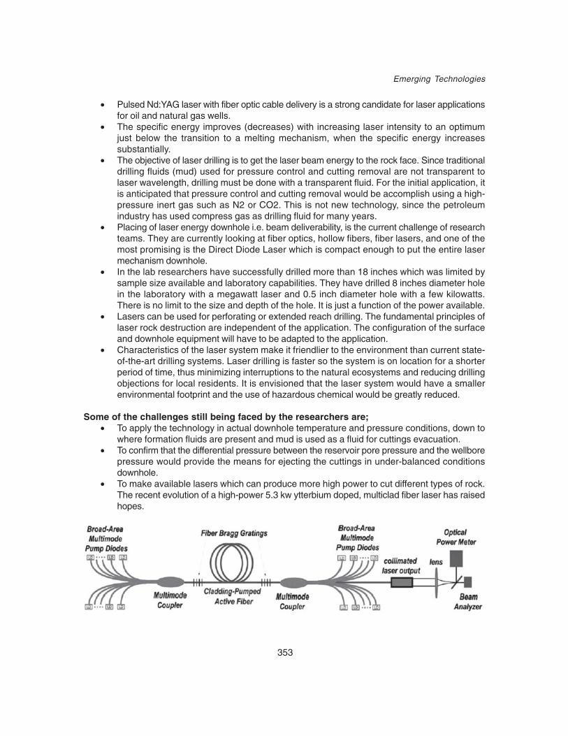
353
Emerging Technologies
• Pulsed Nd:YAG laser with fiber optic cable delivery is a strong candidate for laser applicationsfor oil and natural gas wells.
• The specific energy improves (decreases) with increasing laser intensity to an optimumjust below the transition to a melting mechanism, when the specific energy increasessubstantially.
• The objective of laser drilling is to get the laser beam energy to the rock face. Since traditionaldrilling fluids (mud) used for pressure control and cutting removal are not transparent tolaser wavelength, drilling must be done with a transparent fluid. For the initial application, itis anticipated that pressure control and cutting removal would be accomplish using a high-pressure inert gas such as N2 or CO2. This is not new technology, since the petroleumindustry has used compress gas as drilling fluid for many years.
• Placing of laser energy downhole i.e. beam deliverability, is the current challenge of researchteams. They are currently looking at fiber optics, hollow fibers, fiber lasers, and one of themost promising is the Direct Diode Laser which is compact enough to put the entire lasermechanism downhole.
• In the lab researchers have successfully drilled more than 18 inches which was limited bysample size available and laboratory capabilities. They have drilled 8 inches diameter holein the laboratory with a megawatt laser and 0.5 inch diameter hole with a few kilowatts.There is no limit to the size and depth of the hole. It is just a function of the power available.
• Lasers can be used for perforating or extended reach drilling. The fundamental principles oflaser rock destruction are independent of the application. The configuration of the surfaceand downhole equipment will have to be adapted to the application.
• Characteristics of the laser system make it friendlier to the environment than current state-of-the-art drilling systems. Laser drilling is faster so the system is on location for a shorterperiod of time, thus minimizing interruptions to the natural ecosystems and reducing drillingobjections for local residents. It is envisioned that the laser system would have a smallerenvironmental footprint and the use of hazardous chemical would be greatly reduced.
Some of the challenges still being faced by the researchers are;• To apply the technology in actual downhole temperature and pressure conditions, down to
where formation fluids are present and mud is used as a fluid for cuttings evacuation.• To confirm that the differential pressure between the reservoir pore pressure and the wellbore
pressure would provide the means for ejecting the cuttings in under-balanced conditionsdownhole.
• To make available lasers which can produce more high power to cut different types of rock.The recent evolution of a high-power 5.3 kw ytterbium doped, multiclad fiber laser has raisedhopes.

354
Drilling Operation Practices Manual
Diagram of a high power fiber laser (Courtesy of IPG Photonics, Inc.)• To devise methods to cool the laser head under the downhole conditions and the expected
working temperatures (~6000C or more).• To design a laser head that could put the power directly into the well bore and could
incorporate a sensor array for real-time monitoring down the hole. This type of precisionand range could eliminate many of the side-tracking and directional (lateral) drilling problems.
• To deliver power from Nd:YAG and fiber lasers through fibre optics to depths of 2000 M andmore.
• To fabricate fibre optic cables for the depths required• To determine & address the power loss issues• To built a working laser drilling prototype. Researchers expect that would be ready by 2010.
Currently options are being explored to develop a prototype drilling system using the SolidState Direct Diode Laser (DDL) and integrating the various components such as; pressurecontrol, solids removal. Beam deliverability, etc
• And finally to incorporate the laser technology and fiber optics with coiled tubing.
The laser drilling prototype may provide answers to many of these challenges.

355
References
REFERENCES
1. Drilling Operations Manual, IDT, ONGC, Dehradun, 19872. Operation and Maintenance Manual, BHEL Oil Well Drilling Rig, Vol. IV3. Offshore Technology, Unit-V, Lesson-IV, The Hoist, PES The University of Texas, Texas.4. Drilling Operations Manual, IDT, ONGC, Dehradun, 1994.5. Rotary Drilling Series, Unit-II, Lesson –III, Drilling a Straight hole, PES, The University of Texas,
Texas.6. Tool Pushers Course Materials, IDT, ONGC, Dehradun,7. Rabia H., Oil well Drilling Engineering- Principle & Practices, Graham and Trot man London.8. Rabia H, Fundamentals of Casing Design, Graham and Trotman London9. Moore L Preston, Drilling Practices Manual, Pennwell books, Pennwell Publishing Company,
Tulsa Oklahoma10. Rotary Drilling Series Unit - I, Lesson –II, The Bit, PES, The university of Texas Texas.11. Rotary Drilling Series, Unit-I, Lesson –III, The Drill Stem PES, The University of Texas,Texas.12. BHEL Manufacturing Catalogue Trichi13. OISD Standard -187 “Care and Use of Wire rope”, MOPNG, Govt. of India, 7th Floor, New Delhi
House, 27, Barakhamba Road, New Delhi -110001.14. Rotary Drilling Series, Unit-I, lesson –V, ‘The Block and Drilling Line’ PES, The University of
Texas, Texas.15. IADC, Houston, Texas.16. Well Control Manual, IDT, Dehradun, 200317. API-RP 7G (Sixteenth Edition August 1998)18. Trouble free drilling Vol.-I Stuck pipe prevention by John Metchill Dulberg, Engineering Inc.19. Stuck pipe prevention, Randy Smith, USA.20. Stuck pipe prevention Prentice Training Company Inc,21. Rotary Drilling Series, Unit –II, Lesson –IV, Casing & Cementing PES, The university of Texas,
Texas.22. Operations Manual Halliburton Services, Duncon, Oklahama23. Coring Manual Diamant Boart Petroleum Division Brussels ( Belgium)24. Composition and Properties of Drilling Fluids” Darley HCH and Gray G.R.25. Drilling Fluids Engineering Manual, Magcobar division Oilfield Products Group Dresser Industries
Inc. Houston, Texas.
BIBLIOGRAPHY1. McCray A.W and Cole F.W., Oil Well Drilling Technology, The English Book Depot, Dehradun.
2. Do’s and Don’ts for Drilling Engineers, IDT, ONGC, Dehradun.
3. Gatlin Carl, Petroleum Engineering Drilling & Well Completion, Prentice hall, Inc. EnglewoodCliffs, New Jersey.

ABOUT THE AUTHORS
V CHAKRAVARTY : He is B E (Mechanical Engineering) and has 25 years field & R&D experience inONGC. He has vide field experience in drilling operations in Bombay Offshore and on the Land Rigs.Heremained a regular faculty for Drilling Technology courses and specializes in the latest advancements.He has many papers to his credit. He has also authored many OISD standards.
R SHANKER : He is B E (Mechanical Engineering) and has wide experience in ONGC.He has fieldexperience in drilling operations in Eastern and Western Region. He remained a regular faculty for DrillingTechnology courses. He has presented many technical papers in various workshops/seminars and alsoauthored many OISD standards.
D DASGUPTA : He is B E (Mechanical Engineering) and has 13 years of field experience in cementingoperations in Agartalla, Assam and Karaikal. He is presently Head of Cementing and Cementing Material(CCM). He is a faculty for Cementing Technology topics.
A K JOSHI : He is M Sc (Chemistry) and joined ONGC in 1980. He has working experience as mudengineer on drilling rigs in Assam and Ankleshwer Assets. He is working in R & D section in Drilling FluidEngineering (DFE). He has many papers to his credit. He is a regular faculty for the drilling fluid relatedtopics.
R P AGGRAWAL : He is B E (Mechanical Engineering) and joined ONGC in 1982. He has workingexperience in drilling operations & directional drilling at various field of ONGC. He has worked in R & DDrilling in directional drilling. He remained a regular faculty for Drilling Technology courses.
P K DUBEY : He is B E (Mechanical Engineering) and joined ONGC in 1982. He has working experiencein drilling operations in Assam and directional drilling in Ankleshwar. He has worked in HRD and QHSEaudit in IDT and his present assignment is Drilling R & D in directional drilling. He specializes in QHSE.He is a regular faculty for Drilling Technology courses.
SANJAY KULKARNI : He is BE (Mechanical Engineering) and has varied experience of 24 years ofworking in the ONGC. He has worked on Jack up rigs as Driller / Tool Pusher at Bombay Offshore for 12years. He remained a regular faculty for Drilling Technology courses.
AJEETH X PARAPULLIL : He is BE (Mechanical Engineering) and has varied experience of 21yearsof working in the Oil Industry. He has worked on Jack up/Floater Rig as Driller / Tool Pusher for 10 years.He has also worked as Drilling Superintendent on Deep Exploratory High Pressure Gas Well for manyyears on the Land Rigs.
VINOD KUMAR : He is B E (Mechanical Engineering) and joined ONGC in 1988. He has workingexperience in drilling and cementing operations in Bombay Offshore and Assam assets. He has alsoworked as Safety Auditor, accredited to DNV, Singapore. He is presently posted in Drilling TechnologySchool and is a regular faculty for Drilling Technology courses.
ATANU BHATTACHARJEE : He is B E (Mechanical Engineering) and has 18 years field experience indrilling operations in KG and Assam assets. His present assignment is Drilling R &D and specializes incasing design. He is a regular faculty for casing design.
T R K SHERWANI : He is BE (Mechanical Engineering) and has varied experience of 22 years of workingin the Oil Industry. He has worked on Land rigs as Driller / Tool Pusher for 15 years. He has also experienceof working as Drilling Superintendent on deep wells of Assam Asset & as Fishing Engineer in AnkleshwarAsset. Working as Faculty in Well Control School and Stuck Pipe Prevention courses at IDT, Dehradun
G. VENKATSEWARAN : He is BE (Mechanical Engineering) and has varied experience of 21 Years ofworking in the Oil Industry. He has worked on Floater Rig as Driller / Tool Pusher for 10 years. He hasalso worked as Drilling Superintendent on Deep Exploratory High Pressure Gas Well for 3 years on theLand Rig. Working as Faculty in Well Control School and other training courses at IDT, Dehradun.


![Intern ONGC[1]](https://static.documents.pub/doc/80x56/54494eaaaf795998538b476d/intern-ongc1.jpg)


