Drinking Water Branch IRWA AWWA Drinking Water Guidance Manual Small and Medium Indiana Water Systems 10,000 or fewer persons served COMMUNITY SYSTEMS Prepared in association with Indiana Section American Water Works Association and Indiana Rural Water Association Presented to: Manual No. _________________________________ _________ System Name
Transcript
Drinking Water Branch IRWA AWWA
Drinking Water Guidance Manual Small and Medium Indiana Water Systems
10,000 or fewer persons served
COMMUNITY SYSTEMS
Prepared in association with Indiana Section American Water Works Association
and Indiana Rural Water Association Presented to: Manual No. _________________________________ _________ System Name
Drinking Water Branch IRWA AWWA
Drinking Water Guidance Manual Small and Medium Indiana Water Systems
10,000 or fewer persons served
COMMUNITY SYSTEMS
Prepared in association with Indiana Section American Water Works Association
and Indiana Rural Water Association
Indiana Department of Environmental Management
DRINKING WATER GUIDANCE MANUAL for Indiana small and medium community public water supplies
Introduction
This manual has been prepared to help the owners and operators of small community water systems (less than 10,000 people served). It also will assist you in meeting the requirements of Indiana’s public water supply regulations and the federal Safe Drinking Water Act. You will find information about the responsibilities of the Indiana Department of Environmental Management and its enforcement policies. But, this manual is not just about laws and regulations. It will help you with the operation and management of your system and assist you in planning for emergencies. There is information on public health considerations in supplying drinking water, and the reference sections list important contact names and telephone numbers, as well as information on where you can find other drinking water resources. Providing drinking water to the public (your family, neighbors and friends) is an important responsibility. You need to know about and understand drinking water regulations and laws so you can better meet the challenges of providing a safe and adequate drinking water supply. This manual was prepared solely to provide guidance to water suppliers. It does not replace any laws or regulations and it does not represent any formal action or decision by the Indiana Department of Environmental Management or the U.S. Environmental Protection Agency. If the manual conflicts with any law or regulation, the law or regulation is the controlling authority. Please keep and use this manual. It will help you in the future. Laws, regulations, procedures and people change. This manual is designed to help you to keep track of those changes by permitting you to add or replace sections of the manual with updates that may be available in the future.
INDIANA DRINKING WATER GUIDANCE MANUAL COMMUNITY SYSTEMS
SMALL and MEDIUM – 10,000 or fewer persons served
Table of Contents
Introduction Chapter 1 Overview of Indiana Monitoring, Reporting and Recordkeeping
Requirements Chapter 2 Operation and Management of a Public Water Supply Chapter 3 Overview of Drinking Water Regulations Chapter 4 Planning for Emergencies Chapter 5 Indiana Department of Environmental Management (IDEM)
Responsibilities Chapter 6 Public Health Considerations for Drinking Water Suppliers Chapter 7 Regulatory Enforcement Chapter 8 Future Regulatory Changes Appendix 1 Glossary of Terms and Acronyms Appendix 2 National Drinking Water Standards & Drinking Water Public
Notification Appendix 3 IDEM Drinking Water Branch Contacts Appendix 4 USEPA Contacts Appendix 5 Where to Find Drinking Water Regulations Appendix 6 Other Sources of Drinking Water Information Appendix 7 Acknowledgements Appendix 8 Miscellaneous
Printed on Recycled Paper
Chapter 1 1
Chapter 1 Public water systems are required to test their drinking water to see if contaminants that might be harmful to the public health are present. The Federal Safe Drinking Water Act and the Indiana Administrative Code require these monitoring activities for public water supplies. Community public water systems often have different contaminants and monitoring schedules. The following monitoring requirements will allow you to become familiar with testing frequencies. For the most part, public water systems should refer to their Standard Monitoring Framework (SMF) or contact the Indiana Department of Environmental Management (IDEM), Drinking Water Branch (DWB). 1.1 Regulated Contaminants, for which monitoring is required 1.1.1 Bacteriological
Public water systems must collect total Coliform samples at sites that are representative of water throughout the distribution system according to a written sample-siting plan approved by IDEM. Water systems supplied only by ground water, not under the direct influence of surface water, and serving populations of 4,900 persons or less may collect all their monthly samples on a single day, provided the samples are from different locations. It is recommended, however, by the DWB that samples be collected during the first three weeks of the month rather all on one day. All other systems must collect samples at regular time intervals throughout the month. No more than one sample per month may be Coliform-positive for water systems that collect fewer than 40 Coliform samples per month.
Overview of Indiana Monitoring, Reporting and
Recordkeeping Requirements
Chapter 1 2
If a routine sample is Total Coliform-positive, the water system must collect a set of repeat samples within 24-hours of being notified of the positive result. A system that collects more than one routine sample per month must collect no fewer than three repeat samples for each total Coliform-positive sample found. A system that collects one routine sample per month must collect no fewer than four repeat samples for each total Coliform-positive sample found. The system must collect at least one repeat sample from the sampling tap where the original Total Coliform-positive sample was taken, at least one repeat sample at a tap within five service connections upstream, and at least one repeat sample at a tap within five service connections downstream of the original sampling site. If a fourth sample is required, it may be collected from any location in the distribution system. If one or more repeat samples in the set is Total Coliform-positive, the water system must collect an additional set of repeat samples as specified in the preceding paragraph. The additional samples should be collected within 24 hours of being notified of the positive result. The system must repeat this process until either Total Coliforms are not detected in one complete set of repeat samples or the system determines that the Maximum Contaminant Level (MCL) for Total Coliforms has been exceeded and notifies its customers and IDEM. 1.1.2 Nitrates Monitoring for Nitrate by community public water supplies is based upon water source (ground or surface) and the levels of Nitrate that have been previously detected in the system's water. Samples are obtained from the first place water can be drawn after any treatment, or the tap closest to the well if there is not any treatment. Water systems using ground water must test for Nitrate annually. If any result is greater than or equal to 5 mg/l (50% of the MCL for Nitrate), the system must conduct quarterly monitoring. Quarterly monitoring must be continued for at least four consecutive quarters. If results are determined to be "reliably and consistently below" the Nitrate MCL (10 mg/l), the system may be returned to annual monitoring.
Chapter 1 3
Future annual samples must then be taken in the quarter that previously yielded the highest result. For surface water systems, monitoring is required quarterly. The Nitrate monitoring frequency for surface water systems may be reduced to annual if four consecutive quarterly monitoring results for the system are below 5 mg/l. Future annual samples must be taken in the quarter that previously yielded the highest result. For all systems, if any annual or quarterly Nitrate monitoring result is in excess of 10 mg/l, the system is required to collect a Nitrate confirmation sample. The average of the initial and confirmation sample is used to determine compliance with the MCL. If the average of the initial and confirmation samples is greater than 10 mg/l, the system must conduct quarterly Nitrate monitoring, issue public notification, and pursue remediation of the contamination. If the average of the initial and confirmation sample for Transient Noncommunity Systems is between 10 and 20 mg/l, the system may remain on annual monitoring. The system may also continue to supply drinking water subject to the following five conditions: 1) water will not be available to children under six months of age, 2) there will be continuous posting of the fact that nitrate levels exceed 10 mg/l and potential health effects of exposure, 3) local and state public health authorities shall be notified annually of nitrate levels that exceed 10 mg/l, 4) no adverse health effects shall result, and 5) the Commissioner of IDEM may require additional notice to the public. If the average of the initial and confirmation sample is greater than 20 mg/l, the system must provide public notification, conduct quarterly monitoring, and pursue remediation of the contamination. 1.1.3 Inorganics
Inorganic Chemicals are substances of mineral origin, and not of basically carbon structure. Monitoring requirements for Inorganics vary among water supplies. IDEM’s Drinking Water Branch will determine your system's monitoring frequency for Inorganics based on established criteria for source water type (surface, ground water or ground water under the direct influence of surface water), and past detections of Inorganics. See list of inorganics in Appendix.
Chapter 1 4
1.1.4 Organics
Organic chemicals are naturally occurring (animal- or plant-produced or synthetic) substances containing mainly carbon, hydrogen, nitrogen, and oxygen. For monitoring purposes, Organic contaminants are considered to be either Volatile Organic Compounds (VOCs) or Synthetic Organic Compounds (SOCs). 1.1.4.1 Volatile Organic Compounds (VOCs are organic compounds that evaporate easily and react to sunlight in the atmosphere.) Monitoring requirements for VOCs vary among water supplies. IDEM’s Drinking Water Branch will determine your system's monitoring frequency for VOCs based on established criteria for source water type (surface or ground water under the direct influence of surface water), past detections, vulnerability to contaminants, population, and use of contaminants in your area 1.1.4.2 Synthetic Organic Compounds
SOCs are man-made organic chemicals. Some SOCs are volatile; others tend to stay dissolved in water instead of evaporating. Monitoring requirements for SOCs vary among water supplies. IDEM’s Drinking Water Branch will determine your system's monitoring frequency for SOCs based on established criteria for source water type (surface or ground water under the direct influence of surface water), past detections, vulnerability to contaminants, population, and use of contaminants in your area. IDEM will issue your system a Standardized Monitoring Framework (SMF) indicating the maximum concentrations allowable for Inorganics, Volatile Organic Compounds and Synthetic Organic Compounds. See list of organics in Appendix 2.
Chapter 1 5
1.1.5 Lead and Copper All community and nontransient noncommunity water systems must monitor for Lead and Copper. Lead and Copper are sampled in customers’ homes at the kitchen or bathroom cold-water faucet after the water has not been run for at least 6 hours. This allows the water to be in contact with the household plumbing long enough for reactions to occur. Indiana’s Lead and Copper Rule requires the water supplier to reduce the corrosivity of its water when lead and/or copper in drinking water meets or exceeds certain “action levels.” The Lead Action Level is 0.015 mg/L. The copper action level is 1.3 mg/L. At least 90% of your samples must be below the action level. The level of lead or copper, if exceeded, triggers treatment or other requirements that a water system must follow. If either the lead or copper action level is exceeded, contact IDEM’s Drinking Water Branch immediately. You will be required to collect samples for water quality parameters (alkalinity, calcium, conductivity, pH, temperature, and orthophosphate and/or silicate, if either or both are added to your system) and for lead and copper in your source water. You will also need to make a treatment recommendation to IDEM and install treatment equipment and/or process to reduce the corrosivity of the water (its ability to leach metals from plumbing). If you exceed the lead action level, you may be required to replace lead service lines from the main to the customer’s property, and you will also need to develop a public education program for your customers. When the Rule went into effect in December 1992 and 1993 (depending upon water system size), water systems were to collect samples for 2 consecutive six-month monitoring periods (January to June and July to December). Sampling was then reduced to once per year for 3 years, and then to once every 3 years. 1.1.6 Turbidity Turbidity is a cloudy condition in water due to suspended silt or organic matter. Low levels of turbidity may not be visible to the human eye, but may be easily measured with scientific equipment.
Chapter 1 6
For all public water systems using surface water in whole or ground water under the direct influence of surface water, the maximum contaminant level is 1 Nephelometric Turbidity Unit (NTU). The maximum level may be as high as 5 NTU if the water supplier can demonstrate to IDEM that turbidity does not interfere with disinfection, prevent maintenance of an effective disinfectant agent throughout the distribution system, or interfere with microbiological determinations. Testing for turbidity should be conducted on a daily basis for the systems described in the above paragraph. If a water system serving 10,000 or fewer persons uses conventional or direct filtration and its water source is surface or ground water under the influence of surface water, the MCL is 0.5 NTU in at least 95% of the samples taken, and a maximum of 1 NTU in any sample. If the water system uses slow sand or diatomaceous earth filtration and its water source is surface or ground water under the influence of surface water, the MCL is 1 NTU in at least 95% of the samples taken, and a maximum of 5 NTU in any sample. Testing for turbidity should be conducted every four hours at the combined effluent while the water treatment plant is operating for the systems described in the above two paragraphs. 1.1.7 Radioactivity Community public water supplies must monitor for gross alpha particle activity at the system’s entry point(s). A system may be required to carry out further monitoring for radium-226 and/or radium-228 depending on the result of the gross alpha particle activity screening. Monitoring must be conducted at least every four years. IDEM may require more frequent testing. Water suppliers should refer to their SMF for the testing frequency required for their system. Newly established or identified water systems are required to take four consecutive quarterly samples for gross alpha particle activity.
Chapter 1 7
The average of these four quarterly samples is then compared to the action level for gross alpha particle activity (5 pCi/l). If the action level has not been exceeded, the system is required to take one sample every four years for gross alpha particle activity. These subsequent samples will also be compared to the gross alpha article activity action level. 1.1.8 Sodium While there is no MCL for sodium, water systems are required to monitor for this contaminant. Surface water systems must test for sodium every year and ground water suppliers must test every three years. We recommend they collect it when they collect their IOCs. IDEM may require more frequent testing. Water suppliers should refer to their Standardized Monitoring Framework for the testing frequency required for their systems. Test results are reported to IDEM. The supplier of water shall notify the commissioner and local public health officials of the sodium level. 1.2. Monthly Report of Operations All community public water supplies that add chemicals to their water are required to make daily entries onto a monthly report of operations (MRO). The certified operator-in-charge must sign the report and submit the MRO to IDEM within 10 days following the end of each month. In addition to reporting amounts of chemicals added, the operator must record the results of routine testing for Turbidity, Chlorine residuals (both plant and distribution system) and other common water characteristics. Filter runs and backwash water used should be recorded, as should total plant production and minimum, maximum and average daily pumpage. All water systems should record total well production and minimum, maximum and average daily pumpage, even if not required to submit MROs.
Chapter 1 8
This practice can provide documentation for fixed-radius Wellhead Protection Plans and significant withdrawal reports to the Indiana Department of Natural Resources (DNR). 1.3 Records Maintenance Good records maintenance is an absolute necessity for any well-run water system. Records help form the history of a water works. Maintaining records allows the water system to show compliance with regulations and helps to deal with problems that may be new to you, but have been resolved in the past by others. IDEM requires bacteriological test records to be kept for at least five years. Radiological and chemical test results should be retained for at least 10 years. Lead & copper records must be maintained for 12 years. If a system was in violation of any regulation in the past, the system must keep written records of what was done to correct the problem for at least three years. Also, any records of any sanitary surveys performed by the water system or any other party should be kept for a minimum of 10 years. If IDEM gives you any kind of operating or testing variance, you should request and retain a written copy of the variance authorization for at least five years beyond the last effective date of the variance. 1.3.1 Laboratory Testing It is important that a “Chain of Custody” be kept for all sampling and testing. This means that months or even years after the sample was taken, a record will show who handled the sample over what periods of time from the beginning to the end of the sampling and testing process. IDEM-approved laboratories typically have a chain of custody form that is acceptable to IDEM.
Chapter 1 9
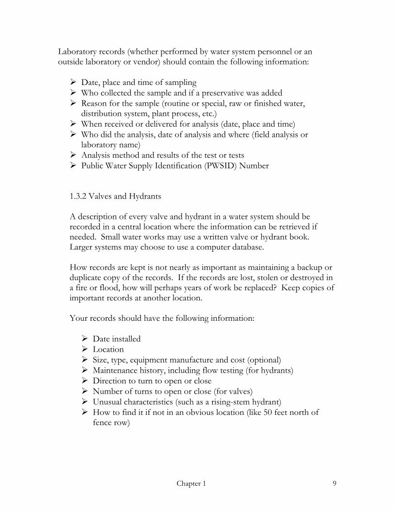
Laboratory records (whether performed by water system personnel or an outside laboratory or vendor) should contain the following information: Date, place and time of sampling Who collected the sample and if a preservative was added Reason for the sample (routine or special, raw or finished water,
distribution system, plant process, etc.) When received or delivered for analysis (date, place and time) Who did the analysis, date of analysis and where (field analysis or
laboratory name) Analysis method and results of the test or tests Public Water Supply Identification (PWSID) Number
1.3.2 Valves and Hydrants A description of every valve and hydrant in a water system should be recorded in a central location where the information can be retrieved if needed. Small water works may use a written valve or hydrant book. Larger systems may choose to use a computer database. How records are kept is not nearly as important as maintaining a backup or duplicate copy of the records. If the records are lost, stolen or destroyed in a fire or flood, how will perhaps years of work be replaced? Keep copies of important records at another location. Your records should have the following information: Date installed Location Size, type, equipment manufacture and cost (optional) Maintenance history, including flow testing (for hydrants) Direction to turn to open or close Number of turns to open or close (for valves) Unusual characteristics (such as a rising-stem hydrant) How to find it if not in an obvious location (like 50 feet north of
fence row)
Chapter 1 10
If a system does not have good valve and hydrant records, it is never too late to start a records program. Begin now and start entering information about newly-installed valves and hydrants, and start keeping maintenance and flow records. In a few years you will have accomplished an important task. Good valve and hydrant records can save countless hours of fieldwork, and are especially important during an emergency or bad weather. You may wish to contact the American Water Works Association (AWWA) or other similar organizations for more information on valve and hydrant record keeping. 1.3.3 Distribution System Maps Distribution System Maps allow the water system to be seen at a glance. The maps should show all your lines (excluding small customer service connections), storage tanks, valves and hydrants (including flush hydrants). The sizes of the lines should be noted, as well as the type of lines (ductile or cast iron, PVC, etc.) The locations of the lines should be referenced to street names, rights-of-way, permanent landmarks, etc. It is important to understand the distinction between contract plans or documents and “as-built” maps (also called “record drawings”). As-builts show what was really installed and at what actual location as compared to the original design. Almost all construction projects are completed somewhat differently than was originally planed due to unanticipated field problems and/or changes after the project plans were first drawn. Be sure that system maps accurately show what was actually installed. If you find that your current maps are different than what is in the ground, be sure to update them. It is a good idea to have copies of your system maps. This allows you to make field notes on the copies to make map updating easier. Having extra copies of the maps also makes it easier for the people who need them to get them during an emergency.
Chapter 1 11
1.3.4 Maintenance Logs Almost every piece of equipment in a water system needs to be maintained. It is important to keep maintenance logs for all equipment, including the replacement of a part or whole item. The needs for maintenance include extending the life of equipment, lowering the operating costs and scheduling repairs or replacements at times convenient to the operator. Good maintenance helps make a system more reliable during periods of high water demand. Maintenance logs can provide records that show required maintenance activities have been performed. This can be useful in resolving warranty claims. These same records can help you in budgeting especially if you allocate funds between different operating divisions such as treatment plant, distribution system, etc. Even the smallest system can benefit from maintenance logs. These records can be used to help predict when equipment may fail. For example, if your log shows that a seal in a pump is needing replacement more and more frequently, you will know that it is probably in need of rebuilding or replacement. You can then schedule the maintenance rather than dealing with an unexpected outage.
Chapter 1 12
Here is a sample maintenance log form that you can change to meet your needs:
North Normal, Indiana Water Works Maintenance Log
Date: 5/6/99 Equipment: High service pump 2 Work performed: Checked amps on both legs #1 16.1, #2 15.8 Re-packed lower seal Notes: Need more packing material Completed by: Bob Martin _____________________________________________________________ Date: 5/6/99 Equipment: Raw water strip chart Work performed: Refilled ink & changed paper Notes: Completed by: Bob Martin _____________________________________________________________
Date: 5/7/99 Equipment: High service pump 2
Work performed: Running hot. Amps on leg 1 OK, Leg 2 is 21.1 Notes: Needs to be scheduled to be pulled Completed by: Norm Wartz
Chapter 1 13
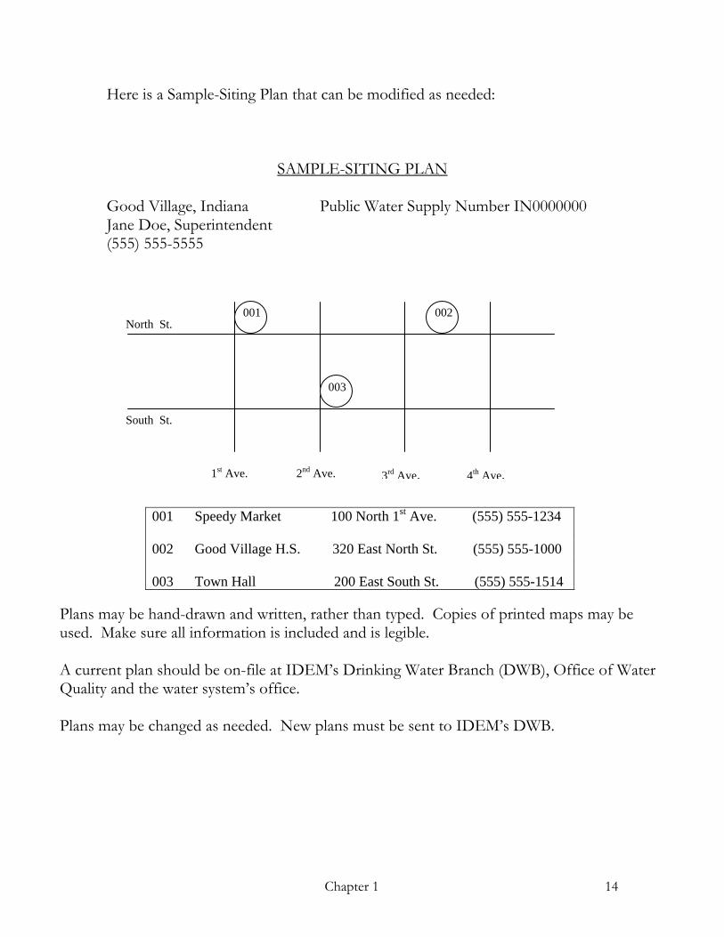
1.3.5 Manuals Manuals are necessary for the operation of water systems. They will help you operate and maintain equipment and assist you in obtaining replacement parts. A manual for the installation, operation and maintenance of equipment should be supplied to you whenever a new piece of equipment is installed or sold to you. Many manuals include a parts list, suggested spare parts inventory and distributor and repair contractor contacts. If the equipment is complex and was installed by a contractor, a drawing of the installation should be made available to you. Be sure that the drawing is an “as-built” or “record drawing,” that depicts what was actually installed (as opposed to what was specified). Manuals should be kept in a location where people who may need them can reference them. It is a good idea to make copies of all or parts of manuals that are needed in the field to prevent loss of or damage to the originals, which may be hard to replace. If manuals are missing that might be needed in the future, consider contacting the manufacturer or sales representative for replacements before the manual is needed. This can often be accomplished at little or no cost. 1.3.6 Sample-Site Plans Total Coliform samples must be collected according to an IDEM-approved sample-siting plan. The sites should be carefully chosen so as to allow for the collection of water samples that are representative of the water in the distribution system. Dedicated sampling taps are preferred. Outside faucets, which may be hard to disinfect, and taps at dead end lines where the water may be old and not representative of the distribution system water, should not be used. Sample-siting plans should include a map with each site identified by a three digit number. A list showing the site description, address and telephone number (if available) that is referenced to the site numbers should be included in the plan. The number of sites depends on the size of the water system.
Chapter 1 14
North St.
Here is a Sample-Siting Plan that can be modified as needed:
SAMPLE-SITING PLAN Good Village, Indiana Public Water Supply Number IN0000000 Jane Doe, Superintendent (555) 555-5555
001 Speedy Market 100 North 1st Ave. (555) 555-1234 002 Good Village H.S. 320 East North St. (555) 555-1000 003 Town Hall 200 East South St. (555) 555-1514
South St.
1st Ave. 3rd Ave.2nd Ave. 4th Ave.
001
003
002
Plans may be hand-drawn and written, rather than typed. Copies of printed maps may be used. Make sure all information is included and is legible. A current plan should be on-file at IDEM’s Drinking Water Branch (DWB), Office of Water Quality and the water system’s office. Plans may be changed as needed. New plans must be sent to IDEM’s DWB.
Chapter 2 15
Chapter 2
Key to the successful operation and management of a public water system is the knowledge of individuals about their job responsibilities. Knowledge is a tool just as are wrenches and computers. Each individual must be given the proper tools to get the job done right.
2.1 Management of public water systems Management of a water supply involves five elements:
Organizing Planning Financing Maintaining Adhering to the laws, regulations and practices of the profession
2.1.1 Public water systems usually are organized as municipally- or privately-owned. 2.1.1.1 Municipally-0wned A municipally-owned water system is a public water system that is owned and operated by a local government or urban political unit with corporate status. The property owners or voters are substituted for the stockholder of a privately owned system. Examples would be water systems owned by cities and towns. Normally the mayor or water board is the policy-making body.
Operation and Management of a Public Water Supply
Chapter 2 16
2.1.1.2 Privately-owned One or more private investors own a private water system. This could be an individual, partnership, corporation, or other qualified entity, with the financial backing provided by one or more investors. Control over operations may be under the direct supervision of the owner or accomplished through an elected board of directors and its directives carried out by the president. These organizations may be for-profit or not-for-profit. 2.1.2 Planning Organization planning is the development of a structure that will enable people to work together effectively to accomplish their goals and objectives. This structure must be designed so that daily needs are met along with future needs. This plan must be periodically evaluated to make sure it is still meeting the needs and objectives. Periodic changes probably will be needed. 2.1.3 Customer Relations Customer relations are the means to promote good will and understanding between the water supplier and its customers, thereby developing a favorable public image.
The employees have the greatest influence on the water supplier’s public image. Their ability to supply safe water in both quality and quantity at a reasonable pressure, along with courteous and intelligent handling of customer requests and complaints, will greatly affect this image. Remember, a complaint is an opportunity to improve your image if handled correctly and in a professional manner. Common concerns of customers are water quality (taste, odors and turbidity), low or high pressure, all types of water leaks and high water bills.
2.1.3.1 Protection of Public Health The most important responsibility of a water supplier to protect the public health by providing water that is free of disease and toxic chemicals. All the laws and regulations require this but it is still up to the water supplier to make sure it happens. There are many tools at the water supplier’s disposal to accomplish this.
Chapter 2 17
First, there is a Wellhead Protection regulation to protect the source of water. Second, there are a multitude of tests to verify the quality of the raw and finished water. Then there are many different types of water treatment that can purify the water to improve the quality so that it can meet the regulations, laws and needs of the customer. Third, disinfection is critical in meeting safe drinking water. Chlorine has been for many years the main chemical to make sure drinking water is free of any pathogenic bacteria by killing these bacteria. Chlorine has also allowed the water supplier to carry a chlorine residual in the water distribution system to kill any other bacteria that might enter the distribution system later. There are other disinfection chemicals and water treatment processes that are available to accomplish the same result. Every water system is different and the water supplier will need to choose the process that works best for them. Fourth, cross connection (backflow) control helps prevent possible contamination from customer piping systems. Cross connection control is typically implemented with approved check valve assemblies that do not allow water to flow backwards from the customer’s plumbing into the public water supply. 2.2 Finance Every water system requires proper financing to be a viable operation. Citizens of a community or private investors may provide initial financing. To continue to operate, however, a system must be supported by an adequate rate structure that meets current and future needs. 2.2.1 Rates In providing adequate water service to its customers, every water utility must receive sufficient total revenue to ensure proper operations and maintenance (O&M), development and perpetuation of the system, and preservation of the utility’s financial integrity. Nearly all of total revenue requirements for most utilities are met from revenue derived from selling water to their customers. Other revenue not derived from the sale of water may come from a variety of sources such as rentals, merchandising, and providing services to other utilities or entities, and capacity or impact fees.
Chapter 2 18
It is important to ensure that a rate or rate structure is consistent with applicable local, state, and federal laws before it is implemented. The implementation of a rate structure that may be prohibited by or is inconsistent with laws or statutes puts the utility at unnecessary risk. All relevant laws that could affect the use of a particular rate alternative should be evaluated by the utility. Laws and regulations may be significantly different for governmental water utilities than for investor-owned water utilities. They may, however, be quite similar for government-owned and investor-owned utilities regulated by the same public service commission. Water utilities are typically required to submit their proposed rate tariffs to state regulatory agencies for review and approval. In most cases, the laws, regulations, and procedures are usually well defined for the utility to comply with and follow in identifying revenue requirements, allocating costs, and designing rates. 2.2.2 Rate Structures Financing and rate setting can be very complex and critical to a water utility. Therefore, a listing of the different types of rates that could be used is as follows:
- Lifeline Rates & Low Income Discounts - Inverted Block Rate - Declining Block Rate - Uniform Volume Rates - Economic Development Rates - Off Peak Rates - Seasonal Rates - Negotiated Contractual Rates - Marginal-Cost Pricing - Indexing or Indexed Rates - Rate Schedules by Customer Class
Chapter 2 19
2.2.3 Rate Approvals Once the rate structure has been determined by the local governing body, normally through a rate ordinance, a filing of the ordinance with the rate tariff will need to be filed with the State Regulatory Commission. This will only be done if the water utility comes under the Regulatory jurisdiction. Some utilities have opted out of this jurisdiction and rates are approved at the local level. After the Rate Ordinance has been filed with the Regulatory Agency, there may be a number procedural steps that will take place prior to the approval and initiation of the rates. Basic procedural steps that may take place are:
- The initial filing of rate and charges - Prefiled testimony of the petitioner – - - Superintendent - - Engineer - - Rate Consultant/Accountant - Initial Public hearings - Discovery and information gathering by the Public - Settlement Agreements between Petitioner and Public - Final Hearing - Approval - Initiation Note, these are basic steps to give the water utility a general understanding of what may be required when going through the regulatory commission. Further, if a Bond Issue is required, then there will be additional steps the Water Utility and the Regulatory Commission will need in order to finalize the rates for approval.
2.3.1 Operator Responsibilities A certified operator is morally and legally responsible to provide a safe water supply used for human consumption. The certified operator must remember the importance of water to the community and produce it in the most efficient, reliable and economical manner.
Chapter 2 20
The operator deals with the water system every day and is responsible for giving the best service possible at all times. You are the first contact the public will make. You must not only know and apply critical water distribution techniques, but you must conduct yourself in such a manner that the public is confident that the service is performed properly. Almost everyone in a community takes the water for granted and expects safe and sufficient quantities and adequate pressure. This is largely because of the efforts of the professional water operator. Most often water is the least expensive vital resource available. Safeguarding the quality of water is becoming increasingly important. Your daily activities can greatly influence the quality of the water that is delivered. Requirements will need to be met now and in the future as new rules are constantly being added. An operator must always be alert for possible events that could contaminate the water. Cross-connection and backflow situations are always a concern. An operator is a vital person to provide “WATER FOR PEOPLE.” 2.3.3 Groundwater Supplies Water supply for Public Water Systems in Indiana is about evenly divided between ground water and surface water in terms of gallons pumped, but there are many more ground water systems than surface water systems. Obviously, ground water systems on average are smaller in capacity than surface water systems. Any groundwater supply with a withdrawal capacity of more than 100,000 gallons per day (GPD) must be registered as a Significant Water Withdrawal Facility with the Indiana Department of Natural Resources. The total developed groundwater source capacity should generally equal or exceed the designed maximum day demand and equal or exceed the designed average day demand with the largest producing well out of service.
Chapter 2 21
Schools, correctional facilities, health care facilities, and agricultural labor camps, regardless of pumping capacity, must have at a backup water well(s) to meet the “largest producing well out of service” requirement, i.e., a minimum of at least two wells. 2.3.3.1 Well Disinfection Current design and construction rules for Public Water Supplies (327 IAC 8-3.4-24) require the following disinfection procedures, which shall be performed with calcium hypochlorite or sodium hypochlorite:
Gravel installed in a new production well for gravel pack must be chlorinated by use of hypochlorite prior to installation in a well at a rate that will produce a liquid concentration of at least 50 milligrams per liter (mg/L) as the gravel is installed. As an alternative, chlorine shall be added to the well and circulated until a chlorine concentration of not less than 50 mg/L in the entire volume of fluid in the well bore is achieved.
Permanent equipment and material used in a production well shall be
chlorinated prior to installation by spraying exposed areas with a solution containing a chlorine residual of not less than 200 mg/L.
A new or modified well proposed to be a production well should be chlorinated according to one of the following methods:
1. The water in the well casing shall be treated for disinfection to create a minimum chlorine residual of 100 mg/L in the entire volume of water in the casing, well screen, and rock hole, if present. The well must be chlorinated using the amount of chemical compound in the table below, and the well must be surged at least three times following chlorination. The chlorinated water must then remain in the well at least 12 hours following the surging activity.
2. The water in the well casing shall be treated for disinfection to
create a minimum chlorine residual of 50 mg/L in the entire volume of water in the casing, well screen, and rock hole, if present.
Chapter 2 22
3. The well shall be chlorinated using the compound requirements in
the table below, and the well must be surged at least three times following chlorination. The chlorinated water must then remain in the well casing at least 24 hours following the surging activity.
Amount of Chemical Compound Well-Hole or Volume per 100 Feet Calcium Hypochlorite* Sodium Hypochlorite** Well Casing of Water Depth (65 percent available (12 percent trade avail- Diameter (in.) (Gallons) Chlorine) able Chlorine***) 5 106.09 1.1 oz 5.65 fl oz 6 146.9 1.5 oz 7.8 fl oz 8 261.1 2.7 oz 13.9 fl oz 10 408.0 4.2 oz 1.4 pt 12 587.5 6.0 oz 2.0 pt 16 1,044.0 10.7 oz 3.5 pt 20 1,632.0 1 lb 1 oz 0.7 gal 24 2,350.0 1 lb 8 oz 1.0 gal 30 3,672.0 2 lb 6 oz 1.5 gal 36 5,287.0 3 lb 6 oz 2.2 gal 48 9,400.0 6 lb 1 oz 3.9 gal 60 11,690.0 9 lb 7 oz 6.1 gal
Notes: * Quantities of Ca (OCl)2 based on 65 percent available chlorine by dry weight (16 oz = 1 lb). ** Quantities of NaOCl based on 12 trade per cent available chlorine by U.S. liquid measure (1 gal = 4 qt = 8 pt = 128 fl oz). *** Trade percent is a term used by chlorine manufacturers; trade percent x 10 = grams of available chlorine in 1 liter of solution.
After disinfection is accomplished as indicated above, a new or modified public water supply system production well, including flowing wells, shall be sampled for the presence of coliform at least twice, with sampling done no less than 24 hours apart. The sample shall be examined by a laboratory certified by the Indiana State Department of Health. If the presence of coliform is indicated by the sample results, the disinfection of the well shall be repeated. Disposal of chlorinated water from well disinfection shall be to a sanitary sewer with the approval of the local sewer authority, or to a location other than a sanitary sewer in accordance with local, state and federal regulations.
Chapter 2 23
2.3.3.2 Well Maintenance Maintenance of water wells can be summarized very simply: Take care of the well and pump equipment before they become unreliable or inoperable. Groundwater chemistry and biology issues, physical issues and pumping/over- pumping issues all affect the need for well maintenance. Biological activity reaction tests (BARTs) can give an indication of biological fouling, including iron bacteria, slime forming bacteria and sulfate reducing bacterial. Particulate matter, such as sand, also is an indication of problems. Physical and biological changes occur around the well as a result of the increased movement of water toward the well. These changes eventually will cause plugging and clogging of the well, resulting in decreased production and/or lowered pumping water levels in the well. Static and pumping water levels should be measured at least every six months, with one set of the readings to be made during the peak-pumping season. Maintenance test pumping, including readings of static and pumping water levels and determination of specific capacity (SC) should be accomplished at least every two years for all Community Water Systems, Noncommunity Nontransient systems and susceptible populations, which includes schools, correctional facilities, health care facilities and agricultural labor camps. Noncommunity Nontransient systems should have maintenance test pumping at least every four years. (Specific capacity is calculated by dividing the production of the well in gallons per minute [GPM] by the feet of drawdown between the static water level and the pumping water level. Water levels need to stabilize before measurements are made. The GPM should be the normal production rate of the well and pumping equipment.) The SC needs to be recorded and plotted against time. Normally, the SC holds steady during the early stages of a well’s life, followed by a period of slow decline, and finally a sharp drop-off as the flow paths around the well close off. But there are many exceptions to this pattern. For example, it is not uncommon in limestone wells to see the SC increase as new flow paths develop. In determining the change in SC, the percentage change, not the absolute numbers, is important.
Chapter 2 24
Recent research published by the American Water Works Association emphasizes the importance of knowing the SC. If the SC drops too far below the original SC, the full capacity will likely not be recovered with well rehabilitation. AWWA published SC guidelines can be summarized as follows:
Full recovery of capacity is probable with normal rehabilitation work if the current SC is greater than 85 percent of the original SC. Full recovery of capacity may be possible, but more extensive (and expensive) rehabilitation work will be needed if the current SC is less than 85 percent of the original SC but greater than 60 percent of the original SC. Full recovery of capacity is unlikely if the current SC is less than 60 percent of the original SC. The well may be unsalvageable if the SC drops below 40 percent of the original SC.
It is important that rehabilitation work start before the well’s SC falls below 85 percent of the original value, according to the AWWA publication. Doing the rehabilitation work at this point increases the chance of success and reduces the amount of work (and cost) necessary. This is a critical factor if the capacity is to be recovered repeatedly in a cost-effective manner. 2.3.4 Surface Water Surface water is the major source for public water supply systems. This is because large cities draw most of their water from surface reservoirs. About three out of every four people in the US drink water that originated from surface water sources, so it is important for you to have a thorough understanding of the factors that influence surface water flows. Surface waters come from two sources:
- Precipitation - Ground water
Chapter 2 25
When rainfall reaches the ground it either infiltrates the soil, evaporates into the air, or runs off as surface water. But rainfall is not the only form of precipitation that results in surface water runoff. Snow, which may remain on the ground for many months, eventually melts and also contributes to surface water runoff. In portions of the western US, melting snow produces the major part of the annual runoff. If rainfall were the only source of surface waters, then all streams and rivers would dry up shortly after a rain; however, many streams and rivers flow throughout the year. This is due in part to snowmelt and in part to ground water that enters streams and rivers from springs and seeps. Just as ground water can give up water to a stream, streams give up a portion of their flows to recharge ground waters. There are a variety of factors that affect surface runoff. Perhaps the most significant are:
- Rainfall intensity - Duration of rainfall - Soil composition - Soil moisture - Slope of the ground - Vegetation covering the ground - Man-made influences
Slow, gentle rainfalls usually produce very little runoff. There is plenty of time for the rain to soak into (infiltrate) the soil. However, as rainfall intensity increases, the surface of the soil becomes saturated. Since a saturated soil can hold no more water, further rainfall builds up on the surface and begins to run off, creating surface water flow. Man-made influences have a decided effect on surface water runoff. Dams control it; channels, canals, and ditches divert it; and streets and other paved areas increase it. After surface water runoff has been produced, it flows in the path of least resistance. It begins to form rivulets, which will often then flow into brooks, creeks, and rivers. Each rivulet, brook, creek, and stream receives water from an area of land surface that slopes down toward one primary watercourse. This drainage area is known as a watershed or drainage basin.
Chapter 2 26
Within a watershed, there are two types of surface waters: (1) Watercourses, and (2) Water Bodies. Watercourses convey surface waters from higher elevations to lower elevations. Typical natural and man-made watercourses include: Natural Man-Made
Brooks Ditches Creeks Channels Streams Canals Rivers Aqueducts Natural watercourses may flow continuously or only occasionally. Continuously flowing streams are called perennial streams. These streams are supplied both by surface runoff and by springs and ground-water seepage. Streams flowing only occasionally are called ephemeral streams. Ephemeral streams usually flow only during and shortly after a rain, and are supplied only by surface runoff. Man-made watercourses carry water only when man intentionally diverts water to them. A water body is a water-storage basin. It can be a natural basin such as a pond or lake, or a man-made basin such as a reservoir. Man-made water bodies are built to serve some specific water need. These bodies range from basins for watering stock to massive reservoirs that store water for municipal and recreational use. 2.3.4.1 Reservoirs The name “reservoir” is ordinarily applied to a basin designed to store water during periods in which the stream flow is greater than the demand and to deliver water during periods when the reverse condition occurs. Building a dam in a natural valley or canyon usually forms reservoirs, thus developing an artificial lake or pond from which water may be drawn at will to supply the required demand.
Chapter 2 27
Safety, cost, need for water, and the number of sites available are among the factors that will decide the feasibility of any particular site. The selection of a site for an impounding reservoir is predicated upon the fact that the yield of the stream will serve the intended purpose. The determination of the yield involves the complicated problems of storage, regulation and sanitary features of reservoir sites, their maintenance and their use as recreational centers. All of these need to be investigated. Since the water quality of reservoirs is dependent upon the runoff from surrounding areas (the watershed), it is important to realize that it is the responsibility of the administrative authority to manage the area in the watershed to assure a safe and adequate water supply. The extent of the area and the responsibility of the administrative authority are governed by federal and state statute. Any question regarding the management of the watershed and/or water quality should be directed to the appropriate governmental authority. 2.3.4.2 Outlet/Diversion Controls Outlet structures are usually provided in impounding reservoirs to control the release of stored water. In waterworks practice, they are usually considered as intakes. It is frequently necessary to provide outlet works for spillway purposes or for emptying the reservoir for repairs, destruction of plant growth, desilting, etc., or for supplying water to prior rights or riparian (land owner) interest on the stream below the dam. Design considerations include location, capacity, structural features, and safety. The elevation of the outlet works depends on the purpose of the works and the type of dam. If this purpose is to drain the reservoirs, the outlet must be located at or near the bottom. This is also the case if the structure is to be used for stream control during construction. A position near the base of the earth dam is preferable on account of increased safety from the dangers of percolation and settlement. Safety implies the exercise of sound engineering judgment and ability to assure the adequacy of the structure in the performance of the functions for which it is built.
Chapter 2 28
2.3.5 Clearwells Clearwells are usually located at the end of a treatment train or at the end of a well or well system. This configuration is used for contact time when chemical treatment additives are used. These storage structures have limited use as storage reservoirs due to their location. Since they are typically located at the end of the well system or of the treatment process, they have limited availability for reliable distribution system supply in case of emergencies. Clearwell storage usually must be pumped and would require standby power to be a reliable resource in case of an emergency. The most effective use of clearwells is as a contact basin utilized for treatment purposes. The added storage or reserve capability of clearwells are an advantage for operators that need time for maintenance of equipment or structures, but this is not their intended use. Utilities should not rely on clearwell storage as their only means of reserve for the distribution system. The rated capacity of the process and the contact time necessary to achieve the results of the process are the main focus of clearwell design. Since the purpose of the clearwell is for contact time, the design must assure that short-circuiting does not occur. Adequate mixing and contact time can be achieved by baffling and good placement of the chemical injection points. Provisions for overflowing and venting the clearwell are important. When designed properly they should exclude the entrance of foreign material and be of adequate size to remove water (waste) in excess of the filling rate. The overflow pipe and/or vent should eliminate insects from entering the clearwell. Vents and overflow pipes should not be susceptible to freezing. Clearwells should be easily accessible for inspections and cleaning. The design should incorporate means of evacuating accumulations of sludge or settled solids. This can be achieved by the means of sump pumps or areas to gather material washed from the walls and floor. Considerations must be given to the type of concrete and materials used in construction. The clearwell environment can be aggressive due to the addition of chemicals and the water quality. High sulfide containing water can deteriorate concrete and high chemical residuals can corrode metals that may be in the clearwell or in structures above them. Access to clearwells must be secure from vandals and acts of terrorists by employing locks, fences, alarms and/or other security devices or programs.
Chapter 2 29
Optimum chlorine levels should be maintained to assure that all treatment requirements are met. This is equally true when adding other chemicals. The placement of chemicals in the clearwell should be evaluated for their cause and effect before they are added. Just adding treatment aids at the beginning and/or end of the clearwell does not assure that the optimum results will occur. Retention time, water quality and distribution system residuals will dictate how and when treatment chemicals are added to the clearwell process. 2.3.6 Filtration Filtration is the most common form of water treatment for Public Water Systems in Indiana, and it usually is preceded by aeration or some form of oxidation prior to the filtration. Various forms and configurations of aerators and filters are used throughout the State, but they most commonly fall into the classes of pressure filters and gravity filters. 2.3.6.1 Pressure Filters The most common use of pressure filters is for iron and manganese removal. Pressure filters shall not be used in the filtration of surface water, polluted waters or following lime-soda softening. The rate of filtration shall not exceed three gallons per minute per square foot of filter area, except where in-plant testing, as approved by IDEM, has demonstrated satisfactory results at higher rates. Filters shall be designed to provide for loss of head gauges on the inlet and outlet pipes of each filter, an easily readable meter or flow indicator on each batter of filters and a flow indicator are recommended for each filtering unit. A minimum of two filter units or cells shall be provided. Where only two units are provided, each shall be capable of meeting the plant design capacity, which normally is the projected maximum daily demand at the approved filtration rate. Where more than two filter units are provided, the filters shall be capable of meeting the plant design capacity at the approved filtration rate with one filter removed from service.
Chapter 2 30
Minimum sidewall shell height shall be 5’0”. A reduction in sidewall height is acceptable where proprietary bottoms permit reduction of the media depth. Backwash flow indicators and controls that are easily readable shall be provided, along with an air release valve on the highest point of each filter. An accessible manhole to facilitate inspection and repair of the filter tank, means to observe the backwash wastewater and construction to prevent cross-connection shall be provided. Media for filters shall be clean silica sand or other natural or synthetic media approved by IDEM. The media shall have a total depth of not less than 24” and generally not more than 30”, and the effective size range of the smallest material shall be no greater than 0.45 mm to 0.55 mm, with a uniformity coefficient of the smallest material not greater than 1.65. There shall be a minimum of 12” of media with an effective size range no greater than 0.45 mm to 0.55 mm, and a specific gravity greater than other filtering materials within the filter. Types of filter media:
Anthracite: Clean crushed anthracite with an effective size of 0.45 mm – 0.55 mm with a uniformity coefficient not greater than 1.65 when used alone. Anthracite with an effective size of 0.8 – 1.2 mm with a uniformity coefficient not greater than 1.85 may be utilized when used as a cap. Effective size for anthracite used as a single media on potable groundwater for iron and manganese removal only shall be a maximum of 0.8 mm. Sand: Silica sand used for filtering shall have an effective size of 0.45 mm to 0.55 mm, with a uniformity coefficient of not greater than 1.65. Granular activated carbon (GAC): Granular activated carbon media may be considered only after a pilot or full scale testing and approval of the IDEM. Larger size media can be used if specifically approved and provisions must be made for frequent replacement or regeneration if GAC is used for filtration. Torpedo Sand: A 3” layer of torpedo sand should be used as a supporting media for filter sand, and should have effective size of 0.8 mm to 2.0 mm and a uniformity coefficient not greater than 1.7.
Chapter 2 31
Gravel: Gravel, when used as the supporting media in a filter, shall consist of hard, durable, rounded silica particles and shall not include flat or elongated particles. The coarsest gravel shall be 2.5” in size when the gravel rests directly on the strainer system, and must extend above the top of the perforated laterals. Not less than four layers of gravel shall be provided in accordance with the following size and depth distribution when used with perforated laterals: Size Depth 2.5” to 1.5” 5” to 8” 1.5” to 0.75” 3” to 5” 0.75” to 0.50” 3” to 5” 0.50” to 0.18” 2” to 3” 0.18” to 0.09” 2” to 3”
Note: Reduction of gravel depth may be considered when proprietary filter bottoms are specified.
Surface or subsurface wash facilities are required except for filters used exclusively for iron or manganese removal, and may be accomplished by a system of fixed nozzles or a revolving-type apparatus. Air scouring can be considered in place of surface wash. Backwash of the filter shall be at a minimum rate of 15 gallons per minute per square foot, consistent with water temperatures and specific gravity of the filter media. A rate of 20 gallons per minute per square foot or a rate necessary to provide for a 50 percent expansion of the filter bed is recommended. A reduced rate of 10 gallons per minute per square foot may be acceptable for full depth anthracite or granular activated carbon filters. Each cell or filter shall be backwashed for at least 15 minutes, and duplicate backwash pumps or a second means of backwash water supply shall be provided. 2.3.6.2 Gravity Filters Flow rates, backwashing rates and media requirements set out in 2.3.6.1 for pressure filters also apply to gravity filters.
Chapter 2 32
2.3.11.1 Fire Hydrants The most common function of a fire hydrant is fire protection. The hydrant is the property and responsibility of the Water Department, and during an emergency it is used by the Fire Department. Fire hydrant functions such as water main flushing, construction projects, street cleaning or any purpose other than fighting a fire is outside the primary purpose for which the hydrant was installed. Such use should be controlled by the Water Department, so that the hydrant is in good working condition at all times. Hydrants should be opened and closed slowly to prevent pressure surges in the mains. These pressure surges can cause a water hammer, which in turn can cause damage to the water mains. Hydrants in your system should be flushed once a year at a minimum. Additional flushing may be required if there are treatment problems. This allows for hydrant maintenance, which helps keep everything is in good working order. Hydrant flow tests should be run on every hydrant in the system, so that fire flows are known. The information is vital for further expansion and insurance rating. Always keep records on valve locations and maintenance activities. 2.3.11.1.3 Water Meters A water meter is a device developed to measure water. Accurate water measurement is the means by which water utilities produce revenue to cover expenses, charge each customer equitably, prevent waste of water, and minimize the load on wastewater facilities. A water meter only does two things: it measures the water passing through and it records the measurement. There are a variety of styles and types of meters available. The mechanical aspects are different but the principles are the same (measure and record). The most common types of meters used in the Midwest are the positive displacement (both oscillating piston and nutating disc), multi-jet, turbo, compound, fire service, and propeller.
Chapter 2 33
Production meters (meters on wells--for ground water; raw water meters-for surface water; finished water meters--for water leaving the plant or pumping station), which will probably be propeller meters, should be tested on an annual basis. These meters should be tested in place (in their normal meter setting). It is critical that these meters be accurate. These are the most important meters in your system. With accurate production meters the utility can determine its accountability. To calculate the percentage of accountability use this formula. (Water Sold + Water Used, flushing, etc.)/Water Produced = % of Accountability The retail water meter is a critical part of the distribution system and must be monitored and maintained. The meter is the cash register of the utility. In a typical water utility 12% of the customers use 50% of the water. It’s important to review the usage patterns of these customers and to think preventive maintenance, which means establishing a meter maintenance program. Meters should be tested and repaired before there is a noticeable drop in consumption. A water meter, like any other mechanical device, will wear out. As a meter wears out it generally slows down, or operates in the customer’s favor, which means that the utility is not getting all of money that it is entitled to. It is extremely important that meters be tested for accuracy on a regular schedule. The AWWA (American Water Works Association) Manual #6 – Water Meters-Selection, Installation, Testing, and Maintenance (4th edition, last updated in 1999) lists required testing periods and test requirements for all sizes and types of water meters. One of the tables that you will find in the manual is the periodic testing requirements of the various states Public Service Commissions. Indiana’s rule is number 170 LAC 6-1. *see below* 5/8” & 3/4” 1” 1 ½” & 2” 3” and Larger
10 years 8 years 6 years 4 years These are minimum recommendations. Meter testing expense should be looked at as a form of insurance. Spending a small portion of the revenue generated by the meter to ensure that it is working properly assures that the utility receives all of the revenue to which it is entitled. The best method of determining the frequency of testing is to look at the revenue generated by the meter.
Chapter 2 34
Determine the percentage of a meter’s annual revenue that is to be set aside for meter testing and the cost of a meter test. Take the meter’s monthly revenue; multiply by the percentage of revenue set aside for meter testing. This gives a number, that when divided into the cost of a meter test, gives you the number of months between meter tests. For example, a 3” meter that has an average monthly water and sewer bill of $400.00, and 3% of revenue is set aside for testing, and the cost to test a 3” meter is $250.00. Take the average monthly bill ($400.00) multiply by the percentage of set aside (3%). $12.00 is the monthly meter testing allotment. ($400*.03 = $12.00). Take the meter testing cost ($250.00) and divide it by the monthly meter testing allotment ($12.00) $250/$12.00 = 20.8. 20.8 is the number of months, say two years, between meter accuracy tests. Displacement meters 5/8” through 2” are usually pulled (removed) from service and tested on a meter test bench. Compound and turbo meters can be pulled and tested. However, it is more efficient and more accurate to test the meters in place using a certified test meter or Pitot Rod. Testing in place is better because of the influence that the meter setting has on the meter. The configuration of the piping (elbows, tees, valves) creates turbulence in the pipe, which has an effect on the performance of the meter. A proper meter setting will have an inlet valve, test tee and outlet valve. Propeller and turbo meters require several pipe diameters of straight pipe (preferably ten) before and after the meter. This eliminates any turbulence. When a meter is tested, it will either test within required accuracy limits or it will fail. If it fails a determination must be made whether to repair or replace the meter. In most cases a meter can be repaired. In some cases a meter cannot be repaired or cost of repair would exceed 50% of the cost of a new meter. In this case the meter probably should be replaced. This is the time to determine if the meter should be replaced with same size and type of meter or if there is a meter better suited to the application. With so many types of meters available it’s important to pick the correct size and type of meter for each metering application. Choosing which type of meter to use is not as difficult as selecting the correct size. Following are the typical applications for each type of meter normally used by a water utility: Displacement meters and multi-jet meters are used for measurement of low and intermediate flows, like domestic use in residential applications. They are typically available in sizes from 5/8” through 2”.
Chapter 2 35
Turbo meters are used to measure intermediate and high flows like in a factory that uses high volumes of water, or to measure the water leaving the water plant. They are typically available in sizes from 2” through 20”. Compound Meters are used where there is the need to measure both high and low flows, like in a hotel, school, or a commercial account where both domestic use and production use need to be measured by one meter. They are typically available in sizes from 2” through 6”.
Fire Service meters are used to measure water from fire lines. There are several types of fire line meters. Some measure all of the water going through the fire line in the event of a fire; these are typically large turbo meters. Some only measure a portion of the water going through the fire line; this is called proportional metering. Some only measure low flows of water used when there isn’t a fire; these are called detector meters. There are also fire meters available that can measure both low flow domestic use and high flow fire fighting use. These are really large parallel type compound meters. They consist of a large turbo meter, a change over valve, and a 1 1/2” or 2” displacement or turbo meter to measure the domestic use.
Propeller meters are used to measure water from wells and water plants. They are used where there are no low or intermediate flows where the pumps are either on or off. They are typically available in sizes from 2” through 72”. When selecting the type of meter to use in a particular customer’s application, it is very simple if adequate and reliable usage information is available. Selecting a replacement meter for an existing facility is somewhat easier then selecting a meter for a new facility. Talk to the customer and question them as to their anticipated water needs. If the customer will only use water for domestic uses (drinking, bathing, washing, etc.) like a home, fast food restaurant, or bank, then install a displacement meter. If the customer will only use water at intermediate or high flows (filling a tank for a batch process, irrigation system, wholesale metering) then a turbo meter should be installed.
Chapter 2 36
If the customer will have multiple uses for water like a school where there are different water uses at different times of the day, from a single drinking fountain being used to dishwashers and restrooms being used during the lunch hour, then you a compound meter should be installed. When in doubt install a compound meter. An old rule of thumb for large facilities is that if someone sleeps there, and this includes apartment complexes, large office buildings and schools, install a compound meter.
Selecting the proper size of meter is more difficult then selecting the appropriate type of meter. Meter size generally does not equal service size. To determine the correct size of meter a fixture evaluation must be performed. To do this, use AWWA Manual 22 – Sizing Water Service Lines and Meters. To perform a fixture evaluation, the number and types of water using devices are inventoried (counted and recorded). This means that every sink, shower, toilet, hose bib, washing machine, etc. is counted. The gallons per minute needed for lines supplying make up water, irrigation sprinkling zones and manufacturing process must be determined, along with the water pressure at the meter. With this information and using the simple procedures in the M22, the customer’s peak demand in gallons per minute can be estimated and the size of meter determined. In addition, after a facility has been inventoried, you will have the information you need to pick the type of meter that best fits the application. There are several different types of registers available today to fit any application. Meters are provided with direct read registers unless some type of remote reading system is ordered. A direct read register has an odometer that the meter reader will record to get the meter reading. Registers are available in the Midwest to measure in Gallons or Cubic Feet. Different sizes of meters take different registers. It is important that they not be mixed up. Just because it will fit doesn’t mean it will work. Each size meter has a specific register; the internal gearing is designed to properly display the amount of water used for that particular size, brand and type of meter. The same is true of remote systems. Do not interchange remotes. Each size of meter has a designated remote with the appropriate number of fixed (non-moving) zeros.
Chapter 2 37
It is important that the billing office have an accurate record of the number of fixed zeros on each water meter’s register or remote. If a customer is billed for 10,000 gallons of water when they actually used 100,000 gallons, the customer is getting 90% of their water for free. If you are billing your customer for 100,000 gallons of water while they actually used 10,000 gallons then they are being billed 10 times too much. A zero is only a zero, unless it’s on the end of a meter reading. Then it is a multiplier! 2.3.11.1.5 System Flushing Water main flushing is performed to maintain water quality in the distribution system. Water quality is the number one goal of every water operator. If a distribution system cannot deliver high quality water or if there are problems in specific areas (i.e., discolored water, turbidity, high iron, etc., a water main flushing program can help alleviate those problems. A water utility is a business, and like any business, the primary goal is to deliver a high quality product effectively and efficiently. To determine a distribution system’s functionality and ensure quality water is properly delivered, is not something that can be done overnight. It takes time, effort and desire. A water utility needs to follow a few basic, proven steps. These steps will allow any water utility to determine their distribution system’s ability to provide high quality water on demand. Prior to performing any type of flushing it is important to be aware of some of the hazards associated with flushing. System personnel need to be aware of where the flushing water will drain. In areas without curb and gutter, someone’s house or garage can be easily flooded. Be aware of traffic and properly control it. Most importantly be aware of children. A flowing hydrant attracts children faster then an ice cream truck. The proper tools are always needed: a good quality hydrant wrench that won’t slip on the hydrant-operating nut, a Pitot Gauge to measure the pressure of the flowing water, a hydrant diffuser to dissipate the force of the flowing water and a hydrant port adapter with a gate valve to attach to the hydrant port prior to opening the hydrant. Diffusers that have a built in Pitot Gauge or diffusers that have a slot to insert the Pitot Gauge can be purchased from many suppliers.
Chapter 2 38
Prior to flushing the hydrant adapter will need to be installed with the 2 ½” gate valve to the hydrant port. The use of this valve is strongly recommended. By using the valve to control the water flow from the hydrant, the possibility of creating a water hammer by opening or closing the hydrant too fast may be alleviated. The hydrant must be opened completely or water will escape through the hydrant’s weep hole. If water is leaking out of the weep hole, the ground around the hydrant will become saturated with water, thus not allowing the hydrant to drain properly, and the saturated ground can make the hydrant unstable if it is left leaking long enough. Therefore, if you need to open the hydrant completely to block the weep hole, then the only way to control the water flow from the hydrant is with the gate valve. Another equally important reason to use the gate valve is that in the event that a rock or something else flows into the hydrant during flushing, the flow of water can be stopped. System personnel should be aware of how they stand while opening the hydrant. Back injuries are very common as a result of not standing properly and/or twisting the upper body while pulling on the hydrant wrench. Place the hydrant wrench on the hydrant and position the body so that the operator is standing parallel to the wrench. Grip the wrench with both hands and pull. If the hydrant operates smoothly so that the wrench can be turned with one hand, then the operator may step to the side and turn the wrench around the hydrant. If both hands are needed, pulling toward the operator to turn the hydrant wrench, then the operator should back up a step and pull the wrench toward the operator. Repeat this process backing around the hydrant until the hydrant is open or it starts to turn easily. This same procedure should be used to close the hydrant. When flushing is finished, the hydrant must be completely closed. Close it snuggly then back it open ¼ turn. This prevents the hydrant stem from seizing. Once the hydrant is closed, make sure that the hydrant is draining properly. If the hydrant stands full of water it will freeze and break. To make sure that the hydrant is draining, hold a hand over the hydrant port, sealing it. While the hand is sealing the port, the water draining out the hydrant weep hole creates a vacuum in the hydrant. Seal the hydrant port with the hand for 30 seconds and then slowly lift the hand. If the hydrant is draining, suction will be felt on the hand.
Chapter 2 39
Now is the time to remove all of the hydrant caps and grease them with non-water soluble food grade grease. A very light coating on the hydrant hose threads is all that’s needed. The hydrant stem should also be lubricated. Some hydrants have a grease fitting on the top; some have a plug that can be removed to access the fill hole for an oil reservoir. Consult your hydrant supplier for approved grease or oil. When a customer calls and complains of poor water quality (taste, odor, or color) the complaint should be logged and marked on the distribution system map. A good way to do this is to keep a system map on a bulletin board and to use different color pushpins for different types of complaints. It’s important to log all complaints so that flushing frequency can be adjusted based upon system complaints. The entire distribution system does not need to be flushed each time a complaint is called in. Generally once a year is sufficient depending on your system water quality, but some parts of the distribution system may need to be flushed more frequently. It’s possible that a dead end line may need to be flushed once a month. When flushing in response to a customer complaint, perform a slow or low velocity flush. Flush enough water to clear the suspended particles, but at a low enough velocity to not stir up the particles that have settled out. Attach the control valve to one of the 2 ½” ports of the hydrant so that the flow can be throttled. With this type of flushing, a small segment of the distribution system will be flushed. This is a temporary fix. The same low flow characteristics that created the original customer complaint will over time cause the poor water quality to return. By tracking these complaints the frequency of flushing can be determined. If flushing a dead-end every month eliminates all complaints, try flushing every two months. If there are no complaints, try every three months. The idea is to flush only as often as necessary. Flush often enough to keep the water quality good and yet be conservative enough as not to waste water. When performing scheduled system flushing, plan each day’s flushing sequence, starting at the source of supply or previously cleaned mains and working out into the distribution system. Flush from larger mains to smaller mains.
Chapter 2 40
Once the flushing plan is established, it is time to notify the public and make them aware of what is being done, when it will be done and the areas that will be affected. There are two types of scheduled system flushings that you can perform. Both have their advantages and disadvantages. The first is multi-directional (normal) flushing where valves are not operated. Hydrants are flowed starting at the source of supply. One hydrant is opened and another closed, always having a hydrant flowing. The disadvantage to this type of flushing is that, unless a dead end is being flushed, when a hydrant is flowed the water comes from both directions of the water main. Twice as much water may be needed to achieve the necessary velocity to clean the water main. The advantage is that valves need not be operated and artificial dead ends created. This is the least desirable method of flushing in regard to conservation. The preferred method of flushing is unidirectional flushing. The disadvantage is that you have to have performed a main line valve-exercising program to ensure that valves work properly and that the distribution system map shows the correct placement of the valves. The advantage is that it conserves water. Valves are closed to create artificial dead ends. The necessary main cleaning velocity is obtained while flushing less water. Generally, large supply mains will not have as much sediment as small mains. The velocity of the water moving through large mains is sufficient to keep all particles suspended. As the water enters the mains where there is less flow and a lower velocity the particles will settle out. This settling will occur at the tees where the low velocity mains tie into the high velocity mains. To clean the mains the water should be moving in the main at a minimum speed of 2.5 feet per second, 5 feet per second is optimal. The hydrant must be flowed long enough to thoroughly flush the main and to completely displace all of the water in that segment of main. It is very important to keep a residual pressure gauge on another hydrant of the main being flushed to make sure that during the flushing of that particular length of main, the residual pressure does not drop below 20 p.s.i. If it does, it could mean that there is a partially closed valve, or the main may be closing up with encrusted scales.
Chapter 2 41
To determine if the required flushing velocity has been achieved, the following chart that give examples for 500-foot sections of water main can be used:
MINIMUM FLUSHING VELOCITY @ 2.5 fps. PIPE
SIZE PIPE RADIUS
PIPE AREA
VELOCITY HYD PORTS
FLUSH TIME
AMT. FLUSHED
Diameter in Ft. in Sq. Ft. 2.5 FPS 2-1/2" Diameter
Minutes Gallons
4" 0.1666 0.08715 97gpm 1 port 3.33 min. 323.1 gals. 6" 0.25 0.19625 220 gpm 1 port 3.33 min. 732.6 gals. 8" 0.3333 0.3488191 390 gpm 1 port 3.33 min. 1298.7 gals. 10" 0.41666 0.5451214 610 gpm 1 port 3.33 min. 2031.3 gals. 12" 0.5 0.785 880 gpm * 2 ports 3.33 min. 2930.4 gals. 16" 0.6666 1.39527 1565.5 gpm * 2-4"
ports 3.33 min. 5213.1 gals.
RECOMMENDED FLUSHING VELOCITY @ 5 fps PIPE
SIZE PIPE RADIUS
PIPE AREA
VELOCITY HYD PORTS
FLUSH TIME
AMT. FLUSHED
Diameter in Ft. in Sq. Ft. 5 FPS 2-1/2" Diameter
Minutes Gallons
4" 0.1666 0.08715 194 gpm 1 port 1.66 min. 323.1 gals. 6" 0.25 0.19625 440 gpm 1 port 1.66 min. 732.6 gals. 8" 0.3333 0.3488191 780 gpm 1 port 1.66 min. 1298.7 gals. 10" 0.41666 0.5451214 1220 gpm * 2 ports 1.66 min. 2031.3 gals. 12" 0.5 0.785 1760 gpm * 2 ports 1.66 min. 2930.4 gals. 16" 0.6666 1.39527 3131 gpm * 2- 4"
ports 1.66 min. 5213.1 gals.
* Can use Pumper port instead of two 2-1/2" ports
Once the required flow rate (gpm) is known to achieve the required velocity that must flow out of the hydrant, system personnel need to know how much water is in the main segment that is being flushed. The following formula allows one to calculate the volume of water that needs to be flushed/flowed from the water mains:
Chapter 2 42
Unidirectional Flushing Math This is the math formula for figuring the volume (in cu. ft.) of what is in the water main; as follows: V = A x L
V = Volume in cu. ft. A = (area in square ft.) = � x R (squared) R = radius of main (in feet) � = 3.14 L = Length of main (in feet) Example: 500 ft. of 12" main has how many gallons of water in it? V= A x L V (cu. ft..) = [3.14 x (.5ft x .5ft.)] x 500 ft. V (cu. ft..)= [3.14 x (.25 sq. ft.)] x 500 ft. V (cu. ft..)= .785 sq. ft. x 500 ft. V (cu. ft..)= 392.5 Cu. Ft.. 1 cubic foot of water = 7.48 gallons of water. V (gallons) = 392.5 cu. ft. x 7.48 gallons/cu. ft.. V (gallons) = 2935.9 gallons *Please note that the radius of the main needs to be measured in feet, not in inches. Therefore, 500 feet of 12" main has 2935.9 gallons of water in it. To flush this length of main @ 2.5 feet per second, divide 500 feet by 2.5 feet per second to get minimum time of flush (in seconds). Divide by 60 to get time in minutes. 500 feet divided by 2.5 feet per second = 200 seconds or 3.33 minutes.
2935.9 gallons divided by 3.33 minutes = 881.6 gallons per minute (for the flow rate) to get the minimum flushing velocity for the 12" main.
Chapter 2 43
As long as the flow gauge on the diffuser is showing this flow rate or higher for the 12" main, everything should be OK. A better flow rate would be 5 feet per second or 1763.3 gallons per minute. In some cases, the flow rate may need to be as high as 7.5 feet per second or 2644.8 gallons per minute to create enough turbulence in the main to scour it clean. The objective is to completely displace the total amount of water in the main and continue flushing until the water is clear. This will help conserve the amount of water being used during the flushing program but also will allow for a complete flush. The flushing events for each segment of main need to be recorded. Log everything such as each valve that is closed (or opened), each hydrant that is flowed, any hydrant deficiencies, the flow rate (gpm) and the length of time that each hydrant was flowed. The flow rate and the length of time will allow a calculation of the daily total of the water used. By logging every event, they can be repeated the next time flushing is needed. When the project is completed, review the flushing program and its techniques, problems that occurred, any hydrants that need to be repaired and what corrective actions need to be taken. An excellent reference for flushing is AWWA’s publication – Maintaining Distribution-System Water Quality. It contains procedures for handling water quality complaints, the probable cause, and the solution. 2.3.11.2 Service Line Connections Service line connections can be made when the water main is installed or years later. When a connection is made years later, a location of the water main must be determined. This can be accomplished by referring to the water map or record books. If maps and records have not been made or have been kept inaccurately, it may be necessary to locate the main by instruments. Every effort should be made when excavating, installing and restoring are undertaken that the work not inconvenience the public or homeowner. Some utilities minimize their excavation by making use of boring or trenching machines. These are useful in developed areas with paved streets, curbs, and sidewalks.
Chapter 2 44
Service lines should be protected form freezing.
1. The depth should be at least 4 feet of cover in southern Indiana and 5 feet in the central and northern part of the state.
2. Try to stay away from driveways and place the service line in the yard.
Service line material
1. Copper is the most common material for service lines 2. Plastic can also be used 3. Lead is no longer used because of health concerns 4. Brass has a very high cost 5. Galvanized has a problem with corrosion
For industrial or commercial most service lines are ductile or cast-iron. This is because of the size of the line.
When sizing a service there are two major requirements.
1. Pressure loss is the controlling factor on proper service size 2. Flow rate at point of use is important most often in the
bathroom
When installing the service line the utility must:
1. Locate all underground services 2. Make sure there is enough room to work 3. Have the correct shoring equipment 4. Make sure the thickness of the main is sufficient, if not:
A. Use a saddle B. Replace bad section of main
Multiple taps
1. Small taps to make a large one A. Example 4 ¾” taps for a 1-1/2” service
2. Make sure there is enough room between taps so the water main is not weakened, at least 10” apart
Chapter 2 45
After the service line is to the owner’s property line, a curb stop should be installed. This allows the shut off of the water service if there is a leak, or for non-payment. When the curb stop is installed, turn on the corporation stop and flush off and pressurize the line, shut off the curb stop and place a curb box and rod over the curb stop, back fill and make sure the lid is to grade. Always make record of what was done:
1. Location (address) 2. Size 3. What material was used 4. Map of curb stop
2.3.12 Safety Safety is a matter of common sense, or is it? We can all think of things that we did when we were younger that were dangerous. Any unsafe act is dangerous. Probably at the time, we didn’t realize how dangerous our unsafe act was. Not because we were stupid, but because we were ignorant. Ignorant of the potential hazards associated with our unsafe acts. Not stupid but ignorant, you might ask what’s the difference? Quite simply, ignorance is curable, stupid is forever! We can now look back and realize our mistakes and/or the risks that we took. Keep this in mind and ask yourself, what actions do we take today that are unsafe. Without proper safety training we are sometimes ignorant of the dangers associated with our actions. The cure for ignorance is education. We must become educated in the safety procedures that fit our daily activities. We are only stupid if we are aware of the danger and hazards associated with an act and then choose to do it anyway. Disregarding the safe way to do something because it will take a little longer is stupid! Perhaps we’ll be lucky, but what if we’re not? What if we’re killed, severely injured or permanently disabled? Will our family think that our short cut was worth it? What if it’s an incident involving a co-worker and we’re the ones that have to report the incident to their family. What will we tell them, “Well, he’s dead, but got the job almost completed and in record time.” If we take that one moment to consider the consequences, we don’t mind taking the extra time to be safe.
Chapter 2 46
A safety plan and training schedule must be developed to fit the activities, surroundings and OSHA (Occupational Safety and Health Administration) requirements. Each facility will have its unique characteristics. The utility cannot borrow a safety plan from a buddy or a neighboring utility and simply adopt it. One must be developed for every water system. Read the OSHA standards (CFR 1910 general industry standards and CFR 1926 construction standards) to recognize that most everything that the standards cover are common sense items. Following is a list of some of the safety areas in which a water operator should receive training; this list is in no way complete: First Responder First Aid
Personnel need training in what to do in the event that someone is hurt or injured. Personnel also need to learn how to survey the scene and be prepared to follow first aid ABC’s.
Airway – Be certain airway is open Breathing – Check for chest movement and air escaping from mouth and nose Circulation – Check for pulse, and then control severe bleeding
Breathing and CPR (Cardiopulmonary resuscitation)
When breathing stops from any cause (drowning, electric shock, suffocation, choking, poisoning) personnel need to know how to start mouth-to-mouth rescue breathing at once. Without a constant supply of oxygen, the brain begins to die within 4-6 minutes. If someone is down and doesn’t have a pulse, personnel need to know how to react and administer CPR to provide blood circulation for the injured person.
Chlorine Safety
If a utility does any type of chlorinating, personnel need to learn how to store and handle chlorine containers. Store chlorine containers in a cool place and protect them from exposure to external heat sources. Never permit the temperature of the contents to approach 140 degrees F. Keep containers that are stored out of doors away from direct exposure to the sun and the weather.
Chapter 2 47
Maintain them in a clean condition and inspect them regularly for leakage. Do not store containers near flammable materials, or where continuous exposure to dampness will result. Make certain that the storage area is well ventilated and that the containers are so arranged that a leaking unit could be removed with the least possible handling of other containers. Arrange to use a fireproof storage room equipped with an exhaust ventilating system. Place containers in the order in which they are received so that the oldest can be used first.
Confined Space
Federal Law requires that every place of employment establish a “Confined Space Entry and Rescue Plan”. A “confined space” is a space having limited means of entry or exit, and so enclosed that adequate ventilation cannot be obtained. Any space with limited access and limited ventilation shall be considered dangerous until tested and evaluated according to SAFE GUIDELINES.
A space that meets all of the following criteria is considered to be a confined space: It is large enough and so configured that an employee can bodily
enter and perform assigned work. It has limited or restricted means for entry or exit.
(meter vaults and pits generally have limited means of entry) It is not designed for continuous employee occupancy.
(these are spaces which are entered only for periodic cleaning, inspection and maintenance) Before a confined space is entered the following tests will be made to ensure that the space is safe to enter.
Check the atmosphere using a multi-gas gas detector, and check the confined space to see if it is safe.
Check the Oxygen content of the space to ensure that it is between 19.5% and 23.5%.
Check for the presence of flammable and toxic gases. Look at the confined space. Is it structurally safe? Does it have
converging walls or a sloping floor?
Chapter 2 48
Fall Protection
Personnel need to learn the hazards associated with working above the floor and how improper safety equipment can cause serious injury. Learning to assess the work area and make an educated decision as to the type of safety equipment needed saves lives and prevents serious internal injuries in the event of a fall.
Ladder Safety
Everyone knows how to use a ladder. However, every year people are injured from falls when misusing ladders. Learn the common sense safety rules for using ladders, which include the following: Place the ladder on a firm base; always face the rungs when climbing
up or down the ladder. Do not extend the height of a ladder with boxes or concrete blocks;
get a longer ladder. Do not use metal ladders near live, exposed electrical circuits. Open step ladders fully so that the spreaders lock into position. Do not use stepladders as straight ladders. Do not place ladders on slanting, oily, or slippery surfaces; if
absolutely necessary to do so, secure the ladder thoroughly or have it held by another employee.
Remove tools and materials from the top and pail shelves before moving the ladder.
Chapter 2 49
Make sure that straight ladders are properly placed for safe use. Secure all straight ladders at the top and bottom. Straight ladders
must extend at least three (3) feet above the landing. Use two people when handling long extension ladders. Do not use a ladder at a ratio (pitch) of over 4 to 1. The 4-to-1ratio
applies to the distance the ladder's base must be from the foundation. This is figured by dividing the length of the structure from the ground to the top support point (where the ladder rests against the building) by four.
Do not climb higher than the second rung from the top on
stepladders, or the third rung from the top on straight ladders. Protect wooden ladders with a clear coating in lieu of an opaque
paint. Do not use the ladders in horizontal position as scaffolding. Protect ladders set up in alleyways, walkways, and roadways.
Lifting and carrying
Test the weight and handling carefully prior to attempting to lift an object. Consider the size, weight, and shape of the object to be carried. Do not lift more than can be handled comfortably. If necessary, get help. Set feet solidly. One foot can be slightly ahead of the other for increased effectiveness. Feet should be far enough apart to give good balance and stability (approximately the width of the shoulders). Get as close to the load as practicable. Bend legs about 90 degrees at the knees. Do not squat.
12’ high roof
Ladder 3’ from edge of roof
Supt. Office
Chapter 2 50
It takes about twice as much effort to get up from a squat. Bend knees. Keep the back as straight as practicable. It may be far from being vertical, but it should not be arched. Bend at the hips, not from the middle of the back. Grip the object firmly. Maintain the grip while lifting and carrying. Before changing or adjusting this grip, set the object down again. Straighten the legs to lift the object, and at the same time bring the back to a vertical position. A good tip is to look up at the sky or ceiling when beginning a lift. Never carry a load that you cannot see over or around. Make sure the path of travel is clear. Carry the object close to the body. Never turn at the waist to change direction or to put an object down. Turn the whole body and crouch down to lower the object. Grip the object firmly, keep it close, and keep the back straight (not arched). To keep hands from being pinched against the floor, put one corner of a box or similar object down first, so that the fingers can be removed from under the sides.
Lockout – Tag Out
A Lockout – Tag Out program is necessary for anyone who works on any type of equipment. Quite simply it is the application of a lock to the energy source for a piece of equipment to prevent that equipment from accidentally being energized while it is out of service for repair or maintenance.
PPE (personal protection equipment)
Suitable approved personal protective equipment shall be used whenever required by instructions or when it provides greater safety. Personal protection equipment includes: Hard Hat, Goggles, Safety Glass, Gloves, Hearing Protection, Steel Toed Shoes, Body Harness. A PPE plan must be written for each type of job.
Respirator Safety
Anyone who may need to wear a respirator needs to know the proper way to fit and wear it and how to handle and care for the air tanks and hoses. A respirator is necessary for those employees that may have to repair a chlorine leak or enter a permit required confined space that has a hazardous atmosphere.
Chapter 2 51
Traffic Control & Flagging
All projects within the road right-of-way are subject to highway requirements. Employees exposed to vehicular traffic should be provided with and should be instructed to wear warning vests marked with or made of reflectorized or high visibility material. Everyone working in the road or near the road needs to know the proper way to place safety cones to route traffic away from the workers. Personnel must learn when to close a lane and when to close the road. Proper flagging techniques are important so that motorists are not confused by the hand signals given and the flagger is not in danger from oncoming traffic.
Trenching and Shoring
Learning the proper techniques for evaluating an open excavation is important; people die every year from cave-ins. Before opening any excavation, personnel need to determine if there are underground utilities in the area. The determination of the angle of the slope of the excavation and design of the supporting system shall be based on careful evaluation of pertinent factors such as: depth of cut; possible variation in water content of the material while the excavation is open; anticipated changes in materials from exposure to air, sun, water, or freezing; loading imposed by structures, equipment, overlying material, or stored material; and vibration from equipment, blasting, traffic, or other sources. Special precautions shall be taken in sloping or shoring the sides of excavations adjacent to a previously back-filled excavation or a fill, particularly when the separation is less than the depth of the excavation. Particular attention also shall be paid to joints and seams of material comprising a face and the slope of such seams and joints. If it is necessary to place or operate power shovels, derricks, trucks, materials, or other heavy objects on a level above and near an excavation, the side of the excavation shall be sheet-piled, shored, and braced as necessary to resist the extra pressure due to such superimposed loads.
Chapter 2 52
Sides of trenches in unstable or soft material, 5 feet or more in depth, shall be shored, sheeted, braced, sloped, or otherwise supported by means of sufficient strength to protect the employees working within them. In trenches over 4 feet deep, workers must be provided with steps or ladder within 25 feet for quick escape.
Receiving training in these areas make sense. Some of these items are covered in AWWA’s (American Water Works Association) Operator School. The Operator School syllabus includes: Safety of handling chemicals, Safety of working with chlorine, Safety of trenching and pipe installation, Safety at the job site, Safety of hydrant installation, operation and flushing, and a chapter on electricity including safety. There are numerous places to receive safety training. A trainer can be hired to come to a utility or personnel can attend classes sponsored by one of the water or waste water associations like AWWA, IRWA (Indiana Rural Water Association), AIRW (Alliance of Indiana Rural Water), IWEA (Indiana Water Environment Association), or APWA (American Public Works Association). Many of the companies that sell safety equipment also offer training. Make sure that training is received from a certified trainer and not someone who just seems to know what they’re talking about. After the events of September 11th, 2001, the safeguarding of water supplies must be considered. The FBI considers the water systems in America to be under threat from terrorists. The threat is real! Doors must now be locked that had never been locked before. Wells, reservoirs, water towers and pumping stations must be secured. In the past, if doors and gates to our facilities were locked, it was to keep the kids out, to prevent spray painting and vandalism. Now all operators and system owners must be aware that there are those who wish to do much more than vandalize.
Chapter 3 53
Overview of Drinking Water Regulations Chapter 3
3.1. Federal Drinking Water Regulations
The United States Environmental Protection Agency (U.S. EPA) sets national standards for tap water, which help ensure consistent quality in our nation’s water supply. U.S. EPA prioritizes contaminants for potential regulation based on risk and how often they occur in water supplies. U.S. EPA sets a health goal based on risk (including risks to the most sensitive people, e.g., infants, children, pregnant women, the elderly, and the immuno-compromised). U.S. EPA then sets a legal limit for the contaminant in drinking water or a required treatment technique as close to the health goal as feasible. U.S. EPA sets primary drinking water standards through a three-step process:
First, U.S. EPA identifies contaminants that occur in drinking water and may adversely affect public health and with a frequency and at levels that pose a threat to public health.
Second, U.S. EPA determines a maximum contaminant level goal for contaminants it decides to regulate. This goal is the level of a contaminant in drinking water below which there is no known or expected risk to health. These goals allow for a margin of safety.
Third, U.S. EPA specifies a maximum contaminant level, the maximum permissible level of a contaminant in drinking water, which is delivered to any user of a public water system. These levels are enforceable standards, and are set as close to the goals as feasible. When it is not economically or technically feasible to set a maximum level, or when there is no reliable or economic method to detect contaminants in the water, U.S. EPA instead sets a required treatment technique that specifies a way to treat the water to remove contaminants.
Chapter 3 54
U.S. EPA, the states (including territories) and water systems all have a role in monitoring and assuring drinking water quality. The Safe Drinking Water Act (SDWA) requires U.S. EPA to set drinking water standards that public water systems (providing drinking water to the public) must follow. U.S. EPA has set standards for 90 contaminants, seven of which are standards that became enforceable January 1, 2002. Under the SDWA, states that meet certain requirements, including setting regulations that are at least as stringent as U.S. EPA’s, may apply for, and receive primary enforcement authority, or primacy. All states and territories, except Wyoming and the District of Columbia, have received primacy. While no Indian tribe had yet applied for and received primacy as of mid-2003, four tribes currently receive treatment as a state status, and are eligible for primacy. Public water systems are responsible for complying with all regulations, including monitoring, reporting, performing treatment techniques, record keeping, and public notice requirements. States, in turn, keep the data for systems in the files in state data systems. States report violations of Maximum Contaminant Levels and treatment techniques, as well as monitoring violations, to U.S. EPA. Indiana reports its violations to U.S. EPA Region 5 in Chicago. States and U.S. EPA engage in a variety of activities to help water systems remain in, or return to, compliance including visiting water systems and reviewing their facilities, equipment, and operations; helping systems invest in preventive measures; providing financial assistance for system improvements; lending specialized monitoring equipment; conducting training sessions; holding public information meetings; reminding systems of monitoring requirements; and publishing newsletters and bulletins. States and U.S. EPA maintain a formal enforcement program to ensure that violations are promptly addressed and that public health is protected. As a condition of primacy, states are required to have formal enforcement authority. The 1996 SDWA amendments require that primacy states have administrative penalty authority. In taking enforcement actions, states and U.S. EPA generally follow an enforcement management system or policy. The first response to a violation is generally an informal action (e.g., technical assistance or reminder letter). When a Public Water Supply (PWS) does not return to compliance or incurs additional violations, formal enforcement action should be initiated.
Chapter 3 55
When violations pose an immediate risk to public health, states or U.S. EPA often proceed directly to a formal action. There are many types of formal enforcement actions. Administrative orders, either with or without penalty, are issued by an executive agency of the state or federal government. Judicial actions include civil and criminal court cases.
3.1.1. Safe Drinking Water Act
Congress originally passed the SDWA in 1974 to protect public health by regulating the nation’s public drinking water supplies. The law was amended in 1986, 1996 and 2002 and requires many actions to protect drinking water and its sources. The SDWA does not regulate private wells that serve fewer than 25 individuals. The SDWA applies to every PWS in the United States. There are currently more than 170,000 PWSs providing water to almost all Americans at some time in their lives. Essential components of the SDWA include protection and prevention. States and water suppliers must conduct assessments of water sources to see where they may be vulnerable to contamination. Water systems may also voluntarily adopt programs to protect their watershed or wellhead and states can use legal authorities from other laws to prevent pollution. The SDWA mandates that states have programs to certify water system operators and make sure that new water systems have the technical, financial, and managerial capacity to provide safe drinking water. The SDWA also sets a framework for the Underground Injection Control (UIC) program to control the injection of wastes into ground water. U.S. EPA and states implement the UIC program, which sets standards for safe waste injection practices and bans certain types of injection altogether. All of these programs help prevent the contamination of drinking water. National Secondary Drinking Water Regulations (NSDWRs or secondary standards) are non-enforceable guidelines concerning contaminants that may cause cosmetic effects (such as skin or tooth discoloration) or aesthetic effects (such as taste, odor, or color) in drinking water. U.S. EPA recommends secondary standards to water systems but does not require systems to comply. However, states may choose to adopt them as enforceable standards.
Chapter 3 56
3.2 Indiana Drinking Water Regulations
There are approximately 4,600 PWSs in Indiana serving over 8 million people. Indiana is in U.S. EPA Region 5, which also includes Illinois, Michigan, Minnesota, Ohio, and Wisconsin. The Indiana Department of Environmental Management (IDEM) has primary enforcement authority for all of the public water systems in the State. Drinking water standards apply to all public water systems that provide water to at least 15 connections or 25 persons at least 60 days out of the year (most cities and towns, schools, businesses, campgrounds, and shopping malls are served by a PWS). Drinking water standards apply to water systems based on their size and type:
Community Water System - a PWS that serves the same people year-round. Most residences including homes, apartments, and condominiums in cities, small towns, and mobile home parks are served by Community Water Systems.
Noncommunity Water System - a PWS that serves the public, but does
not serve the same people year-round. There are two types of Noncommunity Water Systems:
o Nontransient Noncommunity Water System - a water system that
serves the same people more than six months per year, but not year-round; for example, a school with its own water supply is considered a nontransient system.
o Transient Noncommunity water system - a water system that
serves the public but not the same individuals for more than six months; for example, a rest area or campground may be considered a transient water system.
Chapter 3 57
3.2.1. Construction Permits A water system must obtain a construction permit from IDEM prior to beginning construction on new treatment plants, water storage tanks, booster stations, wells, chemical feeders or water main extensions. All plans and specification are to be prepared by a Professional Engineer and Submitted to the Permit Section of IDEM’s Drinking Water Branch. A Notice of Intent to Construct a Water Main must be included if applicable. Parties potentially affected by the construction of a water system must be notified by direct mail and/or newspaper advertisement.
3.2.1.1. New Water Supplies
Prior to applying for a construction permit, a new community or new nontransient noncommunity water supply must demonstrate it has the technical, managerial and financial capacity to achieve and maintain compliance with the rules for operation of a water supply. A written water system management plan will be required as part of the application.
3.2.1.2. Water Main Extensions
Systems must maintain control over any proposed main extensions. A thorough plan review process is necessary to assure that there is adequate pressure for both domestic use and fire protection. According to Recommended Standards For Water Works (Ten State Standards): Plan review process should also evaluate: 1) material selection 2) size of pipe (minimum diameter of 6" for fire protection line with hydrant) 3) placement and depth of pipe 4) location of valves, hydrants, etc. (include maximum distance between valves and between hydrants)
Chapter 3 58
Avoid dead end mains where possible; provide flushing hydrant at end of all mains.
Protect against corrosion, both internal and external. Minimize lead in pipes and fittings (should not contain more than 8% lead). Refer to AWWA Standard (C600) for pipe laying. It has detailed
information on materials, installation, and testing procedures.
3.2.2. Sanitary Surveys (Systems < 10,000)
All systems are required to have periodic sanitary surveys. Sanitary surveys are conducted by the IDEM to inspect the water source, facilities, equipment, wellhead protection information and other important aspects of your system. This inspection is used to evaluate the adequacy of the system components, review current monitoring requirements and determine what if any measures are needed to improve water quality. Surveys are required to be completed every five years at a minimum for community and noncommunity groundwater systems, and every three years for surface water systems. Sanitary surveys may also be conducted during routine or periodic inspections due to maximum contaminant level exceedances, if there is a disease outbreak, or at the discretion of the IDEM. Sanitary surveys must be performed by the commissioner or an agent approved by the commissioner. The public water system must ensure that the sanitary survey takes place.
3.2.3. Cross Connection Control
Cross connection control requirements are listed in Title 327 of the Indiana Administrative Code (327 IAC 8 Rule 10). The referenced material is too long for this manual, but the definitions are shown below. Water systems are required to collect inspection results. This implies that the initial cross connection inspection of customer facilities is the responsibility of the public water system.
Chapter 3 59
Operators should be aware of the difference between a cross connection and backflow. Backflow is defined as the flow of water or contaminants into the public water supply distribution system from a source other than the public water supply. Two acts are necessary for backflow to occur. There must be a link between potable water and another source. This physical arrangement is called a cross connection. There must also be a pressure difference between the two sources. Since water follows the path of least resistance, it will always flow from a higher to a lower pressure. Therefore, a decrease in system pressure or an increase in pressure from the customer side could cause backflow. Installation of a backflow prevention device at the water meter will reduce water pressure and will change the hydraulics of the customer’s water system. The check valves in a backflow preventer will close the system. Since water is unable to flow back into the distribution system, thermal expansion becomes a potentially dangerous problem. A relief valve or an expansion chamber is necessary to limit thermal expansion of heated water. There are different backflow prevention devices based on the degree of hazard to the water supply. Reduced pressure principle device, double check assembly, and pressure vacuum breaker are examples. The reduced pressure and pressure vacuum breaker require testing every six months. The double check must be tested every twelve months. Testing must be done by state certified cross connection control inspectors. 3.2.4. Consumer Confidence Reports
This requirement of the SDWA provides that all community water systems shall deliver to its customers an annual report. These reports must contain information on the quality of the water delivered by the system and characterize the risks, if any, from exposure to contaminants detected in the drinking water in an accurate and understandable manner. Systems shall deliver their reports no later than July 1 annually. Each report must contain information concerning testing results collected during, or prior to, the previous calendar year.
Chapter 3 60
A community water system that sells water to another community water system shall deliver the applicable information noted above to the buyer system no later than April 1 annually. Detailed requirements for this regulation can be obtained from the IDEM Drinking Water Compliance Section. 3.2.5 Operator Certification The SDWA gives states flexibility in implementing drinking water protection efforts so that they can meet the specific needs of their citizens while maintaining an Operator Certification Program: The SDWA established new requirements for certification of the people that operate public water systems. To meet the new requirements, states must have submitted their current certification programs to U.S. EPA by August 2000 or submitted revised program changes to U.S. EPA by February 2001. States must include ongoing stakeholder involvement in the revision of operator certification programs, and U.S. EPA’s guidelines strongly recommend that states use stakeholder boards or advisory committees to help implement these programs. According to Rule 327 IAC 8-12 all community water supplies in Indiana must be operated by an Indiana Department of Environmental Management (IDEM) certified water treatment plant operator. The grade of certification required depends on the treatment process(es) used at the water treatment facility and the distribution system size and type. If there is not a certified operator on a water utility’s staff, then the services of a certified operator must be secured to make the operating decisions and sign required IDEM paperwork. As treatment processes change, the required operator certification also changes. All potential certified operators must have a minimum amount of experience before taking a certification test. Operator certification is vital to the safe operation of a water utility. Many times water utility operators have diverse backgrounds and a standardized operator test is an effective way to ensure capable and safe water utility operation. It is important that all water utility operators understand the scientific principles that relate to the operation of their water treatment plant.
Chapter 3 61
A certified operator is required to obtain a certain amount of continuing education units (C.E.U.s). This practice will keep an operator exposed to new technologies, idea sharing forums, and new regulations. A total of 90% of the C.E.U.s must be obtained through technical training. As a part of an operator certification program, a membership in one of several water utility professional organizations is encouraged. These organizations also provide the opportunity to obtain C.E.U.s. Some water industry organizations sponsor a review course for water utility personnel taking certification examinations. A summary of the topics covered in a water certification review course follows.
Water supply hydrology
Groundwater sources Surface water sourcesEmergency and alternative water
sources Use and conservation
of water Water quality
Source water protection
Public water supply regulations
Water quality monitoring
Water laboratory equipment and
instruments
Physical tests (pH, hardness, alkalinity)
Inorganic chemicals
Organic chemicals Radiological contaminants
Customer complaint investigation
Water treatment processes
Treatment of water at the source
Preliminary treatment (screens,
presedimentation basins)
Coagulation and flocculation
Sedimentation basins and clarifiers
Filtration (types, back washing, regulations, operating problems)
Disinfection Fluoridation Corrosion control
and scaling
Iron and manganese control
Lime softening Ion exchange Adsorption
Aeration Membrane processes Water treatment plant instrumentation and
control
Distribution system design
Piping materials Valves Water main installation
Backfilling, main testing, and
installation safety
Fire Hydrants Water Storage Distribution system
operation and maintenance
Water service connections
Water meters Cross connection
control Pumps, motors, and
engines Public relations
Chapter 3 62
3.2.6. Public Notification
Public notification is the process used by water systems to notify their customers, guests and employees when the water systems have violated a drinking water regulation. Public notification is required by law whenever a water system exceeds a maximum contaminant level or fails to monitor for specified contaminants. There three levels of notification:
1. Immediate Notice (Tier 1): Any time a situation occurs where there is the potential for human health to be immediately impacted, water suppliers have 24 hours to notify people who may drink the water of the situation.
2. Notice as soon as possible (Tier 2): Any time a water system provides water with levels of a contaminant that exceed EPA or state standards or that hasn't been treated properly, but that doesn't pose an immediate risk to human health, the water system must notify its customers as soon as possible, but within 30 days of the violation. Notice may be provided via the media, posting, or through the mail.
3. Annual Notice (Tier 3): When water systems violate a drinking water standard that does not have a direct impact on human health (for example, failing to take a required sample on time) the water supplier has up to a year to provide a notice of this situation to its customers. The extra time gives water suppliers the opportunity to consolidate these notices and send them with annual water quality reports (consumer confidence reports).
IDEM’s Drinking Water Compliance Section can provide copies of example public notifications. Please see Appendix 2 for a fact sheet about public notification. Also, please see Appendix 5 for an Internet link to computer templates for public notification.
Chapter 3 63
3.2.7. Wellhead Protection
A Wellhead Protection Area (WHPA) is defined as the land surface and subsurface area surrounding a wellfield through which water, or contaminants, can enter the ground and move toward the wellfield within a specified time period. WHPA delineation provides a reasonable assessment of the time-related groundwater capture zones for a well or wellfield. The 1996 Amendments to the Safe Drinking Water Act (SDWA) took a major new step in drinking water protection by mandating that states perform a source water assessment for each public water system, i.e., WHPA delineation. The source water assessment programs established by each state differ, depending on the nature and threats to the water resources and the drinking water program priorities in a particular state. Each assessment program must include four major elements: delineating the source water protection areas, conducting an inventory of significant potential sources of contamination in those areas, determining the susceptibility of public water systems to those contamination sources, and releasing the results of the determinations to the public. Following successful completion of these elements for each assessment, communities can use the resulting information to identify priority actions for protecting their drinking water sources. Effective March 28, 1997, Indiana Administrative Code (327 IAC 8-4.1) established a requirement for Wellhead Protection for all Community Public Water Supply Systems (CPWSS) operating in Indiana. The rule establishes enforceable language in order that community public drinking water supplies be protected from foreseeable contamination. There are two phases of Indiana's Wellhead Protection Rule. Both phases have seven steps and varying Wellhead Protection Program plan submittal deadlines, depending upon the population served by the water system.
Chapter 3 64
Phase I of Indiana's Wellhead Protection Rule requires public water systems to submit a written Wellhead Protection Program to the Indiana Department of Environmental Management by March 28, 2000 (population served at or greater than 50,001), or March 28, 2001 (population served 3,301-50,000), or March 28, 2002 (population served less than 3,301). All systems that begin operations after March 28, 2002 are required to complete wellhead protection. Phase II of Indiana's Wellhead Protection Rule requires public water systems to submit written updates of their Wellhead Protection Program to the Indiana Department of Environmental Management no later than 10 years following Phase I approval (population served less than 3,301), no later than 7 years (population served 3,301-50,000) or no later than 5 years (population served at or greater than 50,001). The following table illustrates these requirements:
Chapter 3 65
Phase I Phase II
Public Water
System Size
(population served)
Submittal
Deadline
Submittal Requirements
Submittal
Time from
Phase I
Approval
(in years)
Submittal and Update
Requirements
Large
50,001
March
2000
Names, roles & affiliation of the local
planning team members
WHPA delineation, including:
A. Summary of geologic and hydrologic
conditions of the WHPA
B. Model input data
C. Justification of model choice
Potential sources of contamination
inventory
Management strategy with schedule for
implementation
Contingency plan
Description of public participation
Description of public education program
5
Comprehensive WHPP
Updated schedule of
implementation
Updated WHPA, considering new
data if any
Updated potential sources of
contamination inventory
Report of any problems or
concerns regarding WHPP
Contingency plan revisions (if
needed)
Documentation to confirm:
A. Sanitary Setback Area meets
requirements
B. Abandoned wells are
identified
C. Wellhead is secured from
unauthorized access. D. All
potential sources of
contamination within the WHPA
are managed
E. Signs are posted at WHPA
perimeter
F. Public education is ongoing
G. Any new ground water
contamination within the WHPA
is reported
Medium
3,301 to 50,000
March
2001
7
Small
< 3,300
March
2002 10
Chapter 3 66
Many WHPAs will include multiple jurisdictions, i.e., the city or county where the wellhead is located, and other towns, counties, or states up-gradient from the public water system. Local political authorities may be able to adopt protection measures within their jurisdiction, but to achieve effective protection beyond their boundaries, they will usually have to work with neighboring jurisdictions. Communities use a wide array of different source water protection methods to prevent contamination of their drinking water supplies. One management option involves regulations, such as prohibiting or restricting land uses that may release contaminants in critical source water protection areas. Along with regulations, many communities hold local events and distribute information to educate and encourage citizens and businesses to recycle used oil, limit their use of pesticides, participate in watershed cleanup activities, and participate in a multitude of other prevention activities. Another aspect of a source water protection program can be the purchase of land or the creation of conservation easements to serve as a protection zone near the drinking water source. For an effective protection program, communities should consider using a variety of prevention measures.
Chapter 4 67
Planning for Emergencies Chapter 4
Public water systems play a critical role in all Indiana communities. Not only do these systems provide safe and dependable supplies of drinking water, but they also provide water for fighting fires resulting from natural and manmade causes. When an emergency affects a public water-supply system, an entire community can be without water or fire protection. Both the Federal Safe Drinking Water Act and the Indiana Administrative Code require public water-supply systems to be prepared for events that may threaten the continued provision of water service. Whether it is installing an emergency generator or developing a readily available list of emergency contacts, plans for dealing with emergency situations must consider all of the potential risks faced by the public water-supply system. This chapter aims to provide guidance for water systems as they prepare for events that will hopefully never occur, but which can cause significant impacts if and when they do happen. Listed below we have tried to identify the types of emergencies a water system can experience, both natural and human induced. Also, we have listed for your review the effects such emergencies might have on a water system and we have listed many general items to include in your emergency planning efforts. Some specific and more detailed plans and preparations your water system may consider in an effort to manage the aftermath of an emergency are also listed. The greatest effort that can be made in handling of emergencies is in the production of a plan before an emergency occurs. Attempting to put together a plan of attack during a disaster is a disaster in itself. Preparedness is the key to surviving any emergency.
Chapter 4 68
4.1 Types of Emergencies a water system may encounter Any public water system could become a victim of various kinds of emergencies. There are two basic types of emergencies affecting a water system, natural and human induced. The first step in developing an emergency plan is to determine which type of emergency your water system is likely to experience. Many potential emergencies can be averted or minimized by such advance preparation. Listed below are the types of emergencies a water system may encounter. 4.1.1 Natural Disasters
Blizzard Deep Freeze Earthquake Major Water Main Break
4.2 Effects of natural disasters on a water system 4.2.1 Floods
Flooding can cause tremendous damage to public work facilities including bridges, roads and water treatment plants. Often located near the river, a water plant is susceptible to flooding. Problems encountered can include:
High turbidity in raw water Plugging of raw water intake Loss of impounded reservoir Loss of low head dam Failure of river crossing pipelines Contamination of clear wells Difficulty accessing the facility by employees Water services at flooded houses becoming contaminated Water damage to plant or other facilities Great damage to other utilities serving the water plant such as gas,
electric and telephone 4.2.2 Earthquake
Although not as common in Indiana as in the western states, there is the possibility of an earthquake occurring. Ohio and Kentucky are adjacent states that have experienced the damage caused by earthquakes. A water system can be damaged in the following ways by an earthquake:
Damage to water plant structures, walls, roofs, piping Damage and disruption to distribution system lines Damage to storage tank foundations and connecting piping Bridges used to access water plants damaged or destroyed Water services broken with a large water loss to follow Damage to impounding reservoir walls Great damage to other utilities serving the water plant such as gas,
electric and telephone
Chapter 4 70
4.2.3 Tornado Tornadoes are not unusual in Indiana. The possibility or threat of a water treatment plant receiving damage or affected in some way by high winds or an actual tornado is real. Water systems that have experienced damage from a tornado have recorded the following problems:
Power disruptions or loss of service Structural damage, roof, walls, windows, doors River intake filled with debris Water services pulled out of ground as buildings are destroyed Hydrants knocked off from flying debris Large loss of water in system Difficulty gaining access to the plant or distribution valves by employees Loss of elevated water storage tank
4.2.4 Blizzard/Snow Storms
Severe snowstorms and official blizzards can cause havoc with a water system. Listed below are some of the damages caused by such winter weather.
Difficulty for employees to get to work Traffic accidents damaging hydrants Loss of hydrants located in snowdrifts Roofs collapsing City paralyzed, difficult to check tanks and wells
4.2.5 Ice Storm
Unlike a blizzard there could be little snow to handle and snowplows become ineffective. However, the effects on the water plant can be devastating.
Icy road conditions can result in hydrants damaged by motor vehicles Again, access to the plant can be difficult Ice on raw water intake Power lines down; loss of energy
Chapter 4 71
4.2.6 Deep Freeze In 1977 much of Ohio, Michigan and Indiana suffered from what was later termed the Deep Freeze; extended periods of sub zero temperature coupled with little or no snow cover on the ground. Water crews worked around the clock for days in an effort to provide continued water service. Water systems experienced the following:
Increased number of main breaks Frozen services Frozen mains Frozen hydrants Ice on treatment tanks Frozen water storage tanks Freeze-up of operating equipment Ice at water intakes
4.2.7 Drought
Both surface and ground water supplies can be affected by a drought. Lack of snowfall for several winters combined with a dry summer can result in low reservoir and lake levels, lower than normal stream flows and lowered well levels. The following problems will face the water plant operator experiencing drought conditions:
Diminished raw water supply Poorer quality raw water Taste and odor problems Reduced fire protection Sprinkling bans Conservation and rationing An increased demand for water by consumers
Chapter 4 72
4.2.8 Major Water Main Break
Although many may argue that a main break cannot be considered a natural emergency, and rightly so if a contractor has just excavated your 12” tee from the water line. However, quite often we could agree that main breaks are caused by extreme changes in temperature, earth movement and stress on the piping system. A major break is one in a large diameter pipe, usually longitudinal rather than circumferential (ring around) which will cause a great volume of water to be lost and result in many other problems for the water system operator.
Depressurization of system (“0” pressure) No fire protection Damage to pavement or property Traffic disruption Difficulty in starting up the system again; cloudy water, etc. Boil water orders
4.3 Human Induced Disasters
4.3.1 Strike
Although most smaller water systems in Indiana are not involved with labor contracts and obligated to follow union contracts, some are unionized and can be affected by a strike if such an impasse ever arises. The loss of a labor force can obviously cause problems for a water system and if a small system with only a few workers the problem is further complicated.
During a strike the water system can experience a lack of personnel to accomplish much of the work and possibly blockage of the access to the treatment facilities. Hopefully a work stoppage will be short termed and cool heads will prevail on both sides. However, management should develop a strike plan, which would be made available to the remaining non-represented supervisory people who are charged with keeping the water system running.
Chapter 4 73
4.3.2 Vandalism Vandalism occurring in the water system is not unusual. Most systems have experienced some type of deliberate damage to the facilities in the past. The following types of vandalism can occur which causes problems for a water system:
Debris thrown into water supply or treatment tanks Facilities damaged such as windows, fencing, doors Hydrants turned on, deliberately hit or the nozzle caps removed Graffiti on water tanks Pollution of a water supply Arson fires requiring large volumes of water for fire fighting
4.3.3 Explosion or Bombing
The potential of an explosion occurring at a water treatment plant or in the system has always been a possibility and has in some instances occurred in Indiana. In the past a bombing possibility was only considered during the country’s involvement in a war. However, in more recent history and certainly after September 11, 2001, the occurrence of a bombing at a water treatment plant is now considered a possibility. A few years ago a natural gas explosion in a water treatment plant in northern Indiana destroyed a plant and injured the operator. It can happen. Explosions in a building out in the community can also disrupt the water system. Some of the expected difficulties following an explosion or bombing are:
Loss of the treatment facility Loss of employees Contamination of water supply Loss of water storage Loss of electrical power Disruption of the distribution system Chemical supplies cut off or restricted Loss of chlorine gas or other chemicals to atmosphere
Chapter 4 74
4.3.4 Chemical Spill Two types of chemical spills can occur; one in the community that affects the raw water supply and secondly a spill in the water treatment plant of a chemical used to treat the water. Chemical spills into the water supply can be serious enough to render the supply unusable for a few hours or days or for many months. These spills occurring out in the community can come from tanker trucks, rail cars, farm containers, drums or barrels or storage tanks at local industries. Chemical spills into some wells in Indiana have ruined the well, making it unfit for public use again without well remediation or other special treatment.
Chemical spills in the plant can cause damage to equipment and floors, can enter the partially treated water or contaminate finished water clear wells. A spill such as chlorine can be hazardous to the employees working at the plant and the surrounding neighborhood.
4.3.5 Power Outage
Most water systems depend upon an outside source of power for the day-to-day operation of the water treatment process and pumping the end product into the distribution system. Although many plants have standby generation for use during power outages, these units are not ordinarily placed on load continuously for long periods of time. In other words, normal operation at a water system depends upon a reliable supply of energy from the outside.
Power outages can disrupt the water plant operation in many ways.
Reduced pumping ability of raw and finished water Reduced treatment capability Reduced ability to meet fire demands
Chapter 4 75
4.3.6 Sabotage The deliberate damage and destruction of a water system’s components can occur and has been experienced by water systems across the country. Sabotage often is a result of acts performed by a disgruntled employee or former employee or a citizen who, as a consumer, has felt misused by the water utility; quite often when shut off for nonpayment. Threats from these persons should be taken seriously. Sabotage can include:
Adding a chemical to raw or finished water Disruption of treatment processes Turn on of a large quantity of fire hydrants Damage to water department equipment including trucks and
equipment at a construction site Draining of elevated tanks at the tank site Disruption of electric or telephone service to the plant or tanks
4.3.7 Terrorism
Before September 11, 2001 a water department did not concern itself as much with terrorism as we do now. Riot, sabotage, and vandalism were considered possible and planning was necessary to prepare for such occurrences. Now the water system operator must add terrorism. The effects of terrorism can and will be similar to those outlined in other sections under Riot, Sabotage, and Vandalism.
Probably the one major difference is the fact many acts of terrorism are a result of a suicide mission therefore will be more direct to the water system and could be more damaging. Acts of arson, contamination, and bombing all are possible due to terrorism. It has been proven that terrorists have planned attacks on public water systems. The threat is serious, the outcome devastating and the defense difficult.
Chapter 4 76
4.3.8 Riot Although riots have been more prevalent in large metropolitan areas, such a disturbance could occur in a smaller community especially if there is a large gathering of people for some special occasion. A small lake community in Ohio experienced a riot during the hot summer one year when there was a great influx of visitors to the small resort community. Riots can cause the following damage to a water system:
An orchestrated large demand of water Number of fire hydrants damaged and turned on Blocked entrance to facilities Climbing on water tanks Damage to buildings and property Bomb threats Contamination threats Debris thrown into intakes
4.3.9 Chemical Shortages
It is not beyond possibility that a water treatment plant could be affected by a shortage of chemicals. Such a shortage could shut down a plant due to the lack of ability to treat the water, especially a surface water supply. Any number of natural disasters such as floods, tornados and earthquakes could slow or stop delivery of chemicals to an area. A few years ago, due to an energy shortage, chemicals were in short supply from the manufacturers. A trucker’s strike has also been known to curtail delivery of needed water treatment chemicals. In a similar situation, a shortage of diesel fuel can cause delivery problems.
4.3.10 Backflow into system
We have all read about water systems that have been contaminated by a user due to backflow; chemicals pumped into the municipal system by way of a feeder or a pumper hooked to a hydrant. Backflow can also enter a distribution system during a reduced or negative pressure situation. As a result of backflow, a small area can be disrupted or in some cases, a large population can be affected. Backflow can include bacteria contamination as well as dangerous chemical additions.
Chapter 4 77
4.3.11 Loss of the operator
In very small water systems, there is only one treatment plant operator to handle the entire water system; treatment and distribution. No one else in the community really understands the treatment plant operation. There have been cases in these small systems when the operator suddenly dies or is incapacitated and the water system immediately has no operator. This situation can be a real emergency for the community. The water supply can be disrupted or at a minimum, water quality is reduced.
4.4 General Planning for Emergency Preparedness The two types of emergencies that can affect a water system have been listed; natural and human induced. We have also explained some of the ways those emergencies or disasters can affect a water system. Now we will list a general approach to the planning for emergencies. These suggestions are general in nature and necessary for most emergencies and disasters. More specific and detailed suggestions for development of a plan will follow listing each specific emergency or disaster. Some suggested items to be included in an emergency/contingency plan are listed below. This is not a complete list and of course cannot be all-inclusive for each individual water system, which must adapt a customized plan. At minimum, a contingency or emergency response plan should include:
Chapter 4 78
Telephone numbers of all persons critical to an emergency response;
water department, fire, police. Telephone numbers of Federal, State and local agencies that should be
notified in an emergency Telephone numbers of all suppliers who provide water system
chemicals, tools, materials and distribution supplies Telephone numbers of other water departments in the area that could
provide assistance and materials List of radio call letters and unit numbers of all local departments that
would respond to an emergency Material Safety Data Sheets (MSDS) for each chemical handled at the
water treatment plant Telephone numbers of all public utility suppliers to the water system
including their emergency response numbers: telephone, electric, natural gas, fuel, propane, internet service, radio system The plan should include these actions:
Set up activation guidelines outlining the type of emergency, the response to be taken, and who activates the response
Name a person who will handle news media response and a back-up person
Identify an alternative source of water supply: alternate connections and temporary pipeline suppliers
Install and maintain a stand-by generator Update the emergency plan quarterly and update the plan monthly for
phone number and name changes List the larger water users in the community with phone numbers and
contact persons List of water users who have critical health needs with phone numbers
and a list of alternate sources of water supply for those users Keep up-to-date maps of the water distribution system and treatment
plant including valve locations Keep operations and maintenance manuals updated and in several
locations Determine the list of locations where copies of the contingency plan are
to be kept
Chapter 4 79
Establish a disaster center and place a copy of the plan there, which may be off site from the water treatment plant
Prepare draft emergency purchase resolution or ordinance Prepare drafts of a boil water notice, water conservation plan, and “stop
use” water notice Prepare a written explanation of how to obtain alternative sources of
drinking water Prepare a draft depressurization notice Prepare a draft state of emergency declaration for the community Prepare a media notification plan including a list of media contacts and
phone numbers Make sure all water department employees review and understand the
contingency plan
4.5 Detailed planning and a course of action for specific emergencies Specific suggestions to be included in an emergency response plan follows. These suggestions relate to the emergencies and disasters listed in sections 4.2 (Natural) and 4.3 (Human Induced) and are in addition to the general suggestions made above. 4.5.1 Natural Disasters 4.5.1.1 Floods
Enlist stand-by generators Closely monitor raw water quality especially turbidity, bacteria
levels. Locate a supply of sandbags and sand List of pumps available to temporarily replace pumps lost due to
flooding Monitor all river crossings for heavy loss of water Locate and list names of boat and outboard motor suppliers Know alternative sources of water supply, auxiliary supplies and
inter connections with other water systems Keep emergency numbers of laboratories that can run bacteria
tests
Chapter 4 80
4.5.1.2 Earthquake
Review with the system’s insurance carrier the need and coverage for earthquake damage
Maintain adequate supply of repair clamps for distribution piping Good valve location records Inspect for damage all tanks, reservoirs, dams, floodwalls and
buildings after quake Utilize stand-by generators
4.5.1.3 Tornado
Utilize stand-by generators Inspect for damage following storm Check intake for surface water supply clogged with debris Monitor distribution water losses, services and hydrants Keep an adequate supply of hydrant and service repair materials
4.5.1.4 Blizzard
Make prior arrangements for adequate snow and ice removal to plant access
Provisions at water plant for employees to stay over: food, clothing, bedding and cots
4.5.1.5 Ice Storm
Run stand-by generators Keeps plant access open: salt roadway Provisions for employees to stay over: food, clothing, bedding
and cots
Chapter 4 81
4.5.1.6 Deep Freeze (extreme cold weather)
Maintain an adequate stock of repair clamps, hydrant repair parts, service piping and NSF approved garden hose for temporary lines
Prepare pumps, trucks, backhoes and electric welder for the winter
Stock adequate winter turnout gear for crews: boots, gloves, heavy clothing, hard hat liners
Check vehicles for antifreeze Public notice to media reminding customers to protect piping Insulate shallow meter pits Change water levels in storage tanks frequently Drain all equipment not in use Make sure all maps and valve location cards are up-to-date Review safety procedures used when thawing water lines
4.5.1.7 Drought
Water quality will be diminished while testing of a surface water supply will have to be performed more often.
Impurities will be more concentrated. Water conservation efforts will be required Sprinkling bans Car washing bans Watering lawns will be reduced or stopped Call on large users to reduce usage or recirculate water Patrol watershed to reduce any source of pollution during low
flow periods Watch well levels closely to protect pumps from low water levels
4.5.1.8 Major Water Main Break
Always stock repair clamps for all size mains in your system Keep emergency response equipment in ready condition Institute boil water directive if pressure is lost Provide adequate traffic control around break area Keep all valve location cards up-to-date
Chapter 4 82
Keep all water distribution maps current Keep news media informed of outages, probable repair time
required, and area to be shut off Keep your water office informed, they get all the calls
4.5.2 Human Induced Disasters
4.5.2.1 Strike
Utilize police department to gain entry to treatment facilities Outside operating assistance may have to be contracted if the
supervisory staff is not large enough to maintain water service Just prior to the strike, you may want to position a supervisory
person at the water facility Follow your strike plan
4.5.2.2 Vandalism Involve the police department from the beginning Work to prevent further acts of vandalism Place temporary guards or lookouts at key facility structures Cooperate with law enforcement officials by providing the names
of disgruntled employees, terminated employees, recent irate customers and the most recent shut-off list
Publicize the acts of vandalism and ask citizens to watch for unusual acts in the water distribution system
Look also at the action suggested under Riots and Sabotage 4.5.2.3 Explosion
First contact will be the Fire Department Evacuate treatment facility and surrounding area Contact gas company if served by natural gas If the explosion renders the facility inoperable, begin conservation
action and ask all large consumers to reduce water use
Chapter 4 83
After the fire is suppressed and the source of explosion is removed such as natural gas shut off, assess damage and take action as needed
It may be necessary to turn to an alternative supply Water quality may be reduced but the facility can maintain service A boil water advisory may be in order along with a
recommendation to use bottled water Consider the use of fire pumpers to supply pressure and
temporary chlorination from portable feed pumps The National Guard may have to bring in water buffalo storage
tankers 4.5.2.4 Chemical Spill
Immediately refer to the Material Safety Data Sheets (MSDS) for
assistance on how to handle the chemical spilled Isolate spill where possible Call in the area Haz-Mat team Contact the local Fire Department If chemicals are spilled into the raw water supply, determine the
length of time for the chemical to pass by the intake Look at an alternate source of water for the interim If spill is from a source outside the facility, determine the
chemical spilled, the volume lost, potential effect on the water supply and clean-up measures required
Know the utility’s watershed and the flow in the stream which can help determine the time of travel before a spill will reach the treatment plant
Notify IDEM for assistance in testing for the concentration of the chemical spilled and possible solutions to the emergency
Immediately notify water systems downstream of your knowledge of a spill having occurred
Chapter 4 84
4.5.2.5 Power Outage
Utilize stand-by power Water conservation efforts may have to be initiated depending
upon the duration of outage Initiate curtailment orders Notify news media of outage Call on users to reduce demand on the system In cases when there is no stand-by power, the fire department
pumper can be used to pump into the distribution system Reduce non-essential use of electricity at the plant Keep informed as to the electric company’s progress to restore
service Ask all large users to cut usage or shut down if outage is projected
to be long term 4.5.2.6 Sabotage
Many of the approaches taken to handle acts of sabotage are the same actions used for acts of Vandalism, Riot and Terrorism. Refer to those sections for assistance. Again the Police Department should be notified early on. Provide the names of those who you think may be upset with the water department. Acts of sabotage can come from within an organization as well as from the outside. All efforts should be made to prevent a second occurrence of sabotage. If the culprit is not determined, work with Police Department officials to attempt to determine the saboteur’s next move.
4.5.2.7 Terrorism
Since September 11, 2001 there has been a new concern at water treatment plants – terrorism. It seems now more than ever to be a real threat; one to reckon with. The first action a municipality can take is in the area of hard security, that is fencing, gates, locks, ID cards, television monitoring; these kinds of precautions.
Chapter 4 85
In addition, a water system should be forever vigilant. Look for strange occurrences. Watch for unusual requests for information. Be aware of service requests for turn on of water to an old abandoned building, such as a warehouse with a large service line connected to a major water main in the system. Have meter readers, water distribution crews, service personnel and billing clerks to be on constant lookout for strange and unusual requests dealing with the water system. Alert the police and fire departments and county sheriffs department to be on the lookout for people connecting to fire hydrants and using tankers and pumps around hydrants and water tanks. Constant vigilance is the best defense. Another line of defense is to carry an adequate chlorine residual in the distribution system. Loss of chlorine residual will serve as the best indicator that something foreign may be in the water. Review the process of lending out prints of the distribution system and sharing information about the water supply. Tighten up this process. Require a sign-in sheet and references for those not know well. If the system has been terrorized, contact the Police Department as soon as possible. They are the experts in dealing with this situation. Also contact IDEM. Terrorism carried out to other parts of the community can also cause problems for the water system including high water loss, large fire flows, loss of access to valves, damaged pump stations and lines.
4.5.2.8 Riot
During a riot, large volumes of water could be used due to fires, unauthorized use of hydrants or an organized large drain on the system. Trucks and equipment should be kept away from the scene if possible. Around the clock monitoring of all facilities should occur and all tanks should be kept full, if possible.
Chapter 4 86
Utilization of police or National Guard may be needed to gain access to remote parts of the water system such as dams, tanks or wells. Do not attempt to gain access alone during a civil disturbance.
4.5.2.9 Chemical Shortage
Make arrangements with other water departments and industries that use similar chemicals to supply operation. Carry adequate inventory to outlast a shortage. Keep abreast of shipping companies’ labor contracts, manufacturer and supplier problems and anticipate shortages. Develop a plan to operate with lower dosages of chemicals if need be. Disinfection is of the utmost importance. Adequate chlorine will need to be on hand. Softening may not be needed. Choose the raw water easiest to treat if alternate supplies are available. Call on IDEM and USEPA to assist in obtaining chemicals if an emergency exists.
4.5.2.10 Backflow into system
As mentioned in other sections, chlorine residual in the distribution system is the best line of defense against contamination due to an accident or deliberately added to the water. Unfortunately, customers will notice the effects of a backflow situation before the water department finds out. Customers will experience color, taste, odor, or a “slippery” feeling in the water and call. All such calls should be taken seriously. A service person should respond to the call, sample the water, look for possible backflow situations in the area and have the laboratory run tests as soon as possible. In the meantime, suggest the use of bottled water for drinking and food preparation until the investigation is complete. Once it has been determined that a backflow has occurred, the area affected needs to be flushed, users notified not to use the water and the source of the contamination needs to be located.
Chapter 4 87
The best defense for backflow is a proactive backflow prevention program requiring backflow preventers in areas where backflow can occur.
4.5.2.11 Loss of Operator
Many Indiana towns are served by small water systems operated by one person. If that person becomes ill, incapacitated or dies, the community needs to have in place a plan for immediate replacement of the operator for an interim period. The water system should, as a part of its contingency plan, have a list of area plant operators who could assist the town if the single operator were out of the picture. The plan should also list contract operation firms who could bring in an operator on short notice. IDEM should also be contacted and may provide some assistance.
Other town employees involved in wastewater treatment, streets or parks may be cross-trained enough to temporarily operate the facility with some outside technical supervision until an operator can be obtained.
4.6 Vulnerability Study On June 12, 2002, President Bush signed the Public Health Security and Bioterrorism Preparedness and Response Act that requires water systems serving more than 3,300 people to conduct an assessment of the vulnerability of its system to a terrorist attack or other intentional acts intended to substantially disrupt the ability of the system to provide a safe and reliable supply of drinking water and submit it to the U.S Environmental Protection Agency. IDEM has made available to water systems operators a security checklist, which can be used to determine areas of concern. This list can be obtained from IDEM. In addition, AWWA has prepared several manuals that point out how to determine a water system’s vulnerability. Also, there are courses and seminars held from time to time to help operators assess their system for vulnerability. Such a process should be included in an emergency plan. Start with the IDEM security checklist and go from there.
Chapter 4 88
4.7 Summary We have now looked at the types of emergencies and disasters that can occur. We have listed the effect of such emergencies on a water system and we have listed both general planning needs and more detailed and specific plans the water system must include in an emergency/contingency plan. Now it is up to the operator. The operator must fill in the blanks. Complete the plan to fit the system and keep it updated so that it is workable. Review the plan regularly and go over the plan with employees, fire, police and emergency management agencies. A good, workable, up-to-date plan is the best line of defense for any kind of emergency or disaster that the water system will face. It is up to the utility to be prepared. Contact IDEM in all cases of emergency at (800) 451-6027.
Chapter 5 89
Indiana Department of Environmental Management (IDEM) Responsibilities
Chapter
5
The goal of drinking water standards is to ensure water is safe for human consumption. Administration of the drinking water standards is accomplished through use of regulations, monitoring of finished water quality and inspecting operational practices at public water systems. In 1974, Congress passed legislation to develop a national program to protect the quality of the nation’s public water systems. Now known as the “Safe Drinking Water Act”, this law established national drinking water standards that were to be administered and enforced by State agencies. Indiana has maintained a regulatory and technical assistance presence with public water supplies since the inception of the SDWA. Initially, Indiana’s role was to monitor and inspect the community and noncommunity water systems and provide information to the U.S. Environmental Protection Agency (EPA). In the early 1990’s, the Indiana Department of Environmental Management (IDEM) accepted a new role with respect to public water systems -- regulation of water quality and construction of water system facilities. The following section discusses the roles and responsibilities of the IDEM Drinking Water program, as well as other programs within the agency that work with public water systems. 5.1 Ensuring Safe, Clean Drinking Water The administration of the Drinking Water program by IDEM is accomplished by four (4) sections within the Drinking Water Branch, which perform functions related to monitoring and compliance with regulations, and technical assistance to public water systems. The following will describe the responsibilities of the IDEM Drinking Water program according to these primary functions.
Chapter 5 90
5.1.1 Monitoring and Compliance The monitoring responsibilities of IDEM are based on the role the State has in implementing the federal Safe Drinking Water Act (SDWA). Therefore, IDEM’s monitoring role includes the following: (1) ensuring all systems meet established standards for drinking water quality, (2) collection and analysis of water samples, (3) reporting of sampling results, (4) facility construction, (5) operation and maintenance of public water facilities, and (6) program management.
Water Quality Monitoring and Reporting
Evaluation of all monitoring data required under State and federal drinking water regulations
Preparing and issuing monitoring schedules for all public water systems
Evaluating and issuing requests for reductions in monitoring (i.e., monitoring waivers)
Evaluating monitoring programs by systems, and the adequacy of treatment processes for required treatment techniques (e.g., surface water treatment rule)
Collect water quality samples at systems when requested Collect ground water quality data from around the state Monitor for the presence in pesticides in groundwater on a State-
wide basis
Facility Construction
Evaluate new construction at public water systems to ensure designs meet State and regional standards
Inspect new construction to ensure facilities are built according to approved plans and specifications
Inspect new or proposed well or intake sites to ensure location is protected from contamination
Chapter 5 91
Operation and Maintenance of Public Water Systems
Perform routine inspections of public water systems (i.e., “sanitary surveys”) to identify problems in facilities, maintenance or operations that may affect drinking water quality
Evaluate water system treatment processes to ensure compliance with regulations
Assist IDNR in evaluating the use of chemicals to control aquatic plants in water used by public water systems
Issue certifications for public water system operators and perform testing of prospective operators
Program Management
Maintain information on each public water system, regarding inventory information (name, location, operator name, etc.)
Evaluate groundwater systems to determine whether wells are under the influence of surface water
Review wellhead protection plans from public water systems Evaluate new proposed public water systems to ensure they possess
adequate financial, technical and managerial capacity to operate a public water system
Identify operating public water systems to determine if financial assistance is required to achieve compliance with drinking water standards
5.1.2 Advising and Technical Assistance The Drinking Water program within IDEM has additional responsibilities beyond regulation of public water systems. This additional role is to provide advice and technical assistance to public water systems concerning various aspects of public water system operations. The assistance provided by IDEM generally includes the following: (1) knowledge and understanding of State and federal regulations for public water systems; (2) appropriate operation and maintenance of the system; (3) training and testing of system operators; (4) appropriate design of water supply, treatment and distribution facilities; and (5) general water quality issues.
Chapter 5 92
State and Federal Regulations
Provide alerts to public water systems when compliance deadlines (e.g., monitoring or reporting) have not been met, such as warning of non-compliance (WONC) letters
Provide training meetings and workshops on new rules or policies Develop educational materials (e.g., fact sheets) explaining new rules or
policies Form workgroups, that include water system operators, consultants, etc.,
to assist in developing new rules and policies Work one-on-one with public water system operators/superintendents
to explain drinking water regulations Operations and Maintenance
Develop guidance on appropriate water system operations and maintenance
Provide systems with recommendations for improving operation and maintenance activities through routine inspections (e.g., sanitary surveys) and follow-up correspondence
Assist water systems in sample collection Assist water systems in identifying and correcting water quality
problems, through response on violations Training and Testing of Public Water System Operators
Provide assistance in developing the materials and format for operator training programs (e.g., Short School)
Review and approve workshops, seminars, etc., for operator continuing education credits
Notifying certified operators on continuing education credits and testing dates and locations
Organize operator certification testing and evaluate tests
Chapter 5 93
Design of Public Water System Facilities
Provide assistance to engineers and consultants on individual construction of drinking water facilities
Develop rules and guidance for appropriate design of drinking water facilities
Assist systems and their consultants in planning capital improvements and identifying sources of State financial assistance (i.e., Drinking Water State Revolving Fund (DWSRF) Loan Program
General Water Quality Issues
Provide assistance on managing potential sources of ground water contamination (Wellhead Protection)
Collect and provide data on regional or local ground and surface water quality
Collect and analyze data on agricultural chemicals in ground water
Chapter 5 94
This page left intentionally blank.
Chapter 6 95
Public Health Considerations for Drinking Water Supplies
Chapter 6
The health effects of contaminants in drinking water are especially important because, as they are ingested, they bring contaminants into intimate contact with the body’s interior. In addition, water in fine droplets, such as in showers, may be inhaled and therefore affect the pulmonary system. 6.1 History of Water Treatment Hippocrates (460 – 354 BC), the father of modern medicine wrote “whoever wishes to investigate medicine properly should … consider the water that the inhabitants use … for water contributes much to health. The history of water treatment dates back to ancient times. The first constructed sources of drinking water were shallow wells scooped out in wet areas. As tools were developed, deeper wells were constructed such as the ancient Egyptian Joseph’s well at Cairo dug to a depth of 297 feet in solid rock. It is two stories, the upper to a depth of 165 feet was 18 feet by 24 feet, and the lower was 132 feet and 9 feet by 15 feet. Water was raised in two lifts by means of buckets on endless chains. Methods for improving the aesthetic qualities of drinking water were recorded as early as 4000 BC. In addition, there are references in Sanskrit dating back to 2000 BC that refer to boiling and filtering drinking water. Egyptians used alum for clarifying water in the 16th century BC and wick siphons to transfer water from one vessel to another to remove suspended contaminants in the 13th century BC.
Chapter 6 96
These practices seem to indicate that the ancients made a connection between drinking water and health. However, these methods were used for individual homes rather than treating community water systems. The first community water systems were constructed by Roman engineers to deliver 130 MGD through aqueducts from 343 BC to 225 AD. These aqueducts included settling basins at the headworks and pebble catchers along the aqueduct. The aqueducts supplied water to only the richest Romans’ private taps. Their main function was to supply water to the fountains and reservoirs for the public and for the public baths. Venice utilized rainwater collection systems to channel water from the roofs and courtyards. The water passed through sand filters surrounding the reservoir. Water treatment was not a concern and did not progress during the Middle Ages. It was not until the 18th century that there was renewed interest in water treatment. Several patents were issued for filtration devices in France and England; however these were for use in private households and on board ships. These filters consisted of charcoal, sponge and wool, much as was described by Hippocrates 2,200 years earlier. The City of Paisley, Scotland is generally considered as being the first city providing treated water, in1804. It was built by John Gibb to serve his bleachery and the Town and included settling followed by filtration. Three years later this system had expanded to serve customers in Glasgow. In 1855, Dr. John Snow proved that cholera was transmitted through drinking water by linking an outbreak of the disease in London to the infamous Broad Street well. In the late 1880’s Louis Pasteur demonstrated that the “animacules” described by Anton van Leeuvenhoeck 200 years earlier caused illness and could be transmitted through water. By the end of the 19th century most major municipal supplies in Europe had slow sand filtration. The first filtration system in America was constructed to serve Richmond, Virginia, in 1832. It was not successful, but attempts to make it work were tried for several years. After the civil war (war of Northern aggression) several more attempts were made unsuccessfully.
Chapter 6 97
Slow sand filters constructed in other American cities were also unsuccessful in providing satisfactory water. This was attributed to the sediments in streams in America being essentially different than those in Europe. However, after the civil war, slow sand filtration plants were constructed to improve aesthetic quality in many of the major cities across the U. S. In 1895, Allen Hazen proved the effectiveness of filtration for removal of microorganisms. In Europe, ozonation was first used as a disinfectant in Nice, France. However, it was too complex and expensive for use in the United States. In 1908, Jersey City, New Jersey started the first continuous chlorination system in the United States. It was based on experience with chlorination in Great Britain where it sharply reduced typhoid deaths. This practice was used across the U.S. and resulted in the virtual elimination of waterborne illness. It succeeded in reducing the death rate from waterborne disease from 25 of 100,000 people annually to virtually none today. These early systems relied on hypochlorites of sodium and calcium. In 1913, liquid chlorine was first used for disinfection in Philadelphia. The chlorination process consisted of bubbling chlorine into the water stream directly from the tank. Leaks were common and costly. The U.S. Public Health Service published the first federal standards for drinking water in 1914. They established a standard of 2 coliform per 100 ml. While they applied only to drinking water put aboard interstate carriers, many States adopted these standards to apply to all of the public water supplies in the State. The standards were revised in 1925, 1946, and 1962. The 1962 drinking water standards applied to substances and included an Appendix giving the background for the limit for each standard. Most were based on epidemiological evidence from the substances that occurred naturally. With the advent of manufactured chemicals in the environment and improved analytical methods, concerns were raised about the safety of the drinking water based on the probability of producing cancer as well as long-term toxicity. For the first time, Congress gave a federal agency the ability to promulgate and enforce drinking water standards. In more recent years, improvements have been made to the coagulation and settling processes. These include the use of polyelectrolytes to form denser and tougher floc, upflow clarification, tube settlers and plate settlers.
Chapter 6 98
Filters have also been improved. Different types of underdrain systems allow filters to be built in many shapes and allow for a more choices in filter media. The filter media can be the traditional silica sand or anthracite. In addition, combinations of these with garnet sand and synthetic media allow for higher filter rates without turbidity breakthrough or loss in filter efficiency. Ozone is being used more widely, not only for disinfection, but also for oxidation of iron and manganese. New technology for ozone generation developed in Indiana is being used in many States with great success. The new generation of ozone generators operates at lower temperatures and higher efficiency, eliminating the need for expensive materials and complex equipment. References American Water Works Association. “A Brief History of Drinking Water” U.S. Environmental Protection Agency. “The History of Drinking Water Treatment” EPA-816-F-00-006 February 2000 Peavy and Rowe. Historical Overview of Water Treatment, 1985 Turneaure and Russell. Public Water Supplies, 4th Edition, 1944 6.2 Health Effects of Drinking Contaminated Water 6.2.1 Biological Contaminants The early work of Jenner, Snow, Pasteur and others at the start of the 20th century identified several diseases that are transmitted by drinking contaminated water. These included cholera, typhoid and dysentery. As the practice of medicine and identification of disease organisms improved, more diseases were found to be waterborne. These include paratyphoid, amoebic dysentery, hepatitis, polio, giardiasis and gastroenteritis caused by cryptosporidium.
Chapter 6 99
Most waterborne illnesses are transmitted by contamination of the water with fecal material from infected persons or, in the case of giardiasis and cryptosporidium, from infected mammals. If the subsequent treatment is inadequate to remove or inactivate the pathogens, illness can result in the exposed population. With the exception of hepatitis and polio, the health effects include vomiting, diarrhea, and general gastrointestinal upset. This can result in severe distress and death from dehydration. 6.2.2 Chemical Contaminants Determining the drinking water limits for chemical contaminants has raised many questions over the years. Among these are should limits be set to protect the general public or should they be sufficiently low to also protect people who are more susceptible to the effects of the chemical such as smokers. How do the effects of a chemical in animal studies translate to effects on humans? The original 28 contaminants were based on epidemiological evidence; however, chemicals added after 1962 have been determined to be toxic based on animal studies sometimes coupled with industrial exposure. The difficulty in establishing standards for these chemicals has been in quantifying the lifetime exposure for people based on short-term, high concentration studies with animals. In addition, it has not yet been determined whether there is a safe limit for cancer producing chemicals below that there are no tumors produced. As a result, mathematical models based on the animal studies are used as the basis for setting standards. EPA has taken the position in setting these standards that errors should be made on the side of safety.
Chapter 6 100
6.2.2.1 Inorganic Contaminants
Contaminant Health Effects Antimony Decrease longevity and alter blood levels of cholesterol and glucose Asbestos Lung tumors Barium Damage to the heart and cardiovascular system and associated with high blood
pressure Beryllium Damage to the bones and lungs with the induction of cancerCadmium Damage to the renal systemChromium Damage to the renal systemCopper High doses can cause stomach and intestinal distress, liver and kidney damage and
anemia Cyanide Damage the spleen, brain and liverFluoride Dental fluorosis (staining) and skeletal fluorosis (bone damage) Lead Interference with blood cell chemistry; abnormal physical and mental development in
infants and young children; slight deficits in the attention span, hearing and learning abilities of children; and slight increases in blood pressure in adults
Mercury Damage the renal systemNitrate Methemoglobinemia in infants under 6 monthsNitrite Methemoglobinemia in infants under 6 monthsSelenium Loss of feeling and control in arms and legsThallium Damage the kidneys, liver, brain, and intestines
6.2.2.2 Organic Contaminants
Contaminant Health Effects Acrylamide Cancer and, in large doses, neurological injuryAlachlor Cancer Atrazine Affects the offspring in rats and the hearts of dogsBenzene Increased risk of leudemiaBenzo(a)pyrene Cancer Carbofuran Damage the nervous and reproductive systemsCarbon tetrachloride Cancer Chlordane Cancer Dalapon Damage to the liver and kidneys1,2-dibromo-3-chloropropane (DBCP)
Cancer
ortho-Dichlorobenzene Damage to kidneys, liver, blood cells, nervous system and circulatory systempara-Dichlorobenzene Damage to liver and kidneys1,2-Dichlorethane Cancer 1,1-Dichlorethylene Damage to liver and kidneyscis-1,2-Dichlorethylene Damage to liver, nervous system and circulatory systemtrans-1,2-Dichlorethylene Damage to liver, nervous system and circulatory systemDichloromethate Cancer 2,4-Dichlorophenoxyacetic Acid
Damage to liver, kidneys and nervous system
1,2-Dichloropropane Cancer Di(2-ethylhexyl}adipate Damage to liver and testesDi(2-ethylhexyl)phthalate Cancer Dinoseb Damage to thyroid and reproductive system
Chapter 6 101
Contaminant Health EffectsDiquat Damage to liver, kidneys, and gastrointestinal tract and cause cataract formationEndothall Damage to liver, kidneys, gastrointestinal tract and reproductive system Endrin Damage to liver, kidneys and heartEpichlorohydrin Cancer Ethylbenzene Damage to kidneys, liver and nervous systemEthylene dibromide Cancer Glyphosate Damage to liver and kidneysHeptachlor Cancer Heptachlor epoxide Cancer Hexachlorobenzene Cancer Hexachlorocyclopentadiene Damage to kidneys and stomachLindane Damage to liver, kidneys, nervous system and immune system Methoxychlor Damage to liver, kidneys, nervous system and reproductive system Monochlorobenzene Damage to liver, kidneys and nervous systemOxamyl Damage to kidneysPentachlorophenol Cancer, Damage to liver and kidneys and adverse affects on reproductive
system Picloram Damage to liver and kidneysPolychlorinated biphenyls (PCB’s)
Cancer
Simazine Cancer Styrene Damage to liver and nervous system2,3,7,8-Tetrachlorodibenzo-p-dioxin
Cancer
Tetrachloroethylene Cancer Toluene Damage to kidneys, nervous system and circulatory system Toxaphene Cancer 1,2,4-Trichlorobenzene Damage to several organs including the adrenal glands1,1,1-Trichloroethane Damage to liver, nervous system and circulatory system1,1,2-Trichloroethane Damage to liver and kidneysTrichloroethylene Cancer 2,4,5-Trichloro-phenoxy-propionic acid (2,4,5-TP) (Silvex)
Damage to liver, kidneys and nervous system
Vinyl chloride Cancer Xylenes Damage to liver, kidneys and nervous system
6.2.3 Radiological Contaminants Radiological contaminants cause cancer in due to irradiation of internal organs. Alpha radiation consists of relatively large particles and is normally stopped by the skin. However, when inhaled or ingested, they can affect the organs they contact. The regulated contaminants that emit alpha radiation can be naturally found in groundwater.
Chapter 6 102
Beta radiation is a smaller particle and therefore can penetrate greater distances in the body. The regulated contaminants that emit beta radiation are associated with nuclear power generation and other man-made sources and are generally found in surface supplies. 6.2.4 Physical Contaminants The only physical primary drinking water standard is turbidity. It has long been recognized that turbidity particles can encapsulate pathogens and protect them from the disinfectants applied. When the particle is ingested, the pathogen is released and can then cause illness. For that reason, the turbidity standard has been lowered for surface water supplies and ground water supplies under the direct influence of surface water.
Chapter 7 103
Regulatory Enforcement Chapter 7
The Federal Safe Drinking Water Act and the Indiana Administrative Code aim to ensure that the public consumes safe drinking water. These regulations attempt to accomplish this goal by protecting and improving source water quality, setting treated water quality standards, educating the public, and setting requirements for oversight and enforcement. The United States Environmental Protection Agency (USEPA) and the Indiana Department of Environmental Management (IDEM) have legal authority over all public water systems in Indiana to enforce these regulations and penalize violators. 7.1 Indiana Department of Environmental Management IDEM has primary regulatory enforcement responsibilities over Indiana public water systems. The IDEM Office of Enforcement aims to help ensure that safe drinking water is provided by responding to violations with timely, quality enforcement actions that accomplish three goals:
achieve compliance, deter future violations, and result in an improved environment.
7.1.1. Enforcement Process A public water system is considered to be in violation of the law if it does not meet water quality standards, monitoring, or reporting requirements. Once a violation is noted, the IDEM Office of Water Quality evaluates its nature. If the violation is not serious, the Office of Water Quality will typically work with the violator to correct the problem. If the violation is serious in nature or remains uncorrected, it is referred to the Office of Enforcement. Figure 7.1 illustrates the administrative enforcement process that IDEM’s Office of Enforcement (OE) follows when evaluating each violation.
Chapter 7 104
Figure 7.1. IDEM Office of Enforcement
Administrative Enforcement Process
Chapter 7 105
If initial investigation does not resolve the violation, then the OE issues a Notice of Violation (NOV) to the public water system inviting them to attend a settlement conference to discuss solutions. After receiving the NOV the violator has a 60-day settlement period to enter into an Agreed Order (AO) with IDEM, which specifies steps the violator must take to comply with the law. Such steps may include fines for past violations or penalties for failure to complete future compliance steps. According to Federal and Indiana State law, IDEM can fine violators up to $25,000 per day per violation. The fine amount depends on the:
magnitude of the violation, potential harm to human health and the environment, economic benefit gained by the violator by not complying, and violator’s efforts to achieve compliance.
If the violator can show that extreme circumstances contributed to the problem, then penalties may be reduced. To further offset penalties, violators can perform supplemental environmental projects (SEPs) to improve the environment. SEPs are not necessarily related to the violation. If the public water system in violation cannot settle on an Agreed Order, then IDEM will issue a Commissioner’s Order (CO). A CO requires specific action to correct a violation or pay a fine. If the violator appeals the CO, then the Office of Environmental Adjudication reviews the case prior to a hearing. The hearing can result in either a case dismissal or an order from the Administrative Law Judge (ALJ). If the violator appeals the ALJ order or fails to comply with any order, then the case moves into civil court where the Attorney General’s Office represents IDEM. Two other enforcement tools not included in Figure 7.1 that IDEM has are Emergency Orders and Judicial Orders. If a serious violation occurs, IDEM can issue an Emergency Order, which calls for immediate action to stop activities that threaten human or environmental health. This is a temporary order, expiring 90 days from its issuance. A Judicial Order is issued by a court of record, such as a Superior Court or Circuit Court. This would not include an order issued by an administrative court, such as the Office of Environmental Adjudication.
Chapter 7 106
7.2 United States Environmental Protection Agency The USEPA relies on State agencies across the country, such as IDEM, to help oversee and enforce compliance with drinking water regulations. If IDEM is unable to enforce regulatory requirements, then the USEPA may intervene to ensure that the violation is quickly remedied. As authorized by Federal law, the USEPA may aid in the enforcement process by:
providing technical assistance to IDEM; entering the drinking water system premises to determine whether the
system is complying with applicable requirements; issuing orders directly to a public water system to alleviate a violation
and to comply with regulations; notifying local elected officials who oversee the PWS before any action is
taken; and taking civil action against the PWS to bring them into compliance
(depending on the severity of the violation, USEPA can issue a civil penalty not to exceed $25,000 per day per violation).
Federal law grants the USEPA additional provisions to aid in the enforcement process. If a violation endangers public health, the USEPA has emergency powers to issue orders to anyone causing or contributing to serious contamination of public water supplies. Orders can require water systems (or other entities) to provide alternative sources of drinking water (e.g., bottled water) until the public health threat is over. Further, USEPA requires that the PWS notify the public of violations including (1) exceedance of maximum contaminant levels, (2) failure to properly monitor and report, (3) variances and exemptions and associated schedule, and (4) the presence of unregulated contaminants.
Chapter 8 107
Future Regulatory Changes
Chapter
8
Evermore stringent drinking water regulations challenge public water systems to continually improve water quality. Systems not only have to focus on compliance with today’s regulatory requirements, but must plan to meet tomorrow’s standards as well. This section provides an overview of upcoming regulations as of March 2002 and how they apply to small water systems in Indiana. 8.1 Arsenic Rule Purpose Arsenic is a naturally occurring element found primarily in rocks, soil, water and plants. Natural events such as volcanic activity, erosion of rocks and forest fires can release arsenic into water. Industries such as wood preservation, mining, or smelting use arsenic and have been associated with releases into our drinking water supplies. Naturally occurring arsenic is found in drinking water sources across the nation, with higher levels more often found in ground waters (i.e., wells) than in surface waters (i.e., lakes and rivers). Highest source water arsenic concentrations occur mostly in the southwestern United States, with some pockets in the Midwest and New England as illustrated in Figure 8.1. Arsenic exposure has been linked to adverse health effects of cancerous and non-cancerous nature. To protect public health, the United States Environmental Protection Agency (USEPA) originally established a maximum contaminant level (MCL) of 50 parts per billion (or microgram per liter, g/L) for arsenic in 1975. Recent studies have shown that adverse health effects occur at arsenic exposure levels lower than originally thought; the USEPA revised the Arsenic Rule by lowering the MCL to 10 g/L in January 2001 (final rule).
Chapter 8 108
Figure 8.1 Arsenic Concentrations Found in at Least 25 Percent
of Ground Water Samples in Each County (source: United States Geological Survey, November 2001)
Applicability The revised Arsenic Rule applies to all community water systems (CWSs) and nontransient, noncommunity water systems (NTNCWSs). Schedule All systems with finished water arsenic concentrations in excess of the MCL of 10 g/L will need to implement treatment methods for reducing arsenic to comply with rule requirements by January 2006.
Chapter 8 109
Requirements The Arsenic Rule requires systems to follow specific monitoring guidelines as outlined in Table 8.1. Systems must monitor for total arsenic in the finished water at each entry point to the distribution system. Depending on the results of the initial monitoring period, systems will continue monitoring at a reduced or increased monitoring frequency. If initial arsenic levels are less than the MCL, then the system is eligible to monitor at a reduced frequency. If initial arsenic levels are higher than the MCL, quarterly sample collection is required at the sampling location of concern until the system is reliably and consistently below the MCL.
Table 8.1Arsenic Rule
Monitoring Requirements for Finished Water
Monitoring Event
Ground Water System Monitoring Frequency
Surface Water System Monitoring Frequency
Initial Monitoring One sample between 2005 and 2007 One sample after January 23, 2006 Reduced Monitoring One sample every three years One sample every year Increased Monitoring One sample every quarter One sample every quarter
Under the revised Arsenic Rule, the Indiana Department of Environmental Management (IDEM) has the ability to issue nine-year monitoring waivers. To be eligible for a waiver, systems must have finished water arsenic levels that consistently measure below 10 g/L. To demonstrate this, ground water systems must have collected a minimum of three samples at the scheduled frequency and surface water systems must have monitored annually for at least three years. The Arsenic Rule also requires systems to follow specific reporting guidelines as outlined in Table 8.2. All systems with finished water arsenic levels greater than 5 g/L must provide arsenic information to the public in their annual Consumer Confidence Reports (CCRs). The type of information required for the report is dependent on the level of arsenic detected in the finished water. Federal funds are available to help small systems comply with regulatory requirements, such as the 10 g/L arsenic MCL. The USEPA plans to provide up to $20 million in 2002 and 2003 for research and development of more cost-effective arsenic removal technologies. The USEPA also plans to provide technical assistance and training on the Arsenic Rule to operators of small systems.
Chapter 8 110
Other federal funds may be available to States for water system infrastructure improvements for regulatory compliance through the State Revolving Loan Fund (SRLF), the Public Water Systems Supervision Grants Program, the Housing and Urban Development’s Community Development Block Grant Program, or the Rural Utilities Service of the United States Department of Agriculture (USDA).
July 1, 2001 For the report covering calendar year 2000, systems that detect finished water arsenic at levels between 25 g/L and 50 g/L must include an educational statement in the CCRs.
July 1, 2002 and beyond For reports covering calendar years 2001 and beyond, systems that detect finished water arsenic between 5 g/L and 10 g/L must include an educational statement in the CCRs.
July 1, 2002 – July 1, 2006 For reports covering calendar years 2001 to 2005, systems that detect finished water arsenic between 10 g/L and 50 g/L must include a health effects statement in their CCRs.
July 1, 2007 and beyond For reports covering calendar years 2006 and beyond, systems that are in violation of the arsenic MCL (10 g/L) must include a health effects statement in their CCRs
Source: USEPA Office of Water, “Arsenic and Clarifications to Compliance and New Source Monitoring Rule: A Quick Reference Guide” EPA 816-F-01-004, January 2001.
8.2 Disinfection 8.2.1 Ground Water Rule Purpose Only surface water systems and systems using ground water under the direct influence of surface water (GWUDI) are currently required to disinfect their water supplies. However, recent research indicates that some ground waters are a source of waterborne disease. The USEPA developed the Ground Water Rule (GWR) to protect public health from waterborne microorganisms present in ground water sources (i.e., sources unaffected by surface water). The GWR specifies the appropriate use of disinfection in ground water and establishes a strategy to identify ground water systems at high risk for contamination.
Chapter 8 111
Applicability The GWR applies to all public water systems using ground water. Schedule The Ground Water Rule was proposed in May 2000 and at the time this manual was printed, the rule was expected to become final in 2003. Requirements The five main rule requirements are summarized in Table 8.3 and are followed by a more detailed discussion.
Table 8.3Ground Water Rule
Summary of Requirements
Requirement Applies to Frequency Key Components
Sanitary Survey All ground water systems
Community Water Systems (CWSs): every 3 years
Noncommunity Water Systems (NCWSs): every 5 years
IDEM must perform each system’s sanitary survey and address 8 elements*
IDEM must have authority to enforce corrective action requirements
IDEM must provide a list of significant deficiencies to the system within 30 days of identification
Hydrogeologic Sensitivity Assessment
All ground water systems that do not provide 4-log virus removal/ inactivation
One-time assessment of sensitivity CWSs: within 6
years of final rule NCWSs: within 8
years of final rule
IDEM must conduct a one-time assessment of all systems that do not provide 4-log virus removal/inactivation to identify those systems located in sensitive aquifers
EPA considers karst, gravel or fractured bedrock aquifers to be “sensitive” to microbial contamination
IDEM may waive source water monitoring for sensitive systems if there is a hydrogeologic barrier to fecal contamination
Source Water Monitoring
Ground water systems that are sensitive or have contamination in their distribution system and do not provide 4-log virus removal/ inactivation
Monthly for sensitive systems
Once for triggered monitoring
Routine monitoring: for hydrogeologically sensitive system monthly source water monitoring for fecal indicators is required. The sampling frequency may be reduced after twelve negative samples.
Triggered monitoring: if a total coliform positive sample is found in the distribution system, the collection of one source water sample analyzed for a fecal
Chapter 8 112
Table 8.3Ground Water Rule
Summary of Requirements
Requirement Applies to Frequency Key Components
indicator is required
Corrective Actions
Ground water systems that have a significant deficiency or have detected a fecal indicator in their source water
Correct within 90 days or within an IDEM-approved schedule (which can be longer than 90 days)
If significant deficiencies or a coliform-positive source water sample are identified, a system must correct the contamination problem within specified time period.
Corrective actions may include elimination of the contamination source, correction of the significant deficiencies, provision of an alternative source water, or addition of treatment to achieve 4-log virus removal/inactivation.
Systems must notify IDEM of completion of corrective action or IDEM must confirm corrective action within 30 days after the scheduled correction date.
Systems providing treatment must monitor to ensure at least 4-log virus removal/inactivation is achieved.
Compliance Monitoring
All ground water systems that notify IDEM that they disinfect: to avoid
source water monitoring; or
as a corrective action.
Systems must monitor disinfection treatment at a frequency based on size Systems serving
fewer than 3,300 people: once daily
Systems serving 3,300 or more people: continuously (on-line monitoring)
If monitoring shows the disinfectant concentration to be below the required level, the system must either restore the disinfectant concentration within 4 hours or notify IDEM.
Sanitary Surveys. The GWR requires the Indiana Department of Environmental Management (IDEM) to conduct periodic sanitary surveys of all ground water systems. A sanitary survey is an on-site review of the water source, facilities, equipment, operation, maintenance, and monitoring compliance of a public water system. The purpose is to evaluate the adequacy of the system, its sources and operations, and the distribution of safe drinking water.
Chapter 8 113
Sanitary surveys must address all eight elements set out in the “EPA/State Joint Guidance on Sanitary Surveys” (1995). IDEM must provide written notification to the system, which identifies and describes any significant deficiencies found in the sanitary survey no later than 30 days after completing the on-site survey. Following are the eight elements to be addressed: 1. Source. The reliability, quality, and quantity of the source will be evaluated
during the sanitary survey. The survey will assess the potential for contamination from activities within the watershed as well as from the physical components and condition of the source facility.
2. Treatment. The evaluation of the treatment process will consider the handling, storage, use, and application of treatment chemicals. The operation, maintenance, record-keeping and management practices of the treatment system will also be evaluated.
3. Distribution System. A thorough inspection of the distribution network is important. Review of leakage, monitoring of the disinfectant residual, installation and repair procedures of mains and services, and an assessment of the conditions of all piping and associated fixtures are necessary to maintain distribution system integrity.
4. Finished Water Storage. The adequacy of construction and maintenance of the facilities will be assessed.
5. Pumps, Pump Facilities and Controls. The survey will verify that the pump and its facilities are of appropriate design and are properly operated and maintained.
6. Monitoring, Reporting and Data Verification. Monitoring and reporting are needed to determine compliance with drinking water provisions and to verify the effectiveness of source water protection, preventative maintenance, treatment, and other compliance-related issues regarding water quality or quantity.
7. System Management and Operation. A review of the management process will verify that continued and reliable operation is being met through adequate staffing, operating supplies, and equipment repair and replacement.
8. Operator Compliance with State Requirements. A review of operator training and certification will ensure compliance with IDEM requirements.
As part of the sanitary survey, IDEM may identify a significant deficiency. This is a defect in design, operation, or maintenance, or a failure or malfunction of the sources, treatment, storage, or distribution system that IDEM determines to be causing, or has the potential for causing, the introduction of contamination into water delivered to consumers.
Chapter 8 114
Deficiencies may include, but are not limited to: Unsafe source (e.g., location close to septic systems, sewer lines, feed lots); Wells of improper construction; Presence of fecal indicators in raw water samples; Lack of proper cross connection control for treatment chemicals; Lack of redundant mechanical components where chlorination is required for
disinfection; Improper venting of storage tank; Lack of proper screening of finished water storage overflow pipe and drain; Inadequate roofing (e.g., holes in the storage tank, improper hatch
construction); Inadequate internal cleaning and maintenance of storage tank; Unprotected cross connection (e.g., hose bibs without vacuum breakers); Unacceptable system leakage that could result in entrance of contaminants; or Inadequate monitoring of disinfectant residual and Total Coliform Rule MCL
or monitoring violations. The frequency of the surveys depends on the system type – surveys must be conducted every three years for community water systems and every five years for noncommunity water systems. Hydrogeologic Sensitivity Assessment. The GWR also requires IDEM to conduct a one-time hydrogeologic sensitivity assessment for undisinfected systems, or for those systems that do not provide 4-log (99.99%) virus removal and/or inactivation. A hydrogeologic sensitivity assessment is designed to identify wells that may be sensitive to fecal contamination. Sensitive hydrogeologic settings are aquifers that allow ground water to travel at high velocities. Information used to conduct the assessment may include data from State geological surveys, United States Geological Service (USGS) maps, the USEPA Source Water Assessment and Protection Program, or other sources. The USEPA identifies sensitive systems as those that use water obtained from fractured bedrock, karst, or gravel hydrogeologic settings unless protected by a hydrogeologic barrier. IDEM may use alternative methods to identify sensitive systems such as horizontal ground water travel time, setback distance between a well and potential contamination source, and well and water table depth.
Chapter 8 115
A hydrogeologic barrier consists of physical, chemical and biological factors that, singularly or in combination, prevent the movement of viable pathogens from a contaminant source to a public water supply well. Examples of characteristics to be considered in determining the presence of a hydrogeologic barrier include: (1) subsurface vertical and horizontal ground water travel times or distances sufficiently large so that pathogens become inactivated as they travel from a source to a public water supply well, or (2) unsaturated geological material sufficiently thick so that infiltrating precipitation mixed with fecal contaminants is effectively filtered during downward flow to the water table. A confining layer is an example of a hydrogeologic barrier. Source Water Monitoring. The GWR requires systems that do not disinfect, draw from hydrogeologically sensitive aquifers or have detected fecal indicators within the system’s distribution system, to conduct source water microbial monitoring. The USEPA proposes that E. coli, coliphage, or enterococci be used as fecal indicators. Hydrogeologically sensitive systems are required to sample monthly. IDEM may reduce routine source water monitoring frequency to quarterly if a hydrogeologically sensitive system detects no fecal indicator-positive samples in the most recent 12 monthly samples. Additionally, after the 12 monthly samples, IDEM may also waive source water monitoring altogether if IDEM determines and documents in writing that fecal contamination is highly unlikely based on sampling history, land use pattern, disposal practices and proximity to septic tanks and other fecal contamination sources. If circumstances change, IDEM may reinstate routine monthly sampling. In addition to routine monitoring, ground water systems that do not provide 4-log virus removal/inactivation may be required to collect at least one source water sample within 24 hours of receiving notification of a total coliform-positive under the Total Coliform Rule (TCR). This requirement is in addition to all monitoring and testing requirements under the TCR. Corrective Action. If any significant deficiencies or positive microbial samples indicating fecal contamination are identified, then the systems must provide corrective action within 90 days or within an IDEM-approved schedule. Corrective actions may include one or more of the following: (1) elimination of the source of contamination, (2) correction of the significant deficiency, (3) provision of an alternate source water, or (4) provision of treatment to achieve 4-log virus removal/inactivation.
Chapter 8 116
Compliance Monitoring. All systems that provide 4-log removal/inactivation of viruses will be required to conduct compliance monitoring, at a frequency based on the population served. Systems serving fewer than 3,300 people must monitor disinfectant residual at each point of entry to the distribution system daily, while systems serving 3,300 or more people are required to conduct continuous disinfectant residual monitoring. 8.2.2 Long-Term 1 Enhanced Surface Water Treatment Rule Purpose The purpose of the Long Term 1 Enhanced Surface Water Treatment Rule (LT1-ESWTR) is to improve small systems’ control of microbial pathogens in drinking water, particularly for the protozoan Cryptosporidium. In addition, the rule includes provisions to assure continued levels of microbial protection while utilities take the necessary steps to comply with new disinfection by-product (DBP) standards. Applicability The LT1-ESWTR applies to public water systems that use surface water or ground water under the direct influence of surface water (GWUDI) and serve fewer than 10,000 people. Schedule The LT1-ESWTR became final in July 2001. Systems serving 500 to 9,999 people must have complied with disinfection profiling requirements by January 2003 and those serving 25 to 499 people must have compied by July 2003. Transient, noncommunity systems are exempt from disinfection profiling. Requirements The LT1-ESWTR established a maximum contamination level goal (MCLG) of zero for Cryptosporidium. All systems serving fewer than 10,000 people that are required to filter under the SWTR must achieve at least a 2-log removal of Cryptosporidium.
Chapter 8 117
If systems using conventional or direct filtration comply with reduced turbidity standards for combined filter effluent and with current requirements under the SWTR (i.e., meet design and operating conditions as specified by IDEM), then the systems meet the Cryptosporidium removal requirements. Systems using slow sand filtration or diatomaceous earth meet the 2-log removal requirement if they meet existing SWTR turbidity standards. Unfiltered systems must comply with updated watershed control requirements that add Cryptosporidium as a pathogen of concern. Surface water or GWUDI systems that use conventional treatment or direct filtration must meet combined filter effluent turbidity performance requirements. The turbidity level of a system’s combined filter effluent at each plant must be less than or equal to 0.3 NTU in at least 95 percent of the measurements taken each month and must at no time exceed 1.0 NTU. Compliance is determined based on measurements of the combined filter effluent at four-hour intervals. If at any time the turbidity exceeds 1.0 NTU in representative samples, the system must inform IDEM no later than the end of the next business day. Affected systems must also meet rule requirements for individual filter performance as established by the LT1-ESWTR. 1. Conduct continuous monitoring of effluent turbidity for each individual
filter. 2. Provide an exceptions report to IDEM on a monthly basis, including:
Any individual filter with a turbidity level greater than 1.0 NTU based on two consecutive measurements fifteen minutes apart.
Any individual filter with turbidity greater than 0.5 NTU at the end of the first four hours of continuous filter operation based on the two consecutive measurements fifteen minutes apart.
If no obvious reason for the abnormal filter performance can be identified, the exceptions report should include a filter profile (graphical representation of an individual filter performance) that was developed within seven days of the exceedance.
3. If an individual filter turbidity level is greater than 1.0 NTU, based on two consecutive measurements fifteen minutes apart at any time in each of three consecutive months, the system must provide an exceptions report (within 30 days of the exceedance) and conduct a self-assessment of the filter according to the USEPA’s guidance for Comprehensive Performance Evaluation.
Chapter 8 118
4. If an individual filter has turbidity greater than 2.0 NTU, based on two consecutive measurements fifteen minutes apart at any time in each of two consecutive months, the system must provide an exceptions report (within 30 days of the exceedance) and arrange for a Comprehensive Performance Evaluation (CPE) by the State or a third party approved by IDEM.
All new reservoirs, holding tanks or other storage facilities for finished water for which construction begins 60 days after the effective date of this rule require covers. The rule does not apply these requirements to existing uncovered finished water reservoirs. USEPA published the "Disinfection Profiling and Benchmarking Guidance Manual" for States and systems, which includes guidance for disinfection profile development, identification and evaluation of disinfection practice changes, and considerations for setting alternative benchmarks. Figure 8.2 outlines the decision process to determine whether profiling and/or benchmarking of Giardia and/or viruses will be necessary.
Figure 8.2 Disinfection Profiling and Benchmarking Decision Tree
Chapter 8 119
All surface water and GWUDI treatment systems serving fewer than 10,000 people, except those classified as transient/noncommunity, are required to develop a disinfection profile, calculating their Giardia lamblia inactivation ratio once per week. Systems using chloramines, ozone, or chlorine dioxide must also calculate the logs of inactivation for viruses. Systems may forgo development of a disinfection profile if they demonstrate that their levels of total trihalomethanes (TTHM) and sum of five haloacetic acids (HAA5) are below 0.064 mg/L and 0.048 mg/L, respectively. All systems that must develop a disinfection profile or that are considering making a significant change to disinfection practices are required to develop a disinfection benchmark. The benchmark, or the month with the lowest average of Giardia and/or virus log inactivation, will be calculated based on the data used to generate the disinfection profile and the results must be given to the State for approval. 8.2.3 Filter Backwash Recycle Rule The Filter Backwash Recycle Rule (FBRR) applies to all public water systems that (1) use surface water or ground water under the direct influence of surface water (GWUDI); (2) utilize direct or conventional filtration processes; and (3) recycle spent filter backwash water, sludge thickener supernatant, or liquids from dewatering processes. The purpose of the FBRR is to require systems to review their recycle practices and, where appropriate, work with the State to make any necessary changes to recycle practices that may compromise microbial control. The rule was promulgated in April 2001. Systems must notify IDEM of their recycle practices by October 2003, modify recycle return location as required by April 2004, and complete capital improvements necessary to comply with all rule requirements by April 2006. The FBRR requires that recycled filter backwash water, sludge thickener supernatant, and liquids from dewatering processes must be returned to a location in the plant such that all processes of a system's conventional or direct filtration including coagulation, flocculation, sedimentation (conventional filtration only) and filtration, are employed after the recycle stream is introduced. Systems must notify IDEM in writing of their recycle practices. The system must provide a plant schematic showing the origin of all recycle flows, the piping used to transport them, and the location where they are recycled back into the plant.
Chapter 8 120
In addition, the system must provide information on typical recycle flow (gpm), highest observed plant flow experienced in the previous year (gpm), design flow for the treatment plant (gpm), and the IDEM-approved operating capacity for the plant where IDEM has made such determinations. IDEM will then evaluate a system's recycle practices and determine if relocation of recycle location or other modifications are necessary. For IDEM to make this determination, systems must collect and maintain the following information for review: List of all recycle flows and the frequency with which they are returned; Average and maximum backwash flow rate through the filters and the
average and maximum duration of the filter backwash process in minutes; Typical filter run length and a written summary of how filter run length is
determined (head loss, turbidity, time, etc.); The type of treatment provided for the recycle flow; Data on the physical dimensions of the equalization and/or treatment units,
typical and maximum hydraulic loading rates, type of treatment chemicals used and average dose and frequency of use, and frequency at which solids are removed where such units are used; and
Copy of the recycle notification and information submitted to IDEM. 8.2.4 Stage 1 Disinfectants/Disinfection By-Products Rule Purpose The Stage 1 Disinfectants/Disinfection By-Products Rule (Stage 1 DBPR) updates and supersedes the 1979 regulations for total trihalomethanes. Its purpose is to reduce public exposure to three chemical disinfectants (chlorine, chloramine and chlorine dioxide) and many disinfection byproducts (total trihalomethanes, haloacetic acids, chlorite and bromate). Applicability The Stage 1 DBPR applies to all community and nontransient, noncommunity water systems that treat their water with a chemical disinfectant for either primary or residual treatment.
Chapter 8 121
Schedule The rule was promulgated in December 1998 (63 FR 69389, Vol. 63, No. 241). Systems serving fewer than 10,000 people must meet requirements by January 2004. Limits The Stage 1 DBPR establishes limits on disinfectant residuals (maximum residual disinfectant level, MRDL) and disinfection by-products (maximum contaminant level, MCL) as summarized in Table 8.4. Systems must meet these limits and implement the treatment techniques described as enhanced coagulation or enhanced softening.
Table 8.4Stage 1 DBPR
Limits
Disinfectant Residual MRDL (mg/L) Compliance Based On Chlorine 4.0 (as Cl2) Annual Average Chloramine 4.0 (as Cl2) Annual Average Chlorine Dioxide 0.8 (as ClO2) Daily Samples
Disinfection Byproducts MCL (mg/L) Compliance Based On
Chlorite 1.0 Monthly Average Bromate 0.010 Annual Average
1 Total trihalomethanes is the sum of the concentrations of chloroform, bromodichloromethane,
dibromochloromethane, and bromoform. 2 Haloacetic acids (five) is the sum of the concentrations of mono-, di-, and trichloroacetic acids and mono- and
dibromoacetic acids.
Chapter 8 122
Treatment Techniques Natural organic matter (NOM) reacts with disinfectants to produce disinfection by-products (DBPs). Removing DBP precursors such as NOM is a treatment technique to reduce DBP formation. Step 1 requires water systems to remove specified percentages of natural organic materials, measured as total organic carbon (TOC). To encourage reduction of the organic matter that leads to DBP formation, the Stage 1 DBPR establishes targets for precursor removal to be achieved based on raw water TOC and alkalinity as shown in Table 8.5. If a system achieves these TOC percent removals, then the treatment technique criterion for Stage 1 is satisfied. If a system is unable to meet the TOC removal requirements, an alternative percent TOC removal requirement may be selected by Step 2 procedures.
Required Removal of Total Organic Carbon by Enhanced Coagulation and Enhanced Softening for Systems Using Conventional Treatment1
Source Water TOC (mg/L) Source Water Alkalinity
(mg/L as CaCO3) 0-60 >60-120 >1202
>2.0-4.0 35% 25% 15%>4.0-8.0 45% 35% 25%
>8.0 50% 40% 30%
1 Systems meeting at least one of the alternative compliance criteria in the rule are not required to meet the removals in this table.
2 Systems practicing softening must meet the TOC removal requirements in the last column to the right.
For systems practicing enhanced coagulation, Step 2 of the treatment technique requirement is used to set an alternative enhanced coagulation level (i.e., to define an alternative percent removal of TOC from raw water) for those systems unable to meet the TOC removal percentages specified in the matrix. The alternative TOC removal percentage is determined by performing the following procedure. 1. Perform bench or pilot tests in which alum (as A12(SO4)3*14H2O) or an
equivalent dose of ferric coagulant is added in 10 mg/L increments until the pH is lowered to the target pH value. The target pH is the value the sample must be at or below before the incremental addition of coagulant can be discontinued. Table 8.6 details the target pH for varying source water alkalinities.
2. Once the bench or pilot test is complete, plot TOC removal (mg/L) versus coagulant dose (mg/L).
3. Set the alternative TOC removal percentage at the point on the TOC versus coagulant dose plot where the slope changes from greater than 0.3/10 to less than 0.3/10 and remains less than 0.3/10. If the TOC removal versus coagulant dose plot does not reach this point of diminishing returns, the water is considered not amenable to enhanced coagulation and a waiver from the enhanced coagulation requirements may be obtained from the State.
Exceptions for Treatment Techniques USEPA has not identified a Step 2 procedure for softening systems to set alternative TOC removal amounts. Enhanced softening systems unable to meet the Step 1 TOC removal requirements may either (1) remove at least 10 mg/L magnesium hardness (as CaCO3), or (2) lower alkalinity to less than 60 mg/L (as CaCO3). Satisfaction of these alternative performance criteria are measured monthly and calculated quarterly as a running annual average. Implementation of enhanced treatment in difficult-to-treat waters may be costly and may introduce other water quality problems. Therefore, exception criteria have been proposed which allow systems to forego the treatment requirement. These criteria either recognize the low potential of certain waters to produce DBPs or account for types of water that contain TOC that is difficult to remove. Exceptions have been proposed for conventional coagulation treatment systems. A system does not have to implement enhanced coagulation if any of the listed criteria are true. TOC and SUVA (specific ultraviolet light absorbance) levels are based on monthly monitoring and calculated quarterly as a running annual average of all measurements. TTHMs and HAA5 values are based on quarterly monitoring and are also calculated quarterly as a running annual average of all measurements.
Chapter 8 124
1. Source water TOC is less than 2.0 mg/L. 2. Treated water TOC is less than 2.0 mg/L. 3. Source water TOC is less than 4.0 mg/L, raw water alkalinity is greater than
60 mg/L as CaCO3, distribution system TTHM and HAA5 concentrations are less than or equal to 40 μg/L and 30 μg/L, respectively.
4. Distribution system TTHM and HAA5 concentrations are less than or equal to 40 μg/L and 30 μg/L, respectively, and the system uses only free chlorine for disinfection. TTHMs and HAA5 values are based on quarterly monitoring and are also calculated quarterly as a running annual average of all measurements.
5. Source water SUVA is less than 2.0 L/mg-m. SUVA is calculated by dividing UV absorbance (m-1) at 254 nm by the concentration (mg/L) of dissolved organic carbon (DOC).
6. Treated water SUVA is less than 2.0 L/mg-m. Monitoring Systems must follow the monitoring requirements as outline in Table 8.7. If a system meets the eligibility requirements in Tables 8.8 and 8.9, then reduced monitoring requirements, as outlined in Table 8.10, apply.
Chapter 8 125
Table 8.7 Routine Monitoring 1
Requirement Location for sampling Small surface systems2 Small ground water systems3
TOC and Alkalinity
- Source water (Paired samples)4
- Only required for plants with conventional filtration treatment
1 paired sample/ month/ plant 3
Not Applicable
TTHMs and HAA5
(If more than 1 sample is collected) 25% in distribution system at maximum residence time, 75% at distribution system in representative locations
- 1/plant/quarter5 at maximum residence time
- If pop. <500, then 1/plant/yr8 during warmest month at maximum residence time
1/plant/quarter5 ,6 at maximum residence time during warmest month
Bromate7 Distribution system entry point
1/month/plant using O3 1/month/plant using O3
Chlorite8 (daily) Chlorite (monthly)
- Distribution system entry point.
- Distribution system: 1 near first customer, 1 in middle, 1 at maximum residence time
-
- Daily/plant using ClO2
- 3 sample set/month - Daily/plant using
ClO2 - 3 sample set/ month
Chlorine and Chloramines
Same points as coliform in Total Coliform Rule (TCR)
Same times as coliform in TCR
Same times as coliform in TCR
Chlorine dioxide8
Distribution system entry point Daily/plant using ClO2 Daily/plant using ClO2
1 Sample must be taken during representative operating conditions. Provisions for reduced monitoring shown elsewhere. 2 Small surface systems serve fewer than 10,000 persons. 3 Small systems using ground water not under the direct influence of surface water serve few than 10,000 persons. 4 Surface Water (or groundwater systems not under the direct influence of surface water) systems which use conventional filtration
treatment must monitor 1) source water TOC prior to any treatment and 2) treated TOC before continuous disinfection at the same time; these two samples are called paired samples. Systems must take a source water alkalinity sample at the same time.
5 If the annual monitoring exceeds the MCL, the system must increase monitoring frequency to 1/plant/quarter. Compliance determinations will be based on the running annual average of quarterly monitoring results.
6 Multiple wells drawing water from a single aquifer may, with State approval, be considered one treatment plant for determining the minimum number of samples.
7 Only required for systems using ozone for oxidation or disinfection. 8 Only required for systems using chlorine dioxide for oxidation or disinfection. Additional chlorite monitoring required if daily sample
exceeds MCL. Additional chlorine dioxide monitoring requirements apply if any chlorine dioxide sample exceeds the MRDL.
126
Table 8.8Eligibility for Reduced Monitoring 1
Surface Water Systems Serving 500 or More People
Surface water systems serving 500 or more people, may reduce monitoring of TTHMs and HAA5 if they meet all of the following conditions: At least one year of routine monitoring has been completed. The annual average for TTHMs is no more than 40 g/L. The annual average for HAA5 is no more than 30 g/L. Annual average source water Total Organic Carbon (TOC) level is no more than 4.0 mg/L prior to
treatment.
1 Systems on reduced monitoring may remain on the reduced schedule as long as the TTHMs and HAA5 are
0.060 mg/L and 0.045 mg/L, respectively. (Based on the average of samples for systems monitoring quarterly and on the result of the sample for systems monitoring annually.)
Table 8.9 Eligibility for Reduced Monitoring 1
Ground Water Systems Serving Fewer than 10,000 People
Systems using ground water not under the direct influence of surface water that serve fewer than 10,000 people may reduce monitoring for TTHMs and HAA5 if they meet either of the following conditions: The average of two consecutive samples for TTHMs is no more than 40 g/L, the average of two
consecutive annual samples for HAA5 is no more than 30 g/L and at least two years of routine monitoring has been completed.
The annual sample for TTHMs is no more than 20 g/L, the annual sample for HAA5 is no more than 15 g/L and at least one year of routine monitoring has been completed.
1 Systems on reduced monitoring may remain on the reduced schedule as long as the TTHMs and HAA5 are
0.060 mg/L and 0.045 mg/L, respectively. (Based on the average of samples for systems monitoring quarterly and on the result of the sample for systems monitoring annually.)
Chapter 8 127
Table 8.10Reduced Monitoring Requirements for Systems Disinfecting with Chlorine or Chloramines1
Analyte Sampling Location Reduced Monitoring Frequency and Prerequisites2
TOC and Alkalinity Paired samples3 Surface water systems or groundwater systems under the direct influence of surface water systems-reduced to 1 paired sample/plant/quarter if 1) Average TOC <2.0 mg/L for 2 years or 2) Average TOC <1.0 mg/L for 1 year.
TTHMs and HAAs In distribution system at point with maximum residence time
- Monitoring cannot be reduced if source water TOC >4.0 mg/L.- Surface water systems or groundwater systems under the direct influence of surface water serving
<10,000 and ground water systems6 serving 10,000 or more-reduced to 1/plant/year if (1) system has completed at least 1 yr. of routine monitoring AND (2) both TTHM and THAA running annual averages are no more than 40 μg/L and 30 μg/L, respectively. Samples must be taken during month of warmest water temperature. Surface water systems or groundwater systems under the direct influence of surface water serving <500 may not reduce monitoring to less than 1/plant/year.
- Groundwater systems6 serving <10,000-reduced to 1/plant/3 years if (1) system has completed at least 2 years of routine monitoring and both TTHM and HAA5 running annual averages are no more than 40 μg/L and 30 μg/L, respectively; OR (2) system has completed at least 1 year of routine monitoring and both TTHM and THAA annual samples are no more than 20 μg/L and 15 μg/L, respectively. Samples must be taken during month of warmest water temperature.
Bromate5 Distribution system entrance point
1/quarter/plant using O3, if system demonstrates average raw water bromide <0.05 mg/L (based on annual average of monthly samples).
Chlorite6 Distribution system: 1 near first customer, 1 in system middle, 1 at maximum residence time.
Systems may reduce routine distribution system monitoring from monthly to quarterly if the chlorite concentration in all samples taken in the distribution system is below 1.0 mg/L for a period of one year; 3 samples per quarter
Chlorine and Chloramines Not applicable Monitoring may not be reduced.Chlorine dioxide6 Not applicable Monitoring may not be reduced.
1 Samples must be taken during representative operating conditions. Provisions for routine monitoring shown elsewhere. 2 Requirements for cancellation of reduced monitoring are found in the regulation. 3 Surface water systems or groundwater systems under the direct influence of surface water systems which use conventional filtration treatment must monitor 1) source water TOC prior to any treatment and
2) treated TOC before continuous disinfection (except that systems using ozone followed by biological filtration any sample after biological filtration) at the same time; these two samples are called paired samples.
4 Multiple wells drawing water from a single aquifer may, with State approval, be considered one treatment plant for determining the minimum number of samples. 5 Only required for systems using ozone for oxidation or disinfection. 6 Only required for systems using chlorine dioxide for oxidation or disinfection.
Chapter 8 128
8.2.5 Long-Term 2 Enhanced Surface Water Treatment Rule Purpose The purposes of the Long Term 2 Enhanced Surface Water Treatment Rule (LT2ESWTR) are (1) to improve control of microbial pathogens, particularly Cryptosporidium, and (2) to address risk trade-offs with disinfection by-products. Applicability The LT2ESWTR will apply to all public water systems that use surface water or ground water under the direct influence (GWUDI) of surface water. Schedule The LT2-ESWTR is expected to be proposed in 2003 and finalized in 2004. Compliance dates may be simultaneous with those for the Stage 2 Disinfectants/Disinfection By-Products Rule (Stage 2 DBPR) – anticipated between 2008 and 2010. A two-year compliance deadline extension may be granted to systems requiring capital improvements. Requirements Key requirements established in the LT2-ESWTR include: Source water monitoring for Cryptosporidium (summarized in Table 8.11); Additional treatment to control Cryptosporidium based on source water
concentrations; Inactivation of Cryptosporidium by all unfiltered systems; Disinfection profiling and benchmarking to ensure levels of microbial
protection while steps are taken to comply with new disinfection by-product standards;
Covering, treating, or implementing a risk management plan for uncovered finished water reservoirs; and
“Toolbox” options that water systems may implement or may be required to implement to meet Cryptosporidium treatment requirements.
Chapter 8 129
Table 8.11Monitoring Requirements
Analytes and Sample Frequency Public Water
Systems Monitoring Begins Monitorin
g DurationCryptosporidium E. coli Turbidity
Small systems (<10,000 people)
2 ½ years after promulgation of LT2ESWTR
1 year a,b See below † 1 every 2 weeks
N/A
† Possible additional monitoring requirement for CryptosporidiumIf small systems exceed E. coli trigger levels, then…
Small systems (<10,000 people)
4 years after promulgation of LT2ESWTR
1 year 2 samples/mo N/A N/A
a Public water systems may be eligible to use historical data in lieu of these requirements if certain quality assurance and quality control criteria are met.
b Small systems may be required to monitor for Cryptosporidium for one year, beginning 6 months after completion of E. coli monitoring, if the E. coli annual mean concentrations exceed 10/100 mL for systems using lakes/reservoirs or exceed 50/100 mL for systems using flowing streams.
c Public water systems monitoring for Cryptosporidium may collect more than 1 sample per month if sampling is evenly spaced over the monitoring period.
Depending on source water quality, each water system will be classified into one of four “bins.” Additional treatment requirements depend on bin classification (see Table 8.12).
Table 8.12Cryptosporidium Treatment Requirements
Bin
Number Average CryptosporidiumConcentration (#/L)
Additional treatment requirements for systems with conventional or softening treatment that are in compliance
with the IESWTR or LT1ESWTR
1 <0.075 No action (3-log total 1)2 0.075 & <1.0 1-log treatment (4-log total 1)3 1.0 & <3.0 2.0-log treatment 2 (5-log total 1)4 3.0 2.5-log treatment 2 (5.5-log total 1)
1 3-log removal credit is assigned to systems in compliance with the Interim Enhanced Surface Water Treatment Rule (IESWTR) or Long Term 1 Enhanced Surface Water Treatment Rule (LT1ESWTR).
2 At least 1-log treatment must be achieved using ozone, chlorine dioxide, UV, membranes, bag/cartridge filters, or in-bank filtration.
Other monitoring requirements include: USEPA is evaluating alternative surrogate indicators for predicting
Cryptosporidium occurrence based on LT2ESWTR results from large and medium systems. In the absence of such a surrogate, small systems would begin one year of source water monitoring for E. coli two years after large and medium systems start their Cryptosporidium monitoring. Small systems would then have to monitor for Cryptosporidium if their E. coli levels exceed certain trigger levels.
Source water Cryptosporidium monitoring must be done using EPA Method 1622/23 and no less than 10-liter samples.
Chapter 8 130
Systems with at least 2 years of historical Cryptosporidium data that are equivalent in sample number, frequency, and data quality (e.g., volume analyzed, percent recovery) to data that would be collected under the LT2ESWTR with EPA Method 1622/23 may use those data to determine bin classification in lieu of further monitoring. Such data should be submitted to the State/Primacy Agency for consideration.
Systems that provide 2.5 logs of treatment for Cryptosporidium (equivalent to Bin 4, including inactivation) in addition to conventional treatment are exempt from monitoring for purposes of selecting bin placement.
Bin classification will be based on the highest 12-month running annual average of 24 monthly samples. Alternatively, bin classification may be based on the 2-year mean if the system conducts twice per month monitoring for 24 months (i.e., 48 samples).
Systems that fall in Bin 2, 3, or 4 can choose from a “toolbox” of options to achieve the required level of Cryptosporidium removal/inactivation, summarized in Table 8.13. Systems have three years following initial bin classification to meet the treatment requirements associated with the bin. IDEM may grant systems an additional 2-year extension to comply when capital improvements are necessary. Systems currently using ozone, chlorine dioxide, UV disinfection, or membranes in addition to conventional treatment may receive credit for those technologies toward bin requirements.
Table 8.13LT2-ESWTR Toolbox Options
Approach Potential Log Credit 0.5 1 2 >2.5Watershed Control
Watershed Control Program (1) X Reduction in oocyst concentration (3) As measured Reduction in viable oocyst concentration (3) As measured
Alternative Source Intake Relocation (3) As measured Change to Alternative Source of Supply (3) As measured Management of Intake to Reduce Capture of Oocysts in Source Water (3) As measured Managing Timing of Withdrawal (3) As measured Managing Level of Withdrawal in Water Column (3) As measured
Pretreatment Off-Stream Raw Water Storage (21-60 days) (1) X Off-Stream Raw Water Storage (>60 days) (1) X Pre-Sedimentation Basin w/ Coagulation X Lime Softening (2-Stage) X Bank Filtration (25 ft. setback) X Bank Filtration (50 ft. setback) X
Lower Finished Water Turbidity (0.15 NTU 95th percentile individual filter effluent). Credit is not in addition to the 0.5-log available for lower CFE turbidity.
X
Slow Sand Filters as add-on (no prior chlorination) XSecond Stage Filtration X Membranes (MF, UF, NF, RO) (1) XBag Filters (1) X Cartridge Filters (1) X
Improved Disinfection Chlorine Dioxide (2) Based on CT Ozone (2) Based on CT UV (2) Based on CT
Peer Review/Other Demonstration/Validation or System Performance Peer Review (performance equivalent to Partnership Phase IV) X Demonstration of Performance (spore removal >4-log) X
(X) indicates potential log credit based on proper design and implementation in accordance with EPA guidance. (1) Criteria to be specified in guidance to determine allowed credit. (2) Inactivation dependent on dose and source water characteristics. (3) Additional monitoring for Cryptosporidium after this action would determine new bin classification and whether additional treatment
is required.
8.2.6 Stage 2 Disinfectants/Disinfection By-Products Rule Purpose The Stage 2 Disinfectants/Disinfection By-Products Rule (Stage 2 DBPR) builds upon the Stage 1 DBPR to further reduce public exposure to disinfection byproducts (DBPs). Because DBP concentrations can increase with increasing time (i.e., increasing water age), the USEPA is emphasizing compliance monitoring locations that reflect parts of the distribution system with older water. Compliance monitoring for the Stage 2 DBPR will be preceded by an initial distribution system evaluation (IDSE) to select site-specific optimal sample points for capturing peaks. The Stage 2 DBPR is designed to reduce DBPs at single locations in the distribution system by changing compliance monitoring requirements. Applicability The requirements in the Stage 2 DBPR will apply to all community water systems and nontransient noncommunity water systems that add a disinfectant other than UV or deliver water that has been disinfected.
Chapter 8 132
Schedule The proposed rule is anticipated in 2003, with a final rule published in 2004. Compliance dates may be simultaneous with those for the Long Term 2 Enhanced Surface Water Treatment Rule (LT2-ESWTR) – anticipated between 2008 and 2010. Requirements The Stage 2 DBPR requires compliance with the DBP MCLs established in the Stage 1 DBPR; however, it changes how compliance levels are calculated. Stage 2 DBPR MCL compliance requirements follow: TTHMs: 80 µg/L based on a Locational Running Annual Average
(LRAA) HAA5: 60 µg/L based on a LRAA Bromate: 10 µg/L. Additional research on bromate detection,
formation, treatment, and health effects is underway. The Locational Running Annual Average (LRAA) approach means each compliance monitoring sampling location has to comply with the MCL on a running annual average basis, as opposed to the current practice of averaging the results from all locations in the distribution system. Systems must comply with the Stage 2 DBPR MCLs for TTHMs and HAA5 in two phases: Phase 1: All systems must comply with a 120 µg/L TTHM LRAA and a 100
µg/L HAA5 LRAA (120/100) based on Stage 1 DBPR monitoring sites and also continue to comply with the Stage 1 80/60 RAA. This will begin three years after rule promulgation (with an additional two-year extension available for systems requiring capital improvements).
Phase 2: Systems must comply with an 80/60 LRAA based on new sampling sites identified under the IDSE. This will begin 6 years after rule promulgation (with an additional 2 year extension available for systems requiring capital improvements) for large and medium systems.
Chapter 8 133
Once the Stage 2 DBPR has been promulgated, systems will conduct an initial distribution system evaluation (i.e., IDSE) to identify locations in the distribution system with high DBP levels. Small systems must submit a report recommending new DBP compliance monitoring locations and supporting data with the results of their IDSE (including any monitoring) four years after final rule publication. Based on the IDSE results, Stage 1 DBPR compliance monitoring sampling locations will be revised to better capture locations with high DBP levels. The revised compliance monitoring sampling location plan will be submitted to the primacy agency for review and approval. If a system purchases water, the IDSE may be required earlier than other small systems. The IDSE submittal date is based upon the size of the largest system in the combined distribution system. If the system from which water is purchased serves more than 10,000 persons, the IDSE is due at the same time as large systems. Stage 2 DBPR compliance monitoring frequency for systems serving fewer than 10,000 people should remain the same as required by the Stage 1 DBPR. Stage 1 DBPR requires collection of eight samples as follows:
Systems using chloramines will take two samples at or near the entry point to the distribution system, 2 at locations with average residence times, and 4 at locations with anticipated high TTHM/HAA5 levels.
Free chlorine systems will take 1 sample at or near the entry point to the distribution system, 2 at locations with average residence time, and 5 at locations with anticipated high TTHM/HAA5 levels.
Following completion of the IDSE, the Stage 2 DBPR requires collection of four additional samples at new locations as follows: One at a representative average point (a current Stage 1 DBPR location); One representative point with high HAA5 levels identified by the IDSE;
and Two representative points with high TTHM levels identified by the IDSE. Guidance will be developed to assist systems in developing their IDSEs, evaluating the IDSE results, and revising their compliance monitoring sampling locations.
Chapter 8 134
8.3 Radon Rule Purpose Radon is a colorless, odorless, tasteless, chemically inert, and radioactive gas. It forms naturally from the radioactive decay of uranium and is most commonly found in soils and ground waters. The primary risk of exposure is lung cancer from radon entering indoor air from soil under homes. Tap water is a smaller source of radon in air; however, breathing radon released to air from household water uses also increases the risk of lung cancer, and consumption of drinking water containing radon presents a smaller risk of internal organ cancers, primarily stomach cancer. The Radon Rule is being developed to reduce public radon exposure. Applicability The proposed Radon Rule applies to all community water systems (CWSs) that use ground water or mixed ground and surface water. The regulation will not apply to nontransient noncommunity (NTNC) public water supplies or to transient public water supplies. Schedule The Radon Rule was proposed in November 1999 and is expected to become final in late 2003. Requirements To comply with the rule, community water systems would need to meet a MCL of 300 pCi/L or meet an alternative MCL (AMCL) of 4,000 pCi/L and participate in a state-run (or their own) multimedia mitigation (MMM) program. MMM programs should: Include public involvement during their development, Set quantitative goals for mitigating the overall radon risk in existing and
new homes, Identify strategies for meeting those goals, and Track and report progress.
Chapter 8 135
Small systems are expected to comply with the Radon Rule by meeting the AMCL and participating in an approved State MMM program (or implementing a CWS MMM program in the absence of a State MMM program). To assist small systems in compliance decisions, the USEPA has developed a conceptual model for compliance with the MCL, AMCL and MMM programs as illustrated in Figure 8.3. Small systems may elect to comply with the MCL instead of implementing an MMM program, in which case high-performance air stripping, granular activated carbon (GAC), and point-of-entry GAC units are feasible radon removal treatment technologies.
Figure 8.3 Conceptual Model for the MCL, AMCL and MMM Program
(Small Systems)
Chapter 8 136
8.4 Operational Rules Purpose The purpose of this rule is to establish and maintain standards of operation and require corrections to drinking water sources water treatment plant and distribution system operations so as to protect human health and prevent adverse impacts to drinking water. The rule is intended to provide clear guidance to owners and operators regarding the minimum operating standards for Indiana public water systems. Owners of public water systems will be responsible for ensuring that the system complies with the rule and the system’s operating staff has all of the resources and training necessary for proper maintenance of the system. Applicability The standards and practices established in the rule will apply to the operation and maintenance of all new or existing public water systems in Indiana. Each public water system shall comply with the rule. Schedule The Operational Rule was proposed in June, 2001 and is expected to become final in 2004. Requirements To comply with the rule, water systems will need to establish or modify their operations and maintenance programs to meet the requirements of the rule; maintain a system pressure at or above a minimum level; when using disinfection methods, maintain residuals at or above a minimum level; inspect water storage tanks at least every 5 years and correct significant system deficiencies in a timely manner, including exceedances of secondary MCLs for iron and manganese.
Appendix 1 137
Glossary of Terms and Acronyms
Appendix
1
Action Level - The level of a contaminant which, if exceeded, requires treatment or other action that a water system must follow Acute Contaminant – A harmful substance that has a rapid effect on humans and/or animals. Aesthetic Qualities – The taste, odor and appearance of drinking water. Agreed Order (AO) - Specifies steps a violator must take to comply with the law. Such steps may include fines for past violations or penalties for failure to complete future compliance steps. Air Gap – The unobstructed vertical distance between the discharge end of a pipeline supplied from a public water supply and the overflow rim of the receiving portion of the customer’s water system. Alkalinity - The capacity of water to neutralize acids; that is, the measure of how much acid can be added to a liquid without causing a significant change in pH.
Appendix 1 138
Anthracite -- A dense, shiny coal that has high carbon content and little volatile matter and is often used on top of sand water treatment filters for iron removal.
Aquifer -- The saturated underground formation that will yield usable amounts of water to a well or spring. The formation could be sand, gravel, limestone or sandstone. The water in an aquifer is called groundwater.
Confined aquifer is the saturated formation between low permeability layers that restrict movement of water vertically into or out of the saturated formation. Water is confined under pressure similar to water in a pipeline. In some areas confined aquifers produce water without pumps (flowing artesian well).
Unconfined aquifer (water table aquifer) is the saturated formation in which the upper surface fluctuates with addition or subtraction of water. The upper surface of an unconfined aquifer is called the water table. Water, contained in an unconfined aquifer, is free to move laterally in response to differences in the water table elevations.
Arsenic – A poisonous metallic element that comes from erosion of natural deposits, found primarily in rocks, soil, water, and plants. Also comes from runoff of glass and electronics production wastes. Arsenic exposure has been linked to skin damage, circulatory system problems, and an increased risk of cancer. Arsenic Rule – U.S. Environmental Protection Agency has issued a rule that applies to all community water systems and non-transient, non-community water systems, which sets the maximum contaminant level of arsenic at 10 milligrams per liter. As-built maps – Maps or drawings depicting the actual installation of pipes and equipment. Also called record drawings. As-builts often differ from original plans. Asbestos – Inorganic contaminant from old insulation, the decay of asbestos cement in water mains and the erosion of natural deposits. Potential health effects include increased risk of lung tumors and intestinal polyps.
Appendix 1 139
Backfill -- To refill an excavated area with removed earth; or the material itself that is used to refill an excavated area. Backflow – The flow of water or contaminants into the public water supply distribution system from a source other than the public water supply. Two acts are necessary for backflow to occur. (1) There must be a link between potable water and another source. This physical arrangement is called a cross connection; and (2) There must also be a pressure difference between the two sources. As water follows the path of least resistance, it will always flow from a higher to a lower pressure. Therefore, a decrease in system pressure or an increase in pressure from the customer side could cause backflow. Backflow prevention – The best defense for backflow is a proactive backflow prevention program requiring backflow preventers in areas where backflow can occur. Backflow prevention device – Installed at the water meter, will reduce water pressure and will change the hydraulics of the customer’s water system. Backwash -- The up flow or counter-current flow of water through a filter or ion-exchange medium, lifting the mineral bed and flushing away to the drain the particles of foreign matter that have been filtered from the water supply during the filter cycle. Bacteria – Single-cell microorganisms that typically reproduce by cell division. Although usually classed as plants, bacteria contain no chlorophyll. Many different types of bacterial organisms are often found in drinking water. Most municipally treated water is generally free of bacteria due to the addition of chlorine. Some forms of cyst type viruses have a degree of immunity to chlorine due to the cocoon-like shell around the virus. These types of organisms such as Cryptosporidium, Giardia Cyst and Giardia Lamblia, and have a physical size of three to seven microns and can be effectively removed by sub-micron filtration. Some bacteria are helpful to humans, others harmful. Beta particles and photon emitters – A radionuclide from the decay of natural and manmade deposits. Can cause an increased risk of cancer.
Appendix 1 140
Biological activity reactions tests (BART) – Gives an indication or biological fouling, including iron bacteria, slime forming bacteria, and sulfate reducing bacteria. Boil order (Advisory) – A directive issued to water system users to boil their water because of known or suspected bacteriological contamination. Booster pump – A pump installed on a pipeline to increase water pressure or flow. Bromate – A byproduct of drinking water disinfection. Can cause an increased risk of cancer. Capacity development – The process of determining the managerial, financial and technical capacities of a water system. Chain of Custody – A written record that shows who handled a sample over what periods of time from the beginning to the end of the sampling and testing process. Check valve – The check valve in a backflow preventor will close the system. Chloramines (as CI2) – Comes from a water additive used to control microbes. Can potentially cause eye/nose irritation, stomach discomfort, and anemia. Chlorine (as CI2) – Comes from a water additive used to control microbes. Can potentially cause eye/nose irritation and stomach discomfort. Chlorine dioxide (as CIO2) – Comes from a water additive used to control microbes. Can potentially cause anemia and affect the nervous system of infants and young children. Chlorine residual – Lingering chlorine in the water distribution system to kill any other bacteria that might enter the distribution system later. Clearwells – Water storage structures usually located at the end of a treatment train or well system. Typically used for contact time when chemical treatment additives are used.
Appendix 1 141
CO – Commissioner’s Order – If a public water system in violation cannot settle on an Agreed Order, then IDEM will issue a CO. This requires specific action to correct a violation or pay a fine. Coagulant -- A material such as alum that will form a gelatinous precipitate in water, and gather finely divided particles into larger ones, which can then be removed by settling and/or filtration. Coliform -- Coliforms are naturally present in the environment. Fecal Coliforms and E. coli come from human and animal fecal waste. Total Coliform are used as in indicator that other potential harmful bacteria may be present. Commissioner’s Order (CO) – If a public water system in violation cannot settle on an Agreed Order, then IDEM will issue a CO. This requires specific action to correct a violation or pay a fine. Community Water System (CWS) – A public water system that serves the same 25 or more people year-round. Compound meters – These meters are used where there is a need to measure both high and low flows, like in a hotel, school, or a commercial account where both domestic use and production use need to be measured by one meter. They are typically available in sizes from 2” through 6”.
Cone of depression -- A depression in groundwater levels around a well in response to groundwater withdrawal or pumping water.
Consumer Confidence Report (CCR) – All community water systems are required to deliver to their customers an annual report. This report must contain information on the quality of the water delivered by the system and characterize the risks, if any, from exposure to contaminants detected in the drinking water in an accurate and understandable manner. Systems shall deliver their reports no later than July 1 annually. Each report must contain data collected during, or prior to, the previous calendar year. A community water system that sells water to another community water system shall deliver the applicable information noted above to the buyer system no later than April 1 annually.
Appendix 1 142
Contaminants – Adversely affect public health and occur in drinking water with a frequency and at levels that pose a threat to public health. U.S. EPA has set standards for 90 contaminants, seven of which are new standards that became enforceable on January 1, 2002. Copper – Inorganic contaminant from corrosion of household plumbing systems and erosion of natural deposits. Copper is an essential nutrient in low concentrations. Potential health effects in the short term include stomach and intestinal distress. Potential health effects of long-term exposure include liver and kidney damage, and anemia. Persons with Wilson’s Disease should consult their personal doctor if their water system exceeds the copper action level. Cross connection – The link between potable water and another source. This physical arrangement is called a cross connection. Any physical arrangement, including cross connection control devices not in working order, whereby a public water supply distribution system is directly connected, either continuously or intermittently, with any secondary source of supply, sewer, drain, conduit, pool, piping, storage reservoir, plumbing fixture, or other device which contains, or may contain, and is capable of imparting to the public water supply, contaminants, contaminated water, sewage, or other waste or liquid of unknown or unsafe quality. Cross connection control device – Any device or assembly, approved by the Commissioner for construction on or installation in water supply piping, which is capable of preventing contaminants from entering the public water supply distribution system. Cross connection control device inspector – A person who has: (1) Successfully completed training in testing and inspection of cross connection control devices from a training provider approved by the Commissioner; (2) Received a registration number from the Commissioner; and (3) Not been notified by the Commissioner that the registration number has been revoked. Cross connection hazard – Any customer facility which, because of the nature and extent of activities on the premises, or the materials used in connection with the activities or stored on the premises, would present an immediate or potential danger or health hazard to customers of the public water supply should backflow occur.
Appendix 1 143
Cryptosporidium – A microorganism found in human and animal fecal waste. Can cause gastrointestinal illness (e.g. diarrhea, vomiting, cramps). Customer service line – The pipeline from the public water supply to the: (1) First tap, fixture, receptacle, or other point of customer water use; or (2) Secondary source of supply or pipeline branch in a building. Customer water system – All piping, fixtures, and appurtenances, including secondary sources of supply, used by a customer to convey water on his premises. DBPR -- Disinfectants/Disinfection By-Products Rule – The purpose of this rule is to reduce public exposure to three chemical disinfectants (chlorine, chloramines, and chlorine dioxide) and many disinfection by-products (total trihalomethanes, haloacetic acids, chlorite, and bromate). Disinfectant residual – Lingering disinfectant in the water distribution system to kill any other bacteria that might enter the distribution system later. Displacement meters – These are used for measurement of low and intermediate flows, like domestic use applications. They are typically available in sizes from 5/8” through 2”. Double check valve assembly – A type of backflow prevention device. This device or assembly is composed of two tightly closing shut-off valves surrounding two independently acting check valves, with four test cocks, one upstream of the four valves, and one between each of the four check and shut-off valves. Downstream – The direction of flow when only the public water supply is supplying water through the customer water system and backflow is not occurring. Drainage basin – Area of land surface, which slopes down and receives water from rivulets, books, creeks, and streams.
Appendix 1 144
Drawdown -- The lowering of the groundwater surface caused by withdrawal or pumping of water from a well. It is the difference between the static water level and the pumping water level in a well pumped at a constant flow rate.
Drinking Water Branch (Indiana Department of Environmental Management) – There are four (4) sections within the Drinking Water Branch, which perform functions related to monitoring and compliance with regulations, and technical assistance to public water systems. Drinking Water Standards – Drinking water standards apply to all public water systems, which provide water to at least 15 connections or 25 persons at least 60 days out of the year. E. Coli -- E. coli microorganisms come from human and animal fecal waste. Can cause gastrointestinal illness (e.g., diarrhea, vomiting, cramps). Emergency Orders –IDEM enforcement tool which calls for immediate action to stop activities that threaten human or environmental health. This is a temporary order that expires 90 days from its issuance. EPA – U.S. Environmental Protection Agency Feasible – As defined in the Safe Drinking Water Act – The level that my be achieved with the use of the best technology, treatment techniques, and other means which U.S. EPA finds (after examination for efficiency under field conditions) are viable, taking cost into consideration. Fecal coliform -- Fecal coliform microorganisms come from human and animal fecal waste. Can cause gastrointestinal illness (e.g. diarrhea, vomiting, cramps). FIFRA -- Federal Insecticide, Fungicide, and Rodenticide Act Filter Backwash Recycle Rule (FBRR) – The purpose of this rule is to require system to review their recycle practices and, where appropriate, work with the State to make any necessary changes to recycle practices that may compromise microbial control. This FBRR applies to all public water systems that (1) use surface or ground water under the direct influence of surface water; (2) utilize direct or conventional filtration processes; and (3) recycle spent filter backwash water, sludge thickener supernatant, or liquids from dewatering processes.
Appendix 1 145
Filter profile – Graphical representation of an individual filter performance. Fire service meter – These meters are used to measure water from fire lines. There are several types of fire line meters. Some measure all of the water going through the fire line in the event of a fire – these are typically large turbo meters. Some only measure a portion of the water going through the fire line -- this is called proportional metering. Some only measure low flows of water used when there isn’t a fire – these are called detector meters. There are also fire meters available that can measure both low flow domestic use and high flow fire fighting use. These are really large, parallel type compounds. They consist of a large turbo meter, a change over valve, and a 1-1/2” or 2” displacement or turbo meter to measure the domestic use. Fixed-radius Wellhead Protection Plan – A 3,000 foot radius Wellhead Protection Area delineation that may be used by qualifying water systems that pump less than 100,000 gallons of water per day. Fluoride – Inorganic contaminant which comes from a water additive that is used to promote strong teeth, erosion of natural deposits, and discharge from fertilizer and aluminum factories. Can cause dental fluorosis (staining) and skeletal fluorosis (bone damage). Flush – To run large quantities of water through an item (e.g., water main). GAC – granular activated carbon – Media often placed on top of filter to help remove taste and odor from the water. Giardia lamblia – A microorganism found in human and animal fecal waste. Can cause gastrointestinal illness (e.g., diarrhea, vomiting, cramps). Ground Water Rule (GWR) – U.S. Environmental Protection Agency rule to protect public health from waterborne microorganisms present in ground water sources (i.e., sources unaffected by surface water). The GWR specifies the appropriate use of disinfection in ground water and establishes a strategy to identify ground water systems at high risk for contamination. GWUDI – Ground Water Under the Direct Influence (of Surface Water)
Appendix 1 146
Haz-Mat Team – Hazardous Materials Team Heterotrophic Plate Count (HPC) – Measures a range of bacteria that are naturally present in the environment. HPC has no health effects, but can indicate how effective treatment is at controlling microorganisms. Hydrant diffuser – Dissipates the force of flowing water. Hydrogeologic barrier – Consists of physical, chemical, and biological factors that, singularly or in combination, prevent the movement of viable pathogens from a contaminant source to a public water supply well.
Hydrologic cycle describes the constant movement of water above, on, and below the earth's surface. Processes such as precipitation, evaporation, condensation, infiltration and runoff comprise the cycle. Within the cycle, water changes form in response to the Earth's climatic conditions.
Hydrogeologic Sensitivity Assessment – Is designed to identify wells that may be sensitive to fecal contamination. Sensitive hydrogeologic settings are aquifers that allow ground water to travel at high velocities. IAC – Indiana Administrative Code – Indiana regulations. IC – Indiana Code – Indiana statutes (laws). IDEM – Indiana Department of Environmental Management -- IDEM, DWB – Indiana Department of Environmental Management, Drinking Water Branch IDEM OE -- Indiana Department of Environmental Management, Office of Enforcement – Office with regulatory enforcement over Indiana’s public water systems. Aims to help ensure that safe drinking water is provided by responding to violations with timely, quality enforcement actions that accomplish three goals: Achieve compliance, Deter future violations, and Result in an improved environment.
Appendix 1 147
IDEM OWQ -- Indiana Department of Environmental Management, Office of Water Quality – Once a water quality violation is noted, this department evaluates the nature of the violation. If the violation is not serious, this department works with the violator to correct the problem. If the violation is deemed to be serious in nature or remains uncorrected, it is referred to the Office of Enforcement. IDSE – Initial distribution system evaluation. Sampling process used to determine DBP sampling sites under stage 2 DPB Rule. Judicial Order – IDEM enforcement tool which is issued by a court of record, such as a Superior Court or Circuit Court. Lead – An inorganic contaminant from corrosion of household plumbing systems and erosion of natural deposits. Lead interferes with blood cell chemistry; can cause abnormal physical and mental development in infants and young children; slight deficits in the attention span, hearing, and learning abilities of children. Lead is also linked to high blood pressure and kidney problems in adults. Legionella – A microorganism found naturally in water that multiplies in heating systems. Can potentially cause Legionnaire’s Disease. Long Term 1 Enhanced Surface Water Treatment Rule (LT1-ESWTR) – The purpose of this rule is to improve small systems’ control of microbial pathogens in drinking water, particularly for the protozoan Cryptosporidium. In addition, the rule includes provisions to assure continued levels of microbial protection while utilities take the necessary steps to comply with new disinfection by-product standards. This rule became final in July, 2001. Systems serving 500 to 9,999 people must comply with disinfection profiling requirements by January 2003. Those serving 25 to 499 people must comply by July 2003. Transient, noncommunity systems are exempt from disinfection profiling. Long Term 2 Enhanced Surface Water Treatment Rule (LT2-ESWTR) – The purpose of this rule is to (1) improve control of microbial pathogens, particularly Cryptosporidium, and (2) address risk trade-offs with disinfection by-products. Maximum Contaminant Level (MCL) – The highest level of a contaminant that is allowed in drinking water. Maximum contaminant levels are set as close to
Appendix 1 148
maximum contaminant level goals as feasible, using the best available treatment technology and taking cost into consideration. Maximum contaminant levels are enforceable standards. Maximum Contaminant Level Goal (MCLG) – The level of a contaminant in drinking water below which there is no known or expected risk to health. Maximum contaminant level goals allow for a margin of safety and are non-enforceable public health goals. Maximum Residual Disinfection Level (MRDL) – The highest level of a disinfectant allowed in drinking water. There is convincing evidence that the addition of a disinfectant is necessary for control of microbial contaminants. Maximum Residual Disinfectant Level Goal (MRDLG) – The level of a drinking water disinfectant below which there is no known or expected risk to health. Maximum Residual Disinfectant Level Goals do not reflect the benefits of the use of disinfectants to control microbial contaminants. Meter maintenance program – Scheduled program whereby meters are tested and repaired before there is a noticeable drop in consumption. Mg/l – milligrams per liter – Equivalent to parts per million. MRO – Monthly Report of Operations of water systems. MSDS – Material Safety Data Sheets. Multi-jet meters – These are used for measurement of low and intermediate flows, like domestic use applications. They are typically available in sizes from 5/8” through 2”. Municipally-owned water system – A municipally owned water system is a public water system that is owned and operated by a local government or urban political unit with corporate status. Normally the mayor or water board is the policy making body.
Appendix 1 149
National Primary Drinking Water Regulations (NPDWR or primary standards) – These are legally enforceable standards that apply to public water systems. Primary standards protect public health by limiting the levels of contaminants in drinking water. National Secondary Drinking Water Regulations (NSDWR or secondary standards – These are non-enforceable guidelines regulating contaminants that may cause cosmetic effects (such as skin or tooth discoloration) or aesthetic effects (such as taste, odor, or color) in drinking water. U.S. EPA recommends secondary standards to water systems, but does not require systems to comply. However, states may choose to adopt them as enforceable standards. Nephelometric Turbidity Unit (NTU) – A measurement of turbidity. Nitrate (measured as nitrogen) – Inorganic contaminant from runoff from fertilizer use, leaching from septic tanks and sewage systems, and erosion of natural deposits. Converts to Nitrite that can cause Methemoglobinemia. Nitrite (measured as nitrogen) – Inorganic contaminant from runoff from fertilizer use, leaching from septic tanks and sewage systems, and erosion of natural deposits. Can cause Methemoglobinemia (“blue baby syndrome”) in infants less than 6 months in age. This is life threatening without immediate medical attention. Symptoms: infant looks blue and has shortness of breath. Noncommunity Water System (NCWS) – A public water system that serves the public, but does not serve the same people year-round. There are two types of noncommunity systems: Nontransient Noncommunity Water Systems and Transient Noncommunity Water Systems. Nontransient Noncommunity Water System (NTNCWS) – A public water system that serves the same 25 or more people more than six months per year, but not year-round. For example, a school with its own water supply is considered a nontransient noncommunity system. Notice of Violation (NOV) – Issued to a public water system in violation. Invites the system to attend a settlement conference to discuss solutions. After receiving the Notice of Violation, the violator has a 60-day settlement period to enter into an Agreed Order with IDEM. NPDWR -- National Primary Drinking Water Regulations (or primary standards) – These are legally enforceable standards that apply to public water
Appendix 1 150
systems. Primary standards protect public health by limiting the levels of contaminants in drinking water. NSDWR -- National Secondary Drinking Water Regulations (or secondary standards – These are non-enforceable guidelines regulating contaminants that may cause cosmetic effects (such as skin or tooth discoloration) or aesthetic effects (such as taste, odor, or color) in drinking water. U.S. EPA recommends secondary standards to water systems, but does not require systems to comply. However, states may choose to adopt them as enforceable standards. O & M – operations and maintenance. Office of Enforcement (OE) – If initial investigation does not resolve a violation, then IDEM’s Office of Enforcement issues a Notice of Violation (NOV) to the public water system inviting them to attend a settlement conference to discuss solutions. Office of Environmental Adjudication – If a violator appeals an IDEM Commissioner’s Order, then this department reviews the case prior to a hearing. Operator Certification – U.S. EPA finalized minimum national guidance for operator certification in February 1999, with additional requirements proposed in July 2000. Prior to the development of national guidelines, certification of drinking water system operators had been required only at the state level, with standards varying widely from state to state and many programs exempting small water systems. The recent national standards apply to all community water systems and nontransient, noncommunity water systems, regardless of system size. Outlet structure – Controls the release of stored water. Pathogen -- An agent that causes disease, especially a living microorganism such as a bacterium. Pentachlorophenol – Organic contaminant from wood preserving factories discharge. Can cause damage to liver and kidneys, have adverse affects on the reproductive system, and an increased risk of cancer. Perennial stream – Continuously flowing streams that are supplied both by surface runoff and springs, and by ground water seepage.
Appendix 1 151
pH -- A measure of the acidity or alkalinity of a solution, numerically equal to 7 for neutral solutions, increasing with increasing alkalinity and decreasing with increasing acidity. The pH scale usually ranges from 0 to 14 Photon emitters and beta particles – A radionuclide from the decay of natural and manmade deposits. Can cause an increased risk of cancer. Picloram – Organic contaminant from herbicide runoff. Can cause damage to liver and kidneys. Pitot Gauge – Measures pressure of flowing water. Polychlorinated biphenyls (PCBs) – Organic contaminant from landfill runoff and discharge of waste chemicals. Can cause skin changes, thymus gland problems, immune deficiencies, reproductive difficulties, nervous system problems, and an increased risk of cancer.
Part-per-million (ppm) is a measure of concentration of a dissolved material in terms of a mass ratio (milligrams per kilogram, mg/kg). One part of a contaminant is present for each million parts of water. For water analysis, parts per million often is presented as a mass per unit volume (milligrams per liter, mg/l). There are one million milligrams of water in one liter.
Pressure vacuum breaker – A type of backflow prevention device. A device or assembly containing an independently operating internal loaded check valve and an independently operating loaded air inlet valve located on the downstream side of the check valve for relieving a vacuum or partial vacuum in a pipeline. Primacy – Primary enforcement authority granted by U.S. EPA to states that meet certain requirements, including setting regulations that are at least as stringent as U.S. EPA’s. Indiana has been granted primacy. Privately-owned water system – A privately-owned water system is a public water system owned by one or more private investors (individuals, partnerships, corporations, or other qualified entity), with the equity provided by investors or shareholders.
Appendix 1 152
Production meter – Meters on wells for water leaving the plant or pumping station. Propeller meter – These meters are used to measure water from wells and water plants. They are used where there are no low or intermediate flows where the pumps are either on or off. They are typically available in sizes from 2” through 72”. Protozoan -- Any of a large group of single-celled, usually microscopic, eukaryotic organisms, such as amoebas, ciliates, flagellates, and sporozoans. Public Notification – The process used by water systems to notify their customers, guests, and employees when the water system has violated a drinking water regulation. Public Water System (PWS) – A public water supply for the provision to the public of water for human consumption through pipes or other constructed conveyances, if such system has at least fifteen service connections or regularly serves at least twenty-five individuals daily at least sixty days out of the year. The term includes any collection, treatment, storage, and distribution facilities under control of the operator of such system, and used primarily in connection with such system and any collection or pretreatment storage facilities not under such control that are used primarily in connection with such system. Public Water System Identification (PWSID) Number – The unique number issued by the Indiana Department of Environmental Management to identify public water supplies. Radon – Radon is a colorless, odorless, tasteless, chemically inert, and radioactive gas. It forms naturally from the radioactive decay of uranium and is most commonly found in soils and ground waters. The primary risk of exposure is lung cancer from radon entering indoor air from soil under homes. Tap water is a smaller source of radon in air. Breathing radon released to air from household water uses also increases the risk of lung cancer, and consumption of drinking water containing radon presents a smaller risk of internal organ cancers, primarily stomach cancer.
Appendix 1 153
Radon Rule – The Radon Rule was developed to reduce public radon exposure and applies to all community water systems that use ground water or mixed ground and surface water. The regulation does not apply to nontransient noncommunity public water supplies or to transient public water supplies. The Radon Rule was proposed in November 1999 and is expected to become final in 2004. Rate – Monies collected for water provided – Every water utility must receive sufficient total revenue to ensure proper operations and maintenance, development and perpetuation of the system, and the preservation of the utility’s financial integrity. Rate structure – Means of establishing charges for water usage. Different types of rates that could be used are: Lifeline Rates and Low Income Discounts, Inverted Block Rate, Declining Block Rate, Uniform Volume Rate, Economic Development Rate, Off-Peak Rate, Seasonal Rate, Negotiated Contractual Rate, Marginal-Cost Pricing Rate, Indexing or Indexed Rate, Rate Schedule by Customer Class. Reduced pressure principle backflow preventer – A device composed of two tightly closing shut-off valves surrounding two independently acting pressure reducing check valves that, in turn, surround an automatic pressure differential relief valve, and four test cocks, one upstream of the five valves and one between each of the four check and shut-off valves. The check valves effectively divide the structure into three chambers; pressure is reduced in each downstream chamber allowing the pressure differential relief valve to vent the center chamber to atmosphere should either or both check valves malfunction. Reservoir – A basin designed to store water during periods in which the stream flow is greater than the demand and to deliver water during periods when the reverse condition occurs. Retail water meter – Meters to monitor large customer water usage.
Riparian Water Right -- The legal right held by an owner of land contiguous to or bordering on a natural stream or lake, to take water from the source for use on the contiguous land.
Appendix 1 154
Rural Utilities Service of the United States Department of Agriculture (USDA) Program – Federal funds program available to states for water system infrastructure improvements for regulatory compliance. Safe Drinking Water Act – This law established national drinking water standards that were to be administered and enforced by State agencies. The SDWA was originally passed by Congress in 1974 to protect public health by regulating the nation’s public drinking water supply. The law was amended in 1986 and 1996 and requires many actions to protect drinking water and its sources. The 1996 amendments greatly enhanced the existing law by recognizing source water protection, operator training, funding for water system improvements, and public right-to-know as important components of safe drinking water. The SDWA applies to every public water system in the United States. Sanitary Survey – On-site IDEM review to inspect the water source, facilities, equipment, wellhead protection information, operation, maintenance, monitoring compliance and other important aspects of a public water system. Secondary source of supply – Any well, spring, cistern, lake, stream, or other water source, intake structure, pumps, piping, treatment units, tanks, and appurtenances used, either continually or intermittently, to supply water other than from the public water supply to the customer, including tanks used to store water to be used only for firefighting, even though the water contained therein is supplied from the public water supply.
Shock chlorination -- The addition of chlorine for disinfecting a water supply system including the well, and all distribution pipelines. Shock chlorination is recommended when coliform bacteria are detected, or after system repairs. Treated water, with a concentration of at least 200 ppm, is pumped throughout the distribution system and allowed to set for at least 24 hours before flushing with untreated water.
Shoring equipment – Equipment installed in trenches to prevent the collapse of the trench. Significant Water Withdrawal Facility – Any groundwater supply with a withdrawal capacity of more than 100,000 gallons per day. This supply must be registered with the Indiana Department of Natural Resources.
Appendix 1 155
Specific capacity -- Expresses the productivity of a well. Specific capacity is obtained by dividing the well discharge rate by the well drawdown while pumping. It is calculated by dividing the production of the well in gallons per minute by the feet of drawdown between the static water level and the pumping water level. Water levels need to stabilize before measurements are made. The gallons per minute should be the normal production rate of the well and pumping equipment.
Stage 1 - Disinfectants/Disinfection By-Products Rule (Stage 1 DBPR) -- The purpose of this rule is to reduce public exposure to three chemical disinfectants (chlorine, chloramines, and chlorine dioxide) and many disinfection by-products (total trihalomethanes, haloacetic acids, chlorite, and bromate). Stage 2 - Disinfectants/Disinfection By-Products Rule (Stage 2 DBPR) -- The rule builds upon the Stage I DBPR to further reduce public exposure to disinfection by-products. Because disinfection by-product concentrations can increase with increase time (i.e., increasing water age), the U.S. EPA is emphasizing compliance monitoring locations that reflect parts of the distribution system with older water. Compliance monitoring for the Stage 2 DBPR will be preceded by an initial distribution system evaluation to select site-specific optimal sample points for capturing peaks. The requirements for Stage 2 DBPR will apply to all community water systems and nontransient noncommunity water systems that add a disinfectant other than UV or deliver water that has been disinfected. This proposed rule is anticipated to be published in 2004. Compliance dates are anticipated between 2008 and 2010.
Static water level is the water level in a well located in an unconfined aquifer when the pump is not operating. The static water level is the surface of the water-bearing formation and typically is synonymous with the water table.
Supplemental Environmental Projects (SEPs) – Environmental improvement projects that violators can perform to further offset penalties. Supplier of water – Any person who owns or operates a public water supply. Toluene – Organic contaminant from petroleum factories discharge. Can cause damage to kidneys, liver, nervous system, and circulatory system.
Appendix 1 156
Total Coliform (including fecal coliform and E. coli) – Coliforms are naturally present in the environment. Fecal Coliforms and E. coli come from human and animal fecal waste. Total Coliform are used as in indicator that other potential harmful bacteria may be present. Transient Noncommunity Water System (TNCWS) – Serves the public, but not the same individuals for more than six months. For example, a rest area or campground may be considered a transient noncommunity water system. Transmissivity -- The capacity of an aquifer to transmit water. It is dependent on the water-transmitting characteristics of the saturated formation (hydraulic conductivity) and the saturated thickness. For example, sand and gravel formations typically have greater hydraulic conductivities than sandstone formations. The sand and gravel will have a greater transmissivity if both formations are the same thickness. Treatment Technique – A required process intended to reduce the level of a contaminant in drinking water. Trihalomethanes (TTHM) -- A byproduct of drinking water disinfection. Can cause liver, kidney, or central nervous system problems, as well as increase the risk of cancer. Turbidity – a measure of the cloudiness of water. It is used to indicate water quality and filtration effectiveness. Higher turbidity levels are often associated with higher levels of disease-causing microorganisms such as viruses, parasites, and some bacteria. These microorganisms can come from soil runoff. They can cause symptoms such as nausea, cramps, diarrhea, and associated headaches. Turbine meters – These meters are used to measure intermediate and high flows like commercial user with high volumes of water, or to measure the water leaving the water plant. They are typically available in sizes from 2” through 20”. Underground Injection Control (UIC) – Program to control the injection of wastes into ground water. Unidirectional flushing – A method of water main flushing wherein valves are closed to create artificial dead ends, thereby forcing water to flow from only one direction.
Appendix 1 157
U.S. Environmental Protection Agency (U.S. EPA or USEPA) -- Indiana is part of U.S. EPA Region 5, which also includes Illinois, Michigan, Minnesota, Ohio, and Wisconsin. Viruses (enteric) – Microorganisms found in human and animal fecal waste. Can cause gastrointestinal illness (e.g., diarrhea, vomiting, cramps).
Water table -- the upper level of a saturated formation where the water is at atmospheric pressure. The water table is the upper surface of an unconfined aquifer.
Wellhead Protection Area (WHPA) – The land surface and subsurface area surrounding a wellfield through which water, or contaminants, can enter the ground and move toward the wellfield within a specified time period. Wellhead Protection Plan – A written plan to protect wellhead from reasonably foreseeable potential sources of contaminants. Wilson’s Disease – A disease caused by the body’s inability to metabolize Copper.
Appendix 1 158
This page left intentionally blank.
Appendix 2 159
National Drinking Water Standards Primary and Secondary
& Drinking Water Public Notification
Appendix 2
Table 1. National Primary Drinking Water Standards as of January 1, 2002
Giardia lamblia zero TT3 Gastrointestinal illness (e.g., diarrhea, vomiting, cramps)
Human and animal fecal waste
Heterotrophic plate count n/a TT3 HPC has no health effects, but can indicate how effective treatment is at controlling microorganisms.
HPC measures a range of bacteria that are naturally present in the environment
Legionella zero TT3 Legionnaire's Disease, commonly known as pneumonia
Found naturally in water; multiplies in heating systems
Total Coliforms (including fecal coliform and E. Coli)
zero 5.0%4 Used as an indicator that other potentially harmful bacteria may be present5
Coliforms are naturally present in the environment; fecal coliforms and E. coli come from human and animal fecal waste.
Turbidity n/a TT3 Turbidity is a measure of the cloudiness of water. It is used to indicate water quality and filtration effectiveness (e.g., whether disease-causing organisms are present). Higher turbidity levels are often associated with higher levels of disease-causing microorganisms such as viruses, parasites and some bacteria. These organisms can cause symptoms such as nausea, cramps, diarrhea, and associated headaches.
Soil runoff
Viruses (enteric) zero TT3 Gastrointestinal illness (e.g., diarrhea, vomiting, cramps)
Human and animal fecal waste
Appendix 2 160
Disinfectants &
Disinfection Byproducts
MCLG1 (mg/L)2
MCL or TT1
(mg/L)2
Potential Health Effects from Ingestion of Water
Sources of Contaminant in Drinking Water
Bromate as of 01/01/02:
zero
as of 01/01/02:
0.010
Increased risk of cancer Byproduct of drinking water disinfection
Chloramines (as Cl2) as of 01/01/02:
MRDLG=41
as of 01/01/02:
MRDL=4.01
Eye/nose irritation; stomach discomfort, anemia
Water additive used to control microbes
Chlorine (as Cl2) as of 01/01/02:
MRDLG=41
as of 01/01/02:
MRDL=4.01
Eye/nose irritation; stomach discomfort
Water additive used to control microbes
Chlorine dioxide (as ClO2)
as of 01/01/02:
MRDLG=0.81
as of 01/01/02:
MRDL=0.81
Anemia; infants & young children: nervous system effects
Water additive used to control microbes
Chlorite as of 01/01/02:
0.8
as of 01/01/02:
1.0
Anemia; infants & young children: nervous system effects
Byproduct of drinking water disinfection
Haloacetic acids (HAA5)
as of 01/01/02:
n/a6
as of 01/01/02:
0.060
Increased risk of cancer Byproduct of drinking water disinfection
Total Trihalomethanes (TTHMs)
none7 ----------
as of 01/01/02:
n/a6
0.10 ----------
as of 01/01/02:
0.080
Liver, kidney or central nervous system problems; increased risk of cancer
Byproduct of drinking water disinfection
Organic Chemicals
MCLG1 (mg/L)2
MCL or TT1
(mg/L)2
Potential Health Effects from Ingestion of Water
Sources of Contaminant in Drinking Water
Acrylamide zero TT9 Nervous system or blood problems; increased risk of cancer
Added to water during sewage/wastewater treatment
Alachlor zero 0.002 Eye, liver, kidney or spleen problems; anemia; increased risk of cancer
Runoff from herbicide used on row crops
Atrazine 0.003 0.003 Cardiovascular system problems; reproductive difficulties
Runoff from herbicide used on row crops
Benzene zero 0.005 Anemia; decrease in blood platelets; increased risk of cancer
Discharge from factories; leaching from gas storage tanks and landfills
Benzo(a)pyrene (PAHs) zero 0.0002 Reproductive difficulties; increased risk of cancer
Leaching from linings of water storage tanks and distribution lines
Carbofuran 0.04 0.04 Problems with blood or nervous system; reproductive difficulties.
Leaching of soil fumigant used on rice and alfalfa
Carbon tetrachloride
zero 0.005 Liver problems; increased risk of cancer
Discharge from chemical plants and other industrial activities
Chlordane zero 0.002 Liver or nervous system problems; increased risk of cancer
Residue of banned termiticide
Chlorobenzene 0.1 0.1 Liver or kidney problems Discharge from chemical and agricultural chemical factories
2,4-D 0.07 0.07 Kidney, liver, or adrenal gland Runoff from herbicide used on row
Appendix 2 161
Organic Chemicals
MCLG1 (mg/L)2
MCL or TT1
(mg/L)2
Potential Health Effects from Ingestion of Water
Sources of Contaminant in Drinking Water
problems crops
Dalapon 0.2 0.2 Minor kidney changes Runoff from herbicide used on rights of way
1,2-Dibromo-3-chloropropane (DBCP)
zero 0.0002 Reproductive difficulties; increased risk of cancer
Runoff/leaching from soil fumigant used on soybeans, cotton, pineapples, and orchards
o-Dichlorobenzene 0.6 0.6 Liver, kidney, or circulatory system problems
Discharge from industrial chemical factories
p-Dichlorobenzene 0.075 0.075 Anemia; liver, kidney or spleen damage; changes in blood
Discharge from industrial chemical factories
1,2-Dichloroethane zero 0.005 Increased risk of cancer Discharge from industrial chemical factories
1,1-Dichloroethylene 0.007 0.007 Liver problems Discharge from industrial chemical factories
cis-1,2-Dichloroethylene 0.07 0.07 Liver problems Discharge from industrial chemical factories
trans-1,2-Dichloroethylene 0.1 0.1 Liver problems Discharge from industrial chemical factories
Dichloromethane zero 0.005 Liver problems; increased risk of cancer
Discharge from pharmaceutical and chemical factories
1,2-Dichloropropane zero 0.005 Increased risk of cancer Discharge from industrial chemical factories
Di(2-ethylhexyl) adipate 0.4 0.4 General toxic effects or reproductive difficulties
Leaching from PVC plumbing systems; discharge from chemical factories
Di(2-ethylhexyl) phthalate zero 0.006 Reproductive difficulties; liver problems; increased risk of cancer
Discharge from rubber and chemical factories
Dinoseb 0.007 0.007 Reproductive difficulties Runoff from herbicide used on soybeans and vegetables
Dioxin (2,3,7,8-TCDD) zero 0.00000003 Reproductive difficulties; increased risk of cancer
Emissions from waste incineration and other combustion; discharge from chemical factories
Diquat 0.02 0.02 Cataracts Runoff from herbicide use Endothall 0.1 0.1 Stomach and intestinal problems Runoff from herbicide use Endrin 0.002 0.002 Nervous system effects Residue of banned insecticide
Epichlorohydrin zero TT9 Stomach problems; reproductive difficulties; increased risk of cancer
Discharge from industrial chemical factories; added to water during treatment process
Ethylbenzene 0.7 0.7 Liver or kidney problems Discharge from petroleum refineries
Ethylene dibromide zero 0.00005 Stomach problems; reproductive difficulties; increased risk of cancer
problemsDischarge from rubber and plastic factories; leaching from landfills
Tetrachloroethylene zero 0.005 Liver problems; increased risk of cancer
Discharge from factories and dry cleaners
Toluene 1 1 Nervous system, kidney, or liver problems
Discharge from petroleum factories
Toxaphene zero 0.003 Kidney, liver, or thyroid problems; increased risk of cancer
Runoff/leaching from insecticide used on cotton and cattle
2,4,5-TP (Silvex) 0.05 0.05 Liver problems Residue of banned herbicide
1,2,4-Trichlorobenzene 0.07 0.07 Changes in adrenal glands Discharge from textile finishing factories
1,1,1-Trichloroethane 0.20 0.2 Liver, nervous system, or circulatory problems
Discharge from metal degreasing sites and other factories
1,1,2-Trichloroethane 0.003 0.005 Liver, kidney, or immune system problems
Discharge from industrial chemical factories
Trichloroethylene zero 0.005 Liver problems; increased risk of cancer
Discharge from petroleum refineries
Vinyl chloride zero 0.002 Increased risk of cancer Leaching from PVC pipes; discharge from plastic factories
Xylenes (total) 10 10 Nervous system damage Discharge from petroleum factories; discharge from chemical factories
Inorganic Chemicals
MCLG1 (mg/L)2
MCL or TT1
(mg/L)2
Potential Health Effects from Ingestion of Water
Sources of Contaminant in Drinking Water
Antimony 0.006 0.006 Increase in blood cholesterol; decrease in blood glucose
Discharge from petroleum refineries; fire retardants; ceramics; electronics; solder
Arsenic none7 0.05 Skin damage; circulatory system problems; increased risk of cancer
Erosion of natural deposits; runoff from glass & electronics production wastes
Asbestos (fiber >10 micrometers)
7 million fibers per
liter
7 MFL Increased risk of developing benign intestinal polyps
Decay of asbestos cement in water mains; erosion of natural deposits
Barium 2 2 Increase in blood pressure Discharge of drilling wastes;
Appendix 2 163
Inorganic Chemicals
MCLG1 (mg/L)2
MCL or TT1
(mg/L)2
Potential Health Effects from Ingestion of Water
Sources of Contaminant in Drinking Water
discharge from metal refineries; erosion of natural deposits
Beryllium 0.004 0.004 Intestinal lesions Discharge from metal refineries and coal-burning factories; discharge from electrical, aerospace, and defense industries
Cadmium 0.005 0.005 Kidney damage Corrosion of galvanized pipes; erosion of natural deposits; discharge from metal refineries; runoff from waste batteries and paints
Chromium (total) 0.1 0.1 Some people who use water containing chromium well in excess of the MCL over many years could experience allergic dermatitis
Discharge from steel and pulp mills; erosion of natural deposits
Copper 1.3 TT8; Action
Level=1.3
Short term exposure: Gastrointestinal distress. Long term exposure: Liver or kidney damage. People with Wilson's Disease should consult their personal doctor if their water systems exceed the copper action level.
Corrosion of household plumbing systems; erosion of natural deposits
Cyanide (as free cyanide)
0.2 0.2 Nerve damage or thyroid problems Discharge from steel/metal factories; discharge from plastic and fertilizer factories
Fluoride 4.0 4.0 Bone disease (pain and tenderness of the bones); Children may get mottled teeth.
Water additive which promotes strong teeth; erosion of natural deposits; discharge from fertilizer and aluminum factories
Lead zero TT8; Action
Level=0.015
Infants and children: Delays in physical or mental development. Adults: Kidney problems; high blood pressure
Corrosion of household plumbing systems; erosion of natural deposits
Mercury (inorganic) 0.002 0.002 Kidney damage Erosion of natural deposits; discharge from refineries and factories; runoff from landfills and cropland
Nitrate (measured as Nitrogen)
10 10 "Blue baby syndrome" in infants under six months - life threatening without immediate medical attention.Symptoms: Infant looks blue and has shortness of breath.
Runoff from fertilizer use; leaching from septic tanks, sewage; erosion of natural deposits
Nitrite (measured as Nitrogen)
1 1 "Blue baby syndrome" in infants under six months - life threatening without immediate medical attention.Symptoms: Infant looks blue and has shortness of breath.
Runoff from fertilizer use; leaching from septic tanks, sewage; erosion of natural deposits
Selenium 0.05 0.05 Hair or fingernail loss; numbness in fingers or toes; circulatory problems
Discharge from petroleum refineries; erosion of natural deposits; discharge from mines
Thallium 0.0005 0.002 Hair loss; changes in blood; kidney, intestine, or liver problems
Leaching from ore-processing sites; discharge from electronics, glass, and pharmaceutical companies
Appendix 2 164
Radionuclides MCLG1 (mg/L)2
MCL or TT1
(mg/L)2Potential Health Effects from
Ingestion of Water Alpha particles none7
---------- as of 12/08/03:
zero
15 picocuries per Liter (pCi/L)
Increased risk of cancer
Beta particles and photon emitters none7 ----------
as of 12/08/03:zero
4 millirems per year
Increased risk of cancer
Radium 226 and Radium 228 (combined)
none7 ----------
as of 12/08/03:zero
5 pCi/L Increased risk of cancer
Uranium as of 12/08/03:zero
as of 12/08/03:30 ug/L
Increased risk of cancer, kidney toxicity
Notes
1 Definitions: Maximum Contaminant Level (MCL) - The highest level of a contaminant that is allowed in drinking water. MCLs are set as close to MCLGs as feasible using the best available treatment technology and taking cost into consideration. MCLs are enforceable standards. Maximum Contaminant Level Goal (MCLG) - The level of a contaminant in drinking water below which there is no known or expected risk to health. MCLGs allow for a margin of safety and are non-enforceable public health goals. Maximum Residual Disinfectant Level (MRDL) - The highest level of a disinfectant allowed in drinking water. There is convincing evidence that addition of a disinfectant is necessary for control of microbial contaminants. Maximum Residual Disinfectant Level Goal (MRDLG) - The level of a drinking water disinfectant below which there is no known or expected risk to health. MRDLGs do not reflect the benefits of the use of disinfectants to control microbial contaminants. Treatment Technique - A required process intended to reduce the level of a contaminant in drinking water. 2 Units are in milligrams per liter (mg/L) unless otherwise noted. Milligrams per liter are equivalent to parts per million. 3 EPA's surface water treatment rules require systems using surface water or ground water under the direct influence of surface water to (1) disinfect their water, and (2) filter their water or meet criteria for avoiding filtration so that the following contaminants are controlled at the following levels:
Cryptosporidium: (as of January 1, 2002) 99% removal/inactivation Giardia lamblia: 99.9% removal/inactivation Viruses: 99.99% removal/inactivation Legionella: No limit, but EPA believes that if Giardia and viruses are removed/inactivated, Legionella
will also be controlled. Turbidity: At no time can turbidity (cloudiness of water) go above 5 nephelolometric turbidity units
(NTU); systems that filter must ensure that the turbidity go no higher than 1 NTU (0.5 NTU for conventional or direct filtration) in at least 95% of the daily samples in any month. As of January 1, 2002, turbidity may never exceed 1 NTU, and must not exceed 0.3 NTU in 95% of daily samples in any month.
HPC: No more than 500 bacterial colonies per milliliter.
Appendix 2 165
4 No more than 5.0% samples total coliform-positive in a month. (For water systems that collect fewer than 40 routine samples per month, no more than one sample can be total coliform-positive). Every sample that has total coliforms must be analyzed for fecal coliforms. There may not be any fecal coliforms or E. coli. 5 Fecal coliform and E. coli are bacteria whose presence indicates that the water may be contaminated with human or animal wastes. Disease-causing microbes (pathogens) in these wastes can cause diarrhea, cramps, nausea, headaches, or other symptoms. These pathogens may pose a special health risk for infants, young children, and people with severely compromised immune systems. 6 Although there is no collective MCLG for this contaminant group, there are individual MCLGs for some of the individual contaminants:
Trihalomethanes: bromodichloromethane (zero); bromoform (zero); dibromochloromethane (0.06 mg/L). Chloroform is regulated with this group but has no MCLG.
Haloacetic acids: dichloroacetic acid (zero); trichloroacetic acid (0.3 mg/L). Monochloroacetic acid, bromoacetic acid, and dibromoacetic acid are regulated with this group but have no MCLGs.
7 MCLGs were not established before the 1986 Amendments to the Safe Drinking Water Act. Therefore, there is no MCLG for this contaminant. 8 Lead and copper are regulated by a Treatment Technique that requires systems to control the corrosiveness of their water. If more than 10% of tap water samples exceed the action level, water systems must take additional steps. For copper, the action level is 1.3 mg/L, and for lead is 0.015 mg/L. 9 Each water system must certify, in writing, to the state (using third-party or manufacturer's certification) that when acrylamide and epichlorohydrin are used in drinking water systems, the combination (or product) of dose and monomer level does not exceed the levels specified, as follows:
Acrylamide = 0.05% dosed at 1 mg/L (or equivalent) Epichlorohydrin = 0.01% dosed at 20 mg/L (or equivalent)
Appendix 2 166
Table 2. National Secondary Drinking Water Regulations
Contaminant Secondary Standard
Aluminum 0.05 to 0.2 mg/L
Chloride 250 mg/L
Color 15 (color units)
Copper 1.0 mg/L
Corrosivity noncorrosive
Fluoride 2.0 mg/L
Foaming Agents 0.5 mg/L
Iron 0.3 mg/L
Manganese 0.05 mg/L
Odor 3 threshold odor number
pH 6.5-8.5
Silver 0.10 mg/L
Sulfate 250 mg/L
Total Dissolved Solids 500 mg/L
Zinc 5 mg/L
Appendix 2 167
Drinking Water Public Notification Page 1 of 2
Adapted from U.S. EPA Fact Sheet
United States Environmental Protection Agency
Office of Water (4606)
EPA 816-F-00-021 May 2000
Public notification helps to ensure that consumers will always know if there is a problem with their drinking water. These notices immediately alert consumers if there is a serious problem with their drinking water (e.g., a boil water emergency). For less serious problems (e.g., a missed water test), water suppliers must notify consumers in a timely manner. Public notice requirements have always been a part of the Safe Drinking Water Act; EPA recently changed these requirements to make them even more effective.
Water suppliers across the United States consistently deliver drinking water that meets EPA and state standards. Systems also test regularly for approximately 90 contaminants to make sure that no contaminant is present at levels which may pose a risk to human health. Water suppliers serving the same customers year-round summarize this information in an annual report which provides consumers with a snapshot of their everyday water quality.
Unfortunately, water quality can sometimes change. Despite the efforts of water suppliers, problems with drinking water can and do occur. When a problem with drinking water happens, the people who drink the water have a right to know what happened and what they need to do. The public notice requirements of the Safe Drinking Water Act require water suppliers to provide this notice.
Public notification changes EPA published revised public notification regulations on May 4, 2000 (65 FR 25981), as required by the 1996 SDWA Amendments. These changes make notification easier and more effective for: Consumers – Faster notice in emergencies, fewer notices overall, notices that are easier to understand. The new public notice requirements direct water suppliers to let people know within 24 hours of any situation that may immediately pose a health risk. Formerly, water systems had up to 72 hours to provide this notice. This change will make it easier for consumers to avoid drinking contaminated water. Water suppliers can now also combine notices for less serious problems and make notices shorter and easier to understand. States & water systems – concise standard language and notices. The new public notification requirements make the standard health effects language more concise. The new rule also gives water systems a standard set of procedures to follow, to make notices easier for water systems to issue, while providing better information for consumers.
Appendix 2 168
Drinking Water Public Notification Page 2 of 2
As water suppliers test their water, they may discover that levels of certain contaminants are higher than the standards set by EPA or states. This might happen due to a change in local water conditions, heavy rainstorms, or an accidental spill of a hazardous substance. Water suppliers may also fail to take one or a series of their required samples. Any time a water supplier fails to meet all EPA and state standards for drinking water (including missing required samples or taking them late), the water supplier must inform the people who drink the water.
How quickly do water systems have to send notices? Depending on the severity of the situation, water suppliers have from 24 hours to one year to notify their customers after a violation occurs. EPA specifies three categories, or tiers, of public notification. Depending on what tier a violation situation falls into, water systems have different amounts of time to distribute the notice and different ways to deliver the notice:
Immediate Notice (Tier 1): Any time a situation occurs where there is the potential for human health to be immediately impacted, water suppliers have 24 hours to notify people who may drink the water of the situation. Water suppliers must use media outlets such as television, radio, and newspapers, post their notice in public places, or personally deliver a notice to their customers in these situations.
Notice as soon as possible (Tier 2): Any time a water system provides water with levels of a contaminant that exceed EPA or state standards or that hasn't been treated properly, but that doesn't pose an immediate risk to human health, the water system must notify its customers as soon as possible, but within 30 days of the violation. Notice may be provided via the media, posting, or through the mail.
Annual Notice (Tier 3): When water systems violate a drinking water standard that does not have a direct impact on human health (for example, failing to take a required sample on time) the water supplier has up to a year to provide a notice of this situation to its customers. The extra time gives water suppliers the opportunity to consolidate these notices and send them with annual water quality reports (consumer confidence reports).
What information must be included in a notice? All notices must include:
A description of the violation that occurred, including the potential health effects The population at risk and if alternate water supplies need to be used What the water system is doing to correct the problem Actions consumers can take When the violation occurred and when the system expects it to be resolved How to contact the water system for more information Language encouraging broader distribution of the notice
How often do violations occur that require a public notice? Serious water quality problems are rare. Approximately 25 percent of the nation's 170,000 public water suppliers violate at least one drinking water standard every year and are required to provide public notice. In fiscal year 1998, there were more than 124,000 of these violations. Ninety percent of these violations are due to the failure of water systems to complete all sampling in a timely manner. About one percent of the time, water systems incur a violation for a serious situation where notification must be provided immediately (Tier 1).
Indiana Department of Environmental Management · Office of Water Quality · Drinking Water Branch
Mary E. Hollingsworth, Section Chief (317) 308-3331 Heather Zurcher, Secretary (317) 303-3299 FAX (317) 308-3339 Construction/Chemical Addition/Permits Arnold Bockrand (317) 308-3302 Heidi Nassiri (317) 308-3362 Romy Manalo (317) 308-3306 Sudesh K. Gupta (317) 308-3301 Operator Certification Program/Registered Backflow Testers Ruby Keslar (317) 308-3305 Patricia Conner (317) 308-3304 Cross Connection Control Program Rick Miranda (317) 308-3300/ Assigned to Special Projects Capacity Development Larey Conquergood (317) 308-3318/ Assigned to Field Section
Appendix 3 171
45 64 46 71 2044 76
5637
7550 43
92 02
17
66 25
0491 09 52 85 35
90 01
86 7912
08 34 27 05
8121
83
23 54 06 2948 18
6167 32 49 30
38
68
33 89
84 1160
55 41 7370
77 28
53 07 0316
24
42 14 51
47 3640
6915
58
39
8810
2663 19
59
78
65 82 87 7462
13 3122
57
72
80
Liz Melvin, Field Inspection Section Chief Phone – (317) 308-3366 Virginia Harris – (317) 308-3308 Drinking Water Branch 2525 North Shadeland Ave Indianapolis, Indiana 46219
Paul M. (PM) Paul D. (PD) Ken 04 Benton 01 Adams 03 Bartholomew 37 Jasper 02 Allen 07 Brown 45 Lake 05 Blackford 15 Dearborn 46 LaPorte 27 Grant 16 Decatur 56 Newton 35 Huntington 24 Franklin 64 Porter 52 Miami 36 Jackson 66 Pulaski 85 Wabash 39 Jefferson
90 Wells 40 Jennings Shawn 92 Whitley 41 Johnson 10 Clark 47 Lawrence 11 Clay 53 Monroe 13 Crawford 55 Morgan 14 Daviess Chris 58 Ohio 19 Dubois 06 Boone 60 Owen 22 Floyd 08 Carroll 69 Ripley 26 Gibson 09 Cass 72 Scott 28 Greene 12 Clinton 78 Switzerland 31 Harrison 29 Hamilton 42 Knox 49 Marion 51 Martin 54 Montgomery 59 Orange 91 White 62 Perry 63 Pike Wayne Dan 65 Posey 23 Fountain 20 Elkhart 74 Spencer 32 Hendricks 25 Fulton 77 Sullivan 61 Parke 50 Marshall 82 Vanderburgh 67 Putnam 71 St. Joseph 84 Vigo 79 Tippecanoe 75 Starke 87 Warrick 83 Vermillion 88 Washington 86 Warren Lucio 17 DeKalb Jim Carolyn 43 Kosciusko 18 Delaware 21 Fayette 44 LaGrange 38 Jay 30 Hancock 57 Noble 68 Randolph 33 Henry 76 Steuben 89 Wayne 34 Howard 48 Madison 70 Rush 73 Shelby 80 Tipton
81 Union
Field Inspection Phone Numbers Fax Number 308-3339 Paul Dick 308-3314 Larey Conquergood 308-3318 Wayne Brattain 308-3311 Jim Davis 308-3316 Paul Mahoney 308-3320 Ken Brown 308-3312 Shawn Flaningam (812)380-2314 Dan Plath (574) 245-4885 Chris Hoesli 308-3317 Carolyn Chappell 308-3313 Lucio Terniednen (574) 245-4886
Appendix 3 172
Ground Water Section Contact Persons updated July, 2003
Indiana Department of Environmental Management · Office of Water Quality · Drinking Water Branch
Vacant, Chief (317) 308-3388 Virginia Harris, secretary (317) 308-3308 FAX (317) 308-3339 Wellhead Protection Eric Oliver (317) 308-3322 Sue Allen-Long (317) 308-3326 Ground Water Task Force Gregg Lemasters (317) 308-3327 Ground Water Quality Standards Martha E. Clark (317) 308-3388 Private Well Complaints / Ground Water Quality Concerns Jim Harris (317) 308-3325 Field Geology / Network and Basin Ground Water Studies Mike Yarling (317) 308-3330 Gregg Lemasters (317) 308-3327 PWSS Well Location Information Bob Hamilton (317) 308-3323 Chemistry Lab Mitt Denney (317) 308-3324 Source Water Assessment Lance Mabry (317) 308-3319
Appendix 4 173
US Environmental Protection Agency Contacts
Appendix 4
National Response Center (report oil and chemical spills) 800-424-8802
Safe Drinking Water Hotline 800-426-4791
Office of Ground Water & Drinking Water
Mailing address: Ariel Rios Building
1200 Pennsylvania Avenue, NW Washington, DC 20460-0003
Street address: EPA East
1201 Constitution Ave, NW Washington, DC 20460-0003
Phone: 202-564-3750
Fax: 202-564-3753 (Director's office) Fax: 202-564-3751 (Drinking Water
Protection Division) Fax: 202-564-3752 (Standards and Risk
Management Division)
Technical Support Center: U.S. EPA
26 Martin Luther King Drive Cincinnati, Ohio 45268 Phone: 513-569-7948
Fax: 513-569-7191
EPA Headquarters
Standard Mailing Address
Environmental Protection Agency Ariel Rios Building
1200 Pennsylvania Avenue, N.W. Mail Code 3213A
Washington, DC 20460 (202) 260-2090
Overnight Package Delivery Mailing Address
Environmental Protection Agency EPA East
1201 Constitution Avenue, N.W. Room number 4101 M Washington, DC 20004
Appendix 4 174
Region 5 U.S. EPA
Regular or certified mail address: US EPA Region 5
77 W. Jackson Blvd. Chicago, IL 60604
Phone: 312-353-2000 Toll-free: 800-621-8431
Compliance and Enforcement
Drinking Water
Kelley Moore
312-886-3598
Financing and Grants
Safe Drinking Water
Jennifer Crooks
312-886-0244
Safe Drinking Water Act
Nicole Cantello 312-886-2870
Health Advisories &
Maximum Contaminant Levels
Kimberly Harris 312-886-4239
Regulation Implementation/Interpretation
Miguel Del Toral 312-886-5253
Public Water Supply
Charleyne Denys
312-886-6206
Joseph Williams
312-886-6631
Nicole Cantello
312-886-2870
Small Systems
Charles Pycha 312-886-0259
Wellhead Protection
Rita Bair 312-886-2406
Indiana Public Water Supply
David Horak 312-353-4306
Appendix 5 175
Where to find Drinking Water Regulations
Appendix 5
The Indiana Legislature (House and Senate) passes laws during each legislative session. These laws are organized into an ordered form called codification. The resulting code is referred to as Indiana Code.
The Indiana laws that create the Indiana Department of Environmental Management and define its powers and duties are found in Indiana Code. The Indiana Code is organized as follows:
Title Article Chapter Section The law that established IDEM is Title 13, Article 13, Chapter 1 of the Indiana Code. A common abbreviation (or legal citation) for this law is written as IC-13-13-1 (there is no section in the chapter, so no number follows the 1 in the citation). The law that defines the powers and duties of IDEM is IC 13-14-1-1 through IC 13-14-12-4. Rules and regulations adopted by the various Indiana boards, commissions and agencies are organized in what is called the Indiana Administrative Code. The Indiana Administrative Code is organized as follows:
Title Article Rule Section
Indiana drinking water regulations are found in Title 327 of the Indiana Administrative Code, Article 8. The citation for this is 327 IAC 8. You can find copies of Indiana Code and Indiana Administrative Code at most libraries (including colleges and universities). Many county, city and town offices maintain copies of the codes as do attorneys-at-law.
Appendix 5 176
Indiana professional associations and Indiana chapters of national professional organizations publish summaries of Indiana laws and regulations. IDEM has an extensive library of summaries and guides. Please refer to Appendix 6 of this manual for contact information for many of these organizations.
Internet Links IC 13-13 http://www.in.gov/legislative/ic/code/title13/ar13/ IC 13-14 http://www.in.gov/legislative/ic/code/title13/ar14/ 327 IAC http://www.ai.org/legislative/iac/title327.html Title 8 (Public Water Supply Rules) http://www.in.gov/legislative/iac/t03270/a00080.pdf
The Safe Drinking Water Act provides the basis for all federal drinking water laws and regulations. Copies of the Act and federal regulations are available at the Indiana
Department of Environmental Management and large libraries. Some law firms also maintain copies. The Internet provides easy access to these documents. The following links may be useful: U.S. EPA Laws and Regulations http://www.epa.gov/epahome/lawregs.htm http://www.epa.gov/safewater/regs/html Public Notice Templates http://www.epa.gov/safewater/pws/pn/templates.html
Appendix 6 177
Other Sources of Drinking Water Information
Appendix 6
The following organizations and associations may be able to assist you in finding information about drinking water. Indiana Alliance of Indiana Rural Water 5715-A Churchman Ave. Indianapolis, IN 46203
317-789-4200 http://www.inh2o.org/
Indiana Association of Cities and Towns 150 W. Market St., Suite 728 Indianapolis, IN 46204
317-237-6200 http://www.citiesandtowns.org/
Indiana Department of Environmental Management Drinking Water Branch 2525 N. Shadeland Ave. P.O. Box 6015 Indianapolis, IN 46206-6015
800-451-6027 http://www.in.gov/idem/water/dwb/
Indiana Rural Water Association PO Box 679 Nashville, IN 47448-0679
812- 988-8595 or 317-402-7349 http://www.indianaruralwater.org
Indiana Section AWWA C/O Indianapolis Water Company P.O. Box 1220 Indianapolis, IN. 46206
317-263-6469 http://www.inawwa.org/
Appendix 6 178
National American Water Works Association 6666 W. Quincy Ave. Denver, CO 80235
303-794-7711 http://www.awwa.org
National Drinking Water Clearinghouse National Environmental Services Center Box 6064 West Virginia University Morgantown, WV 26506-6064
800-624-8301 http://www.nesc.wvu.edu/ndwc/
National Ground Water Association 601 Dempsey Road Westerville, OH 43081
800-551.7379 http://www.ngwa.org/
National Rural Water Association 2915 South 13th Street Duncan, OK 73533
580-252-0629 http://www.nrwa.org/
U.S. Department of Agriculture Rural Utilities Service 1400 Independence Ave., SW Washington, DC 20250
The Indiana Department of Environmental Management through a contract with the Indiana Section of the American Water Works Association published the Indiana Drinking Water Guidance Manual. The Indiana Rural Water Association was engaged as a partner by Indiana Section AWWA to develop a cooperative effort among drinking water professionals to produce the manual to assist the owners and operators of Indiana water systems. The following drinking water professionals are gratefully acknowledged for their efforts in the production of this manual:
Indiana Department of Environmental Management
Pat Carroll Larey Conquergood Mary Hollingsworth
AWWA Water Utility Council Bob Hilton, Hilton Engineering
John Stancati, South Bend Water Works Randy Edgemon, Indiana-American Water Jim Williams, Peerless-Midwest, Inc.
Indiana Rural Water Association
Marilyn Gambold, General Manager Jack Gambold, Field Engineer Odetta Cadwell, Program Manager
180
Contributing Authors Tom Bruns Indianapolis Water Company Odetta Cadwell Indiana Rural Water Association Steve Cripe City of Goshen Glenn Hauser Cinergy PSI Ed Herman City of South Bend Jerry Hill Peerless-Midwest, Inc. Dan Hood M.E. Simpson Co., Inc. Jeff Hoshaw Peerless-Midwest, Inc. Paul Johnson Indianapolis Water Company Bob Masters Peerless-Midwest, Inc. Melissa Moran Malcolm-Pirnie, Inc. Neil Ott AquaSource, Inc. Catherine Pallotta Malcolm-Pirnie, Inc. Doug Perry City of Goshen Randy Russell City of Michigan City Phil Smith Smith Group Consulting, LLC Dave Tungate City of South Bend Jim Williams Peerless-Midwest, Inc. John Wiltrout City of South Bend
Chapter Chairperson We especially wish to acknowledge the time and effort spent by Phil Smith in editing this publication. We all benefit from his dedication to and support of the water industry.