16
DRINKING WATER SEPARATION STATION Fire water supply for high-rise buildings and properties GUIDE
| Date post: | 10-Mar-2016 |
| Category: |
Documents |
| Upload: | gep-industrie-systeme-gmbh |
| View: | 228 times |
| Download: | 2 times |

DRI
NKI
NG
WAT
ER SE
PARA
TIO
N ST
ATIO
NFi
re w
ater
supp
ly fo
r hig
h-ris
e bu
ildin
gs a
nd p
rope
rtie
s
GU
IDE

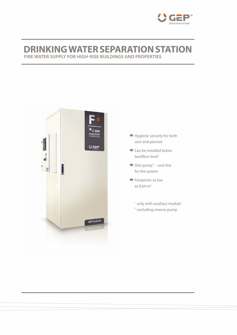
DRINKING WATER SEPARATION STATIONFIRE WATER SUPPly FOR hIGh-RISE bUIlDINGS AND PROPERTIES
Hygienic security for both user and planner
Can be installed below backflow level*
One pump** – one line for the system
Footprints as low as 0,64 m2
* only with auxiliary module ** excluding reserve pump
PAG
E 04 06 08 10 1412 16 18 20
/// GEP Industrie-Systeme Gmbh /// www.GEP-h2O.de ///
Due to the many renovation projects being car-ried out in respect of drinking water hygiene in existing installations, numerous fire water sys-tems in large properties and high rise buildings have been separated from the drinking water network over recent years. In this respect, contingent on the physical de-termining factors such as building height or network size, the problem presents itself for technical planners and executors of how to properly renovate or build new. Technologies have to be utilised which will ensure a defined
minimum supply pressure at hydraulically un-suitable hydrants and which, in so doing, will not exceed the maximum threshold value of 8 bar. In almost all German Federal States, the majority of such buildings and properties fall within the scope of the test directives of that state. To this end, the legislators specify that fire water installations are to be tested at regular in-tervals by building control authorised special-ists to ensure the effectiveness of the fire water installation in compliance with the above given example of threshold values.
The „right of continuance“ as an excuseShould flow pressures of over 8 bar be discov-ered during the technical approval inspection by state accredited specialists, there exists the widespread notion that the installation being tested still in fact enjoys the right of continuance. An interpretation that is neither endorsed by the generally recognised rules of good practice1 nor by the legislators2;3. Regarding the maximum supply pressure, the regulations in the German High-rise Building Guidelines or draft High- rise Building Guidelines2;3 and the Standard DIN 1446211 are of importance. Commenting on the draft High-rise Building Guidelines3, one passage in particular is dedicated to existing installations
Inept approach to the solutionIn deploying what appears at first glance to be an inexpensive technology, the practice of ut-ilising pressure reducers in the fire water lines is encountered time and again. Many users are un-aware that in deploying this type of valvework in the fire water supply, there is a serious risk to be assumed that the fire water installation may fail. This is a type of installation that provokes endangerment to the protection of protecting people and assets. It is not for nothing that the
where statements are made on the mitigation of the minimum flow rate or the minimum sup-ply pressure in agreement with responsible fire prevention authorities. Regarding the maximum supply pressure which, from the point of view of operational safety is also important, a devia-tion from the threshold value is not to be found. In fact, the maximum flow pressure was already limited to 7 bar in the case of older installations by virtue of the recognised rules of good practice. It was not until the appearance of the new Or-dinance MBO2 in 2008 that the above threshold value was increased to 8 bar and adopted into the subsequent application standard DIN 144621.
pertinent application standards, e.g. DIN 19884 and 144621, have been advising against the ut-ilisation of pressure reducing valves in fire water systems for decades now.The previously trusted and undisputed safe functioning of the pressure reducer in the drinking water installation4 is heavily depend-ant on the entry of dirt into this type of valve. The relevant Standard1 points in particular to the fact that only components which are
FOR FIRE WATER SUPPly
/ 01 / PRESSURE lIMITATION IN EXISTING AND NEW FACIlITIES

PAG
E03 05 07 09 1311 15 17 19
specifically suitable for fire water supply are to be fitted in fire water installations. The utilisation of this kind of valve in the fire water line network presupposes the verification of operational reliability in the form of a techni-cal assessment by an accredited test centre or the application of a product standard. For this reason, leading manufacturers of various types of pressure reducing valves specify in principle that this valve be protected by an upstream filter.
Filters fitted in the fire water line for the func-tional security of the pressure reducing valves constitute a high risk of constriction that can lead to the failure of the entire fire water instal-lation. In consequence, only coarse filters, also described as stone traps, greater than 1 mm*
for wall hydrants, for example, or greater than 5 mm for sprinkler installations, are permitted5;6. Dispensing with the fitting of filters before the pressure reducing valves contrary to the stipu-lations of the manufacturer can lead to a total failure of the control valvework and/or com-
plete interruption of the water flow. Dirt par-ticles in the fire water lines can reach extreme proportions of a such a kind unknown in drink-ing water installations. As a consequence of the long dwell period of the fire water in the pipework and its associated corrosion, substantial corrosion products and scaling occur which, particularly in the case of galvanised iron materials, are loosened when water is drawn off. In addition to deposits and corrosion products in the domestic plumbing system, particles are entrained via the service line. In the event of fire, high flow velocities oc-cur in the property service line. Particularly in the case of older public supply lines, this gives rise to massive dirt entrainment in the fire water pipework.
* In the opinion of the writer, greater penetrability should be selected even for wall hydrants, e.g. 5 mm.
p
Pressure reducing valve protected by filter
Deposits and particles in various existing fire water installations supplying hydrants
53 mm 53 mm
Safe regulation-conformant technological executionsThe objective of any technical planning or exe-cution must be to ensure the maximum supply pressure limit of 8 bar under all operating con-ditions. This means that the drawing of water
from a wall hydrant at the start of the fire-fight-ing deployment with 24 l/min up to a maximum water withdrawal rate of, for example, 600 l/ m must not exceed this threshold value.
PAG
E04 06 08 10 1412 16 18 20
/// GEP Industrie-Systeme Gmbh /// www.GEP-h2O.de ///
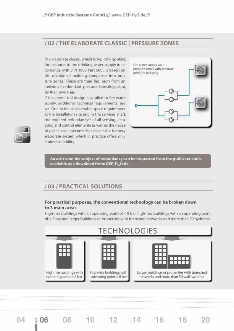
The elaborate classic, which is typically applied, for instance, to the drinking water supply in ac-cordance with DIN 1988 Part 5007, is based on the division of building complexes into pres-sure zones. These are then fed, each from an individual redundant pressure boosting plant, by their own riser.If this permitted design is applied to fire water supply, additional technical requirements1 are set. Due to the considerable space requirement at the installation site and in the services shaft, the required redundancy2;3 of all sensing, actu-ating and control elements as well as the neces-sity of at least a second riser, makes this is a very elaborate system which in practice offers only limited suitability.
/ 02 / ThE ElAbORATE ClASSIC | PRESSURE ZONES
Fire water supply viapressure zones with separatepressure boosting
/ 03 / PRACTICAl SOlUTIONS
For practical purposes, the conventional technology can be broken down to 3 main areasHigh-rise buildings with an operating point of < 8 bar, high-rise buildings with an operating point of > 8 bar and larger buildings or properties with branched networks and more than 50 hydrants.
Larger buildings or properties with branched networks and more than 50 wall hydrants
High-rise buildings with operating point > 8 bar
High-rise buildings with operating point ≤ 8 bar
TECHNOLOGIES
An article on the subject of redundancy can be requested from the publisher and is available as a download from: GEP-h2O.de.
PAG
E03 05 07 09 1311 15 17 19
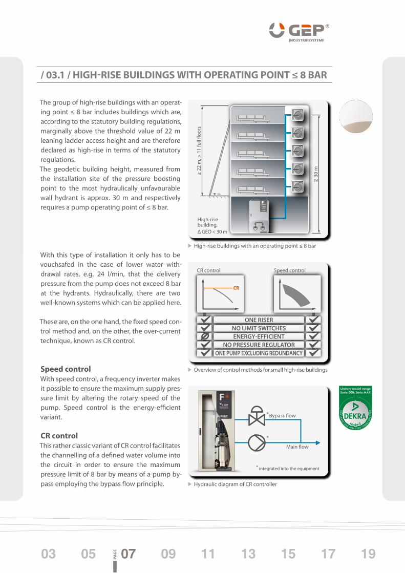
The group of high-rise buildings with an operat-ing point ≤ 8 bar includes buildings which are, according to the statutory building regulations, marginally above the threshold value of 22 m leaning ladder access height and are therefore declared as high-rise in terms of the statutory regulations.The geodetic building height, measured from the installation site of the pressure boosting point to the most hydraulically unfavourable wall hydrant is approx. 30 m and respectively requires a pump operating point of ≤ 8 bar.
With this type of installation it only has to be vouchsafed in the case of lower water with-drawal rates, e.g. 24 l/min, that the delivery pressure from the pump does not exceed 8 bar at the hydrants. Hydraulically, there are two well-known systems which can be applied here.
These are, on the one hand, the fixed speed con-trol method and, on the other, the over-current technique, known as CR control.
Speed controlWith speed control, a frequency inverter makes it possible to ensure the maximum supply pres-sure limit by altering the rotary speed of the pump. Speed control is the energy-efficient variant. CR controlThis rather classic variant of CR control facilitates the channelling of a defined water volume into the circuit in order to ensure the maximum pressure limit of 8 bar by means of a pump by-pass employing the bypass flow principle.
p
/ 03.1 / hIGh-RISE bUIlDINGS WITh OPERATING POINT ≤ 8 bAR
Unitary model rangeSerie 300; Serie MAX
tested
Hydraulic diagram of CR controller
Overview of control methods for small high-rise buildings
GL
30 m
~ ≤
≥ 22
m, >
11
full
�oor
s
High-risebuilding, Δ GEO < 30 m
DRINKING WATERSEPARATION STATION
300
Bypass �ow*
*
Main �ow
integrated into the equipment*
ONE RISERNO LIMIT SWITCHESENERGY-EFFICIENT
NO PRESSURE REGULATORONE PUMP EXCLUDING REDUNDANCY
Speed controlCR control
High-rise buildings with an operating point ≤ 8 bar
PAG
E04 06 08 10 1412 16 18 20
/// GEP Industrie-Systeme Gmbh /// www.GEP-h2O.de ///
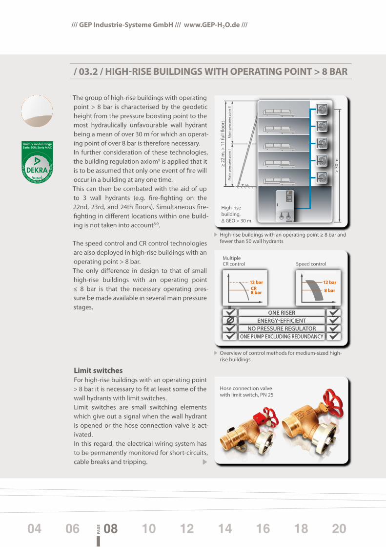
The group of high-rise buildings with operating point > 8 bar is characterised by the geodetic height from the pressure boosting point to the most hydraulically unfavourable wall hydrant being a mean of over 30 m for which an operat-ing point of over 8 bar is therefore necessary. In further consideration of these technologies, the building regulation axiom9 is applied that it is to be assumed that only one event of fire will occur in a building at any one time.This can then be combated with the aid of up to 3 wall hydrants (e.g. fire-fighting on the 22nd, 23rd, and 24th floors). Simultaneous fire- fighting in different locations within one build-ing is not taken into account8;9.
The speed control and CR control technologies are also deployed in high-rise buildings with an operating point > 8 bar.The only difference in design to that of small high-rise buildings with an operating point ≤ 8 bar is that the necessary operating pres-sure be made available in several main pressure stages.
limit switchesFor high-rise buildings with an operating point > 8 bar it is necessary to fit at least some of the wall hydrants with limit switches. Limit switches are small switching elements which give out a signal when the wall hydrant is opened or the hose connection valve is act-ivated. In this regard, the electrical wiring system has to be permanently monitored for short-circuits, cable breaks and tripping.
/ 03.2 / hIGh-RISE bUIlDINGS WITh OPERATING POINT > 8 bAR
p
Unitary model rangeSerie 300; Serie MAX
tested
Overview of control methods for medium-sized high- rise buildings
High-rise buildings with an operating point ≥ 8 bar and fewer than 50 wall hydrants
GL
> 30
m
High-risebuilding, Δ GEO > 30 m
≥ 22
m, >
11
full
�oor
sM
ain
pres
sure
zon
e I
Mai
n pr
essu
re z
one
II
DRINKING WATERSEPARATION STATION
300
MultipleCR control Speed control
ONE RISERENERGY-EFFICIENT
NO PRESSURE REGULATORONE PUMP EXCLUDING REDUNDANCY
Hose connection valve with limit switch, PN 25

PAG
E03 05 07 09 1311 15 17 19
A division of the building into several electri-cal groups, e.g. every 8 floors, enables catering for individual operating points by means of pressure boosting when a limit switch is triggered. If, for example, a wall hydrant on the 20th floor
is activated, the pump provides a supply pres-sure of 12 bar. On the other hand, if a wall hydrant is triggered in the underground car park, a supply pressure is provided of only 5 bar.
Pressure decreasePrerequisite for this kind of trend-setting tech-nology is that, along with the appropriately rapid pressure build up, a reliable decrease in pressure takes place within 2.5 seconds inde-pendent of the size of the line network. In order to safeguard against unacceptable pressures, the above reaction time has been assigned a safety factor in accordance with GEP in-house standards. This is yielded by the smallest nec-essary time span required for a hose connec-tion valve to open and the dimensionally stable hose to fill up.
Pressure decrease reaction time
2 s
For further information see our datasheet: 2" hose connection valve PN 25
Emergency bypass line and safety valveIn order to guarantee reliable pump opera-tion, the minimum pumped volume must not fall below a certain level in accordance with DIN 14462. Depending on pump manufac-turer, this is between 10 and 20 percent of the nominal pump capacity. With the cascade- controlled Drinking Water Separation Station by GEP IndustrieSysteme this is ensured by means of a bypass line.In general, this is designated an emergency bypass line and is integrated into the Drinking Water Separation Station. Moreover, in stand-ard fire water systems, pressures due to expan-sion above the maximum pressure stage are to be ruled out. A safety valve circuit within the Drinking Water Separation Station guarantees the requirements in terms of the Standard.
DRINKING WATERSEPARATION STATION
300
Opendischarge
Integrated intothe equipment
Emergency bypass line
Safetyvalve circuit
Drinking Water Separation Station
PAG
E04 06 08 10 1412 16 18 20
/// GEP Industrie-Systeme Gmbh /// www.GEP-h2O.de ///
/ 03.3 / hIGh bUIlDINGS | lARGER PROPERTIES
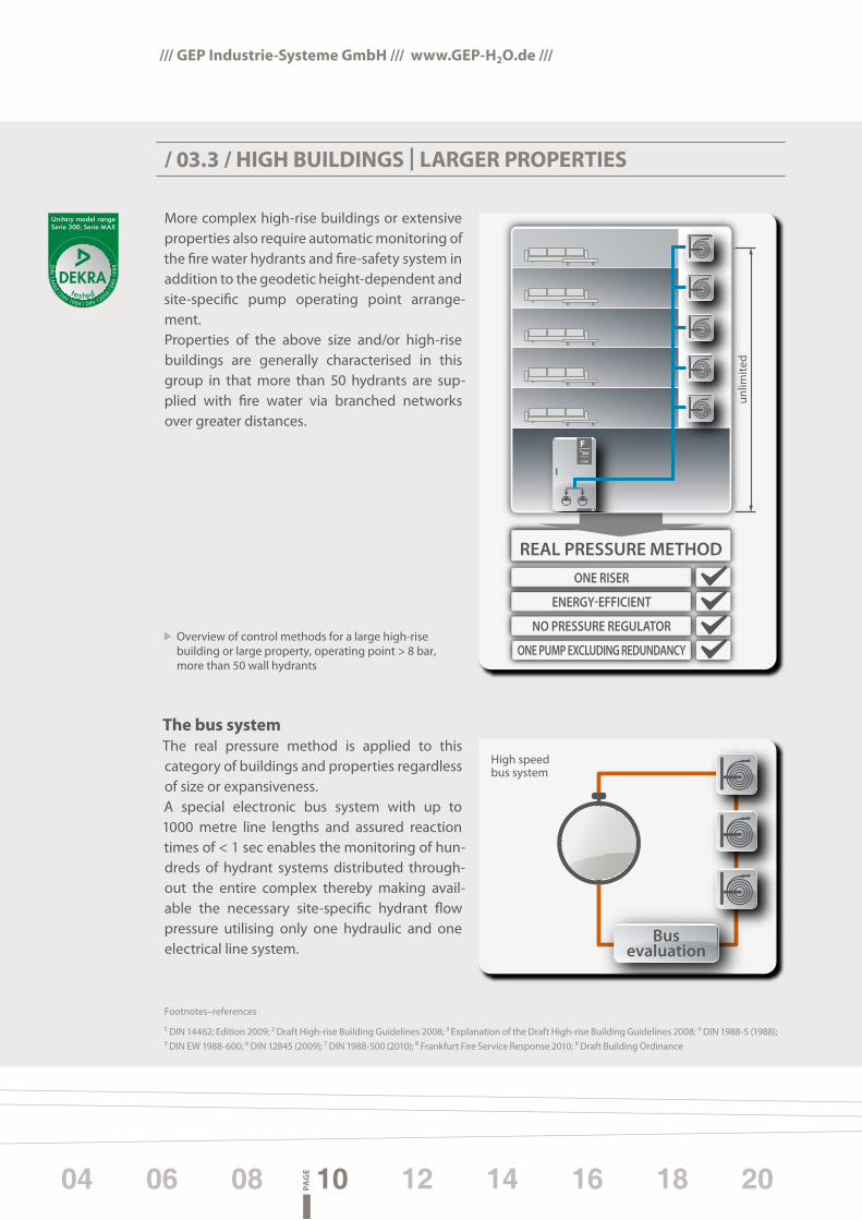
More complex high-rise buildings or extensive properties also require automatic monitoring of the fire water hydrants and fire-safety system in addition to the geodetic height-dependent and site-specific pump operating point arrange-ment.Properties of the above size and/or high-rise buildings are generally characterised in this group in that more than 50 hydrants are sup-plied with fire water via branched networks over greater distances.
The bus systemThe real pressure method is applied to this category of buildings and properties regardless of size or expansiveness.A special electronic bus system with up to 1000 metre line lengths and assured reaction times of < 1 sec enables the monitoring of hun-dreds of hydrant systems distributed through-out the entire complex thereby making avail-able the necessary site-specific hydrant flow pressure utilising only one hydraulic and one electrical line system.
Unitary model rangeSerie 300; Serie MAX
tested
Overview of control methods for a large high-rise building or large property, operating point > 8 bar, more than 50 wall hydrants
REAL PRESSURE METHODONE RISER
ENERGY-EFFICIENT
NO PRESSURE REGULATOR
ONE PUMP EXCLUDING REDUNDANCY
unlim
ited
DRINKING WATERSEPARATION STATION
300
High speedbus system
Busevaluation
1s
Footnotes–references
1 DIN 14462; Edition 2009; 2 Draft High-rise Building Guidelines 2008; 3 Explanation of the Draft High-rise Building Guidelines 2008; 4 DIN 1988-5 (1988); 5 DIN EW 1988-600; 6 DIN 12845 (2009); 7 DIN 1988-500 (2010); 8 Frankfurt Fire Service Response 2010; 9 Draft Building Ordinance

PAG
E03 05 07 09 1311 15 17 19
Taking one of the highest buildings in Germany, the Deutsche Bank HQ in Frankfurt am Main, as an example, approximately 200 wall hydrants with only one riser per building are monitored and securely served by only one pump and one additional reserve pump.Another example is the Rhön Clinic property. The entire complex extends over several hec-tares of ground. Apart from the various admin-istration buildings, wards, high-rise buildings and other items of property are located on this site, all of which have to be provided with fire water.The classical solution would have resulted in supply being provided by multiple pressure boosting plants throughout the whole grounds. By using the real pressure method, the entire fire water provision, including external hydrants can be secured using only one pump and line system.
Deutsche Bank in Frankfurt/Main, Germany real pressure method
American Express in Frankfurt/Main, Germany real pressure method
Property in Berlin, Germany real pressure method

/// GEP Industrie-Systeme Gmbh /// www.GEP-h2O.de ///
1 Installation of a Drinking Water Separation Station below backflow level | Fire water supply using variable speed high-rise building control | Floor- dependent triggering and symmetrical redundancy, stage III | Basis: Deutsche Hochhaus-Richtlinie (German high-rise building guidelines) edition 08
Drinking waterconsumers
-5°C
Underground car park
FIL
Hig
h-ri
se b
uild
ing
= m
ore
than
12
full
�oor
s or
lean
ing
ladd
er a
cces
s >
22 M
eter
, unl
imit
ed p
umpi
ng h
ead
One
pre
ssur
e zo
ne fo
r unl
imit
ed b
uild
ing
heig
ht
m3
000
Installation possible below back�ow level.*
One Drinking Water Separation Station, one pipeline system.
No pressure reducer –always < 8 bar
FreierAuslauf
GOK
The use of pressurereducing valves isto be avoided.DIN 1988-5DIN 1988-60DIN 14462
bar
GL
3 x 200 l/min4,50 bar
4,50-8,00 bar
4,50-8,00 bar
4,50-8,00 bar
4,50-8,00 bar
4,50-8,00 bar
optional50th �oor
43rd to 49th �oor
42th �oor
41th �oor
10th �oor
3rd to 9th �oor
2nd �oor
1st �oor
Basement
Automatic seal-o�
OpenDischarge
Wet-dry module
Emergencypump drainage
PUBLIC DRINKING WATER
TRINKWASSERTRENNSTATION
endorsedby:
Unitary model rangeSerie 300; Serie MAX
tested
German Patent
and Trademark
O�ce
Proc
ess patent
registered
/ 04 / hIGh-RISE CONTROl by REAl PRESSURE METhOD
No pressure-reducing valves and always < 8.0 bar
Installation below backflow level*
Stage III redundancy of actuators and control elements
Optional frost protection in underground car park
Footprint as low as 1,3 m2 (1,60 x 0,8 m) One pressure boost with two pumps,
one fire water line for the entire building
Reference exampleDEUTSCHE BANKFrankfurt/M., Germany
Reference exampleAMERICAN
EXPRESSFrankfurt/M., Germany
BUSPROCESSING
PAG
E04 06 08 10 1412 16 18 20
Information on the real pressure method can also be found in our Guide to Sprinkler Equipment
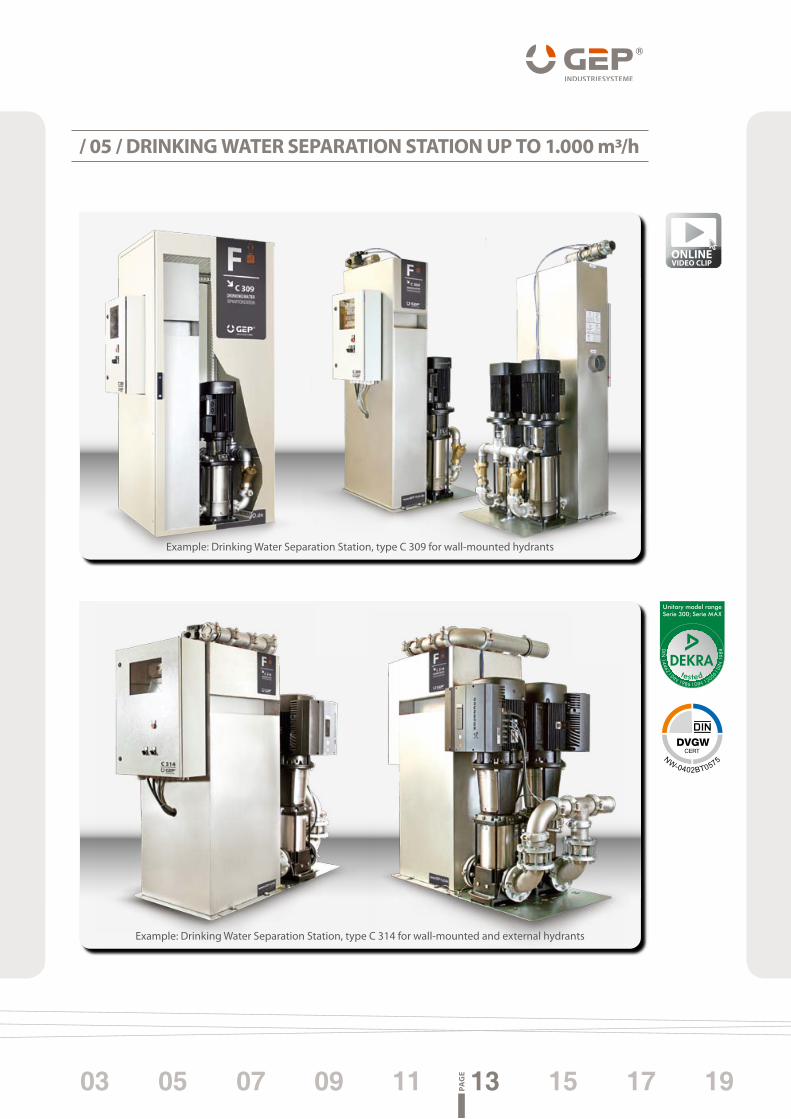
Example: Drinking Water Separation Station, type C 309 for wall-mounted hydrants
Example: Drinking Water Separation Station, type C 314 for wall-mounted and external hydrants
/ 05 / DRINKING WATER SEPARATION STATION UP TO 1.000 m3/h
Unitary model rangeSerie 300; Serie MAX
tested
ONLINEVIDEO CLIP
PAG
E03 05 07 09 1311 15 17 19

Guide: Drinking Water Separation Station for wall-mounted and external hydrantsGuide: Drinking Water Separation Station for sprinkler systems up to 16,600 l/minGuide: Drinking Water Separation Station for rainwater utilisation in large-scale systemsGuide: Drinking Water Separation Station for indirect connection of drinking water systemsTechnical documentation: Drinking Water Separation StationDatasheet: 2" hose connection valve PN 25 Datasheet: Pump-emergency drainage/Installation below backflow level
No guarantee is given or implied by the information contained in the brochure. We reserve the right to make alterations without prior notice.
FURThER bROChURES ON ThE SUbJECT OF DRINKING, PROCESS AND FIRE WATER TEChNOlOGy
/// GEP Industrie-Systeme Gmbh /// www.GEP-h2O.de ///
For over a decade now, we have been spe-cialising exclusively in the field of drinking, process and fire water supply. We would like to do justice to your require-ments through our personal, qualified cus-tomer advice, long product service life and the intrinsic values of our company manage-ment.
We hope you will find the presentation of our products and services to be of interest and look forward to cooperating closely with you.
A WARM WElCOME TO GEP INDUSTRIESySTEME
DAT
ASH
EET
Hose connection valve optionally with limit switch and connecting pieceassisted by:
PRO
DU
CTD
ESCR
IPTI
ON
GEP hose connection valve – Tender specification Hose connection valve for wall-mounted hose reel systems type F, can be integrated in all wall-mounted hose reel systems in accordance to DIN 14461, resistant to cor-rosive water, wetted parts made of red brass in accordance to EN 12502, self-greasing EPDM lip seal, maintenance-free spindle, EPDM-WN21 seat seal with pivoted cone protected against pressure surges, spindle thread, unwetted parts, in accordance with DIN 14 461-3, rated pressure PN 25, including holder for optional GEP limit switch, grooved end DN 50 (2’’)
DIM
ENSI
ON
S
grooved end H1
= ap
prox
. 110
mm
D =
100
mm
L1 = 133 – 152 mm
Nominal width DN 50 Overall height (H1) approx. 110 mm Overall length (L1) 133 - 152 mm Pipe connection size (d) 60.3 mm Handwheel diameter (D) 100 mm Weight 2.25 kg Max. flow rate (kvs) 50.2 m³/h Loss factor (ZETA) 3.9
MAT
ERIA
LS Casing, top, spindle, cone, valve seat red brass Top seal, spindle seal, cone seal EPDM Cone nut, washer SSHead end brass Handwheel cast aluminium
FIGURE 144 61
BRÜCKENSTRASSE 11D - 08297 ZWÖNITZ
[email protected] +49 (0)3 77 54. 33 61.10
T +49 (0)3 77 54. 33 61.44T +49 (0)3 77 54. 33 61.0
GEP INDUSTRIE-SYSTEME GMBH
PN 25
2" HOSE CONNECTION VALVE PN 25PN 25 WITH GROOVED END
entirely red brass | in wetted area in accordance with EN 12502
maintenance-free screw sealing
based on DIN 14461
pressure stage (PN) 25 bar
connection: DN 50 (2")
DRI
NKI
NG
WAT
ER SE
PARA
TIO
N ST
ATIO
Nfo
r rai
nwat
er u
tilis
atio
n in
larg
e-sc
ale
syst
ems
GU
IDE
DRI
NKI
NG
WAT
ER SE
PARA
TIO
N ST
ATIO
Nfo
r spr
inkl
er s
yste
ms
up to
16,
600
l/min
GU
IDE
DRI
NKI
NG
WAT
ER SE
PARA
TIO
N ST
ATIO
Nfo
r ind
irect
con
nect
ion
of d
rinki
ng w
ater
sys
tem
s
TEC
HN
ICA
LD
OC
UM
ENTA
TIO
N
DRI
NKI
NG
WAT
ER SE
PARA
TIO
N ST
ATIO
Nfo
r wal
l-mou
nted
and
ext
erna
l hyd
rant
s
GU
IDE
Rudolf GruberSales Manager
Enrico GötschManaging Director

endorsedby:

Rv. L
F-TW
TS-H
H-B
BAB
EN
GEP INDUSTRIE-SYSTEME GMBH
BRÜCKENSTRASSE 11D–08297 ZWÖNITZ
T +49 (0)37754. 3361.44T +49 (0)37754. 3361.0F +49 (0)37754. 3361.10
EN
DE
PROCESS WATER,FIRE WATERDRINKING WATERSUPPLY


