December 20, 2006 Page 1 Drinking Water Treatment Residual Injection Wells Technical Recommendations EXECUTIVE SUMMARY Background Faced with increasing water demands and new drinking water standards, many communities are turning to marginal source waters such as brackish ground water and advanced drinking water treatment technologies such as reverse osmosis (RO). The use of these advanced treatment technologies has allowed communities to access water supplies that were previously considered too costly to utilize. However, technologies such as RO can produce large quantities of drinking water treatment residuals (DWTR). From an economic perspective, injection wells are being considered as one of the preferred options for disposal of DWTR. The Underground Injection Control (UIC) Program’s National Technical Workgroup (NTW) has been charged with evaluating technical issues and developing recommendations regarding the use of injection wells for DWTR disposal. These technical recommendations will assist UIC program management in its ongoing effort to develop an Agency position on DWTR disposal via injection wells. Legal and policy issues will be further considered during the development of the Agency position and are outside the scope of this NTW technical paper. Findings and Analysis The current viable DWTR injection options are Class I hazardous and nonhazardous waste injection wells, Class II enhanced oil recovery (EOR) injection wells, and Class V injection wells. Class I wells inject industrial fluids or municipal wastewater beneath the lowermost underground source of drinking water (USDW) and are designated as hazardous or nonhazardous, depending on the type of fluids injected. Class II EOR wells inject the mineralized water (brine) or other makeup fluids back into the formation from where it was produced (usually below the lowermost USDW) to enhance oil and gas recovery. Class V injection wells are mostly shallow wells that inject into or above USDWs, but some Class V wells are deep wells that inject below the lowermost USDW (e.g., spent brine return flow wells). The use of deep Class V injection wells that inject below the lowermost USDW is an option for DWTR disposal. However, depending on the characteristics of the DWTR, meeting the non- endangerment standard may be difficult for Class V DWTR injection wells that inject into or above a USDW. Class II disposal wells (Class II-D), 1 Class II hydrocarbon storage wells (Class II-H), Class III wells, and Class IV wells are not options for DWTR injection wells under the current regulations. Class II-D wells are limited to the disposal of fluids associated with conventional oil or natural gas production or natural gas storage operations, whereas Class II-H wells are used for the storage of liquid hydrocarbons. Class III wells are, by definition, used solely for the injection of fluids for mineral 1 Class II-D wells could be dually permitted with either an additional Class I or Class V permit to enable the disposal DWTR. Class II-D permit/authorization wells cannot accept DWTR wastes without dual permitting (see UIC Program Guidance #24 for additional information).
Transcript
December 20, 2006 Page 1
Drinking Water Treatment Residual Injection Wells
Technical Recommendations
EXECUTIVE SUMMARY Background Faced with increasing water demands and new drinking water standards, many communities are turning to marginal source waters such as brackish ground water and advanced drinking water treatment technologies such as reverse osmosis (RO). The use of these advanced treatment technologies has allowed communities to access water supplies that were previously considered too costly to utilize. However, technologies such as RO can produce large quantities of drinking water treatment residuals (DWTR). From an economic perspective, injection wells are being considered as one of the preferred options for disposal of DWTR.
The Underground Injection Control (UIC) Program’s National Technical Workgroup (NTW) has been charged with evaluating technical issues and developing recommendations regarding the use of injection wells for DWTR disposal. These technical recommendations will assist UIC program management in its ongoing effort to develop an Agency position on DWTR disposal via injection wells. Legal and policy issues will be further considered during the development of the Agency position and are outside the scope of this NTW technical paper.
Findings and Analysis
The current viable DWTR injection options are Class I hazardous and nonhazardous waste injection wells, Class II enhanced oil recovery (EOR) injection wells, and Class V injection wells.
Class I wells inject industrial fluids or municipal wastewater beneath the lowermost underground source of drinking water (USDW) and are designated as hazardous or nonhazardous, depending on the type of fluids injected. Class II EOR wells inject the mineralized water (brine) or other makeup fluids back into the formation from where it was produced (usually below the lowermost USDW) to enhance oil and gas recovery. Class V injection wells are mostly shallow wells that inject into or above USDWs, but some Class V wells are deep wells that inject below the lowermost USDW (e.g., spent brine return flow wells). The use of deep Class V injection wells that inject below the lowermost USDW is an option for DWTR disposal. However, depending on the characteristics of the DWTR, meeting the non-endangerment standard may be difficult for Class V DWTR injection wells that inject into or above a USDW.
Class II disposal wells (Class II-D),1 Class II hydrocarbon storage wells (Class II-H), Class III
wells, and Class IV wells are not options for DWTR injection wells under the current regulations. Class II-D wells are limited to the disposal of fluids associated with conventional oil or natural gas production or natural gas storage operations, whereas Class II-H wells are used for the storage of liquid hydrocarbons. Class III wells are, by definition, used solely for the injection of fluids for mineral
1 Class II-D wells could be dually permitted with either an additional Class I or Class V permit to enable the disposal DWTR. Class II-D permit/authorization wells cannot accept DWTR wastes without dual permitting (see UIC Program Guidance #24 for additional information).
December 20, 2006 Page 2
extraction. Class IV wells inject are banned nationwide except for limited ground water remediation activities.
The NTW identified 101 DWTR currently permitted or authorized injection wells. These
wells are classified as Class I nonhazardous or Class V wells, and the permit requirements, where specified, are generally similar to Federal Class I requirements.
The NTW subgroup surveyed all EPA Regions in 2006 to determine which regions, states, and territories have authorized DWTR injection wells, how permitted or authorized wells are classified, and what requirements are being applied to DWTR injection wells. This survey identified a total of 101 permitted or authorized DWTR injection wells. Florida has the highest number (75) of DWTR injection wells. Other states and territories with DWTR injection wells include the Commonwealth of the Northern Mariana Islands (CNMI), Texas, Kansas, Utah, and Hawaii. Of the 101 injection wells, the majority (63) are Class I nonhazardous injection wells. There are 38 Class V injection wells, of which, 31 have been permitted and 7 have been rule-authorized. All of the Class V injection wells that the NTW was able to gather information on are either deep or inject below the lowermost USDW. No information on shallow disposal wells injecting into or above a USDW was provided by the regions or states who responded even though this information was requested by the NTW.
The NTW also reviewed a sample of seven permits (two in draft form) and one letter of
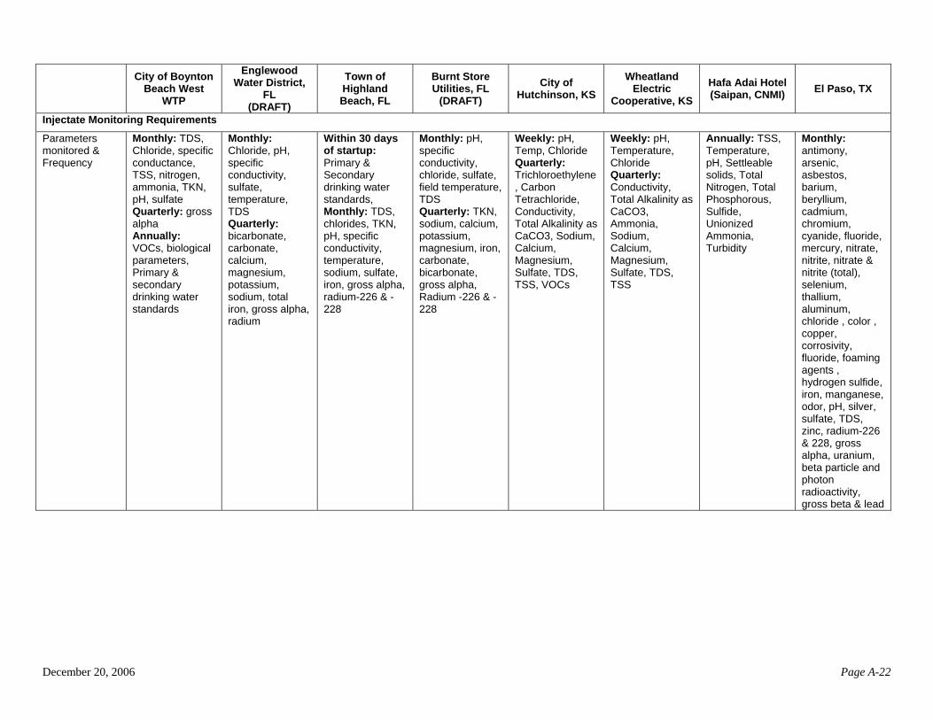
authorization. The permits/authorizations were issued by Florida, Kansas, CNMI, and Texas. The materials reviewed cover 14 of the 101 authorized DWTR injection wells, 5 Class I nonhazardous waste disposal wells, and 9 Class V injection wells. The requirements for the Class V injection wells generally appear to be as comprehensive as the requirements for the Class I injection wells. Most of the permits/authorizations contain specific casing, cementing (continuous in some states or as needed in other states to protect USDWs), and tubing requirements. All of the permits specify a maximum daily injection volume [up to 2.4 million gals/day (MGD) per well] and injection pressure. All operators must monitor injection flow rate, volume, and pressure (most permits specify continuous monitoring). Other parameters specified in some of the permits include wellhead annulus pressure, initial and/or final totalizer reading, and pressure fall-off testing.
All eight permits/authorizations include mechanical integrity test (MIT) requirements at least
every 5 years (one permit has an annual MIT requirement and one requires MIT every 3 years). The permits/authorizations specify various MIT methods, including TV survey, pressure testing, radioactive tracer survey, and temperature logging. In addition, all eight operators have injectate monitoring requirements (either weekly, monthly, quarterly, and/or annually). In addition, all operators must monitor for pH, total dissolved solids (TDS), and total suspended solids (TSS); most also monitor for chloride and conductivity. Other commonly noted parameters for monitoring among the permits/authorizations include temperature, sulfate, sodium, and Total Kjehldahl Nitrogen (TKN) or nitrogen. Some permits/authorizations also require monitoring for gross alpha or radium-226/228 and other contaminants regulated under primary and secondary drinking water regulations.
The NTW found similarities between DWTR and the fluids typically disposed of into Class I nonhazardous, Class II-D, Class II-EOR, and certain Class V injection wells.
Liquid DWTR are generally characterized by high concentrations of TDS and TSS. In addition, DWTR may have high or low pH and significant concentrations of heavy metals (e.g., arsenic, lead, and aluminum); fluoride, sodium, chloride, and other salts; and radionuclides and their daughter products. There are also concerns about geochemical interactions between the liquid DWTR (i.e., rejected water
December 20, 2006 Page 3
or concentrate) and the native formation water or the lithology of the receiving formation. Silica, gypsum, and calcite can precipitate and reduce the permeability of the receiving formation. Fines, colloidal material, iron corrosion products, and clay can also have a negative impact on the injection well and receiving formation.2
The NTW compared these general characteristics of DWTR to those of fluids received by
various injection wells. Based on the reviewed information, most DWTR are unlikely to be classified as hazardous or radioactive waste, with the possible exception of highly concentrated DWTR resulting from the removal of metals such as barium, mercury, arsenic, and radionuclides. Further observations include:
• Similarities between DWTR and fluids received by Class I nonhazardous and municipal wells (e.g., containing metals, nitrates, and pathogens).
• DWTR are often high in TDS and are similar in nature to typical Class II fluids.
However, existing regulations do not allow the use of non-EOR Class II wells for the injection of DWTR.
• DWTR are similar to certain spent brine from the extraction of halogens and their salts
that are disposed of via injection wells that are categorized as Class V injection wells. Spent brine injection wells located in Arkansas and Michigan are permitted as Class V wells with construction, operation, and monitoring requirements similar to those of Class II-D injection wells. The spent brine has high concentrations of TDS like DWTR but may contain other contaminants of concern (e.g., solvents in spent brine from bromine production in Arkansas) that are not present in DWTR fluids.
Because of these similarities, the NTW has considered the requirements associated with these wells as potential models for DWTR injection wells. Recommendations
In developing the recommendations for using injection wells for the disposal of DWTR, the NTW evaluated existing classes of injection wells, minimum Federal regulatory requirements, current state and regional management approaches, DWTR constituents, and comparative properties of fluids currently disposed of via various injection well classes. Cost-saving measures were incorporated into the decision-making process because drinking water facilities operate on limited resources. Additionally, the NTW did not constrain its analysis by the existing well class option (i.e., Class I, Class II EOR, and Class V) requirements. Instead, the recommendations were developed to specifically address the risks posed by DWTR injection. The resulting recommendations address the concern that the existing regulations contain unnecessary administrative, construction, operation, and monitoring requirements because they are not specific to DWTR injection. Another benefit of using this approach is that it allowed for flexibility and additional cost saving opportunities.
2 Fubryka-Martin 2006.
• MIT Internal. The NTW recommends that a pressure test be performed prior to the initial operation of the well, periodically throughout the life of the well (at intervals determined by the UIC Program Director), and when the tubing and packer have been reseated.
December 20, 2006 Page 4
Highlights of the NTW recommendations include the following: • Requirement for a Permit. The NTW recommends that DWTR injection wells be
permitted instead of rule authorized due to the injectate volumes, potential for corrosion, and the need to prevent fluid movement.
• Area of Review (AOR). The NTW recommends a minimum ¼-mile radius AOR for
DWTR injection wells. In addition, the NTW recommends that the Zone of Endangering Influence (ZEI) be calculated to ensure that a fixed radius of ¼ mile is sufficient to ensure that USDWs are protected from unintended movement of fluids resulting from existing formation pressures or pressure increase due to long-term disposal activities.
• Casing and Cementing. The NTW recommends that UIC Program directors be given
flexibility in determining the casing and cementing requirements to adequately protect USDWs from DWTR injection. In setting these requirements, the NTW strongly recommends that permitting authorities consider depth to injection zone; injection pressure, external pressure, internal pressure, and axial loading; hole size; size and grade of casing strings; corrosiveness of injected and formation fluids; temperature; lithology of injection and confining intervals; and type or grade of cement. In addition, the NTW recommends that compatible construction materials are provided to prevent corrosion and leaks.
• Tubing and Packer. The NTW recommends that a tubing and packer be required given
the corrosive nature of the DWTR fluids and as an added layer of protection. The NTW also recommends that the annulus between the tubing and the long-string casing be filled with an appropriate fluid at an approved pressure.
• Open-Hole Logging. The NTW recommends that the following logs be considered for
the open hole: Electric, Porosity, Gamma Ray logs (geologic data collection), and Caliper logs (cementing program data collection).
• Cased-Hole Logging. The NTW recommends that either a Cement Bond log or
Temperature log be run after the well is completed. • MIT External. The NTW recommends the following logs be considered prior to the
initial operation of the well and periodically throughout the life of the well: Radioactive Tracer, Oxygen Activation, Temperature, Noise or Cement Evaluation. Although the typical interval for these logs would be five years, the appropriate interval should be determined based on the nature of the formation and injected fluids.
• Reservoir Pressure Determination. The NTW recommends consideration of either a
pressure fall-off test or a static reservoir pressure (dip-in) test at an interval determined by the UIC Program Director.
December 20, 2006 Page 5
• Operating. The NTW recommends that, except during stimulation, the injection pressure shall not exceed injection zone fracture pressure to protect the confining zone from fracturing. Fracturing of the injection zone could shorten the useful life of the well by limiting the injection zone from accepting fluids or may allow for the migration of the injectate outside the intended zone and possibly into a USDW. In addition, the NTW strongly recommends that injection between the outermost casing and the well bore be prohibited where USDWs are present.
• Monitoring. The NTW recommends that the UIC Program Director be given discretion
to monitor the DWTR injectate at time intervals sufficient to yield data representative of its characteristics.
• Reporting. The NTW recommends that a report covering monitoring data, injectate
results, and testing results be submitted annually, at a minimum. The NTW also strongly recommends that the operator be required to notify the UIC Program Director within 24 hours if mechanical integrity is lost.
• Closure and Post Closure Care. The NTW recommends that the UIC Program be given
discretion to determine the appropriate DWTR well plugging and abandonment requirements that are protective of USDWs and meet the general requirements laid out at 40 CFR §146.10. The NTW does not recommend post-closure monitoring because it is not likely that DWTR will be considered hazardous. However, UIC Program Directors may wish to consider using post-closure monitoring on a case-by-case basis.
• Financial Assurance. The NTW recommends that financial assurance be required for
DWTR injection wells to ensure that funds are available for proper plugging and abandonment. The NTW suggests that Headquarters explore the use of alternative financial assurance mechanisms such as tax or rate adjustment, because DWTR facilities are typically associated with municipalities.
• Public Notification. Public notification for DWTR injection well permitting allows for
an open decision-making process where the public can provide valuable inputs that may not otherwise be available through the permit data collection process. The notification process also builds public confidence by allowing for an open exchange of information among the public, the operator, and the permitting authority.
The NTW estimates that the cost of constructing a DWTR injection well based on the
recommendations outlined in this report would vary from $500,000 to $1.25 million depending on the specific drilling and construction requirements. The majority of the costs associated with an injection well is attributed to the construction phase, while logging, operating, and reporting are a small portion of the total cost. It is important to note that the typical life expectancy of a properly operated and maintained well is about 40 to 50 years. The anticipated costs of the recommendations laid out in this report are comparable to Class I nonhazardous or Class II-D well costs. The NTW cautions that due to the level of flexibility built into the recommendations, it is difficult to estimate exact costs for constructing and operating DWTR injection wells. Finally, states may impose more stringent requirements that could impact total costs. Next Steps
December 20, 2006 Page 6
During the development of the report, the NTW found several data gaps or other areas where
follow-up actions are recommended. These are as follows:
• The NTW found very little specific information regarding small shallow systems (e.g., Class V large capacity septic systems or drywells that receive DWTR) beyond the suspicion that such systems exist. Therefore, the NTW recommends that HQ undertake an effort to specifically gather information on small shallow DWTR systems and develop recommendations for their operation.
• The NTW realizes that the recommendations and benefits discussed in this report may be
financially unattainable for smaller drinking water systems. Therefore, the NTW proposes that HQ consider undertaking an affordability analysis subsequent to determining the inventory of small systems currently inject or plan to inject DWTR to determine potential impacts of the recommendations. The NTW also recommends that HQ consider evaluating capacity-building measures that would assist smaller systems in implementing these recommendations.
• Because there is a lack of comprehensive national data on DWTR, the NTW recommends that
HQ undertake a data collection effort to better understand how the constituents found in liquid DWTR relate to raw water quality and to the treatment process employed as well as the geochemical interactions between the DWTR and the formation water.
Finally, the NTW recommends that HQ develop an implementation strategy for the recommendations contained in this report that includes policy and legal analysis.
December 20, 2006 Page 7
1.0 INTRODUCTION 1.1 Background Drinking water treatment facilities use a variety of treatment processes to remove contaminants from the water they produce for consumers. Treatment processes include technologies such as reverse osmosis (RO) to treat water from mineralized aquifers previously considered too costly to treat. Water treatment facilities also employ advanced treatment processes to address recent drinking water standards such as arsenic or radionuclides. The Drinking Water Treatment Residuals (DWTR) formed as a result of such processes can contain concentrated salts, metals, and radioactive and/or hazardous materials. DWTR may also be produced indirectly when dewatering slurry or sludge (semi-solid wastes).
Injection wells are increasingly being evaluated as one of the preferred disposal options for DWTR disposal from a cost perspective. To date, more than 100 DWTR injection wells have been permitted or otherwise authorized by regions and states. Most of these wells are for the disposal of RO reject waters. Interest in DWTR injection wells can be attributed to the rising popularity of advanced technologies that produce relatively large volumes of liquid waste, the increasing use of marginal source waters (e.g., brackish ground water), and the limitations imposed by various environmental programs (e.g., Clean Water Act programs) on other disposal options. Certain communities have relied on DWTR injection wells to meet the disposal needs created by rising water demands and/or new drinking water standards. The use of these treatment technologies has allowed communities to access water supplies that were previously considered too costly.
Over the past decade, the EPA has assessed information on injection wells and the risks posed by
the various injection wells on underground sources of drinking water (USDWs). For example, in 1999 EPA completed a study of Class V injection wells to develop background information on the risks these injection wells pose to USDWs. In addition, in 2001 EPA published a study that summarizes risks associated with Class I injection wells. However, these previous studies did not specifically address the risks posed by DWTR injection wells. The Underground Injection Control (UIC) Program’s National Technical Workgroup (NTW) has been charged with evaluating technical issues and developing recommendations regarding the use of injection wells for DWTR disposal. These recommendations will assist UIC program management in its ongoing effort to develop an Agency position on DWTR disposal via injection wells. Legal and policy issues will be considered during the development of the Agency position. These legal and policy issues are outside the scope of this NTW technical paper.
The costs of providing drinking water and wastewater treatment for a community are high.
EPA’s Office of Water has estimated that over the past 20 years communities have spent more than $1 trillion (in 2001 dollars) on the treatment and supply of drinking water and the treatment and disposal of wastewater. The anticipated increase in the use of marginal aquifers as a source of drinking water will increase the cost to treat this water and to properly dispose of the DWTR generated. To address these rising costs, EPA has encouraged communities to develop Sustainable Infrastructure (SI) strategies to ensure that there are sufficient revenues in place to support these costs. As communities develop their SI strategies, they need to be aware not only of their future water needs but also if those needs require the use of marginal sources of water.
Drinking water treatment facilities must incur the cost of disposing of generated DWTR whether the chosen method of disposal is injection, direct discharge to surface water, or other proper disposal methods. In developing the suggested minimum technical recommendations for DWTR injection wells contained in this report, the NTW strove to meet the goals of SI by making recommendations that would
December 20, 2006 Page 8
increase the operational longevity of the well to provide safe/protective injection while attempting to keep overall costs down. Even with those considerations, the anticipated costs for the installation of an injection well to properly manage these fluids can exceed $1 million. This figure does not take into account the costs to maintain and operate the well after installation which can range from $10,000 to $20,000 annually depending on the testing requirements and their frequency. Therefore, it is important that a community account for these costs in its SI strategy in addition to developing ways of protecting the existing water supply and conserving water resources should they decide to utilize it.
1.2 Charge to the NTW
States and regions have asked for technical guidance in setting appropriate permitting criteria for
DWTR injection well construction, operation, and monitoring. As part of the research into DWTR injection, the NTW has been charged with reviewing existing construction approaches for DWTR injection wells and developing a set of construction, operating, and monitoring recommendations that could be used for DWTR injection wells.
To meet this charge, the NTW has developed a technical report that:
• Identifies existing classes of injection wells that are available for DWTR disposal (Section 2).
• Summarizes the minimum Federal regulatory requirements for construction, operation,
and monitoring for these well classes (Section 3).
• Discusses existing state and regional approaches for managing DWTR injection wells and construction, operation, and monitoring criteria currently in use (Section 4).
• Characterizes the known volumes and geochemical properties of DWTR fluids and their
potential impacts on formation performance (Section 5).
• Discusses how these fluids compare to fluids typically disposed of via Class I, II, and V injection wells (Section 6).
• Recommends minimum technical recommendations including construction, operation,
and monitoring that are protective of USDWs (Section 7). 1.3 Technical Workgroup Process As stipulated in the charter, after the assignment of a task by EPA’s UIC Management, the NTW forms a subgroup to develop an initial option paper (this report). The subgroup includes a regional management lead and EPA and State NTW membership who have expertise or interest in the area. In this case, the subgroup included three EPA members and two state members. Several EPA regions also assisted the subgroup. The subgroup is responsible for soliciting information from the literature and drafting the report. The initial report is distributed among the entire NTW for comment; the subgroup then consolidates and addresses these comments. Once the paper is finalized, it is forwarded to UIC Program management for consideration.
December 20, 2006 Page 9
2.0 EXISTING UIC DISPOSAL OPTIONS FOR DWTR
Drinking water treatment facilities and drinking water program managers are challenged to find a balance between appropriate treatment technologies, safe waste disposal practices, worker safety, and cost, while ensuring compliance with drinking water regulations for maximum public health protection. Discharge of DWTR to surface waters or to municipal sewer systems is the most common choice for disposal at this time. However, as noted in Section 1, injection wells are increasingly being considered as a disposal option, especially in inland areas where opportunities to discharge to surface waters or to sewer systems are limited.
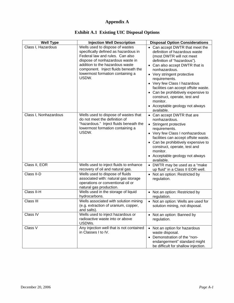
Current UIC regulations define five classes of injection wells, but do not explicitly include
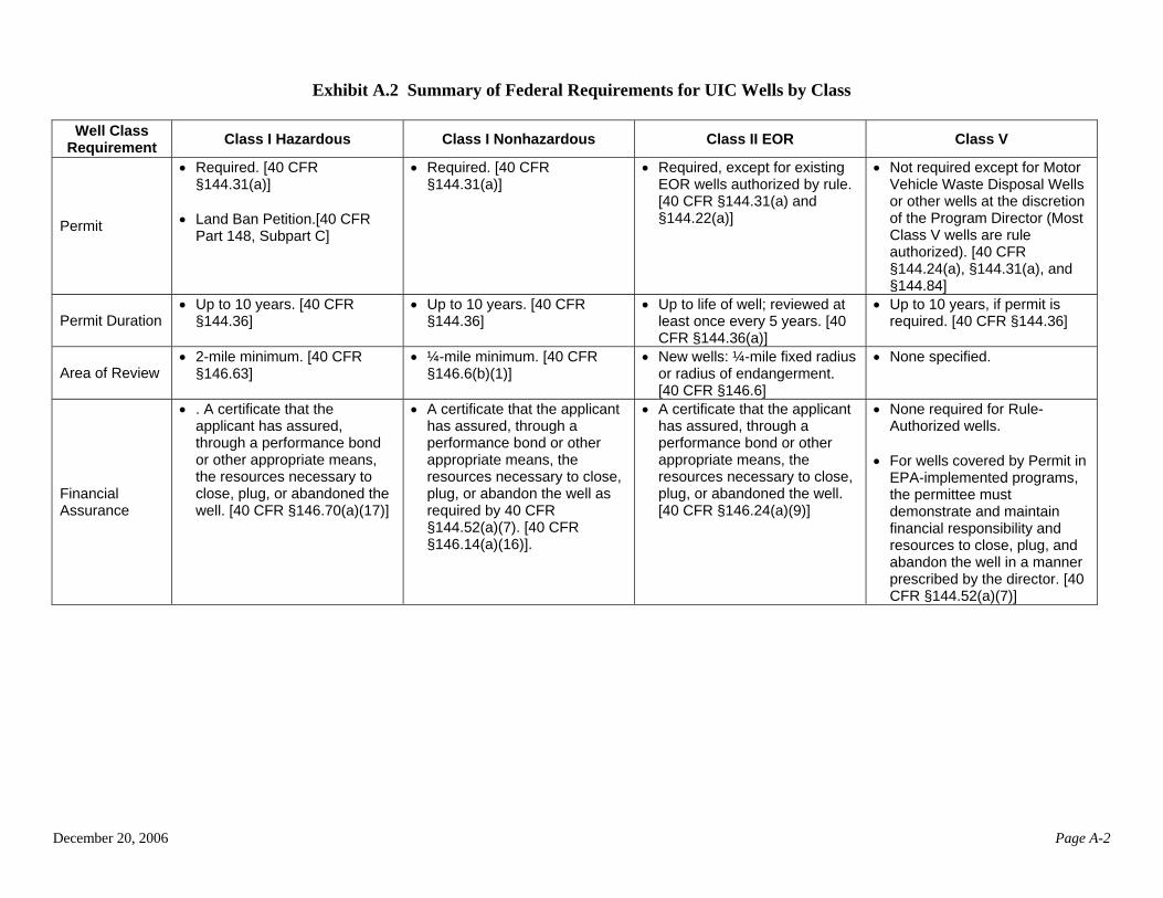
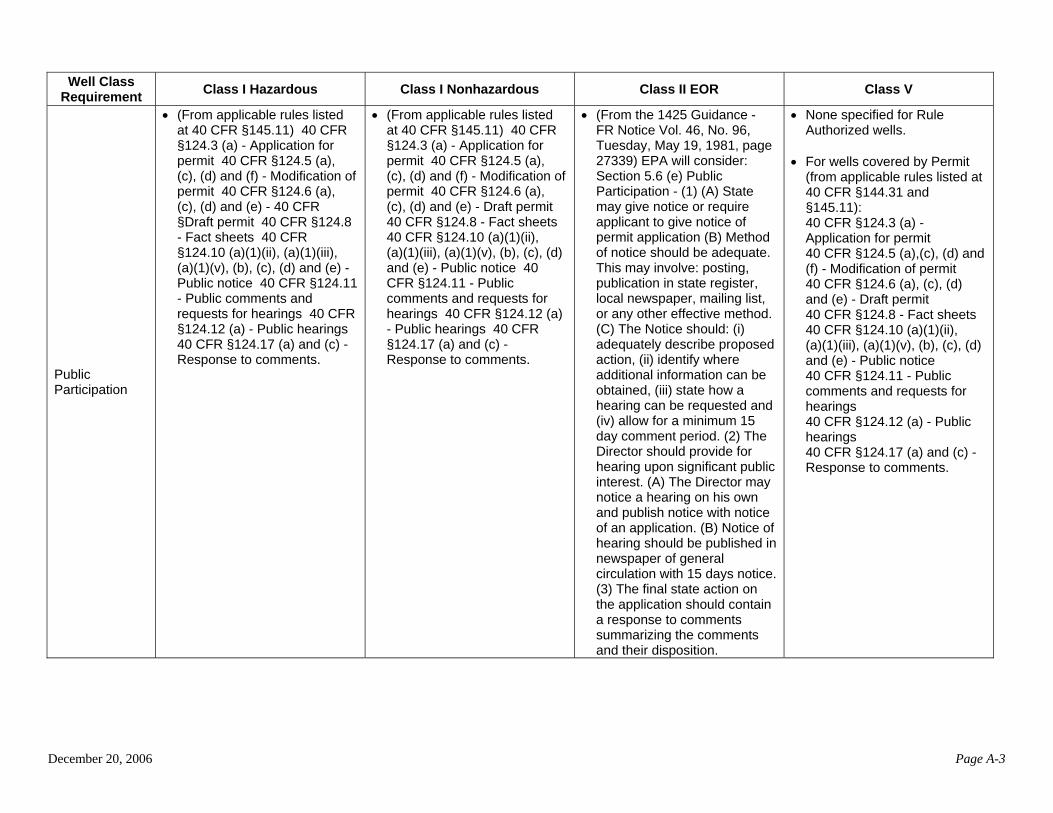
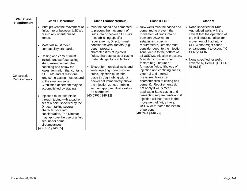
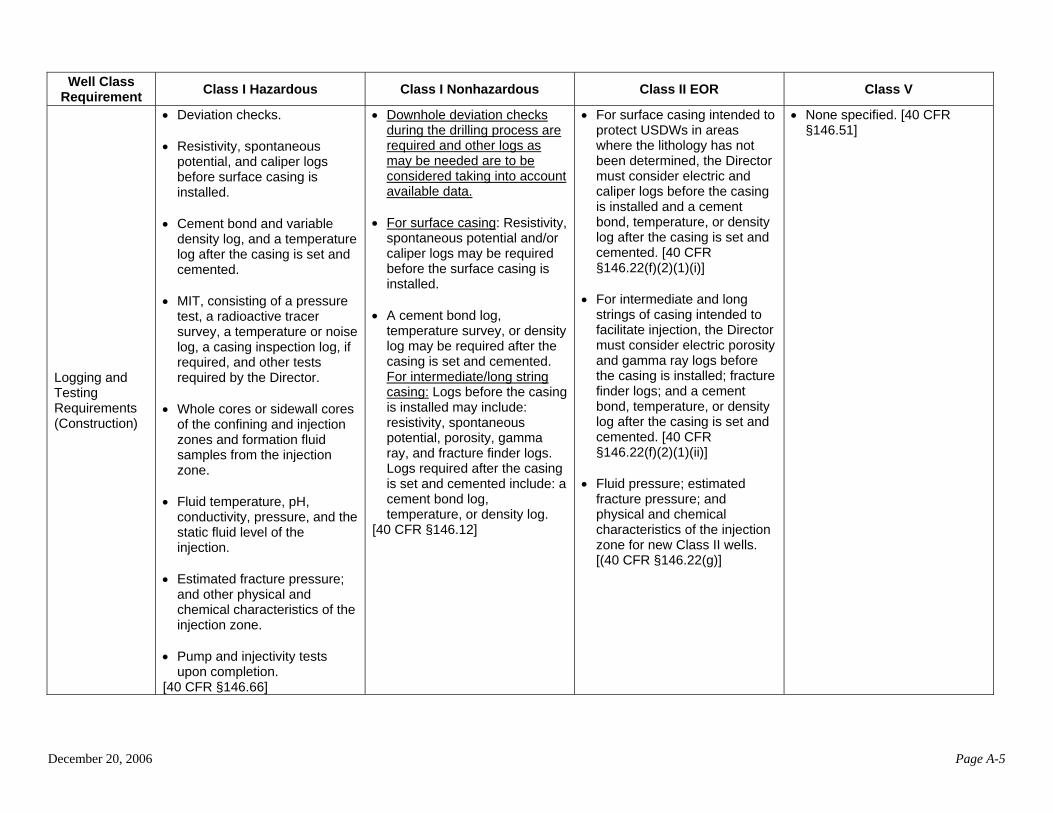
DWTR injection wells. Exhibit A.1 (in Appendix A) lists the five well classes and summarizes the viability and considerations for each well class as an option for DWTR disposal. The current viable options include Class I hazardous and nonhazardous waste injection wells, Class II enhanced oil recovery (EOR) injection wells, and Class V injection wells. UIC regulations establish minimum requirements for each well class to ensure that they do not endanger USDWs (40 CFR §144.12).
Class I wells inject industrial fluids or municipal wastewater beneath the lowermost USDW.
Class I injection wells are designated as hazardous or nonhazardous, depending on the type of fluids injected. (Fluids are considered to be hazardous wastes if they demonstrate a hazardous characteristic of ignitability, corrosivity, reactivity, or toxicity, or are a listed waste as determined by EPA. It is unlikely that the majority of DWTR would be considered hazardous, but hazardous waste disposal wells are nevertheless an option.) The fluids injected into Class I injection wells are typically associated with industries such as the chemical products, petroleum refining, and metal products industries.
Another option for DWTR disposal is injection in oil fields to enhance oil recovery where
formation pressures have been greatly lowered due to past oil production. EPA classifies such wells as Class II EOR wells (sometimes called Class II-R wells). The recovered fluid is treated to remove most of the hydrocarbons from the mineralized water in a device called a separator. Class II EOR wells then inject the mineralized water back into the formation from where it was produced (usually below the lowermost USDW) and must follow strict construction and conversion standards except when historical practices in the state and geology allow for different standards. A Class II EOR well that follows the minimum EPA requirements is built very much the same as a Class I injection well.
The use of Class V injection wells may also be an option for DWTR disposal. Many Class V
injection wells are shallow wells that inject into or above USDWs, while others, such as spent brine return flow wells, are deep wells that inject below the lowermost USDW. Meeting the non-endangerment standard may be difficult for DWTR injection wells that inject into or above a USDW. In addition, Class V injection wells are not an option for hazardous waste disposal.
Class II disposal wells (Class II-D), 3 Class II hydrocarbon storage wells (Class II-H), Class III
wells, and Class IV wells are not among the existing options for DWTR injection wells. Class II-D wells are limited to the disposal of fluids associated with natural gas storage operations, or conventional oil or natural gas production, and Class II-H wells are used for the storage of liquid hydrocarbons. Class III wells are, by definition, used solely for the injection of fluids to enhance mineral extraction. They
3 Class II-D wells could be dually permitted with either an additional Class I or Class V permit to enable the disposal DWTR. Class II-D permit/authorization wells cannot accept DWTR wastes without dual permitting (see UIC Program Guidance #24 for additional information).
December 20, 2006 Page 10
are not disposal wells. Class IV wells inject hazardous or radioactive waste into or above a USDW. They are banned except for limited ground water remediation activities.
December 20, 2006 Page 11
3.0 FEDERAL REQUIREMENTS FOR INJECTION WELLS
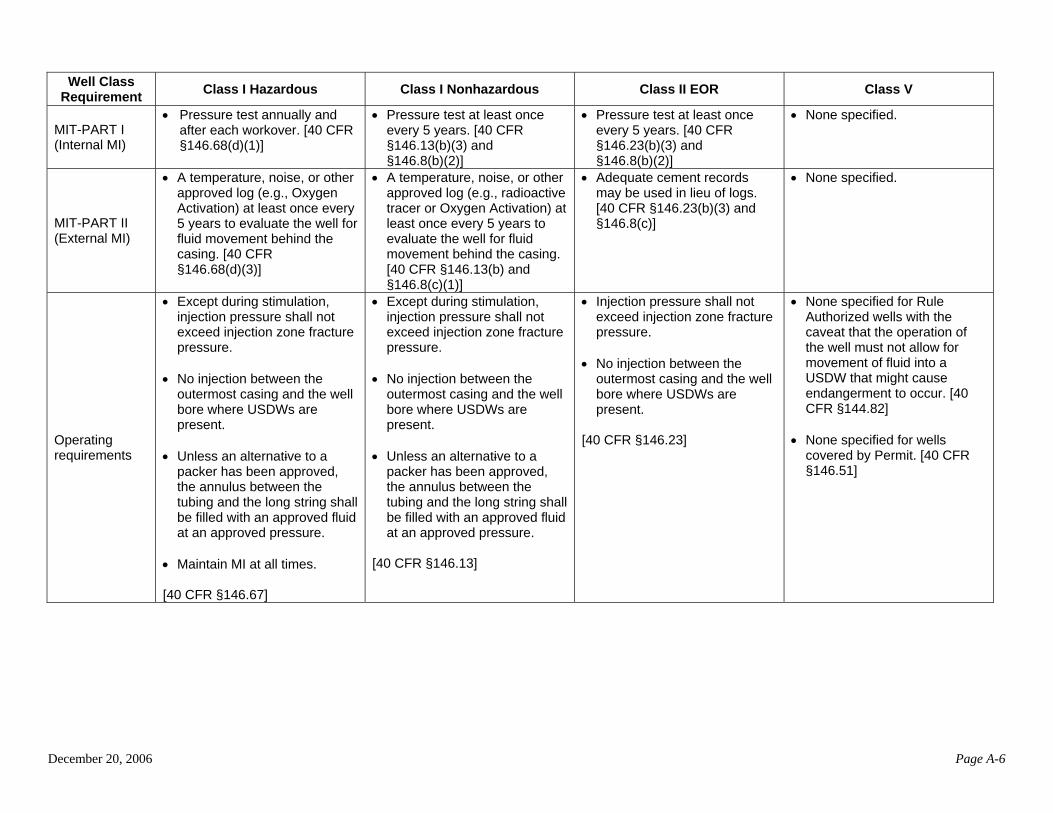
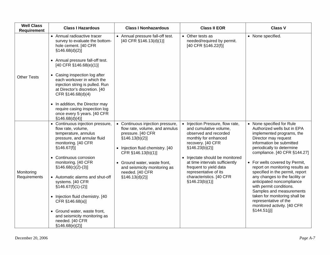
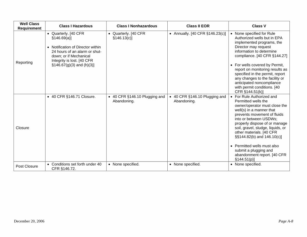
The Federal UIC regulations, as promulgated under the authorities of the Safe Drinking Water Act (SDWA), are designed to ensure that injection wells are constructed, operated, maintained, and closed in a manner that protects USDWs and public health. This section describes how the National UIC Program requirements apply to injection wells that are options for DWTR disposal—Class I hazardous and nonhazardous waste disposal wells, Class II EOR wells, and Class V injection wells. Exhibit A.2 (Appendix A) summarizes these requirements.
It should be noted that this section describes the Federal requirements. Primacy states may
impose more stringent requirements. (See, for example, Section 4 of this paper that describes state requirements for a sample of DWTR injection well permits.) 3.1 Federal Requirements for Class I Hazardous and Nonhazardous Waste Disposal Wells
EPA’s siting, construction, operating, testing, monitoring, and closure requirements for Class I injection wells provide multiple safeguards against well leakage or the movement of injected wastewater into USDWs to prevent endangerment. Class I injection wells are designated as hazardous or nonhazardous, depending on the type of the wastewaters injected. (In most cases DWTR are likely to be considered nonhazardous.) According to the Federal UIC regulations (40 CFR Part 146), Class I injection wells must be sited in geologically suitable areas, and operators must submit detailed geologic data, including maps, cross-sections, and schematics of the injection and confining zones, to demonstrate that the well is properly sited. Operators must also conduct an intensive Area of Review (AOR) study to demonstrate that there are no wells or other penetrations which could serve as conduits for injected wastes to move out of the intended injection zone within a certain distance around the well (This distance is at least a 2-mile radius for hazardous waste injection wells and at least a ¼-mile radius for nonhazardous waste injection wells). If penetrations which might allow migration due to inadequate plugging or construction are found within the AOR, the well operator must take the necessary corrective actions. In addition, Class I operators seeking to inject hazardous wastes must demonstrate via a no-migration petition that the hazardous constituents in the injected fluids will not migrate from the injection zone for as long as they remain hazardous, or 10,000 years. Federal regulations also require that Class I injection wells be constructed of materials that can withstand contact with the injected fluids, and be cased and cemented to prevent movement of fluids into USDWs. The wells must be operated in a way that is protective of USDWs. Injection pressure, flow, and volume are continuously monitored to ensure that injection pressures do not create or propagate fractures in the injection or confining formations, or cause the movement of fluids into USDWs. Pursuant to regulations, monitoring and testing of the well, injected fluids and subsurface fluids are performed periodically to verify that injection is not endangering USDWs. Continuous monitoring of pressures within the well system (annulus pressure) can provide an early warning of a breakdown in the well materials. Every 5 years (annually for hazardous wells), operators must also demonstrate internal mechanical integrity (MI) (i.e., the absence of significant leaks in the well’s casing, tubing, or packer) and external MI (i.e., the absence of significant fluid movement into USDWs through vertical channels adjacent to the wellbore). As part of the external MI demonstration for hazardous waste wells,
December 20, 2006 Page 12
operators must also check the bottom hole cement annually to ensure that it has not degraded. Operators must conduct annual ambient monitoring, and monitor injected fluids as outlined in the operating permit. All of this information must be reported to permitting authorities. Class I wells must be equipped with continuous monitoring and recording devices. For Class I hazardous wells these continuous monitoring systems must automatically sound alarms whenever operating parameters exceed permitted ranges. If a trained operator is not on-site at all times a Class I hazardous well must also have an automatic shut-off system in place should an alarm sound. Upon completion of injection operations, Class I injection wells must be plugged with cement to prevent movement of fluids out of the injection zone and into or between USDWs. Following the plugging, operators must submit a plugging and abandonment report to the permitting authority. 3.2 Federal Requirements for Class II EOR Wells
Section 1425 of the SDWA addresses injection wells associated with oil and gas production. Unlike Section 1422, which has specific requirements, Section 1425 allows states seeking primary enforcement authority under that section to demonstrate that they have programs that are protective of USDWs in lieu of adopting specific requirements. Therefore, state program requirements for Class II EOR wells may differ from the Federal program requirements discussed below.
Federal regulations require that the well adequately confine injected fluids to the authorized
injection zone to prevent the migration of fluids into USDWs. AOR evaluations are required for new Class II EOR wells (based on a ¼-mile radius or on the “radius of endangerment”). The injection wells are drilled and constructed using the same techniques as those for Class I injection wells, with steel pipe cemented in place to prevent the migration of fluids into or between USDWs. The overall well system for injection is then evaluated to make sure all the components are properly constructed.
In addition, Federal regulations require operators of Class II EOR wells to evaluate the conditions of the various well components before injection begins and once every 5 years thereafter. This includes internal MI testing similar to the testing required for Class I injection wells; however, for Class II EOR wells, cement logs or cementing records can be used to meet external MI testing requirements.
3.3 Federal Requirements for Class V Injection wells
The Federal requirements for Class V injection wells are typically less specific when compared to other well classes. UIC Program Directors have flexibility in determining the appropriate requirements for Class V injection wells on a case-by-case basis and may require the operator to obtain a permit when the injection activity warrants. In some cases, the permit’s construction, operation, and monitoring requirements might be similar to the requirements that apply to Class I or Class II EOR wells. While most individual types of Class V injection wells are not governed by specific construction or operating requirements, 40 CFR §144.51 contains general conditions applicable to all permits. These are summarized below.
• Operators must properly operate and maintain the well to achieve compliance with permit conditions. The regulations describe “proper operation and maintenance” to include effective performance, adequate funding, adequate operator staffing and training,
December 20, 2006 Page 13
adequate laboratory and process controls including appropriate quality assurance procedures. Back-up or auxiliary systems are required when needed to achieve compliance with the permit.
• Mechanical Integrity Tests (MITs) are not required to be performed for Class V injection
wells in general, as many Class V injection wells are shallow and constructed in a manner that is not amenable to such testing; however, permitting authorities have discretion in determining what type of testing is appropriate, and may require MITs of certain injection wells. In fact, a review of existing DWTR permits and authorizations reveals Class V DWTR injection well authorizations include MIT conditions (see Section 4). In addition, operators may be required to take samples and measurements that are representative of the monitored activity. This could include monitoring of injection parameters (e.g., pressures or volumes) or chemical monitoring of the injectate.
• Class V injection wells must be closed in a manner that prevents the movement of fluids
into or between USDWs. Operators must also properly dispose of or manage soil, gravel, sludge, liquids, or other materials near the well in accordance with all Federal, state, and local regulations.
In addition to the permitting requirements outlined above, Class V injection wells cannot accept
hazardous waste. Hazardous wastes are defined by regulations implemented under the Resource Conservation and Recovery Act. Hazardous waste includes both listed wastes (which are described in Subpart D of 40 CFR Part 261), and characteristically hazardous wastes (i.e., wastes that exhibit any or all of the four characteristics of hazardous wastes – ignitability, corrosivity, reactivity, and toxicity – described in Subpart C of 40 CFR Part 261).
Furthermore, the fluids injected into a Class V injection well (or any other class of injection
well) cannot endanger a USDW as defined at 40 CFR §144.12. This section prohibits the operation of an injection well that allows the movement of a fluid containing any contaminant into a USDW where the presence of that contaminant would cause a violation of a primary drinking water regulation or would otherwise adversely affect public health. The determination of endangerment is typically made on a case-by-case basis taking site-specific conditions into consideration. The NTW is deferring discussion of “endangerment” to UIC program managers because they are considering the legal and policy issues associated with DWTR injection. As discussed in Section 1.2, these legal and policy issues are outside the scope of this NTW technical paper.
December 20, 2006 Page 14
4.0 OVERVIEW OF CURRENT DWTR MANAGEMENT PRACTICES IN REGIONS, STATES, AND TERRITORIES
The NTW subgroup collected information on current practices regarding DWTR injection wells.
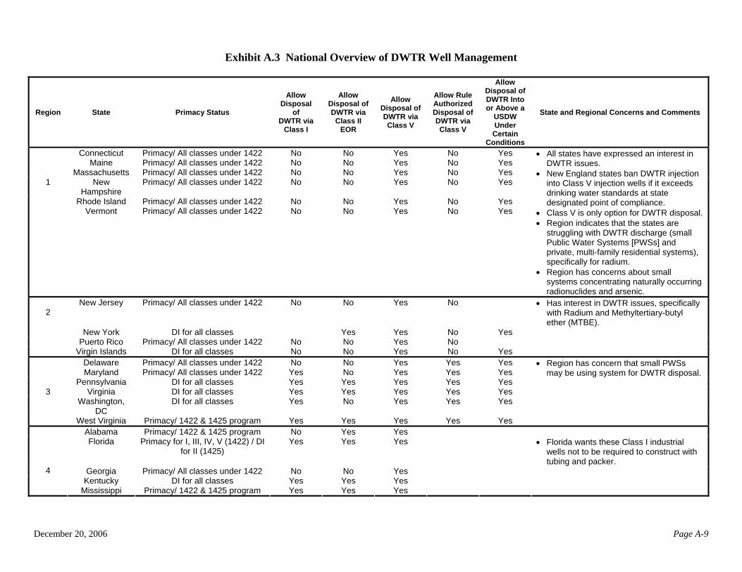
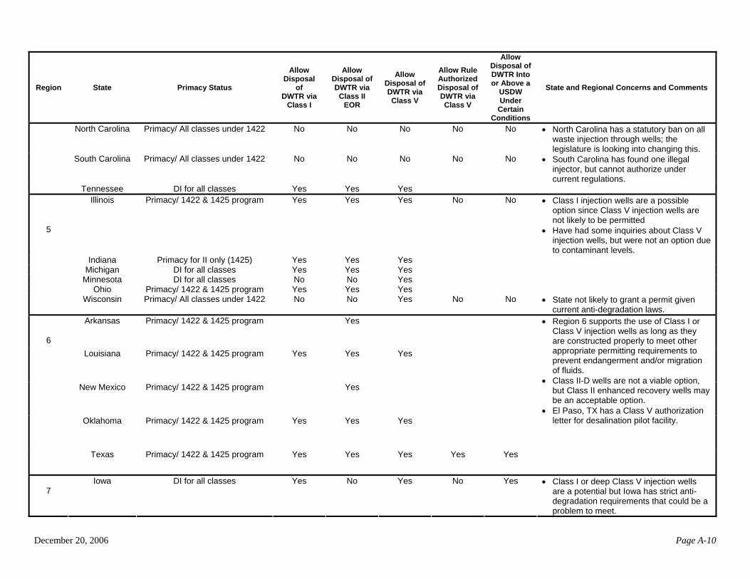
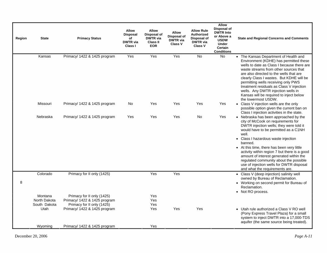
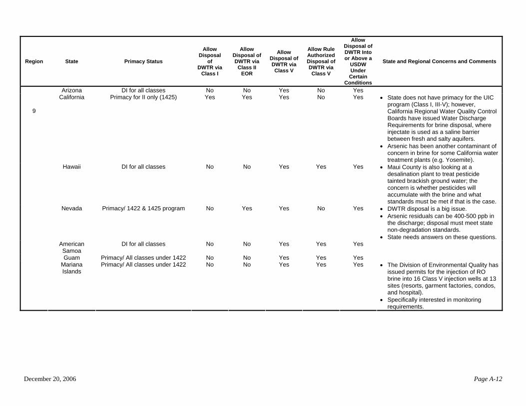
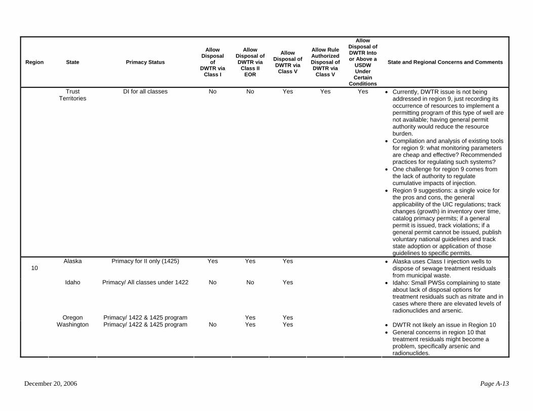
The subgroup surveyed all EPA Regions to determine which regions, states, and territories have authorized DWTR injection wells, how permitted or authorized wells are classified, and what requirements are being applied to DWTR injection wells. The subgroup also collected information on the availability of Class I, II EOR, and V injection wells as disposal options for DWTR throughout the country. This section summarizes the information collected as a result this survey. Specifically, Section 4.1 provides background on which states have primary enforcement authority for each well class, Section 4.2 summarizes the number of existing DWTR injection wells and discusses the potential for DWTR injection wells, and Section 4.3 summarizes DWTR injection well requirements in a sample of existing permits. A more detailed description of some of the survey results can be found in Appendix A (Exhibit A.3). 4.1 DWTR Disposal Options in Primacy and Direct Implementation States
EPA has granted primary enforcement authority (“primacy”) over injection wells to states that
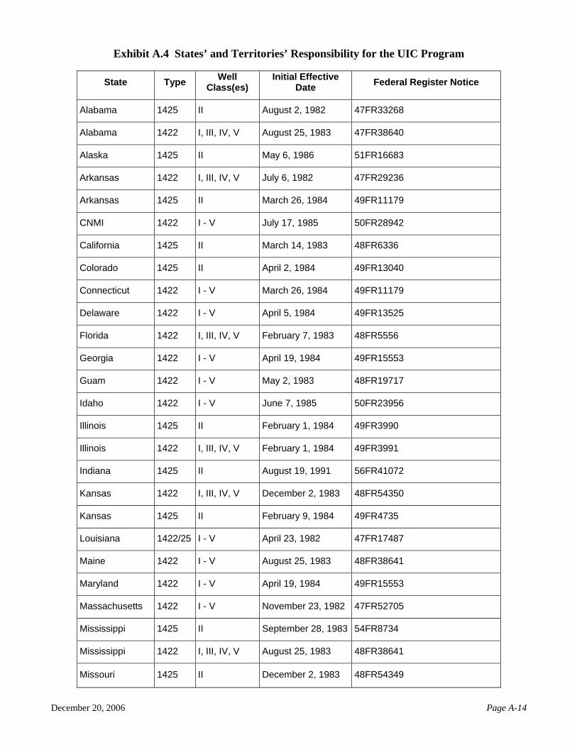
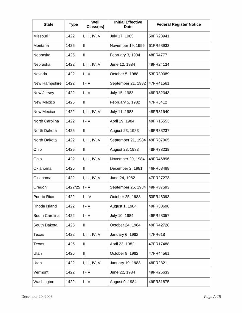
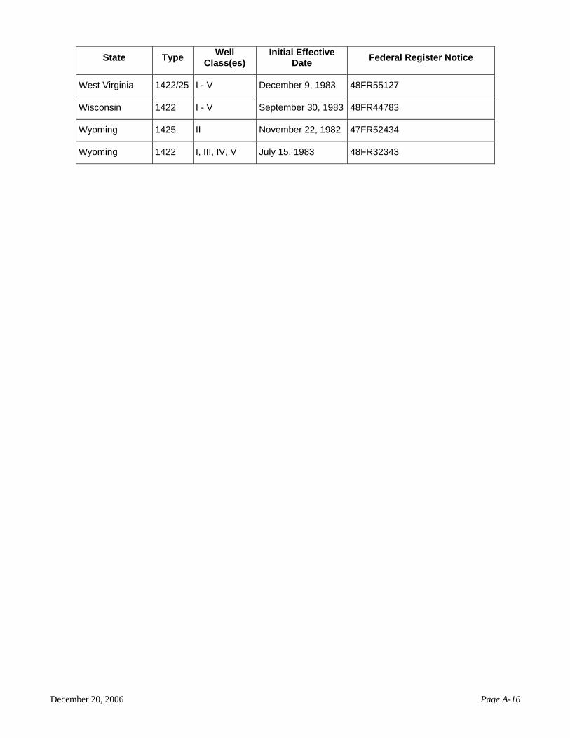
have demonstrated that they meet the UIC requirements contained in Sections 1422 and 1425 of the SDWA and in the Federal regulations (40 CFR Parts 144 – 147). Of the 57 states (and territories),4 36 have primacy over all classes of injection wells. In states that have not received primacy, EPA remains the responsible regulatory agency. These programs are referred to as Direct Implementation (DI) programs. In 14 states and all tribal lands, EPA directly implements the UIC program for all classes of injection wells. The remaining seven states share responsibility with EPA—the state has primacy over some wells classes, while EPA oversees the regulations of other classes. A list of the states’ and territories’ responsibility for the UIC program can be found in Appendix A (Exhibit A.4). 4.2 Existing DWTR Injection Wells and Available Options for DWTR Injection
States and regions report that they have permitted or authorized a total of 101 DWTR injection wells. Florida has the highest number (75) of DWTR injection wells, followed by the Commonwealth of the Northern Mariana Islands (CNMI) (16). Other states with DWTR injection wells include Texas, Kansas, Utah, and Hawaii.
Of the 101 injection wells, the majority (63) are Class I nonhazardous injection wells. There are
38 Class V injection wells; 31 have been permitted, and 7 have been rule-authorized. The rule-authorized wells include five Class V injection wells in El Paso (under one operation, for a desalination pilot facility), one Class V DWTR injection well in Utah, and one in Hawaii. The NTW is not aware of any Class II EOR injection wells that are receiving DWTR.
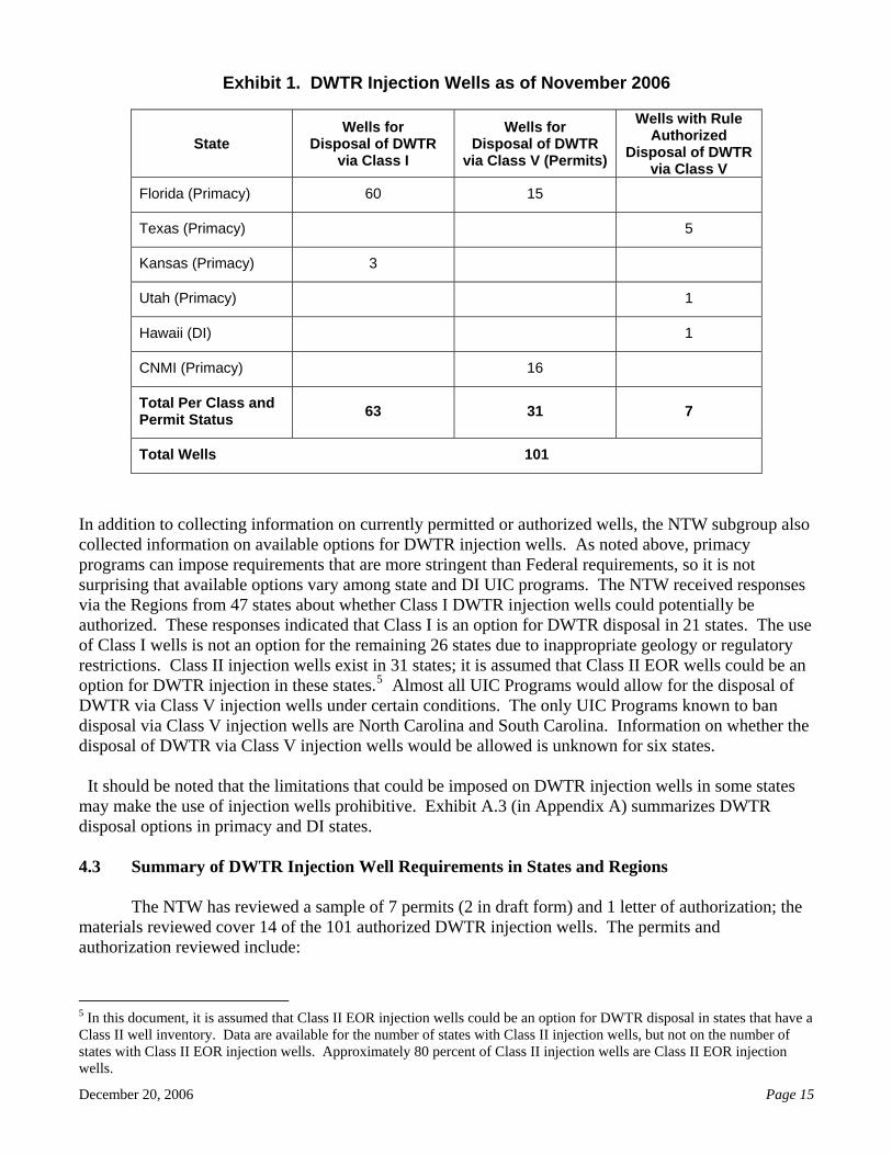
Exhibit 1 summarizes the number of DWTR injection wells by state.
4 In this document, the term state includes all the 50 states, territories, and the District of Columbia.
December 20, 2006 Page 15
Exhibit 1. DWTR Injection Wells as of November 2006
State Wells for
Disposal of DWTR via Class I
Wells for Disposal of DWTR
via Class V (Permits)
Wells with Rule Authorized
Disposal of DWTR via Class V
Florida (Primacy) 60 15
Texas (Primacy) 5
Kansas (Primacy) 3
Utah (Primacy) 1
Hawaii (DI) 1
CNMI (Primacy) 16
Total Per Class and Permit Status 63 31 7
Total Wells 101
In addition to collecting information on currently permitted or authorized wells, the NTW subgroup also collected information on available options for DWTR injection wells. As noted above, primacy programs can impose requirements that are more stringent than Federal requirements, so it is not surprising that available options vary among state and DI UIC programs. The NTW received responses via the Regions from 47 states about whether Class I DWTR injection wells could potentially be authorized. These responses indicated that Class I is an option for DWTR disposal in 21 states. The use of Class I wells is not an option for the remaining 26 states due to inappropriate geology or regulatory restrictions. Class II injection wells exist in 31 states; it is assumed that Class II EOR wells could be an option for DWTR injection in these states.5 Almost all UIC Programs would allow for the disposal of DWTR via Class V injection wells under certain conditions. The only UIC Programs known to ban disposal via Class V injection wells are North Carolina and South Carolina. Information on whether the disposal of DWTR via Class V injection wells would be allowed is unknown for six states.
It should be noted that the limitations that could be imposed on DWTR injection wells in some states may make the use of injection wells prohibitive. Exhibit A.3 (in Appendix A) summarizes DWTR disposal options in primacy and DI states. 4.3 Summary of DWTR Injection Well Requirements in States and Regions
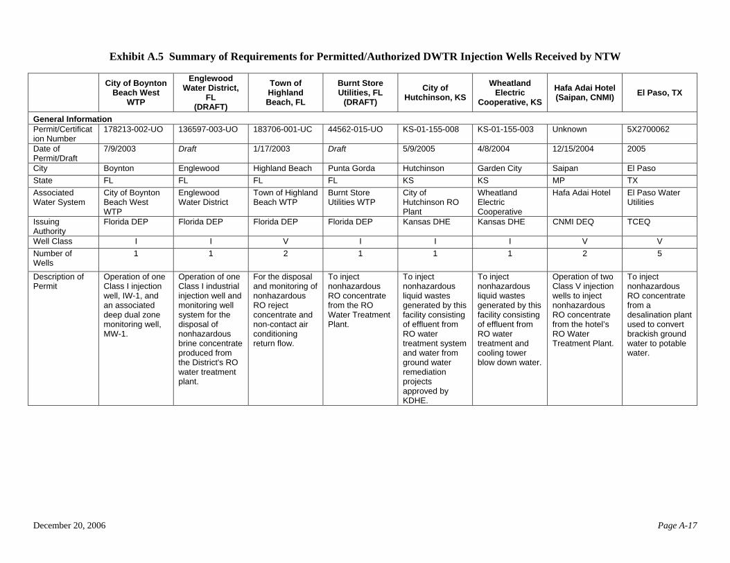
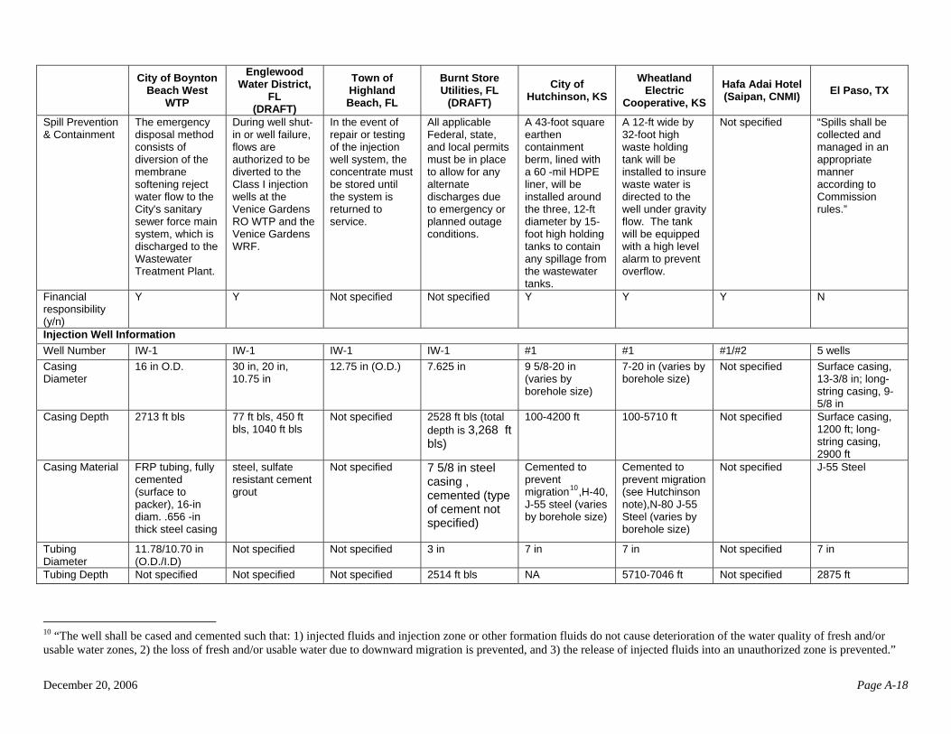
The NTW has reviewed a sample of 7 permits (2 in draft form) and 1 letter of authorization; the materials reviewed cover 14 of the 101 authorized DWTR injection wells. The permits and authorization reviewed include:
5 In this document, it is assumed that Class II EOR injection wells could be an option for DWTR disposal in states that have a Class II well inventory. Data are available for the number of states with Class II injection wells, but not on the number of states with Class II EOR injection wells. Approximately 80 percent of Class II injection wells are Class II EOR injection wells.
December 20, 2006 Page 16
• Three Florida permits (two in draft form) covering three Class I nonhazardous waste disposal wells.
• One Florida permit covering two Class V injection wells. • Two Kansas permits covering two Class I nonhazardous waste disposal wells. • One CNMI permit covering two DWTR injection wells. Although the well classes are not
specified in this permit, NTW information confirms they are Class V injection wells. • One letter of authorization issued by Texas (covering five Class V injection wells under a
single operator in El Paso). In aggregate, the materials reviewed address five Class I nonhazardous waste disposal wells and
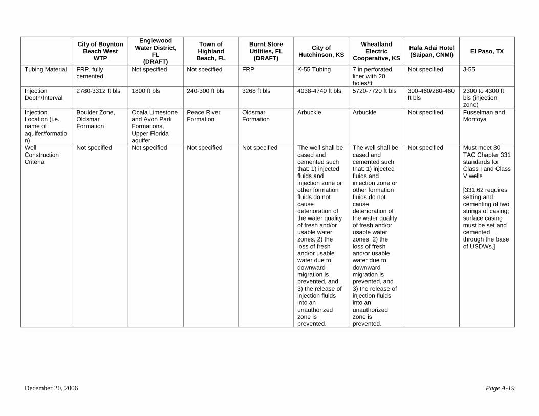
nine Class V injection wells. The requirements for the Class V injection wells generally appear to be as comprehensive as the requirements for the Class I injection wells. The seven permits and the letter of authorization were collected and reviewed, and information on the wells, construction criteria, and monitoring and testing criteria were tabulated. Some details about the El Paso wells are not contained in the authorization letter and were obtained from other sources (additional information on these wells may be available from still other sources). Exhibit A.5 (Appendix A) summarizes the requirements applicable to each operator. Well Construction The Class I DWTR wells inject to depths ranging from 1,800 to 5,710 feet below ground surface. All Class I injection wells are encased in steel (e.g., J-55 steel), with casing diameters ranging from 7 to 30 inches. All of the Florida Class I DWTR injection well permits examined stated that the wells were “fully cemented.” In specific cases, Type II (Class H) sulfate-resistant cement was required to ensure integrity of the wells. Kansas requires Class I DWTR injection wells to be cemented in such a way that 1) injected fluids and injection zone or other formation fluids do not cause deterioration of the water quality of fresh and/or usable water zones, 2) the loss of fresh and/or usable water due to downward migration is prevented, and 3) the release of injected fluids into an unauthorized zone is prevented. Specific cement requirements for the entire depth of the wells were listed in the permits (e.g., cement grades and numbers of sacks of cement at various stages of cementing).
Tubing diameters for the Class I injection wells range from approximately 3 to 12 inches, and tubing materials identified include fiberglass-reinforced plastic, K-55 steel, and J-55 steel tubing. In addition, mild steel, epoxy-coated steel, acrylonitrile-butadiene-styrene (ABS), and duplex stainless steel are considered to be appropriate tubing materials in Florida for DWTR injection wells; although there are concerns regarding the corrosion of unprotected mild steel by RO concentrates
Packers are required for all reviewed Class I DWTR injection wells. In Florida, mechanically
set, conventional packers are used. These packers are designed to be removable, and they provide a positive seal for the annulus. In some cases, after a leak developed in the annulus, cementing of the entire annulus was allowed by Florida. For the two Class I injection wells in Kansas, specific packers (TAM packer with seal bore and Brown Liner Hanger set in compression) were listed in the permits.
December 20, 2006 Page 17
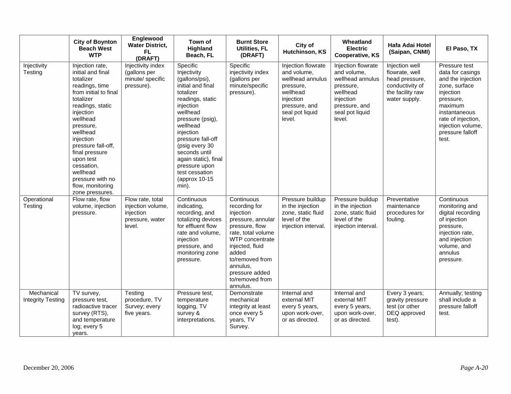
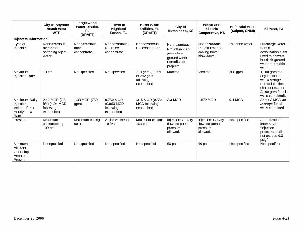
Based on the reviewed permits, Class V injection wells inject to depths ranging from 240 to 4,300 feet. Apart from the proposed wells of El Paso Water Utilities, casing materials for the Class V injection wells are not specified in the permits or letter of authorization, nor are the tubing materials and most diameters. The casing diameter for the Class V injection well of Highland Beach, Florida is cited as 12-3/4 inches and those for the El Paso wells as 13-3/8 inches for surface casing and 9-5/8 inches for long-string casing. It should be noted that the Class V El Paso wells are constructed to Texas’ Class I well standards. The surface casings for the El Paso wells are set to 1,200 feet and the long-string casings to 2,900 feet. All casings are cemented from the bottom of the borehole to the land surface. J-55 steel is used for both casing and tubing. A 9-5/8 inch by 7 inch tension-set, retrievable packer is specified and the resulting annulus will be filled with fresh water containing corrosion inhibitor and oxygen scavenger. Kansas has indicated that wells receiving only DWTR wastes would be permitted as Class V wells and built to the same standards as the Class I wells that have been mentioned earlier in the report. Well Operation and Monitoring /Testing All of the permits specify a maximum daily injection volume [from 0.3 to 2.4 million gals/day (MGD)] and injection pressure. The El Paso well authorization does not specify daily maximum injection rates, but specifies monthly and annual maximums equivalent to just over 3.0 MGD for the facility’s five wells. All operators must monitor injection flow rate, volume, and pressure (most permits specify continuous monitoring). Other parameters specified in some of the permits include wellhead annulus pressure (3 permits), initial and/or final totalizer reading (2 permits), and pressure fall-off testing (1 permit and 1 letter of authorization). All seven permits and the letter of authorization include MIT requirements:
• The Florida permits require MITs every 5 years; they specify various MIT methods, including TV surveys, pressure testing, radioactive tracer surveys, and temperature logging. [Three Class I injection well permits and one Class V injection well permit.]
• Kansas requires internal and external MIT every 5 years, upon work-over, or as directed
(no methods are specified). Additionally, Kansas requires annual pressure fall-off testing. [Two Class I injection well permits.]
• CNMI requires MIT every 3 years, using a method approved by CNMI DEQ. [One Class
V injection well permit.]
• Texas requires annual MIT and pressure fall-off testing for all five wells authorized for the El Paso desalination project.
December 20, 2006 Page 18
Injectate Testing All eight operators have injectate monitoring requirements (either weekly, monthly, quarterly, and/or annually). All must monitor for pH and total dissolved solids (TDS) and total suspended solids (TSS); most monitor for chloride and conductivity. Other commonly noted parameters for monitoring include temperature (the 7 permits), sulfate (the 7 permits and El Paso), sodium (5 of the permits), and Total Kjehldahl Nitrogen (TKN) or nitrogen (4 of the permits). Most of the Florida permits and the El Paso rule-authorization require monitoring of gross alpha or Radium-226 and Radium-228; two Florida wells are required to monitor for all primary and secondary drinking water standards; El Paso must monitor for all inorganic constituents with state-defined Maximum Contaminant Levels (MCLs), constituents with secondary drinking water standards, and radioactive constituents listed in the state regulations. Florida requires monitoring wells in a transmissive zone above and below the injection zone for all the permits examined, including Class V wells. No other permits examined mentioned specific requirements for monitoring wells.
December 20, 2006 Page 19
5.0 CHEMICAL CHARACTERISTICS AND VOLUME OF DWTR WASTESTREAMS 5.1 Contaminants of Concern and Potential Impacts
Contaminants concentrated in DWTR include metals (e.g., arsenic and selenium), radionuclides (e.g., radium 226/228), nitrates, and salts. The treatment goal (e.g., desalination and removal of arsenic), treatment process employed (e.g., RO and ion exchange), and chemical characteristics of the raw source water all have effects on the chemical characteristics of DWTR generated in the production of finished water.
Solid DWTR, which are disposed of in landfills and through land applications, are comprised of
dewatered slurry and sludge from coagulation (e.g., alum and ferric sludge), lime softening, and spent media (i.e., for ion exchange). These types of DWTR waste streams are not covered in this report.
Liquid DWTR, which can be disposed of through injection wells, are generally characterized by
high concentrations of TDS and TSS; for example, TDS concentrations resulting from the desalination of brackish ground water can be as high as 40,000 mg/L.6 The volume of liquid DWTR generated is related to the flow rate of the treatment plant and, in some cases, the recovery rate or efficiency of the treatment process, the frequency of backwashing, and other operational factors. In addition to high TDS and TSS concentrations, DWTR may have any of the following characteristics that present specific management and disposal challenges:
• High or low pH • High concentrations of heavy metals (e.g., arsenic, lead, and aluminum) • High fluoride, sodium, chloride, and other salt concentrations • Radionuclides and daughter products in significant concentrations7
Under Federal regulations (40 CFR §144.12), injection operations may not cause the movement
of fluids that contain contaminants that may cause a violation of any primary drinking water regulation or otherwise adversely affect public health into USDWs. In addition, movement of DWTR into USDWs may cause violations of state ground water quality standards or ground water antidegradation standards. Injection below all USDWs or into a USDW with similar characteristics to the DWTR (usually this will be the lowermost USDW) is expected to mitigate the potential for movement of DWTR outside of the intended injection zone or cause a violation of 40 CFR §144.12. (Due to high TDS levels, DWTR are not typically buoyant and therefore are not expected to migrate upward unless increased pressure due to injection and/or reduced pressure due to pumping from a USDW causes a pressure imbalance.)
In addition, there are concerns about geochemical interactions between the concentrate and the native formation water or the lithology of the receiving formation. Silica, gypsum, and calcite can precipitate and reduce the permeability of the receiving formation. In addition, fines, colloidal material, iron corrosion products, and clay can all have a negative impact on the injection well and receiving formation.8
6 AWWA 2004. 7 Under the Federal UIC regulations, “radioactive” refers to any waste containing radioactive concentrations that exceed those listed in 10 CFR Part 20, Appendix B, Table II, Column 2. These concentrations are 60 pCi/L for radium-226, 60 pCi/L for radium-228, and 300 pCi/L for uranium. Additional criteria apply if more than one radionuclide is present. Demonstration of the non-endangerment standard will be difficult for shallow injection of radioactive DWTR. 8 Fubryka-Martin 2006.
December 20, 2006 Page 20
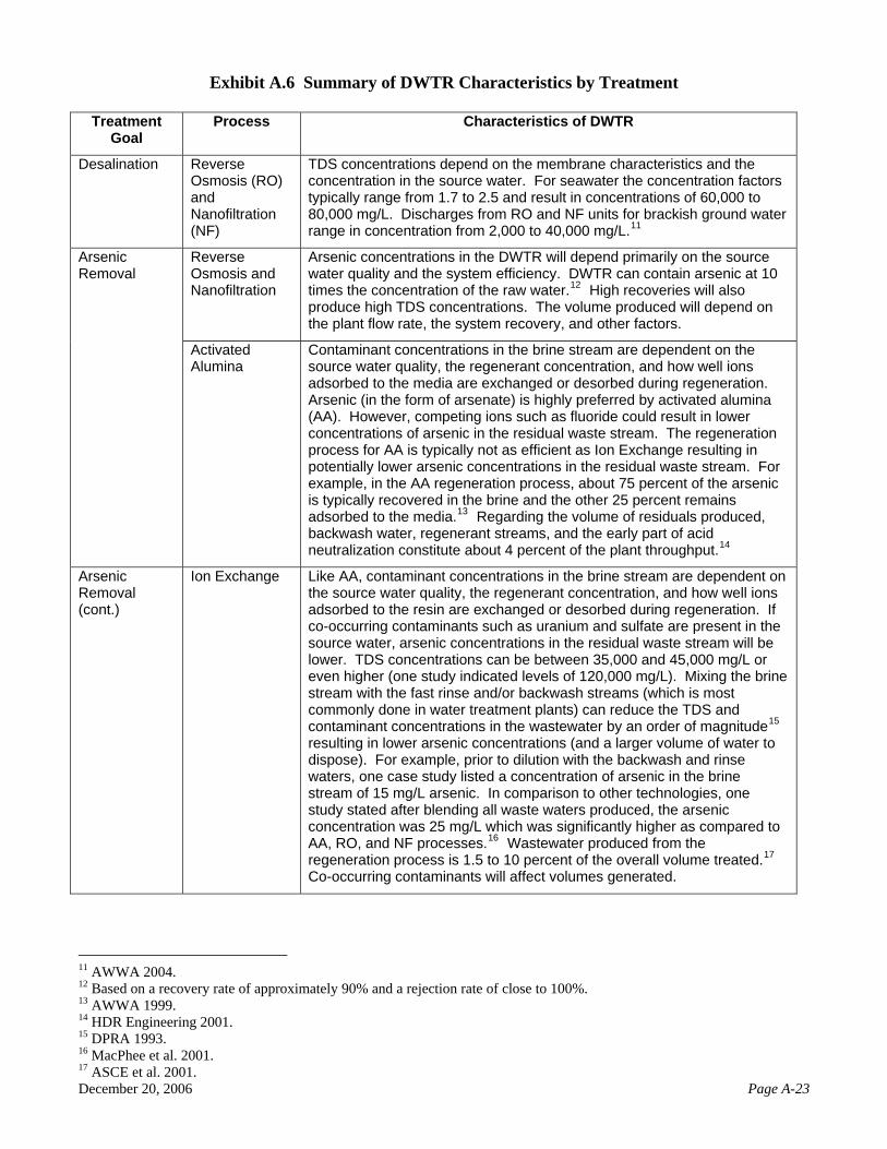
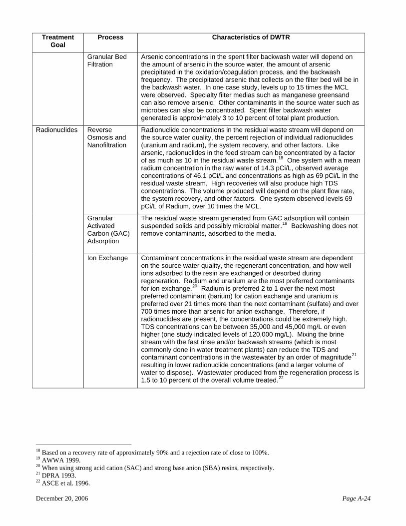
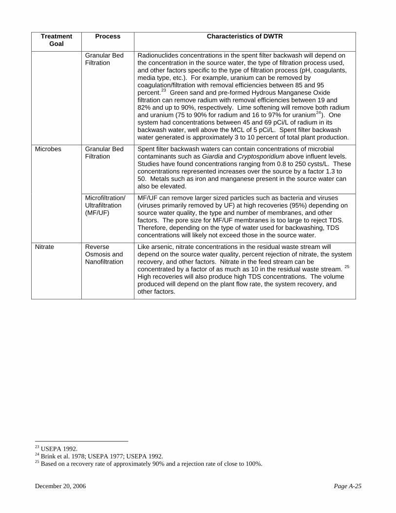
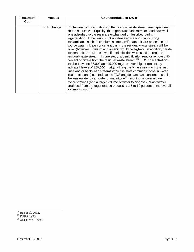
Exhibit A.6 (Appendix A) summarizes the characteristics of liquid residuals by treatment goal
and treatment process. It draws examples from published studies that demonstrate the types of contaminants and concentrations which may be found in DWTR. Appendix B provides a more detailed description of each process and outlines the factors which will determine the characteristics and volumes of the DWTR produced. 5.2 Volume of DWTR Fluids
The volume of liquid DWTR depends on raw water quality, dosage of any chemicals used, type of treatment process, performance of the treatment process, and operational procedure of the water treatment plants. Volumes associated with filter backwashing of granular bed filtration are about 1 to 3 percent of the total processed raw water. Volumes of ion exchange fluid DWTR (i.e., brine, backwash, and rinse waters) range from 1.5 to 10 percent of the overall volume treated. Based on Min et al. (2005), the volume of brine produced at ion exchange drinking water treatment facilities can be up to 250,000 gallon per day (gpd) for a 12.96 MGD plant. Activated alumina brine, backwash, and rinse waters constitute about 4 percent of the plant throughput (HDR Engineering, 2001). Dewatering of sludge from coagulation and lime softening, and backwashing of granular activated carbon, both generate very small volumes of liquid residuals.
Membrane technologies (RO, NF, MF, and UF) generate a larger proportion of reject water, compared to the volume of total treated water. Volumes can range from 5 to 40 percent of the total treated water, depending on the process and water quality. In addition, membrane technologies are likely to be selected to handle large treatment volumes. For example, the RO water treatment system of the City of Hutchinson, Kansas generates about 2 MGD of reject water. Other facilities with similar volumes of DWTR fluid include City of Boynton Beach West Water Treatment Plant, Florida (with a maximum daily injection volume of 2.4 MGD); Englewood Water District, Florida (1.08 MGD); Wheatland Electric Cooperative, Kansas (1.872 MGD); and the proposed El Paso Joint Desalination Facility (3 MGD). Smaller RO facilities include the Burnt Store Utilities, Florida (0.315 MGD); Hafa Adai Hotel, Saipan (0.4 MGD); and Town of Highland Beach, Florida (0.75 MGD). 5.3 Summary of DWTR Characteristics The NTW has reviewed literature and permit information relating to various off-the-shelf treatment technologies that generate liquid DWTR. Based on the reviewed information, the various treatments can produce DWTR that contain targeted contaminants at 10 times the concentration of the raw water source. Further observations include:
• Removal of arsenic by RO and nanofiltration, activated alumina, ion exchange, and granular bed filtration can produce concentrates with arsenic concentration that exceed the MCL (e.g., up to 15 times).
• Treatment of radionuclides by RO and nanofiltration, GAC adsorption, ion exchange, and
granular bed filtration can generate concentrates with radium at concentrations that are 10 times the MCL.
• Filtration of microbes (e.g., Giardia and Cryptosporidium) using granular bed filtration
and microfiltration/ultrafiltration is associated with an increase of microbe concentrations by a factor of up to 50.
December 20, 2006 Page 21
• Removal of nitrate using RO and nanofiltration can produce liquid DWTR with high
TDS and nitrate. Concentrations of these constituents can be as much as 10 times greater than in the raw water.
• The volume of liquid DWTR depends on raw water quality, dosage of any chemicals
used, type of treatment process, performance of the treatment process, and operational procedure of the water treatment plants. Membrane technologies can produce much higher residual volumes than other processes. Based on design documents and permits, the volume of RO reject waters can be upward of 3 MGD.
With elevated concentrations of various contaminants and the large volumes involved, the technical workgroup believes that the injection of concentrates could potentially threaten USDWs and public health. In addition, high TDS and differing geochemistry between the native formation/formation water and the injected concentrates could lead to precipitation of minerals such as calcite, gypsum, and silica that physically and chemically affect the permeability and porosity of the receiving formation.
December 20, 2006 Page 22
6.0 COMPARISON OF DWTR CHARACTERISTICS TO FLUIDS RECEIVED BY EXISTING INJECTION WELL CLASSES
6.1 Characteristics of Fluids Received by Various Injection Well Classes
As described in Section 5, the types of chemical constituents and contaminants potentially found in DWTR are numerous and include metals, salts, dissolved organics, radionuclides, disinfection by-products, and microbials. For example, arsenic, barium, cadmium, chloride, chromium, copper, fluoride, lead, mercury, nitrate, selenium, and combined radium 226/228 have been detected in DWTR in concentrations that could cause an exceedance of Federal drinking water standards. In addition, boron, manganese, nickel, phosphorus, strontium, and zinc were detected at least once at concentrations that exceed the lifetime Health Advisory levels. Aluminum, chloride, copper, fluoride, iron, manganese, pH, sulfate, TDS, and zinc were detected at least once at levels that do not meet EPA Secondary Standards. Fluids that are typically discharged to Class I hazardous and nonhazardous injection wells, Class II wells, and Class V injection wells vary widely. Class I hazardous waste disposal wells accept fluids that are defined as hazardous under EPA’s regulations. Fluids are considered to be a hazardous waste if they demonstrate a hazardous characteristic of ignitability, corrosivity, reactivity, or toxicity, or are a listed waste deemed hazardous by EPA.
Class I nonhazardous waste disposal wells accept either industrial fluids or municipal wastes and inject them beneath the lowermost USDW within ¼ mile. Many Class I industrial wells inject fluids associated with chemical products, petroleum refining, and metal products industries. Injected fluids vary significantly based on the process from which they are derived. Class I municipal wells, located in Florida, primarily accept domestic wastewater that has undergone at least secondary wastewater treatment. The wastewater also has a small industrial component because of industries that discharge to the wastewater system. The wastewaters injected into Class I municipal wells are typically high in Biochemical Oxygen Demand (BOD), which is a measure of the amount of oxygen consumed by microorganisms during the decomposition of organic matter. These wastewaters also contain suspended solids, pathogens, nitrogen and phosphorus compounds, and small amounts of the metals and organics typical to industrial discharge (the concentration of such compounds depends largely on the industrial contribution). Class II injection wells are used to increase oil or natural gas production or to dispose of fluids generated in connection with natural gas storage operations, conventional oil or natural gas production, or the storage of liquid hydrocarbons. The characteristics and physical properties of these fluids vary considerably depending on the geographic location and geologic formation of the reservoir that generated the fluid(s), how long they have been in contact with the formation, and the type of hydrocarbon(s) that are being stored or produced. These properties and volumes can also vary throughout the lifetime of the operation. While there is variability in the composition of these fluids, certain characteristics are similar to those contained in DWTR, the most obvious being TDS. Most oil and gas producing areas in the United States have a mix of TDS values for the water produced (which is typically injected into the subsurface by Class II injection wells) in the 10,000 to 200,000 ppm range.9 While these TDS values are greater than those generated by most RO plants, they serve as a useful analog for fluids that would be injected by DWTR wells. Additionally, the fluids disposed of by Class II-D injection wells also contain suspended solids and small amounts of metals and organics, which are also typically found in DWTR waste streams.
9 U.S. Department of the Interior. Undated.
December 20, 2006 Page 23
The fluids injected in Class V injection wells vary widely and “typical” injectate characteristics
are difficult to define. They may include brines (as in the case of spent brine return flow wells), fluids that contain wastes associated with industrial processes (as in the case of industrial wells), or fluids similar to those injected into Class I municipal wells (as in the case of large-capacity septic systems or sewage disposal wells). In Arkansas and Michigan, Class V spent brine injection wells are associated with the reinjection of spent brine into the same formation from which it was withdrawn after extraction of halogens or their salts. In addition to the elevated TDS, other constituents in spent brine include sodium, calcium, magnesium, barium, iron, chloride, sulfate, carbonate, bicarbonate, and sulfide. In Arkansas, spent brine from extraction of bromine is disposed of through Class V injection wells below the lowermost USDW. Available data indicate that concentrations of barium and boron in spent brine (associated with bromine extraction) routinely exceed MCLs or Health Affect Levels. Recent data indicates that chlorinated solvents are detected in the “tail brine” associated with bromine extraction.
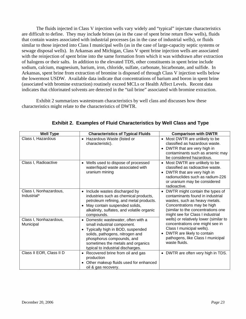
Exhibit 2 summarizes wastestream characteristics by well class and discusses how these
characteristics might relate to the characteristics of DWTR.
Exhibit 2. Examples of Fluid Characteristics by Well Class and Type
Well Type Characteristics of Typical Fluids Comparison with DWTR
Class I, Hazardous • Hazardous Waste (listed or characteristic).
• Most DWTR are unlikely to be classified as hazardous waste.
• DWTR that are very high in contaminants such as arsenic may be considered hazardous.
Class I, Radioactive • Wells used to dispose of processed water/liquid waste associated with uranium mining
• Most DWTR are unlikely to be classified as radioactive waste.
• DWTR that are very high in radionuclides such as radium-226 or uranium may be considered radioactive.
Class I, Nonhazardous, Industrial*
• Include wastes discharged by industries such as chemical products, petroleum refining, and metal products.
• May contain suspended solids, alkalinity, sulfates, and volatile organic compounds.
Class I, Nonhazardous, Municipal
• Domestic wastewater, often with a small industrial component.
• Typically high in BOD, suspended solids, pathogens, nitrogen and phosphorus compounds, and sometimes the metals and organics typical to industrial discharges.
• DWTR might contain the types of contaminants found in industrial wastes, such as heavy metals. Concentrations may be high (similar to the concentrations one might see for Class I industrial wells) or relatively lower (similar to concentrations one might see in Class I municipal wells).
• DWTR are likely to contain pathogens, like Class I municipal waste fluids.
Class II EOR, Class II D • Recovered brine from oil and gas production
• Other makeup fluids used for enhanced oil & gas recovery.
• DWTR are often very high in TDS.
December 20, 2006 Page 24
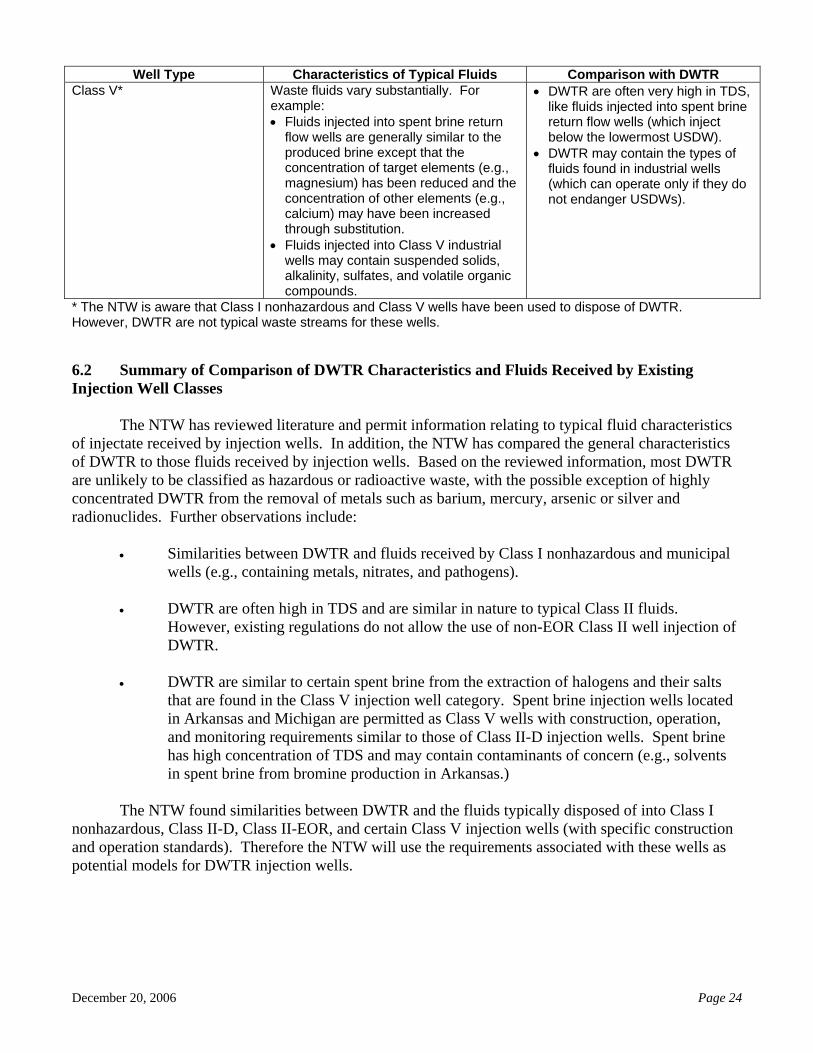
Well Type Characteristics of Typical Fluids Comparison with DWTR Class V* Waste fluids vary substantially. For
example: • Fluids injected into spent brine return
flow wells are generally similar to the produced brine except that the concentration of target elements (e.g., magnesium) has been reduced and the concentration of other elements (e.g., calcium) may have been increased through substitution.
• Fluids injected into Class V industrial wells may contain suspended solids, alkalinity, sulfates, and volatile organic compounds.
• DWTR are often very high in TDS, like fluids injected into spent brine return flow wells (which inject below the lowermost USDW).
• DWTR may contain the types of fluids found in industrial wells (which can operate only if they do not endanger USDWs).
* The NTW is aware that Class I nonhazardous and Class V wells have been used to dispose of DWTR. However, DWTR are not typical waste streams for these wells. 6.2 Summary of Comparison of DWTR Characteristics and Fluids Received by Existing Injection Well Classes The NTW has reviewed literature and permit information relating to typical fluid characteristics of injectate received by injection wells. In addition, the NTW has compared the general characteristics of DWTR to those fluids received by injection wells. Based on the reviewed information, most DWTR are unlikely to be classified as hazardous or radioactive waste, with the possible exception of highly concentrated DWTR from the removal of metals such as barium, mercury, arsenic or silver and radionuclides. Further observations include:
• Similarities between DWTR and fluids received by Class I nonhazardous and municipal wells (e.g., containing metals, nitrates, and pathogens).
• DWTR are often high in TDS and are similar in nature to typical Class II fluids.
However, existing regulations do not allow the use of non-EOR Class II well injection of DWTR.
• DWTR are similar to certain spent brine from the extraction of halogens and their salts
that are found in the Class V injection well category. Spent brine injection wells located in Arkansas and Michigan are permitted as Class V wells with construction, operation, and monitoring requirements similar to those of Class II-D injection wells. Spent brine has high concentration of TDS and may contain contaminants of concern (e.g., solvents in spent brine from bromine production in Arkansas.)
The NTW found similarities between DWTR and the fluids typically disposed of into Class I
nonhazardous, Class II-D, Class II-EOR, and certain Class V injection wells (with specific construction and operation standards). Therefore the NTW will use the requirements associated with these wells as potential models for DWTR injection wells.
December 20, 2006 Page 25
7.0 MINIMUM TECHNICAL RECOMMENDATIONS FOR DWTR INJECTION WELLS
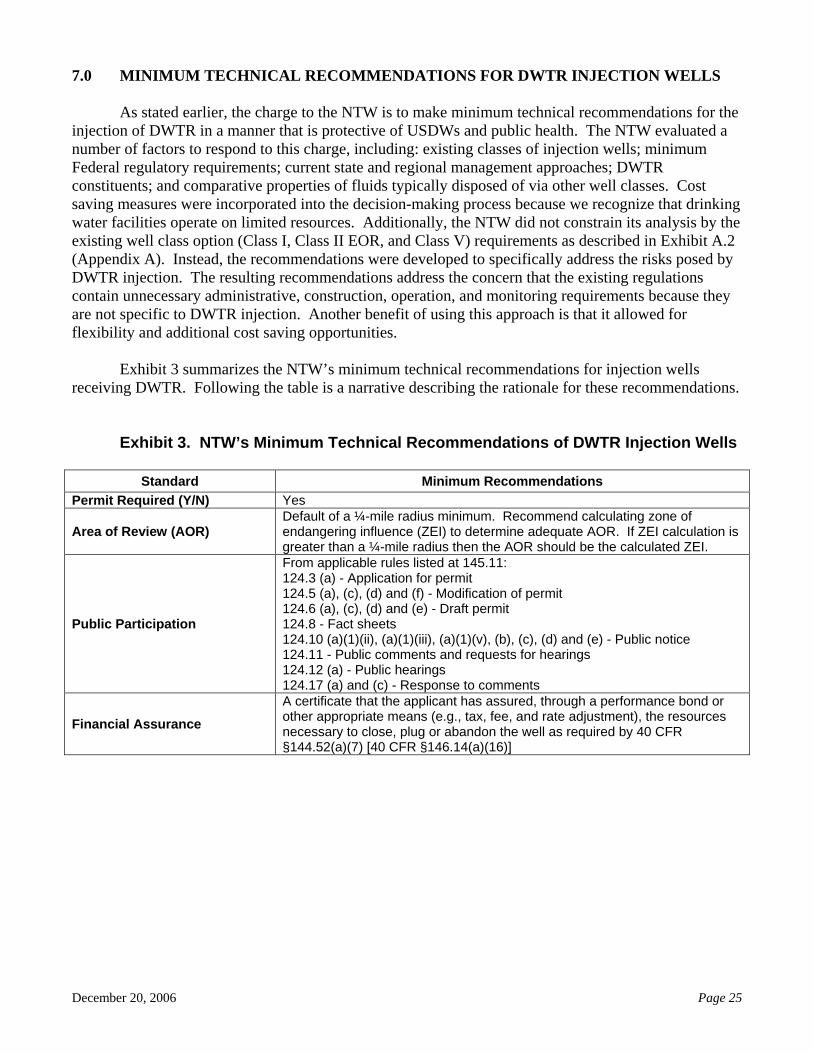
As stated earlier, the charge to the NTW is to make minimum technical recommendations for the injection of DWTR in a manner that is protective of USDWs and public health. The NTW evaluated a number of factors to respond to this charge, including: existing classes of injection wells; minimum Federal regulatory requirements; current state and regional management approaches; DWTR constituents; and comparative properties of fluids typically disposed of via other well classes. Cost saving measures were incorporated into the decision-making process because we recognize that drinking water facilities operate on limited resources. Additionally, the NTW did not constrain its analysis by the existing well class option (Class I, Class II EOR, and Class V) requirements as described in Exhibit A.2 (Appendix A). Instead, the recommendations were developed to specifically address the risks posed by DWTR injection. The resulting recommendations address the concern that the existing regulations contain unnecessary administrative, construction, operation, and monitoring requirements because they are not specific to DWTR injection. Another benefit of using this approach is that it allowed for flexibility and additional cost saving opportunities.
Exhibit 3 summarizes the NTW’s minimum technical recommendations for injection wells receiving DWTR. Following the table is a narrative describing the rationale for these recommendations.
Exhibit 3. NTW’s Minimum Technical Recommendations of DWTR Injection Wells
Standard Minimum Recommendations Permit Required (Y/N) Yes
Area of Review (AOR) Default of a ¼-mile radius minimum. Recommend calculating zone of endangering influence (ZEI) to determine adequate AOR. If ZEI calculation is greater than a ¼-mile radius then the AOR should be the calculated ZEI.
Public Participation
From applicable rules listed at 145.11: 124.3 (a) - Application for permit 124.5 (a), (c), (d) and (f) - Modification of permit 124.6 (a), (c), (d) and (e) - Draft permit 124.8 - Fact sheets 124.10 (a)(1)(ii), (a)(1)(iii), (a)(1)(v), (b), (c), (d) and (e) - Public notice 124.11 - Public comments and requests for hearings 124.12 (a) - Public hearings 124.17 (a) and (c) - Response to comments
Financial Assurance A certificate that the applicant has assured, through a performance bond or other appropriate means (e.g., tax, fee, and rate adjustment), the resources necessary to close, plug or abandon the well as required by 40 CFR §144.52(a)(7) [40 CFR §146.14(a)(16)]
December 20, 2006 Page 26
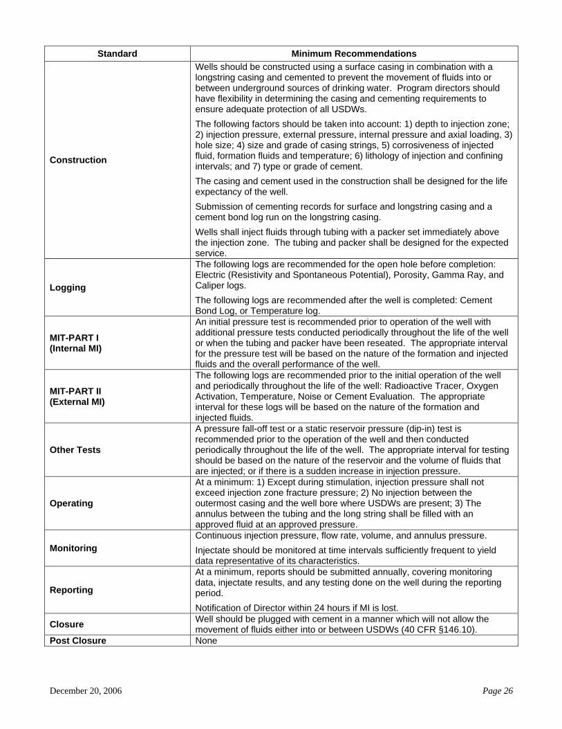
Standard Minimum Recommendations
Construction
Wells should be constructed using a surface casing in combination with a longstring casing and cemented to prevent the movement of fluids into or between underground sources of drinking water. Program directors should have flexibility in determining the casing and cementing requirements to ensure adequate protection of all USDWs.
The following factors should be taken into account: 1) depth to injection zone; 2) injection pressure, external pressure, internal pressure and axial loading, 3) hole size; 4) size and grade of casing strings, 5) corrosiveness of injected fluid, formation fluids and temperature; 6) lithology of injection and confining intervals; and 7) type or grade of cement.
The casing and cement used in the construction shall be designed for the life expectancy of the well.
Submission of cementing records for surface and longstring casing and a cement bond log run on the longstring casing.
Wells shall inject fluids through tubing with a packer set immediately above the injection zone. The tubing and packer shall be designed for the expected service.
Logging
The following logs are recommended for the open hole before completion: Electric (Resistivity and Spontaneous Potential), Porosity, Gamma Ray, and Caliper logs.
The following logs are recommended after the well is completed: Cement Bond Log, or Temperature log.
MIT-PART I (Internal MI)
An initial pressure test is recommended prior to operation of the well with additional pressure tests conducted periodically throughout the life of the well or when the tubing and packer have been reseated. The appropriate interval for the pressure test will be based on the nature of the formation and injected fluids and the overall performance of the well.
MIT-PART II (External MI)
The following logs are recommended prior to the initial operation of the well and periodically throughout the life of the well: Radioactive Tracer, Oxygen Activation, Temperature, Noise or Cement Evaluation. The appropriate interval for these logs will be based on the nature of the formation and injected fluids.
Other Tests
A pressure fall-off test or a static reservoir pressure (dip-in) test is recommended prior to the operation of the well and then conducted periodically throughout the life of the well. The appropriate interval for testing should be based on the nature of the reservoir and the volume of fluids that are injected; or if there is a sudden increase in injection pressure.
Operating
At a minimum: 1) Except during stimulation, injection pressure shall not exceed injection zone fracture pressure; 2) No injection between the outermost casing and the well bore where USDWs are present; 3) The annulus between the tubing and the long string shall be filled with an approved fluid at an approved pressure.
Monitoring Continuous injection pressure, flow rate, volume, and annulus pressure.
Injectate should be monitored at time intervals sufficiently frequent to yield data representative of its characteristics.
Reporting
At a minimum, reports should be submitted annually, covering monitoring data, injectate results, and any testing done on the well during the reporting period.
Notification of Director within 24 hours if MI is lost.
Closure Well should be plugged with cement in a manner which will not allow the movement of fluids either into or between USDWs (40 CFR §146.10).
Post Closure None
December 20, 2006 Page 27
Permitting vs. Rule Authorization
The NTW recommends that DWTR injection wells be permitted instead of rule authorized due to the injectate volumes, potential for corrosion, and the need to prevent fluid movement. Permitting is strongly recommended because it allows for the development of site-specific requirements (e.g., AOR, well construction requirements, and injection limits), public participation, and other protective elements such as financial assurance and monitoring that are not required for rule-authorized wells by the current UIC regulations. This permitting recommendation is consistent with current practices in most states and regions for injection wells accepting either DWTR or analogous fluids. Area of Review (AOR)
An adequate AOR ensures that there are no artificial penetrations that would allow for the movement of fluids from the intended injection zone into USDWs. The NTW recommends a minimum ¼-mile radius AOR for DWTR injection wells. Class II disposal wells accepting comparable volumes and constituents authorized by State UIC programs generally use a ¼-mile AOR. In addition, a ¼-mile AOR is the default requirement for most UIC Programs in the nation (40 CFR §146.6(b)). Furthermore, the NTW recommends that the Zone of Endangering Influence (ZEI; 40 CFR §146.6(a)) be calculated to ensure that a fixed radius of ¼ mile is sufficient to ensure that USDWs are protected from the accidental movement of fluids in situations where existing formation pressures or pressure increase due to long-term disposal activities. Casing and Cementing
Proper casing and cementing prevents the movement of fluids into or between USDWs and provides for well integrity and longevity. The NTW recommends that UIC Program directors be given flexibility in determining the casing and cementing requirements to adequately protect USDWs from DWTR injection, because geology and constituents of concern vary from site to site. The NTW strongly recommends that the following factors be considered for adequate casing and cementing: 1) depth to injection zone; 2) injection pressure, external pressure, internal pressure, and axial loading, 3) hole size; 4) size and grade of casing strings, 5) corrosiveness of injected fluid, formation fluids, and temperature; 6) lithology of injection and confining intervals; and 7) type or grade of cement. In addition, because the bottom of the longstring casing and cement will come in contact with the DWTR fluids, the NTW recommends that compatible construction materials are provided to prevent corrosion and leaks. These recommendations are consistent with other well class requirements for analogous volumes and constituents. Tubing and Packer
Tubing and packers prevent corrosion and extend the life expectancy of the wells by isolating the injected fluid from contact with a majority of the longstring casing. In addition, tubing and packers ensure that the injectate is emplaced in the intended injection zone and provides for real-time monitoring of the annulus to ensure well integrity is maintained. The NTW recommends a tubing and packer given the corrosive nature of the DWTR fluids and as an added layer of protection. The NTW also recommends that the annulus between the tubing and the longstring be filled with an appropriate fluid at an approved pressure to ensure that mechanical integrity of the well is maintained.
December 20, 2006 Page 28
Open Hole Logging
Open-hole logging provides geologic data on the injection zone, confining zone, and the uphole formations. This data is needed to verify the exact location of the formations and the adequacy of the original well design. In addition, open-hole logging provides an opportunity to fine tune the well construction and operating parameters, both of which extend the useful life of the well. The NTW recommends that the following logs be considered for the open hole: Electric, Porosity, Gamma Ray logs (geologic data collection) and caliper logs (cementing program data collection). These recommendations are consistent with other well class requirements for similar constituents and volumes. Cased-Hole Logging
Cased-hole logging verifies that the casing has been adequately set and was not damaged during the installation, ensures that fluids are not moving behind the casing, and identifies cement voids and the cement top. Each element listed is part of a well design that is protective of USDWs and public health. The NTW recommends that either a Cement Bond Log or Temperature Log be run after the well is completed. MIT External
An external mechanical integrity test ensures that the injected fluids remain in the target formation and are not impacting either the portion of the longstring casing below the packer or the bottom hole cement. The NTW recommends the following logs be considered prior to the initial operation of the well and periodically throughout the life of the well: Radioactive Tracer, Oxygen Activation, Temperature, Noise or Cement Evaluation. The appropriate interval for these logs will be based on the nature of the formation and of the injected fluids. A typical interval would be five years; however, the Director should be given discretion in changing the interval depending on the nature and volume of the injectate and the receiving formation.
MIT Internal
An internal mechanical integrity test verifies that the longstring casing and the tubing and packer are intact and are preventing unauthorized movement of the injection fluid. The NTW recommends that a pressure test be performed prior to the initial operation of the well, periodically throughout the life of the well, and when the tubing and packer have been reseated. The UIC Program Director should be given discretion in determining the appropriate testing interval based on the nature of the formation and injected fluids and the overall performance of the well. Reservoir Pressure Determination
The reservoir pressure test monitors the initial reservoir pressure and the subsequent pressure buildup during the operation of the well. This is important to guarantee proper well operation and contributes to the useful life of the well. The NTW recommends consideration of either a pressure fall-off test or a static reservoir pressure (dip-in) test. The UIC Program Director should be given the discretion to determine the appropriate testing interval based on the nature of the reservoir, the volume of injection fluids, or sudden changes in injection pressure.
December 20, 2006 Page 29
Operating
The NTW recommends that, except during stimulation, the injection pressure shall not exceed injection zone fracture pressure to protect the confining zone from fracturing. Fracturing of the injection zone could shorten the useful life of the well by limiting the injection zone from accepting fluids or may allow for the migration of the injectate outside the intended zone and possibly into a USDW. In addition, the NTW strongly recommends that injection between the outermost casing and the well bore be prohibited where USDWs are present. Monitoring
Continuous monitoring of injection pressure, flow rate, volume, and annulus pressure ensures the well is operating within the appropriate permit requirements and provides an early warning of potential problems with the well. The NTW recommends that the UIC Program Director be given discretion to monitor the DWTR injectate at time intervals sufficient to yield data representative of its characteristics. This recommendation is similar to Class II Disposal wells which accept fluids and volumes similar to DWTR. Reporting
Reporting provides information at an appropriate interval to determine compliance and adequacy of existing permit requirements. The NTW recommends that a report covering monitoring data, injectate results and testing results be submitted annually, at a minimum. The NTW also strongly recommends that the operator be required to notify the UIC Program Director within 24-hours if mechanical integrity is lost to allow for appropriate action to ensure the protection of USDWs. Closure and Post Closure Care
Proper closure of a well ensures that fluids will not migrate from the intended target formation after well operations cease. Given the variability in well construction and geology that will exist from well to well, it is difficult to provide specific recommendations that would be appropriate in every situation. Therefore, the NTW recommends that the UIC Program be given discretion to determine the appropriate plugging and abandonment requirements for DWTR wells that are protective of USDWs and meet the general requirements laid out in 40 CFR §146.10.
Post-closure monitoring is typically required for Class I hazardous wells to ensure that hazardous wastes do not leave the intended injection zone. The NTW does not recommend post-closure monitoring because it is not likely that DWTR will be considered hazardous. However, UIC programs may wish to consider utilizing post-closure monitoring on a case-by-case basis depending on the nature of the DWTR fluids and other site-specific conditions. Financial Assurance
Financial assurance is a mechanism to ensure that there are sufficient resources in place to properly close, plug, or abandon the well. Given the depth of these wells, the NTW recommends financial assurance for these wells to ensure that funds are available for proper plugging and abandonment occur. The NTW suggests that Headquarters explore allowing the use of alternative financial assurance mechanisms such as tax or a rate adjustment, since DWTR facilities are typically associated with municipalities and not industry.
December 20, 2006 Page 30
Public Notification
Public notification for DWTR injection well permitting allows for an open decision-making process where the public provides information that may not otherwise be available from the permit data collection process. The notification process also builds public confidence by allowing for an open exchange of information between the public, the operator, and the permitting authority. Cost Considerations
The NTW estimates that the cost of constructing a DWTR injection well based on the recommendations outlined in this report would vary from $500,000 to $1.25 million depending on the specific drilling and construction requirements. The majority of the costs associated with an injection well is attributed to the construction phase, while logging, operating, and reporting are a small portion of the total cost. It is important to note that the typical life expectancy of a properly operated and maintained well is about 40 to 50 years. The anticipated costs of the recommendations laid out in this report are comparable to Class I nonhazardous or Class II disposal well costs. The NTW cautions that due to the flexibility built into the recommendations, it is difficult to estimate exact costs. Lastly, these are minimum recommendations. States may choose more stringent requirements that may impact total costs.
December 20, 2006 Page 31
8.0 SUMMARY AND CONCLUSIONS
Drinking water treatment facilities and drinking water program managers are challenged to find a balance between appropriate treatment technologies, safe waste disposal practices, worker safety, and cost, while ensuring compliance with drinking water regulations for maximum public health protection. These challenges are leading drinking water treatment facilities and drinking water program managers to consider injection wells as one of the preferred disposal options for DWTR. States and regions have asked the National UIC Program for technical guidance in setting appropriate permitting criteria for DWTR injection well construction, operation, and monitoring. To meet this need, the NTW has been charged with evaluating the technical issues associated with DWTR injection wells and developing recommendations for the construction, operation, maintenance and monitoring of these wells.
The NTW considered several factors in the development of technical recommendations for DWTR injection wells, including: existing classes of injection wells; minimum Federal regulatory requirements; current state and regional management approaches; DWTR constituents; costs and comparative properties of fluids typically disposed of via other well classes. Currently there are three injection well categories (Class I, Class II EOR, and Class V) that may be appropriate for DWTR disposal. Each category has potential limitations (cost, need for specific geology, need to meet the endangerment standard) that may make injection an impracticable option when compared to other convention disposal options (e.g., POTW, or surface water disposal). In developing its technical recommendations, the NTW analyzed the minimum Federal regulatory requirements for construction, operation, and monitoring of each of the appropriate categories of injection wells.
The NTW also collected information on current state and regional management practices for DWTR injection wells. The data collection included a survey of all EPA Regions to determine the total number of DWTR injection wells, the category (permitted or authorized by rule), and the specific requirements associated with these wells. A total of 101 DWTR injection wells were found as a result of the data collection effort. Florida has the highest number of DWTR injection wells (75 DWTR injection wells), followed by the Commonwealth of the Northern Mariana Islands (CNMI) (16). Other states with DWTR injection wells included Texas, Kansas, Utah, and Hawaii. Of the 101 injection wells identified, the majority (63) are Class I nonhazardous injection wells. The remaining 38 injection wells identified were Class V injection wells; of those, 31 have been permitted, and 7 have been rule-authorized. The NTW review found that the permit requirements for the Class V injection wells generally appear to be as comprehensive as those for the Class I injection wells. The rule-authorized wells include 5 injection wells in El Paso (these are part of a single desalination pilot facility and only one well has been constructed at this time), one Class V DWTR injection well in Utah (which has not been constructed at this time), and one in Hawaii. The majority of these wells had construction and operating requirements similar in nature to Class I injection wells. The NTW is not aware of any Class II EOR injection wells that are receiving DWTR.
During the information collection efforts, the NTW found very little specific information regarding small shallow systems (e.g., Class V large capacity septic systems or drywells that receive DWTR) beyond the suspicion that such systems exist. The NTW found the lack of data on small shallow systems surprising because this issue continues to be raised by UIC Program Managers. Therefore, the NTW recommends that HQ undertake an effort to specifically target small shallow systems.
Due to the lack of data on smaller volume DWTR wells and the fact that states are looking to implement desalination as a way to meet their future water needs, the NTW decided to focus the
December 20, 2006 Page 32
recommendations analysis on larger volume facilities. The NTW realizes that the recommendations and benefits discussed in this report may be financially unattainable for smaller systems. Therefore, the NTW proposes that HQ consider undertaking a system affordability analysis subsequent to determining the current inventory of small shallow systems to determine potential impacts from the recommendations. The NTW also recommends that HQ consider evaluating capacity building measures that would assist smaller drinking water systems in implementing these recommendations.
The NTW has reviewed literature and permit information relating to various off-the-shelf treatment technologies that generate liquid DWTR. Based on the reviewed information, the various treatments can produce DWTR that contain contaminants at 10 times the concentration of the raw water source. The contaminants can include metals (e.g., arsenic and selenium), radionuclides (e.g., radium 226/228), nitrates, salts and microbes. With elevated concentrations of various contaminants, the NTW believes that, depending on the volume and constituents treated, the injection of concentrates could potentially threaten USDWs and public health. In addition, high TDS and differing geochemistry between the native formation/formation water and the injected concentrates could lead to precipitation of minerals such as calcite, gypsum, and silica that could physically and chemically affect the permeability and porosity of the receiving formation. Certain treatment technologies (e.g., membranes technologies) generate a large proportion of reject water, as compared to the volume of total processed raw water. Based on design documents and permits, the volume of RO reject waters produced can be up to 3 MGD. Because comprehensive national data on DWTR were not available at the time this report was generated, the NTW recommends that HQ undertake a data collection effort to better understand how the constituents found in liquid DWTR are impacted by varying raw water quality and by treatment processes as well as the geochemical interactions between the DWTR and the formation water.
The NTW was unable to find comprehensive data on the raw constituents, loads, and concentrations typically found in drinking water treatment facilities. The NTW was able to collect data from several drinking water treatment facilities, but is unable to determine if these data are representative of all drinking water treatment facilities nationally.
The NTW also reviewed literature and permit information of existing injection wells in various well classes that had similar fluid characteristics to DWTR wells. A comparison was made between the characteristics of DWTR and those existing injection wells of different classes. Based on the reviewed information, similarities were found between DWTR and the fluids typically disposed of into Class I nonhazardous (e.g., containing metals, nitrates, and pathogens), Class II-D (e.g., containing high TDS), and certain Class V injection wells with specific construction and operation standards (e.g., Spent Brine wells receive high TDS fluids).
In developing its recommendations, the NTW did not constrain its analysis to the three well class categories described in Exhibit A.2. Instead, the recommendations were targeted to specifically address the risks posed by DWTR injection. This approach addresses the concern that the existing regulations contain administrative, construction, operation, and monitoring requirements that are not appropriate for DWTR injection wells. Another benefit to using this approach is that it allows for flexibility and additional cost saving opportunities because it is specific to the characteristics and volumes of DWTR.
Based on our analysis of the information gathered for this project, the NTW recommends that DWTR injection wells be permitted instead of rule authorized due to the volumes, potential corrosiveness, and possibility of fluid movement. The permitting recommendations include public participation, financial responsibility, AOR (¼ mile) with a calculated ZEI, appropriate casing and cementing, compatible construction materials, tubing and packer, an appropriate fluid filled annulus,
December 20, 2006 Page 33
annual reporting, and closure. We also suggest a suite of logs and tests that are designed to protect USDWs and prolong the useful life of the well. Lastly, the NTW recommends that the UIC Program Director be given the discretion to determine the appropriate testing, monitoring, and reporting intervals. The NTW estimates that the cost of constructing a DWTR injection well based on the recommendations outlined would vary from $500,000 to $1.25 million depending on the specific drilling and construction requirements. The majority of the cost associated with an injection well is attributed to the drilling and construction phase, while logging, monitoring, and reporting would constitute a small portion of the total cost. While the range in cost seems significant, it is important to note that the typical life expectancy of a properly operated and maintained well is about 40 to 50 years. Finally, the NTW recommends that HQ develop an implementation strategy for these recommendations that includes a policy and legal analysis.
December 20, 2006 Page 34
9.0 REFERENCES American Water Works Association (AWWA). 1999. Water Quality and Treatment. McGraw Hill,
Inc. New York, NY. AWWA Membrane Residuals Committee. “Current Perspectives on Residuals Management for
Desalting Membranes.” 2004. Journal of the American Water Works Association. Volume 96:12 pp. 73-87
ASCE, AWWA, EPA. 1996. Management of Water Treatment Plant Residuals. ASCE (New York,
NY) and AWWA (Denver, Colorado). Bae, B., Y. Jung, W. Han, and H.S. Shin. 2002. Improved Brine Recycling During Nitrate Removal
Using Ion Exchange. Water Research. Volume 36, pp. 3330-3340. Bartley, C.B., P.M. Colucci, and T. Stevens. 1992. The Inorganic Chemical Characterization of Water
Treatment Plant Residuals. Prepared for the Drinking Water Research Division, Risk Reduction and Engineering Laboratory, US EPA.
Efficiencies in Water Treatment Processes. Journal of the American Water Works Association. Volume 70:1 pp. 31-35.
Clifford, D.A., G.L. Ghurye, and A.R. Tripp. 2003. As Removal Using Ion Exchange With Spent Brine
Recycling. Journal of the American Water Works Association. Volume 95:6 pp. 119-130, June 2003.
Clifford, D.A. 1999. “Ion Exchange and Inorganic Adsorption.” Chapter 9 from Water Quality and
Treatment: A Handbook for Community Water Supplies, 5th Edition, by the American Water Works Association (AWWA). New York: McGraw-Hill.
Cornwell, D.A. 1999. “Water Treatment Plant Residuals Management.” Chapter 16 from Water
Quality and Treatment: A Handbook for Community Water Supplies, 5th Edition, by the American Water Works Association (AWWA). New York: McGraw-Hill.
Cornwell, D.A., and R.G. Lee. 1993. Recycle Stream Effects on Water Treatment. Denver, CO:
AWWA Research Foundation. Dotremont, C., B. Molenberghs, W. Doyen, P. Bielen, and K. Huysman. 1999. The Recovery of
Backwash Water From Sand Filters by Ultrafiltration. Desalination. Volume 126, pp. 87-94. DPRA. 1993a. Small Water Systems Byproducts Treatment and Disposal Cost Document. Prepared by
DPRA, Incorporated for EPA OGWDW. April 1993.
December 20, 2006 Page 35
DPRA. 1993b. Water System Byproducts Treatment and Disposal Cost Document. Prepared by DPRA, Incorporated for EPA OGWDW. April 1993.
Fubryka-Martin, J. and Keating, E. (of Los Alamos National Laboratory). “Sustainability of Downhole
Concentrate Disposal: A Geochemical Perspective,” presented at the El Paso Desalination Conference on March 16, 2006
Gallagher, P. 2000. Personal communication. (As cited in MacPhee et al., 2002) Hathaway, S.W. and F. Rubel, Jr. 1987. Removing Arsenic From Drinking Water. Journal of the
American Water Works Association. Volume 79:8 pp.61-65. HDR Engineering, Inc. 2001. Handbook of Public Water Systems-Second Edition. John Wiley & Sons,
Inc. New York, NY. Karanis, P., D. Schoenen, and H.M. Seitz. 1996. Giardia and Cryptosporidium in Backwash Water
From Rapid Sand Filters Used For Drinking Water Production. Zentralbl Bakteriol. Vol 284, no. 1. pp. 107-114. June 1996.
Karimi, A.A., J.C. Vickers, and R.F. Harasickl. 1999. Microfiltration Goes Hollywood: The Los
Angeles Experience. Journal of the American Water Works Association. Volume 90:6 pp.90-103. (As cited in MacPhee et al., 2002)
MacPhee, M.J., G.E. Charles, and D.A. Cornwell. 2001. Treatment of Arsenic Residuals from Drinking
Water Removal Processes. Under contract to the U.S. Environmental Protection Agency, Washington, DC. Publication No. EPA/600/R-01/033. June.
MacPhee, M.J., Y.A. LeGouellec, and D.A. Cornwell. 2002. Treatment of MF Residuals for
Contaminant Removal Prior to Recycle. AWWA Research Foundation. Denver, CO. Mickley, M.C., prepared for the Bureau of Reclamation. 2001. Membrane Concentrate Disposal:
Practices and Regulations. September 2001. Available on the Internet at: http://www.usbr.gov/pmts/water/media/pdfs/report069.pdf.
Min, J.H., L. Boulos, J.C. Brown, D.A. Cornwell, Y.L. Gouellec, E.N. Coppola, J.S. Baxley, and J.A.
Rine. 2005. Innovative Alternatives to Minimize Arsenic, Perchlorate, and Nitrate Residuals. AWWA Research Foundation. Denver, CO.
U.S. Departments of the Army and the Air Force. 1985. Water Supply, Water Treatment. TM 5-813-
3/AFM 88-10, Vol 3, September, 16, 1985. U.S. Department of the Interior. Undated map. Total Dissolved Solids from the Produced Waters
Database in the United States. Available on the Internet at: http://energy.cr.usgs.gov/prov/prodwat/tds.htm.
U.S. Environmental Protection Agency (USEPA). 1977. Manual Treatment Techniques for Meeting the
Interim Primary Drinking Water Regulations. EPA 600/8-77-005.
USEPA. 1992. Evaluation of Demonstration Technologies: Quail Creek Water Supply System. EPA 812-R-93-001.
Wang, L., A. Chen, and K. Fields. 2000. Arsenic removal from drinking water by ion exchange and
activated alumina plants. Prepared for the National Risk Management Research Laboratory, Office of Research and Development, US EPA. October.
December 20, 2006 Page A-1
Appendix A
Exhibit A.1 Existing UIC Disposal Options
Well Type Injection Well Description Disposal Option Considerations Class I, Hazardous Wells used to dispose of wastes
specifically defined as hazardous in Federal law and rules. Can also dispose of nonhazardous waste in addition to the hazardous waste component. Inject fluids beneath the lowermost formation containing a USDW.
• Can accept DWTR that meet the definition of hazardous waste (most DWTR will not meet definition of “hazardous”).
• Can also accept DWTR that is nonhazardous.
• Very stringent protective requirements.
• Very few Class I hazardous facilities can accept offsite waste.
• Can be prohibitively expensive to construct, operate, test and monitor.
• Acceptable geology not always available.
Class I, Nonhazardous Wells used to dispose of wastes that do not meet the definition of “hazardous.” Inject fluids beneath the lowermost formation containing a USDW.
• Can accept DWTR that are nonhazardous.
• Stringent protective requirements.
• Very few Class I nonhazardous facilities can accept offsite waste.
• Can be prohibitively expensive to construct, operate, test and monitor.
• Acceptable geology not always available.
Class II, EOR Wells used to inject fluids to enhance recovery of oil and natural gas.
• DWTR may be used as a “make up fluid” in a Class II EOR well.
Class II-D Wells used to dispose of fluids associated with: natural gas storage operations or conventional oil or natural gas production.
• Not an option: Restricted by regulation.
Class II-H Wells used in the storage of liquid hydrocarbons.
• Not an option: Restricted by regulation.
Class III Wells associated with solution mining (e.g. extraction of uranium, copper, and salts).
• Not an option: Wells are used for solution mining, not disposal.
Class IV Wells used to inject hazardous or radioactive waste into or above USDWs.
• Not an option: Banned by regulation.
Class V Any injection well that is not contained in Classes I to IV.
• Not an option for hazardous waste disposal.
• Demonstration of the “non-endangerment” standard might be difficult for shallow injection.
Exhibit A.2 Summary of Federal Requirements for UIC Wells by Class
Well Class
Requirement Class I Hazardous Class I Nonhazardous Class II EOR Class V
Permit
• Required. [40 CFR §144.31(a)]
• Land Ban Petition.[40 CFR
Part 148, Subpart C]
• Required. [40 CFR §144.31(a)]
• Required, except for existing EOR wells authorized by rule. [40 CFR §144.31(a) and §144.22(a)]
• Not required except for Motor Vehicle Waste Disposal Wells or other wells at the discretion of the Program Director (Most Class V wells are rule authorized). [40 CFR §144.24(a), §144.31(a), and §144.84]
Permit Duration • Up to 10 years. [40 CFR
§144.36] • Up to 10 years. [40 CFR
§144.36] • Up to life of well; reviewed at
least once every 5 years. [40 CFR §144.36(a)]
• Up to 10 years, if permit is required. [40 CFR §144.36]
Area of Review • 2-mile minimum. [40 CFR
§146.63] • ¼-mile minimum. [40 CFR
§146.6(b)(1)] • New wells: ¼-mile fixed radius
or radius of endangerment. [40 CFR §146.6]
• None specified.
Financial Assurance
• . A certificate that the applicant has assured, through a performance bond or other appropriate means, the resources necessary to close, plug, or abandoned the well. [40 CFR §146.70(a)(17)]
• A certificate that the applicant has assured, through a performance bond or other appropriate means, the resources necessary to close, plug, or abandon the well as required by 40 CFR §144.52(a)(7). [40 CFR §146.14(a)(16)].
• A certificate that the applicant has assured, through a performance bond or other appropriate means, the resources necessary to close, plug, or abandoned the well. [40 CFR §146.24(a)(9)]
• None required for Rule-Authorized wells.
• For wells covered by Permit in EPA-implemented programs, the permittee must demonstrate and maintain financial responsibility and resources to close, plug, and abandon the well in a manner prescribed by the director. [40 CFR §144.52(a)(7)]
December 20, 2006 Page A-2
Well Class
Requirement Class I Hazardous Class I Nonhazardous Class II EOR Class V
Public Participation
• (From applicable rules listed at 40 CFR §145.11) 40 CFR §124.3 (a) - Application for permit 40 CFR §124.5 (a), (c), (d) and (f) - Modification of permit 40 CFR §124.6 (a), (c), (d) and (e) - 40 CFR §Draft permit 40 CFR §124.8 - Fact sheets 40 CFR §124.10 (a)(1)(ii), (a)(1)(iii), (a)(1)(v), (b), (c), (d) and (e) - Public notice 40 CFR §124.11 - Public comments and requests for hearings 40 CFR §124.12 (a) - Public hearings 40 CFR §124.17 (a) and (c) - Response to comments.
• (From applicable rules listed at 40 CFR §145.11) 40 CFR §124.3 (a) - Application for permit 40 CFR §124.5 (a), (c), (d) and (f) - Modification of permit 40 CFR §124.6 (a), (c), (d) and (e) - Draft permit 40 CFR §124.8 - Fact sheets 40 CFR §124.10 (a)(1)(ii), (a)(1)(iii), (a)(1)(v), (b), (c), (d) and (e) - Public notice 40 CFR §124.11 - Public comments and requests for hearings 40 CFR §124.12 (a) - Public hearings 40 CFR §124.17 (a) and (c) - Response to comments.
• (From the 1425 Guidance - FR Notice Vol. 46, No. 96, Tuesday, May 19, 1981, page 27339) EPA will consider: Section 5.6 (e) Public Participation - (1) (A) State may give notice or require applicant to give notice of permit application (B) Method of notice should be adequate. This may involve: posting, publication in state register, local newspaper, mailing list, or any other effective method. (C) The Notice should: (i) adequately describe proposed action, (ii) identify where additional information can be obtained, (iii) state how a hearing can be requested and (iv) allow for a minimum 15 day comment period. (2) The Director should provide for hearing upon significant public interest. (A) The Director may notice a hearing on his own and publish notice with notice of an application. (B) Notice of hearing should be published in newspaper of general circulation with 15 days notice. (3) The final state action on the application should contain a response to comments summarizing the comments and their disposition.
• None specified for Rule Authorized wells.
• For wells covered by Permit (from applicable rules listed at 40 CFR §144.31 and §145.11): 40 CFR §124.3 (a) - Application for permit 40 CFR §124.5 (a),(c), (d) and (f) - Modification of permit 40 CFR §124.6 (a), (c), (d) and (e) - Draft permit 40 CFR §124.8 - Fact sheets 40 CFR §124.10 (a)(1)(ii), (a)(1)(iii), (a)(1)(v), (b), (c), (d) and (e) - Public notice 40 CFR §124.11 - Public comments and requests for hearings 40 CFR §124.12 (a) - Public hearings 40 CFR §124.17 (a) and (c) - Response to comments.
December 20, 2006 Page A-3
Well Class
Requirement Class I Hazardous Class I Nonhazardous Class II EOR Class V
Construction Requirements
• Must prevent the movement of fluids into or between USDWs or into any unauthorized zones.
• Materials must meet
compatibility standards. • Casing and cement must
include one surface casing string extending into the confining bed below the lowest formation that contains a USDW, and at least one long string casing must extend to the injection zone. Circulation of cement may be accomplished by staging.
• Injection must take place
through tubing with a packer set at a point specified by the Director, taking several characteristics into consideration. The Director may approve the use of a fluid seal under some circumstances.
[40 CFR §146.65]
• Must be cased and cemented to prevent the movement of fluids into or between USDWs. In establishing specific requirements, Director must consider several factors (e.g., depth, pressure, characteristics of injected fluids, characteristics of casing materials, geological factors)
• Except for municipal wells and
wells injecting non-corrosive fluids, injection must take place through tubing with a packer set immediately above the injection zone, or tubing with an approved fluid seal as an alternative.
[40 CFR §146.12]
• New wells must be cased and cemented to prevent the movement of fluids into or between USDWs. In establishing specific requirements, Director must consider depth to the injection zone, depth to the bottom of all USDWs, injection pressure. May also consider other factors (e.g., nature of formation fluids, lithology of injection and confining zones, external and internal pressures, hole size, characteristics of casing and cement). Requirements do not apply if wells meet applicable State casing and cementing requirements and if injection will not result in the movement of fluids into a USDW or threaten the health of persons
[40 CFR §146.22]
• None specified for Rule Authorized wells with the caveat that the operation of the well must not allow for movement of fluid into a USDW that might cause endangerment to occur. [40 CFR §144.82]
• None specified for wells covered by Permit. [40 CFR §146.51]
December 20, 2006 Page A-4
Well Class
Requirement Class I Hazardous Class I Nonhazardous Class II EOR Class V
Logging and Testing Requirements (Construction)
• Deviation checks. • Resistivity, spontaneous
potential, and caliper logs before surface casing is installed.
• Cement bond and variable
density log, and a temperature log after the casing is set and cemented.
• MIT, consisting of a pressure
test, a radioactive tracer survey, a temperature or noise log, a casing inspection log, if required, and other tests required by the Director.
• Whole cores or sidewall cores
of the confining and injection zones and formation fluid samples from the injection zone.
• Fluid temperature, pH,
conductivity, pressure, and the static fluid level of the injection.
• Estimated fracture pressure;
and other physical and chemical characteristics of the injection zone.
• Pump and injectivity tests
upon completion. [40 CFR §146.66]
• Downhole deviation checks during the drilling process are required and other logs as may be needed are to be considered taking into account available data.
• For surface casing: Resistivity,
spontaneous potential and/or caliper logs may be required before the surface casing is installed.
• A cement bond log,
temperature survey, or density log may be required after the casing is set and cemented. For intermediate/long string casing: Logs before the casing is installed may include: resistivity, spontaneous potential, porosity, gamma ray, and fracture finder logs. Logs required after the casing is set and cemented include: a cement bond log, temperature, or density log.
[40 CFR §146.12]
• For surface casing intended to protect USDWs in areas where the lithology has not been determined, the Director must consider electric and caliper logs before the casing is installed and a cement bond, temperature, or density log after the casing is set and cemented. [40 CFR §146.22(f)(2)(1)(i)]
• For intermediate and long
strings of casing intended to facilitate injection, the Director must consider electric porosity and gamma ray logs before the casing is installed; fracture finder logs; and a cement bond, temperature, or density log after the casing is set and cemented. [40 CFR §146.22(f)(2)(1)(ii)]
• Fluid pressure; estimated
fracture pressure; and physical and chemical characteristics of the injection zone for new Class II wells. [(40 CFR §146.22(g)]
• None specified. [40 CFR §146.51]
December 20, 2006 Page A-5
Well Class
Requirement Class I Hazardous Class I Nonhazardous Class II EOR Class V
MIT-PART I (Internal MI)
• Pressure test annually and after each workover. [40 CFR §146.68(d)(1)]
• Pressure test at least once every 5 years. [40 CFR §146.13(b)(3) and §146.8(b)(2)]
• Pressure test at least once every 5 years. [40 CFR §146.23(b)(3) and §146.8(b)(2)]
• None specified.
MIT-PART II (External MI)
• A temperature, noise, or other approved log (e.g., Oxygen Activation) at least once every 5 years to evaluate the well for fluid movement behind the casing. [40 CFR §146.68(d)(3)]
• A temperature, noise, or other approved log (e.g., radioactive tracer or Oxygen Activation) at least once every 5 years to evaluate the well for fluid movement behind the casing. [40 CFR §146.13(b) and §146.8(c)(1)]
• Adequate cement records may be used in lieu of logs. [40 CFR §146.23(b)(3) and §146.8(c)]
• None specified.
Operating requirements
• Except during stimulation, injection pressure shall not exceed injection zone fracture pressure.
• No injection between the
outermost casing and the well bore where USDWs are present.
• Unless an alternative to a
packer has been approved, the annulus between the tubing and the long string shall be filled with an approved fluid at an approved pressure.
• Maintain MI at all times. [40 CFR §146.67]
• Except during stimulation, injection pressure shall not exceed injection zone fracture pressure.
• No injection between the
outermost casing and the well bore where USDWs are present.
• Unless an alternative to a
packer has been approved, the annulus between the tubing and the long string shall be filled with an approved fluid at an approved pressure.
[40 CFR §146.13]
• Injection pressure shall not exceed injection zone fracture pressure.
• No injection between the
outermost casing and the well bore where USDWs are present.
[40 CFR §146.23]
• None specified for Rule Authorized wells with the caveat that the operation of the well must not allow for movement of fluid into a USDW that might cause endangerment to occur. [40 CFR §144.82]
• None specified for wells covered by Permit. [40 CFR §146.51]
December 20, 2006 Page A-6
Well Class
Requirement Class I Hazardous Class I Nonhazardous Class II EOR Class V
Other Tests
• Annual radioactive tracer survey to evaluate the bottom-hole cement. [40 CFR §146.68(d)(2)]
• Annual pressure fall-off test.
[40 CFR §146.68(e)(1)]
• Casing inspection log after each workover in which the injection string is pulled. Run at Director’s discretion. [40 CFR §146.68(d)(4)
• In addition, the Director may require casing inspection log once every 5 years. [40 CFR §146.68(d)(4)]
and seismicity monitoring as needed. [40 CFR §146.13(d)(2)]
• Injection Pressure, flow rate, and cumulative volume, observed and recorded monthly for enhanced recovery. [40 CFR §146.23(b)(2)]
• Injectate should be monitored
at time intervals sufficiently frequent to yield data representative of its characteristics. [40 CFR §146.23(b)(1)]
• None specified for Rule Authorized wells but in EPA implemented programs, the Director may request information be submitted periodically to determine compliance. [40 CFR §144.27]
• For wells covered by Permit, report on monitoring results as specified in the permit, report any changes to the facility or anticipated noncompliance with permit conditions. Samples and measurements taken for monitoring shall be representative of the monitored activity. [40 CFR §144.51(j)]
December 20, 2006 Page A-7
Well Class
Requirement Class I Hazardous Class I Nonhazardous Class II EOR Class V
Reporting
• Quarterly. [40 CFR §146.69(a)]
• Notification of Director within 24 hours of an alarm or shut-down; or if Mechanical Integrity is lost. [40 CFR §146.67(g)(3) and (h)(3)]
• Quarterly. [40 CFR §146.13(c)]
• Annually. [40 CFR §146.23(c)] • None specified for Rule Authorized wells but in EPA implemented programs, the Director may request information to determine compliance. [40 CFR §144.27]
• For wells covered by Permit, report on monitoring results as specified in the permit, report any changes to the facility or anticipated noncompliance with permit conditions. [40 CFR §144.51(k)]
• For Rule Authorized and Permitted wells the owner/operator must close the well(s) in a manner that prevents movement of fluids into or between USDWs; properly dispose of or manage soil, gravel, sludge, liquids, or other materials. [40 CFR §§144.82(b) and 146.10(c)]
• Permitted wells must also submit a plugging and abandonment report. [40 CFR §144.51(p)]
Post Closure • Conditions set forth under 40 CFR §146.72.
Exhibit A.3 National Overview of DWTR Well Management
Region State Primacy Status
Allow Disposal
of DWTR via
Class I
Allow Disposal of DWTR via
Class II EOR
Allow Disposal of DWTR via Class V
Allow Rule Authorized Disposal of DWTR via Class V
Allow Disposal of DWTR Into or Above a
USDW Under
Certain Conditions
State and Regional Concerns and Comments
Connecticut Primacy/ All classes under 1422 No No Yes No Yes Maine Primacy/ All classes under 1422 No No Yes No Yes
Massachusetts Primacy/ All classes under 1422 No No Yes No Yes New
Hampshire Primacy/ All classes under 1422 No No Yes No Yes
Rhode Island Primacy/ All classes under 1422 No No Yes No Yes
1
Vermont Primacy/ All classes under 1422 No No Yes No Yes
• All states have expressed an interest in DWTR issues.
• New England states ban DWTR injection into Class V injection wells if it exceeds drinking water standards at state designated point of compliance.
• Class V is only option for DWTR disposal. • Region indicates that the states are
struggling with DWTR discharge (small Public Water Systems [PWSs] and private, multi-family residential systems), specifically for radium.
• Region has concerns about small systems concentrating naturally occurring radionuclides and arsenic.
New Jersey Primacy/ All classes under 1422 No No Yes No • Has interest in DWTR issues, specifically with Radium and Methyltertiary-butyl ether (MTBE).
New York DI for all classes Yes Yes No Yes Puerto Rico Primacy/ All classes under 1422 No No Yes No
2
Virgin Islands DI for all classes No No Yes No Yes Delaware Primacy/ All classes under 1422 No No Yes Yes Yes Maryland Primacy/ All classes under 1422 Yes No Yes Yes Yes
Pennsylvania DI for all classes Yes Yes Yes Yes Yes Virginia DI for all classes Yes Yes Yes Yes Yes
Washington, DC
DI for all classes Yes No Yes Yes Yes
3
West Virginia Primacy/ 1422 & 1425 program Yes Yes Yes Yes Yes
• Region has concern that small PWSs may be using system for DWTR disposal.
Alabama Primacy/ 1422 & 1425 program No Yes Yes Florida Primacy for I, III, IV, V (1422) / DI
for II (1425) Yes Yes Yes • Florida wants these Class I industrial
wells not to be required to construct with tubing and packer.
Georgia Primacy/ All classes under 1422 No No Yes Kentucky DI for all classes Yes Yes Yes
4
Mississippi Primacy/ 1422 & 1425 program Yes Yes Yes
December 20, 2006 Page A-9
Region State Primacy Status
Allow Disposal
of DWTR via
Class I
Allow Disposal of DWTR via
Class II EOR
Allow Disposal of DWTR via Class V
Allow Rule Authorized Disposal of DWTR via Class V
Allow Disposal of DWTR Into or Above a
USDW Under
Certain Conditions
State and Regional Concerns and Comments
North Carolina Primacy/ All classes under 1422 No No No No No • North Carolina has a statutory ban on all waste injection through wells; the legislature is looking into changing this.
South Carolina Primacy/ All classes under 1422 No No No No No • South Carolina has found one illegal injector, but cannot authorize under current regulations.
Tennessee DI for all classes Yes Yes Yes Illinois Primacy/ 1422 & 1425 program Yes Yes Yes No No • Class I injection wells are a possible
option since Class V injection wells are not likely to be permitted
• Have had some inquiries about Class V injection wells, but were not an option due to contaminant levels.
Indiana Primacy for II only (1425) Yes Yes Yes Michigan DI for all classes Yes Yes Yes
Minnesota DI for all classes No No Yes Ohio Primacy/ 1422 & 1425 program Yes Yes Yes
5
Wisconsin Primacy/ All classes under 1422 No No Yes No No • State not likely to grant a permit given current anti-degradation laws.
Arkansas Primacy/ 1422 & 1425 program Yes
Louisiana Primacy/ 1422 & 1425 program Yes Yes Yes
• Region 6 supports the use of Class I or Class V injection wells as long as they are constructed properly to meet other appropriate permitting requirements to prevent endangerment and/or migration of fluids.
• Class II-D wells are not a viable option, but Class II enhanced recovery wells may be an acceptable option.
• El Paso, TX has a Class V authorization letter for desalination pilot facility.
7
Iowa DI for all classes Yes No Yes No Yes • Class I or deep Class V injection wells are a potential but Iowa has strict anti-degradation requirements that could be a problem to meet.
December 20, 2006 Page A-10
Region State Primacy Status
Allow Disposal
of DWTR via
Class I
Allow Disposal of DWTR via
Class II EOR
Allow Disposal of DWTR via Class V
Allow Rule Authorized Disposal of DWTR via Class V
Allow Disposal of DWTR Into or Above a
USDW Under
Certain Conditions
State and Regional Concerns and Comments
Kansas Primacy/ 1422 & 1425 program Yes Yes Yes No No • The Kansas Department of Health and Environment (KDHE) has permitted these wells to date as Class I because there are waste streams from other sources that are also directed to the wells that are clearly Class I wastes. But KDHE will be permitting wells receiving only PWS treatment residuals as Class V injection wells. Any DWTR injection wells in Kansas will be required to inject below the lowermost USDW.
Missouri Primacy/ 1422 & 1425 program No Yes Yes Yes Yes • Class V injection wells are the only possible option given the current ban on Class I injection activities in the state.
Nebraska Primacy/ 1422 & 1425 program Yes Yes Yes No Yes • Nebraska has been approached by the city of McCook on requirements for DWTR injection wells; they were told it would have to be permitted as a C1NH well.
• Class I hazardous waste injection banned.
• At this time, there has been very little activity within region 7 but there is a good amount of interest generated within the regulated community about the possible use of injection wells for DWTR disposal and what the requirements are.
Colorado Primacy for II only (1425) Yes Yes • Class V (deep injection) salinity well owned by Bureau of Reclamation.
• Working on second permit for Bureau of Reclamation.
• Not RO process. Montana Primacy for II only (1425) Yes
North Dakota Primacy/ 1422 & 1425 program Yes South Dakota Primacy for II only (1425) Yes
Utah Primacy/ 1422 & 1425 program Yes Yes Yes • Utah rule authorized a Class V RO well (Pony Express Travel Plaza) for a small system to inject DWTR into a 17,000-TDS aquifer (the same source being treated).
8
Wyoming Primacy/ 1422 & 1425 program Yes
December 20, 2006 Page A-11
Region State Primacy Status
Allow Disposal
of DWTR via
Class I
Allow Disposal of DWTR via
Class II EOR
Allow Disposal of DWTR via Class V
Allow Rule Authorized Disposal of DWTR via Class V
Allow Disposal of DWTR Into or Above a
USDW Under
Certain Conditions
State and Regional Concerns and Comments
Arizona DI for all classes No No Yes No Yes California Primacy for II only (1425) Yes Yes Yes No Yes • State does not have primacy for the UIC
program (Class I, III-V); however, California Regional Water Quality Control Boards have issued Water Discharge Requirements for brine disposal, where injectate is used as a saline barrier between fresh and salty aquifers.
• Arsenic has been another contaminant of concern in brine for some California water treatment plants (e.g. Yosemite).
Hawaii DI for all classes No No Yes Yes Yes • Maui County is also looking at a desalination plant to treat pesticide tainted brackish ground water; the concern is whether pesticides will accumulate with the brine and what standards must be met if that is the case.
Nevada Primacy/ 1422 & 1425 program No Yes Yes No Yes • DWTR disposal is a big issue. • Arsenic residuals can be 400-500 ppb in
the discharge; disposal must meet state non-degradation standards.
• State needs answers on these questions. American Samoa
DI for all classes No No Yes Yes Yes
Guam Primacy/ All classes under 1422 No No Yes Yes Yes
9
Mariana Islands
Primacy/ All classes under 1422 No No Yes Yes Yes • The Division of Environmental Quality has issued permits for the injection of RO brine into 16 Class V injection wells at 13 sites (resorts, garment factories, condos, and hospital).
• Specifically interested in monitoring requirements.
December 20, 2006 Page A-12
December 20, 2006 Page A-13
Region State Primacy Status
Allow Disposal
of DWTR via
Class I
Allow Disposal of DWTR via
Class II EOR
Allow Disposal of DWTR via Class V
Allow Rule Authorized Disposal of DWTR via Class V
Allow Disposal of DWTR Into or Above a
USDW Under
Certain Conditions
State and Regional Concerns and Comments
Trust Territories
DI for all classes No No Yes Yes Yes • Currently, DWTR issue is not being addressed in region 9, just recording its occurrence of resources to implement a permitting program of this type of well are not available; having general permit authority would reduce the resource burden.
• Compilation and analysis of existing tools for region 9: what monitoring parameters are cheap and effective? Recommended practices for regulating such systems?
• One challenge for region 9 comes from the lack of authority to regulate cumulative impacts of injection.
• Region 9 suggestions: a single voice for the pros and cons, the general applicability of the UIC regulations; track changes (growth) in inventory over time, catalog primacy permits; if a general permit is issued, track violations; if a general permit cannot be issued, publish voluntary national guidelines and track state adoption or application of those guidelines to specific permits.
Alaska Primacy for II only (1425) Yes Yes Yes • Alaska uses Class I injection wells to dispose of sewage treatment residuals from municipal waste.
Idaho Primacy/ All classes under 1422 No No Yes • Idaho: Small PWSs complaining to state about lack of disposal options for treatment residuals such as nitrate and in cases where there are elevated levels of radionuclides and arsenic.
Oregon Primacy/ 1422 & 1425 program Yes Yes
10
Washington Primacy/ 1422 & 1425 program No Yes Yes • DWTR not likely an issue in Region 10 • General concerns in region 10 that
treatment residuals might become a problem, specifically arsenic and radionuclides.
December 20, 2006 Page A-14
Exhibit A.4 States’ and Territories’ Responsibility for the UIC Program
State Type Well Class(es)
Initial Effective Date Federal Register Notice
Alabama 1425 II August 2, 1982 47FR33268
Alabama 1422 I, III, IV, V August 25, 1983 47FR38640
Alaska 1425 II May 6, 1986 51FR16683
Arkansas 1422 I, III, IV, V July 6, 1982 47FR29236
Arkansas 1425 II March 26, 1984 49FR11179
CNMI 1422 I - V July 17, 1985 50FR28942
California 1425 II March 14, 1983 48FR6336
Colorado 1425 II April 2, 1984 49FR13040
Connecticut 1422 I - V March 26, 1984 49FR11179
Delaware 1422 I - V April 5, 1984 49FR13525
Florida 1422 I, III, IV, V February 7, 1983 48FR5556
Georgia 1422 I - V April 19, 1984 49FR15553
Guam 1422 I - V May 2, 1983 48FR19717
Idaho 1422 I - V June 7, 1985 50FR23956
Illinois 1425 II February 1, 1984 49FR3990
Illinois 1422 I, III, IV, V February 1, 1984 49FR3991
Indiana 1425 II August 19, 1991 56FR41072
Kansas 1422 I, III, IV, V December 2, 1983 48FR54350
Kansas 1425 II February 9, 1984 49FR4735
Louisiana 1422/25 I - V April 23, 1982 47FR17487
Maine 1422 I - V August 25, 1983 48FR38641
Maryland 1422 I - V April 19, 1984 49FR15553
Massachusetts 1422 I - V November 23, 1982 47FR52705
Mississippi 1425 II September 28, 1983 54FR8734
Mississippi 1422 I, III, IV, V August 25, 1983 48FR38641
Missouri 1425 II December 2, 1983 48FR54349
December 20, 2006 Page A-15
State Type Well Class(es)
Initial Effective Date Federal Register Notice
Missouri 1422 I, III, IV, V July 17, 1985 50FR28941
Montana 1425 II November 19, 1996 61FR58933
Nebraska 1425 II February 3, 1984 48FR4777
Nebraska 1422 I, III, IV, V June 12, 1984 49FR24134
Nevada 1422 I - V October 5, 1988 53FR39089
New Hampshire 1422 I - V September 21, 1982 47FR41561
New Jersey 1422 I - V July 15, 1983 48FR32343
New Mexico 1425 II February 5, 1982 47FR5412
New Mexico 1422 I, III, IV, V July 11, 1983 48FR31640
North Carolina 1422 I - V April 19, 1984 49FR15553
North Dakota 1425 II August 23, 1983 48FR38237
North Dakota 1422 I, III, IV, V September 21, 1984 49FR37065
Ohio 1425 II August 23, 1983 48FR38238
Ohio 1422 I, III, IV, V November 29, 1984 49FR46896
Oklahoma 1425 II December 2, 1981 46FR58488
Oklahoma 1422 I, III, IV, V June 24, 1982 47FR27273
Oregon 1422/25 I - V September 25, 1984 49FR37593
Puerto Rico 1422 I – V October 25, 1988 53FR43093
Rhode Island 1422 I - V August 1, 1984 49FR30698
South Carolina 1422 I - V July 10, 1984 49FR28057
South Dakota 1425 II October 24, 1984 49FR42728
Texas 1422 I, III, IV, V January 6, 1982 47FR618
Texas 1425 II April 23, 1982, 47FR17488
Utah 1425 II October 8, 1982 47FR44561
Utah 1422 I, III, IV, V January 19, 1983 48FR2321
Vermont 1422 I - V June 22, 1984 49FR25633
Washington 1422 I - V August 9, 1984 49FR31875
December 20, 2006 Page A-16
State Type Well Class(es)
Initial Effective Date Federal Register Notice
West Virginia 1422/25 I - V December 9, 1983 48FR55127
Wisconsin 1422 I - V September 30, 1983 48FR44783
Wyoming 1425 II November 22, 1982 47FR52434
Wyoming 1422 I, III, IV, V July 15, 1983 48FR32343
Exhibit A.5 Summary of Requirements for Permitted/Authorized DWTR Injection Wells Received by NTW
City Boynton Englewood Highland Beach Punta Gorda Hutchinson Garden City Saipan El Paso State FL FL FL FL KS KS MP TX Associated Water System
City of Boynton Beach West WTP
Englewood Water District
Town of Highland Beach WTP
Burnt Store Utilities WTP
City of Hutchinson RO Plant
Wheatland Electric Cooperative
Hafa Adai Hotel El Paso Water Utilities
Issuing Authority
Florida DEP Florida DEP Florida DEP Florida DEP Kansas DHE Kansas DHE CNMI DEQ TCEQ
Well Class I I V I I I V V Number of Wells
1 1 2 1 1 1 2 5
Description of Permit
Operation of one Class I injection well, IW-1, and an associated deep dual zone monitoring well, MW-1.
Operation of one Class I industrial injection well and monitoring well system for the disposal of nonhazardous brine concentrate produced from the District's RO water treatment plant.
For the disposal and monitoring of nonhazardous RO reject concentrate and non-contact air conditioning return flow.
To inject nonhazardous RO concentrate from the RO Water Treatment Plant.
To inject nonhazardous liquid wastes generated by this facility consisting of effluent from RO water treatment system and water from ground water remediation projects approved by KDHE.
To inject nonhazardous liquid wastes generated by this facility consisting of effluent from RO water treatment and cooling tower blow down water.
Operation of two Class V injection wells to inject nonhazardous RO concentrate from the hotel’s RO Water Treatment Plant.
To inject nonhazardous RO concentrate from a desalination plant used to convert brackish ground water to potable water.
December 20, 2006 Page A-17
City of Boynton
Beach West WTP
Englewood Water District,
FL (DRAFT)
Town of Highland Beach, FL
Burnt Store Utilities, FL
(DRAFT) City of
Hutchinson, KS Wheatland
Electric Cooperative, KS
Hafa Adai Hotel (Saipan, CNMI) El Paso, TX
Spill Prevention & Containment
The emergency disposal method consists of diversion of the membrane softening reject water flow to the City's sanitary sewer force main system, which is discharged to the Wastewater Treatment Plant.
During well shut-in or well failure, flows are authorized to be diverted to the Class I injection wells at the Venice Gardens RO WTP and the Venice Gardens WRF.
In the event of repair or testing of the injection well system, the concentrate must be stored until the system is returned to service.
All applicable Federal, state, and local permits must be in place to allow for any alternate discharges due to emergency or planned outage conditions.
A 43-foot square earthen containment berm, lined with a 60 -mil HDPE liner, will be installed around the three, 12-ft diameter by 15-foot high holding tanks to contain any spillage from the wastewater tanks.
A 12-ft wide by 32-foot high waste holding tank will be installed to insure waste water is directed to the well under gravity flow. The tank will be equipped with a high level alarm to prevent overflow.
Not specified “Spills shall be collected and managed in an appropriate manner according to Commission rules.”
Financial responsibility (y/n)
Y Y Not specified Not specified Y Y Y N
Injection Well Information Well Number IW-1 IW-1 IW-1 IW-1 #1 #1 #1/#2 5 wells Casing Diameter
16 in O.D. 30 in, 20 in, 10.75 in
12.75 in (O.D.) 7.625 in 9 5/8-20 in (varies by borehole size)
7-20 in (varies by borehole size)
Not specified Surface casing, 13-3/8 in; long-string casing, 9-5/8 in
Casing Depth 2713 ft bls 77 ft bls, 450 ft bls, 1040 ft bls
Not specified 2528 ft bls (total depth is 3,268 ft bls)
100-4200 ft 100-5710 ft Not specified Surface casing, 1200 ft; long-string casing, 2900 ft
Casing Material FRP tubing, fully cemented (surface to packer), 16-in diam. .656 -in thick steel casing
steel, sulfate resistant cement grout
Not specified 7 5/8 in steel casing , cemented (type of cement not specified)
Cemented to prevent migration10,H-40, J-55 steel (varies by borehole size)
Cemented to prevent migration (see Hutchinson note),N-80 J-55 Steel (varies by borehole size)
Not specified J-55 Steel
Tubing Diameter
11.78/10.70 in (O.D./I.D)
Not specified Not specified 3 in 7 in 7 in Not specified 7 in
Tubing Depth Not specified Not specified Not specified 2514 ft bls NA 5710-7046 ft Not specified 2875 ft
10 “The well shall be cased and cemented such that: 1) injected fluids and injection zone or other formation fluids do not cause deterioration of the water quality of fresh and/or usable water zones, 2) the loss of fresh and/or usable water due to downward migration is prevented, and 3) the release of injected fluids into an unauthorized zone is prevented.”
December 20, 2006 Page A-18
City of Boynton
Beach West WTP
Englewood Water District,
FL (DRAFT)
Town of Highland Beach, FL
Burnt Store Utilities, FL
(DRAFT) City of
Hutchinson, KS Wheatland
Electric Cooperative, KS
Hafa Adai Hotel (Saipan, CNMI) El Paso, TX
Tubing Material FRP, fully cemented
Not specified Not specified FRP K-55 Tubing 7 in perforated liner with 20 holes/ft
Not specified J-55
Injection Depth/Interval
2780-3312 ft bls 1800 ft bls 240-300 ft bls 3268 ft bls 4038-4740 ft bls 5720-7720 ft bls 300-460/280-460 ft bls
2300 to 4300 ft bls (injection zone)
Injection Location (i.e. name of aquifer/formation)
Boulder Zone, Oldsmar Formation
Ocala Limestone and Avon Park Formations, Upper Florida aquifer
Peace River Formation
Oldsmar Formation
Arbuckle Arbuckle Not specified Fusselman and Montoya
Well Construction Criteria
Not specified Not specified Not specified Not specified The well shall be cased and cemented such that: 1) injected fluids and injection zone or other formation fluids do not cause deterioration of the water quality of fresh and/or usable water zones, 2) the loss of fresh and/or usable water due to downward migration is prevented, and 3) the release of injection fluids into an unauthorized zone is prevented.
The well shall be cased and cemented such that: 1) injected fluids and injection zone or other formation fluids do not cause deterioration of the water quality of fresh and/or usable water zones, 2) the loss of fresh and/or usable water due to downward migration is prevented, and 3) the release of injection fluids into an unauthorized zone is prevented.
Not specified Must meet 30 TAC Chapter 331 standards for Class I and Class V wells [331.62 requires setting and cementing of two strings of casing; surface casing must be set and cemented through the base of USDWs.]
December 20, 2006 Page A-19
City of Boynton
Beach West WTP
Englewood Water District,
FL (DRAFT)
Town of Highland Beach, FL
Burnt Store Utilities, FL
(DRAFT) City of
Hutchinson, KS Wheatland
Electric Cooperative, KS
Hafa Adai Hotel (Saipan, CNMI) El Paso, TX
Injectivity Testing
Injection rate, initial and final totalizer readings, time from initial to final totalizer readings, static injection wellhead pressure, wellhead injection pressure fall-off, final pressure upon test cessation, wellhead pressure with no flow, monitoring zone pressures.
Injectivity index (gallons per minute/ specific pressure).
Specific Injectivity (gallons/psi), initial and final totalizer readings, static injection wellhead pressure (psig), wellhead injection pressure fall-off (psig every 30 seconds until again static), final pressure upon test cessation (approx 10-15 min).
Specific injectivity index (gallons per minute/specific pressure).
Injection flowrate and volume, wellhead annulus pressure, wellhead injection pressure, and seal pot liquid level.
Injection flowrate and volume, wellhead annulus pressure, wellhead injection pressure, and seal pot liquid level.
Injection well flowrate, well head pressure, conductivity of the facility raw water supply.
Pressure test data for casings and the injection zone, surface injection pressure, maximum instantaneous rate of injection, injection volume, pressure falloff test.
Operational Testing
Flow rate, flow volume, injection pressure.
Flow rate, total injection volume, injection pressure, water level.
Continuous indicating, recording, and totalizing devices for effluent flow rate and volume, injection pressure, and monitoring zone pressure.
Continuous recording for injection pressure, annular pressure, flow rate, total volume WTP concentrate injected, fluid added to/removed from annulus, pressure added to/removed from annulus.
Pressure buildup in the injection zone, static fluid level of the injection interval.
Pressure buildup in the injection zone, static fluid level of the injection interval.
Preventative maintenance procedures for fouling.
Continuous monitoring and digital recording of injection pressure, injection rate, and injection volume, and annulus pressure.
Mechanical Integrity Testing
TV survey, pressure test, radioactive tracer survey (RTS), and temperature log; every 5 years.
Testing procedure, TV Survey; every five years.
Pressure test, temperature logging, TV survey & interpretations.
Demonstrate mechanical integrity at least once every 5 years, TV Survey.
Internal and external MIT every 5 years, upon work-over, or as directed.
Internal and external MIT every 5 years, upon work-over, or as directed.
Every 3 years; gravity pressure test (or other DEQ approved test).
Annually; testing shall include a pressure falloff test.
December 20, 2006 Page A-20
City of Boynton
Beach West WTP
Englewood Water District,
FL (DRAFT)
Town of Highland Beach, FL
Burnt Store Utilities, FL
(DRAFT) City of
Hutchinson, KS Wheatland
Electric Cooperative, KS
Hafa Adai Hotel (Saipan, CNMI) El Paso, TX
Injectate Information Type of Injectate
Nonhazardous membrane softening reject water.
Nonhazardous brine concentrate.
Nonhazardous RO reject concentrate.
Nonhazardous RO concentrate.
Nonhazardous RO effluent and water from ground water remediation projects.
Nonhazardous RO effluent and cooling tower blow down.
RO brine water. Discharge water from a desalination plant used to convert brackish ground water to potable water.
Maximum Injection Rate
10 ft/s Not specified Not specified 219 gpm (10 ft/s or 392 gpm following expansion)
Monitor Monitor 300 gpm 1,100 gpm for any individual well (average rate of injection shall not exceed 2,100 gpm for all wells combined).
Maximum Daily Injection Volume/Peak Hourly Flow Rate
2.40 MGD (7.5 ft/s) (4.04 MGD following expansion)
1.08 MGD (750 gpm)
0.750 MGD (0.860 MGD following expansion)
.315 MGD (0.564 MGD following expansion)
2.3 MGD 1.872 MGD 0.4 MGD About 3 MGD on average for all wells combined.
Pressure Maximum casing/tubing: 100 psi
Maximum casing: 50 psi
At the wellhead: 10 ft/s
Maximum casing: 103 psi
Injection: Gravity flow, no pump pressure allowed.
Injection: Gravity flow, no pump pressure allowed.
Not specified Authorization letter says: “injection pressure shall not exceed 0.0 psig”
Minimum Allowable Operating Annulus Pressure
Not specified Not specified Not specified Not specified 60 psi 60 psi Not specified Not specified
Exhibit A.6 Summary of DWTR Characteristics by Treatment
Treatment Goal
Process Characteristics of DWTR
Desalination Reverse Osmosis (RO) and Nanofiltration (NF)
TDS concentrations depend on the membrane characteristics and the concentration in the source water. For seawater the concentration factors typically range from 1.7 to 2.5 and result in concentrations of 60,000 to 80,000 mg/L. Discharges from RO and NF units for brackish ground water range in concentration from 2,000 to 40,000 mg/L.11
Reverse Osmosis and Nanofiltration
Arsenic concentrations in the DWTR will depend primarily on the source water quality and the system efficiency. DWTR can contain arsenic at 10 times the concentration of the raw water.12 High recoveries will also produce high TDS concentrations. The volume produced will depend on the plant flow rate, the system recovery, and other factors.
Arsenic Removal
Activated Alumina
Contaminant concentrations in the brine stream are dependent on the source water quality, the regenerant concentration, and how well ions adsorbed to the media are exchanged or desorbed during regeneration. Arsenic (in the form of arsenate) is highly preferred by activated alumina (AA). However, competing ions such as fluoride could result in lower concentrations of arsenic in the residual waste stream. The regeneration process for AA is typically not as efficient as Ion Exchange resulting in potentially lower arsenic concentrations in the residual waste stream. For example, in the AA regeneration process, about 75 percent of the arsenic is typically recovered in the brine and the other 25 percent remains adsorbed to the media.13 Regarding the volume of residuals produced, backwash water, regenerant streams, and the early part of acid neutralization constitute about 4 percent of the plant throughput.14
Arsenic Removal (cont.)
Ion Exchange Like AA, contaminant concentrations in the brine stream are dependent on the source water quality, the regenerant concentration, and how well ions adsorbed to the resin are exchanged or desorbed during regeneration. If co-occurring contaminants such as uranium and sulfate are present in the source water, arsenic concentrations in the residual waste stream will be lower. TDS concentrations can be between 35,000 and 45,000 mg/L or even higher (one study indicated levels of 120,000 mg/L). Mixing the brine stream with the fast rinse and/or backwash streams (which is most commonly done in water treatment plants) can reduce the TDS and contaminant concentrations in the wastewater by an order of magnitude15 resulting in lower arsenic concentrations (and a larger volume of water to dispose). For example, prior to dilution with the backwash and rinse waters, one case study listed a concentration of arsenic in the brine stream of 15 mg/L arsenic. In comparison to other technologies, one study stated after blending all waste waters produced, the arsenic concentration was 25 mg/L which was significantly higher as compared to AA, RO, and NF processes.16 Wastewater produced from the regeneration process is 1.5 to 10 percent of the overall volume treated.17 Co-occurring contaminants will affect volumes generated.
11 AWWA 2004. 12 Based on a recovery rate of approximately 90% and a rejection rate of close to 100%. 13 AWWA 1999. 14 HDR Engineering 2001. 15 DPRA 1993. 16 MacPhee et al. 2001. 17 ASCE et al. 2001.
December 20, 2006 Page A-24
Treatment Goal
Process Characteristics of DWTR
Granular Bed Filtration
Arsenic concentrations in the spent filter backwash water will depend on the amount of arsenic in the source water, the amount of arsenic precipitated in the oxidation/coagulation process, and the backwash frequency. The precipitated arsenic that collects on the filter bed will be in the backwash water. In one case study, levels up to 15 times the MCL were observed. Specialty filter medias such as manganese greensand can also remove arsenic. Other contaminants in the source water such as microbes can also be concentrated. Spent filter backwash water generated is approximately 3 to 10 percent of total plant production.
Reverse Osmosis and Nanofiltration
Radionuclide concentrations in the residual waste stream will depend on the source water quality, the percent rejection of individual radionuclides (uranium and radium), the system recovery, and other factors. Like arsenic, radionuclides in the feed stream can be concentrated by a factor of as much as 10 in the residual waste stream.18 One system with a mean radium concentration in the raw water of 14.3 pCi/L, observed average concentrations of 46.1 pCi/L and concentrations as high as 69 pCi/L in the residual waste stream. High recoveries will also produce high TDS concentrations. The volume produced will depend on the plant flow rate, the system recovery, and other factors. One system observed levels 69 pCi/L of Radium, over 10 times the MCL.
Granular Activated Carbon (GAC) Adsorption
The residual waste stream generated from GAC adsorption will contain suspended solids and possibly microbial matter.19 Backwashing does not remove contaminants, adsorbed to the media.
Radionuclides
Ion Exchange Contaminant concentrations in the residual waste stream are dependent on the source water quality, the regenerant concentration, and how well ions adsorbed to the resin are exchanged or desorbed during regeneration. Radium and uranium are the most preferred contaminants for ion exchange.20 Radium is preferred 2 to 1 over the next most preferred contaminant (barium) for cation exchange and uranium is preferred over 21 times more than the next contaminant (sulfate) and over 700 times more than arsenic for anion exchange. Therefore, if radionuclides are present, the concentrations could be extremely high. TDS concentrations can be between 35,000 and 45,000 mg/L or even higher (one study indicated levels of 120,000 mg/L). Mixing the brine stream with the fast rinse and/or backwash streams (which is most commonly done in water treatment plants) can reduce the TDS and contaminant concentrations in the wastewater by an order of magnitude21 resulting in lower radionuclide concentrations (and a larger volume of water to dispose). Wastewater produced from the regeneration process is 1.5 to 10 percent of the overall volume treated.22
18 Based on a recovery rate of approximately 90% and a rejection rate of close to 100%. 19 AWWA 1999. 20 When using strong acid cation (SAC) and strong base anion (SBA) resins, respectively. 21 DPRA 1993. 22 ASCE et al. 1996.
December 20, 2006 Page A-25
Treatment Goal
Process Characteristics of DWTR
Granular Bed Filtration
Radionuclides concentrations in the spent filter backwash will depend on the concentration in the source water, the type of filtration process used, and other factors specific to the type of filtration process (pH, coagulants, media type, etc.). For example, uranium can be removed by coagulation/filtration with removal efficiencies between 85 and 95 percent.23 Green sand and pre-formed Hydrous Manganese Oxide filtration can remove radium with removal efficiencies between 19 and 82% and up to 90%, respectively. Lime softening will remove both radium and uranium (75 to 90% for radium and 16 to 97% for uranium24). One system had concentrations between 45 and 69 pCi/L of radium in its backwash water, well above the MCL of 5 pCi/L. Spent filter backwash water generated is approximately 3 to 10 percent of total plant production.
Granular Bed Filtration
Spent filter backwash waters can contain concentrations of microbial contaminants such as Giardia and Cryptosporidium above influent levels. Studies have found concentrations ranging from 0.8 to 250 cysts/L. These concentrations represented increases over the source by a factor 1.3 to 50. Metals such as iron and manganese present in the source water can also be elevated.
Microbes
Microfiltration/ Ultrafiltration (MF/UF)
MF/UF can remove larger sized particles such as bacteria and viruses (viruses primarily removed by UF) at high recoveries (95%) depending on source water quality, the type and number of membranes, and other factors. The pore size for MF/UF membranes is too large to reject TDS. Therefore, depending on the type of water used for backwashing, TDS concentrations will likely not exceed those in the source water.
Nitrate Reverse Osmosis and Nanofiltration
Like arsenic, nitrate concentrations in the residual waste stream will depend on the source water quality, percent rejection of nitrate, the system recovery, and other factors. Nitrate in the feed stream can be concentrated by a factor of as much as 10 in the residual waste stream. 25 High recoveries will also produce high TDS concentrations. The volume produced will depend on the plant flow rate, the system recovery, and other factors.
23 USEPA 1992. 24 Brink et al. 1978; USEPA 1977; USEPA 1992. 25 Based on a recovery rate of approximately 90% and a rejection rate of close to 100%.
December 20, 2006 Page A-26
Treatment Goal
Process Characteristics of DWTR
Ion Exchange Contaminant concentrations in the residual waste stream are dependent on the source water quality, the regenerant concentration, and how well ions adsorbed to the resin are exchanged or desorbed during regeneration. If the resin is not nitrate-selective and co-occurring contaminants such as uranium, sulfate and/or arsenic are present in the source water, nitrate concentrations in the residual waste stream will be lower (however, uranium and arsenic would be higher). In addition, nitrate concentrations could be lower if denitrification were used to treat the residual waste stream. In one study, a denitrification reactor removed 96 percent of nitrate from the residual waste stream.26 TDS concentrations can be between 35,000 and 45,000 mg/L or even higher (one study indicated levels of 120,000 mg/L). Mixing the brine stream with the fast rinse and/or backwash streams (which is most commonly done in water treatment plants) can reduce the TDS and contaminant concentrations in the wastewater by an order of magnitude27 resulting in lower nitrate concentrations (and a larger volume of water to dispose). Wastewater produced from the regeneration process is 1.5 to 10 percent of the overall volume treated.28
26 Bae et al. 2002. 27 DPRA 1993. 28 ASCE et al. 1996.
December 20, 2006 Page B-1
Appendix B DWTR Characteristics
B.1 Liquid Residuals Produced during Desalination B.1.1 Nanofiltration and Reverse Osmosis
Desalination is most commonly accomplished using membranes. The membrane system uses pressure to force the water through the pores in the membrane. Contaminants larger than the membrane pore do not pass through the membrane and are rejected in a concentrate29 stream, which must be disposed. Reverse osmosis (RO) membranes have the smallest pore openings and are used for desalinating seawater and removing other small contaminants. Nanofiltration (NF) membranes have larger pores and can be used for less brackish waters and larger molecules. In addition to the concentrate stream, the membranes must be cleaned periodically. The spent cleaning solutions are small volumes and generated only periodically. They are often blended back into other waste streams for disposal.30
The constituents in the concentrate stream will reflect the source water quality and pretreatment chemicals used, and will be concentrated to varying degrees depending on the type and magnitude of the driving force, the type and number of membranes used, the percent rejection of individual contaminant species, and the overall system recovery.31 RO units typically have system recoveries ranging from 60 to 85 percent and ion rejection rates for TDS of 85 to 96 percent.32 NF units typically have system recoveries ranging from 75 to 90 percent of ion rejection rates for hardness of 80 to 90 percent.
The pH of the concentrate could be acidic, basic, or neutral depending on pretreatment and post-treatment pH adjustments. Generally, when the source water quality and system recovery rates are relatively constant, the concentrate stream will yield a consistent chemical composition over time. Characteristics
Concentrates from membrane separation processes can have very high levels of TDS, possibly exceeding 45,000 mg/L and elevated concentrations of other constituents in the feed stream.33
Mickley (2001) studied nine membrane drinking water plants in Florida. The identities of the plants were withheld, so it is not certain which membrane processes were used at each plant, but it is likely that many of them used RO. He found TDS concentrations ranging from 4,303 to 26,029 mg/L, fluorine concentrations ranging from 1.4 to 8.6 mg/L, and strontium concentrations ranging from 14 to 160 mg/L.
The American Water Works Association’s Residual Management Committee reported in 2004
that for seawater, TDS is typically concentrated by a factor of 1.7 to 2.5 over the TDS concentration in the seawater and results in residual concentrations of 60,000 to 80,000 mg/L. For brackish ground water TDS concentrations in the reject water are concentrated by factors ranging from 2.9 to 6.7 and produce
29 The concentrate stream could also be classified as the “reject” stream. In addition, it may also be classified as “brine” if the TDS concentration exceeds 36,000 mg/L or the membrane process is used for desalination. 30 Mickley 2001 31 ASCE et al. 1996 32 Mickley 2001 33 ASCE et al. 1996
December 20, 2006 Page B-2
residual concentrations in the range of 2,000 to 40,000 mg/L. For surface water and fresh ground water TDS is concentrated in the reject stream by a factor ranging from 5 to 10 and can produce residual concentration from 1,330 to 3,330 mg/L.34
Monitoring data for a reverse osmosis plant injecting into a disposal well in the State of Florida were examined. The plant treated brackish ground water and injected it into an underground aquifer. For the first 6 months of 2006, the injectate from the plant contained an average of 26,850 mg/L TDS, and 1,949 mg/L sulfate. The source water contained 7,500 mg/L of TDS and 450 mg/L of sulfate. Volumes
The volume of concentrates produced by a membrane system is dependent on the system
recovery and plant flow rate. A membrane unit with 90 percent system recovery will produce a concentrate stream which is 10 percent of the plant influent. B.2 Liquid Residuals Produced during Treatment for Arsenic B.2.1 Nanofiltration and Reverse Osmosis
The membrane processes for treatment of arsenic works in the same manner as described above for desalination. Characteristics
Arsenic is primarily found in ground water (although it can be present in surface waters) where TDS concentrations are much lower than in seawater. Therefore, TDS concentrations in the concentrate stream will typically be lower than from desalination. The concentration of arsenic found in the concentrate stream will depend on the ion rejection rate (high due to the relatively large molecular weight of the arsenic species) and the overall system recovery.
Volume
The volume of concentrate produced will depend on the system recovery and plant flow rate. Lower TDS source waters may produce higher recoveries.
B.2.2 Ion Exchange
In ion exchange certain contaminants are removed from the source water by exchanging with ions such as sodium or chloride attached to the resin. Over time, the resin sites become loaded with contaminants and regeneration is required. Regeneration typically produces three types of waste streams: backwash, regenerant brine, and rinse streams. Contaminant concentrations in the residual waste stream are dependent on the source water quality, regenerant concentration, and how well ions adsorbed to the resin or media are exchanged or desorbed during regeneration.
The brine stream contains contaminants and other ionic species loaded onto the resin and any
excess regenerant. The result is a stream with very high levels of TDS, potentially exceeding 35,000 mg/L (ASCE et al. 1996). The rinse stream contains some diluted regenerant and trace contaminants.
34 AWWA 2004.
December 20, 2006 Page B-3
The backwash stream will contain trace contaminants and some suspended solids. Usually a plant will combine the brine stream with the backwash and rinse streams to lower the concentrations and produce a less corrosive residual35.
Characteristics
Arsenic can be removed by ion exchange but its concentration reduction may be reduced by competition with co-occurring contaminants depending on the concentration of the source water. If co-occurring contaminants such as uranium and sulfate are present in the source water, arsenic concentrations in the residual waste stream will be lower.36 TDS concentrations can be between 35,000 and 45,000 mg/L or even higher. Mixing the brine stream with the fast rinse and/or backwash streams (which is most commonly done in water treatment plants) can reduce the TDS and contaminant concentrations in the wastewater by an order of magnitude37 resulting in lower arsenic concentrations (and a larger volume of water to dispose).
Wang et al. (2000) tested spent brine from an ion exchange water treatment plant. The average
concentrations of arsenic, aluminum, iron, and manganese in the brine produced at this plant were 15,623 μg/L (ranging from 1,830 to 38,522 μg/L), 20.5 μg/L, 207 μg/L, and 3.0 μg/L, respectively. Arsenic concentrations were significantly higher in the slow rinse stream (averaging 1,332 μg/L) compared to the backwash and fast rinse streams (averaging 59.4 and 108 μg/L, respectively) for five ion exchange regenerations. In addition, aluminum, iron, and manganese concentrations in the backwash water averaged 432 μg/L, 1,102 μg/L, and 40.2 μg/L, respectively, with an average TSS concentration of 14,000 μg/L and an average pH of 7.438. Stream volumes were not available and therefore, final arsenic concentrations of the combined streams could not be calculated. However, under the typical bed volumes produced for backwash and rinse streams during ion exchange regenerations, flow equalization could reduce arsenic concentrations significantly.
MacPhee et al. (2001) analyzed liquid residuals from a variety of drinking water treatment
processes, including ion exchange. After blending individual ion exchange waste streams, concentrations of total arsenic in the untreated liquid residuals approached 25 mg/L.
In a study by the US Army and Air Force (1985), DWTR brines from ion exchange regeneration
were found to contain calcium, magnesium, and sodium, although they may also contain small amounts of iron, manganese, and aluminum. TDS concentrations in these brines are most often between 35,000 and 45,000 mg/L (3.5-4.5%) and can range as high as 95,000 to 120,000 mg/L (9.5-12%)39.
MacPhee et al. (2001) analyzed liquid residuals from a variety of drinking water treatment
processes, including ion exchange. Untreated ion exchange residual streams also exhibited a high pH (9.5 in one case) and high levels of TDS (up to 6,240 mg/L) and sulfate (up to 910 mg/L).
Clifford (2003) found that arsenic in the brine stream was concentrated by a factor of 161 over the concentration in the source water.
35 DPRA 1993b 36 Clifford 1999 37 DPRA 1993a 38 Wang et al. 2000 39 US Army and Air Force, 1985
December 20, 2006 Page B-4
Volume
According to Clifford (1999), regeneration of ion exchange resins typically requires between 1 and 5 bed volumes of regenerant and between 2 and 20 bed volumes of rinse water. Total wastewater is usually less than 2% of finished water. If backwash and/or fast rinse waters are combined with the brine stream, the volume requiring disposal could range from 1.5 to 10 percent of the overall volume treated (ASCE et al. 1996). The volume can be reduced by recycling the brine. This can decrease the volume by a factor of up to 20, but will increase the concentration by the same factor (Clifford 2003). B.2.3 Granular Bed Filtration
Granular bed filters remove suspended solids, microbes and other contaminants through physical screening, attachment to granules and other mechanisms. Granular bed filters are backwashed periodically to maintain operation. The backwash water will contain suspended solids, microbes, metals, and coagulants added to aid in filtration. Filter backwash water typically contains 10 to 20 percent of the total solids generated and has between 30 to 300 mg/L suspended solids. These values depend on the filter influent turbidity and the amount of backwash water in relation to production water (Cornwell 1999). Characteristics
Arsenic concentrations in the spent filter backwash water will depend on the amount of arsenic in the source water, the amount of arsenic precipitated in the oxidation/coagulation process and the backwash frequency. The precipitated arsenic that collects on the filter bed will be in the backwash water. Specialty filter medias such as manganese greensand can also remove arsenic. Other contaminants in the source water such as microbes can also be concentrated.
Dotremont et al. (1999) described the quality of sand filter backwash water (type of filter not
specified) at four drinking water treatment facilities of a European water company (i.e., PIDPA). The backwash water contained varying levels of iron, calcium, manganese, and arsenic. Arsenic ranged from less than 1 to 154 μg/L. Iron ranged from 0.2 to 447.7 mg/L. Calcium ranged from 35 to 69 mg/L. Manganese ranged from 22 to 355 μg/L. Volume
Spent filter backwash water generated is approximately 3 to 10 percent of total plant production. Filter backwashing episodes can last for 15-20 minutes at a rate of 15 to 30 gpm/ft2. The rate depends on media size and water temperature (Cornwell 1999). An older study on drinking water supply and treatment by the US Army and Air Force (1985) estimated backwash water volumes of 1 to 3 percent of the total processed raw water.
B.2.4 Activated Alumina
For activated alumina (AA), contaminants preferred by activated alumina are removed from the
source water by adsorbing to the media. Over time, the media becomes loaded with contaminants and regeneration is required. During regeneration, activated alumina systems produce: backwash water, the regenerant waste stream, rinse water, and an acid neutralization stream.40
40 HDR Engineering 2001
December 20, 2006 Page B-5
AA brines contain contaminants and other ionic species previously loaded on the media, along with excess regenerant (e.g., hydrochloric acid or sodium hydroxide). The result is a waste stream with very high levels of TDS. The chemical concentration of the brine depends on the source water quality, the regenerant concentration, and the efficiency of the regeneration process. AA rinse streams contain diluted concentrations of contaminant and the reagents used during regeneration. The rinse stream will likely be mixed with the brine stream to lower concentrations.
The acid neutralization waste stream is mainly comprised of salts and few contaminants. The
acid neutralization step may occur immediately following regeneration; therefore, acid may be added to the AA influent water thus combining acidification and adsorption of the media into one step (AWWA 1999). In this scenario adsorption cannot take place until the AA media is neutralized with acid. Therefore, during initial processing of AA influent water, contaminants will not be removed and the AA effluent will need to be temporarily discharged as waste.41 The residual liquid being discharged to waste will contain contaminants present in the AA influent water, salts from the neutralization process, and hydroxides adsorbed to the media.
Characteristics
Arsenic (in the form of arsenate) is highly preferred by activated alumina. The presence of competing ions such as fluoride, however, could result in lower concentrations of arsenic in the residual waste stream. The regeneration process for AA is typically not as efficient as ion exchange, resulting in potentially lower arsenic concentrations in the residual waste stream. For example, when an AA system containing arsenic is regenerated, about 75 percent of the arsenic is typically recovered in the brine with the other 25 percent remaining adsorbed to the media.42 The concentration of arsenic will depend on the volume of regenerant used and the volume of any backwash, rinse, or acid neutralization water that it is mixed with. In addition, higher raw water arsenic concentration would necessitate more frequent regeneration. Volume
The volume of backwash, brine, rinse water, and acid neutralization streams generated over time is based on the treatment facility’s raw water quality, the size of the AA unit, the regenerant concentration, the adsorption capacity of the media, and the regeneration frequency. Backwash water, regenerant streams, and the early part of the acid neutralization stream (i.e., before the activated alumina is neutralized) constitute about 4 percent of the plant throughput.43
B.3 Liquid Residuals Produced during Treatment for Radionuclides B.3.1 Nanofiltration and Reverse Osmosis
The membrane processes for treatment of radionuclides works in the same manner as described above for desalination.
Radionuclides are primarily found in ground water (although they can be present in surface waters) where TDS concentrations are much lower than in seawater. Therefore, TDS concentrations in the concentrate stream will typically be lower as compared to concentrations from desalination. The concentration of radionuclides (radium and uranium) found in the concentrate stream will depend on the ion rejection rate and the overall system recovery.
One case study examined a ground water RO plant operated by the Charlotte Harbor Water
Association near Harbor Heights, Florida. At this plant, the mean concentration of Radium-226 in raw water was 14.3 pCi/L, while the mean finished water concentration was 1.2 pCi/L. Radium-226 concentrations in the reject water were as high as 69.0 pCi/L, and had an estimated average of 46.1 pCi/L (Bartley et al. 1992). Volume
The volume of concentrate produced will depend on the system recovery and plant flow rate. Lower TDS source waters may produce higher recoveries.
B.3.2 GAC Adsorption
GAC adsorption uses granular activated carbon to adsorb contaminants from the source water. The GAC bed must be backwashed periodically to keep it from becoming plugged with solids. Because the contaminants are adsorbed to the GAC, the concentration of contaminants is generally low. There may be elevated concentrations of particulates from accumulated suspended solids and from suspended fines from the GAC bed. There may also be higher levels of microbes because of the tendency of GAC to support microbial growth.
Characteristics
Although there may be some radionuclides in the backwash water, concentrations are not likely
to be above that of the source water. There may be higher concentrations of solids and microbes. Volumes
In GAC systems, the volume of backwash water generated is based on the raw source water quality, the size of the GAC unit, and the frequency of backwash. For example, backwashing may be required more frequently when polymer is added as a pretreatment process before the GAC systems or when GAC influent is not pre-filtered to remove part of the suspended solids. This is because polymer addition and suspended solids will diminish hydraulic properties and reduces the adsorption capabilities of the GAC media more quickly than if polymers were not added and the majority of suspended solids were removed. When this occurs, more frequent backwashing may be required, which will result in a larger volume of backwash water and residual waste. If there are contaminants that compete for adsorption onto the GAC, this will also increase the required backwash frequency to keep the contaminant from being released.
December 20, 2006 Page B-7
B.3.3 Ion Exchange The ion exchange process for treatment of radionuclides works in the same manner as described
above for arsenic. Characteristics
Radium and uranium are the most preferred contaminants for ion exchange.44 Radium is
preferred 2 to 1 over the next most preferred contaminant (barium) in cation exchange. Uranium is preferred over 21 times more than the next contaminant and over 700 times more than arsenic in anion exchange. Therefore, if radionuclides are present, the concentrations could be extremely high. TDS concentrations can be between 35,000 and 45,000 mg/L or even higher (one study indicated levels of 120,000 mg/L). Mixing the brine stream with the fast rinse and/or backwash streams (which is most commonly done in water treatment plants) can reduce the TDS and contaminant concentrations in the wastewater by an order of magnitude45 resulting in lower radionuclide concentrations (and a larger volume of water to dispose). Volume
The volume of the brine, backwash and rinse streams will be similar to those discussed in the arsenic section.
B.3.4 Granular Bed Filtration
The granular bed filtration process for treatment of radionuclides works in the same manner as described above for arsenic.
Characteristics
Radionuclides concentrations in the spent filter backwash will depend on the concentration in the
source water, the type of filtration process used, and other factors specific to the type of filtration process (pH, coagulants, media type, etc.). For example, uranium can be removed by coagulation/filtration with removal efficiencies between 85 and 95 percent.46 Green sand and pre-formed Hydrous Manganese Oxide filtration can remove radium with removal efficiencies between 19 and 82% and up to 90%, respectively. Lime softening will remove both radium and uranium (75 to 90% for radium and 16 to 97% for uranium47).
The Kaukauna Water Treatment Plant in Kaukauna, Wisconsin, is a groundwater treatment plant
that uses a sand/anthracite filter and a sand/anthracite filter coated with a synthetic greensand chemical. The plant was designed to treat for radium in the source water. The mean total radium (radium 226 and radium 228) level in the finished water processed by each filter was 5.6 pCi/L (i.e., 0.6 pCi/L over the Federal maximum contaminant level or MCL). The backwash radium levels in each filter were 62 and 45.7 pCi/L, respectively (Bartley et al. 1992).
44 When using strong acid cation (SAC) and strong base anion (SBA) resins, respectively. 45 DPRA 1993. 46 USEPA 1992. 47 Brink et al. 1978; USEPA 1977; USEPA 1992.
December 20, 2006 Page B-8
Volume
The volume of the backwash water will be similar to that discussed for arsenic.
B.4 Liquid Residuals Produced during Removal of Microbes B.4.1 Granular Bed Filtration
The granular bed filtration for treatment of microbes works in the same manner as described above for arsenic. Characteristics
Microbes are effectively removed in the granular bed filtration processes through attachment and adsorption mechanisms. Physical sieving can also occur if particles are made larger through coagulation and flocculation processes. Microbes retained in the filter bed during the filtration process are removed when the filter is backwashed. Spent filter backwash water may contain a higher concentration of microbes than were in the source waters. At one plant, spent filter backwash water had Giardia and Cryptosporidium concentrations of over 150 cysts per liter, compared with raw water concentrations of 0.2 to 3 cysts per liter (Cornwell and Lee 1993).
Karanis et al. (1996) found that rapid sand filter backwash water from a surface water treatment
plant contained both Giardia and Cryptosporidium. Ninety-two (92) percent of sampled backwash water had one or both parasites detected, as compared to 91.7% of raw water samples tested positive for one or both parasites. Eighty-four (84) percent of samples contained Giardia, with a mean level of 32.9 cysts/100L (and a range of 1.4 to 374 cysts/100L); 82% of the backwash water samples were positive for Cryptosporidium, with a mean level of 22 oocysts/100L (and a range of 0.8 to 252 oocysts/100L). Giardia levels were 1.34 times higher in the backwash water than in the raw water, while Cryptosporidium values were approximately the same in both; this difference may be attributed to the fact that the samples were taken at different depths and at different times after sedimentation. Allowing the backwash water to settle, with or without a coagulant can decrease the number of microbes in the backwash water.48
Volume
The volume of the backwash water will be similar to that discussed for arsenic.
B.4.2 Microfiltration/Ultrafiltration
Microfiltration/Ultrafiltration (MF/UF) is a membrane process similar to RO and NF. In the MF/UF process the pore sizes are larger and a backwash is produced instead of a concentrate stream. Contaminants will be concentrated in the backwash depending on the ion rejection rate and the system recovery. MF/UF membranes typically have a system recovery of 95 percent or higher depending on source water quality, the type and number of membranes, and other factors.49
48 Hathaway and Rubel 1987 49 Mickley 2001
December 20, 2006 Page B-9
Characteristics
MF/UF can remove larger sized particles such as bacteria and viruses (viruses primarily removed by UF). The pore size for MF/UF membranes is too large to reject TDS. Therefore, depending on the type of water used for backwashing, TDS concentrations will likely not exceed those in the source water.
MacPhee et al. (2002) investigated the treatment of MF residuals prior to recycling of the backwash water. The quality of MF backwash water was characterized by Karimi et al. (1999, as cited in MacPhee et al. 2002), who found that backwash water from a pilot MF plant (in Hollywood, California) had a pH of 6.9 to 7.9, with a mean turbidity of 16 NTU (Nephelometric Turbidity Unit) and a range of 4 to 27 NTU. This facility treated surface water that was previously treated at a conventional filtration plant. According to MacPhee et al. (2002), “Since backwash volumes at MF plants are typically greater than 5% of the production volume, materials collected in backwash are concentrated by a factor of less than 20.” According to Gallagher (2000, as cited in MacPhee et al. 2002), total suspended solids (TSS) in MF and UF backwash water range from 150-300 mg/L. MacPhee et al. (2002) further analyzed backwash water at four additional MF facilities. They found a pH range of 7.3 to 8.5 with TSS concentrations ranging from 2 to 100 mg/L. Particle counts ranged from 6,500 to 223,500 counts/L. Volumes
The concentrate volume generated over time with MF/UF, is controlled by the drinking water treatment plant flow and the overall system recovery. In the MF plants studied by MacPhee et al. (2002), backwash generally was greater than 5% of production volume. B.5 Liquid Residuals Produced during Treatment of Nitrate B.5.1 Ion Exchange
The ion exchange for treatment of nitrate works in the same manner as described above for arsenic. Characteristics
If the resin is not nitrate-selective and co-occurring contaminants such as uranium, sulfate, and/or arsenic are present in the source water, nitrate concentrations in the residual waste stream will be lower. In addition, nitrate concentrations could be lower if denitrification were used to treat the residual waste stream. In one study, a denitrification reactor removed 96 percent of nitrate from the residual waste stream.50
TDS concentrations can be between 35,000 and 45,000 mg/L. Mixing the brine stream with the
fast rinse and/or backwash streams (which is most commonly done in water treatment plants) can reduce the TDS and contaminant concentrations in the wastewater by an order of magnitude51 resulting in lower nitrate concentrations (and a larger volume of water to dispose).
50 Bae et al. 2002. 51 DPRA 1993b.
December 20, 2006 Page B-10
Volume The volume generated will be similar to that discussed with arsenic.
B.5.2 Nanofiltration and Reverse Osmosis
The membrane processes for treatment of nitrate works in the same manner as described above for desalination. Characteristics
Like arsenic, nitrate concentrations in the residual waste stream will depend on the percent rejection of nitrate, system recovery, operating pressure, temperature, and other factors. Nitrate in the feed stream can be concentrated by a factor of as much as 10 in the residual waste stream. 52
High recoveries will also produce high TDS concentrations. The volume produced will depend on the plant flow rate, the system recovery, and other factors.
Volume
The volume of the concentrate stream will be similar to those produced by membrane desalination.
52 Based on a recovery rate of approximately 90 percent and a rejection rate of close to 100 percent.