Chapter Sixteen Drive Shaft Housing Engine torque passes through a drive shaft/universal joint to a pinion and drive gear in the drive shaft housing where the horizontal power flow from the engine is changed into a vertical flow down into the lower unit or gear housing. When a sliding clutch engages a forward or reverse gear in the gear housing, it creates a direct coupling that changes the power flow back to horizontal movement to the propeller shaft. To service the drive shaft housing, the entire stern drive unit must be removed from the boat. This chapter covers removal, overhaul and installation of the Model I (includes Models I-R and I-MR), Model II, Model II-TR and Model II-TRS drive shaft housing. Other MerCruiser drives are manufactured for heavy-duty use including racing. Mercury Marine does not recommend service by amateur mechanics on such models. Tables 1-5 are at the end of the chapter. CA UTION Elastic stop nuts should never be used more than twice. It is a good idea to replace such nuts with new ones each time they are removed. Never use worn-out stop nuts or non-locking nuts. SERVICE PRECAUTIONS Whenever you work on a stern drive unit, there are several precautions to keep in mind that will make your work easier, faster and more accurate. 1. Use special tools where noted. In some cases, it may be possible to perform the procedure with makeshift tools, but this procedure is not recommended. The use of makeshift tools can damage the components and may cause serious personal injury. 2. Use a vise with protective jaws to hold housings or parts. If protective jaws are not available, insert blocks of wood on either side of the part(s) before clamping them in the vise. 3. Remove and install pressed-on parts with an appropriate mandrel, support and hydraulic press. Do not try to pry, hammer or otherwise force them on or off. 4. Refer to the appropriate table at the end of the chapter for torque values, if not given in the text. Proper torque is vital to assure long life and service from stem drive components. 5. Apply Perfect Seal (part No. C-92-34227) to the outer surfaces of all bearing carrier, retainer and
Transcript
Chapter Sixteen
Drive Shaft Housing
Engine torque passes through a driveshaft/universal joint to a pinion and drive gear inthe drive shaft housing where the horizontal powerflow from the engine is changed into a vertical flowdown into the lower unit or gear housing. When asliding clutch engages a forward or reverse gear inthe gear housing, it creates a direct coupling thatchanges the power flow back to horizontalmovement to the propeller shaft.
To service the drive shaft housing, the entirestern drive unit must be removed from the boat.This chapter covers removal, overhaul andinstallation of the Model I (includes Models I-Rand I-MR), Model II, Model II-TR and ModelII-TRS drive shaft housing. Other MerCruiserdrives are manufactured for heavy-duty useincluding racing. Mercury Marine does notrecommend service by amateur mechanics on suchmodels. Tables 1-5 are at the end of the chapter.
CA UTIONElastic stop nuts should never be used more thantwice. It is a good idea to replace such nuts withnew ones each time they are removed. Never useworn-out stop nuts or non-locking nuts.
SERVICE PRECAUTIONS
Whenever you work on a stern drive unit, thereare several precautions to keep in mind that willmake your work easier, faster and more accurate.1. Use special tools where noted. In some cases, itmay be possible to perform the procedure withmakeshift tools, but this procedure is notrecommended. The use of makeshift tools candamage the components and may cause seriouspersonal injury.2. Use a vise with protective jaws to hold housingsor parts. If protective jaws are not available, insertblocks of wood on either side of the part(s) beforeclamping them in the vise.3. Remove and install pressed-on parts with anappropriate mandrel, support and hydraulic press.Do not try to pry, hammer or otherwise force themon or off.4. Refer to the appropriate table at the end of thechapter for torque values, if not given in the text.Proper torque is vital to assure long life and servicefrom stem drive components.5. Apply Perfect Seal (part No. C-92-34227) to theouter surfaces of all bearing carrier, retainer and
DRIVE SHAFT HOUSING 481
housing mating surfaces during reassembly. Do notallow Perfect Seal to touch O-rings or enter thebearings or gears.6. Apply Multipurpose Lubricant (part No.C-92-63250) to all O-rings and seal lips.7. Apply Loctite Type A (part No. C-92-32609-1)on the outside diameter of all metal case oil seals.8. Keep a record of all shims and where they camefrom. As soon as the shims are removed, inspectthem for damage and write down their thicknessand location. Wire the shims together forreassembly and place them in a safe place. Followshimming instructions closely. If gear backlash isnot properly set, the unit will be noisy and sufferpremature gear failure. Incorrect bearing preloadwill result in premature bearing failure.9 . Work in an area where there is good lighting andsufficient space for components to be stored. Keepan ample number of containers available forstoring small parts. Cover parts with clean shopcloths when you are not working with them.
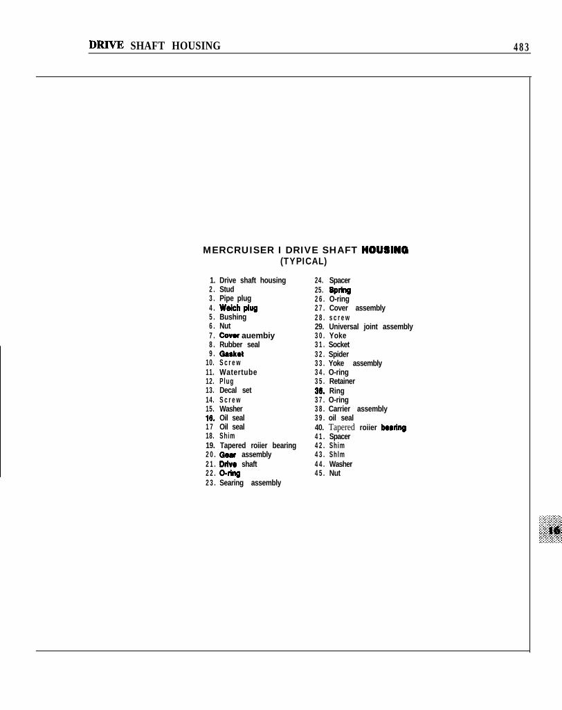
MODEL I DRIVE
Figure 1 is an exploded view of the Model Idrive shaft housing. Figure 2 is a cross-section ofthe Model I Drive to provide componentrelationships inside the drive shaft housing.
Troubleshooting
Water Shutter Clatter
Owners of MCM 898R/228R/260R models mayencounter a clattering noise at idle rpm. The noisecan be eliminated by installing a new water shutterkit (part No. 99370A2) at the top of each exhaustcollector pipe. The modification can be madewithout removing the engine from the boat.
Universal Joint Bellows Chafing
Excessive exhaust gas backpressure with MCM898R/228R/260R/200R/230MR/260MR m o d e l smay cause the exhaust bellows to balloon. Whenthis happens, the exhaust bellows pushes theuniversal joint bellows against the moving U-jointsand results in excessive chafing and prematurefailure. The problem can be eliminated byreplacing the exhaust bellows with exhaust tubepart No. 78458Al. Models manufactured after July1985 have this exhaust tube installed at the factory.
The service life of a universal joint bellows canbe extended considerably on TRTRS models usedin applications where continuous steering cycling isrequired. Lubricate the outer surface of the bellowswith Quicksilver 2-4-C Multi-Lube (part No.92-90018Al2) every 50 hours of operation or 30days.
Universal Joint Knocking(Model I, TR or TRS Drive)
Excessive side-to-side play in the U-joint crossand bearing assemblies can cause a knock orvibration during turning or trimming maneuvers.
If the original cross and bearing assembly has notbeen replaced, the problem can be eliminated byinstalling C-ring kit part No. 53- 12067Al. TheC-rings are curved at the ends and must beinstalled as shown in Figure 3 with the curve facingthe yoke or center socket.
If the original assembly has been replaced, theC-ring kit cannot be installed. The bearing capgrooves in service replacement Spicer assembliesare too narrow to accept the new C-rings.
Drive Shaft HousingRemoval
1. Remove the lower unit or gear housing. SeeChapter Fifteen.2. Loosen the forward mounting nuts on each trimcylinder.
N O T EIf the anchor pin rotates in the housing duringStep 3, remove one nut, hold the pin with ViseGrips and then remove the other nut.
3. Remove the nuts and washer at the aft end ofeach trim cylinder (Figure 4).4. Disconnect and remove the continuity springs,if so equipped. See Figure 5.5. Remove each trim cylinder from the drive shafthousing anchor pin.
N O T EZf equipped with Dyna-Shocks, removeshock-to-housing bolt on each side and movereverse lock hook release lever to RELEASEposition.
10. S c r e w11. Watertube12. Plug13. Decal set14. S c r e w15. Washer16. Oil seal1 7 Oil seal18. Shim19. Tapered roiier bearing2 0 . Qear assembly2 1 . Dtlve shaft2 2 . o-llng2 3 . Searing assembly
6. Wire the cylinders up and out of the way toprevent damage.
NOTESpiral springs are used to electrically ground thetrim cylinders. On 19751978 models,nylon-coated cylinders were used instead ofsprings. This coating should be removed andspiral springs installed.
7. Place rubber bushings, washers, and spiralsprings (Figure 6) in a safe place for reassembly.8. Remove 6 elastic stop nuts and washers holdingdrive housing to bell housing.9. Shift drive unit into forward gear to allow shiftshafts to separate.
NOTEve shaft housing refuses to move in Step 9,
the drive sha$ splines may be frozen in theengine coupler or the drive shaft may be frozen tothe gimbal bearing. To remove the unit in suchcases, you must either disconnect the engine andmove it forward or remove the drive shafthousing top cover and drive the U-joint nut o$with a hammer and punch, leaving the frozendrive shaft in the bell housing.
10. Pull drive shaft housing straight back from bellhousing, then mount assembly in a suitable holdingfixture.
4 8 6 CHAPTER SIXTEEN
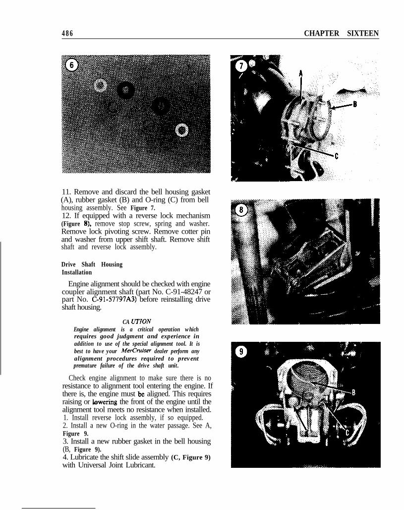
11. Remove and discard the bell housing gasket(A), rubber gasket (B) and O-ring (C) from bellhousing assembly. See Figure 7.12. If equipped with a reverse lock mechanism(Figure 8), remove stop screw, spring and washer.Remove lock pivoting screw. Remove cotter pinand washer from upper shift shaft. Remove shiftshaft and reverse lock assembly.
Drive Shaft HousingInstallation
Engine alignment should be checked with enginecoupler alignment shaft (part No. C-91-48247 orpart No. C-91-57797A3) before reinstalling driveshaft housing.
CA UTIONEngine alignment is a critical operation whichrequires good judgment and experience inaddition to use of the special alignment tool. It isbest to have your MerCruiser dealer perform anyalignment procedures required to preventpremature failure of the drive shaft unit.
Check engine alignment to make sure there is noresistance to alignment tool entering the engine. Ifthere is, the engine must be aligned. This requiresraising or lowering the front of the engine until thealignment tool meets no resistance when installed.1. Install reverse lock assembly, if so equipped.2. Install a new O-ring in the water passage. See A,Figure 9.3. Install a new rubber gasket in the bell housing(B, Figure 9).4. Lubricate the shift slide assembly (C, Figure 9)with Universal Joint Lubricant.
DRIVE SHAFT HOUSING 487
FORWARD GEAR POSITION, DRIVE UNIT
shaf t
NOTEMake sure slide is located in upright position(Figure 10) to allow slide assembly to freelyrotate on core wire. VF
5. Install a new bell housing gasket.6. Position upper shift shaft as shown in Figure 11to put drive unit in forward gear.7. Position bell housing shift mechanism as shownin Figure 12.8. Lubricate universal joint splines and O-ringswith Universal Joint Lubricant.
,F&..NOTE
Zf shaft and coupling splines do not properlyalign in Step 9, rotate propeller shaftcounterclockwise slightly until they do.
FORWARD GEAR POSITION,BELL HOUSING
Shift coupling slot
9. Guide universal joint shaft through gimbalhousing bearing and into engine drive coupling. Atthe same time, guide shift slide into opening indrive shaft housing.10. Lubricate bell housing stud threads withUniversal Joint Lubricant. Install flat washer andnew elastic stop nut on each stud. Tighten nuts tospecifications (Table 1).
CA UTZONZf spiral grounding springs and continuitysprings are not properly installed in Step I1 andStep 12, the piston rod/end assemblies will notbe grounded and can be damaged by galvaniccorrosion.
11. Make sure aft anchor pin is centered in driveshaft housing. Install large ID flat washer, rubber
1;. bushing (small diameter outward) and spiral:+: ground spring on each end of pin. Swing each tilt
cylinder up and locate pivot end on anchor pin.12. Install continuity spring with long end locatedon anchor pin between flat washer and bushing.Clamp other end over tilt cylinder piston rod.13. Install rubber bushing (small end inward) andsmall ID flat washer on each anchor pin. Wipe pinthreads with Universal Joint Lubricant and installnew elastic stop nuts.14. Tighten forward and aft anchor pin nuts untilabout 2 threads on pin are exposed beyond nut.15. Install lower gear housing. See Chapter Fifteen.
4 8 8 CHAPTER SIXTEEN
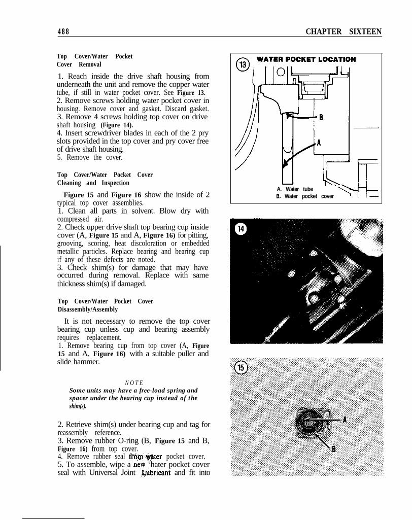
Top Cover/Water PocketCover Removal
1. Reach inside the drive shaft housing fromunderneath the unit and remove the copper watertube, if still in water pocket cover. See Figure 13.2. Remove screws holding water pocket cover inhousing. Remove cover and gasket. Discard gasket.3. Remove 4 screws holding top cover on driveshaft housing (Figure 14).4. Insert screwdriver blades in each of the 2 pryslots provided in the top cover and pry cover freeof drive shaft housing.5. Remove the cover.
Top Cover/Water Pocket CoverCleaning and Inspection
Figure 15 and Figure 16 show the inside of 2typical top cover assemblies.1. Clean all parts in solvent. Blow dry withcompressed air.2. Check upper drive shaft top bearing cup insidecover (A, Figure 15 and A, Figure 16) for pitting,grooving, scoring, heat discoloration or embeddedmetallic particles. Replace bearing and bearing cupif any of these defects are noted.3. Check shim(s) for damage that may haveoccurred during removal. Replace with samethickness shim(s) if damaged.
Top Cover/Water Pocket CoverDisassembly/Assembly
It is not necessary to remove the top coverbearing cup unless cup and bearing assemblyrequires replacement.1. Remove bearing cup from top cover (A, Figure15 and A, Figure 16) with a suitable puller andslide hammer.
N O T ESome units may have a free-load spring andspacer under the bearing cup instead of theshim(s).
2. Retrieve shim(s) under bearing cup and tag forreassembly reference.3. Remove rubber O-ring (B, Figure 15 and B,Figure 16) from top cover.4. Remove rubber seal fro,m,+$ter pocket cover.5. To assemble, wipe a neti ‘hater pocket coverseal with Universal Joint &ubricant and fit into
A. Water tubeB. Water pocket cover I-
DRIVF, SHAFT HOUSING 4 8 9
. ,o19
cover, aligning seal retaining embossment withpocket cover hole.6. Install shim(s) in top cover bearing cup bore.7. Install bearing cup with a suitable driver.8. Install a new top cover O-ring.
Top Cover/Water PocketCover Installation
If the unit has been disassembled beyond topcover removal, it should not be reinstalled until theuniversal joint and drive gear/bearing assemblyhave been installed and drive gear clearance hasbeen checked. See Drive Gear Clearance in thischapter.1. Install water pocket cover in drive shaft housingwith a new gasket. Tighten screws to specifications(Table 1).2. Install water tube to water pocket cover.3. Install top cover and tighten screws tospecifications (Table 1).
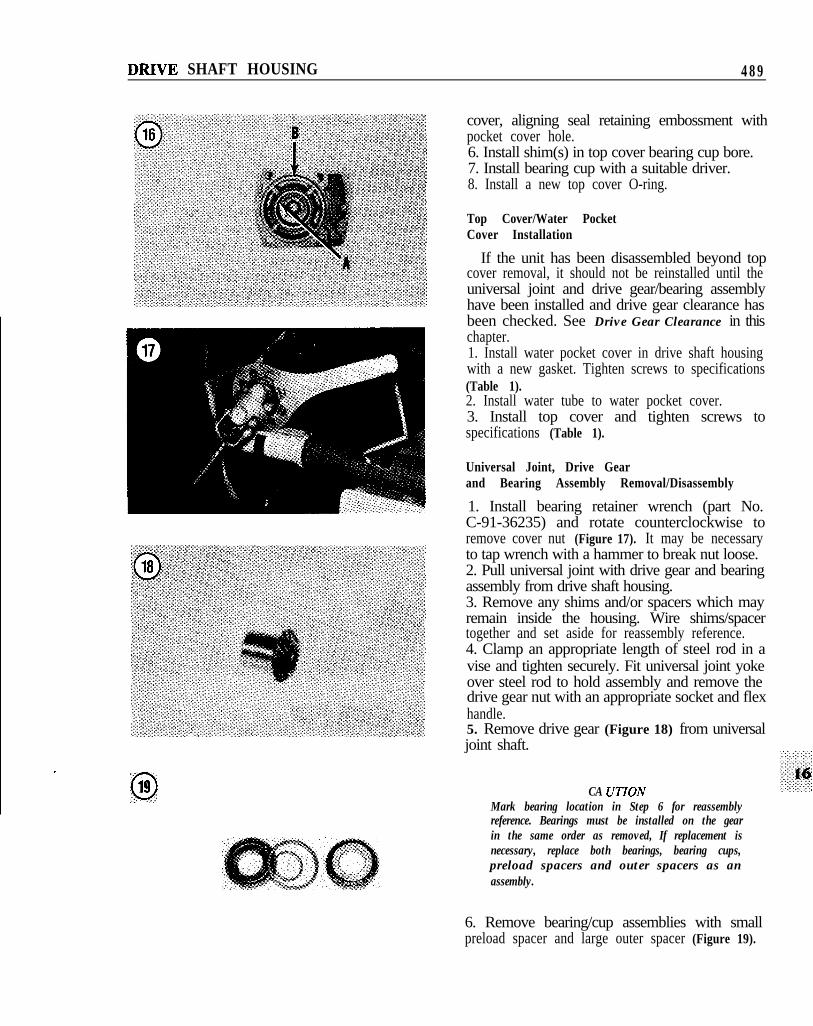
1. Install bearing retainer wrench (part No.C-91-36235) and rotate counterclockwise toremove cover nut (Figure 17). It may be necessaryto tap wrench with a hammer to break nut loose.2. Pull universal joint with drive gear and bearingassembly from drive shaft housing.3. Remove any shims and/or spacers which mayremain inside the housing. Wire shims/spacertogether and set aside for reassembly reference.4. Clamp an appropriate length of steel rod in avise and tighten securely. Fit universal joint yokeover steel rod to hold assembly and remove thedrive gear nut with an appropriate socket and flexhandle.5. Remove drive gear (Figure 18) from universaljoint shaft.
CA UTIONMark bearing location in Step 6 for reassemblyreference. Bearings must be installed on the gearin the same order as removed, If replacement isnecessary, replace both bearings, bearing cups,preload spacers and outer spacers as anassembly.
6. Remove bearing/cup assemblies with smallpreload spacer and large outer spacer (Figure 19).
4 9 0 CHAPTER SIXTEEN
7. Remove oil seal carrier, O-ring and retainer ring(Figure 20). Remove inner oil seal from carrier.8. Remove 2 O-rings from end of universal shaftcoupling (Figure 21).
Universal Joint, Drive Gearand Bearing Cleaning and Inspection
1. Clean all parts in fresh solvent. Blow dry withcompressed air.
NOTEIf wear or corrosion is found in Step 2 or Step 3,also check engine coupling splines for the samedefect.
2. Inspect coupling and gear end of U-joint forspline wear.3. Clean all corrosion from the coupling. Replacecoupling yoke if splines are partially corrodedaway.4. Check drive gear for pitting, excessive wear andchipped or broken teeth. See Figure 18. Replacegear if any of these defects are noted.5. Inspect bearing cups for pitting, scoring,grooving, heat discoloration or embedded metallicparticles. Replace bearing and cup if any defect isnoted.
020
6. Check condition of shim(s). Replace any thatare damaged.
Universal JointDisassembly/Assembly
While universal joint disassembly may not beabsolutely necessary, it is always a good idea toreplace the spider and bearings whenever the driveshaft is out of the housing.1. Support the yoke between a pair of appropriatesize sockets. Remove the snap rings with a punch(Figure 22).2. Press on one bearing until the opposite bearingis pressed into the socket, then remove the one freebearing.3. Turn the universal joint assembly 180’ andpress on bearing crossmember to remove oppositebearing.
DRIVE SHAFT HOUSING 491
4. Repeat Steps 1-3 to remove the remainingbearings. Remove the spider.
5. Repeat Steps 1-4 to remove the secondspider/yoke assembly.6. Place the new bearing cups in the yoke cavitiesand position the spider inside the yoke with thegrease fitting pointing toward the longer shaft. SeeFigure 23.
7. Press the bearings through the yoke and ontothe spider. Install new bearing snap rings. SeeFigure 24.
8. Repeat Step 6 and Step 7 to install theremaining bearings.9. Repeat Steps 6-8 to install the secondspider/yoke assembly.
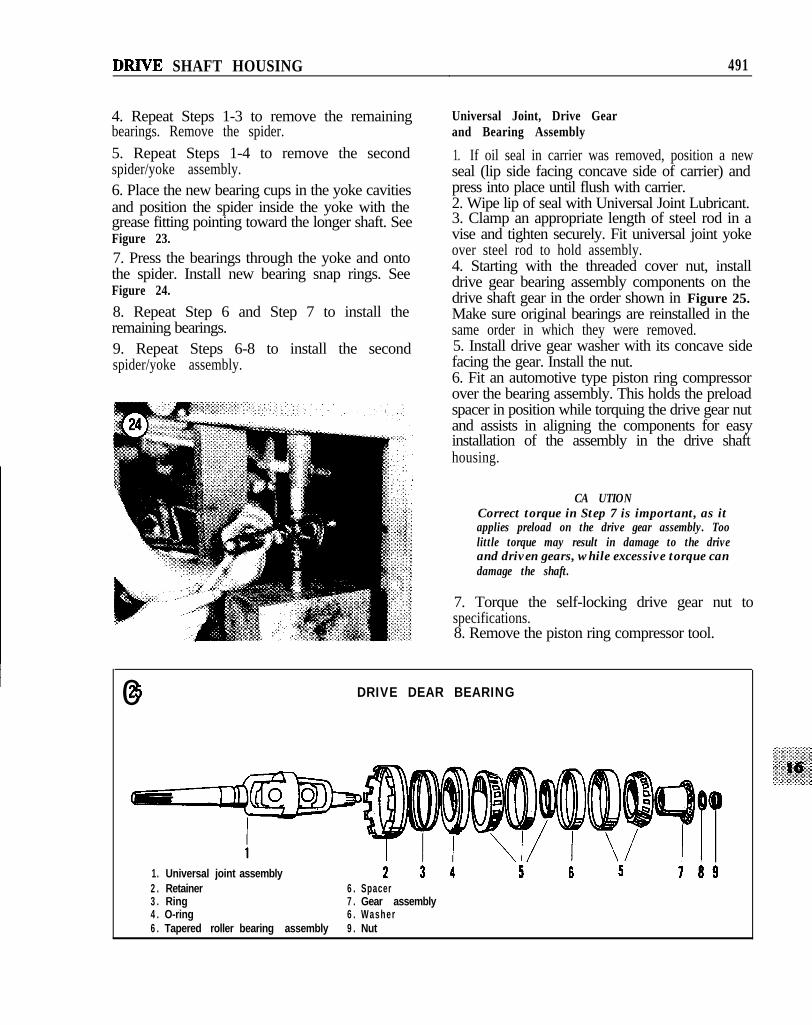
Universal Joint, Drive Gearand Bearing Assembly
1. If oil seal in carrier was removed, position a newseal (lip side facing concave side of carrier) andpress into place until flush with carrier.2. Wipe lip of seal with Universal Joint Lubricant.3. Clamp an appropriate length of steel rod in avise and tighten securely. Fit universal joint yokeover steel rod to hold assembly.4. Starting with the threaded cover nut, installdrive gear bearing assembly components on thedrive shaft gear in the order shown in Figure 25.Make sure original bearings are reinstalled in thesame order in which they were removed.5. Install drive gear washer with its concave sidefacing the gear. Install the nut.6. Fit an automotive type piston ring compressorover the bearing assembly. This holds the preloadspacer in position while torquing the drive gear nutand assists in aligning the components for easyinstallation of the assembly in the drive shafthousing.
CA UTIONCorrect torque in Step 7 is important, as itapplies preload on the drive gear assembly. Toolittle torque may result in damage to the driveand driven gears, while excessive torque candamage the shaft.
7. Torque the self-locking drive gear nut tospecifications.8. Remove the piston ring compressor tool.
Universal Joint, Drive Gearand Bearing Installation1. Remove the top cover as described in thischapter.2. Install bearing cup-to-gear housing shim(s) andspacer in drive shaft housing.
CA UTIONMerCruiser drive units with a 1.65:1 ratio havethe same number of teeth on drive and drivengears in the drive shaft housing. These gearshave marks that must be aligned as shown inFigure 26.
3. Align gear marks, if necessary, and installuniversal joint/drive gear assembly into drive shafthousing.4. Install bearing retainer wrench (part No.C-91-36235) (Figure 17) and tighten cover nut tospecifications (Table 1).5. Check drive-to-driven gear clearance asdescribed under Drive Gear Cleurunce in thischapter.6. When clearance is correct, install top cover andtighten to specifications (Table 1).
Upper Drive Shaft/Driven Gear Assembly Removal
1. Remove top cover/water pocket cover asdescribed in this chapter.2. Remove universal joint, drive gear and bearingassembly as described in this chapter.3. Reach into drive shaft housing and remove theupper drive shaft and driven gear/bearingassembly.4. Press the upper drive shaft (Figure 27) from thedriven gear/bearing (Figure 28).
Upper Drive Shaft/Driven GearAssembly Cleaning and Inspection
1. Check driven gear for signs of pitting, worn,chipped or broken teeth. Replace as required.2. Check tapered roller bearing cup for signs ofscoring, pitting, grooving, heat discoloration orembedded metallic particles. Replace bearing and
in> if any of these defects are noted.* ’ 3. Check driven gear shaft surface where oil seal
lip rides. Replace gear/shaft assembly if area showsany signs of grooving.4. Replace O-ring on lower end of upper driveshaft (arrow, Figure 27).
1. Wipe ID of driven gear with Universal JointLubricant, then press upper drive shaft into drivengear.2. Wipe ID of driven gear tapered roller bearing (ifremoved) and press into place until it seats onshoulder of driven gear.3. Install upper drive shaft and driven gearassembly into drive shaft housing.
DRIVE SHAFT HOUSING 4 9 3
SIIIMMINQ TOOL (C-SlaOS23)
I Tool poritlcml x 1 Y 1 2 1
4. Establish upper drive shaft bearing preload asdescribed in this chapter.5. Check driven gear clearance as described in thischapter.6. Install universal joint, drive gear and bearingassembly as described in this chapter.7. Install top cover/water pocket cover asdescribed in this chapter.
Intermediate Shift Shaft/SealRemoval/Installation
1. Remove the drive shaft housing as described inthis chapter.2. Invert the housing and install in a suitableholding fixture.
3. Remove the intermediate shift shaft cotter pin(arrow, Figure 29). Remove the washer and shiftshaft.4. Drive the shift shaft bushing out with anappropriate size socket and hammer.5. Installation is the reverse of removal.
Drive Shaft Housing Bearing Cups
Whenever the drive shaft housing is completelydisassembled, wash the entire assembly in solventand blow dry with compressed air. If one or morebearing cups and/or oil seals must be replaced, theycan be removed with a standard 2-jaw puller andslide hammer (bearing cups) or screwdriver (oilseals) and installed with appropriate size sockets ordrivers. Be sure to retrieve any shims located underthe bearing cup.
Wipe the OD of all oil seals with Loctite Type Abefore installation. Install the upper and lowerdrive shaft oil seals with their lip facing the drivengear. After installation, lubricate seal lip withUniversal Joint Lubricant.
Drive Gear Clearance
Whenever the universal joint, drive gear andbearing assembly is removed, drive gear clearancemust be checked and corrected as the unit isreassembled. This procedure requires the use of thefollowing shimming tool according to model:
No. C-91-45877.e. MerCruiser 120, 140, 165, 888 (late) and
I-MR-part No. C-91-60523.1. Refer to Figure 30, which shows the specialshimming tool required and how it is used. Select 1- ‘, i 4the proper face of the shimming tool to be used !,I”’ eaccording to your drive unit (Figure 30). Align that ; g , ,, /face with 2-3 teeth of the driven gear.2. Insert an 0.025 in. flat feeler gauge between oneouter tooth of the aligned gear teeth and theshimming tool.3. Rotate shimming tool to provide slight drag onfeeler gauge. Hold shimming tool in position andmove feeler gauge between the other outer tooth ofthe aligned gear teeth and the tool.4. If clearance is greater or smaller than 0.025 in.,repeat Step 2 and Step 3 with feeler gauges of
494 CHAPTER SIXTEEN
varying thickness until the same clearance is feltbetween both outer teeth and the tool!5. If clearance is less than 0.025 in., subtract yourreading from 0.025 in. The difference is the shimthickness to be added between the drive shafthousing and the universal joint bearing cup.6. If clearance is greater than 0.02 in., subtract0.025 in. from your reading. The difference is theshim thickness to be removed from between thedrive shaft housing and the universal joint bearingcup.7. After making the necessary calculations andchanging shims as required, repeat this procedureto make sure drive gear clearance is now correct.When it is, you may continue unit reassembly.
Driven Gear Clearance
This procedure requires the use of the followingshimming tool according to model:
No. C-91-45878.e. MetCruiser 120, 140, 165, 888 (late) and I-
MR-part No. C-91-60526.
j1. Check the upper drive shaft bearing preload asdescribed in this chapter.2. Check that top cover is properly torqued inposition.3. Select the proper face of the shimming tool to beused according to your drive unit (Figure 31). Alignthat face with 3 teeth of the driven gear.4. Insert an 0.025 in. flat feeler gauge as shown inFigure 31 between one outer tooth of the alignedgear teeth and the shimming tool.5. Rotate shimming tool to provide slight drag onfeeler gauge. Hold shimming tool in position andmove feeler gauge between another outer tooth ofthe aligned gear teeth and the tool.6. If clearance is greater or smaller than 0.025 in.,repeat Step 4 and Step 5 with feeler gauges ofvarying thickness until the same clearance is feltbetween both outer teeth and the tool.7. If clearance is less than 0.025 in., subtract yourreading from 0.025 in. The difference is the shimthickness that must be removed from under thedriven gear tapered roller bearing cup. The sameamount of shimming must be added under theupper drive shaft bearing cup in the top cover tomaintain upper drive shaft preload.
MEASURINQ DRIVEN DEAR CLEARANCE
SHIMMINQ TOOL (C.91=60526)
I Tool position I x I Y lzl
I Drive unit model 1 165 1 120-140-470 1 V8 1
8. If clearance is greater than 0.025 in., subtract0.025 in. from your reading. The difference is theshim thickness that must be added under thedriven gear tapered roller bearing cup. The sameamount of shimming must be removed from underthe upper drive shaft bearing cup in the top coverto maintain upper drive shaft preload.
Upper Drive Shaft Bearing Preload
The lower gear housing must be removed fromthe drive shaft housing for this check.1. Mount gear housing in a suitable holdingfixture.2. Lubricate all bearings and gears involved with afew drops of Quicksilver Super-Duty GearLubricant (part No. C-92-686 17) to prevent erraticresults from dry bearings and gears.3. Rotate drive shaft several times in one directionto set the bearings.4. Install an inch-pound torque wrench to the endof the drive shaft and slowly rotate the shaft in the
DRIVE SHAFT HOUSING 495
same direction as in Step 3. Maintain a smoothrotational motion and note torque reading. Itshould be between 6- 10 in.-lb. for new bearings and2 l/2-4 in.-lb. for used bearings.
NOTEIf top cover bearing cup shimming is changed,the cover must be retorqued and drive shaftclearance rechecked.
5. If torque reading is greater than specified,remove shims from under the top cover bearingcup. If less than specified, add shims under the topcover bearing cup.
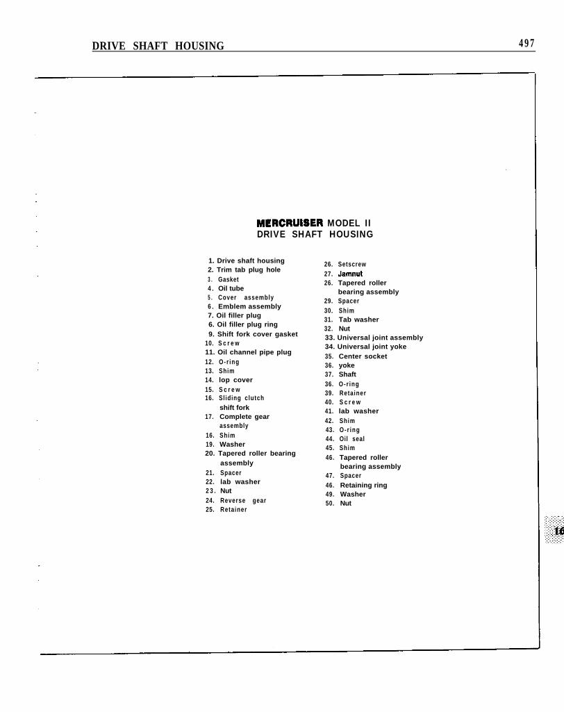
MODEL II
Figure 32 is an exploded view of the Model IIdrive shaft housing components.
Drive Shaft HousingRemoval/Installation
1. Remove the lowerFifteen.
gear housing. See Chapter
2. Disconnect the shift cable.3. Loosen 2 square head setscrews. Pull guide awayfrom cable.4. Loosen hex head jamnut on end of cable. Screwinsert out and remove.5. Loosen universal joint and shift cable bellowshose clamps at gimbal housing. Carefully slidebellows away from gimbal housing.6A. 1.33:1 drive-Remove shock absorber anchorbolt and rotate unit to vertical position.6B. 1.78:1 drive-Remove trim cylinders.
NOTEIn Step 7, some models use cotter pins instead ofretaining pins.
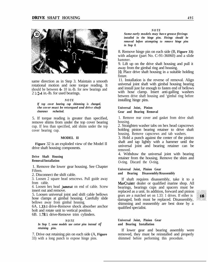
7. Drive out retaining pin on each side (A, Figure33) with a long punch to expose hinge pins.
NOTESome early models may have grease fittingsinstalled in the hinge pins. Fittings should beremoved before attempting to remove hinge pinsin Step 8.
8. Remove hinge pin on each side (B, Figure 33)with adaptor (part No. C-91-36060) and a slidehammer.9. Lift up on the drive shaft housing and pull itaway from the gimbal ring and housing.10. Place drive shaft housing in a suitable holdingfixture.11. Installation is the reverse of removal. Alignuniversal joint shaft with gimbal housing bearingand install just far enough to fasten end of bellowswith hose clamp. Insert anti-galling washersbetween drive shaft housing and ‘gimbal ring beforeinstalling hinge pins.
Universal Joint, PinionGear and Bearing Removal
1. Remove rear cover and gasket from drive shafthousing.2. Straighten washer tabs on hex head capscrewsholding pinion bearing retainer to drive shafthousing. Remove capscrews and tab washers.3. Hold a punch against the center of the pinionshaft and tap lightly with a hammer until theuniversal joint and bearing retainer can beremoved.4. Withdraw the universal joint with bearingretainer from the housing. Remove the shim andO-ring. Discard the O-ring.
If shaft requires disassembly, take it to aMerCruiser dealer or qualified marine shop. Allbearings, bearings cups and spacers must bereplaced as a unit. In addition, forward and piniongears are a matched set on 1.33: 1 drives. If either isdamaged, both must be replaced. Disassembly,shimming and reassembly are best done by aqualified specialist.
There is a mark on the lower gear on 1.33: 1drives with left-hand rotation and 20 degree spiralangle gear teeth and on all units with 35 degreespiral angle gear teeth. On such units, the markedtooth on the lower gear must mesh between the 2marked pinion gear teeth.1. Install pinion gear and universal joint assemblywith shim and a new O-ring into drive shafthousing.2. Align holes in bearing retainer, shim andhousing. Install capscrews with tab washers.Tighten capscrews to specifications (Table 1) andbend one tab up on each washer.3. Install rear cover with new gasket. Tightenscrews to specifications (Table 1).
Upper Gear and Bearing Removal
1. Remove top cover plate screws. Tap lightly onthe underside of the cover with a plastic mallet tobreak the seal. Remove the cover, shim(s) andO-ring. Discard the O-ring.2. Remove the upper gear and bearing assembly.
Upper Gear and BearingDisassembly/Reassembly
If shaft requires disassembly, take it to aMerCruiser dealer or qualified marine shop. Allbearings, bearings cups and spacers must bereplaced as a unit. Disassembly, shimming andreassembly are best done by a qualified specialist.
Upper Gear and BearingInstallation
1. Perform Upper Gear Bearing Assembly DriveShaft Housing Clearance as described in thischapter.2. After correct shim thickness has beendetermined, measure gap between top cover anddrive shaft housing with a flat feeler gauge.3. Remove cover from housing and install shimsthat are 0.002 in. thinner than the feeler gaugereading obtained in Step 2.
NOTEModels with serial No. 1602186 and above useoil passages in the drive shaft housing and topcover assembly, Check to make sure thesepassages are clean before installing cover in Step4.
4. Reinstall cover with shim(s) and new O-ring.Tighten fasteners to specifications (Table 1).
Lower Gear and BearingAssembly Removal
This procedure requires the use of many specialtools. Bearings are matched and a complete set ofbearings, cups and spacers must be installed ifexisting bearing set is damaged. For this reason, itis probably best that you have this procedureperformed by a MerCruiser dealer or otherqualified specialist.1. Place an old sliding clutch on top of the lowergear. Make sure clutch lugs engage gear lugs.2. Install splined end of wrench adaptor (part No.C-91-32332Al) into center of sliding clutch. Installbolt and washer from bottom of drive shafthousing and tighten into adaptor. Make surewasher is centered on gear and does not touchlocknut when tightening bolt.3. Install top cover holding fixture (part No.C-91-32333Al) over adaptor and fasten to driveshaft housing.
NOTEOn early units, a large screwdriver blade can be
jammed in one of the locknut cutouts and usedto hold the assembly from turning.
4. Install gear locknut wrench (part No.C-91-32329) with flex handle and 6 in. extensionfrom underneath unit until it engages and holdslocknut at bottom of lower gear/bearing assembly.5. Turn wrench adaptor counterclockwise to breaklocknut free. Remove retaining bolt and washer,then finish removing locknut.6. Remove pilot plate, wrench adaptor and slidingclutch.7. Remove the gear, one tapered roller bearing andspacer from drive shaft housing.8. Remove jamnuts and setscrews holding bearingcup retainer in place.9. Install lugs of retainer driver (part No.C-9 l-35545) into retainer notches.10. Install drive end of wrench adaptor tool intodriver with spacer furnished.11. Place holding fixture (part No. C-91-32333A)over the adaptor. Secure it to drive shaft housing,then rotate adaptor counterclockwise until retainercan be removed.12. Remove bearing, cups and shims from housingwith a bearing puller (part No. C-91-3 1229A4).
DRIVE SHAFT HOUSING 499
Installation
1. Perform Upper Gear/Bearing Assembly DriveHousing Clearance procedure.2. Install bearing assemblies on lower gear asfollows: large diameter of tapered roller bearingtoward gear, bearing cup on roller bearing, spacers,bearing cup with large diameter facing upward androller bearing in cup.3. Install gear locknut finger-tight.4. Install shim(s) in drive shaft housing.5. Press gear and bearing assembly into drive shafthousing until it bottoms.6. Remove locknut from gear. Lift gear, taperedroller bearing and spacers from drive shaft housing.7. Install bearing retainer with retainer driver (partNo. C-91-35545), wrench adaptor (part No.C-91-32332Al) and holding fixture (part No.C-91-32333Al).8. Position tapered roller bearing and spacer(s) onlower gear, then install assembly in bearing cupinside the drive shaft housing.9. Install locknut on underside of gear/bearingassembly with chamfer facing up.10. Install an old sliding clutch on the gear withthe clutch teeth engaging the gear teeth.11. Install retaining bolt and washer through gearand tighten into wrench adaptor. Make sure washeris centered on gear and does not touch locknutwhen tightening the bolt.12. Install gear locknut wrench (part No.C-91-32329) from bottom of unit to hold gearlocknut. Turn wrench adaptor clockwise to tightennut to 150 ft.-lb.13. If new gears and/or bearing assemblies wereinstalled, perform Lower Gear/Bearing AssemblyClearance procedure in this chapter.14. Swage locknut in place with tool part No.C-91-53122.
This procedure must be performed before thelower gear and bearing assembly is reinstalled inthe drive shaft housing.1. Install shimming tool (part No. C-91-52001) indrive shaft housing through pinion retaineropening. Plat surface must clear upper gear.2. Reinstall shims in drive shaft housing.3. Install top cover without O-ring or cover shims.Tighten cover snugly; do not torque.
4. Rotate shimming tool until you can measure thegap between the rounded tool surface and the flatsurface on a tooth with a feeler gauge:
a. Early 1.33:1 drives with 35” spiral angle gearsshould have a clearance of 0.032 in.
b. Late 1.33: 1 and all 1.78: 1 drives with 20spiral angle gears should have a clearance of0.025 in.
5. If clearance between tool and tooth gear isexcessive, remove sufficient shimming from driveshaft cover to bring it into specifications.6. If clearance is too small, add shimming to driveshaft cover to bring it into specifications.7. Proceed with Lower Gear and BearingAssembly/Znstallation as described in this chapter.
Lower Gear/BearingAssembly Clearance
This procedure must be performed whenever anew lower gear or bearing assemblies are installed.1. Install shimming tool (part No. C-91-52001) indrive shaft housing through pinion retaineropening. Flat surface must clear lower gear.2. Rotate shimming tool until you can measure thegap between the rounded tool surface and the flatsurface on a tooth with a feeler gauge:
a. Early 1.33:l drives with 35” spiral angle gearsshould have a clearance of 0.032 in.
b. Late 1.33:l and all 1.78:l drives with 20spiral angle gears should have a clearance of0.025 in.
3. If clearance between tool and tooth gear isexcessive, add sufficient shimming under thebottom bearing cup to bring it into specifications.4. If clearance is too small, remove shimmingfrom under bottom bearing cup to bring it intospecifications.
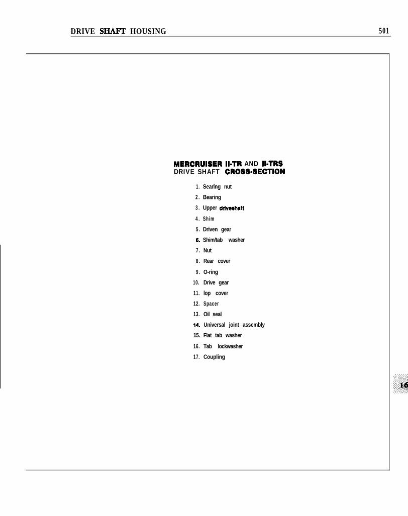
MODEL II-TR AND II-TRS DRIVE
Figure 34 is a cross-section of the ModelII-TR/II-TRS drive to show componentrelationships within the drive shaft housing.
Drive Shaft HousingRemoval/Installation
The II-TR and II-TRS drive shaft housing canbe removed following the procedure given in thischapter for the Model I.
500 CHAF’TER SIXTEEN
DRIVE SHAFI’ HOUSING 501
MERCRUISER II=TR AND IbTRSDRIVE SHAFT CROSS=SECTION
1. Searing nut
2 . Bearing
3 . Upper driweshatt
4 . Shim
5 . Driven gear
6. Shim/tab washer
7 . Nut
8 . Rear cover
9 . O-ring
10. Drive gear
11. lop cover
12. Spacer
13. Oil seal
14. Universal joint assembly
15. Flat tab washer
16. Tab lockwasher
17. Coupling
5 0 2 CHAPTER SIXTEEN
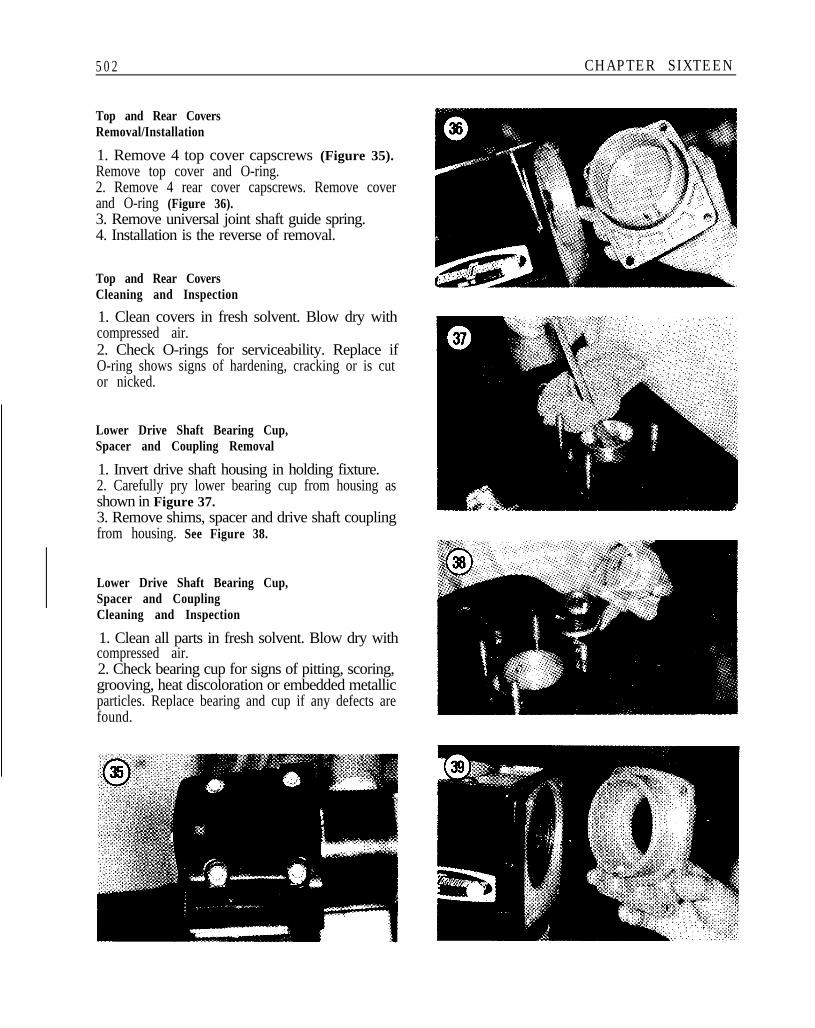
Top and Rear CoversRemoval/Installation
1. Remove 4 top cover capscrews (Figure 35).Remove top cover and O-ring.2. Remove 4 rear cover capscrews. Remove coverand O-ring (Figure 36).3. Remove universal joint shaft guide spring.4. Installation is the reverse of removal.
Top and Rear CoversCleaning and Inspection
1. Clean covers in fresh solvent. Blow dry withcompressed air.2. Check O-rings for serviceability. Replace ifO-ring shows signs of hardening, cracking or is cutor nicked.
Lower Drive Shaft Bearing Cup,Spacer and Coupling Removal
1. Invert drive shaft housing in holding fixture.2. Carefully pry lower bearing cup from housing asshown in Figure 37.3. Remove shims, spacer and drive shaft couplingfrom housing. See Figure 38.
Lower Drive Shaft Bearing Cup,Spacer and CouplingCleaning and Inspection
1. Clean all parts in fresh solvent. Blow dry withcompressed air.2. Check bearing cup for signs of pitting, scoring,grooving, heat discoloration or embedded metallicparticles. Replace bearing and cup if any defects arefound.
DRIVE SHAFT HOUSING 5 0 3
3. Check shims for damage. Replace any that arenot serviceable with new shims of the samethickness.4. Inspect coupling splines for signs of excessivewear, rust or pitting.
Lower Drive Shaft Bearing Cup,Spacer and Coupling Installation
1. With drive shaft housing inverted, install driveshaft coupler, spacer and shims (Figure 38).2. Install bearing cup in drive shaft housing with asoft mallet.
Universal Joint andDrive Gear Removal
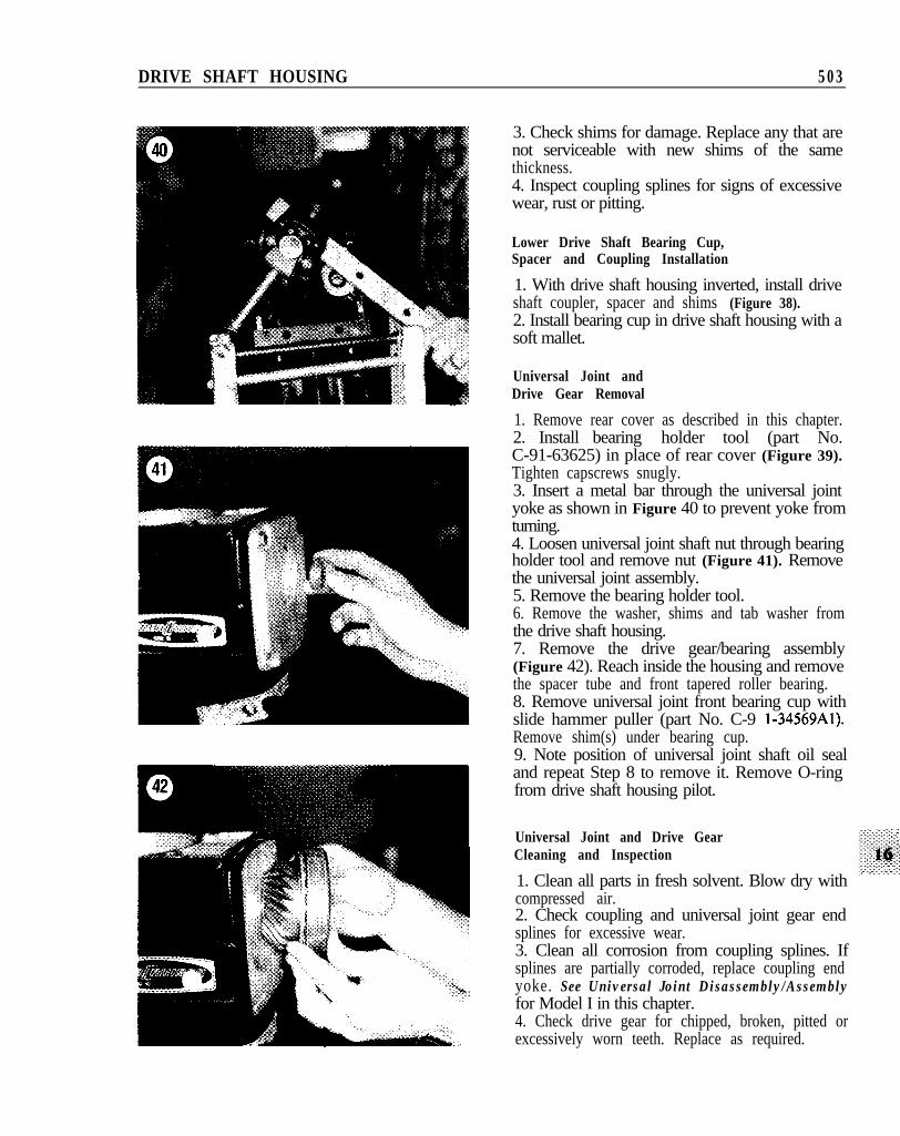
1. Remove rear cover as described in this chapter.2. Install bearing holder tool (part No.C-91-63625) in place of rear cover (Figure 39).Tighten capscrews snugly.3. Insert a metal bar through the universal jointyoke as shown in Figure 40 to prevent yoke fromturning.4. Loosen universal joint shaft nut through bearingholder tool and remove nut (Figure 41). Removethe universal joint assembly.5. Remove the bearing holder tool.6. Remove the washer, shims and tab washer fromthe drive shaft housing.7. Remove the drive gear/bearing assembly(Figure 42). Reach inside the housing and removethe spacer tube and front tapered roller bearing.8. Remove universal joint front bearing cup withslide hammer puller (part No. C-9 l-34569Al).Remove shim(s) under bearing cup.9. Note position of universal joint shaft oil sealand repeat Step 8 to remove it. Remove O-ringfrom drive shaft housing pilot.
Universal Joint and Drive GearCleaning and Inspection
1. Clean all parts in fresh solvent. Blow dry withcompressed air.2. Check coupling and universal joint gear endsplines for excessive wear.3. Clean all corrosion from coupling splines. Ifsplines are partially corroded, replace coupling endyoke. See Universal Joint Disassembly/Assemblyfor Model I in this chapter.4. Check drive gear for chipped, broken, pitted orexcessively worn teeth. Replace as required.
5 0 4 CHAPTER SIXTEEN
5. Check bearing cups for signs of pitting, scoring,grooving, heat discoloration or embedded metallicparticles. Replace bearing and cup if any of thesedefects are noted.6. Check O-ring for serviceability. Replace if cut,nicked, cracked or hardened.7. Check oil seal for signs of wear, damage,roughness or improper spring position. Replace asrequired.
Universal Joint andDrive Gear Installation
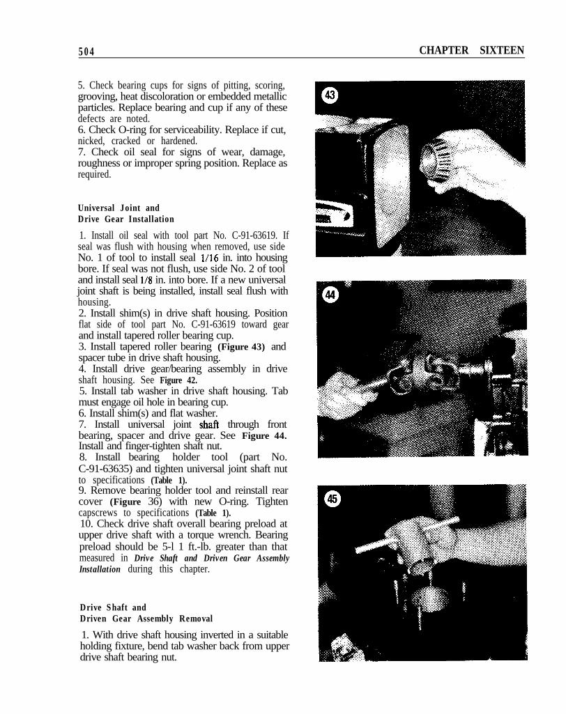
1. Install oil seal with tool part No. C-91-63619. Ifseal was flush with housing when removed, use sideNo. 1 of tool to install seal l/16 in. into housingbore. If seal was not flush, use side No. 2 of tooland install seal l/8 in. into bore. If a new universaljoint shaft is being installed, install seal flush withhousing.2. Install shim(s) in drive shaft housing. Positionflat side of tool part No. C-91-63619 toward gearand install tapered roller bearing cup.3. Install tapered roller bearing (Figure 43) andspacer tube in drive shaft housing.4. Install drive gear/bearing assembly in driveshaft housing. See Figure 42.5. Install tab washer in drive shaft housing. Tabmust engage oil hole in bearing cup.6. Install shim(s) and flat washer.7. Install universal joint shaft through frontbearing, spacer and drive gear. See Figure 44.Install and finger-tighten shaft nut.8. Install bearing holder tool (part No.C-91-63635) and tighten universal joint shaft nutto specifications (Table 1).9. Remove bearing holder tool and reinstall rearcover (Figure 36) with new O-ring. Tightencapscrews to specifications (Table 1).10. Check drive shaft overall bearing preload atupper drive shaft with a torque wrench. Bearingpreload should be 5-l 1 ft.-lb. greater than thatmeasured in Drive Shaft and Driven Gear AssemblyInstallation during this chapter.
Drive Shaft andDriven Gear Assembly Removal
1. With drive shaft housing inverted in a suitableholding fixture, bend tab washer back from upperdrive shaft bearing nut.
DRIVE SHAFT HOUSING 5 0 5
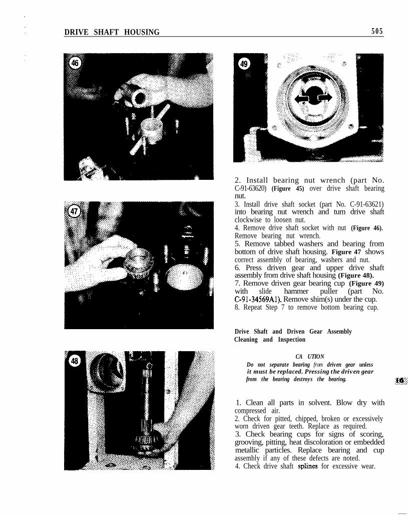
2. Install bearing nut wrench (part No.C-91-63620) (Figure 45) over drive shaft bearingnut.3. Install drive shaft socket (part No. C-91-63621)into bearing nut wrench and turn drive shaftclockwise to loosen nut.4. Remove drive shaft socket with nut (Figure 46).Remove bearing nut wrench.5. Remove tabbed washers and bearing frombottom of drive shaft housing. Figure 47 showscorrect assembly of bearing, washers and nut.6. Press driven gear and upper drive shaftassembly from drive shaft housing (Figure 48).7. Remove driven gear bearing cup (Figure 49)with slide hammer puller (part No.C-91-34569Al). Remove shim(s) under the cup.8. Repeat Step 7 to remove bottom bearing cup.
Drive Shaft and Driven Gear AssemblyCleaning and Inspection
CA UTIONDo not separate bearing from driven gear unlessit must be replaced. Pressing the driven gearfrom the bearing destroys the bearing.
1. Clean all parts in solvent. Blow dry withcompressed air.2. Check for pitted, chipped, broken or excessivelyworn driven gear teeth. Replace as required.3. Check bearing cups for signs of scoring,grooving, pitting, heat discoloration or embeddedmetallic particles. Replace bearing and cupassembly if any of these defects are noted.4. Check drive shaft splines for excessive wear.
5 0 6 CHAPTER SIXTEEN
Drive Shaft and DrivenGear Assembly Installation
1. Install driven gear bearing shim(s). Installbearing cup with driver part No. C-91-63626.2. Install upper drive shaft bearing cup with driverpart No. C-91-63619.
NOTEWasher tabs must align with drive shaft slot inStep 3. Chamfered side of nut should facebearing.
3. Install upper drive shaft through top of housing.lnstall tapered roller bearing, flat tabbed washer,new tab washer and bearing nut through bottom ofdrive shaft housing.
NOTETighten bearing nut in stages in Step 4, checkingpreload torque on the upper drive shaft with adrive shaft socket and inch-pound torque wrench.If too much torque is provided, resulting in toomuch preload, remove nut and start again. Donot back of nut to adjust torquelpreload,
4. Install drive shaft socket/wrench (part No.C-91-6362OAl) and rotate drive shaftcounterclockwise to tighten nut sufficiently toobtain the proper preload on upper drive shaftbearings.5. Align bearing nut slot with washer tab. Bend tabinto slot.
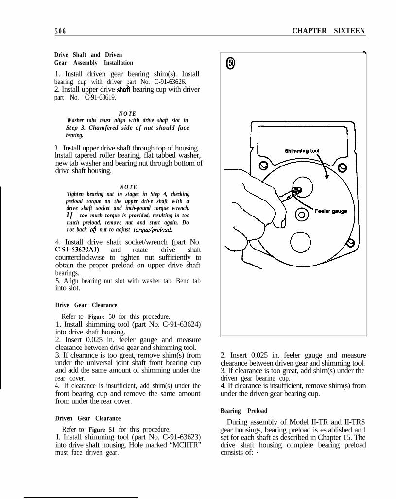
Drive Gear Clearance
Refer to Figure 50 for this procedure.1. Install shimming tool (part No. C-91-63624)into drive shaft housing.2. Insert 0.025 in. feeler gauge and measureclearance between drive gear and shimming tool.3. If clearance is too great, remove shim(s) fromunder the universal joint shaft front bearing cupand add the same amount of shimming under therear cover.4. If clearance is insufficient, add shim(s) under thefront bearing cup and remove the same amountfrom under the rear cover.
Driven Gear Clearance
Refer to Figure 51 for this procedure.I. Install shimming tool (part No. C-91-63623)into drive shaft housing. Hole marked “MCIITR”must face driven gear.
.
050
2. Insert 0.025 in. feeler gauge and measureclearance between driven gear and shimming tool.3. If clearance is too great, add shim(s) under thedriven gear bearing cup.4. If clearance is insufficient, remove shim(s) fromunder the driven gear bearing cup.
Bearing Preload
During assembly of Model II-TR and II-TRSgear housings, bearing preload is established andset for each shaft as described in Chapter 15. Thedrive shaft housing complete bearing preloadconsists of: _
DRIVE SHAFT HOUSING 507
a. The upper drive shaft preload.b. The universal joint shaft preload.
This complete preload is measured at the upperdrive shaft.
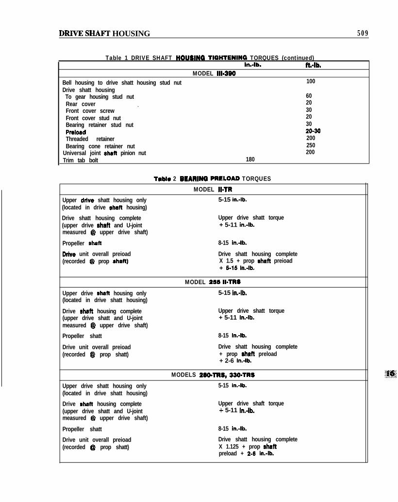
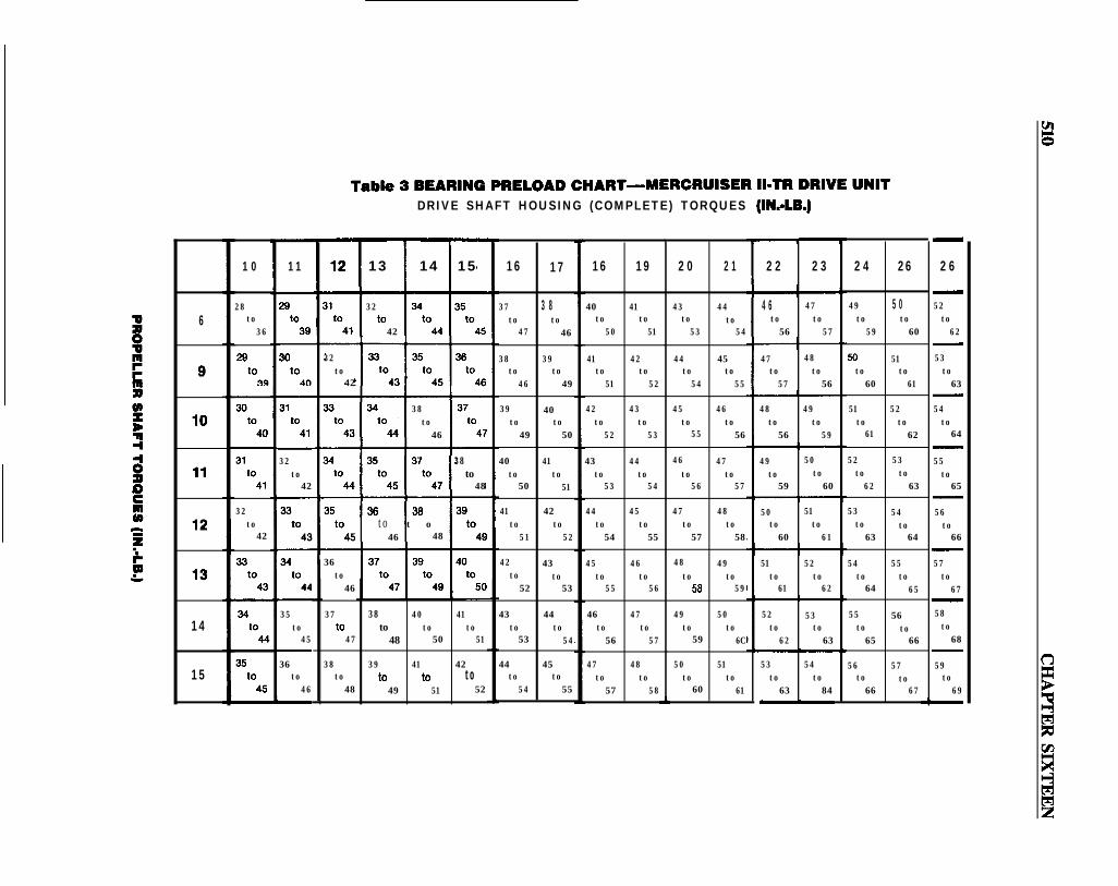
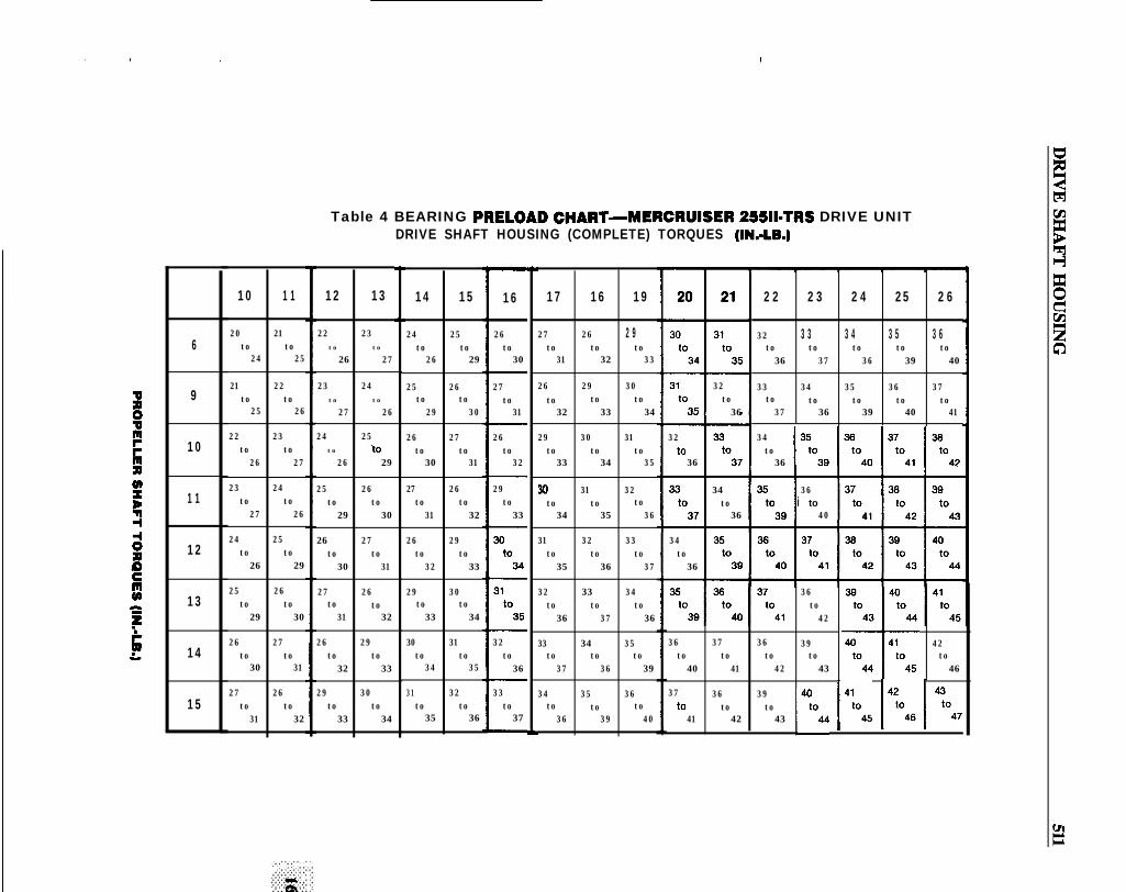
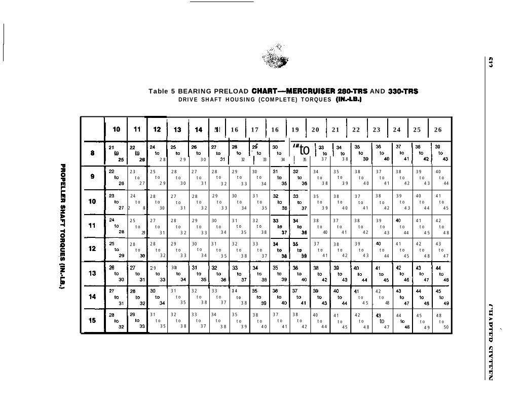
Table 2 contains bearing preload torquespecifications for MerCruiser II-TR, 25511-TRS,280-TRS and 330-TRS models. Tables 3-5 providebearing preload charts for the same models. Referto appropriate preload torque chart to determinedrive shaft housing overall bearing preload torque(top line). Locate prop shaft bearing preload torquealong left side of chart. The 2 figures in theintersecting block of the preload chart are theupper/lower limits of the drive unit’s overallbearing preload torque, as measured at the propshaft.
If the preload as measured is not within thespecified range, rotate the propeller shaft severaltimes to seat the bearings and recheck. If themeasured preload for the total unit still does notagree with the chart value, separate the housings.Recheck individual preload settings against thevalues specified in Table 2 and correct as necessary.