DI-1 DRIVER INFORMATION SYSTEM K ELECTRICAL CONTENTS C D E F G H I J L M SECTION DI A B DI Revision; 2004 April 2003 G35 Coupe DRIVER INFORMATION SYSTEM PRECAUTION ........................................................... 3 Precautions for Supplemental Restraint System (SRS) “AIR BAG” and “SEAT BELT PRE-TEN- SIONER” ................................................................. 3 Precautions for Battery Service ............................... 3 Wiring Diagrams and Trouble Diagnosis ................. 3 COMBINATION METERS .......................................... 4 System Description ................................................. 4 UNIFIED CONTROL METER ............................... 4 HOW TO CHANGE THE DISPLAY FOR ODO/ TRIP METER ....................................................... 4 POWER SUPPLY AND GROUND CIRCUIT ....... 4 WATER TEMPERATURE GAUGE ....................... 5 TACHOMETER .................................................... 5 FUEL GAUGE ...................................................... 5 SPEEDOMETER .................................................. 5 CAN Communication ............................................... 5 M/T MODELS ....................................................... 5 A/T MODELS ....................................................... 7 Component Parts and Harness Connector Location ..... 8 Combination Meter .................................................. 9 CHECK ................................................................. 9 Schematic ............................................................. 10 Wiring Diagram — METER — ................................ 11 Terminals and Reference Value for Combination Meter ..................................................................... 12 Meter/Gauges Operation and Odo/Trip Meter ....... 13 SELF-DIAGNOSIS FUNCTION ......................... 13 HOW TO ALTERNATE DIAGNOSIS MODE ...... 13 How to Proceed With Trouble Diagnosis ............... 13 Diagnosis Flow ...................................................... 14 Power Supply and Ground Circuit Check .............. 15 Trouble Diagnosis Chart by Symptom ................... 16 DIAGNOSIS RESULTS ...................................... 16 Inspection/Fuel Level Sensor ................................ 17 FUEL GAUGE .................................................... 17 LOW-FUEL WARNING LAMP ............................ 17 Inspection/Engine Speed Signal ........................... 19 Inspection/Water Temperature Signal ................... 19 Inspection/Vehicle Speed Signal ........................... 19 The Fuel Gauge Pointer Fluctuates, Indicator Wrong Value or Varies ........................................... 20 The Fuel Gauge Does Not Move to FULL Position ... 20 The Fuel Gauge Does Not Work ........................... 21 Low Fuel Warning Lamp Illuminates at All Times or Does Not Illuminate ............................................... 21 Electrical Components Inspection ......................... 22 FUEL LEVEL SENSOR UNIT CHECK ............... 22 Removal and Installation for Combination Meter ... 23 REMOVAL .......................................................... 23 INSTALLATION .................................................. 23 Disassembly and Assembly for Combination Meter ... 23 COMPASS ................................................................ 24 System Description ................................................ 24 DIRECTION DISPLAY ........................................ 24 Wiring Diagram — COMPASS — .......................... 25 Power Supply and Ground Circuit Check for Com- pass ....................................................................... 26 Fail-Safe System ................................................... 27 DESCRIPTION ................................................... 27 Compass Does not Display ................................... 27 Compass Display “– – –” ....................................... 27 Forward Direction Indication Slips Off The Mark Or Incorrect ................................................................. 29 Compass Reading Remains Unchanged .............. 29 Calibration Procedure for Compass ...................... 30 CORRECTION FUNCTIONS OF COMPASS ..... 30 INITIAL CORRECTION PROCEDURE FOR COMPASS .......................................................... 30 Removal and Installation of Compass ................... 31 REMOVAL .......................................................... 31 INSTALLATION .................................................. 31 WARNING LAMPS ................................................... 32 Schematic .............................................................. 32 Wiring Diagram — WARN — ................................. 33 Oil Pressure Warning Lamp Stays Off (Ignition Switch ON) ............................................................ 39 Oil Pressure Warning Lamp Does Not Turn Off (Oil
Transcript
DI-1
DRIVER INFORMATION SYSTEM
K ELECTRICAL
CONTENTS
C
D
E
F
G
H
I
J
L
M
SECTION DIA
B
DI
Revision; 2004 April 2003 G35 Coupe
DRIVER INFORMATION SYSTEM
PRECAUTION ............................................................ 3Precautions for Supplemental Restraint System (SRS) “AIR BAG” and “SEAT BELT PRE-TEN-SIONER” .................................................................. 3Precautions for Battery Service ................................ 3Wiring Diagrams and Trouble Diagnosis .................. 3
UNIFIED CONTROL METER ................................ 4HOW TO CHANGE THE DISPLAY FOR ODO/TRIP METER ........................................................ 4POWER SUPPLY AND GROUND CIRCUIT ........ 4WATER TEMPERATURE GAUGE ........................ 5TACHOMETER ..................................................... 5FUEL GAUGE ....................................................... 5SPEEDOMETER ................................................... 5
CAN Communication ................................................ 5M/T MODELS ........................................................ 5A/T MODELS ........................................................ 7
Component Parts and Harness Connector Location ..... 8Combination Meter ................................................... 9
CHECK .................................................................. 9Schematic .............................................................. 10Wiring Diagram — METER — .................................11Terminals and Reference Value for Combination Meter ...................................................................... 12Meter/Gauges Operation and Odo/Trip Meter ........ 13
SELF-DIAGNOSIS FUNCTION .......................... 13HOW TO ALTERNATE DIAGNOSIS MODE ....... 13
How to Proceed With Trouble Diagnosis ................ 13Diagnosis Flow ....................................................... 14Power Supply and Ground Circuit Check ............... 15Trouble Diagnosis Chart by Symptom .................... 16
Inspection/Engine Speed Signal ............................ 19Inspection/Water Temperature Signal .................... 19
Inspection/Vehicle Speed Signal ............................ 19The Fuel Gauge Pointer Fluctuates, Indicator Wrong Value or Varies ............................................ 20The Fuel Gauge Does Not Move to FULL Position ... 20The Fuel Gauge Does Not Work ............................ 21Low Fuel Warning Lamp Illuminates at All Times or Does Not Illuminate ................................................ 21Electrical Components Inspection .......................... 22
FUEL LEVEL SENSOR UNIT CHECK ................ 22Removal and Installation for Combination Meter .... 23
Disassembly and Assembly for Combination Meter ... 23COMPASS ................................................................. 24
System Description ................................................. 24DIRECTION DISPLAY ......................................... 24
Wiring Diagram — COMPASS — ........................... 25Power Supply and Ground Circuit Check for Com-pass ........................................................................ 26Fail-Safe System .................................................... 27
DESCRIPTION .................................................... 27Compass Does not Display .................................... 27Compass Display “– – –” ........................................ 27Forward Direction Indication Slips Off The Mark Or Incorrect .................................................................. 29Compass Reading Remains Unchanged ............... 29Calibration Procedure for Compass ....................... 30
CORRECTION FUNCTIONS OF COMPASS ...... 30INITIAL CORRECTION PROCEDURE FOR COMPASS ........................................................... 30
Removal and Installation of Compass .................... 31REMOVAL ........................................................... 31INSTALLATION ................................................... 31
WARNING LAMPS .................................................... 32Schematic ............................................................... 32Wiring Diagram — WARN — .................................. 33Oil Pressure Warning Lamp Stays Off (Ignition Switch ON) ............................................................. 39Oil Pressure Warning Lamp Does Not Turn Off (Oil
DI-2Revision; 2004 April 2003 G35 Coupe
Pressure Is Normal) ................................................ 40Component Inspection ............................................ 40
Wiring Diagram — AT/IND — ................................. 41A/T Indicator Does Not Illuminate ........................... 42
WARNING CHIME ..................................................... 43Component Parts and Harness Connector Location ... 43System Description ................................................. 43
FUNCTION .......................................................... 43IGNITION KEY WARNING CHIME ...................... 44LIGHT WARNING CHIME ................................... 44SEAT BELT WARNING CHIME ........................... 44
CAN Communication .............................................. 45M/T MODELS ...................................................... 45A/T MODELS ....................................................... 47
Schematic ............................................................... 49Wiring Diagram — CHIME — ................................. 50Terminals and Reference Value for BCM ................ 53How to Proceed With Trouble Diagnosis ................ 53
Preliminary Check ...................................................54INSPECTION FOR POWER SUPPLY AND GROUND CIRCUIT .............................................54
CONSULT-II Function .............................................55DIAGNOSTIC ITEMS DESCRIPTION .................55CONSULT-II BASIC OPERATION PROCEDURE
...55DATA MONITOR ..................................................56ACTIVE TEST ......................................................57SELF-DIAGNOSTIC RESULTS ...........................57
All Warnings Are Not Operated ...............................58Key Warning Chime Does Not Operate ..................61Light Warning Chime Does Not Operate .................63Seat Belt Warning Chime Does Not Operate ..........63
CLOCK ......................................................................66Wiring Diagram — CLOCK — .................................66Removal and Installation of Clock ...........................67
Precautions for Supplemental Restraint System (SRS) “AIR BAG” and “SEAT BELT PRE-TENSIONER” AKS004V5
The Supplemental Restraint System such as “AIR BAG” and “SEAT BELT PRE-TENSIONER”, used alongwith a front seat belt, helps to reduce the risk or severity of injury to the driver and front passenger for certaintypes of collision. This system includes seat belt switch inputs and dual stage front air bag modules. The SRSsystem uses the seat belt switches to determine the front air bag deployment, and may only deploy one frontair bag, depending on the severity of a collision and whether the front occupants are belted or unbelted.Information necessary to service the system safely is included in the SRS and SB section of this Service Man-ual.WARNING: To avoid rendering the SRS inoperative, which could increase the risk of personal injury or death
in the event of a collision which would result in air bag inflation, all maintenance must be per-formed by an authorized NISSAN/INFINITI dealer.
Improper maintenance, including incorrect removal and installation of the SRS, can lead to per-sonal injury caused by unintentional activation of the system. For removal of Spiral Cable and AirBag Module, see the SRS section.
Do not use electrical test equipment on any circuit related to the SRS unless instructed to in thisService Manual. SRS wiring harnesses can be identified by yellow and/or orange harnesses orharness connectors.
Precautions for Battery Service AKS004V6
Before disconnecting the battery, lower both the driver and passenger windows. This will prevent any interfer-ence between the window edge and the vehicle when the door is opened/closed. During normal operation, thewindow slightly raises and lowers automatically to prevent any window to vehicle interference. The automaticwindow function will not work with the battery disconnected.
Wiring Diagrams and Trouble Diagnosis AKS003C7
When you read wiring diagrams, refer to the following: Refer to GI-15, "How to Read Wiring Diagrams" Refer to PG-4, "POWER SUPPLY ROUTING CIRCUIT" for power distribution circuitWhen you perform trouble diagnosis, refer to the following: Refer to GI-11, "HOW TO FOLLOW TEST GROUPS IN TROUBLE DIAGNOSES" Refer to GI-27, "How to Perform Efficient Diagnosis for an Electrical Incident"
DI-4
COMBINATION METERS
Revision; 2004 April 2003 G35 Coupe
COMBINATION METERS PFP:24814
System Description AKS004VL
UNIFIED CONTROL METER Speedometer, odo/trip meter, tachometer, fuel gauge and water temperature gauge are controlled by the
unified meter control unit, which is built into the combination meter. Digital meter is adopted for odo/trip meter.*
*The record of the odo meter is kept even if the battery cable is disconnected. The record of the trip meteris erased when the battery cable is disconnected.
Odo/trip meter and A/T indicator segments can be checked in diagnosis mode. Meter/gauge can be checked in diagnosis mode.
HOW TO CHANGE THE DISPLAY FOR ODO/TRIP METER The vehicle speed signal and the memory signals from the meter memory circuit are processed by the
combination meter and the mileage is displayed. Depressing the odo/trip meter switch toggles the mode in the following order.
The odo/trip meter display mode toggling and trip display resetting can be identified by the amount of timethat elapses from pressing the odo/trip meter switch to releasing it.
When resetting with trip A displayed, only trip A display is reset (Trip B operates the same way).
POWER SUPPLY AND GROUND CIRCUITPower is supplied at all times through 10A fuse [No. 19, located in the fuse block (J/B)] to combination meter terminal 43.With the ignition switch in the ON or START position, power is supplied through 10A fuse [No. 14, located in the fuse block (J/B)] to combination meter terminals 41 and 42.With the ignition switch in the ACC or ON position, power is supplied through 10A fuse [No. 6, located in the fuse block (J/B)] to combination meter terminals 40.Ground is supplied to combination meter terminals 45 and 47 through body grounds M30 and M66.
SEL175W
COMBINATION METERS
DI-5
C
D
E
F
G
H
I
J
L
M
A
B
DI
Revision; 2004 April 2003 G35 Coupe
WATER TEMPERATURE GAUGEThe water temperature gauge indicates the engine coolant temperature.ECM provides an engine coolant temperature signal to combination meter for water temperature gauge withCAN communication line.
TACHOMETERThe tachometer indicates engine speed in revolutions per minute (rpm).ECM provides an engine speed signal to combination meter for tachometer with CAN communication line.
FUEL GAUGEThe fuel gauge indicates the approximate fuel level in the fuel tank.The fuel gauge is regulated by a variable resistance signal supplied through body grounds M30 and M66, and through terminals 2 and 5 of the fuel level sensor unit and fuel pump (main) and through terminals 1 and 2 of the fuel level sensor unit (sub) to combination meter terminal 17 for the fuel gauge.
SPEEDOMETERVDC/TCS/ABS control unit provides a vehicle speed signal to the combination meter for the speedometer withCAN communication line.
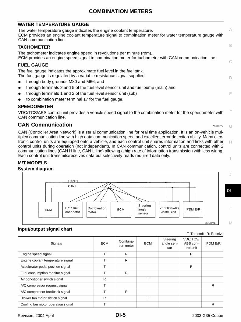
CAN Communication AKS004VM
CAN (Controller Area Network) is a serial communication line for real time application. It is an on-vehicle mul-tiplex communication line with high data communication speed and excellent error detection ability. Many elec-tronic control units are equipped onto a vehicle, and each control unit shares information and links with othercontrol units during operation (not independent). In CAN communication, control units are connected with 2communication lines (CAN H line, CAN L line) allowing a high rate of information transmission with less wiring.Each control unit transmits/receives data but selectively reads required data only.
M/T MODELSSystem diagram
Input/output signal chartT: Transmit R: Receive
SKIA4474E
Signals ECMCombina-tion meter
BCMSteering
angle sen-sor
VDC/TCS/ABS con-trol unit
IPDM E/R
Engine speed signal T R R
Engine coolant temperature signal T R
Accelerator pedal position signal T R
Fuel consumption monitor signal T R
Air conditioner switch signal R T
A/C compressor request signal T R
A/C compressor feedback signal T R
Blower fan motor switch signal R T
Cooling fan motor operation signal T R
DI-6
COMBINATION METERS
Revision; 2004 April 2003 G35 Coupe
Position lights request signal R T R
Low beam request signal T R
Low beam status signal R R T
High beam request signal R T R
High beam status signal R R T
Front fog lights request signal T R
Vehicle speed signalR T
R T R
Sleep request 1 signal R T
Sleep request 2 signal T R
Wake up request 1 signal R T
Wake up request 2 signal R T
Door switch signal (without navigation system) R T R
Door switch signal (with navigation system) T R
Turn indicator signal R T
Seat belt buckle switch signal T R
Oil pressure switch signal R T
Buzzer output signal R T
Trunk switch signal R T
Malfunction indicator lamp signal T R
ASCD SET lamp signal T R
ASCD CRUISE lamp signal T R
Fuel level sensor signal R T
Front wiper request signal T R
Front wiper stop position signal R T
Rear window defogger switch signal T R
Rear window defogger control signal R R T
Hood switch signal R T
Theft warning horn request signal T R
Horn chirp signal T R
Steering angle sensor signal T R
Signals ECMCombina-tion meter
BCMSteering
angle sen-sor
VDC/TCS/ABS con-trol unit
IPDM E/R
COMBINATION METERS
DI-7
C
D
E
F
G
H
I
J
L
M
A
B
DI
Revision; 2004 April 2003 G35 Coupe
A/T MODELSSystem diagram
Input/output signal chartT: Transmit R: Receive
SKIA1880E
Signals ECM TCMCombina-tion meter
BCMSteering
angle sensor
VDC/TCS/ABS con-trol unit
IPDM E/R
Engine speed signal T R R R
Engine coolant temperature signal T R R
Accelerator pedal position signal T R R
Closed throttle position signal T R
Wide open throttle position signal T R
Battery voltage signal T R
Stop lamp switch R T
Fuel consumption monitor signal T R
A/T self-diagnosis signal R T
A/T CHECK indicator lamp signal T R
A/T position indicator signal T R R
ABS operation signal R T
A/T shift schedule change demand signal
R T
Air conditioner switch signal R T
A/C compressor request signal T R
A/C compressor feedback signal T R
Blower fan motor switch signal R T
Cooling fan motor operation signal T R
Position lights request signal R T R
Low beam request signal T R
Low beam status signal R R T
High beam request signal R T R
High beam status signal R R T
Front fog lights request signal T R
Vehicle speed signalR T
R R T R
Sleep request 1 signal R T
Sleep request 2 signal T R
Wake up request 1 signal R T
Wake up request 2 signal R T
DI-8
COMBINATION METERS
Revision; 2004 April 2003 G35 Coupe
Component Parts and Harness Connector Location AKS004VN
Door switch signal (without naviga-tion system)
R T R
Door switch signal (with navigation system)
T R
Turn indicator signal R T
Seat belt buckle switch signal T R
Oil pressure switch signal R T
Buzzer output signal R T
Trunk switch signal R T
Malfunction indicator lamp signal T R
ASCD SET lamp signal T R
ASCD CRUISE lamp signal T R
Fuel level sensor signal R T
Output shaft revolution signal R T
Turbine revolution signal R T
Front wiper request signal T R
Front wiper stop position signal R T
Rear window defogger switch signal T R
Rear window defogger control sig-nal
R R T
Manual mode signal R T
Not manual mode signal R T
Manual mode shift up signal R T
Manual mode shift down signal R T
Manual mode indicator signal T R
Hood switch signal R T
Theft warning horn request signal T R
Horn chirp signal T R
Steering angle sensor signal T R
Signals ECM TCMCombina-tion meter
BCMSteering
angle sensor
VDC/TCS/ABS con-trol unit
IPDM E/R
PKIA2771E
COMBINATION METERS
DI-9
C
D
E
F
G
H
I
J
L
M
A
B
DI
Revision; 2004 April 2003 G35 Coupe
Combination Meter AKS004VO
CHECK
SKIA4118E
DI-10
COMBINATION METERS
Revision; 2004 April 2003 G35 Coupe
Schematic AKS004VP
TKWT0546E
COMBINATION METERS
DI-11
C
D
E
F
G
H
I
J
L
M
A
B
DI
Revision; 2004 April 2003 G35 Coupe
Wiring Diagram — METER — AKS004VQ
TKWT0547E
DI-12
COMBINATION METERS
Revision; 2004 April 2003 G35 Coupe
Terminals and Reference Value for Combination Meter AKS004VR
Termi-nal
Wire Color
Item
Condition
Reference ValueIgnition switch
Operation or condition
17 W/B Fuel level sensor signal — —Refer to DI-22, "FUEL LEVEL SENSOR UNIT CHECK" .
19 W/GVehicle speed signal(2-pulse)
ON
Speedometer operated[When vehicle speed is approx. 40 km/h (25 MPH)]
27 R CAN-L — — —
28 L CAN-H — — —
40 LG Ignition switch (ACC) ACC — Battery voltage
41 G/Y Ignition switch (ON) ON — Battery voltage
42 G/Y Ignition switch (ON) ON — Battery voltage
43 R/W Battery power supply OFF — Battery voltage
45 B Ground ON — Approx. 0V
47 B Ground ON — Approx. 0V
ELF1080D
COMBINATION METERS
DI-13
C
D
E
F
G
H
I
J
L
M
A
B
DI
Revision; 2004 April 2003 G35 Coupe
Meter/Gauges Operation and Odo/Trip Meter AKS004VS
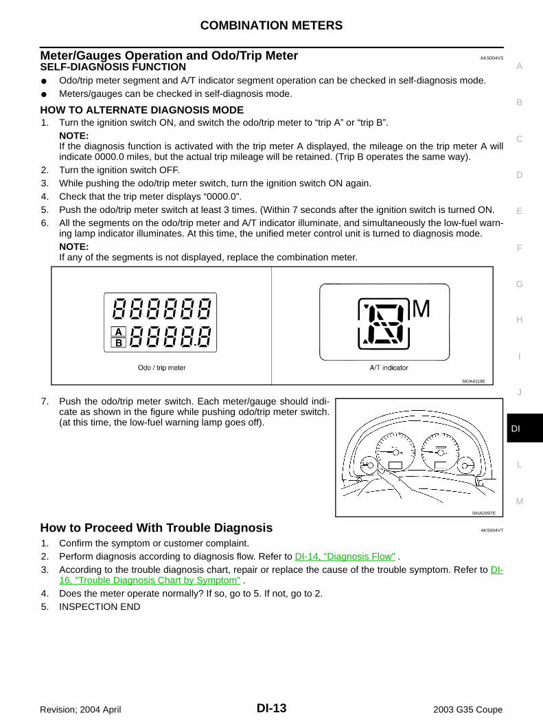
SELF-DIAGNOSIS FUNCTION Odo/trip meter segment and A/T indicator segment operation can be checked in self-diagnosis mode. Meters/gauges can be checked in self-diagnosis mode.
HOW TO ALTERNATE DIAGNOSIS MODE1. Turn the ignition switch ON, and switch the odo/trip meter to “trip A” or “trip B”.
NOTE:If the diagnosis function is activated with the trip meter A displayed, the mileage on the trip meter A willindicate 0000.0 miles, but the actual trip mileage will be retained. (Trip B operates the same way).
2. Turn the ignition switch OFF.3. While pushing the odo/trip meter switch, turn the ignition switch ON again.4. Check that the trip meter displays “0000.0”.5. Push the odo/trip meter switch at least 3 times. (Within 7 seconds after the ignition switch is turned ON.6. All the segments on the odo/trip meter and A/T indicator illuminate, and simultaneously the low-fuel warn-
ing lamp indicator illuminates. At this time, the unified meter control unit is turned to diagnosis mode.NOTE:If any of the segments is not displayed, replace the combination meter.
7. Push the odo/trip meter switch. Each meter/gauge should indi-cate as shown in the figure while pushing odo/trip meter switch.(at this time, the low-fuel warning lamp goes off).
How to Proceed With Trouble Diagnosis AKS004VT
1. Confirm the symptom or customer complaint.2. Perform diagnosis according to diagnosis flow. Refer to DI-14, "Diagnosis Flow" .3. According to the trouble diagnosis chart, repair or replace the cause of the trouble symptom. Refer to DI-
16, "Trouble Diagnosis Chart by Symptom" .4. Does the meter operate normally? If so, go to 5. If not, go to 2.5. INSPECTION END
SKIA4119E
SKIA2097E
DI-14
COMBINATION METERS
Revision; 2004 April 2003 G35 Coupe
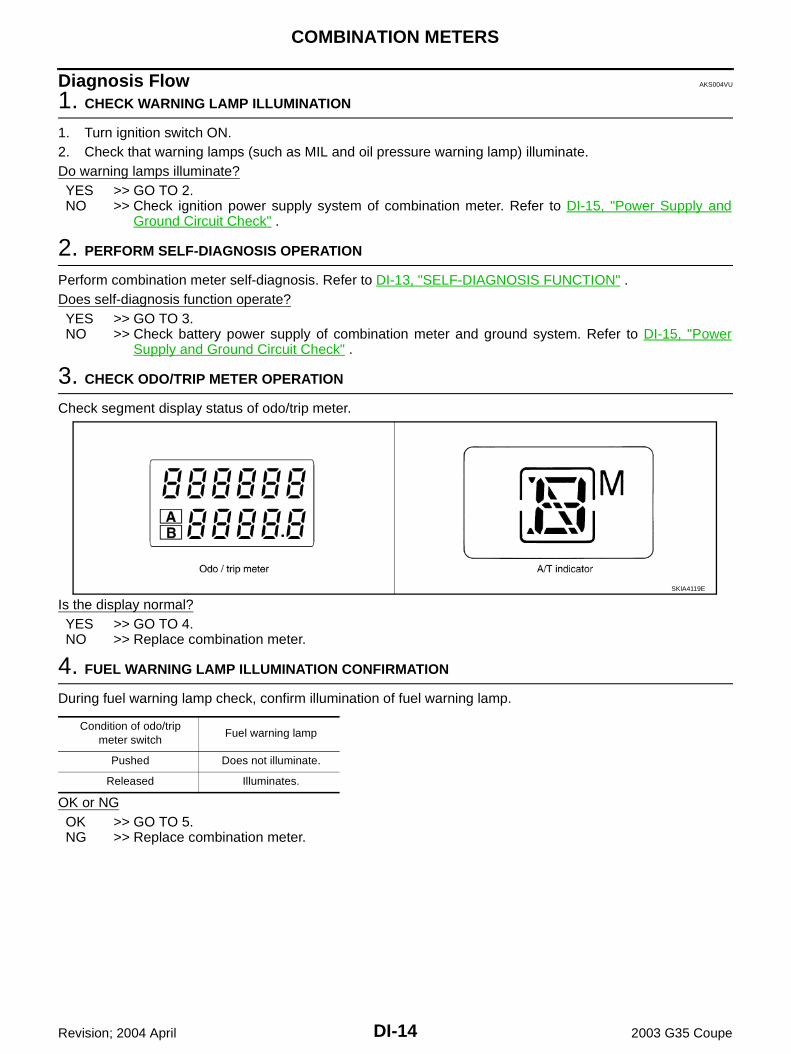
Diagnosis Flow AKS004VU
1. CHECK WARNING LAMP ILLUMINATION
1. Turn ignition switch ON.2. Check that warning lamps (such as MIL and oil pressure warning lamp) illuminate.Do warning lamps illuminate?YES >> GO TO 2.NO >> Check ignition power supply system of combination meter. Refer to DI-15, "Power Supply and
Ground Circuit Check" .
2. PERFORM SELF-DIAGNOSIS OPERATION
Perform combination meter self-diagnosis. Refer to DI-13, "SELF-DIAGNOSIS FUNCTION" .Does self-diagnosis function operate?YES >> GO TO 3.NO >> Check battery power supply of combination meter and ground system. Refer to DI-15, "Power
Supply and Ground Circuit Check" .
3. CHECK ODO/TRIP METER OPERATION
Check segment display status of odo/trip meter.
Is the display normal?YES >> GO TO 4.NO >> Replace combination meter.
4. FUEL WARNING LAMP ILLUMINATION CONFIRMATION
During fuel warning lamp check, confirm illumination of fuel warning lamp.
OK or NGOK >> GO TO 5.NG >> Replace combination meter.
SKIA4119E
Condition of odo/trip meter switch
Fuel warning lamp
Pushed Does not illuminate.
Released Illuminates.
COMBINATION METERS
DI-15
C
D
E
F
G
H
I
J
L
M
A
B
DI
Revision; 2004 April 2003 G35 Coupe
5. CHECK METER CIRCUIT
Check indication of each meter/gauge in self-diagnosis mode.OK or NGYES >> GO TO diagnosis results. Refer to DI-16, "DIAGNOSIS
RESULTS" .NO >> Replace combination meter.
Power Supply and Ground Circuit Check AKS004VV
1. CHECK FUSE
Check for blown combination meter fuses.
OK or NGOK >> GO TO 2.NG >> If fuse is blown, be sure to eliminate cause of problem before installing new fuse. Refer to PG-4,
"POWER SUPPLY ROUTING CIRCUIT" .
2. CHECK POWER SUPPLY CIRCUIT
1. Disconnect combination meter connector.2. Check voltage between combination meter and ground.
OK or NGOK >> GO TO 3.NG >> Check harness for open or short between combination meter and fuse.
SKIA2097E
Unit Power source Fuse No.
Combination meter
Battery 19
Ignition switch (ON) 14
Ignition switch (ACC) 6
Terminals Ignition switch position
(+)
(–) OFF ACC ONConnector
Terminal(Wire color)
M20
40 (LG)
Ground
0VBattery voltage
Battery voltage
41 (G/Y) 0V 0VBattery voltage
42 (G/Y) 0V 0VBattery voltage
43 (R/W)Battery voltage
Battery voltage
Battery voltage
SKIA1905E
DI-16
COMBINATION METERS
Revision; 2004 April 2003 G35 Coupe
3. CHECK GROUND CIRCUIT
Check continuity between combination meter and ground.
OK or NGOK >> INSPECTION ENDNG >> Repair harness or connector.
Trouble Diagnosis Chart by Symptom AKS004VW
DIAGNOSIS RESULTS
Terminals
Continuity(+)
(–)Connector
Terminal(Wire color)
M2045 (B)
Ground Yes47 (B)
SKIA1906E
Trouble phenomenon Possible cause
Tachometer indication is malfunction. Refer to DI-19, "Inspection/Engine Speed Signal" .
Fuel warning lamp indication is irregular. Refer to DI-17, "Inspection/Fuel Level Sensor" .
Fuel gauge indication is malfunction.
Water temperature gauge indication is malfunction. Refer to DI-19, "Inspection/Water Temperature Signal" .
Indication is irregular for the speedometer and odo/trip meter. Refer to DI-19, "Inspection/Vehicle Speed Signal" .
Indications are irregular for more than one gauge. Replace combination meter.
A/T position indicator is malfunction. Refer to DI-42, "A/T Indicator Does Not Illuminate" .
COMBINATION METERS
DI-17
C
D
E
F
G
H
I
J
L
M
A
B
DI
Revision; 2004 April 2003 G35 Coupe
Inspection/Fuel Level Sensor AKS004VX
The following symptoms do not indicate a malfunction.
FUEL GAUGE Depending on vehicle position or driving circumstance, the fuel in the tank flows and the pointer may fluc-
tuate. If the vehicle is fueled with the ignition switch ON, the pointer will move slowly.
LOW-FUEL WARNING LAMPDepending on vehicle position or driving circumstance, the fuel in the tank flows and the warning lamp ON tim-ing may change.
1. CONNECTOR INSPECTION
1. Turn ignition switch OFF.2. Check meter, fuel level sensor unit and terminals (meter-side, unit-side harness-side) for looseness or
bent terminals.OK or NGOK >> GO TO 2.NG >> Repair terminal or connector.
2. CHECK COMBINATION METER CIRCUIT
1. Disconnect combination meter connector and fuel level sensorunit (sub) connector.
2. Check continuity between combination meter harness connectorM19 terminal 17 (W/B) and fuel level sensor unit (sub) harnessconnector B28 terminal 1(W/B).
3. Check continuity between combination meter harness connectorM19 terminal 17 (W/B) and ground.
OK or NGOK >> GO TO 3.NG >> Repair harness or connector.
3. CHECK FUEL LEVEL SENSOR CIRCUIT
1. Disconnect fuel level sensor unit and fuel pump (main) connec-tor.
2. Check continuity between fuel level sensor unit (sub) harnessconnector B28 terminal 2 (Y) and fuel level sensor unit and fuelpump (main) harness connector B27 terminal 2 (Y).
3. Check continuity between fuel level sensor unit (sub) harnessconnector B28 terminal 2 (Y) and ground.
OK or NGOK >> GO TO 4.NG >> Repair harness or connector.
Continuity should exist.
Continuity should not exist.SKIA1930E
Continuity should exist.
Continuity should not exist.SKIA1931E
DI-18
COMBINATION METERS
Revision; 2004 April 2003 G35 Coupe
4. CHECK GROUND CIRCUIT
Check continuity between fuel level sensor unit and fuel pump(main) harness connector B27 terminal 5 (B) and ground.
OK or NGOK >> GO TO 5.NG >> Repair harness or connector.
5. CHECK FUEL LEVEL SENSOR
Check fuel level sensor units. Refer to DI-22, "FUEL LEVEL SENSOR UNIT CHECK" .OK or NGOK >> GO TO 6.NG >> Replace fuel level sensor unit and fuel pump (main) or fuel level sensor unit (sub).
6. CHECK INSTALLATION CONDITION
Check fuel level sensor unit installation, and check whether the float arm interferes or binds with any of theinternal components in the fuel tank.OK or NGOK >> Replace combination meter.NG >> Install fuel level sensor unit properly.
Continuity should exist.
SKIA1932E
COMBINATION METERS
DI-19
C
D
E
F
G
H
I
J
L
M
A
B
DI
Revision; 2004 April 2003 G35 Coupe
Inspection/Engine Speed Signal AKS004VY
1. CHECK ECM SELF-DIAGNOSIS
Perform ECM self-diagnosis. Refer to EC-51, "Emission-Related Diagnostic Information" .OK or NGOK >> Replace combination meter.NG >> Perform “Diagnostic Procedure” in displayed DTC.
Inspection/Water Temperature Signal AKS004VZ
1. CHECK ECM SELF-DIAGNOSIS
Preform the ECM self-diagnosis. Refer to EC-51, "Emission-Related Diagnostic Information" . OK or NGOK >> Replace combination meter.NG >> Perform “Diagnostic Procedure” in displayed DTC.
Inspection/Vehicle Speed Signal AKS004W0
1. CHECK VDC/TCS/ABS CONTROL UNIT SELF-DIAGNOSIS
Preform VDC/TCS/ABS control unit self-diagnosis. Refer to BRC-29, "CONSULT-II Functions" .OK or NGOK >> Replace combination meter.NG >> Perform “Diagnostic Procedure” in displayed self-diagnosis results.
DI-20
COMBINATION METERS
Revision; 2004 April 2003 G35 Coupe
The Fuel Gauge Pointer Fluctuates, Indicator Wrong Value or Varies AKS004W1
1. CHECK FUEL GAUGE FLUCTUATION
Test drive vehicle to see if gauge fluctuates only during driving or before or after stopping.Does the indication value vary only during driving or before or after stopping?YES >> The pointer fluctuation may be caused by fuel level change in the fuel tank. Condition is normal.NO >> Ask the customer about the situation when the symptom occurs in detail, and perform the trouble
diagnosis.
The Fuel Gauge Does Not Move to FULL Position AKS004W2
1. QUESTION 1
Does it take a long time for the pointer to move to FULL position?YES or NOYES >> GO TO 2.NO >> GO TO 3.
2. QUESTION 2
Was the vehicle fueled with the ignition switch ON?YES or NOYES >> Be sure to fuel the vehicle with the ignition switch OFF. Otherwise, it will take a long time to move
to FULL position because of the characteristic of the fuel gauge.NO >> GO TO 3.
3. QUESTION 3
Is the vehicle parked on an incline?YES or NOYES >> Check fuel level indication with vehicle on a level surface.NO >> GO TO 4.
4. QUESTION 4
During driving, does the fuel gauge pointer move gradually toward EMPTY position?YES or NOYES >> Check fuel level sensor unit. Refer to DI-22, "FUEL LEVEL SENSOR UNIT CHECK" .NO >> The float arm may interfere or bind with any of the components in the fuel tank.
COMBINATION METERS
DI-21
C
D
E
F
G
H
I
J
L
M
A
B
DI
Revision; 2004 April 2003 G35 Coupe
The Fuel Gauge Does Not Work AKS004W3
1. CHECK HARNESS CONNECTOR
1. Turn ignition switch OFF.2. Check combination meter, fuel level sensor unit, and terminals (meter-side, unit side and harness-side) for
poor connection and bend.OK or NGOK >> GO TO 2.NG >> Repair terminal or connector.
2. CHECK INSTALLATION CONDITION
Check fuel level sensor unit installation (refer to FL-5, "FUEL LEVEL SENSOR UNIT, FUEL FILTER ANDFUEL PUMP ASSEMBLY" , and check whether the float arm interferes or binds with any components insidethe fuel tank.OK or NGOK >> Fuel level sensor unit is OK.NG >> Check fuel level sensor. Refer to DI-17, "Inspection/Fuel Level Sensor" .
Low Fuel Warning Lamp Illuminates at All Times or Does Not Illuminate AKS004W4
1. CHECK SELF-DIAGNOSIS
Perform combination meter self-diagnosis. Refer toDI-13, "Meter/Gauges Operation and Odo/Trip Meter" .OK or NGOK >> Check fuel level sensor unit. Refer to DI-22, "FUEL LEVEL SENSOR UNIT CHECK" .NG >> Replace combination meter.
DI-22
COMBINATION METERS
Revision; 2004 April 2003 G35 Coupe
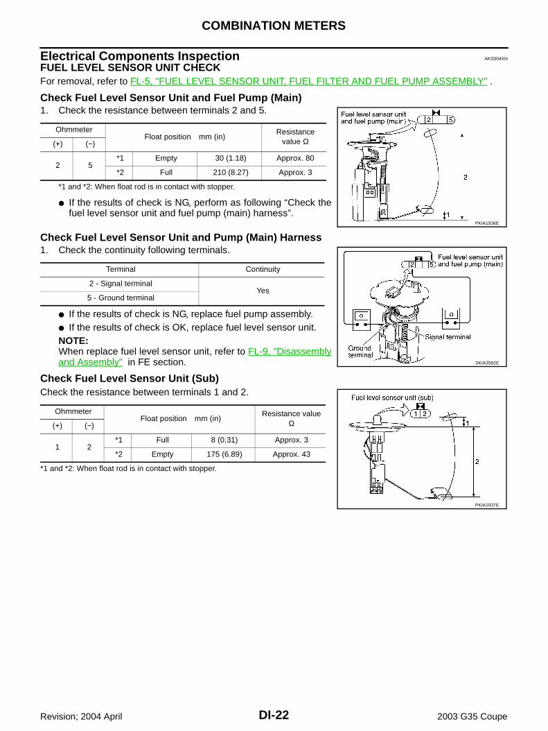
Electrical Components Inspection AKS004XN
FUEL LEVEL SENSOR UNIT CHECKFor removal, refer to FL-5, "FUEL LEVEL SENSOR UNIT, FUEL FILTER AND FUEL PUMP ASSEMBLY" .
Check Fuel Level Sensor Unit and Fuel Pump (Main) 1. Check the resistance between terminals 2 and 5.
*1 and *2: When float rod is in contact with stopper.
If the results of check is NG, perform as following “Check thefuel level sensor unit and fuel pump (main) harness”.
Check Fuel Level Sensor Unit and Pump (Main) Harness1. Check the continuity following terminals.
If the results of check is NG, replace fuel pump assembly. If the results of check is OK, replace fuel level sensor unit.NOTE:When replace fuel level sensor unit, refer to FL-9, "Disassemblyand Assembly" in FE section.
Check Fuel Level Sensor Unit (Sub)Check the resistance between terminals 1 and 2.
*1 and *2: When float rod is in contact with stopper.
OhmmeterFloat position mm (in)
Resistance value Ω(+) (−)
2 5*1 Empty 30 (1.18) Approx. 80
*2 Full 210 (8.27) Approx. 3
PKIA1936E
Terminal Continuity
2 - Signal terminalYes
5 - Ground terminal
SKIA3582E
OhmmeterFloat position mm (in)
Resistance value Ω(+) (−)
1 2*1 Full 8 (0.31) Approx. 3
*2 Empty 175 (6.89) Approx. 43
PKIA1937E
COMBINATION METERS
DI-23
C
D
E
F
G
H
I
J
L
M
A
B
DI
Revision; 2004 April 2003 G35 Coupe
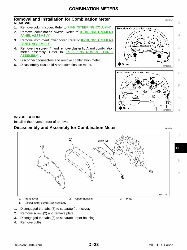
Removal and Installation for Combination Meter AKS004W6
REMOVAL1. Remove column cover. Refer to PS-9, "STEERING COLUMN" .2. Remove combination switch. Refer to IP-10, "INSTRUMENT
PANEL ASSEMBLY" .4. Remove the screw (4) and remove cluster lid A and combination
meter assembly. Refer to IP-10, "INSTRUMENT PANELASSEMBLY" .
5. Disconnect connectors and remove combination meter.6. Disassembly cluster lid A and combination meter.
INSTALLATIONInstall in the reverse order of removal.
Disassembly and Assembly for Combination Meter AKS004W7
1. Disengaged the tabs (8) to separate front cover.2. Remove screw (2) and remove plate.3. Disengaged the tabs (8) to separate upper housing.4. Remove bulbs.
SKIA1083E
SKIA1084E
1. Front cover 2. Upper housing 3. Plate
4. Unified meter control unit assembly
SKIA1443E
DI-24
COMPASS
Revision; 2004 April 2003 G35 Coupe
COMPASS PFP:24835
System Description AKS004W8
This unit displays earth magnetism and heading direction of vehicle.
DIRECTION DISPLAYPush the switch when the ignition key is in the “ON” or “START” position. The direction will be displayed.
SKIA1945E
COMPASS
DI-25
C
D
E
F
G
H
I
J
L
M
A
B
DI
Revision; 2004 April 2003 G35 Coupe
Wiring Diagram — COMPASS — AKS004W9
TKWT0548E
DI-26
COMPASS
Revision; 2004 April 2003 G35 Coupe
Power Supply and Ground Circuit Check for Compass AKS004WA
1. CHECK FUSE
Check 10A fuse [No. 12, located in fuse block (J/B)].OK or NGOK >> GO TO 2.NG >> If fuse is blown, be sure to eliminate case of problem before installing new fuse. Refer to PG-4,
"POWER SUPPLY ROUTING CIRCUIT" .
2. CHECK POWER SUPPLY CIRCUIT
1. Disconnect compass connector. 2. Check voltage between compass harness connector M81 termi-
nal 4 (Y/G) and ground.
OK or NGOK >> GO TO 3.NG >> Check harness for open or short between compass and
fuse.
3. CHECK GROUND CIRCUIT
Check continuity between compass harness connector M81 terminal1 (B) and ground.
OK or NGOK >> INSPECTION ENDNG >> Repair or replace harness for ground circuit.
Battery voltage should exist.
SKIA4120E
Continuity should exist.
SKIA4121E
COMPASS
DI-27
C
D
E
F
G
H
I
J
L
M
A
B
DI
Revision; 2004 April 2003 G35 Coupe
Fail-Safe System AKS004WB
DESCRIPTION If there is no response from display and A/C auto amp., previous display is kept for 10 minutes. After 10
minutes, “---” is displayed. (Only when there is no response continuously for 10 minutes.) If display and A/C auto amp. receives normal data within 10 minutes, normal operation will be recovered. If display and A/C auto amp. receives normal data while “---” is being displayed, normal operation will be
recovered. If ignition switch is turned OFF within 10 minutes: Previously retained data is displayed when ignition
switch is turned ON again. Then after 10 minutes, “---” is displayed. If response is never received after battery is turned ON, no data is retained. Therefore nothing is dis-
played for 10 minutes.
Compass Does not Display AKS004WC
1. DISPLAY AND A/C AUTO AMP. SELF-DIAGNOSIS CHECK
Check display and A/C auto amp. self-diagnosis. Refer to ATC-57, "FUNCTION CONFIRMATION PROCE-DURE" .Does display and A/C auto amp. segments all displayed?YES >> Check fail safe system. refer to DI-27, "Fail-Safe System" .NO >> Replace the display and A/C auto amp.
Compass Display “– – –” AKS004WD
1. FAIL-SAFE MODE CHECK
Check that fail-safe mode is not activated. Refer to DI-27, "Fail-Safe System" .Does be activated fail-safe mode?YES >> GO TO 3.NO >> GO TO 2.
2. DISPLAY AND A/C AUTO AMP. SELF-DIAGNOSIS CHECK
Perform display and A/C auto amp. self-diagnosis. Refer to ATC-57, "FUNCTION CONFIRMATION PROCE-DURE" .Does display and A/C auto amp. segments all displayed?YES >> INSPECTION ENDNO >> Replace the display and A/C auto amp.
3. POWER AND GROUND CIRCUIT CHECK
Check power and ground circuit. Refer to DI-26, "Power Supply and Ground Circuit Check for Compass" .OK or NGOK >> GO TO 4.NG >> Repair power and ground circuit.
DI-28
COMPASS
Revision; 2004 April 2003 G35 Coupe
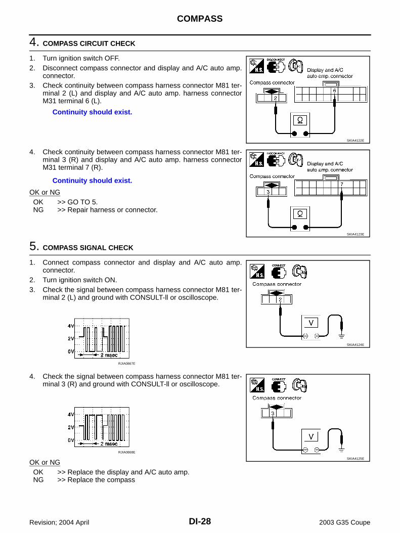
4. COMPASS CIRCUIT CHECK
1. Turn ignition switch OFF.2. Disconnect compass connector and display and A/C auto amp.
connector.3. Check continuity between compass harness connector M81 ter-
minal 2 (L) and display and A/C auto amp. harness connectorM31 terminal 6 (L).
4. Check continuity between compass harness connector M81 ter-minal 3 (R) and display and A/C auto amp. harness connectorM31 terminal 7 (R).
OK or NGOK >> GO TO 5.NG >> Repair harness or connector.
5. COMPASS SIGNAL CHECK
1. Connect compass connector and display and A/C auto amp.connector.
2. Turn ignition switch ON.3. Check the signal between compass harness connector M81 ter-
minal 2 (L) and ground with CONSULT-ll or oscilloscope.
4. Check the signal between compass harness connector M81 ter-minal 3 (R) and ground with CONSULT-ll or oscilloscope.
OK or NGOK >> Replace the display and A/C auto amp.NG >> Replace the compass
Continuity should exist.
SKIA4122E
Continuity should exist.
SKIA4123E
SKIA4124E
RJIA0867E
SKIA4125E
RJIA0868E
COMPASS
DI-29
C
D
E
F
G
H
I
J
L
M
A
B
DI
Revision; 2004 April 2003 G35 Coupe
Forward Direction Indication Slips Off The Mark Or Incorrect AKS004WE
1. ZONE VARIATION CHANGE IS NOT DONE
Perform the zone variation change.OK or NGOK >> INSPECTION ENDNG >> Replace the compass.
Compass Reading Remains Unchanged AKS004WF
1. POWER AND GROUND CIRCUIT CHECK
Check power and ground circuit. Refer to DI-26, "Power Supply and Ground Circuit Check for Compass" .OK or NGOK >> Replace the compass.NG >> Repair power and ground circuit.
DI-30
COMPASS
Revision; 2004 April 2003 G35 Coupe
Calibration Procedure for Compass AKS004WG
The difference between magnetic North and geographical North can sometimes be great enough to causefalse compass readings.In order for the compass to operate accurately in a particular zone, it must be calibrated using the followingprocedure.
CORRECTION FUNCTIONS OF COMPASSIf the direction is not shown correctly, carry out initial correction.
INITIAL CORRECTION PROCEDURE FOR COMPASS1. Pushing the “COMP” switch for about 10 seconds will enter the
initial correction mode. The direction bar starts blinking.2. Turn off all electrical equipment (turn signals, hazard signal, A/
C, lights, etc.). In a broad, flat, and safe location, drive the vehi-cle slowly [approximately 5 km/h (3 MPH) or less], and turn thevehicle 360° or more several times. When the direction appearson the display, correction is complete.
NOTE:The correct direction may not be shown in locations where the earth's magnetic field is disrupted, such as those listed below. Elevated bridges Railroad crossings Streets lined with large buildings Iron bridges Tunnels Locations above subways Underground parking areas Near large vehicles Electric power substations
SKIA2076E
SKIA1946E
COMPASS
DI-31
C
D
E
F
G
H
I
J
L
M
A
B
DI
Revision; 2004 April 2003 G35 Coupe
If display correction is performed in any of the above locations, accurate correction may not be possible. When heater or A/C fan speed is at maximum, the direction indicator display may move. This is not a mal-
function. It will return to normal when the heater or A/C fan speed is reduced.
Removal and Installation of Compass AKS004WH
REMOVAL1. Remove instrument panel and pad. Refer to IP-11, "Removal and Installation" .2. Remove screw (1), and remove compass.
INSTALLATIONInstall in the reverse order of removal.
PKIA2379E
DI-32
WARNING LAMPS
Revision; 2004 April 2003 G35 Coupe
WARNING LAMPS PFP:24814
Schematic AKS004WI
TKWT0549E
WARNING LAMPS
DI-33
C
D
E
F
G
H
I
J
L
M
A
B
DI
Revision; 2004 April 2003 G35 Coupe
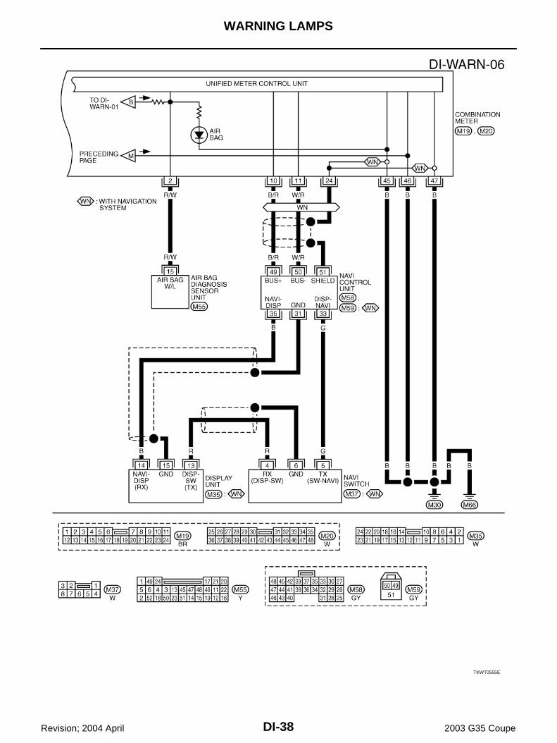
Wiring Diagram — WARN — AKS004WJ
TKWT0550E
DI-34
WARNING LAMPS
Revision; 2004 April 2003 G35 Coupe
TKWT0551E
WARNING LAMPS
DI-35
C
D
E
F
G
H
I
J
L
M
A
B
DI
Revision; 2004 April 2003 G35 Coupe
TKWT0552E
DI-36
WARNING LAMPS
Revision; 2004 April 2003 G35 Coupe
TKWT0553E
WARNING LAMPS
DI-37
C
D
E
F
G
H
I
J
L
M
A
B
DI
Revision; 2004 April 2003 G35 Coupe
TKWT0554E
DI-38
WARNING LAMPS
Revision; 2004 April 2003 G35 Coupe
TKWT0555E
WARNING LAMPS
DI-39
C
D
E
F
G
H
I
J
L
M
A
B
DI
Revision; 2004 April 2003 G35 Coupe
Oil Pressure Warning Lamp Stays Off (Ignition Switch ON) AKS004WK
1. CHECK BETWEEN IPDM E/R AND COMBINATION METER
Activate IPDM E/R auto active test. Refer to PG-22, "Auto Active Test" .Does auto active test activate?YES >> Replace combination meter.NO >> GO TO 2.
1. Disconnect IPDM E/R connector and oil pressure switch con-nector.
2. Check continuity between IPDM E/R harness connector E9 ter-minal 50 (Y/B) and ground.
OK or NGOK >> GO TO 2.NG >> Repair harness or connector.
2. CHECK IPDM E/R OUTPUT SIGNAL
1. Connect IPDM E/R connector.2. Turn ignition switch ON.3. Check voltage between IPDM E/R harness connector E9 termi-
nal 50 (Y/B) and ground.
OK or NGOK >> Check oil pressure switch. Refer to DI-40, "OIL PRES-
SURE SWITCH" .NG >> Replace IPDM E/R.
Component Inspection AKS004WM
OIL PRESSURE SWITCHCheck continuity between the oil pressure switch and body ground.
Continuity should not exist.
SKIA2145E
Battery voltage should exist.
SKIA2144E
Condition Oil pressure kPa (kg/cm2 , psi)
Continuity
Engine stopped Less than 29 (0.3, 4) Yes
Engine running More than 29 (0.3, 4) No
ELF0044D
A/T INDICATOR
DI-41
C
D
E
F
G
H
I
J
L
M
A
B
DI
Revision; 2004 April 2003 G35 Coupe
A/T INDICATOR PFP:24814
Wiring Diagram — AT/IND — AKS004WN
TKWT0556E
DI-42
A/T INDICATOR
Revision; 2004 April 2003 G35 Coupe
A/T Indicator Does Not Illuminate AKS004WO
1. CHECK COMBINATION METER SELF-DIAGNOSIS
Perform combination meter self-diagnosis. Refer to DI-13, "Meter/Gauges Operation and Odo/Trip Meter" .
YES or NOYES >> GO TO 2.NO >> Replace combination meter.
2. CHECK TCM SELF-DIAGNOSIS
Perform TCM self-diagnosis. Refer to AT-41, "TROUBLE DIAGNOSIS" .OK or NGOK >> Replace combination meter.NG >> Go to TCM trouble diagnosis.
Does all segments displayed?
WARNING CHIME
DI-43
C
D
E
F
G
H
I
J
L
M
A
B
DI
Revision; 2004 April 2003 G35 Coupe
WARNING CHIME PFP:24814
Component Parts and Harness Connector Location AKS004WP
System Description AKS004WQ
The warning chime is controlled by the BCM.The warning chime is located in the combination meter.Combination meter is received buzzer signal from BCM with CAN communication line, the warning chime willsound.
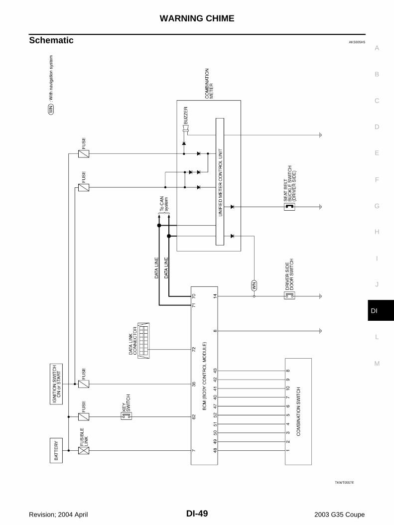
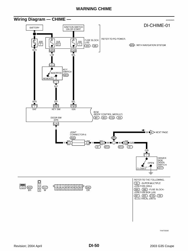
FUNCTIONPower is supplied at all times through 50A fuse (letter F , located in the fuse and fusible link box) to BCM terminal 7, through 10A fuse [No. 21, located in the fuse block (J/B)] to key switch terminal 2 and through 10A fuse [No. 19, located in the fuse block (J/B)] to combination meter terminal 43.When ignition switch ON or START position, power is supplied through 10A fuse [No. 1, located in the fuse block (J/B)] to BCM terminal 35, through 10A fuse [No. 14, located in the fuse block (J/B)] to combination meter terminal 41 and 42.Ground is supplied to BCM terminal 8 through body grounds E17 and E43 and to combination meter terminals 45 through body grounds M30 and M66.
SKIA2118E
DI-44
WARNING CHIME
Revision; 2004 April 2003 G35 Coupe
IGNITION KEY WARNING CHIMEWith the key inserted into the ignition switch, and the driver's door open, the warning chime will sound.Poweris supplied through key switch terminal 1 to BCM terminal 62, andGround is supplied (with navigation system) to combination meter terminal 7 through driver side door switch terminal 1. Driver side door switch is case grounded.Combination meter send door open signal to BCM with CAN communication system. Ground is supplied (without navigation system) to BCM terminal 14 through driver side door switch terminal 1. Driver side door switch is case grounded.BCM detects key inserted into the ignition switch, and sends buzzer output signal (key warning signal) to com-bination meter with CAN communication line.When combination meter receives buzzer output signal (key warning signal), it sounds warning chime.
LIGHT WARNING CHIMEWith the key removed from the ignition switch, the driver's door open, and the lighting switch in 1ST or 2NDposition, the warning chime will sound. [Except when headlamp battery saver control operates (for 5 minutesafter ignition switch is turned to OFF or ACC position) and headlamps do not illuminate.]Signal is supplied from combination switch (lighting switch) terminals 1, 2, 3, 4, 5, 6, 7, 8, 9 and 10 to BCM terminals 40, 41, 42, 43, 47, 48, 49, 50, 51 and 52.
NOTE:BCM detected lighting switch in 1st or 2nd position, refer to LT-122, "Combination Switch Reading Func-tion" .
Ground is supplied (with navigation system) to combination meter terminal 7 through driver side door switch terminal 1. Driver side door switch is case grounded.Combination meter send door open signal to BCM with CAN communication system. Ground is supplied (without navigation system) from driver side door switch terminal 1 to BCM terminal 14.BCM detects headlamps are illuminated, and sends buzzer output signal (light warning signal) to combinationmeter with CAN communication line.When combination meter receives buzzer output signal (light warning signal), it sounds warning chime.
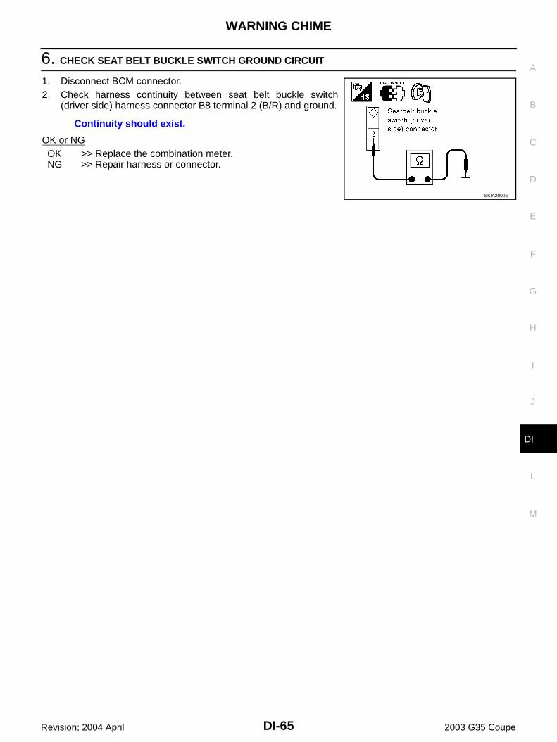
SEAT BELT WARNING CHIMEWith ignition switch turned ON and seat belt unfastened [seat belt buckle switch (driver side) ON], warningchime will sound for approximately 6 seconds.Ground is supplied from seat belt buckle switch (driver side) terminal 1 to combination meter terminal 1.Seat belt buckle switch (driver side) terminal 2 is grounded through body grounds B5 and B29.BCM receives seat belt buckle switch signal (seat belt unfastened) from combination meter over CAN commu-nication line, and then BCM sends buzzer output signal (seat belt warning signal) to combination meter withCAN communication line.When combination meter receives buzzer output signal (seat belt warning signal), it sounds warning chime.
WARNING CHIME
DI-45
C
D
E
F
G
H
I
J
L
M
A
B
DI
Revision; 2004 April 2003 G35 Coupe
CAN Communication AKS005QJ
CAN (Controller Area Network) is a serial communication line for real time application. It is an on-vehicle mul-tiplex communication line with high data communication speed and excellent error detection ability. Many elec-tronic control units are equipped onto a vehicle, and each control unit shares information and links with othercontrol units during operation (not independent). In CAN communication, control units are connected with 2communication lines (CAN H line, CAN L line) allowing a high rate of information transmission with less wiring.Each control unit transmits/receives data but selectively reads required data only.
M/T MODELSSystem diagram
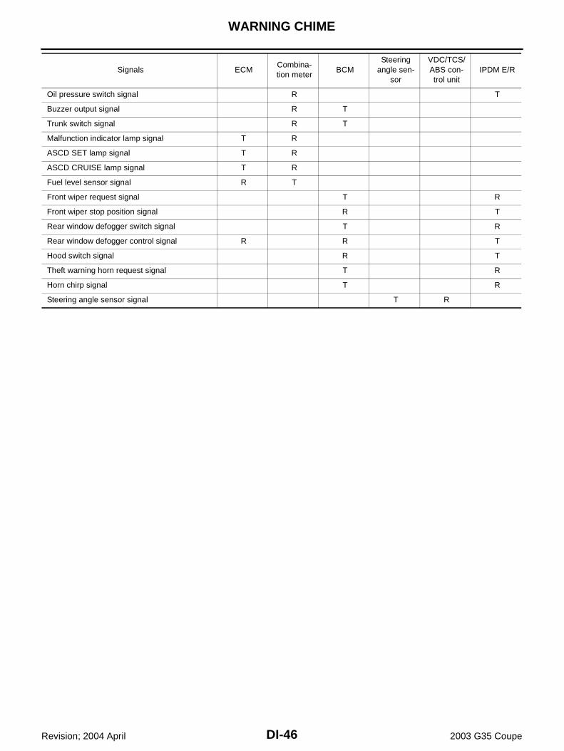
Input/output signal chartT: Transmit R: Receive
SKIA4474E
Signals ECMCombina-tion meter
BCMSteering
angle sen-sor
VDC/TCS/ABS con-trol unit
IPDM E/R
Engine speed signal T R R
Engine coolant temperature signal T R
Accelerator pedal position signal T R
Fuel consumption monitor signal T R
Air conditioner switch signal R T
A/C compressor request signal T R
A/C compressor feedback signal T R
Blower fan motor switch signal R T
Cooling fan motor operation signal T R
Position lights request signal R T R
Low beam request signal T R
Low beam status signal R R T
High beam request signal R T R
High beam status signal R R T
Front fog lights request signal T R
Vehicle speed signalR T
R T R
Sleep request 1 signal R T
Sleep request 2 signal T R
Wake up request 1 signal R T
Wake up request 2 signal R T
Door switch signal (without navigation system) R T R
Door switch signal (with navigation system) T R
Turn indicator signal R T
Seat belt buckle switch signal T R
DI-46
WARNING CHIME
Revision; 2004 April 2003 G35 Coupe
Oil pressure switch signal R T
Buzzer output signal R T
Trunk switch signal R T
Malfunction indicator lamp signal T R
ASCD SET lamp signal T R
ASCD CRUISE lamp signal T R
Fuel level sensor signal R T
Front wiper request signal T R
Front wiper stop position signal R T
Rear window defogger switch signal T R
Rear window defogger control signal R R T
Hood switch signal R T
Theft warning horn request signal T R
Horn chirp signal T R
Steering angle sensor signal T R
Signals ECMCombina-tion meter
BCMSteering
angle sen-sor
VDC/TCS/ABS con-trol unit
IPDM E/R
WARNING CHIME
DI-47
C
D
E
F
G
H
I
J
L
M
A
B
DI
Revision; 2004 April 2003 G35 Coupe
A/T MODELSSystem diagram
Input/output signal chartT: Transmit R: Receive
SKIA1880E
Signals ECM TCMCombina-tion meter
BCMSteering
angle sensor
VDC/TCS/ABS con-trol unit
IPDM E/R
Engine speed signal T R R R
Engine coolant temperature signal T R R
Accelerator pedal position signal T R R
Closed throttle position signal T R
Wide open throttle position signal T R
Battery voltage signal T R
Stop lamp switch R T
Fuel consumption monitor signal T R
A/T self-diagnosis signal R T
A/T CHECK indicator lamp signal T R
A/T position indicator signal T R R
ABS operation signal R T
A/T shift schedule change demand signal
R T
Air conditioner switch signal R T
A/C compressor request signal T R
A/C compressor feedback signal T R
Blower fan motor switch signal R T
Cooling fan motor operation signal T R
Position lights request signal R T R
Low beam request signal T R
Low beam status signal R R T
High beam request signal R T R
High beam status signal R R T
Front fog lights request signal T R
Vehicle speed signalR T
R R T R
Sleep request 1 signal R T
Sleep request 2 signal T R
Wake up request 1 signal R T
Wake up request 2 signal R T
DI-48
WARNING CHIME
Revision; 2004 April 2003 G35 Coupe
Door switch signal (without naviga-tion system)
R T R
Door switch signal (with navigation system)
T R
Turn indicator signal R T
Seat belt buckle switch signal T R
Oil pressure switch signal R T
Buzzer output signal R T
Trunk switch signal R T
Malfunction indicator lamp signal T R
ASCD SET lamp signal T R
ASCD CRUISE lamp signal T R
Fuel level sensor signal R T
Output shaft revolution signal R T
Turbine revolution signal R T
Front wiper request signal T R
Front wiper stop position signal R T
Rear window defogger switch signal T R
Rear window defogger control sig-nal
R R T
Manual mode signal R T
Not manual mode signal R T
Manual mode shift up signal R T
Manual mode shift down signal R T
Manual mode indicator signal T R
Hood switch signal R T
Theft warning horn request signal T R
Horn chirp signal T R
Steering angle sensor signal T R
Signals ECM TCMCombina-tion meter
BCMSteering
angle sensor
VDC/TCS/ABS con-trol unit
IPDM E/R
WARNING CHIME
DI-49
C
D
E
F
G
H
I
J
L
M
A
B
DI
Revision; 2004 April 2003 G35 Coupe
Schematic AKS005H5
TKWT0557E
DI-50
WARNING CHIME
Revision; 2004 April 2003 G35 Coupe
Wiring Diagram — CHIME — AKS004WS
TKWT0558E
WARNING CHIME
DI-51
C
D
E
F
G
H
I
J
L
M
A
B
DI
Revision; 2004 April 2003 G35 Coupe
TKWT0559E
DI-52
WARNING CHIME
Revision; 2004 April 2003 G35 Coupe
TKWT0560E
WARNING CHIME
DI-53
C
D
E
F
G
H
I
J
L
M
A
B
DI
Revision; 2004 April 2003 G35 Coupe
Terminals and Reference Value for BCM AKS004WT
How to Proceed With Trouble Diagnosis AKS004WU
1. Confirm the symptom or customer complaint.2. Understand operation description and function description. Refer to DI-43, "System Description" .3. Perform the preliminary check. Refer to DI-54, "Preliminary Check" .4. Check symptom and repair or replace the cause of malfunction.5. Does the warning chime operate normally? If so, go to 6. If not, go to 4.6. INSPECTION END
Terminal No.
Wire color
Item
Condition
Reference valueIgnition switch
Measurement method
7 W/R Battery power supply OFF — Battery voltage
8 B Ground ON — Approx. 0V
14 Y Driver side door switch signal OFF Driver's doorON (open) Approx. 0V
OFF (closed) Approx. 5V
35 W/L Ignition switch (ON) ON — Battery voltage
40 Y/R Combination switch output 2
ON —
41 PU Combination switch output 3
42 L Combination switch output 4
43 GY Combination switch output 5
47 Y Combination switch output 1
48 W/R Combination switch input 1
ONLighting switch and wiper switch are OFF.
4.5 or more
49 W/G Combination switch input 2
50 W/L Combination switch input 3
51 G Combination switch input 4
52 G/R Combination switch input 5
62 B/P Key switch signal OFFKey is removed Approx. 0V
Key is inserted Battery voltage
70 L CAN H OFF — —
71 R CAN L OFF — —
SKIA1119J
DI-54
WARNING CHIME
Revision; 2004 April 2003 G35 Coupe
Preliminary Check AKS004WV
INSPECTION FOR POWER SUPPLY AND GROUND CIRCUIT
1. CHECK FUSE
Check for blown BCM fuses.
Refer to DI-50, "Wiring Diagram — CHIME —" .
OK or NGOK >> GO TO 2.NG >> If fuse is blown, be sure to eliminate cause of problem before installing new fuse. Refer to PG-4,
"POWER SUPPLY ROUTING CIRCUIT" .
2. CHECK POWER SUPPLY CIRCUIT
1. Disconnect BCM connector.2. Check voltage between BCM connector and ground.
OK or NGOK >> GO TO 3.NG >> Check harness for open or short between BCM and fuse.
3. CHECK GROUND CIRCUIT
1. Turn ignition switch OFF.2. Check continuity between BCM and ground.
OK or NGOK >> INSPECTION ENDNG >> Repair harness or connector.
Unit Power source Fuse No.
BCMBattery F
Ignition switch (ON) 1
Terminals Ignition switch position
(+)
(–) OFF ACC ONConnector
Terminal (Wire color)
E105 7 (W/R)
Ground
Battery voltage
Battery voltage
Battery voltage
M1 35 (W/L) 0V 0VBattery voltage
SKIA2002E
Terminals
Continuity(+)
(–)Connector
Terminal (Wire color)
E105 8 (B) Ground Yes
PKIA0560E
WARNING CHIME
DI-55
C
D
E
F
G
H
I
J
L
M
A
B
DI
Revision; 2004 April 2003 G35 Coupe
CONSULT-II Function AKS004WW
CONSULT-II executes the following functions by combining data reception and command transmission viathe communication line from BCM. Work support, self-diagnosis, data monitor, and active test display.
DIAGNOSTIC ITEMS DESCRIPTION
CONSULT-II BASIC OPERATION PROCEDURE1. With the ignition switch OFF, connect “CONSULT-II” and “CON-
SULT-II CONVERTER” to the data link connector, and turn theignition switch ON.
2. Touch “START (NISSAN BASED VHCL)”.
3. Touch “BCM” on “SELECT SYSTEM” screen.If “BCM” is not indicated, go to GI-39, "CONSULT-II Data LinkConnector (DLC) Circuit" .
BCM diagnosis position Diagnosis mode Description
KEY WARN ALMData monitor The input data to the BCM control unit is displayed in real time.
Active test Operation of electrical loads can be checked by sending driving signal to them.
LIGHT WARN ALMData monitor The input data to the BCM control unit is displayed in real time.
Active test Operation of electrical loads can be checked by sending driving signal to them.
SEAT BELT ALMData monitor The input data to the BCM control unit is displayed in real time.
Active test Operation of electrical loads can be checked by sending driving signal to them.
BCM Self-diagnostic BCM performs self-diagnosis of CAN communication and combination switch.
5. Select “DATA MONITOR” “ACTIVE TEST” or “SELF-DIAGRESULTS”.
DATA MONITOROperation Procedure1. Touch “KEY WARN ALM”, “LIGHT WARN ALM” or “SEAT BELT ALM” on “SELECT TEST ITEM” screen.2. Touch “DATA MONITOR” on “SELECT DIAG MODE” screen.3. Touch “ALL SIGNALS” or “SELECTION FROM MENU” on “DATA MONITOR″ screen.
4. Touch “START”.5. If “SELECTION FROM MENU” is selected, touch the desired monitor item. If “ALL SIGNALS” is selected,
all items required to control are monitored.6. During monitoring, touching “RECORD” can start recording the monitored item status.
Data Monitor Item (Key Warning Chime)
Data Monitor Item (Light Warning Chime)
Data Monitor Item (Seat Belt Warning Chime)
LKIA0072E
ALL SIGNALS Monitors the main items.
SELECTION FROM MENU Selects and monitors the items.
Monitored item Description
IGN ON SW Indicates [ON/OFF] condition of ignition switch.
KEY ON SW Indicates [ON/OFF] condition of key switch.
DOOR SW-DR Indicates [ON/OFF] condition of driver side door switch.
Monitored item Description
IGN ON SW Indicates [ON/OFF] condition of ignition switch.
DOOR SW-DR Indicates [ON/OFF] condition of driver side door switch.
TAIL LAMP SW Indicates [ON/OFF] condition of lighting switch.
Monitored item Description
IGN ON SW Indicates [ON/OFF] condition of ignition switch.
SEAT BELT SW Indicates [ON/OFF] condition of seat belt buckle switch.
WARNING CHIME
DI-57
C
D
E
F
G
H
I
J
L
M
A
B
DI
Revision; 2004 April 2003 G35 Coupe
ACTIVE TESTOperation Procedure1. Touch “KEY WARN ALM”, “LIGHT WARN ALM” or “SEAT BELT ALM” on “SELECT TEST ITEM” screen.2. Touch “ACTIVE TEST” on “SELECT DIAG MODE” screen.3. Touch the item to be tested, and check the operation.4. During the operation check, touching “OFF” deactivates the operation.
Active Test Item (Key Warning Chime)
Active Test Item (Light Warning Chime)
Active Test Item (Seat Belt Warning Chime)
SELF-DIAGNOSTIC RESULTSOperation Procedure1. Touch “BCM C/U” on “DIAGNOSIS ITEM SELECTION” screen.2. Touch “SELF-DIAG RESULTS” on “SELECT DIAG MODE” screen.3. Self-diagnostic results are displayed.
Display Item List
NOTE:If “CAN communication [U1000]” is indicated, after printing the monitor item, go to “CAN system”. Refer toLAN-4, "CAN Communication Unit" .
Test item Malfunction detecting condition
CHIMEThis test is able to check key warning chime operation. Key warning chime sounds for 2 seconds after touching “ON” on CONSULT-ll screen.
Test item Malfunction detecting condition
CHIMEThis test is able to check light warning chime operation. Light warning chime sounds for 2 sec-onds after touching “ON” on CONSULT-ll screen.
Test item Malfunction detecting condition
CHIMEThis test is able to check seat belt warning chime operation. Seat belt warning chime sounds for 2 seconds after touching “ON” on CONSULT-ll screen.
Items to be displayed CONSULT-ll display Description
CAN communication CAN communication [U1000] Malfunction is detected in CAN communication.
Combination switch Diagnosis 1 - 5 systems open circuit Malfunction is detected in combination switch system.
DI-58
WARNING CHIME
Revision; 2004 April 2003 G35 Coupe
All Warnings Are Not Operated AKS004WX
1. CHIME OPERATION INSPECTION
Select “KEY WARN ALM”, “LIGHT WARN ALM” or “SEAT BELTALM” on CONSULT-ll, and perform “CHIME” active test.Does chime sound?YES >> GO TO 3.NO >> GO TO 2.
2. BCM SELF-DIAGNOSIS
Select BCM on CONSULT-II, and perform “BCM C/U” self-diagnosis.Self-diagnostic results contentNo malfunction detected>> GO TO 3.CAN communication [U1000]>>After printing the monitor item, go to “CAN system”. Refer to LAN-4, "CAN
Communication Unit" .Diagnosis 1 - 5 systems open circuit>>Malfunction in combination switch system. Go to LT-128, "Combina-
tion Switch Inspection According to Self-Diagnostic Results" according to self-diagnostic results.
WKIA0150E
WARNING CHIME
DI-59
C
D
E
F
G
H
I
J
L
M
A
B
DI
Revision; 2004 April 2003 G35 Coupe
3. DATA MONITOR INSPECTION
Select BCM on CONSULT-II. Operate each switch with data monitor of “KEY WARN ALM”, “LIGHT WARNALM” or “SEAT BELT ALM” and check operation status of applicable switches.
KEY WARNING ALM
LIGHT WARNING ALM
SEAT BELT ALM
OK or NGOK >> Replace combination meter.NG >> GO TO 4 (With navigation system).
GO TO 5 (Without navigation system).
Switch operation CONSULT-II display Operation status
Ignition switch (ON)IGN ON SW
ON
Ignition switch (OFF) OFF
Ignition switch (key in switch)KEY ON SW
ON
Ignition switch (key out of switch) OFF
Driver door (open)DOOR SW-DR
ON
Driver door (closed) OFF
Switch operation CONSULT-II display Operation status
Ignition switch (ON)IGN ON SW
ON
Ignition switch (OFF) OFF
Driver door (open)DOOR SW-DR
ON
Driver door (closed) OFF
Lighting switch (1st position)TAIL LAMP SW
ON
Lighting switch (OFF) OFF
Switch operation CONSULT-II display Operation status
Ignition switch (ON)IGN ON SW
ON
Ignition switch (OFF) OFF
Seat belt switch (unfastened)SEAT BELT SW
ON
Seat belt switch (fastened) OFF
SKIA2003E
SKIA2004E
SKIA2005E
DI-60
WARNING CHIME
Revision; 2004 April 2003 G35 Coupe
4. CHECK CONTINUITY DOOR SWITCH CIRCUIT (WITH NAVIGATION SYSTEM)
1. Disconnect combination meter connector and driver side doorswitch connector.
2. Check harness continuity between combination meter harnessconnector M19 terminal 7 (W) and driver side door switch har-ness connector B17 terminal 1 (G/B).
3. Check continuity between combination meter harness connectorM19 terminal 7 (W) and ground.
OK or NGOK >> GO TO 5.NG >> Repair harness or connector.
5. CHECK DOOR SWITCH CIRCUIT (WITHOUT NAVIGATION SYSTEM)
1. Disconnect BCM connector and driver side door switch connec-tor.
2. Check harness continuity between BCM harness connector B4terminal 14 (Y) and driver side door switch harness connectorB17 terminal 1 (G/B).
3. Check continuity between BCM harness connector B4 terminal14 (Y) and ground.
OK or NGOK >> GO TO 6.NG >> Repair harness or connector.
6. CHECK DOOR SWITCH
Check driver side door switch.
OK or NGOK >> Replace BCM.NG >> Replace driver side door switch.
Continuity should exist.
Continuity should not exist.SKIA4346E
Continuity should exist.
Continuity should not exist.SKIA7785E
When driver side door switch is released
: Continuity should exist.
When driver side door switch is pushed
: Continuity should not exist.
SKIA7786E
WARNING CHIME
DI-61
C
D
E
F
G
H
I
J
L
M
A
B
DI
Revision; 2004 April 2003 G35 Coupe
Key Warning Chime Does Not Operate AKS004WY
1. CHECK FUSE
Check if the key switch fuse is blown. Refer to DI-50, "Wiring Diagram — CHIME —" .Is the fuse blown?YES >> Replace fuse. Be sure to repair the cause of the problem before installing new fuse.NO >> GO TO 2.
2. CHECK WARNING CHIME OPERATION
Check except for key warning chime operation.Dose warning chime sound?YES >> GO TO 3.NO >> GO TO DI-58, "All Warnings Are Not Operated" .
3. CHECK KEY SWITCH INPUT SIGNAL
With CONSULT-llCheck key switch (“KEY ON SW”) in “DATA MONITOR” mode withCONSULT-ll.
Without CONSULT-llCheck voltage between BCM and ground.
OK or NGOK >> Key switch is OK.NG >> GO TO 4.
4. CHECK KEY SWITCH (INSERT)
1. Disconnect key switch connector.2. Check continuity between key switch terminal 1 and 2.
OK or NGOK >> GO TO 5.NG >> Replace the key switch.