6 Server Side Configuration ............................................................................................................. 14 6.1 Server Side Connection Parameters ...................................................................................... 14 6.2 Server Side Node Parameters................................................................................................ 14 6.3 Server Side Map Descriptor Parameters ................................................................................ 15
6.3.1 FieldServer Specific Map Descriptor Parameters .................................................................. 15 6.3.2 Driver Related Map Descriptor Parameters ........................................................................... 15
7 Useful Features .............................................................................................................................. 19 7.1 General Notes......................................................................................................................... 19 7.2 FieldServer as an Adapter and Scanner ................................................................................ 19 7.3 Common Paths ....................................................................................................................... 19 7.4 Setting the Data Type for Stored Data ................................................................................... 19
7.4.1 Transfer Binary Values Using EIP .......................................................................................... 19 7.5 Configuring a PLC to Read/Write Data to/from the FieldServer with Explicit Messaging ...... 19
7.5.1 FieldServer Configuration File ................................................................................................ 20 7.5.2 The PLC Program .................................................................................................................. 21
7.6 Configuring a FieldServer to Read/Write Data to/from a PLC with Explicit Messaging ......... 23 7.6.1 FieldServer Configuration File ................................................................................................ 23 7.6.2 The PLC Program .................................................................................................................. 24
7.7 Read/Write Structures and Value of EIP_Structure_Handle .................................................. 24 7.8 Implicit Messaging .................................................................................................................. 25
7.8.1 Configuring a PLC to Read and Write Data to and from the FieldServer .............................. 25 7.8.2 FieldServer Configuration File ................................................................................................ 26 7.8.3 The PLC Setup ....................................................................................................................... 27 7.8.4 EDS AOP ............................................................................................................................... 28
7.9 Configuring the PLC with a FieldServer EDS File .................................................................. 31
9 Vendor Information ........................................................................................................................ 37 9.1 ControlLogix............................................................................................................................ 37 9.2 Connection Information – Allen Bradley Message Blocks ...................................................... 37 9.3 FieldServer Not Recognized by RSlinx .................................................................................. 37 9.4 Using EIP Data_Types with RSLogix ..................................................................................... 37
For detailed information on FieldServer configuration, refer to the FieldServer Configuration Manual. The
information that follows describes how to expand upon the factory defaults provided in the configuration
files included with the FieldServer (see “.csv” sample files provided with the FieldServer).
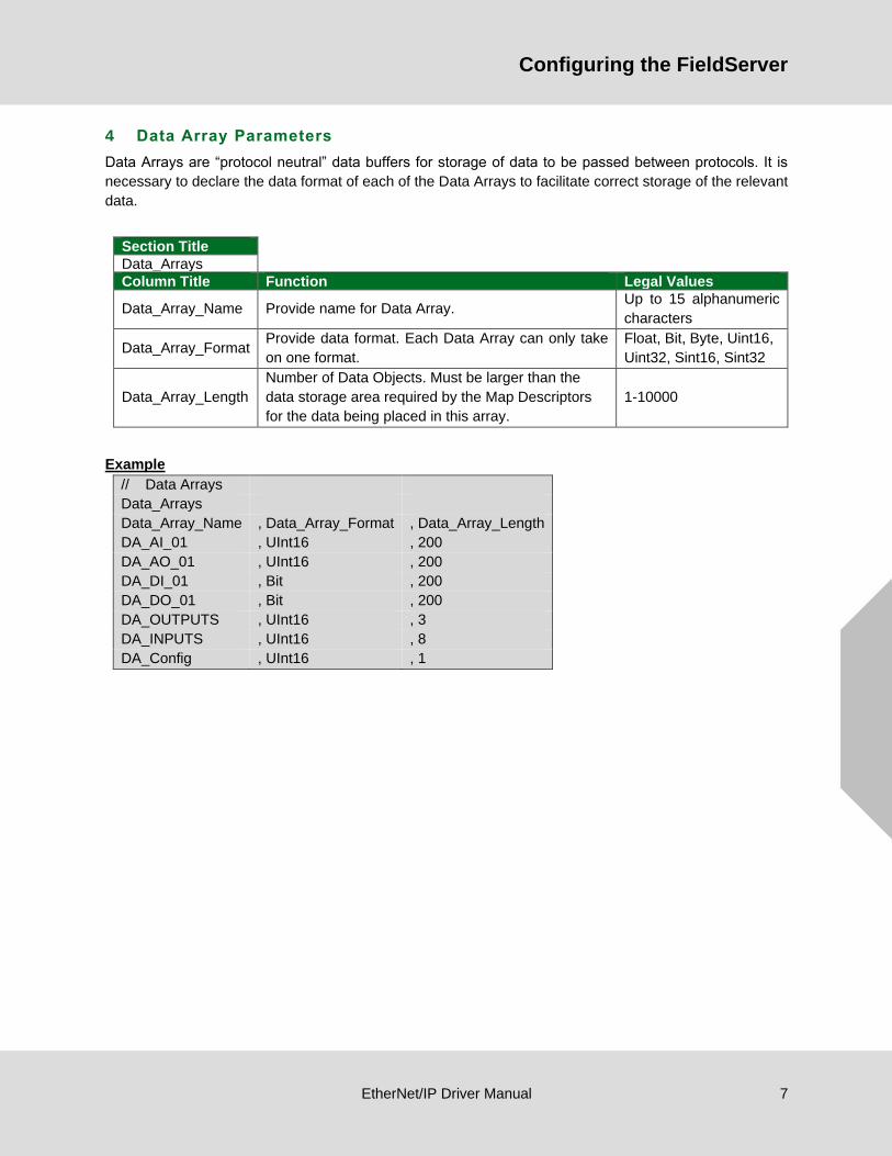
This section documents and describes the parameters necessary for configuring the FieldServer to
communicate with an EtherNet/IP Server.
The configuration file tells the FieldServer about its interfaces, and the routing of data required. In order to
enable the FieldServer for EtherNet/IP communications, the driver independent FieldServer buffers need
to be declared in the “Data Arrays” section, the destination device addresses need to be declared in the
“Client Side Nodes” section, and the data required from the servers needs to be mapped in the “Client Side
Map Descriptors” section. Details on how to do this can be found below.
NOTE: In the tables below, * indicates an optional parameter and bold legal values are default.
5.1 Client Side Connection Parameters
Section Title
Adapter
Column Title Function Legal Values
Adapter Adapter Name. N1, N2, WLAN1
Protocol Specify protocol used. EtherNet/IP
UDP_Local_IO_Port Specify if it is required to receive implicit IO
messages on the non-default port. 1-65534, 2222
Example
// Client Side Connections
Connections
Adapter , Protocol , UDP_Local_IO_Port
N1 , EtherNet/IP , 2222
1 Not all ports shown are necessarily supported by the hardware. Consult the appropriate Instruction manual for details of the ports
available on specific hardware.
Configuring the FieldServer
EtherNet/IP Driver Manual 9
5.2 Client Side Node Parameters
Section Title
Nodes2
Column Title Function Legal Values
Node_Name Provide name for node. Up to 32 alphanumeric
characters.
IP_Address Address of Server. Any valid address on
subnet.
Protocol Specify protocol used. EtherNet/IP
Adapter Specify port Adapter used. N1, N2, WLAN3
Plc_Type* Specify the type of remote PLC. Only required for PCCC
Services.
MicroLogix, SLC5,
PLC5
EIP_Cache_Connection* Specify if connection to remote server should be reused
or closed after every data transfer transaction. YES, NO
EIP_Skip_Cmd*
Some devices do not support all 'under the hood'
commands specified by the EIP driver.
Specify the command that should not be issued by the
FieldServer.
-, LIST_IDENTIFY
Example
// Client Side Nodes
Nodes
Node_Name , IP_Address , Adapter , Protocol
PLC 1 , 192.168.1.174 , N1 , EtherNet/IP
5.3 Client Side Map Descriptor Parameters
5.3.1 FieldServer Specific Map Descriptor Parameters
Column Title Function Legal Values
Map_Descriptor_Name Name of this Map Descriptor. Up to 32 alphanumeric characters
Data_Array_Name Name of Data Array where data is
to be stored in the FieldServer.
One of the Data Array names from
Section 4
Data_Array_Offset Starting location in Data Array. 0 to (Data_Array_Length -1) as
specified in Section 4
Function Function of Client Map Descriptor.
Rdbc, Wrbc, Wrbx
NOTE: It is possible with Data Table
Read on the Client side to read and
write to the same tag by using the
"Write Thru" property of the Rdbc
function.
2 Only one explicit connection is created per node. All explicit Map Descriptors for that node will use the same explicit connection. 3 Not all ports shown are necessarily supported by the hardware. Consult the appropriate Instruction manual for details of the ports
available on specific hardware.
Configuring the FieldServer
EtherNet/IP Driver Manual 10
5.3.2 Driver Related Map Descriptor Parameters
Unconnected Messages
Column Title Function Legal Values
EIP_Service The action to be performed. Get_Attrib, Set_Attrib
EIP_Class Class to be polled.
0-65535, default 0 (refer to
Section 10.2 for commonly
used classes)
EIP_Attribute Attribute associated with the class given.
0-255, default 0 (refer to
Section 10.2 for commonly
used attributes)
EIP_Con_Typ The type of data transfer required. Also referred
to as the “Transport Method”. Unconnected, Explicit
EIP_Path*
Used to stipulate the path to the CPU in certain
PLC’s. Paths vary and are dependent on the
structure of the network.
Any space delimited numerical
value. Refer to vendor’s
device documentation.
(Section 7.3)
EIP_Data_Type
This parameter should be used to force the data
type of the attribute to match the data type used
in the remote device.
Value Alias (as used in PLC)
Float REAL
Uint32 DINT
Uint16 INT
BYTE SINT
default INT
Length
Number of data elements to be mapped. If the
number of data elements exceeds the Map
Descriptor length, the list of data elements will be
truncated and an error message will be printed
once per Map Descriptor. Refer to Section 10 for
further information.
For any given Map Descriptor
there can be 200 Floats, 400
Integers or 800 Bytes.
Address Instance of the class to be polled. 0-65535, default 0
Configuring the FieldServer
EtherNet/IP Driver Manual 11
Data Table Read/Write
Column Title Function Legal Values
EIP_Service The action to be performed. Data_Table_Read,
Data_Table_Write
EIP_Con_Typ The type of data transfer required. Explicit, UnConnected
EIP_Path*
Used to stipulate the path to the CPU in
certain PLC’s. Paths vary and are
dependent on the structure of the network.
Any space delimited
numerical value. Refer to
vendor’s device
documentation. (Section
7.3)
EIP_Tag_Name
Tag name expressed in PLC program. The
data type of this parameter is used to set
the data format of the Data Array if the
EIP_DATA_TYPE parameter is not
specified.
Maximum length 48
characters
EIP_Data_Type*
This parameter can be used to force the
data type of the tag to match the data type
used in the remote device. If this parameter
is not specified the Data Type of the Data
Array will be used. Refer to Section 7.4 for
more information. Data Types can be
specified in either FieldServer or Rockwell
Data Type. Refer to Section 9.4 for more
information.
Value Alias (as used in PLC)
Float REAL
Uint32 DINT
Uint16 INT
BYTE SINT
BIT BOOL &
BOOLEAN
Length
Number of data elements to be mapped. If
the number of data elements exceeds the
Map Descriptor length, the list of data
elements will be truncated and an error
message will be printed once per Map
Descriptor. See Section 10 for further
information.
0 to (Data_Array_Length -1)
as specified in Section 4
EIP_Structure_Handle*
This parameter is required to read/write
structures. The driver supports read/write
structures having members of same type, i.e.
all members are of type Byte, UINT16,
UINT32 or Float etc.
When this parameter is defined, the number
of structure members must be specified as
the length of the Map Descriptor. Refer to
Section 7.7 for more information.
Any 16bit Integer number
(e.g. 59592), 0
Configuring the FieldServer
EtherNet/IP Driver Manual 12
PCCC
Column Title Function Legal Values
EIP_Service Action to be performed. Exec_PCCC (encapsulation using
Allen Bradley PCCC)
EIP_Con_Typ The type of data transfer required. Explicit
EIP_Path*
Used to stipulate the path to the CPU in
certain PLC’s. Paths vary and are dependent
on the structure of the network.
Any space delimited numerical
value. Refer to vendor’s device
documentation. Also see Section
7.3, 0 0.
File_Type Allen Bradley file type.
N Integer
F Float
O Output
B Boolean
I Input
S Status
File_Number Allen Bradley file number. Any valid numerical value
Length
Number of data elements to be mapped. If the
number of data elements exceeds the Map
Descriptor length, the list of data elements will
be truncated and an error message will be
printed once per Map Descriptor. Refer to
Section 10 for further information.
For any given Map Descriptor there
can be 200 floats, 400 integers or
800 bytes
Address Address in the file. Any valid numerical value between 0
to 255
Implicit IO Messages
Column Title Function Legal Values
EIP_Con_Typ The type of data transfer required. Also
referred to as the “Transport Method”. Implicit
EIP_Class EIP class to be polled.
Integer value. In most cases it
will be the assembly class (i.e.
value will be 4)
Address Production/Consumption connection
point or Instance of the class.
Integer value depending upon
server configuration
Length Number of data items to be polled.
For any given Map Descriptor
there can be 125 floats/32bit
integers, 250 integers or 500
bytes
Parent_Map_Descriptor
Specify the name of previously created
Map Descriptor to which this Map
Descriptor should be linked.
Use – for no setting, or specify
name of other Map Descriptor
EIP_Real_Time_Format Specify if real time format is 'HeartBeat'. Heartbeat, -
5.3.3 Timing Parameters
Column Title Function Legal Values
Scan_Interval* Rate at which data is polled. ≥0.001s
• Map_Descriptor_Name – The config Map Descriptor (Rockwell calls it Configuration) is optional
for FieldServer (as per EIP specs), but it is used by Controllogix and technically it is an instance
of Assembly Class.
• Address – The address numbers are random but should be according to Server information; at
what numbers server will consume and produce data.
• Parent_Map_Descriptor – To open an implicit connection, both Producer and Consumer
connection information is required. Producer is an active Map Descriptor, so consumer should be
linked to producer.
• EIP_Real_Time_Format – If not used or set to “-“: The FieldServer and remote server both act
as producer/ consumer endpoints. If set to 'Heartbeat' on wrbc MD: The FieldServer acts as a
consumer only endpoint that produces the heartbeat; the remote server acts as a producer only
end point. If set to 'HeartBeat' on passive MD: The FieldServer acts as a producer only
endpoint and remote server acts as a consumer only endpoint that generates a heartbeat.
Configuring the FieldServer
EtherNet/IP Driver Manual 14
6 Server Side Configuration
For detailed information on FieldServer configuration, refer to the FieldServer Configuration Manual. The
information that follows describes how to expand upon the factory defaults provided in the configuration
files included with the FieldServer (see “.csv” files provided with the FieldServer).
This section documents and describes the parameters necessary for configuring the FieldServer to
communicate with an EtherNet/IP Client.
The configuration file tells the FieldServer about its interfaces, and the routing of data required. In order to
enable the FieldServer for EtherNet/IP communications, the driver independent FieldServer buffers need
need to be declared in the “Data Arrays” section, the FieldServer virtual node(s) needs to be declared in
the “Server Side Nodes” section, and the data to be provided to the client needs to be mapped in the “Server
Side Map Descriptors” section. Details on how to do this can be found below.
NOTE: In the tables below, * indicates an optional parameter, with the bold legal value as default.
6.1 Server Side Connection Parameters
Section Title
Connections
Column Title Function Legal Values
Adapter Adapter Name N1, N2, WLAN4
Protocol Specify protocol used. EtherNet/IP
UDP_Local_IO_Port Specify if it is required to receive implicit IO messages on the
non-default port. 1-65534, 2222
Example
// Server Side Connections
Connections
Adapter , Protocol , UDP_Local_IO_Port
N1 , EtherNet/IP , 2222
6.2 Server Side Node Parameters
Section Title
Nodes5
Column Title Function Legal Values
Node_Name Provide name for Node. Up to 32 alphanumeric
characters
Protocol Specify protocol used. EtherNet/IP
Server_Hold_
Timeout*
Specifies time FieldServer will reserve server side connection while
waiting for the Client side to update data. >1.0s
IP_Address
Specify multicast IP Address to which the production data should
be sent. It will be used only if client requested multicast connection.
This parameter is only required for Implicit IO Messages.
IP Address
Example
// Server Side Nodes
Nodes
Node_Name , Protocol
EIP_01 , EtherNet/IP
4 Not all ports shown are necessarily supported by the hardware. Consult the appropriate Instruction manual for details of the ports
available on specific hardware. 5 Only one explicit connection is created per node. All explicit Map Descriptors for the node use the same explicit connection.
Configuring the FieldServer
EtherNet/IP Driver Manual 15
6.3 Server Side Map Descriptor Parameters
6.3.1 FieldServer Specific Map Descriptor Parameters
Column Title Function Legal Values
Map_Descriptor_Name Name of this Map Descriptor. Up to 32 alphanumeric
characters
Data_Array_Name Name of Data Array where data is to be stored in
the FieldServer.
One of the Data Array
names from Section 4
Data_Array_Offset Starting location in Data Array. 0 to maximum as
specified in Section 4
Function Function of Server Map Descriptor. Passive
Server_Hold_Timeout*
Specifies the length of time that the FieldServer will
reserve the Server side connection while waiting
for the Client side to update data in Data Array (if
necessary).
>1.0s
6.3.2 Driver Related Map Descriptor Parameters
Unconnected Messages
Column Title Function Legal Values
EIP_Service The action to be performed. Get_Attrib, Set_Attrib
EIP_Class Class to be served.
0-65535, default 0 (refer
to Section 10.2 for
commonly used classes)
EIP_Attribute Attribute associated with the class served.
0-255, default 0 (refer to
Section 10.2 for
commonly used
attributes)
EIP_Data_Type
This parameter should be used to force the data type of
the attribute to match the data type used in the remote
device.
Value Alias (as used in
PLC)
Float REAL
Uint32 DINT
Uint16 INT
BYTE SINT
default INT
Length
Number of data elements to be mapped. If the number of
data elements exceeds the Map Descriptor length, the
list of data elements will be truncated and an error
message will be printed once per Map Descriptor. Refer
to Section 10 for further information.
For any given Map
Descriptor there can be
200 floats, 400 integers
or 800 bytes
Address Instance of the class to be served. 0-65535, default 0
Configuring the FieldServer
EtherNet/IP Driver Manual 16
Data Table Read/Write
Column Title Function Legal Values
EIP_Service The action to be performed.
Data_Table_Read,
Data_Table_Write
NOTE: Separate Map
Descriptors need to be
configured for each
service.
EIP_Tag_Name
Tag name expressed in PLC program. The data
type of this parameter is used to set the data format
of the Data Array if the EIP_Data_Type parameter
is not specified.
Maximum length 48
characters
EIP_Data_Type*
If set, the data will be stored in the specified format
which may be different to the format of the tag
being polled. If the parameter is not set, the data
type of the Data Array will be used. This is only
applicable to Data Table Read when FieldServer is
the Server. Refer to Section 7.4 for further
information.
Float, Uint16, Uint32,
Bit, Byte, Boolean, -
Length
Number of data elements to be mapped. If the
number of data elements exceeds the Map
Descriptor length, the list of data elements will be
truncated and an error message will be printed
once per Map Descriptor. Refer to Section 10 for
further information.
0 to (Data_Array_Length
-1) as specified in
Section 4
EIP_Structure_Handle*
This parameter is required only for read structures
i.e. where EIP_Service is Data_Table_Read. The
driver supports read structures having members of
same type, i.e. all members are of type Byte,
Uint16, Uint32 or Float, etc. When this parameter
is defined, the number of structure members must
be specified as the length of the Map Descriptor.
Any 16bit Integer
number e.g. 59592, 0
Configuring the FieldServer
EtherNet/IP Driver Manual 17
PCCC
Column Title Function Legal Values
EIP_Con_Typ The type of data transfer required. Explicit
EIP_Service Action to be performed.
EXEC_PCCC
(encapsulation using
Allen Bradley PCCC)
File_Type Allen Bradley file type.
N Integer
F Float
O Output
B Boolean
I Input
S Status
File_Number Allen Bradley file number. Any valid numerical
value
Length
Number of data elements to be mapped. If the
number of data elements exceeds the Map
Descriptor length, the list of data elements will be
truncated and an error message will be printed
once per Map Descriptor. Refer to Section 10 for
further information.
For any given Map
Descriptor there can be
61 floats, 122 integers or
244 bytes
Address Address in the file. Any valid numerical
value between 0 to 255
Implicit IO Messages
Column Title Function Legal Values
EIP_Con_Typ The type of data transfer required. Also referred to
as the “Transport Method”. Implicit
EIP_Class Class to be served.
Integer value
(in most cases it will be
the assembly class i.e.
4)
EIP_Attribute Attribute associated with the class served.
Integer value. In most
cases it will be data
attribute 3. Refer to
Section 10.2 for legal
attribute values
Length Number of data elements to be mapped. 1 to Data Array length
Address Production or Consumption connection point
address. Any integer number
EIP_IO_Type Input means the FieldServer consumes data and
Output means the FieldServer produces data. Input, Output
• EIP_TAG_NAME – FieldServer Tag names that will be called in the PLC Message Block. The
names must match what is written in the Message block in the PLC exactly.
NOTE: The corresponding PLC Tag Name can be different and probably will be. See Message
Block Below.
• Length – Number of data points made available for reading or writing within the Tag.
6 The Data Format should match the Data Type used in the PLC program and tags to prevent a mismatch in the display of the Data
Values.
Additional Information
EtherNet/IP Driver Manual 21
7.5.2 The PLC Program
The PLC program example below shows the minimum steps necessary to program communications with
the FieldServer. Depending on the real intended application, additional steps may be necessary for
completeness.
Step 1: Configure tags in the PLC for storing FieldServer read and write data.
Step 2: Configure message tags for storage of message block data.
Step 3: Write ladder logic to exercise a read and write message block.
NOTE: It is important to use the ladder logic to ensure that only one message block can be
executing at any time.
Step 4: Configure the properties for the two message blocks by clicking on the “…” button.
Tag length must be equal to or greater than the number of points being written/read.
MESSAGE data type must be used.
Avoid using UDT Types. The data will be read but the exact placement of the data in the tags and arrays will be hard to determine.
The logic shown will cause the PLC to poll the FieldServer at a very high speed. This may overload network traffic - logic that schedules the communication at a slower rate is generally more advisable.
Additional Information
EtherNet/IP Driver Manual 22
Read Message Block
Write Message Block
Communication Tab (for both message blocks)
NOTE:
• A message block only executes on the leading edge of a rung condition.
• No more than one message block executes at a time.
Step 5: Download the program and set the PLC to Run Mode.
Remote FieldServer tag configured in the FieldServer (see example above).
Local PLC tag configured in the PLC tag list (see example above).
Local PLC tag configured in the PLC tag list (see example above).
Remote FieldServer tag configured in the FieldServer (see example above).
Number of points transferred from FieldServer to PLC regardless of tag and array sizes.
Number of points transferred from PLC to FieldServer regardless of tag and array sizes.
EIP_Card is the name of the Ethernet ENBT Card in the ControlLogix Rack. “2” refers to the port number on the ENBT Card. 192.168.1.75 is the IP Address of the FieldServer.
The tag tab requires no configuration.
Uncheck for ‘UnConnected’ communication to FieldServer.
Additional Information
EtherNet/IP Driver Manual 23
7.6 Configuring a FieldServer to Read/Write Data to/from a PLC with Explicit Messaging
This example makes use of the Data Table Read/Write method for passing data between the FieldServer
and an Allen Bradley PLC. The example shows configuration of a ControlLogix PLC, but all RockWell PLC’s
that support EtherNet/IP communications and Data Table Read/Write operations in Message blocks should
be able to communicate this way. These map descriptors will create an explicit connection to the server
and will then transfer data in the data table format. The EIP_Tag_Name field contains the tag name
referenced in the server and the EIP_Path field represents the path (through different ports) to the server.
Each port jump is separated by a space. This field generally holds a backplane/cpu slot combination.
DATA_TABLE_READ and DATA_TABLE_WRITE are the only legal values for EIP_SERVICE.
Note that this is by far the preferred method for communicating with Allen Bradley PLC’s due to its ease of
configuration, quantity of data that can be transferred and speed of transfer.
When the FieldServer is the active component as shown below (i.e: the FieldServer Polls the PLC and not
the other way around), then very little programming is needed in the PLC, other than the Tag Creation and