Driver Version: 1.03 Document Revision: 1 A Sierra Monitor Company APPLICABILITY & EFFECTIVITY Effective for all systems manufactured after October 2009 Driver Manual (Supplement to the FieldServer Instruction Manual) FS-8700-45 Grinnell TFX Minerva
Transcript
Driver Version: 1.03
Document Revision: 1
A Sierra Monitor Company
APPLICABILITY & EFFECTIVITY
Effective for all systems manufactured after October 2009
Driver Manual
(Supplement to the FieldServer Instruction Manual)
FS-8700-45 Grinnell TFX Minerva
FS-8700-45 Grinnell TFX Minerva Manual Table of Contents
4 Data Array Parameters ................................................................................................................................... 5
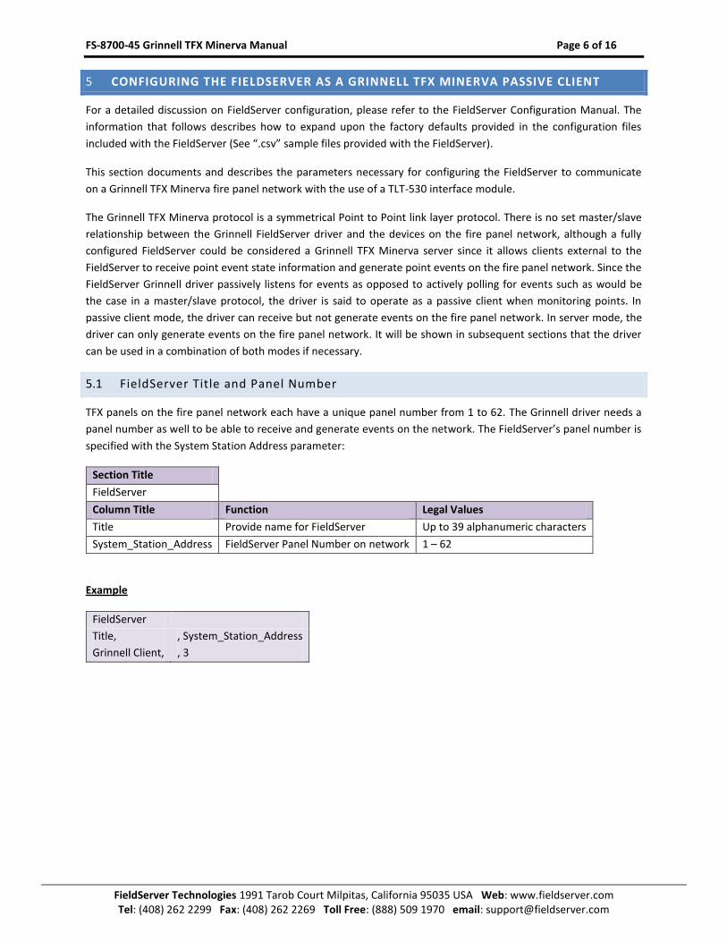
5 Configuring the FieldServer as a Grinnell TFX Minerva Passive Client ............................................................. 6
5.1 FieldServer Title and Panel Number .............................................................................................................. 6
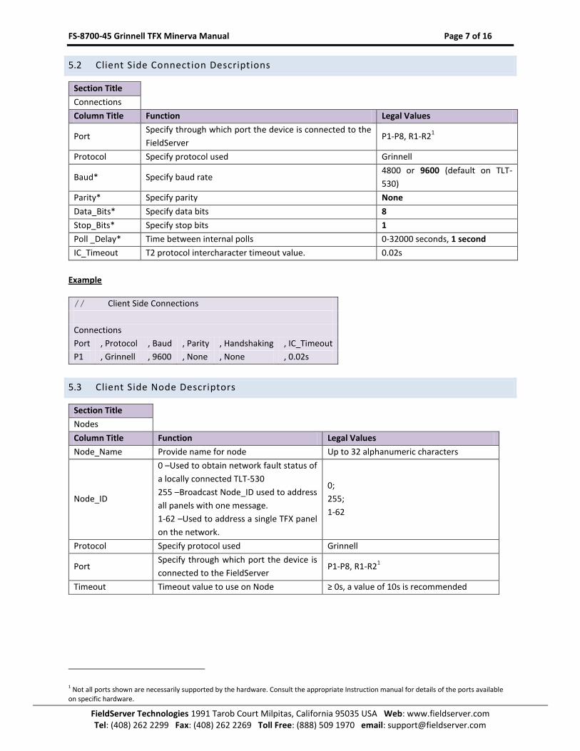
5.2 Client Side Connection Descriptions .............................................................................................................. 7
5.3 Client Side Node Descriptors ......................................................................................................................... 7
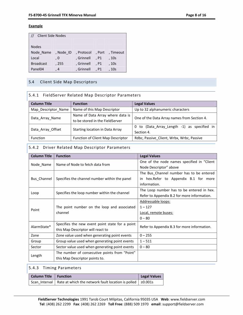
5.4 Client Side Map Descriptors........................................................................................................................... 8
5.4.1 FieldServer Related Map Descriptor Parameters ................................................................................... 8
5.4.2 Driver Related Map Descriptor Parameters ........................................................................................... 8
5.4.4 Map Descriptor Example 1 - Monitoring the TLT-530 interface’s network fault status ......................... 9
5.4.5 Map Descriptor Example 2 - Monitoring points on a TFX panel and storing all new point event states
10
5.4.6 Example 3 - Monitoring points on a TFX panel and storing only specific point event states ............... 10
5.4.7 Map Descriptor Example 4 - Generating Point Events on the TFX network ......................................... 11
Appendix A. Useful Features ................................................................................................................................ 12
Appendix B. Reference ........................................................................................................................................ 13
Appendix B.1. Bus Channel ...................................................................................................................................... 13
Data Arrays are “protocol neutral” data buffers for storage of data to be passed between protocols. It is necessary to declare the data format of each of the Data Arrays to facilitate correct storage of the relevant data.
Section Title
Data_Arrays
Column Title Function Legal Values
Data_Array_Name Provide name for Data Array Up to 15 alphanumeric characters
Data_Array_Format Provide data format. Each Data Array can only take on
one format.
Float, Bit, UInt16, SInt16,
Packed_Bit, Byte, Packed_Byte,
Swapped_Byte
Data_Array_Length
Number of Data Objects. Must be larger than the data
storage area required by the Map Descriptors for the
data being placed in this array.
1-10, 000
Example
// Data Arrays
Data_Arrays
Data_Array_Name , Data_Format , Data_Array_Length
Network_Fault , Byte , 1
Point_St_Values , Byte , 2
Point_States , Bit , 190
FS-8700-45 Grinnell TFX Minerva Manual Page 6 of 16
Node_Name Provide name for node Up to 32 alphanumeric characters
Node_ID
0 –Used to obtain network fault status of
a locally connected TLT-530
255 –Broadcast Node_ID used to address
all panels with one message.
1-62 –Used to address a single TFX panel
on the network.
0;
255;
1-62
Protocol Specify protocol used Grinnell
Port Specify through which port the device is
connected to the FieldServer P1-P8, R1-R2
1
Timeout Timeout value to use on Node ≥ 0s, a value of 10s is recommended
1 Not all ports shown are necessarily supported by the hardware. Consult the appropriate Instruction manual for details of the ports available on specific hardware.
FS-8700-45 Grinnell TFX Minerva Manual Page 8 of 16
5.4.4 Map Descriptor Example 1 - Monitoring the TLT-530 interface’s network fault status
The Client driver allows an actively polling Map Descriptor to monitor the TFX network health. This Map Descriptor periodically reads the TFX network’s fault status. The
TLT-530 monitors the attached TFX network and returns a fault status message if polled. A Scan_Interval of 10s is recommended to to provide a good indication of
network health without cluttering the network. This active Map Descriptor is typically used when it is necessary to maintain link integrity with the TLT-530. The
FieldServer will report the link going offline when the TLT-530 stops responding to the polling Map Descriptor.
Alternatively or in addition the following Server Map Descriptor could be used which will be updated with a network fault value from the TLT-530 should the network’s
fault status change. Note that the use of only a Server Map Descriptor to monitor network fault status will result in a loss of link integrity monitoring since the update
message is sent asynchronously from the TLT-530 when the network’s fault status change.
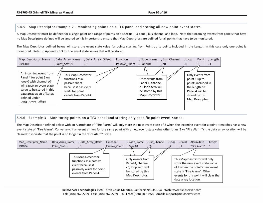
5.4.5 Map Descriptor Example 2 - Monitoring points on a TFX panel and storing all new point event states
A Map Descriptor must be defined for a single point or a range of points on a specific TFX panel, bus channel and loop. Note that incoming events from panels that have
no Map Descriptors defined will be ignored so it is important to ensure that Map Descriptors are defined for all points that have to be monitored.
The Map Descriptor defined below will store the event state value for points starting from Point up to points included in the Length. In this case only one point is
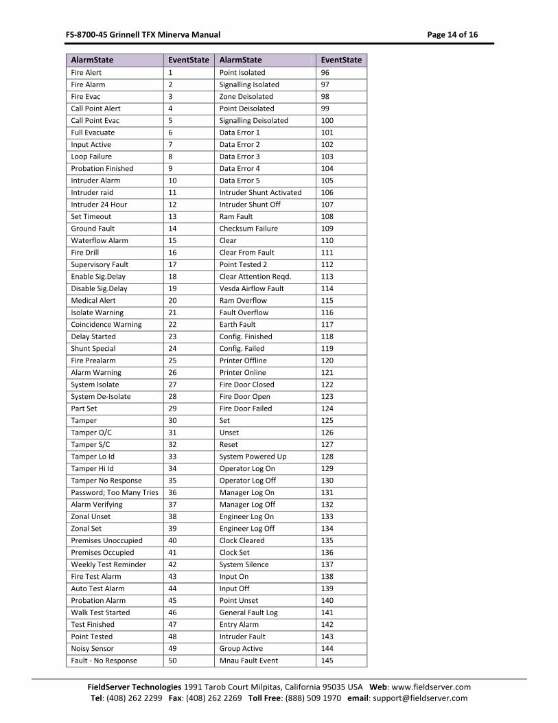
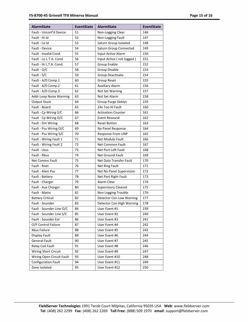
monitored. Refer to Appendix B.3 for the event state values that will be stored.
Map_Descriptor_Name , Data_Array_Name , Data_Array_Offset , Function , Node_Name , Bus_Channel , Loop , Point , Length
5.4.6 Example 3 - Monitoring points on a TFX panel and storing only specific point event states
The Map Descriptor defined below with an AlarmState of “Fire Alarm” will only store the new event state of 2 when the incoming event for a point it matches has a new
event state of “Fire Alarm”. Conversely, if an event arrives for the same point with a new event state value other than (2 or “Fire Alarm”), the data array location will be
cleared to indicate that the point is no longer in the “Fire Alarm” state.
Map_Descriptor_Name , Data_Array_Name , Data_Array_Offset Function , Node_Name , Bus_Channel , Loop , Point AlarmState Length
An incoming event from Panel 4 for point 1 on loop 0 with channel c0 will cause an event state value to be stored in this data array at an offset as defined under Data_Array_Offset
This Map Descriptor functions as a passive client because it passively waits for point events from Panel 4.
Only events from Panel 4, channel c0, loop zero will be stored by this Map Descriptor.
Only events from point 1 up to points included in the length on Panel 4 will be stored by this Map Descriptor.
This Map Descriptor functions as a passive client because it passively waits for point events from Panel 4.
This Map Descriptor will only store the new event state value of 2 when the point’s new event state is “Fire Alarm”. Other events for this point will clear the data array location.
Only events from Panel 4, channel c0, loop zero will be stored by this Map Descriptor.
FS-8700-45 Grinnell TFX Minerva Manual Page 11 of 16
5.4.7 Map Descriptor Example 4 - Generating Point Events on the TFX network
To generate point events on the network, Map Descriptors with a write-type function have to be used. A Wrbx function Map Descriptor may be used to generate an
event when the Data Array location referenced by the Map Descriptor is written to. A Wrbc function Map Descriptor may be used to continuously generate an event
every scan interval seconds. When using a Wrbc function Map Descriptor, a scan interval value of 10s or greater is recommended to prevent flooding the communications
channel with messages.
5.4.7.1 Extended Event Messages
Extended Event Messages are sent in broadcast mode to all panels on the network. A node ID of 255 on a Map Descriptor will cause a message to be sent in broadcast
mode. The Broadcast’s Node_ID must be defined as 255 under Section 5.3
Map_Descriptor_Name , Data_Array_Name , Data_Array_Offset , Function , Node_Name , Bus_Channel , Loop , Point , Group , Sector , Zone , Length
Event log messages are sent to a specific panel on the network. A node ID of 1 to 62 on a Map Descriptor will cause a message to be sent directly to the panel with
number the same as the node ID.
When writing an event value into the data array at data array offset, the following Map Descriptor will cause an event log message to be sent to Panel with number 4.
(provided Panel04 ‘s node ID was defined to be 4 as well).
Map_Descriptor_Name , Data_Array_Name , Data_Array_Offset , Function , Node_Name , Bus_Channel , Loop , Point , Group , Sector , Zone , Length