Page 1
DRIVER/OPERATOR - PUMPERNFPA 1002
The following lesson plans for Apparatus Driver/Operator - Pumper are based on NFPA 1002, Standard for Fire Department Vehicle Driver/Operator Professional, 1993 Edition. These lesson plans contain the same material that is covered in the Career Development Course for Driver/Operator Pumper. The material in these lesson plans follows natural learning simple to complex sequencing practices. Therefore, mastery of the material in the beginning is required before advancing to the latter lesson plans. The sequence of material in these detailed lesson plans is different from the Career Development Course and NFPA 1002 sequence, which were designed to serve other purposes.
It is recommended that you become familiar with NFPA 1002, Standard for Fire Department Vehicle Driver/Operator Professional Qualifications prior to using these lesson plans. The following list identifies all Lesson Plans and the related NFPA 1002 Job Performance Requirements. Note that if some of the numbers appear more than once; this is because several of the Job Performance Requirements or their prerequisites have to be broken in parts and taught at different times. Finally, if only the Job Performance Requirement number is identified, then all the prerequisite knowledge and skills are covered in that lesson.
Lesson Plan 12-2.12-2.1
Lesson Plan 22-3.1 2-3.3.22-3.1.1 2-3.42-3.1.2 2-3.52-3.2.1 2-3.62-3.2.2 2-3.6.12.3.3 2-3.82-3.3.1
Lesson Plan 33-1.23-1.33-1.43-1.5
Lesson Plan 43-2.13-2.1.1
Lesson Plan 53-3.13-3.1.1
Lesson Plan 63-4.1 3-4.23-4.1.1 3-4.33-4.1.2 3-4.4
Apparatus Driver/Operator - Pumper 1 Lesson Plan 1
Page 2
DOD FIRE SERVICE CERTIFICATION SYSTEM
LESSON PLAN 1
Personnel Classification: Apparatus/Driver Operator - Pumper
Subject: Preventive Maintenance
NFPA 1002 Objectives
2-2.12-2.2
Training Materials/Equipment:
Pumper vehicle, service records used by the agency, including fire apparatus history card
References:
IFSTA, Fire Department Pumping Apparatus, 7th Edition, 1989, Fire Protection Publications, Oklahoma State University.
IFSTA, Fire Stream Practices, 7th Edition, 1989, Fire Protection Publications, Oklahoma State University.
IFSTA, Water Supplies for Fire Protection, 4th Edition, 1988, Fire Protection Publications, Oklahoma State University.
NFPA 1002: Fire Vehicle Operator Professional Qualifications, 1993 National Fire Protection Association, Quincy, Massachusetts
NFPA 1500: Standard on Fire Department Occupational Safety and Health Programs, 1992 National Fire Protection Association, Quincy, Massachusetts
Additional Information:
IFSTA Firefighter Videotape Series - Fire Pump Operation and Maintenance, Fire Protection Publications, Oklahoma State University
Apparatus Driver/Operator - Pumper 2 Lesson Plan 1
Page 3
Instructor Tasks
• Review lesson outline to ensure understanding of contents and procedures.
• Review references for lesson.
• Use additional references and your knowledge to enrich lesson outline.
• Select and prepare any additional audio-visual aids that may assist in the presentation of the lesson.
• Ensure that all equipment needed, including any audio-visual equipment, is available.
• Review lesson at end of session to ensure student understanding.
• Ensure that the topics and objectives of the lesson have been adequately covered.
Apparatus Driver/Operator - Pumper 3 Lesson Plan 1
Page 4
INTRODUCTION AND OBJECTIVES
I. Greet class
II. State purpose of the lesson
III. Establish relation to previous and following lessons
IV. Review NFPA 1002 objectives for this lesson
V. Review any additional materials for this lesson
PRESENTATION
LESSON OUTLINE INSTRUCTOR NOTES
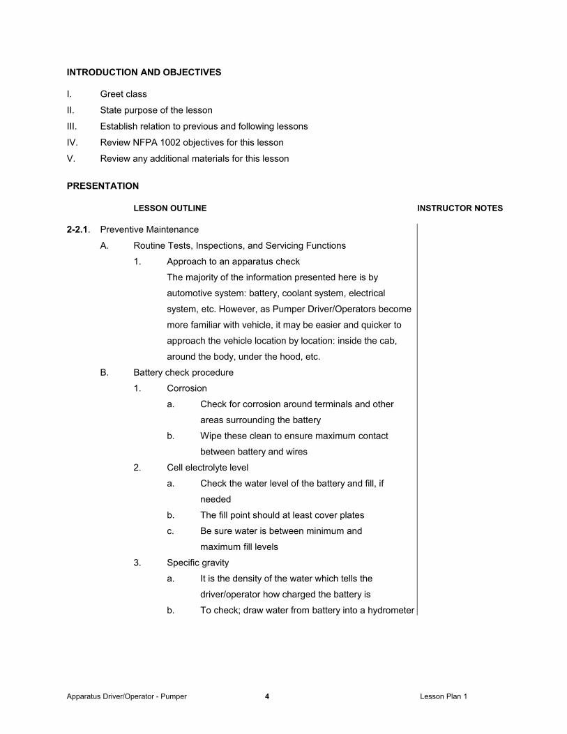
2-2.1. Preventive Maintenance
A. Routine Tests, Inspections, and Servicing Functions
1. Approach to an apparatus check
The majority of the information presented here is by
automotive system: battery, coolant system, electrical
system, etc. However, as Pumper Driver/Operators become
more familiar with vehicle, it may be easier and quicker to
approach the vehicle location by location: inside the cab,
around the body, under the hood, etc.
B. Battery check procedure
1. Corrosion
a. Check for corrosion around terminals and other
areas surrounding the battery
b. Wipe these clean to ensure maximum contact
between battery and wires
2. Cell electrolyte level
a. Check the water level of the battery and fill, if
needed
b. The fill point should at least cover plates
c. Be sure water is between minimum and
maximum fill levels
3. Specific gravity
a. It is the density of the water which tells the
driver/operator how charged the battery is
b. To check; draw water from battery into a hydrometer
Apparatus Driver/Operator - Pumper 4 Lesson Plan 1
Page 5
LESSON OUTLINE INSTRUCTOR NOTES
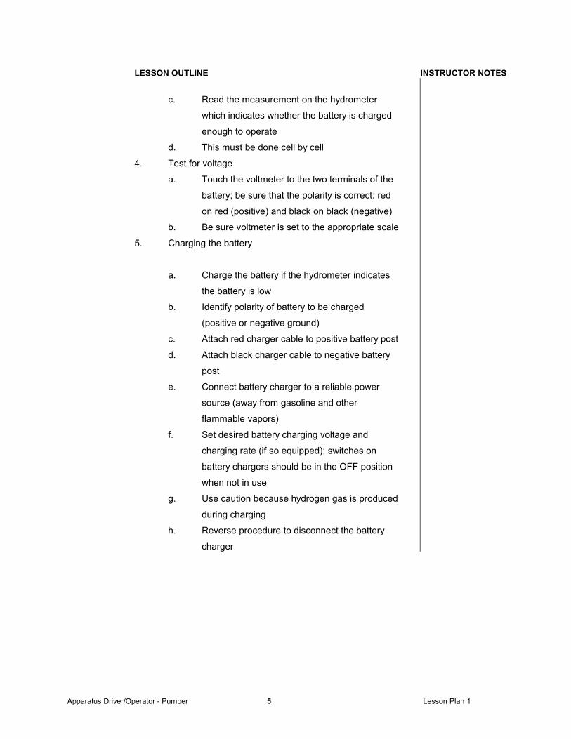
c. Read the measurement on the hydrometer
which indicates whether the battery is charged
enough to operate
d. This must be done cell by cell
4. Test for voltage
a. Touch the voltmeter to the two terminals of the
battery; be sure that the polarity is correct: red
on red (positive) and black on black (negative)
b. Be sure voltmeter is set to the appropriate scale
5. Charging the battery
a. Charge the battery if the hydrometer indicates
the battery is low
b. Identify polarity of battery to be charged
(positive or negative ground)
c. Attach red charger cable to positive battery post
d. Attach black charger cable to negative battery
post
e. Connect battery charger to a reliable power
source (away from gasoline and other
flammable vapors)
f. Set desired battery charging voltage and
charging rate (if so equipped); switches on
battery chargers should be in the OFF position
when not in use
g. Use caution because hydrogen gas is produced
during charging
h. Reverse procedure to disconnect the battery
charger
Apparatus Driver/Operator - Pumper 5 Lesson Plan 1
Page 6
LESSON OUTLINE INSTRUCTOR NOTES
C. Brake system
1. Air brakes
a. Pressure test by tapping the brake pedal
b. Check low air warning system
c. Check air chuck on rear of apparatus
2. Emergency brakes
a. Check emergency brakes (hand brakes) for hold
D. Coolant system
1. The coolant system protects both engine and pump
2. For safety, be sure coolant is checked when the engine is
entirely cool
3. Procedure
a. Check the coolant color and level in the radiator and
add fluid (if applicable)
b. Inspect the hoses for cracks or leaks
c. Flush the coolant system and add rust inhibitor (if
applicable)
d. Check the radiator fan for loose or cracked
blades
e. Check temperature gage reading with engine
running
E. Electrical system
1. There are numerous electrical connections in an apparatus;
damage from moisture or corrosion can render an electrical
connection inoperative
2. Lights
a. Operate headlight dimmer switch
b. Operate clearance, stop, and back up lights
c. Operate all compartment lights and switches
d. Operate warning lights and switches
e. Operate the floodlights and switches
3. All motor-driven equipment should be started and run
once a week
a. Operate rotating lights
b. Operate hose reel rewind
Apparatus Driver/Operator - Pumper 6 Lesson Plan 1
Page 7
LESSON OUTLINE INSTRUCTOR NOTES
c. Operate apparatus controls
d. Operate header and defroster fan
e. Operate heater and/or air conditioner
(if applicable)
f. Operate public address system and radio
g. Operate horn
h. Check audible and usual warning devices
F. Fuel system
1. A full tank of fuel; ensures maximum running time
2. Procedure
a. Check fuel level, add fuel if needed
b. Check fuel pumps and filters periodically
c. Check fuel tank cap vent for blockage, clear
if necessary
d. Drain moisture from fuel/water separator
G. Hydraulic fluids
1. Be certain the fluid added is compatible with the fluid already
in the reservoir; type of fluid needed is often printed on
reservoir or check appropriate Technical Order
2. Procedure
a. Wipe off lid of reservoir before opening to prevent
contamination from water or other contaminants
b. Amount to be filled is also found in the appropriate
Technical Order
c. Check master cylinder reservoir
d. Check power steering fluid reservoir
(if applicable)
H. Lubrication/oil levels
1. General
a. Prime objective of good maintenance
b. Proper lubrication saves maintenance and
repair dollars; reduces out-of-service time
Apparatus Driver/Operator - Pumper 7 Lesson Plan 1
Page 8
LESSON OUTLINE INSTRUCTOR NOTES
c. Oil gives protection against corrosion, foaming,
sludging, and carbon accumulation
d. To protect oil from contamination, prevent any
unnecessary engine starts
2. Procedure
a. Check technical order for correct viscosity of the oil
b. Check engine oil level
c. Check exterior of engine for leaks
d. Check transmission oil level
e. Check exterior of transmission for leaks
f. Check all oil lines for leaks, corrosion or damage
g. Check differential oil levels
h. Check oil pressure with engine running
I. Tires
1. Check tires for cuts, breaks, proper inflation, and
uneven wear
2. Check valve stems for corrosion or damage
3. Inflate tires to proper level as noted on tire
4. Check lugs for tightness and rims for damage
J. Steering system
1. Check steering gear for excessive motion and periodically
lubricate steering gear
2. Check seals on steering gear
3. Check fluid reservoir, add fluid if needed
4. Check all lines and hoses for damage
K. Belts
1. Check to make sure belts are present
2. Check belts for wear
3. Check for proper tension
Apparatus Driver/Operator - Pumper 8 Lesson Plan 1
Page 9
LESSON OUTLINE INSTRUCTOR NOTES
L. Tools, appliances, and equipment
1. General
a. Tools, appliances, and equipment refer to those
items carried on the fire apparatus but not
permanently attached to or a part of the apparatus
b. Most removable equipment is common to all fire
equipment and should be checked daily
2. Procedure
a. Remove and (if applicable) clean any equipment
attached to the apparatus
b. Check portable extinguishers by weighing or
checking pressure gauge
c. Check hose loads for correct finishes
d. Inventory all nozzles and appliances
e. Check air pressure in self-contained breathing
apparatus and spare bottles
f. Examine regulators and face pieces
g. Operate hand lights
h. Operate power tools
i. Operate hand tools
j. Check ground ladders
k. Check that the first-aid kit is complete
l. Check all tool mountings
m. Check fluid levels of all power tools/equipment
M. Agent tank level
1. Check the water level by shining a flashlight onto water
surface
2. Fill the agent tank to capacity
a. This should be done daily
b. At no time should tank be less than full
3. Check the inside surface for corrosion and cleanliness
4. Check the accuracy of agent level gauges compared to
actual agent levels in the tank
a. If there is a difference between the two, alert appropriate maintenance facility immediately
Apparatus Driver/Operator - Pumper 9 Lesson Plan 1
Page 10
LESSON OUTLINE INSTRUCTOR NOTES
N. Cab and Body
1. Check operation and condition of compartment doors
2. Check weather seals around cab and compartment
doors
3. Check windshield washer solvent, add if needed
4. Operate windshield wipers and washers
5. Check mirror adjustment
6. Inspect all glass for breaks or discoloration
7. Check operation of seat adjusting mechanisms
8. Check condition and operation of seat belts
O. Other components to check while inside cab
1. Check mirrors for cracks and cleanliness
2. Check map case is complete with grid maps and other
applicable maps
3. Check seats for tears and adjustibility
P. Water and Foam Piping
1. Check underside of apparatus for leaks
2. Check drain valves
3. Check oil level for priming pump
Q. Other components to check on the body of the apparatus
1. General
a. Fire apparatus must be kept clean.
b. A clean apparatus engine permits proper inspection
and ensures efficient operation as needed
2. Procedure
a. Check the body for cleanliness and wash away any
visible dirt
b. Check for oil, moisture, dirt, and grime
c. Check body panels for rust, dents, or exposed areas
needing touch-up paint
d. Check weather seals around cab and compartment
doors for looseness, damage, and deterioration
Apparatus Driver/Operator - Pumper 10 Lesson Plan 1
Page 11
LESSON OUTLINE INSTRUCTOR NOTES
2-2.2 Document routine tests, inspections, and service functions
A. Fire apparatus record
1. Maintain as required
B. Fire apparatus data and history
1. Maintain as required
C. Gasoline, oil and mileage record
1. Maintain as required
D. Apparatus inspection report
1. Complete as required
a. Daily
b. Weekly
c. Periodic
E. Fire equipment record
1. Complete as required
a. Daily
b. Weekly
c. Periodic
REVIEW
I. Discuss key lesson points.
II. Ask questions on the material covered.
III. Review material that may be unclear.
IV. Administer test or quiz.
V. Critique test or quiz.
SUMMARY
I. Summarize what has been covered.
II. Relate what has been covered to the next lesson.
Apparatus Driver/Operator - Pumper 11 Lesson Plan 1
Page 12
DOD FIRE SERVICE CERTIFICATION SYSTEM
LESSON PLAN 2
Personnel Classification: Apparatus Driver/Operator - Pumper
Subject: Driving Operating
NFPA 1002 Objectives
2-3.1 2-3.3.22-3.1.1 2-3.42-3.1.2 2-3.52-3.2.1 2-3.62-3.2.2 2-3.6.12-3.3 2-3.82-3.3.1
Training Materials/Equipment:
Fully equipped and operational ARFF vehicle, chalkboard, hydrometer, voltmeter, traffic cones, 50 foot tape measure
References:
IFSTA, Fire Department Pumping Apparatus, 7th Edition, 1989, Fire Protection Publications, Oklahoma State University.
IFSTA, Fire Stream Practices, 7th Edition, 1989, Fire Protection Publications, Oklahoma State University.
IFSTA, Water Supplies for Fire Protection, 4th Edition, 1988, Fire Protection Publications, Oklahoma State University.
NFPA 1002: Fire Vehicle Operator Professional Qualifications, 1993 National Fire Protection Association, Quincy, Massachusetts
NFPA 1500: Standard on Fire Department Occupational Safety and Health Programs, 1992 National Fire Protection Association, Quincy, Massachusetts
Additional Information:
IFSTA Firefighter Videotape Series - Fire Pump Operation and Maintenance, Fire Protection Publications, Oklahoma State University
Apparatus Driver/Operator - Pumper 12 Lesson Plan 2
Page 13
Additional Information:
Applicable Technical Manuals
IFSTA Pumping Apparatus Series Videotapes, Fire Protection Publications, Oklahoma State University
Instructor Tasks
• Review lesson outline to ensure understanding of contents and procedures.
• Review references for lesson.
• Use additional references and your knowledge to enrich lesson outline.
• Select and prepare any additional audio-visual aids that may assist in the presentation of the lesson.
• Ensure that all equipment needed, including any audio-visual equipment, is available.
• Review lesson at end of session to ensure student understanding.
• Ensure that the topics and objectives of the lesson have been adequately covered
.
Apparatus Driver/Operator - Pumper 13 Lesson Plan 2
Page 14
INTRODUCTION AND OBJECTIVES
I. Greet class
II. State purpose of the lesson
III. Establish relation to previous and following lessons
IV. Review NFPA 1002 objectives for this lesson
V. Review any additional materials for this lesson
PRESENTATION
LESSON OUTLINE INSTRUCTOR NOTES
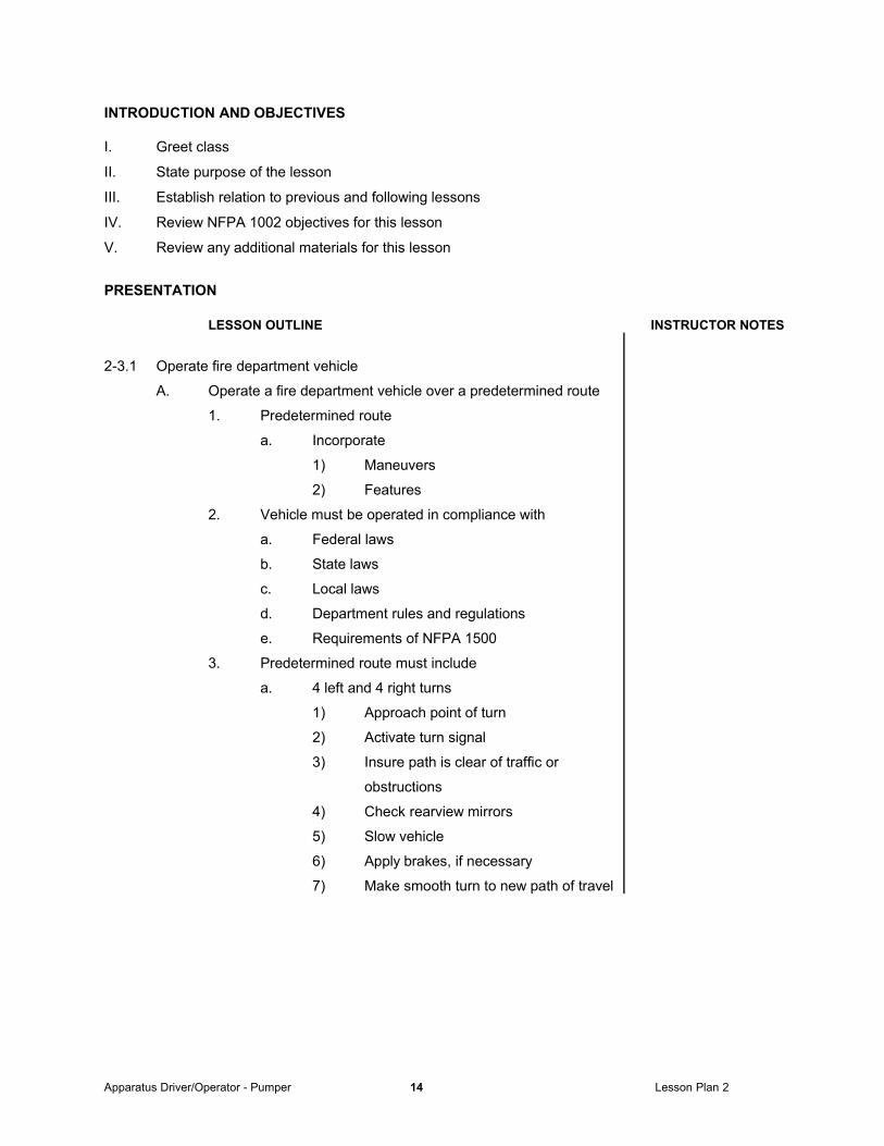
2-3.1 Operate fire department vehicle
A. Operate a fire department vehicle over a predetermined route
1. Predetermined route
a. Incorporate
1) Maneuvers
2) Features
2. Vehicle must be operated in compliance with
a. Federal laws
b. State laws
c. Local laws
d. Department rules and regulations
e. Requirements of NFPA 1500
3. Predetermined route must include
a. 4 left and 4 right turns
1) Approach point of turn
2) Activate turn signal
3) Insure path is clear of traffic or
obstructions
4) Check rearview mirrors
5) Slow vehicle
6) Apply brakes, if necessary
7) Make smooth turn to new path of travel
Apparatus Driver/Operator - Pumper 14 Lesson Plan 2
Page 15
LESSON OUTLINE INSTRUCTOR NOTES
b. Straight section of urban business street
1) Drive at posted speed limit or
drive based on conditions
3) Stay in correct lane
4) Move eyes to check
a) ahead
b) side streets and roads
c) other traffic
d) rear view mirrors
e) observe all traffic laws
c. 2 lane rural road
1) Drive at posted speed limit or
drive based on conditions
2) Stay in correct lane
3) Move eyes to check
a) ahead
b) side streets and roads
c) other traffic
d) rear view mirrors
4) Observe all traffic laws
d. Intersections
1) Going through
a) Approach with vehicle under
control
b) Observe cross streets/roads
c) Slow apparatus
d) Be prepared for controlled stop
e) Yield to traffic on the right
f) Proceed through intersection
when safe to do so
Apparatus Driver/Operator - Pumper 15 Lesson Plan 2
Page 16
LESSON OUTLINE INSTRUCTOR NOTES
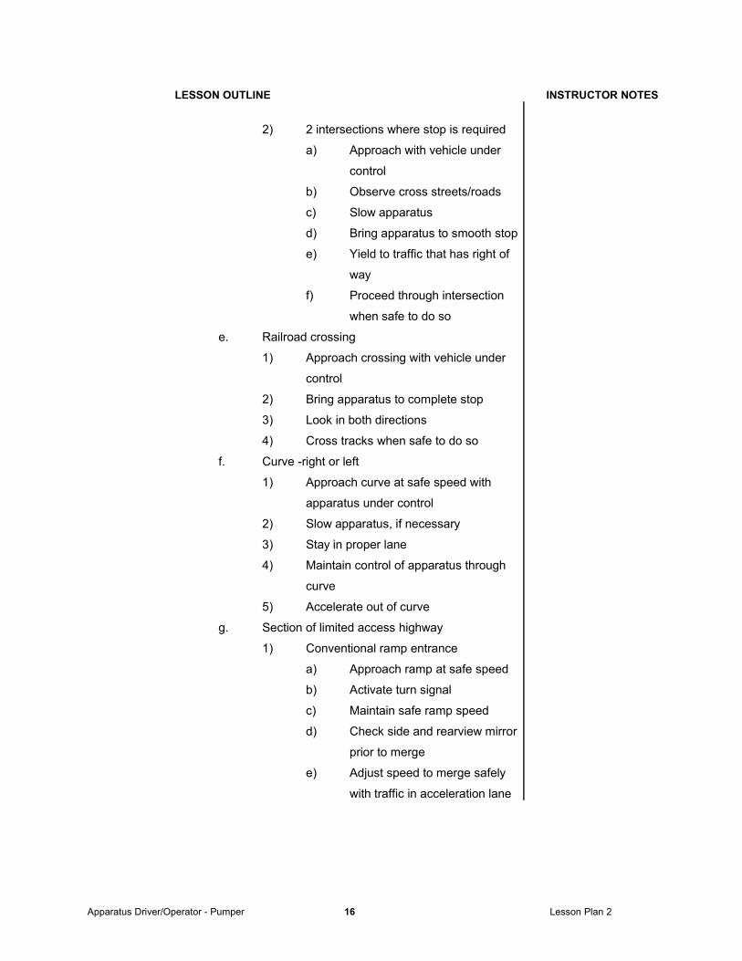
2) 2 intersections where stop is required
a) Approach with vehicle under
control
b) Observe cross streets/roads
c) Slow apparatus
d) Bring apparatus to smooth stop
e) Yield to traffic that has right of
way
f) Proceed through intersection
when safe to do so
e. Railroad crossing
1) Approach crossing with vehicle under
control
2) Bring apparatus to complete stop
3) Look in both directions
4) Cross tracks when safe to do so
f. Curve -right or left
1) Approach curve at safe speed with
apparatus under control
2) Slow apparatus, if necessary
3) Stay in proper lane
4) Maintain control of apparatus through
curve
5) Accelerate out of curve
g. Section of limited access highway
1) Conventional ramp entrance
a) Approach ramp at safe speed
b) Activate turn signal
c) Maintain safe ramp speed
d) Check side and rearview mirror
prior to merge
e) Adjust speed to merge safely
with traffic in acceleration lane
Apparatus Driver/Operator - Pumper 16 Lesson Plan 2
Page 17
LESSON OUTLINE INSTRUCTOR NOTES
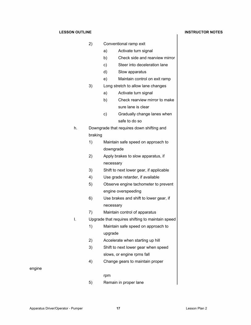
2) Conventional ramp exit
a) Activate turn signal
b) Check side and rearview mirror
c) Steer into deceleration lane
d) Slow apparatus
e) Maintain control on exit ramp
3) Long stretch to allow lane changes
a) Activate turn signal
b) Check rearview mirror to make
sure lane is clear
c) Gradually change lanes when
safe to do so
h. Downgrade that requires down shifting and
braking
1) Maintain safe speed on approach to
downgrade
2) Apply brakes to slow apparatus, if
necessary
3) Shift to next lower gear, if applicable
4) Use grade retarder, if available
5) Observe engine tachometer to prevent
engine overspeeding
6) Use brakes and shift to lower gear, if
necessary
7) Maintain control of apparatus
I. Upgrade that requires shifting to maintain speed
1) Maintain safe speed on approach to
upgrade
2) Accelerate when starting up hill
3) Shift to next lower gear when speed
slows, or engine rpms fall
4) Change gears to maintain proper
engine
rpm
5) Remain in proper lane
Apparatus Driver/Operator - Pumper 17 Lesson Plan 2
Page 18
LESSON OUTLINE INSTRUCTOR NOTES
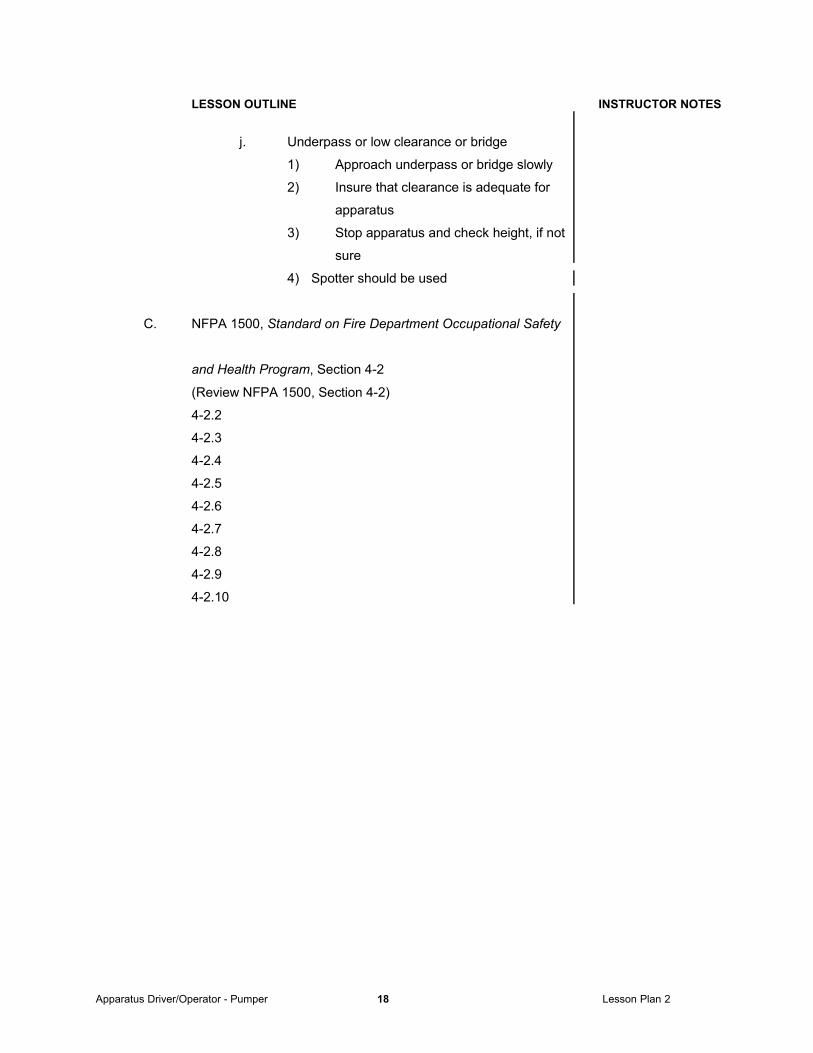
j. Underpass or low clearance or bridge
1) Approach underpass or bridge slowly
2) Insure that clearance is adequate for
apparatus
3) Stop apparatus and check height, if not
sure
4) Spotter should be used
C. NFPA 1500, Standard on Fire Department Occupational Safety
and Health Program, Section 4-2
(Review NFPA 1500, Section 4-2)
4-2.2
4-2.3
4-2.4
4-2.5
4-2.6
4-2.7
4-2.8
4-2.9
4-2.10
Apparatus Driver/Operator - Pumper 18 Lesson Plan 2
Page 19
LESSON OUTLINE INSTRUCTOR NOTES
2-3.1.1 Prerequisite Knowledge
A. Effect on vehicle control
1. Braking reaction time
a. Speed directly affects time required to stop
b. Driver should know stopping distances for
specific apparatus
1) Total stopping distance: Sum of
driver/operator reaction distance and vehicle
braking distance
2) Reaction distance: distance traveled
` while driver transfers foot from accelerator to
brake pedal after perceiving need to stop
3) Braking distance: distance vehicle
travels from time brakes are applied until it
comes to a complete stop
2. Load (weight) factors
a. Loads must be considered by all drivers
b. Laws of physics
1) When vehicle undergoes change in
velocity of direction - transfer takes
place relative to change
c. Position of load has effect on vehicle
1) The lower the load the easier to
control on turns
2) The higher the load the greater the
potential for skidding or rollover
3) Avoid high speed turns
4) Steer smoothly to avoid abrupt changes
5) Be extremely careful on slopes and hills
Apparatus Driver/Operator - Pumper 19 Lesson Plan 2
Page 20
LESSON OUTLINE INSTRUCTOR NOTES
3. General steering reactions
A. Be alert to situations in order to prevent rapid
steering movements and loss of control
B. Adjust speed for condition to maintain control
while maneuvering the vehicle
C. Keep both hands on the wheel at all times,
except when shifting or using other controls
D. Hands should be positioned at ten and
two o’clock
4. Speed
A. Adjust speed to compensate for conditions
1) Weather
2) Darkness
3) Traffic
4) Area
5. Centrifugal force
A. Force which acts or impels an object out from a
center of rotation.
B. Related factors
1) Speed of travel
2) Radius of curve
3) Road and tire conditions
4) Grade
5) Superelevation (banked, flat, crowned)
B. Applicable laws and regulations
1. Identify all applicable laws related to the operation of
emergency vehicles
a. Local
b. State
c. Federal
2. Identify all applicable rules and regulations of the
department
Apparatus Driver/Operator - Pumper 20 Lesson Plan 2
Page 21
LESSON OUTLINE INSTRUCTOR NOTES
3. General
a. Emergency vehicle operators are subject to
all traffic regulations unless a specific
exemption is made. The exemption(s) would
apply to emergency conditions only.
b. Legal decisions have held that driver/operators
who do not obey state, local, or department
regulations can be subject to criminal and civil
prosecution if the apparatus is involved in an
accident.
c. If the driver/operator is negligent and is
involved in an accident, both the driver/operator
and the department may be held responsible
d. Follow all laws regarding direction of travel,
direction of turns, and parking unless under
emergency conditions
e. Regardless of conditions - stop for school buses
with flashing lights
f. Obey all traffic laws and signals when returning
to quarters and non emergency travel.
2-3.1.2 Prerequisite Skills
A. Safe vehicle operation
1. Emergency and non-emergency defensive driving
a. Defensive driver
1) Makes allowances for
a) Own deficiencies
b) Lack of skill and knowledge of
others
2) Recognizes there is no control over
a) Unpredictable actions of others
b) Weather
3) Concedes right-of-way
4) Makes concessions to avoid collisions
5) Looks ahead and watches situations
develop
Apparatus Driver/Operator - Pumper 21 Lesson Plan 2
Page 22
LESSON OUTLINE INSTRUCTOR NOTES
b. Defensive driving factors
1) Proper attitude
a) Remain calm and drive in a
safe manner
b) Reckless driving is never
acceptable
c) Aggressive attitudes are a
menace to other vehicles,
pedestrians, and other fire
fighters on the apparatus
2) Anticipation of other drivers actions
a) Other drivers may panic at
sound of siren
b) Some ignore warning signals
c) Never assume other driver
will react in a rational manner
d) Always expect the unexpected
3) Focus fixation
a) Tendency to steer towards a
spot where attention is focused
b) Don’t focus on distractions
4) Visual lead time
a) Aim high in steering - get the
the big picture
b) Allows driver/operator to
become more aware of
conditions that may require
slowing or stopping
2. Safe driving during adverse weather
a. Slippery road surfaces
1) Increase stopping distances 3-15 times
more than normal
2) Try brakes in area free of traffic
3) If apparatus skids - release brakes
immediately
Apparatus Driver/Operator - Pumper 22 Lesson Plan 2
Page 23
LESSON OUTLINE INSTRUCTOR NOTES
4) Adjust speed to road and weather
conditions so that apparatus can be
stopped and maneuvered safely
b. Vehicle skids
1) Caused by:
a) Driving too fast
b) Failing to appreciate weight
shifts
c) Failing to anticipate obstacles
2) If apparatus goes into skid
a) Release brakes immediately
b) Steer in the direction of skid
c. Snow and ice
1) Snow tires and chains will
a) reduce stopping distance
b) Increase grip for starting
c) Increase hill climbing ability
2) Still necessary to maintain lower
speeds even with chains
3) Pump brakes gently on snow and ice
stopping distance
d. Fog
1) Visibility is at its worst in fog
2) Drive slowly using low beams
3) Avoid sudden stops by tapping on brake
pedal
4) Never assume a clear road except for
distance that you can actually see
B. Operate passenger restraining devices
1. Fasten seat belts
2. Make sure that all personnel are seated and belted
before moving apparatus
Apparatus Driver/Operator - Pumper 23 Lesson Plan 2
Page 24
LESSON OUTLINE INSTRUCTOR NOTES
2-3.2 Use automotive gauges and controls
A. Monitor gauges while operating the pumper
B. All applicable controls will be used during the performance of
the driving and operations functions required by this standard
2-3.2.1 Prerequisite Knowledge
A. Identification and operation of automotive gauges and proper
operation limits
1. Gauges are required to ensure proper operation of
engine and components and to warn of malfunctions
when gauges do not show normal operating ranges
2. Necessary when under way and when operating on the
fire ground
3. Some gauges are duplicated
a. Dashboard
b. Pump panel
4. Speedometer
a. Shows vehicle speed
5. Odometer
a. Shows miles traveled
6. Tachometer
a. Measures engine RPM (revolutions per minute)
b. Provides the driver/operator with information
on how to operate the vehicle efficiently without
harming the engine
c. Provides the driver/operator with information on
engine operation when pumping
d. Provides an indication of safe operating limits of
the engine
1) Consult technical manuals for proper
operating range
Apparatus Driver/Operator - Pumper 24 Lesson Plan 2
Page 25
LESSON OUTLINE INSTRUCTOR NOTES
7. Oil pressure gauge
a. Measures oil pressure
b. Indicates that oil is being supplied to the engine
at the proper pressure
c. Normal operating pressures are specified in
operations and maintenance manuals
d. Significant deviations from normal pressures
is an indication of a problem
e. Consult technical manuals for proper operating
range
8. Ammeter
a. Measures and shows the amount of current
drawn from the battery to operate electrical
equipment, or the amount of current being
supplied to the battery for charging
b. Consult technical manuals for proper operating
range
9. Voltmeter
a. Indicates battery conditions - low or high
b. Provides a relative indications of battery
condition by showing the amount of drop in
voltage that is measured when some of the
more demanding electrical accessories are
used.
c. Indicates the top voltage available when the
battery is fully charged
d. Consult technical manuals for proper operating
range
10. Air pressure gauge
a. Indicates air pressure available to operate air
brakes
b. Consult technical manuals for proper operating
range
Apparatus Driver/Operator - Pumper 25 Lesson Plan 2
Page 26
LESSON OUTLINE INSTRUCTOR NOTES
11. Water temperature gauge
a. Indicates temperature of engine coolant
b. Provides an indication of when the engine is
overheating
c. Consult technical manuals for proper operating
range
12. Fuel gauge
a. Indicates the level of fuel in the tank
13. Transmission oil temperature, if applicable
a. Shows temperate of transmission oil
b. Consult technical manuals for proper operating
range2-3.2.2 Prerequisite Skills
A. Operate vehicle controls
1. Set parking brake
2. Place transmission gear selector in neutral
3. Turn master switch on
4. Turn on ignition switch
5. Engage starter switch
6. After start-up observe engine gauges and warning lights
for proper readings
1) Run engine at 800 to 1,000 rpm to obtain proper
operating temperatures and gauge readings
7. Turn on all necessary lights, communications
equipment, and warning equipment
8. Select proper gear range
9. Move vehicle forward
10. Come to a complete stop
11. Shift into reverse
12. Come to a complete stop
13. Place transmission selector in neutral
14. Apply parking brake
Apparatus Driver/Operator - Pumper 26 Lesson Plan 2
Page 27
LESSON OUTLINE INSTRUCTOR NOTES
15. Allow engine to idle for at least 2 minutes before shut
down
a. Immediate shutdown results in engine
temperature increase
b. May result in damage to heads, exhaust
manifolds, and turbocharger
c. Engine temperature should stabilize before
shutdown
16. Reduce engine speed to low idle
17. Shut of all lights and other equipment
18. Turn ignition switch off
19. Place electrical master switch in the off position
2-3.3 Back a fire department vehicle from a roadway
A. Into a restricted space on right and left side
1. Measures driver/operators ability to drive past a space
and to back the apparatus into the space without having
to stop and pull forward
2. Spotter must be used
3. Restricted space 12 ft in width (Unless vehicle is
exceptionally wide, variance must requested.)
4. Exercise requires a 90 degree right and left hand turns
from roadway
5. Vehicle must be parked
a. Without having to stop and pull forward
b. Without striking obstructions
6. Steps
a. Driver/operator should drive forward and pass
the dock on the left
b. Stop the apparatus
c. Back the apparatus into the dock
d. Repeat the steps by driving forward with the
dock on the right
Apparatus Driver/Operator - Pumper 27 Lesson Plan 2
Page 28
LESSON OUTLINE INSTRUCTOR NOTES
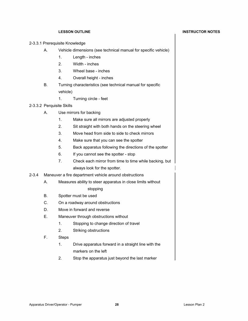
2-3.3.1 Prerequisite Knowledge
A. Vehicle dimensions (see technical manual for specific vehicle)
1. Length - inches
2. Width - inches
3. Wheel base - inches
4. Overall height - inches
B. Turning characteristics (see technical manual for specific
vehicle)
1. Turning circle - feet
2-3.3.2 Perquisite Skills
A. Use mirrors for backing
1. Make sure all mirrors are adjusted properly
2. Sit straight with both hands on the steering wheel
3. Move head from side to side to check mirrors
4. Make sure that you can see the spotter
5. Back apparatus following the directions of the spotter
6. If you cannot see the spotter - stop
7. Check each mirror from time to time while backing, but
always look for the spotter.
2-3.4 Maneuver a fire department vehicle around obstructions
A. Measures ability to steer apparatus in close limits without
stopping
B. Spotter must be used
C. On a roadway around obstructions
D. Move in forward and reverse
E. Maneuver through obstructions without
1. Stopping to change direction of travel
2. Striking obstructions
F. Steps
1. Drive apparatus forward in a straight line with the
markers on the left
2. Stop the apparatus just beyond the last marker
Apparatus Driver/Operator - Pumper 28 Lesson Plan 2
Page 29
LESSON OUTLINE INSTRUCTOR NOTES
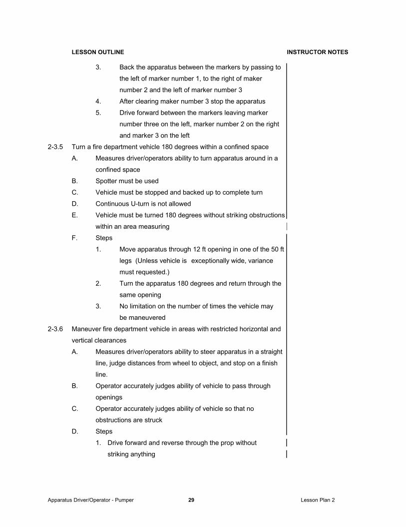
3. Back the apparatus between the markers by passing to
the left of marker number 1, to the right of maker
number 2 and the left of marker number 3
4. After clearing maker number 3 stop the apparatus
5. Drive forward between the markers leaving marker
number three on the left, marker number 2 on the right
and marker 3 on the left
2-3.5 Turn a fire department vehicle 180 degrees within a confined space
A. Measures driver/operators ability to turn apparatus around in a
confined space
B. Spotter must be used
C. Vehicle must be stopped and backed up to complete turn
D. Continuous U-turn is not allowed
E. Vehicle must be turned 180 degrees without striking obstructions
within an area measuring
F. Steps
1. Move apparatus through 12 ft opening in one of the 50 ft
legs (Unless vehicle is exceptionally wide, variance
must requested.)
2. Turn the apparatus 180 degrees and return through the
same opening
3. No limitation on the number of times the vehicle may
be maneuvered
2-3.6 Maneuver fire department vehicle in areas with restricted horizontal and
vertical clearances
A. Measures driver/operators ability to steer apparatus in a straight
line, judge distances from wheel to object, and stop on a finish
line.
B. Operator accurately judges ability of vehicle to pass through
openings
C. Operator accurately judges ability of vehicle so that no
obstructions are struck
D. Steps
1. Drive forward and reverse through the prop without
striking anything
Apparatus Driver/Operator - Pumper 29 Lesson Plan 2
Page 30
LESSON OUTLINE INSTRUCTOR NOTES
2-3.8 Operate systems and equipment
A. Operate in accordance with
1. Manufacturers instructions and specifications
2. Department policies and procedures
3. Technical order
B. Systems
1. Set relief valve
a. Pump in operation
b. All lines flowing at desired flow rate
c. Set relief valve at desired relief pressure
d. Check to make sure discharge pressure is
maintained
2. Set pressure governor
a. Set governor for desired discharge pressure
b. Check to make sure discharge pressure is
maintained
C. Equipment
1. Operate each piece of equipment that is carried on the
vehicle
2-3.6.1 Prerequisite Skills
A. Judging vehicle clearances
1. Skill development
a. Practice judging distances while driving and
maneuvering at slow speeds.
b. Stop periodically get out of vehicle and look at
actual distances
c. Perform maneuvers that will develop skill at
judging distance to the:
1) Front
2) Back
3) Height
4) Width/sides
d. Use spotter
Apparatus Driver/Operator - Pumper 30 Lesson Plan 2
Page 31
REVIEW
I. Discuss key lesson points.
II. Ask questions on the material covered.
III. Review material that may be unclear.
IV. Administer test or quiz.
V. Critique test or quiz.
SUMMARY
I. Summarize what has been covered.
II. Relate what has been covered to the next lesson.
Apparatus Driver/Operator - Pumper 31 Lesson Plan 3
Page 32
DOD FIRE SERVICE CERTIFICATION SYSTEM
LESSON PLAN 3
Personnel Classification: Apparatus/Driver Operator - Pumper
Subject: Pumper - General
NFPA 1002 Objectives
3-1.23-1.33-1.43-1.5
Training Materials/Equipment:
Fully equipped and operational pumper.
References:
IFSTA, Fire Department Pumping Apparatus, 7th Edition, 1989, Fire Protection Publications, Oklahoma State University.
IFSTA, Fire Stream Practices, 7th Edition, 1989, Fire Protection Publications, Oklahoma State University.
IFSTA, Water Supplies for Fire Protection, 4th Edition, 1988, Fire Protection Publications, Oklahoma State University.
NFPA 1002: Fire Vehicle Operator Professional Qualifications, 1993 National Fire Protection Association, Quincy, Massachusetts
NFPA 1500: Standard on Fire Department Occupational Safety and Health Programs, 1992 National Fire Protection Association, Quincy, Massachusetts
Additional Information:
IFSTA Firefighter Videotape Series - Fire Pump Operation and Maintenance, Fire Protection Publications, Oklahoma State University
• Review lesson outline to ensure understanding of contents and procedures.
• Review references for lesson.
• Use additional references and your knowledge to enrich lesson outline.
• Ensure that all equipment needed, including any audio-visual equipment, is available.
• Review lesson at end of session to ensure student understanding.
• Ensure that the topics and objectives of the lesson have been adequately covered
.
Apparatus Driver/Operator - Pumper 32 Lesson Plan 3
Page 33
INTRODUCTION AND OBJECTIVES
I. Greet class
II. State purpose of the lesson
III. Establish relation to previous and following lessons
IV. Review NFPA 1002 objectives for this lesson
V. Review any additional materials for this lesson
PRESENTATION
LESSON OUTLINE INSTRUCTOR NOTES
3-1.2 Perform routine tests, inspections and service functions
See Lesson Plan 1, 2-2.1
3-1.3 Practical driving exercises
See Lesson Plan 2, 2-3.3 through 2-3.6
3-1.4 Position a fire department pumper
A. At a fire hydrant
1. Hard suction hose
a. Consider length of hard suction hose
b. Hose may be connected either to hydrant or
pumper first
c. Position pumper to make final connection
3. Soft suction hose
a. Consider length of soft suction hose
b. Hose may be connected either to hydrant or
pumper first
c. Position pumper to make final connection
d. Hose must not have kinks or sharp bends
B. At a static water supply source
1. Consider lift and horizontal distance to water source
2. Consider stability of ground to support pumper
a. Initially
b. During a long period of pumping
3. Connect hard suction to intake
3-1.5 Operate a fire department pumper over a predetermined route
Covered in Lesson Plan 2
Apparatus Driver/Operator - Pumper 33 Lesson Plan 3
Page 34
REVIEW
I. Discuss key lesson points.
II. Ask questions on the material covered.
III. Review material that may be unclear.
IV. Administer test or quiz.
V. Critique test or quiz.
SUMMARY
I. Summarize what has been covered.
II. Relate what has been covered to the next lesson.
Apparatus Driver/Operator - Pumper 34 Lesson Plan 4
Page 35
DOD FIRE SERVICE CERTIFICATION SYSTEM
LESSON PLAN 4
Personnel Classification: Apparatus/Driver Operator - Pumper
Subject: Water Supply
NFPA 1002 Objectives
3-2.13-2.1.1
Training Materials/Equipment:
Classroom, chalkboard, references, etc.
References:
IFSTA, Fire Department Pumping Apparatus, 7th Edition, 1989, Fire Protection Publications, Oklahoma State University.
IFSTA, Fire Stream Practices, 7th Edition, 1989, Fire Protection Publications, Oklahoma State University.
IFSTA, Water Supplies for Fire Protection, 4th Edition, 1988, Fire Protection Publications, Oklahoma State University.
NFPA 1002: Fire Vehicle Operator Professional Qualifications, 1993 National Fire Protection Association, Quincy, Massachusetts
NFPA 1500: Standard on Fire Department Occupational Safety and Health Programs, 1992 National Fire Protection Association, Quincy, Massachusetts
NFPA 291: Recommended Practice for Fire Flow Testing and Marking of Hydrants, 1995National Fire Protection Association, Quincy, Massachusetts
Additional Information:
IFSTA Firefighter Videotape Series - Fire Pump Operation and Maintenance, Fire Protection Publications, Oklahoma State University
IFSTA Firefighter Videotape Series - Developing Fire Flow/Hydraulics, Fire Protection Publications, Oklahoma State University.
Apparatus Driver/Operator - Pumper 35 Lesson Plan 4
Page 36
Instructor Tasks
• Review lesson outline to ensure understanding of contents and procedures.
• Review references for lesson.
• Use additional references and your knowledge to enrich lesson outline.
• Select and prepare any additional audio-visual aids that may assist in the presentation of the lesson.
• Ensure that all equipment needed, including any audio-visual equipment, is available.
• Review lesson at end of session to ensure student understanding.
• Ensure that the topics and objectives of the lesson have been adequately covered
.
Apparatus Driver/Operator - Pumper 36 Lesson Plan 4
Page 37
INTRODUCTION AND OBJECTIVES
I. Greet class
II. State purpose of the lesson
III. Establish relation to previous and following lessons
IV. Review NFPA 1002 objectives for this lesson
V. Review any additional materials for this lesson
PRESENTATION
LESSON OUTLINE INSTRUCTOR NOTES
3-2.1 Estimate fire flow based on the following:
A. Location
1. Building, structure, vehicle, vessel (tank, container, etc.)
a. Amount of fire
b. Size (building, vessel)
c. Construction
d. Contents
2. Exposures
3. Rule of thumb formula for estimating initial fire flow
a. Length x Width of Building / 3 = gpm
b. Example
1) 60 ft x 30 ft = 1800/3 = 600 gpm
B. Alternative sources of water
1. Fire hydrants
2. Static sources
3. Tankers
Apparatus Driver/Operator - Pumper 37 Lesson Plan 4
Page 38
LESSON OUTLINE INSTRUCTOR NOTES
3-2.1.1 Prerequisite Knowledge
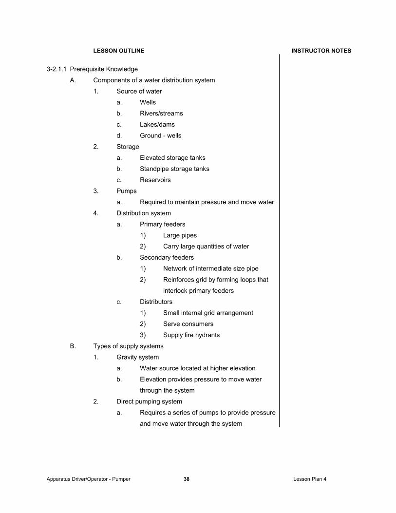
A. Components of a water distribution system
1. Source of water
a. Wells
b. Rivers/streams
c. Lakes/dams
d. Ground - wells
2. Storage
a. Elevated storage tanks
b. Standpipe storage tanks
c. Reservoirs
3. Pumps
a. Required to maintain pressure and move water
4. Distribution system
a. Primary feeders
1) Large pipes
2) Carry large quantities of water
b. Secondary feeders
1) Network of intermediate size pipe
2) Reinforces grid by forming loops that
interlock primary feeders
c. Distributors
1) Small internal grid arrangement
2) Serve consumers
3) Supply fire hydrants
B. Types of supply systems
1. Gravity system
a. Water source located at higher elevation
b. Elevation provides pressure to move water
through the system
2. Direct pumping system
a. Requires a series of pumps to provide pressure
and move water through the system
Apparatus Driver/Operator - Pumper 38 Lesson Plan 4
Page 39
LESSON OUTLINE INSTRUCTOR NOTES
3. Combination
a. Gravity and pumps are used to supply the
system
B. Problems related to small diameter and dead-end mains
1. Small diameter pipe
a. 4 inch and smaller pipe do not have the capacity
to supply fire flows of 500, 750 and 1,000 gpm
b. 6 inch has limited capacity for short distances
c. 8 inch preferred to supply fire hydrants
2. Dead end mains
a. Long lengths of small diameter pipe cannot
supply adequate fire flows to hydrants
b. Maximum length of dead end supply to hydrants
at 1,000 gpm
1) 4 inch 50 feet
2) 6 inch 380
3) 8 inch 1,550
C. Low pressure
1. May result in inadequate supply
2. Some systems may supply large quantities at
low pressures
3. Most reliable way to know is to conduct flow tests
to determine available water at various locations
D. Private water supply systems
1. May or may not be reliable
2. May have limited capacity
3. May have limited duration
4. Hose threads may not be compatible
5. Determine strengths and weaknesses through
pre fire planning
Apparatus Driver/Operator - Pumper 39 Lesson Plan 4
Page 40
LESSON OUTLINE INSTRUCTOR NOTES
E. Hydrant coding systems
1. Some systems may be coded using NFPA 291,
Standard on Fire Flow Testing and Marking of
Hydrants
2. Color Coding system
a. 1,500 gpm or greater light blue
b. 1,000 gpm to 1,499 gpm green
c. 500 gpm to 999 gpm orange
d. less than 500 gpm red
e. Caps and bonnets should be painted
f. Periodic flow tests be conducted so that coding
is accurate - no specific times for testing
g. Caution should be used with coding system
1) During peak demand periods quantity
may be less than indicated
F. Reliability of static water sources
1. May or may not be water due to season or demand
2. Water level may vary by season or demand
3. May not be accessible when level is low
4. If primary source, check frequently
Apparatus Driver/Operator - Pumper 40 Lesson Plan 4
Page 41
REVIEW
I. Discuss key lesson points.
II. Ask questions on the material covered.
III. Review material that may be unclear.
IV. Administer test or quiz.
V. Critique test or quiz.
SUMMARY
I. Summarize what has been covered.
II. Relate what has been covered to the next lesson.
Apparatus Driver/Operator - Pumper 41 Lesson Plan 5
Page 42
DOD FIRE SERVICE CERTIFICATION SYSTEM
LESSON PLAN 5
Personnel Classification: Apparatus/Driver Operator - Pumper
Subject: Sprinklers and Standpipes
NFPA 1002 Objectives
3-3.13-3.1.1
Training Materials/Equipment:
Fully equipped fire department pumper and training facility equipped with sprinkler or standpipe system
References:
IFSTA, Fire Department Pumping Apparatus, 7th Edition, 1989, Fire Protection Publications, Oklahoma State University.
IFSTA, Fire Stream Practices, 7th Edition, 1989, Fire Protection Publications, Oklahoma State University.
IFSTA, Water Supplies for Fire Protection, 4th Edition, 1988, Fire Protection Publications, Oklahoma State University.
NFPA 1002: Fire Vehicle Operator Professional Qualifications, 1993 National Fire Protection Association, Quincy, Massachusetts
NFPA 1500: Standard on Fire Department Occupational Safety and Health Programs, 1992 National Fire Protection Association, Quincy, Massachusetts
Additional Information:
IFSTA Firefighter Videotape Series - Fire Pump Operation and Maintenance, Fire Protection Publications, Oklahoma State University
• Review lesson outline to ensure understanding of contents and procedures.
• Review references for lesson.
• Use additional references and your knowledge to enrich lesson outline.
• Ensure that all equipment needed, including any audio-visual equipment, is available.
• Review lesson at end of session to ensure student understanding.
• Ensure that the topics and objectives of the lesson have been adequately covered
.
Apparatus Driver/Operator - Pumper 42 Lesson Plan 5
Page 43
INTRODUCTION AND OBJECTIVES
I. Greet class
II. State purpose of the lesson
III. Establish relation to previous and following lessons
IV. Review NFPA 1002 objectives for this lesson
V. Review any additional materials for this lesson
PRESENTATION
LESSON OUTLINE INSTRUCTOR NOTES
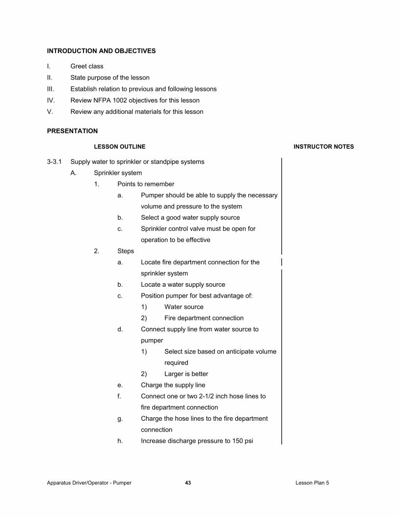
3-3.1 Supply water to sprinkler or standpipe systems
A. Sprinkler system
1. Points to remember
a. Pumper should be able to supply the necessary
volume and pressure to the system
b. Select a good water supply source
c. Sprinkler control valve must be open for
operation to be effective
2. Steps
a. Locate fire department connection for the
sprinkler system
b. Locate a water supply source
c. Position pumper for best advantage of:
1) Water source
2) Fire department connection
d. Connect supply line from water source to
pumper
1) Select size based on anticipate volume
required
2) Larger is better
e. Charge the supply line
f. Connect one or two 2-1/2 inch hose lines to
fire department connection
g. Charge the hose lines to the fire department
connection
h. Increase discharge pressure to 150 psi
Apparatus Driver/Operator - Pumper 43 Lesson Plan 5
Page 44
LESSON OUTLINE INSTRUCTOR NOTES
i. Monitor and adjust discharge pressure when
conditions change.
j. Shut down only when directed by Command.
B. Standpipe system
1. Points to remember
a. Pumper should be able to supply the necessary
volume and pressure to the system
b. Select a good water supply source
c. System may be wet or dry
d. Dry system will have to be filled when first
connected
2. Steps
a. Locate fire department connection for the
standpipe system
b. Locate a water supply source
c. Position pumper to best advantage
1) Water source
2) Near fire department connection
d. Connect supply line from water source to
pumper
1) Select size based on anticipate volume
required
2) Larger is better
e. Charge the supply line
f. Connect one or two 2-1/2 inch hose lines to
fire department connection
g. Charge the hose lines to the fire department
connection
h. Increase discharge pressure to 150 psi
I. Adjust discharge pressure based on the
following:
1) Height of fire floor
a) Add 5 psi for each floor
b) Elevation loss is .5 psi per foot
c) Average height of floor = 10 ft
Apparatus Driver/Operator - Pumper 44 Lesson Plan 5
Page 45
LESSON OUTLINE INSTRUCTOR NOTES
2) Friction loss in standpipe system
a) Add 25 psi
3) Friction loss for standpipe hose line,
based on size and length
4) Communication with crew on fire floor
I. Monitor and adjust discharge pressure when
conditions change.
j. Shut down only when directed by Command
3-3.1.1 Prerequisite Knowledge
A. Pump discharge pressure
1. Sprinkler systems
a. Calculate engine discharge pressure to provide
150 psi at the sprinkler connection
2. Standpipe systems
a. Calculate engine discharge pressure based on
the following:
1) Height of fire floor
a) Add 5 psi per floor
2) Number and size of hose lines used on
fire floor
a) Calculate friction loss based on
diameter, length and desired
nozzle pressure
3) Friction loss in standpipe system
a) Use 25 psi for standpipe system
4) Total all friction loss figures to
determine pump pressure
B. Hose layouts
1. Will vary with each type of occupancy and system
2. Small sprinkler and standpipe systems have only one
hose connection
3. Large systems may have more than one hose
connection
Apparatus Driver/Operator - Pumper 45 Lesson Plan 5
Page 46
LESSON OUTLINE INSTRUCTOR NOTES
4. May be forward or reverse lay depending upon:
1) Location of sprinkler or standpipe connection
a) Some connections are located on
building
b) Some connections are located a
distance from the protected building
2) Location of water source
5. Layout should be made based on:
1) Anticipated volume (gpm) required
2) Pre fire plan estimates
C. Location of fire department connection
D. Operating principles of sprinkler systems as defined in:
1. NFPA 13, Standard for the Installation of Sprinkler
Systems
2. NFPA 13D, Standard for the Installation of Sprinkler
Systems in One and Two Family Dwellings and Mobile
Homes
3. NFPA 13R, Standard for the Installation of Sprinkler
Systems in Residential Occupancies Up to and Including
Four Stories in Height
E. Fire department operations in sprinklered occupancies as
defined in:
1. NFPA 13E, Recommendations for Fire Department
Operations in Properties Protected by Sprinkler and
Standpipe Systems.
F. Operating principles of standpipe systems as defined in:
1. NFPA 14, Standard for the Installation of Standpipes
and Hose Systems
Apparatus Driver/Operator - Pumper 46 Lesson Plan 5
Page 47
REVIEW
I. Discuss key lesson points.
II. Ask questions on the material covered.
III. Review material that may be unclear.
IV. Administer test or quiz.
V. Critique test or quiz.
SUMMARY
I. Summarize what has been covered.
II. Relate what has been covered to the next lesson.
Apparatus Driver/Operator - Pumper 47 Lesson Plan 6
Page 48
DOD FIRE SERVICE CERTIFICATION SYSTEM
LESSON PLAN 6
Personnel Classification: Apparatus/Driver Operator - Pumper
Subject: Operations
NFPA 1002 Objectives
3-4.13-4.1.13-4.1.23-4.23-4.33-4.4
Training Materials/Equipment:
Fully equipped pumper, pressurized water source, static water source, foam concentrate, foam eductors and nozzle, chalkboard, or overhead projector
References:
IFSTA, Fire Department Pumping Apparatus, 7th Edition, 1989, Fire Protection Publications, Oklahoma State University.
IFSTA, Fire Stream Practices, 7th Edition, 1989, Fire Protection Publications, Oklahoma State University.
IFSTA, Water Supplies for Fire Protection, 4th Edition, 1988, Fire Protection Publications, Oklahoma State University.
NFPA 1002: Fire Vehicle Operator Professional Qualifications, 1993 National Fire Protection Association, Quincy, Massachusetts
NFPA 1500: Standard on Fire Department Occupational Safety and Health Programs, 1992 National Fire Protection Association, Quincy, Massachusetts
Additional Information:
IFSTA Firefighter Videotape Series - Fire Pump Operation and Maintenance, Fire Protection Publications, Oklahoma State University
Apparatus Driver/Operator - Pumper 48 Lesson Plan 6
Page 49
Instructor Tasks
• Review lesson outline to ensure understanding of contents and procedures.
• Review references for lesson.
• Use additional references and your knowledge to enrich lesson outline.
• Select and prepare any additional audio-visual aids that may assist in the presentation of the lesson.
• Ensure that all equipment needed, including any audio-visual equipment, is available.
• Review lesson at end of session to ensure student understanding.
• Ensure that the topics and objectives of the lesson have been adequately covered
.
Apparatus Driver/Operator - Pumper 49 Lesson Plan 6
Page 50
INTRODUCTION AND OBJECTIVES
I. Greet class
II. State purpose of the lesson
III. Establish relation to previous and following lessons
IV. Review NFPA 1002 objectives for this lesson
V. Review additional objectives for this lesson
PRESENTATION
LESSON OUTLINE INSTRUCTOR NOTES
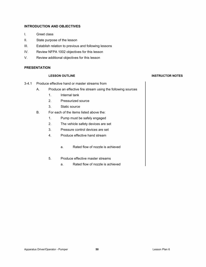
3-4.1 Produce effective hand or master streams from
A. Produce an effective fire stream using the following sources
1. Internal tank
2. Pressurized source
3. Static source
B. For each of the items listed above the:
1. Pump must be safely engaged
2. The vehicle safety devices are set
3. Pressure control devices are set
4. Produce effective hand stream
a. Rated flow of nozzle is achieved
5. Produce effective master streams
a. Rated flow of nozzle is achieved
Apparatus Driver/Operator - Pumper 50 Lesson Plan 6
Page 51
LESSON OUTLINE INSTRUCTOR NOTES
3-4.1.1 Prerequisite Knowledge
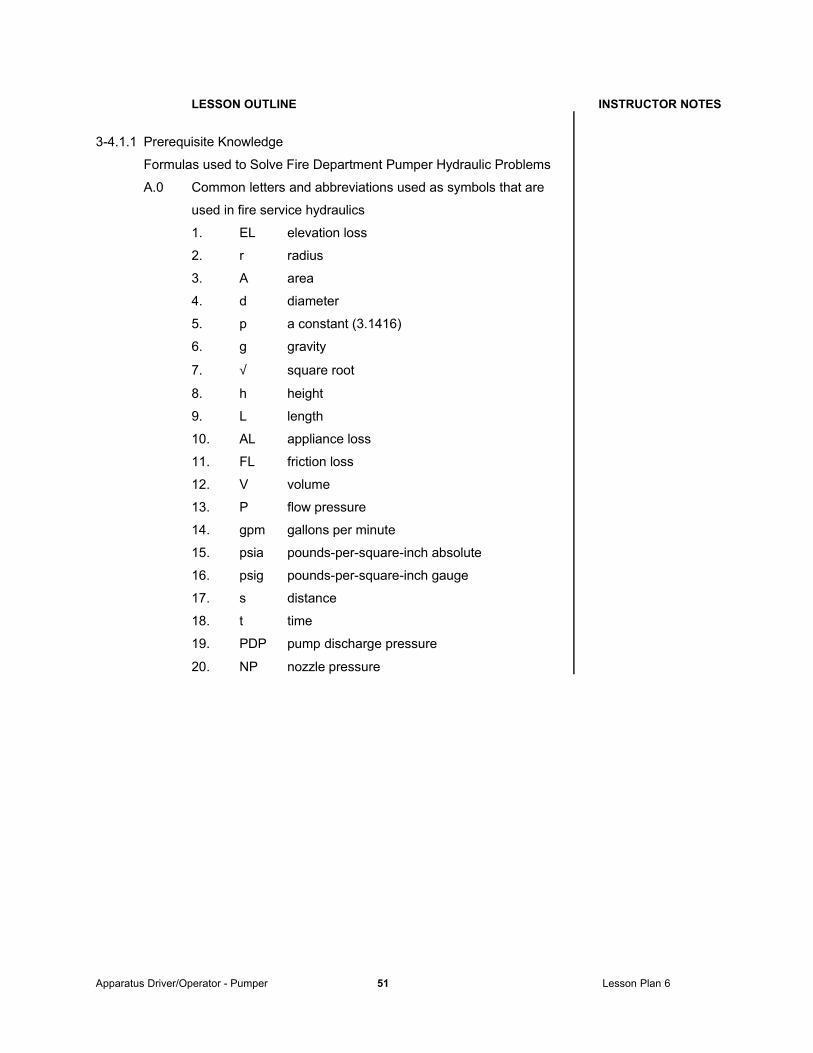
Formulas used to Solve Fire Department Pumper Hydraulic Problems
A.0 Common letters and abbreviations used as symbols that are
used in fire service hydraulics
1. EL elevation loss
2. r radius
3. A area
4. d diameter
5. p a constant (3.1416)
6. g gravity
7. √ square root
8. h height
9. L length
10. AL appliance loss
11. FL friction loss
12. V volume
13. P flow pressure
14. gpm gallons per minute
15. psia pounds-per-square-inch absolute
16. psig pounds-per-square-inch gauge
17. s distance
18. t time
19. PDP pump discharge pressure
20. NP nozzle pressure
Apparatus Driver/Operator - Pumper 51 Lesson Plan 6
Page 52
LESSON OUTLINE INSTRUCTOR NOTES
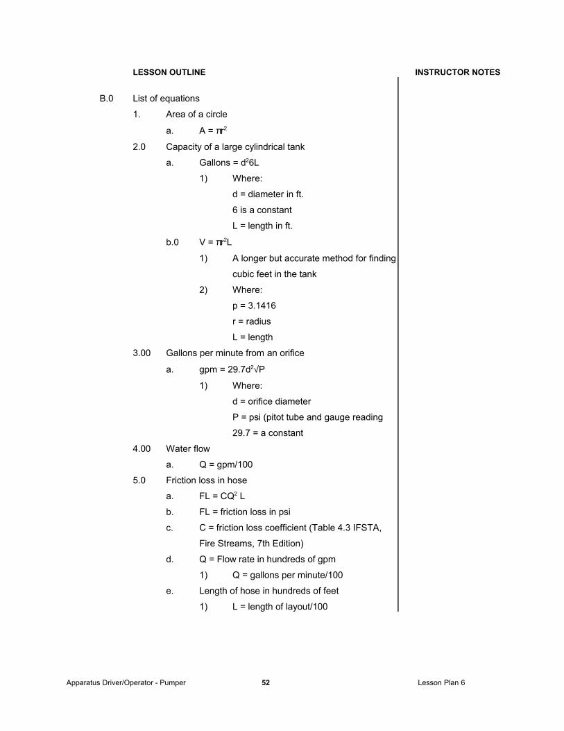
B.0 List of equations
1. Area of a circle
a. A = πr2
2.0 Capacity of a large cylindrical tank
a. Gallons = d26L
1) Where:
d = diameter in ft.
6 is a constant
L = length in ft.
b.0 V = πr2L
1) A longer but accurate method for finding
cubic feet in the tank
2) Where:
p = 3.1416
r = radius
L = length
3.00 Gallons per minute from an orifice
a. gpm = 29.7d2√P
1) Where:
d = orifice diameter
P = psi (pitot tube and gauge reading
29.7 = a constant
4.00 Water flow
a. Q = gpm/100
5.0 Friction loss in hose
a. FL = CQ2 L
b. FL = friction loss in psi
c. C = friction loss coefficient (Table 4.3 IFSTA,
Fire Streams, 7th Edition)
d. Q = Flow rate in hundreds of gpm
1) Q = gallons per minute/100
e. Length of hose in hundreds of feet
1) L = length of layout/100
Apparatus Driver/Operator - Pumper 52 Lesson Plan 6
Page 53
LESSON OUTLINE INSTRUCTOR NOTES
6.0 Nozzle reaction
a. NR = 0.0505Q√NP
1) NR = nozzle reaction
Q = flow (GPM)
NP = nozzle pressure; (psi at base of
nozzle)
0.0505 is a constant
8. Friction loss coefficients for single hose lines*
a. For use with the formula FL = CQ2L
b. Size/Type of hose Coefficient
1-1/2 inch 24
1-3/4 inch 15.5
2 inch 8
2-1/2 inch 2
3 inch 0.8
4 inch 0.2
5 inch 0.08
6 inch 0.05
*Table 4.3 IFSTA, Fire Streams, 7th Edition
9.0 Required pump discharge pressure
a. PDP = NP + FL
2) PDP = pump discharge
NP = nozzle pressure
FL = friction loss
10.00 PDP with back pressure and pressure "gain"
a. PDP = NP+FL+0.5(h)
1) h = ft. above or below the pump
0.05 is a constant
Apparatus Driver/Operator - Pumper 53 Lesson Plan 6
Page 54
LESSON OUTLINE INSTRUCTOR NOTES
C. Hydraulic calculations for friction loss
Find the nozzle or pump discharge pressures
1. Given
b. Length of hose = 400 ft.
c. Size of hose = 2-1/2 in.
d. Size of nozzle = 2-1/2 in.
e. Type of nozzle = variable gallonage fog nozzle
f. Gpm = 250
g. Nozzle pressure = 100 psi
7.0 Solution
a. Friction loss formula
1) FL = CQ2L
2) FL = 2 x 2.52 x 1
3) FL = 2 x 6.25 x 1
4) FL = 12.5 psi
5) FL = 12.5 psi / 100 feet
b.0 Formula for quantity based on the gpm flowing
through the nozzle
1) Quantity Q) = gpm 100
2) Q = 250 100
3) Q = 2.5
c.0 Multiply the friction loss (FL) per 100 feet by the
length of hose (HL) per 100 ft. to find total
friction loss for the hose
1) Total Friction Loss = FLxHL
2) Total Friction Loss = 12.5 x 4
3) Total Friction Loss = 50 psi
d.0 Pump discharge pressure equals friction loss
plus nozzle pressure
1) PDP = FL+NP
2) PDP = 50+100
3) PDP = 150
Apparatus Driver/Operator - Pumper 54 Lesson Plan 6
Page 55
LESSON OUTLINE INSTRUCTOR NOTES
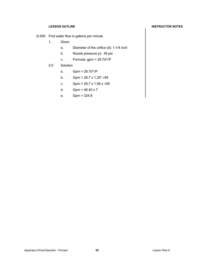
D.000 Find water flow in gallons per minute
1. Given
a. Diameter of the orifice (d): 1-1/4 inch
b. Nozzle pressure p): 49 psi
c. Formula: gpm = 29.7d2√P
2.0 Solution
a. Gpm = 29.7d2√P
b. Gpm = 29.7 x 1.252 √49
c. Gpm = 29.7 x 1.56 x √49
d. Gpm = 46.40 x 7
e. Gpm = 324.8
Apparatus Driver/Operator - Pumper 55 Lesson Plan 6
Page 56
LESSON OUTLINE INSTRUCTOR NOTES
E.00 Find friction loss in the supply and attack lines
1. Given
a. Length and size of lines = 300 ft. of 2-1/2 in.
supply line wyed into three 200 ft. of 1-1/2 in.
lines
b. Gpm flow = 100 gpm from each nozzle
c. Friction loss FL) in wye = 10 psi
d. Constant for 1-1/2 in. conversion = 13.5
e. Formulas needed
1) Q = gpm
100
2) FL = CQ2L
2.00 Solution
a. First find FL in the 1-1/2 inch line
1) Q = gpm 100
2) Q = 100 100
3) Q = 1
4) FL = CQ2L
5) FL = 24 x 1 x 2
6) FL = 48 psi / 200 feet
Apparatus Driver/Operator - Pumper 56 Lesson Plan 6
Page 57
LESSON OUTLINE INSTRUCTOR NOTES
b.0 Second, find the FL for the 2-1/2 inch line
1) Q = gpm 100
2) Q = 300 100
3) Line 1 = 100 gpm
Line 2 = 100 gpm
Line 3 = 100 gpm
Total flow = 300 gpm
4) Q = 3
3) FL = CQ2L
4) FL = 2 x 32 x 3
5) FL = 2 x 9 x 3
6) FL =54 psi / 300 feet
c.0 Total friction loss (TFL)
1) 48 psi - 1-1/2 inch
2) 54 psi - 2-1/2 inch
3) 102 psi total friction loss (FL)
d. Friction loss (FL) in wye = 10 psi if the flow is
over 350 gpm
F.000 Find friction loss in siamesed lines
1. Given
a. Size and length of hose: two 2-1/2 in. lines each
1,000 ft., into one 2-1/2 in. 100 ft. long
b. Gpm flow: 250
c. Nozzle type = variable gallonage fog nozzle
d. Formulas
1) Q = gpm 100
2) FL = CQ2L
Apparatus Driver/Operator - Pumper 57 Lesson Plan 6
Page 58
LESSON OUTLINE INSTRUCTOR NOTES
2.00 Solution
a. First, calculate the friction loss for the single line
1) Q = gpm 100
2) Q = 250 100
3) Q = 2.5
4) FL = CQ2L
5) FL = 2 x 2.52 x 1
6) FL = 2 x 6.25 x 1
7) FL = 12.5 psi / 100 feet
b. Calculate the friction loss of the two 2 - 1/2 lines
1) FL = CQ2L
2) FL = 0.5 x 2.5 x x 10
3) FL = 0.5 x 6.25 x 10
4) FL = 31.25
c. Friction loss coefficients for multiple hose lines*
For use with the formula FL = CQ2L
Numaber/Size of hose Coefficient
Two 2-1/2 0.5
Three 2-1/2 0.22
Two 3 inch 0.2
*Table 4.5 IFSTA, Fire Streams, 7th Edition
d.0 Total friction loss (TFL)
1) 12.5 psi - 2-1/2 inch hose line
2) 31.25 psi - both 2-1/2 inch hose lines
3) 43.75 psi total friction loss (TFL)
G.000 Find friction loss in wyed lines
1. Given
a. Size and length of hose: 200 ft. of 2-1/2 in. lines
wyed into two 200 ft. 1-3/4 in. lines
b. Gpm flow: 100 gpm at each nozzle
c. Nozzle type: constant flow fog nozzle
d. Conversion factor for 1-3/4 in. = 5.95
Apparatus Driver/Operator - Pumper 58 Lesson Plan 6
Page 59
LESSON OUTLINE INSTRUCTOR NOTES
e. Formulas
1) Q = gpm 100
2) L = hose length100
3) FL = CQ2L
2.00 Solution
a. First find FL for 1-3/4 in. lines
1) Q = gpm 100
2) Q = 100 100
3) Q = 1
4) FL = CQ2L
5) FL = 15.5 x 12 x 2
6) FL= 31 psi / 200 feet
b.0 Second, find FL for the 2-1/2 line
1) Q=gpm 100
2) Q=200 100
3) Q=2
4) FL = CQ2L
5) FL = 2 x 22 x 2
6) FL = 2 x 4 x 2
7) FL=16 psi / 200 feet
c.0 Total friction loss (TFL)
1) 31 psi -1-3/4 inch hose line
2) 16 psi - 2-1/2 inch hose line
3) 47 psi total friction loss (TFL)
Apparatus Driver/Operator - Pumper 59 Lesson Plan 6
Page 60
LESSON OUTLINE INSTRUCTOR NOTES
H.000 Find friction loss for standpipe line
1. Given
a. 4 inch standpipe
b. Gpm flow: 125 gpm
c. Size of hose 1-3/4 inch
b. Length of hose: 200 ft. each line
c. Type of nozzle: Variable gallonage fog nozzle
d. 4th floor
e. Formulas
1) Q=gpm 100
2) FL = CQ2L
2.00 Solution
a. First, find friction loss
1) Q=gpm 100
2) Q=125 100
3) Q=1.2
4) FL = CQ2L
5) FL = 0.324 x 1.22 x 0.4
6) FL = 0.324 x 1.44 x 0.4
7) FL = 0.22 psi / standpipe
b. Elevation loss
1) Elevation pressure = 5 psi x # of floors
2) Elevation pressure = 5 psi x 4 floors
3) Elevation pressure = 20 psi
c. Friction loss in hose
1) Q = gpm 100
2) Q = 125 100
3) Q = 1.25
4) FL = CQ2L
5) FL = 15.5 x 1.252 x 2
6) FL = 15.5 x 1.6 x 2
7) FL = 49.6
LESSON OUTLINE INSTRUCTOR NOTES
Apparatus Driver/Operator - Pumper 60 Lesson Plan 6
Page 61
d.0 Total friction loss (TFL)
1) 0.22 psi - standpipe
2) 20 psi - elevation
3) 48.4 psi - 1-3/4 inch line
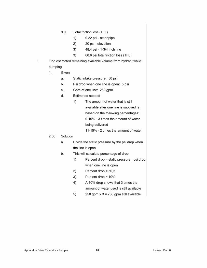
3) 68.6 psi total friction loss (TFL)
I. Find estimated remaining available volume from hydrant while
pumping
1. Given
a. Static intake pressure: 50 psi
b. Psi drop when one line is open: 5 psi
c. Gpm of one line: 250 gpm
d. Estimates needed
1) The amount of water that is still
available after one line is supplied is
based on the following percentages:
0-10% - 3 times the amount of water
being delivered
11-15% - 2 times the amount of water
2.00 Solution
a. Divide the static pressure by the psi drop when
the line is open
b. This will calculate percentage of drop
1) Percent drop = static pressure ¸ psi drop
when one line is open
2) Percent drop = 50¸5
3) Percent drop = 10%
4) A 10% drop shows that 3 times the
amount of water used is still available
5) 250 gpm x 3 = 750 gpm still available
Apparatus Driver/Operator - Pumper 61 Lesson Plan 6
Page 62
LESSON OUTLINE INSTRUCTOR NOTES
J. Mental Calculation of Correct Pump Discharge Pressure, GPM,
Friction Loss, and Nozzle Pressure
Often at a fire scene there is no time to develop the equations
needed to supply hoselines correctly; quick reference
approximations
Size of hose in.) Rule-of-thumb gpm)
1-1/2 100
1-3/4 200
2-1/2 250
3 500
4 1,000
5 1,500
Nozzle Optimum nozzle pressure (psi)
Fog - handline 100
Fog - master stream 100
Solid stream - handline 50
Solid stream - master stream 80
Device Friction loss psi)
Ladder pipes 10
Deck guns 10
Wye 10
Siamese 10
2-1/2 in. handline Friction loss psi)
flows gpm)
200 10
250 15
300 20
Apparatus Driver/Operator - Pumper 62 Lesson Plan 6
Page 63
LESSON OUTLINE INSTRUCTOR NOTES
0 K. Calculation of Nozzle Reaction of Hand and Master Streams
1. One of the basic laws of physics, Newton's third law,
states that for every action there is an equal and
opposite reaction
2. Water flowing out of nozzle will cause a backward
reaction
3. Since the reaction force is dependent upon amount of
water flowing through hose, it will therefore depend on
the size of the nozzle used and the nozzle pressure
4. Formulas
a. For straight-tipped solid stream nozzles
1) NR = 1.5d2NP
2) NR = nozzle reaction in lb.
d = nozzle diameter in.
NP = nozzle pressure in psi at the
nozzle
b.0 For fog pattern nozzles
1) Not based on standard formula because
nozzle diameter does not flow a
concentrated core of water
2) The formula is calculated as follows
NR = 0.0505QÖ¾NP
3) Where
a) NR = nozzle reaction in lb.;
Q = flow in gallons per minute;
NP = nozzle pressure in psi, at
the base of the nozzle
Apparatus Driver/Operator - Pumper 63 Lesson Plan 6
Page 64
LESSON OUTLINE INSTRUCTOR NOTES
L. Computing Maximum Lift of a Fire Department Pumper
1. Drafting water is the process of using water from a static
source, such as a pond, lake, or basin
2. Since water source is static, pump operator's job is force
water into the pump to be used on the fire ground
3. Process
a. For each 1 in. of mercury vacuum created,
water will be pushed into the non-collapsible
hose (or hard sleeve) a distance of 1.13 ft.
b. Lift measured from surface of static source to
centerline of pump, at sea level, will allow water
to be pushed to a height of
1) 14.7 psi x 2.304 ft./lb. = 33.86
2) 29.7 in. of mercury x 1.13 ft./lb./ = 33.81
c.0 The perfect vacuum necessary for the
theoretical lift of 33.9 ft. is almost impossible to
achieve, even in a laboratory.
d. Additional loss in optimum lift is accounted for
due to friction in the suction hose
e. Head loss, water temperature, atmospheric
pressure at the site location and condition of the
pump all contribute to lessening the theoretical
height that a pumper may raise water.
f. Limits practical lifts to
1) 28 ft. for an excellent rating
2) 25 ft. for a good rating
3) Pumpers should not be tested at a lift
Apparatus Driver/Operator - Pumper 64 Lesson Plan 6
Page 65
greater than 10 ft.
4) A primer on a fire department pumper
must be capable of raising water 10 ft.
into a dry pump through 20 ft. of
appropriate size hose in not more than
30 seconds
5) For effective operation, lift should be no
higher than 10 ft.
Apparatus Driver/Operator - Pumper 65 Lesson Plan 6
Page 66
LESSON OUTLINE INSTRUCTOR NOTES
g.0 Most pumpers in service lift somewhat less than
these figures because
1) Atmospheric pressure is higher on
clear, fair days and lower on cloudy or stormy
days
h.0 The pressure change will influence the
maximum lift
1) Altitude changes atmospheric pressure
by dropping approximately 1 in. of
mercury (1/2 psi) for every 1,000 ft. of
altitude above sea level
Apparatus Driver/Operator - Pumper 66 Lesson Plan 6
Page 67
LESSON OUTLINE INSTRUCTOR NOTES
3-4.1.2 Prerequisite Skills
A. Methods of power transfer
1. Mechanical linkage
a. This is not very common as a main method but
is usually included as part of the pump's
emergency back-up
b. It is operated from the pump itself
c. Manual override should be practiced frequently
2. Electrical or hydraulic
a. Common methods of power transfer
b. Procedure (before leaving the cab)
1) Disengage clutch
2) Place the road transmission in neutral
3) Place the clutch in proper gear
3. The normal arrangement is for power transfer case to be
controlled from inside cab of the apparatus.
a. If road transmission is not placed in correct
gear, pump will not turn at needed rpm to
operate effectively
b. Check that transmission is in correct gear;
observe speedometer reading after pump is
engaged
b. With the pump engaged, speedometer reading
will be between 10 to 15 mph, depending on the
apparatus
4. Locks
a. To prevent a manual transmission from slipping
out of gear, or an automatic
transmission gear selector from moving
during pumping operations, lock is
provided on transmission or
shift lever to hold it in proper gear for
pumping
Apparatus Driver/Operator - Pumper 67 Lesson Plan 6
Page 68
LESSON OUTLINE INSTRUCTOR NOTES
B. Priming Systems
1. Because centrifugal pumps have slippage; cannot prime
themselves
2. A source of vacuum or negative pressure needed to
draft
3. Positive displacement pumps
a. Largely used as priming pumps; not as main
source of pressure
b. Work on the principle that when pressure is
applied to a confined liquid, same outward
pressure is equally transmitted within the liquid
in all directions
c. There are two basic types of positive
displacement pumps
1) Piston pumps
a) All pistol pumps contain a
piston that moves back and forth
inside a cylinder
b) As the piston is driven forward,
air within the cylinder is
compressed; creates a higher
pressure inside pump than the
atmospheric pressure in
discharge manifold
c) This pressure causes the
discharge valve to open and air
to escape through discharge
lines
d) This action continues until
piston completes its travel on
forward stroke and stops
Apparatus Driver/Operator - Pumper 68 Lesson Plan 6
Page 69
LESSON OUTLINE INSTRUCTOR NOTES
e) At the point that pressures
equalize; discharge valve
closes
f) As the piston begins the return
stroke, area in cylinder behind
piston increases; pressure
decreases, creates partial
vacuum.
g) At this time, the intake valve
opens, allows air from suction
hose to enter pump
h) Atmospheric pressure forces
water to rise within hose until
piston completes its travel;
intake valve closes
i) More air is discharged until all
the air has been removed;
water enters
j) The pump is now considered to
be primed
2) Rotary gear pump
a) Consists of two gears that
rotate in a tightly meshed
pattern inside a watertight case
b) Gears are constructed so they
contact each other; in close
proximity to the case
c) With this arrangement,
watertight and airtight pockets
are formed by the gears within
case as they turn from intake to
outlet
d) Total amount of water that can
be pumped depends on size of
pockets
Apparatus Driver/Operator - Pumper 69 Lesson Plan 6
Page 70
LESSON OUTLINE INSTRUCTOR NOTES
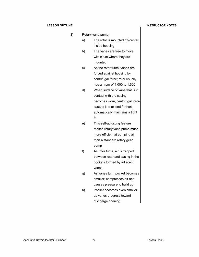
3) Rotary vane pump
a) The rotor is mounted off-center
inside housing
b) The vanes are free to move
within slot where they are
mounted
c) As the rotor turns, vanes are
forced against housing by
centrifugal force; rotor usually
has an rpm of 1,000 to 1,500
d) When surface of vane that is in
contact with the casing
becomes worn, centrifugal force
causes it to extend further;
automatically maintains a tight
fit
e) This self-adjusting feature
makes rotary vane pump much
more efficient at pumping air
than a standard rotary gear
pump
f) As rotor turns, air is trapped
between rotor and casing in the
pockets formed by adjacent
vanes
g) As vanes turn, pocket becomes
smaller; compresses air and
causes pressure to build up
h) Pocket becomes even smaller
as vanes progress toward
discharge opening
Apparatus Driver/Operator - Pumper 70 Lesson Plan 6
Page 71
LESSON OUTLINE INSTRUCTOR NOTES
i) Pressure reaches its maximum
level, forcing trapped air out of
pump
j) Water forced into pump by
atmospheric pressure until
pump fills with water
k) At this point, pump is primed
C Drafting Operations
1. Draft procedure
a. Select proper water source capable of drafting
operation
b. Maneuver apparatus to draft site
c. Stop before reaching water source to connect
hard suction hose and strainer to pumper
d. Attach strainer to hard suction hose
e. Attach hard suction hose to intake
f. Move to final draft position
g.. Minimize lift distances
h. Surround strainer with at least 24 in. of water on
all sides
i. Properly place pump in gear
j. Prime pump
k. Systems check
1) Check couplings on hard suction hose
for airtight seal
2) Check that all drains are closed
3) Check that intake relief valve outlet is
capped
4) Check that circulator valve or booster
cooling valve is completely
turned off (if applicable)
Apparatus Driver/Operator - Pumper 71 Lesson Plan 6
Page 72
LESSON OUTLINE INSTRUCTOR NOTES
D Pressure relief systems
1. Automatic pressure control
a. The volume of water moving through pump may
change suddenly when a nozzle is shut down
rapidly or when setting is changed on a variable
gallonage nozzle
b. The fire fighter on the nozzle cannot tolerate
any sudden changes in pressure.
c. During the critical stages of the attack, a sudden
change in pressure can be disastrous
d. A shutdown of one line can mean surge on
others so that some type of automatic pressure
regulation is essential to ensure safety of
personnel operating hoselines; directs excess
pressure to intake side of pump
2. Relief valve
a. The main action is to relieve excess pressure
within the pump discharge
b. An adjustable spring-loaded pilot valve actuates
the relief valve to bypass water from discharge
to intake chamber of pump
c. Rerouting permits pump to continue in operation
when pressure rises above the working
pressure
d. When the discharge pressure rises higher than
allowed by the pilot valve setting, the spring in
the pilot valve moves; permits water to dump
back into pump intake
Apparatus Driver/Operator - Pumper 72 Lesson Plan 6
Page 73
LESSON OUTLINE INSTRUCTOR NOTES
3. Pressure governor
a. For centrifugal pumps only
b. It is pressure actuated to adjust engine throttle
c. The main feature of a pressure governor is that
it regulates power output of engine to match set
pump discharge requirements
d. When the pressure in the discharge chambers
of the pump exceeds pressure necessary to
maintain safe fire streams, engine speed is
reduced; speed of impellers dependent on
engine speed
E. Pump Gauges
1. Vacuum gauge
a. The gauge is usually calibrated from 0 to 600
psi positive pressure; 0 to 30 in. of vacuum on
the negative side
b. This gauge provides an indication of vacuum
present at intake of pump during priming or
when pump is operating from draft
c. It also provides an indication of residual
pressure when pump is operating from a
hydrant or is receiving water through a supply line from
another pump
2. Pressure gauge
a. A pressure gauge is calibrated to
measure 600 psi unless pumper is equipped to
supply high-pressure fog streams, in which case
the gauge may be calibrated up to 1,000 psi
b. The pressure gauge registers the pump
discharge pressure
Apparatus Driver/Operator - Pumper 73 Lesson Plan 6
Page 74
LESSON OUTLINE INSTRUCTOR NOTES
c. On a centrifugal pump, may also be a
compound gauge; both intake and discharge of
centrifugal pump will register negative pressure
during priming
d. Pressure gauges can be connected to individual
discharge lines
e. An individual line gauge is the only way to be
certain that the pump has been adjusted
properly
3. Flowmeter
a. Flow meters virtually eliminate possibility of
operator error; provide an accurate reading of
water flow in gallons per minute
b. The number displayed on the flowmeter requires
no further calculation; reflects how much water
is moving through discharge valve
c. NFPA 1901 allows flow meters to be used
instead of pressure gauges on all 2-1/2 in. or
larger outlets
F. Transfer Valve
1. Found on two stage pumps
2. May be manual or power operated
3. Function is to change pump from series to parallel or
from parallel to series operation
3. Two positions
a. Series
b. Pressure
3. When pump is use at more than one half of rated
capacity, parallel operation should be used
a. Example: When a 1,000 gpm pump is pumping
more than 500 gpm - parallel operation should
be used
Apparatus Driver/Operator - Pumper 74 Lesson Plan 6
Page 75
LESSON OUTLINE INSTRUCTOR NOTES
G. Auxiliary Cooling Systems
1. The primary function of auxiliary coolers is to control the
temperature of cooling water in the apparatus engine
during pumping operations
2. Two types: marine and immersion
a. Marine
1) Inserted in one of the hoses used in
engine cooling system; engine coolant
must travel through it as it circulates
through system
2) Coolant from radiator passes through
tubes in cooler; colder water from fire
pump comes in contact with metal tubes
3) Colder water conducts heat away from
tubes; reduces temperature of coolant
flowing through them
4) A valve on the pump panel is used to
control the amount of water being
supplied to auxiliary cooler
b. Immersion
1) Mounted with radiator coolant passing
through body of the cooler
2) Water from fire pump passes through
tubing mounted inside the cooler;
immersed in coolant
3) As cooler water from fire pump passes
through tubing, heat from coolant is
absorbed by tubing and dissipated in
water from pump
4) Valve on pump panel used to control
degree of cooling desired
Apparatus Driver/Operator - Pumper 75 Lesson Plan 6
Page 76
LESSON OUTLINE INSTRUCTOR NOTES
H Nozzles
1. Solid stream
a. Flow is constant and determined by tip size
b. Only control is shutoff
1) Flow can be varied somewhat by
partially closing shutoff; creates
extreme turbulence and destroys
stream
2) For normal fire fighting operations,
should be operated fully open
c. Pressures
1) Handlines - 50 psi at tip (standard)
2) Master streams - 80 to 100 psi at tip
d. This type of nozzle is rarely used for interior
operations; may be used to great advantage in
exterior, defensive operations
e. Solid-stream nozzles produce little or no spray
f. Internal blades called vanes designed into
nozzle to create a straighter stream
Apparatus Driver/Operator - Pumper 76 Lesson Plan 6
Page 77
LESSON OUTLINE INSTRUCTOR NOTES
2. Basic types of fog nozzles
a. Most common type is peripheral jet
1) Adjustable pattern, usually from straight
stream to about 120o
2) Of more importance to the
driver/operator, most, except for very
old models, are constant flow; they
deliver same gpm in all patterns
3) Adjustable flows are very common
a) 1-1/2 in. flows commonly vary
from 30-120 gpm
b) 2-1/2 in. flows commonly vary
from 120-250 gpm
c) 2-1/2 in. turbojet operated in
flush position flows about 325-
350 gpm
d) Stream is not good, but if
heavy, blitz-type stream is
needed, this may be used.
4) Department has standard operating
procedures specifying
a) normal gpm setting for all
adjustable-flow nozzles
b) Settings are not changed
without notifying driver/operator
5) If 1-1/2 in. are normally set on 95 gpm,
can be changed to either 60 or 120
without much effect on tip pressure
6) The most standard and desired
pressure is 100 psi
b. For fixed-flow nozzles, driver/operator should
know rated flow
Apparatus Driver/Operator - Pumper 77 Lesson Plan 6
Page 78
LESSON OUTLINE INSTRUCTOR NOTES
3. Flows
a. The critical factor regarding flows is that
driver/operator must be familiar with nozzles in
use by department
b. Where adjustable flow nozzles are used, must
be a standard operating procedure regarding
flow settings and changes of flow settings
4. Automatic nozzles
a. Automatic nozzles require different way of
thinking, both for driver/operator and nozzle
person
b. Features
1) Slide shutoff valve enables nozzle
person to vary flow without destroying
stream characteristics
2) Other automatic nozzles use a ball-type
shutoff; produce very poor streams
when partially shut off
3) These may be so poor that nozzle
operators will refuse to control flow from
nozzle; ask driver/operator to control it
from pump
Apparatus Driver/Operator - Pumper 78 Lesson Plan 6
Page 79
LESSON OUTLINE INSTRUCTOR NOTES
3-4.2 Pump a supply line in a relay pumping operation
A. Source pumper
1. Connect to water supply
2. Connect supply line to relay pumper
3. Start flow of water when signaled by relay pumper
4. When relay is established - increase pressure and
maintain desired intake pressure to relay pumper
B. Relay pumper
1. Connect hose line from source pumper
2. Connect discharge lines to other pumper or appliance
3. Signal source pumper to start flow
4. Pump out of gear
5. Open discharge valve
6. When water flows out of discharge - engage pump
7. Close discharge valve
8. Open valves to charge attack lines
9. Adjust throttle for proper pump pressure
10.
C. Flow and pressure based on
1. Size of hose line
2. Length of hose line
D. Shut down in reverse order
1. Relay pumper shuts down first
Apparatus Driver/Operator - Pumper 79 Lesson Plan 6
Page 80
LESSON OUTLINE INSTRUCTOR NOTES
3-4.3 Produce a foam fire stream
A. Objective is to produce properly proportioned foam
B. Steps for using an external eductor
1. Assemble necessary equipment
a. Foam concentrate
b. Foam eductor
1) Eductor and nozzle must have same
gpm rating
c. Foam nozzle
d. Hose
2. Connect equipment
a. Connect eductor to pump discharge
b. Connect hose line to eductor
c. Connect nozzle to hose line
1) Length of hose line should not exceed
manufacturers recommendations
d. Open foam concentrate and insert pickup tube
e. Place pump in gear and open discharge valve
f. Increase pump pressure to that required for the
eductor
C. Steps for using a pump proportioner with foam tank (if equipped)
1. Two kinds of systems
a. Around the pump proportioner
1) With pump in gear
a) Open bypass valve
b) Set metering valve for percent
foam concentration
c) Attach hose line or lines
b. Balanced pressure proportioner
1) With pump in gear
a) Activate foam concentrate
pump
b) Set metering valve for percent
foam concentrate
Apparatus Driver/Operator - Pumper 80 Lesson Plan 6
Page 81
c) Attach hose line or lines
Apparatus Driver/Operator - Pumper 81 Lesson Plan 6
Page 82
LESSON OUTLINE
INSTRUCTOR NOTES
3-4.4 Change water supply source while pumping an attack line
A. Objective is to maintain flow to attack line while changing from
apparatus water tank to external water source
B. Steps
1. Connect pumper to external water source
2. Deploy attack line
3. Place pump in gear
4. Pump attack line using tank water
5. Adjust pump for proper discharge pressure and flow
6. Open suction valve to take water from external source
7. Close tank valve
8. Pump attack line using external water source
Apparatus Driver/Operator - Pumper 82 Lesson Plan 6
Page 83
REVIEW
I. Discuss key lesson points.
II. Ask questions on the material covered.
III. Review material that may be unclear.
IV. Administer test or quiz.
V. Critique test or quiz.
SUMMARY
I. Summarize what has been covered.
II. Relate what has been covered to the next lesson.
Apparatus Driver/Operator - Pumper 83 Lesson Plan 6