Resistori protetti per frenatura - Protected braking resistors 11/05/2012 - Con riserva di modifiche tecniche - Specifications subject to change without notice. MRIG G20K MRIG P20K MRIG G30K MRIG P30K MRIG G40K MRIG P40K MRIG G50K MRIG P50K MRIG G60K MRIG P60K Dimensioni a) Dimensions a) IP20-23 IP20-23 IP20-23 IP20-23 IP20-23 IP20-23 IP20-23 IP20-23 IP20-23 IP20-23 L mm 650 650 650 870 870 870 870 870 1050 1050 H b) mm 450 450 660 860 660 860 660 860 660 860 M mm 450 450 450 450 450 625 625 625 625 625 I mm 625 625 625 845 845 845 845 845 1025 1025 T mm 350 350 350 350 350 450 450 450 450 450 Peso medio Avg. weight kg 35 40 40 50 60 60 70 70 80 80 Golfari Lifting rings 2 2 2 2 2 4 4 4 4 4 a) Tolleranza ± 2% su tutte le dimensioni nominali, ove non altrimenti specificato Tolerance of ± 2% on all nominal dimensions unless otherwise specified b) Escluso golfari - Lifting rings excluded Resistori protetti per frenatura Robusti, compatti ed efficienti, gli MRIG sono resistori in armadio di alta potenza ed alta qualità, per frenatura, test, sicurezza, o applicazioni speciali. La possibilità di ospitare i resistori RPTM, GHPR, RCC e RPSC permette di adattarsi agli impieghi più diversi, dalla frenatura di sicurezza ai banchi di carico continuo, dagli elevati carichi dinamici ai carichi per test di precisione. L’armadio di protezione è realizzato con materiali di alta qualità e trattamenti tecnici che assicurano lunga durata e robustezza anche in ambienti difficili. E’ accuratamente dimensionato per l’impiego dei resistori I.R.E.: a seconda del resistore impiegato, sono disponibili due tipologie differenti: “G” con i GHPR e “P” con gli RPTM o configurazioni speciali. Il termostato di sicurezza è disponibile in diverse temperature, i terminali sono accessibili dal basso o da un lato. Le caratteristiche indicate si riferiscono a condizioni di laboratorio, con il resistore posizionato orizzontalmente su una superficie piana, senza ostruzione delle aperture di ventilazione, all’interno di uno spazio libero con buone condizioni di irradiazione. Un posizionamento inadeguato o l’esposizione alla luce solare diretta possono ridurre significativamente la prestazione termica. Protected braking resistors Rugged, compact, efficient, MRIG is a high power, high quality resistor box, for braking, test, safety or special applications. The possibility to house RPTM, GHPR, RCC and RPSC resistor series, makes it possible to fit the most different needs, from occasional safety braking to continuous test banks, from high dynamic load to precision test load. The protection box is made with high quality material and technical treatments that ensure long life and consistency also in difficult environment. It is carefully dimensioned for the application of I.R.E. resistors: depending on the employed resistor, two different types are available, “G” with GHPRs and “P” with RPTMs or special configurations. A safety thermal switch is available for various temperature, power and safety terminals are accessible from the bottom or from one side. Rated characteristics refer to laboratory conditions, with the resistor laying horizontally on a flat surface with no obstruction of the inlet or outlet openings, inside a large free volume with good irradiation condition. Poor positioning and exposure to direct sunlight can significantly reduce thermal performance. DrMRIG www.movitecnic.fr
Transcript
Resistori protetti per frenatura - Protected braking resistors
11/05/2012 - Con riserva di modifiche tecniche - Specifications subject to change without notice.
a) Tolleranza ± 2% su tutte le dimensioni nominali, ove non altrimenti specificato Tolerance of ± 2% on all nominal dimensions unless otherwise specified
b) Escluso golfari - Lifting rings excluded
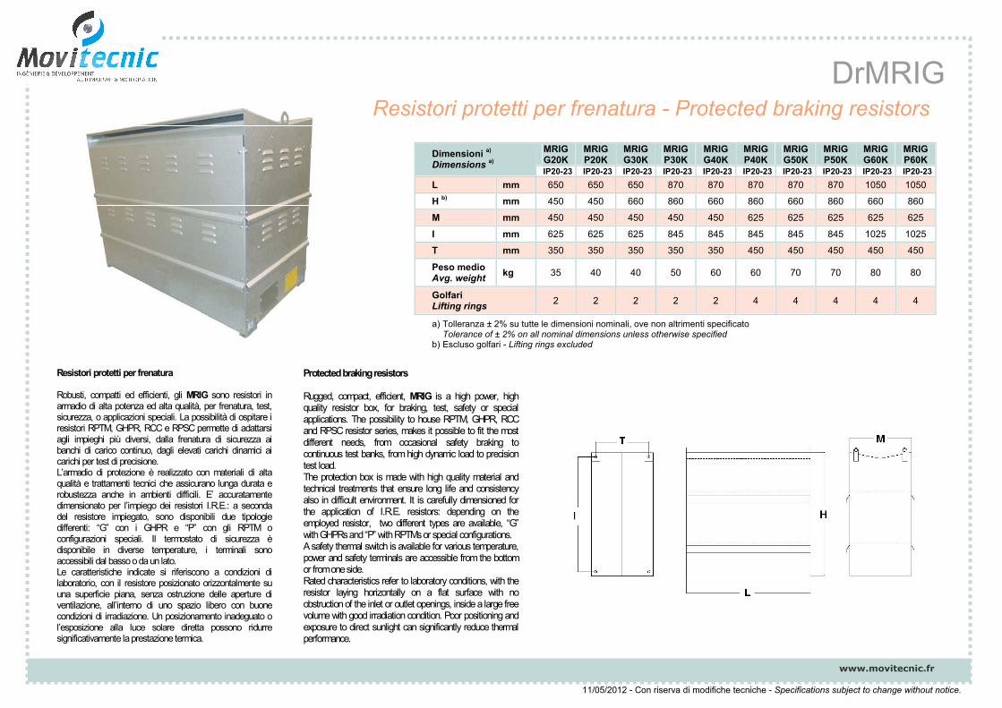
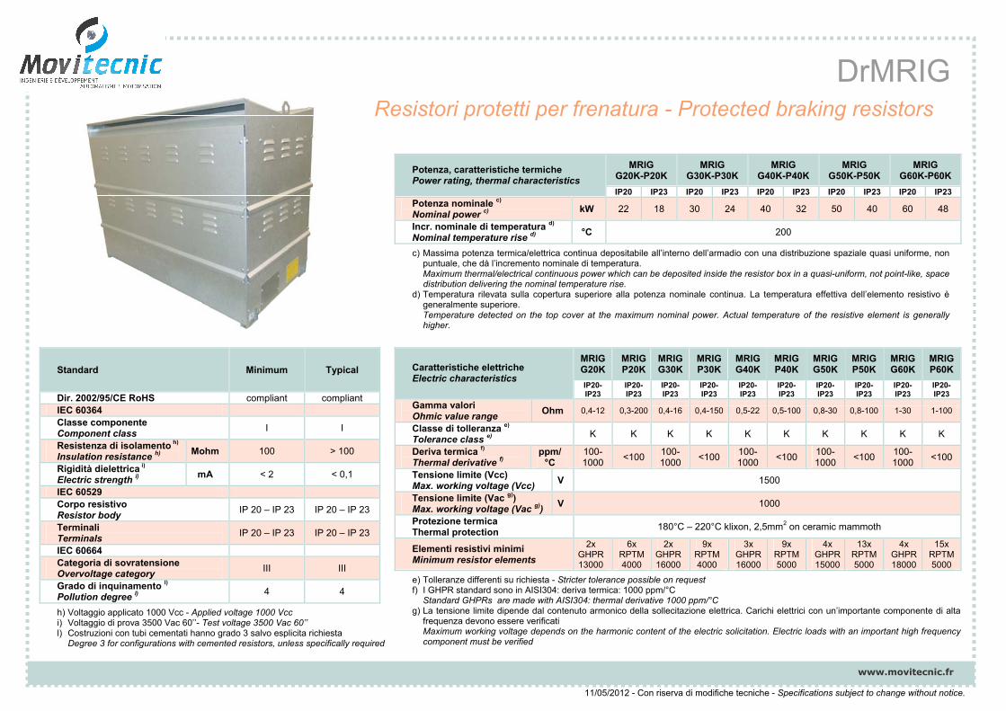
Resistori protetti per frenatura
Robusti, compatti ed efficienti, gli MRIG sono resistori in armadio di alta potenza ed alta qualità, per frenatura, test, sicurezza, o applicazioni speciali. La possibilità di ospitare i resistori RPTM, GHPR, RCC e RPSC permette di adattarsi agli impieghi più diversi, dalla frenatura di sicurezza ai banchi di carico continuo, dagli elevati carichi dinamici ai carichi per test di precisione. L’armadio di protezione è realizzato con materiali di alta qualità e trattamenti tecnici che assicurano lunga durata e robustezza anche in ambienti difficili. E’ accuratamente dimensionato per l’impiego dei resistori I.R.E.: a seconda del resistore impiegato, sono disponibili due tipologie differenti: “G” con i GHPR e “P” con gli RPTM o configurazioni speciali. Il termostato di sicurezza è disponibile in diverse temperature, i terminali sono accessibili dal basso o da un lato. Le caratteristiche indicate si riferiscono a condizioni di laboratorio, con il resistore posizionato orizzontalmente su una superficie piana, senza ostruzione delle aperture di ventilazione, all’interno di uno spazio libero con buone condizioni di irradiazione. Un posizionamento inadeguato o l’esposizione alla luce solare diretta possono ridurre significativamente la prestazione termica.
Protected braking resistors
Rugged, compact, efficient, MRIG is a high power, high quality resistor box, for braking, test, safety or special applications. The possibility to house RPTM, GHPR, RCC and RPSC resistor series, makes it possible to fit the most different needs, from occasional safety braking to continuous test banks, from high dynamic load to precision test load. The protection box is made with high quality material and technical treatments that ensure long life and consistency also in difficult environment. It is carefully dimensioned for the application of I.R.E. resistors: depending on the employed resistor, two different types are available, “G” with GHPRs and “P” with RPTMs or special configurations. A safety thermal switch is available for various temperature, power and safety terminals are accessible from the bottom or from one side. Rated characteristics refer to laboratory conditions, with the resistor laying horizontally on a flat surface with no obstruction of the inlet or outlet openings, inside a large free volume with good irradiation condition. Poor positioning and exposure to direct sunlight can significantly reduce thermal performance.
DrMRIG
www.movitecnic.fr
Resistori protetti per frenatura - Protected braking resistors
11/05/2012 - Con riserva di modifiche tecniche - Specifications subject to change without notice.
Standard Minimum Typical
Dir. 2002/95/CE RoHS compliant compliant IEC 60364 Classe componente Component class
I I
Resistenza di isolamento h)
Insulation resistance h) Mohm 100 > 100
Rigidità dielettrica i)
Electric strength i) mA < 2 < 0,1
IEC 60529 Corpo resistivo Resistor body
IP 20 – IP 23 IP 20 – IP 23
Terminali Terminals
IP 20 – IP 23 IP 20 – IP 23
IEC 60664 Categoria di sovratensione Overvoltage category
III III
Grado di inquinamento l)
Pollution degree l) 4 4
h) Voltaggio applicato 1000 Vcc - Applied voltage 1000 Vcc i) Voltaggio di prova 3500 Vac 60’’- Test voltage 3500 Vac 60’’ l) Costruzioni con tubi cementati hanno grado 3 salvo esplicita richiesta
Degree 3 for configurations with cemented resistors, unless specifically required
Tensione limite (Vac g)) Max. working voltage (Vac g))
V 1000
Protezione termica Thermal protection
180°C – 220°C klixon, 2,5mm2 on ceramic mammoth
Elementi resistivi minimi Minimum resistor elements
2x GHPR 13000
6x RPTM 4000
2x GHPR 16000
9x RPTM 4000
3x GHPR 16000
9x RPTM 5000
4x GHPR15000
13x RPTM 5000
4x GHPR 18000
15x RPTM 5000
e) Tolleranze differenti su richiesta - Stricter tolerance possible on request f) I GHPR standard sono in AISI304: deriva termica: 1000 ppm/°C
Standard GHPRs are made with AISI304: thermal derivative 1000 ppm/°C g) La tensione limite dipende dal contenuto armonico della sollecitazione elettrica. Carichi elettrici con un’importante componente di alta
frequenza devono essere verificati Maximum working voltage depends on the harmonic content of the electric solicitation. Electric loads with an important high frequency component must be verified
c) Massima potenza termica/elettrica continua depositabile all’interno dell’armadio con una distribuzione spaziale quasi uniforme, non puntuale, che dà l’incremento nominale di temperatura. Maximum thermal/electrical continuous power which can be deposited inside the resistor box in a quasi-uniform, not point-like, space distribution delivering the nominal temperature rise.
d) Temperatura rilevata sulla copertura superiore alla potenza nominale continua. La temperatura effettiva dell’elemento resistivo è generalmente superiore. Temperature detected on the top cover at the maximum nominal power. Actual temperature of the resistive element is generally higher.
DrMRIG
www.movitecnic.fr
u i
11/05/2012 - Con riserva di modifiche tecniche - Specifications subject to change without notice.
Grazie per aver scelto un resistore di frenatura IRE. Le seguenti istruzioni forniscono informazioni e precauzioni utili alla corretta installazione, operatività e manutenzione del resistore. Si prega di rendere disponibile questo foglio di istruzioni all’utilizzatore finale. Un impiego non corretto può causare danni alle persone o guasti inattesi al resistore e alle apparecchiature ad esso collegate e può far decadere la garanzia.
AVVERTENZAQuesto resistore deve essere installato e utilizzato unicamente da personale specializzato, al corrente delle principali norme di sicurezza. Nel luogo di installazione e utilizzo devono essere presenti i dispositivi di sicurezza necessari per la prevenzione degli incidenti, conformemente con la legislazione localmente vigente.
ISTRUZIONI DI INSTALLAZIONE Questo dispositivo deve sempre essere conservato in luogo chiuso, asciutto, al riparo da vibrazioni e polvere. Il resistore deve essere montato in posizione orizzontale, su una superficie piana, vincolato alla superficie tramite i piedi di ancoraggio, lasciando libere le bocche di ventilazione poste sui lati e sul tetto. Vedi disegni. Assicurarsi che il resistore sia installato in un ambiente coerente con il proprio grado di protezione, sufficientemente ampio e ventilato e che la temperatura
dell’ambiente non superi i 50 °C.Dopo l’installazione una indicazione del rischio di ustione riportante la dicitura o i simboli internazionali di SUPERFICIE CALDA – NON TOCCARE sarà collocata in una posizione ben visibile. Non installare il resistore vicino a legno, carta o altro materiale combustibile. Facendo ciò si presenta il rischio di esplosioni o incendio. I cavi e le connessioni devono uscire dal fondo o dal lato del resistore, evitare il contatto del resistore con i cavi di alimentazione o con qualsiasi altro cavo, utilizzare i pressacavi montati ed usare cavi di sezione adeguata alla corrente elettrica ed alla potenza applicata.Stringere tutte le viti o bulloni dei terminali fino al livello specificato, per evitare il rischio di incendi (M5 6Nm, M6 10Nm, M8 18Nm).Il termostato di sicurezza può danneggiarsi dopo l’esposizione ad una temperatura significativamente più elevata di quella su cui è tarato. Ogni volta che viene collegato un termostato dopo un evento di surriscaldamento deve essere considerato difettoso e le sue indicazioni inaffidabili. Alcuni componenti del resistore sono ceramici ed hanno un comportamento fragile. Questi componenti sono stati progettati ed assemblati per sopportare le sollecitazioni standard di un ambiente industriale; evitare cadute o shock meccanici.
ISTRUZIONI DI SICUREZZAPrevenzione dei rischi elettrici: prima di iniziare l’installazione, il cablaggio o l’ispezione, disconnettere l’alimentazione, aspettare alcuni minuti e verificare che non siano presenti tensioni residue con un voltmetro. Prevenzione incendi: installare il resistore di frenatura su una superficie non combustibile, l’installazione direttamente sopra o vicino ad una superficie combustibile può causare incendio. Utilizzare i segnali di allarme per togliere l’alimentazione del resistore, non farlo può provocare surriscaldamento del resistore, causare la rottura del resistore e lo sviluppo di scintille o fiamme. Prevenzione infortuni: il collegamento deve essere effettuato da personale autorizzato e qualificato, per evitare danni al prodotto ed alle apparecchiature ad esso collegate. Durante l’accensione e per un certo periodo dopo lo spegnimento, non toccare il resistore di frenatura in quanto è caldo. Il contatto può provocare ustioni. Trasportare il prodotto in modo corretto, coerente con la sua forma ed il suo peso. Non farlo può provocare infortuni. Installare il resistore su un piano abbastanza solido da sostenere il suo peso e gli eventuali carichi dinamici previsti. Non modificare il resistore o alcuna delle sue parti, in caso contrario la garanzia decade.
DrMRIG
www.movitecnic.fr
u
11/05/2012 - Con riserva di modifiche tecniche - Specifications subject to change without notice.
Thank you for choosing this IRE product. These instructions must be followed to ensure safe and proper installation, operation and maintenance of the equipment. They should be brought to the attention of anyone who installs, operates or maintains this equipment. Ignoring these instructions can result in serious or fatal injury, damage to the product or related equipment and may invalidate the warranty.
WARNINGS This equipment is intended for installation and use by qualified personnel, familiar with relevant safety requirements. Safety equipment necessary for the prevention of accidents at the installation and operating site must be provided in accordance with local regulations.
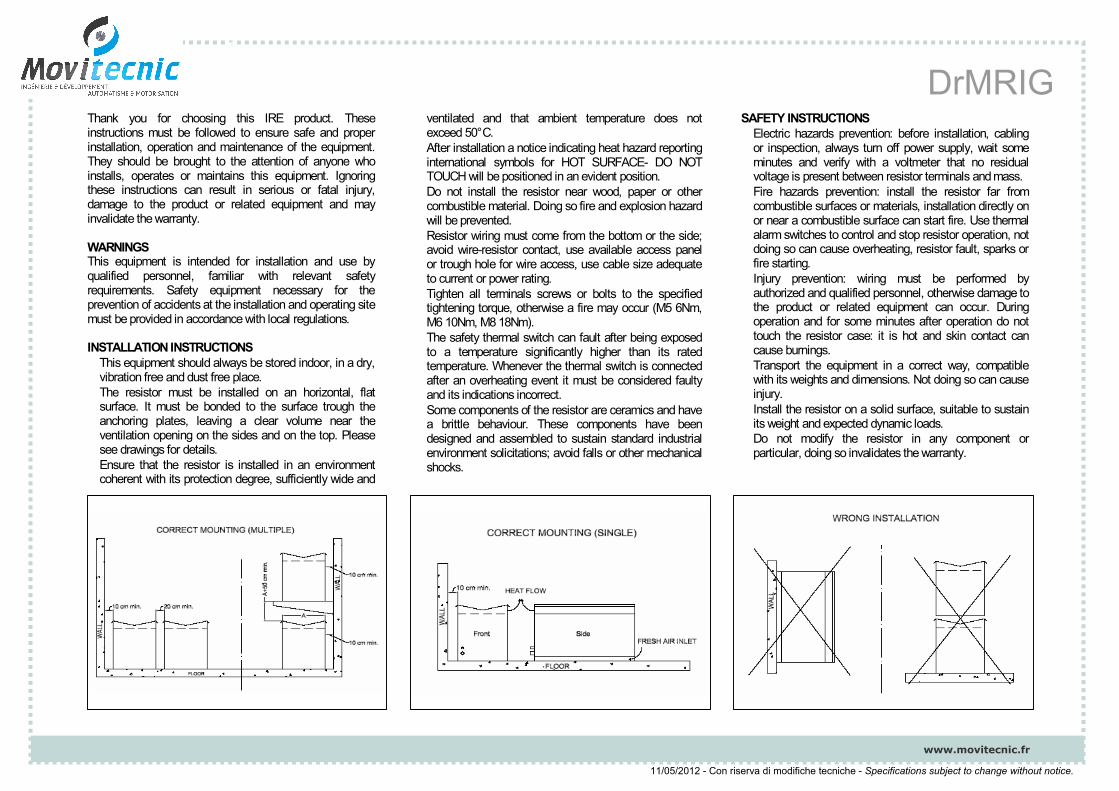
INSTALLATION INSTRUCTIONS This equipment should always be stored indoor, in a dry, vibration free and dust free place. The resistor must be installed on an horizontal, flat surface. It must be bonded to the surface trough the anchoring plates, leaving a clear volume near the ventilation opening on the sides and on the top. Please see drawings for details. Ensure that the resistor is installed in an environment coherent with its protection degree, sufficiently wide and
ventilated and that ambient temperature does not exceed 50°C. After installation a notice indicating heat hazard reporting international symbols for HOT SURFACE- DO NOT TOUCH will be positioned in an evident position. Do not install the resistor near wood, paper or other combustible material. Doing so fire and explosion hazard will be prevented. Resistor wiring must come from the bottom or the side; avoid wire-resistor contact, use available access panel or trough hole for wire access, use cable size adequate to current or power rating. Tighten all terminals screws or bolts to the specified tightening torque, otherwise a fire may occur (M5 6Nm, M6 10Nm, M8 18Nm). The safety thermal switch can fault after being exposed to a temperature significantly higher than its rated temperature. Whenever the thermal switch is connected after an overheating event it must be considered faulty and its indications incorrect. Some components of the resistor are ceramics and have a brittle behaviour. These components have been designed and assembled to sustain standard industrial environment solicitations; avoid falls or other mechanical shocks.
SAFETY INSTRUCTIONSElectric hazards prevention: before installation, cabling or inspection, always turn off power supply, wait some minutes and verify with a voltmeter that no residual voltage is present between resistor terminals and mass. Fire hazards prevention: install the resistor far from combustible surfaces or materials, installation directly on or near a combustible surface can start fire. Use thermal alarm switches to control and stop resistor operation, not doing so can cause overheating, resistor fault, sparks or fire starting. Injury prevention: wiring must be performed by authorized and qualified personnel, otherwise damage to the product or related equipment can occur. During operation and for some minutes after operation do not touch the resistor case: it is hot and skin contact can cause burnings. Transport the equipment in a correct way, compatible with its weights and dimensions. Not doing so can cause injury. Install the resistor on a solid surface, suitable to sustain its weight and expected dynamic loads. Do not modify the resistor in any component or particular, doing so invalidates the warranty.