25
Drone Claw Created by Ruiz Brothers Last updated on 2018-06-18 11:36:06 PM UTC
Drone ClawCreated by Ruiz Brothers
Last updated on 2018-06-18 11:36:06 PM UTC
244445556777788
9101010
11111111
11111212121313
14141415151617191921222323242425252526
Guide Contents
Guide ContentsOverview
CPX Drone ClawLight Pipes3D Printed Light Leak Proof CaseThe ClawTrigger with Light PipesPayload WeightParts
Circuit Playground ExpressMicro Servo - MG90S High Torque Metal GearPremium Female/Male 'Extension' Jumper Wires - 40 x 6" (150mm)PLA Filament for 3D Printers - 2.85mm Diameter - Black - 1.0KgLithium Ion Polymer Battery - 3.7v 500mAhUltimaker 3 - 3D Printer
Circuit DiagramCode
WebUSBMapping LEDs to Controls
3D PrintingWhat If I Don't Have A 3D Printer?Slice Settings
Supports
Fusion 360 filesSTL filesDesign Source FilesLeg Claw Supports and Support BlocksBreakaway supportsCircuit Playground Case SupportsNinjaFlex Port Coverts
AssemblePrep WiresConnect wires to CPXCPX caseLipoCover + LegReset Button ExtensionAlign caseLeg ClawRight Claw - Servo HornPrep Light PipeLeg InstallLeg Claw InstallFront LegsWire clipAttach wire clipConnect Jumper wiresWire Slack TuckLED Cover Clip
© Adafruit Industries https://learn.adafruit.com/drone-claw Page 2 of 26
2626
Port CoversFly
© Adafruit Industries https://learn.adafruit.com/drone-claw Page 3 of 26

Overview
CPX Drone Claw
In this project we’ll show you how to build a DIY Drone Claw.
We designed and 3D Printed a claw attachment for the DJI Mavic Pro. This doesn’t
obstruct the vision sensors so we can fly safely with obstacle avoidance.
This build can be used for educational projects like the classic egg drop or even
delivering small objects.
You can also use this to pick up the trash, carry objects to research sites or even
camping grounds. There’s a lot of tasks that you can do with a claw attachment.
Light Pipes
The on board light sensor on the Circuit Playground Express activates the claw with a light pipe connected to the LEDs on the drone!
3D Printed Light Leak Proof Case
© Adafruit Industries https://learn.adafruit.com/drone-claw Page 4 of 26

The Circuit Playground Express mounts inside our 3d printed enclosure to block out all light, so you can use it on any project that uses the light sensor!
The Claw
The claw is actuated using a micro servo and remotely triggered using the remote
controller.
We’re using the Light Sensor on the Adafruit Circuit Playground to detect when
the LEDs are on.
Trigger with Light Pipes
A light pipe tunnels the LEDs on the Drone into the 3D printed enclosure.
So the servo opens and closes when the LEDs are remotely turned on and off.
Payload Weight
The Mavic Pro has a maximum payload capacity of about 2 lbs or 990 grams.
This gives us enough lift for use in situations such as research, where you would need to move around small specimens or even something like beach clean up!
© Adafruit Industries https://learn.adafruit.com/drone-claw Page 5 of 26

Parts
Listed below are all the components and hardware screws you'll need to build you own drone claw!
1 x 130mm 02.0/1.0 Heat Shrink130mm 02.0/1.0 Heat Shrink
ADD TO CART
1 x 1.75mm Taulman T-Glase Clear Filament (130mm long)1.75mm Taulman T-Glase Clear Filament
BUY NOW
1 x M3x6mm + nutsM3x6mm + nuts
BUY NOW
2 x M2x5mmM2x5mm
BUY NOW
© Adafruit Industries https://learn.adafruit.com/drone-claw Page 6 of 26

4 x M3x16mmM3x16mm
BUY NOW
1 x M3x10mmM3x10mm
BUY NOW
1 x M3 x 3mm Female Thread Brass KnurledM3 x 3mm Female Thread Brass Knurled
BUY NOW
1 x M2.5x5mmM2.5x5mm
BUY NOW
Your browser does not support the video tag. Circuit Playground Express
$24.95OUT OF STOCK
OUT OF STOCK
Micro Servo - MG90S High Torque Metal Gear
$9.95IN STOCK
ADD TO CART
Premium Female/Male 'Extension' Jumper Wires - 40 x 6" (150mm)
$3.95IN STOCK
ADD TO CART
PLA Filament for 3D Printers - 2.85mm Diameter - Black - 1.0Kg
$39.95IN STOCK
ADD TO CART
© Adafruit Industries https://learn.adafruit.com/drone-claw Page 7 of 26

Lithium Ion Polymer Battery - 3.7v 500mAh
$7.95IN STOCK
ADD TO CART
Ultimaker 3 - 3D Printer
$3,750.00IN STOCK
ADD TO CART
© Adafruit Industries https://learn.adafruit.com/drone-claw Page 8 of 26

Circuit DiagramTake a moment to review the components in the circuit diagram. This illustration is meant for referencing wired connections - The length of wire, position and size ofcomponents are not exact.
Connections:
Servo
The Middle RED wire connect to VOUTYellow connects to A1Brown connects to GND
The 500 mAh battery connects to the JST port on the Circuit Playground Express
Wire length
CPX: 110mmPETT: 130 mm (1.75mm)
Screws:
CPX: Three M3x6mm + nuts
Case:
Two M2x5mm
Cover:
Four M3x12mm
Claw left:
One M3x6mm + thread insert
Claw right:
One M2.5x5mm
© Adafruit Industries https://learn.adafruit.com/drone-claw Page 9 of 26

CodeThe Makecode activates the claw when the Circuit Playground Express detects light. Use the embedded code to run in a chrome browser below:
WebUSB
Makecode can also pair with your Circuit Playground Express through a chrome
web browser by going to this address: https://makecode.adafruit.com/beta?
webusb=1#editor (https://adafru.it/Bct)
or visit the project
here: https://makecode.com/_WgrDeHKLf0RH (https://adafru.it/Bcu)
This means code edit will upload directly to the Circuit Playground Express without
the need to drag and drop file onto it!
Follow the instruction to set up your board and you'll be able to quickly send code
to Circuit Playground Express!
Mapping LEDs to Controls
We can easily map the "Head LEDs" to one of the customization buttons. These two buttons are located on the bottom of the controller.
First we'll connect our mobile device to the controller and then tap on the three dots on the upper right side of the screen.
We can edit the custom controls for the C1 and C2 button by tapping to the third icon shaped like a remote controller. Tap on one of the buttons and a drop down menuwill show us all of the available options we can map.
© Adafruit Industries https://learn.adafruit.com/drone-claw Page 10 of 26

3D Printing
What If I Don't Have A 3D Printer?
Not to worry! You can use a 3D printing service such as 3DHubs (https://adafru.it/jNb) or MakeXYZ (https://adafru.it/veh) to have a local 3D printer operator 3D print andship you parts to you. This is a great way to get your parts 3D printed by local makers. You could also try checking out your local Library or search for a Maker Space.
Slice Settings
These settings are for a 0.4mm nozzle profile using CURA 3.3.1. Optimized for the Ultimaker 3.
Layer Height 0.2mmLine Width 0.34mmPrint Speed 50mm/s Retraction
Maximum Retraction Count - 10
Build plate adhesion type – skirt
legs will require a brim Brim Line Count – 8
Bed 60c
Supports
We used Ultimaker Breakaway material for the supports with default profile settings, which are pretty much the same as standard PLA settings.
Fusion 360 files
Below are link to modify the design of the enclosure, claws and LED clips to fine tune them to adjust to your printers tolerances.
https://adafru.it/Bcv
https://adafru.it/Bcv
https://adafru.it/Bcw
https://adafru.it/Bcw
https://adafru.it/Bcx
https://adafru.it/Bcx
STL files
Below are the links to the STL file we used to slice and 3d print each file.
https://adafru.it/Bcy
https://adafru.it/Bcy
The Case parts must be in a black filament - other colors will leak light into the sensor!
Read below for setting up custom supports on the Leg Claw and the CPX Case parts.
© Adafruit Industries https://learn.adafruit.com/drone-claw Page 11 of 26

https://adafru.it/Bcz
https://adafru.it/Bcz
https://adafru.it/svF
https://adafru.it/svF
Design Source Files
The enclosure assembly was designed in Fusion 360. This can be downloaded in different formats like STEP, SAT and more. Electronic components like the board,displays, connectors and more can be downloaded from our Fusion 360 CAD parts github repo (https://adafru.it/AW8).
https://adafru.it/AW8
https://adafru.it/AW8
Leg Claw Supports and Support Blocks
Overhangs on the servo mount portion of the Leg Claw will need supports to hold up the walls. We enabled supports in Cura 3.3.1 and then set two "Support Blockers"over both tabs on the sides.
Support Blockers will not calculate any supports in the area they are placed.
The tabs have 45 degree angles, so we won't need any supports here.
Breakaway supports
To make support removal painless, we recommend using dedicated support material like PVA, Polymaker's PolySupport, or Ultimaker's Breakaway filament.
Using support material will help parts maintain dimensional accuracy and won't fuse supports into the main part.
© Adafruit Industries https://learn.adafruit.com/drone-claw Page 12 of 26

Circuit Playground Case Supports
JST and USB ports on the enclosure protrude from the case to shielded and prevent any light from reaching the sensor. Unfortunately, we'll need to add supports to holdup the flat parts of the enclosure.
NinjaFlex Port Coverts
The JST, USB and Reset Button Extension is printed with NinjaFlex material. The
covers require them the bend around the cylinder shape of the enclosure to help
block out any lights that may enter in those areas.
© Adafruit Industries https://learn.adafruit.com/drone-claw Page 13 of 26

Assemble
Prep Wires
We'll start by stripping our Female/Male 'Extension' Jumper to about 110mm long.
We can optionally tin the wires to keep them from fraying or just twist them. Next
we'll mold them into a hook shape.
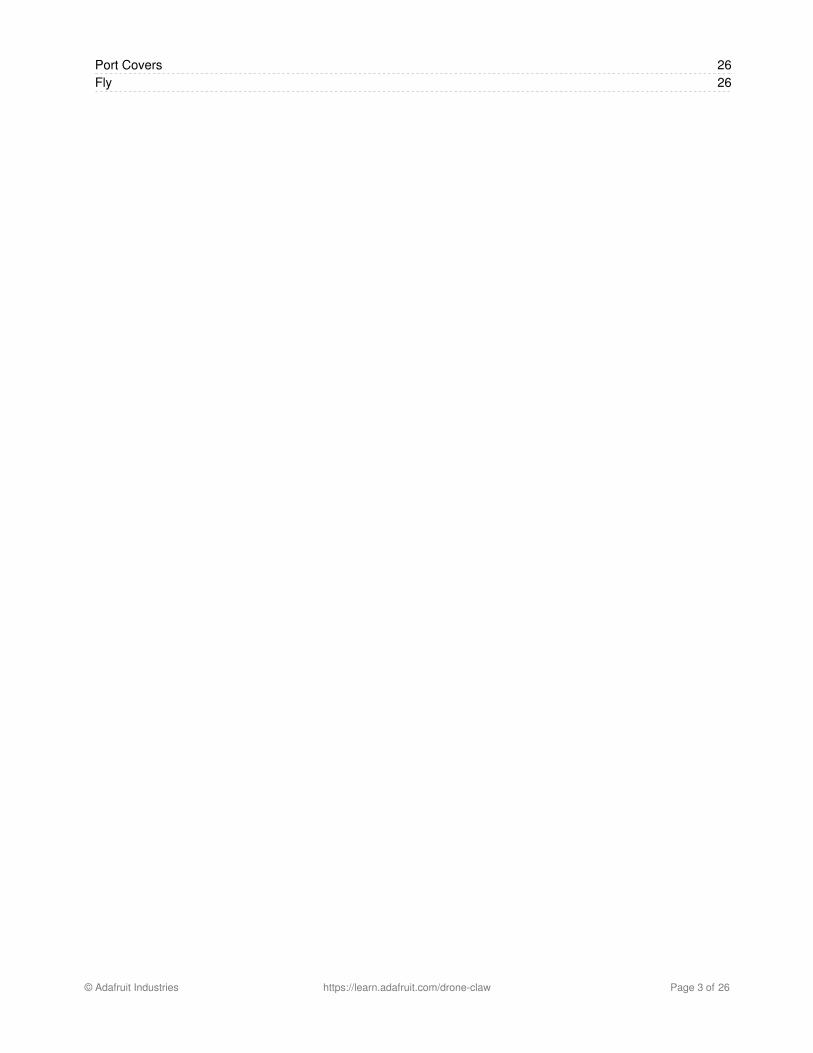
Connect wires to CPX
Instead of soldering, we can use three M3x6mm + nuts to connect the wires
to VOUT, A1 and GND.
Insert the screw from the top of the board and them attach the nut from the
bottom of the board. Use your finger or a screw driver to hold the screw in place
while attaching the nut.
Give the nut a turn or two, this way we'll have enough room to insert each wire.
Hook each wire to its pin and them use pliers to securely fasten each nut.
Position the wires as shown in the picture, this will make threading wires through
the enclosure easier later!
© Adafruit Industries https://learn.adafruit.com/drone-claw Page 14 of 26
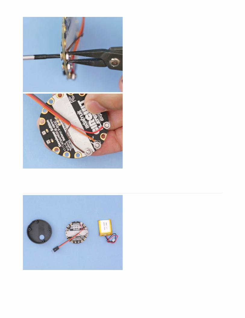
CPX case
Now we can move on to assembling the case. The case holds the Circuit
Playground Express board and the 500mah battery.
The standoffs have enough clearance to allow the battery to sandwich in between
the case and the CPX board.
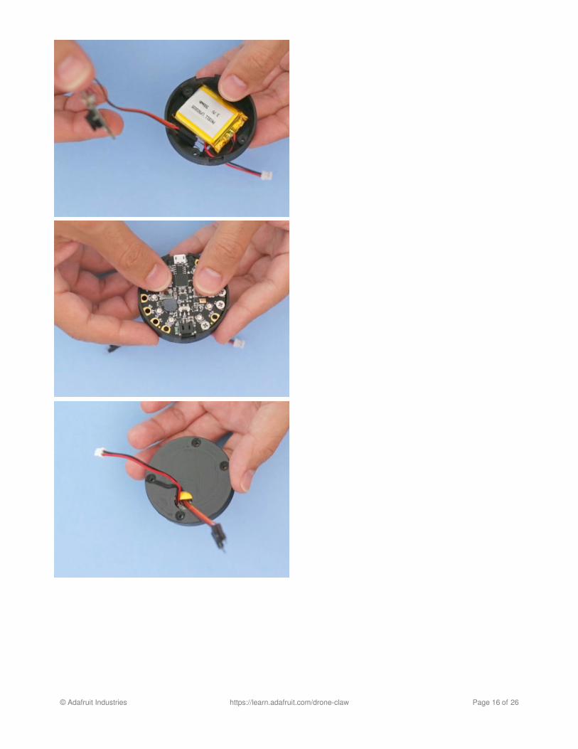
Lipo
First we'll lay the battery inside the case positioned as shown, with the
connections near the opening on the case. Pass the wires through the opening
and then insert the battery.
The CPX board lays over the battery. Align the board so the bigger cutaways can
align with the USB port.
© Adafruit Industries https://learn.adafruit.com/drone-claw Page 15 of 26
© Adafruit Industries https://learn.adafruit.com/drone-claw Page 16 of 26
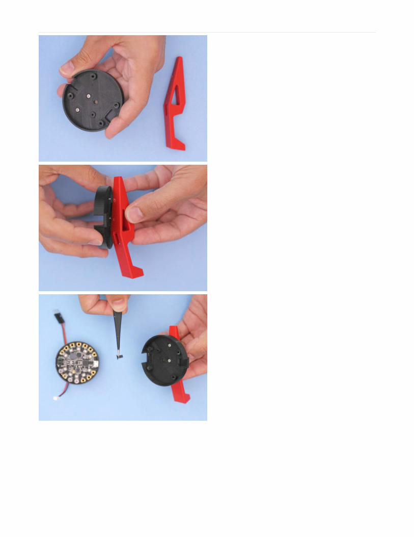
Cover + Leg
The cover is attached to the Left Leg part using two M2x5mm screws. Insert the
screws from inside between the standoffs. Fasten the two screws half in to help
create the threads for the screws.
Next we can align the protruding screws to the holes on the side of the Left Leg
part. Check that the mounting position is so that it leaves enough clearance on the
bottom of the leg.
Reset Button Extension
We designed a rest button part, so we could still access it while the CPX is inside
the enclosure. Insert the Reset Button between the standoffs, next to the light
pipe hole.
© Adafruit Industries https://learn.adafruit.com/drone-claw Page 17 of 26
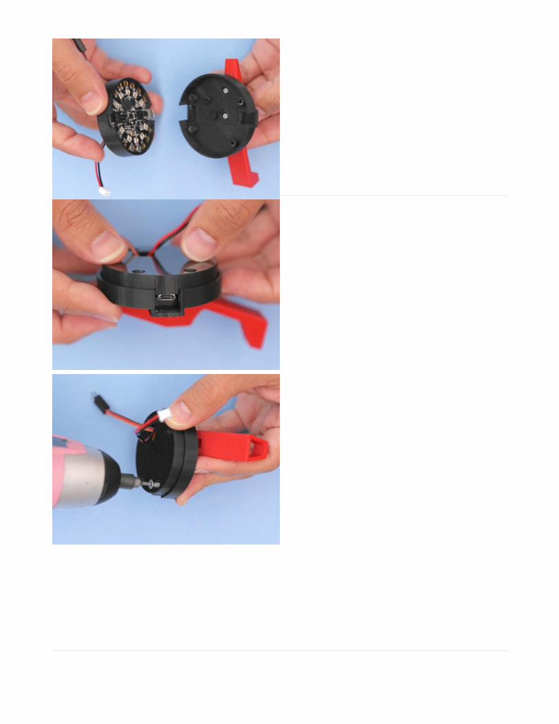
Align case
Position the case and cover over each other so the bigger port cutaway aligns with
USB port. Press fit the two parts and rotate them so both the JST and USB port
opening align.
Use tweezers to ensure the holes on the CPX board align with the standoffs on
both the case and cover.
With all of the holes aligned we can use a small drill to fasten the cover and case.
To reach through the enclosure and CPX board, we'll need two or four
M3x16mm screws.
© Adafruit Industries https://learn.adafruit.com/drone-claw Page 18 of 26
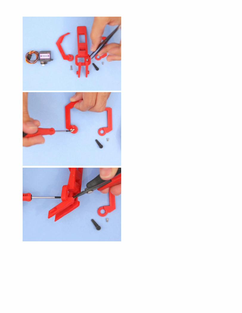
Leg Claw
Now we can move on to assembling the leg claw! First we'll prepare the Left Claw
part.
This part is driven by the rotation of the Right Claw. To stop the claw from getting
loose, we'll need to add a lock nut or a threaded insert to keep the screws from
unfastening itself.
Use tweezers to help position the the threaded insert inside the Leg Claw part.
The Left Claw will use one M3x6mm + threaded insert. Insert the screws until it
sits inside the grove above the gear teeth.
Align the Left Claw to the threaded insert. We used flat pliers to hold the threaded
insert in place while fastening the M3 screw. Don't tighten it all the way, leave a bit
slack so the claw can freely rotate.
© Adafruit Industries https://learn.adafruit.com/drone-claw Page 19 of 26
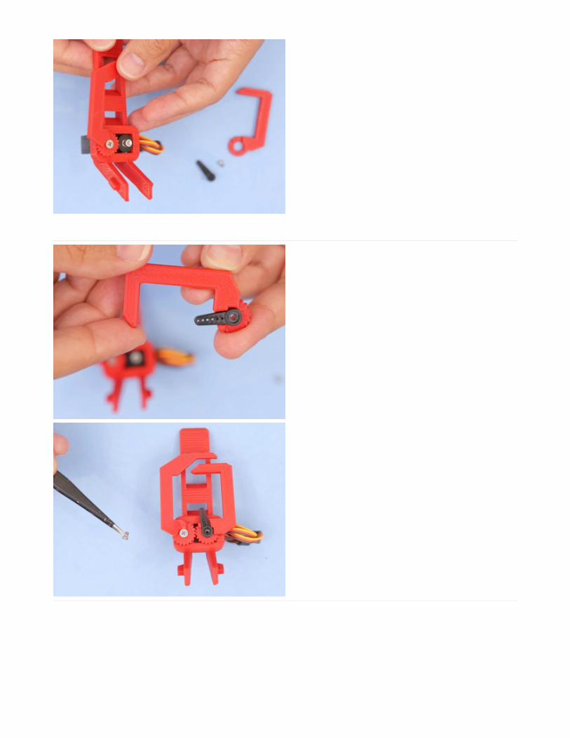
Right Claw - Servo Horn
The servo horn tightly press fits into Right Claw part, and is then secured with the
included M2.5x5mm screw.
First, we'll want to align the gears of the claws so they are both at the close
position as shown in the picture.
Carefully rotate the horn until you feel where the gear teeth insert into the servo
and then press fit the horn into the servo.
Test the close position by connecting the CPX to verify both claws align when
opened and closed. Modify by moving the claw until the gears both align to the
closed position.
© Adafruit Industries https://learn.adafruit.com/drone-claw Page 20 of 26
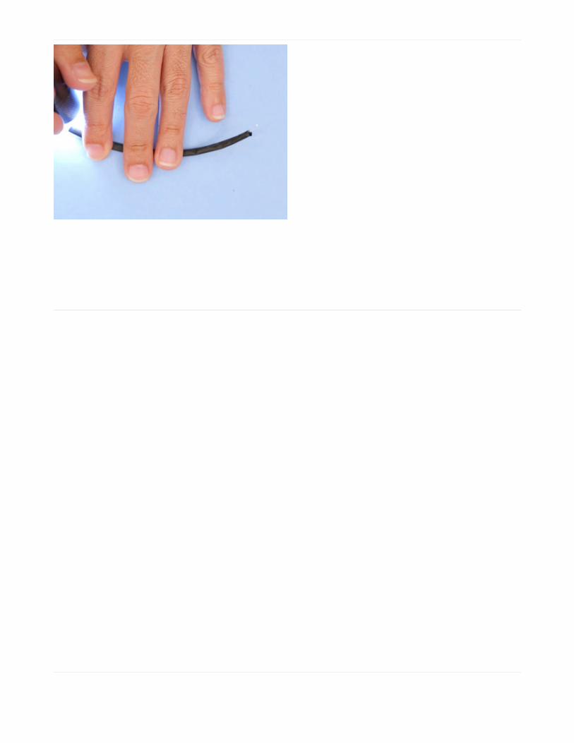
Prep Light Pipe
To prevent light leaking into the sensor, we'll need to cover the sides of the PETT
filament by painting, plastic dipping or using a sheathing like a heat shrink tube.
We measured a heat shrink tube 130mm long and inserted it over the PETT
filament.
Leg Install
With the CPX case and leg claw parts assembled, we can move on to installing the
components.
© Adafruit Industries https://learn.adafruit.com/drone-claw Page 21 of 26

Leg Claw Install
The two tabs on the Leg Claw part are attached to a tapered support to allow it to slightly bend. Apply a small amount of pressure to squeeze the supports to allow thetabs to fit inside of the slotted feet on the Mavic.
Front Legs
Rotate the leg parts so they align with shape of the Mavic legs. Make sure to clean
and remove any overhangs left over after printing, as it could block the legs from
fully seating into the parts.
Wire clip
The wires are held in place with the Wire clip part. The clip secures the servo
wires to the side of the Mavics body, away from the sensors and propellers.
© Adafruit Industries https://learn.adafruit.com/drone-claw Page 22 of 26
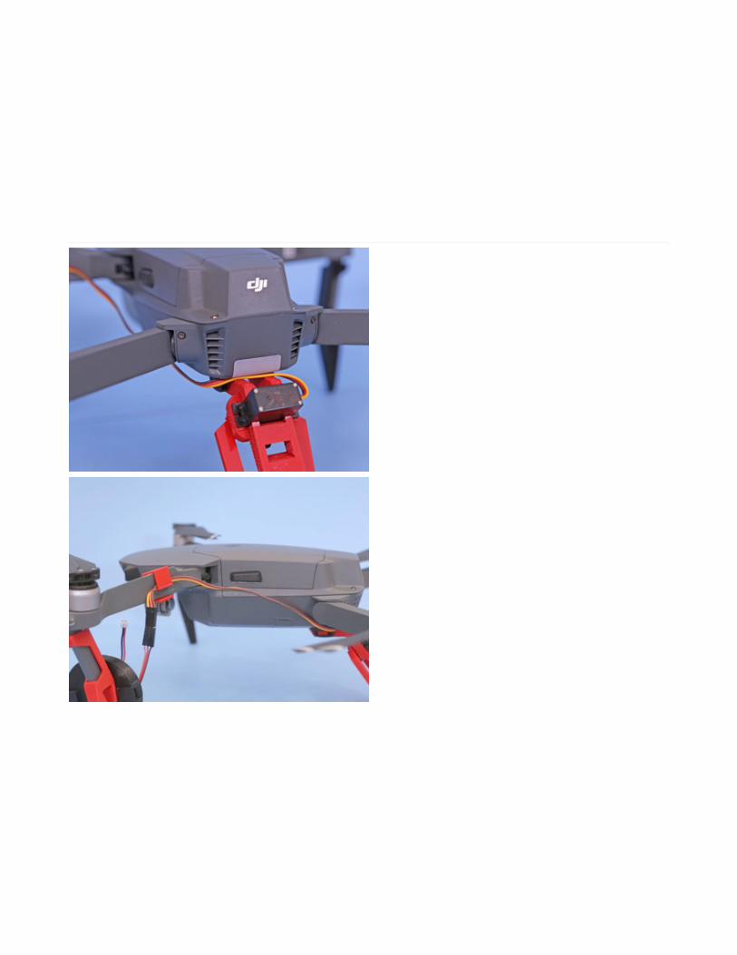
Attach wire clip
Route the wires as shown in the picture. The Leg Claw part has a bit of slack to
allow the cable to sit underneath the LED on the back of the Mavics body.
Pull the wire taut against the Mavics body to ensure the wires are away from the
propellers and the sensors.
Connect Jumper wires
Now we can go ahead and connect the servo wires to the Circuit Playground
Express. Align the jumper wires and press them together until they are full
connected.
Wire Slack TuckYou can insert any wire slack into the wire port opening on the enclosure.
© Adafruit Industries https://learn.adafruit.com/drone-claw Page 23 of 26
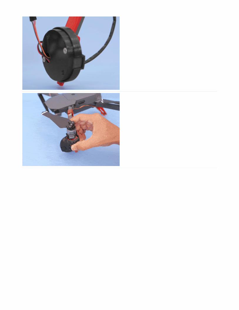
LED Cover Clip
To attach the PETT light pipe, we'll snap fit the LED Cover part onto the LED on
the Mavics front propeller mount. Make sure you clean any retraction bits around
the part and test fit inserting the light pipe into the clip before mounting.
Make sure the heat shrink completely covers the light pipe. If any light sources hit
the light pipe it could trigger the sensor on the Circuit Playground.
Port Covers
The JST and USB covers are 3d printed in NinjaFlex Cheetah (https://adafru.it/BkQ). This allows them to bend around wires and tightly fit around the enclosure to block outlight.
The USB cover slides into place from the bottom of the Cover part. Two grooves on the sides will allow the cover to slip into place.
The JST cover will first attach to the cable. Slip the JST wires through the slit and then press fit the cover into the port after you've plugged in the JST connection into theCircuit Playground Express.
Fly
That's it! Now we'll double check that all of the components are secured, wires are away from the sensors and do a final check of the gears on the claws. You can continueto modify the code by removing the USB cover and connecting to you device. Once you have verified everything functions as expected, we are ready for lift off!
© Adafruit Industries https://learn.adafruit.com/drone-claw Page 24 of 26

© Adafruit Industries https://learn.adafruit.com/drone-claw Page 25 of 26


