TIMES FIBER COMMUNICATIONS, INC. ® DROP CABLE SERIES Pictured is T10 Drop Cable, Quadshield version showing a complete drop cable construction including Times' exclusive lifeTime™ protectant. DIELECTRIC Closed cell, high velocity precision matrix foamed polyethylene which provides optimum dielectric hardness. The foam is bonded to the center conductor with a clean stripping, proprietary moisture-blocking polymer. Attenuation remains stable from 0% to 100% relative humidity. MESSENGER PVC jacketed, galvanized steel wire integrally attached to cable jacket with easily separable PVC web (see note under Jacket) serves as support for cable. CENTER CONDUCTOR Copper-clad steel or solid copper THIRD OUTER CONDUCTOR Unsealed aluminum-polypropylene- aluminum (APA) laminated tape, in conjunction with the second shield, provides an additional shield for improved signal isolation. SECOND OUTER CONDUCTOR Standard coverage aluminum alloy wire braids improve shielding ability and provide additional mechanical strength. FIRST OUTER CONDUCTOR Sealed aluminum-polypropylene-aluminum (APA) laminated tape longitudinally wrapped with an overlap around the dielectric to provide 100% coverage of the dielectric and long-term reliability of shielding performance. FOURTH OUTER CONDUCTOR Aluminum alloy wire braids, in conjuction with the first braids, sandwiches the second tape assuring good metallic contact in the overlap of the tape. JACKET Protective PVC applied over the braid to environmentally seal the construction. Both black and non-black jackets are UV resistant and may be used outdoors. Note: Polyethylene jacket used on the 11 Series messengered versions using 0.109 inch (2.77mm) messenger wire, or by special request Polyethylene jackets are also available on underground drop cables. Contact customer service. DETAILS OF CONSTRUCTION AND MATERIAL CORROSION RESISTANT PROTECTANT (See further explanation under Features, p.36.) Aerial lifeTime™ is a dripless compound which remains functional over a temperature range of -40˚F to 190˚F (-40˚C to +90˚C). Underground Flooding compound having cold flow properties for self-healing of small jacket ruptures. www.multicominc.com [email protected]Toll Free: 800-423-2594 Order From: ®
Transcript
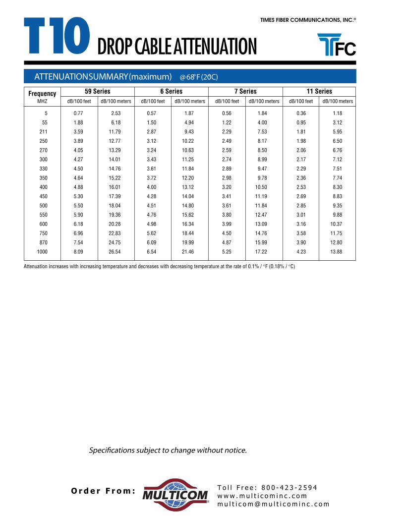
TIMES FIBER COMMUNICATIONS, INC.®
DROP CABLE SERIES
Pictured is T10 Drop Cable, Quadshield version showing a complete drop cable construction including Times' exclusive lifeTime™ protectant.
DIELECTRICClosed cell, high velocity precision matrixfoamed polyethylene which provides optimumdielectric hardness. The foam is bonded to thecenter conductor with a clean stripping,proprietary moisture-blocking polymer.Attenuation remains stable from 0% to 100%relative humidity.
MESSENGERPVC jacketed, galvanized steel wireintegrally attached to cable jacket witheasily separable PVC web (see note underJacket) serves as support for cable.
CENTER CONDUCTORCopper-clad steel orsolid copper
THIRD OUTER CONDUCTORUnsealed aluminum-polypropylene-aluminum (APA) laminated tape, inconjunction with the second shield,provides an additional shield for improvedsignal isolation.
SECOND OUTER CONDUCTORStandard coverage aluminum alloy wirebraids improve shielding ability and provideadditional mechanical strength.
FIRST OUTER CONDUCTORSealed aluminum-polypropylene-aluminum(APA) laminated tape longitudinallywrapped with an overlap around thedielectric to provide 100% coverage of thedielectric and long-term reliability ofshielding performance.
FOURTH OUTER CONDUCTORAluminum alloy wire braids, in conjuction withthe first braids, sandwiches the second tapeassuring good metallic contact in the overlapof the tape.
JACKETProtective PVC applied over the braid to environmentally sealthe construction. Both black and non-black jackets are UVresistant and may be used outdoors.Note: Polyethylene jacket used on the 11 Series messengered versionsusing 0.109 inch (2.77mm) messenger wire, or by specialrequest Polyethylene jackets are also available on underground dropcables. Contact customer service.
DETAILS OF CONSTRUCTION AND MATERIAL
CORROSION RESISTANT PROTECTANT(See further explanation under Features, p.36.)AeriallifeTime™ is a dripless compound whichremains functional over a temperature rangeof -40˚F to 190˚F (-40˚C to +90˚C).UndergroundFlooding compound having coldflow properties for self-healing of smalljacket ruptures.
www .m u l t i c o m i n c . c omm u l t i c o m@mu l t i c o m i n c . c om
T o l l F r e e : 8 0 0 - 4 2 3 - 2 5 9 4O r d e r F r om :®
T10TIMES FIBER COMMUNICATIONS, INC.®
FEATURES AND BENEFITS
DROP CABLE SERIES
The T10 Drop Cable Series is designed with reducing system operating costs in mind. The construction types offered in thisseries can be used in a variety of applications which can facilitate smooth system operation.
NECTFC manufactures CATV and CATVR drop cablesthat are NEC compliant. These cables are listed byUnderwriter’s Laboratories , (File #E86650) andmeets the requirements of National Electric Code(NEC), Article 820, Community Antenna Televisionand Radio Distribution Systems.
In addition to requirements governing variousinstallation methods and materials, the code sets forthdifferent levels of fire, flame, or smoke performancefor communication cables.
For more information, refer to Technical Note NEC#1044B.
BONDINGThe bonded construction of drop cable beginswith the center conductor to dielectric interfaceand continues from the dielectric to the tape.
A bonded center conductor serves as a guardagainst moisture ingress, defending againstcorrosion. In addition, the bonded dielectric,which prevents center conductor movement,facilitates connectorization by removing cleanlyand easily. Finally, bonding of the dielectric totape allows the overlapping tape to stay sealedduring cable flexure, minimizing RF signalingress/egress.
1 GHz BANDWIDTHT10 drop cable is specified to have SRL sweepperformance to 1 GHz. Specifying 1 GHzbandwidth for rebuilds, upgrades or new plantallows a system to handle future increasingcapacity needs demanded by more channels,higher definition television and other emergingtechnologies.
FLOODING COMPOUNDRecommended for burial cable applications,flooding compound is designed to provideadditional internal corrosion protection. Floodingcompound primarily prevents moisture ingressby flowing into any small area of jacket damage,acting as a self-healer.
TFC 's burial flooding compound for drop cable isa low viscous material that allows the compoundto flow readily into the crevices of the cablesouter braid and onto the taped outer conductor.
In addition to required viscosity and flowproperties, flooding compounds are chosen forcompatibility with the cable materials used andfor overall chemical, oxidation and UV resistanceproperties. Flooding materials are alsocompounded for high tackiness to aluminum,polyethylene and PVC to ensure uniform andcontinuous material protection.
lifeTime™Available exclusively from TFC, lifeTime™ isa corrosion resistant protectant designed to forma barrier against moisture ingress and retardcorrosion. A stable slightly tacky composition,lifeTime™ is applied to the aluminum braidand underlying tape. It does not drip and retainsits consistency through a wide range oftemperatures. lifeTime™ is used from the poleto the groundblock, is suitable for indoor usefrom the groundblock to the television set, andcan solve problems related to remote dcpowering such as interdiction.
The standard drop cable choice for manysystem operators, lifeTime™ drop cableoffers actual dollar saving benefits. Protectingagainst corrosion not only extends cable life, italso maintains performance. This meansimproved return on labor and materialinvestment while minimizing maintenancecosts as the system ages.
www .m u l t i c o m i n c . c omm u l t i c o m@mu l t i c o m i n c . c om
T o l l F r e e : 8 0 0 - 4 2 3 - 2 5 9 4O r d e r F r om :®
T10TIMES FIBER COMMUNICATIONS, INC.®
SINGLESingle drop cable is well-suited for a wide range of generalpurpose indoor and outdoor applications.
T10 Drop Cable Series offers a number of variations suited for different applications. Below is a listing which describes therecommended applications for each construction type. T10 Drop Cable Series is intended for applications from -40°F to +140°Fand its attenuation remains stable from 0% to 100% relative humidity.
APPLICATION OF CONSTRUCTION TYPES
DROP CABLE SERIES
MESSENGEREDMessengered cable is recommended for longer spans when higherstrength is required to improve reliability in severe weather conditions.A galvanized steel messenger wire is integrally joined to the coaxial cableby an an overall extruded jacket and connecting web.
• POLE-TO-HOUSEA high, flex-life messenger wire is utilized making it ideal for wrappingaround span clamps and “P” hooks. The wire can be easily cut forinstallation purposes and has superior break strength compared to otherversions available in similar sizes. Messenger sizes vary; refer to specifications.
• POLE-TO-POLEAn extra high strength 0.109 inch (2.77mm) wire with an 1800 pound (8007N) break strength is used for clearancecontrol between power and telephone cables and for resistance to heavy loading such as ice, wind and other hazardousconditions.
SIAMESETwo single cables are joined by an overall extruded PVC jacket andconnecting web for use in apartments and dual plant systems since it ismore economical to install one siamese cable than two single cables.
Note: Only available in 59 and 6 Series.
SIAMESE MESSENGEREDA PVC jacketed, galvanized steel wire is integrally attached to the jacketof the siamese cable by an extruded web. The wire acts as a support forthe cable in pole-to-house drops. Refer to MESSENGERED, Pole-to-House for an explanation of high flex-life wire.
www .m u l t i c o m i n c . c omm u l t i c o m@mu l t i c o m i n c . c om
T o l l F r e e : 8 0 0 - 4 2 3 - 2 5 9 4O r d e r F r om :®
T10TIMES FIBER COMMUNICATIONS, INC.®
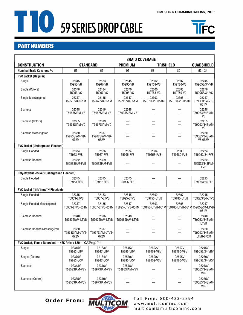
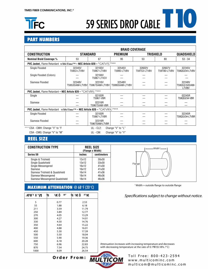
PART NUMBERS
TRISHIELD• Outer Conductor:
1. Sealed APA Laminated Tape2. Aluminum Braid3. APA Laminated Tape
• Braid Coverage Available:59 Series - 53% and 80%6 Series - 60% and 80%7 Series - 80%11 Series -60%
• High RF noise environment and two way applications.
QUADSHIELD• Outer Conductor:
1. Sealed APA Laminated Tape2. Inner Aluminum Braid3. APA Laminated Tape4. Outer Aluminum Braid
• Braid Coverage Available:59 Series - 53% Inner, 34% Outer6 Series - 60% Inner, 40% Outer7 Series - 60% Inner, 36% Outer11 Series - 53% Inner, 32% Outer11 Series - 60% Inner, 40% Outer
• Severe RF noise environment application, andtwo way applications.BRAID COVERAGE CALCULATIONS
BRAID COVERAGE DESCRIPTIONS
DROP CABLE SERIES
T10 Drop Cable is available in a wide selection of braid coverages. These coverage distinctions are designed to offer a choice of protectionfor a variety of environmental conditions. The descriptions below detail braid construction and environmental applications.
In addition to the 100% shielding coverage providedby internal shielding tapes, wire braid providesadditional shielding coverage. The percentage ofcoverage that a wire braid contributes is a function ofthe diameters of the wire braid and the underlyingstructure, the number of carriers (groups of wireends), the number of individual wires in each carrierand the picks per inch (the points of crossing of thecarriers). The following formulae are applicable:
ENDS
CARRIER
STANDARD• Outer Conductor:
1. Sealed APA Laminated Tape2. Aluminum Braid
• Braid Coverage Available:59 Series - 53% and 67%6 Series - 60%7 Series - 60%11 Series - 53% and 60%
• Low-medium RF noise environment application
PREMIUM• Outer Conductor:
1. Sealed APA Laminated Tape2. Aluminum Braid
• Braid Coverage Available:59 Series - 95%6 Series - 90%7 Series - 76%11 Series - 60%
• Medium-moderately high RF noise environment application
Percent Coverage = (2F - F2) x 100
Where: F = NPd/Sin AA = Tan -1 2 π (D + 2d) (P/C)
And: C = Number of carriers (groups of ends)N = Number of ends (strands) per carrierP = Picks per inch (carrier crossing points)d = Diameter of individual wire strand (inch)D = Diameter of structure under the braid (inch)
PICKS
www .m u l t i c o m i n c . c omm u l t i c o m@mu l t i c o m i n c . c om
T o l l F r e e : 8 0 0 - 4 2 3 - 2 5 9 4O r d e r F r om :®
DIELECTRICFoamed polyethylene produced by gasinjection in combination with proprietarynucleating agents and enhanceddimensional uniformity to meet 1 GHzrequirements. Federal specifications LP-390 and ASTM D-1248 are applicableto the polyethylene prior to thefoaming.
Not Shown:MESSENGER •T10 Semiflex: Galvanized 0.109 inch (2.77mm) solid steel wire (ASTM A-326), galvanized 0.188 inch (4.78mm) or 0.250 inch
(6.35 mm) stranded steel wire (ASTM A-475).
•TX10 Semiflex: Galvanized 0.188 inch (4.78mm) or 0.250 inch (6.35 mm) stranded wire (ASTM A-475).
Pictured: T10 Semiflex Cable, Armored, with flooding compound
JACKET*Abrasion resistant, low coefficient of frictionmedium density black polyethylene (FederalSpecification LP-390 and ASTM D-1248jacketing material).* Sequential footage marking on outer jacketavailable upon request. Standard onunderground, flooded cables.
• NON-FLOWINGIntended for aerial applications, non-dripping flooding compound.
SEMIFLEX CABLE SERIES
Extra thick jacket is also available.
ARMORA 0.010 inch thick steel tape per SAE/AISI 1010for steel.
DIELECTRIC ADHESIVE COATINGProprietary polymer adhesive coating to bond core toouter conductor for improved handling and strengthcharacteristics in cold weather.
OUTER CONDUCTORSeamless high purity electrical grade aluminumtube. (ASTM B-221).
www .m u l t i c o m i n c . c omm u l t i c o m@mu l t i c o m i n c . c om
T o l l F r e e : 8 0 0 - 4 2 3 - 2 5 9 4O r d e r F r om :®
T10TIMES FIBER COMMUNICATIONS, INC.®
FEATURES AND BENEFITS
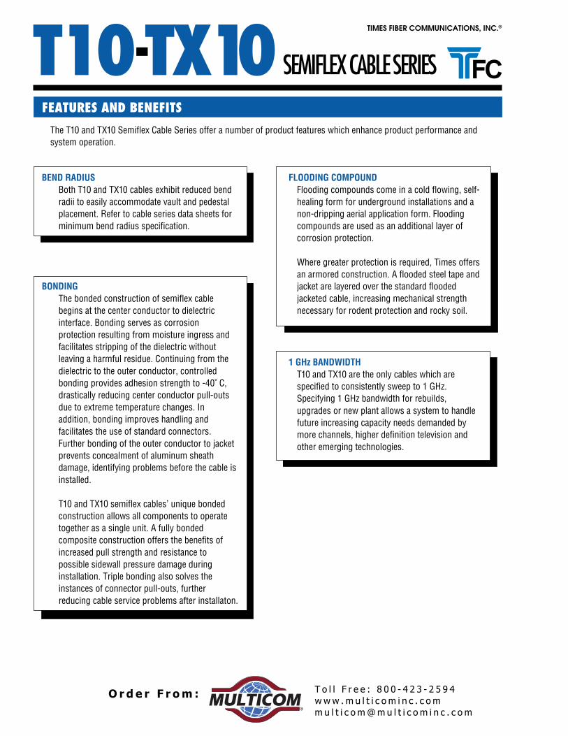
The T10 and TX10 Semiflex Cable Series offer a number of product features which enhance product performance andsystem operation.
BEND RADIUSBoth T10 and TX10 cables exhibit reduced bendradii to easily accommodate vault and pedestalplacement. Refer to cable series data sheets forminimum bend radius specification.
BONDINGThe bonded construction of semiflex cablebegins at the center conductor to dielectricinterface. Bonding serves as corrosionprotection resulting from moisture ingress andfacilitates stripping of the dielectric withoutleaving a harmful residue. Continuing from thedielectric to the outer conductor, controlledbonding provides adhesion strength to -40˚ C,drastically reducing center conductor pull-outsdue to extreme temperature changes. Inaddition, bonding improves handling andfacilitates the use of standard connectors.Further bonding of the outer conductor to jacketprevents concealment of aluminum sheathdamage, identifying problems before the cable isinstalled.
T10 and TX10 semiflex cables’ unique bondedconstruction allows all components to operatetogether as a single unit. A fully bondedcomposite construction offers the benefits ofincreased pull strength and resistance topossible sidewall pressure damage duringinstallation. Triple bonding also solves theinstances of connector pull-outs, furtherreducing cable service problems after installaton.
FLOODING COMPOUNDFlooding compounds come in a cold flowing, self-healing form for underground installations and anon-dripping aerial application form. Floodingcompounds are used as an additional layer ofcorrosion protection.
Where greater protection is required, Times offersan armored construction. A flooded steel tape andjacket are layered over the standard floodedjacketed cable, increasing mechanical strengthnecessary for rodent protection and rocky soil.
1 GHz BANDWIDTHT10 and TX10 are the only cables which arespecified to consistently sweep to 1 GHz.Specifying 1 GHz bandwidth for rebuilds,upgrades or new plant allows a system to handlefuture increasing capacity needs demanded bymore channels, higher definition television andother emerging technologies.
SEMIFLEX CABLE SERIES-T10 TX10
www .m u l t i c o m i n c . c omm u l t i c o m@mu l t i c o m i n c . c om
T o l l F r e e : 8 0 0 - 4 2 3 - 2 5 9 4O r d e r F r om :®
TIMES FIBER COMMUNICATIONS, INC.®
T10
Application: Where cable is exposed to extensive mechanical abuseand rodent attack, armored semiflex cable is recommended. Used fordirect burial applications, Armored semiflex cable features a floodedsteel tape and jacket which are layered over the standard floodedjacketed cable to increase mechanical strength.
ARMORED
JACKETED BURIAL
Application: Jacketed Burial semiflex cable is recommended forunderground applications in conduit or direct burial installations.This version features a cold flowing, self-healing flooding compoundfor underground applications, providing an additional layer ofcorrosion protection. For aerial applications, non-dripping floodingcompound is used which also serves as an additional layer ofcorrosion protection.
MESSENGEREDApplication: Messengered semiflex cable is recommended for aerialfeeder installations where strand installation is not practical. T10412and T10500 semiflex cable is designed with a strong, integral,galvanized solid steel wire which supports the cable in aerialinstallations. TX10625 and TX10565 semiflex cable features ajacketed galvanized stranded steel wire which also acts as a support,relieving the cable from undue tension. Resting ladders onmessengered cable is not recommended.
Application: Recommended for aerial installations in a non-corrosiveenvironment, unjacketed semiflex cable features bonding of thecenter conductor to the dielectric and dielectric to the outerconductor. This bonding prevents moisture ingress and facilitatesconnectorization since it leaves no harmful residue.
UNJACKETED
JACKETEDApplication: For aerial applications in urban and coastalenvironments, Jacketed semiflex cable is recommended wherehighly corrosive conditions may exist. This cable features a triplebonding of the center conductor to the dielectric, dielectric to theouter conductor and outer conductor to the jacket and is designedto withstand more abrasion and mechanical abuse than anunjacketed version. With an extra thick jacket, this cable willwithstand more abrasion and mechanical abuse than the standardjacketed burial cable.
SEMIFLEX CABLE SERIES -T10 TX10
www .m u l t i c o m i n c . c omm u l t i c o m@mu l t i c o m i n c . c om
T o l l F r e e : 8 0 0 - 4 2 3 - 2 5 9 4O r d e r F r om :®
T10TIMES FIBER COMMUNICATIONS, INC.®
CONSTRUCTION
CENTER CONDUCTORCopper-Clad Aluminum
Part Number MI NumberUnjacketed T10500 24500
Unjacketed, Tracer Coded T10500VI 24510
Jacketed T10500J 24501
Jacketed, Extra Thick Jacket T10500JX 24506
Jacketed, Extra Thick Jacket, Tracer Coded T10500JXVI 24516
Jacketed, Tracer Coded T10500JVI 24511
Jacketed Messengered T10500MS 24505
Jacketed Flooded, Underground T10500JB 24502
Jacketed Flooded, Underground, Extra Thick Jacket T10500JBX 24507
Jacketed Flooded, Underground, Extra Thick Jacket, Tracer Coded T10500JBXVI 24517
NEC - Article 820, CATV Listed, Unjacketed T10500V 24500V
*Used for aerial applications due to non-flowing, non-dripping compound.
Note: Standard colored tracer stripes are red, yellow, green, blue, white, and slate. For other color combinations,please contact a customer service representative or your area sales representative.
PART NUMBERS
500 SERIES SEMIFLEX CABLE
Jacketed Jacketed Burial
Unjacketed
Messengered Armored
www .m u l t i c o m i n c . c omm u l t i c o m@mu l t i c o m i n c . c om
T o l l F r e e : 8 0 0 - 4 2 3 - 2 5 9 4O r d e r F r om :®
NEC - Article 820, CATV V00642V52601TdetekcajnU ,detsiL
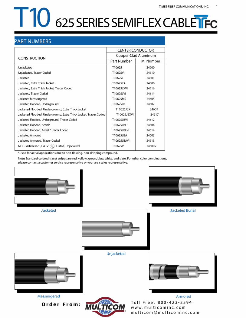
*Used for aerial applications due to non-flowing, non-dripping compound.
Note: Standard colored tracer stripes are red, yellow, green, blue, white, and slate. For other color combinations,please contact a customer service representative or your area sales representative.
PART NUMBERS
625 SERIES SEMIFLEX CABLE
lairuB detekcaJdetekcaJ
Unjacketed
Messengered Armored
www .m u l t i c o m i n c . c omm u l t i c o m@mu l t i c o m i n c . c om
T o l l F r e e : 8 0 0 - 4 2 3 - 2 5 9 4O r d e r F r om :®
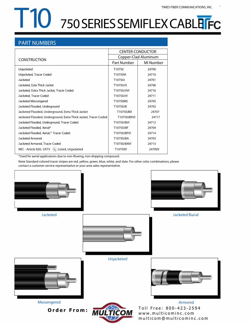
NEC - Article 820, CATV Listed, Unjacketed T10750V 24700V
*Used for aerial applications due to non-flowing, non-dripping compound.
Note: Standard colored tracer stripes are red, yellow, green, blue, white, and slate. For other color combinations, pleasecontact a customer service representative or your area sales representative.
PART NUMBERS
750 SERIES SEMIFLEX CABLE
lairuB detekcaJdetekcaJ
Unjacketed
Messengered Armored
www .m u l t i c o m i n c . c omm u l t i c o m@mu l t i c o m i n c . c om
T o l l F r e e : 8 0 0 - 4 2 3 - 2 5 9 4O r d e r F r om :®
NEC - Article 820, CATV Listed, Unjacketed T10875V 24800V
*Used for aerial applications due to non-flowing, non-dripping compound.
Note: Standard colored tracer stripes are red, yellow, green, blue, white, and slate. For other color combinations,please contact a customer service representative or your area sales representative.
CONSTRUCTION
PART NUMBERS
875 SERIES SEMIFLEX CABLE
lairuB detekcaJdetekcaJ
Unjacketed
Messengered Armored
www .m u l t i c o m i n c . c omm u l t i c o m@mu l t i c o m i n c . c om
T o l l F r e e : 8 0 0 - 4 2 3 - 2 5 9 4O r d e r F r om :®
TIMES FIBER COMMUNICATIONS, INC.®
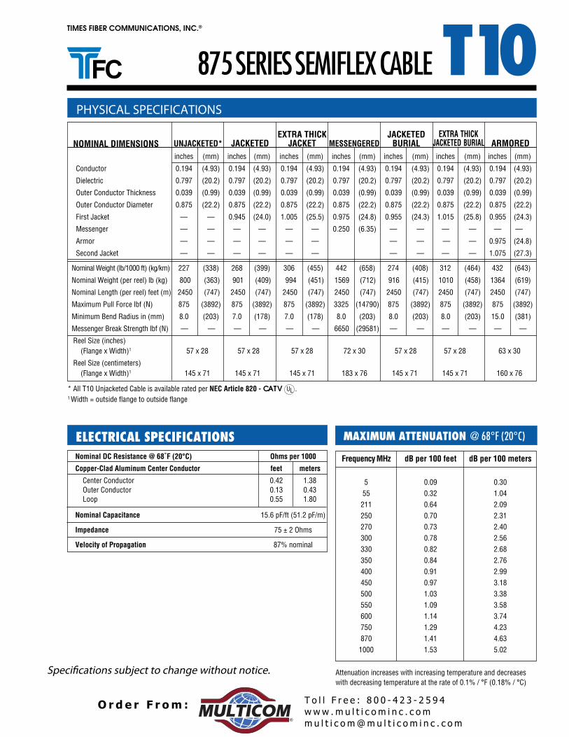
T10875 SERIES SEMIFLEX CABLE
ATTENUATION @ 68°F (20°C)
Nominal DC Resistance @ 68˚F (20°C) Ohms per 1000
Copper-Clad Aluminum Center Conductor feet meters
Center Conductor 0.42 1.38 Outer Conductor 0.13 0.43
*Used for aerial applications due to non-flowing, non-dripping compound.
Note: Standard colored tracer stripes are red, yellow, green, blue, white, and slate. For other color combinations,please contact a customer service representative or your area sales representative.
565 SERIES SEMIFLEX CABLE
www .m u l t i c o m i n c . c omm u l t i c o m@mu l t i c o m i n c . c om
T o l l F r e e : 8 0 0 - 4 2 3 - 2 5 9 4O r d e r F r om :®
*Used for aerial applications due to non-flowing, non-dripping compound.
Note: Standard colored tracer stripes are red, yellow, green, blue, white, and slate. For other colorcombinations, please contact a customer service representative or your area sales representative.
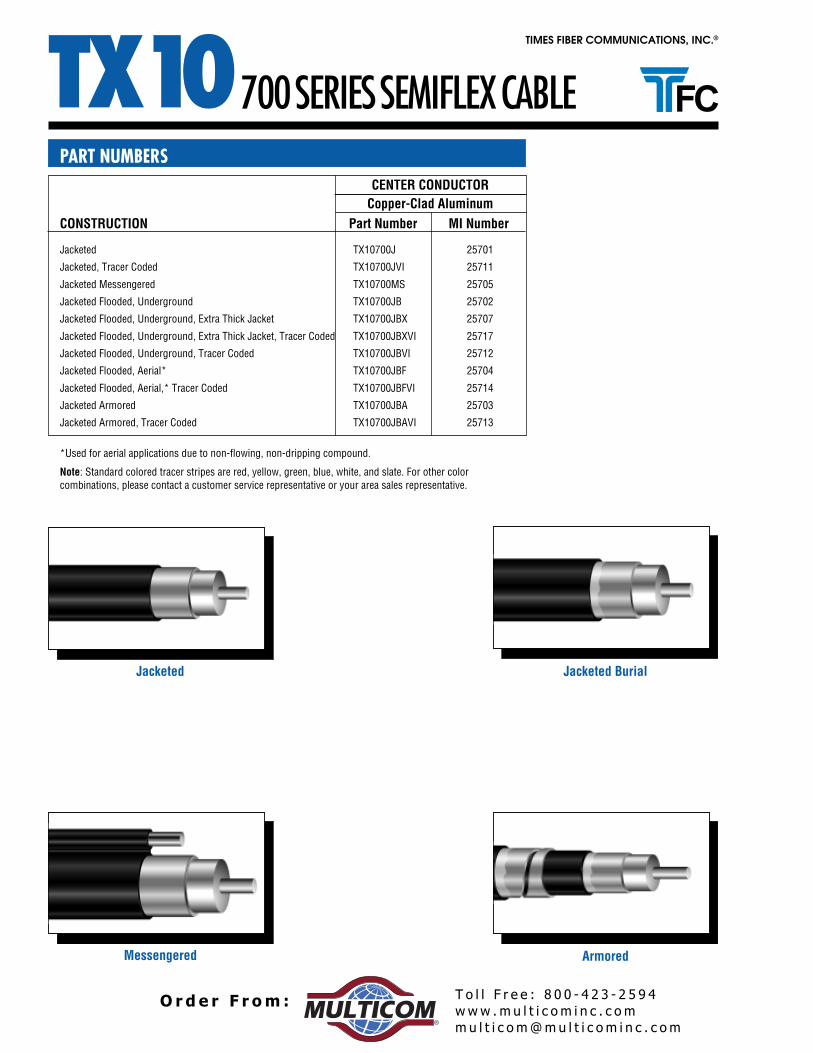
PART NUMBERSCENTER CONDUCTOR
Copper-Clad Aluminum
700 SERIES SEMIFLEX CABLE
Jacketed Jacketed Burial
Messengered Armored
www .m u l t i c o m i n c . c omm u l t i c o m@mu l t i c o m i n c . c om
T o l l F r e e : 8 0 0 - 4 2 3 - 2 5 9 4O r d e r F r om :®
• Center Conductor - Silver-plated copper-clad steel forlong term low contact resistance, low attenuation andaxial strength, with easy cable preparation and reliableconnector attachment for “F” type fittings.
• Dielectric - Foam Polyethylene, low loss, high velocityproviding optimum dielectric properties. The foam isbonded to the center conductor with an easily stripped,proprietary moisture-blocking polymer.
• Outer Conductor1. Sealed APA Laminated Tape2. 95% Aluminum Braid3. APA Laminated Tape4. 95% Aluminum Braid