Photo ]:A boiler room at Southern Connecticut State University. The control cabinets feature multiple loop controllers,vertical draft indica- tor, and a tank gage and leak detection system. By David Eoff T he crude oil peak price of $147 per barrel in July 2008 demonstrated that fuel oil prices going forward will be volatile and subject to extreme price spikes. Boiler owners and plant engineers need to understand boiler efficiency and what can be done to save fuel in the typical boiler room. Table I illustrates the amount of fuel a typical small boiler consumes, compared with the capital cost of the boiler, burner, and controls. The data in Table I are based on natural gas at $10 per MMBtu and heating oil at $3.63 per gallon ($0.97 per L). It becomes apparent that when operated at a 25% capacity factor, a boiler will consume at least twice its capital cost in fuel every year. An oil-fired boiler will consume at least four times its cost in fuel every year. Because of their relatively low capital cost and high impact on boiler efficiency, burner and combustion control retrofits offer boiler owners the quickest paybacks based on energy savings. 38 ASHRAE Journal Understanding Boiler Heat Losses To better understand the effect of burner and controls performance on efficiency, we need to have an under- standing of boiler heat losses. Using typical packaged boiler operating data, boiler efficiency calculated according to the American Society of Mechanical Engineers (ASME) PTC 4.1, Power Test Codes for Steam Generating Units, yields typical boiler losses (Table 2). ASME PTC 4.1 includes instructions for calculating boiler efficiency by the direct method comparing steam output versus heat input. It also calculates boiler efficiency by the indirect (by losses) method where individual boiler losses are calculated and totaled. The "by losses" method requires only stack temperature and oxygen content and can easily be calculated with a portable combustion analyzer or built into the combustion controls. ANSI Standard Z21.13 outlines efficiency calculations for hot water boil- ers. The loss mechanisms are similar. Table 3 details the equations used to cal- culate three of the largest boiler losses to illustrate how these losses can be affected by boiler/burner performance. The three equations in Table 3 for different boiler losses have several ele- ments in common, suggesting a com- mon strategy for reducing boiler losses, including: "* Reducing stack temperature; "• Minimizing excess air levels; "• Raising boiler feedwater tempera- ture; and "• Raising combustion air tempera- ture to the burner. About the Author David Eoff is national sales manager at Preferred Utilities, Danbury, Conn. December 2008 ashrae.org
Transcript
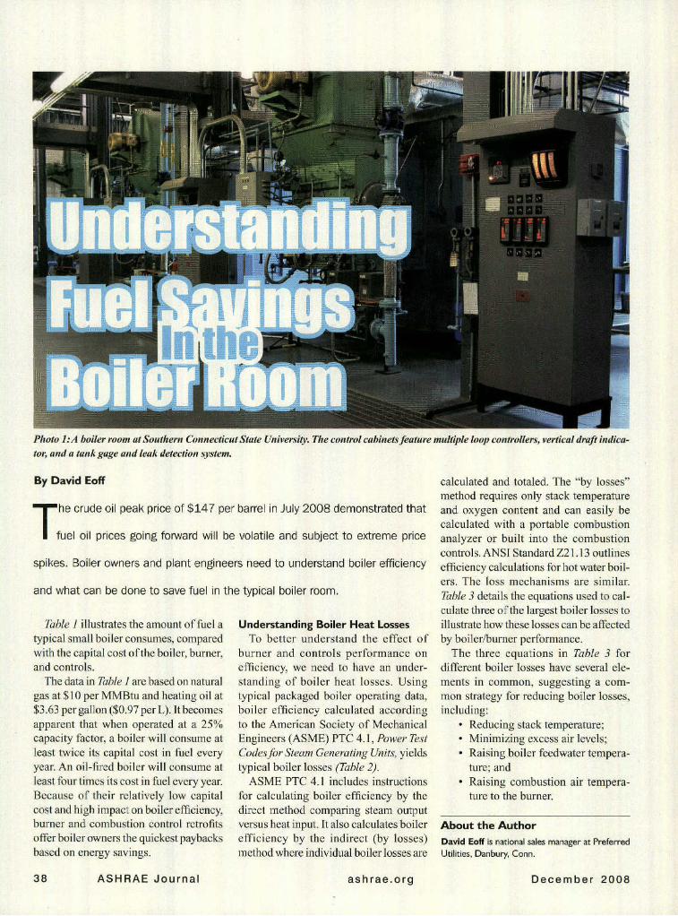
Photo ]:A boiler room at Southern Connecticut State University. The control cabinets feature multiple loop controllers, vertical draft indica-
tor, and a tank gage and leak detection system.
By David Eoff
T he crude oil peak price of $147 per barrel in July 2008 demonstrated thatfuel oil prices going forward will be volatile and subject to extreme price
spikes. Boiler owners and plant engineers need to understand boiler efficiency
and what can be done to save fuel in the typical boiler room.
Table I illustrates the amount of fuel atypical small boiler consumes, comparedwith the capital cost of the boiler, burner,and controls.
The data in Table I are based on naturalgas at $10 per MMBtu and heating oil at$3.63 per gallon ($0.97 per L). It becomesapparent that when operated at a 25%capacity factor, a boiler will consume atleast twice its capital cost in fuel everyyear. An oil-fired boiler will consume atleast four times its cost in fuel every year.Because of their relatively low capitalcost and high impact on boiler efficiency,burner and combustion control retrofitsoffer boiler owners the quickest paybacksbased on energy savings.
38 ASHRAE Journal
Understanding Boiler Heat LossesTo better understand the effect of
burner and controls performance onefficiency, we need to have an under-standing of boiler heat losses. Usingtypical packaged boiler operating data,boiler efficiency calculated accordingto the American Society of MechanicalEngineers (ASME) PTC 4.1, Power TestCodes for Steam Generating Units, yieldstypical boiler losses (Table 2).
ASME PTC 4.1 includes instructionsfor calculating boiler efficiency by thedirect method comparing steam outputversus heat input. It also calculates boilerefficiency by the indirect (by losses)method where individual boiler losses are
calculated and totaled. The "by losses"method requires only stack temperatureand oxygen content and can easily becalculated with a portable combustionanalyzer or built into the combustioncontrols. ANSI Standard Z21.13 outlinesefficiency calculations for hot water boil-ers. The loss mechanisms are similar.Table 3 details the equations used to cal-culate three of the largest boiler losses toillustrate how these losses can be affectedby boiler/burner performance.
The three equations in Table 3 fordifferent boiler losses have several ele-ments in common, suggesting a com-mon strategy for reducing boiler losses,including:
About the AuthorDavid Eoff is national sales manager at PreferredUtilities, Danbury, Conn.
December 2008ashrae.org
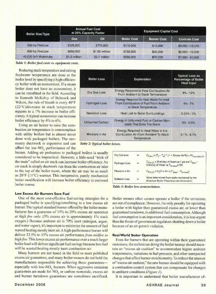
Table 1: Boiler fuel costs vs. equipment costs.
Reducing stack temperature and raisingfeedwater temperature are done at theboiler level by specifying a high-efficien-cy boiler with an economizer. If a steamboiler does not have an economizer, itcan be retrofitted in the field. According Dry Gas Lossto Kenneth McKelvy of Babcock andWilcox, the rule of thumb is every 407 yroeFLs(22°C)decrease in stack temperatureequates to a 1% increase in boiler effi- Radiation Lossciency. A typical economizer can increaseboiler efficiency by 4% to 6%.
Using an air heater to raise the com-bustion air temperature is commonplacewith utility boilers but is almost never Moisture in Airdone with packaged boilers. The nec-essary ductwork is expensive and can Table 2: Typical boile,affect the low-NOx performance of theburner. Adding air preheaters to packaged boilers is usuallyconsidered to be impractical. However, a little-used "trick ofthe trade" called an air stack can increase boiler efficiency. Anair stack is simply ductwork run from the combustion air inletto the top of the boiler room, where the air may be as muchas 20'F (1 PC) warmer. This inexpensive, purely mechanicalboiler modification will increase boiler efficiency in enclosedboiler rooms.
Low Excess Air Burners Save FuelOne of the most cost-effective fuel-saving strategies for a
packaged boiler is specifying/retrofitting to a low excess airburner. The typical standard burner offered by the boiler manu-facturer has a guarantee of 15% to 20% excess air operationat highfire only. (5% excess air is approximately 1% stackoxygen.) Because ambient air is 79% inert (nitrogen, argon,and water vapor), it's important to minimize the amount of fuelwasted heating mostly inert air. A high-performance burner willdeliver 12.5% to 15% excess air performancefrom midfire tohighfire. This lower excess air performance over a much largerboiler load will deliver significant fuel savings because less fuelwill be wasted heating mostly inert combustion air.
Many burners are not tuned in the field to meet publishedexcess air guarantees, and many boiler owners do not hold themanufacturers responsible for achieving these guarantees-especially with low-NOx burners. When aggressive emissionguarantees are made for NO, or carbon monoxide, excess airand burner turndown guarantees are sometimes sacrificed.
-.II
r losses.
Dry Gas Loss = Cp(,) x (Ts- TA) * (I + Excess Air%) x MTh-tical Air
Hydrogen Loss = CP(Ho) x (Enthalpy of Steam at I psi and Ts,tk -Enthalpy of Water at TA,biwt)/ 100
Moisture in Air - CP(H,o) x H 2 0 in Air x (Tstck - TAmbient)
Radiation Loss = Value determined from table maintained by theAmerican Boiler Manufacturers Association
Table 3: Boiler loss nomenclature.
Boiler owners often cannot operate a boiler if the emissionsare out of compliance. However, the only penalty for operatinga boiler with higher than guaranteed excess air, or lower thanguaranteed turndown, is additional fuel consumption. Althoughfuel consumption is an important consideration, it is less urgentthan the threat of government regulators shutting down a boilerbecause of an air permit violation.
Real-World Boiler OperationEven for burners that are operating within their guaranteed
emissions, the technician doing the boiler tuneup should main-tain an "excess air cushion" to accommodate higher ambienttemperatures, variations in fuel pressure, and other unexpectedchanges that affect burner stoichiometry. To reduce the amountof "excess air cushion," the new burner should be equipped witha combustion control system that can compensate for changesin ambient conditions (Figure 1).
It is important to understand that boiler manufacturer ef-
ASHRAE Journal 39December 2008
DrumPressure
PT
EJackshaftActuator
Firing Rate
Oil 0.
Gas P-
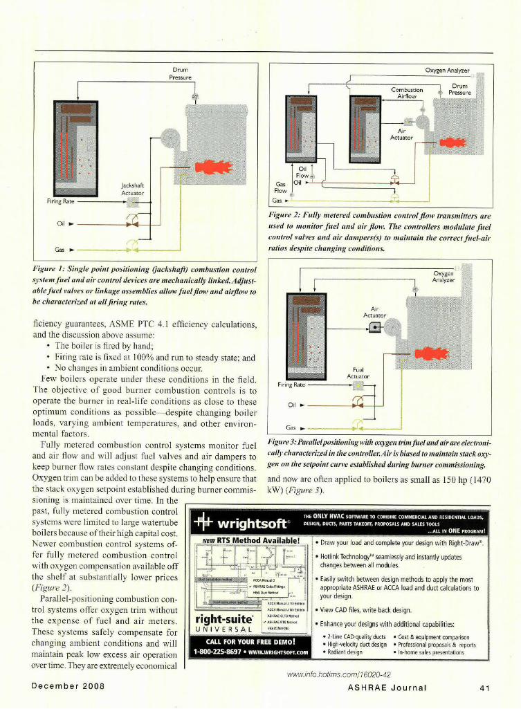
Figure 1: Single point positioning Oackshaft) combustion controlsystem fuel and air control devices are mechanically linked. Adjust-able fuel valves or linkage assemblies allow fuel flow and airflow tobe characterized at allfiring rates.
"* The boiler is fired by hand;"* Firing rate is fixed at 100% and run to steady state; and"* No changes in ambient conditions occur.
Few boilers operate under these conditions in the field.The objective of good burner combustion controls is tooperate the burner in real-life conditions as close to theseoptimum conditions as possible--despite changing boilerloads, varying ambient temperatures, and other environ-mental factors.
Fully metered combustion control systems monitor fueland air flow and will adjust fuel valves and air dampers tokeep burner flow rates constant despite changing conditions.Oxygen trim can be added to these systems to help ensure thatthe stack oxygen setpoint established during burner commis-sioning is maintained over time. In thepast, fully metered combustion control
systems were limited to large watertubeboilers because of their high capital cost.Newer combustion control systems of-fer fully metered combustion control 4. .
with oxygen compensation available offthe shelf at substantially lower prices(Figure 2).
Parallel-positioning combustion con-trol systems offer oxygen trim withoutthe expense of fuel and air meters. right-suiteWThese systems safely compensate for u N I V E R S A Lchanging ambient conditions and will 1 O I
maintain peak low excess air operation . ..over time. They are extremely economical
December 2008
Figure 2: Fully metered combustion control flow transmitters are
used to monitor fuel and airflow. The controllers modulate fuelcontrol valves and air dampers(s) to maintain the correct fuel-air
ratios despite changing conditions.
Figure 3: Parallelpositioning with oxygen trim fuel and air are electroni-cally characterized in the controller.Air is biased to maintain stack oxy-gen on the setpoint curve established during burner commissioning.
and now are often applied to boilers as small as 150 hp (1470kW) (Figure 3).
mvaliiagme! Draw your load and complete your design with Right-Draw".
S•f Hotlink TechnologyTM seamlessly and instantly updateschanges between all modules.
". 1 * Easily switch between design methods to apply the mosteM.xF I" appropriate ASHRAE or ACCA load and duct calculations to
Burner Turndown Affects EfficiencyBurner turndown is important for
fuel savings-especially during low-load conditions. The typical burneris designed for 6:1 turndown firingnatural gas and 4:1 turndown firingoil (6:1 turndown means high-fire fuelflow is six times low-fire fuel flow).In practice, many burners operate at3:1 turndown-meaning they light offat 33% of high-fire heat input. If 33%firing rate produces more steam (or hotwater) than the plant load, the burnereventually shuts down on high steampressure or high water temperature, andall the losses associated with post purge,standby and purge are incurred again.Frequent boiler cycling also introducesthermal shock to the boiler tubes andrefractory to shorten boiler life.
Because boilers tend to be oversized(typically 5% for every engineer whotouches the design), it is common forboilers to cycle on and off during low-load conditions. Each time a boiler cyclesoff, it drafts cold combustion air duringthe post purge and standby periods. Whenthe boiler is cycled on again, it must gothrough a purge period when more coldair is cycled through the boiler to purgethe furnace ofpossible combustibles priorto ignition. All the heat lost to this coldair has to be recouped by the burner whenit lights off again. It is not uncommon tosee small boilers cycle up to 10 times perhour during low-load periods.
A high-performance burner will oper-ate safely at 10:1 turndown on gas and8:1 turndown on oil. A turndown ratioof 10:1 means low-fire heat input is just10% of high-fire heat input. A high-turndown burner is much more likelyto stay on during low-load conditionsand not incur all the cycling losses of atypical burner.
To determine boiler turndown, putthe boiler in manual firing rate, lock itat high fire, and clock the fuel meter.Repeat the procedure with the burner atlow fire. Divide the high-fire fuel flowby the low-fire fuel flow. If the burnerdoesn't have a dedicated gas or oil meter,Bernoulli's equation provides a way toapproximate burner turndown when fir-
ing gas. Simply measure the gas manifoldpressure (downstream of the gas flowcontrol valve) at high fire, divide by thegas manifold pressure at low fire, andcalculate the square root. The number thatis left is the burner turndown.
Multiple Boiler PlantsFinally, multiple-boiler plants can save
additional fuel by installing a modernlead/lag controller. A typical systemmonitors one header pressure or tem-perature transmitter, operates the optimalnumber of boilers to meet the currentplant load, and fires the boilers at theirmost efficient firing rates to minimizefuel consumption.
When fuel prices were relatively inex-pensive, it was common to have one boilerrunning in automatic and a second boilerrunning at low fire in case the first boilertripped offline. A modem lead/lag control-ler will keep the lag boiler off, cycle it onoccasionally to keep it hot, and only bringit online if the lead boiler trips offline or isnot capable of handling the current plantload. Because steam and noncondensinghot water boilers are more efficient at highfire, a lead/lag controller will fire fewerboilers at the highest firing rate possible forhighest efficiency. Condensing boilers aremore efficient at low fire, so this strategyis reversed for condensing boilers.
With the high fuel prices in the U.S.,high-performance burners and controlsare inexpensive compared with the priceof fuel wasted by the typical boiler. Boilerowners who previously installed high-performance burners and combustioncontrols now can reap the benefits.
Because of fuel price volatility, the oldadage should apply: "Hope for the best,but plan for the worst."
BibliographyDukelow, S.G. 1991. The Control of Boil-
ers, pp. 74-85. Research Triangle Park: Instru-ment Society of America.
Stultz, S.C. and J.B. Kitto. 1992. Steam. ItsGeneration and Use, 40th Edition, pp. 9-22to 9-27. Lynchburg, Va.: The Babcock &Wilcox Company,
TITLE: Understanding Fuel Savings in the Boiler RoomSOURCE: ASHRAE J 50 no12 D 2008
The magazine publisher is the copyright holder of this article and itis reproduced with permission. Further reproduction of this article inviolation of the copyright is prohibited.