DRY RISER 1.0 INTRODUCTION Dry risers are a form of internal hydrant for the firemen to use and are only required for buildings where the topmost floor is higher than 18.3 metres and less than 30.5 metres above the fire appliance access level. Dry risers are normally dry and depend on the fire engine to pump water into system. Dry riser system comprises a riser pipe with landing valves at each floor and to which canvas hose with nozzles can be connected to direct the water jet at the fire. Breeching inlets into which the firemen pumps water are provided at ground and are connected to the bottom of the dry risers. A typical dry risers installation is shown as below:- 1 COMPONENT / EQUIPMENT 1. 4-way Breeching Inlet 2. Landing Valve 3. Hose Cradle 4. Air Release Valve c/w Ball Valve 2 4
Transcript
DRY RISER
1.0 INTRODUCTION
Dry risers are a form of internal hydrant for the firemen to use and are only required for
buildings where the topmost floor is higher than 18.3 metres and less than 30.5 metres above
the fire appliance access level. Dry risers are normally dry and depend on the fire engine to
pump water into system. Dry riser system comprises a riser pipe with landing valves at each
floor and to which canvas hose with nozzles can be connected to direct the water jet at the
fire. Breeching inlets into which the firemen pumps water are provided at ground and are
connected to the bottom of the dry risers. A typical dry risers installation is shown as below:-
1
COMPONENT / EQUIPMENT
1. 4-way Breeching Inlet
2. Landing Valve
3. Hose Cradle
4. Air Release Valve c/w Ball Valve
24
Figure 1.0.1 Dry Riser System Typical Arrangement Drawing
2
1
3
Figure 1.0.2 Typical Dry Riser Installation
Figure 1.0.3 Automatic Air Release Valve
1.1 Specifications for air release valve
• Provides automatic release of air from a dry riser when being charged with water and
admission of air when it is being drained.
• Inlet connection 1” male BSP to BS 2779.
3
2.0 DESIGN REQUIREMENTS DRY AND WET
2.1 Design Standards
In the Uniform Building By-laws 1984, the By-lows pertaining to dry risers are By-
lows 230 and 232. The relevant standards for dry risers are:
MS 1489 : Part 1 : 1999Fire extinguishing installations and equipment : Part 1 : Hydrant systems, hose reels
and foam inletsCovers good practice in matters affecting the planning, installation, testing and upkeep of
fire hydrant systems including wet and dry rising mains, hose reels and foam inlets on
premises. Although statutory fire hydrants need to be considered when co-ordinating all
fire fighting systems in a locality, the scope of this code of practice does not include them
and if information is required concerning them reference should be made to the fire
authority. This standard supersedes MS 1209 : Part 2 : 1991 and MS 1209 : Part 3 : 1991.Price Code : D
MS 1210 : Part 2 : 1991Specification for fire hydrant systems equipment : Part 2 : Landing valves for dry
risers.This part of Malaysian Standard specifies requirements for copper alloy gate valves
generally complying with BS 5754, suitable for installation as landing valves on dry
risers. The valves have screwed or flanged inlets and also delivery hose connections
complying with BS 336. The standard covers valves of nominal pressure (PN)
designation 1500kPa and nominal inlet size DN 65 for flanged ends and 2½ for screwed
ends.Price Code : B Amendment 1 : 1999
MS 1210 : Part 3 : 19914
Specification for fire hydrant systems equipment : Part 3 : Inlet breeching for dry
riser inlets.This part of Malaysian Standard specifies requirements for 2-way and 4-way inlet
breechings intended for dry risers only. They are to be filled with male instantaneous
connections complying with the requirements of BS 336, drain valves, complying with
requirements of BS 5154, rating PN 16, and non-return valves.Price Code : B Amendment 1 : 1999
MS 1210 : Part 4 : 1991 (1999)Specification for fire hydrant systems equipment : Part 4 : Boxes for landing valves
for dry risers.This part of Malaysian Standard specifies requirements for boxes (including their frames,
doors and glazing) suitable for enclosing landing valves for dry risers as specified in Part
2 of this standard.Price Code : A
MS 1210 : Part 5 : 1991 (1999)Specification for fire hydrant systems equipment : Part 5 : Boxes for foam inlets and
dry risers inlets.MS 1210 : Part 1 : 1991Specification for fire hydrant systems equipment : Part 1 : Landing valves for wet
risers.This part of Malaysian Standard specifies requirements for copper alloy globe valves
generally complying with BS 5754 and diaphragm valves generally complying with BS
5156, both suitable for installation as landing valves on wet risers. The valves have
screwed or flanged inlets and also delivery hose connections, complying with BS 336.
This standard covers valves of nominal pressure (PN) designations 1500kPa and 2000kPa
and nominal inlet sizes DN 40 to DN 65 for flanged ends and 1½ and 2½ for screwed
ends.Price Code : C Amendment 1 : 1999
2.2 Landing Valves
5
Landing valves are provided on each floor and should comply with M.S.1210 : Part 2.
They are usually located within fire access lobbies, protected staircases or other protected
lobbies, and installed at not more than 0.75 metres above the floor level. To protect the
landing valves, boxes may be provided and these should comply with M.S. 1210 Part 4.
Fire hose of not less than 38mm diameter, 30 metre in length, complete with 65mm
diameter quick coupling and nozzle should be provided at each landing valve.
Figure 2.2.1 Type of Landing Valve
Specifications
• Globe pattern valves available in horizontal, oblique or right-angle
configuration.
• Manufactured to BS 5041 and BS 5154 with Gunmetal bodies and major
working parts in manganese bronze.
• Body and internals designed for low working pressure.
• Compact with excellent flow characteristics.
• Flanged inlets either 65mm BS 4504 NP 16 or 2 ½” BS10 Table D.
6
• Outlet 2 ½” female instantaneous to BS 336.
2.3 Breeching Inlet
The fire brigade breeching installed at the bottom of the riser should comply with
M.S. 1210 : Part 3. Where the breeching inlet is enclosed within a box, the enclosure
should comply with M.S. 1210 Part 5 and labeled ‘Dry Riser Inlet’. A drain should be
provided at the bottom of the riser to the drain the system after use.
A two-way breeching should be provided for a 100mm diameter dry riser while a
150mm diameter dry riser should be installed with a 4-way breeching inlet. Breeching
inlets should be located no more than at 18 metres from the fire uppliance access road
and not more than 30 metres from the nearest external hydrant outlet.
Figure 2.3.1 Two Way Breeching Inlets
Specifications
7
These are manufactured to BS5041-3, inlets 65mm (2 1/2”) male instantaneous to BS
336 with integral non-return valves, 25mm (1”) drain valve, and blank caps and
chains.
• Suitable for use with a 100mm (4”) rising main.
• SG Iron with Gunmetal fittings.
• Flanged outlets either 100mm BS4504 NP16 or 4” BS10 Table D.
• Vertical or horizontal mounting.
Figure 2.3.2 Dry Riser Inlet Valve
8
Figure 2.3.3 Inlet and Outlet Cabinets
Specifications
• Designed to house inlet breechings and landing valves.
• Georgian wired glass panel and spring cylinder lock with key.
• Manufactured from zintec, epoxy polyester powder coated – Red.
• 2 way vertical - 395mm wide x 595mm long x 295mm deep.
• 2 way horizontal - 595mm wide x 395mm long x 295mm deep.
• Outlet - 463mm wide x 612mm long x 325mm deep
2.4 Riser Pipe
The riser pipe diameter usually located within the fire access lobby or staircase
should be 150mm if the highest outlet is more than 22.875 metres above the breeching
inlet. Otherwise, the riser pipe can be 100mm in diameter. The riser pipe shall be of
galvanized iron to B.S. 1387 (Heavy Gauge) or Class C, tested to 21 bars.
Horizontal of pipework feeding the risers should be sloped to enable proper draining
after use. An air release valve should be installed at the top of the riser to relief air
trapped in the system. The riser pipe should be electrically earthed or connected to the
building earth to achieve equipotential.
3.0 TEST REQUIREMENTS
9
3.1 Static Pressure Test
The system first should be flushed to clear all debris from the inside of the riser. The
riser is then hydraulically tested to a pressure of 14 bars for 2 hours, measured at the
breeching inlet and a check is carried out for leakage at the joints and landing valve
connections.
4.0 MAINTENANCE REQUIREMENTS
4.1 Inspection and Testing
The breeching inlets, landing valves and hoses, dry riser pipe, drain valve and cabinets should be inspected regularly to ensure that they are in good operating condition.
5.0 DESIGN CHECKLIST
(a) Dry riser is required for building which the topmost floor is more than 18.3 metres
but less than 30.5 metres above fire appliance access.
(b) Total number of landing valve __________ nos per riser.
(c) Rising main location :
• In stairway enclosure
• Within a fire fighting lobby
• Other : ____________
(d) Riser diameter : ___________mm.
(e) Pipe material : ___________.
(f) Lowest point of landing valve at about 750mm above floor level.
10
• (g) Fire brigade breeching inlet :
• Two-way pumping inlet
• Four-way pumping inlet
6.0 VISUAL INSPECTION CHECKLIST
6.1 Visual Inspection of Water Supplies
• Breeching inlet.
6.2 Visual Inspection of Landing Valves
• Location of valves.
• Caps for outlet of landing valves
6.3 Visual Inspection of Pipework
• Isolating valve for hose reel.
• Physical condition of hose reel drum, hose, nozzles, etc.
6.4 Visual Inspection of Pumps
• Type of pipes used.
• Protection of underground pipes.
• Painting of pipes.11
• Pipe supports.
• Pipe sleeves.
• Fire seal.
7.0 TESTING AND COMMISSIONING CHECKLIST
7.1 Testing and Commissionning of Piperwork
• Hydrostatic testing of piperwork.
• Flushing of pipework.
12
8.0 INTRODUCTION (WET RISER)
Wet risers are a form of internal hydrant for the firemen to use always charged with
water. Wet risers are only required for building where the topmost floor is higher than 30.5
metres above the fire appliance access level. Wet riser system comprises duty fire pump wit
standby pump discharging into a 150mm diameter riser pipe with landing valves at each floor
and to which canvas hose with nozzles can be connected to direct the water jet at the fire. A
jockey pump is usually provided to maintain system pressure. For high rise buildings, each
stage of the wet riser should not exceed 70.15 metres. A typical wet riser installation is
shown as below :-
13
COMPONENT/EQUIPMENT
1. Water Tank 12. Y-Strainer
2. 4-Way Breeching Inlet 13. Gate Valve
3. Vent Pipe c/w Mosquito Net 14. Duty Pump
4. Access Opening 15. Concentric Reducer
5. Level Indicator 16. Check Valve
6. External Cat Ladder 17. Jockey Pump
7. Overflow Pipe 18. Pump Start Test Pipe
8. Warning Pipe 19. Pump Starter Panel
9. Standby Pump 20. Landing Valve
10. Eccentric Reducer 21. Hose Cradle
11. Expansion Joint 22. Air Release Valve
14
15
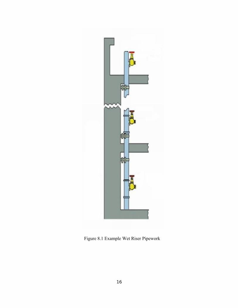
Figure 8.1 Example Wet Riser Pipework
16
9.0 DESIGN REQUIREMENTS
9.1 Wet Riser Landing Valve
Landing valve are provided on each floor should comply with M.S. 1210 Part 1. They
are usually located within fire fighting access lobbies, protected staircases or other protected
lobbies, and installed at not more than 0.75 metres from the floor. To protect the landing
valves, boxes can be provided and these should comply with M.S. 1210 Part 4.
The pressure at the landing valve should be no less than 4 bars and not more than 7
bars. To achieve this, they are to types of landing valves i.e. pressure reducing type with or
without relief outlet. Those with relief outlets require a wet riser return pipe. Fire hose of the
canvas type of not less than 38mm dia. 30 metres in length, complete with 65mm diameter
quick coupling and jet and spray nozzle should be provided in a hose cradle beside each
landing valve.
Figure 9.1.1 Pressure Reducing Type
17
9.2 Breeching Inlet
With the fire brigade breeching inlets the firemen can pump water into the wet riser
storage tank to make up for water use. The breeching inlet should be a 4-way tipe complying
with M.S. 1210 : Part 3. Where the breeching inlet is enclose within a box, the enclosure
should comply with M.S. 1210 : Part 5 and labeled ‘Wet Riser Inlet’. A drain should be
provided at the bottom of the riser to drain the system after use. Breeching inlet should be
located no more than 18 metres fron the fire appliance access road and not more than 30
metres from the nearest external hydrant.
9.3 Wet Riser Pipe
The wet riser mains are usually located within smoke free lobby or protected areas and
suck that all space are be to be within a 45 metres coverage from a landing valve. Where
more than one riser is required for each floor, the distance apart between the risers should not
exceed 60 metres. The distance between the lowest and topmost landing valve in any upper
stage riser should not exceed 60 metres. The riser pipe diameter should be 150mm
galvanized to B.S. 1387 (Heavy Gauge) or Class C. where a relief pipe is required, this return
pipe shall be minimum 100mm diameter galvanized iron to B.S. 1387 (Medium Gauge) or
Class B, discharging back to wet riser tank wherever possible. An air release valve should be
installed at the to of the riser to relief air trapped in the system. All wet riser pipes should be
coated with primer and finished with red gloss paint. Alternatively the pipe can be colour
coded with red bands of 100mm with and the elbows and tees painted red. The riser pipe
should be electrically earthed to achieve equipotential with the building.
18
9.4 Wet Riser Pumps
The wet riser pumps draw water from wet riser storage tank and two sets of pumps, one
on duty and the other on standby, are provided. The pump capacity is usually sized to the
deliver a flow rate of 1500 l/min at a running pressure of not less than 4 bars but not more
than 7 bars, when any three landing valves are in use at the same time.
The standby wet riser pumpset should be supplied with power from the emergency
generator if this is available. Otherwise, the standby pumpset should be diesel engine driven.
Fuel supply should be other adequate for minimum 2 hour of continuous operation. Electrical
cabling to supply power to the wet riser pumps should be of MICC or fire rated type.
Batteries for the diesel engine should be maintenance-free type.
The wet riser pumpsets should be protected from fire and away from locations likely to
be flooded. Sump pumps shall be installed where the fire pump room is located in the
basement below external drainage levels. It should also be ventilated by natural or
mechanical means and provided with the necessary signage. A carbon dioxide type portable
extinguisher should be provided as well.
Figure 9.4.1 Wet Riser Pump
19
9.5 Wet Riser Tanks
The fire water storage tank should be sized for a minimum effective capacity of 45500
litres with automatic refill rate of 455 l/min. the intermediate break tank for upper stages of
the wet riser should be not less than 11375 litres with and automatic make-up flow of 1365
l/min.
Wet riser tanks may be pressed steel, fibre reinforced polyester(FRP) or concrete.
Pressed steel tanks where use should be hot dipped galvanized and coated internally with
bituminous paint for corrosion protection. The water tanks should be compartmented unless
they are of reinforced concrete. Ball float valves, overflow pipes, drain pipes and water level
indicators should be provided for each compartment. The external surface of the tank should
be painted red or were this not desirable, a red band of minimum 200mm should be painted
indicated that this is a fire tank.
The wet riser tanks may be located on the ground floor, first or second basement. The
wet riser tanks are usually separated from other water storage tank. However it may be
combained with hose reel tank, in which cases the tank capacity should be the sum total of
the water storage for both wet riser and where as for hose reel system. The hose reel tap of
level should be above the wet riser tap off level such that the water riser reserve and
maintained.
20
9.6 Pump Starter Panels Controls
Pump starter panel should be complete with indicator lights as shown in the.
Ventilation slots should be provided with insect screen to prevent entry of vermin. Power
supply cables to the panel should be of mineral insulated copper cable (MICC) or fire rated
type routed within areas with low fire risk. The pump starter panel should be placed within
the same room as the fire pumps it controls.
Wet riser pumps are automatically started upon actuation of the pressure switches but should
only be stopped manually. Usually three pressure switches are provided with the following
suggested pressure settings:
• Starting the duty pumpset seet at 80% of the system pressure;
• Starting the standby pumpset set at 60% of the system pressure; and
• Starting and stopping the jockey pumpset set at 90% and 110% of the system pressure
respectively.
The pressure switches are normally installed in the test and drain line on the pump discharge
side. The pressure settings should be clearly labeled on tags attached to each pressure switch.
21
Figure 7.6 Automatic Starter Pump Panel Control
10.0 TEST REQUIREMENTS
10.1 Static Pressure Test
The system should first be flushed to clear all debris from the inside of the riser. The riser is
then hydraulically tested to a pressure of 14 bars or 150% the working pressure,
whichever is the higher for 2 hours, measured at the lowest landing valve connections.
10.2 Flow Test
A three way landing valve should be provided on the roof or topmost floor for testing
purposes. Means should be provided to measure the water flowrate.
11.0 MAINTENANCE REQUIREMENTS
11.1 Inspection and testing
A flow should be carried out to ensure that the pumps are in proper working condition.
The pipework should be checked for leakage and the breeching inlets, landing valves and
hoses, drain valves and cabinets should be inspected as recommended in the checklist
attached.
22
12.0 DESIGN CHECKLIST
(a) Wet riser is required for building where the topmost floor is more than 30.5 metres above fire
appliance access.
(b) A minimum flow rate of 500 litres/minute at running pressure of 4 to 7 bars is maintained at
each landing valve when three numbers of the furthest landing valves are fully opened.
(c) Water source :
• Pump suction tank
• Fire water main.
• Other : .
(d) Multi-stage system shall be installed for highest outlet more than 70.15 metres above pump
level.
(e) Each stage of riser does not exceed 60 metres.
(f) Landing valves shall be pressure regulating/reducing type.
23
(g) Total number of landing vavle per stage :
Stage 1 : nos.
Stage 2 : nos.
(h) Three way 63.5mm outlets are provided at location above the roof line.
(i) Riser spacing : metres.
(j) Rising main location :
• In stairway enclosure.
• Within fire fighting lobby.
• Other : .
(k) Number of fire hose provided : nos.
(l) Hose size : _____ mm ; length : ____ m.
(m) Break tank capacity : 11,375 litres.
(n) Water tank capacity : 45,500 litres.
(o) Minimum nominal diameter of riser shall be 150mm.
(p) Pipe material : .
(q) Lowest point of landing valve at about 750mm above floor level.
(r) To provide fire brigade breeching inlet.
(s) Wet riser pump :
Rated flow rate : ___ litres/min at metre head.
Rated power : kW.
(t) Pipe norminal size : Suction : mm ; Delivery : mm
24
(u) For diesel engine :
Fuel capacity sufficient to run engine at full load for hours.
Reserve supply of fuel for hours of engine full load running.
13.0 VISUAL INSPECTION CHECKLIST
13.1 Visual Inspection of Water Supplies
• Capacity of water available
• Compartmentation of water tanks.
• Priming tank (if any).
• Monitoring of water tank level.
• Vortex inhibitors for water tanks.
• Breeching inlet.
13.2 Visual Inspection of Landing Valves and Accessories
• Location of landing valve.
• Storage of canvas hose and accessories.
• Physical condition of canvas hose, accessories and landing valve.
• Caps for outlet of landing valves.
25
13.3 Visual Inspection of Pipework
• Type of pipes used.
• Protection of underground pipework.
• Painting pipework.
• Pipe supports.
• Pipe sleeves.
• Fire seal.
13.4 Visual Inspection of pumps
• Protection of rotating parts of pump sets.
• Mounting of pump sets.
14.0 TESTING AND COMMISIONING CHECKLIST
14.1 Testing and Commisioning of Water Supplies
26
• Pump operating current and voltage.
• Pump operating pressure and flow rate.
• Pump operating RPM.
• Pump not overheating.
• Vibration and noise level.
• Testing of electrical wiring system.
• Alternative power supply for electric pumps.
• Batteries for diesel pumps.
• Fuel for pumps.
• Automatic operation of pumps.
14.2 Testing and Commissioning of Pipework
• Hydrostatic testing of pipework.
• Flushing pipework.
14.3 Testing and Commissioning of Landing Valves
• Pressure at landing valve outlet.
27
• Flow rate water.
28
15.0 CONCLUSION
Dry risers are a form of internal hydrant for the firemen to use and are only required
for buildings where the topmost floor is higher than 18.3 metres and less than 30.5 metres
above the fire appliance access level. Dry risers are normally dry and depend on the fire
engine to pump water into system. Dry riser system comprises a riser pipe with landing
valves at each floor and to which canvas hose with nozzles can be connected to direct the
water jet at the fire. Breeching inlets into which the firemen pumps water are provided at
ground and are connected to the bottom of the dry risers.
Wet risers are a form of internal hydrant for the firemen to use always charged
with water. Wet risers are only required for building where the topmost floor is higher
than 30.5 metres above the fire appliance access level. Wet riser system comprises duty
fire pump wit standby pump discharging into a 150mm diameter riser pipe with landing
valves at each floor and to which canvas hose with nozzles can be connected to direct the
water jet at the fire. A jockey pump is usually provided to maintain system pressure. For
high rise buildings, each stage of the wet riser should not exceed 70.15 metres.