133
NUREG-2224 Office of Nuclear Material Safety and Safeguards Dry Storage and Transportation of High Burnup Spent Nuclear Fuel Final Report

NUREG-2224
Office of Nuclear Material Safety and Safeguards
Dry Storage and Transportation of High Burnup Spent Nuclear Fuel
Final Report
AVAILABILITY OF REFERENCE MATERIALSIN NRC PUBLICATIONS
NRC Reference Material
As of November 1999, you may electronically access NUREG-series publications and other NRC records at the NRC’s Library at www.nrc.gov/reading-rm.html. Publicly released records include, to name a few, NUREG-series publications; Federal Register notices; applicant, licensee, and vendor documents and correspondence; NRC correspondence and internal memoranda; bulletins and information notices; inspection and investigative reports; licensee event reports; and Commission papers and their attachments.
NRC publications in the NUREG series, NRC regulations, and Title 10, “Energy,” in the Code of Federal Regulations may also be purchased from one of these two sources:
1. The Superintendent of DocumentsU.S. Government Publishing Office Washington, DC 20402-0001Internet: www.bookstore.gpo.govTelephone: (202) 512-1800Fax: (202) 512-2104
2. The National Technical Information Service 5301 Shawnee RoadAlexandria, VA 22312-0002Internet: www.ntis.gov1-800-553-6847 or, locally, (703) 605-6000
A single copy of each NRC draft report for comment isavailable free, to the extent of supply, upon writtenrequest as follows:
Address: U.S. Nuclear Regulatory Commission Office of Administration Multimedia, Graphics, and Storage & Distribution Branch Washington, DC 20555-0001 E-mail: [email protected] Facsimile: (301) 415-2289
Some publications in the NUREG series that are posted at the NRC’s Web site address www.nrc.gov/reading-rm/doc-collections/nuregs are updated periodically and may differ from the last printed version. Although references to material found on a Web site bear the date the material was accessed, the material available on the date cited may subsequently be removed from the site.
Non-NRC Reference Material
Documents available from public and special technical libraries include all open literature items, such as books, journal articles, transactions, Federal Register notices, Federal and State legislation, and congressional reports. Such documents as theses, dissertations, foreign reports and translations, and non-NRC conference proceedings may be purchased from their sponsoring organization.
Copies of industry codes and standards used in asubstantive manner in the NRC regulatory process are maintained at—
The NRC Technical Library Two White Flint North 11545 Rockville Pike Rockville, MD 20852-2738
These standards are available in the library for reference use by the public. Codes and standards are usually copyrighted and may be purchased from the originating organization or, if they are American National Standards, from—
American National Standards Institute 11 West 42nd StreetNew York, NY 10036-8002Internet: www.ansi.org(212) 642-4900
Legally binding regulatory requirements are stated only in laws; NRC regulations; licenses, including technical specifications; or orders, not in NUREG-series publications. The views expressed in contractor prepared publications in this series are not necessarily those of the NRC.
The NUREG series comprises (1) technical and administrative reports and books prepared by the staff (NUREG–XXXX) or agency contractors (NUREG/CR–XXXX), (2) proceedings of conferences (NUREG/CP–XXXX),(3) reports resulting from international agreements(NUREG/IA–XXXX),(4) brochures (NUREG/BR–XXXX), and(5) compilations of legal decisions and orders of the Commission and the Atomic and Safety Licensing Boards and of Directors’ decisions under Section 2.206 of the NRC’s regulations (NUREG–0750).
DISCLAIMER: This report was prepared as an account of work sponsored by an agency of the U.S. Government. Neither the U.S. Government nor any agency thereof, nor any employee, makes any warranty, expressed or implied, or assumes any legal liability or responsibility for any third party’s use, or the results of such use, of any information, apparatus, product, or process disclosed in this publication, or represents that its use by such third party would not infringe privately owned rights.

Dry Storage and Transportation of High Burnup Spent Nuclear Fuel Final Report
Manuscript Completed: November 2020 Date Published: November 2020
Office of Nuclear Material Safety and Safeguards
NUREG-2224


iii
ABSTRACT
The purpose of this report is to expand the technical basis in support of the U.S. Nuclear Regulatory Commission’s (NRC’s) guidance on adequate fuel conditions as it pertains to hydride reorientation in high burnup (HBU) spent nuclear fuel (SNF) cladding. This guidance defines adequate fuel conditions, including peak cladding temperatures during short-term loading operations to prevent or mitigate degradation of the cladding. Time-dependent changes on the cladding properties of HBU SNF are primarily driven by the fuel’s temperature, rod internal pressure (and corresponding pressure-induced cladding hoop stresses), and the environment during dry storage or transport operations. Historically, safety review guidance has addressed the potential for these changes to compromise the analyzed fuel configuration in dry storage systems and transportation packages.
Hydride reorientation is a process in which the orientation of hydrides precipitated in HBU SNF cladding during reactor operation changes from the circumferential-axial to the radial-axial direction. Research results over the last decade have shown that hydride reorientation can still occur at temperatures and stresses lower than those assumed in the current staff review guidance. Therefore, the NRC has since sponsored additional research to better understand whether hydride reorientation could affect the mechanical behavior of HBU SNF cladding and compromise the fuel configuration analyzed in dry storage systems and transportation packages.
This report provides an engineering assessment of the results of research on the mechanical performance of HBU SNF following hydride reorientation. Based on the conclusions of that assessment, the report then presents example approaches for licensing and certification of HBU SNF for dry storage (under Title 10 of the Code of Federal Regulations (10 CFR) Part 72, “Licensing Requirements for the Independent Storage of Spent Nuclear Fuel, High-Level Radioactive Waste, and Reactor-Related Greater Than Class C Waste”) and transportation (under 10 CFR Part 71, “Packaging and Transportation of Radioactive Material”).
The NRC expects these example licensing and certification approaches, when followed by applicants, to minimize or eliminate the need for requests for additional information during the staff’s safety review of applications for dry storage and transportation of HBU SNF. Further, the NRC expects that future revisions of the standard review plans for dry storage systems and transportation packages will reference the licensing and certification approaches delineated in this NUREG.
The information in this report is not intended for use in applications for wet storage facilities or monitored retrievable storage installations licensed under 10 CFR Part 72.
Nothing contained in this report is to be construed as having the force or effect of regulations. Comments regarding errors or omissions, as well as suggestions for improvement of this NUREG, should be sent to the Director, Division of Spent Fuel Management, U.S. Nuclear Regulatory Commission, Washington, DC, 20555-0001.
Congressional Review Act Statement
This NUREG is a rule as defined in the Congressional Review Act (5 U.S.C. 801-808). However, the Office of Management and Budget has not found it to be a major rule as defined in the Congressional Review Act.

iv
Paperwork Reduction Act
This NUREG provides guidance for implementing the mandatory information collections in 10 CFR Parts 71 and 72 that are subject to the Paperwork Reduction Act of 1995 (44 U.S.C. 3501 et seq.). The Office of Management and Budget (OMB) approved these information collections under control numbers 3150-0008 and 3150-0132. Send commentsregarding this information collection to the Information Services Branch, U.S. Nuclear Regulatory Commission, Washington, DC 20555-0001, or by e-mail to [email protected], and to the Desk Officer, Office of Information and Regulatory Affairs, NEOB-10202 (3150-0008, 3150-0132), Office of Management and Budget, Washington, DC 20503.
Public Protection Notification
The NRC may not conduct or sponsor, and a person is not required to respond to, a collection of information unless the document requesting or requiring the collection displays a currently valid OMB control number.

v
CONTENTS
ABSTRACT ................................................................................................................... iii
CONTENTS .................................................................................................................... v
LIST OF FIGURES......................................................................................................... ix
LIST OF TABLES .......................................................................................................... xi
ACKNOWLEDGMENTS .............................................................................................. xiii
ABBREVIATIONS AND ACRONYMS .......................................................................... xv
1 INTRODUCTION ............................................................................................... 1-1
1.1 Background .......................................................................................................1-1
1.2 Fuel Cladding Performance and Staff’s Review Guidance ................................1-2
1.3 Cladding Creep .................................................................................................1-4
1.4 Effects of Hydrogen on Cladding Mechanical Performance ...............................1-5
1.5 Hydride Reorientation .......................................................................................1-7
1.5.1 Hydride Dissolution and Precipitation ....................................................1-8
1.5.2 Fuel Cladding Fabrication Process ...................................................... 1-10
1.5.3 End-of-Life Rod Internal Pressures and Cladding Hoop Stresses .............................................................................................. 1-11
1.5.4 Ring Compression Testing .................................................................. 1-16
1.5.5 Staff’s Assessment of Ring Compression Testing Results ................... 1-22
2 ASSESSMENT OF STATIC BENDING AND FATIGUE STRENGTH RESULTS ON HIGH BURNUP SPENT NUCLEAR FUEL................................ 2-1
2.1 Introduction .......................................................................................................2-1
2.2 Cyclic Integrated Reversible Fatigue Tester ......................................................2-1
2.3 Application of the Static Test Results ................................................................2-6
2.3.1 Spent Fuel Rod Behavior in Bending .....................................................2-7
2.3.2 Composite Behavior of a Spent Fuel Rod ..............................................2-7
2.3.3 Calculation of Cladding Strain from CIRFT Static Bending Data .......... 2-10
2.3.4 Calculation of Cladding Strain Using Factored Cladding-Only Properties ............................................................................................ 2-13
2.3.5 Applicability to Dry Storage and Transportation ................................... 2-17
2.3.5.1 Use of Static Test Results to Evaluate Safety Margins in a Hypothetical Accident Condition Side-Drop Event .......... 2-20
2.3.5.2 Dynamic Response of a Fuel Rod ........................................ 2-22

vi
2.3.5.3 Seismic Response of a Fuel Rod .......................................... 2-22
2.3.5.4 Thermal Cycling during Loading Operations ......................... 2-23
2.4 Application of Fatigue Test Results ................................................................. 2-23
2.4.1 Lower-Bound Fatigue S-N Curves ....................................................... 2-23
2.4.2 Fatigue Cumulative Damage Model ..................................................... 2-27
2.4.3 Applicability to Storage and Transportation ......................................... 2-27
2.4.3.1 Seismic Events ..................................................................... 2-28
2.4.3.2 Thermal Cycling during Loading Operations ......................... 2-28
3 DRY STORAGE OF HIGH BURNUP SPENT NUCLEAR FUEL ...................... 3-1
3.1 Introduction .......................................................................................................3-1
3.2 Uncanned Fuel (Intact and Undamaged Fuel) ...................................................3-4
3.2.1 Leaktight Confinement ...........................................................................3-7
3.2.2 Nonleaktight Confinement .....................................................................3-8
3.2.3 Dry Storage up to 20 Years ................................................................. 3-11
3.2.4 Dry Storage Beyond 20 Years ............................................................. 3-12
3.2.4.1 Supplemental Results from Confirmatory Demonstration ...................................................................... 3-12
3.2.4.1.1 Initial Licensing or Certification ........................ 3-12
3.2.4.1.2 Renewal Applications....................................... 3-13
3.2.4.2 Supplemental Safety Analyses ............................................. 3-13
3.2.4.2.1 Materials and Structural ................................... 3-14
3.2.4.2.2 Confinement .................................................... 3-14
3.2.4.2.3 Thermal ........................................................... 3-14
3.2.4.2.4 Criticality .......................................................... 3-15
3.2.4.2.5 Shielding .......................................................... 3-17
3.3 Canned Fuel (Damaged Fuel) ......................................................................... 3-20
4 TRANSPORTATION OF HIGH BURNUP SPENT NUCLEAR FUEL ............... 4-1
4.1 Introduction .......................................................................................................4-1
4.2 Uncanned Fuel (Intact and Undamaged Fuel) ...................................................4-4
4.2.1 Leaktight Containment ...........................................................................4-7
4.2.2 Nonleaktight Containment .....................................................................4-7
4.2.3 Direct Shipment from the Spent Fuel Pool and Shipment of Previously Dry-Stored Fuel (Up to 20 Years Since Fuel Was Initially Loaded) ................................................................................... 4-11
4.2.4 Shipment of Previously Dry-Stored Fuel (Beyond 20 Years Since Fuel Was Initially Loaded) ......................................................... 4-12

vii
4.2.4.1 Supplemental Data from Confirmatory Demonstration .......... 4-12
4.2.4.2 Supplemental Safety Analyses ............................................. 4-12
4.2.4.2.1 Materials and Structural ................................... 4-13
4.2.4.2.2 Containment .................................................... 4-13
4.2.4.2.3 Thermal ........................................................... 4-14
4.2.4.2.4 Criticality .......................................................... 4-15
4.2.4.2.5 Shielding .......................................................... 4-18
4.3 Canned Fuel ................................................................................................... 4-20
5 CONCLUSIONS ................................................................................................ 5-1
6 REFERENCES .................................................................................................. 6-1


ix
LIST OF FIGURES
Figure 1-1 Average hydride content [H] and distribution in HBU SNF cladding.................. 1-6 Figure 1-2 Dissolution (Cd) and precipitation (Cp) concentration curves............................. 1-9 Figure 1-3 Publicly available data collected by EPRI for PWR EOL rod internal
pressures at 25 degrees C (77 degrees F) ..................................................... 1-12 Figure 1-4 Fuel cladding tube with stress element displaying hoop stress (σθ),
longitudinal stress (σz), internal pressure (Pi), cladding thickness (hm), external pressure (Po), circumferential coordinate (θ), and inner cladding diameter (Dmi) ................................................................................................ 1-14
Figure 1-5 RCT of a sectioned cladding ring specimen in ANL’s Instron 8511 test setup ....................................................................................................... 1-17
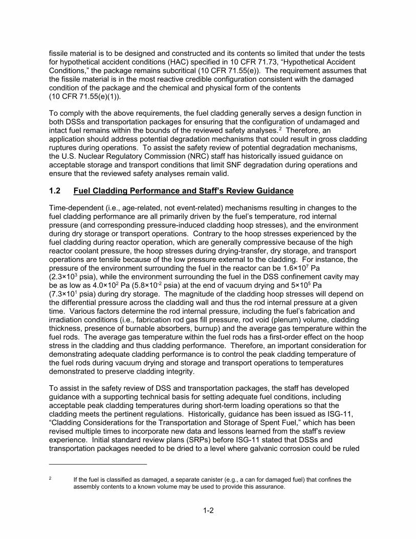
Figure 1-6 Effective ductility versus RCT for two PWR cladding alloys following slow cooling from 400 degrees C (752 degrees F) at peak target hoop stresses of 110 MPa (1.6×10⁴ psia) and 140 MPa (2.0×10⁴ psia) ................................. 1-18
Figure 1-7 Ductility data, as measured by RCT, for as-irradiated Zircaloy-4 and Zircaloy-4 following cooling from 400 degrees C (752 degrees F) under decreasing internal pressure and hoop stress conditions ............................... 1-19
Figure 1-8 Ductility data, as measured by RCT, for as-irradiated ZIRLO and ZIRLO following cooling from 400 degrees C (752 degrees F) under decreasing internal pressure and hoop stress conditions ................................................. 1-20
Figure 1-9 Ductility data, as measured by RCT, for as-irradiated M5 and M5 following cooling from 400 degrees C (752 degrees F) under decreasing internal pressure and hoop stress conditions .............................................................. 1-21
Figure 1-10 Geometric models for spent fuel assemblies in transportation packages ....... 1-23 Figure 2-1 Horizontal layout of ORNL U-frame setup (top), rod specimen and three
LVDTs for curvature measurement (middle), and front view of CIRFT installed in ORNL hot cell (bottom) ................................................................... 2-3
Figure 2-2 Schematic diagram of end- and side-drop accident scenarios.......................... 2-7 Figure 2-3 Typical composite construction of a bridge....................................................... 2-9 Figure 2-4 Influence of cg position on composite beam stiffness .................................... 2-10 Figure 2-5 Images of cladding-pellet structure in HBU SNF rod ...................................... 2-11 Figure 2-6 Approximate extreme fiber tensile stresses between pellet-pellet crack ......... 2-12 Figure 2-7 Comparison of CIRFT static bending results with calculated PNNL
moment curvature (flexural rigidity) derived from cladding-only stress-strain curve .......................................................................................... 2-13
Figure 2-8 Characteristic points on moment-curvature curve .......................................... 2-14 Figure 2-9 High-magnification micrograph showing radial hydrides of an HBR HBU
SNF hydride-reoriented specimen tested under Phase II ............................... 2-18 Figure 2-10 Representative conditions used for radial hydride treatment for preparation
of HBR HBU SNF hydride-reoriented specimens tested under Phase II ......... 2-19

x
Figure 2-11 Plots of half of the cladding strain range (∆ε/2) and the maximum strain (/ε/max) as a function of number of cycles to failure ................................ 2-25
Figure 2-12 CIRFT dynamic (fatigue) test results for as-irradiated and hydride-reoriented HBR Zircaloy-4 HBU fuel rods .......................................... 2-26
Figure 3-1 Example licensing and certification approaches for dry storage of high burnup spent nuclear fuel ................................................................................. 3-3
Figure 3-2 First approach for evaluation of design-bases drop accidents during dry storage ....................................................................................................... 3-5
Figure 3-3 Second approach for evaluation of design-bases drop accidents during dry storage ....................................................................................................... 3-7
Figure 4-1 Example approaches for approval of transportation packages with high burnup spent nuclear fuel ................................................................................. 4-3
Figure 4-2 First approach for evaluation of drop accidents during transport ...................... 4-5 Figure 4-3 Second approach for evaluation of drop accidents during transport ................. 4-6 Figure 4-4 Evaluation of vibration normally incident to transport ....................................... 4-7

xi
LIST OF TABLES
Table 1-1 EOL rod internal pressures (MPa) at a peak temperature of 400 degrees C (752 degrees F) ............................................................................................. 1-13
Table 1-2 Maximum cladding hoop stresses (MPa) at a peak temperature of 400 degrees C (752 degrees F) .................................................................... 1-15
Table 1-3 EOL rod internal pressures at room temperature (25 degrees C (77 degrees F)) and atmospheric conditions (1.0×10⁻¹ MPa (1.5×101 psia)) ... 1-15
Table 2-1 Specifications of rod specimens used in NRC-sponsored HBU SNF test program ........................................................................................................... 2-4
Table 2-2 Comparison of average flexural rigidity results between CIRFT static testing and PNNL cladding-only data ............................................................. 2-15
Table 2-3 Characteristic points and quantities based on moment-curvature curves …... 2-15
Table 2-4 PWR 15 × 15 SNF assembly parameters ....................................................... 2-21
Table 2-5 Summary of CIRFT dynamic test results for as-irradiated and hydride-reoriented HBR HBU SNF ................................................................. 2-24
Table 2-6 Coordinates for lower-bound enveloping S-N curve for the HBR HBU SNF rods ....................................................................................................... 2-25
Table 3-1 Fractions of radioactive materials available for release from HBU SNF under conditions of dry storage ........................................................................ 3-9
Table 4-1 Fractions of radioactive materials available for release from HBU SNF under conditions of transport ............................................................................ 4-9


xiii
ACKNOWLEDGMENTS
The working group is very grateful to M. Billone (Argonne National Laboratory) for providing valuable input to the writing of the report, to Olivier Lareynie (French Nuclear Safety Authority) for assisting in the preparation of responses to comments on this report, and to J. Wang (Oak Ridge National Laboratory) for providing valuable insights, observations, and recommendations.


xv
ABBREVIATIONS AND ACRONYMS
ADAMS Agencywide Documents Access and Management System ANL Argonne National Laboratory ANS American Nuclear Society ANSI American National Standards Institute
b width BWR boiling-water reactor
Cd concentration at dissolution Cp concentration at precipitation CFR Code of Federal Regulations cg center of gravity CoC certificate of compliance CIRFT cyclic integrated reversible-bending fatigue tester CRUD Chalk River unknown deposit CWSRA cold-worked, stress-relieved annealed
δp/Dmo offset strain ΔTdp temperature hysteresis (dissolution-precipitation) Dmi inner (metal) cladding diameter Dmo outer (metal) cladding diameter DLF dynamic load factor DTT ductility transition temperature DOE U.S. Department of Energy DSS dry storage system
ε average tensile strain ε-N strain per number of cycles E elastic modulus Ec elastic modulus of the cladding EI flexural rigidity Ep elastic modulus of the fuel pellet EOL end-of-life EPRI Electric Power Research Institute
GBC general burnup credit GTCC greater than Class C
h height hm cladding (metal) thickness HAC hypothetical accident conditions (transportation) HBR H.B. Robinson Steam Electric Plant HBU high burnup HRT hydride reorientation treatment
I moment of inertia Ic moment of inertia of the cladding Ip moment of inertia of the fuel pellet

xvi
IAEA International Atomic Energy Agency IFBA integral fuel burnable absorber ISFSI independent spent fuel storage installation ISG interim staff guidance
κ curvature κ-N curvature per number of cycles keff k-effective
l rod length between spacers LBU low burnup LVDT linear variable differential transformer
M bending moment
ni number of strain cycles at strain level εi Ni number of strain cycles to produce failure at εi NCT normal conditions of transport NRC U.S. Nuclear Regulatory Commission
OMB Office of Management and Budget ORNL Oak Ridge National Laboratory
Pi rod internal pressure Po rod external pressure PNNL Pacific Northwest National Laboratory PWR pressurized-water reactor
r outer radius RCT ring compression testing RHCF radial hydride continuity factor RIP rod internal pressure RXA recrystallized annealed
σ average tensile stress σθ cladding hoop stress σz cladding longitudinal stress SAR safety analysis report SM safety margin SNF spent nuclear fuel SRP standard review plan SSC structure, system, and component
θ circumferential coordinate Td dissolution temperature Tp precipitation temperature
w uniform applied load
ymax distance to the neutral axis

xvii
Units of Measure
C Celsius F Fahrenheit ft foot g 9.806 m/s2 GPa gigapascal, 1x10⁹ pascals GWd/MTU gigawatt-days per metric ton of uranium h hour in. inch lb pound m meter μm micrometer, 1×10⁻⁶ meter mm millimeter, 0.001 meter MPa megapascal, 1×10⁶ pascals N newton N·m newton meter Pa pascal psia pounds per square inch (absolute) s second wppm parts per million by weight


xix
GLOSSARY
Accident condition of storage
The extreme level of an event or condition, which has a specified resistance, limit of response, and requirement for a given level of continuing capability, which exceeds off-normal events or conditions. Accident conditions include both design-basis accidents and conditions caused by natural and manmade phenomena.
Aging management program
See Title 10 of the Code of Federal Regulations (10 CFR) 72.3, “Definitions.”
Amendment of a license or certificate of compliance (CoC)
An application for amendment of a license or a CoC must be submitted whenever a holder of a specific license or CoC wants to change the license or CoC (including a change to the technical specifications that accompany the license or CoC conditions). The application must fully describe the desired change(s) and the reason(s) for such change(s), and follow, as far as applicable, the form prescribed for original applications. See 10 CFR 72.56, “Application for Amendment of License,” and 10 CFR 72.244, “Application for Amendment of a Certificate of Compliance.”
Assembly defect Any change in the physical as-built condition of the spent fuel assembly except for normal in-reactor changes such as elongation from irradiation growth or assembly bow. Examples of assembly defects include (1) missing rods, (2) broken or missing grids or grid straps (spacers), and (3) missing or broken grid springs.
Breached spent nuclear fuel rod
A spent nuclear fuel (SNF) rod with cladding defects that permit the release of gases or solid fuel particulates from the interior of the fuel rod. SNF rod breaches include pinhole leaks, hairline cracks, and gross ruptures.
Burnup The measure of thermal power produced in a specific amount of nuclear fuel through fission, usually expressed in gigawatt-day per metric ton uranium (GWd/MTU). For the purpose of assessing the allowable contents, the maximum burnup of the fuel is generally specified in terms of the average burnup of the entire fuel assembly (i.e., assembly average). For the purpose of assessing fuel cladding integrity in the materials and structural review, the rod with the highest burnup within the fuel assembly is generally specified in terms of peak rod average burnup.
Can for damaged fuel A metal enclosure that is sized to confine damaged SNF contents. A can for damaged fuel must satisfy fuel-specific and dry storage system/package-related functions for undamaged SNF, as required by the applicable regulations.

xx
Canister (in a dry storage system)
A metal cylinder that is sealed at both ends and may be used to perform the function of confinement. Typically, a separate overpack performs the radiological shielding and physical protection function.
Certificate of compliance (CoC) (for a dry storage system)
The certificate issued by the U.S. Nuclear Regulatory Commission (NRC) that approves the design of a spent fuel storage cask in accordance with the provisions of 10 CFR Part 72, “Licensing Requirements for the Independent Storage of Spent Nuclear Fuel, High-Level Radioactive Waste, and Reactor-Related Greater Than Class C Waste,” Subpart L, “Approval of Spent Fuel Storage Casks.” See 10 CFR 72.3.
Certificate of compliance (CoC) (for a transportation package)
The certificate issued by the NRC that approves the design of a package for the transportation of radioactive material in accordance with the provisions of 10 CFR Part 71, “Packaging and Transportation of Radioactive Material,” Subpart D, “Application for Package Approval.” See 10 CFR 71.4, “Definitions.”
Certificate holder (for a dry storage system)
A person who has been issued a CoC by the NRC for a spent fuel storage cask design under 10 CFR Part 72. See 10 CFR 72.3.
Certificate holder (for a transportation package)
A person who has been issued a CoC or other package approval by the NRC under 10 CFR Part 71. See 10 CFR 71.4.
Certificate of compliance user (CoC user)
The general licensee that has loaded a dry storage system, or purchased a dry storage system (DSS) and plans to load it, in accordance with a CoC issued under 10 CFR Part 72.
Confinement (in a dry storage system for spent nuclear fuel)
The ability to limit or prevent the release of radioactive substances into the environment.
Confinement systems Those systems, including ventilation, that act as barriers between areas containing radioactive substances and the environment. See 10 CFR 72.3.
Containment system The assembly of components of the packaging intended to retain the radioactive material during transport. See 10 CFR 71.4.
Controlled area See 10 CFR 72.3 and 10 CFR 20.1003, “Definitions.” The definition in 10 CFR 20.1003 is broader in scope and allows for, or includes, establishment of access controls to areas within the site for any reason (for radiation protection).
Criticality The condition wherein a system or medium is capable of sustaining a nuclear chain reaction.
Damaged spent nuclear fuel
Any spent fuel rod or spent fuel assembly that cannot meet the pertinent fuel-specific or system-related regulations for the

xxi
transportation package (10 CFR Part 71) or dry storage system (10 CFR Part 72).
Degradation Any change in the properties of a material that adversely affects the performance of that material; adverse alteration. See NUREG-2215, “Standard Review Plan for Spent Fuel Dry Storage Systems and Facilities – Final Report,” issued February 2020 (NRC, 2020).
Design bases (storage) Information that identifies the specific function(s) to be performed by structures, systems, and components (SSCs) (both important to safety and not important to safety) of a facility or of a spent fuel storage cask and the specific values or ranges of values chosen for controlling parameters as reference bounds for design. These values may be (1) restraints, derived from generally accepted “state-of-the-art”practices for achieving functional goals, or (2) requirements, derivedfrom analysis (based on calculation, experiments, or both) of the effectsof a postulated event in which SSCs must meet their functional goals.See 10 CFR 72.3.
Dry storage The storage of SNF in a DSS, which typically involves drying the DSS cavity and backfilling with an inert gas.
Dry storage system (DSS)
A system that typically uses a cask or canister in an overpack as a component in which to store SNF in a dry environment. A DSS provides confinement, radiological shielding, subcriticality control, structural support, and passive cooling of its SNF during normal, off-normal, and accident conditions. A DSS design may be approved under a CoC, as listed in 10 CFR 72.214, “List of Approved Spent Fuel Storage Casks,” or licensed under a specific license for an independent spent fuel storage installation (ISFSI).
g-load The acceleration experienced by an object with mass under its own self weight.
General license (storage)
Authorizes the storage of spent fuel in an ISFSI at a power reactor site by persons (see definition of person in 10 CFR 72.3) authorized to possess or operate nuclear power reactors under 10 CFR Part 50, “Domestic Licensing of Production and Utilization Facilities,” or 10 CFR Part 52, “Licenses, Certifications, and Approvals for Nuclear Power Plants.” The general license is limited to (1) that spent fuel which the general licensee is authorized to possess at the site under the specific 10 CFR Part 50 or 10 CFR Part 52 license for the site, and (2) storage of spent fuel in casks approved under the provisions of10 CFR Part 72, Subpart L, and listed in 10 CFR 72.214. See10 CFR 72.210, “General License Issued,” and10 CFR 72.212(a)(1)–(2).
Gross breach A breach in the spent fuel cladding that is larger than either a pinhole leak or a hairline crack and allows the release of particulate matter from the spent fuel rod.

xxii
Hairline crack A minor SNF cladding defect that will not permit significant release of particulate matter from the spent fuel rod and therefore presents a minimal as-low-as-is-reasonably-achievable concern during fuel handling operations.
High burnup (HBU) spent nuclear fuel
SNF with assembly average burnup (see “Burnup”) generally exceeding 45 GWd/MTU.
Hoop stress The tensile stress in cladding wall in the circumferential orientation of the fuel rod.
Important to safety (storage)
See SSCs important to safety.
Independent spent fuel storage installation (ISFSI)
A complex designed and constructed for the interim storage of spent nuclear fuel, solid reactor-related greater-than-Class-C (GTCC) waste, and other radioactive materials associated with spent fuel and reactor-related GTCC waste storage. See 10 CFR 72.3.
Intact spent nuclear fuel
A subset of undamaged SNF. Any fuel rod or fuel assembly that can meet the pertinent fuel-specific or system-related regulations for the transportation package (10 CFR Part 71) or dry storage system (10 CFR Part 72). Intact SNF rods may not contain pinholes, hairline cracks, or gross ruptures. Intact SNF assemblies may have assembly defects if able to meet the pertinent fuel-specific or system-related regulations.
Intended function (storage)
A design-basis function defined as either (1) important to safety or (2) the failure of which could impact a safety function.
Interim staff guidance (ISG)
Supplemental information that clarifies important aspects of regulatory requirements. An ISG provides review guidance to NRC staff in a timely manner until standard review plans are revised accordingly.
keff (“k-effective”) Effective neutron multiplication factor including all biases and uncertainties at a 95-percent confidence level for indicating the level of subcriticality relative to the critical state. At the critical state, keff = 1.0. This has also been used to represent effective thermal conductivity.
Leaktight The degree of package containment that, in a practical sense, precludes any significant release of radioactive materials. This degree of containment is achieved by demonstration of a leakage rate less than or equal to 1×10⁻⁷ ref.·cm3/s of air at an upstream pressure of 1 atmosphere (atm) absolute (abs) and a downstream pressure of 0.01 atm abs or less.
Low burnup (LBU) spent nuclear fuel
Spent nuclear fuel with an assembly average burnup (see “Burnup”) generally less than 45 GWd/MTU.
M5® (M5) AREVA-trademarked fuel cladding alloy, which contains zirconium and niobium.

xxiii
Nonfuel hardware Hardware that is not an integral part of a fuel assembly. This is the term used to identify what the regulation refers to as “other radioactive materials associated with fuel assemblies” (see SNF definition in 10 CFR 72.3). While not integral to the assembly, it includes those items that are designed to operate and are positioned or operated within the envelope of the fuel assembly during reactor operation and are stored within the assembly envelope in the storage container. Typical examples of nonfuel hardware include burnable poison rod assemblies, control element assemblies, thimble plug assemblies, and boiling-water reactor (BWR) fuel channels. Examples of items that do not meet this definition include boron sources, BWR in-core instruments, and BWR control blades.
Nonmechanistic event (dry storage)
An event, such as cask tipover, which should be evaluated for acceptable system capability, although a cause for such an event is not identified in the analyses of off-normal and accident events and conditions.
Normal events or conditions of storage
Conditions that are intended operations, planned events, and environmental conditions that are known or reasonably expected to occur with high frequency during storage operations. “Normal” refers to the maximum level of an event or condition that is expected to routinely occur (similar to Design Event I as defined in American National Standards Institute/American Nuclear Society (ANSI/ANS) 57.9, “Design Criteria for an Independent Spent Fuel Storage Installation (Dry Storage Type)”). The DSS or ISFSI SSCs are expected to remain fully functional and to experience no temporary or permanent degradation of that functionality from normal operations, events, and conditions. Specific normal conditions to be addressed are evaluated for the DSS or ISFSI and are documented in a safety analysis report for that system or facility.
Normal means (dry storage)
The ability to move a fuel assembly with a crane and grapple used to move undamaged assemblies at the point of cask loading. The addition of special tooling or modifications to the assembly to make the assembly suitable for lifting by crane and grapple does not preclude the assembly from being considered movable by normal means.
Off-normal events or conditions of storage
An event or condition that, although not occurring regularly, can be expected to occur with moderate frequency and for which there is a corresponding maximum specified resistance, limit of response, or requirement for a given level of continuing capability. “Off-normal” events and conditions are similar to a “Design Event II” in ANSI/ANS 57.9. A DSS or ISFSI SSC is expected to experience off-normal events and conditions without permanent degradation of capability to perform its full function (although operations may be suspended or curtailed during off-normal conditions) over the full storage term (the license period for a specific license facility or the storage period equivalent to the certificate term for a DSS). Off-normal events or conditions are referred to as anticipated occurrences in

xxiv
10 CFR 72.104, “Criteria for Radioactive Materials in Effluents and Direct Radiation from an ISFSI or MRS.”
Package (transportation)
The packaging together with its radioactive contents as presented for transport. See 10 CFR 71.4.
Packaging (transportation)
The assembly of components necessary to ensure compliance with the packaging requirements of 10 CFR Part 71. It may consist of one or more receptacles, absorbent materials, spacing structures, thermal insulation, radiation shielding, and devices for cooling or absorbing mechanical shocks. The vehicle, tie-down system, and auxiliary equipment may be designated as part of the packaging. See 10 CFR 71.4.
Pinhole leak A minor cladding defect that will not permit significant release of particulate matter from the spent fuel rod and therefore will present a minimal as-low-as-is-reasonably-achievable concern during fuel handling operations.
Ready retrieval (dry storage)
The ability to safely remove the spent fuel from storage for further processing or disposal.
Recovery (dry storage)
The capability of returning the stored radioactive materials from an accident to a safe condition without endangering public health and safety or causing significant or unnecessary exposure to workers. Any potential release of radioactive materials during recovery operations must not result in doses or radiation exposures that exceed the limits in 10 CFR Part 20, “Standards for Protection against Radiation.” Doses during recovery operations are included in the dose estimates for accidents, the total of which must not exceed the limits in 10 CFR 72.106, “Controlled Area of an ISFSI or MRS.”
Renewal of a license or CoC (dry storage)
A certificate holder may apply for renewal of the design of a spent fuel storage cask for a term not to exceed 40 years. If the certificate holder does not apply for a cask design renewal, any licensee using a spent fuel storage cask, a representative of the licensee, or another certificate holder may apply for a renewal of that cask design for a term not to exceed 40 years. See 10 CFR 72.240, “Conditions for Spent Fuel Storage Cask Renewal.” The Commission may renew specific licenses at the expiration of the license term upon application by the licensee for a period not to exceed 40 years. See 10 CFR 72.42, “Duration of License; Renewal.” The current regulatory framework for storage of spent fuel allows for multiple license or CoC renewals, subject to an aging management analysis and planning.
Safety analysis report (SAR) (dry storage)
The report submitted to the NRC staff by an applicant for a CoC for a DSS design, or for a specific license for an ISFSI, to present information on the design and operations of the system or facility. This document provides the justification and analyses to demonstrate that the design meets regulatory requirements and acceptance criteria (10 CFR 72.24, “Contents of Application: Technical Information,” and

xxv
10 CFR 72.230(a)). The SAR is submitted for approval of the ISFSI or DSS design. The final SAR is as defined in 10 CFR 72.48(a)(5).
Safety function (dry storage)
The functions that DSS and DSF SSCs important to safety (see 10 CFR 72.3) are designed to maintain or perform, including the following:
• protection against environmental conditions • content temperature control • radiation shielding • confinement • subcriticality control • retrievability
Specific license (dry storage)
A license issued by the NRC to authorize the receipt, handling, storage, and transfer of spent fuel, high-level radioactive waste, or reactor-related GTCC waste at an ISFSI or MRS facility. The NRC issues the license to a named person (see definition of “person” in 10 CFR 72.3) after the NRC has reviewed an application filed under regulations in 10 CFR Part 72, Subpart B, “License Application, Form, and Contents” (see 10 CFR 72.6, “License Required; Types of Licenses”).
Spent nuclear fuel (SNF) or spent fuel
Nuclear fuel that has been withdrawn from a nuclear reactor after irradiation, has undergone at least a 1-year decay process since being used as a source of energy in a power reactor, and has not been chemically separated into its constituent elements by reprocessing. Spent fuel includes the special nuclear material, byproduct material, source material, and other radioactive materials associated with fuel assemblies. See 10 CFR 71.4 and 10 CFR 72.3. For purposes of this report, spent nuclear fuel refers to high burnup SNF unless otherwise noted.
Structures, systems, and components (SSCs) important to safety (storage)
See 10 CFR 72.3. Those features of the ISFSI and spent fuel storage cask that have at least one of the following functions:
• to maintain the conditions required to safely store spent fuel, high-level radioactive waste, or reactor-related GTCC waste
• to prevent damage to the spent fuel, the high-level radioactive waste, or reactor-related GTCC waste container during handling and storage
• to provide reasonable assurance that spent fuel, high-level radioactive waste, or reactor-related GTCC waste can be received, handled, packaged, stored, and retrieved without undue risk to the health and safety of the public
Undamaged spent nuclear fuel
Any fuel rod or fuel assembly that can meet the pertinent fuel-specific or system-related regulations for the transportation package (10 CFR Part 71) or dry storage system (10 CFR Part 72). Undamaged (nonintact) SNF rods may contain pinholes or hairline cracks but may

xxvi
not contain gross ruptures. Undamaged SNF assemblies may have assembly defects if they are still able to meet the pertinent fuel-specific or system-related regulations.
Zircaloy An alloy of zirconium, tin, and other metals, used chiefly as cladding for nuclear reactor fuel.
ZIRLO™ (ZIRLO) Westinghouse-trademarked fuel cladding alloy, which contains zirconium, tin, and niobium.

1-1
1 INTRODUCTION
1.1 Background
As required by Title 10 of the Code of Federal Regulations (10 CFR) 72.44(c), a specific license for dry storage of spent nuclear fuel (SNF) is to include technical specifications that, among other things, define limits on the fuel and allowable geometric arrangements. Further, as required by 10 CFR 72.236(a), a certificate of compliance for a dry storage system (DSS) design must include specifications for the type of spent fuel (i.e., boiling-water reactor (BWR), pressurized-water reactor (PWR), or both), maximum allowable enrichment of the fuel before any irradiation, burnup (i.e., megawatt-days/metric ton uranium), maximum heat designed to be dissipated, maximum spent fuel loading limit, condition of the spent fuel (i.e., intact assembly or consolidated fuel rods), and inerting atmosphere requirements, among others. These specifications ensure that the loaded SNF assemblies remain within the bounds of the safety analyses in the approved design bases.
The regulations in 10 CFR Part 72, “Licensing Requirements for the Independent Storage of Spent Nuclear Fuel, High-Level Radioactive Waste, and Reactor-Related Greater Than Class C Waste,” include a number of fuel-specific and DSS-specific requirements that may depend on the design-basis condition of the fuel cladding. As required by 10 CFR 72.122(h)(1), the SNF cladding is to be protected against degradation that leads to gross ruptures, or the fuel must be otherwise confined such that degradation of the fuel during storage will not pose operational safety problems when it is removed from storage. In addition, 10 CFR 72.122(l) states that the DSS must be designed to allow ready retrieval of the SNF. According to Interim Staff Guidance0F
1 (ISG)-2, Revision 2, “Fuel Retrievability in Spent Fuel Storage Applications,” issued April 2016 (NRC, 2016a), this may be demonstrated by either (A) removing individual or canned SNF assemblies from wet or dry storage, (B) removing a canister loaded with SNF assemblies from a DSS cask or overpack, or (C) removing a DSS cask loaded with SNF assemblies from its storage location. The ready retrieval requirement is defined by the approved design bases for the DSS’s certificate of compliance or the independent spent fuel storage installation’s specific license. Therefore, the integrity of the cladding is an important consideration for demonstrating ready retrieval under option A. The condition of the fuel cladding may also impact the safety analyses used to demonstrate compliance with DSS-specific requirements in 10 CFR 72.124(a); 10 CFR 72.128, “Criteria for Spent Fuel, High-Level Radioactive Waste, and Other Radioactive Waste Storage and Handling”; and 10 CFR 72.236(m).
Similarly, for transportation, the regulations in 10 CFR Part 71, “Packaging and Transportation of Radioactive Material,” also include a number of fuel-specific and package-specific requirements. The regulations in 10 CFR 71.31, “Contents of Application,” and 10 CFR 71.33, “Package Description,” require an application for a transportation package to describe the proposed package in sufficient detail to identify the package accurately and provide a sufficient basis for evaluation of the package, which includes a description of the chemical and physical form of the allowable contents. The regulations in 10 CFR Part 71 also require that (1) the geometric form of the package contents not be substantially altered under the tests for normal conditions of transport (NCT) (10 CFR 71.55(d)(2)) and (2) a package used for the shipment of
1 The NRC incorporated ISGs, as appropriate, into NUREG-2215, “Standard Review Plan for Spent Fuel Dry Storage Systems and Facilities – Final Report,” issued February 2020 (NRC, 2020a) and NUREG-2216, “Standard Review Plan for Transportation Packages for Spent Fuel and Radioactive Material: Final Report,” issued August 2020 (NRC, 2020b).
1-2
fissile material is to be designed and constructed and its contents so limited that under the tests for hypothetical accident conditions (HAC) specified in 10 CFR 71.73, “Hypothetical Accident Conditions,” the package remains subcritical (10 CFR 71.55(e)). The requirement assumes that the fissile material is in the most reactive credible configuration consistent with the damaged condition of the package and the chemical and physical form of the contents (10 CFR 71.55(e)(1)).
To comply with the above requirements, the fuel cladding generally serves a design function in both DSSs and transportation packages for ensuring that the configuration of undamaged and intact fuel remains within the bounds of the reviewed safety analyses.2 Therefore, an application should address potential degradation mechanisms that could result in gross cladding ruptures during operations. To assist the safety review of potential degradation mechanisms, the U.S. Nuclear Regulatory Commission (NRC) staff has historically issued guidance on acceptable storage and transport conditions that limit SNF degradation during operations and ensure that the reviewed safety analyses remain valid.
1.2 Fuel Cladding Performance and Staff’s Review Guidance
Time-dependent (i.e., age-related, not event-related) mechanisms resulting in changes to the fuel cladding performance are all primarily driven by the fuel’s temperature, rod internal pressure (and corresponding pressure-induced cladding hoop stresses), and the environment during dry storage or transport operations. Contrary to the hoop stresses experienced by the fuel cladding during reactor operation, which are generally compressive because of the high reactor coolant pressure, the hoop stresses during drying-transfer, dry storage, and transport operations are tensile because of the low pressure external to the cladding. For instance, the pressure of the environment surrounding the fuel in the reactor can be 1.6×10⁷ Pa (2.3×10³ psia), while the environment surrounding the fuel in the DSS confinement cavity may be as low as 4.0×10² Pa (5.8×10⁻² psia) at the end of vacuum drying and 5×10⁵ Pa (7.3×101 psia) during dry storage. The magnitude of the cladding hoop stresses will depend on the differential pressure across the cladding wall and thus the rod internal pressure at a given time. Various factors determine the rod internal pressure, including the fuel’s fabrication and irradiation conditions (i.e., fabrication rod gas fill pressure, rod void (plenum) volume, cladding thickness, presence of burnable absorbers, burnup) and the average gas temperature within the fuel rods. The average gas temperature within the fuel rods has a first-order effect on the hoop stress in the cladding and thus cladding performance. Therefore, an important consideration for demonstrating adequate cladding performance is to control the peak cladding temperature of the fuel rods during vacuum drying and storage and transport operations to temperatures demonstrated to preserve cladding integrity.
To assist in the safety review of DSS and transportation packages, the staff has developed guidance with a supporting technical basis for setting adequate fuel conditions, including acceptable peak cladding temperatures during short-term loading operations so that the cladding meets the pertinent regulations. Historically, guidance has been issued as ISG-11, “Cladding Considerations for the Transportation and Storage of Spent Fuel,” which has been revised multiple times to incorporate new data and lessons learned from the staff’s review experience. Initial standard review plans (SRPs) before ISG-11 stated that DSSs and transportation packages needed to be dried to a level where galvanic corrosion could be ruled
2 If the fuel is classified as damaged, a separate canister (e.g., a can for damaged fuel) that confines the assembly contents to a known volume may be used to provide this assurance.

1-3
out as a fuel degradation mechanism. The guidance specified moisture levels only for low burnup (LBU) fuel (i.e., burnup below 45 gigawatt-day per metric ton uranium (GWd/MTU)) because of the lack of degradation data at higher burnup values. In 1999, the staff first issued ISG-11 to supplement the SRPs by addressing potential degradation of high burnup (HBU) fuel (i.e., burnup exceeding 45 GWd/MTU).
In 2000, the staff issued ISG-11, Revision 1, to incorporate new data, but also to give the applicant the responsibility for demonstrating that the cladding was adequately protected. ISG-11, Revision 1, stated that cladding oxidation should not be credited as load-bearing in the fuel cladding structural evaluation and also defined a 1-percent creep strain limit on the cladding. It also discussed the use of damaged fuel cans for confining fuel with gross ruptures. ISG-11, Revision 1, accounted for Zircaloy-clad fuel rods but not for advanced cladding alloys (e.g., ZIRLO™ (ZIRLO) and M5® (M5)).
In 2002, the staff issued ISG-11, Revision 2, to change the definition of damaged fuel, remove the 1-percent creep strain limit, and discuss criteria to limit hydride reorientation in the cladding. It also made the guidance applicable to all zirconium-based claddings and all burnup levels. The revision described calculations, dependent on the characteristics of the fuel to be stored, to determine the maximum cladding temperature for the design-basis fuel according to a justified creep strain limit. Gruss et al. (2004) discuss in more detail the data used for supporting ISG-11, Revision 2. Historically, ISG-11 has not discussed the use of an inert atmosphere to mitigate fuel degradation. Research has shown that the uranium dioxide in the fuel pellet may oxidize (U4O9) at temperatures less than 230 degrees Celsius (C) (446 degrees Fahrenheit (F)) (McEachern and Taylor, 1998; Jung et al., 2013). Therefore, ISG-22, “Potential Rod Splitting Due to Exposure to an Oxidizing Atmosphere during Short-Term Cask Loading Operations in LWR or Other Uranium Oxide Based Fuel,” issued May 2006 (NRC, 2006), addressed the use of an inert atmosphere for loading operations.
In November 2003, the staff issued ISG-11, Revision 3, “Cladding Considerations for the Transportation and Storage of Spent Fuel” (NRC, 2003a). The guidance was incorporated into NUREG-2215, “Standard Review Plan for Spent Fuel Dry Storage Systems and Facilities – Final Report,” issued February 2020 (NRC, 2020a) and NUREG-2216, “Standard Review Plan for Transportation Packages for Spent Fuel and Radioactive Material: Final Report,” issued August 2020 (NRC, 2020b). ISG-11, Revision 3, replaced the calculation of the maximum cladding temperature according to a justified creep strain limit with a generic 400-degree C (752-degree F) peak cladding temperature limit applicable to normal conditions of storage and transportation, as well as short-term loading operations (e.g., drying, backfilling with inert gas, and transfer of the DSS cask or canister to the storage pad). ISG-11, Revision 3, also defined a higher short-term temperature limit applicable to LBU fuel if the applicant demonstrated by calculation that the cladding hoop stress would not exceed 90 MPa (1.3×10⁴ psi) for the proposed temperature limit. The guidance also defined a generic maximum cladding temperature limit of 570 degrees C (1,058 degrees F) for off-normal and accident conditions applicable to all burnups. Refer to Section 1.3 for a discussion on the temperature limits defined in ISG-11, Revision 3.
In addition to creep, ISG-11, Revision 3, also considered minimizing hydride reorientation. At the time of its issuance, the technical basis discussed in ISG-11, Revision 3, supported the staff’s conclusion that hydride reorientation would be minimized by maintaining cladding temperatures below 400 degrees C (752 degrees F) and restricting the change in cladding temperatures during drying-transfer operations to less than 65 degrees C (149 degrees F). This temperature change limit was based on the temperature drop required to obtain the degree of

1-4
supersaturation required for the precipitation of radial hydrides in a short thermal cycle (see Section 1.5.1). Therefore, ISG-11, Revision 3, states that the cladding should not experience more than 10 thermal cycles, each not exceeding 65 degrees C (149 degrees F), to ensure that hydride reorientation would be limited.
Research results obtained since ISG-11, Revision 3, have shown that hydride reorientation can still occur below the generic 400-degree C (752-degree F) peak cladding temperature limit (Aomi et al., 2008; Billone et al., 2013; Billone et al., 2014; Billone et al., 2015). To better understand hydride reorientation, both the NRC and the U.S. Department of Energy (DOE) have obtained additional data on the performance of HBU SNF cladding with reoriented hydrides to determine if the guidance in ISG-11, Revision 3, should be revised. Section 1.5 discusses this further.
1.3 Cladding Creep
Creep is the time-dependent deformation of a material under stress. The main driving force for cladding creep at a given temperature is the hoop stress caused by internal rod pressure. The internal rod pressure results from the initial fill gas pressure condition and, to a smaller extent, from fission and decay gases released to the gap between the fuel and cladding during dry storage operations (Ito, et al., 2004). Fuel pellet swelling may also result in localized stresses on the cladding because of the mechanical interaction between the cladding and the fuel. Pellet swelling may occur as the result of (1) the incorporation of soluble and insoluble solid fission products in the fuel matrix, (2) the formation of intra- and intergranular fission gas bubbles, particularly in the hot interior region of a fuel pellet, and (3) the formation of a large number of small gas bubbles in the fine-grained ceramic structure that builds inward from the outer pellet surface for HBU fuel. If excessive creep of the cladding were to occur during dry storage, it could lead to thinning, hairline cracks, or gross ruptures (Hanson et al., 2012) and potentially compromise the ability to safely retrieve by normal means the HBU fuel on a single-assembly basis (if required by the design bases).
The appendix to ISG-11, Revision 3, reviewed the data used by the staff to obtain reasonable assurance that creep will not result in gross ruptures for peak cladding temperatures below 400 degrees C (752 degrees F). The design and materials used for fabrication of fuel rods are such that the creep of the cladding is self-limited. As the average gas temperature of the fuel rod increases during drying-transfer and storage and transport operations, the gas pressure within the fuel column increases (with a corresponding increase in cladding hoop stresses). If the increase in gas pressure is sufficient to result in cladding creep, the internal volume of the rod will increase, which will, in turn, reduce the gas pressure within the fuel column (with a corresponding decrease in cladding hoop stresses). The net effect is a slow decrease in pressure and hoop stress with increasing creep strain. The stress also decreases with increasing storage or transport time because of the decrease in rod internal pressure with decreasing temperature. ISG-11, Revision 3, concluded the following:
1. deformation caused by creep will proceed slowly over time and willdecrease the rod pressure,
2. the decreasing cladding temperature also decreases the hoop stress, andthis too will slow the creep rate so that during later stages of dry storage,further creep deformation will become exceedingly small, and
3. in the unlikely event that a breach of the cladding due to creep occurs, itis believed that this will not result in gross rupture.

1-5
These conclusions are considered applicable to fuel at all burnups because the relatively small differences in creep rate as a function of materials and burnup are not expected to have a significant impact on the maximum creep strains in the rod. The technical basis in ISG-11, Revision 3, has provided reasonable assurance to the staff that creep strains during dry storage and transportation will not result in fuel failures nor compromise the assumed fuel configuration in the safety analyses. However, the staff recognizes the uncertainties associated with extrapolating short-term accelerated test data to extended periods of dry storage. The staff further recognizes the separate effects nature of the accelerated creep testing conducted to date, which would not account for potential combined effects with other phenomena occurring during dry storage (e.g., annealing of irradiation hardening, hydride reorientation). Therefore, the staff considers it prudent that long-term observation of HBU SNF stored in a deployed DSS be used to confirm the conclusions of the accelerated short-term testing. To aid users in demonstrating adequate creep performance during storage periods beyond 20 years, in June 2016, the staff issued guidance in NUREG-1927, Revision 1, “Standard Review Plan for Renewal of Specific Licenses and Certificates of Compliance for Dry Storage of Spent Nuclear Fuel” (NRC, 2016b), which discusses the use of an aging management program using a surrogate surveillance and monitoring program to provide this confirmatory long-term data.
1.4 Effects of Hydrogen on Cladding Mechanical Performance
During irradiation, hydrogen is generated by water-coolant corrosion (i.e., oxidation) of the cladding, which diffuses into the zirconium-based material. As the solubility limit of hydrogen in the cladding is exceeded, circumferential hydrides precipitate (Figure 1-1). The preferential circumferential precipitation of the hydrides during reactor operation results from the texture of cladding, which is determined by the manufacturing process. The number density of these circumferential hydrides varies across the cladding wall because of the temperature drop from the fuel side (hotter) to the coolant side (cooler) of the cladding. When the cladding absorbs significant hydrogen, precipitation of dissolved hydrogen into the coolant side of the cladding can result in the formation of a rather dense hydride rim just below the outer coolant-side cladding oxide layer, with a higher concentration of hydrides occurring in the outer one-third of the cladding. The hydride number density and thickness of this hydride rim depend on cladding design and reactor operating conditions for a given fuel type. For example, fuel rods operated at high linear heat ratings (heat fluxes) to HBU generally have a very dense hydride rim that is less than 10 percent of the cladding wall thickness. Conversely, fuel rods operated at low linear heat ratings (heat fluxes) to HBU have a more diffuse hydride distribution that could extend as far as 50 percent across the cladding wall (Adamson, et al., 2007). Therefore, the distribution of hydrides varies across the thickness of the cladding, as shown in Figure 1-1, and is a consideration in the mechanical performance of the fuel cladding.

1-6
Figure 1-1 Average hydride content [H] and distribution in HBU SNF cladding (from Billone et al., 2013)
The staff concluded in ISG-11, Revision 3 (NRC, 2003a), that the hydride rim, along with any cladding metal oxidized during reactor operation, should not be considered as load bearing when determining the effective cladding thickness for the structural evaluation of the assembly in the DSS or transportation package. However, the staff recognizes that there is no reliable predictive tool available to calculate this rim thickness, which varies along the fuel-rod length, around the circumference at any particular axial location, from fuel rod to fuel rod within an assembly, and from assembly to assembly. Moreover, recent data generated by Argonne National Laboratory (ANL) have shown that, for the full range of gas pressures anticipated during drying and storage, the hydride rim remains intact following cooling under conditions of decreasing pressure (Billone et al., 2013; Billone et al., 2014; Billone et al., 2015). The results suggest that hydride rims have some load-bearing capacity, and therefore, it may be appropriate to include the hydride rim in the effective cladding thickness calculation. Therefore, the staff considers as acceptable the inclusion of the hydride rim thickness in the calculation of the effective cladding thickness when mechanical test data referenced in the structural evaluation have adequately accounted for its presence. Historically, this has been the case during the review of DSS and transportation packages, as applicants have provided mechanical property data generated from tests with irradiated cladding samples with an intact hydride rim. These data include test results derived from uniaxial tensile tests or pressurized tube tests of samples that do not have a machined gauge section.

1-7
Applicants have generally relied on a public database of materials properties for Zircaloy-4, Zircaloy-2, and ZIRLO to analyze the behavior of as-irradiated cladding (Geelhood et al., 2008; Geelhood et al., 2014) during dry storage and transportation. Additional data for engineering properties (e.g., yield stress, ultimate tensile stress, and uniform elongation) can be found in the open literature for ZIRLO (Cazalis et al., 2005; Pan et al., 2013), Optimized ZIRLO (Pan et al., 2013), and M5 (Cazalis et al., 2005; Fourgeaud et al., 2009; Bouffioux et al., 2013). These references are provided for informational purposes. The applicant for a DSS or transportation package should adequately justify the use of any of these properties and the associated experimental methods for the relevant fuel designs cited. Any use of mechanical properties from uniaxial-tension and ring-expansion tests on cladding specimens with machined gauge sections, where some of the hydride rim would have been inadvertently removed during outer surface oxide removal, should be adequately justified. The mechanical property data from these specimens are still valuable, but characterization of their remaining rim thickness, posttest determination of their hydrogen concentration, or both may be needed.
1.5 Hydride Reorientation
As discussed in Section 1.4, the cladding picks up hydrogen during reactor operation. The excess hydrogen (i.e., hydrogen exceeding the solubility limit in the cladding) precipitates primarily in the circumferential-axial direction. However, under temperature and stress conditions experienced during vacuum drying and storage and transport operations, some of these hydrides may redissolve and subsequently reprecipitate as new hydrides. During this process, the orientation of these precipitated hydrides may change from the circumferential-axial to the radial-axial direction.
The technical basis discussed in ISG-11, Revision 3 (NRC, 2003a), has supported the staff’s conclusion that if peak cladding temperatures are maintained below 400 degrees C (752 degrees F) or the pressure-induced hoop stresses in the cladding were maintained below 90 MPa (1.3×10⁴ psia), then hydride reorientation would be minimized. The database used for this determination (see Figure 3 in Chung, 2004) had a mixture of results from irradiated and nonirradiated material, high and low hydrogen concentrations, different cladding types, different cooling rates, and other variables. In addition, the methods to determine if there were radial hydrides varied considerably from researcher to researcher. Since the issuance of ISG-11, Revision 3, research results generated at ANL (Billone et al., 2013; Billone et al., 2014; Billone et al., 2015) and in Japan (Aomi et al., 2008) have shown that hydride reorientation can still occur at lower temperatures and stresses than those assumed in ISG-11, Revision 3. Because of the number of variables involved, the staff agreed that it would not be practical to precisely determine the temperature and stress conditions to prevent reorientation. Rather, the critical question was what effect hydride reorientation would have on the mechanical behavior of the cladding, particularly since the design-basis structural evaluation of the SNF assembly generally assumes as-irradiated cladding mechanical properties (i.e., properties not accounting for hydride reorientation). If hydride reorientation had an observable effect on the mechanical behavior of the cladding (i.e., it decreased the failure strain limit of the cladding in response to stresses during operations), then the failure limits as defined in the design-basis structural evaluations would have to be modified.
Because both circumferential and radial hydrides are oriented in the planes parallel to the principal normal tensile stress during bending loading, the staff has expected that HBU SNF fatigue strength and bending stiffness would not be sensitive to the hydride orientation under

1-8
bending moments that produce longitudinal tensile stresses in the rod (Tang et al., 2015).3 Experimental confirmation of this expectation was prudent. Therefore, the NRC and DOE conducted complementary research programs to investigate the cyclic fatigue and bending strength performance of HBU SNF cladding in both as-irradiated and reoriented conditions (Wang et al., 2016; NRC, 2017).
Even with the expectation that hydride orientation would not have a significant impact on the fatigue strength and bending stiffness of HBU SNF under bending moments that produce longitudinal tensile stresses in the rod, the staff expressed concern that hydride orientation could affect the failure stresses and strains under pinch-type loads. Pinch-type loads could potentially occur during postulated drop accidents in storage, NCT, or HAC during transportation. The staff was particularly concerned about reduced cladding ductility during the HAC 9-m (30-ft) side drop or a tipover handling accident, where pinch loads could occur because of rod-to-grid spacer contact, rod-to-rod contact, or rod-to-basket contact. If the fuel temperature were sufficiently low at the time of the accident, these pinch loads could compromise the analyzed fuel configuration. Thus, research was conducted in the United States and Japan to study the ductility of cladding with reoriented hydrides under diametrically opposed pinch loads. Ring compression testing (RCT) was used to assess residual ductility of defueled HBU SNF cladding specimens subjected to hydride reorientation (see Section 1.5.4). This testing led to the establishment of a ductility transition temperature (DTT) (i.e., a temperature at which the tested cladding segments were determined to lose ductility relative to as-irradiated cladding). The following section discusses important parameters affecting the DTT and provides the staff’s conclusion on its relevance for future licensing and certification actions involving HBU SNF.
1.5.1 Hydride Dissolution and Precipitation
During drying-transfer operations, the cladding temperature increases, which causes some of the circumferential hydrides to dissolve as hydrogen. The amount of hydrogen dissolved depends on the temperature (Td) and increases according to the solubility curve (Cd) for zirconium-based alloys (Kammenzind et al., 1996; Kearns, 1967; McMinn, et al., 2000). Zirconium-based alloys are materials that can have hydrogen in a supersaturated solution because of the extra energy (strain, thermal) required to precipitate zirconium hydrides in the cladding matrix. This results in a hysteresis in the solubility-precipitation curves as shown in Figure 1-2.
3 Hydrides are essentially two-dimensional features since their thickness is relatively small compared to the other two dimensions. Radial hydrides span in the longitudinal and radial directions, and circumferential hydrides span in the longitudinal and circumferential directions. The bending tensile stresses are in the longitudinal direction. Therefore, the bending tensile stresses are parallel to the plane of both the radial and circumferential hydrides.

1-9
Figure 1-2 Dissolution (Cd) and precipitation (Cp) concentration curves based on the data of Kammenzind, et al. (1996) for nonirradiated Zircaloy-4 (Zry-4) (revised Figure 1 from Billone, et al., 2014). Also shown is the best fit to the dissolution curve (Cd) for zirconium (Zr), Zircaloy-2 (Zry-2), and Zircaloy-4, which includes the Zircaloy-2 and Zircaloy-4 data generated by Kearns (1967). ΔTdp = Td – Tp refers to the temperature drop required for precipitation, where Td and Tp are the corresponding temperatures in the solubility and precipitation curves for the same hydrogen content.
The solubility curves (Cd) plotted in Figure 1-2 indicate that the amount of hydrogen that dissolves increases with increasing temperature, but it is relatively independent of alloy composition and fabricated microstructure (recrystallized annealed (RXA) and cold-worked, stress-relieved annealed (CWSRA)) (Kearns, 1967). Both Kammenzind et al. (1996) and Kearns (1967) used diffusion couples, with one sample containing excess hydrogen and the other sample containing essentially no hydrogen, exposed to long annealing times (e.g., 2 days at 525 degrees C (977 degrees F) and 10 days at 260 degrees C (500 degrees F)). As shown in Figure 1-2, Kearns’ dissolution correlation for Zircaloy-2 and Zircaloy-4 is in excellent agreement with the correlation of Kammenzind et al. (e.g., 207 wppm versus 210 wppm at 400 degrees C (752 degrees F), and 127 wppm versus 133 wppm at 350 degrees C (662 degrees F)) and is well within experimental error. In terms of precipitation, the temperature drop (ΔTdp = Td – Tp, where Td and Tp are the corresponding temperatures in the solubility and precipitation curves at the same hydrogen content) required for precipitation is approximately 65 degrees C (149 degrees F). That is, for irradiated cladding that contains no radial hydrides before heating, the 65-degree C (149-degree F) temperature decrease is necessary to initiate
0
50
100
150
200
250
300
350
400
450
0 100 200 300 400 500
Hyd
roge
n C
onte
nt (w
ppm
)
Temperature (°C)
Kammenzind Cd (Zry-4)
Kammenzind Cp (Zry-4)
Kearns Cd (Zr,Zry-2,Zry-4)
Dissolution
Precipitation
ΔTdp
Cd (Zry-4) [Kammezind, et al. (1996)]
Cp (Zry-4) [Kammezind, et al. (1996)]
Cd (Zr, Zry-2, Zry-4) [Kearns (1967)]

1-10
precipitation of radial hydrides.4 However, if circumferential hydrides are present at the peak cladding temperature, some hydrogen will precipitate by growth of the existing circumferential hydrides during this 65-degree C (149-degree F) temperature drop because of the lower energy required to grow rather than to initiate precipitation of new hydrides (Colas et al., 2014). The strain field remaining from the regions of the hydrides that dissolved during heating also facilitates the growth of existing hydrides.
McMinn et al. (2000) used a different method (differential scanning calorimetry) to generate an independent data set for dissolution-precipitation curves for nonirradiated and lightly irradiated Zircaloy-2 and Zircaloy-4 samples with low hydrogen content (≤ 77 wppm with most data at ≤ 60 wppm) exposed to temperatures less than 320 degrees C (608 degrees F). The data show the effects of irradiation (increase in solubility), as well as preannealing time and temperature (decrease in solubility). The increase in hydrogen solubility for irradiated materials is likely the result of hydrogen trapped in irradiation-induced defects. However, it is not clear yet whether the trapped hydrogen is available for precipitation unless the temperature is high enough to anneal out some of these defects. Extrapolation of the dissolution correlation of McMinn et al. (2000) for nonirradiated cladding alloys gives only 172 wppm of dissolved hydrogen at 400 degrees C (752 degrees F) and 102 wppm at 350 degrees C (662 degrees F), while the data for irradiated cladding agree quite well with the correlations of Kammenzind et al. (1996) and Kearns (1967). The staff considers these two sources to be reasonably representative of dry storage and transportation because the long annealing times used to achieve equilibrium for dissolution are more applicable to drying-storage than the much shorter times used for measurements taken by differential scanning calorimetry. Further, the staff considers these data to provide an upper bound for nonirradiated cladding and close to a best fit for irradiated cladding.
The amount of hydrogen dissolved will depend on the peak cladding temperature during drying-transfer, dry storage, and transport operations. This temperature is typically achieved during vacuum drying, which generally takes about 8 to 40 hours depending on the DSS or transport package design and loading parameters. Figure 1-2, along with an assessment of the axial hydrogen content of the fuel rods and the peak cladding temperature, can be used to estimate the amount of dissolved hydrogen for a given allowable fuel in a DSS or transportation package. The degree of reorientation will depend on the fuel cladding fabrication process, as well as the cladding hoop stresses and temporal thermal profile of the fuel during operations. The following discussions provide additional details on these parameters.
1.5.2 Fuel Cladding Fabrication Process
The cladding alloy and corresponding fabrication process are important factors for determining the extent of hydride reorientation. Two predominant cladding microstructures are produced during fabrication of zirconium-based cladding: CWSRA and RXA. Zircaloy-4 and ZIRLO are generally CWSRA, whereas Zircaloy-2 and M5 are RXA. Because hydrides tend to precipitate in the grain boundaries, RXA claddings are more susceptible to hydride reorientation, since these cladding types have a larger fraction of grain boundaries in the radial direction (equiaxed
4 This hysteresis is the basis for the guidance in ISG-11, Revision 3 (NRC, 2003a), to limit repeated thermal cycling (repeated heatup/cooldown cycles) during loading operations to less than 10 cycles, with cladding temperature variations that are less than 65 degrees C (149 degrees F) each.

1-11
grains) relative to CWSRA claddings (which have more elongated grains). However, RXA claddings also have lower hydrogen uptakes during reactor operation than CWSRA claddings (Patterson and Garzarolli (2015)).
1.5.3 End-of-Life Rod Internal Pressures and Cladding Hoop Stresses
Most rods are initially backfilled with a pressurized inert helium atmosphere to improve thermal conductivity during irradiation and to decrease the rate of cladding creep-down onto the fuel. During irradiation, fission gases are generated in the fuel pellets. Some of the fission gas will be released to the void volume within the fuel column and plenum. Observations of commercial power fuel indicate that the fission gas released is about 1 to 3 percent for PWR fuel rods irradiated under low-to-moderate conditions up to a burnup of about 45 GWd/MTU, at which point the rate of release increases gradually to about 5 to 7 percent for a burnup of 65 GWd/MTU. For BWR fuel rods, the fission gas release can be in the range of 10 to 15 percent at burnups exceeding 45 GWd/MTU. PWR fuel rods with internal burnable poisons (e.g., boron-10 in zirconium-diboride coating on fuel pellets) can also release decay gases (e.g., helium) within the fuel rod. The pressure of these gases in PWR fuel rods increases with burnup because of the increase in fission gas generation, the decay gases generated from the burnable poisons, and the decrease in void volume resulting from cladding creep-down and fuel swelling.
The internal pressure of the rod exerts hoop and axial stresses in the cladding, which increase with burnup because of the increase in internal pressure and the decrease in cladding thickness because of waterside corrosion (i.e., oxidation). For BWR fuels, increased cladding oxidation and hydrogen pickup are observed at burnups exceeding 50 GWd/MTU.5 In PWRs, hydrogen pickup is usually correlated to the oxide thickness, which varies depending on the alloy. The condition of the fuel as it is removed from the reactor is described more fully in the International Atomic Energy Agency (IAEA) Nuclear Energy Series NF-T-3.8, “Impact of High Burnup Uranium Oxide and Mixed Uranium-Plutonium Oxide Water Reactor Fuel on Spent Fuel Management” (IAEA, 2011).
Post-irradiation examination of cladding specimens subjected to representative drying-transfer and dry storage operations has shown that the degree of radial hydride precipitation is very sensitive to the peak cladding hoop stresses. The range of relevant cladding hoop stresses depends on the range of end-of-life (EOL) rod internal pressures (RIPs), the range of average gas temperatures within fuel rods during drying-transfer and storage and transport operations, and fuel design and operational parameters used to assess the pressure difference across the cladding. Therefore, an understanding of EOL RIPs is important for assessing the extent of hydride reorientation in each fuel design.
The publicly available database for EOL RIPs for PWR fuel rods is sparse relative to the number of rods that have been irradiated. In addition, the RIP data in this database are for standard fuel rods, mostly those clad in zirconium-tin alloy (Zircaloy-4) with older (1975–1985) fuel designs and reactor operating conditions.6 Thus, the database is heavily populated with data from what
5 Zirconium liners in Zircaloy-2 cladding used in BWR fuel are located at the cladding’s inner surface and occupy about 10 percent of the wall thickness. The liners are metallurgically bonded to the Zircaloy-2 tube and consist of zirconium alloyed with varying amounts of iron. The addition of iron improves corrosion resistance during reactor operations. In Zircaloy-2 cladding with a zirconium liner, hydrogen is observed to diffuse preferentially to the liner as cooling rates decrease. Such preferential diffusion results from the lower solubility of hydrogen in pure zirconium relative to the solubility in Zircaloy-2.
6 Empirical EOL RIP data are publicly available for ZIRLO-clad SNF rods but not for M5-clad SNF rods.

1-12
are generally called “legacy” fuel rods. Figure 1-3 shows the publicly available empirical data for standard fuel rods, as collected by the Electric Power Research Institute (EPRI) (Machiels, 2013). The EOL RIP data in Figure 1-3 are evaluated at 25 degrees C (77 degrees F) and are identified by the reactor, the assembly design, and the as-fabricated helium fill pressure at 25 degrees C (77 degrees F).
The public database consists of 92 data points:
• 27 at ≤45 GWd/MTU (24 Zircaloy-4 and 3 ZIRLO) • 35 in the range of >45 GWd/MTU to 60 GWd/MTU (25 Zircaloy-4 and 10 ZIRLO) • 30 in the range of >60 GWd/MTU to 74 GWd/MTU (15 each of Zircaloy-4 and ZIRLO)
Helium fill pressures at fabrication range from 2.00 MPa (290 psia)–3.45 MPa (500 psia). However, some of the older legacy fuel designs have initial helium fill pressures as high as 2.52 MPa (365 psia). As shown in Figure 1-3, the EOL RIP data appear to be relatively flat between about 40 GWd/MTU and 65 GWd/MTU.
Figure 1-3 Publicly available data collected by EPRI for PWR EOL rod internal
pressures at 25 degrees C (77 degrees F); data points labeled as “ENUSA” are for fuel rods irradiated in the Vandellos Unit 2 reactor in Spain. (reproduction of Figure 2-1 from Machiels (2013))
Publicly available empirical EOL RIP data are not available for ZIRLO-clad integral fuel burnable absorber (IFBA) rods (zirconium diboride-based), which would have the highest EOL RIP values because of the production of helium from the B-10 neutron reaction. Given the sparsity of the database and the absence of publicly available data for standard M5-clad rods and ZIRLO-clad

1-13
IFBA rods, predictions are needed for a wide range of advanced cladding alloys, advanced fuel designs, and more current operating conditions.
Recent public reports have provided EOL RIP values for ZIRLO-clad IFBA rods from calculations performed with FRAPCON, an NRC-sponsored fuel performance code. The FRAPCON fuel performance code is well validated for standard BWR and PWR rod predictions, as well as for IFBA PWR rod predictions. Oak Ridge National Laboratory (ORNL) published a set of calculations for over 68,000 Zircaloy-4 and ZIRLO fuel rods irradiated during the first 10 cycles of the Watts Bar Nuclear Plant, Unit 1, reactor (Bratton et al., 2015). FRAPCON was used to predict RIPs for standard rods and IFBA rods irradiated for one cycle, two cycles, and three cycles, with each cycle consisting of 18 months. The ORNL report analyzed rods with an isothermal temperature profile. However, an isothermal temperature profile is not a realistic scenario and thus is of limited use in comparing internal pressure and hoop stress results. Additionally, the ORNL report did not use FRAPCON’s validated IFBA helium-release model and therefore did not adequately capture the interrelated effects of RIP on fuel rod deformation and fission gas release. Therefore, the ORNL report overpredicts the EOL RIP for IFBA rods.
More recently, Pacific Northwest National Laboratory (PNNL) used FRAPCON to calculate EOL RIP for three modern fuel designs with three representative dry storage thermal transients, each involving drying operations with a peak cladding temperature of 400 degrees C (752 degrees F) (Richmond and Geelhood, 2018). The power histories and axial profiles used were realistic limiting cases meant to give maximum rod internal pressure, thus bounding the hoop stress predictions. PNNL generated each power history from a survey of typical maximum power histories for each reactor type. The rod average burnup was 53.23 GWd/MTU for a representative 10 × 10 BWR assembly. The PWR rod average burnup was 55.24 GWd/MTU for the 17 × 17 PWR assembly and 57.71 GWd/MTU for the 17 × 17 IFBA PWR assembly. Although these burnups are lower than the rod average burnup allowed for reactor operation in the United States, experience has shown that rods run with high power are more pressure limited than rods run at low power to higher burnups.
PNNL’s analyses characterized the effects of fuel design and initial fill gas pressure for determining reasonably bounding cladding hoop stresses (see Section 2 of Richmond and Geelhood, 2018, for additional details on the FRAPCON model and assumptions). The report provides code predictions for maximum EOL RIP for both standard and IFBA rods (Table 1-1), which account for the effects of different canister fill gas pressure on cladding hoop stress (vacuum, medium flow, high flow). EOL RIP values are absolute pressure.
Table 1-1 EOL rod internal pressures (MPa) at a peak temperature of 400 degrees C (752 degrees F) (from FRAPCON code predictions in Richmond and Geelhood, 2018)
Profile
Vacuum 4.1×10⁻⁴ MPa
(5.9×10⁻² psia)
Medium Flow 1.0×10⁻¹ MPa (1.5×101 psia)
High Flow 6.9×10⁻¹ MPa (1.0×10² psia)
10 × 10 BWR Assembly 5.4 6.1 6.4
17 ×17 PWR Assembly 6.2 6.8 7.0
17 ×17 PWR Assembly (IFBA Rods) 10.6 11.1 11.5

1-14
The cladding hoop stress (σθ) is a function of the gas pressure difference across the cladding wall (Pi – P0), where Pi is the rod internal pressure and Po is the external pressure to the rod, the cladding inner diameter (Dmi), and the cladding metal wall thickness (hm), as shown in Eq. 1-1 for the average hoop stress across the cladding wall (Figure 1-4).
σθ = [Dmi/(2 · hm)] (Pi – Po) (Eq. 1-1)
The geometrical parameter Dmi/(2 · hm) will tend to increase with burnup because of waterside corrosion of the cladding outer surface, which reduces hm. PNNL’s FRAPCON calculations were adjusted for clad thinning caused by inner and outer diameter cladding oxidation. Table 1-2 provides the results for the maximum cladding hoop stresses for the various corresponding cases in Table 1-1.
Figure 1-4 Fuel cladding tube with stress element displaying hoop stress (σθ),
longitudinal stress (σz), internal pressure (Pi), cladding thickness (hm), external pressure (Po), circumferential coordinate (θ), and inner cladding diameter (Dmi)

1-15
Table 1-2 Maximum cladding hoop stresses (MPa) at a peak temperature of 400 degrees C (752 degrees F) (from FRAPCON code predictions in Richmond and Geelhood, 2018)
Profile
Vacuum 4.1×10⁻⁴ MPa
(5.9×10⁻² psia)
Medium Flow 1.0×10⁻¹ MPa (1.5×101 psia)
High Flow 6.9×10⁻¹ MPa (1.0×10² psia)
10 × 10 BWR Assembly 40.0 43.8 41.7
17 ×17 PWR Assembly 49.9 53.4 50.5
17 ×17 PWR Assembly (IFBA Rods) 84.4 88.1 86.3
PNNL compared its FRAPCON code predictions to the previously discussed EPRI empirical database by analyzing EOL RIPs and rod void volumes at atmospheric conditions (1.0×10⁻¹ MPa (1.5×101 psia)) and room temperature (25 degrees C (77 degrees F)). Table 1-3 lists PNNL’s EOL RIP values at these conditions. Comparison of these results to the EOL RIP values shown in Figure 1-3 demonstrate that PNNL’s results fall within EPRI’s empirical database. Further, PNNL’s code predictions for rod void volume also lie within EPRI’s empirical dataset, indicating that the mechanical response of the fuel was accurately modeled. These comparisons give confidence that although PNNL’s code predictions evaluated relatively few cases, the results are still considered representative for current light-water reactor designs.
Table 1-3 EOL rod internal pressures at room temperature (25 degrees C (77 degrees F)) and atmospheric conditions (1.0×10⁻¹ MPa (1.5×101 psia)) (from FRAPCON code predictions in Richmond and Geelhood, 2018)
Profile EOL Rod Internal Pressure (MPa)
10 × 10 BWR Assembly 2.9
17 ×17 PWR Assembly 3.1
17 ×17 PWR Assembly (IFBA Rods) 5.4
PNNL’s FRAPCON code predictions support the finding that the maximum cladding hoop stresses remain below 90 MPa (1.3×10⁴ psia) for the ZIRLO-clad IFBA rods, even at a peak cladding temperature of 400 degrees C (752 degrees F). Therefore, in the absence of publicly available empirical data on EOL RIPs for IFBA rods and with the evidence provided by the code-predicted values (validated by nonpublicly available empirical data), the staff concludes that the EOL RIPs in both standard and IFBA rods result in cladding hoop stresses below the 90-MPa (1.3×10⁴ psia) level that has been shown to be capable of producing hydridereorientation in ZIRLO fuel rod cladding (see Section 1.5.4). This would suggest that themechanical properties of the cladding during drying-transfer, storage, and transport operationswould not be meaningfully different from the as-irradiated condition. The above discussionprovides the technical basis for the staff’s determination that the radial hydride treatment usedfor the testing of HBU SNF mechanical performance in the NRC independent test program usedconservative bounding cladding hoop stress conditions (see Section 2.3.4 of this report). Thestaff notes that the DOE has sponsored additional empirical measurements on EOL rod internalpressures at both ORNL and PNNL. However, these laboratories have not yet publicly issuedtheir final reports on these data.

1-16
1.5.4 Ring Compression Testing
Ring compression testing (RCT) has been conducted in the United States and Japan to assess effective ductility of cladding with reoriented hydrides following pinch loads (Aomi et al., 2008; Billone et al., 2013; Billone et al., 2014; Billone et al., 2015). The term “effective ductility” is used throughout this report to differentiate the RCT-measured ductility from the material property elongation (i.e., the classically defined ductility typically tabulated in the technical literature). RCT of zirconium-based cladding alloys has shown reduced effective ductility when subjected to pinch loads at a sufficiently low temperature; this temperature has been generally referred to as a ductile-to-brittle transition temperature or ductility transition temperature (DTT).
In previous NRC-sponsored research, Argonne National Laboratory (ANL) sectioned rings from pressurized and sealed rodlets fabricated with cladding from ZIRLO-clad and Zircaloy-4-clad fuel rods irradiated to high burnup (beyond the NRC’s peak rod licensing limit in commercial PWRs) (Billone et al., 2013) (Figure 1-5). These rodlets had been heated to a peak temperature of 400 degrees C (752 degrees F) (consistent with the guidance limit in ISG-11, Revision 3 (NRC, 2003a) and held at this temperature for 1 to 24 hours with variable target hoop stresses (110 MPa (1.6×10⁴ psia), 140 MPa (2.0×10⁴ psia)), and then cooled at 5 degrees C/h (9 degrees F/h) under conditions of decreasing pressure and hoop stress. This cooling rate does not allow for sufficient time at temperature for appreciable annealing of irradiation hardening to occur, thus allowing a separate assessment of the effects of hydride reorientation. Metallographic examination of one cladding ring surface per rodlet was used to quantify the degree of radial hydride precipitation in terms of the average length of radial hydrides. Several other rings were used to determine the average hydrogen content of the rodlet, along with circumferential and axial variations in hydrogen content. Up to four rings were subjected to RCT to induce pinch loads at test temperatures from 20 degrees C (68 degrees F) to 200 degrees C (392 degrees F).

1-17
Figure 1-5 RCT of a sectioned cladding ring specimen in ANL’s Instron 8511 test setup. Tests were conducted in the displacement-controlled mode to a 1.7-mm maximum displacement in a controlled temperature environment (Δp = RCT offset displacement at 12 o’clock position relative to static support at 6 o’clock; Dmo = outer diameter of cladding metal; Δp/Dmo = RCT offset strain (percent)) (reproduction of Figure 6 from Billone et al., 2012)).
RCT load-displacement curves were used to determine the offset displacement (normalized to the pretest sample outer diameter to give offset strain) as a function of test temperature. The offset strain was plotted against test temperature for each rodlet to determine the DTT (see Figure 1-6). Post-RCT metallographic examinations were also performed to determine the number and extent of cracks that had formed, as well as to generate additional data for the degree of radial hydride precipitation (Billone et al., 2013).
To define an effective ductility for RCT, a 2-percent offset strain (δp/Dmo) before a crack extended through more than 50 percent of the cladding wall thickness was chosen to define the transition between ductile and brittle behavior (Billone et al., 2013). In other words, if the sample exhibited more than 2-percent offset strain before significant cracking occurred (i.e., crack extension exceeding 50 percent of the cladding thickness), ANL was confident that the samples had adequate effective ductility. For temperatures at which the offset strains dropped below 2 percent, ANL concluded that the effective ductility was too low to be measured with confidence by the RCT.
Figure 1-6 shows representative deformation (i.e., offset strain) curves as a function of the alloy, peak hoop stress at a 400-degree C (752-degree F) peak cladding temperature, and actual RCT temperature. The figure also shows the radial hydride continuity factor (RHCF), which represents the effective radial length of continuous radial-circumferential hydrides normalized to the wall thickness. ANL used the RHCF for determining the degree and severity of radial hydride precipitation. The radial hydrides in Zircaloy-4 HBU SNF ring specimens were relatively short (i.e., RHCF of 9 percent for a peak hoop stress of 110 MPa (1.6×10⁴ psia) and 16 percent for a peak hoop stress of 140 MPa (2.0×10⁴ psia)), and the effective ductility increased gradually with temperature. In ZIRLO-clad HBU SNF ring specimens, the radial hydrides were longer
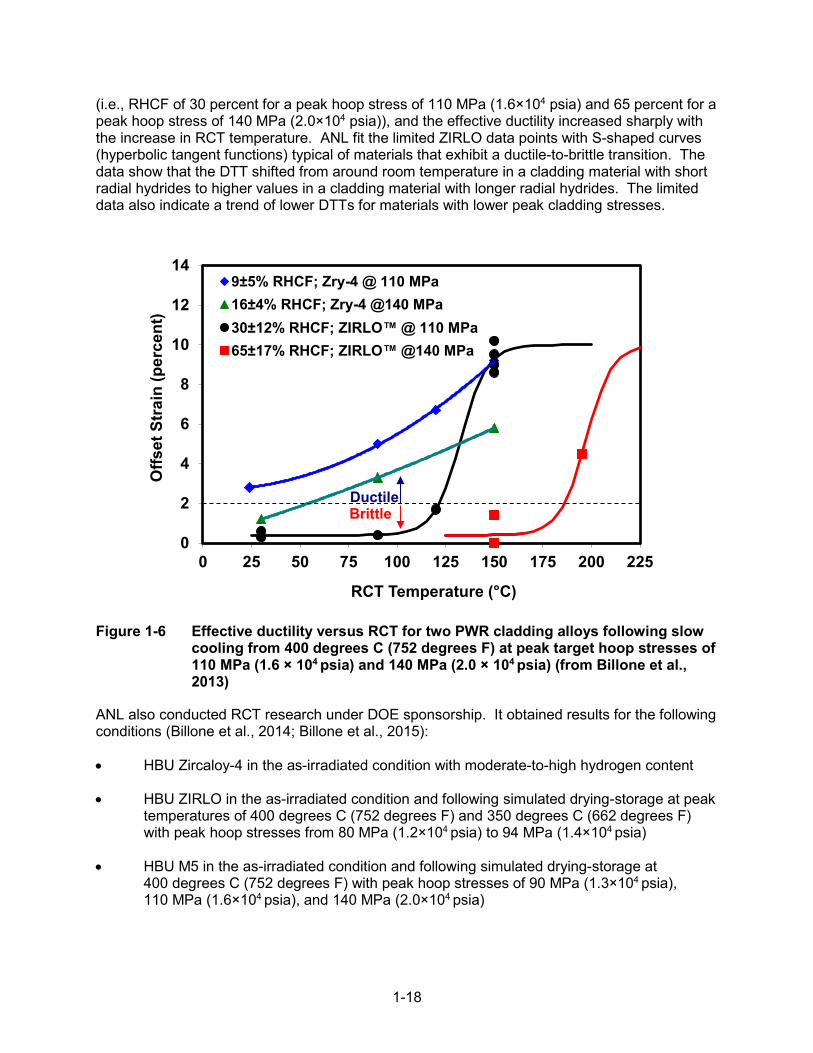
1-18
(i.e., RHCF of 30 percent for a peak hoop stress of 110 MPa (1.6×10⁴ psia) and 65 percent for a peak hoop stress of 140 MPa (2.0×10⁴ psia)), and the effective ductility increased sharply with the increase in RCT temperature. ANL fit the limited ZIRLO data points with S-shaped curves (hyperbolic tangent functions) typical of materials that exhibit a ductile-to-brittle transition. The data show that the DTT shifted from around room temperature in a cladding material with short radial hydrides to higher values in a cladding material with longer radial hydrides. The limited data also indicate a trend of lower DTTs for materials with lower peak cladding stresses.
Figure 1-6 Effective ductility versus RCT for two PWR cladding alloys following slow cooling from 400 degrees C (752 degrees F) at peak target hoop stresses of 110 MPa (1.6 × 10⁴ psia) and 140 MPa (2.0 × 10⁴ psia) (from Billone et al., 2013)
ANL also conducted RCT research under DOE sponsorship. It obtained results for the following conditions (Billone et al., 2014; Billone et al., 2015):
• HBU Zircaloy-4 in the as-irradiated condition with moderate-to-high hydrogen content
• HBU ZIRLO in the as-irradiated condition and following simulated drying-storage at peak temperatures of 400 degrees C (752 degrees F) and 350 degrees C (662 degrees F) with peak hoop stresses from 80 MPa (1.2×10⁴ psia) to 94 MPa (1.4×10⁴ psia)
• HBU M5 in the as-irradiated condition and following simulated drying-storage at 400 degrees C (752 degrees F) with peak hoop stresses of 90 MPa (1.3×10⁴ psia), 110 MPa (1.6×10⁴ psia), and 140 MPa (2.0×10⁴ psia)
0
2
4
6
8
10
12
14
0 25 50 75 100 125 150 175 200 225
Offs
et S
trai
n (p
erce
nt)
RCT Temperature (°C)
9±5% RHCF; Zry-4 @ 110 MPa16±4% RHCF; Zry-4 @140 MPa30±12% RHCF; ZIRLO™ @ 110 MPa65±17% RHCF; ZIRLO™ @140 MPa
Brittle Ductile

1-19
ANL conducted two additional tests with HBU ZIRLO cladding subjected to three drying cycles (e.g., from 400 degrees C (752 degrees F) to 300 degrees C (572 degrees F) and from 350 degrees C (662 degrees F) to 250 degrees C (482 degrees F)) at peak hoop stress of about 90 MPa (1.3×10⁴ psia) (Billone et al., 2014; Billone et al., 2015). The results suggest that multiple drying cycles have no effect on the length of radial hydrides or the DTT at this low stress level. Figures 1-7 through 1-9 show results for Zircaloy-4, ZIRLO, and M5 in both as-irradiated and hydride-reoriented condition following cooling from 400 degrees C (752 degrees F).
Figure 1-7 Ductility data, as measured by RCT, for as-irradiated Zircaloy-4 and Zircaloy-4 following cooling from 400 degrees C (752 degrees F) under decreasing internal pressure and hoop stress conditions (from Billone et al., 2013)
0
2
4
6
8
10
12
14
0 25 50 75 100 125 150 175 200 225
Offs
et S
trai
n (p
erce
nt)
RCT Temperature (°C)
300±15 wppm H640±140 wppm H520±90 wppm H615±82 wppm H
BrittleDuctile
145 MPaat 400°C
113 MPaat 400°C
High Burnup Zircaloy-4
As-Irradiated
1-20
Figure 1-8 Ductility data, as measured by RCT, for as-irradiated ZIRLO and ZIRLO following cooling from 400 degrees C (752 degrees F) under decreasing internal pressure and hoop stress conditions (from Billone et al., 2013)
0
2
4
6
8
10
12
14
0 20 40 60 80 100 120 140 160 180
Offs
et S
trai
n (p
erce
nt)
RCT Temperature (°C)
530±70 wppm H535±50 wppm H530±115 wppm H480±131 wppm H385±80 wppm H
BrittleDuctile
111 MPaat 400°C
80 MPaat 400°C
High Burnup ZIRLOAs-Irradiated
89 MPaat 400°C

1-21
Figure 1-9 Ductility data, as measured by RCT, for as-irradiated M5 and M5 following cooling from 400 degrees C (752 degrees F) under decreasing internal pressure and hoop stress conditions (from Billone et al., 2013)
The staff recognizes the uncertainties associated with the ductility curve fits of ANL’s RCT data because of the limited number of data points. However, the limited results appear to support the following general conclusions: (1) the DTT generally increases with increasing hoop stresses (i.e., the ductility transition shifts to higher cladding temperature), (2) both the susceptibility to radial hydride precipitation and ductility changes depend on cladding type and initial hydrogen content, and (3) depending on the cladding and test conditions, the DTT can occur at temperatures in the range of 20 degrees C (68 degrees F) to 185 degrees C (365 degrees F). The results for as-irradiated Zircaloy-4 are consistent with studies by Wisner and Adamson (1998) and Bai et al. (1994). The staff considered these conclusions when defining limiting conditions for inducing radial hydrides and conducting fatigue and bending testing of HBU SNF (see Chapter 2).
It is important to note that the DTT is not an intrinsic property of a cladding alloy material with a given homogeneous composition, in the classical metallurgical sense, but it is highly dependent on the composite microstructure (hydride-zirconium matrix, as determined by reactor operating conditions), fabrication conditions (degree of cold working, recrystallization), and the operating conditions during drying-transfer, storage, or transportation (peak cladding temperature, peak hoop stress, temporal cooling profile). Further, the DTT was established based on an arbitrarily defined performance criterion (e.g., 50-percent cladding through-wall crack before 2-percent offset strain deformation) and based on a limited number of data points for each cladding alloy. It is also important to note that, because of the radial and axial temperature gradients in a DSS or transportation package, it is highly likely that only a small fraction of the cladding in a given
0
2
4
6
8
10
12
14
0 25 50 75 100 125 150 175 200 225
Offs
et S
trai
n (%
)
RCT Temperature (°C)
76±5 wppm H58±15 wppm H (90 MPa)72±10 wppm H (111 MPa)94±4 wppm H (142 MPa)
142 MPa at 400°C
111 MPaat 400°C
Ductile
Brittle
High Burnup M5
As-Irradiated
90 MPaat 400°C

1-22
assembly will reach high enough temperatures and hoop stresses to have sufficient hydridereorientation during cooling. Those hotter axial locations of the cladding will likely be the last to reach a DTT during transport.
1.5.5 Staff’s Assessment of Ring Compression Testing Results
As previously discussed, the staff has long expected that hydride reorientation would not compromise cladding integrity caused by fuel rod bending (i.e., bending expected during normal conditions of storage and transport), since the principal tensile stress field associated with rod bending caused by lateral inertia loads is parallel to both radial and circumferential hydrides (Tang et al., 2015). The staff has considered that any reduced cladding ductility caused by hydride reorientation could only potentially compromise the analyzed fuel configuration for pinch loads experienced during drop accident scenarios, if the fuel had significantly cooled during the transportation period. More specifically, the staff had expressed concern that reorientation could decrease failure stresses and strains in response to transportation-induced pinch loads during a 9-m (30-ft) drop scenario as a result of rod-to-grid spacer contact, rod-to-rod contact, or rod-to-basket contact.
To address the concern of reduced ductility during drop accidents, the staff previously proposed varied approaches to demonstrate that the failure limits for as-irradiated cladding (as used in the design-basis structural evaluations) would continue to be adequate even if hydride reorientation occurred. One of these approaches was based on justifying an RCT-measured DTT for each cladding alloy in the proposed fuel contents and demonstrating that the minimum cladding temperature remained above the RCT-measured DTT for the entire duration of transport. The minimum cladding temperature assumed for transport operations would need to be bounding to the contents upon consideration of the cold temperature requirement in 10 CFR 71.71(c)(2) (i.e., an ambient temperature of -40 degrees C (-40 degrees F) in still air and shade. If these conditions were met, then mechanical properties of the as-irradiated cladding material (i.e., material that did not account for the precipitation of radial hydrides) would be considered adequate for the structural evaluation.
As an alternative approach, if the applicant could not reasonably demonstrate that sections of the fuel cladding remained above the RCT-measured DTT during the entire duration of transport, the staff proposed that the application provide additional safety analyses assuming hypothetical reconfiguration of the HBU fuel contents. If neither of these two approaches is satisfactory for demonstrating compliance with 10 CFR Part 71 regulations, then the staff would expect that the fuel would be canned and classified as damaged.
Since proposing these approaches, the staff has reevaluated whether results from RCT of defueled specimens are accurately representative or if they are overly conservative relative to the actual hoop-loading conditions experienced by the fuel during a 9-m (30-ft) drop. During RCT, the circumferential (hoop) tensile bending stress is perpendicular to the plane of the radial hydrides, which is different from the relative orientation of the applied stress and hydrides under axial tensile bending where the longitudinal (axial) tensile bending stress is always parallel to the plane of both the circumferential and radial hydrides. The orientation of the tensile stress is expected to make a difference in the response of the cladding.
The RCT defined a DTT used to determine cladding failure caused by pinch loads. However, it is necessary to consider the importance of this failure mode in the determination of cladding integrity in the event of a drop accident. To do this, the RCT must be examined for what it is, a test in which diametrically opposed, concentrated compressive forces are applied to a fuel cladding longitudinal segment that does not contain fuel. During NCT and HAC side drops, the

1-23
fuel rod is loaded by lateral inertia loads that are resisted by distributed loads applied to the bottom of the rod at the flexible grid spacer springs (Figure 1-10). Further, the inertia load in the rod is transferred to the grid spacer support as a shear force in the cladding (and pellets), not as a concentrated load at the top of the rod.
Single Rod Model
Single Assembly Model
Figure 1-10 Geometric models for spent fuel assemblies in transportation packages (reproduction, in part, of Figure 10 from Sanders et al., 1992)
Given that the forces and displacements in the RCT are measurably different from the actual forces and displacements applied to the rod at the grid spacer support, it is not likely that the pinch mode of failure will play a significant role in undermining cladding integrity. To quantify the difference between these loading cases, the staff analyzed two ring segments for different loading conditions and the change in diameter calculated. In the first case, the ring segment was loaded by diametrically opposed compressive forces like those of RCT (Case 1, Table 17, Roark and Young (1975)). In the second case, the ring segment was supported at the bottom by a concentrated reaction and loaded by a downward load uniformly distributed around the circumference of the ring to simulate a shear loading as in a side drop (Case 13, Table 17, Roark and Young (1975)). In both cases, the total applied load was the same. The ratio of the change in diameter of the second case to the first case is 0.48. Thus, the diametrically opposed compressive forces produced more than twice the displacement when compared to the circumferentially distributed load. In addition, the gap at the pellet-cladding interface is generally closed at rod segments irradiated to high burnup because of pellet expansion during irradiation. The closed gap will limit the deflection of the cladding before experiencing mechanical resistance by the pellet. Thus, the staff considers that, under a pinch load, ovalization of the cladding cross-section is very unlikely, and any circumferential bending stress that does exist will be negligible. The RCT conducted to date does not account for the rod’s resistance to ovalization provided by the pellet.
Based on the RCT load-displacement data, ANL defined the effective cladding ductility (i.e., the transition between ductile and brittle behavior) to be a 2-percent offset strain before a crack extending through more than 50 percent of the cladding wall (Billone et al., 2013). If the strains experienced during RCT’s diametrically opposed loads result in twice those that would be experienced during lateral inertial loads, then the DTT is likely to shift to lower temperatures (potentially room temperature or lower). Therefore, the staff considers that the DTT defined by RCT experiments is overly conservative and not representative of actual fuel and stress conditions during NCT and HAC drop scenarios. The DOE is planning to sponsor a research program in which 25 HBU fuel rods will undergo testing to determine their

1-24
characteristics, material properties, and rod performance following representative drying-transfer and cooldown (Hanson et al., 2016). The staff expects that material property testing conducted under this program will confirm that the cladding displacements experienced by fueled cladding specimens during RCT will be lower than those measured in defueled specimens and that ductility during accident drop scenarios is not compromised. Results from the static and fatigue bend testing discussed in Chapter 2 further justify the staff’s conclusion that the pellet imparts structural support to the mechanical performance of the fuel rod, as previously evaluated by finite element analysis (Machiels, 2005).
2-1
2 ASSESSMENT OF STATIC BENDING AND FATIGUE STRENGTH RESULTS ON HIGH BURNUP SPENT NUCLEAR FUEL
2.1 Introduction
The sealed canister, cask cavity, or overpack generally serves as the primary barrier in a dry storage system (DSS) or transportation package for protecting against the release to the atmosphere of radioactive solid particles or gases from the loaded spent nuclear fuel (SNF). The spent fuel cladding also serves as a confinement or containment barrier for preventing radioactive solid particles and fission gasses from being released into the interior cavity of the DSS or transportation package. The cladding not only provides a barrier for preventing the release of radioactive material but also prevents fuel reconfiguration during storage and transport operations. Therefore, the integrity of the cladding is an essential component of a defense-in-depth strategy to protect the public health and safety.
Until recently, research to understand the structural behavior of spent fuel rods during transportation and storage has focused entirely on obtaining mechanical and strength properties of spent fuel cladding. As a result, the flexural rigidity and structural response of fuel rods during normal and accident events have been based on the mechanical and strength properties of only the cladding. The contribution of the fuel pellets to increasing the flexural rigidity of the rod has been neglected. However, recent research discussed in NUREG/CR-7198, Revision 1, “Mechanical Fatigue Testing of High-Burnup Fuel for Transportation Application,” issued October 2017 (NRC, 2017), on the static bending response and fatigue strength of fuel rods considered as a composite system of cladding and fuel pellets, has begun to provide some of the necessary data to allow a more accurate assessment of the structural behavior of the composite fuel rod system under normal conditions of transport (NCT) and hypothetical accident conditions (HAC), as well as DSS drop and tipover events.
The following discussion assesses the results from the U.S. Nuclear Regulatory Commission’s (NRC’s) independent test program on the mechanical performance of high burnup (HBU) SNF under static and dynamic bending conditions. Section 2.2 discusses the available fuel rod composite static and dynamic bending empirical data and its acquisition. Section 2.3 describes the application of the static bending empirical data for the evaluation of design-basis drop accidents in storage and transportation and the development of a composite rod analytical model. Section 2.4 discusses the application of the dynamic bending empirical data to the evaluation of fatigue during transportation.
2.2 Cyclic Integrated Reversible Fatigue Tester
In 2009, the NRC tasked Oak Ridge National Laboratory (ORNL) with investigating the flexural rigidity and fatigue life of HBU SNF (NRC, 2017). The testing was designed to evaluate the fuel rod as a composite system, including the presence of intact fuel inside the cladding and any pellet/cladding bonding effects. The project proceeded in two phases. Phase I involved testing HBU SNF in the as-irradiated state, where hydrides are expected to be predominantly in the circumferential-axial orientation. Phase II involved testing HBU SNF segments subjected to a treatment designed to reorient the hydrides in the cladding to be predominantly in the radial-axial orientation. All testing was conducted at room temperature, which is expected to result in the most limiting cladding ductility.

2-2
In response to the NRC tasking, in 2011, ORNL proposed a bending fatigue system for testing HBU SNF rods. The system consists of a U-frame equipped with load cells for imposing pure bending loads on the SNF rod test specimen and measuring the in situ curvature of the fuel rod during bending using a setup of three linear variable differential transformers (LVDTs) (Figure 2-1). Pure bending is a condition of stress in which a bending moment is applied to a beam without the simultaneous presence of axial, shear, or torsional forces.

2-3
Figure 2-1 Horizontal layout of ORNL U-frame setup (top), rod specimen and three LVDTs for curvature measurement (middle), and front view of CIRFT installed in ORNL hot cell (bottom) (Figure 4 from NUREG/CR-7198, Revision 1 (NRC, 2017))
SNF rod segment
End-blocks
LVDT clamp
Three LVDTs for curvature measurement
Rod specimen
Rigid arms
Connecting plates
Universal testing machine links
Load cell
(middle)
(bottom)
(top)

2-4
On August 19, 2013, a testing system was installed in a hot cell at ORNL’s Irradiated Fuels Examination Laboratory and formally named the “cyclic integrated reversible-bending fatigue tester” (CIRFT). After tuning of the test system and performance of benchmark testing in September 2013, testing began on HBU SNF rod segments with intact Zircaloy-4 cladding irradiated in the H.B. Robinson Steam Electric Plant (HBR), Unit 2. The rod-average fuel burnup for the 15 × 15 pressurized-water reactor (PWR) assembly was 67 GWd/MTU. Table 2-1 identifies the burnup for each tested rod segment.
Table 2-1 Specifications of rod specimens used in NRC-sponsored HBU SNF test program (reproduced in part from Table 2, NUREG/CR-7198, Revision 1 (NRC, 2017))
Specimen Label Burnup
(GWd/MTU) Estimated Hydrogen of Span
(wppm)
Static Tests
S1 66.8 550–750
S2 66.5 360–550
S3 66.5 550–750
S4 66.5 550–750
Dynamic Tests
D0 66.5 360–550
D1 63.8 550–750
D2 63.8 550–750
D3 66.5 550–750
D4 66.5 360–550
D5 66.5 360–550
D6 66.5 550–750
D7 66.5 550–750
D8 66.8 550–750
D9 66.5 550–750
D10 66.8 550–750
D11 63.8 550–750
D12 63.8 550–750
D13 66.5 750–800
D14 66.5 750–800
D15 66.5 750–800
HR1 63.8 360–400
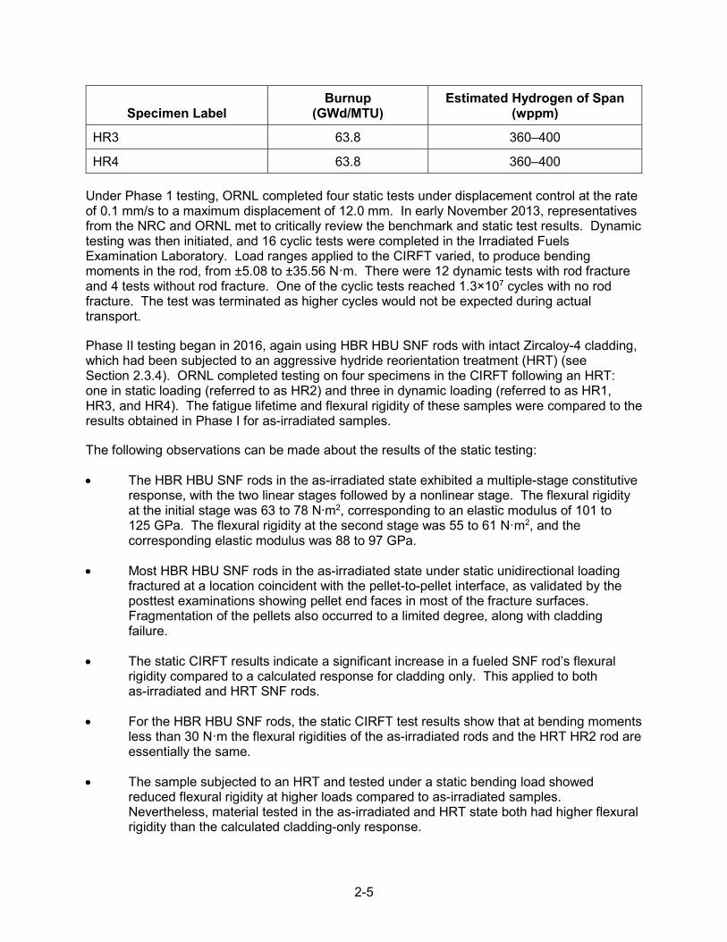
2-5
Specimen Label Burnup
(GWd/MTU) Estimated Hydrogen of Span
(wppm)
HR3 63.8 360–400
HR4 63.8 360–400
Under Phase 1 testing, ORNL completed four static tests under displacement control at the rate of 0.1 mm/s to a maximum displacement of 12.0 mm. In early November 2013, representatives from the NRC and ORNL met to critically review the benchmark and static test results. Dynamic testing was then initiated, and 16 cyclic tests were completed in the Irradiated Fuels Examination Laboratory. Load ranges applied to the CIRFT varied, to produce bending moments in the rod, from ±5.08 to ±35.56 N·m. There were 12 dynamic tests with rod fracture and 4 tests without rod fracture. One of the cyclic tests reached 1.3×10⁷ cycles with no rod fracture. The test was terminated as higher cycles would not be expected during actual transport.
Phase II testing began in 2016, again using HBR HBU SNF rods with intact Zircaloy-4 cladding, which had been subjected to an aggressive hydride reorientation treatment (HRT) (see Section 2.3.4). ORNL completed testing on four specimens in the CIRFT following an HRT: one in static loading (referred to as HR2) and three in dynamic loading (referred to as HR1, HR3, and HR4). The fatigue lifetime and flexural rigidity of these samples were compared to the results obtained in Phase I for as-irradiated samples.
The following observations can be made about the results of the static testing:
• The HBR HBU SNF rods in the as-irradiated state exhibited a multiple-stage constitutiveresponse, with the two linear stages followed by a nonlinear stage. The flexural rigidityat the initial stage was 63 to 78 N∙m2, corresponding to an elastic modulus of 101 to125 GPa. The flexural rigidity at the second stage was 55 to 61 N·m2, and thecorresponding elastic modulus was 88 to 97 GPa.
• Most HBR HBU SNF rods in the as-irradiated state under static unidirectional loadingfractured at a location coincident with the pellet-to-pellet interface, as validated by theposttest examinations showing pellet end faces in most of the fracture surfaces.Fragmentation of the pellets also occurred to a limited degree, along with claddingfailure.
• The static CIRFT results indicate a significant increase in a fueled SNF rod’s flexuralrigidity compared to a calculated response for cladding only. This applied to bothas-irradiated and HRT SNF rods.
• For the HBR HBU SNF rods, the static CIRFT test results show that at bending momentsless than 30 N·m the flexural rigidities of the as-irradiated rods and the HRT HR2 rod areessentially the same.
• The sample subjected to an HRT and tested under a static bending load showedreduced flexural rigidity at higher loads compared to as-irradiated samples.Nevertheless, material tested in the as-irradiated and HRT state both had higher flexuralrigidity than the calculated cladding-only response.

2-6
• The static CIRFT test result for HR2 supports the pretest expectation (hypothesis) thatbecause the tensile bending stress in the cladding is parallel to the plane of both theradial and circumferential hydrides, the presence of radial hydrides would notsignificantly alter the flexural response when compared to the case where onlycircumferential hydrides are present.
• The CIRFT test methodology and the methodology developed in this NUREG forcalculating cladding stress and strain apply to all current commercial power fuel rodtypes, and the use of cladding-only properties to calculate cladding stress and strain isalways conservative.
• The HBR HBU SNF rods in the as-irradiated state survived static unidirectional bendingto a maximum curvature of 2.2 to 2.5 m-1, or a maximum moment of 85 to 87 N∙m. TheCIRFT device displacement capacity bounded the maximum static unidirectionalbending values. The maximum equivalent strain was 1.2 to 1.4 percent.
• Based on the static CIRFT test results, the lower-bound safety margin (SM) against fuelrod failure during an HAC side-drop event is 2.35, assuming the side drop imparts a 50gload to the package body.
The following observations can be made about the results of the dynamic testing:
• The fatigue life of HBR HBU SNF rods in the as-irradiated state in the cyclic testsdepended on the level of loading. Under loading with moments of ±8.20 to ±33.67N∙m—namely, ±0.066 to ±0.335 percent strain—the fatigue life ranged from 5.5×10³ to2.3×106 cycles.
• The ε-N curve of the HBR HBU SNF rods in the as-irradiated state can be described bya power function of y = 3.839·x-0.298, wherexxis the number of cycles to failure, and y isthe strain amplitude (percent).
• The failure of HBR HBU SNF rods under cyclic loading often occurred nearpellet-to-pellet interfaces.
The following sections describe an assessment by the NRC staff of ORNL’s CIRFT data and present conclusions as to the expected structural performance of HBU SNF during dry storage and transportation.
2.3 Application of the Static Test Results
When evaluating the HAC 9-m (30-ft) drop test, as required by Title 10 of the Code of Federal Regulations (10 CFR) 71.73(c)(1), two drop orientations produce distinctly different structural behaviors in the fuel rods. These orientations are the side drop and the end drop (Figure 2-2). In the side drop, lateral inertia loads are applied to the fuel rods, and bending dominates the structural response. In the end drop, axial compression and the associated buckling of the fuel rod dominate the structural response. For a side-drop event, the CIRFT static bending test results from NUREG/CR-7198, Revision 1 (NRC, 2017), can be directly applied to quantify the fuel rod structural response. For the end drop, the presence of axial compression in the fuel rod represents a force component that was not present in the CIRFT static bending tests. This,
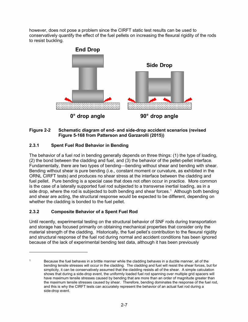
2-7
however, does not pose a problem since the CIRFT static test results can be used to conservatively quantify the effect of the fuel pellets on increasing the flexural rigidity of the rods to resist buckling.
Figure 2-2 Schematic diagram of end- and side-drop accident scenarios (revised Figure 5-168 from Patterson and Garzarolli (2015))
2.3.1 Spent Fuel Rod Behavior in Bending
The behavior of a fuel rod in bending generally depends on three things: (1) the type of loading, (2) the bond between the cladding and fuel, and (3) the behavior of the pellet-pellet interface.Fundamentally, there are two types of bending—bending without shear and bending with shear.Bending without shear is pure bending (i.e., constant moment or curvature, as exhibited in theORNL CIRFT tests) and produces no shear stress at the interface between the cladding andfuel pellet. Pure bending is a special case that does not often occur in practice. More commonis the case of a laterally supported fuel rod subjected to a transverse inertial loading, as in aside drop, where the rod is subjected to both bending and shear forces.1 Although both bendingand shear are acting, the structural response would be expected to be different, depending onwhether the cladding is bonded to the fuel pellet.
2.3.2 Composite Behavior of a Spent Fuel Rod
Until recently, experimental testing on the structural behavior of SNF rods during transportation and storage has focused primarily on obtaining mechanical properties that consider only the material strength of the cladding. Historically, the fuel pellet’s contribution to the flexural rigidity and structural response of the fuel rod during normal and accident conditions has been ignored because of the lack of experimental bending test data, although it has been previously
1 Because the fuel behaves in a brittle manner while the cladding behaves in a ductile manner, all of the bending tensile stresses will occur in the cladding. The cladding and fuel will resist the shear forces, but for simplicity, it can be conservatively assumed that the cladding resists all of the shear. A simple calculation shows that during a side-drop event, the uniformly loaded fuel rod spanning over multiple grid spacers will have maximum tensile stresses caused by bending that are more than an order of magnitude greater than the maximum tensile stresses caused by shear. Therefore, bending dominates the response of the fuel rod, and this is why the CIRFT tests can accurately represent the behavior of an actual fuel rod during a side-drop event.

2-8
evaluated by finite element analysis to improve the composite rod’s mechanical response (Machiels, 2005)). Recent research sponsored by the NRC on the static bending response and fatigue strength of HBU SNF rods with the presence of the fuel pellets has provided data necessary to more accurately assess the structural behavior of the composite HBU SNF rod system (NRC, 2017). These results have provided an opportunity for the NRC to assess the conservatism associated with assuming only the mechanical strength of the cladding in the design-basis structural evaluations of DSSs and transportation packages.
A spent fuel rod is considered to be a composite system consisting of cladding and fuel. The structural response of the fueled-rod composite system is usually explained as follows.
On one hand, if the pellet is not bonded to the cladding, displacement compatibility is not maintained at the pellet-cladding interface, and composite action does not occur. In this case, the flexural rigidity is given by the following equation, where the fuel is assumed to be a homogeneous solid:
EI = EcIc + EpIp (Eq. 2-1)
That is, the flexural rigidity is equal to the sum of the individual flexural rigidities of the cladding and fuel pellets, where Ec and Ic are the elastic modulus and moment of inertia of the cladding, respectively, and Ep and Ip are the elastic modulus and moment of inertia of the pellet, respectively.
On the other hand, if the pellet is bonded to the cladding, displacement compatibility is maintained at the pellet-cladding interface and composite action occurs. In this case, the flexural rigidity is calculated by transforming the pellet properties into equivalent cladding properties (i.e., by multiplying the pellet moment of inertia by Ep/Ec). This is the same technique commonly used for reinforced concrete (Winter and Nelson, 1979).
The remainder of this section explains the behavior of composite systems, in general, and then specifically addresses the spent fuel rod composite system by assuming the fuel material is a homogeneous uncracked solid. To ensure a full understanding of the unique behavior of this composite system, the bending behavior of a more general composite beam will be discussed. Consider a composite concrete and steel I-beam where a concrete slab, rectangular in cross-section, is poured onto the top flange of a steel I-beam (Figure 2-3). This type of composite beam is commonly found in highway bridge construction. Assume the concrete and steel beam are simply supported and a concentrated load is applied at midspan. If the concrete slab and steel beam are not bonded to each other, no shear transfer takes place at the interface between the steel and concrete, and the flexural rigidity (EI) is equal to the sum of the individual flexural rigidities of the concrete slab and steel beam taken separately.

2-9
Figure 2-3 Typical composite construction of a bridge
On the other hand, if the concrete slab and steel beam are bonded to each other (typically done using shear studs), then shear transfer takes place, and the concrete slab and steel beam act as a composite section. In this case, the flexural rigidity of the composite beam will be significantly greater than the sum of the individual flexural rigidities taken separately. This example of a concrete slab bonded to the top flange of a steel beam illustrates the behavior of a composite system where the centers of gravity of each of the two components (i.e., concrete slab and steel I-beam) are not coincident.
For the special case where the centers of gravity (cgs) of the two components are coincident, the flexural rigidity of the composite section is always equal to the sum of the flexural rigidities of the individual components whether the components are bonded or unbonded. The following example illustrates this concept. Consider a simply supported span composed of two beams, each with a rectangular cross-section 2 inches wide, and 6 inches deep (i.e., a “2 × 6”). Let the 2 × 6’s be configured one on top of the other, where the cgs are not coincident as shown in Figure 2-4a. If the beams are unbonded, the moment of inertia of the section (I = bh3/12 per beam), is equal to 2 × 2 inches × (6 inches)3/12 = 72 inches4. If they are bonded, then the moment of inertia of the section is equal to 2 inches × (2 × 6 inches)3/12 = 288 inches4.

2-10
Figure 2-4 Influence of cg position on composite beam stiffness: (a) cgs are not coincident, (b) cgs are coincident
Now let the 2 × 6’s be configured as shown in Figure 2-4b, where the cgs are aligned on the same bending axis (i.e., they are “coincident”). If they are unbonded, the moment of inertia of the section is 2 × 2 inches × (6 inches)3/12 = 72 inches4. If they are bonded, I = 2 × 2 inches × (6 inches)3/12 = 72 inches4. Thus, when the cgs of the 2 × 6’s are “coincident,” the flexural rigidity of the beam is the sum of the individual flexural rigidities of the 2 × 6’s regardless of whether the 2 × 6’s are bonded or unbonded. While previously unrecognized, this is the situation with a spent fuel rod, in which the cladding cylindrical tube and the spent fuel cylindrical solid section have coincident cgs. Thus, for a spent fuel rod, where the fuel is assumed to be a homogeneous solid, the flexural rigidity is given by Equation 2-1, regardless of whether the fuel is bonded to the cladding. All moments of inertia are taken about the neutral axis of the fuel rod.
2.3.3 Calculation of Cladding Strain from CIRFT Static Bending Data
The objective of this section is to develop a simple methodology that uses the CIRFT static test data for fully fueled composite spent fuel rods to evaluate spent fuel rod cladding strain. The methodology presented here to determine cladding response (i.e., cladding stresses and strains) is based on a set of assumptions that are consistent with those made by ORNL in its presentation of CIRFT results in NUREG/CR-7198, Revision 1 (NRC, 2017). These assumptions, which are discussed in greater detail below, are based on the integrated average response of the fuel rod along its gauge length. Further, the methodology recognizes the actual behavior of the fuel rod where the fuel is no longer a homogeneous solid, as previously discussed in Section 2.3.2 (i.e., the fuel pellets crack at their interface during bending).
The fuel rod composite system (Figure 2-5) is composed of cladding, which exhibits ductile behavior, and the fuel pellet, which exhibits brittle behavior. In a spent fuel rod subject to bending, where the fuel is a homogeneous solid, the neutral axis is at the center of the rod cross-section, provided that the brittle fuel does not crack in tension. Once the fuel cracks, the neutral axis will shift toward the compression side of the cross-section. The ORNL tests show that the region of the fuel weakest in tension is at the pellet-pellet interface. When the pellet-pellet interface cracks, the tensile stress in the cladding at the crack face will increase

2-11
significantly. On either side of the crack face, the shear stress between the cladding and fuel is high and decreases parabolically with distance from the crack (Figure 2-6). The high tensile stress in the cladding at the crack face also decreases parabolically with distance from the crack. Thus, the cladding tensile stresses will vary significantly along the length of the rod; they are highest at the crack face and much lower away from the crack face. Even though this behavior is known to occur, only the average tensile bending stress can be calculated from the static test results because the measured curvature is the integrated average curvature over the measurement length (gauge length) of the rod.
Figure 2-5 Images of cladding-pellet structure in HBU SNF rod (66.5 GWd/MTU, 40–70 µm oxide layer, 500 wppm hydrogen content in Zircaloy-4): (a) overall axial cross-section and (b) enlarged area (revised Figure 33 fromNUREG/CR-7198, Revision 1 (NRC, 2017))

2-12
Figure 2-6 Approximate extreme fiber tensile stresses between pellet-pellet crack
The LVDTs measure displacements at three locations on the test specimen. The distance between the first and third probes is the gauge length of the specimen. Because the bending moment is constant along the gauge length, it would be expected that several pellet-pellet interface cracks would develop within the gauge length. That being the case, the cladding tensile stresses and strains along the gauge length will vary significantly. However, this variation in strain along the gauge length was not, and cannot, be measured. What was measured is the average curvature along the gauge length. Therefore, only the average tensile strain (i.e., the smeared tensile strain) can be calculated. The average tensile strain, ε, along the gauge length is equal to the curvature, κ, multiplied by the distance to the neutral axis, ymax:
ε = κ · ymax (Eq. 2-2)
However, ymax can vary significantly along the gauge length. At a section where the fuel has not cracked, ymax is equal to the outer radius, r. At a pellet-pellet interface crack, ymax would be greater than the radius but less than the diameter. However, because the measured and calculated results are averages over the gauge length, a convention must be adopted for calculating cladding strain, and this convention must be consistently applied throughout. The convention used in NUREG/CR-7198, Revision 1 (NRC, 2017), and adopted in this document to convert average curvature to average cladding strain is to assume that the distance from the tensile face of the cladding to the neutral axis is equal to the outside radius, r.
Average cladding tensile stress, σ, should be calculated directly from average cladding strain using the following equation:
σ = ε · Ec (Eq. 2-3)
Equation 2-3 provides a consistent and compatible relationship between stress and strain.

2-13
2.3.4 Calculation of Cladding Strain Using Factored Cladding-Only Properties
The following discussion describes a methodology that can be easily used to calculate the cladding tensile strain and stress and fuel rod flexural rigidity using only cladding-only properties. Section 4.2.2 of NUREG/CR-7198, Revision 1 (NRC, 2017), presents analyses comparing the measured flexural rigidity from the CIRFT static test results to the calculated flexural rigidity values using the validated cladding-only mechanical property models developed by Pacific Northwest National laboratory (PNNL) (Geelhood et al., 2008). The purpose of the comparison was to investigate the effect of fuel pellets on the fuel rod’s flexural rigidity and cladding strain.
Figure 2-7 Comparison of CIRFT static bending results with calculated PNNL moment curvature (flexural rigidity) derived from cladding-only stress-strain curve (reproduction of Figure 22 from NUREG/CR-7198, Revision 1 (NRC, 2017)). S1, S2, S3, and S4 represent the experimental results for HBR HBU SNF as-irradiated specimens; HR2 represents the experimental results for HBR HBU SNF hydride-reoriented specimens; and PNNL represents the results calculated using the validated cladding-only mechanical property models developed by PNNL (from Geelhood et al., 2008).
The CIRFT static test results plotted in Figure 2-7 show the moment-curvature response of the four HBR HBU SNF as-irradiated specimens S1, S2, S3, and S4 and the hydride-reoriented specimen HR2. The loading portion of the moment-curvature response begins at 0 N·m and reaches a maximum at about 80 N·m, at which point the specimens begin to unload. The moment-curvature responses of the four HBR HBU SNF as-irradiated specimens during loading were similar up to a moment of 35 N·m. They are characterized by two distinct linear responses, EI1 and EI2, followed by a nonlinear response during the loading and a linear response upon unloading (EI3) (Figure 2-8).
Also shown in Figure 2-7 is the cladding-only moment-curvature loading curve constructed using the PNNL cladding-only mechanical property models. The static test results for both

2-14
as-irradiated and hydride-reoriented specimens show much higher bending moment resistance during loading compared to the PNNL cladding-only data. The slopes, EI1 and EI2, of the four HBU fuel rods are greater than the slope of the PNNL data for the cladding-only rod.
Figure 2-8 Characteristic points on moment-curvature curve. A, B, C, and D are points on the curve. EI1 is the slope of the loading curve between 0 and A. EI2 is the slope of the loading curve between A and B. EI3 is the slope of the unloading curve between D and 0 (reproduction of Figure 21 from NUREG/CR-7198, Revision 1 (NRC, 2017)). The cladding-only moment-curvature loading curve constructed using the PNNL cladding-only mechanical property models is not shown.
Figure 2-7 also shows that at bending moments during loading less than 35 N·m, the flexural rigidities of the four as-irradiated rods, which have only circumferential hydrides, and HR2, which has both circumferential and radial hydrides, are essentially the same. This result supports the pretest expectation that, because the bending tensile stress in the cladding is parallel to the plane of both the radial and circumferential hydrides, the presence of radial hydrides would not significantly alter the flexural response from the case where only circumferential hydrides are present. The results of tests currently being conducted by the U.S. Department of Energy (DOE) will further confirm this hypothesis as it applies to other cladding types.
In the CIRFT static test results for HBR HBU SNF rods shown in Figure 2-7, no failures occurred. The lower-bound maximum moment achieved in the tests is approximately 80 N·m. In addition, it is important to note that a bending moment of 80 N·m is significantly greater than the bending moment an HBR HBU SNF rod will experience during an HAC 9-m (30-ft) side drop (see Section 2.3.5.1). This means that fuel rod integrity is expected to be maintained during an HAC drop scenario, and therefore, fuel rod reconfiguration is very unlikely.

2-15
For the as-irradiated HBR HBU SNF rods, Table 2-2 shows that in the EI1 region of the moment-curvature results, the average flexural rigidity is 2.66 (i.e., 71.58 N·m2/26.93 N·m2) times greater than the cladding-only case, and in the EI2 region, the average flexural rigidity is 2.16 (i.e., 58.10 N·m2/26.93 Nm 2) times greater than the cladding-only case. For the hydride-reoriented fuel rod, HR2, Table 2-2 shows that in the EI1 region, the average flexural rigidity is 2.33 (i.e., 62.77 N·m2/26.93 N·m2) times greater than the cladding-only case, and in the EI2 region, the average flexural rigidity is 1.54 (i.e., 41.52 N·m2/26.93 N·m2) times greater than the cladding-only case.
Table 2-2 Comparison of average flexural rigidity results between CIRFT static testing and PNNL cladding-only data (from “Validated Mechanical Property Models” in Geelhood et al., 2008)
Test Specimen EI1 (N·m2) EI2 (N·m2) EI3 (N·m2) EI1/
EIcladding
EI2/ EIcladding
As-Irradiated (S1, S2, S3, and S4) 71.576 58.099 48.133 2.66 2.16
Hydride-Reoriented (HR2) 62.769 41.517 43.333 2.33 1.54
Cladding-Only (Validated PNNL Models)
26.933 26.933 -
Table 2-3 Characteristic points and quantities based on moment-curvature curves (reproduction, in part, of Table 4 from NUREG/CR-7198, Revision 1 (NRC, 2017))
Spec label EI1
(N∙m2) EI2
(N∙m2) EI3
(N∙m2) κA
(m-1) κB
(m-1) κC
(m-1) κD
(m-1) MA
(N∙m) MB
(N∙m) MC
(N∙m) MD
(N∙m)
S1 78.655 57.33 51.027 0.202 0.968 2.009 2.166 16.695 60.599 83.595 85.413
S2 73.016 60.848 52.699 0.32 1.009 2.001 2.154 20.18 62.133 85.914 87.294
S3 71.517 59.369 47.101 0.311 0.933 2.149 2.308 22.338 59.288 83.728 85.235
S4 63.117 54.849 41.704 0.503 0.862 2.329 2.507 28.54 48.244 81.656 85.02
As-irradiated Avg.
71.576 58.099 48.133 0.334 0.943 2.122 2.284 21.938 57.566 83.723 85.741
As-irradiated Std. Dev.
6.422 2.603 4.886 0.125 0.062 0.154 0.164 4.977 6.322 1.741 1.048
HR2 62.769 41.517 43.333 0.487 1.007 1.585 2.158 30.301 51.884 66.809 79.606
In developing a simplified methodology using cladding-only mechanical properties, the staff considers it conservative to use the flexural rigidity ratio from the EI2 data. More specifically, using the average minus two standard deviations of the EI2 data from Table 2-3 is 52.90 N·m2 (i.e., 58.10 N∙m2 – 2(2.60 N∙m2)), which results in an EI2 ratio of an HBU fuel rod to a cladding-only rod of 1.96 (i.e., 52.90 N∙m2/26.93 N∙m2). The average minus two standard deviations has a 98-percent exceedance probability, which means there is a 98-percent chance that the actual value of the EI ratio will be greater than 1.96. To account for the effects of

2-16
hydride reorientation, this result is reduced by 0.713 (i.e., 1.54/2.16), which is the ratio of the reoriented hydride results to the as-irradiated results that were calculated in the previous paragraph. Multiplying 1.96 by 0.713 results in a factor of 1.40. However, recognizing the limited test data available for calculating the 1.40 factor, the factor has been further reduced to 1.25 to account for the additional uncertainty associated with using limited data. Thus, for the purpose of calculating lateral displacements in the simplified methodology, the flexural rigidity of the HBU fuel rod is equal to the flexural rigidity of the cladding-only rod multiplied by the factor 1.25:
(EI)HBU rod = 1.25 ∙ (EI)clad only (Eq. 2-4)
The curvature, κ, of the HBU fuel rod is given by:
κ = M/(EI)HBU rod (Eq. 2-5)
or:
κ = M/[1.25 · (EI)clad only] (Eq. 2-6)
where M is the bending moment in the rod.
The tensile strain is given by:
ε = κ · ymax (Eq. 2-7)
where ymax is equal to the outer radius, r, of the rod, and the maximum tensile stress is given by:
σ = ε · Ec (Eq. 2-8)
The methodology described above for using cladding-only properties to calculate cladding strains while accounting for the increased flexural rigidity imparted by the fuel pellet can also be applied to cladding alloys other than Zircaloy-4. Once CIRFT static bending results for other HBU SNF rods (i.e., ZIRLO™ (ZIRLO)-clad and M5® (M5)-clad rods) are obtained under planned DOE-sponsored research (Hanson et al., 2016), this methodology can be replicated to obtain a numerical factor that allows for crediting the flexural rigidity of the fuel pellet in those fuel types. Until those results are available, the staff considers the use of cladding-only mechanical properties to calculate cladding stress and strain to be conservative. The staff expects that CIRFT static bending results for other HBU SNF rods obtained by the DOE-sponsored research will confirm this conclusion.
Two Alternatives for Calculating Cladding Stress and Strain During Drop Accidents
Two alternatives can be used to calculate cladding stress and strain, and cladding flexural rigidity, for the evaluation of drop accident scenarios. The first alternative is to use cladding-only mechanical properties from as-irradiated cladding (which has only circumferential hydrides) or from hydride-reoriented cladding (which would account for radial hydrides precipitated after the drying process). As discussed in Section 2.3.3, the staff considers that the orientation of the hydrides is not a critical consideration when evaluating the adequacy of cladding-only mechanical properties. The properties necessary to implement this alternative are derived from cladding-only uniaxial tensile tests and include modulus of elasticity, yield stress, ultimate tensile strength and uniform strain, and the strain at failure (i.e., the elongation strain).

2-17
Additional considerations for acceptable cladding-only mechanical properties (i.e., alloy type, burnup, and temperature) may be found in either of the current standard review plans (SRPs) for dry storage systems and facilities (NUREG-2215, “Standard Review Plan for Spent Fuel Dry Storage Systems and Facilities – Final Report,” issued February 2020 (NRC, 2020a)) or for transportation packages (NUREG-2216, “Standard Review Plan for Transportation Packages for Spent Fuel and Radioactive Material: Final Report,” issued August 2020 (NRC, 2020b)). Hereafter, these documents will be referred to as the current SRPs for dry storage or transportation of SNF.
The second alternative is to use cladding-only mechanical properties that have been modified by a numerical factor to account for the increased flexural rigidity imparted by the fuel pellet. This numerical factor is obtained from static CIRFT static bending results for fully fueled rods for the particular HBU SNF cladding type and fuel type, as previously discussed. This second alternative would be necessary only if the structural evaluation using cladding-only mechanical properties is unsatisfactory, although an applicant may choose to implement this alternative even if the first alternative were to yield satisfactory results. The acceptance criteria for cladding performance following dry storage and transport-related drop accident scenarios can be found in the current SRPs for dry storage and transportation of SNF, respectively.
2.3.5 Applicability to Dry Storage and Transportation
As discussed in Section 1.5.3, the end-of-life rod internal pressures in both standard and integral fuel burnable absorber (IFBA) rods result in cladding hoop stresses below the 90 MPa (1.3×10⁴ psia) level that has been shown to be capable of producing significant hydride reorientation in HBU SNF rod cladding. However, the staff chose a highly conservative testing approach (radial hydride treatment under a pressure of 140 MPa (2.0×10⁴ psia) to maximize the fraction of cladding radial hydrides precipitated in the test specimens. The approach was designed to produce specimens that, when tested, would provide the most limiting mechanical response and therefore would be reasonably bounding for assessing the mechanical performance of modern HBU SNF.
During the radial hydride treatment, each test specimen was pressurized to induce a maximum hoop stress of 140 MPa (2.0×10⁴ psia) at a target temperature of 400 degrees C (752 degrees F) for 3 hours, cooled at 1 degree C/minute to 170 degrees C (under conditions of decreasing pressure and hoop stress), and then heated at 1 degree C/minute to the hold temperature of 400 degrees C (752 degrees F) (under conditions of increasing pressure and hoop stress). This thermal cycling was repeated for five cycles7F
2 to further induce a higher fraction of radial hydrides. The specimen was then furnace-cooled from 170 degrees C (338 degrees F) to room temperature after the last cycle, and the pressure was released.
Argonne National Laboratory defined the radial hydride continuity factor (RHCF) as the ratio of the maximum length of continuous radial-circumferential hydrides projected in the radial direction to the cladding thickness within a 150-μm arc length (see Section 1.5.4). This metric can be used to quantify the degree of reorientation induced in the hydride-reoriented specimen
2 A condition that HBU SNF assemblies would not experience in practice, if drying operations are performed according to the guidance in Interim Staff Guidance-11, Revision 3, “Cladding Considerations for the Transportation and Storage of Spent Fuel,” issued November 2003 (NRC, 2003a)—see Section 1.2 of this report.

2-18
that was static-bend tested in the CIRFT instrument (specimen HR2). Figure 2-9 shows a metallographic image of the hydride microstructure of test specimen HR1 (used for CIRFT dynamic testing) after the aggressive hydride reorientation procedure used for HBR HBU SNF rod specimens.8F
3 The HR2 specimen underwent the same radial hydride treatment (Figure 2-10) as HR1.
Figure 2-9 High-magnification micrograph showing radial hydrides of an HBR HBU SNF hydride-reoriented specimen tested under Phase II (specimen HR1 results shown; hydrogen content ≈ 360–400 wppm) (reproduction of Figure 35a in NUREG/CR-7198, Revision 1 (NRC, 2017))
The aggressive hydride reorientation treatment used for the preparation of the CIRFT test specimens is evidenced by the high radial hydride fraction observed by metallography following testing. As Figure 2-10 shows, the conservative conditions of the radial hydride treatment induced an RHCF exceeding 50 percent in part of the cladding thickness.
3 Section 3.4.1 of NUREG-7198, Revision 1 (NRC, 2017), presents a more detailed discussion of the radial hydride treatment used for preparation of the Phase II test specimens.

2-19
Figure 2-10 Representative conditions used for radial hydride treatment for preparation of HBR HBU SNF hydride-reoriented specimens tested under Phase II. The HBU SNF specimen was pressurized to 2.0 × 10⁴ psia at 400 degrees°C (752 degrees F) with five thermal cycles (reproduction of Figure 14 from NUREG/CR-7198, Revision 1 (NRC, 2017)).
The static test results for the hydride-reoriented Zircaloy-4 fuel rod (specimen HR2; Figure 2-7) show minimal difference in the flexural response compared to the as-irradiated rods up to the bending moments pertinent to a 9-m (30-ft) drop accident (i.e., bending moments below 35 N·m (see Page 2-16 for the pertinent calculation). More importantly, the flexural rigidity of the hydride-reoriented specimen is still markedly higher than the calculated cladding-only response according to validated PNNL mechanical property models. The major difference between the response of the hydride-reoriented HR2 specimen and the as-irradiated rods is the slightly lower flexural resistance of HR2 at higher loads. The slightly lower flexural resistance at higher loads may be the result of the higher density of hydrides in HR2 or the greater extent to which debonding occurred between the cladding and pellet away from the pellet-to-pellet crack interface. However, those loads would not be expected during transportation or dry storage operations.
The static test results for the hydride-reoriented HR2 and the as-irradiated HBR HBU SNF Zircaloy-4-clad fuel rods support the staff’s conclusion that the use of cladding-only mechanical properties is adequate for the structural evaluation of HAC and NCT drop events. Further, the HAC drop events required for transportation packages apply inertia loads to the fuel rods that bound the design-basis storage drops (e.g., drops during transfer operations and nonmechanistic tipover). Therefore, this conclusion based on the CIRFT static test results of Zircaloy-4 can be applied to both transportation and storage.
The cladding strains that control the static response of an intact fuel rod are the high tensile strains at the face of the crack at the pellet-pellet interface. If a pinhole or hairline crack were at this location, it could affect the static test results because of the strain concentrations it may create. However, the staff considers the probability to be low that a pinhole or hairline crack is at the pellet-pellet crack face simultaneously longitudinally and circumferentially. Therefore, it is

2-20
reasonable that the CIRFT static test results for intact fuel rods can also be applied to undamaged fuel with pinholes or hairline cracks.
The staff expects that a similar mechanical response should be observed by other modern commercial cladding alloy types that may experience hydride reorientation (i.e., Zircaloy-2, ZIRLO, and M5) for the following reasons:
• The hydride reorientation treatment used for Zircaloy-4 test specimen preparation wasbased on highly conservative parameters that would bound operating conditions duringdry storage and transportation, which is evidenced by the high RHCF per metallographyof the samples. These conditions are:
– bounding peak cladding temperature of 400 degrees C (752 degrees F)
– conservative cladding hoop stresses of 140 MPa (2.0×10⁴ psia), well exceedingthe maximum cladding hoop stresses for PWR IFBA rods of 90 MPa(1.3×10⁴ psia) (see Section 1.5.3)
– conservative thermal transients equivalent to five reflooding cycles during loadingoperations
• The rod-average burnup of the tested hydride-reoriented Zircaloy-4-clad HBU SNFspecimens is conservative based on the HBU SNF irradiated in commercial reactors inthe United States.
• The average hydrogen content of the tested hydride-reoriented Zircaloy-4-clad HBUSNF specimens is bounding to other M5-clad HBU SNF irradiated in commercialreactors in the United States and conservative compared to the average hydrogencontent of other Zircaloy-2, Zircaloy-4, and ZIRLO-clad HBU SNF irradiated incommercial reactors in the United States.
The staff expects that future DOE-sponsored CIRFT static testing conducted on other cladding alloy types, beyond that already done (see Wang et al., 2016, for additional CIRFT data obtained under DOE sponsorship), will confirm this conclusion (Hanson et al., 2016).
2.3.5.1 Use of Static Test Results To Evaluate Safety Margins in a Hypothetical Accident Condition Side-Drop Event
The CIRFT static test results can be used to determine a lower-bound SM against fuel rod failure during an HAC side-drop event. The SM is calculated by dividing the load (or moment) at rod failure by the maximum applied load (or moment) occurring during the side-drop event.
Figure 2-7 shows that static testing of the HBR HBU SNF rods did not result in rod failures. The lower-bound maximum moment achieved in the tests is approximately 80 N∙m. Based on the slope of the curves at 80 N∙m, it is reasonable to assume that rod failure probably occurs at a moment at or below 100 N∙m. Therefore, using 80 N∙m provides a conservative basis for calculating SM. To quantify the SM, it is necessary to know the bending moment in the fuel rod as a function of the g-load acting on the rod because of a side-drop event. Each fuel rod in the fuel assembly is supported by grid spacers at multiple locations along the rod. Therefore, for the purpose of calculating the maximum bending moment, the rod can be idealized as a uniformly loaded continuous beam.

2-21
Relationship Between Applied G-Load and Bending Moment
For the purpose of evaluating an SM, two different fuel rods are initially considered. The first is a fuel rod from a PWR 15 × 15 fuel assembly, and the second is an HBR fuel rod that was tested by ORNL in the CIRFT testing device and reported in NUREG/CR-7198, Revision 1 (NRC, 2017).
The properties of the PWR 15 × 15 fuel bundle (Table 2-4) are taken from NUREG-1864, “A Pilot Probabilistic Risk Assessment of a Dry Cask Storage System at a Nuclear Power Plant,” Appendix C, Table C.1, issued March 2007 (NRC, 2007a).
Table 2-4 PWR 15 × 15 SNF assembly parameters Total fuel rod weight 7.011 lb
Fuel length 154 in.
Number of grid spacers 8
Rod length between grid spacers (l) 20.5 in.
Uniform applied load (w = 7.011 lb/154 in.) 0.0455 lb/in.
The maximum moment in a uniformly loaded continuous beam can be approximated by the maximum moment in a uniformly loaded three-span continuous beam as shown in Eq. 2-9:
Mmax = 0.100 · w · l2 (Eq. 2-9)
i.e., Mmax = (0.100)(0.0455 lb/in.)(20.5 in.)2 = 1.91 lb·in. = 0.216 N·m
This is the moment resulting from a 1g-loading. The g-load necessary to produce a moment of 1 N·m = 1g/0.216 N·m = 4.63g/N·m.
For the HBR HBU SNF rod, the weight per unit length is calculated from the weight density of fuel and the weight density of cladding, which can be determined from the information in NUREG-1864, Table C.1 (NRC, 2007a), for a boiling-water reactor 7 × 7 fuel rod.
Fuel density = 0.34 lb/in.3 (i.e., 9.60 lb/[(π)(0.25)2(144)] = 0.34) Cladding density = 0.234 lb/in.3 (i.e., 1.98/[(π)(0.535)(0.035)(144)] = 0.234)
The diameter (outer, inner) and thickness of the cladding of an HBR HBU SNF rod as given in NUREG/CR-7198, Revision 1 (NRC, 2017), are as follows:
Outer diameter = 10.743 mm = 0.423 inches Cladding thickness = 0.748 mm = 0.0294 inches Inner diameter = 0.364 inches
From the HBR HBU SNF rod cross-sectional dimensions and the fuel and cladding densities calculated using the data for the boiling-water reactor 7 × 7 fuel rods, the fuel and cladding weight per unit length can be calculated as follows:
HBR fuel weight = 0.0354 lb/in. HBR cladding weight = 0.0085 lb/in.

2-22
w = 0.0354 + 0.0085 = 0.0439 lb/in. l = distance between HBR SNF assembly grid spacers = 26.2 in. Mmax = (0.100)(0.0439)(26.2)2 = 3.01 lb·in = 0.340 N·m
This is the moment resulting from a 1g-loading. The g-load necessary to produce a moment of 1 N·m = 1g/0.340 N·m = 2.94g/N·m.
This example illustrates the fact that the static transverse g-load necessary to produce a bending moment of 1 N·m in a fuel rod supported by multiple grid spacers varies from rod to rod. For the two rods in this example, the static transverse g-load required to produce a bending moment of 1 N·m varied from 2.9 to 4.6g depending on the rod cross-sectional dimensions and assembly geometry.
2.3.5.2 Dynamic Response of a Fuel Rod
During an HAC 9-m (30-ft) side drop of a transportation package with impact limiters, the cask body will typically experience inertia loads on the order of 50g. However, the fuel rod is flexible, as are the intervening components that support the rod between the cask body and the rod. Therefore, the rigid body deceleration of the cask body will be amplified during a side-drop event by the flexibility of the rod and intervening components, resulting in a g-load in the rod that is higher than the g-load acting on the cask body. This increase in g-load is expressed by a dynamic load factor (DLF), which is the ratio of the deflection resulting from a dynamically applied load to the deflection that would have resulted from the static application of the load. The DLF will depend on the rod’s natural frequency, the duration of the loading, and the shape of the load time history.
Since natural frequency, load duration, and load time history shape all depend on the physical characteristics of the fuel assembly, the rod, and the cask, including impact limiters, a conservative approach is taken to calculate SM by using a maximum DLF of 2.0 (Biggs, 1964).
Thus, the statically equivalent g-load the fuel rod is subjected to is:
(DLF) · (50g) = 2.0 · (50g) = 100g
which produces a bending moment in the rod of:
100g/(2.94g/N·m) = 34.0 N·m
The SM against fuel rod bending failure during a side-drop event (assuming the lower-bound maximum bending moment achieved in the CIRFT static bending tests discussed in Section 2.3.4) is then:
SM = (80 N·m)/(34.0 N·m) = 2.35
2.3.5.3 Seismic Response of a Fuel Rod
The seismic response of a fuel rod can be determined using a variety of structural models. These range from simple idealized models, for which hand calculation methods could be used, to very detailed finite element models. The seismic loads can be applied to these models using either the response spectrum method or a time history analysis method. However, regardless of whether the fuel rod is in a DSS or transportation package, seismic loads will not dominate

2-23
fuel rod response, because the g-loads produced by a seismic event are not large enough. In storage the g-loads applied to the fuel are dominated by the nonmechanistic tipover event, and in a transportation package, the g-loads applied to the fuel rod are dominated by the HAC. Both of these events produce g-loads on the fuel rod that are approximately an order of magnitude larger than the g-loads produced by a seismic event. In addition, these two events do not occur coincidently with a seismic event, and therefore, the seismic event does not add to either of these two events.
2.3.5.4 Thermal Cycling during Loading Operations
The staff recognizes that the thermal cycling criterion in ISG-11, Revision 3 (NRC, 2003a), limits the operational options for a licensee if there is a need for reflooding of HBU SNF during loading operations. The results discussed in NUREG-CR/7198, Revision 1 (NRC, 2017), and evaluated in this technical report, provide reasonable assurance that intact HBU SNF can be subjected to at least one thermal cycle exceeding 65 degrees C (117 degrees F) (e.g., during reflooding) without compromising the safety analyses for design-basis drop accidents of a transportation package or DSS. The staff’s conclusion applies to HBU SNF with cladding demonstrated to be free of hairline cracks and pinholes, as well as other larger defects (i.e., this conclusion applies to HBU SNF with cladding material in a condition equivalent to that tested under the NRC-sponsored program as discussed in NUREG-CR/7198, Revision 1 (NRC, 2017)). An applicant may provide a justification, on a case-by-case basis, for the effects of reflooding on potential oxidation of the fuel pellet during reflooding operations if the cladding is not demonstrated to be intact (e.g., undamaged cladding with hairline cracks and pinholes).
2.4 Application of Fatigue Test Results
2.4.1 Lower-Bound Fatigue S-N Curves
Fatigue strength data are commonly presented in the form of an S-N curve, where S is a strength parameter, such as stress or strain, and N denotes the number of cycles to failure at a specific value of the strength parameter. The objective of this section is to develop a lower-bound fatigue S-N curve that envelops the HBR HBU Zircaloy-4 fuel rod fatigue data and includes both as-irradiated rods and rods with reoriented hydrides. The lower-bound curve serves as an example that applicants may replicate for HBU SNF with other cladding alloys.
Table 2-5 presents the fatigue test data for the HBR HBU fuel rods. In Figure 2-11, half of the cladding strain range (∆ε/2, which is εα in Table 2-5) and the maximum strain (/ε/max) are plotted against the number of cycles required to produce cladding failure at a particular strain amplitude. The strain range is the average of the strains caused by positive and negative bending moments, which produce different values of curvature and hence strain. The maximum strain is the maximum of these two strains.

2-24
Table 2-5 Summary of CIRFT dynamic test results for as-irradiated and hydride-reoriented HBR HBU SNF (reproduction of Table 6 in NUREG/CR-7198, Revision 1 (NRC, 2017))
Spec label Seg. ID
Load amp. (N)
Moment amp. N∙m
Number of cycles Failure
κa (m-1)
|κ|max m−1)
σa (MPa)
εa (percent)
|ε|max (percent)
D0 605D1F 250 24.068 2.5x10⁴ Yes 0.439 0.444 206.109 0.236 0.239 D1 607C4B 150 14.107 1.1x10⁵ Yes 0.215 0.24 117.26 0.117 0.13 D2 608C4B 50 4.207 6.4x10⁶ No 0.046 0.067 35.496 0.025 0.036 D3 605C10A 100 9.17 1.0x10⁶ Yes 0.125 0.171 77.938 0.067 0.092 D4 605D1C 75 6.726 1.1x10⁷ No 0.089 0.12 57.596 0.048 0.065 D5 605D1B 90 8.201 2.3x10⁶ Yes 0.114 0.123 69.706 0.061 0.066 D6 609C4 125 11.624 2.5x10⁵ Yes 0.205 0.218 99.546 0.11 0.117 D7 609C3 200 18.923 6.5x10⁴ Yes 0.351 0.37 160.835 0.189 0.199 D8 606C3E 87.5 7.743 1.28x10⁷ No 0.107 0.118 66.309 0.057 0.063 D9 609C7 350 33.667 7.1x10³ Yes 0.576 0.624 288.308 0.31 0.335
D10 606C3A 125 11.552 1.8x10⁵ Yes 0.174 0.213 98.185 0.094 0.115 D11 607C4A 300 29.021 5.5x10³ Yes 0.469 0.564 241.223 0.254 0.306 D12 608C4A 110 9.986 3.86x10⁵ Yes 0.144 0.171 83.617 0.078 0.092 D13 606B3E 135 12.551 1.29x10⁵ Yes 0.151 0.199 106.677 0.081 0.107 D14 606B3D 87.5 7.842 2.74x10⁵ Yes 0.112 0.135 66.652 0.06 0.073 D15 606B3C 75 6.639 2.24x10⁷ No 0.087 0.125 56.426 0.047 0.067 HR1 607D4C 150 15.152 4.19x10⁴ Yes 0.424 0.433 128.788 0.228 0.233 HR3 608D4A 100 8.982 2.44x10⁵ Yes 0.219 0.233 76.342 0.118 0.125 HR4 608D4C 160 14.759 5.47x10⁴ Yes 0.323 0.344 125.449 0.174 0.185

2-25
Figure 2-11 Plots of half of the cladding strain range (∆ε/2) and the maximum strain (/ε/max) as a function of number of cycles to failure. Markers with arrows indicate that the tests were stopped without failure (reproduction of Figure 31b in NUREG/CR-7198, Revision 1 (NRC, 2017)).
The lower-bound enveloping S-N curve for the HBR HBU SNF rods is composed of three straight line segments when plotted on a linear-log scale. To account for uncertainty with respect to future test results (including the uncertainty associated with higher test temperatures), the equivalent strain amplitude of all segments has been reduced by a factor of 0.9. This factor is justified to account for uncertainty with respect to future test results. Each segment’s beginning and end point labels from Table 2-5 coordinates (equivalent strain amplitude percent, number of cycles to failure) are given in Table 2-6 and plotted in Figure 2-12.
Table 2-6 Coordinates for lower-bound enveloping S-N curve for the HBR HBU SNF rods (equivalent strain amplitude percent, number of cycles to failure)
Segment Beginning Point End Point
1 (D11 to D13) (0.275, 5.50x10³) (0.096, 1.29x10⁵)
2 (D13 to D14) (0.096, 1.29x10⁵) (0.066, 2.74x10⁵)
3 (D14 to D15) (0.066, 2.74x10⁵) (0.060, 2.24x10⁷)

2-26
Figure 2-12 CIRFT dynamic (fatigue) test results for as-irradiated and hydride-reoriented HBR Zircaloy-4 HBU fuel rods. The calculated lower-bound fatigue endurance curve is also shown.
The fatigue data plotted in Figure 2-11 show that at the same number of cycles, all of the Zircaloy-4 fuel rods with reoriented hydrides failed at nearly the same strains as the as-irradiated Zircaloy-4 fuel rods. Rod specimen D2, which did not fail, was tested at a very low moment amplitude resulting in a very low maximum strain amplitude. The test was also terminated prematurely at 6.4 × 10⁶ cycles. Based on the results for the other test specimens that did not fail, it would be expected that specimen D2 would not have failed until 1 × 10⁸ cycles or beyond. Therefore, rod specimen D2 is not included in the development of the lower-bound curve since it would have inappropriately skewed the results. Therefore, the staff considers that a lower-bound fatigue curve developed from as-irradiated data for other cladding alloys is adequate for assessing the fatigue life of alloys with reoriented hydrides.
With respect to a fatigue endurance limit for irradiated zirconium alloy, some materials, like steel, have a fatigue endurance limit, while other materials, like aluminum, do not. At present, test data are insufficient to determine whether the various irradiated zirconium alloys used in HBU SNF (i.e., Zircaloy-2, Zircaloy-4, ZIRLO™, M5®) have a fatigue endurance limit.
Fatigue data for reoriented cladding alloys other than Zircaloy-4 (e.g., Zircaloy-2, ZIRLO™, M5®) may not yet be available (see Wang et al., 2016, for additional CIRFT data obtained under DOE sponsorship). However, the staff believes the methodology described above for developing a lower-bound fatigue curve can be used to construct a lower-bound fatigue curve for other cladding alloys once the as-irradiated fatigue data become available. Further, the staff notes that an applicant may be able to demonstrate a generic lower-bound fatigue curve for various modern cladding alloys if an adequate SM is incorporated.
2-27
2.4.2 Fatigue Cumulative Damage Model
During NCT, if a fuel rod were to vibrate at a constant strain amplitude, all that would be necessary to predict the fatigue life of the rod is the S-N curve. However, fuel rod vibration during NCT is expected to have a series of many cycles encompassing a range of strain amplitudes, and with each cycle, damage to the fuel rod cladding is continuously accumulating. A fatigue damage model can be used to express how damage from these cycles accumulates. To date, more than 50 fatigue damage models have been proposed, but unfortunately, none of these models enjoys universal acceptance, and the applicability of each model varies from case to case. Unlike the aerospace industry, which has conducted extensive research on the accumulation of fatigue damage to materials, such as steel, aluminum, and titanium, no research has been conducted on fatigue damage to HBU spent fuel cladding. Nevertheless, for many metals, the simple linear damage rule developed by Miner (Gaylord and Gaylord, 1979) appears to provide a simple and reasonably reliable prediction of fatigue behavior under random loadings and, therefore, will be used to evaluate fatigue damage accumulation in HBU SNF rods during NCT.
For failure, the linear damage rule is the following:
Σi ni/Ni = n1/N1 + n2/N2 + n3/N3 + ... = 1 (Eq. 2-9)
where:
ni = number of strain cycles at strain level εi Ni = number of strain cycles to produce failure at εi
To apply this simple linear damage rule, it is assumed that the NCT loading history can be reduced to a series of different strain levels where the number of cycles associated with each strain level, i, is n. To account for uncertainty in using a simple linear damage rule to describe the accumulated fatigue damage in HBU fuel, the right side of the above equation should be set equal to 0.7. This value is considered an approximate lower bound for the uncertainty in Miner’s damage model (Hashin, 1979).
2.4.3 Applicability to Storage and Transportation
The CIRFT fatigue tests were conducted under conditions that produced a uniform bending moment in the fuel rod. Thus, these results apply only to loading conditions that produce longitudinal bending stresses in the cladding of the fuel. Such loading conditions occur when fuel rods vibrate during NCT. Fluctuating loads can also occur during storage when the cladding experiences thermal cycles because of daily and seasonal fluctuations in ambient temperature. These thermal cycles will induce cyclic stresses on the cladding because of changes in fission and decay gas pressure, which will result in fluctuations in cladding hoop stresses. As explained above, however, the fatigue test results apply only to loading conditions that produce longitudinal bending stresses in the cladding of the fuel. The fatigue test results are not applicable to loading conditions that produce fluctuations in hoop stress. Therefore, the fatigue test results cannot be applied to thermal fatigue during dry storage (see NUREG-2214, “Managing Aging Processes in Storage (MAPS) Report,” issued July 2019 (NRC, 2019), for discussion of thermal fatigue of SNF cladding during dry storage).
In the CIRFT static and fatigue tests, the fuel rods were subjected to a constant bending moment, which resulted in a longitudinal bending stress in the cladding. However, in an actual

2-28
spent fuel rod there is internal gas pressure, which creates hoop stresses on the order of 90 MPa (1.3×10⁴ psia) or less (see Section 1.5.3). The presence of the hoop stresses creates a nonproportional biaxial stress state in the cladding. The stress state is nonproportional because the hoop stress remains constant while the longitudinal bending stress fluctuates. Recent research on the effect of proportional biaxial stress fields on fatigue crack growth shows no significant effect of the biaxial stress field on fatigue crack propagation behavior (Pickard, 2015). It is expected that the same result would also hold for nonproportional biaxial stress fields. Based on these results, the staff considers that the presence of a biaxial stress field in a spent fuel rod does not need to be considered. Therefore, only the longitudinal bending stresses in the cladding need to be considered when using the ORNL static and fatigue test data.
2.4.3.1 Seismic Events
During storage or transportation, a seismic event is possible. Typically, the strong motion duration of a seismic event is about 10 seconds. A fuel rod generally responds to seismic input in the 10 to 30 hertz frequency range. This means that the number of fatigue cycles associated with a seismic event would be no more than about 300 cycles (10 seconds x 30 hertz = 300 cycles). In addition, it is expected that the seismic load applied to the rod would be less than 10g. Based on the results summarized at the end of Section 2.3.4, a 10g load would produce a bending moment in the rod of about 3.5 N·m. From Table 2-5, a bending moment of 3.5 N·m would result in a maximum cladding strain of about 0.03 percent. From an event that produced 300 bending cycles at a maximum strain of 0.03 percent, Figures 2-11 and 2-12 show that virtually no fatigue damage would be expected. For example, extrapolating the lower-bound curve in Figure 2-12 to 300 cycles shows that it would require a strain of more than 0.45 percent to cause a fatigue failure. This is 15 times greater than the 0.03 percent caused by a seismic event. Therefore, seismic events during storage or transportation are not expected to compromise the fuel integrity.
2.4.3.2 Thermal Cycling during Loading Operations
The staff recognizes that the thermal cycling criterion in ISG-11, Revision 3, limits the operational options for a licensee if there is a need for reflooding of HBU SNF during loading operations. The results discussed in NUREG-CR/7198, Revision 1 (NRC, 2017), and evaluated in this technical report, provide reasonable assurance that intact HBU SNF can be subjected to at least one thermal cycle exceeding 65 degrees C (117 degrees F) (e.g., during reflooding) without compromising the lower-bound curve for the evaluation of HBU SNF rod fatigue in a transportation package. The staff’s conclusion applies to HBU SNF with cladding demonstrated to be free of hairline cracks and pinholes, as well as other larger defects (i.e., this conclusion applies to HBU SNF with cladding material in a condition equivalent to that tested under the NRC-sponsored program as discussed in NUREG/CR-7198, Revision 1). An applicant may provide a case-by-case justification for the effects of reflooding on potential oxidation of the fuel pellet during reflooding operations if the cladding is not demonstrated to be intact (e.g., undamaged cladding with hairline cracks and pinholes).

3-1
3 DRY STORAGE OF HIGH BURNUP SPENT NUCLEAR FUEL
3.1 Introduction
The U.S. Nuclear Regulatory Commission (NRC) staff has developed example licensing and certification approaches for dry storage of high burnup (HBU) spent nuclear fuel (SNF). Applicants may use these approaches to provide reasonable assurance of compliance with Title 10 of the Code of Federal Regulations (10 CFR) Part 72, “Licensing Requirements for the Independent Storage of Spent Nuclear Fuel, High-Level Radioactive Waste, and Reactor-Related Greater Than Class C Waste,” during normal, off-normal, and accident conditions of storage. The staff developed these example approaches according to the conclusions of the engineering assessment in Chapter 2. Figure 3-1 provides a high-level diagram of these approaches, which vary based on (1) the condition of the fuel (undamaged or damaged) and (2) the length of time the fuel has been in dry storage. Section 3.2.2 discusses considerations for additional analyses expected for nonleaktight dry storage system (DSS) designs. An applicant may consider and demonstrate other approaches that may be acceptable.
As required by 10 CFR 72.24(b) and 10 CFR 72.236(a), an application for a specific license for an independent spent fuel storage installation (ISFSI) or an application for a certificate of compliance (CoC) for a DSS design, respectively, should identify the allowable SNF contents and condition of the assembly and rods per the design bases. The allowable cladding condition for the SNF contents is generally defined in the technical specifications of the specific license (10 CFR 72.44(c)) or CoC (10 CFR 72.236(a)), and the nomenclature may vary between different DSS designs. For example, the terms “intact” and “undamaged” have both been used to describe cladding without any known gross cladding breaches. In accordance with 10 CFR 72.212(a)(1) and 10 CFR 72.212(b)(3), users of DSSs (general licensees) are to comply with the technical specifications of the CoC by selecting and loading the appropriate fuel and are to maintain records that reasonably demonstrate that loaded fuel was adequately selected, in accordance with their approved site procedures and quality assurance program.
Interim Staff Guidance (ISG)-1, Revision 2, “Classifying the Condition of Spent Nuclear Fuel for Interim Storage and Transportation Based on Function,” issued May 2007 (NRC, 2007b), provides guidance for developing the technical basis supporting the conclusion that the SNF (both rods and assembly) to be loaded in a DSS are intact or undamaged. This would include considering whether the material properties, and possibly the configuration, of the SNF assemblies can be altered during the requested dry storage period. If the alteration is significant enough to prevent the fuel or assembly from performing its intended functions, then the fuel assembly should be classified as damaged.
Damaged SNF is generally defined in terms of the characteristics needed to perform functions to ensure compliance with fuel-specific and DSS-related regulations. A fuel-specific regulation defines a characteristic or performance requirement of the SNF assembly. Examples of such regulations include 10 CFR 72.122(h)(1) and 10 CFR 72.122(l). A DSS-related regulation defines a performance requirement placed on the fuel so that the DSS can meet its regulatory requirements. Examples of such regulations include 10 CFR 72.122(b) and 10 CFR 72.124(a). The glossary in this report provides the staff’s definitions of intact, undamaged, and damaged fuel.
For additional information, refer to the current SRP for dry storage systems and facilities (NUREG-2215, “Standard Review Plan for Spent Fuel Dry Storage Systems and Facilities –

3-2
Final Report,” issued February 2020 (NRC, 2020). Hereafter, this document will be referred to as the current SRP for dry storage systems and facilities. The current SRP for dry storage systems and facilities incorporates, as appropriate, all ISGs pertinent to those safety reviews.

3-3
Figu
re 3
-1
Exam
ple
licen
sing
and
cer
tific
atio
n ap
proa
ches
for d
ry s
tora
ge o
f hig
h bu
rnup
spe
nt n
ucle
ar fu
el
3-4
Consistent with the guidance in ISG-1, Revision 2 (NRC, 2007b), HBU SNF assemblies with any of the following characteristics, as identified during the fuel selection process, are generally classified as damaged unless adequate justification is provided for not classifying them as such:
• There is visible deformation of the rods in the HBU SNF assembly. This does not referto the uniform bowing that occurs in the reactor; instead, this refers to bowing thatsignificantly opens up the lattice spacing.
• Individual fuel rods are missing from the assembly. The assembly may be classified asintact or undamaged if the missing rod(s) do not adversely affect the structuralperformance of the assembly or radiological and criticality safety (e.g., there are nosignificant changes to rod pitch). Alternatively, the assembly may be classified as intactor undamaged if a dummy rod that displaces a volume equal to, or greater than, theoriginal fuel rod is placed in the empty rod location.
• The HBU SNF assembly has missing, displaced, or damaged structural componentssuch that either:
– Radiological and/or criticality safety is adversely affected (e.g., significant changein rod pitch).
– The structural performance of the assembly may be compromised during normal,off-normal, and accident conditions of storage.
– The assembly cannot be handled by normal means (i.e., crane and grapple) ifthe design bases relies on ready retrieval of individual fuel assemblies.
• Reactor operating records or fuel classification records indicate that the HBU SNFassembly contains fuel rods with gross rupture.
• The HBU SNF assembly is no longer in the form of an intact fuel bundle (e.g., it consistsof, or contains, debris such as loose fuel pellets or rod segments).
Defects such as dents in rods, bent or missing structural members, small cracks in structural members, and missing rods do not necessarily mean that an assembly should be classified as damaged, if the intended functions of the assembly are maintained (i.e., if the performance of the assembly does not compromise the ability to meet fuel-specific and DSS-related regulations).
3.2 Uncanned Fuel (Intact and Undamaged Fuel)
Undamaged HBU SNF can be stored in the DSS without the need for a separate fuel can (i.e., a separate metal enclosure sized to confine damaged fuel particulates) to maintain a known configuration inside the DSS confinement cavity. This fuel includes rods that are either intact (i.e., no breaches of any kind) or that contain small cladding defects (i.e., pinholes or hairline cracks) that may permit the release of gas from the interior of the fuel rod. Cladding with gross ruptures that may permit the release of fuel particulates cannot be considered undamaged. The configuration of undamaged HBU SNF may be demonstrated to be maintained if loading and transport operations are designed to prevent or mitigate degradation of the cladding and other assembly components, as discussed in ISG-22, “Potential Rod Splitting Due to Exposure to an

3-5
Oxidizing Atmosphere during Short-Term Cask Loading Operations in LWR or Other Uranium Oxide Based Fuel,” issued May 2006 (NRC, 2006).
Following the approaches delineated in Figure 3-1, an application for dry storage of undamaged HBU SNF would include a structural evaluation of the fuel rods under design-bases drop accident scenarios. The evaluation serves to demonstrate that the uncanned fuel remains in a known configuration after a drop accident scenario.
Two alternatives may be used to calculate cladding stress and strain, and cladding flexural rigidity, for the aforementioned evaluation of drop accident scenarios. The first alternative, shown in Figure 3-2, is to use cladding-only mechanical properties from as-irradiated cladding (i.e., cladding with circumferential hydrides, primarily), or hydride-reoriented cladding (i.e., cladding that accounts for radial hydrides precipitated after the drying process).
Figure 3-2 First approach for evaluation of design-bases drop accidents during dry storage
As discussed in Section 2.3.3, the staff considers the orientation of the hydrides not to be critical when evaluating the adequacy of cladding-only mechanical properties. Therefore, the properties

3-6
necessary to implement this first alternative may be derived from cladding-only uniaxial tensile tests and include modulus of elasticity, yield stress, ultimate tensile strength and uniform strain, and the strain at failure (i.e., the elongation strain). Refer to the current SRP for dry storage systems and facilities for additional considerations for acceptable cladding-only mechanical properties (i.e., alloy type, burnup, and temperature) and the acceptance criteria for cladding performance during dry storage operations.
A second alternative, shown in Figure 3.3, is to use cladding-only mechanical properties that have been modified by a numerical factor to account for the increased flexural rigidity imparted by the fuel pellet. This numerical factor can be obtained from static test data from the cyclic integrated reversible-bending fatigue tester (CIRFT) for fully fueled rods for the particular cladding type and fuel type (see Section 2.3.3). The second alternative would be necessary only if the structural evaluation using cladding-only mechanical properties is unsatisfactory, although an applicant may choose to implement it even if the first alternative were to yield satisfactory results. Refer to the current SRP for dry storage systems and facilities for acceptance criteria on cladding performance during dry storage operations.

3-7
Figure 3-3 Second approach for evaluation of design-bases drop accidents during dry storage
3.2.1 Leaktight Confinement
Consistent with the guidance in the current SRP for dry storage systems and facilities, an application for a DSS for HBU SNF is expected to define the maximum allowable leakage rate for the entire confinement boundary. The maximum allowable leakage rate is based on the quantity of radionuclides available for release and is evaluated to meet the confinement requirements for maintaining an inert atmosphere within the DSS confinement cavity and compliance with the regulatory limits of 10 CFR 72.104, “Criteria for Radioactive Materials in Effluents and Direct Radiation from an ISFSI or MRS,” and 10 CFR 72.106, “Controlled Area of an ISFSI or MRS.” Leakage rate testing is performed on the entire confinement boundary (over the course of fabrication and loading) and ensures that the package can maintain a leak rate below the maximum allowable leakage rate per American National Standards Institute (ANSI) N14.5, “American National Standard for Radioactive Materials—Leakage Tests on Packages for Shipment” (2014).
If the entire DSS confinement boundary, including its closure lid, is designed and tested to be “leaktight” as defined in ANSI N14.5–2014 and the current SRP for dry storage systems and facilities, then the application is not expected to include additional dose calculations based on the

3-8
allowable leakage rate that demonstrate compliance with the regulatory limits of 10 CFR 72.104(a) and 10 CFR 72.106(b). In addition, the structural analysis of the package is to demonstrate that the confinement boundary will not fail under the postulated drop scenarios and that the confinement boundary will remain leaktight under all conditions of storage. Refer to the current SRP for dry storage systems and facilities for additional guidance on demonstrating compliance with the leaktight criterion.
3.2.2 Nonleaktight Confinement
For those DSS designs not tested to a “leaktight” confinement criterion, the application is expected to include dose calculations based on the allowable leakage rate to demonstrate compliance with the regulatory limits of 10 CFR 72.104(a) and 10 CFR 72.106(b). Leakage rate testing is performed on the entire confinement boundary (over the course of fabrication and loading) and ensures that the package can maintain a leak rate below the maximum allowable leakage rate, which can be calculated using the methodology in ANSI N14.5 (2014).
To determine the dose rate for the confinement boundary, an application for a nonleaktight DSS is expected to provide a technical basis for the assumed bounding HBU fuel failure rates for normal, off-normal, and accident conditions of storage. If an application is not able to provide and justify its bounding fuel failure rates, then the fuel failure rates below can be assumed as bounding values for normal, off-normal, and accident conditions of storage:
• normal conditions of storage: 1 percent• off-normal conditions of storage: 10 percent• accident conditions of storage: 100 percent
Bounding Release Fractions for High Burnup Spent Nuclear Fuel
HBU SNF fuel has different characteristics than low burnup (LBU) SNF with respect to cladding oxide thickness, hydride content, radionuclide inventory and distribution, heat load, fuel pellet grain size, fuel pellet fragmentation, fuel pellet expansion, and fission gas release to the rod plenum. (See Appendix C.5 to NUREG/CR-7203, “A Quantitative Impact Assessment of Hypothetical Spent Fuel Reconfiguration in Spent Fuel Storage Casks and Transportation Packages,” issued September 2015 (NRC, 2015), for additional details on HBU SNF.) These characteristics may affect the mechanisms by which the fuel can breach and the amount of fuel that can be released from failed fuel rods. Hence, the staff evaluated open literature on HBU fuel rod failure rates and release fractions of Chalk River unknown deposits (CRUD), fission gases, volatiles, and fuel fines to assist in the review of applications for nonleaktight confinement boundaries. Table 3-1 provides release fractions that may be considered reasonably bounding for HBU SNF. If these release fractions are not used, other release fractions may be used in the analysis, provided that the applicant properly justifies the basis for their usage. Justification of the proposed release fractions of the source terms should consider an adequate description of burnup for the test specimen, number of tests, collection method for quantification of release fractions, test specimen pressure at the time of fracture, and source collection system.

3-9
Table 3-1 Fractions of radioactive materials available for release from HBU SNF under conditions of dry storage (for both pressurized-water reactor and boiling-water reactor fuels)
Variable Normal
Conditions Off-Normal Conditions
Accident-Fire Conditions
Accident-Impact
Conditions
Fraction of Fuel Rods Assumed To Fail 0.01 0.1 1.0 1.0
Fraction of Fission Gases Released Due to
a Cladding Breach 0.15 0.15 0.15 0.35
Fraction of Volatiles Released Due to a Cladding Breach
3 × 10⁻⁵ 3 × 10⁻⁵ 3 × 10⁻⁵ 3 × 10⁻⁵
Mass Fraction of Fuel Released as Fines Due to a Cladding Breach
3 × 10⁻⁵ 3 × 10⁻⁵ 3 × 10⁻³ 3 × 10⁻⁵
Fraction of CRUD Spalling off Cladding 0.15 0.15 1.0 1.0
CRUD
The average CRUD thickness in HBU SNF cladding has been estimated to be similar to that observed on LBU SNF cladding. A review of data in the literature (NRC, 2000c; Einziger and Beyer, 2007) indicates that a release (spalling off) of 15 percent of cladding CRUD may be assumed as reasonably bounding to both normal and off-normal conditions of storage, and a release of 100 percent of the cladding CRUD is conservatively bounding to both postulated fire and impact accidents during storage (NRC, 2014).
Fission Gases
The NRC’s FRAPCON steady-state fuel performance code has been previously used to assess release fractions of fission gases during transportation (NRC, 2011). The seven most common fuel designs were evaluated using FRAPCON’s modified Forsberg-Massih model (8×8, 9×9, and 10×10 fuel for boiling-water reactors (BWRs) and 14×14, 15×15, 16×16, and 17×17 for pressurized-water reactors (PWRs). For each fuel design, a number of different power histories aimed at capturing possible realistic reactor irradiations were modeled. The fission gas content within the free volume of the rods was evaluated for a total of 243 different cases (39 for each of the three BWR fuel designs; 37 for 14×14 and 16×16 PWR fuel designs, and 26 for 15×15 and 17×17 PWR fuel designs). A review of the results indicates that a release of 15 percent of fission gases may be assumed as reasonably bounding to normal conditions of transport scenarios for rod average burnups up to 62.5 GWd/MTU. The same release fraction may be reasonably assumed for both normal and off-normal conditions of storage.
During a fire accident scenario in storage, the fuel is not expected to reach temperatures high enough that fission gases can diffuse out of the pellet matrix or grain boundaries to the rod plenum. The thermal rupture tests showed that release occurred at higher temperatures than

3-10
those experienced during a transportation fire accident (NRC, 2000c). The same behavior is expected during a postulated fire accident condition of storage. Therefore, the same release fraction of 15 percent of fission gases during normal/off-normal conditions of storage may be assumed to be reasonably bounding to the fire scenario under accident conditions of storage.
In the case of postulated impact accident (drop) scenarios (e.g., during transfer or retrieval operations), the pellet may be conservatively assumed to crumble. In this scenario, fission gases retained within the pellet grain boundaries may be released in addition to those already released from the fuel rod free volume (i.e., from the fuel-cladding gap and plenum). The FRAPFGR model in FRAPCON may be used to predict the location of the fission gases within the fuel pellet (NRC, 2011). The model has been validated with experimental data obtained using an electron probe microanalyzer. The FRAPFGR model was used to calculate the maximum fraction of the pellet-retained fission gases that may be released during a drop impact, which was determined to be 20 percent. Therefore, assuming all fission gases within the pellet grain boundaries are released, a 35 percent (15 percent + 20 percent) maximum release fraction may be assumed to be reasonably bounding to a postulated accident fire scenario during storage. This value accounts for the 15-percent maximum fission gases released from the fuel rod free volume (as calculated with the modified Forsberg-Massih model) and the 20-percent maximum fission gases released from the fuel pellet grain boundaries (as calculated with the FRAPFGR model). These release fraction estimates are consistent with previous NRC estimates (NRC, 2000c; NRC, 2007a; Einziger and Beyer, 2007).
Volatiles
Most of the volatile release fractions originate from cesium-based compounds in the form of oxides or chlorides (NRC, 2000c; NRC, 2014). These volatiles exhibit a different release behavior in comparison to fission gases. Volatiles tend to migrate and aggregate at the rim on the outer surface of the fuel pellet during reactor irradiation, which is characteristic of burnups near or exceeding 60 GWd/MTU. The pellet rim is characterized by a fine crystalline grain structure (0.1–0.3 µm or submicron in characteristic size) (Spino et al., 2003; Einziger and Beyer, 2007), a high porosity that may exceed 25 percent, and a high concentration of actinides relative to the inner pellet matrix.
Sandia National Laboratories assessed the maximum release fraction of volatiles (cesium and other ruthenium-based compounds) under drop and fire accident scenarios of transportation, and determined it to be 0.003 percent (3×10⁻⁵) (NRC, 2000c). This assessment included modeling and analyses using various data from the literature. The volatile release fraction during a fire accident scenario was determined to be lower than the release fraction during a drop accident scenario (NRC, 2000c; NRC, 2014). Therefore, a volatile release fraction of 0.003 percent (3×10⁻⁵) may be assumed to be reasonably bounding to normal, off-normal, and accident conditions of storage. This release fraction estimate is also consistent with an independent estimate by Einziger and Beyer (2007).
Fuel Fines
Release fractions from SNF fines during storage and transportation have been previously documented (NRC, 2000c; NRC, 2007a; Benke et al., 2012; NRC, 2014). HBU SNF has a different pellet microstructure than LBU SNF, which is characterized by an inner matrix and an outer pellet rim layer. The thickness of the outer pellet rim layer increases with higher fuel burnup. Therefore, differences in microstructure between the inner pellet matrix and the outer pellet rim should be considered when evaluating release fractions of fuel fines from HBU SNF.

3-11
Although there is no reported literature on HBU SNF rim fracture as a function of impact energy, other data can be used to indirectly assess the contribution of the rim layer to the release fractions of fuel fines. Spino et al. (1996) estimated the fracture toughness of the rim layer from micro-indentation tests. Compared to the inner SNF matrix, the rim layer showed an increase in fracture toughness. The increase in fracture toughness implies a decrease in release fraction. Hirose et al. (2015) also discussed results of axial dynamic impact tests simulating accident conditions during transport, which are expected to be bounding to postulated drop scenarios during dry storage. The dispersed particles from pellet breakage following impact were collected and correlated to impact energy. The staff has compared the measured release fraction of fuel fines from Hirose et al. (2015) with previous NRC estimates of release fraction versus impact energy for SNF and other brittle materials (depleted uranium dioxide, glass, and Synroc) (see Figure 3 of NUREG-1864, “A Pilot Probabilistic Risk Assessment of a Dry Cask Storage System at a Nuclear Power Plant,” issued March 2007 (NRC, 2007a)). Based on these analyses, the staff concludes that there is no indication that pellet rim layer contributes to increased release fractions.
Since the outer HBU fuel pellet rim does not appear to contribute to additional release fractions, previous NRC estimates for release fractions of fuel fines may continue to be used (NRC, 2000c; NRC, 2007a; Ahn et al., 2011; Benke, et al., 2012; NRC, 2014). Based on the range of estimates in the literature, a release fraction for fuel fines of 0.003 percent (3×10⁻⁵) may be assumed to be reasonably bounding to normal, off-normal, and accident (drop impact) conditions of storage. During a fire accident scenario, fuel oxidation is conservatively assumed to increase the release fraction of fuel fines by a factor of 100 (NRC, 2000c; Ahn et al., 2011). Therefore, a 0.3-percent (3×10⁻³) release fraction of fuel fines may be assumed as reasonably bounding to fire accident conditions of storage.
The staff recognizes that various international cooperative research programs are currently investigating release fractions from HBU SNF. Once those data are available to the public, the staff will review and determine whether the conservative estimates in the above discussion should be revisited.
3.2.3 Dry Storage up to 20 Years
Section 1.2 discussed the staff’s review guidance for the licensing and certification of dry storage of HBU SNF for a period of up to 20 years. The technical basis referenced in that guidance supports the staff’s conclusion that creep is not expected to result in gross rupture if cladding temperatures are maintained below 400 degrees C (752 degrees F).
Chapter 2 also provided an assessment of the effects of hydride reorientation based on static and fatigue bending test results on HBU SNF specimens. Those test results provide a technical basis for the staff’s conclusion that the use of cladding mechanical properties (with either as-irradiated or hydride-reoriented microstructure) is adequate for the structural evaluation of HBU SNF when evaluating postulated drops during dry storage (e.g., drops during transfer operations, nonmechanistic DSS cask tipover). Refer to the current SRP for dry storage systems and facilities for staff review guidance on additional considerations for acceptable cladding-only mechanical properties (i.e., alloy type, burnup, temperature), on acceptable references for cladding mechanical properties, and on acceptance criteria for the structural evaluation of the HBU fuel assembly for the drop accident scenarios. As indicated in Figure 3-1, supplemental safety analyses are not expected for HBU SNF in dry storage for periods not exceeding 20 years.
3-12
3.2.4 Dry Storage Beyond 20 Years
As indicated in Figure 3-1, to address age-related uncertainties related to the extended dry storage of HBU SNF (i.e., dry storage beyond 20 years), the application is expected to be supplemented with either results from a surrogate demonstration program or supplemental safety analyses assuming justified hypothetical fuel reconfiguration scenarios. The results from a surrogate demonstration program are meant to provide field-obtained confirmation that the fuel has remained in the analyzed configuration after 20 years of dry storage. If confirmation is not provided, the safety analyses for the DSS should be supplemented to assume reconfigured fuel. Consistent with the requirements in 10 CFR Part 72, the supplemental information may be provided in either the initial license or CoC application (as described in 10 CFR 72.40(a) and 10 CFR 72.238, “Issuance of an NRC Certificate of Compliance”) or in a renewal application (10 CFR 72.42(a) and 10 CFR 72.240(a)).
The NRC has approved the licensing and certification of HBU SNF for an initial 20-year term per the technical basis in the staff’s review guidance, as discussed in Section 1.2. However, the staff has recognized that the technical basis relies on short-term accelerated creep testing (i.e., laboratory-scale testing of up to a few months), which results in increased uncertainties when extrapolated to long periods of dry storage (see Appendix D to NUREG-1927, Revision 1 (NRC, 2016b). Although the staff has confidence based on this short-term testing that creep-related degradation of the HBU fuel will not adversely affect its analyzed configuration for storage periods beyond 20 years, there is no operational field-obtained data to confirm this expectation, as in the prior demonstration for LBU fuel described in NUREG/CR-6745, “Dry Cask Storage Characterization Project—Phase 1; CASTOR V/21 Cask Opening and Examination,” issued September 2001 (NRC, 2001), and NUREG/CR-6831, “Examination of Spent PWR Fuel Rods after 15 Years in Dry Storage,” issued September 2003 (NRC, 2003b).
In addition, the staff acknowledges that while the CIRFT results obtained to date (as discussed in Chapter 2) provide an adequate technical basis for assessing the separate effects of hydride reorientation, the results do not account for potential synergistic effects of various physical and chemical phenomena occurring during extended dry storage (e.g., cladding creep, hydride reorientation, irradiation hardening, oxidation, hydriding caused by residual water hydrolysis; see NUREG-2214, “Managing Aging Processes in Storage (MAPS) Report, Final Report,” (NRC, 2019), for discussions of these phenomena). Therefore, the staff considers it prudent to gather and review evidence that HBU fuel in dry storage beyond 20 years has maintained its analyzed configuration.
3.2.4.1 Supplemental Results from Confirmatory Demonstration
A demonstration program, like that conducted for LBU SNF (NRC, 2001; NRC, 2003b), may be used to confirm the results from separate-effects testing, which has provided the technical bases for dry storage of HBU SNF beyond 20 years.
3.2.4.1.1 Initial Licensing or Certification
Consistent with 10 CFR 72.42(a) and 10 CFR 72.238, an applicant may request approval for dry storage of HBU SNF for periods up to 40 years. These applications are not required to provide aging management programs, which are expected only in renewal applications. Instead, for initial licenses and CoC approvals for dry storage beyond 20 years (up to 40 years), the application may describe the activities to obtain and evaluate confirmatory data from a demonstration program under the aegis of a maintenance plan. The maintenance plan would

3-13
be implemented after the initial 20 years of dry storage. Applicants may refer to Appendices B and D to NUREG-1927, Revision 1 (NRC, 2016b), when developing the description of activities to assess data from the confirmatory demonstration.
3.2.4.1.2 Renewal Applications
Consistent with 10 CFR 72.42(a) and 10 CFR 72.240(a), a renewal application for a specific license or CoC, may describe the activities to obtain and evaluate confirmatory data to be performed under the aegis of an aging management program. Applicants may refer to Appendices B and D to NUREG-1927, Revision 1 (NRC, 2016b), when developing the description of activities to assess data from the confirmatory demonstration.
3.2.4.2 Supplemental Safety Analyses
As an alternative approach to a confirmatory demonstration for HBU SNF, an application may supplement the design bases with safety analyses that demonstrate the DSS can still meet the pertinent regulatory requirements by assuming hypothetical reconfiguration of the HBU fuel contents into justified geometric forms. This alternative approach would demonstrate that the design-bases fuel, even if reconfigured, can still meet the 10 CFR Part 72 requirements for thermal, confinement, criticality safety, and shielding during normal, off-normal, and accident conditions. For renewal applications, a separate license amendment or CoC amendment may be required if the changes in the supplemental safety analyses do not meet the acceptance criteria in 10 CFR 72.48, “Changes, Tests, and Experiments.”
In NUREG/CR-7203 (NRC, 2015), Oak Ridge National Laboratory (ORNL) evaluated the impact of a wide range of postulated fuel reconfiguration scenarios under nonmechanistic causes of fuel assembly geometry change with respect to criticality, shielding (dose rates), containment, and thermal. The study considered three fuel reconfiguration categories, which were characterized as either Category 1, cladding failure; Category 2, rod/assembly deformation without cladding failure; or Category 3, changes to assembly axial alignment without cladding failure. Within configurations in both Category 1 and Category 2, the study identified various scenarios:
• Category 1: cladding failure– Scenario 1(a): breached rods– Scenario 1(b): damaged rods
• Category 2: rod/assembly deformation without cladding failure– Scenario 2(a): configurations associated with side drop– Scenario 2(b): configurations associated with end drop
• Category 3: changes to assembly axial alignment without cladding failure
The analyses in NUREG/CR-7203 (NRC, 2015) considered representative SNF transportation packages and a range of fuel initial enrichments, discharge burnup values, and decay times. Two package designs were analyzed: a general burnup credit (GBC)-32 package containing 32 PWR fuel assemblies and a GBC-68 package containing 68 BWR fuel assemblies. Although NUREG/CR-7203 does not evaluate reconfiguration in DSSs, the scenarios and analytical methods may also apply to those designs, as the loads experienced during transport conditions (normal, hypothetical accident) are expected to bound those experienced during storage (normal, off-normal, and accident). The results in NUREG/CR-7203 should not be assumed to

3-14
be generically applicable, as fuel reconfiguration may have different consequences for a DSS design other than the generic models evaluated in the study. However, the following sections discuss considerations in developing supplemental safety analyses for other DSS designs according to the reconfiguration scenarios considered in NUREG/CR-7203.
3.2.4.2.1 Materials and Structural
An application relying on supplemental safety analyses based on hypothetical reconfiguration of the HBU SNF contents is expected to provide a structural evaluation for the package and its fuel contents using any of the approaches discussed in Section 3.2. The staff will review the structural evaluation and the assumed material mechanical properties, including any changes caused by higher temperatures resulting from fuel reconfiguration, in a manner consistent with the guidance in the current SRP for dry storage systems and facilities.
3.2.4.2.2 Confinement
An applicant may demonstrate that a DSS design meets the regulatory requirements for confinement for periods beyond 20 years by assuming hypothetical reconfiguration of the HBU SNF into a bounding geometric form. However, if the thermal, structural, and material analyses, together with aging management activities for the DSS subcomponents supporting confinement, are used to provide assurance that the integrity of the confinement boundary is maintained even after hypothetical reconfiguration of the fuel under normal, off-normal, and accident-level conditions, supplemental safety analysis for the confinement performance of the DSS design is not expected. Thermal analyses demonstrate that all DSS subcomponents supporting confinement (i.e., confinement boundary) will be able to withstand their maximum operating temperatures and pressures under normal, off-normal, and accident-level conditions.
3.2.4.2.3 Thermal
Fuel reconfiguration can affect the efficiency of heat removal from the fuel because of changes in (1) thermo-physical properties of the canister gas space stemming from release of fuel rod inert gas and fission product gases, (2) heat source location within the canister, and (3) changes in flow area (convection), conduction lengths (conduction), and radiation view factors (thermal radiation). As part of a defense-in-depth approach for addressing age-related uncertainties for uncanned and undamaged HBU fuel in dry storage beyond 20 years, the thermal analyses would be expected to analyze scenarios for normal, off-normal, and accident conditions of storage by assuming the fuel may become substantially altered. NUREG/CR-7203 (NRC, 2015) describes the impact on the DSS canister pressure and the fuel cladding and DSS component temperatures for various scenarios of fuel geometry changes. These are examined below. In general, the results in NUREG/CR-7203 should not be considered generically applicable. The thermal analyses of the application are expected to consider scenarios discussed in NUREG/CR-7203 to determine consistency in the analytical methods, scenario phenomena, and results. The thermal analyses are expected to assess the impact of the fuel reconfiguration on the fuel cladding and DSS component temperatures and the canister pressure for the particular DSS design.
For Scenario 1(a) in Category 1 (see Section 3.2.4.2), the fuel rods are assumed to breach in such a manner that the cladding remains in its nominal geometry (no fuel reconfiguration), but depending on the canister orientation (horizontal or vertical), the release of fuel rod fill gas and fission product gases may affect heat transfer, which can cause a change to maximum component temperatures. For Scenario 1(b) in Category 1, for configurations in which an

3-15
assembly (or assemblies) is represented as a debris pile(s) inside its basket cell, fuel reconfiguration has a larger impact on the component temperatures for the vertical orientation than for the horizontal orientation, but the packing fraction of the debris bed has minor impact on the component temperatures. For both Scenarios 1(a) and 1(b), release of the fuel rod gaseous contents increases the number of moles of gas and therefore increases the canister pressure. The canister pressure is expected to increase with the increased fuel rod release fractions.
For Scenarios 2(a) and 2(b), the fuel rods are assumed to remain intact without gaseous leakage into the canister space. The changes of the fuel assembly lattice (contraction in Scenario 2(a) and expansion in Scenario 2(b)) could cause either an increase or decrease in the component temperatures of the storage system depending on the initial assembly geometry and whether the storage system relies on convection for heat transfer. In general, Scenarios 2(a) and 2(b) have minor impact on the fuel cladding and DSS component temperatures and canister pressure. For Category 3, the fuel rods are assumed to remain intact without gaseous leakage into the canister space, but the axial shifting of the assembly changes the heat source location within the canister. Changes in assembly axial alignment within the basket cells are expected to have minor impact on the component temperatures and the canister pressure.
Normal, Off-Normal, and Accident Conditions of Storage
Based on the thermal phenomena described above and NUREG/CR-7203 (NRC, 2015), an approach acceptable to the staff would evaluate the impact of Scenarios 1(a) and 1(b) on the canister pressure and the fuel cladding and package component temperatures, assuming rupture of 1 percent, 10 percent, and 100 percent of the fuel rods for normal, off-normal, and accident conditions, respectively.
Although Scenarios 2(a) and 2(b) in Category 2 and Category 3 are not expected to have a significant impact on DSS thermal performance under normal, off-normal, and accident conditions, because the fuel rods in Scenarios 2(a), 2(b), and 3 are assumed to remain intact without gaseous leakage into the canister space, the applicant may need to provide a thermal evaluation depending on the specifics of the DSS design.
3.2.4.2.4 Criticality
An application may demonstrate that a DSS design meets the regulatory requirements for criticality safety for periods beyond 20 years by assuming hypothetical reconfiguration of the HBU SNF into a bounding geometric form. This approach is one way to ensure compliance with 10 CFR 72.124, “Criteria for Nuclear Criticality Safety,” or 10 CFR 72.236(c) during normal, off-normal, and accident conditions, if the structural evaluation does not adequately define the mechanical properties of the cladding.
As mentioned previously, ORNL examined hypothetical fuel reconfiguration for various scenarios and the impacts on the criticality safety of a DSS and documented the results in NUREG/CR-7203 (NRC, 2015). This study considers burnup up to 70 GWd/MTU for criticality evaluations. NUREG/CR-7203 provides some insight into the reactivity trends for various reconfiguration scenarios; however, the results in NUREG/CR-7203 should not be considered generically applicable with respect to criticality safety analyses.
Criticality is not a concern for dry SNF systems, as SNF requires moderation to reach criticality. Although DSS casks are expected to remain dry while in storage, cask users may be allowed to

3-16
load and unload a cask in a wet environment. The criticality analyses in NUREG/CR-7203 are performed with an assumption of fully flooded conditions and any conclusions adopted are applicable to analyses that support wet loading and unloading. The following considerations for criticality evaluations for reconfigured fuel apply only to DSS scenarios where there may be flooding within the canister. Otherwise, the staff does not find reconfiguration to pose a criticality safety concern for a dry system.
All of the criticality safety analyses presented in NUREG/CR-7203 take credit for burned fuel nuclides (burnup credit), and the conclusions may not apply to criticality analyses that assume a fresh fuel composition. In its review of the burnup credit methodology and code benchmarking used to support a criticality safety evaluation, the staff will follow the guidance in ISG-8, Revision 3, “Burnup Credit in the Criticality Safety Analyses of PWR Spent Fuel in Transportation and Storage Casks,” (NRC, 2012) to review the burnup credit analyses. ISG-8, Revision 3, does not endorse any particular methodology for BWR fuel burnup credit. The staff does not necessarily endorse the methodology described in NUREG/CR-7203 for BWR fuel DSS and considers it to be for illustration only.
For criticality safety analyses using burnup credit, NUREG/CR-7203 (NRC, 2015) shows that reactivity increases for longer decay times (e.g., analyses supporting storage beyond 20 years); therefore, the application would need to use an appropriate decay time within the criticality evaluations. The enrichment and burnup values assumed within the criticality evaluations in NUREG/CR-7203 may differ from those allowed within another storage system. However, NUREG/CR-7203 states that no significant differences were observed in trends between configurations that evaluated fuel at 44.25 GWd/MTU and 70 GWd/MTU.
The following sections discuss information from NUREG/CR-7203 that may be applicable when performing reconfiguration analyses within a criticality evaluation for HBU fuel under normal, off-normal, and accident conditions of storage.
Normal Conditions of Storage
In an approach acceptable to the staff, the applicant’s criticality safety analyses would consider the reactivity impact of 1-percent fuel failure during normal conditions of storage. The most applicable scenario from NUREG/CR-7203 (NRC, 2015) is Scenario 1(a) (see Section 3.2.4.2 above for a description of the scenarios).
ORNL created Scenario 1(a) to represent breached rods. ORNL assumed that a percentage of the rods were breached and that cladding from these rods failed completely and then removed this percentage of fuel rods from the system. This is conservative as SNF systems are undermoderated and replacing fuel with moderator typically causes reactivity to increase. Using a fresh fuel composition for PWR fuel, ORNL’s models in NUREG/CR-7203 show that reactivity decreases when removing rods. Therefore, this type of analysis may not be appropriate for PWR analyses that assume a fresh fuel composition. The location assumed for failed or removed rods can significantly affect reactivity. ORNL showed in Section A.1.1 of NUREG/CR-7203 that removing rods from the center of the assembly causes reactivity to increase the most.
In NUREG/CR-7203, ORNL also showed the number of rods removed that produces the maximum reactivity. For the systems studied, NUREG/CR-7203 shows that the maximum reactivity occurs when a number of rods far greater than 1 percent is removed from the system.

3-17
NUREG/CR-7203 also presents the results of a sensitivity study showing that reactivity increases even more for Scenario 1(a) when it is assumed that the failed fuel relocates to a location outside of the absorber plate. This is based on the generic systems modeled for the study. A different system may allow relocation of the failed rod material outside of the absorber plate material to a different extent.
Off-Normal Conditions of Storage
In an approach acceptable to the staff, the applicant’s criticality safety analyses would consider the reactivity impact of 10-percent fuel failure under off-normal conditions of storage. The methods discussed in the previous section on normal conditions of storage also apply to off-normal conditions of storage; however, the applicant would consider fuel failure up to 10 percent rather than 1 percent. Scenario 1(a) can be used to represent rod failure via removing rods from the system. In this case, an applicant would remove 10 percent of the rods rather than 1 percent. The applicant would remove rods in such a way that it produces maximum reactivity and consider relocation of the fuel to outside of the absorber plates.
Accident Conditions of Storage
In an approach acceptable to the staff, the applicant’s criticality safety analyses would consider the reactivity impact of 100-percent fuel failure under accident conditions of storage. The damaged fuel models in Section A.1.2 for Scenario 1(b) from NUREG/CR-7203 are applicable when representing 100-percent failed fuel.
Scenario 1(b) from NUREG/CR-7203 considers reconfiguration of damaged fuel. With 100-percent compromise in cladding integrity, reconfiguration is considered to the maximumextent. Section A.1.2 of NUREG/CR-7203 shows that a model assuming an “ordered pelletarray” is more reactive than a homogeneous mixture of fuel, cladding materials, and water.
3.2.4.2.5 Shielding
An application may demonstrate that a DSS continues to meet the regulatory dose limits for periods beyond 20 years by assuming hypothetical reconfiguration of the HBU SNF into a justified bounding geometric form under normal, off-normal, and accident conditions. This method is one way to demonstrate compliance with 10 CFR 72.104, 10 CFR 72.106, or 10 CFR 72.236(d).
To assess the impacts of various fuel geometry changes on the shielding designs of DSSs and ISFSIs, ORNL analyzed various scenarios of fuel geometry changes and the impact on the annual dose at the ISFSI boundary and dose rates near the cask and presented the results in NUREG/CR-7203 (NRC, 2015).
Appendix B to NUREG/CR-7203 provides some insight into the effects on external dose for various reconfiguration scenarios; however, the results in NUREG/CR-7203 should not be considered generically applicable with respect to external dose and dose rate evaluations. A DSS designer would assess the impacts of fuel reconfiguration on external dose and dose rates for its particular design using insights from NUREG/CR-7203 for reconfigured geometry.
This section discusses an approach acceptable to the staff for addressing the impacts on external dose and dose rates when considering possible reconfiguration of HBU fuel for a period of storage beyond 20 years. This discusses the scenarios from NUREG/CR-7203 most

3-18
applicable to the reconfiguration under normal, off-normal, and accident conditions of storage, as well as the analytical assumptions likely to result in bounding dose and dose rates based on the results from NUREG/CR-7203. The NUREG has considered burnup up to 65 GWd/MTU within its dose and dose rate evaluations. As discussed in Section B.5 of NUREG/CR-7203, different nuclides become important to external dose and dose rate based on the decay time.
Since reconfiguration is to be considered after 20 years of storage, and this length of cooling time is generally much longer than cooling times used to establish loading tables, applicants may be able to make the justification that increases to external dose caused by reconfiguration are bounded by the additional cooling time the assemblies will experience.
NUREG/CR-7203 (NRC, 2015) also indicates that fuel assembly type (i.e., PWR versus BWR) may have a significant impact on the surface dose rate and controlled area boundary dose under fuel reconfiguration scenarios. Tables 13 and 14 of NUREG/CR-7203 show the difference in dose rate increase for BWR and PWR SNF. A DSS may permit storage of other fuel assemblies, with different allowable burnup and enrichments to which the results of NUREG/CR-7203 do not apply. The burnup profile and depletion parameters used to create the source term within NUREG/CR-7203 may also not be generically applicable.
Normal Conditions of Storage
In an approach acceptable to the staff, the applicant’s external dose and dose rate evaluation would consider the impact of 1-percent fuel failure during normal conditions of storage. The most applicable scenario from NUREG/CR-7203 is Category 1, fuel failure, Scenario 1(a). If cladding is breached and the fuel fails, this could lead to source relocation or change of the geometric shape of the source. Based on NUREG/CR-7203, the impact on the controlled-area boundary dose caused by source relocation resulting from 1-percent fuel failure is insignificant. For a different DSS, the application may need to discuss potential fuel failure and source reconfiguration and the potential impact on controlled-area boundary doses as required by 10 CFR 72.104 and 10 CFR 72.106.
Depending on the DSS and the resultant fuel geometry, the dose rate may increase significantly as the detector moves close to the cask. Although it may not cause a significant change to the dose far away from the cask and therefore may not constitute a significant concern for people at the controlled-area boundary, the changes of source term geometry will affect the doses of occupational workers who need to perform necessary work around the casks. In general, an application should consider the impact of HBU SNF failure on the near cask dose rate and potential impacts on radiation protection associated with ISFSI surveillance and maintenance operations.
Off-Normal Conditions of Storage
In an approach acceptable to the staff, the applicant’s external dose and dose rate evaluation for HBU SNF would consider the impact of 10-percent fuel failure under off-normal conditions of storage. If cladding is breached and fails, the fuel, and hence the source, may relocate to different parts of the fuel basket. The impact of HBU SNF failure on dose at the controlled-area boundary for storage under off-normal conditions of dry storage operations should be examined.
A 10-percent fuel failure is similar to Scenario 1(a) in NUREG/CR-7203 (NRC, 2015). For Scenario 1(a), breached rods, ORNL assumed the rods turned to rubble and calculated the dose rate when the fuel mixture relocated to the bottom of the fuel assembly. ORNL assumed

3-19
failure of 10 percent of fuel rods collected into the available free volume within the assembly lower hardware region. Section B.4.1 of NUREG/CR-7203 discusses the implementation in detail. ORNL reduced the source strength and density of the active fuel zone by the failure percentage and relocated this source to the bottom of the fuel assembly and increased the source strength and density accordingly. The storage system in NUREG/CR-7203 is modeled as a vertically oriented storage system. Fuel would likely not relocate this way in a horizontal storage system, and the model is not necessarily applicable to a horizontal system.
In Section B.5.5 of NUREG/CR-7203, ORNL discusses the results of the study performed on the individual DSS, which shows that there could be significant increases in the dose rate near the cask. It concludes that fuel configuration changes can cause significant dose rate increases relative to the nominal intact fuel configuration in the cask outer regions that face air vent locations. NUREG/CR-7203 states that the change in radiation dose rate away from air vent locations is either small or negligible.
Similar to normal conditions of storage, the changes in source term geometry will impact the doses of occupational workers who need to perform necessary surveillance and maintenance work around the casks. To assess the impacts on radiation protection, an applicant may need to evaluate the surface dose rate increase resulting from reconfiguration.
Accident Conditions of Storage
In an approach acceptable to the staff, the applicant’s external dose and dose rate evaluation for HBU SNF would consider the impact of 100-percent fuel failure during accident conditions of storage. If cladding is breached and the fuel fails, this may cause the fuel, and hence the source, to relocate to different parts of the fuel basket. Based on NUREG/CR-7203 (NRC, 2015), the impacts on the controlled-area boundary dose caused by source relocation resulting from 100-percent fuel failure will result in significant increases in the dose rate near the cask and annual dose at the controlled-area boundary. Scenarios 1(b) and 2 in NUREG/CR-7203 can represent 100-percent fuel failure.
At the controlled-area boundary, 100-percent fuel reconfiguration can have a significant impact on the annual dose. It can also significantly affect the dose rate near the cask and the radiation protection associated with ISFSI remediation operations. Tables B.9 and B.10 of Appendix B to NUREG/CR-7203 (NRC, 2015) show the relative changes in dose rates at 1 meter from a sample PWR fuel cask and a sample BWR fuel cask, respectively. Table B.11 of Appendix B to NUREG/CR-7203 shows the estimated relative impact on controlled-area boundary dose from fuel reconfiguration. The data presented in these tables show that the impacts on the dose rates at the cask side, particularly the dose rate near the vent ports, are significant.
In Scenario 1(b), ORNL assumed that the assembly and basket plate material is homogenized, placed it at the bottom of the cask, and determined that the limiting packing fraction is 0.58. This scenario did not produce an increase in site boundary dose; however, it did show an increase in local dose rates. The location of the “bottom” of the cask would depend on whether the DSS is vertical or horizontal. Homogenizing the basket material with the fuel rubble may be overly conservative for a horizontal configuration, and applicants may choose to maintain basket integrity similar to the Scenario S2 model in Section B.4.2 of NUREG/CR-7203 when evaluating dose or dose rates for a horizontal system or a tipover scenario.
3-20
For Scenario 1(b), ORNL also assumed that the fuel and basket material forms a homogenized rubble that is distributed throughout the canister cavity. This scenario produced an increase in site boundary dose.
3.3 Canned Fuel (Damaged Fuel)
In 10 CFR 72.122(h)(1), the NRC requires SNF, including HBU, with gross ruptures (i.e., classified as damaged) to be placed in a can designed for damaged fuel or in an acceptable alternative. The staff will follow the guidance in the current SRP for dry storage systems and facilities in its review of an application for a DSS with damaged HBU SNF contents.

4-1
4 TRANSPORTATION OF HIGH BURNUP SPENT NUCLEAR FUEL
4.1 Introduction
The U.S. Nuclear Regulatory Commission (NRC) staff has developed example approaches for approval of transportation packages with high burnup (HBU) spent nuclear fuel (SNF). Applicants may use these approaches to comply with Title 10 of the Code of Federal Regulations (10 CFR) Part 71, “Packaging and Transportation of Radioactive Material,” during normal conditions of transport and hypothetical accident conditions. The staff developed these example approaches based on the conclusions of the engineering assessment in Chapter 2. Figure 4-1 provides a high-level diagram of these approaches, which vary based on (1) the condition of the fuel (undamaged or damaged) and (2) the length of time the fuel has been in prior dry storage. Considerations for additional analyses expected for nonleaktight transportation packages are also provided (see Section 4.2.2). An applicant may consider and demonstrate other approaches to be acceptable.
As required by 10 CFR 71.33(b), an application for a transportation package should identify allowable SNF contents and condition of the assembly and rods. The allowable cladding condition for the SNF contents is generally defined in the certificate of compliance (CoC), and the nomenclature may vary between different transportation packages. For example, the terms “intact” and “undamaged” have both been used to describe cladding without any known gross cladding breaches. In accordance with 10 CFR 71.17(c)(2) (for NRC licensees) and 49 CFR 173.471, “Requirements for U.S. Nuclear Regulatory Commission Approved Packages” (for non-NRC licensees), users of transportation packages must comply with the CoC by selecting and loading the appropriate fuel, and, in accordance with 10 CFR 71.91, “Records,” must maintain records that reasonably demonstrate that loaded fuel was adequately selected, in accordance with their approved site procedures and quality assurance program.
Interim Staff Guidance (ISG)-1, Revision 2, “Classifying the Condition of Spent Nuclear Fuel for Interim Storage and Transportation Based on Function,” (NRC, 2007b), provides guidance for developing the technical basis supporting the conclusion that the HBU SNF (both rods and assembly) to be shipped are intact or undamaged. This would include considering whether the material properties, and possibly the configuration, of the SNF assemblies may have been altered during prior dry storage. If the alteration is not within the bounds of the approved contents for the transportation package, then an application must be submitted to revise the CoC. This application must show that, with the altered condition of the SNF, the package can still meet the regulations in 10 CFR Part 71.
The condition of the SNF to be loaded in a transportation package (e.g., intact, undamaged or damaged) is generally defined in terms of the characteristics needed to perform functions to ensure compliance with fuel-specific and package-related regulations. A fuel-specific regulation defines a characteristic or performance requirement of the SNF assembly (e.g., 10 CFR 71.55(d)(2)). A package-related regulation defines a performance requirement placed on the fuel so that the transportation package can meet a regulatory requirement (e.g., 10 CFR 71.55(e)). The glossary provides the staff’s definitions of intact, undamaged, and damaged fuel.
For additional information, refer to the current SRP for transportation of SNF (NUREG-2216, “Standard Review Plan for Transportation Packages for Spent Fuel and Radioactive Material: Final Report,” issued August 2020 (NRC, 2020b)), which is hereafter referred to as the current

4-2
SRP for transportation of SNF. The current SRP for transportation of SNF incorporates, as appropriate, all ISGs pertinent to those safety reviews.

4-3
Figu
re 4
-1
Exam
ple
appr
oach
es fo
r app
rova
l of t
rans
port
atio
n pa
ckag
es w
ith h
igh
burn
up s
pent
nuc
lear
fuel

4-4
Consistent with the guidance in ISG-1, Revision 2 (NRC, 2007b), SNF assemblies with any of the following characteristics, as identified during the fuel selection process, are generally classified as damaged unless an adequate justification is provided that shows otherwise:
• There is visible deformation of the rods in the HBU SNF assembly. This is not referringto the uniform bowing that occurs in the reactor; instead, this refers to bowing thatsignificantly opens up the lattice spacing.
• Individual fuel rods are missing from the assembly. The assembly may be classified asintact or undamaged if the missing rod(s) do not adversely affect the structuralperformance of the assembly and radiological and criticality safety (e.g., there are nosignificant changes to rod pitch). Alternatively, the assembly may be classified as intactor undamaged if a dummy rod that displaces a volume equal to, or greater than, theoriginal fuel rod is placed in the empty rod location.
• The HBU SNF assembly has missing, displaced, or damaged structural componentssuch that either of the following occurs:
– Radiological and/or criticality safety is adversely affected (e.g., by a significantlychanged rod pitch).
– The structural performance of the assembly may be compromised during normalconditions of transport (NCT) or hypothetical accident conditions (HAC).
• Reactor operating records or fuel classification records indicate that the HBU SNFassembly contains fuel rods with gross ruptures.
• The HBU SNF assembly is no longer in the form of an intact fuel bundle (e.g., it consistsof, or contains, debris such as loose fuel pellets or rod segments).
Defects such as dents in rods, bent or missing structural members, small cracks in structural members, and missing rods do not necessarily render an assembly damaged, if the intended functions of the assembly are maintained (i.e., if the performance of the assembly does not compromise the ability to meet fuel-specific and package-related regulations).
4.2 Uncanned Fuel (Intact and Undamaged Fuel)
Undamaged HBU SNF can be transported without the need for a separate can for damaged fuel (i.e., a separate metal enclosure sized to confine damaged fuel particulates) to maintain a known configuration inside the package containment cavity. This fuel includes rods that are either intact (i.e., there are no breaches of any kind) or that contain small cladding defects (i.e., pinholes or hairline cracks), which may permit the release of gas from the interior of the fuel rod. Cladding with gross ruptures that may permit the release of fuel particulates may not be considered undamaged. The configuration of undamaged HBU SNF may be demonstrated to be maintained if loading and transport operations are designed to prevent or mitigate degradation of the cladding and other assembly components, as discussed in ISG-22, “Potential Rod Splitting Due to Exposure to an Oxidizing Atmosphere during Short-Term Cask Loading Operations in LWR or Other Uranium Oxide Based Fuel,” issued May 2006 (NRC, 2006).
As the approaches delineated in Figure 4-1 show, an application for a CoC for a package that includes undamaged HBU SNF would include a structural evaluation of the fuel rods under NCT

4-5
and HAC drop accident scenarios. The evaluation serves to demonstrate that the uncanned fuel remains in a known configuration after a drop accident scenario.
Two alternatives may be used to calculate cladding stress and strain, and cladding flexural rigidity, for the evaluation of drop accident scenarios mentioned above. The first alternative, shown in Figure 4-2, is to use cladding-only mechanical properties from as-irradiated cladding (i.e., cladding with circumferential hydrides, primarily), or hydride-reoriented cladding (i.e., cladding that accounts for radial hydrides precipitated after the drying process). As indicated in the discussion in Section 2.3.3, the staff considers that the orientation of the hydrides is not critical in evaluating the adequacy of cladding-only mechanical properties during drop accident scenarios. The properties necessary to implement this alternative may be derived from cladding-only uniaxial tensile tests and include modulus of elasticity, yield stress, ultimate tensile strength and uniform strain, and the strain at failure (i.e., the elongation strain). Refer to the current SRP for transportation of SNF for additional considerations of acceptable cladding-only mechanical properties (i.e., alloy type, burnup, and temperature) and the acceptance criteria for cladding performance during transport operations.
Figure 4-2 First approach for evaluation of drop accidents during transport

4-6
The second alternative, outlined in Figure 4-3, is to use cladding-only mechanical properties that have been modified by a numerical factor to account for the increased flexural rigidity imparted by the fuel pellet. This numerical factor can be obtained from static test data from the cyclic integrated reversible-bending fatigue tester (CIRFT) for fully fueled rods for the particular cladding type and fuel type (see Section 2.3.3). The second alternative would be necessary only if the structural evaluation using cladding-only mechanical properties is unsatisfactory, although an applicant may choose to implement it even if the first alternative were to yield satisfactory results. Refer to the current SRP for transportation of SNF for acceptance criteria on cladding performance following NCT and HAC drop scenarios.
Figure 4-3 Second approach for evaluation of drop accidents during transport
In addition to the structural evaluation for NCT and HAC drop accident scenarios, the application would contain a fatigue evaluation for NCT using the cumulative damage approach described in Section 2.3. The satisfactory performance under fatigue would serve to demonstrate compliance with the requirement in 10 CFR 71.71(c)(5).

4-7
Figure 4-4 Evaluation of vibration normally incident to transport
4.2.1 Leaktight Containment
An application for a transportation package CoC with HBU SNF as contents is expected to define the maximum allowable leakage rate for the entire containment boundary. The maximum allowable leakage rate is based on the quantity of radionuclides available for release and is evaluated to meet the containment requirements for maintaining an inert atmosphere within the containment cavity and compliance with the regulatory release limits of 10 CFR 71.51, “Additional Requirements for Type B Packages.” The leakage rate testing is performed on the entire containment boundary (over the course of fabrication and loading) and ensures that the package can maintain a leakage rate below the maximum allowable leakage rate in American National Standards Institute (ANSI) N14.5-2014, “American National Standard for Radioactive Materials—Leakage Tests on Packages for Shipment.”
If the entire containment boundary of the transportation package, including its closure lid, is designed and tested to be “leaktight” as defined in ANSI N14.5-2014 and the current SRP for transportation of SNF, then the application is not expected to include release calculations that demonstrate compliance with the regulatory release limits of 10 CFR 71.51. In addition, the structural analyses of the package demonstrate that the containment boundary will not fail under the tests for NCT and HAC and that the containment boundary will remain leaktight under all conditions of transport. Refer to the current SRP for transportation of SNF for additional guidance on demonstrating compliance with the leaktight criterion.
4.2.2 Nonleaktight Containment
Transportation packages certified to transport HBU SNF must satisfy the release limits of 10 CFR 71.51. For those packages not tested to a “leaktight” criterion, the application is expected to include release calculations and identify the allowable NCT and HAC volumetric
4-8
leakage rates in accordance with ANSI N14.5-2014. The standard provides an acceptable method to determine the maximum permissible volumetric leakage rates based on the allowed regulatory release limits for both NCT and HAC. Refer to the current SRP for transportation of SNF for additional guidance on demonstrating compliance with 10 CFR 71.51 for nonleaktight packages. The leakage rate testing is performed on the entire containment boundary (over the course of fabrication and loading) and ensures that the package can maintain a leakage rate below the maximum allowable leakage rate, which can be calculated using the methodology in ANSI N14.5-2014. To determine the release rates for the primary containment boundary, an application for certification of a nonleaktight package should provide a technical basis for the assumed bounding HBU fuel failure rates for both NCT and HAC. If an application is not able to provide and justify its bounding HBU fuel failure rates, then the fuel failure rates below may be assumed as bounding values for NCT and HAC:
• NCT: 3 percent• HAC: 100 percent
Bounding Release Fractions for High Burnup Fuel
HBU SNF has different characteristics than low burnup (LBU) SNF with respect to cladding oxide thickness, hydride content, radionuclide inventory and distribution, heat load, fuel pellet grain size, fuel pellet fragmentation, fuel pellet expansion, and fission gas release to the rod plenum (for additional details on HBU SNF, see Appendix C.5 to NUREG/CR-7203, “A Quantitative Impact Assessment of Hypothetical Spent Fuel Reconfiguration in Spent Fuel Storage Casks and Transportation Packages,” issued September 2015 (NRC, 2015)). Differences in these characteristics affect the mechanisms by which the fuel can breach and the amount of fuel that can be released from failed fuel rods. Hence, the staff evaluated open literature on HBU fuel rod failure rates and release fractions (Chalk River unknown deposits (CRUD), fission gases, volatiles, and fuel fines) to assist in the review of applications for nonleaktight containment boundaries. Table 4-1 provides release fractions that may be considered reasonably bounding for HBU SNF. If these release fractions are not used, other release fractions may be applied in the analysis, provided that the applicant properly justifies the basis for their usage. Justification of the proposed release fractions of the source terms should consider an adequate description of burnup for the test specimen, number of tests, collection method for quantification of release fractions, test specimen pressure at the time of fracture, and source collection system.
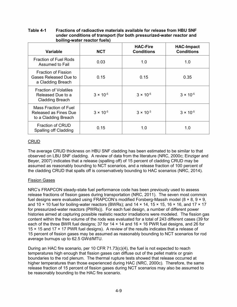
4-9
Table 4-1 Fractions of radioactive materials available for release from HBU SNF under conditions of transport (for both pressurized-water reactor and boiling-water reactor fuels)
Variable NCT HAC-Fire
Conditions HAC-Impact Conditions
Fraction of Fuel Rods Assumed to Fail 0.03 1.0 1.0
Fraction of Fission Gases Released Due to
a Cladding Breach 0.15 0.15 0.35
Fraction of Volatiles Released Due to a Cladding Breach
3 × 10⁻⁵ 3 × 10⁻⁵ 3 × 10⁻⁵
Mass Fraction of Fuel Released as Fines Due to a Cladding Breach
3 × 10⁻⁵ 3 × 10⁻³ 3 × 10⁻⁵
Fraction of CRUD Spalling off Cladding 0.15 1.0 1.0
CRUD
The average CRUD thickness on HBU SNF cladding has been estimated to be similar to that observed on LBU SNF cladding. A review of data from the literature (NRC, 2000c; Einziger and Beyer, 2007) indicates that a release (spalling off) of 15 percent of cladding CRUD may be assumed as reasonably bounding to NCT scenarios, and a release fraction of 100 percent of the cladding CRUD that spalls off is conservatively bounding to HAC scenarios (NRC, 2014).
Fission Gases
NRC’s FRAPCON steady-state fuel performance code has been previously used to assess release fractions of fission gases during transportation (NRC, 2011). The seven most common fuel designs were evaluated using FRAPCON’s modified Forsberg-Massih model (8 × 8, 9 × 9, and 10 × 10 fuel for boiling-water reactors (BWRs); and 14 × 14, 15 × 15, 16 × 16, and 17 × 17 for pressurized-water reactors (PWRs)). For each fuel design, a number of different power histories aimed at capturing possible realistic reactor irradiations were modeled. The fission gas content within the free volume of the rods was evaluated for a total of 243 different cases (39 for each of the three BWR fuel designs; 37 for 14 × 14 and 16 × 16 PWR fuel designs, and 26 for 15 × 15 and 17 × 17 PWR fuel designs). A review of the results indicates that a release of 15 percent of fission gases may be assumed as reasonably bounding to NCT scenarios for rod average burnups up to 62.5 GWd/MTU.
During an HAC fire scenario, per 10 CFR 71.73(c)(4), the fuel is not expected to reach temperatures high enough that fission gases can diffuse out of the pellet matrix or grain boundaries to the rod plenum. The thermal rupture tests showed that release occurred at higher temperatures than those experienced during HAC (NRC, 2000c). Therefore, the same release fraction of 15 percent of fission gases during NCT scenarios may also be assumed to be reasonably bounding to the HAC fire scenario.

4-10
In the case of HAC drop (impact) conditions, the pellet may be conservatively assumed to crumble. In this scenario, fission gases retained within the pellet grain boundaries may be released in addition to those already released from the fuel rod free volume (i.e., from the fuel-cladding gap and plenum). The FRAPFGR model in FRAPCON may be used to predict the location of the fission gases within the fuel pellet (NRC, 2011). The model has been validated with experimental data obtained using an electron probe microanalyzer. The FRAPFGR model was used to calculate the maximum fraction of the pellet-retained fission gases that may be released during a drop impact, which was determined to be 20 percent. Therefore, assuming all fission gases within the pellet grain boundaries are released, a 35-percent (15-percent + 20-percent) maximum release fraction may be assumed to be reasonably bounding to the HACdrop scenario. This value accounts for the 15-percent maximum fission gases released fromthe fuel rod free volume (as calculated with the modified Forsberg-Massih model) and the20-percent maximum fission gases released from the fuel pellet grain boundaries (as calculatedwith the FRAPFGR model). These release fraction estimates are consistent with previous NRCestimates (NRC, 2000c; NRC, 2007; Einziger and Beyer, 2007).
Volatiles
The majority of the volatile release fractions originate from cesium-based compounds in the form of oxides or chlorides (NRC, 2000c; NRC, 2014). These volatiles exhibit a different release behavior than that of fission gases. Volatiles tend to migrate and aggregate at the rim on the outer surface of the fuel pellet during reactor irradiation, which is characteristic of burnups near or exceeding 60 GWd/MTU. The pellet rim is characterized by a fine crystalline grain structure (0.1–0.3 µm in characteristic size) (Spino et al., 2003; Einziger and Beyer, 2007), a high porosity that may exceed 25 percent, and a high concentration of actinides relative to the inner pellet matrix.
Sandia National Laboratories determined the maximum release fraction of volatiles (cesium and other ruthenium-based compounds) under HAC drop and fire scenarios to be 0.003 percent (3×10⁻⁵) (NRC, 2000c). The assessment included modeling and analyses using various data from the literature. The volatile release fraction during an HAC fire scenario was determined to be lower than the release fraction during an HAC impact scenario (NRC, 2014; NRC, 2000c). Therefore, a volatile release fraction of 0.003 percent (3 × 10⁻⁵) may be assumed to be reasonably bounding to NCT, HAC fire, and HAC impact scenarios. This release fraction estimate is also consistent with an independent estimate by Einziger and Beyer (2007).
Fuel Fines
Release fractions from SNF fines during storage and transportation have been previously documented (NRC, 2000c; Benke et al., 2012; NRC, 2007a; NRC, 2014). HBU SNF has a different pellet microstructure than LBU SNF, which is characterized by an inner matrix and an outer pellet rim layer. The thickness of the outer pellet rim layer increases with higher fuel burnup. Therefore, differences in microstructure between the inner pellet matrix and the outer pellet rim should be considered when evaluating release fractions of fuel fines from HBU SNF.
Although there is no reported literature on HBU SNF rim fracture as a function of impact energy, other data can be used to indirectly assess the contribution of the rim layer to the release fractions of fuel fines. Spino et al. (1996) estimated the fracture toughness of the rim layer from micro-indentation tests. Relative to the inner SNF matrix, the rim layer showed an increase of fracture toughness. The increase of fracture toughness implies a decrease of release fraction. Hirose et al. (2015) also discussed the results of axial dynamic impact tests simulating accident

4-11
conditions during transport. The dispersed particles resulting from pellet breakage following impact were collected and correlated to impact energy. The staff has compared the measured release fraction of fuel fines from Hirose et al. (2015) with previous NRC estimates of release fraction versus impact energy for SNF and other brittle materials (depleted uranium dioxide, glass, and Synroc) (see Figure 3 of NUREG-1864, “A Pilot Probabilistic Risk Assessment of a Dry Cask Storage System at a Nuclear Power Plant,” issued March 2007 (NRC, 2007a). Based on these analyses, the staff concludes that there is no indication that pellet rim layer contributes to increased release fractions for HBU SNF.
Since the outer HBU fuel pellet rim does not appear to contribute to additional release fractions, previous NRC estimates for release fractions of fuel fines may continue to be used (NRC, 2000c; NRC, 2007a; Ahn et al., 2011; Benke et al., 2012; NRC, 2014). Based on the range of estimates in the literature, a release fraction for fuel fines of 0.003 percent (3 × 10⁻⁵) may be assumed to be reasonably bounding to both NCT and HAC (drop impact) scenarios. During an HAC fire scenario, fuel oxidation is conservatively assumed to increase the release fraction of fuel fines by a factor of 100 (NRC, 2000c; Ahn et al., 2011). Therefore, a 0.3-percent (3 × 10⁻³) release fraction of fuel fines may be assumed as reasonably bounding to an HAC fire scenario.
The staff recognizes that various international cooperative research programs are currently investigating release fractions from HBU SNF. Once the data are available to the public, the staff will review and determine whether the conservative estimates in the above discussion should be revisited.
4.2.3 Direct Shipment from the Spent Fuel Pool and Shipment of Previously Dry-Stored Fuel (Up to 20 Years Since Fuel Was Initially Loaded)
Section 1.2 discusses the staff’s review guidance for the licensing and certification of dry storage of HBU SNF for a period up to 20 years. The technical basis referenced in that guidance has supported the staff’s conclusion that creep is not expected to result in gross ruptures if cladding temperatures are maintained below 400 degrees C (752 degrees F). Creep is a time-dependent mechanism. Therefore, the short transportation period (compared to the duration of dry storage) is not expected to compromise the integrity of HBU SNF if the cladding temperatures remain below 400 degrees C (752 degrees F).
Chapter 2 also presents an assessment of the effects of hydride reorientation based on static and fatigue bending test results on HBU SNF specimens. Those results provide a technical basis for the staff’s conclusion that the use of best-estimate cladding mechanical properties (with either as-irradiated or hydride-reoriented microstructure) is adequate for the structural evaluation of HBU SNF. This finding applies to the evaluation of the drop tests for NCT (per 10 CFR 71.71(c)(7)) and HAC (per 10 CFR 71.73(c)(1)). Refer to the current SRP for transportation of SNF for staff review guidance on additional considerations for acceptable cladding-only mechanical properties (i.e., alloy type, burnup, temperature), on acceptable references for cladding mechanical properties, and on acceptance criteria for the structural evaluation of the HBU fuel assembly following the drop tests. As Figure 4-1 shows, supplemental safety analyses are not expected for dry storage of HBU SNF directly loaded from the spent fuel pool or HBU SNF that has previously been in dry storage for periods not exceeding 20 years.

4-12
4.2.4 Shipment of Previously Dry-Stored Fuel (Beyond 20 Years Since Fuel Was Initially Loaded)
To address age-related uncertainties related to the transportation of HBU SNF previously in dry storage for extended periods (i.e., periods of storage exceeding 20 years), the application should be supplemented with either results from a surrogate demonstration program or supplemental safety analyses assuming justified hypothetical fuel reconfiguration scenarios (see Figure 4-1). The results from a surrogate demonstration program can provide field-obtained confirmation that the fuel has remained in the analyzed configuration after 20 years of dry storage, if that is the approved configuration for the transportation package. If confirmation is not provided, the safety analyses for the transportation package should be revised to assume reconfigured fuel.
The licensing and certification of storage containers for HBU SNF has been approved for an initial 20-year term per the technical basis for the evaluation of creep, as discussed in Chapter 1. However, the staff has recognized that the technical basis is based on short-term accelerated creep testing (i.e., laboratory-scale testing of up to a few months), which results in increased uncertainties when extrapolated to long periods of dry storage (see Appendix D to NUREG-1927, Revision 1, “Standard Review Plan for Renewal of Specific Licenses and Certificates of Compliance for Dry Storage of Spent Nuclear Fuel,” issued June 2016 (NRC, 2016b). Although the staff has confidence based on this short-term testing that creep-related degradation of the HBU fuel will not adversely affect its analyzed configuration for storage periods beyond 20 years, there is no operational field-obtained data to confirm this expectation, as in the prior demonstration for LBU fuel (NRC, 2001; NRC, 2003b).
In addition, the staff acknowledges that, while the CIRFT results obtained to date (as discussed in Chapter 2) provide an adequate technical basis for assessing the separate effects of hydride reorientation, the results do not account for potential synergistic effects of various physical and chemical phenomena occurring during extended dry storage (e.g., cladding creep, hydride reorientation, irradiation hardening, oxidation, hydriding caused by residual water hydrolysis (see NUREG-2214, “Managing Aging Processes in Storage (MAPS) Report,” issued July 2019 (NRC, 2019), for discussions of these phenomena). Therefore, evidence that HBU fuel in dry storage beyond 20 years has maintained its analyzed configuration is expected before transport, if that is the approved configuration for the transportation package.
4.2.4.1 Supplemental Data from Confirmatory Demonstration
One example of an approach for approval of a transportation package with HBU SNF previously in dry storage for periods exceeding 20 years (e.g., 40 years) involves supplementing the application with results from a surrogate demonstration program. Such a program could provide field-obtained confirmation that the fuel configuration has been maintained before transport. The applicant may refer to Appendices B and D to NUREG-1927, Revision 1 (NRC, 2016b), which describe attributes and acceptance criteria of an acceptable surrogate demonstration program.
4.2.4.2 Supplemental Safety Analyses
As an alternative approach to relying on a surveillance and monitoring program for the transportation of HBU SNF previously in dry storage for longer than 20 years, an application may demonstrate that a transportation package can still meet the pertinent regulatory requirements by assuming hypothetical reconfiguration of the fuel contents into justified

4-13
geometric forms. This alternative approach would include supplemental safety analyses to demonstrate that the HBU SNF contents, even if reconfigured, can still meet the pertinent 10 CFR Part 71 regulations for containment, thermal performance, criticality safety, and shielding after the required tests for NCT and HAC.
In NUREG/CR-7203 (NRC, 2015), Oak Ridge National Laboratory (ORNL) evaluated the impact of a wide range of postulated fuel reconfiguration scenarios under nonmechanistic causes of fuel assembly geometry change with respect to criticality, shielding (dose rates), containment, and thermal performance. The study considered three fuel reconfiguration categories, which were characterized by either (1) cladding failure, (2) rod/assembly deformation without cladding failure, or (3) changes to assembly axial alignment without cladding failure. Within configurations in both Category 1 and Category 2, various scenarios were identified:
• Category 1: cladding failure
– Scenario 1(a): breached spent fuel rods– Scenario 1(b): damaged spent fuel rods
• Category 2: rod/assembly deformation without cladding failure
– Scenario 2(a): configurations associated with side drop– Scenario 2(b): configurations associated with end drop
• Category 3: changes to assembly axial alignment without cladding failure
The analyses in NUREG/CR-7203 (NRC, 2015) considered representative SNF transportation packages and a range of fuel initial enrichments, discharge burnup values, and decay times. The analyses examined two package designs: a general burnup credit (GBC)-32 package containing 32 PWR fuel assemblies and a GBC-68 package containing 68 BWR fuel assemblies. The results in NUREG/CR-7203 should not be assumed to be generically applicable, as fuel reconfiguration may have different consequences for a transportation package other than the generic models evaluated in NUREG/CR-7203; however, the following sections discuss considerations in developing supplemental safety analyses for other packages according to the reconfiguration scenarios considered in NUREG/CR-7203.
4.2.4.2.1 Materials and Structural
An application for package certification relying on supplemental safety analyses based on hypothetical reconfiguration of the HBU SNF contents should still provide a structural evaluation for the package and its fuel contents using any of the approaches discussed in Section 4.2. The staff will follow the guidance in the current SRP for transportation of SNF in its review of the structural evaluation and the assumed material mechanical properties, including any changes caused by higher temperatures resulting from fuel reconfiguration.
4.2.4.2.2 Containment
An application relying on supplemental safety analyses based on hypothetical reconfiguration of the HBU SNF is expected to demonstrate that the transportation package design meets the regulatory requirements for containment if data from a surrogate demonstration program, used

4-14
for confirmatory demonstration consistent with the guidance in NUREG-1927, Revision 1 (NRC, 2016b), are not available before shipment of fuel in prior dry storage for periods longer than 20 years.
Thermal, structural, and material analyses, together with aging management activities for the dry storage system subcomponents supporting confinement (i.e., confinement boundary) during prior dry storage,9F
1 serve to assure that the allowable leak rate is maintained even after hypothetical reconfiguration of the fuel under NCT and HAC. Supplemental thermal analyses should demonstrate that the containment boundary will be able to withstand the maximum operating temperatures and pressures under NCT and HAC. If the canister serves as the confinement boundary at the future storage location, then the canister is expected to be leak-tested while it is within the transportation package after it reaches its new storage location.
4.2.4.2.3 Thermal
Fuel reconfiguration can affect the efficiency of heat removal from the fuel because of changes in (1) thermo-physical properties of the container gas space resulting from the release of fuel rod fill gas and fission product gases, (2) heat source location within the container, and (3) changes in flow area (convection), conduction lengths (conduction), and radiation viewfactors (thermal radiation). As part of a defense-in-depth approach to addressing age-relateduncertainties for uncanned or undamaged HBU SNF in shipment for fuel previously in drystorage for longer than 20 years, the thermal analyses would be expected to analyze the spentfuel at NCT and HAC by assuming the fuel has become substantially altered. NUREG/CR-7203(NRC, 2015) describes impacts on canister pressure and fuel cladding, and packagecomponent temperatures for various scenarios of fuel geometry changes. These impacts areexamined below. In general, the results in NUREG/CR-7203 should not be consideredgenerically applicable. The thermal analyses of the application should consider scenariosdiscussed in NUREG/CR-7203 to determine consistency in the analytical methods, scenariophenomena, and results. The thermal analyses would be expected to assess the impact of fuelreconfiguration on the fuel cladding and component temperatures and the internal pressure forthe particular transportation package design.
For Scenario 1(a) of Category 1 (see the list of scenarios in Section 4.2.4.2 of this report) from NUREG/CR-7203, the fuel rods are assumed to breach in such a manner that the cladding remains in its nominal geometry (no fuel reconfiguration), but the release of fuel rod backfill gas and fission product gases can cause a change to the package component peak temperatures. For Scenario 1(b) of Category 1, for configurations where an assembly (or assemblies) is represented as a debris pile(s) inside its basket cell, fuel reconfiguration has a larger impact on the component temperatures for the vertical orientation than for the horizontal orientation, but the packing fraction of debris bed has minor impact on the component temperatures. For both Scenarios 1(a) and 1(b), release of the fuel rod gaseous contents increases the number of moles of gas and thus the package container pressure. The canister pressure is expected to increase with the increased fuel rod failure fractions.
For Category 2 (Scenarios 2(a) and 2(b)), the fuel rods are assumed to remain intact without gaseous leakage into the canister space. The changes of the fuel assembly lattice (contraction in Scenario 2(a) and expansion in Scenario 2(b)) could cause either an increase or decrease in
1 Aging management activities may be conducted under the aegis of an NRC-approved aging management program (for renewal applications) or a maintenance plan (for initial license or CoC applications requesting approval for periods exceeding 20 years).

4-15
the package component temperatures depending on the initial assembly geometry and whether the package relies on convection for heat transfer. In general, the impact from Scenarios 2(a) and 2(b) is expected to be minor for the package component temperatures and canister pressure.
For Category 3, the fuel rods are assumed to remain intact without gaseous leakage into the canister space, but the axial shifting of the assembly changes the heat source location within the packaging. It is expected that changes in assembly axial alignment within the basket cells have minor impact on the component temperatures and canister pressure.
Normal Conditions of Transport
Based on the thermal phenomena described in Section 4.2.4.2.3 and NUREG/CR-7203 (NRC, 2015), an application should evaluate the impact of Scenarios 1(a) and 1(b) of Category 1 on the canister pressure and the fuel cladding and package component temperatures for 3-percent fuel rod failure for NCT thermal evaluation.
For Scenarios 2(a) and 2(b) in Category 2 and Scenario 3 in Category 3, although the impact of hypothetical fuel reconfiguration on package thermal performance (e.g., temperature and pressure) is not expected to be significant because the fuel rods are assumed to remain intact without gaseous leakage into the canister space, the applicant may need to provide thermal analyses based on the specifics of the package design.
Hypothetical Accident Conditions
Based on thermal phenomena described in Section 4.2.4.2.3 and NUREG/CR-7203 (NRC, 2015), an application should evaluate the impact of Scenarios 1(a) and 1(b) of Category 1 on the canister pressure and the fuel cladding and package component temperatures for 100-percent fuel rod failure for HAC thermal evaluation.
For Scenarios 2(a) and 2(b) in Category 2 and Scenario 3 in Category 3, although the impact of fuel reconfiguration on package thermal performance (e.g., temperature and pressure) is not expected to be significant because the fuel rods are assumed to remain intact without gaseous leakage into the canister space, the applicant may need to provide thermal analyses based on specifics of the package design.
4.2.4.2.4 Criticality
An application may demonstrate that a transportation package meets the regulatory requirements for criticality safety by assuming hypothetical reconfiguration of the HBU SNF into justified bounding geometric forms. If data from a surrogate demonstration program are not available before the shipment of fuel previously dry-stored for longer than 20 years, this approach is one way to provide additional assurance of compliance with 10 CFR 71.55, “General Requirements for Fissile Material Packages,” and 10 CFR 71.59, “Standards for Arrays of Fissile Material Packages,” during NCT and HAC.
To assess the impacts of hypothetical fuel reconfiguration, ORNL performed criticality safety analyses for various scenarios and examined the impacts on the reactivity of a package. The results were described in NUREG/CR-7203 (NRC, 2015) which considers burnup up to
4-16
70 GWd/MTU for criticality evaluations. The study characterized the assumed hypothetical reconfiguration scenarios based on the nature of the assembly damage, as described previously.
With respect to criticality safety analyses, NUREG/CR-7203 (NRC, 2015) provides some insight into the reactivity effects of some reconfiguration scenarios; however, the values in the results are not generically applicable. Fuel reconfiguration may have different reactivity effects on a transportation package other than the generic models used in NUREG/CR-7203.
Criticality is not a concern for dry SNF transportation packages, as SNF requires moderation to reach criticality. The criticality analyses in NUREG/CR-7203 (NRC, 2015) assume fully flooded conditions, and any conclusions adopted apply only to analyses that include moderator intrusion. The staff will follow the guidance in ISG-19, “Moderator Exclusion under Hypothetical Accident Conditions and Demonstrating Subcriticality of Spent Fuel under the Requirements of 10 CFR 71.55(e),” issued May 2003 (NRC, 2003), to review an application for moderator exclusion. The following considerations for criticality evaluations for reconfigured fuel apply only to transportation packages that do not employ moderator exclusion.
All of the criticality safety analyses presented in NUREG/CR-7203 (NRC, 2015) take credit for burned fuel nuclides (burnup credit), and the results may not apply to analyses that assume a fresh fuel composition. To review the burnup credit methodology and code benchmarking used to support a criticality safety evaluation, the staff will follow the guidance in ISG-8, Revision 3, “Burnup Credit in the Criticality Safety Analyses of PWR Spent Fuel in Transportation and Storage Casks,” issued September 2012 (NRC, 2012). ISG-8, Revision 3, does not endorse any particular methodology for BWR fuel burnup. The staff does not necessarily endorse the methodology used to perform the study presented in NUREG/CR-7203 for dry storage systems for BWR fuel and considers it to be for illustration only.
For criticality safety analyses using burnup credit, NUREG/CR-7203 (NRC, 2015) shows that reactivity increases for longer decay times. Therefore, analyses supporting storage beyond 20 years would need to use an appropriate decay time in the criticality evaluations. The enrichment and burnup values assumed in the criticality evaluations in NUREG/CR-7203 may differ from the values allowed in another transportation package. However, NUREG/CR-7203 states that no significant differences were observed in trends between configurations that evaluated fuel at 44.25 GWd/MTU and 70 GWd/MTU.
The following sections discuss an approach acceptable to the staff for addressing increases in reactivity resulting from the potential reconfiguration for HBU fuel under NCT and HAC. These sections identify the most applicable information from NUREG/CR-7203 to address each of these specific conditions.
Normal Conditions of Transport
In an approach acceptable to the staff, the applicant’s criticality safety evaluations would consider the reactivity impact of 3-percent fuel failure under NCT. Based on NUREG/CR-7203 (NRC, 2015), the impacts on the package keff resulting from 3-percent fuel failure may become significant. Applicants for transportation packages may need to consider the 3-percent fuel failure for both single package and array analyses under NCT.
The scenario most applicable to 3-percent fuel failure under NCT is Category 1, Scenario 1(a), from NUREG/CR-7203. ORNL created this scenario to represent breached rods. ORNL

4-17
assumed that a percentage of the rods were breached and that cladding from these rods failed completely. ORNL then removed this percentage of fuel rods from the system. This is conservative as SNF is under-moderated, and replacing fuel with moderator typically causes reactivity to increase. Using a fresh fuel composition for PWR fuel, NUREG/CR-7203 shows that reactivity decreases when removing rods; therefore, this type of analysis may not be appropriate for PWR analyses that assume a fresh fuel composition. The location assumed for failed or removed rods can have a significant effect on reactivity. Section A.1.1 of NUREG/CR-7203 shows that removing rods from the center of the assembly causes reactivity to increase the most.
In NUREG/CR-7203 (NRC, 2015), ORNL also determined the number of rods removed that produces the maximum reactivity. For the systems studied in NUREG/CR-7203, the maximum reactivity occurs when more than 3 percent of the rods are removed from the system.
NUREG/CR-7203 (NRC, 2015) also presents the results of a sensitivity study that shows increased reactivity for an alternative Category 1, Scenario 1(a), which assumed that the failed fuel relocates to a location outside of the absorber plate. This is based on the generic system modeled in NUREG/CR-7203. A different package may allow relocation of the failed rod material outside of the absorber plate material to a different extent, and an applicant would evaluate an alternative scenario for the specific transportation package being assessed.
Hypothetical Accident Conditions
In an approach acceptable to the staff, the applicant’s criticality safety evaluations would consider the reactivity impact of 100-percent fuel failure under HAC. Based on NUREG/CR-7203 (NRC, 2015), the impacts on the package keff resulting from 100-percent fuel failure may be significant. Applicants for transportation packages may need to consider the 100-percent fuel failure for both single package and array analyses under HAC.
The applicable scenarios from NUREG/CR-7203 (NRC, 2015) for the hypothetical case of 100-percent fuel failure are a combination of Category 1, Scenario 1(b); Category 2 scenarios;and Category 3 scenarios.
In Scenario 1(b) in Section A.1.2 of NUREG/CR-7203 (NRC, 2015), ORNL considered reconfiguration of damaged fuel. With 100-percent compromise in cladding integrity, reconfiguration is considered to the maximum extent. Section A.1.2 of NUREG/CR-7203 shows that a model assuming an “ordered pellet array” is more reactive than a homogeneous mixture of fuel, cladding materials, and water.
In Scenario 2 in Section A.2 of NUREG/CR-7203 (NRC, 2015), ORNL considered rod/assembly deformation from side and end impact events. ORNL investigated the effects on birdcaging and bottlenecking by changing the pitch uniformly and nonuniformly. For all pitch contraction cases, ORNL calculated a decrease in keff from the nominal pitch. For the uniform pitch expansion, ORNL found that the maximum pitch increase possible within the basket cell resulted in the highest keff. For the nonuniform pitch expansion, ORNL increased the pitch of the inner fuel rods/pins by decreasing the space between the outer rods/pins. The results in NUREG/CR-7203 show that nonuniform pitch expansion produces keff values higher than uniform pitch expansion for all cases except the unchanneled BWR fuel.
In Scenario 3 in Section A.3 of NUREG/CR-7203 (NRC, 2015), ORNL considered reactivity effects of changes in assembly axial alignment. Neutron absorber panels may not extend the

4-18
full length of the basket, and it may be possible for fuel to reconfigure outside of the neutron absorber panels. ORNL investigated the change in reactivity resulting from the displacement of intact fuel assemblies outside of the neutron absorber panels. NUREG/CR-7203 shows that the maximum reactivity increase results when displacing the assemblies to the maximum extent at the top, versus the bottom, because there is less burnup at the top of the assembly. The amount of displacement possible depends on the particular transportation package and may differ from that of the package(s) analyzed in NUREG/CR-7203. Higher burnup assemblies show the largest change in keff upon displacement; however, the increase in keff caused by the displacement may be bounded by the keff from a nondisplaced lower burned assembly.
4.2.4.2.5 Shielding
An application may demonstrate that a transportation package meets the regulatory requirements for shielding safety by showing that, with reconfiguration of the HBU SNF, the package meets the dose rate limits under NCT and HAC. If a confirmatory demonstration is not applicable or available, this approach is one way to provide additional assurance of compliance with 10 CFR 71.47, “External Radiation Standards for All Packages”; 10 CFR 71.51(a)(1) for NCT; and 10 CFR 71.51(a)(2) for HAC.
To assess the impacts of various fuel geometry changes on the calculated external dose rates of an SNF transportation package, ORNL evaluated the external dose rate for various scenarios of fuel geometry changes and showed the results in NUREG/CR-7203 (NRC, 2015) for example BWR and PWR transportation packages.
The results in NUREG/CR-7203 (NRC, 2015) should not be considered generically applicable for external dose rate analyses. The impacts of fuel reconfiguration on the maximum external dose rates may be different based on the package design.
Since reconfiguration is to be considered for transportation packages shipped after 20 years of storage, and this length of cooling time is generally much longer than cooling times used to establish loading tables, applicants may be able to justify that increases to external dose resulting from reconfiguration are bounded by the additional cooling time the assemblies will experience. As discussed in Section B.5 of NUREG/CR-7203 (NRC, 2015), based on decay time, different nuclides become important in the evaluations.
NUREG/CR-7203 (NRC, 2015) also indicates that fuel assembly type (i.e., PWR versus BWR) may have a significant impact on the external dose rate under fuel reconfiguration scenarios. Tables 9 through 12 of NUREG/CR-7203 show the difference in dose rate increase for BWR and PWR SNF. In addition, a transportation package may allow transport of other fuel assemblies, with different allowable burnup and enrichments. The burnup profile and depletion parameters used to create the source term within NUREG/CR-7203 may also not be generically applicable. Appendix B to NUREG/CR-7203 presents details of the analyses.
The following sections discuss an approach acceptable to the staff for addressing increases in external dose rate resulting from the potential reconfiguration of HBU fuel under NCT and HAC. These sections identify the most applicable information from NUREG/CR-7203 (NRC, 2015) to address each of these specific conditions.

4-19
Normal Conditions of Transport
In an approach acceptable to the staff, the applicant’s external dose rate evaluations would evaluate the impact of 3-percent fuel failure under NCT. Based on NUREG/CR-7203 (NRC, 2015), source relocation resulting from 3-percent fuel failure may have a significant impact on the dose rates prescribed in 10 CFR 71.47(b). The most applicable scenario from NUREG/CR-7203 is Category 1 (fuel failure), Scenario 1(a). The results show that the dose rate changes are sensitive to the number of fuel rod breaches and available space for fuel to move in the cavity.
For breached rods in Category 1, Scenario 1(a), ORNL assumed that when the cladding is breached, the rods turn to rubble and calculated the dose rate when the rubbleized fuel mixture relocated within the fuel assembly. ORNL assumed failure of 10 and 25 percent of PWR fuel rods and 11 percent of BWR fuel rods. Section B.4.1 of NUREG/CR-7203 (NRC, 2015) discusses this configuration scenario in detail. ORNL reduced the source strength and density of the active fuel zone by the failure percentage, relocated this source to a different part of the fuel assembly, and increased the source strength and density accordingly. ORNL then calculated external dose rates using models with the fuel rubble mixture relocated to varied locations of the package (top, middle, bottom). The limiting location for the relocated fuel rubble would be based on the characteristics of the transportation package being analyzed.
Hypothetical Accident Conditions
In an approach acceptable to the staff, the applicant’s external dose rate evaluations would consider the impact of 100-percent fuel failure under HAC. The applicable scenarios from NUREG/CR-7203 (NRC, 2015) are the Category 1 scenarios, Category 2 scenarios, and Category 3 scenarios. ORNL assumed that there was no neutron shield present for the HAC models. This is a typical assumption in HAC dose rate evaluations as it is difficult to predict the condition of the neutron shield after the HAC fire event. Therefore, source terms with high neutron radiation, such as HBU fuel, tend to be limiting for HAC.
NUREG/CR-7203 (NRC, 2015) shows that source relocation resulting from 100-percent fuel failure can significantly impact external dose rates under HAC. Tables 11 and 12 of NUREG/CR-7203 show the relative changes for the example packages under HAC. These dose rate change ratios are for dose rates at 1 meter from the package, as required by 10 CFR 71.51(a)(2).
For Category 1 scenarios (cladding failure), ORNL assumed in the analyses in NUREG/CR-7203 (NRC, 2015) that when the cladding fails, the rods turn to rubble and then created a model with homogenized fuel and basket material. ORNL determined that the limiting mass packing fraction for rubbleized fuel and basket material is 0.58. When evaluating dose rates for a package in the vertical orientation, the damaged fuel model from Category 1, Scenario 1(b), in NUREG/CR-7203 is applicable. For a package in a horizontal orientation, the Category 2 scenario from NUREG/CR-7203 would be more applicable. In this scenario, ORNL analyzed the dose rates when the fuel is kept within its respective basket cell but pushed to the side walls as shown in Section B.4.2 of NUREG/CR-7203. The limiting scenarios for any given transportation package would depend on the specific characteristics of that package.
In the Category 3 scenario in NUREG/CR-7203 (NRC, 2015), ORNL evaluated the dose rate increase when an intact fuel assembly is pushed to the bottom or top of the package, thus increasing dose rates at the bottom or top, or radially if the source becomes aligned with an

4-20
area of the package where there is streaming. The results from NUREG/CR-7203 generally show a smaller increase in dose rates for this scenario than for the Category 1 and Category 2 scenarios and are likely to be bounded by the results for those situations. However, a particular package may have specific features that make this scenario worth considering.
4.3 Canned Fuel
HBU SNF that has been classified as damaged should be placed in a can designed for damaged fuel or in an acceptable alternative. The staff will follow the guidance in the current SRP for transportation of SNF when reviewing an application for a transportation package with damaged HBU SNF contents.

5-1
5 CONCLUSIONS
The information in this report provides technical background information on the mechanical performance of high burnup (HBU) spent nuclear fuel (SNF) after drying operations for storage and transportation. The report also provides an engineering assessment of the test results for HBU SNF discussed in NUREG/CR-7198, Revision 1, “Mechanical Fatigue Testing of High-Burnup Fuel for Transportation Applications,” issued October 2017 (NRC, 2017), and proposes example approaches for licensing and certification of HBU SNF for dry storage (under Title 10 of the Code of Federal Regulations (10 CFR) Part 72, “Licensing Requirements for the Independent Storage of Spent Nuclear Fuel, High-Level Radioactive Waste, and Reactor-Related Greater Than Class C Waste”) and transportation (under 10 CFR Part 71, “Packaging and Transportation of Radioactive Material”) based on the engineering assessment.
Until recently, experimental testing on the structural behavior of SNF rods during transportation and storage has focused primarily on obtaining mechanical properties that consider only the material strength of the cladding. Historically, the fuel pellet’s contribution to the flexural rigidity and structural response of the fuel rod during normal and accident conditions has been ignored because of the lack of experimental bending test data. Recent research sponsored by the U.S. Nuclear Regulatory Commission (NRC) on the static bending response and fatigue strength of HBU SNF rods (i.e., rods with burnup exceeding 45 GWd/MTU), with the presence of the fuel pellets, has provided some of the data necessary to more accurately assess the structural behavior of the composite HBU SNF rod system (NRC, 2017). The staff has examined the results from this research to assess the expected behavior of HBU SNF under normal conditions of transport (NCT) and hypothetical accident conditions (HAC), as well as dry storage system drop and tipover accident scenarios.
The results in NUREG/CR-7198, Revision 1 (NRC, 2017), for static bend testing of aggressively hydride-reoriented Zircaloy-4 HBU SNF rods support the staff’s conclusion that the use of best estimate cladding mechanical properties that do not account for the presence of the fuel pellet continues to be adequate for assessing the structural performance of HBU SNF rods during a hypothetical 9-m (30-ft) drop accident, as required in 10 CFR 71.73(c)(1). The same conclusion applies to the lower loads experienced during a 0.3-m (1-ft) drop, per the requirement in 10 CFR 71.71(c)(7), and postulated drop and cask tipover accident scenarios during dry storage operations, per the requirement in 10 CFR 72.122(b). Further, the staff concludes that the orientation of the hydrides is not a critical consideration when evaluating the adequacy of cladding-only mechanical properties. Therefore, the use of mechanical properties for cladding in either the as-irradiated or hydride-reoriented condition is considered acceptable for the evaluation of drop and cask tipover accident scenarios. If an applicant is unable to demonstrate satisfactory performance of the HBU SNF rod by assuming cladding-only mechanical properties, the staff has proposed an alternative approach for using the results from static bend testing to account for the increased flexural rigidity imparted by the fuel pellet.
After considering the aggressive hydride reorientation treatment used for the Zircaloy-4 HBU SNF rods, the staff concludes that the same response is expected for all modern commercial cladding alloy types that may experience hydride reorientation (i.e., Zircaloy-2, ZIRLO™, and M5). The staff has also reviewed proprietary and nonproprietary data on end-of-life rod internal pressures for fuel rods with boron-based integral fuel burnable absorbers (see Section 1.5.3) and considers these rods to be reasonably bound by the maximum rod internal pressure used in the radial hydride treatment of the Zircaloy-4 HBU SNF rods. The staff expects that additional static bend testing and fatigue testing of HBU SNF composite rods with other claddings will

5-2
confirm this conclusion. The U.S. Department of Energy is currently planning to conduct these tests, which the NRC will evaluate when available (Hanson et al., 2016).
In addition, the results in NUREG/CR-7198, Revision 1 (NRC, 2017), on the fatigue testing of aggressively hydride-reoriented Zircaloy-4 HBU SNF rods have provided an adequate technical basis for establishing a reasonable lower-bound fatigue curve and endurance limit for tensile axial-bending loads experienced during transport. Therefore, the staff concludes that applicants can use a cumulative damage approach and the curve mentioned above in support of their structural evaluation to assess vibration normally incident to transport of Zircaloy-4 HBU SNF, as required by 10 CFR 71.71(c)(5). Fatigue test data for other cladding alloy types would be needed to develop their respective lower-bound fatigue curves and endurance limits. The U.S. Department of Energy is currently planning to conduct additional fatigue strength testing of HBU SNF composite rods with other claddings, which will provide the necessary data to develop those curves and define the respective endurance limits (Hanson et al., 2016).
This report also presents examples of licensing and certification approaches for HBU SNF to address age-related uncertainties associated with conclusions based on accelerated separate-effects testing. One of these approaches, the use of a surveillance and monitoring program for confirmation of design-basis HBU SNF configuration, is consistent with the guidance in NUREG-1927, Revision 1, “Standard Review Plan for Renewal of Specific Licenses and Certificates of Compliance for Dry Storage of Spent Nuclear Fuel,” issued June 2016 (NRC, 2016b). Alternatively, the staff has proposed an example approach based on demonstrating compliance with the pertinent regulatory requirements even if hypothetical reconfiguration of the design-basis fuel were to occur. This example approach considers lessons learned from an NRC-sponsored generic consequence assessment for transportation packages, as discussed in NUREG/CR-7203, “A Quantitative Impact Assessment of Hypothetical Spent Fuel Reconfiguration in Spent Fuel Storage Casks and Transportation Packages,” issued September 2015 (NRC, 2015).

6-1
6 REFERENCES
Adamson, R., F. Garzarolli, B. Cox, A. Strasser, and P. Rudling. 2007. “Corrosion Mechanisms in Zirconium Alloys,” IZNA7 Special Topic Report, Advanced Nuclear Technology International, Skultuna, Sweden.
Ahn, T., R. Sun, T. Wilt, S. Kamas, and S. Whaley. 2011. “Source Term Analysis in Handling Canister-Based Spent Nuclear Fuel: Preliminary Dose Estimate,” U.S. Nuclear Regulatory Commission, Washington, DC. Agencywide Documents Access and Management System (ADAMS) Accession No. ML112640440.
American National Standards Institute, ANSI N14.5-2014, “American National Standard for Radioactive Materials—Leakage Tests on Packages for Shipment,” New York, NY.
American National Standards Institute/American Nuclear Society (ANSI/ANS) 57.9, “Design Criteria for an Independent Spent Fuel Storage Installation (Dry Storage Type
Aomi, M., T. Baba, T. Miyashita, K. Kaminura, T. Yasuda, Y. Shinohara, and T. Takeda. 2008. “Evaluation of Hydride Reorientation and Mechanical Properties for High-Burnup Fuel-Cladding Tubes in Interim Dry Storage,” Journal of ASTM International, JAl101262.
Bai, J., J. Gilbon, C. Prioul, and D. Francois. 1994. “Hydride Embrittlement in Zircaloy-4 Plate, Part I, Influence of Microstructure on the Hydride Embrittlement in Zircaloy-4 at 20°C and 350°C” and Part II, “Interaction Between the Tensile Stress and the Hydride Morphology,” Metallurgical and Materials Transactions A, Vol. 25A, Issue 6, pp. 1,185–1,197, June 1994.
Benke, R., H. Jung, A. Ghosh, Y.-M. Pan, and J. Tait. 2012. “Potential Releases inside a Spent Nuclear Fuel Dry Storage Cask Due to Impacts: Relevant Information and Data Needs,” CNWRA-2012-001, Center for Nuclear Waste Regulatory Analyses, San Antonio, TX, August 2012. ADAMS Accession No. ML12226A177.
Biggs, J.M. 1964. Introduction to Structural Dynamics, McGraw-Hill, New York, NY.
Billone, M.C, T.A. Burtseva, and Y. Yan. 2012. “Ductile-to-Brittle Transition Temperature for High-Burnup Zircaloy-4 and ZIRLO™ Cladding Alloys Exposed to Simulated Drying-Storage Conditions,” September 28, 2012. ADAMS Accession No. ML12181A238.
Billone, M.C., T.A. Burtseva, Z. Han, and Y.Y. Liu. 2013. “Embrittlement and DBTT of High-Burnup PWR Fuel Cladding Alloys,” DOE Used Fuel Disposition Campaign Report FCRD-UFD-2013-000401, ANL Report ANL-13/16.
Billone, M.C., T.A. Burtseva, Z. Han, and Y.Y. Liu. 2014. “Effects of Multiple Drying Cycles on High-Burnup PWR Cladding Alloys, DOE Used Fuel Disposition Report,” FCRD-UFD-2014-000052, ANL Report ANL-144/11.
Billone, M.C., T.A. Burtseva, and M.A. Martin-Rengel. 2015. “Effects of Lower Drying-Storage Temperatures on the DBTT of High-Burnup PWR Cladding Alloys,” DOE Used Fuel Disposition Report FCRD-UFD-2015-000008, ANL Report ANL-15/21.
Bouffioux, P., A. Ambard, A. Miquet, C. Cappelaere, Q. Auxzoux, M. Bono, O. Rabouille, S. Allegre, V. Chabretou, and C.P. Scott. 2013. “Hydride Reorientation in M5® Cladding and its
6-2
Impact on Mechanical Properties,” Paper 1155, Proceedings LWR Fuel Performance Meeting (TopFuel2013), Charlotte, NC, September 15–19, 2013.
Bratton, R.N., M.A. Jessee, and W.A. Wieselquist. 2015. “Rod Internal Pressure Quantification and Distribution Analysis Using FRAPCON,” DOE Report FCRD-UFD-2015-000636, ORNL Report ORNL/TM-2015/557, September 30, 2015.
Cazalis, B., C. Bernaudat, P. Yvon, J. Desquines, C. Poussard, and X. Averty. 2005. “The PROMETRA program: a reliable material database for highly irradiated Zircaloy-4, ZIRLO™ and M5™ fuel claddings,” Paper SMiRT18-C02-1, Proceedings of the 18th International Conference on Structural Mechanics in Reactor Technology, 18th ed., August 2005.
Chung, H.M. 2004. “Understanding Hydride- and Hydrogen-Related Processes in High-Burnup Cladding in Spent-Fuel-Storage and Accident Situations,” Paper 1064, Proceedings of the 2004 International Meeting on LWR Fuel Performance, Orlando, FL, September 19–22, 2004.
Colas, K., A. Motta, M.R. Daymond, and J. Almer. 2014. “Mechanisms of Hydride Reorientation in Zircaloy-4 Studied in Situ,” STP 1543, Proceedings of the ASTM 17th International Symposium on Zirconium in the Nuclear Industry, pp. 1107–1137.
Einziger, R. and C. Beyer. 2007. “Characteristics and Behavior of High-Burnup Fuel that Affect the Source Terms for Cask Accidents,” Nuclear Technology, 159:134–146.
Fourgeaud, S., J. Desquines, M. Petit, C. Getrey, and G. Sert. 2009. “Mechanical characteristics of fuel-rod cladding in transport conditions,” Packaging, Transport, Storage & Security of Radioactive Material, 20:69-76.
Gaylord, Jr., E.H. and C.H. Gaylord, 1979. Structural Engineering Handbook, 2nd Edition, McGraw-Hill, New York, NY.
Geelhood, K.J., W.J. Luscher, and C.E. Beyer. 2008. “PNNL Stress/Strain Correlation for Zircaloy,” PNNL-17700, Pacific Northwest National Laboratory, Richland, WA, July 2008.
Geelhood, K.J., W.J. Luscher, and P.A. Raynaud. 2014. “Material Property Correlations: Comparisons Between FRAPCON-3.5, FRAPTRAN-1.5, and MATPRO,” NUREG/CR-7024, Rev. 1, October 2014. ADAMS Accession No. ML14296A063.
Gruss, K.A, C.L. Brown, and M.W. Hodges. 2004. “USNRC Acceptance Criteria and Cladding Considerations for the Dry Storage and Transportation of SNF,” Proceedings PATRAM 2004 Meeting, Berlin, Germany, September 20–24, 2004.
Hanson, B., H. Alsaed, C. Stockman, D. Enos, R. Meyer, and K. Sorenson. 2012. “Used Fuel Disposition Campaign: Gap Analysis To Support Extended Storage of Used Nuclear Fuel,” Rev. 0, Pacific Northwest National Laboratory, Richland, WA.
Hanson, B.D., S.C. Marschman, M.C.Billone, J. Scaglione, K.B. Sorenson, and S.J. Saltzstein. 2016. “High Burnup Spent Fuel Data Project. Sister Rod Test Plan Overview,” FCRD-UFD-2016-000063, PNNL-25374, Pacific Northwest National Laboratory, Richland, WA.
Hashin, Z., and A. Totem 1976. “A Cumulative Damage Theory of Fatigue Failure “, Air Force Office of Scientific Research, AFOSR 76-3014.

6-3
Hirose, T., M. Ozawa, and A. Yamauchi. 2015. “Fuel Rod Mechanical Behavior under Dynamic Load Condition on High Burnup Spent Fuel of BWR and PWR,” International Conference on Management of Spent Fuel from Nuclear Power Reactors: An Integrated Approach to the Back-End of the Fuel Cycle, Vienna, Austria, June 15–19, 2015.
International Atomic Energy Agency (IAEA). 2011. “Impact of High Burnup Uranium Oxide and Mixed Uranium-Plutonium Oxide Water Reactor Fuel on Spent Fuel Management,” IAEA Nuclear Energy Series NF-T-3.8, Vienna, Austria.
Ito, K., K. Kamimura, and Y. Tsukada. 2004. “Evaluation of Irradiation Effect on Fuel, Cladding Creep Properties,” Proceedings 2004 International Meeting on LWR Fuel Performance, Orlando, FL, September 19–22, 2004.
Jung, H., P. Shukla, T. Ahn, L. Tipton, K. Das, X. He, and D. Basu. 2013. “Extended Storage and Transportation: Evaluation of Drying Adequacy.” ADAMS Accession No. ML13169A039.
Kammenzind, B.F., D.G. Franklin, H.R. Peters, and W.J. Duffin. 1996. “Hydrogen Pickup and Redistribution in Alpha-Annealed Zircaloy-4,” Zirconium in the Nuclear Industry: 11th International Symposium, ASTM STP 1295, E.R. Bradley and G.P. Sabol, Eds., ASTM, pp. 338–370.
Kearns, J.J. 1967. “Terminal Solubility and Partitioning of Hydrogen in the Alpha Phase of Zirconium, Zircaloy-2 and Zircaloy-4,” Journal of Nuclear Materials, 22:292–303.
Machiels, A. 2005. “Spent Fuel Transportation Applications: Fuel Rod Failure Evaluation under Simulated Cask Side Drop Conditions,” Electric Power Research Institute Report 1009929, Washington, DC.
Machiels, A. 2013. “End-of-Life Rod Internal Presures in Spent Pressurized Water Reactor Fuel,” Electric Power Research Institute Report 3002001949, Washington, DC.
McEachern, R.J. and P. Taylor. 1998. “A review of the oxidation of uranium dioxide at temperatures below 400°C,” Journal of Nuclear Materials, 254:87–121.
McMinn, A., E.C. Darby, and J.S. Schofield. 2000. “The Terminal Solid Solubility of Hydrogen in Zirconium Alloys,” Zirconium in the Nuclear Industry: 12th International Symposium, ASTM STP 1354, G.P. Sabol and G.D. Moan, Eds., ASTM, pp. 173–195.
NRC. 2000. “Reexamination of Spent Fuel Shipment Risk Estimates,” Vol. 1, NUREG/CR-6672, SAND2000-0234, Washington, DC, March 2000. ADAMS Accession No. ML003698324.
NRC. 2001. “Dry Cask Storage Characterization Project—Phase 1; CASTOR V/21 Cask Opening and Examination,” NUREG/CR-6745, Washington, DC, September 2001. ADAMS Accession No. ML013020363.
NRC. 2003a. “Cladding Considerations for the Transportation and Storage of Spent Fuel,” Interim Staff Guidance 11, Rev. 3, Washington, DC, November 2003. ADAMS Accession No. ML033230335.

6-4
NRC. 2003b. “Examination of Spent PWR Fuel Rods after 15 Years in Dry Storage,” NUREG/CR-6831, Washington, DC, September 2003. ADAMS Accession No. ML032731021.
NRC. 2003c. “Moderator Exclusion under Hypothetical Accident Conditions and Demonstrating Subcriticality of Spent Fuel under the Requirements of 10 CFR 71.55(e),” Interim Staff Guidance 19, Washington, DC, May 2003. ADAMS Accession No. ML031250639.
NRC. 2006. “Potential Rod Splitting Due to Exposure to an Oxidizing Atmosphere During Short-Term Cask Loading Operations in LWR or Other Uranium Oxide Based Fuel,” Interim Staff Guidance 22, Washington, DC, May 2006. ADAMS Accession No. ML061170217.
NRC. 2007a. “A Pilot Probabilistic Risk Assessment of a Dry Cask Storage System at a Nuclear Power Plant,” NUREG-1864, Washington, DC, March 2007. ADAMS Accession No. ML071340012.
NRC. 2007b. “Classifying the Condition of Spent Nuclear Fuel for Interim Storage and Transportation Based on Function,” Interim Staff Guidance 1, Rev. 2, Washington, DC, May 2007. ADAMS Accession No. ML071420268.
NRC. 2011. “FRAPCON-3.4: A Computer Code for the Calculation of Steady-State Thermal-Mechanical Behavior of Oxide Fuel Rods for High Burnup,” NUREG/CR-7022, Vol. 1, Washington, DC, March 2011. ADAMS Accession No. ML11101A005.
NRC. 2012. “Burnup Credit in the Criticality Safety Analyses of PWR Spent Fuel in Transportation and Storage Casks,” Interim Staff Guidance 8, Rev. 3, Washington, DC, September 2012. ADAMS Accession No. ML12261A433.
NRC. 2014. “Spent Fuel Transportation Risk Assessment—Final Report,” NUREG-2125, Washington, DC, January 2014. ADAMS Accession No. ML14031A323.
NRC. 2015. “A Quantitative Impact Assessment of Hypothetical Spent Fuel Reconfiguration in Spent Fuel Storage Casks and Transportation Packages,” NUREG/CR-7203, Washington, DC, September 2015. ADAMS Accession No. ML15266A413.
NRC. 2016a. “Fuel Retrievability in Spent Fuel Storage Applications,” Interim Staff Guidance 2, Rev. 2, Washington, DC, April 2016. ADAMS Accession No. ML16117A080.
NRC. 2016b. “Standard Review Plan for Renewal of Specific Licenses and Certificates of Compliance for Dry Storage of Spent Nuclear Fuel,” NUREG-1927, Rev. 1, Washington, DC, June 2016. ADAMS Accession No. ML16179A148.
NRC. 2017. “Mechanical Fatigue Testing of High-Burnup Fuel for Transportation Applications,” NUREG/CR-7198, Rev. 1, Washington, DC, October 2017. ADAMS Accession No. ML17292B057.
NRC. 2019. “Managing Aging Processes in Storage (MAPS) Report,” NUREG-2214, Washington, DC, July 2019. ADAMS Accession No. ML19214A111.
NRC. 2020a. “Standard Review Plan for Spent Fuel Dry Storage Systems and Facilities – Final Report,” NUREG-2215, Washington, DC, February 2020. ADAMS Accession No. ML20121A190.

6-5
NRC. 2020b. “Standard Review Plan for Transportation Packages for Spent Fuel and Radioactive Material: Final Report,” NUREG-2216, Washington, DC, August 2020. ADAMS Accession No. ML20234A651.
Pan, G., A.M. Garde, and A.R. Atwood. 2013. “Performance and Property Evaluation of High-Burn-up Optimized ZIRLO™ Cladding,” Proceedings of the 17th ASTM Symposium on Zirconium in the Nuclear Industry, Hyderabad, India, February 3–7, 2013.
Patterson, C. and F. Garzarolli. 2015. “Dry Storage Handbook: Fuel Performance in Dry Storage,” A.N.T. International, Mölnlycke, Sweden.
Pickard, A. 2015. “Fatigue Crack Propagation in Biaxial Stress Fields,” Journal of Strain Analysis for Engineering Design, 50(1):25–39.
Richmond, D.J. and K.J. Geelhood. 2018. “FRAPCON Analysis of Cladding Performance during Dry Storage Operations,” PNNL-27418, Pacific Northwest National Laboratory, Richland, WA, April 2018.
Roark, R. and W. Young. 1975. Formulas for Stress and Strain, 5th Edition, McGraw-Hill, New York, NY.
Sanders, T., K. Seager, Y. Rashid, P. Barrett, A. Malinauskas, R. Einziger, H. Jordan, T. Duffey, S. Sutherland, and P. Reardon. 1992. “A Method for Determining the Spent Fuel Contribution to Transport Cask Containment Requirements,” SAND90-2406, Sandia National Laboratories, Albuquerque, NM.
Spino, J., M. Coquerelle, and D. Baron. 1996. “Microstructure and Fracture Toughness Characterization of Irradiated PWR Fuels in the Burnup Range of 40–67 GWd/MTU,” Proceedings of the Technical Committee Meeting IAEA on Advances in Fuel Technology, Vienna, Austria.
Spino, J., J. Cobos-Sabate, and F. Rousseau. 2003. “Room-Temperature Microindentation Behavior of LWR-fuels, Part 1: Fuel Microhardness,” Journal of Nuclear Material, 322:204–216.
Tang, D., A. Rigato, and R.E. Einziger. 2015. “Flaw Effects and Flaw Reorientation on Spent Fuel Rod Performance, a Simulation with Finite Element Analysis,” Proceedings of the ASME 2015 Pressure Vessels and Piping Conference, July 19–23, 2015, Boston, MA.
U.S. Code of Federal Regulations, “Standards for Protection Against Radiation” Part 20, Chapter I, Title 10, “Energy.” 2019. U.S. Code of Federal Regulations, “Domestic Licensing of Production and Utilization Facilities,” Part 50, Chapter I, Title 10, “Energy.” 2019. U.S. Code of Federal Regulations, “Licenses, Certifications, and Approvals for Nuclear Power Plants,” Part 52, Chapter I, Title 10, “Energy.” 2019. U.S. Code of Federal Regulations, “Packaging and Transportation of Radioactive Material,” Part 71, Chapter I, Title 10, “Energy.” 2019.
6-6
U.S. Code of Federal Regulations, “Licensing Requirements for the Independent Storage of Spent Nuclear Fuel, High-Level Radioactive Waste, and Reactor-Related Greater Than Class C Waste,” Part 72, Chapter I, Title 10, “Energy.” Wang, J.-A., H. Wang, H. Jiang, Y. Yan, B.B. Bevard, and J.M. Scaglione. 2016. “FY 2016 Status Report: Documentation of All CIRFT Data Including Hydride Reorientation Tests,” Oak Ridge National Laboratory, ORNL/SR-2016/424, September 14, 2016, Oak Ridge, TN.
Winter, G. and A. Nelson. 1979. Design of Concrete Structures, 9th Edition, McGraw-Hill, New York, NY.
Wisner, S. and R. Adamson. 1998. “Combined Effects of Radiation Damage and Hydrides on the Ductility of Zircaloy-2,” Nuclear Engineering and Design, Vol. 185, pp. 33–49.

February 2016Type Title and Subtile here
Please list Authors here.
Please type Organization and address here.
Street
Division of
Office of
Please type supplementary here.
Please type or cut and paste Abstract information here. Please note that this section can’t be over 200 words.
Key words/descriptors
Select & delete if n/a
Technical
dates
Please leave blank
November 2020 Dry Storage and Transportation of High Burnup Spent Fuel
Final Report
T. Ahn, H. Akhavannik, G. Bjorkman, F.C. Chang, W. Reed, A. Rigato,D. Tang, R.D. Torres, B.H. White, V. Wilson
Division of Spent Fuel Management Office of Nuclear Material Safety and Safeguards U.S. Nuclear Regulatory Commission Washington, DC 20555-0001
Same as above
.
The potential for changes in the cladding performance of high burnup (HBU) spent nuclear fuel (SNF) to compromise the analyzed fuel configuration in dry storage systems and transportation packages has been historically addressed through safety review guidance. The guidance defines adequate fuel conditions, including peak cladding temperatures during short-term loading operations to prevent or mitigate degradation of the cladding. The purpose of this report is to expand the technical basis in support of that guidance, as it pertains to the mechanism of hydride reorientation in HBU SNF cladding.
This report also provides an engineering assessment of the results of NRC-sponsored research on the mechanical performance of HBU SNF following hydride reorientation and, per the conclusions of that assessment, provides example approaches for licensing and certification of HBU SNF for dry storage (under 10 CFR Part 72) and transportation (under 10 CFR Part 71).
High Burnup Spent Fuel Dry Storage Systems Transportation Packages Hydride Reorientation
NUREG-2224
Technical


NU
REG
-2224 Final
Dry Storage and Transportation of High B
urnup Spent Fuel Novem
ber 2020


