Compressed air is an essential power source that is widely used throughout industry. This safe, powerful and reliable utility can be the most important part of your production process. However, your compressed air will contain water, dirt, wear particles and even degraded lubricating oil which all mix together to form an unwanted condensate. This condensate often acidic, rapidly wears tools and pneumatic machinery, blocks valves and orifices causing high maintenance and costly air leaks. It also corrodes piping systems and can bring your production process to an extremely expensive standstill!
The quality of air required throughout a typical compressed air system can vary.
It is highly recommended that the compressed air is treated prior to entry into the distribution system as well as at each usage point or application.
This approach to system design provides the most
cost effective solution to system purification as it not only removes the contamination already in the distribution system, it ensures that only the most critical areas receive air treated to the highest level.
In many instances the compressed air system will be supplying air to more than one application and although the purification equipment specified in the compressor room would remain unchanged, the point of use protection will vary depending upon the air quality requirements of each application.
In many cases this action alone is not enough, as modern production systems and processes demand an even higher level of air quality. Where required, “point of use” filtration, refrigeration or desiccant air dryers can provide the correct air quality, without the need for drying the complete compressed air installation, which can be both costly and totally unnecessary.
Sources of contamination found in a compressed air system
Compressed air and its purification from generation to application
Sources of Contamination
Contaminants in a compressed air system can generally be attributed to the following:
The quality of air being drawn into the compressor Air compressors draw in a large volume of air from the surrounding atmosphere containing large numbers of airborne contaminants.
The type and operation of the air compressor The air compressor itself can also add contamination, from wear particles to coolants and lubricants.
Compressed air storage devices and distribution systems The air receiver and system piping are designed to store and distribute the compressed air. As a consequence, they will also store the large amounts of contaminants drawn into the system. Additionally, piping and air receivers will also cool the moist compressed air forming condensate which causes damage and corrosion.
Types of contamination found in a compressed air system
Atmospheric DirtAtmospheric air in an industrial environment typically contains 183 million per yd3 (140 million per m3) of dirt particles. 80% of these particles are less than 2 microns in size and are too small to be captured by the compressor intake filter, therefore passing directly into the compressed air system.
Water Vapor, Condensed Water And Water AerosolsAtmospheric air contains water vapor (water in a gaseous form). The ability of compressed air to hold water vapor is dependent upon it's temperature. The higher the temperature, the more water vapor that can be held by the air. During compression, the air temperature is increased significantly, which allows it to easily retain the incoming moisture. After the compression stage, air is normally cooled to a usable temperature. This reduces the airs ability to retain water vapor, resulting in a proportion of the water vapor being condensed into liquid water which is removed by a condensate drain fitted to the compressor after-cooler. The air leaving the after-cooler is now 100% saturated with water vapor and any further cooling of the air will result in more water vapor condensing into liquid water. Condensation occurs at various stages throughout the system as the air is cooled further by the air receiver, piping and the expansion of valves, cylinders, tools and machinery. The condensed water and water aerosols cause corrosion to the storage and distribution system, damage production equipment and the end product. It also reduces production efficiency and increases maintenance costs. Water in any form must be removed to enable the system to run correctly and efficiently.
Rust and PipescaleRust and pipescale can be found in air receivers and the piping of “wet systems” (systems without adequate purification equipment) or systems which were operated “wet” prior to purification being installed. Over time, this contamination breaks away to cause damage or blockage in production which can also contaminate final product and processes.
Micro-OrganismsBacteria and viruses will also be drawn into the compressed air system through the compressor intake and warm, moist air provides an ideal environment for the growth of micro-organisms. If only a few micro-organisms were to enter a clean environment, a sterile process or production system, enormous damage could be caused that not only diminishes product quality, but may even render a product entirely unfit for use and subject to recall.
Liquid Oil And Oil AerosolsMost air compressors use oil in the compression stage for sealing, lubrication and cooling. During operation, lubricating oil is carried over into the compressed air system as liquid oil and aerosols. This oil mixes with water vapor in the air and is often very acidic, causing damage to the compressed air storage and distribution system, production equipment and final product.
Oil VaporIn addition to dirt and water vapor, atmospheric air also contains oil in the form of unburned hydrocarbons. The unburned hydrocarbons drawn into the compressor intake as well as vaporized oil from the compression stage of a lubricated compressor will carry over into a compressed air system where it can cool and condense, causing the same contamination issues as liquid oil.
Up to 99% of the total liquid contamination found in a compressed air system is water.
Sources of Contamination
The amount of water in a compressed air system is staggering. A small 100 SCFM (2.8m3/min) compressor and refrigeration dryer combination, operating for 4,000 hours in typical climatic conditions can produce approximately 2,200 gallons (8,328 liters) of liquid condensate per year.
If the compressor is oil lubricated with a typical 2ppm (2 mg/m3) oil carryover, then although the resulting condensate would visually resemble oil, oil would in fact account for less than 0.1% of the
overall volume and it is this resemblance to oil to which a false association is made.
The example above assumes uses a small compressor to highlight the large volume of condensate produced. If a compressed air system was operated in warmer, more humid climates, or with larger compressors installed, running for longer periods, the volume of condensate would increase significantly.
Oil is perceived to cause the most problems as it is seen emanating from open drain points and exhausting valves, however, in the majority of
How much water can be found in a typical compressed air system?
Having identified the different types of contamination that can be found within a
compressed air system, we can now examine the purification technologies available for it's removal.
instances, it is actually oily condensate (oil mixed with water) that is being observed.
It is often believed that the level of compressed air purification equipment required in a system is dependent upon the type of compressor used. Contamination in a compressed air system originates from many sources and is not related solely to the compressor or it's lubricants. No
Contamination and types of compressors
Compressed air and it’s purification
matter what compressor type is selected, adequate filtration and separation products will be required to remove the large volume of dirty contaminated water as well as the dirt, rust, pipescale and microbiological contamination in the system.
Preventative maintenance provides you with the following benefits:
• Continued protection of downstream equipment and processes
Bulk liquid removal high efficiency water separators
Particle and coalescing filtersCoalescing filters are probably the most important items of purification equipment in any compressed air system. They are designed to remove oil and water aerosols using mechanical filtration techniques and have the additional benefit of removing solid particulate to very low levels (as small as 0.01micron in size). Installed in pairs, most users believe one to be an oil removal filter and the
other to be a particulate filter, when in fact, the pair of filters both perform the same function. The first filter, a general purpose filter is used to protect the high efficiency filter against bulk contamination. This "dual filter" installation ensures a continuous supply of high quality compressed air with low operational costs and minimal maintenance time.
Used to protect filters in systems where excessive cooling takes place in distribution piping. Water Separators will remove in excess of 98% of bulk
liquid contamination through centrifugal separation techniques.
Refrigeration dryers work by cooling the air, so are limited to positive pressure dewpoint ratings to prevent freezing of the condensed liquid. Ideal for general purpose applications, they typically provide pressure dewpoints of 38°F (3°C), 45°F (7°C) or 50°F (10°C) pdp. Air is reheated before it re-enters
the system to prevent piping from “sweating” in humid conditions. Refrigeration dryers are not suitable for installations where piping is installed in ambient temperatures below the dryer dewpoint i.e. systems with external piping.
Water vapor is water in a gaseous form and is removed from compressed air using a dryer, with dryer performance being measured as pressure dewpoint. Adsorption or desiccant dryers remove moisture by passing air over a regenerative adsorbent material which strips the moisture from the air. This type of dryer is extremely efficient and typical pressure dewpoint ratings are -40°F (-40°C) or -100°F (-70°C) pdp. This means that for water
vapor to condense into a liquid, the air temperature would have to drop below -40°F (-40°C) to -100°F (-70°C) respectively (the actual air temperature after an adsorption dryer is not the same as it's dewpoint).
Beneficially, a pressure dewpoint of -15°F (-26°C) or better will not only prevent corrosion, but will also inhibit the growth of microorganisms within the compressed air system.
As adsorption and refrigeration dryers are designed to remove only water vapor and not water in a liquid form, they require the use of particulate
and coalescing filters, and possibly a bulk liquid separator to work efficiently.
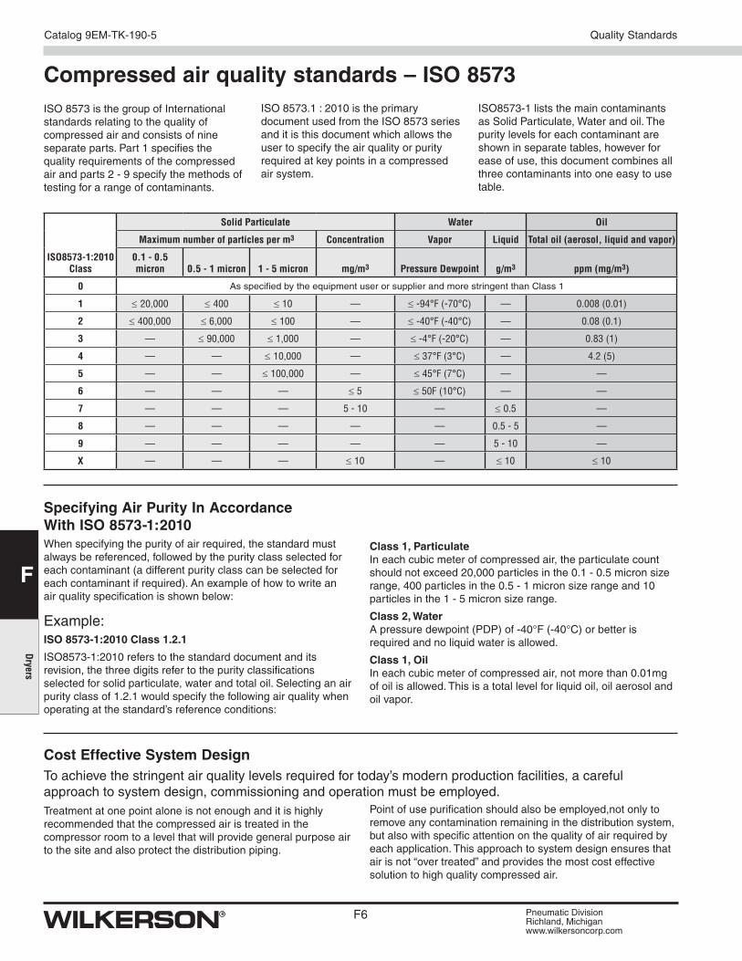
ISO 8573.1 : 2010 is the primary document used from the ISO 8573 series and it is this document which allows the user to specify the air quality or purity required at key points in a compressed air system.
Compressed air quality standards – ISO 8573ISO 8573 is the group of International standards relating to the quality of compressed air and consists of nine separate parts. Part 1 specifies the quality requirements of the compressed air and parts 2 - 9 specify the methods of testing for a range of contaminants.
ISO8573-1:2010 Class
Solid Particulate Water Oil
Maximum number of particles per m3 Concentration Vapor Liquid Total oil (aerosol, liquid and vapor)
ISO8573-1 lists the main contaminants as Solid Particulate, Water and oil. The purity levels for each contaminant are shown in separate tables, however for ease of use, this document combines all three contaminants into one easy to use table.
Treatment at one point alone is not enough and it is highly recommended that the compressed air is treated in the compressor room to a level that will provide general purpose air to the site and also protect the distribution piping.
Point of use purification should also be employed,not only to remove any contamination remaining in the distribution system, but also with specific attention on the quality of air required by each application. This approach to system design ensures that air is not “over treated” and provides the most cost effective solution to high quality compressed air.
Specifying Air Purity In Accordance With ISO 8573-1:2010When specifying the purity of air required, the standard must always be referenced, followed by the purity class selected for each contaminant (a different purity class can be selected for each contaminant if required). An example of how to write an air quality specification is shown below:
Example:ISO 8573-1:2010 Class 1.2.1
ISO8573-1:2010 refers to the standard document and its revision, the three digits refer to the purity classifications selected for solid particulate, water and total oil. Selecting an air purity class of 1.2.1 would specify the following air quality when operating at the standard’s reference conditions:
Class 1, Particulate In each cubic meter of compressed air, the particulate count should not exceed 20,000 particles in the 0.1 - 0.5 micron size range, 400 particles in the 0.5 - 1 micron size range and 10 particles in the 1 - 5 micron size range.
Class 2, Water A pressure dewpoint (PDP) of -40°F (-40°C) or better is required and no liquid water is allowed.
Class 1, Oil In each cubic meter of compressed air, not more than 0.01mg of oil is allowed. This is a total level for liquid oil, oil aerosol and oil vapor.
Cost Effective System DesignTo achieve the stringent air quality levels required for today’s modern production facilities, a careful approach to system design, commissioning and operation must be employed.
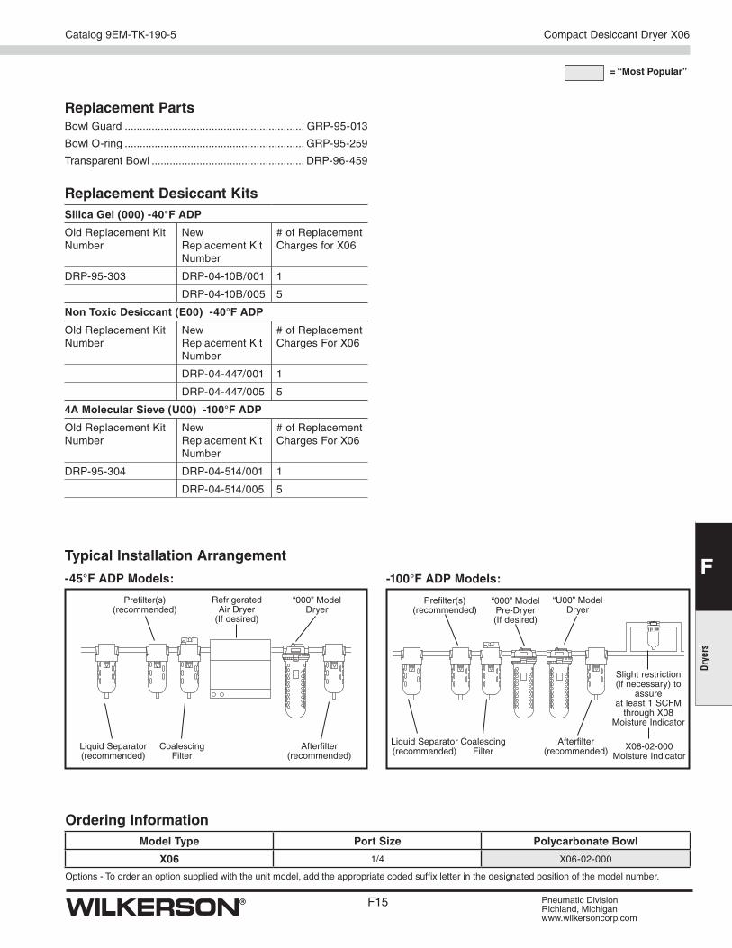
Bulk contamination is removed to an adequate level prior to the air entering the distribution system.Point of use particulate filter(s) are used for removal of contamination within the distribution system.Point of use adsorption dryer installed where lower dewpoints are required.
Bulk contamination is removed to an adequate level prior to the air entering the distribution system.Point of use particulate filter(s) are used for removal of contamination within the distribution system.Adsorbtion dryers are used for critical applications where lower dewpoints are required.
Typical Applications• Plant Automation
• Air Logistics
• Pneumatic Tools
• General Instrumentation
Typical Applications• Blow Molding of Plastics e.g.. P.E.T.
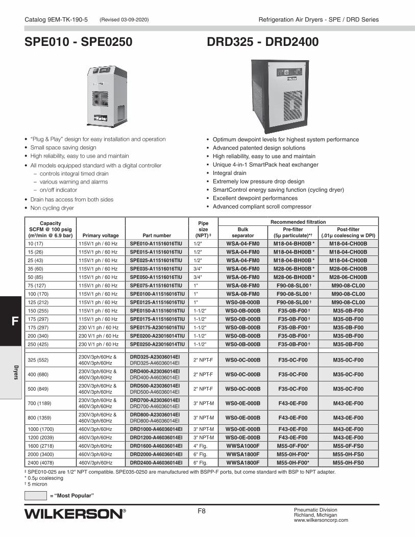
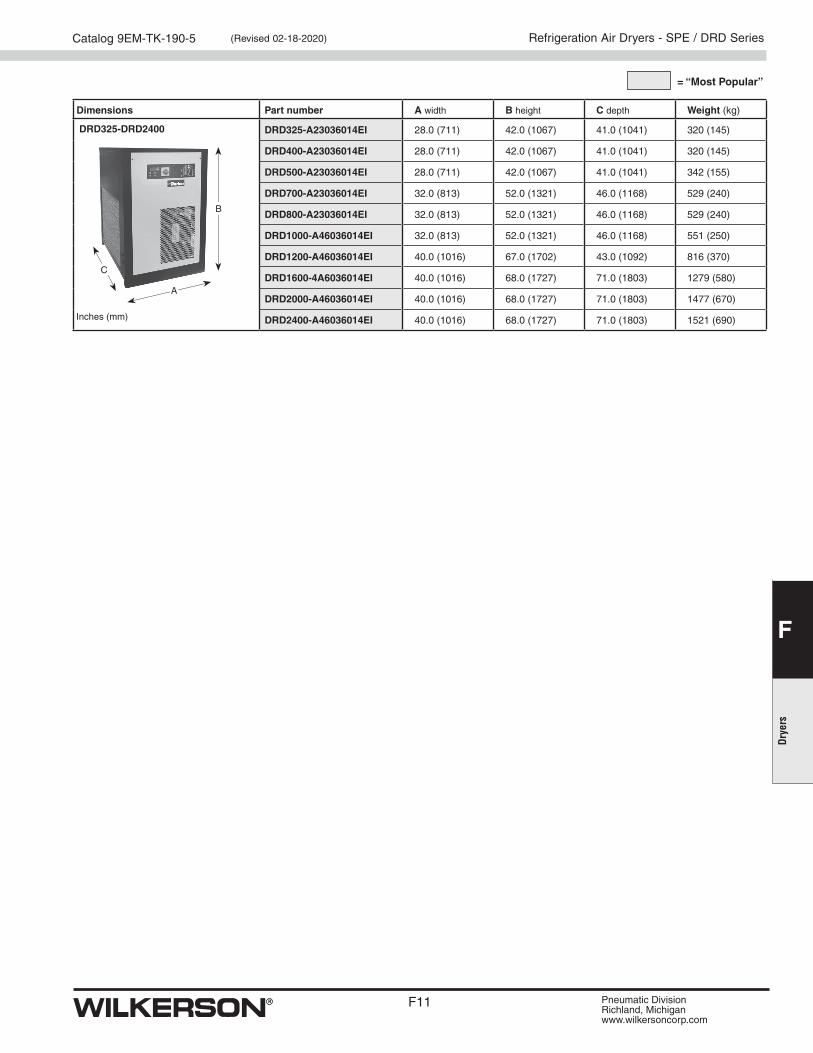
2400 (4078) 460V/3ph/60Hz DRD2400-A46036014EI 6" Flg. WWSA1800F M55-0H-F00* M55-0H-FS0‡ SPE010-025 are 1/2" NPT compatible. SPE035-0250 are manufactured with BSPP-F ports, but come standard with BSP to NPT adapter.* 0.5µ coalescing† 5 micron
• “Plug & Play” design for easy installation and operation• Small space saving design• High reliability, easy to use and maintain
• All models equipped standard with a digital controller – controls integral timed drain – various warning and alarms – on/off indicator
• Drain has access from both sides• Non cycling dryer
• Optimum dewpoint levels for highest system performance
• Advanced patented design solutions
• High reliability, easy to use and maintain
• Unique 4-in-1 SmartPack heat exchanger
• Integral drain
• Extremely low pressure drop design
• SmartControl energy saving function (cycling dryer)
• Excellent dewpoint performances
• Advanced compliant scroll compressor
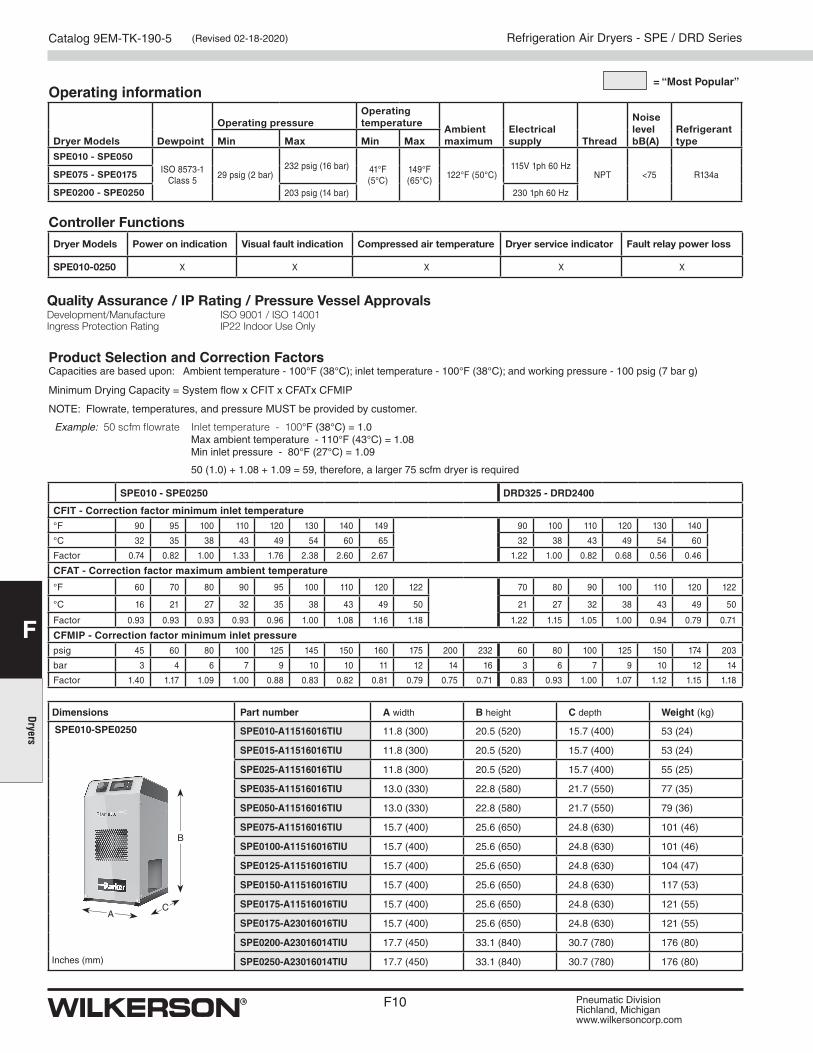
SPE010 - SPE0250 DRD325 - DRD2400
= “Most Popular”
Refrigeration Air Dryers - SPE / DRD Series (Revised 03-09-2020)
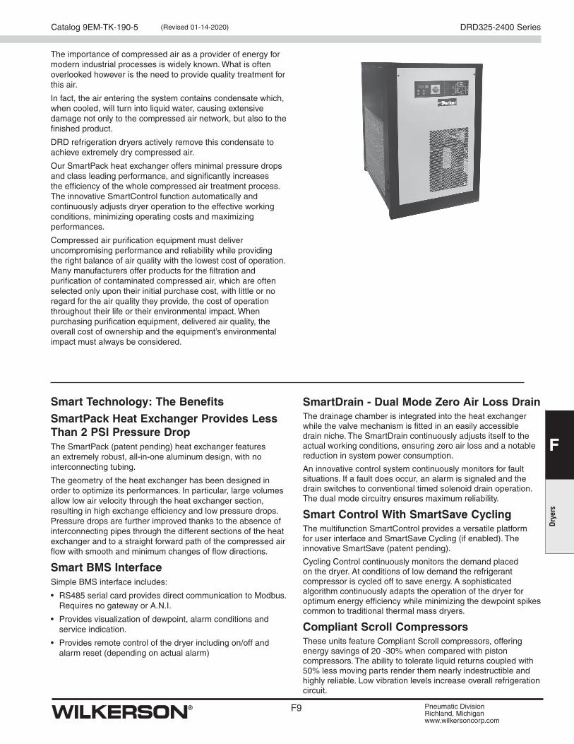
The importance of compressed air as a provider of energy for modern industrial processes is widely known. What is often overlooked however is the need to provide quality treatment for this air.
In fact, the air entering the system contains condensate which, when cooled, will turn into liquid water, causing extensive damage not only to the compressed air network, but also to the finished product.
DRD refrigeration dryers actively remove this condensate to achieve extremely dry compressed air.
Our SmartPack heat exchanger offers minimal pressure drops and class leading performance, and significantly increases the efficiency of the whole compressed air treatment process. The innovative SmartControl function automatically and continuously adjusts dryer operation to the effective working conditions, minimizing operating costs and maximizing performances.
Compressed air purification equipment must deliver uncompromising performance and reliability while providing the right balance of air quality with the lowest cost of operation. Many manufacturers offer products for the filtration and purification of contaminated compressed air, which are often selected only upon their initial purchase cost, with little or no regard for the air quality they provide, the cost of operation throughout their life or their environmental impact. When purchasing purification equipment, delivered air quality, the overall cost of ownership and the equipment’s environmental impact must always be considered.
Smart Technology: The Benefits
SmartPack Heat Exchanger Provides Less Than 2 PSI Pressure DropThe SmartPack (patent pending) heat exchanger features an extremely robust, all-in-one aluminum design, with no interconnecting tubing.
The geometry of the heat exchanger has been designed in order to optimize its performances. In particular, large volumes allow low air velocity through the heat exchanger section, resulting in high exchange efficiency and low pressure drops. Pressure drops are further improved thanks to the absence of interconnecting pipes through the different sections of the heat exchanger and to a straight forward path of the compressed air flow with smooth and minimum changes of flow directions.
Smart BMS InterfaceSimple BMS interface includes:
• RS485 serial card provides direct communication to Modbus. Requires no gateway or A.N.I.
• Provides visualization of dewpoint, alarm conditions and service indication.
• Provides remote control of the dryer including on/off and alarm reset (depending on actual alarm)
SmartDrain - Dual Mode Zero Air Loss DrainThe drainage chamber is integrated into the heat exchanger while the valve mechanism is fitted in an easily accessible drain niche. The SmartDrain continuously adjusts itself to the actual working conditions, ensuring zero air loss and a notable reduction in system power consumption.
An innovative control system continuously monitors for fault situations. If a fault does occur, an alarm is signaled and the drain switches to conventional timed solenoid drain operation. The dual mode circuitry ensures maximum reliability.
Smart Control With SmartSave CyclingThe multifunction SmartControl provides a versatile platform for user interface and SmartSave Cycling (if enabled). The innovative SmartSave (patent pending).
Cycling Control continuously monitors the demand placed on the dryer. At conditions of low demand the refrigerant compressor is cycled off to save energy. A sophisticated algorithm continuously adapts the operation of the dryer for optimum energy efficiency while minimizing the dewpoint spikes common to traditional thermal mass dryers.
Compliant Scroll CompressorsThese units feature Compliant Scroll compressors, offering energy savings of 20 -30% when compared with piston compressors. The ability to tolerate liquid returns coupled with 50% less moving parts render them nearly indestructible and highly reliable. Low vibration levels increase overall refrigeration circuit.
Product Selection and Correction Factors Capacities are based upon: Ambient temperature - 100°F (38°C); inlet temperature - 100°F (38°C); and working pressure - 100 psig (7 bar g)
Minimum Drying Capacity = System flow x CFIT x CFATx CFMIP
NOTE: Flowrate, temperatures, and pressure MUST be provided by customer.
Example: 50 scfm flowrate Inlet temperature - 100°F (38°C) = 1.0 Max ambient temperature - 110°F (43°C) = 1.08 Min inlet pressure - 80°F (27°C) = 1.09
50 (1.0) + 1.08 + 1.09 = 59, therefore, a larger 75 scfm dryer is required
SPE010 - SPE0250 DRD325 - DRD2400
CFIT - Correction factor minimum inlet temperature
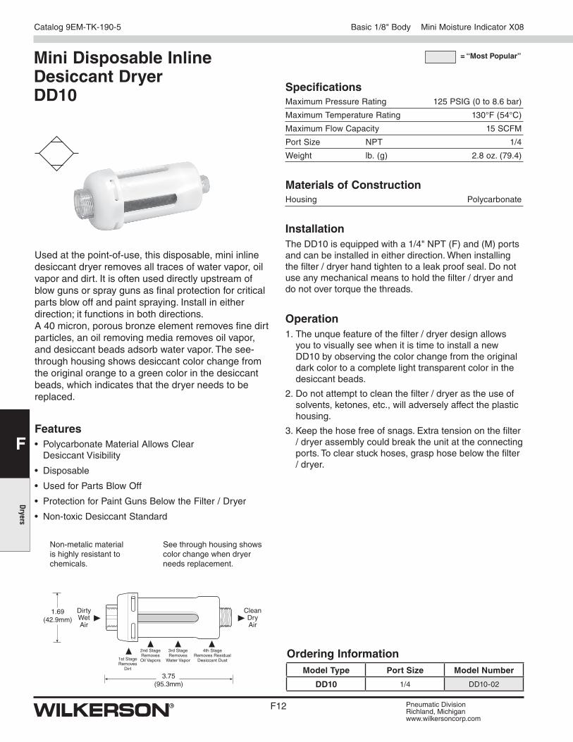
Used at the point-of-use, this disposable, mini inline desiccant dryer removes all traces of water vapor, oil vapor and dirt. It is often used directly upstream of blow guns or spray guns as final protection for critical parts blow off and paint spraying. Install in either direction; it functions in both directions. A 40 micron, porous bronze element removes fine dirt particles, an oil removing media removes oil vapor, and desiccant beads adsorb water vapor. The see-through housing shows desiccant color change from the original orange to a green color in the desiccant beads, which indicates that the dryer needs to be replaced.
Features• Polycarbonate Material Allows Clear
Desiccant Visibility
• Disposable
• Used for Parts Blow Off
• Protection for Paint Guns Below the Filter / Dryer
• Non-toxic Desiccant Standard
3.75(95.3mm)
1.69(42.9mm)
CleanDryAir
DirtyWetAir
See through housing shows color change when dryer needs replacement.
Non-metalic material is highly resistant to chemicals.
2nd StageRemovesOil Vapors
3rd StageRemoves
Water Vapor
4th StageRemoves Residual
Desiccant Dust1st StageRemoves
Dirt
Mini Disposable Inline Desiccant Dryer DD10
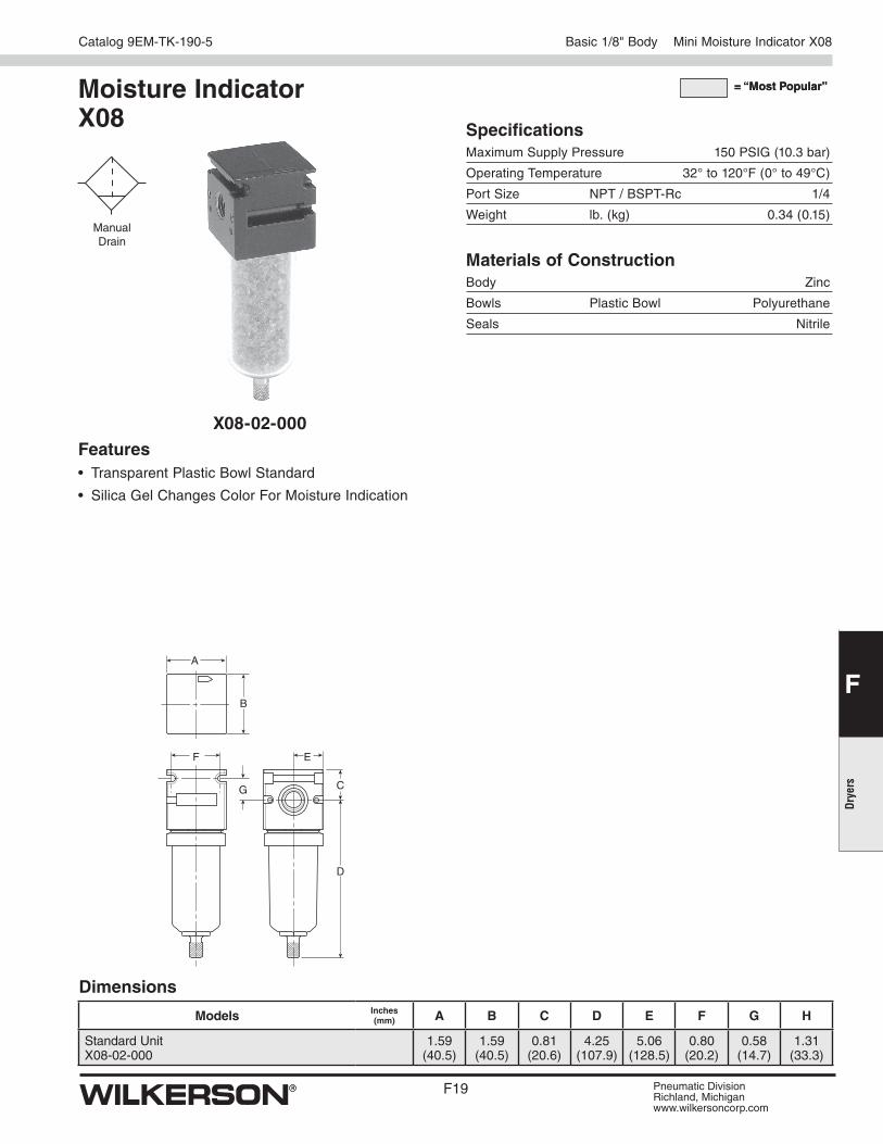
Basic 1/8" Body Mini Moisture Indicator X08
SpecificationsMaximum Pressure Rating 125 PSIG (0 to 8.6 bar)
Maximum Temperature Rating 130°F (54°C)
Maximum Flow Capacity 15 SCFM
Port Size NPT 1/4
Weight lb. (g) 2.8 oz. (79.4)
Materials of ConstructionHousing Polycarbonate
Ordering InformationModel Type Port Size Model Number
DD10 1/4 DD10-02
InstallationThe DD10 is equipped with a 1/4" NPT (F) and (M) ports and can be installed in either direction. When installing the filter / dryer hand tighten to a leak proof seal. Do not use any mechanical means to hold the filter / dryer and do not over torque the threads.
Operation1. The unque feature of the filter / dryer design allows
you to visually see when it is time to install a new DD10 by observing the color change from the original dark color to a complete light transparent color in the desiccant beads.
2. Do not attempt to clean the filter / dryer as the use of solvents, ketones, etc., will adversely affect the plastic housing.
3. Keep the hose free of snags. Extra tension on the filter / dryer assembly could break the unit at the connecting ports. To clear stuck hoses, grasp hose below the filter / dryer.
Features and Benefits• Atmospheric Dew Points as Low as -100°F
• No Electrical Connection Necessary
• Color change of the Desiccant Provides an Instant Status of the Compressed Air System
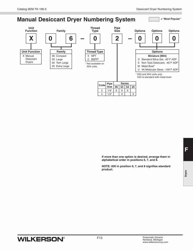
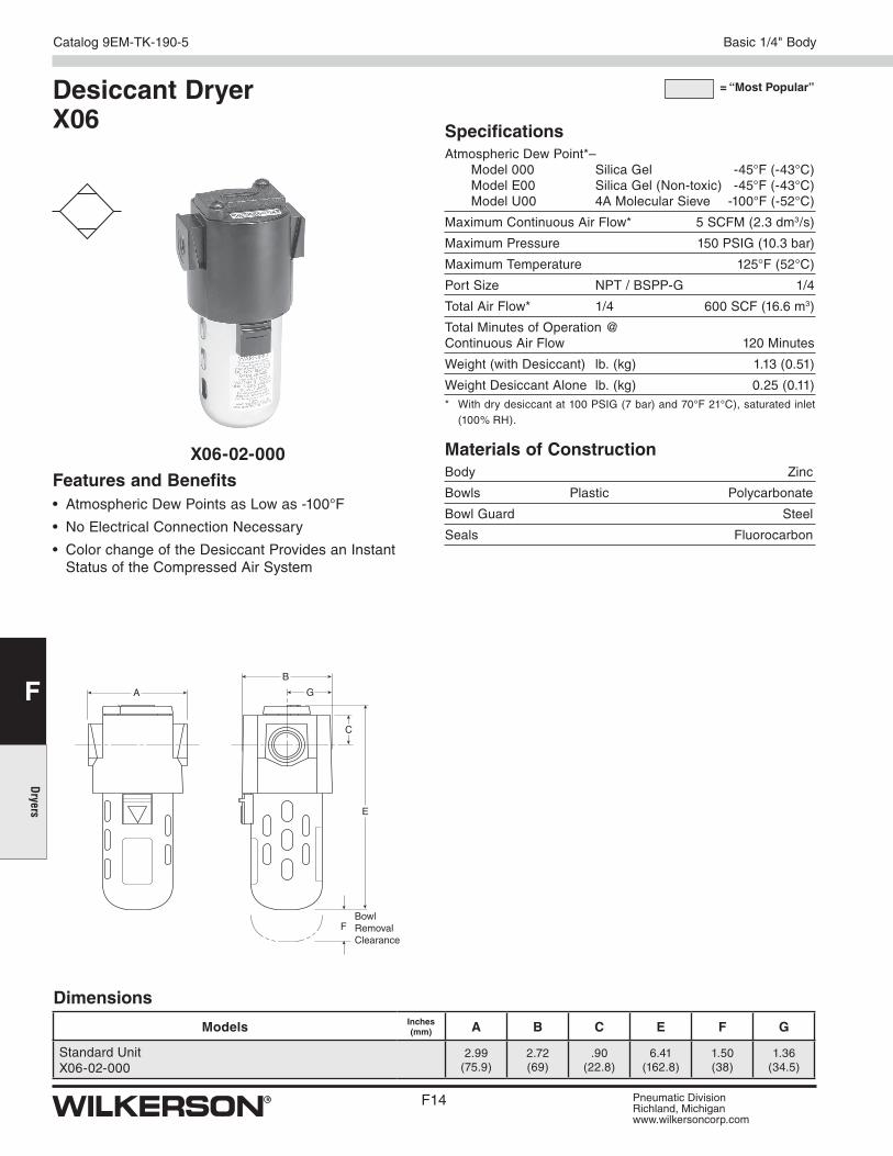
Desiccant Dryer X06
A
B
G
C
E
FBowlRemovalClearance
Dimensions
Models Inches (mm) A B C E F G
Standard UnitX06-02-000
2.99(75.9)
2.72(69)
.90(22.8)
6.41(162.8)
1.50 (38)
1.36 (34.5)
X06-02-000
= “Most Popular”
SpecificationsAtmospheric Dew Point*– Model 000 Silica Gel -45°F (-43°C) Model E00 Silica Gel (Non-toxic) -45°F (-43°C) Model U00 4A Molecular Sieve -100°F (-52°C)
Maximum Continuous Air Flow* 5 SCFM (2.3 dm3/s)
Maximum Pressure 150 PSIG (10.3 bar)
Maximum Temperature 125°F (52°C)
Port Size NPT / BSPP-G 1/4
Total Air Flow* 1/4 600 SCF (16.6 m3)
Total Minutes of Operation @ Continuous Air Flow 120 Minutes
Weight (with Desiccant) lb. (kg) 1.13 (0.51)
Weight Desiccant Alone lb. (kg) 0.25 (0.11)* With dry desiccant at 100 PSIG (7 bar) and 70°F 21°C), saturated inlet
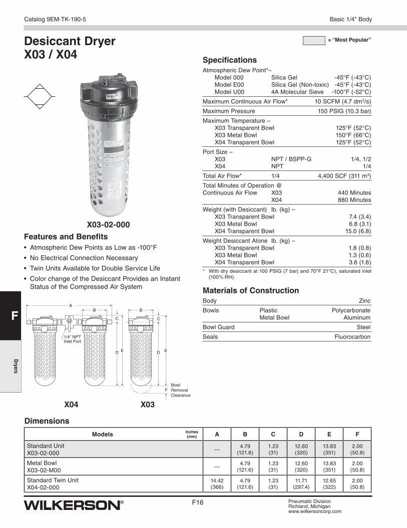
Features and Benefits• Atmospheric Dew Points as Low as -100°F
• No Electrical Connection Necessary
• Twin Units Available for Double Service Life
• Color change of the Desiccant Provides an Instant Status of the Compressed Air System
Desiccant Dryer X03 / X04
Dimensions
Models Inches (mm) A B C D E F
Standard UnitX03-02-000
—4.79
(121.6)1.23(31)
12.60 (320)
13.83(351)
2.00 (50.8)
Metal BowlX03-02-M00
—4.79
(121.6)1.23(31)
12.60 (320)
13.83(351)
2.00 (50.8)
Standard Twin UnitX04-02-000
14.42(366)
4.79 (121.6)
1.23(31)
11.71 (297.4)
12.65(322)
2.00 (50.8)
X03-02-000
= “Most Popular”
SpecificationsAtmospheric Dew Point*– Model 000 Silica Gel -45°F (-43°C) Model E00 Silica Gel (Non-toxic) -45°F (-43°C) Model U00 4A Molecular Sieve -100°F (-52°C)
Maximum Continuous Air Flow* 10 SCFM (4.7 dm3/s)
Maximum Pressure 150 PSIG (10.3 bar)
Maximum Temperature – X03 Transparent Bowl 125° F (52° C) X03 Metal Bowl 150°F (66°C) X04 Transparent Bowl 125° F (52 °C)
Port Size – X03 NPT / BSPP-G 1/4, 1/2 X04 NPT 1/4
Total Air Flow* 1/4 4,400 SCF (311 m3)
Total Minutes of Operation @ Continuous Air Flow X03 440 Minutes X04 880 Minutes
Tube Assembly with Screen – X03 / X04 Transparent Bowl ............................... DRP-96-435 X03 Metal Bowl ................................................... DRP-96-451* The Moisture Indicator contains a weep orifice to provide an air sample to
the moisture indicating paper. Air bleed from this indicator is necessary and normal.
= “Most Popular”
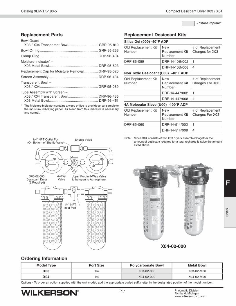
Ordering InformationModel Type Port Size Polycarbonate Bowl Metal Bowl
X03 1/4 X03-02-000 X03-02-M00
X04 1/4 X04-02-000 X04-02-M00
Options - To order an option supplied with the unit model, add the appropriate coded suffix letter in the designated position of the model number.
X03-02-000Desiccant Dryer
(2 Required)
4-WayValve
Shuttle Valve1/4" NPT Outlet Port(On Bottom of Shuttle Valve)
Upper Port in 4-Way Valveto be open to Atmosphere
1/4" NPTInlet Port
X04-02-000
Compact Desiccant Dryer X03 / X04
Note: Since X04 consists of two X03 dryers assembled together the amount of desiccant required for a total recharge is twice the amount listed above.
Replacement Desiccant KitsSilica Gel (000) -40°F ADP
Tube Assembly with Screen .................................. DRP-95-622* The Moisture Indicator contains a weep orifice to provide an air sample to
the moisture indicating paper. Air bleed from this indicator is necessary and normal.
Ordering InformationModel Type Port Size Metal Bowl
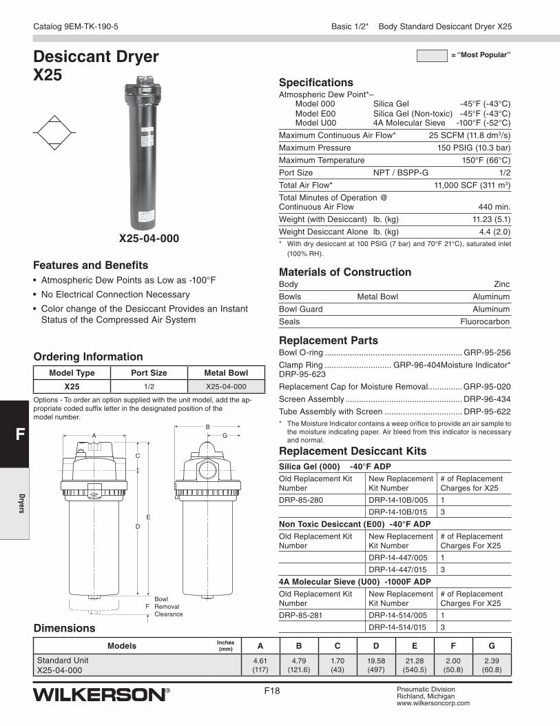
X25 1/2 X25-04-000
Options - To order an option supplied with the unit model, add the ap-propriate coded suffix letter in the designated position of the model number.
Features and Benefits• Atmospheric Dew Points as Low as -100°F
• No Electrical Connection Necessary
• Color change of the Desiccant Provides an Instant Status of the Compressed Air System
Desiccant Dryer X25
Dimensions
Models Inches (mm) A B C D E F G
Standard UnitX25-04-000
4.61 (117)
4.79(121.6)
1.70(43)
19.58 (497)
21.28(540.5)
2.00(50.8)
2.39(60.8)
SpecificationsAtmospheric Dew Point*– Model 000 Silica Gel -45°F (-43°C) Model E00 Silica Gel (Non-toxic) -45°F (-43°C) Model U00 4A Molecular Sieve -100°F (-52°C)
Maximum Continuous Air Flow* 25 SCFM (11.8 dm3/s)
Maximum Pressure 150 PSIG (10.3 bar)
Maximum Temperature 150°F (66°C)
Port Size NPT / BSPP-G 1/2
Total Air Flow* 11,000 SCF (311 m3)
Total Minutes of Operation @ Continuous Air Flow 440 min.
Weight (with Desiccant) lb. (kg) 11.23 (5.1)
Weight Desiccant Alone lb. (kg) 4.4 (2.0)* With dry desiccant at 100 PSIG (7 bar) and 70°F 21°C), saturated inlet
(100% RH).
Materials of ConstructionBody Zinc
Bowls Metal Bowl Aluminum
Bowl Guard Aluminum
Seals Fluorocarbon
X25-04-000
= “Most Popular”
A
C
D
BG
E
PressTurn
FBowl Removal Clearance
Basic 1/2" Body Standard Desiccant Dryer X25
Replacement Desiccant KitsSilica Gel (000) -40°F ADPOld Replacement Kit Number
New Replacement Kit Number
# of Replacement Charges for X25
DRP-85-280 DRP-14-10B/005 1
DRP-14-10B/015 3
Non Toxic Desiccant (E00) -40°F ADPOld Replacement Kit Number
New Replacement Kit Number
# of Replacement Charges For X25
DRP-14-447/005 1
DRP-14-447/015 3
4A Molecular Sieve (U00) -1000F ADPOld Replacement Kit Number
Drying compressed air through adsorption represents a purely physical process in which water vapor (adsorbate) is bound to the drying medium (adsorbent) through binding forces of molecular adhesion. Adsorbents are solids in spherical and granular form which are permeated by an array of pores. The water vapor is deposited onto the internal and external surface of the adsorption medium, without the formation of chemical compounds taking place, therefore the adsorption medium does not have to be replenished but only periodically regenerated.
HeatlessThe layout of adsorption dryers with heatless regeneration is clear and simple. Compared with other adsorption dryer systems, pressure dewpoints down to -100°F (-73°C) can be achieved without additional effort.
Use in the higher pressure ranges and at low inlet temperatures causes the quantity of air needed for desorption to be reduced to an economical value.
What is adsorption drying?At low operating pressure the demand for already dried compressed air for purposes of regeneration is increased. This increase causes a large proportion of the prepared compressed air to be no longer available for productive purposes.
Depending on the cycle, the quantity of air enclosed in the adsorber expands upon release at regular intervals with an emission noise level of about 90-95dB(A). Given suitable noise attenuation measures, a reduction of the noise emission level to the region of 10-15 dB(A) can be accomplished.
The use of adsorption dryers with heatless regeneration is preferred in the following applications:
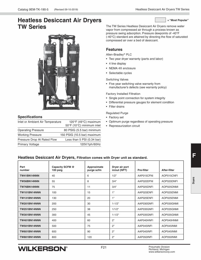
SpecificationsInlet or Ambient Air Temperature 120°F (49°C) maximum 50°F (10°C) minimum inlet
Operating Pressure 80 PSIG (5.5 bar) minimum
Working Pressure 150 PSIG (10.5 bar) maximum
Pressure Drop At Rated Flow Less than 5 PSI (0.34 bar)
Primary Voltage 120V/1ph/60Hz
The TW Series Heatless Desiccant Air Dryers remove water vapor from compressed air through a process known as pressure swing adsorption. Pressure dewpoints of -40°F (-40°C) standard are attained by directing the flow of saturated compressed air over a bed of desiccant.
FeaturesAllen-Bradley® PLC• Two year dryer warranty (parts and labor)
• 4 line display
• NEMA 4X enclosure
• Selectable cycles
Switching Valves• Five year switching valve warranty from
manufacturer’s defects (see warranty policy)
Factory Installed Filtration• Single point connection for system integrity• Differential pressure gauges for element condition• Filter drains
Heatless Desiccant Air Dryers TW Series (Revised 09-10-2019)
Additional Features• Separate tower pressure gauges
• OSHA approved mufflers with safety relief
• ASME/CRN vessels (TW101 and larger)
• Desiccant fill and drain ports
• Safety relief valves
• Stainless steel diffuser screens
• CycleLoc® demand control
• Control air line filter
• ETL listed (UL/CSA standards)
• LED din connector(s) all solenoid valves
• 120 VAC power (other options available - consult factory)
• Power cord with basic controller
• Power din connector with advanced controller
• Power On/Off switch with advanced controller
• Steel base TW1001 and larger
Options• PowerLoc Energy Demand Control (TW41 - TW801) optional
• All NEMA classifications
• Control air tubing - stainless steel
• Low ambient package (-20°F to +40°F air temperature)
• Instrumentation
• Locally mounted pressure and temperature gauges at inlet and outlet
• Pneumatic controls
• ASME B31.3 piping
• Corrosion allowance
• High pressure applications: 200 psig design & 250 psig design adders are available
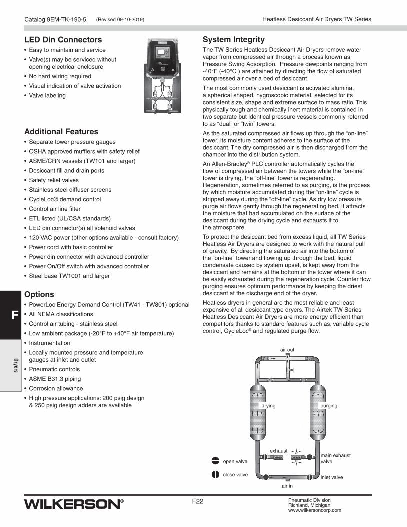
LED Din Connectors• Easy to maintain and service
• Valve(s) may be serviced without opening electrical enclosure
• No hard wiring required
• Visual indication of valve activation
• Valve labeling
air out
open valve
close valve
air in
exhaust
drying purging
main exhaust valve
inlet valve
System IntegrityThe TW Series Heatless Desiccant Air Dryers remove water vapor from compressed air through a process known as Pressure Swing Adsorption. Pressure dewpoints ranging from -40°F (-40°C ) are attained by directing the flow of saturated compressed air over a bed of desiccant.
The most commonly used desiccant is activated alumina, a spherical shaped, hygroscopic material, selected for its consistent size, shape and extreme surface to mass ratio. This physically tough and chemically inert material is contained in two separate but identical pressure vessels commonly referred to as “dual” or “twin” towers.
As the saturated compressed air flows up through the “on-line” tower, its moisture content adheres to the surface of the desiccant. The dry compressed air is then discharged from the chamber into the distribution system.
An Allen-Bradley® PLC controller automatically cycles the flow of compressed air between the towers while the “on-line” tower is drying, the “off-line” tower is regenerating. Regeneration, sometimes referred to as purging, is the process by which moisture accumulated during the “on-line” cycle is stripped away during the “off-line” cycle. As dry low pressure purge air flows gently through the regenerating bed, it attracts the moisture that had accumulated on the surface of the desiccant during the drying cycle and exhausts it to the atmosphere.
To protect the desiccant bed from excess liquid, all TW Series Heatless Air Dryers are designed to work with the natural pull of gravity. By directing the saturated air into the bottom of the “on-line” tower and flowing up through the bed, liquid condensate caused by system upset, is kept away from the desiccant and remains at the bottom of the tower where it can be easily exhausted during the regeneration cycle. Counter flow purging ensures optimum performance by keeping the driest desiccant at the discharge end of the dryer.
Heatless dryers in general are the most reliable and least expensive of all desiccant type dryers. The Airtek TW Series Heatless Desiccant Air Dryers are more energy efficient than competitors thanks to standard features such as: variable cycle control, CycleLoc® and regulated purge flow.
Heatless Desiccant Air Dryers TW Series (Revised 09-10-2019)
• Allen-Bradley® PLC• Powerloc® Energy Demand System
- Energy savings percentage - Hours in power save
• Nema 4X enclosure• 3.5" LCD user interface• Dew point sensor input (-148°F to 68°F)• Optional 4-20 mA output for remotely monitoring dew point • Tower pressure sensors• Inlet pressure and temperature sensors• Compressor demand via external dry contact (CycleLoc®)• Modbus/TCP communications via standard ethernet port• Modbus RTU communications via optional RS232/485 port
(Using external gateway device) • SD card slot for accessing historical data and alarm
information• Selectable cycle settings• Programmable drain timer (drain on, time and test)• User selectable alarms with common alarm relay
- High inlet temperature - Low inlet pressure - Tower failed to blow down (switch failure) - Tower failed to pressurize - High dew point - Sensor failure for all sensors - Switch failure - Inlet filter pressure
• Filter maintenance timer & alarm• Clogged muffler maintenance and alarm• Power ON/OFF switch• Alarm log stores most recent alarms• Flashes green when in energy savings mode• Flashes red when an alarm is present• Dry contact for common alarm
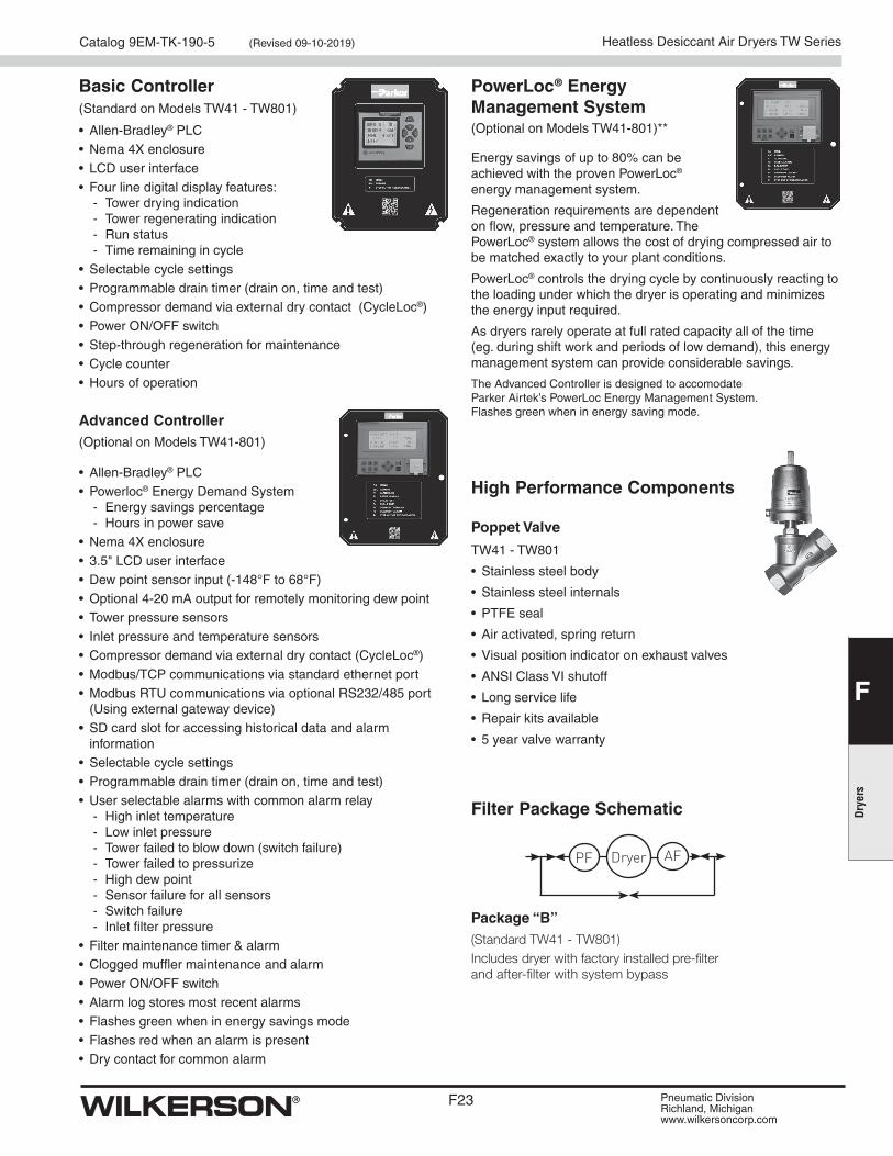
Basic Controller(Standard on Models TW41 - TW801)
Advanced Controller(Optional on Models TW41-801)
• Allen-Bradley® PLC• Nema 4X enclosure• LCD user interface• Four line digital display features:
- Tower drying indication - Tower regenerating indication - Run status - Time remaining in cycle
• Selectable cycle settings• Programmable drain timer (drain on, time and test)• Compressor demand via external dry contact (CycleLoc®)• Power ON/OFF switch• Step-through regeneration for maintenance• Cycle counter• Hours of operation
High Performance Components
Energy savings of up to 80% can be achieved with the proven PowerLoc® energy management system.
Regeneration requirements are dependent on flow, pressure and temperature. The PowerLoc® system allows the cost of drying compressed air to be matched exactly to your plant conditions.
PowerLoc® controls the drying cycle by continuously reacting to the loading under which the dryer is operating and minimizes the energy input required.
As dryers rarely operate at full rated capacity all of the time (eg. during shift work and periods of low demand), this energy management system can provide considerable savings.
The Advanced Controller is designed to accomodate Parker Airtek’s PowerLoc Energy Management System. Flashes green when in energy saving mode.
PowerLoc® Energy Management System
Poppet Valve
TW41 - TW801
• Stainless steel body
• Stainless steel internals
• PTFE seal
• Air activated, spring return
• Visual position indicator on exhaust valves
• ANSI Class VI shutoff
• Long service life
• Repair kits available
• 5 year valve warranty
(Optional on Models TW41-801)**
Filter Package Schematic
Package “B” (Standard TW41 - TW801) Includes dryer with factory installed pre-filter and after-filter with system bypass
Ambient Operating Range Temperature: 34° to 130°F (1.1° to 54°C)
Coil Insulation Class H 340°F (171.1°C)
Voltages AC 115, 230/50-60
Timer: Open Time .5 to 10 sec., Adjustable Cycle Time .5 sec. to 45 min., Adjustable
Maximum Current Rating 4mA Max.
Port Size 1/4, 3/8, 1/2 NPT
Weight 1.8 lb. (0.8 kg)
Materials of ConstructionValve Body Brass / Stainless Steel
Enclosure (NEMA 4) ABS Plastic
Internal Parts Brass / Stainless Steel
Sealing Material FPM (Fluorocarbon)
A
B
C
ON OFFTEST
510 20 30
40450.6 ohm
24 6
8100.5 0 Pipe Valve
Family Voltage Size Material Pressure
WDV3 – G 1 2 B L
Pressure
L 230 PSIG (16 bar)
Valve Material
B Brass
Family
G General
Voltage
1 120V AC 2 230V AC 3* 24VDC
Pipe Size
2 1/4" General 3 3/8" General 4 1/2" General
Ordering Information
Model Selection and Dimensions
Model Number
A B C
WDV3-G**BL1.73
(44)
4.53
(115)
3.46
(88)
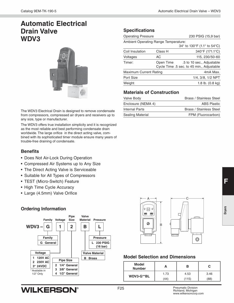
The WDV3 Electrical Drain is designed to remove condensate from compressors, compressed air dryers and receivers up to any size, type or manufacturer.
The WDV3 offers true installation simplicity and it is recognized as the most reliable and best performing condensate drain worldwide. The large orifice in the direct acting valve, com-bined with its sophisticated timer module ensure many years of trouble-free draining of condensate.
Benefits• Does Not Air-Lock During Operation• Compressed Air Systems up to Any Size• The Direct Acting Valve is Serviceable• Suitable for All Types of Compressors• TEST (Micro-Switch) Feature• High Time Cycle Accuracy• Large (4.5mm) Valve Orifice
Ambient Operating Range Temperature: 35° to 140°F (1.6° to 60°C)
Voltages NPT 115/50-60Hz Standard BSPP 230/50-60Hz & 24VDC Optional
Zero Air Loss Condensate Drain – ED
Zero Air Loss Condensate Drain ED Zero air loss condensate drains are designed for economical
removal of unwanted water, oil emulsions, and other liquids. These drains will only open when liquid is present and will not allow any compressed air to escape from the system.
Compressor with Aftercooler Receiver Tank Filter Air Dryer Drip Leg
Removes the condensate that is collected after the air cools in the aftercooler
Removes the condensate that is collected when the air cools inside of the receiver tank
Removes the condensate that is collected in the filter bowl
Removes the condensate that is collected in the air dryer
Point-of-use applications: removes the condensate from compressed air pipes in a plant
Where are Condensate Drains Used?
Zero Air Loss Condensate Drains
Port size (NPT)
Compressor Aftercooler (SCFM)*
Capacity Refrigeration Dryer (SCFM)**
Filter (SCFM)
Drain Capacity per Day (gal/liter) Model Number Service Kit
* Based on 100 PSI working pressure, air compressor inlet at 77°F (25°C) at 60% RH, air discharge temperature od 95°F (35°C) following the aftercooler, pressure dewpoint of 37°F (2.8°C) after the refrigerated dryer.
** Condensate from aftercooler or refrigerated dryer to be drained upstream – only for residual oil content or small quantities of condensate.
Note: A 6 ft. line cord will be included with each drain.
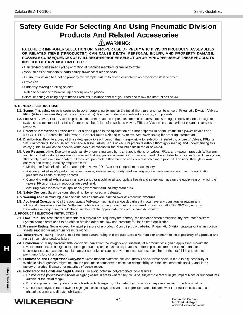
Safety Guide For Selecting And Using Pneumatic DivisionProducts And Related Accessories
WARNING:FAILURE OR IMPROPER SELECTION OR IMPROPER USE OF PNEUMATIC DIVISION PRODUCTS, ASSEMBLIES OR RELATED ITEMS (“PRODUCTS”) CAN CAUSE DEATH, PERSONAL INJURY, AND PROPERTY DAMAGE. POSSIBLE CONSEQUENCES OF FAILURE OR IMPROPER SELECTION OR IMPROPER USE OF THESE PRODUCTS INCLUDE BUT ARE NOT LIMITED TO:• Unintended or mistimed cycling or motion of machine members or failure to cycle
• Work pieces or component parts being thrown off at high speeds.
• Failure of a device to function properly for example, failure to clamp or unclamp an associated item or device.
• Explosion
• Suddenly moving or falling objects.
• Release of toxic or otherwise injurious liquids or gasses.
Before selecting or using any of these Products, it is important that you read and follow the instructions below.
!
Safety Guidelines
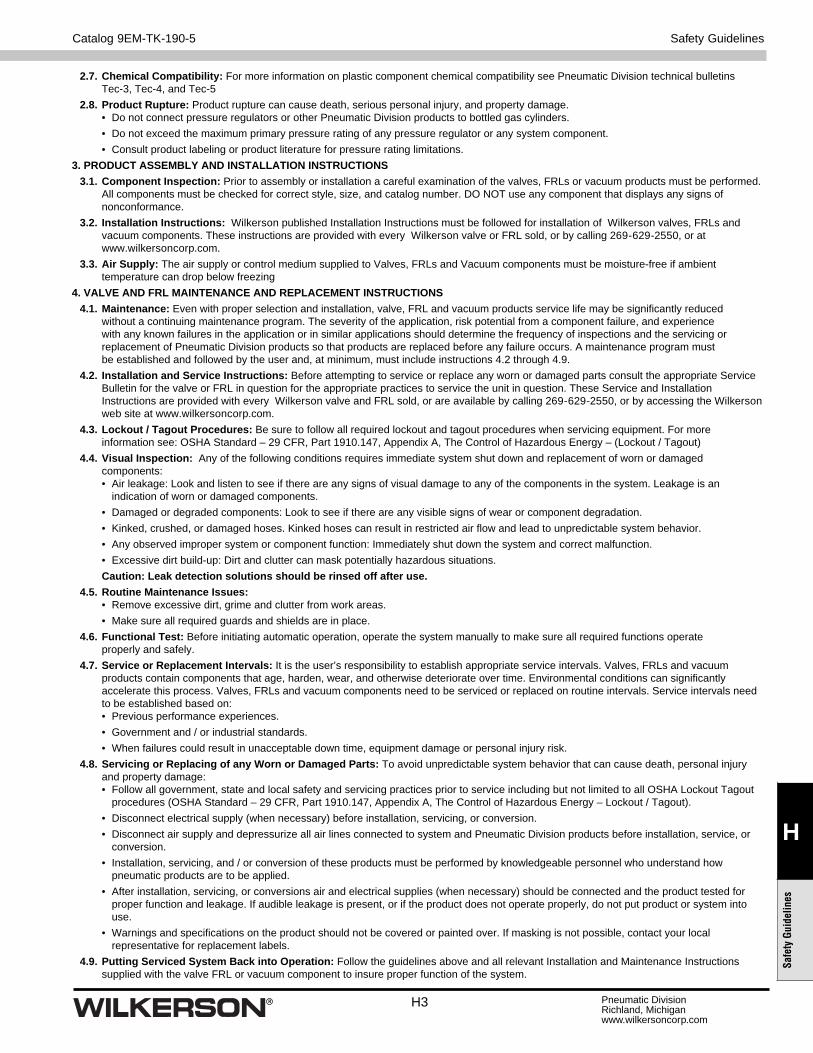
1. GENERAL INSTRUCTIONS 1.1. Scope: This safety guide is designed to cover general guidelines on the installation, use, and maintenance of Pneumatic Division Valves,
FRLs (Filters pressure Regulators and Lubricators), Vacuum products and related accessory components. 1.2. Fail-Safe: Valves, FRLs, Vacuum products and their related components can and do fail without warning for many reasons. Design all
systems and equipment in a fail-safe mode, so that failure of associated valves, FRLs or Vacuum products will not endanger persons or property.
1.3 Relevant International Standards: For a good guide to the application of a broad spectrum of pneumatic fl uid power devices see: ISO 4414:1998, Pneumatic Fluid Power – General Rules Relating to Systems. See www.iso.org for ordering information.
1.4. Distribution: Provide a copy of this safety guide to each person that is responsible for selection, installation, or use of Valves, FRLs or Vacuum products. Do not select, or use Wilkerson valves, FRLs or vacuum products without thoroughly reading and understanding this safety guide as well as the specifi c Wilkerson publications for the products considered or selected.
1.5. User Responsibility: Due to the wide variety of operating conditions and applications for valves, FRLs, and vacuum products Wilkerson and its distributors do not represent or warrant that any particular valve, FRL or vacuum product is suitable for any specifi c end use system. This safety guide does not analyze all technical parameters that must be considered in selecting a product. The user, through its own analysis and testing, is solely responsible for: • Making the fi nal selection of the appropriate valve, FRL, Vacuum component, or accessory.
• Assuring that all user’s performance, endurance, maintenance, safety, and warning requirements are met and that the application presents no health or safety hazards.
• Complying with all existing warning labels and / or providing all appropriate health and safety warnings on the equipment on which the valves, FRLs or Vacuum products are used; and,
• Assuring compliance with all applicable government and industry standards. 1.6. Safety Devices: Safety devices should not be removed, or defeated. 1.7. Warning Labels: Warning labels should not be removed, painted over or otherwise obscured. 1.8. Additional Questions: Call the appropriate Wilkerson technical service department if you have any questions or require any
additional information. See the Wilkerson publication for the product being considered or used, or call 269-629-2550, or go to www.wilkersoncorp.com, for telephone numbers of the appropriate technical service department.
2. PRODUCT SELECTION INSTRUCTIONS 2.1. Flow Rate: The fl ow rate requirements of a system are frequently the primary consideration when designing any pneumatic system.
System components need to be able to provide adequate fl ow and pressure for the desired application. 2.2. Pressure Rating: Never exceed the rated pressure of a product. Consult product labeling, Pneumatic Division catalogs or the instruction
sheets supplied for maximum pressure ratings. 2.3. Temperature Rating: Never exceed the temperature rating of a product. Excessive heat can shorten the life expectancy of a product and
result in complete product failure. 2.4. Environment: Many environmental conditions can affect the integrity and suitability of a product for a given application. Pneumatic
Division products are designed for use in general purpose industrial applications. If these products are to be used in unusual circumstances such as direct sunlight and/or corrosive or caustic environments, such use can shorten the useful life and lead to premature failure of a product.
2.5. Lubrication and Compressor Carryover: Some modern synthetic oils can and will attack nitrile seals. If there is any possibility of synthetic oils or greases migrating into the pneumatic components check for compatibility with the seal materials used. Consult the factory or product literature for materials of construction.
2.6. Polycarbonate Bowls and Sight Glasses: To avoid potential polycarbonate bowl failures: • Do not locate polycarbonate bowls or sight glasses in areas where they could be subject to direct sunlight, impact blow, or temperatures outside of the rated range.
• Do not expose or clean polycarbonate bowls with detergents, chlorinated hydro-carbons, keytones, esters or certain alcohols. • Do not use polycarbonate bowls or sight glasses in air systems where compressors are lubricated with fire resistant fluids such as
2.7. Chemical Compatibility: For more information on plastic component chemical compatibility see Pneumatic Division technical bulletins Tec-3, Tec-4, and Tec-5
2.8. Product Rupture: Product rupture can cause death, serious personal injury, and property damage. • Do not connect pressure regulators or other Pneumatic Division products to bottled gas cylinders.
• Do not exceed the maximum primary pressure rating of any pressure regulator or any system component.
• Consult product labeling or product literature for pressure rating limitations.
3. PRODUCT ASSEMBLY AND INSTALLATION INSTRUCTIONS
3.1. Component Inspection: Prior to assembly or installation a careful examination of the valves, FRLs or vacuum products must be performed. All components must be checked for correct style, size, and catalog number. DO NOT use any component that displays any signs of nonconformance.
3.2. Installation Instructions: Wilkerson published Installation Instructions must be followed for installation of Wilkerson valves, FRLs and vacuum components. These instructions are provided with every Wilkerson valve or FRL sold, or by calling 269-629-2550, or at www.wilkersoncorp.com.
3.3. Air Supply: The air supply or control medium supplied to Valves, FRLs and Vacuum components must be moisture-free if ambient temperature can drop below freezing
4. VALVE AND FRL MAINTENANCE AND REPLACEMENT INSTRUCTIONS
4.1. Maintenance: Even with proper selection and installation, valve, FRL and vacuum products service life may be significantly reduced without a continuing maintenance program. The severity of the application, risk potential from a component failure, and experience with any known failures in the application or in similar applications should determine the frequency of inspections and the servicing or replacement of Pneumatic Division products so that products are replaced before any failure occurs. A maintenance program must be established and followed by the user and, at minimum, must include instructions 4.2 through 4.9.
4.2. Installation and Service Instructions: Before attempting to service or replace any worn or damaged parts consult the appropriate Service Bulletin for the valve or FRL in question for the appropriate practices to service the unit in question. These Service and Installation Instructions are provided with every Wilkerson valve and FRL sold, or are available by calling 269-629-2550, or by accessing the Wilkerson web site at www.wilkersoncorp.com.
4.3. Lockout / Tagout Procedures: Be sure to follow all required lockout and tagout procedures when servicing equipment. For more information see: OSHA Standard – 29 CFR, Part 1910.147, Appendix A, The Control of Hazardous Energy – (Lockout / Tagout)
4.4. Visual Inspection: Any of the following conditions requires immediate system shut down and replacement of worn or damaged components: • Air leakage: Look and listen to see if there are any signs of visual damage to any of the components in the system. Leakage is an indication of worn or damaged components.
• Damaged or degraded components: Look to see if there are any visible signs of wear or component degradation.
• Kinked, crushed, or damaged hoses. Kinked hoses can result in restricted air flow and lead to unpredictable system behavior.
• Any observed improper system or component function: Immediately shut down the system and correct malfunction.
• Excessive dirt build-up: Dirt and clutter can mask potentially hazardous situations.
Caution: Leak detection solutions should be rinsed off after use.
4.5. Routine Maintenance Issues: • Remove excessive dirt, grime and clutter from work areas.
• Make sure all required guards and shields are in place.
4.6. Functional Test: Before initiating automatic operation, operate the system manually to make sure all required functions operate properly and safely.
4.7. Service or Replacement Intervals: It is the user’s responsibility to establish appropriate service intervals. Valves, FRLs and vacuum products contain components that age, harden, wear, and otherwise deteriorate over time. Environmental conditions can significantly accelerate this process. Valves, FRLs and vacuum components need to be serviced or replaced on routine intervals. Service intervals need to be established based on: • Previous performance experiences.
• Government and / or industrial standards.
• When failures could result in unacceptable down time, equipment damage or personal injury risk.
4.8. Servicing or Replacing of any Worn or Damaged Parts: To avoid unpredictable system behavior that can cause death, personal injury and property damage: • Follow all government, state and local safety and servicing practices prior to service including but not limited to all OSHA Lockout Tagout procedures (OSHA Standard – 29 CFR, Part 1910.147, Appendix A, The Control of Hazardous Energy – Lockout / Tagout).
• Disconnect electrical supply (when necessary) before installation, servicing, or conversion.
• Disconnect air supply and depressurize all air lines connected to system and Pneumatic Division products before installation, service, or conversion.
• Installation, servicing, and / or conversion of these products must be performed by knowledgeable personnel who understand how pneumatic products are to be applied.
• After installation, servicing, or conversions air and electrical supplies (when necessary) should be connected and the product tested for proper function and leakage. If audible leakage is present, or if the product does not operate properly, do not put product or system into use.
• Warnings and specifications on the product should not be covered or painted over. If masking is not possible, contact your local representative for replacement labels.
4.9. Putting Serviced System Back into Operation: Follow the guidelines above and all relevant Installation and Maintenance Instructions supplied with the valve FRL or vacuum component to insure proper function of the system.
Claims and Shortages: Risk of loss passes to buyer when goods are delivered to the carrier. Inspect all shipments for damage at time of receipt. Claims should be fi led by the consignee against the carrier.
Changes: Wilkerson maintains a policy of ongoing product development and improvement. We therefore reserve the right to change dimensions, specifi cations and design without notice.
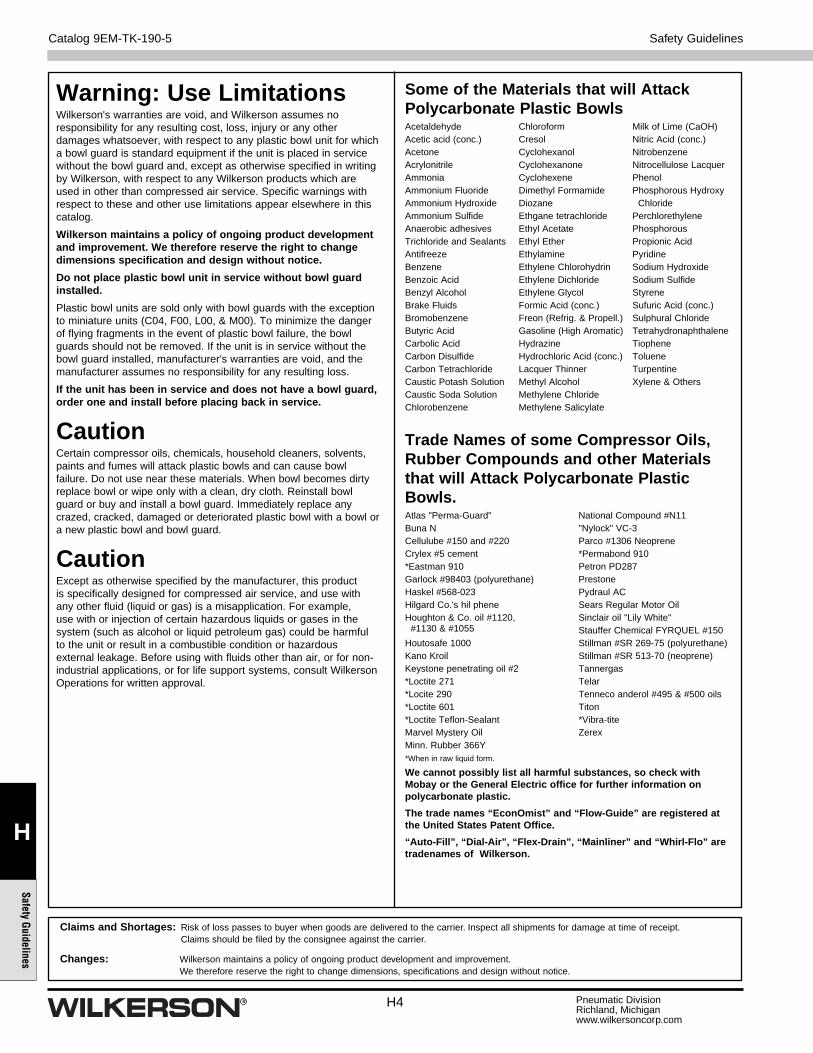
Warning: Use LimitationsWilkerson's warranties are void, and Wilkerson assumes no responsibility for any resulting cost, loss, injury or any other damages whatsoever, with respect to any plastic bowl unit for which a bowl guard is standard equipment if the unit is placed in service without the bowl guard and, except as otherwise specifi ed in writing by Wilkerson, with respect to any Wilkerson products which are used in other than compressed air service. Specifi c warnings with respect to these and other use limitations appear elsewhere in this catalog.
Wilkerson maintains a policy of ongoing product development and improvement. We therefore reserve the right to change dimensions specifi cation and design without notice.
Do not place plastic bowl unit in service without bowl guard installed.
Plastic bowl units are sold only with bowl guards with the exception to miniature units (C04, F00, L00, & M00). To minimize the danger of fl ying fragments in the event of plastic bowl failure, the bowl guards should not be removed. If the unit is in service without the bowl guard installed, manufacturer's warranties are void, and the manufacturer assumes no responsibility for any resulting loss.
If the unit has been in service and does not have a bowl guard, order one and install before placing back in service.
CautionCertain compressor oils, chemicals, household cleaners, solvents, paints and fumes will attack plastic bowls and can cause bowl failure. Do not use near these materials. When bowl becomes dirty replace bowl or wipe only with a clean, dry cloth. Reinstall bowl guard or buy and install a bowl guard. Immediately replace any crazed, cracked, damaged or deteriorated plastic bowl with a bowl or a new plastic bowl and bowl guard.
CautionExcept as otherwise specifi ed by the manufacturer, this product is specifi cally designed for compressed air service, and use with any other fl uid (liquid or gas) is a misapplication. For example, use with or injection of certain hazardous liquids or gases in the system (such as alcohol or liquid petroleum gas) could be harmful to the unit or result in a combustible condition or hazardous external leakage. Before using with fl uids other than air, or for non-industrial applications, or for life support systems, consult Wilkerson Operations for written approval.
1. Terms and Conditions. Seller’s willingness to offer Products for sale or accept an order
for Products is subject to the terms and conditions contained in this Offer of Sale or any
newer version of the same, published by Seller electronically at www.parker.com/saleterms/.
Seller objects to any contrary or additional terms or conditions of Buyer’s order or any other
document or other communication issued by Buyer.
2. Price; Payment. Prices stated on Seller’s Quote are valid for thirty (30) days, except
as explicitly otherwise stated therein, and do not include any sales, use, or other taxes or
duties unless specifi cally stated. Seller reserves the right to modify prices to adjust for any
raw material price fl uctuations. Unless otherwise specifi ed by Seller, all prices are F.C.A.
Seller’s facility (INCOTERMS 2010). Payment is subject to credit approval and payment for
all purchases is due thirty (30) days from the date of invoice (or such date as may be specifi ed
by Seller’s Credit Department). Unpaid invoices beyond the specifi ed payment date incur
interest at the rate of 1.5% per month or the maximum allowable rate under applicable law.
3. Shipment; Delivery; Title and Risk of Loss. All delivery dates are approximate.
Seller is not responsible for damages resulting from any delay. Regardless of the manner of
shipment, delivery occurs and title and risk of loss or damage pass to Buyer, upon placement
of the Products with the shipment carrier at Seller’s facility. Unless otherwise stated, Seller
may exercise its judgment in choosing the carrier and means of delivery. No deferment of
shipment at Buyers’ request beyond the respective dates indicated will be made except
on terms that will indemnify, defend and hold Seller harmless against all loss and additional
expense. Buyer shall be responsible for any additional shipping charges incurred by Seller
due to Buyer’s acts or omissions.
4. Warranty. Seller warrants that the Products sold hereunder shall be free from
defects in material or workmanship for a period of twelve (12) months from the
date of delivery or 2,000 hours of normal use, whichever occurs fi rst. All prices are
based upon the exclusive limited warranty stated above, and upon the following
disclaimer: DISCLAIMER OF WARRANTY: THIS WARRANTY IS THE SOLE AND
ENTIRE WARRANTY PERTAINING TO PRODUCTS PROVIDED. SELLER DISCLAIMS
ALL OTHER WARRANTIES, EXPRESS AND IMPLIED, INCLUDING DESIGN,
MERCHANTABILITY AND FITNESS FOR A PARTICULAR PURPOSE.
5. Claims; Commencement of Actions. Buyer shall promptly inspect all Products
upon receipt. No claims for shortages will be allowed unless reported to the Seller within
ten (10) days of delivery. No other claims against Seller will be allowed unless asserted in
writing within thirty (30) days after delivery. Buyer shall notify Seller of any alleged breach of
warranty within thirty (30) days after the date the defect is or should have been discovered by
Buyer. Any claim or action against Seller based upon breach of contract or any other theory,
including tort, negligence, or otherwise must be commenced within twelve (12) months from
the date of the alleged breach or other alleged event, without regard to the date of discovery.
6. LIMITATION OF LIABILITY. IN THE EVENT OF A BREACH OF WARRANTY, SELLER
WILL, AT ITS OPTION, REPAIR OR REPLACE A DEFECTIVE PRODUCT, OR REFUND
THE PURCHASE PRICE WITHIN A REASONABLE PERIOD OF TIME. IN NO EVENT IS
SELLER LIABLE FOR ANY SPECIAL, INDIRECT, INCIDENTAL OR CONSEQUENTIAL
DAMAGES ARISING OUT OF, OR AS THE RESULT OF, THE SALE, DELIVERY, NON-
DELIVERY, SERVICING, USE OR LOSS OF USE OF THE PRODUCTS OR ANY PART
THEREOF, OR FOR ANY CHARGES OR EXPENSES OF ANY NATURE INCURRED
WITHOUT SELLER’S WRITTEN CONSENT, WHETHER BASED IN CONTRACT, TORT
OR OTHER LEGAL THEORY. IN NO EVENT SHALL SELLER’S LIABILITY UNDER ANY
CLAIM MADE BY BUYER EXCEED THE PURCHASE PRICE OF THE PRODUCTS.
7. User Responsibility. The user, through its own analysis and testing, is solely responsible
for making the fi nal selection of the system and Product and assuring that all performance,
endurance, maintenance, safety and warning requirements of the application are met. The
user must analyze all aspects of the application and follow applicable industry standards
and Product information. If Seller provides Product or system options based upon data or
specifi cations provided by the user, the user is responsible for determining that such data
and specifi cations are suitable and suffi cient for all applications and reasonably foreseeable
uses of the Products or systems.
8. Loss to Buyer’s Property. Any designs, tools, patterns, materials, drawings,
confi dential information or equipment furnished by Buyer or any other items which become
Buyer’s property, will be considered obsolete and may be destroyed by Seller after two (2)
consecutive years have elapsed without Buyer ordering the items manufactured using such
property. Seller shall not be responsible for any loss or damage to such property while it is in
Seller’s possession or control.
9. Special Tooling. A tooling charge may be imposed for any special tooling, including
without limitation, dies, fi xtures, molds and patterns, acquired to manufacture Products.
Such special tooling shall be and remain Seller’s property notwithstanding payment of any
charges by Buyer. In no event will Buyer acquire any interest in apparatus belonging to
Seller which is utilized in the manufacture of the Products, even if such apparatus has been
specially converted or adapted for such manufacture and notwithstanding any charges paid
by Buyer. Unless otherwise agreed, Seller has the right to alter, discard or otherwise dispose
of any special tooling or other property in its sole discretion at any time.
10. Buyer’s Obligation; Rights of Seller. To secure payment of all sums due or otherwise,
Seller retains a security interest in all Products delivered to Buyer and this agreement is
deemed to be a Security Agreement under the Uniform Commercial Code. Buyer authorizes
Seller as its attorney to execute and fi le on Buyer’s behalf all documents Seller deems
necessary to perfect its security interest.
11. Improper Use and Indemnity. Buyer shall indemnify, defend, and hold Seller harmless
from any losses, claims, liabilities, damages, lawsuits, judgments and costs (including
attorney fees and defense costs), whether for personal injury, property damage, patent,
The goods, services or work (referred to as the “Products”) offered by Parker-Hannifi n Corporation, its subsidiaries, groups, divisions, and authorized distributors (“Seller”) are offered for sale at prices indicated in the offer, or as may be established by Seller. The offer to sell the Products and acceptance of Seller’s offer by any customer (“Buyer”) is contingent upon, and will be governed by all of the terms and conditions contained in this Offer of Sale. Buyer’s order for any Products specifi ed in Buyer’s purchase document or Seller’s offer, proposal or quote (“Quote”) attached to the purchase order, when communicated to Seller verbally, or in writing, shall constitute acceptance of this offer.
trademark or copyright infringement or any other claim, brought by or incurred by Buyer,
Buyer’s employees, or any other person, arising out of: (a) improper selection, application,
design, specifi cation or other misuse of Products purchased by Buyer from Seller; (b) any act
or omission, negligent or otherwise, of Buyer; (c) Seller’s use of patterns, plans, drawings, or
specifi cations furnished by Buyer to manufacture Products; or (d) Buyer’s failure to comply
with these terms and conditions. Seller shall not indemnify Buyer under any circumstance
except as otherwise provided.
12. Cancellations and Changes. Buyer may not cancel or modify or cancel any order for
any reason, except with Seller’s written consent and upon terms that will indemnify, defend
and hold Seller harmless against all direct, incidental and consequential loss or damage.
Seller may change Product features, specifi cations, designs and availability.
13. Limitation on Assignment. Buyer may not assign its rights or obligations under this
agreement without the prior written consent of Seller.
14. Force Majeure. Seller does not assume the risk and is not liable for delay or failure
to perform any of Seller’s obligations by reason of events or circumstances beyond its
reasonable control (hereinafter “Events of Force Majeure”). Events of Force Majeure shall
include without limitation: accidents, strikes or labor disputes, acts of any government or
government agency, acts of nature, delays or failures in delivery from carriers or suppliers,
shortages of materials, or any other cause beyond Seller’s reasonable control.
15. Waiver a n d Severability. Failure to enforce any provision of this agreement will not
invalidate that provision; nor will any such failure prejudice Seller’s right to enforce that
provision in the future. Invalidation of any provision of this agreement by legislation or other
rule of law shall not invalidate any other provision herein. The remaining provisions of this
agreement will remain in full force and effect.
16. Termination. Seller may terminate this agreement for any reason and at any time
by giving Buyer thirty (30) days prior written notice. Seller may immediately terminate this
agreement, in writing, if Buyer: (a) breaches any provision of this agreement (b) appoints a
trustee, receiver or custodian for all or any part of Buyer’s property (c) fi les a petition for relief
in bankruptcy on its own behalf, or one if fi led by a third party (d) makes an assignment for
the benefi t of creditors; or (e) dissolves its business or liquidates all or a majority of its assets.
17. Governing Law. This agreement and the sale and delivery of all Products are deemed
to have taken place in, and shall be governed and construed in accordance with, the laws
of the State of Ohio, as applicable to contracts executed and wholly performed therein and
without regard to confl icts of laws principles. Buyer irrevocably agrees and consents to the
exclusive jurisdiction and venue of the courts of Cuyahoga County, Ohio with respect to any
dispute, controversy or claim arising out of or relating to this agreement.
18. Indemnity for Infringement of Intellectual Property Rights. Seller is not liable for
infringement of any patents, trademarks, copyrights, trade dress, trade secrets or similar
rights except as provided in this Section. Seller will defend and indemnify Buyer against
allegations of infringement of U.S. patents, U.S. trademarks, copyrights, trade dress and
trade secrets (“Intellectual Property Rights”). Seller will defend at its expense and will pay the
cost of any settlement or damages awarded in an action brought against Buyer based on an
allegation that a Product sold pursuant to this agreement infringes the Intellectual Property
Rights of a third party. Seller’s obligation to defend and indemnify Buyer is contingent on
Buyer notifying Seller within ten (10) days after Buyer becomes aware of such allegations of
infringement, and Seller having sole control over the defense of any allegations or actions
including all negotiations for settlement or compromise. If a Product is subject to a claim
that it infringes the Intellectual Property Rights of a third party, Seller may, at its sole expense
and option, procure for Buyer the right to continue using the Product, replace or modify the
Product so as to make it noninfringing, or offer to accept return of the Product and refund the
purchase price less a reasonable allowance for depreciation. Notwithstanding the foregoing,
Seller is not liable for claims of infringement based on information provided by Buyer, or
directed to Products delivered hereunder for which the designs are specifi ed in whole or part
by Buyer, or infringements resulting from the modifi cation, combination or use in a system of
any Product sold hereunder. The foregoing provisions of this Section constitute Seller’s sole
and exclusive liability and Buyer’s sole and exclusive remedy for infringement of Intellectual
Property Rights.
19. Entire Agreement. This agreement contains the entire agreement between the Buyer
and Seller and constitutes the fi nal, complete and exclusive expression of the terms of sale.
All prior or contemporaneous written or oral agreements or negotiations with respect to the
subject matter are herein merged. The terms contained herein may not be modifi ed unless
in writing and signed by an authorized representative of Seller.
20. Compliance with Laws. Buyer agrees to comply with all applicable laws, regulations,
and industry and professional standards of care, including those of the United Kingdom, the
United States of America, and the country or countries in which Buyer may operate, including
without limitation the U. K. Bribery Act, the U.S. Foreign Corrupt Practices Act (“FCPA”), the
U.S. Anti-Kickback Act (“Anti-Kickback Act”) and the U.S. Food Drug and Cosmetic Act
(“FDCA”),each as currently amended, and the rules and regulations promulgated by the U.S.
Food and Drug Administration (“FDA”), and agrees to indemnify and hold harmless Seller
from the consequences of any violation of such provisions by Buyer, its employees or agents.
Buyer acknowledges that it is familiar with the provisions of the U. K. Bribery Act, the FCPA,
the FDA, and the Anti-Kickback Act, and certifi es that Buyer will adhere to the requirements
thereof. In particular, Buyer represents and agrees that Buyer will not make any payment or
give anything of value, directly or indirectly to any governmental offi cial, any foreign political
party or offi cial thereof, any candidate for foreign political offi ce, or any commercial entity or
person, for the purpose of infl uencing such person to purchase Products or otherwise benefi t