24
CertainTeed Suspension Systems | Fast. Easy. Reliable. A simple formula for success. Drywall Suspension Systems Technical Guide
CertainTeed Suspension Systems | Fast. Easy. Reliable. A simple formula for success.
Drywall Suspension SystemsTechnical Guide

A COMPLETE LINE OF ESSENTIAL GRID PRODUCTS ENGINEERED FOR STRENGTH, EFFICIENCY AND SPEED.
• 1-1/2" Drywall System
• 15/16" Classic Aluminum Capped Stab
• 15/16" Classic Environmental Stab System
• 15/16" Classic Stab System
• 15/16" Cleanroom Stab System
• 15/16" FireSecure™ Stab System
• 9/16" Elite Narrow Stab System
• 9/16" EZ Stab Bolt Slot System
• 9/16" EZ Stab Tier Drop
• Cloud Perimeter Trim
• QuickSpan™ Locking Drywall Grid System
Suspension Systems from CertainTeed Ceilings
Visit www.certainteed.com/ceilings for more on our suspension system accessories, wall angles and shadow molding.
Technical Support | 1-800-233-8990 | www.certainteed.com/ceilings

TABLE OF CONTENTS
Drywall Suspension System
Performance ......................................................................... 2
Code Compliance ................................................................2
Components ........................................................................... 3 Main Runners Cross Tees Wall Angle
Installation Accessories .....................................................4
Slot (Rout) Positions ..........................................................6
Lighting Integration ............................................................8
Type F vs. Type G Fixtures
48”, 50” & 72” On Center Spacing ................................9
Fire Resistive Assemblies ...............................................10
Load Data .............................................................................10
Wire Data ...............................................................................11
Quantity Estimating Tables ............................................ 12
QuickSpan™ Locking Drywall Grid System
Performance ....................................................................... 13
Code Compliance .............................................................. 13
Components ....................................................................... 14
Profile and Spacing ........................................................... 15
Load Data ............................................................................ 16
Installation Method and Instructions .......................... 17
Quantity Estimating Tables ............................................ 19
p3 Technical Support | 1-800-233-8990 | www.certainteed.com/ceilings
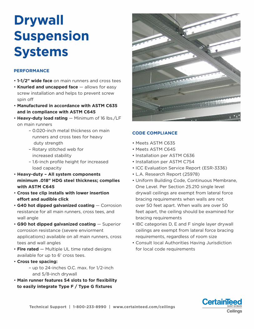
CODE COMPLIANCE
• Meets ASTM C635• Meets ASTM C645• Installation per ASTM C636• Installation per ASTM C754• ICC Evaluation Service Report (ESR-3336)• L.A. Research Report (25978)• Uniform Building Code, Continuous Membrane,
One Level. Per Section 25.210 single level drywall ceilings are exempt from lateral force bracing requirements when walls are not over 50 feet apart. When walls are over 50 feet apart, the ceiling should be examined for bracing requirements
• IBC categories D, E and F single layer drywall ceilings are exempt from lateral force bracing requirements, regardless of room size
• Consult local Authorities Having Jurisdiction for local code requirements
PERFORMANCE
• 1-1/2" wide face on main runners and cross tees• Knurled and uncapped face — allows for easy
screw installation and helps to prevent screw spin off
• Manufactured in accordance with ASTM C635 and in compliance with ASTM C645
• Heavy-duty load rating — Minimum of 16 lbs./LF on main runners
– 0.020-inch metal thickness on main runners and cross tees for heavy duty strength
– Rotary stitched web for increased stability
– 1.6-inch profile height for increased load capacity
• Heavy-duty – All system components minimum .018" HDG steel thickness; complies with ASTM C645
• Cross tee clip installs with lower insertion effort and audible click
• G40 hot dipped galvanized coating — Corrosion resistance for all main runners, cross tees, and wall angle
• G90 hot dipped galvanized coating — Superior corrosion resistance (severe enviorment applications) available on all main runners, cross tees and wall angles
• Fire rated — Multiple UL time rated designs available for up to 6' cross tees.
• Cross tee spacing: – up to 24-inches O.C. max. for 1/2-inch
and 5/8-inch drywall• Main runner features 54 slots to for flexibility
to easily integrate Type F / Type G fixtures
Technical Support | 1-800-233-8990 | www.certainteed.com/ceilings
Drywall Suspension Systems
p5
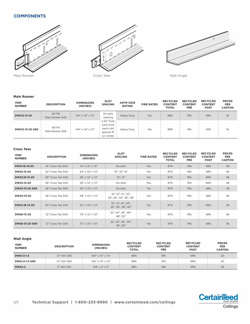
COMPONENTS
Main Runner
Cross Tees
Wall Angle
ITEM NUMBER DESCRIPTION DIMENSIONS
(INCHES)
SLOTSPACING ASTM C635
RATING FIRE RATEDRECYCLEDCONTENT
TOTAL
RECYCLEDCONTENT
PRE
RECYCLEDCONTENT
POST
PIECESPER
CARTON
DWS12-13-20HD FR
Main Runner G40144" x 1.6" x 1.5"
54 slots starting
2.25" from each end; each slot spaced 8" on center
Heavy Duty Yes 88% 19% 69% 16
DWS12-13-20 G90HD FR
Main Runner G90144" x 1.6" x 1.5" Heavy Duty Yes 88% 19% 69% 16
ITEM NUMBER DESCRIPTION DIMENSIONS
(INCHES)
SLOTSPACING FIRE RATED
RECYCLEDCONTENT
TOTAL
RECYCLEDCONTENT
PRE
RECYCLEDCONTENT
POST
PIECESPER
CARTON
DWS1.16-13-20 14" Cross Tee G40 14" x 1.6" x 1.5" No slots Yes 87% 19% 68% 48
DWS2-13-20 24" Cross Tee G40 24" x 1.6" x 1.5" 10", 12", 14" Yes 87% 19% 68% 48
DWS2.16-13-20 26" Cross Tee G40 26" x 1.6" x 1.5" 12", 14" Yes 87% 19% 68% 48
DWS3-13-20 36" Cross Tee G40 36" x 1.6" x 1.5" No slots Yes 87% 19% 68% 48
DWS3-13-20 G90 36" Cross Tee G90 36" x 1.6" x 1.5" No slots Yes 87% 19% 68% 48
DWS4-13-20 48" Cross Tee G40 48" x 1.6" x 1.5"10", 12", 14", 22",
24", 26", 34", 36", 38"Yes 87% 19% 68% 48
DWS4.16-13-20 50" Cross Tee G40 50" x 1.6" x 1.5"10", 12", 14", 24",
26", 36", 38", 40"Yes 87% 19% 68% 48
DWS6-13-20 72" Cross Tee G40 72" x 1.6" x 1.5"22", 24", 26", 46",
48", 50"Yes 87% 19% 68% 36
DWS6-13-20 G90 72" Cross Tee G90 72" x 1.6" x 1.5"22", 24", 26", 46",
48", 50"Yes 87% 19% 68% 36
ITEM NUMBER DESCRIPTION DIMENSIONS
(INCHES)
RECYCLEDCONTENT
TOTAL
RECYCLEDCONTENT
PRE
RECYCLEDCONTENT
POST
PIECESPER
CARTON
DWA1.5-1.5 1.5" WA G40 144" x 1.5" x 1.5" 88% 19% 69% 20
DWA1.5-1.5 G90 1.5" WA G90 144" x 1.5" x 1.5" 88% 19% 69% 20
DWA2-2 2" WA G40 144" x 2" x 2" 88% 19% 69% 36
Main Runner Cross Tees Wall Angle
Technical Support | 1-800-233-8990 | www.certainteed.com/ceilings
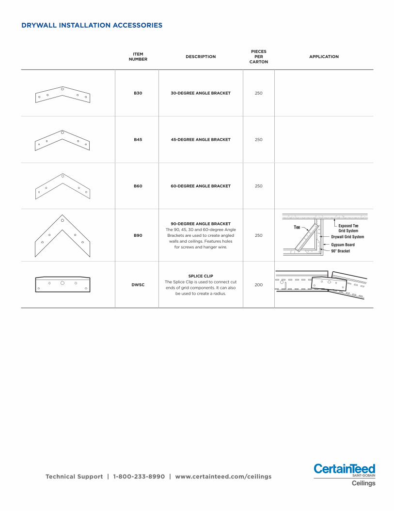
DRYWALL INSTALLATION ACCESSORIES
ITEM NUMBER DESCRIPTION
PIECESPER
CARTONAPPLICATION
B30 30-DEGREE ANGLE BRACKET 250
B45 45-DEGREE ANGLE BRACKET 250
B60 60-DEGREE ANGLE BRACKET 250
B90
90-DEGREE ANGLE BRACKETThe 90, 45, 30 and 60-degree AngleBrackets are used to create angled walls and ceilings. Features holes
for screws and hanger wire.
250
DWSC
SPLICE CLIPThe Splice Clip is used to connect cutends of grid components. It can also
be used to create a radius.
200
Tee Exposed TeeGrid System
Drywall Grid System
Gypsum Board
90° Bracket
Technical Support | 1-800-233-8990 | www.certainteed.com/ceilings
p7
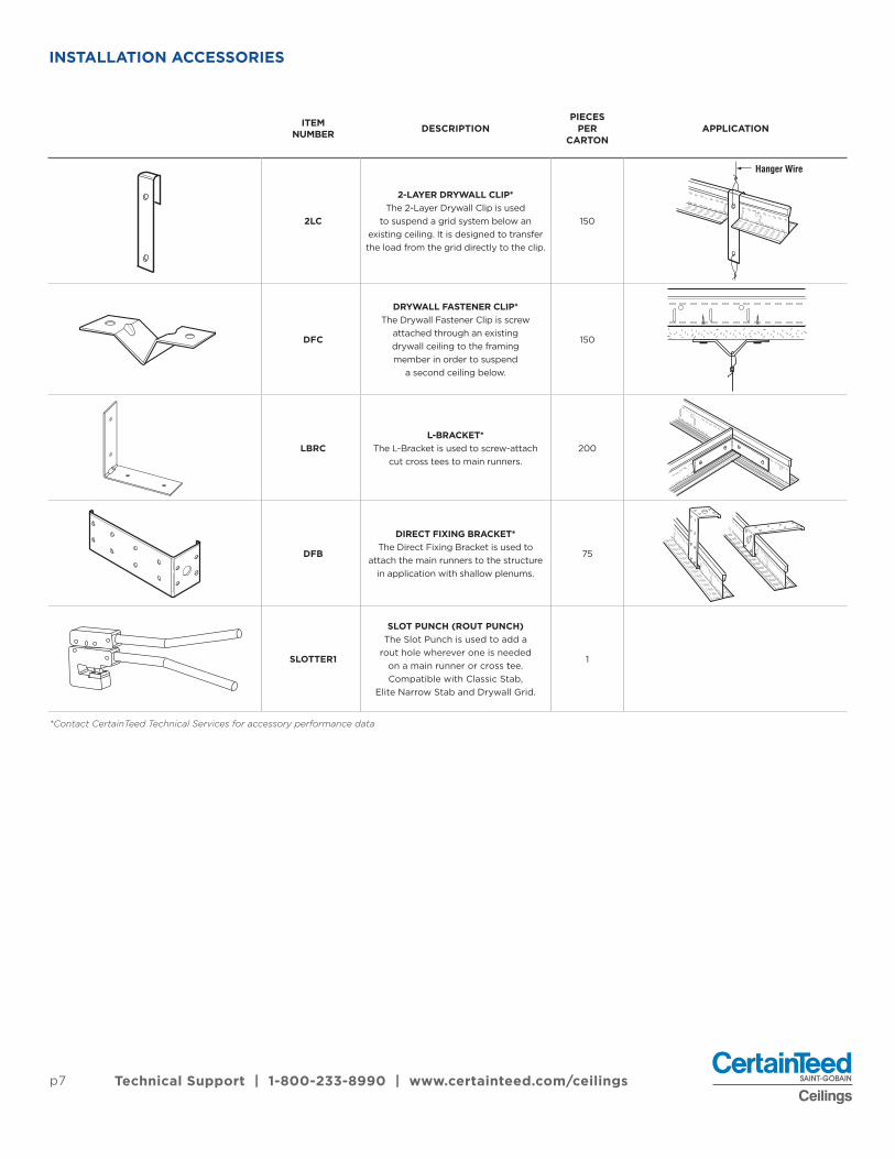
INSTALLATION ACCESSORIES
ITEM NUMBER DESCRIPTION
PIECESPER
CARTONAPPLICATION
2LC
2-LAYER DRYWALL CLIP*The 2-Layer Drywall Clip is used
to suspend a grid system below anexisting ceiling. It is designed to transferthe load from the grid directly to the clip.
150
DFC
DRYWALL FASTENER CLIP*The Drywall Fastener Clip is screw
attached through an existing drywall ceiling to the framing member in order to suspend
a second ceiling below.
150
LBRCL-BRACKET*
The L-Bracket is used to screw-attachcut cross tees to main runners.
200
DFB
DIRECT FIXING BRACKET*The Direct Fixing Bracket is used to
attach the main runners to the structurein application with shallow plenums.
75
SLOTTER1
SLOT PUNCH (ROUT PUNCH)The Slot Punch is used to add a
rout hole wherever one is needed on a main runner or cross tee. Compatible with Classic Stab,
Elite Narrow Stab and Drywall Grid.
1
Hanger Wire
Technical Support | 1-800-233-8990 | www.certainteed.com/ceilings
*Contact CertainTeed Technical Services for accessory performance data
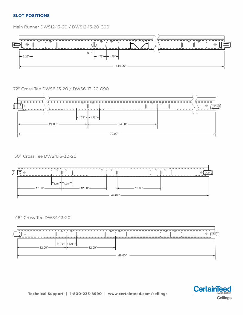
SLOT POSITIONS
Main Runner DWS12-13-20 / DWS12-13-20 G90
72" Cross Tee DWS6-13-20 / DWS6-13-20 G90
Technical Support | 1-800-233-8990 | www.certainteed.com/ceilings
72.00”
24.00”
1.75” 1.75”
24.00”
A
144.00”
2.25” 1.75” 1.75”
50" Cross Tee DWS4.16-30-20
49.64”
1.75”1.75”
12.00” 12.00”12.00”
48" Cross Tee DWS4-13-20
48.00”
1.75” 1.75”12.00” 12.00”

p9
SLOT POSITIONS
36" Cross Tee DWS3-13-20 / DWS3-13-20 G90
26" Cross Tee DWS2. 16-13-20
Technical Support | 1-800-233-8990 | www.certainteed.com/ceilings
36.00”
1.75”12.00”
26.00”
24" Cross Tee DWS2-13-20
1.75” 1.75”
12.00”
24.00”
14" Cross Tee DWS1.16-13-20
14.00”

Type F Fixtures
1. Install from below the grid2. Fixture has integral flange (or separate
flange kit) to finish the drywall board3. Fixture rests on bulb of grid and/or is
suspended from flange kit4. Fixture is level with drywall5. Requires actual 48-inch opening
Type G Fixtures
1. Install from above the grid2. Fixture trim is required for finishing drywall3. Fixture rests on flange of grid4. Fixture is recessed the thickness
of the drywall5. Requires nominal 48-inch opening
TYPE F VS. TYPE G FIXTURES
CertainTeed Ceilings Drywall Suspension System main runners provide slots 8" on center. Each slot has two additional offset slots- each is 1-3/4" from the center slot. These additional offset slots allow for integration with Type F fixtures. Use the center slot for typical cross tee installation.
LIGHTING INTEGRATION – OFFSET SLOTS
Technical Support | 1-800-233-8990 | www.certainteed.com/ceilings
p11
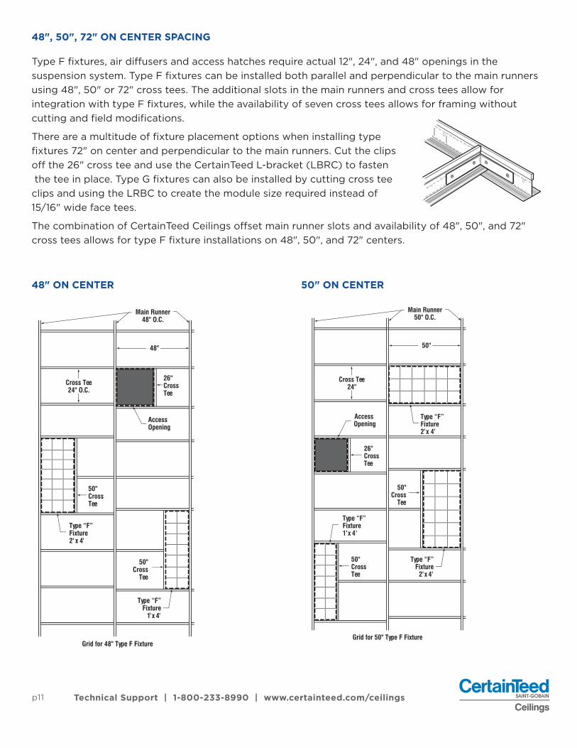
48", 50", 72" ON CENTER SPACING
48" ON CENTER 50" ON CENTER
Type F fixtures, air diffusers and access hatches require actual 12", 24", and 48" openings in the suspension system. Type F fixtures can be installed both parallel and perpendicular to the main runners using 48", 50" or 72" cross tees. The additional slots in the main runners and cross tees allow for integration with type F fixtures, while the availability of seven cross tees allows for framing without cutting and field modifications.
There are a multitude of fixture placement options when installing type fixtures 72" on center and perpendicular to the main runners. Cut the clips off the 26" cross tee and use the CertainTeed L-bracket (LBRC) to fasten the tee in place. Type G fixtures can also be installed by cutting cross tee clips and using the LRBC to create the module size required instead of 15/16" wide face tees.
The combination of CertainTeed Ceilings offset main runner slots and availability of 48", 50", and 72" cross tees allows for type F fixture installations on 48", 50", and 72" centers.
AccessOpening
Type “F”Fixture2' x 4'
Type “F”Fixture
1'x 4'
50"Cross
Tee
Main Runner48" O.C.
26"CrossTee
50"CrossTee
Cross Tee24" O.C.
Grid for 48" Type F Fixture
48"
Access Opening
Type “F”Fixture2'x 4'
Type “F”Fixture
2'x 4'
Type “F”Fixture1'x 4'
Main Runner50" O.C.
26"CrossTee
50"
Cross Tee24"
50"CrossTee
Grid for 50" Type F Fixture
50"Cross
Tee
Technical Support | 1-800-233-8990 | www.certainteed.com/ceilings

UL FIRE RESISTIVE ASSEMBLIES (DRYWALL SUSPENSION SYSTEMS ONLY)
Technical Support | 1-800-233-8990 | www.certainteed.com/ceilings
TYPE OF CONSTRUCTION
MAXIMUM TIME RATING
(HRS)
UL DESIGN NUMBER
CONCRETE THICKNESS (INCHES)
NUMBER OF DRYWALL LAYERS
MINIMUMDRYWALL
THICKNESS
MAXIMUM FIXTURE
PENETRATION (FT2 / 100 FT2)
MAXIMUM DUCT
PENETRATION (IN2 / 100 FT2)
DRYWALL GRID
SYSTEM
Concrete on metal lath or corrugated steel deck, steel joists
2 D501 2-1/2" 1 1/2" N/A N/A CertainTeed DWS1
Concrete on metal lath or corrugated steel deck, steel joists
2 D502 2-1/2" 1 1/2" 24 144 CertainTeed DWS1
Concrete on metal lath or corrugated steel deck, steel joists
2 D503 2-1/2" 1 1/2" One 6" diameterfixture per 25 ft2 N/A CertainTeed DWS1
Concrete on metal lath or corrugated steel deck, steel joists
2 G041 2-1/2" 1 1/2" 15.3 54 CertainTeed DWS1
Concrete on metal lath or corrugated steel deck, steel joists
1 G041 2-1/2" 1 1/2" 15.3 54CertainTeed DWS
(max 72" cross tee)
Concrete on metal lath or corrugated steel deck, steel joists
2 G523 2-1/2" 1 1/2" 24 144 CertainTeed DWS1
Concrete on metal lath or corrugated steel deck, steel joists
2 G524 2-1/2" 1 1/2" One fixture per100 ft2 144 CertainTeed DWS1
Concrete on metal lath or corrugated steel deck, steel joists
2 G526 2-1/2" 1 1/2" 24 56.5 CertainTeed DWS1
Concrete on metal lath or corrugated steel deck, steel joists
2 G527 2-1/2" 1 1/2" N/A N/A CertainTeed DWS1
Concrete on metal lath or corrugated steel deck, steel joists
1-1/2 G528 2-1/2" 1 1/2" N/A N/A CertainTeed DWS1
Concrete on metal lath or corrugated steel deck, steel joists
2 G529 2-1/2" 1 1/2" 24 57 CertainTeed DWS1
Concrete on metal lath or corrugated steel deck, steel joists
2 G553 2-1/2" 1 1/2" N/A N/A CertainTeed DWS1
Wood Deck 1 L502 — 1 1/2" N/A 99 CertainTeed DWS1
Wood Deck 1 L508 — 1 1/2" N/A 99 CertainTeed DWS1
Wood Deck 1 L513 — 1 1/2" N/A 99 CertainTeed DWS1
Wood Deck 1 L515 — 1 1/2" N/A 99 CertainTeed DWS1
Wood Deck 1 L525 — 1 1/2" 24 113 CertainTeed DWS1
Wood Deck 1 L526 — 1 1/2" 24 100 CertainTeed DWS1
Wood Deck 1 L529 — 1 1/2" 24 113 CertainTeed DWS1
Fire Ratings specified in this section pertain to UL Classifications which are based on standard test method ANSI/UL263, ASTM E119, UBC 7-1, NFPA 251, CAN/ULC - S101M
Floor / Ceiling Drywall Assemblies
1. Maximum 50" cross tee

p13 Technical Support | 1-800-233-8990 | www.certainteed.com/ceilings
1. Maximum 50" cross teeThe information contained in this table is intended only to be used as a guide. For detailed time-rated assembly information,refer to the latest Underwriters Laboratories Inc. Fire Resistance Directory (ul.com).
TYPE OF CONSTRUCTION
MAXIMUM TIME RATING
(HRS)
UL DESIGN NUMBER
CONCRETE THICKNESS (INCHES)
NUMBER OF DRYWALL LAYERS
MINIMUMDRYWALL
THICKNESS
MAXIMUM FIXTURE
PENETRATION (FT2 / 100 FT2)
MAXIMUM DUCT
PENETRATION (IN2 / 100 FT2)
DRYWALL GRID
SYSTEM
BUR, modified orsingle-ply over steeldeck, steel joists
1-1/2 P506 — 1 5/8" 24 113 CertainTeed DWS1
BUR, modified orsingle-ply over steeldeck, steel joists
1 P508 — 1 5/8" 24 144 CertainTeed DWS1
BUR, modified orsingle-ply over steeldeck, steel joists
1 P509 — 1 5/8" 24 144 CertainTeed DWS1
BUR, modified orsingle-ply over steeldeck, steel joists
1-1/2 P510 — 1 5/8" 24 113 CertainTeed DWS1
BUR, modified orsingle-ply over steeldeck, steel joists
1-1/2 P513 — 1 5/8" 24 144 CertainTeed DWS1
BUR, modified orsingle-ply over steeldeck, steel joists
2 P514 — 1 5/8" 24 255 CertainTeed DWS1
BUR, modified orsingle-ply over steeldeck, steel joists
2 P560 — 1 5/8" 15.3 54 CertainTeed DWS1
Roof / Ceiling Drywall Assemblies
UL
TYPE OF CONSTRUCTION
MAXIMUM TIME RATING
(HRS)
UL DESIGN NUMBER
CONCRETE THICKNESS (INCHES)
NUMBER OF DRYWALL LAYERS
MINIMUMDRYWALL
THICKNESS
MAXIMUM FIXTURE
PENETRATION (FT2 / 100 FT2)
MAXIMUM DUCT
PENETRATION (IN2 / 100 FT2)
DRYWALL GRID
SYSTEM
Concrete on metal lath or corrugated steel deck, steel joists
2 G021 2.5 1 1/2" 15.3 54CertainTeed DWS
(max. 50" cross tee)
Concrete on metal lath or corrugated steel deck, steel joists
1 G021 2.5 1 1/2" 15.3 54CertainTeed DWS
(max. 72" cross tee)
Floor / Ceiling Drywall Assemblies
Technical Support | 1-800-233-8990 | www.certainteed.com/ceilings
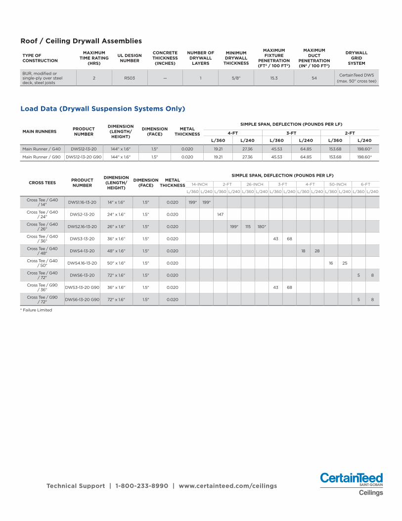
MAIN RUNNERS PRODUCT NUMBER
DIMENSION (LENGTH/HEIGHT)
DIMENSION (FACE)
METAL THICKNESS
SIMPLE SPAN, DEFLECTION (POUNDS PER LF)
4-FT 3-FT 2-FT
L/360 L/240 L/360 L/240 L/360 L/240
Main Runner / G40 DWS12-13-20 144" x 1.6" 1.5" 0.020 19.21 27.36 45.53 64.85 153.68 198.60*
Main Runner / G90 DWS12-13-20 G90 144" x 1.6" 1.5" 0.020 19.21 27.36 45.53 64.85 153.68 198.60*
CROSS TEES PRODUCT NUMBER
DIMENSION (LENGTH/HEIGHT)
DIMENSION (FACE)
METAL THICKNESS
SIMPLE SPAN, DEFLECTION (POUNDS PER LF)
14-INCH 2-FT 26-INCH 3-FT 4-FT 50-INCH 6-FT
L/360 L/240 L/360 L/240 L/360 L/240 L/360 L/240 L/360 L/240 L/360 L/240 L/360 L/240
Cross Tee / G40 / 14" DWS1.16-13-20 14" x 1.6" 1.5" 0.020 199* 199*
Cross Tee / G40 / 24" DWS2-13-20 24" x 1.6” 1.5” 0.020 147
Cross Tee / G40 / 26" DWS2.16-13-20 26" x 1.6" 1.5" 0.020 199* 115 180*
Cross Tee / G40 / 36" DWS3-13-20 36" x 1.6" 1.5" 0.020 43 68
Cross Tee / G40 / 48" DWS4-13-20 48" x 1.6" 1.5" 0.020 18 28
Cross Tee / G40 / 50" DWS4.16-13-20 50" x 1.6" 1.5" 0.020 16 25
Cross Tee / G40 / 72" DWS6-13-20 72" x 1.6" 1.5" 0.020 5 8
Cross Tee / G90 / 36" DWS3-13-20 G90 36" x 1.6" 1.5" 0.020 43 68
Cross Tee / G90 / 72" DWS6-13-20 G90 72" x 1.6" 1.5" 0.020 5 8
* Failure Limited
TYPE OF CONSTRUCTION
MAXIMUM TIME RATING
(HRS)
UL DESIGN NUMBER
CONCRETE THICKNESS (INCHES)
NUMBER OF DRYWALL LAYERS
MINIMUMDRYWALL
THICKNESS
MAXIMUM FIXTURE
PENETRATION (FT2 / 100 FT2)
MAXIMUM DUCT
PENETRATION (IN2 / 100 FT2)
DRYWALL GRID
SYSTEM
BUR, modified or single-ply over steel deck, steel joists
2 R503 — 1 5/8" 15.3 54CertainTeed DWS
(max. 50" cross tee)
Roof / Ceiling Drywall Assemblies
Load Data (Drywall Suspension Systems Only)
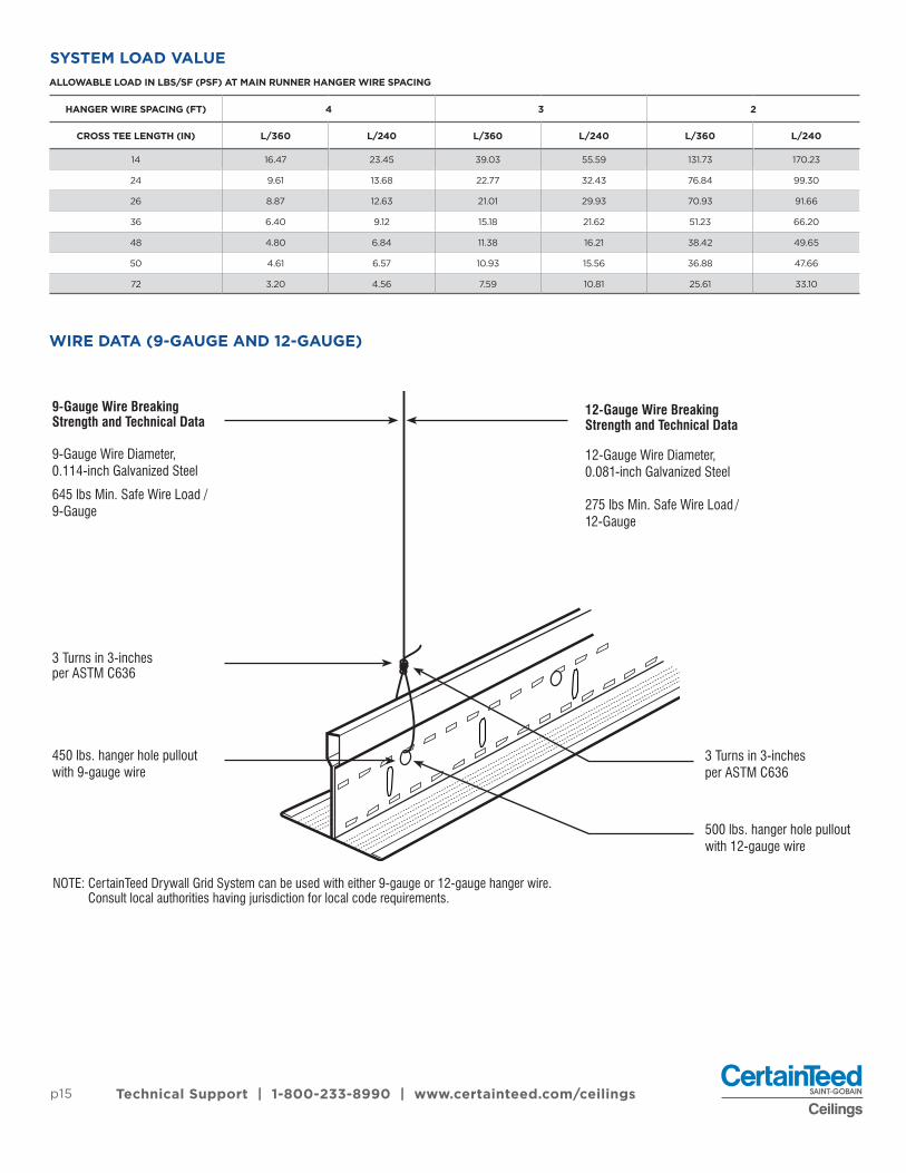
9-Gauge Wire Breaking Strength and Technical Data
12-Gauge Wire Breaking Strength and Technical Data
9-Gauge Wire Diameter, 0.114-inch Galvanized Steel
645 lbs Min. Safe Wire Load / 9-Gauge
12-Gauge Wire Diameter, 0.081-inch Galvanized Steel
275 lbs Min. Safe Wire Load / 12-Gauge
3 Turns in 3-inches per ASTM C636
450 lbs. hanger hole pullout with 9-gauge wire
3 Turns in 3-inches per ASTM C636
500 lbs. hanger hole pullout with 12-gauge wire
NOTE: CertainTeed Drywall Grid System can be used with either 9-gauge or 12-gauge hanger wire. Consult local authorities having jurisdiction for local code requirements.
WIRE DATA (9-GAUGE AND 12-GAUGE)
p15 Technical Support | 1-800-233-8990 | www.certainteed.com/ceilings
ALLOWABLE LOAD IN LBS/SF (PSF) AT MAIN RUNNER HANGER WIRE SPACING
HANGER WIRE SPACING (FT) 4 3 2
CROSS TEE LENGTH (IN) L/360 L/240 L/360 L/240 L/360 L/240
14 16.47 23.45 39.03 55.59 131.73 170.23
24 9.61 13.68 22.77 32.43 76.84 99.30
26 8.87 12.63 21.01 29.93 70.93 91.66
36 6.40 9.12 15.18 21.62 51.23 66.20
48 4.80 6.84 11.38 16.21 38.42 49.65
50 4.61 6.57 10.93 15.56 36.88 47.66
72 3.20 4.56 7.59 10.81 25.61 33.10
SYSTEM LOAD VALUE
Technical Support | 1-800-233-8990 | www.certainteed.com/ceilings
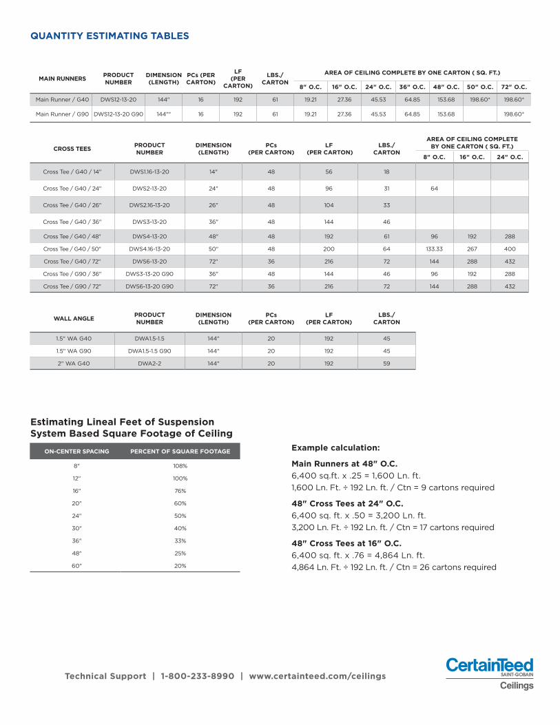
MAIN RUNNERS PRODUCT NUMBER
DIMENSION (LENGTH)
PCs (PER CARTON)
LF (PER
CARTON)
LBS./ CARTON
AREA OF CEILING COMPLETE BY ONE CARTON ( SQ. FT.)
8" O.C. 16" O.C. 24" O.C. 36" O.C. 48" O.C. 50" O.C. 72" O.C.
Main Runner / G40 DWS12-13-20 144" 16 192 61 19.21 27.36 45.53 64.85 153.68 198.60* 198.60*
Main Runner / G90 DWS12-13-20 G90 144"" 16 192 61 19.21 27.36 45.53 64.85 153.68 198.60*
CROSS TEES PRODUCT NUMBER
DIMENSION (LENGTH)
PCs (PER CARTON)
LF (PER CARTON)
LBS./ CARTON
AREA OF CEILING COMPLETE BY ONE CARTON ( SQ. FT.)
8" O.C. 16" O.C. 24" O.C.
Cross Tee / G40 / 14" DWS1.16-13-20 14" 48 56 18
Cross Tee / G40 / 24" DWS2-13-20 24" 48 96 31 64
Cross Tee / G40 / 26" DWS2.16-13-20 26" 48 104 33
Cross Tee / G40 / 36" DWS3-13-20 36" 48 144 46
Cross Tee / G40 / 48" DWS4-13-20 48" 48 192 61 96 192 288
Cross Tee / G40 / 50" DWS4.16-13-20 50" 48 200 64 133.33 267 400
Cross Tee / G40 / 72" DWS6-13-20 72" 36 216 72 144 288 432
Cross Tee / G90 / 36" DWS3-13-20 G90 36" 48 144 46 96 192 288
Cross Tee / G90 / 72" DWS6-13-20 G90 72" 36 216 72 144 288 432
WALL ANGLE PRODUCT NUMBER
DIMENSION (LENGTH)
PCs (PER CARTON)
LF (PER CARTON)
LBS./ CARTON
1.5" WA G40 DWA1.5-1.5 144" 20 192 45
1.5" WA G90 DWA1.5-1.5 G90 144" 20 192 45
2" WA G40 DWA2-2 144" 20 192 59
ON-CENTER SPACING PERCENT OF SQUARE FOOTAGE
8" 108%
12" 100%
16" 76%
20" 60%
24" 50%
30" 40%
36" 33%
48" 25%
60" 20%
QUANTITY ESTIMATING TABLES
Example calculation:
Main Runners at 48" O.C.6,400 sq.ft. x .25 = 1,600 Ln. ft.1,600 Ln. Ft. ÷ 192 Ln. ft. / Ctn = 9 cartons required
48" Cross Tees at 24" O.C.6,400 sq. ft. x .50 = 3,200 Ln. ft.3,200 Ln. Ft. ÷ 192 Ln. ft. / Ctn = 17 cartons required
48" Cross Tees at 16" O.C.6,400 sq. ft. x .76 = 4,864 Ln. ft.4,864 Ln. Ft. ÷ 192 Ln. ft. / Ctn = 26 cartons required
Estimating Lineal Feet of Suspension System Based Square Footage of Ceiling

Technical Support | 1-800-233-8990 | www.certainteed.com/ceilingsp17
QuickSpan™ Locking Channel• 1-9/16-inches wide bottom flange• 0.020-inch metal thickness allows for superior
rigidity and maximum screw retention• Tees quickly twist into place for fast installation• Knurled pattern on back and bottom of flange
for easy screw insertion• No need for screw-attachment of tees• Integral locking tabs spaced 8-inches O.C.
allows 8", 16", 24" tee spacing• G40 hot dipped galvanized steel for
excellent corrosion resistance
QuickSpan™ Cross Tees• 1-1/2-inches wide face with knurled
face for easy screw installation and no screw spin off
• Unsupported spans – max. 12-ft for 1/2-inch drywall and 11-ft 3" for 5/8-inch drywall
• Heavy duty material – 0.020-inches metal thickness for maximum rigidity and screw grip
• Double-stitched web for added strength• Sizes – standard and custom lengths available
• Meets ASTM C635• Meets ASTM C645• Installation per ASTM C636• Installation per ASTM C754• ICC Evaluation Service Report (ESR 3941)• Uniform Building Code, Continuous Membrane,
One Level. Per Section 25.210 single-level drywall ceilings are exempt from lateral force bracing requirements when walls are not over 50-feet apart. When walls are over 50-feet apart, the ceiling should be examined for bracing requirements.
• IBC categories D, E and F single layer drywall ceilings are exempt from lateral force bracing requirements, regardless of room size
• Consult local authorities having jurisdiction for local code requirements
PERFORMANCE
CODE COMPLIANCE
QuickSpan™ Locking Drywall Suspension System
Technical Support | 1-800-233-8990 | www.certainteed.com/ceilings
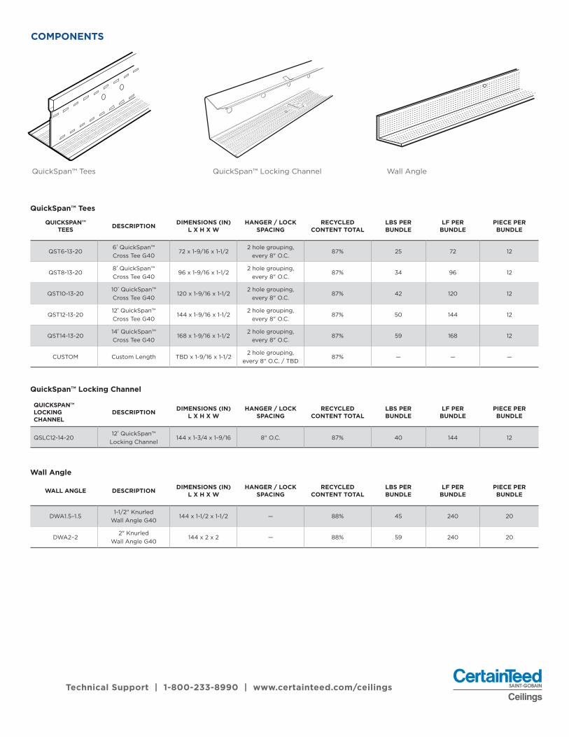
COMPONENTS
QUICKSPAN™ TEES DESCRIPTION DIMENSIONS (IN)
L X H X WHANGER / LOCK
SPACINGRECYCLED
CONTENT TOTALLBS PER BUNDLE
LF PER BUNDLE
PIECE PER BUNDLE
QST6-13-206' QuickSpan™ Cross Tee G40
72 x 1-9/16 x 1-1/22 hole grouping,
every 8" O.C.87% 25 72 12
QST8-13-208' QuickSpan™ Cross Tee G40
96 x 1-9/16 x 1-1/22 hole grouping,
every 8" O.C.87% 34 96 12
QST10-13-2010' QuickSpan™ Cross Tee G40
120 x 1-9/16 x 1-1/22 hole grouping,
every 8" O.C.87% 42 120 12
QST12-13-2012' QuickSpan™ Cross Tee G40
144 x 1-9/16 x 1-1/22 hole grouping,
every 8" O.C.87% 50 144 12
QST14-13-2014' QuickSpan™ Cross Tee G40
168 x 1-9/16 x 1-1/22 hole grouping,
every 8" O.C.87% 59 168 12
CUSTOM Custom Length TBD x 1-9/16 x 1-1/22 hole grouping,
every 8" O.C. / TBD87% — — —
QUICKSPAN™ LOCKING CHANNEL
DESCRIPTION DIMENSIONS (IN) L X H X W
HANGER / LOCK SPACING
RECYCLED CONTENT TOTAL
LBS PER BUNDLE
LF PER BUNDLE
PIECE PER BUNDLE
QSLC12-14-2012' QuickSpan™
Locking Channel144 x 1-3/4 x 1-9/16 8" O.C. 87% 40 144 12
WALL ANGLE DESCRIPTION DIMENSIONS (IN) L X H X W
HANGER / LOCK SPACING
RECYCLED CONTENT TOTAL
LBS PER BUNDLE
LF PER BUNDLE
PIECE PER BUNDLE
DWA1.5–1.51-1/2" Knurled
Wall Angle G40144 x 1-1/2 x 1-1/2 — 88% 45 240 20
DWA2–22" Knurled
Wall Angle G40144 x 2 x 2 — 88% 59 240 20
QuickSpan™ Tees
QuickSpan™ Locking Channel
Wall Angle
QuickSpan™ Tees QuickSpan™ Locking Channel Wall Angle

Technical Support | 1-800-233-8990 | www.certainteed.com/ceilingsp19
Locking Channel QSLC12-14-20
Spanning Tees QST6-13-20 / QST8-13-20 / QST10-13-20 / QST12-13-20 / QST14-13-20
Spacing (side view)
Spacing (side view)
Profile (end view)
Profile (end view)
144"
8" O.C.
1/4"
13/32"
1-19/32"
1-1/2"
1-3/4"
1-9/16"
1-1/2"
1/4"
Lengths Available: 72" / 96" / 120" / 144" / 168"
PROFILE AND SPACING
2 holes 8" o.c.
Technical Support | 1-800-233-8990 | www.certainteed.com/ceilings
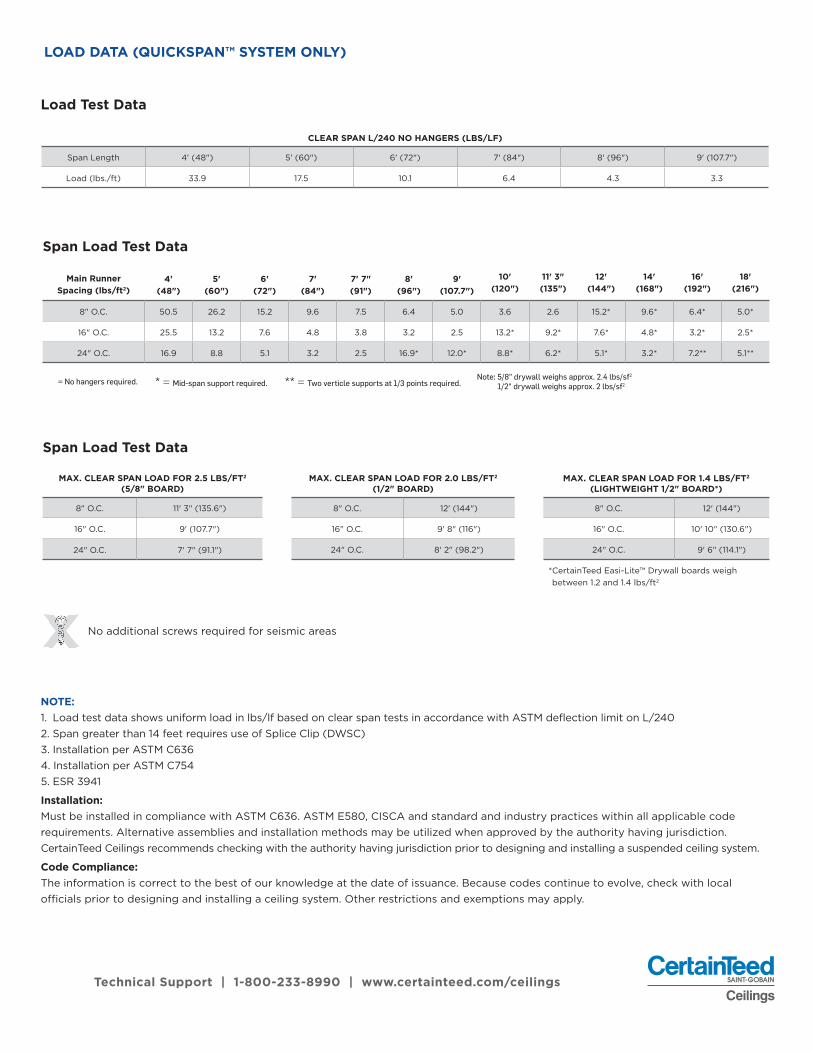
LOAD DATA (QUICKSPAN™ SYSTEM ONLY)
NOTE: 1. Load test data shows uniform load in lbs/lf based on clear span tests in accordance with ASTM deflection limit on L/2402. Span greater than 14 feet requires use of Splice Clip (DWSC)3. Installation per ASTM C6364. Installation per ASTM C7545. ESR 3941
Installation:Must be installed in compliance with ASTM C636. ASTM E580, CISCA and standard and industry practices within all applicable code requirements. Alternative assemblies and installation methods may be utilized when approved by the authority having jurisdiction. CertainTeed Ceilings recommends checking with the authority having jurisdiction prior to designing and installing a suspended ceiling system.
Code Compliance:The information is correct to the best of our knowledge at the date of issuance. Because codes continue to evolve, check with local officials prior to designing and installing a ceiling system. Other restrictions and exemptions may apply.
No additional screws required for seismic areasXX
Span Load Test Data
MAX. CLEAR SPAN LOAD FOR 2.5 LBS/FT2 (5/8" BOARD)
8" O.C. 11' 3" (135.6")
16" O.C. 9' (107.7")
24" O.C. 7' 7" (91.1")
MAX. CLEAR SPAN LOAD FOR 2.0 LBS/FT2 (1/2" BOARD)
8" O.C. 12' (144")
16" O.C. 9' 8" (116")
24" O.C. 8' 2" (98.2")
MAX. CLEAR SPAN LOAD FOR 1.4 LBS/FT2 (LIGHTWEIGHT 1/2" BOARD*)
8" O.C. 12' (144")
16" O.C. 10' 10" (130.6")
24" O.C. 9' 6" (114.1")
* CertainTeed Easi-Lite™ Drywall boards weigh between 1.2 and 1.4 lbs/ft2
Span Load Test Data
Main RunnerSpacing (lbs/ft2)
4' (48")
5' (60")
6' (72")
7' (84")
7' 7" (91")
8' (96")
9'(107.7")
10' (120")
11' 3" (135")
12' (144")
14' (168")
16' (192")
18' (216")
8" O.C. 50.5 26.2 15.2 9.6 7.5 6.4 5.0 3.6 2.6 15.2* 9.6* 6.4* 5.0*
16" O.C. 25.5 13.2 7.6 4.8 3.8 3.2 2.5 13.2* 9.2* 7.6* 4.8* 3.2* 2.5*
24" O.C. 16.9 8.8 5.1 3.2 2.5 16.9* 12.0* 8.8* 6.2* 5.1* 3.2* 7.2** 5.1**
= No hangers required. * = Mid-span support required. ** = Two verticle supports at 1/3 points required.Note: 5/8" drywall weighs approx. 2.4 lbs/sf2
1/2" drywall weighs approx. 2 lbs/sf2
Load Test Data
CLEAR SPAN L/240 NO HANGERS (LBS/LF)
Span Length 4' (48") 5' (60") 6' (72") 7' (84") 8' (96") 9' (107.7")
Load (lbs./ft) 33.9 17.5 10.1 6.4 4.3 3.3

Technical Support | 1-800-233-8990 | www.certainteed.com/ceilingsp21
INSTALLATION METHOD AND INSTRUCTIONS FOR QUICKSPAN™
Installing the QuickSpan™ Locking Channel1. Establish the ceiling elevation factoring in drywall board thickness to be used.
2. Place the bottom of the QuickSpan Locking Channel (QSLC) at the appropriate level.
3. Decide upon a location for your first QuickSpan™ tee. The locking tabs on the QSLC are spaced every 8-inches on center and can be cut to the desired spacing from the abutting wall.
a. To cut the QSLC, choose the desired slot, measure from the wall and cut through the top and bottom flanges first. Finish by folding the scored piece back and cut through the rest of the channel.
4. Screw-attach the QSLC into existing wall framing system. (Use number 8, 1.25-inch, steel framing, self-tapping screws complying with SAE J78 and ASTM C1002).
5. On short walls where locking channel and/or tees are NOT needed; drywall wall angle can be used.
a. 1-1/2-inches (DWA1.5-1.5) or 2-inches (DWA2-2) wide pieces available
Installing the QuickSpan™ Cross Tees1. Measure across the hallway from inside of QSLC to inside of QSLC. Find a measurement that provides
a 1/4-inch to 1/8-inch gap at both ends.
a. For example, if the walls are 8-feet (96-inches) apart, you will want to cut your tees to 95-3/4 inches to allow the proper gap between the wall channel and tee.
2. Start at one end of the ceiling and place a QuickSpan tee into the QSLC on both sides. Make sure that the tee is lying at an angle and moves freely in the channel.
a. Place all of the tees into the channel or do one at a time, it does not matter to the system.
3. Find the next slot on the QSLC that corresponds to the chosen spacing pattern and place the bulb (top) of the tee into the upper locator slot in the V of the QSLC.
4. Rotate the bottom of the tee into position. You will hear an audible click as the tee engages in the bottom locking tab of the QSLC. This will tell you that the tee is in place and locked.
a. Screw-attachment is NOT required, but a pilot hole is provided in the event that you find it necessary to apply a screw.
5. Proceed to the other end of the QuickSpan tee and follow the same process. Notice that QuickSpan tee access to the locking tabs is on alternate sides in the QSLC. The system is designed this way to provide added rotational strength.
6. Note that there are hanger hole groupings provided every 8 inches across the tees. This allows the installer to provide a hanger where an excessive load is going to be placed on the system.
7. To create an opening for a device: use a cut QuickSpan tee to frame the opening within the QuickSpan system. a. Standard accessories are available to attach cross tees for device openings (L-Bracket LBRC,
Splice Clip DWSP and Direct Fixing Bracket DFB)
Step-by-step illustrations - Assembly of Spanning Tee and Locking Channel

Technical Support | 1-800-233-8990 | www.certainteed.com/ceilings
INSTALLATION METHOD AND INSTRUCTIONS FOR QUICKSPAN™
Installing Gypsum Board to the QuickSpan™ SystemIn non-fire rated ceiling assemblies, it is the contractor's discretion as to the orientation of the gypsum board, whether it is applied parallel or perpendicular to the supporting structure. The long, tapered edges of the board should be installed parallel to the QuickSpan tees. Some gypsum product manufacturers will require their product to be installed with the long, tapered edges perpendicular to ceiling framing members. Refer to their product data pages for specific information concerning product installation.
Maximum 5/8-inch thick gypsum board must be installed and fastened to the QuickSpan Locking Drywall System in accordance with IBC Section2508, ASTM C840, and Gypsum Association GA-216.
Change in Direction, Intersections, Bump-Outs and Coves Change in Direction / Intersections1. Apply a cross tee to the area just before the intersection or corner, making sure to completely engage
both wall channels.
2. Install a channel onto the adjacent wall, making sure to locate the locking tabs where they will function best.
3. Lock a tee into the new channel in the new corridor and set it on the flange of the last tee in the first corridor. Adjust the tee until it is square with the first corridor. Use an L-bracket (LBRC) to connect them.
4. Cut a piece of channel at a locking tab location and set that channel against the new cross tee. Fasten the tee to the wall and continue.
Coves / Recesses1. When the ceiling condition includes a cove or recess in the hallway, span the channel across the
opening and continue along the wall.
2. Fasten the channel to the wall and cut the channel at the first available locking slot. This will allow use of QuickSpan as a guide for placing the channel in the correct position against the back wall of the cove or recess.
3. After the channel is installed along the long walls, either install the QuickSpan locking channel along the short walls or use Certainteed 1-1/2 inch or 2 inch drywall wall angle along the short walls.
Bump-Out / Columns1. If the condition is a bump-out or column application, cut the locking channel into the obstruction.
2. To continue onto the outer face of the column or bump out, cut a channel at any upper locking slot and butt the channel up to the last tee before the column. This again will provide the proper module size down the wall.
3. Install the channel past the opposing corner of the bump out and cut it at the first available locking slot.
As with the cove condition, use the last tee as a guide for placing the channel against the back wall of the corridor. Apply drywall wall angle where applicable along the short edges to secure the board.
Technical Support | 1-800-233-8990 | www.certainteed.com/ceilingsp23
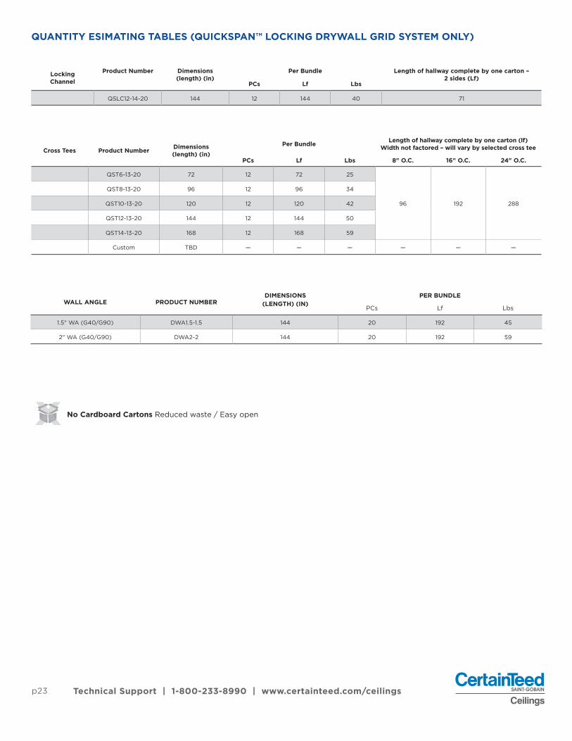
QUANTITY ESIMATING TABLES (QUICKSPAN™ LOCKING DRYWALL GRID SYSTEM ONLY)
Locking Channel
Product Number Dimensions (length) (in)
Per Bundle Length of hallway complete by one carton – 2 sides (Lf)
PCs Lf Lbs
QSLC12-14-20 144 12 144 40 71
Cross Tees Product Number Dimensions (length) (in)
Per Bundle Length of hallway complete by one carton (lf)Width not factored – will vary by selected cross tee
PCs Lf Lbs 8" O.C. 16" O.C. 24" O.C.
QST6-13-20 72 12 72 25
96 192 288
QST8-13-20 96 12 96 34
QST10-13-20 120 12 120 42
QST12-13-20 144 12 144 50
QST14-13-20 168 12 168 59
Custom TBD — — — — — —
WALL ANGLE PRODUCT NUMBERDIMENSIONS
(LENGTH) (IN)PER BUNDLE
PCs Lf Lbs
1.5" WA (G40/G90) DWA1.5-1.5 144 20 192 45
2" WA (G40/G90) DWA2-2 144 20 192 59
No Cardboard Cartons Reduced waste / Easy openXXXXX
© 06/18 CertainTeed. Printed in U.S.A. CTC-06-302
CertainTeed Suspension Systems | Fast. Easy. Reliable. A simple formula for success.20 Moores Road Malvern, PA 19355 Customer Support: 800-233-8990 certainteed.com/ceilings


