January 2008 Rev. 0.3 150 – 1500 Mbps Cable Extender Chipset (DS15BA101/DS15EA101) Evaluation Kit USER MANUAL Part Number: DriveCable02EVK NOPB For the latest documents concerning these products and evaluation kit, visit lvds.national.com. Schematics and gerber files are also available at lvds.national.com.
Transcript
January 2008 Rev. 0.3
150 – 1500 Mbps Cable Extender Chipset
(DS15BA101/DS15EA101) Evaluation Kit
USER MANUAL
Part Number: DriveCable02EVK NOPB For the latest documents concerning these products and evaluation kit, visit lvds.national.com. Schematics
and gerber files are also available at lvds.national.com.
DriveCable02EVK User Manual
Table of Contents
Overview ................................................................................................................................................ 3 Board Description................................................................................................................................... 4 Setting Up the DriveCable02EVK Evaluation Kit ................................................................................. 5 Evaluation with the 100-ohm Differential Balanced Cables .................................................................. 6 Evaluation with the 50-ohm Coaxial Cables ........................................................................................ 10
Page 2 of 12
DriveCable02EVK User Manual
Overview The DriveCable02EVK is an evaluation kit designed for demonstrating performance of the DS15BA101 and DS15EA101, a cable extender chipset. The kit enables evaluation of the chipset with 100-ohm differential cables such as twin-axial and low cost CAT5e/6/7 twisted pair cables and 50-ohm coaxial cables. The purpose of this document is to: familiarize you with the DriveCable02EVK, suggest the test setup procedures and instrumentation, and guide you through some typical measurements that demonstrate performance of the chipset in typical applications.
Page 3 of 12
DriveCable02EVK User Manual
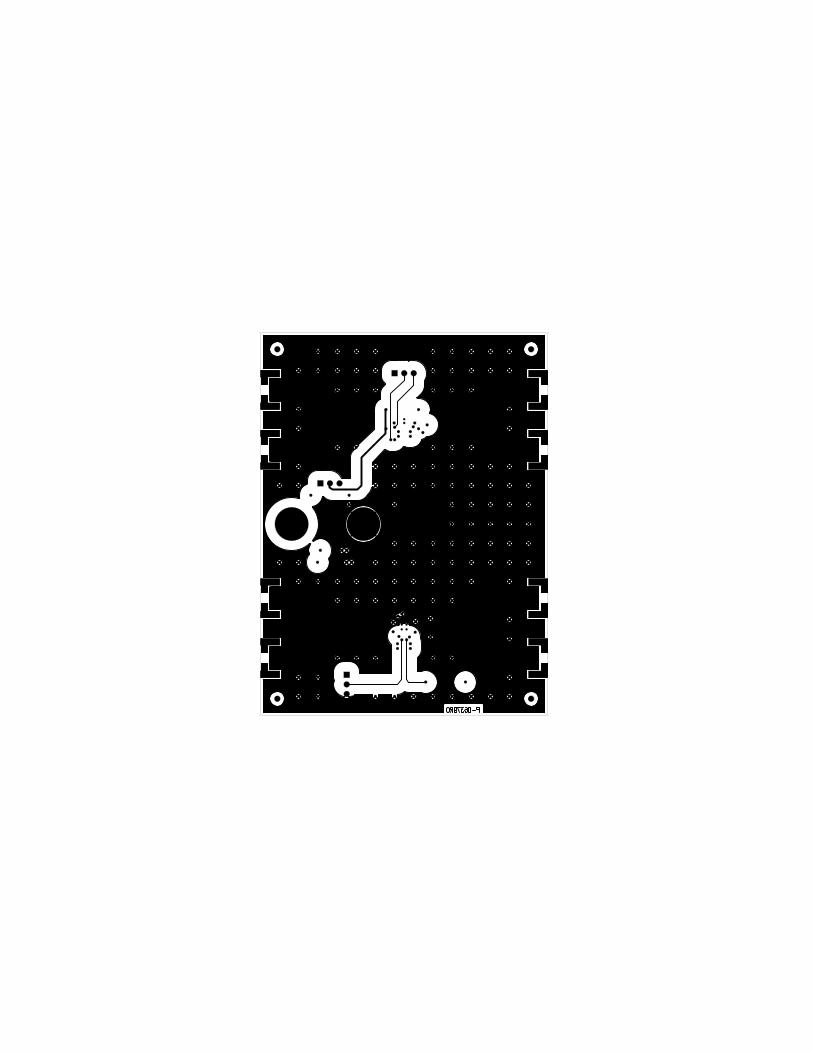
Board Description Figure 1 shows a drawing of the board. It is a 3 inch x 4 inch 6-layer PCB with a two-device layout that is capable of demonstrating performance and all features of the DS15BA101 and DS15EA101.
VD
D
Vbia
s
GN
D
Figure 1. DriveCable02EVK Board
Connector Device Function JP1 U1 Select output amplitude JP2 U2 Output enable JP3 U1 Set input common mode
Setting Up the DriveCable02EVK Evaluation Kit This section provides a quick reference for setting up some typical test configurations using the DriveCable02EVK that will enable you to evaluate the solution with 100-ohm differential cables (twin-axial and twisted pair cables) as well as 50-ohm coaxial cables.
Page 5 of 12
DriveCable02EVK User Manual
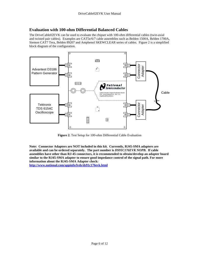
Evaluation with 100-ohm Differential Balanced Cables The DriveCable02EVK can be used to evaluate the chipset with 100-ohm differential cables (twin-axial and twisted pair cables). Examples are CAT5e/6/7 cable assemblies such as Belden 1500A, Belden 1700A, Siemon CAT7 Tera, Belden 89207 and Amphenol SKEWCLEAR series of cables. Figure 2 is a simplified block diagram of the configuration.
Figure 2. Test Setup for 100-ohm Differential Cable Evaluation
Note: Connector Adapters are NOT included in this kit. Currently, RJ45-SMA adapters are available and can be ordered separately. The part number is DS91C176EVK NOPB. If cable assemblies have other than RJ-45 connectors, it is recommended to obtain/develop an adapter board similar to the RJ45-SMA adapter to ensure good impedance control of the signal path. For more information about the RJ45-SMA Adapter check: http://www.national.com/appinfo/lvds/ds91c176evk.html
Follow these steps to set up the DriveCable02EVK for evaluation with 100-ohm differential balanced cables:
1. Configure DriveCable02EVK board:
a) Provide 3.3 V between the J2 (VDD) and J1 (GND). This powers all devices on the board. b) Set DS15BA101 (U1) output voltage amplitude to 0.4 V by using JP1. c) Enable DS15EA101 (U2) outputs by setting its EN* pin to low. This is accomplished by
placing a jumper across the GND and SIG pins of the connector JP2.
2. Connect the DS15BA101 inputs to a signal source (e.g. Pattern Generator or Serializer output). a) Note the AC-coupling capacitors on the inputs (SMA1 and SMA2) b) Adjust the signal parameters (VOH, VOL, VCM) so that they comply with the DS15BA101
input requirements. c) If DC-coupled interface is desired, use 0-ohm SM0402 resistors in place of the C1 and C2. d) There is a provision to add an optional resistor divider network (R12 and R13) on the
DS15BA101 inputs in case one desires biasing the input signal externally (note: there is already an internal biasing network on the DS15BA101 inputs). In addition, the JP3 connector provides signal biasing provision for a voltage source.
3. Attach the connector adapters (if available) to the DS15BA101 outputs (SMA3 and SMA4) and
DS15EA101 inputs (SMA5 and SMA6). 4. Connect a 100-ohm cable assembly with corresponding plugs on its ends.
5. The LED1 will illuminate if the DS15EA101 (U2) detects a valid signal. 6. Connect the DS15EA101 (U2) outputs directly to an oscilloscope, a bit error rate tester (BERT)
receiver or a deserializer using good quality coaxial cables. Note that the equalizer outputs have internal 50-ohm pull-ups and that there are on-board AC-coupling capacitors.
7. Observe the results on the oscilloscope or BERT receiver.
Page 7 of 12
DriveCable02EVK User Manual
Figure 3 presents typical maximum data rate as a function of CAT5e cable length. The data was collected on four chipsets (A, B, C and D). The data in red was taken with the 0.5 UI jitter criteria while the data in blue was taken with the 0.25 UI jitter criteria.
0.00
0.25
0.50
0.75
1.00
1.25
1.50
1.75
2.00
2.25
2.50
0 25 50 75 100 125
Cable Length [m]
Max
imum
Dat
a R
ate
[Gbp
s]A B C D A B C D
Figure 3. DS15BA101 and DS15EA101 Performance with CAT5e Cable
Page 8 of 12
DriveCable02EVK User Manual
Figure 4 presents maximum data rate as a function of CAT7 cable length. The data was collected on four chipsets (A, B, C and D). The data in red was taken with the 0.5 UI jitter criteria while the data in blue was taken with the 0.25 UI jitter criteria.
0.00
0.25
0.50
0.75
1.00
1.25
1.50
1.75
2.00
2.25
2.50
2.75
3.00
0 25 50 75 100
Cable Length [m]
Max
imum
Dat
a R
ate
[Gbp
s]A B C D A B C D
Figure 4. DS15BA101 and DS15EA101 Performance with CAT7 Cable
Page 9 of 12
DriveCable02EVK User Manual
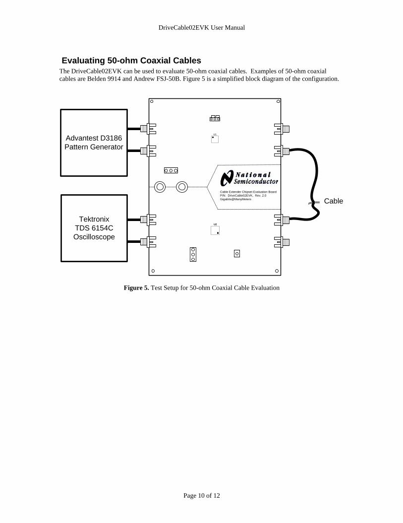
Evaluating 50-ohm Coaxial Cables The DriveCable02EVK can be used to evaluate 50-ohm coaxial cables. Examples of 50-ohm coaxial cables are Belden 9914 and Andrew FSJ-50B. Figure 5 is a simplified block diagram of the configuration.
Figure 5. Test Setup for 50-ohm Coaxial Cable Evaluation
Page 10 of 12
DriveCable02EVK User Manual
Follow these steps to set up the DriveCable02EVK for evaluation with 50-ohm coaxial cables: 1. Configure DriveCable02EVK board:
a) Provide 3.3 V between the J2 (VDD) and J1 (GND). This powers all devices on the board. b) Set DS15BA101 (U1) output voltage amplitude to 0.8 V by using JP1. c) Enable DS15EA101 (U2) outputs by setting its EN* pin to low. This is accomplished by
placing a jumper across the GND and SIG pins of the connector JP2. d) Remove R8 and place 50-ohm to GND termination on the DS15EA101 input that will be
used (R9 or R10) and 25-ohm to GND termination on the DS15EA101 input that will NOT be used (R9 or R10).
2. Connect the cable driver inputs to a signal source (e.g. Pattern Generator).
e) Note the AC-coupling capacitors on the inputs (SMA1 and SMA2) f) Adjust the signal parameters (VOH, VOL, VCM) so that they comply with the DS15BA101
input requirements. g) If DC-coupled interface is desired, use 0-ohm SM0402 resistors in place of the C1 and C2. h) There is a provision to add an optional resistor divider network (R12 and R13) on the
DS15BA101 inputs in case one desires bias the signal externally (there is an internal biasing network on the DS15BA101 inputs). In addition, the JP3 connector provides signal biasing provision for a voltage source.
3. Use SMA-to-BNC Adapters (i.e. PE9074 from www.pasternack.com) if necessary (in case coaxial cable has BNC connectors).
4. Connect a coaxial cable assembly with coresponding connectors on its ends.
5. The LED1 will illuminate if the DS15EA101 (U2) detects a valid signal.
6. Connect equalizer outputs directly to an oscilloscope or a bit error rate tester (BERT) receiver
using good quality coaxial cables. Note that the equalizer outputs have internal 50-ohm pull-ups and that there are on-board AC-coupling capacitors.
7. Observe the results on the oscilloscope or BERT receiver.
Page 11 of 12
DriveCable02EVK User Manual
Figure 6 presents maximum data rate as a function of Belden 9914 cable length. The data was collected on two chipsets (A and B). The data in red was taken with the 0.5 UI jitter criteria while the data in blue was taken with the 0.25 UI jitter criteria.
0.00
0.25
0.50
0.75
1.00
1.25
1.50
1.75
2.00
2.25
2.50
2.75
3.00
0 100 200 300
Cable Length [m]
Max
imum
Dat
a R
ate
[Gbp
s]A B A B
Figure 6. DS15BA101 and DS15EA101 Performance with Belden 9914 Cable
Page 12 of 12
To: Date: 11/27/2007 Company: From: Gordon GalbraithPhone: Phone: (503) 992-4448Fax: Fax:
Layer 1 (ref 2); 18.00 mil lines for 50 ohms +/-10% (model 49.69) 8.50 mil lines/14 mil pitch for 100 ohm differential +/-10% (model 98.9)
IMPORTANT NOTICE
Texas Instruments Incorporated and its subsidiaries (TI) reserve the right to make corrections, modifications, enhancements, improvements,and other changes to its products and services at any time and to discontinue any product or service without notice. Customers shouldobtain the latest relevant information before placing orders and should verify that such information is current and complete. All products aresold subject to TI’s terms and conditions of sale supplied at the time of order acknowledgment.
TI warrants performance of its hardware products to the specifications applicable at the time of sale in accordance with TI’s standardwarranty. Testing and other quality control techniques are used to the extent TI deems necessary to support this warranty. Except wheremandated by government requirements, testing of all parameters of each product is not necessarily performed.
TI assumes no liability for applications assistance or customer product design. Customers are responsible for their products andapplications using TI components. To minimize the risks associated with customer products and applications, customers should provideadequate design and operating safeguards.
TI does not warrant or represent that any license, either express or implied, is granted under any TI patent right, copyright, mask work right,or other TI intellectual property right relating to any combination, machine, or process in which TI products or services are used. Informationpublished by TI regarding third-party products or services does not constitute a license from TI to use such products or services or awarranty or endorsement thereof. Use of such information may require a license from a third party under the patents or other intellectualproperty of the third party, or a license from TI under the patents or other intellectual property of TI.
Reproduction of TI information in TI data books or data sheets is permissible only if reproduction is without alteration and is accompaniedby all associated warranties, conditions, limitations, and notices. Reproduction of this information with alteration is an unfair and deceptivebusiness practice. TI is not responsible or liable for such altered documentation. Information of third parties may be subject to additionalrestrictions.
Resale of TI products or services with statements different from or beyond the parameters stated by TI for that product or service voids allexpress and any implied warranties for the associated TI product or service and is an unfair and deceptive business practice. TI is notresponsible or liable for any such statements.
TI products are not authorized for use in safety-critical applications (such as life support) where a failure of the TI product would reasonablybe expected to cause severe personal injury or death, unless officers of the parties have executed an agreement specifically governingsuch use. Buyers represent that they have all necessary expertise in the safety and regulatory ramifications of their applications, andacknowledge and agree that they are solely responsible for all legal, regulatory and safety-related requirements concerning their productsand any use of TI products in such safety-critical applications, notwithstanding any applications-related information or support that may beprovided by TI. Further, Buyers must fully indemnify TI and its representatives against any damages arising out of the use of TI products insuch safety-critical applications.
TI products are neither designed nor intended for use in military/aerospace applications or environments unless the TI products arespecifically designated by TI as military-grade or "enhanced plastic." Only products designated by TI as military-grade meet militaryspecifications. Buyers acknowledge and agree that any such use of TI products which TI has not designated as military-grade is solely atthe Buyer's risk, and that they are solely responsible for compliance with all legal and regulatory requirements in connection with such use.
TI products are neither designed nor intended for use in automotive applications or environments unless the specific TI products aredesignated by TI as compliant with ISO/TS 16949 requirements. Buyers acknowledge and agree that, if they use any non-designatedproducts in automotive applications, TI will not be responsible for any failure to meet such requirements.
Following are URLs where you can obtain information on other Texas Instruments products and application solutions:
Products Applications
Audio www.ti.com/audio Automotive and Transportation www.ti.com/automotive
Amplifiers amplifier.ti.com Communications and Telecom www.ti.com/communications
Data Converters dataconverter.ti.com Computers and Peripherals www.ti.com/computers