Evaluate: DS2775–DS2778 DS2775–DS2778 Evaluation Kits ________________________________________________________________ Maxim Integrated Products 1 19-4673; Rev 2; 10/09 For pricing, delivery, and ordering information, please contact Maxim Direct at 1-888-629-4642, or visit Maxim’s website at www.maxim-ic.com. General Description The DS2775–DS2778 evaluation kits (EV kits) make per- formance evaluation, software development, and proto- typing with the DS2775–DS2778 2-cell stand-alone fuel-gauge ICs with Li-Ion (Li+) protector and SHA-1 authentication easy. The evaluation boards interface to a PC through a DS9123O USB adapter and RJ11 cable connection. The provided CD-ROM contains all related data sheets along with the evaluation software, which can be run under any Windows XP ® or older operating system (OS) that supports USB operation. The DS2775–DS2778 EV kit software gives the user complete control of all the DS2775–DS2778 functions. Separate control tabs allow the user access to all EEPROM and RAM memory locations, control registers, real-time updates of all monitored parameters, and SHA-1 functions. The software also incorporates a data- logging feature to monitor a cell over time. The evaluation board circuit is designed to provide the DS2775–DS2778 with accurate parameter measure- ments. Kit demonstration boards vary as they are improved upon over time. Evaluation Kit Contents 1 pc. Evaluation Board 1 pc. DS9123O USB Adapter 1 pc. RJ11 Cable Features ♦ Demonstrate the Capabilities of the DS2775–DS2778 Including: Estimation of Available Capacity for Li+ Cells 2-Cell Voltage Measurement Current Measurement Current Accumulation Temperature Measurement Information Storage Identification Overvoltage/Undervoltage Protection Overcurrent/Short-Circuit Protection Secure Challenge and Response Authentication Using the SHA-1 Algorithm (DS2776 and DS2778 Only) ♦ Interface to the USB Port of a PC Running a Windows XP or Older OS That Supports USB Operation Ordering Information Equipment Needed 1) A PC running a Windows XP or older OS with a CD- ROM drive and an available USB port. 2) Cables with minigrabber-style clips or the ability to solder directly to connection pads. 3) A Li+ battery and a power supply and/or load circuit. PART TYPE DS2775EVKIT+ EV Kit DS2776EVKIT+ EV Kit DS2777EVKIT+ EV Kit DS2778EVKIT+ EV Kit Windows XP is a registered trademark of Microsoft Corp. +Denotes lead(Pb)-free and RoHS compliant.
For pricing, delivery, and ordering information, please contact Maxim Direct at 1-888-629-4642,or visit Maxim’s website at www.maxim-ic.com.
General DescriptionThe DS2775–DS2778 evaluation kits (EV kits) make per-formance evaluation, software development, and proto-typing with the DS2775–DS2778 2-cell stand-alonefuel-gauge ICs with Li-Ion (Li+) protector and SHA-1authentication easy. The evaluation boards interface toa PC through a DS9123O USB adapter and RJ11 cableconnection. The provided CD-ROM contains all relateddata sheets along with the evaluation software, whichcan be run under any Windows XP® or older operatingsystem (OS) that supports USB operation.
The DS2775–DS2778 EV kit software gives the usercomplete control of all the DS2775–DS2778 functions.Separate control tabs allow the user access to all EEPROM and RAM memory locations, control registers,real-time updates of all monitored parameters, andSHA-1 functions. The software also incorporates a data-logging feature to monitor a cell over time.
The evaluation board circuit is designed to provide theDS2775–DS2778 with accurate parameter measure-ments. Kit demonstration boards vary as they areimproved upon over time.
Note: In the following sections, software-related itemsare identified by bolding. Text in bold refers to itemsdirectly from the EV kit software. Text in bold andunderlined refers to items from the Windows operatingsystem.
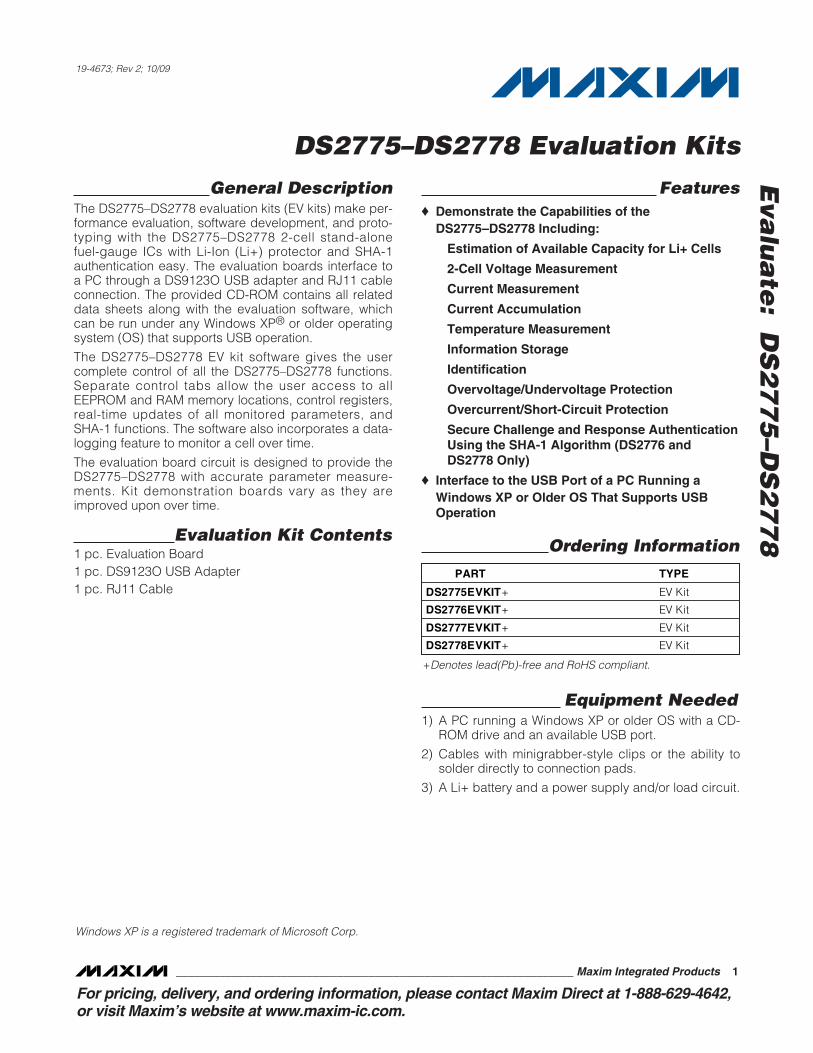
Connections to the TDFN demonstration board are bestmade either by soldering directly to the pads or byusing cables with minigrabber clips. Communication tothe TDFN board can be accomplished either throughthe RJ11 jack by connecting the provided standard six-conductor RJ11 cord, by wiring directly to the DQ andP- pads for the DS2775/DS2776, or by wiring directly tothe SDA, SCL, and P- pads for the DS2777/DS2778. Touse the demonstration software, the required communi-cation lines must be connected to the DS9123O com-munication brick using either of the two methodsdescribed.
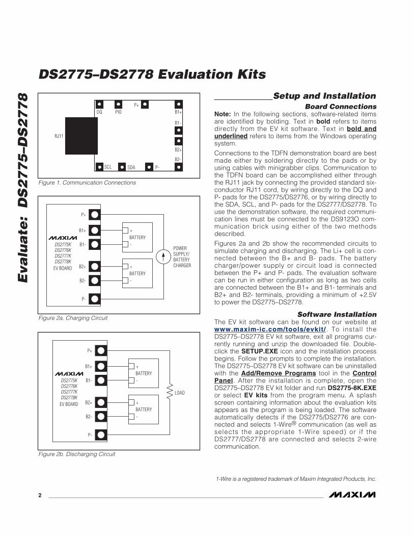
Figures 2a and 2b show the recommended circuits tosimulate charging and discharging. The Li+ cell is con-nected between the B+ and B- pads. The batterycharger/power supply or circuit load is connectedbetween the P+ and P- pads. The evaluation softwarecan be run in either configuration as long as two cellsare connected between the B1+ and B1- terminals andB2+ and B2- terminals, providing a minimum of +2.5Vto power the DS2775–DS2778.
Software InstallationThe EV kit software can be found on our website atwww.maxim-ic.com/tools/evkit/ . To install theDS2775–DS2778 EV kit software, exit all programs cur-rently running and unzip the downloaded file. Double-click the SETUP.EXE icon and the installation processbegins. Follow the prompts to complete the installation.The DS2775–DS2778 EV kit software can be uninstalledwith the Add/Remove Programs tool in the ControlPanel. After the installation is complete, open theDS2775–DS2778 EV kit folder and run DS2775-8K.EXEor select EV kits from the program menu. A splashscreen containing information about the evaluation kitsappears as the program is being loaded. The softwareautomatically detects if the DS2775/DS2776 are con-nected and selects 1-Wire® communication (as well asselects the appropriate 1-Wire speed) or if theDS2777/DS2778 are connected and selects 2-wirecommunication.
RJ11
SDA P-
DQ B1+
SCL
PIOP+
B1-
B2+
B2-
Figure 1. Communication Connections
P+
B1+
B1-
B2+
B2-
+BATTERY
BATTERY
-
+
-
P-
DS2775KDS2776KDS2777KDS2778K
EV BOARD
POWERSUPPLY/BATTERYCHARGER
Figure 2a. Charging Circuit
P+
B1+
B1-
B2+
B2-
+BATTERY
BATTERY
-
+
-
P-
DS2775KDS2776KDS2777KDS2778K
EV BOARD
LOAD
Figure 2b. Discharging Circuit
1-Wire is a registered trademark of Maxim Integrated Products, Inc.
Selecting the Communication PortIf the DS9123O is connected when the DS2775–DS2778 EV kits start, the software starts up automati-cally. If it is not connected, the Select Preferenceswindow opens (Figure 3).
In this window, select either Serial Port or USB and thePort Number, then click OK. The DS2775–DS2778 EVkit software saves this port selection and automaticallyuses the selection each time the program starts. Tochange the port later, click the Preferences option
(Figure 10) on the menu bar, select Edit Preferences,and then select the appropriate port. To attempt toautomatically locate the DS9123O or DS9123, click thePoll Ports button. Warning: Automatically polling forthe DS9123 can disrupt other devices connected toyour computer’s COM ports.
Program MenusSeveral pulldown menu options are provided to simplifyusing the DS2775–DS2778 EV kit software. Their func-tions are individually detailed in the following sections.
The File menu (Figure 4) allows the user to store andrecall information to and from a file directly into the textboxes on the Parameters tab (Figure 24). These func-tions do not directly write or read the DS2775–DS2778.It is still necessary for the user to store or recall thisinformation to or from the device by clicking on theWrite & Copy or Recall & Read buttons on theParameters tab (Figure 24).
The Registers Menu (Figure 5) gives immediateaccess to all seven status and function registers of theDS2775–DS2778. Selecting any of the registers opensan individual control window, giving the user a descrip-tion of each register bit and the ability to read or write it.See Figure 6.
The present state of all register bits is displayed imme-diately upon opening the register window. R/W loca-tions contain a selection field or command button toallow the user to determine their state. Pressing theWrite button writes the new value to the register andreads the corresponding register inside theDS2775–DS2778 to verify the correct value was written.The Control register and Protection Threshold registerare stored in EEPROM, so when the Write command is
issued, the value is written and copied to EEPROMwithout changing the values of the remainder of theParameter EEPROM block.
The Communication menu (Figure 7) allows the userto detect the appropriate communication protocol forthe device in use. The DS2775–DS2778 EV kits auto-matically detect which device type is connected anddisplay the appropriate information.
If the DS2775/DS2776 are found by the software, the1-Wire speed of the device is detected and displayed.To change the speed of the device, simply left-click onSet Overdrive or Clear Overdrive from theCommunication menu (Figure 7). Selecting eitheroption sends the Clear Overdrive or Set Overdrivecommand. The software sends the command in thecurrent 1-Wire speed, and then begins communicatingin the new 1-Wire speed.
If the D2777/DS2778 are found by the software, the2-wire slave address is detected and displayed underthe Communication menu. If the software and theDS2775–DS2778 get out of sync, simply left-click onDetect Device to match the software’s communicationto the device.
The Tools menu (Figure 8) provides two methods toevaluate the SHA-1 calculations: a method to view thesoftware-computed MAC and a method to view theSHA-1 calculator. Left-clicking on the Show SoftwareComputed MAC menu item expands the main windowto show the MAC computed by the software.
Left-clicking on the Show SHA-1 Calculator menuitem opens a new window that allows the user to per-form SHA-1 calculations independent of the DS2775–DS2778 (Figure 9). Simply fill in the text boxes with thedesired values and left-click on the Compute MACwith Software button. If the ROM ID is to be used incomputing the MAC, check the Use ROM ID? check-box. Use the Fill with Values from Main Form optionfrom the Options menu to fill the Secret, ROM ID, andChallenge text boxes with values from the main pro-gram window.
The Preferences menu allows the user to changeCOM port settings at any time (Figure 10). EditPreferences opens the Select Preferences window.See the Selecting the Communication Port section formore information.
Selecting the About topic from the Help menu (Figure11) opens a window containing information about thecurrent revision of this program and Maxim IntegratedProducts, Inc.
Program TabsAll program functions are divided under four tabs in themain program window. Left-click on the appropriate tabto move to the desired function page. Located on theReal Time tab (Figure 12) is all the information mea-sured and calculated by the DS2775–DS2778. Thatdata is divided between the Parametric Data, FuelGauge Data, and SHA-1 subtabs. The Parameters tab(Figure 24) gives the user access to the entire parame-ter EEPROM memory block in terms of application unitsand device units. The Memory tab (Figure 26) displaysthe contents of every register and memory locationinside the DS2775–DS2778 and allows the user to alterthe data. The Log Data tab (Figure 27) allows the userto store all real-time information to a file and view thedata in a graphical form.
Real Time TabThe Real Time data tab is divided into three subtabs:Parametric Data, Fuel Gauge Data, and SHA-1. TheParametric Data subtab (Figure 12) contains all thereal-time measurements taken by the DS2775–DS2778.The Fuel Gauge Data subtab contains all the fuel-gauge values calculated by the DS2775–DS2778. TheSHA-1 subtab allows the user to exercise the SHA-1encryption algorithm. The SHA-1 functions are onlysupported by the DS2776 and DS2778.
The Parametric Data subtab displays the latest real-time measurements of cell voltages, temperature, cur-rent, and accumulated charge with both analog meterreadouts and digital values. The sense-resistor valueused to calculate the current reading is shown in theTemperature section. Go to the Sense Resistor(mOhms) value on the Parameters tab (Figure 24) tochange this value.
The present states of the charge control and dischargecontrol pins are shown at the bottom of the window.These outputs are active low and drive two control FETs,allowing charging and discharging of the cell pack. Thecharge control pin can be controlled manually by left-clicking the Disable Charging and Enable Chargingbuttons and is forced high automatically by either anovervoltage or charge overcurrent condition. The dis-charge control pin can also be controlled manually withthe Disable Discharging and Enable Discharging but-tons and is forced high automatically by either an under-voltage or discharge overcurrent condition.
The present state of each of the four possible flag con-ditions (overvoltage, undervoltage, charge overcurrent,and discharge overcurrent) are represented by LEDsinside the voltage and current sections of the window.The corresponding LED is green while the flag is in thecleared state. If conditions cause a flag to be tripped,the LED turns red and a button appears that allows theuser to clear the flag, provided that clear conditionshave been met. If conditions for clearing the flag havenot been met by the circuit, clicking the Clear buttonhas no effect.
Figure 10. Preferences Menu
Figure 11. Help Menu
The present state of the PIO pin is shown in text. TheSet/Clear PIO bit button sets or clears the PIO bit inthe Special Feature register to toggle the pin’s state.
The user can bring up the Set Accumulated CurrentRegister window (Figure 13) by left-clicking the SetACR button. This window allows the user to enter avalue for the Accumulated Current register in mAhrs.
The user can bring up the Set Accumulation BiasRegister window (Figure 14) by left-clicking the AccBias button. This window allows the user to enter val-ues for the Accumulation Bias register in mA. Left-click-ing on the Write button writes the Accumulation Biasregister and copies the value to EEPROM. The valueentered here is added to the Accumulated Current reg-ister during each current conversion. The bias valuedoes not affect the Current register reading but isreflected in the Accumulated Current register.
The user can bring up the Set Current Offset BiasRegister window (Figure 15) by left-clicking theCurrent Offset Bias button. This window allows theuser to enter values for the Current Offset Bias registerin mA. Left-clicking on the Write button writes theCurrent Offset Bias register and copies the value toEEPROM. The value entered here is added to theCurrent register during each current conversion. Theuser can start an automatic current offset calibration byleft-clicking on the Calibrate button.
The Fuel Gauge Data subtab displays the latest fuel-gauge calculations (Figure 16). The Full, ActiveEmpty, and Stand-by Empty levels are calculatedfrom the data input on the Parameters tab (Figure 24).The remaining active absolute capacity (RAAC) andthe remaining stand-by absolute capacity (RSAC) aredisplayed in terms of mAhr. The remaining active rela-tive capacity (RARC) and remaining stand-by relativecapacity (RSRC) are displayed in terms of percent ofcapacity remaining. The analog meter on the left dis-plays the remaining active absolute capacity (RAAC).
The flags found in the Status register are displayed onthe right side of the window. When the Under Voltageflag or the Power-On-Reset flag is set, a buttonappears that allows the user to clear those bits. Theuser can also issue a Software Power-On Reset com-mand by left-clicking the Soft POR button.
Figure 14. Set Accumulation Bias Register Figure 15. Set Current Offset Bias Register
The user can bring up the Set Age Scalar window(Figure 17) by left-clicking the Update button in theScalar area of the Fuel Gauge Data subtab. This win-dow allows the user to read and write the scalar valuein terms of percent of the nominal capacity.
The DS2776/DS2778 use an 8-byte Secret, the 8-byteROM ID code of the device, and an 8-byte Challengeto generate a 20-byte Message Digest (also called theMAC) using the SHA-1 encryption algorithm. SeeFigure 18. The DS2775/DS2777 do not support theSHA-1 functions.
The user can clear the 8 bytes of the secret by left-clicking on the Clear Secret button. The top-right textbox is the LSB of the secret, and the bottom-left textbox is the MSB of the secret. (All text boxes are dis-played in this same format.) See Figure 19.
The user can also permanently lock the secret by left-clicking on the Lock Secret button. Once the secret islocked, it cannot be changed and cannot be read fromthe DS2776/DS2778. The software prompts the user tomake sure the secret is ready to be permanently locked.
Another DS2776/DS2778 feature is to generate the nextsecret from the existing secret, ROM ID, and challenge.It is important to click Write Challenge before left-click-ing the Compute Next Secret or Compute NextSecret with ID button. The device performs the SHA-1calculation and creates the next secret. The softwareperforms SHA-1 calculation based on the values in thetext boxes for the secret, ROM ID (if desired), and chal-lenge and places the new secret, as calculated by soft-ware, in the Secret text boxes. The new secret is neverread back from the device.
It is important for the software and the DS2776/DS2778to have identical secrets, ROM IDs, and challenges sothe software can properly verify the operation of theDS2776/DS2778. If the software is not in sync with thedevice, simply clear the secret to get the software andhardware back in sync.
The DS2776/DS2778 have two commands to computethe next secret. The Compute Next Secret with IDcommand uses the secret, the ROM ID, and the chal-lenge to perform the SHA-1 encryption algorithm. TheCompute Next Secret command uses the secret andthe challenge, but replaces the ROM ID with 0xFFs toperform the algorithm. The user can select which com-mand is used by left-clicking on the appropriate button.
The ROM ID code is unique for each DS2776/DS2778device and cannot be changed by the user. The usercan load the device’s ROM ID into the ROM ID textboxes by left-clicking on the Read ROM – 33h or ReadROM – 39h buttons, depending on the setting of theRNAOP bit of the Control register for the DS2776 or byleft-clicking on the READ ROM ID button for theDS2778. See Figure 20.
If multiple 1-Wire devices are on the bus, the user canuse the Search ROM function from the Net Addresssubtab of the Memory tab (Figure 26). Left-click theFind Devices button and then left-click on the ROM IDthat is desired to be used in the SHA-1 algorithm. Thevalue of the ROM ID appears in the ROM ID text boxeson the SHA-1 subtab of the Real Time tab (Figure 12).
The challenge is a random 8-byte block that is used bythe DS2776/DS2778 to perform the SHA-1 encryptionalgorithm (Figure 21). Each time the SHA-1 is per-formed, either during a Compute Next Secret (seeFigure 18) or a Compute MAC (see Figure 22), thechallenge is left in an undefined state. Therefore, theuser must left-click on the Write Challenge button priorto each computation to get a proper SHA-1 calculation.
The user can left-click on the Randomize Challengebutton to load a random challenge into the Challengetext boxes. Left-clicking this button does not write thechallenge to the device. It is still required that the userleft-click on the Write Challenge button to write thechallenge to the device.
The MAC is the 20-byte message digest that is theresult of the SHA-1 encryption algorithm (Figure 22).When the secret has been loaded properly, the ROM IDhas been read, and the challenge has been written tothe device, left-clicking on the Compute MAC orCompute MAC with ID button performs the SHA-1 cal-culation, reads back the results, and then displaysthem in the MAC text boxes.
The software also performs the SHA-1 calculationsbased on the Secret, ROM ID (if desired), andChallenge text box values and compares its results tothe results read back from the DS2776/DS2778. If theMAC computed by the software and MAC read backfrom the DS2776/DS2778 match, the software displays“Verified.” If they do not match, “Not Verified” is dis-played. The user can view the software-computed MACby selecting Show Software Computed MAC from theTools menu (Figure 8). The user also can compute theMAC with the DS2776/DS2778, then change one bit inone of the text boxes of the secret, and then computethe MAC with software to see how big of a differencechanging one bit makes. See Figure 23.
If the MAC is “Not Verified,” make sure that the chal-lenge was written prior to computing the MAC. If the“Not Verified” error continues, perhaps the secret in thedevice does not match what is in the Secret text boxesand the user needs to clear the secret of the DS2776/DS2778.
Parameters TabThe Parameters tab gives the user access to the entireparameter EEPROM memory block (block 1, addresses60h–7Fh) in terms of application units and device units.The Application Units subtab displays the parametersin units like mA, mAhrs, and V (Figure 24). The DeviceUnits (Read Only) subtab performs the calculationsneeded to get the application units into the units thatare stored in the device like µV, µVhrs, and ppm as well
as show the hexadecimal values that are written to thedevice.
The Application Units subtab allows the user to readand write the parameter EEPROM memory block. Tochange any of this information, simply click on thedesired text field and enter the new value.
Clicking on the Load Default Set Up button entersexample data into the information f ields of theApplication Units subtab. Once all data is in thedesired format, click on the Write & Copy button tocopy it to the DS2775–DS2778’s EEPROM.
This information can also be stored to a file andrecalled later using the Load Set up or Save Set Upbuttons or the Load Parameter Set up or SaveParameter Set up option from the File menu (Figure 4).
These functions do not directly write or read theDS2775–DS2778. It is still necessary for the user tostore or recall this information to or from the device byclicking the Write & Copy or Recall & Read buttons.
The Device Units (Read Only) subtab is read only. Itdisplays the actual hexadecimal values read from theDS2775–DS2778 and displays the units that are storedin the device. See Figure 25.
The Memory tab (Figure 26) gives the user access toall 32 bytes of SRAM and all 48 bytes of EEPROMinside the DS2775–DS2778. They are separated intofive subtabs for convenience. Any value can be modi-fied by clicking in that address’ text box and typing anew value in hexadecimal format. The Write button
copies the entire block of data to the correspondinglocation inside the DS2775–DS2778 (scratchpad RAMon the EEPROM blocks). The Read button updates theentire block’s text boxes with data from theDS2775–DS2778 (scratchpad RAM on the EEPROMblocks). Subtabs displaying any EEPROM data alsohave Copy and Recall buttons to allow the user totransfer the data between scratchpad and EEPROMmemory internal to the DS2775–DS2778. ThePermanently Lock Block 0 and Permanently LockBlock 1 buttons permanently store the data currentlylocated in that block’s EEPROM. Warning: This datacan never be changed once locked. Verify your datafirst by issuing a Recall and a Read.
The Net Address subtab allows the user to perform aSearch Net Address command to find all the 1-Wiredevices on the 1-Wire bus. All devices found on thebus are listed in the Addresses fields. To communicateto any device on the bus, click on its address inside theNet Addresses field to select it. The program now usesthis net address for all operations until a different netaddress is chosen. If a DS2776/DS2778 is detected,then a separate button is displayed to allow the user toread the ROM ID of the 2-wire device.
The Log Data tab allows the user to see theDS2775–DS2778’s real-time measurements graphedover time (Figure 27). There are separate subtabs forVoltage, Current, Temperature, and AccumulatedCharge. Each graph displays the last 500 data pointscollected by the DS2775–DS2778 EV kit software. Thesampling interval can be adjusted from as fast as pos-sible to 15min and can be adjusted from the SamplingInterval menu at the bottom of the window. The ClearGraphs button clears all data from all four graphs butdoes not reset the log to file function. The graphs arenot updated when the fastest sampling interval isselected, only the data logging is enabled.
The Log to File subtab contains control information forstoring all data to an ASCII file. The default file name isc:\DS277xK_datalog.txt, but can be modified in theFilename text field. The Stop Logging button togglesdata logging off and on. Data is stored at the sameinterval selected for updating the graphs in the tab-delimited format of:
“Time<tab>Voltage1<tab>Voltage2<tab>Current<tab>AveCurrent<tab>Temperature<tab>ACR<tab>Full<tab>AE<tab>SE<tab>RAAC<tab>RARC<tab>RSAC<tab>RSRC<tab>Status<tab>Protection<tab> Scalar” foreasy import into a spreadsheet. The most recent 50samples are displayed in the window for observation.Warning: The Log Data function overwrites previousfile information. Data previously stored in the filewill be lost.
1 7/09 • Added DS2775-DS2778 EV Kit Schematic.• Added link to EV kit software.
2, 15
2 10/09 Changed the Ordering Information table to reflect Pb-free part numbers. 1
Maxim cannot assume responsibility for use of any circuitry other than circuitry entirely embodied in a Maxim product. No circuit patent licenses areimplied. Maxim reserves the right to change the circuitry and specifications without notice at any time.
Maxim Integrated Products, 120 San Gabriel Drive, Sunnyvale, CA 94086 408-737-7600 ____________________ 17