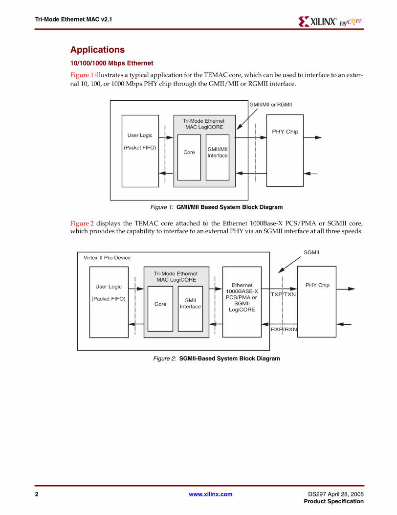
Figure 1 illustrates a typical application for the TEMAC core, which can be used to interface to an exter-nal 10, 100, or 1000 Mbps PHY chip through the GMII/MII or RGMII interface.
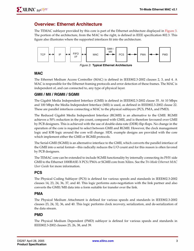
Figure 2 displays the TEMAC core attached to the Ethernet 1000Base-X PCS/PMA or SGMII core,which provides the capability to interface to an external PHY via an SGMII interface at all three speeds.
Figure Top x-ref 1
Figure 1: GMII/MII Based System Block Diagram
Figure Top x-ref 2
Figure 2: SGMII-Based System Block Diagram
Tri-Mode Ethernet MAC LogiCORE
User Logic
(Packet FIFO)Core GMII/MII
Interface
PHY Chip
GMII/MII or RGMII
Tri-Mode Ethernet MAC LogiCORE
Virtex-II Pro Device
User Logic
(Packet FIFO)Core
GMIIInterface
TXP/TXN
SGMII
Ethernet1000BASE-XPCS/PMA or
SGMIILogiCORE
PHY Chip
RXP/RXN
www.xilinx.com DS297 April 28, 2005Product Specification
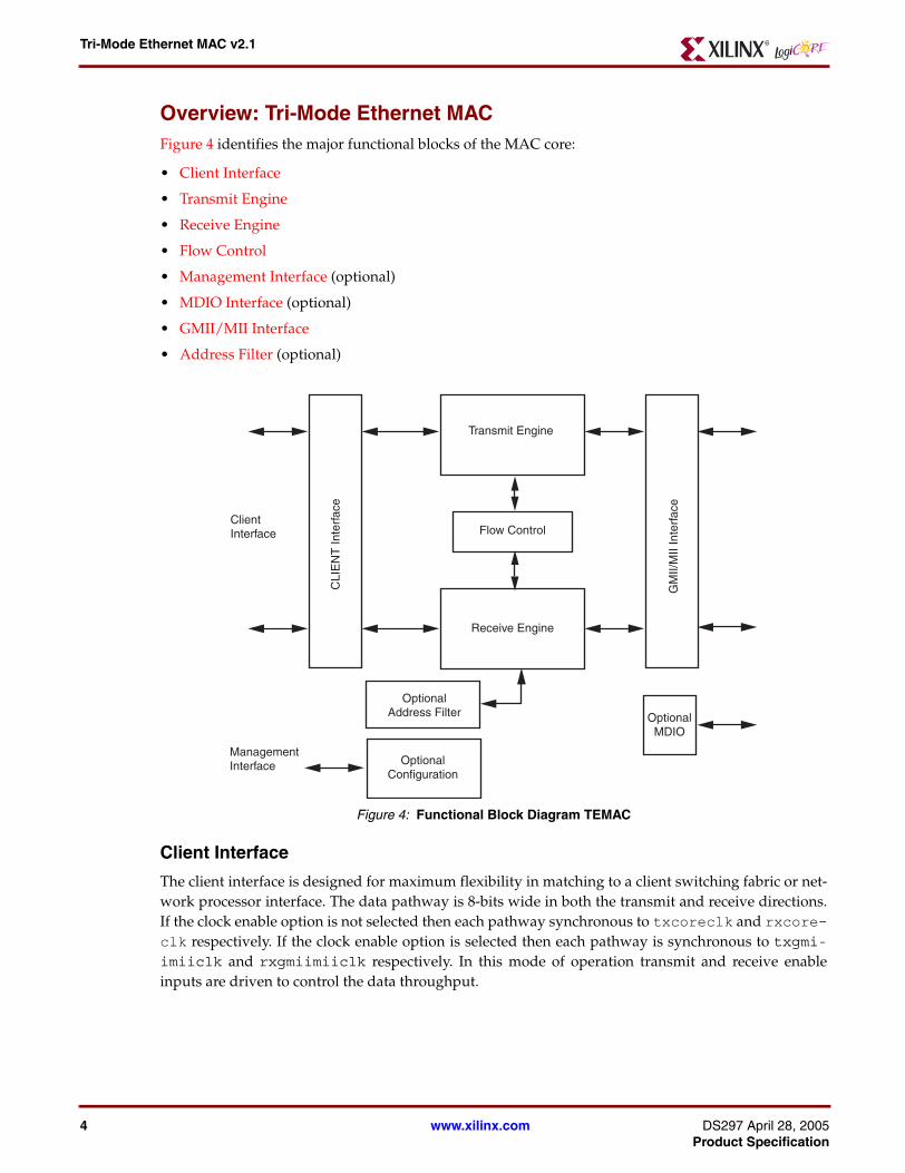
Overview: Ethernet ArchitectureThe TEMAC sublayer provided by this core is part of the Ethernet architecture displayed in Figure 3.The portion of the architecture, from the MAC to the right, is defined in IEEE specification 802.3. Thisfigure also illustrates where the supported interfaces fit into the architecture.
MAC
The Ethernet Medium Access Controller (MAC) is defined in IEEE802.3-2002 clauses 2, 3, and 4. AMAC is responsible for the Ethernet framing protocols and error detection of these frames. The MAC isindependent of, and can connected to, any type of physical layer.
GMII / MII / RGMII / SGMII
The Gigabit Media Independent Interface (GMII) is defined in IEEE802.3-2002 clause 35. At 10 Mbpsand 100 Mbps the Media Independent Interface (MII) is used, as defined in IEEE802.3-2002 clause 22.These are parallel interfaces connecting a MAC to the physical sublayers (PCS, PMA, and PMD).
The Reduced Gigabit Media Independent Interface (RGMII) is an alternative to the GMII. RGMIIachieves a 50% reduction in the pin count, compared with GMII, and is therefore favoured over GMIIby PCB designers. This is achieved with the use of double-data-rate (DDR) flip-flops. No change in theoperation of the core is required to select between GMII and RGMII. However, the clock managementlogic and IOB logic around the core will change. HDL example designs are provided with the corewhich implement either the GMII or RGMII protocols.
The Serial-GMII (SGMII) is an alternative interface to the GMII, which converts the parallel interface ofthe GMII into a serial format—this radically reduces the I/O count and for this reason is often favoredby PCB designers.
The TEMAC core can be extended to include SGMII functionality by internally connecting its PHY sideGMII to the Ethernet 1000BASE-X PCS/PMA or SGMII core from Xilinx. See the Tri-Mode Ethernet MACUser Guide for more information.
PCS
The Physical Coding Sublayer (PCS) is defined for various speeds and standards in IEEE802.3-2002clauses 14, 23, 24, 36, 37, and 40. This logic performs auto-negotiation with the link partner and alsoconverts the GMII/MII data into a form suitable for transfer over the link.
PMA
The Physical Medium Attachment is defined for various speeds and standards in IEEE802.3-2002clauses 23, 24, 32, 36, and 40. This logic performs clock recovery, serialization, and de-serialization ofthe data stream.
PMD
The Physical Medium Dependent (PMD) sublayer is defined for various speeds and standards inIEEE802.3-2002 clauses 25, 26, 38, and 39.
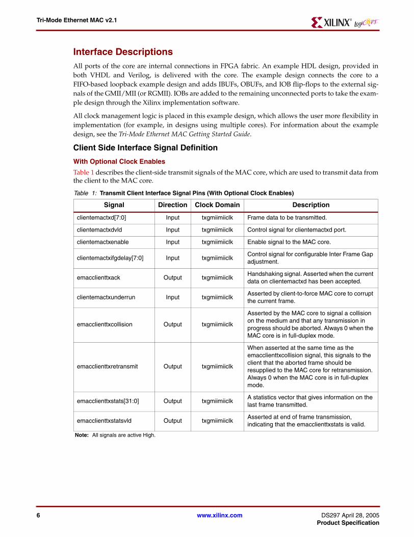
Overview: Tri-Mode Ethernet MAC Figure 4 identifies the major functional blocks of the MAC core:
• Client Interface
• Transmit Engine
• Receive Engine
• Flow Control
• Management Interface (optional)
• MDIO Interface (optional)
• GMII/MII Interface
• Address Filter (optional)
Client Interface
The client interface is designed for maximum flexibility in matching to a client switching fabric or net-work processor interface. The data pathway is 8-bits wide in both the transmit and receive directions.If the clock enable option is not selected then each pathway synchronous to txcoreclk and rxcore-clk respectively. If the clock enable option is selected then each pathway is synchronous to txgmi-imiiclk and rxgmiimiiclk respectively. In this mode of operation transmit and receive enableinputs are driven to control the data throughput.
Figure Top x-ref 4
Figure 4: Functional Block Diagram TEMAC
Flow Control
Transmit Engine
Receive Engine
GM
II/M
II In
terf
ace
CLI
EN
T In
terf
ace
OptionalConfiguration
OptionalMDIO
ClientInterface
ManagementInterface
OptionalAddress Filter
www.xilinx.com DS297 April 28, 2005Product Specification
Transmit EngineThe transmit engine takes data from the client and converts it to GMII format. Preamble and FrameCheck Sequence fields are added and the data is padded if necessary. The transmit engine also providesthe transmit statistics vector for each packet and transmits the pause frames generated by the flowcontrol module.
Receive EngineThe receive engine takes the data from the GMII/MII interface and checks it for compliance to the IEEE802.3 specification. Padding fields are removed and the client is presented with the data along with agood or bad frame indicator. The receive engine also provides the receive statists vector for eachreceived packet.
Flow ControlThe flow control block is designed to clause 31 of IEEE 802.3-2002. The MAC may be configured to sendpause frames with a programmable pause value and to act on their reception. These two behaviors canbe configured asymmetrically.
GMII/MII InterfaceThe GMII/MII interface takes the data from the transmitter and converts it to MII format if the deviceis operating at speeds under 1000 Mbps. The received data is converted into GMII format. At 1000Mbps the data is simply passed through.
Management InterfaceThe management interface (optional) is a processor-independent interface with standard address, data,and control signals. It is used for the configuration and monitoring of the TEMAC and for access to theMDIO Interface. It may be used as is, or a wrapper may be applied (not supplied) to interface tocommon bus architectures. This interface is optional. If it is not present the device can be configuredusing a configuration vector.
MDIO InterfaceThe MDIO interface (optional) can be written to and read from using the management interface. TheMDIO is used to monitor and configure PHY devices. The MDIO Interface is defined in IEEE802.3clause 22.
Address FilterThe TEMAC core can be implemented with an address filter (optional). If the address filter is enabledthe device will not pass frames that do not contain one of a set of known addresses to the client.
Interface DescriptionsAll ports of the core are internal connections in FPGA fabric. An example HDL design, provided inboth VHDL and Verilog, is delivered with the core. The example design connects the core to aFIFO-based loopback example design and adds IBUFs, OBUFs, and IOB flip-flops to the external sig-nals of the GMII/MII (or RGMII). IOBs are added to the remaining unconnected ports to take the exam-ple design through the Xilinx implementation software.
All clock management logic is placed in this example design, which allows the user more flexibility inimplementation (for example, in designs using multiple cores). For information about the exampledesign, see the Tri-Mode Ethernet MAC Getting Started Guide.
Client Side Interface Signal Definition
With Optional Clock Enables
Table 1 describes the client-side transmit signals of the MAC core, which are used to transmit data fromthe client to the MAC core.
clientemactxd[7:0] Input txgmiimiiclk Frame data to be transmitted.
clientemactxdvld Input txgmiimiiclk Control signal for clientemactxd port.
clientemactxenable Input txgmiimiiclk Enable signal to the MAC core.
clientemactxifgdelay[7:0] Input txgmiimiiclkControl signal for configurable Inter Frame Gap adjustment.
emacclienttxack Output txgmiimiiclkHandshaking signal. Asserted when the current data on clientemactxd has been accepted.
clientemactxunderrun Input txgmiimiiclkAsserted by client-to-force MAC core to corrupt the current frame.
emacclienttxcollision Output txgmiimiiclk
Asserted by the MAC core to signal a collision on the medium and that any transmission in progress should be aborted. Always 0 when the MAC core is in full-duplex mode.
emacclienttxretransmit Output txgmiimiiclk
When asserted at the same time as the emacclienttxcollision signal, this signals to the client that the aborted frame should be resupplied to the MAC core for retransmission. Always 0 when the MAC core is in full-duplex mode.
emacclienttxstats[31:0] Output txgmiimiiclkA statistics vector that gives information on the last frame transmitted.
emacclienttxstatsvld Output txgmiimiiclkAsserted at end of frame transmission, indicating that the emacclienttxstats is valid.
Note: All signals are active High.
www.xilinx.com DS297 April 28, 2005Product Specification
Figure 5 displays a typical frame transmission at the client interface at 10/100Mb/s. Figure 6 shows atypical frame transmission at 1000Mb/s. The client asserts clientemactxdvld and puts the first byteof frame data on the clientemactxd bus. The client then waits until the TEMAC assertsemacclienttxack before sending the rest of the data. At the end of the frame clientemactxdvldis de-asserted.
At 1000Mb/s clientemactxenable should be set high. At 10/100Mb/s clientemactxenablemust be toggled on the rising edge of txgmiimiiclk in order to provide the correct data throughputin the MAC core. All transmit client logic should also be enabled using the clientemactxenable sig-nal.Figure Top x-ref 5
Figure 5: Normal Frame Transmission at 10/100Mb/s with Clock Enables
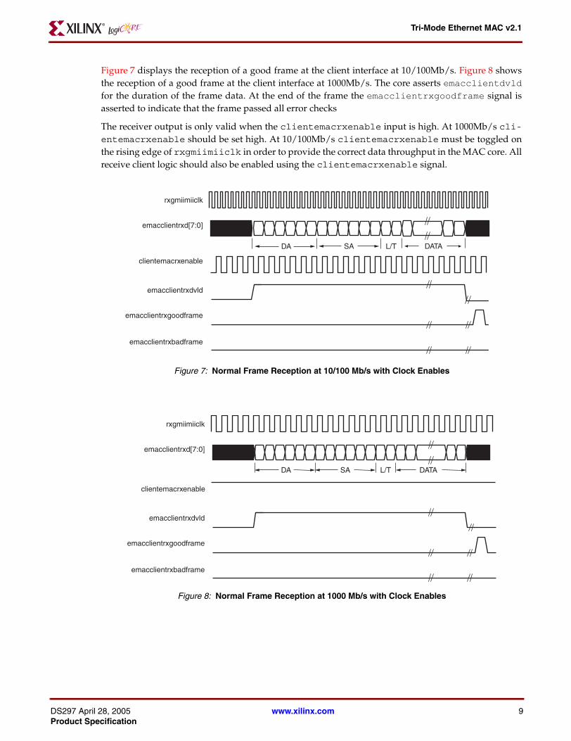
Figure 7 displays the reception of a good frame at the client interface at 10/100Mb/s. Figure 8 showsthe reception of a good frame at the client interface at 1000Mb/s. The core asserts emacclientdvldfor the duration of the frame data. At the end of the frame the emacclientrxgoodframe signal isasserted to indicate that the frame passed all error checks
The receiver output is only valid when the clientemacrxenable input is high. At 1000Mb/s cli-entemacrxenable should be set high. At 10/100Mb/s clientemacrxenable must be toggled onthe rising edge of rxgmiimiiclk in order to provide the correct data throughput in the MAC core. Allreceive client logic should also be enabled using the clientemacrxenable signal.
Figure Top x-ref 7
Figure 7: Normal Frame Reception at 10/100 Mb/s with Clock Enables
Figure Top x-ref 8
Figure 8: Normal Frame Reception at 1000 Mb/s with Clock Enables
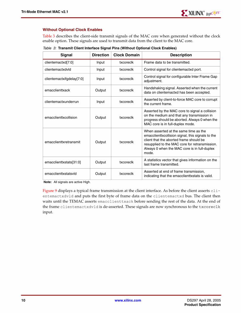
Table 3 describes the client-side transmit signals of the MAC core when generated without the clockenable option. These signals are used to transmit data from the client to the MAC core.
Figure 9 displays a typical frame transmission at the client interface. As before the client asserts cli-entemactxdvld and puts the first byte of frame data on the clientemactxd bus. The client thenwaits until the TEMAC asserts emacclienttxack before sending the rest of the data. At the end ofthe frame clientemactxdvld is de-asserted. These signals are now synchronous to the txcoreclkinput.
clientemactxd[7:0] Input txcoreclk Frame data to be transmitted.
clientemactxdvld Input txcoreclk Control signal for clientemactxd port.
clientemactxifgdelay[7:0] Input txcoreclkControl signal for configurable Inter Frame Gap adjustment.
emacclienttxack Output txcoreclkHandshaking signal. Asserted when the current data on clientemactxd has been accepted.
clientemactxunderrun Input txcoreclkAsserted by client-to-force MAC core to corrupt the current frame.
emacclienttxcollision Output txcoreclk
Asserted by the MAC core to signal a collision on the medium and that any transmission in progress should be aborted. Always 0 when the MAC core is in full-duplex mode.
emacclienttxretransmit Output txcoreclk
When asserted at the same time as the emacclienttxcollision signal, this signals to the client that the aborted frame should be resupplied to the MAC core for retransmission. Always 0 when the MAC core is in full-duplex mode.
emacclienttxstats[31:0] Output txcoreclkA statistics vector that gives information on the last frame transmitted.
emacclienttxstatsvld Output txcoreclkAsserted at end of frame transmission, indicating that the emacclienttxstats is valid.
Note: All signals are active High.
www.xilinx.com DS297 April 28, 2005Product Specification
Figure 10 displays the reception of a good frame at the client interface. The core assertsemacclientdvld for the duration of the frame data. At the end of the frame theemacclientrxgoodframe signal is asserted to indicate that the frame passed all error checks.
Table 5 describes the signals used by the client to request a flow control action from the transmit engine.Valid flow control frames received by the MAC are automatically handled (if the MAC is configured todo so). The pause value in the received frame is used to inhibit the transmitter operation for the timedefined in the IEEE802.3-2002 specification. The frame is then passed to the client withemacclientrxbadframe asserted to indicate to the client that it should be dropped.
Management Interface Signal Definition
Table 6 describes the optional signals used by the client to access the management features of the MACcore, including configuration, status and MDIO access.
Figure Top x-ref 9
Figure 10: Normal Frame Reception without Clock Enables
Table 5: Flow Control Interface Signal Pinout
Signal Direction Description
clientemacpausereq InputPause request: Upon request the MAC transmits a pause frame upon the completion of the current data packet.
clientemacpauseval[15:0] InputPause value: inserted into the parameter field of the transmitted pause frame.
Note: All signals are active High.
Table 6: Optional Management Interface Signal Pinout
Signal Direction Clock Domain Description
hostclk Input N/A Clock for management interface.
hostopcode[1:0] Input hostclkDefines operation to be performed over MDIO interface. Bit 1 is also used in configuration register access.
hostaddr[9:0] Input hostclk Address of register to be accessed.
hostwrdata[31:0] Input hostclk Data to write to register.
hostrddata[31:0] Output hostclk Data read from register.
rxcoreclk
emacclientrxd[7:0]
emacclientrxdvld
emacclientrxgoodframe
emacclientrxbadframe
DA SA DATAL/T
www.xilinx.com DS297 April 28, 2005Product Specification
After power up or reset, the client may reconfigure the core parameters from their defaults, such asflow control support. Configuration changes can be written at any time. Both the receiver and transmit-ter logic will only respond to configuration changes during Inter Frame Gaps. The exceptions to this arethe configurable resets which take effect immediately.
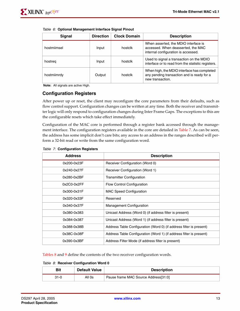
Configuration of the MAC core is performed through a register bank accessed through the manage-ment interface. The configuration registers available in the core are detailed in Table 7. As can be seen,the address has some implicit don’t care bits; any access to an address in the ranges described will per-form a 32-bit read or write from the same configuration word.
Figure Top x-ref 10Register Maps
Tables 8 and 9 define the contents of the two receiver configuration words.
hostmiimsel Input hostclkWhen asserted, the MDIO interface is accessed. When deasserted, the MAC internal configuration is accessed.
hostreq Input hostclkUsed to signal a transaction on the MDIO interface or to read from the statistic registers.
hostmiimrdy Output hostclkWhen high, the MDIO interface has completed any pending transaction and is ready for a new transaction.
Note: All signals are active High.
Table 7: Configuration Registers
Address Description
0x200-0x23F Receiver Configuration (Word 0)
0x240-0x27F Receiver Configuration (Word 1)
0x280-0x2BF Transmitter Configuration
0x2C0-0x2FF Flow Control Configuration
0x300-0x31F MAC Speed Configuration
0x320-0x33F Reserved
0x340-0x37F Management Configuration
0x380-0x383 Unicast Address (Word 0) (if address filter is present)
0x384-0x387 Unicast Address (Word 1) (if address filter is present)
Table 12 defines the register contents for the Management Configuration Word.
Table 13 defines the register contents for the MAC Speed Configuration Word.
The address filter can be programmed to respond to up to 5 user-defined addresses. These can be storedin a dedicated unicast address register and, if the Management Interface is present, in a n-address deeptable, where n can be in the range 0 to 4. In addition, the broadcast and pause multicast addressesdefined in the IEEE802.3-2002 and the pause frame MAC source address (Tables 8 and 9) are also rec-ognized. The register contents for the two unicast address registers are described in Tables 14 and 15.
Tables 16 and 17 show how the contents of the address table are set.
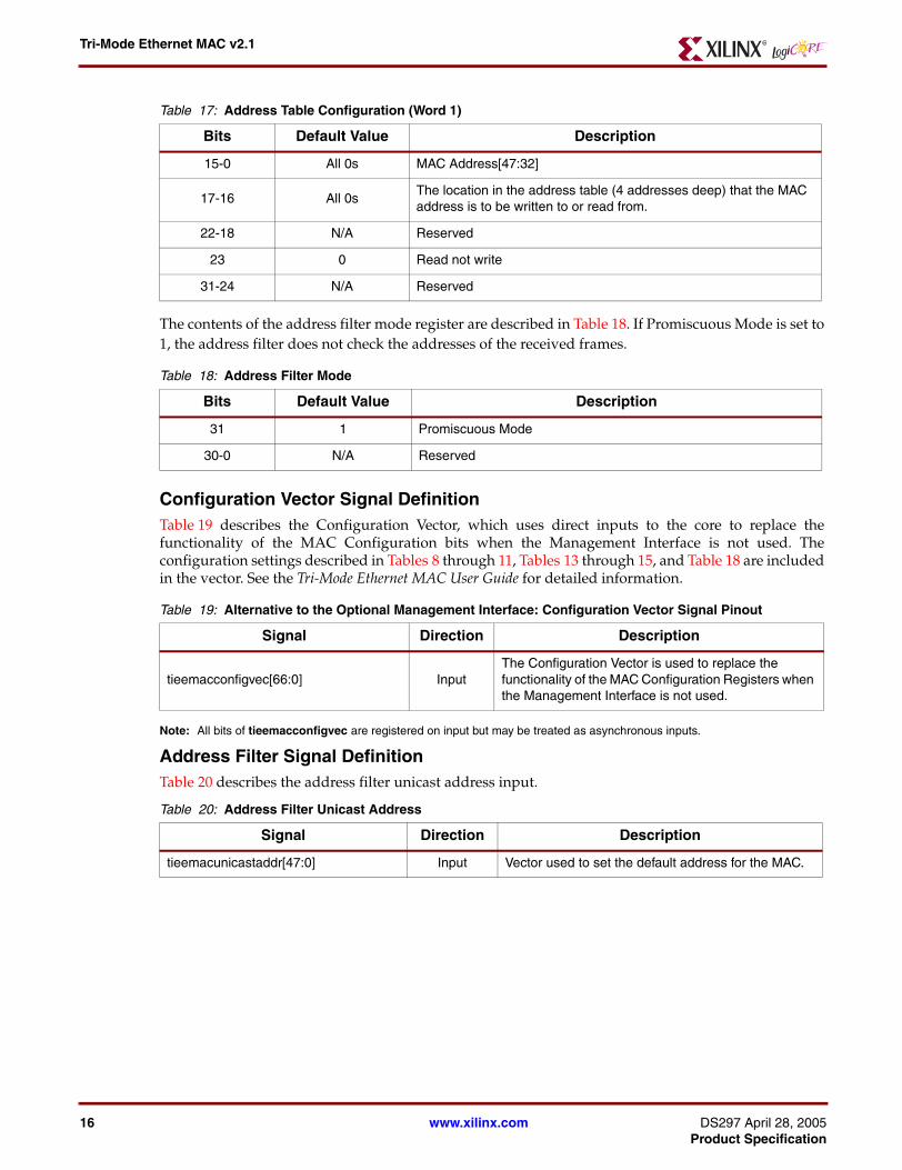
The contents of the address filter mode register are described in Table 18. If Promiscuous Mode is set to1, the address filter does not check the addresses of the received frames.
Configuration Vector Signal DefinitionTable 19 describes the Configuration Vector, which uses direct inputs to the core to replace thefunctionality of the MAC Configuration bits when the Management Interface is not used. Theconfiguration settings described in Tables 8 through 11, Tables 13 through 15, and Table 18 are includedin the vector. See the Tri-Mode Ethernet MAC User Guide for detailed information.
Note: All bits of tieemacconfigvec are registered on input but may be treated as asynchronous inputs.
Address Filter Signal DefinitionTable 20 describes the address filter unicast address input.
Table 17: Address Table Configuration (Word 1)
Bits Default Value Description
15-0 All 0s MAC Address[47:32]
17-16 All 0sThe location in the address table (4 addresses deep) that the MAC address is to be written to or read from.
22-18 N/A Reserved
23 0 Read not write
31-24 N/A Reserved
Table 18: Address Filter Mode
Bits Default Value Description
31 1 Promiscuous Mode
30-0 N/A Reserved
Table 19: Alternative to the Optional Management Interface: Configuration Vector Signal Pinout
Signal Direction Description
tieemacconfigvec[66:0] InputThe Configuration Vector is used to replace the functionality of the MAC Configuration Registers when the Management Interface is not used.
Table 20: Address Filter Unicast Address
Signal Direction Description
tieemacunicastaddr[47:0] Input Vector used to set the default address for the MAC.
www.xilinx.com DS297 April 28, 2005Product Specification
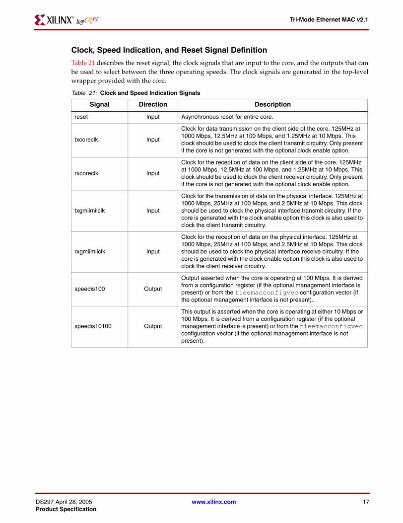
Clock, Speed Indication, and Reset Signal Definition
Table 21 describes the reset signal, the clock signals that are input to the core, and the outputs that canbe used to select between the three operating speeds. The clock signals are generated in the top-levelwrapper provided with the core.
Table 21: Clock and Speed Indication Signals
Signal Direction Description
reset Input Asynchronous reset for entire core.
txcoreclk Input
Clock for data transmission on the client side of the core. 125MHz at 1000 Mbps, 12.5MHz at 100 Mbps, and 1.25MHz at 10 Mbps. This clock should be used to clock the client transmit circuitry. Only present if the core is not generated with the optional clock enable option.
rxcoreclk Input
Clock for the reception of data on the client side of the core. 125MHz at 1000 Mbps, 12.5MHz at 100 Mbps, and 1.25MHz at 10 Mbps. This clock should be used to clock the client receiver circuitry. Only present if the core is not generated with the optional clock enable option.
txgmiimiiclk Input
Clock for the transmission of data on the physical interface. 125MHz at 1000 Mbps, 25MHz at 100 Mbps, and 2.5MHz at 10 Mbps. This clock should be used to clock the physical interface transmit circuitry. If the core is generated with the clock enable option this clock is also used to clock the client transmit circuitry.
rxgmiimiiclk Input
Clock for the reception of data on the physical interface. 125MHz at 1000 Mbps, 25MHz at 100 Mbps, and 2.5MHz at 10 Mbps. This clock should be used to clock the physical interface receive circuitry. If the core is generated with the clock enable option this clock is also used to clock the client receiver circuitry.
speedis100 Output
Output asserted when the core is operating at 100 Mbps. It is derived from a configuration register (if the optional management interface is present) or from the tieemacconfigvec configuration vector (if the optional management interface is not present).
speedis10100 Output
This output is asserted when the core is operating at either 10 Mbps or 100 Mbps. It is derived from a configuration register (if the optional management interface is present) or from the tieemacconfigvec configuration vector (if the optional management interface is not present).
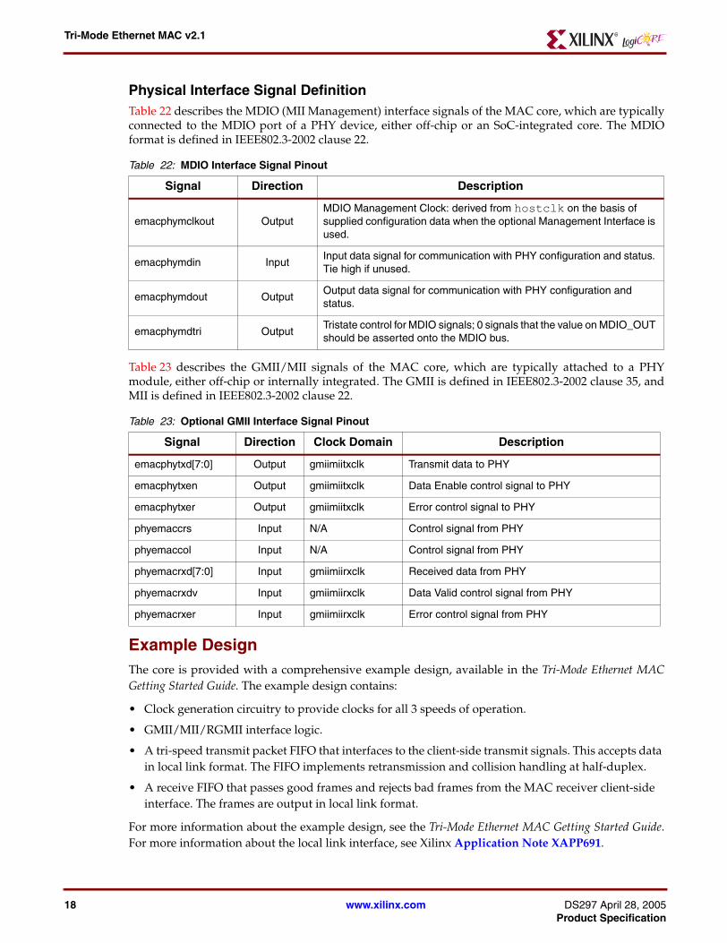
Physical Interface Signal DefinitionTable 22 describes the MDIO (MII Management) interface signals of the MAC core, which are typicallyconnected to the MDIO port of a PHY device, either off-chip or an SoC-integrated core. The MDIOformat is defined in IEEE802.3-2002 clause 22.
Table 23 describes the GMII/MII signals of the MAC core, which are typically attached to a PHYmodule, either off-chip or internally integrated. The GMII is defined in IEEE802.3-2002 clause 35, andMII is defined in IEEE802.3-2002 clause 22.
Example DesignThe core is provided with a comprehensive example design, available in the Tri-Mode Ethernet MACGetting Started Guide. The example design contains:
• Clock generation circuitry to provide clocks for all 3 speeds of operation.
• GMII/MII/RGMII interface logic.
• A tri-speed transmit packet FIFO that interfaces to the client-side transmit signals. This accepts data in local link format. The FIFO implements retransmission and collision handling at half-duplex.
• A receive FIFO that passes good frames and rejects bad frames from the MAC receiver client-side interface. The frames are output in local link format.
For more information about the example design, see the Tri-Mode Ethernet MAC Getting Started Guide.For more information about the local link interface, see Xilinx Application Note XAPP691.
Table 22: MDIO Interface Signal Pinout
Signal Direction Description
emacphymclkout OutputMDIO Management Clock: derived from hostclk on the basis of supplied configuration data when the optional Management Interface is used.
emacphymdin InputInput data signal for communication with PHY configuration and status. Tie high if unused.
emacphymdout OutputOutput data signal for communication with PHY configuration and status.
emacphymdtri OutputTristate control for MDIO signals; 0 signals that the value on MDIO_OUT should be asserted onto the MDIO bus.
Table 23: Optional GMII Interface Signal Pinout
Signal Direction Clock Domain Description
emacphytxd[7:0] Output gmiimiitxclk Transmit data to PHY
emacphytxen Output gmiimiitxclk Data Enable control signal to PHY
emacphytxer Output gmiimiitxclk Error control signal to PHY
phyemaccrs Input N/A Control signal from PHY
phyemaccol Input N/A Control signal from PHY
phyemacrxd[7:0] Input gmiimiirxclk Received data from PHY
phyemacrxdv Input gmiimiirxclk Data Valid control signal from PHY
phyemacrxer Input gmiimiirxclk Error control signal from PHY
www.xilinx.com DS297 April 28, 2005Product Specification
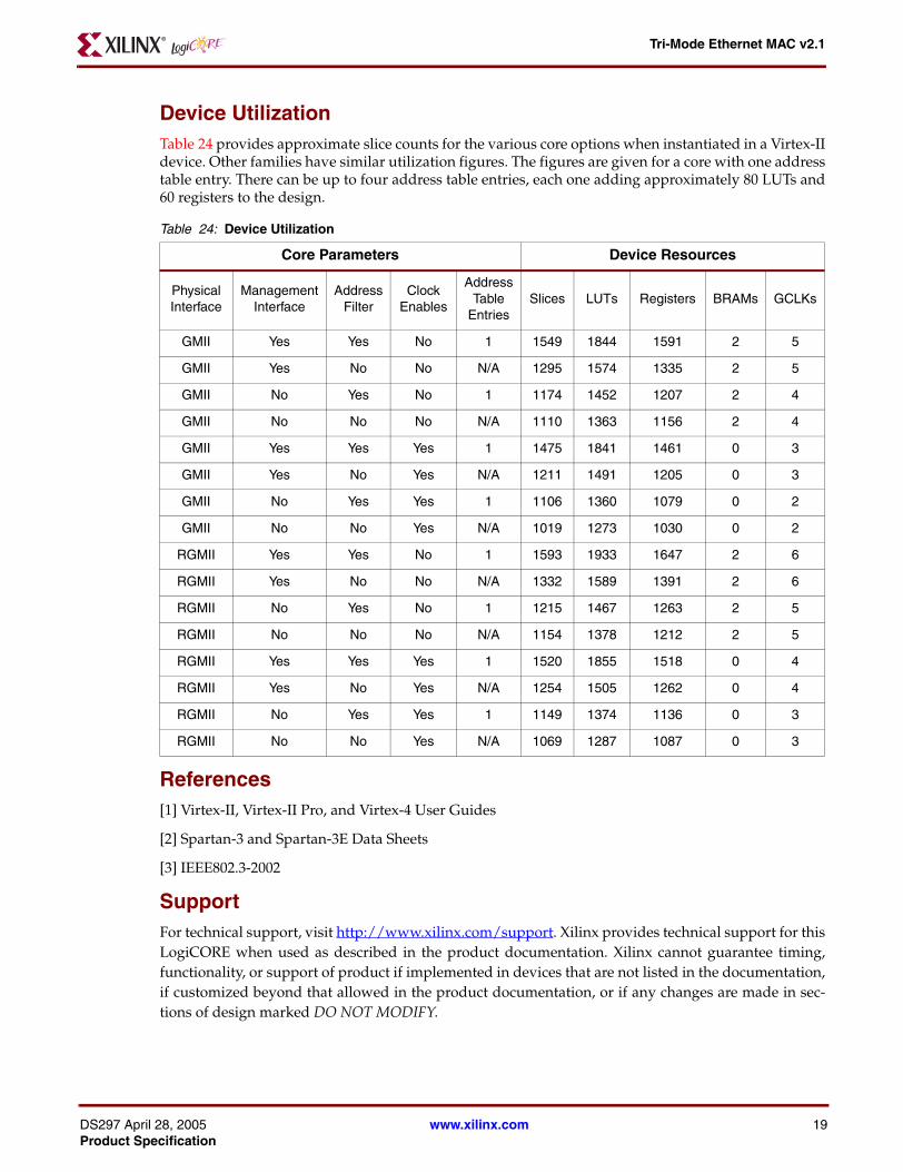
Device UtilizationTable 24 provides approximate slice counts for the various core options when instantiated in a Virtex-IIdevice. Other families have similar utilization figures. The figures are given for a core with one addresstable entry. There can be up to four address table entries, each one adding approximately 80 LUTs and60 registers to the design.
References[1] Virtex-II, Virtex-II Pro, and Virtex-4 User Guides
[2] Spartan-3 and Spartan-3E Data Sheets
[3] IEEE802.3-2002
SupportFor technical support, visit http://www.xilinx.com/support. Xilinx provides technical support for thisLogiCORE when used as described in the product documentation. Xilinx cannot guarantee timing,functionality, or support of product if implemented in devices that are not listed in the documentation,if customized beyond that allowed in the product documentation, or if any changes are made in sec-tions of design marked DO NOT MODIFY.
Ordering InformationThis Xilinx LogiCORE module is provided under the SignOnce IP Site License. Two free evaluationlicenses are provided: The Simulation Only license is provided by default with the CORE Generator,and the Full System Hardware license, which lets you test your designs in hardware for a limitedperiod of time, can be downloaded from the TEAMC product page.
For full access to all core functionality, both in simulation and in hardware, you must purchase the core.After purchase, the core may be downloaded from the Xilinx IP Center for use with the Xilinx COREGenerator System v7.1i and later. The Xilinx CORE Generator system is bundled with the Xilinx ISEFoundation v7.1i software at no additional charge.
Please contact your local Xilinx sales representative or visit the Xilinx Silicon Xpresso Cafe for pricingand availability on Xilinx LogiCORE modules and software. Information about additional Xilinx Logi-CORE modules is available on the Xilinx IP Center.
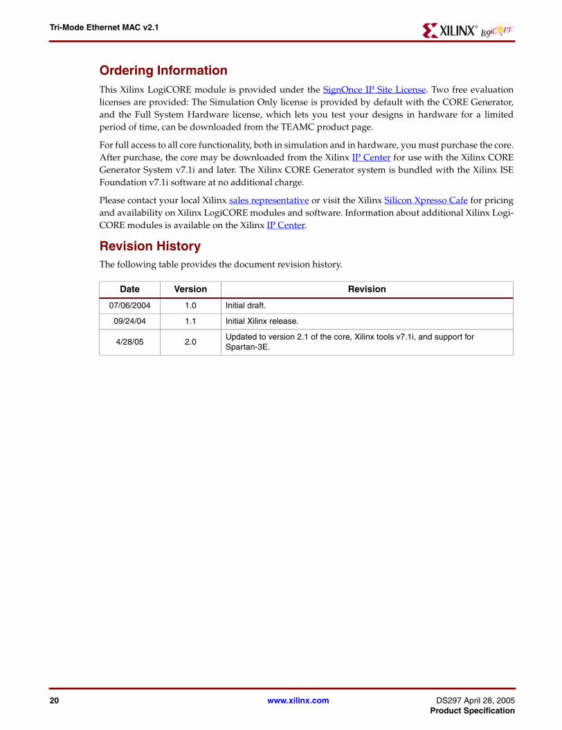
Revision History
The following table provides the document revision history.
Date Version Revision
07/06/2004 1.0 Initial draft.
09/24/04 1.1 Initial Xilinx release.
4/28/05 2.0Updated to version 2.1 of the core, Xilinx tools v7.1i, and support for Spartan-3E.
www.xilinx.com DS297 April 28, 2005Product Specification