STATE OF CALIFORNIA • ARNOLD SCHWARZENEGGER, GOVERNOR STATE AND CONSUMER SERVICES AGENCY • DEPARTMENT OF GENERAL SERVICES INTERPRETATION OF REGULATIONS Division of the State Architect The DSA “IR” Manual Acceptable methods of achieving compliance with applicable building codes and regulations for projects under the jurisdiction of DSA. Revised 1-02-08
Transcript
ST AT E OF C AL I FORNI A • AR NOLD SCH W AR ZENEGGER , GOVERNOR S T AT E AN D C O N S UM E R S E R V I C E S AG E N C Y • D E P AR T M E N T O F G E N E R AL S E R V I C E S
INTERPRETATION OF
REGULATIONS
Division of the State Architect
The DSA “IR” ManualAcceptable methods of achieving compliance with
applicable building codes and regulationsfor projects under the jurisdiction of DSA.
DDSSAA IInntteerrpprreettaattiioonn ooff RReegguullaattiioonnss MMaannuuaall Introduction Welcome to the Division of the St hitect (DSA) Interpretation of Regulations (IR) Manual. These interpretations have been developed over many years made as necessary to update thereferred to as the California Buildin
The IR Manual was created for applicable building codes and remonitoring of construction of pubproposed by design professionalregulation compliance.
These interpretations are neither inclusion in project specifications.specific requirements for each pro
Please note that the IR Manual ca Should you have any questions aaddress your questions or comme If you have questions regarding thDSA Regional Office. Four RegionTo find out which office serves you
The DSA Regional Offices can be
Los Angeles Basin Regional Off700 North Alameda St., Suite 5-50Los Angeles, CA 90012 Tel. (213) 897-3995 Fax (213) 897-3159 or (213) 897-0
San Francisco Bay Area Region1515 Clay Street, Suite 1201 Oakland, CA 90012 Tel. (510) 622-3101 Fax (510) 622-3140
ate Arc
ulations Manual Page ii
and were first assembled under one cover in 1984. Additions, deletions and changes are interpretations to the latest edition of the California Code of Regulations, Title 24, also g Standards Code.
use by DSA as a documentation of acceptable methods for achieving compliance with gulations. Its purpose is to promote more uniform statewide criteria in plan review and lic school, community college and essential services building projects. Other methods s to solve a particular issue may be considered by DSA and reviewed for code and
regulations nor law. The text and drawings in this manual are not appropriate for verbatim The design professional in responsible charge is responsible for specifying and detailing ject.
n be accessed on the “Publications” page of the DSA web site at: www.dsa.dgs.ca.gov
bout the IR Manual, or wish to offer comments toward improving this publication, please nts to: [email protected]
e application of an IR to a specific project, please direct those questions directly to your al Offices are located to serve California based on the county in which a project is located. r location, go to: http://www.dsa.dgs.ca.gov/contact
contacted as follows:
ice San Diego Regional Office 0 16680 West Bernardo Drive
San Diego, CA 92127 Tel. (858) 674-5400
726 Fax (858) 674-5471
al Office Sacramento Regional Office 1102 Q Street, Suite 5100 Sacramento, CA 95811-6550 Tel. (916) 445-8730 Fax (916) 323-5589
Organization of the IR Manual This manual is organized so IR’s can be located by reference to their location in the California Code of Regulations, Title 24, also referred to as the California Building Standards Code. Title 24 is issued in twelve volumes, called “Parts.” DSA IR numbers have a letter prefix to designate the correct Part in Title 24. All IR’s carry this prefix letter, except those from Part 2, the California Building Code (CBC). Since Part 2 IR’s are so numerous, Part 2 IR numbers contain their Part 2 chapter number instead of a prefix letter. No prefix letters have been assigned at this time for Parts 7, 8, 10, 11 and 12. The following list should serve as an aid to understanding this organization: Title 24 Code Prefix Part# Title letter 1 California Buildings Standards Administrative Code (CAC) .............. A 2 California Building Code (CBC) ................................................... -- 3 California Electrical Code (CEC)................................................... E 4 California Mechanical Code (CMC)................................................ M 5 California Plumbing Code (CPC)................................................... P 6 California Energy Code .............................................................. N 7 Elevator Operation Code ............................................................ -- 8 Historical ................................................................................. -- 9 Fire......................................................................................... F 10 Conservation............................................................................ -- 11 (reserved) ............................................................................... -- 12 Reference ................................................................................ -- IR’s that have been revised since August of 2002 may include marginal markings. Solid vertical lines in the margins within the body of the IR indicate a change from the previously published IR, except where a change was minor or editorial. An arrow is provided in the margin to indicate that a deletion has been made from the previously published version. As IR’s are added, deleted or revised, the changes will be reflected in the on-line version of the IR -Manual. This publication is available for download or printing (in whole or in part) as Adobe PDF format files on the “Publications” page of the DSA web site at www.dsa.dgs.ca.gov. When referencing IR’s, the user can ensure he or she is using the latest version by checking the on-line IR Manual. Change of California Building Code On January 1, 2008, the 2007 CBC will take effect for projects under the jurisdiction of DSA. This new edition of the California Building Code is based on a new model code: the 2006 IBC. This means the new code is significantly different from the 2001 CBC. Most California amendments have moved to new locations in the new code. All projects submitted to DSA after January 1, 2008 will be governed by the 2007 CBC. As a result of these changes, some IR’s may become unnecessary if their provisions are part of a new model code or have been incorporated into new California amendments. Other IR’s may be modified and still others may remain unaffected. Changes have been made to the Table of Contents page to more easily indicate which IR’s are applicable to which CBC version and to facilitate navigation. Applicability of IR’s to projects submitted under the 2001 CBC or the 2007 CBC is indicated in the last 2 columns. “N/A” indicates that the IR is not applicable to projects submitted to DSA under that edition of the California Building Code.
DSA IR Manual - Table of Contents DSA IR Manual - Table of Contents Revised 01-02-08 (previous/ issued/ 2001 2007 # Title supercedes) revised CBC CBC
DSA Interpretation of Regulations Manual Page iv
Part 1 - ADMINISTRATIVE A-1 Temporary Approval for School Use of (PL 97-10) 09-06-07 (r) X X HCD Commercial Coaches
A-2 Certificate of Compliance without Receipt of All Documents 09-01-99 (r) X
A-3 Construction Management Procedures for Public School Projects 09-01-99 (r) X
A-4 Geological Hazard Report Requirements 11-01-07 (r) X X
A-5 Acceptance of Evaluation Reports 07-21-05 (r) X
A-6 Change Order and Field Change Approval Process 09-18-07 (r) X X
A-7 Project Inspector Certification and Approval 09-18-07 (r) X X
A-8 Project Inspector and Assistant Inspector Duties and Performance 10-03-07 (r) X X
A-9 School Site Improvements for School Building Projects 04-21-05 (r) X A-10 Reconstruction and Alteration Projects - 05-29-07 (r) X X Exemption from DSA Approval A-11 Incremental Submittals 12-08-05 X A-12 Assistant Inspector Approval 10-03-07 (r) X X
A-13 Stop Work and Order to Comply 04-05-07 X X
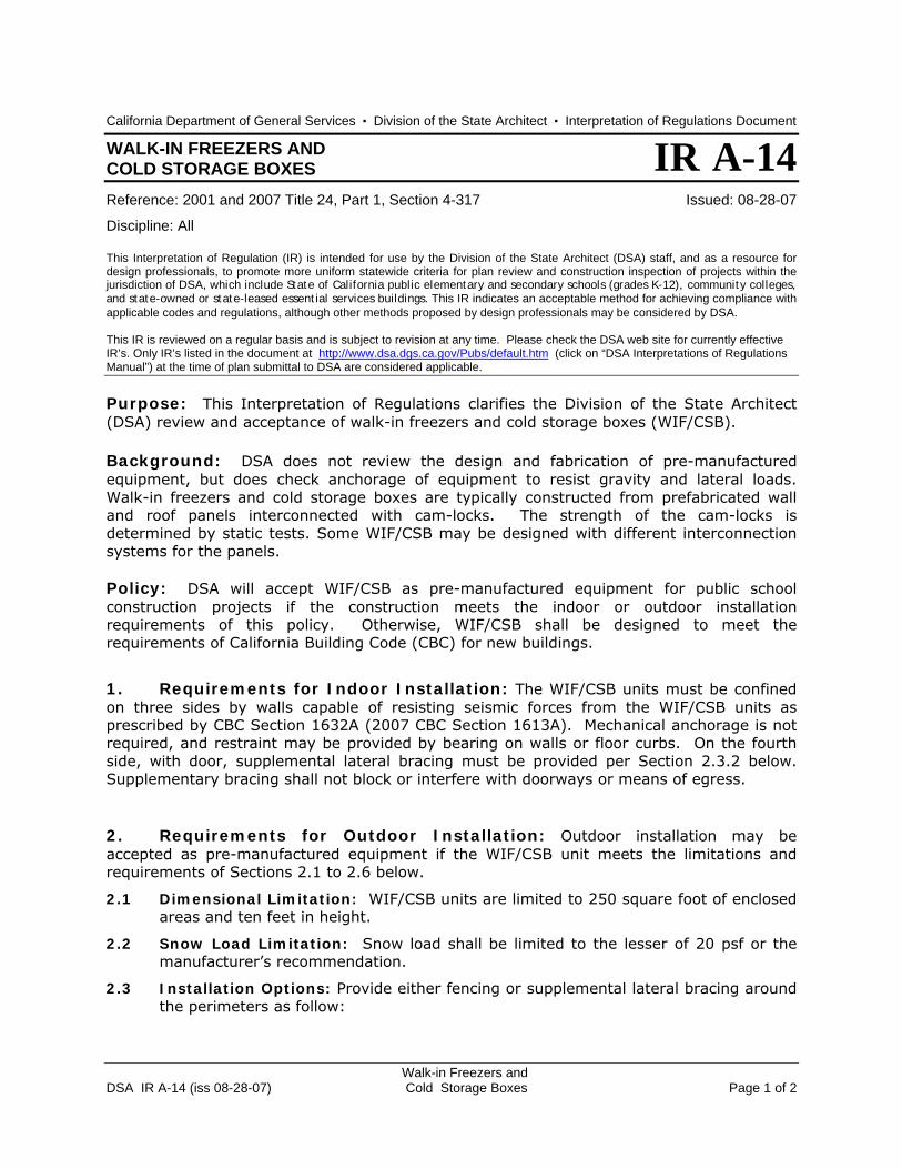
A-14 Walk In Freezers and Cold Storage Boxes 08-28-07 X X
A-15 Testing and Inspection of Remotely Fabricated Elements (CR A-1) 10-15-07 (r) X X
A-16 Charter School Enforcement Jurisdiction (PL 94-19) 11-01-07 X X
Part 2, Chapter 3 - USE OR OCCUPANCY 3-1 Storage Room Occupancy Separation 09-18-07 (r) X N/A
Part 2, Chapter 9 – FIRE PROTECTION SYSTEMS 9-1 Automatic Fire Suppression System Coverage in Concealed Interstitial Spaces 10-15-07 (r) X X
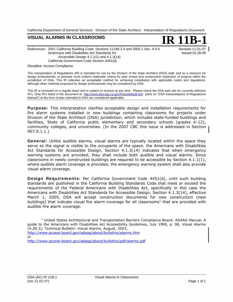
Part 2, Chapter 11B - ACCESS 11B-1 Visual Alarms in Classrooms 11-01-07 (r) X N/A
11B-2 Beveled Lip at Curb Ramps 11-01-07 (r) X N/A
11B-3 Detectable Warnings at Curb Ramps 11-01-07 (r) X N/A
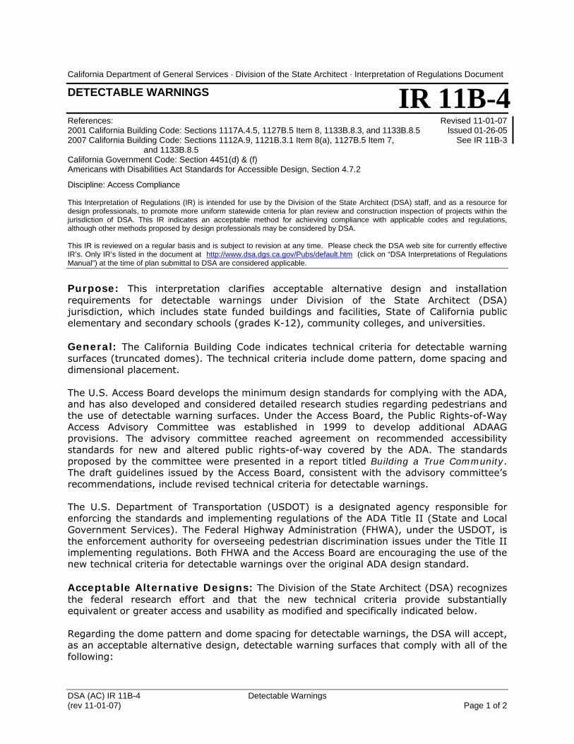
11B-4 Detectable Warnings 11-01-07 (r) X X
11B-5 Effort to Operate Exterior Doors 11-01-07 (r) X X
Part 2, Chapter 15 - ROOFING AND ROOF STRUCTURES 15-1 Attachment of Clay or Concrete “S” Roof Tile 10-15-07 (r) X X
15-2 Clay and Concrete Roof Tile Materials and Application 10-15-07 X X
Part 2, Chapter 16 - STRUCTURAL DESIGN 16-1 Conditional Certification for Relocatable School Buildings 09-10-02 (r) X
16-2 Computer or Office Access Floors 01-02-08 (r) X N/A
16-3 Earth Retaining Systems 09-18-07 (r) X X
16-4 Wind Load Design for One Story Relocatable School 01-02-08 (r) X N/A Buildings (Less than 2000 Square Feet in Floor Area)
16-5 Design and Construction of Reviewing Stands, Grandstands, 04-21-05 (r) X and Bleachers
DSA IR Manual - Table of Contents DSA IR Manual - Table of Contents Revised 01-02-08 (previous/ issued/ 2001 2007 # Title supercedes) revised CBC CBC
DSA Interpretation of Regulations Manual Page v
16-6 Composite Base for HVAC Units (CR 16-1) 10-15-07 (r) X X
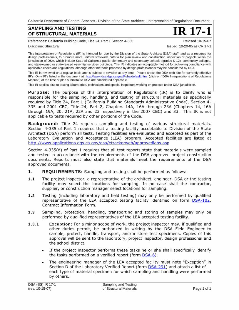
16-7 Wind Load Determination - Alternate Method 12-18-07 N/A X Part 2, Chapter 17 – Structural Tests and Special Inspections 17-1 Sampling and Testing of Structural Materials (CR 17-1) 10-15-07 (r) X X
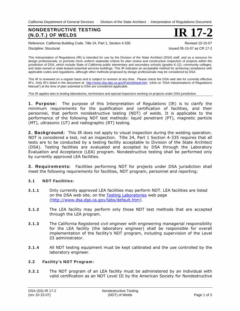
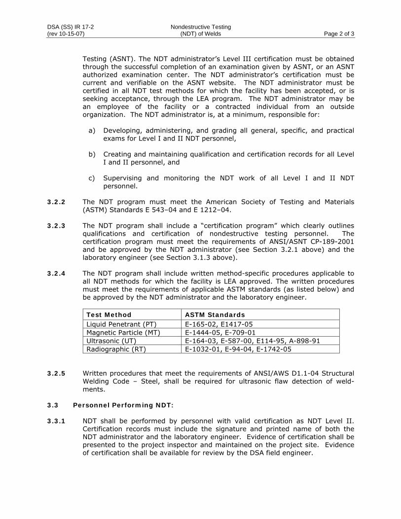
17-2 Nondestructive Testing (NDT) of Welds (CR 17-2) 10-15-07 (r) X X
17-3 Structural Welding Inspection (CR 17-3) 01-02-08 (r) X N/A
Part 2, Chapter 19 - CONCRETE 19-1 Post Installed Anchors in Concrete 03-06-06 (r) X
19-2 Requirements for Glass Fiber Reinforced Concrete (GFRC) Panels 09-01-99 (r) X
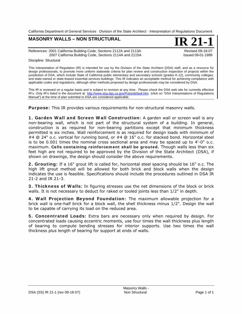
Part 2, Chapter 21 - MASONRY 21-1 Masonry Walls – Non Structural 09-18-07 (r) X X
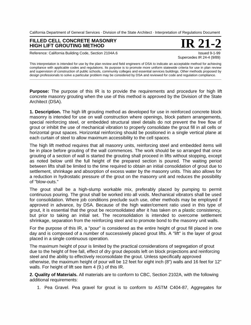
21-2 Filled Cell Concrete Masonry High Lift Grouting Method 09-01-99 (r) X
21-3 Clay Brick Masonry High Lift Grouting Method 09-01-99 (r) X
21-4 Concrete Masonry Units Standards (CR 21-1) 11-01-07 (r) X X
Part 2, Chapter 22 - STEEL
22-1 Design Procedure for Steel Deck Diaphragms 01-02-08 (r) X X With Structural Concrete Fill
22-2 Anchor Bolts Connecting Steel to Concrete (CR 22-1) 11-01-07 (r) X X
Part 2, Chapter 23 - WOOD 23-1 Pre-fabricated Wood Construction Connectors 11-01-07 (r) X X
23-2 Wood Diaphragms 11-01-07 (r) X N/A
23-3 Concrete Curbs in Wood Frame Buildings 10-03-07 (r) X X
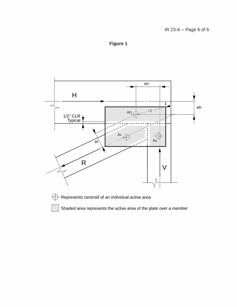
23-4 Light Metal Plate Connected Wood Trusses 11-01-07 (r) X N/A
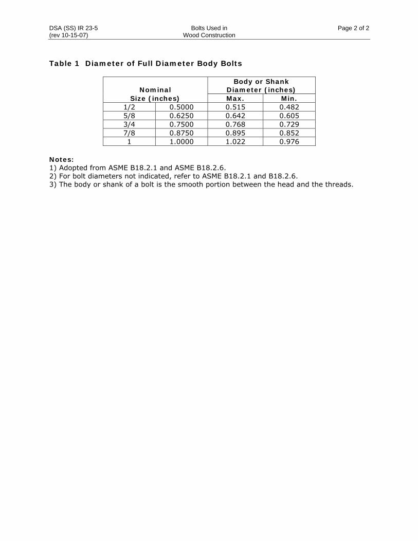
23-5 Bolts Used in Wood Construction (CR 23-1) 10-15-07 (r) X X
23-6 Wood Structural Panels – Plywood Panel Marking (CR 23-2) 10-15-07 (r) X X
23-7 Minimum Fastener Penetration in Framing (CR 23-3) 11-01-07 (r) X N/A – Wood Diaphragms
Part 2, Chapter 24 - GLASS AND GLAZING 24-1 Glass Panel Railings 01-02-08 (r) X X
Part 2, Chapter 15 - GYPSUM BOARD AND PLASTER 25-1 Maximum Allowable Load for 10 Gage & 12 Gage Wires 09-18-07 (r) X X
25-2 Metal Suspension Systems for Lay-In Panel Ceilings 07-21-05 (r) X
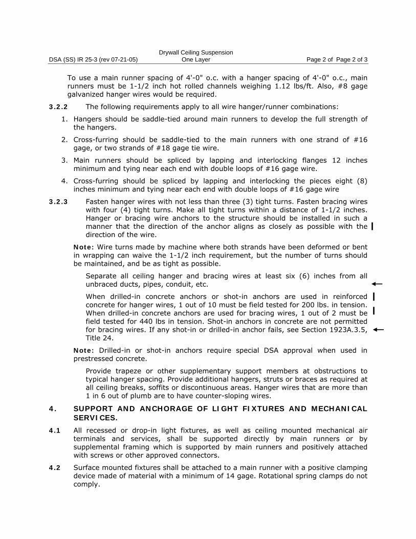
25-3 Drywall Ceiling Suspension Conventional Construction: One Layer 07-21-05 (r) X
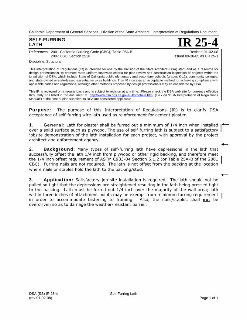
25-4 Self-Furring Lath (CR 25-1) 01-02-08 (r) X X
Part 3 - ELECTRICAL E-1 Grounding of Relocatable Buildings 10-03-07 (r) X X
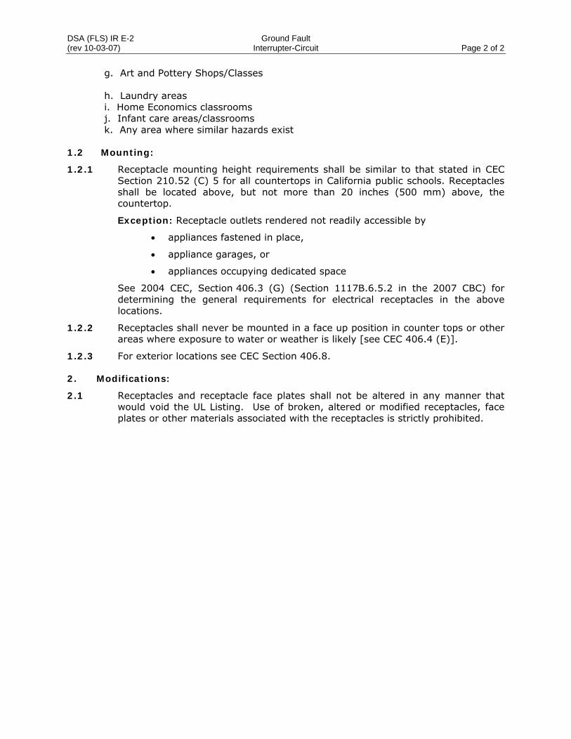
E-2 Ground Fault Circuit-Interrupter 10-03-07 (r) X X
DSA IR A-1 (iss 09-06-07) Temporary Approval for School EFFECTIVE 10-01-07 Use of HCD Commercial Coaches Page 1 of 5
California Department of General Services . Division of the State Architect . Interpretation of Regulations Document
TEMPORARY APPROVAL FOR SCHOOL USE OF HCD COMMERCIAL COACHES References: Issued 09-06-2007 California Building Code, Title 24, Pt.1, Sections 4-302B, 4-321 EFFECTIVE: 10-01-07 California Education Code, Sections 17280-17317, 81130-81149 Supersedes DSA Policy 97-10 California Government Code, Sections 4450-4461 Discipline: ALL This Interpretation of Regulation (IR) is intended for use by the Division of the State Architect (DSA) staff, and as a resource for design professionals, to promote more uniform statewide criteria for plan review and construction inspection of projects within the jurisdiction of DSA, which include State of California public elementary and secondary schools (grades K-12), community colleges, and state-owned or state-leased essential services buildings. This IR indicates an acceptable method for achieving compliance with applicable codes and regulations, although other methods proposed by design professionals may be considered by DSA. This IR is reviewed on a regular basis and is subject to revision at any time. Please check the DSA web site for currently effective IR’s. Only IR’s listed in the document at http://www.dsa.dgs.ca.gov/Pubs/default.htm (click on “DSA Interpretations of Regulations Manual”) at the time of plan submittal to DSA are considered applicable. Purpose: This Interpretation of Regulation (IR) was originally issued in 1997 as DSA Policy #97-10. The purpose of this IR is to provide a means for obtaining a temporary approval for the installation of Department of Housing & Community Development (HCD) commercial coaches as buildings on public school campuses. Temporary approval is valid for a maximum period of two years from the date of installation. If an unanticipated school use need for the building(s) exceeds two years, DSA shall be notified and may extend the temporary approval for one additional year. This IR provides for temporary approval to use HCD commercial coaches without DSA review and approval of the structural system of the HCD building itself. This revision eliminates the self certification features of the previous procedure. Background: HCD commercial coaches may be used as a building construction alternative when fully conforming relocatable buildings are not practical or available. In accordance with Section 4-302(b), Part 1, Title 24, California Code of Regulations, this DSA IR provides an expedited process for school districts to use for Division of the State Architect (DSA) approval of small relocatable buildings. The school district is highly encouraged to contact DSA immediately if there is intent to install temporary buildings using this expedited process. Emergency Use: In case of emergencies, including but not limited to damage to school buildings as from earthquakes, fires and floods, or for health and safety issues such as mold or other contamination, or from unanticipated increase in students wherein educational facilities are immediately needed for displaced or unhoused pupils, the procedure detailed in this IR permits placement of the HCD temporary use building in advance of securing DSA temporary approval. This emergency use procedure may also be used for emergency installation of DSA Pre-Checked relocatable buildings. DSA must be notified immediately after the emergency of the district’s intent to use this emergency use IR. Within 14 days following the installation of these emergency temporary use buildings, the school district will notify DSA of the extent of the damage to their permanent school
IR A-1
DSA IR A-1 (iss 09-06-07) Temporary Approval for School EFFECTIVE 10-01-07 Use of HCD Commercial Coaches Page 2 of 5 buildings and the number of temporary buildings installed to house displaced students. Within 60 days following installation of these emergency temporary use buildings, the design professional representing the school district shall provide DSA with a complete submittal package as described in this procedure. Use During Modernization Projects: School use of HCD temporary approved buildings during modernization projects would require DSA review and approval and receipt of a temporary approval per this procedure prior to placement. The emergency use procedures of this IR may be used when, during the modernization project, there is an unanticipated immediate need for a building for displaced or unhoused students. Submittal: The school district shall provide the following to the Division of the State Architect (DSA) Regional Office serving its area: 1. DSA-1 – Application for Temporary Approval of Plans and Specifications: Fill in completely form DSA-1. To describe the project - on line 5 of form DSA-1 write “temporary approval for school use of __ HCD commercial coaches”. For example line 5 would read “Construction of: temporary approval for school use of 2 HCD commercial coaches” if two buildings are being installed. 2. Fee: The school district will submit fees with the initial application per Fee Schedule II, Section 4-321, Part 1, Title 24 and per Section 5-104, Part 1, Title 24 for access compliance review. For purposes of calculating the fee, the construction cost should be based on the cost of any site work, improvements to the building and/or repairs and the costs for moving the building. 3. Letter: A letter from the school district (Superintendent) acknowledging that these buildings are only for temporary use and are limited to use for 24 months from the date of installation. 4. Plans, Specifications and Calculations: shall be provided, including the following:
Note: Plans, specifications and calculations for the HCD building are not required if the HCD building is certified per Section 5 and a letter is provided, from the architect/engineer in responsible charge, stating that the building has not had alterations, or suffered deterioration, that affect access compliance, structural safety or fire/life safety code regulated elements. For example; addition of wall supported casework is an alteration to the building. If altered, complete plans, specifications and calculations, as needed for the altered portion of the building, shall be submitted for review and approval. Maintenance work does not need to be included in the submittal. See the definition of “maintenance” in Section 4-314, Part 1 of Title 24, California Code of Regulations.
4.1 Cover Sheet of Plans: Add a note stating that these buildings are only for temporary use and are limited to use for 24 months from the date of installation.
4.2 Structural Safety (SS): Submitted plans, specifications and calculations shall indicate the following:
4.2.1 Floor Area: The building is one story and has a floor area of no more than 2,160 square feet. The floor area shall be shown on the drawings. A drawing showing the footprint of the building, except as noted in this IR, is generally adequate for the HCD building.
DSA IR A-1 (iss 09-06-07) Temporary Approval for School EFFECTIVE 10-01-07 Use of HCD Commercial Coaches Page 3 of 5 4.2.2 Foundation System: Complete plans specifications and calculations for the
anchorage and bracing of the building in accordance with the current California Building Code (CBC) through December 31, 2007; after this date foundation designs shall be in accordance with the 2007 CBC. Foundation system plans could receive DSA pre-check (PC) approval (see DSA Policy 07-01), and be submitted over-the-counter (OTC), with DSA Regional Office coordination. Some foundation systems may require soils reports and/or soil testing and anchorage system testing. For first time foundation system submittals, presubmittal coordination with the local regional office is highly encouraged.
4.2.3 Non Structural Elements: Plans and specifications shall detail the anchorage of all overhead non-structural elements, labeled as existing or new, as appropriate.
4.3 Access Compliance (AC): The construction must comply with all Access Compliance regulations. No alternatives are available. A complete submittal shall include but is not limited to the following;
4.3.1 For exterior construction: Complete plans and specifications of the disabled access features of the site placement for the HCD building, including:
• An accessible pedestrian route from the main entrance of the site to each commercial coach and linking accessibility elements.
• A code compliant ramp to the front door of the building;
• At least one hi-lo drinking fountain centrally located.
• At least one set of accessible separate sex toilet facilities centrally located and available for use.
• Van-accessible parking.
4.3.2 For interior construction: Code required accessibility features for the HCD building itself shall be provided. For example:
• Accessible lever door hardware and threshold provided at the entrance door of each commercial coach with allowable closer pressure.
• Toilets, or any other code regulated accessibility features inside the HCD
building, must be fully detailed on the plans. 4.4 Fire and Life Safety (FLS): Complete and accurate plans, specifications and
calculations shall be submitted as follows:
4.4.1 A site plan must be submitted with the stamp and signature of the local fire authority indicating approval of the placement of the buildings, the fire apparatus access road and access gates and water flow and hydrants.
4.4.2 Separation distances, and designated safe dispersal area or areas conform to Fire and Life Safety code requirements. The path or paths of egress to the public way or to the safe dispersal area(s) has/have been identified and shown on the site plans, and all gates in the path(s) of egress have been identified and equipped with panic hardware. Safe dispersal area(s) has/have been located, size and occupant loads identified, and the dimensions from buildings clearly indicated (minimum 50’) on the site plan.
DSA IR A-1 (iss 09-06-07) Temporary Approval for School EFFECTIVE 10-01-07 Use of HCD Commercial Coaches Page 4 of 5 4.4.3 Provide an evacuation fire alarm system consisting, as a minimum, of an
approved manual pull-station and audible device(s) (with a minimum decibel rating of 95 at 10 feet) powered by the building’s electrical system (backup battery power) and building units more than twenty (20) feet apart are provided with additional audible devices to ensure fire alarm can be heard within adjacent buildings.
4.4.4 Units more than 20 feet from other buildings, including other temporary buildings, with a stand alone fire alarm system must be provided with “two-way communication” with the main administration offices via an intercom system, permanently mounted telephone or “walkie-talkie” devises or other similar systems. Buildings that are less than twenty (20) feet from existing permanent buildings on the site shall be interconnected with the fire alarm system of the campus.
4.4.5 Each HCD building must be equipped with at least one minimum rated 2A:10B: C fire extinguisher, mounted at 48 inches to the handle above the finished floor, near the main exist(s) and within 75 foot travel distance from any point within the building. (Note: “Travel distance” shall not include paths through normally locked doors.)
5. DSA Approval of Plan and specifications: DSA will review the submitted documents. The documents will be returned to the design professional noted on the application to respond to comments. The design professional shall contact DSA to schedule a backcheck appointment. Once all the comments have been addressed, DSA will initial and date the DSA stamp on the drawings and provide a letter by e-mail approving the design of the project for temporary two year use. In some circumstances the over-the-counter (OTC) process may be used (See Section 4.3.2 of this policy). 6. HCD Building Certification: Certification must be provided by a design professional licensed to practice in California and countersigned by the school district that each commercial coach to be utilized was built after Dec. 19, 1979. In lieu of the proceeding sentence, the owner of the HCD building may provide the school district with a letter that provides the HCD insignia numbers, serial numbers and dates of manufacture for each building. A copy of the letter will be submitted to DSA. The certification or letter must also indicate the design live load, snow load, and the wind load for the building. 7. Inspection Requirements: A DSA certified inspector must perform the required inspection and complete and sign a verified report (Form DSA-6) which indicates the serial numbers, insignia numbers, roof load, floor load, and wind load as shown on the building tag.
The inspector must make specific statements on the final verified report indicating that:
• Proper installation of the approved foundation system has been done per approved drawings.
• Anchorage of the nonstructural elements has been done per the approved drawings;
• Installation and testing of the approved fire alarm system, for each building has
been done, Sound levels of fire alarm audible appliances have been measured at 15 dBA above ambient noise level.
DSA IR A-1 (iss 09-06-07) Temporary Approval for School EFFECTIVE 10-01-07 Use of HCD Commercial Coaches Page 5 of 5
• All Access Compliance provisions for the project on the final approved drawings and specifications have been completed.
• Any changes to the approved plans need DSA approval.
• If any deterioration of or damage to the HCD building is discovered that affect
access compliance, structural safety, or fire/life safety code regulated elements, DSA and the design professional shall be notified immediately and the design professional will provide DSA with plans and calculations as needed for those portions of the building for DSA review and approval. Maintenance and/or repairs that are replacement to match original construction does not require a submittal to DSA. For a definition of “maintenance” see Section 4-314, Part 1 of Title 24, California Code of Regulations.
8. DSA Certification of Construction: Upon receipt and acceptance by DSA of the inspector’s final verified report and any other required documents, DSA will issue a temporary certification of compliance in accordance with Section 4-339, Part 1, Title 24, California Code of Regulations. Temporary buildings or structures shall be completely removed upon the expiration of the time limit stated in the temporary certification letter.
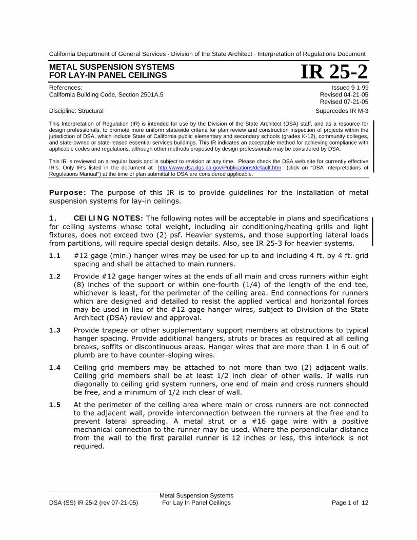
Purpose: The purpose of this IR is to provide a procedure whereby a certificate of compliancemay be issued when it is deemed impossible to collect all the required documents. Thisprocedure may not be initiated until all efforts to obtain the required documents have failed.
1. Procedure. When all efforts to collect the required documents have failed, the school districtmay request in writing to the Division of the State Architect (DSA) that the provisions of Sections17315 and 81147 of the Education Code be implemented. The request should include anexplanation of how the district attempted to obtain the documents, and why the efforts were notsuccessful. DSA reserves the right to insist upon further efforts by the district before initiatingthis procedure if, in the opinion of DSA, such efforts would be productive.
2. DSA Review. The architect or structural engineer will review the project with DSA. Thearchitect or structural engineer will propose a method for satisfying the requirements forcertification. The proposed method may consider, but is not limited to, the following items:
1. Exposure of portions of the construction for inspection of concealed spaces.2. Re-inspection of portions of exposed work.3. Performance testing of materials and/or major components or assemblies.4. Reassignment of delegated responsibilities for field observation or inspection to other
individuals who have personal knowledge of the construction within their area ofresponsibility.
3. Costs. The school district, at its own expense, will proceed with the examinations, tests,and/or inspections deemed necessary. The additional reports and documents will be submittedto DSA. All costs incurred by DSA in implementing this procedure will be billed to the district andwill include time spent by DSA personnel. Payment must be received from the school districtbefore DSA will issue a certificate of compliance for the project.
4. Correction of Deficiencies. Any deficiencies discovered or exposed during re-inspection orre-testing will be corrected at the direction of the school district’s architect and/or structuralengineer. The school district will be responsible for having this work done and completed in atimely manner. The correction work will be subject to the requirements of Title 24.
5. Certification of Compliance. The DSA Field Engineer will review the results of theexaminations, tests and/or inspections. The Field Engineer will assemble all submitteddocuments and determine their acceptability for conformance with statutes and regulationsgoverning public school construction. The Field Engineer will make a recommendation and theentire package will then be reviewed by the Regional Manager. A letter of certification written bythe Regional Manager will indicate the basis for which it is issued.
California Department of General Services . Division of the State Architect . Interpretation of Regulations Document
CERTIFICATE OF COMPLIANCEWITHOUT RECEIPT OF ALL DOCUMENTSReference: California Administrative Code, Section 4-339 Issued 9-1-99Education Code, Section 17315/81147 Supercedes IR 5-1 (3/90)
This interpretation is intended for use by the plan review and field engineers of DSA to indicate an acceptable method for achievingcompliance with applicable codes and regulations. Its purpose is to promote more uniform statewide criteria for use in plan reviewand supervision of construction of public schools, community colleges and essential services buildings. Other methods proposed bydesign professionals to solve a particular problem may be considered by DSA and reviewed for code and regulation compliance.
IR A-2
Purpose: The purpose of this IR is to ensure that the construction management procedurescomply with the requirements of the Education Code and the Division of the State Architect(DSA) regulations.
1. General. The statutes and regulations contemplate the construction of a building by a generalcontractor who would either perform the construction work in its entirety, or employ one or moresubcontractors under his/her responsible supervision to perform specified portions of the work.The general contractor attests to the compliance of the work of construction with the approvedplans and specifications for the project as required by the statute.
It must be understood that the work of the construction manager should not interfere with theprofessional or statutory responsibilities of the design professional for the project, nor restrict theactivities of the project inspector, special inspector, testing laboratory representatives and theField Engineers of DSA in the performance of their duties. It must also be emphasized that theproject inspector is an agent of the owner working under the direction of the architect orstructural engineer in general responsible charge of the project for the purpose of achievingcompliance with the approved plans and specifications, and should not be working under theconstruction manager. Further, the project inspector works under the supervision of DSA for thesame purpose, but also to achieve compliance with the applicable building codes andregulations.
2. Procedures. A project using a construction manager in lieu of a general contractor tocoordinate the work of the subcontractors requires special procedures.
2.1 A construction manager is employed by the owner to assist the owner in the management ofthe construction of the project. The construction manager may perform services in the areas ofcoordination of the work of the various contractors, scheduling the work of the project,monitoring the progress of the work, providing the owner with evaluations and recommendationsconcerning the quality of the work, recommending the approval of progress payments for thecontractors, or other services.
2.2 Without the presence of a general contractor, each subcontractor will enter into an individualcontract with the owner directly to establish conditions for the performance and payment forhis/her work.
2.3 The construction manager will usually be employed to oversee the construction of acomplete building, or group of buildings or the completion of one phase of a long-rangeconstruction program. Each contractor may be employed to start and complete his/her portion ofthe project at any time during the progress of the construction. Therefore, the completion of thatportion of the construction is not synonymous with the completion of the entire project as iscontemplated by the regulations. Each independent contractor who has a contract with theowner is required to submit a final verified report at the completion of his/her portion of the work.
California Department of General Services . Division of the State Architect . Interpretation of Regulations Document
CONSTRUCTION MANAGEMENT PROCEDURESFOR PUBLIC SCHOOL PROJECTSReference: Education Code Sections 17280-17311 and 81130-81147 Issued 9-1-99
Supercedes IR 11-1(9/89)
This interpretation is intended for use by the plan review and field engineers of DSA to indicate an acceptable method for achievingcompliance with applicable codes and regulations. Its purpose is to promote more uniform statewide criteria for use in plan reviewand supervision of construction of public schools, community colleges and essential services buildings. Other methods proposed bydesign professionals to solve a particular problem may be considered by DSA and reviewed for code and regulation compliance.
IR A-3
IR A-3 – Page 2 of 2
2.4 The submittal of verified progress reports by the individual contractors is a departure fromnormal procedures wherein the services of a general contractor are involved. The constructionmanager, who is not a builder by training or licensing, by law, cannot be held responsible for thecompliance of the work of construction with the duly approved plans and specifications for theproject. The Attorney General’s Opinion No. CV 74-160, August 1974, is cited as follows:
"A construction manager does not bind himself to construct a building. See Ops. Cal.Atty. Gen. 9322 (1934). The agreement to do these things is made by the owner withother parties and in case of the failure of any of those parties to perform as agreed, anaction would lie against them and not against the construction manager. The agreementof the construction manager is to perform services only for the owner; that is, tosupervise the work of the contractors who are doing the actual construction."
Therefore, in accordance with DSA regulations, each independent contractor having contractswith the owner, is required to submit verified reports.
3. Contract Information. Contract information on Form SSS-102, to be submitted to DSA, maybe submitted either by the architect/engineer in general responsible charge or by theconstruction manager. If more than one contract is reported at one time, a single Form SSS-102may be used with an attached sheet listing for contractors: the name, address, scope of work,contract price and estimated starting date for each contract.
Each submittal of contract information is to be made on, or attached to, a Form SSS-102. Eachcontract should be identified by a Roman numeral in consecutive order to assist in recordkeeping and future reference (i.e. Contract I, II, III, etc.). Such identification should be noted onchange orders which affect that contract.
California Department of General Services . Division of the State Architect . Interpretation of Regulations Document
(rev 11-01-07) Report Requirements Page 1 of 3
GEOLOGIC HAZARD REPORT REQUIREMENTS Reference: California Building Standards Administrative Code, Section 4-317(e) Revised 11-01-07 2001 California Building Code (CBC) Sections 1629A.4 and 1804A.1 Revised 07-21-05 2007 CBC, Sections 1613A and 1802A Revised 02-03-04 Education Code Section 17212.5. Issued 09-01-99
IR A-4
Discipline: Structural This Interpretation of Regulations (IR) is intended for use by the Division of the State Architect (DSA) staff, and as a resource for design professionals, to promote more uniform statewide criteria for plan review and construction inspection of projects within the jurisdiction of DSA, which include State of California public elementary and secondary schools (grades K-12), community colleges, and state-owned or state-leased essential services buildings. This IR indicates an acceptable method for achieving compliance with applicable codes and regulations, although other methods proposed by design professionals may be considered by DSA. This IR is reviewed on a regular basis and is subject to revision at any time. Please check the DSA web site for currently effective IR’s. Only IR’s listed in the document at http://www.dsa.dgs.ca.gov/Pubs/default.htm (click on “DSA Interpretations of Regulations Manual”) at the time of plan submittal to DSA are considered applicable.
Purpose: The purpose of this Interpretation of Regulations (IR) is to describe the requirements for the submission of a geologic hazard report to the Division of the State Architect (DSA) for projects within the jurisdiction of DSA. 1. GENERAL: A geologic hazard is any geologic condition that is a potential danger to life or property. Geologic hazards include, but are not limited to, earthquake shaking, surface rupture, liquefaction, and landslides. The California Building Standards Administrative Code (CAC), Section 4-317(e) includes requirements for the performance of soils investigation studies and geologic hazard studies for all construction, including additions and alterations. Note that “Geotechnical Reports” (or soils investigation reports) often include soils studies only and may not include complete geologic hazard studies 2. PROJECTS REQUIRING GEOLOGIC HAZARD REPORTS: Except as noted in Section 3, a geologic hazard report shall be submitted to DSA with the project application for projects located in any of the areas described in paragraph 2.1, 2.2, 2.3, or 2.4.
2.1 On any new site.
2.2 Within any “state mandated geologic hazard zone” which includes:
• Earthquake Fault Zones (Public Resources Code (PRC) Div. 2, Ch. 7.5, Sec. 2621 et seq.)
• Seismic Hazard Zones for Landslides and Liquefaction (PRC Div 2, Ch. 7.8, Sec. 2690 et. seq.)
2.3 Within an area identified as a geologic hazard in the Safety Element of the Local General Plan.
2.4 On other existing sites when required by DSA, where a potential geologic hazard has been previously identified.
DSA (SS) IR A-4 Geologic Hazard
DSA (SS) IR A-4 Geologic Hazard (rev 11-01-07) Report Requirements Page 2 of 3 3. PROJECTS NOT REQUIRING GEOLOGIC HAZARD REPORTS: Except as noted in paragraph 2.4, a geologic hazard report will not be necessary for projects on existing sites in any of the situations described in paragraph 3.1, 3.2, or 3.3:
3.1 When the design professional in general responsible charge of the project signs a “Geo-Hazards Statement” on the Application for Approval of Plans and Specifications (Form DSA-1) certifying that the following three conditions are satisfied:
• The project is not located within a state mandated geologic hazard zone, and
• The project is not located within an area identified as a geologic hazard in the safety element of the local general plan, and
• The project is not located within an area where a potential geologic hazard has been previously identified.
3.2 Regardless of location, if the project includes only:
• non-structural alterations which do not cost more than 50% of the replacement cost of the structure, and/or
• incidental structural alterations (alterations which would not reduce the story lateral shear capacity by more than 5% or increase story shear by more than 5% in any existing story), and/or
• one-story wood or light metal frame relocatable buildings on an existing school site that have a floor area of less than 2,160 square feet.
3.3 The project is located on a site for which adequate studies (refer to CGS Note 48 for guidance) have already been made. Documentation of prior studies must be included with the project submittal to DSA.
4. SCOPE OF GEOLOGIC HAZARD STUDIES: For guidance in conducting a study and reporting evaluations and recommendations, refer to:
• Special Publication 117, Guidelines for Evaluating and Mitigating Seismic Hazards in California (1997)
• Special Publication 42 Fault-Rupture Hazard Zones in California (1997 revised edition, including supplements 1 and 2 added in 1999)
both published by the Department of Conservation and available to order from
5. REPORTING PROCEDURES: Two copies of the geologic hazard report must be submitted to DSA along with the initial project application. If a project is submitted without a geologic hazard report DSA may or may not elect to start the plan review process pending receipt of the report.
5.1 DSA will forward geologic hazard reports to the California Geological Survey (CGS) for review for projects within state mandated geologic hazard zones and for other projects as deemed required by DSA.
5.2 CGS will indicate either that a report is acceptable, or describe the reasons why a report is not acceptable, in a letter addressed to DSA and copied to the architect in
DSA (SS) IR A-4 Geologic Hazard (rev 11-01-07) Report Requirements Page 3 of 3
charge of the project. Projects for which a geologic hazard report is required will not be approved by DSA until CGS accepts the geologic hazard report.
6. REPORT REQUIREMENTS: Geologic hazard reports must satisfy the following requirements:
6.1 The report must adequately describe the site to which it applies. The site described must include the locations of all structures to be constructed as part of the project.
6.2 The report must specifically address all of the potential hazards listed in paragraph 1.
6.3 The report must be based on adequate investigation and study of the project site.
6.4 Proper seismic shaking (e.g. upper bound and design basis earthquake ground motion) values must be used in project characterization.
6.5 Adequate documentation must be provided to support conclusions.
6.6 The report must be signed by a California registered geotechnical engineer and a California certified engineering geologist.
6.7 When geologic hazards are identified, the report must provide recommendations for the mitigation of those hazards. If any changes to written recommendations are proposed after evaluation by CGS, then such changes must be submitted immediately to DSA in writing and forwarded to CGS for review.
6.8 CGS Note 48 will be used as a guide for review.
Acceptance of Product DSA (SS) IR A-5 (REV 07-21-05) Evaluation Reports Page 1 of 2
California Department of General Services . Division of the State Architect . Interpretation of Regulations Document
ACCEPTANCE OF PRODUCT EVALUATION REPORTS References: California Building Code, Section 1605A.4 Issued 9-1-99 Discipline: Structural Revised in its entirety 07-21-05 Supersedes IR 14-1 (4/90) This Interpretation of Regulation (IR) is intended for use by the Division of the State Architect (DSA) staff, and as a resource for design professionals, to promote more uniform statewide criteria for plan review and construction inspection of projects within the jurisdiction of DSA, which include State of California public elementary and secondary schools (grades K-12), community colleges, and state-owned or state-leased essential services buildings. This IR indicates an acceptable method for achieving compliance with applicable codes and regulations, although other methods proposed by design professionals may be considered by DSA. This IR is reviewed on a regular basis and is subject to revision at any time. Please check the DSA web site for currently effective IR’s. Only IR’s listed in the document at http://www.dsa.dgs.ca.gov/Publications/default.htm (click on “DSA Interpretations of Regulations Manual”) at the time of plan submittal to DSA are considered applicable.
Purpose: The purpose of this IR is to clarify DSA policy on the acceptability and use of product evaluation reports issued by other agencies and organizations. DSA may accept evaluation reports that meet the eligibility criteria (Section 1) and are used in accordance with Section 2. The intent is to accept evaluation reports for products or materials that comply with the California Building Code (CBC), demonstrate satisfactory performance, and are manufactured under a quality assurance program. Scope: This IR is applicable to evaluation reports for alternate materials per Title 24, Part 1, Section 4-304 and products or materials that are regulated by those provisions in Title 24, Part 2, CBC Chapters 14A through 25A adopted by DSA Structural Safety (DSA - SS).
1. ELIGIBLE REPORTS: For DSA to consider acceptance, evaluation reports issued by other agencies or organizations must meet the following criteria:
1.1 The product or material must comply with the 2001 California Building Code (CBC). Evaluation reports may not be acceptable if the product does not comply with applicable DSA amendments (to the model code) contained in the CBC.
1.2 The evaluation report must be current and valid. Reports that are more than three years old are considered expired except as noted in Section 1.3.1 below.
1.3 The evaluation report must be issued by one of the following DSA recognized agencies or organizations:
1.3.1 International Code Council Evaluation Service. All reports that are currently posted on the ICC ES website are considered current and valid, including reports with prefix ESR and Legacy Reports.
1.3.2 Office of Statewide Health Planning and Development (OSHPD), OPA reports.
1.3.3 City of Los Angeles (COLA), Research Report (RR).
1.3.4 California Department of Transportation (CalTrans).
1.3.5 Miami-Dade County, Florida, Product Control Division, Notice of Acceptance (NOA), for reports relating to wind resistance.
1.3.6 Other product certification bodies that are certified to be in compliance with ISO Guide 65, "General Requirements for Bodies Operating Product Certification Programs".
IR A-5
Acceptance of Product DSA (SS) IR A-5 (rev 07-21-05) Evaluation Reports Page 2 of 2 1.4 The evaluation report must be issued on the following basis: 1.4.1 Compliance with CBC adopted model code and referenced standards, established
acceptance criteria, and/or industrial standards, e.g. ASTM specification. 1.4.2 Review of test results and the tests are conducted in compliance with established
test procedures. 1.4.3 Review of Quality Assurance and Control program that shall include periodic
independent third party audits. 1.5 Products or materials listed in evaluation reports must have continued acceptable
performance.
2. USE OF REPORTS: Eligible evaluation reports, per Section 1 of this IR, may be accepted for use on projects under DSA jurisdiction, if used in accordance with the following:
2.1 The design, application and installation of the product shall comply with the require-ments of CBC, and the applicable evaluation reports.
2.2 For products or materials used to resist lateral forces, use 80% of the listed values in the evaluation reports unless the listed values were established on the basis of cyclic test results.
2.3 The design calculations, plans, specifications, and applicable evaluation reports shall be incorporated into the project documents and submitted to DSA with the project application package.
2.4 For certain types of products, the evaluation report may not be the sole basis for acceptance. DSA regional offices will review, on a project specific basis, those products or materials that require the following:
• Substantial project or site-specific design or engineering
• Custom assembly or construction on site
The following are examples of these types of products:
• Earth retaining systems such as segmental walls
• Foundation systems such as rammed aggregate piers
• Proprietary steel Special Moment Resisting Frame (SMRF) connections
2.5 DSA PRODUCT ACCEPTANCE REPORTS: Some types of products have been
proposed frequently for projects under DSA jurisdiction. The manufacturers of the below listed product types with a recognized listing may apply for a DSA Product Acceptance (PA) report.
• suspended acoustic ceiling grid system • engineered wood products (e.g. I-Joists, LVL, etc.) • manufactured shear wall systems
Change Order and Field Change DSA IR A-6 (rev 09-18-07) Approval Process Page 1 of 8
California Department of General Services . Division of the State Architect . Interpretation of Regulations Document
CHANGE ORDER AND FIELD CHANGE APPROVAL PROCESSES References: California Administrative Code, Sections 4-305 and 4-338 Revised 09-18-07 Discipline: All Revised in its entirety 11-15-06 Issued 9-1-99 This Interpretation of Regulation (IR) is intended for use by the Division of the State Architect (DSA) staff, and as a resource for design professionals, to promote more uniform statewide criteria for plan review and construction inspection of projects within the jurisdiction of DSA, which include State of California public elementary and secondary schools (grades K-12), community colleges, and state-owned or state-leased essential services buildings. This IR indicates an acceptable method for achieving compliance with applicable codes and regulations, although other methods proposed by design professionals may be considered by DSA. This IR is reviewed on a regular basis and is subject to revision at any time. Please check the DSA web site for currently effective IR’s. Only IR’s listed in the document at http://www.dsa.dgs.ca.gov/Pubs/default.htm (click on “DSA Interpretations of Regulations Manual”) at the time of plan submittal to DSA are considered applicable.
Purpose: The Code requires that all changes to the approved plans or specifications after a contract for the construction has been awarded shall be made only by means of change orders approved by the Division of the State Architect (DSA). This interpretation describes a process for obtaining approval of changes by DSA.
Discussion: Section 4-338 (c) and (d), Part 1, Title 24, California Code of Regulations (CCR), describes DSA’s process for approval of “change orders” and “preliminary change orders.” DSA has determined that to provide timely, efficient and consistent approval of changes during construction, enforcing the strict letter of regulations may require flexibility. An alternate “field change document” approval process is described in this IR. This process focuses the designer’s and DSA’s efforts on code compliance with the goal of timely review and approval.
Definitions. The following definitions apply to terms used in this document:
Approved Documents – Plans, specifications, addenda, deferred approvals, field change documents, and change orders bearing a valid DSA approval stamp. A valid DSA approval stamp includes the DSA application number for the project, the initials of the plan reviewer(s) and the date of approval. Stamps without the initials of the plan reviewer(s) and the date are NOT indicative of approval.
Change - Changes to the approved plans or specifications include revisions, deletions, additions, and substitutions to the work prescribed on the approved plans or specifications.
Change Order – A document defining changes to the DSA approved plans and/or specifications issued after a construction contract has been awarded. Change orders may also define changes to contractual requirements, including costs and time requirements that are not regulated by the California Building Code.
Clarification - a statement from the architect or engineer in general responsible charge of the project that clarifies (but does not change) the requirements of the DSA approved plans and/or specifications.
Contract – A document that defines the cost or value of some or all of the construction work. When labor and/or materials are donated, or provided by the school district/owner, the value of the materials and/or work must be estimated and reported to DSA on Form DSA-102 as if there was an actual "contract" for that work. Also, contracts for construction management must be reported on Form DSA-102.
Design Professional – An individual listed on application Form DSA-1 Lines 4, 5, 6 or 7.
Field Change Document (FCD) – A document defining changes to the Code regulated construction requirements of the DSA approved plans and/or specifications issued after a
IR A-6
Change Order and Field Change DSA IR A-6 (rev 09-18-07) Approval Process Page 2 of 8 construction contract has been awarded. FCDs may include Architect’s Supplemental Instructions (ASI), Instruction Bulletins (IB), Field Orders (FO), Construction Change Directives (CCD), etc.
Drawing – an illustration on paper larger than 8 1/2 x 14.
Interpretation – a statement from the architect or engineer in general responsible charge of the project that interprets (but does not change) the requirements of the DSA approved plans and/or specifications.
Sketch – an illustration on 8 1/2 x 11 or 8 1/2 x 14 paper.
1. Scope. After a contract for construction has been awarded, DSA approval of changes to approved documents shall be obtained in accordance with the following:
1.1 Changes That Require DSA Approval Prior to Construction. DSA approval shall be obtained for changes to all Code-regulated construction and inspection/testing functions prior to commencement of the affected work. Changes can be approved through the field change document (FCD) approval process described in Section 3.1 below or the change order process described in Section 3.2. DSA-approved FCD, or change order, documents shall be in the possession of the contractor and the inspector prior to construction of the work shown thereon.
“Code-regulated” refers to work that is regulated by the provisions of Title 24 of the California Code of Regulations applicable to the construction, including those amendments to the Code adopted by DSA-SS (Structural Safety), DSA-AC (Access Compliance), and the SFM (State Fire Marshal). For projects submitted under the 2001 CBC, refer to 2001 CBC, Part 2, Sections 101.17.11 (DSA/AC), 101.17.12 (DSA/SS), and 101.17.14 (SFM). [For projects submitted under the 2007 CBC, refer to 2007 CBC, Part 2 Section 101.3.2 items 4, 10 (DSA/AC), 11 (DSA/SS) and 14 (SFM)].
Note that although DSA does not currently conduct a specific review of certain aspects of construction (including mechanical, electrical, etc) these aspects are considered to be “Code regulated” and must be submitted as part of an FCD or change order.
DSA approval is also required for all change orders.
1.2 Changes That Do Not Require DSA Approval. DSA approval is not required for FCDs if the scope of the change does not pertain to Code-regulated construction (refer to Section 1.1 above). For example:
• Color of finishes, and
• Administrative changes to the contract (e.g. contract time extension).
1.3 Interpretations and Clarifications. Responses to request for information, interpretations, clarifications, and other communications that do not change the requirements of the DSA stamped approved documents may be issued by the architect or engineer in general responsible charge. These documents do not require DSA approval. 2. General Requirements. All change orders and field change documents must conform to the following general requirements (see sample change order, which includes a sample FCD, in the appendix):
2.1 The project name and the name of the facility must be indicated.
2.2 The DSA file and application numbers must be shown in the upper right hand corner.
Change Order and Field Change DSA IR A-6 (rev 09-18-07) Approval Process Page 3 of 8 2.3 All FCDs and change orders shall be numbered in sequence in a logical and
consistent manner. The number must be shown in the upper left corner.
2.4 All changes must be described clearly and completely by the architect in general responsible charge of the project and/or architects or engineers with delegated responsibility for portions of the project as defined on Form DSA-1 – Application for Approval of Plans and Specifications.
2.5 Reference to the specific portions of the drawings and/or specifications that are being changed must be included. All details and specification sections affected by the change shall be coordinated. If a change to a detail is only applicable in some of the locations for which the detail applies, those locations must be clearly described.
2.6 Changes to any testing or inspection requirements associated with the proposed change must be clearly described.
2.7 The number of pages in the FCD or change order, including the number of pages in each attachment, shall be clearly indicated. All sketches and drawings attached to describe the changes shall be clearly labeled and referenced.
2.8 When approved drawings are revised and reissued as part of an FCD or change order all of the following requirements must be met:
2.8.1 Images of all DSA approval stamps must be removed from the drawing (or crossed out) prior to making any changes.
2.8.2 Each change shall be highlighted on the drawing and identified (see example change order attached in appendix).
2.8.3 Each change shall be dated.
2.8.4 All drawings shall be stamped and signed by the design professional in general responsible charge. When preparation of a drawing has been delegated to another design professional that individual shall also stamp and sign the drawing.
2.9 FCDs and change orders should include only clear instructions on specific changes to details on the DSA approved drawings or sections of the DSA approved specifications. When circumstances make it necessary to submit additional back up information the following requirements shall be met:
2.9.1 Calculations, product “cut-sheets” and other back-up information necessary to demonstrate that the changes are Code compliant shall be submitted along with (but not as part of) the FCD or change order. Calculations or other information that is not necessary to define the work required shall not be placed on sketches or drawings included in an FCD or change order.
2.9.2 Cost estimates, cost justifications, or other back-up documents that are not necessary to define the changes to the DSA approved drawings or specifications need not be submitted to DSA. If back-up information is submitted for any reason, it must be separate from the FCD or change order.
2.9.3 For work involving alterations to existing buildings it is sometimes expedient to submit drawings of the existing building as back-up information to clarify or justify the acceptability of proposed changes. DSA will return existing building drawings when the architect or engineer clearly requests the return of such drawings in advance.
2.10 A reason shall be provided for each change.
2.11 The appropriate design professional (listed on application Form DSA-1) must sign the FCD or change order (change orders must also be “stamped”).
Change Order and Field Change DSA IR A-6 (rev 09-18-07) Approval Process Page 4 of 8 2.12 All engineers or architects for whom responsibility for portions of the work has been
delegated must sign the FCD or change order when their portion of the work may be affected by the changes (change orders must also be “stamped”).
2.13 Space (2 in. x 3 in.) for a DSA approval stamp must be provided.
3. Approval Process. The design professional shall obtain DSA approval for changes to the approved plans or specifications in accordance with Section 3.1 or 3.2. DSA shall direct all communications (review comments and/or approved documents) to the responsible design professional.
3.1 Field Change Document Approval (FCD) Process. This process can provide responsive processing of documentation for changes that require DSA approval prior to construction of the work shown thereon (refer to 1.1). FCDs do not require documentation of school board approval.
Change documents can be transmitted via fax or other expedient means for review by DSA (recommend faxable format of 8-1/2 x 11, with design professional's phone/fax number noted). DSA can communicate review comments and approved FCDs to the responsible design professional via fax or mail.
Information required to be provided with an FCD submittal is listed in Section 2 above.
3.2 Change Order (CO) Approval Process. DSA approved FCDs are not required to be included in a formal change order. DSA stamped approved FCDs may be included in formal change orders and are not subject to further technical review. If an approved FCD is incorporated into a change order, the complete FCD bearing the approval stamp of DSA shall be attached and referenced in the change order. All documents included which do not bear a DSA approval stamp will be reviewed for Code compliance.
The design professional shall submit two copies of each change order to DSA for review and approval; one copy of the approved change order shall be retained by DSA and one returned to the design professional. Back-up information and extra copies of change orders will NOT be returned (exception: see 2.9.3 above).
General information required to be provided with the change order submittal is listed in Section 2 above; additional information required for change orders includes:
• Stamp (in addition to signature) of the architect or engineer in general responsible charge and of each consultant delegated responsibility for work affected by the change order.
• Contract number when more than one contract is awarded for the project,
• Cost information, and
• Signature of the School District (owner).
4. Design Professionals' Duties. The design professionals have specific Code-prescribed duties with regard to changes to the approved plans and/or specifications. (See Sections 3-341, Part 1, Title 24, CCR.)
4.1 Documentation/Processing. The design professional shall prepare FCDs and change orders as required by conditions on the project and shall make corrections as required to comply with the regulations.
Change Order and Field Change DSA IR A-6 (rev 09-18-07) Approval Process Page 5 of 8 4.2 Signing/Stamping. The design professional shall stamp and sign all documents
(note that all “drawings” must be stamped and signed; all “sketches” must be signed).
4.3 Communications. The design professional shall provide the contractor, testing laboratory, and the inspector with DSA stamped approved documents prior to commencement of Code-regulated work shown thereon.
4.4 Final Verified Report. The design professionals’ final verified report (Form DSA-6A/E) shall indicate the total number of change orders issued.
4.5 Cost Summary. The design professional shall report the total final construction cost of the project on Form DSA-6A/E. The construction cost shall include the final amount of all construction contracts, construction management agreements, and estimated value of all construction work performed by volunteers or school district employees.
5. Inspector's Duties. The project inspector has specific Code-prescribed duties with regard to changes to the approved plans and/or specifications issued in the field. (See Section 4-342. Part 1, Title 24, CCR.)
5.1 Record-keeping. The inspector shall maintain a file of approved FCDs and change orders on the job at all times. The inspector is required to maintain complete records of these documents. These documents shall be maintained in an organized manner so that they are readily available.
5.2 Communications. If the inspector determines that unapproved documents appear to require DSA approval (the document directs a change to Code-regulated construction), the inspector shall notify the design professional and DSA immediately. Any work performed that is not in accordance with DSA approved documents must be reported as a deviation.
5.3 Final Verified Report. The inspector's Final Verified Report (form DSA-6) shall indicate the total number of change orders received and implemented.
APPENDIX
• Sample Change Order
• Sample Field Change Document (FCD)
Change Order and Field Change Approval Process DSA IR A-6 (rev 09-18-07) APPENDIX – SAMPLE CHANGE ORDER Page 6 of 8
Change Order #: 2 DSA File #: 99-123 Contract #: 1 Application #: 02-123456 Project: Really Smart Architects Perfectly Designed Elementary School 432 Professional Drive 123 School Drive Emerald City, CA 90210 Smallville, CA 91020 Phone #: 916-445-8100 Fax #: 916-445-8100 To: Excellent Contractors 654 Concrete Road City of Industry, CA 92010 The contract is changed as follows:
1. Revise specification section 12512 to eliminate all reference to horizontal louver blinds.
Requested by: Owner Reason: Window coverings will be provided in another contract Credit $ <960.00>
2. Refer to detail 17 on sheet A57. Add treated wood buck, 7/8" thick x width of CMU wall, at each jamb of door 710. Secure to masonry with 1/4" diameter expansion anchors with 1-1/4"embedment at 24" on center. Requested by: Architect Reason: To allow for proper installation of door. Add $ 760.00
3. Refer to attached FCD #1 (1 page). Change maximum non-shrink grout thickness from ½" to 1".
Requested by: Contractor Reason: Elevator was installed on 1" of grout; owner will accept this deviation for a credit. Credit $ <100.00>
4. Increase contract time by seven working days.
Requested by: Contractor Reason: Rain delays
Change Order and Field Change Approval Process DSA IR A-6 (rev 09-18-07) APPENDIX – SAMPLE CHANGE ORDER Page 7 of 8 Total Cost of This Change Order: Credit $ <300.00> The original Contract Sum was …………………………………………….. $900,000.00 Net change by previously authorized change orders ……………………. $ 0.00 The contract sum prior to this change order was ………………………… $900,000.00 The contract sum will be (decreased) by this change order by ………… $ <300.00> The new contract sum including this change order will be ……………… $899,700.00 The contract time will be (increased) by ………………………………….. (7) working days The date of substantial completion as of the date of this change order is May 1, 2006 Architect: Date: Frank L. Wright, Architect
Really Smart Architects ((aaffffiixx ssttaammpp hheerree)) Structural Engineer: Date: Joe Excellent, President
Excellent Engineering, Inc. ((aaffffiixx ssttaammpp hheerree))
Owner: Date: Hal T. Computer, Director of Facilities Smallville Unified School District ((ssppaaccee ffoorr DDSSAA aapppprroovvaall ssttaammpp))
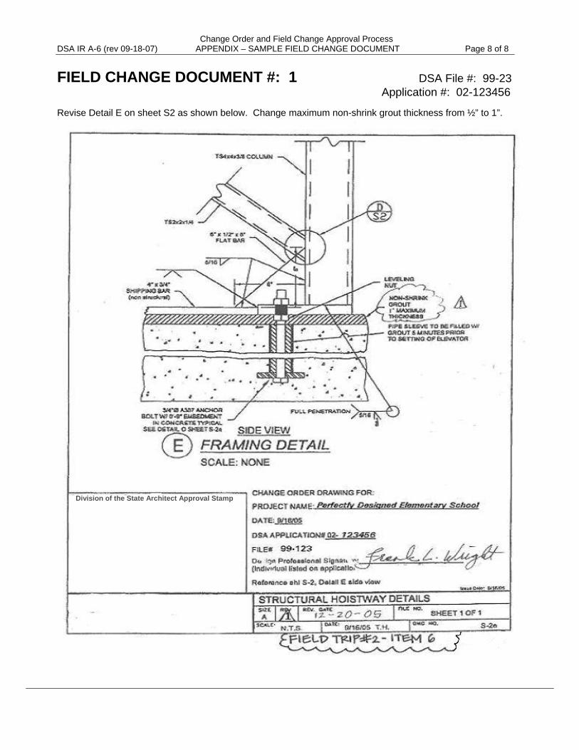
Change Order and Field Change Approval Process DSA IR A-6 (rev 09-18-07) APPENDIX – SAMPLE FIELD CHANGE DOCUMENT Page 8 of 8
FIELD CHANGE DOCUMENT #: 1 DSA File #: 99-23 Application #: 02-123456 Revise Detail E on sheet S2 as shown below. Change maximum non-shrink grout thickness from ½” to 1”.
Division of the State Architect Approval Stamp
Project Inspector DSA IR A-7 (rev 09-18-07) Certification and Approval Page 1 of 6
California Department of General Services . Division of the State Architect . Interpretation of Regulations Document
PROJECT INSPECTOR CERTIFICATION AND APPROVAL Reference: California Building Standards Administrative Code (Title 24, Part 1) Revised 09-18-07
Sections 4-211, 4-333, & 4-341 Revised 06-01-06 California Education Code, Sections 17309, 17311 & 81141 Revised 09-10-02 Issued 9-1-99 This Interpretation of Regulation (IR) is intended for use by the Division of the State Architect (DSA) staff, and as a resource for design professionals, to promote more uniform statewide criteria for plan review and construction inspection of projects within the jurisdiction of DSA, which include State of California public elementary and secondary schools (grades K-12), community colleges, and state-owned or state-leased essential services buildings. This IR indicates an acceptable method for achieving compliance with applicable codes and regulations, although other methods proposed by design professionals may be considered by DSA. This IR is reviewed on a regular basis and is subject to revision at any time. Please check the DSA web site for currently effective IR’s. Only IR’s listed in the document at http://www.dsa.dgs.ca.gov/Pubs/default.htm (click on “DSA Interpretations of Regulations Manual”) at the time of plan submittal to DSA are considered applicable.
Purpose: This IR describes the requirements for the certification and approval of school construction project inspectors. All project inspectors must complete this two-step process of certification and approval by DSA before they are permitted to work on school construction projects.
Section 1 of this IR explains the requirements for DSA Certification of project inspectors. Section 2 specifies the requirements for DSA Approval of the project inspector. Duties of Inspectors are described in DSA IR A-8. The acceptance and approval of assistant inspectors is described in DSA IR A-12.
Certification & Approval – a Two-Step Process
Certification is the first step in becoming a school construction project inspector. This step occurs only once. An inspector may become DSA-Certified by successfully completing the DSA Project Inspector Examination. There are four classes of certification. These classes correspond to a project class assigned to each project by DSA. See Section 1 below. Certification is only one of several factors involved in the approval process.
Approval is the second step. This step occurs on every project. Approval of the project inspector by the DSA Regional Office must be obtained before the inspector is permitted to work on a project. DSA Approval is based on several factors, one of which is DSA Certification in the proper class. See Section 2 below.
Section 1 – CERTIFICATION of the INSPECTOR
As required by law, all project inspectors must be certified through the DSA Project Inspector Examination Program.
Examinations are given in each of four project classes. The examinations measure the applicant’s ability to read and comprehend construction plans and the California Building Standards Code.
The DSA Project Inspector Examination Program does not qualify an applicant as a “special” inspector.
The Class 1 Project and the Class 1 Examination
Projects that are designated as Class 1 must contain one or more “Class 1 structures” (as defined below) but may also contain Class 2, Class 3, or Class 4 structures. The Class 1
IR A-7
Project Inspector DSA IR A-7 (rev 09-18-07) Certification and Approval Page 2 of 6 examination is comprehensive; it tests the applicant’s knowledge of Class 1, Class 2, Class 3, and Class 4 structures and related code requirements.
Class 1 structures include:
Buildings or additions of 2,000 square feet or greater that utilize materials other than wood-frame shear walls (masonry/concrete shear walls, steel brace frames, concrete, or steel moment-resisting frames) as the primary lateral-load resistive system.
Substantial structural alterations to the gravity and/or lateral load-resisting system of the building types described above.
The Class 2 Project and the Class 2 Examination Projects that are designated as Class 2 must contain one or more “Class 2 structures” (as defined below) but may also contain Class 3 or Class 4 structures. The Class 2 examination tests the applicant’s knowledge of Class 2, Class 3, and Class 4 structures and related code requirements.
Class 2 structures include:
Buildings or additions over 2,000 square feet in floor area that utilize wood-frame shear walls as the primary lateral load-resistive system. Projects may be single or multi-level, with no upper limit in floor area. The project may contain incidental masonry, concrete and/or structural steel construction (e.g. gravity load carrying columns and beams). Buildings may have isolated exceptions to the lateral load resistive system, such as a steel brace frame at one location in the structure.
Buildings or additions of less than 2,000 square feet in floor area that have primary lateral load-resistive systems utilizing concrete, masonry or steel construction. A single-story masonry building with a regular configuration a floor area of less than 7,000 square feet, and a wood-frame roof structure may be considered to be a Class 2 structure. For a definition of “regular configuration see 2001 CBC, Section 1629A.5.2 for projects regulated by the 2001 CBC (or see ASCE 7, Section 12.3.2 for projects regulated by the 2007 CBC).
On-site construction of two-story modular buildings.
Alteration, modernization, and reconstruction projects that exceed the limitations of the Class 3 scope of work, and do not include substantial alterations to structural systems of concrete, steel or masonry.
Non-building structures that exceed the limitations of the Class 3 scope of work.
The Class 3 Project and the Class 3 Examination
Projects that are designated as Class 3 must contain one or more “Class 3 structures” (small buildings of wood-frame construction and/or modernization/alteration projects) but may also contain Class 4 structures. The Class 3 examination tests the applicant’s knowledge of both Class 3 and Class 4 structures and related code requirements.
Class 3 structures include:
Buildings or additions of wood frame, single-story construction, with conventional (spread footing) concrete foundations and a total floor area less than 2,000 square feet. Structures must utilize wood-frame shear walls as the primary lateral load-resistive system. The project may include isolated steel or concrete elements (e.g. steel or concrete columns).
Project Inspector DSA IR A-7 (rev 09-18-07) Certification and Approval Page 3 of 6 Structural alteration projects limited to wood-frame, single story construction. When
deemed appropriate by DSA, alterations to (or addition of) isolated steel, masonry or concrete elements may be included in Class 3 projects. Alteration projects involving significant changes to the lateral load-resisting system may be classified as Class 2 projects.
Alteration and modernization projects that are primarily non-structural, such as electrical, mechanical, plumbing, disabled access features, and site improvement work.
Non-building structures, such as signs and poles less than 35' in height, bleachers with a maximum of 5 rows of seats, walls less than 10' in height above grade, and single-story canopies less than 200 square feet in horizontal projected area.
The Class 4 Project and the Class 4 Examination
Projects that are designated as Class 4 only include “Class 4 structures” (building placement and related site work for premanufactured single-story relocatable buildings). The Class 4 examination tests the applicant’s knowledge of Class 4 structures and related code requirements. Class 4 structures include only site installation of premanufactured, single-story relocatable buildings.
Relocatable Building Inspector - In Plant (“RBIP” Inspectors)
Inspectors of factory-built relocatable buildings must be certified through either the DSA RBIP examination or the Class 1 project inspector examination. The RBIP examination is scheduled through the DSA Headquarters Office (contact DSA Headquarters at 916/554-7019).
Expiration and Recertification
An inspector’s certification expires four years from the date of issue. To renew the certification, each inspector must complete the requirements of the DSA Inspector Re-Certification Program every four years. The re-certification program consists of the DSA Academy Project Inspector Overview Class and a re-certification class conducted by DSA. Further information regarding the requirements of re-certification may be obtained on-line at www.dsa.dgs.ca.gov (click on “Inspector Program”). For information on the Project Inspector Overview Class, refer to http://www.dsaacademy.dgs.ca.gov/.
For Specific Examination Information The DSA Project Inspector Examination Program is administered by the DSA Headquarters office. For information regarding the examination schedule, locations, examination fees, or to obtain an application, contact DSA Headquarters, by phone at 916/554-7019, or on-line at www.dsa.dgs.ca.gov (click on “Inspector Program”).
Section 2 - APPROVAL of the PROJECT INSPECTOR
As required by law, all project inspectors must be DSA approved for work on each individual project.
To apply for approval, the design professional in general responsible charge must submit an Inspector’s Qualification Record form (Form DSA-5) to the appropriate DSA Regional Office at least ten days prior to the start of construction. The inspector must complete the form. The form must be signed by the inspector, the school district representative, the design professional in general responsible charge, and the structural engineer delegated responsibility for observation of construction.
For Approval on Class 1 and Class 2 projects: Before submitting a Form DSA-5 for Class 1 or Class 2 projects, the design professional in general responsible charge must consult the DSA
Project Inspector DSA IR A-7 (rev 09-18-07) Certification and Approval Page 4 of 6 field engineer assigned to the project by the DSA Regional Office. The design professional and the DSA field engineer must review the inspector’s qualifications for the project with regard to DSA approval criteria (see DSA Approval of the Project Inspector on page 6 of this IR). The use of assistant inspectors must also be considered at this time (see DSA IR A-12).
Review of the Inspector’s Qualifications by the School District and Responsible Design Professionals
The following five items must be reviewed by the design professional in general responsible charge, the structural engineer delegated responsibility for observation of construction, and the school district prior to submitting the Form DSA-5 to the DSA Regional Office for Inspector Approval:
1. The Class of the Inspector’s Certification and the Project Class
The project inspector's DSA certificate number and class designation must be provided on the Form DSA-5. The project classification must also be provided on the Form DSA-5. The project’s classification is determined by DSA during plan review, and is indicated on the Approval of Plans notification (issued after approval of plans and specifications). The project classification can also be checked on line at the DSA Tracker web site at http://www.applications.dgs.ca.gov/dsa/eTrackerWeb/Input_App.asp
Project inspectors with Class 1 certification may apply for DSA Approval to inspect any project. Project inspectors with Class 2 certification may apply for approval to inspect projects that are designated as Class 2, 3, or 4. Project inspectors with Class 3 certification may apply for approval to inspect projects that are designated as Class 3 or 4. Project inspectors with Class 4 certification may only apply for approval on Class 4 projects.
2. Inspector’s Work Experience
DSA approval is contingent upon the inspector’s experience in inspection or construction work on building project(s) of a type similar to that of the individual project for which the inspector is applying. The inspector must describe qualifying experience from three building construction projects on the Form DSA-5. Qualifying experience is defined by the types of duties performed and the types of projects on which those duties were performed.
Types of Duties: Prior job positions and responsibilities are the primary considerations of qualifying experience. The inspector’s prior responsibilities for either inspection or construction should include experience with the trades that will be utilized on the project for which the inspector is applying. Job positions that may provide qualifying experience include:
Project Inspector (providing continuous inspection of an entire project). Prior experience as a project inspector is required for Class 1 and large Class 2 projects.
DSA-approved Assistant Inspector.
General Contractor’s Field Superintendent.
Special Inspector or Construction Trade Foreman. These positions provide qualifying experience only in the specific trade(s) in which the individual worked.
Other job positions are unlikely to provide sufficient experience for approval by DSA as a project inspector.
Types of Projects: The types of projects that provide qualifying experience must be relevant to the type of project for which the inspector is applying. Project aspects (both
Project Inspector DSA IR A-7 (rev 09-18-07) Certification and Approval Page 5 of 6
for prior projects and the project for which the inspector is applying) that must be considered include:
Materials of the Structural System (wood-frame, concrete, masonry, steel).
Complexity of the Structural System (configuration of buildings, number of floors, unusual design features).
Size (square footage of new construction, total construction cost).
3. On-Site Presence of the Project Inspector
Two important aspects must be considered:
a. The inspector must be present on the job-site when there is construction activity. The inspector’s schedule must allocate sufficient time to perform all required duties on the project for which the inspector is applying. The inspector must indicate on the Form DSA-5 whether presence on the job-site will be full-time (40 hours per week or more) or part-time (less than 40 hours per week). Large projects usually require a full-time commitment from the inspector.
b. If the inspector has other work commitments concurrent with the project for which the inspector is applying, each school project, each non-school project, and/or other employment commitments must be described on the Form DSA-5. For each concurrent project the following information must be provided:
Project name and location
DSA Application Number (if school project)
Scope of the project (new construction, building size, number of buildings, construction cost)
Current status of project (% complete)
The responsible design professionals, the school district, and DSA must conclude that the inspector’s schedule will allow for an adequate presence on the job-site. In the event that the school district, the responsible design professional(s), or DSA conclude that the inspector’s schedule as described on the Form DSA-5 will not allow for sufficient presence on the job-site, the inspector will be afforded an opportunity to provide additional information for re-evaluation.
The inspector must obtain prior written approval from the school district, the responsible design professional(s), and DSA for any changes to the time commitment or workload from that indicated on the approved Form DSA-5.
4. School District and Design Professional’s Interview of the Inspector
DSA recommends that the school district and the responsible design professional(s) conduct a personal interview with the inspector before signing the Form DSA-5. The following points should be considered:
The inspector’s knowledge of his/her role and responsibilities, job duties, and limits of authority.
Characteristics of the inspector necessary to develop and maintain satisfactory working relationships. Such characteristics include effective communication skills, patience, determination, consistency and the ability to exercise sound judgment.
Inspector’s physical ability and stamina to inspect all construction and to maintain a responsive presence on the job.
Project Inspector DSA IR A-7 (rev 09-18-07) Certification and Approval Page 6 of 6
Inspector’s knowledge of construction methods, building materials, material testing/special inspection procedures and building codes applicable to the project. The inspector must be able to read and readily comprehend the requirements of the project plans and specifications.
5. DSA Approval of the Project Inspector
The project inspector must be DSA approved for each individual project. The DSA field engineer’s approval of the proposed inspector is based on the following criteria:
The proper relationship between the class of the inspector’s certification and the project’s classification, as described in item number 1 on page 4.
The inspector’s work experience, as described in item number 2 on page 4.
The inspector’s workload and time commitment to the project, as described in item number 3 on page 5.
The utilization of assistant inspector(s) as described in DSA IR A-12.
Satisfactory DSA performance ratings on previous school construction projects (refer to DSA IR A-8).
Verification that the inspector is employed by the school district.
If the inspector meets the requirements for approval, the DSA field engineer will sign the Form DSA-5, which indicates DSA approval. A copy of the signed Form DSA-5 will be promptly returned to the inspector and the design professional in general responsible charge. If DSA is unable to grant approval, the Form DSA-5 will be promptly returned to the design professional in general responsible charge, with documentation of the reason(s) why approval was not granted. The proposed inspector may be reconsidered for approval if these documented reasons are satisfactorily addressed on the resubmitted Form DSA-5.
6. Withdrawal of Approval and/or Certification
The DSA field engineer observes the project inspector’s performance of code-prescribed duties during the course of construction. IR A-8 describes the required duties and responsibilities of the project inspector. Failure to perform duties as required may result in the withdrawal of approval and/or certification of the project inspector.
The DSA field engineer completes an Inspector’s Performance Rating for the project inspector (Form DSA-180-5.1) and for the assistant inspector (Form DSA-180-5.1a) at the final site visit (refer to IR A-8, Section 2). The performance rating is used by DSA as a basis for approval of the project inspector and the assistant inspector on future projects.
DSA IR A-8 Project Inspector & Assistant Inspector (rev 09-27-07) Duties and Performance Page 1 of 6
California Department of General Services . Division of the State Architect . Interpretation of Regulations Document
PROJECT INSPECTOR & ASSISTANT INSPECTOR DUTIES AND PERFORMANCE Reference: California Building Standards Administrative Code (Title 24, Part 1) Revised 09-27-07 Sections 4-211, 4-333, 4-334, 4-336, 4-337, 4-342, & 4-343 Revised 05-16-07 California Education Code, Sections 17309 & 81141 Revised 06-01-06 Revised 01-25-02 Issued 09-01-99
This Interpretation of Regulation (IR) is intended for use by the Division of the State Architect (DSA) staff, and as a resource for design professionals, to promote more uniform statewide criteria for plan review and construction inspection of projects within the purview of DSA. This IR indicates an acceptable method for achieving compliance with applicable codes and regulations, although other methods proposed by design professionals may be considered by DSA. This IR is reviewed on a regular basis and is subject to revision at any time. Please check the DSA web site for currently effective IR’s. Only IR’s listed in the document at http://www.dsa.dgs.ca.gov/Pubs/default.htm (click on “DSA Interpretations of Regulations Manual”) at the time of plan submittal to DSA are considered applicable.
Purpose: This IR provides clarification of the duties of school construction project inspectors and assistant inspectors as required by the California Building Standards Code (Title 24, Part 1). The IR also describes the performance rating process utilized by DSA to evaluate inspectors for approval on future school construction projects.
Section 1 - REQUIRED DUTIES of the PROJECT INSPECTOR
The project inspector must perform specific duties in accordance with Title 24, Part 1 (Sections 4-333, and 4-342). The project inspector acts under the direction of the design professional in general responsible charge and is subject to supervision by DSA. The project inspector does not have the authority under Title 24 to direct the contractor in the execution of the work, nor to stop the work of construction.
The project inspector’s responsibilities include:
• A thorough understanding of all requirements of the construction documents.
• Inspection of all portions of the construction for compliance with the requirements of the DSA approved construction documents.
• Identification, documentation, and reporting of deviations in the construction from the requirements of the DSA approved construction documents.
• Submittal of verified reports (Form DSA-6). At the conclusion of the project any outstanding deviations must be noted on the Form DSA-6.
Seven Categories of Code-Prescribed Duties of the Project Inspector
The code-prescribed duties of the project inspector have been organized into the following seven categories. The inspector’s performance in each of these categories serves as the basis for the DSA field engineer’s rating of the inspector (see Section 2 on page 5 of this IR).
1. Inspector’s Job File
The inspector must maintain approved (DSA-stamped and initialed) construction documents at the job-site in an organized, readily accessible manner. The inspector must also maintain any other construction documents or directives received from the responsible design professional(s).
IR A-8
DSA IR A-8 Project Inspector & Assistant Inspector (rev 09-27-07) Duties and Performance Page 2 of 6 The following list of documents and codes must be maintained at the job-site, and available for review by DSA representatives, during construction:
• Building Codes: Title 24, Part 1 (Administrative Code); Title 24, Part 2, Volumes 1, 2, and 3 (Building Code); Title 24, Part 3 (Electrical Code); Title 24, Part 4 (Mechanical Code); Title 24, Part 5 (Plumbing Code) and Title 24, Part 6 (Energy Code). The code edition must be as referenced on the DSA approved plans and specifications.
• DSA approved plans and specifications.
• DSA approved addenda.
• DSA approved deferred approval documents.
• DSA approved Field Change Documents.
• DSA approved change orders.
• A copy of shop drawings, samples, and approved submittals.
• Test and Inspection List (Form DSA-103).
• Test and special inspection reports.
• Deviation reports and logs.
• Daily inspection reports.
• Semi-monthly reports.
• Any other documents or directives received from the responsible design professional(s).
2. Inspector’s Comprehension of the Construction Documents
The inspector must study and fully comprehend the requirements of the construction documents in order to provide competent inspection of the work. It is necessary for the inspector to possess a thorough understanding of the requirements of the plans and specifications before that portion of the work is performed.
The inspector must:
• Consult the responsible design professional(s) to resolve any uncertainties in the inspector’s comprehension of the plans and specifications prior to construction of that portion of the work.
• Review requirements for each phase of the construction with the contractor prior to commencing that phase of the work. Good communications will prevent construction errors from occurring.
• Readily identify non-compliant work as the construction progresses, to facilitate prompt corrective action.
• Verify code-compliant implementation of the materials testing and special inspection program.
Title 24, Part 1, Section 4-343, specifies that the contractor must direct inquiries regarding document interpretation (including Requests for Information or RFI’s) to the design professional in general responsible charge, through the inspector. This code provision requires the contractor to involve the inspector in the interpretation and clarification of the construction documents.
DSA IR A-8 Project Inspector & Assistant Inspector (rev 09-27-07) Duties and Performance Page 3 of 6 3. Continuous Inspection of the Work
Continuous inspection means complete and timely inspection of every part of the work. Title 24, Part 1 requires prompt inspection of the work as it progresses. Title 24, Part 1 also requires that prompt verbal notification be made to the contractor of any deviation, so that the deviation can be immediately corrected.
Work such as concrete work or masonry work which can be inspected only as it is placed requires the constant presence of the inspector. Certain types of work which can be completely inspected after the work is installed may be carried out while the inspector is not present, provided that the inspector promptly identifies and reports all deviations.
The project inspector must have personal knowledge of the construction, obtained through the project inspector’s own physical inspection of the work in all stages of its progress. When special inspectors or approved assistant inspectors are used on a project, the project inspector’s personal knowledge may include that knowledge obtained from these individuals. The project inspector must keep a log of time spent on site.
4. Records of Inspections
The inspector must maintain detailed records of all inspections. The inspector’s records must provide a comprehensive and timely documentation of the inspected work, promptly identifying all compliant and non-compliant construction. These records must be readily accessible and maintained in an organized manner. The following is a list of the inspection records that must be maintained at the job-site:
• A systematic record of the inspection of all work required by the construction documents. Marking properly completed work on a set of construction documents is a recommended method to verify that the requirements of the plans and specifications have been met. The inspector must also record the resolution of reported deviations.
• Construction Procedure Records per Title 24, Part 1, Section 4-342(6), including but not limited to concrete placement operations, welding operations, pile penetration blow counts, and other records specified on the approved construction documents.
• Log of project inspector’s and assistant inspector’s time spent on-site. DSA may require verification from the inspector of time spent at the job-site during all phases of the work.
5. Communications Required of the Inspector
The inspector must, during the course of construction, provide specific code-prescribed notices and reports to the responsible design professional(s), DSA, the school district, and the contractor. The inspector must maintain records of all communications. These records must be readily accessible and maintained in an organized manner. The date and recipients of all communications must be clearly indicated.
The inspector is required to provide the following communications during the course of a construction project:
• Notifications to DSA as required by Title 24, Part 1, Section 4-342 (b) 5; including start of work, minimum 48 hours prior to completion of foundation trenches, minimum 48 hours prior to first concrete placement, and when work is suspended for more than two weeks. Notifications shall be made by telephone or e-mail.
DSA IR A-8 Project Inspector & Assistant Inspector (rev 09-27-07) Duties and Performance Page 4 of 6
• Inspector’s Semi-Monthly Reports (see Title 24, Part 1, Section 4-337). The project inspector must make semi-monthly reports (on the 1st and 15th of every month) on the progress of construction. The semi-monthly report must be submitted to the design professional in general responsible charge and the structural engineer; a copy must be sent to DSA and the school district.
A semi-monthly report must be prepared in accordance with DSA’s Guidelines for Format of Project Inspector's Semi-Monthly Report for School Construction Projects . The guideline is available on-line at www.dsa.dgs.ca.gov (click on “Publications” and scroll down to “Inspector Program Publications”), or at DSA regional offices.
Note for single-story relocatable building projects: At the discretion of the responsible design professional(s), the inspector may submit the DSA standard form Checklist for Site Inspection of Relocatable Buildings in lieu of semi-monthly reports. The checklist is to be submitted at the completion of the work. The checklist is available on-line at www.dsa.dgs.ca.gov (click on Forms), or at DSA regional offices.
• Deviation Notices (see Title 24, Part 1, Section 4-342 (b) 7). When the inspector identifies deviations from the DSA-approved plans and specifications, the inspector must verbally notify the contractor. If the deviation is not immediately corrected, the inspector is required to promptly issue a written notice of deviation to the contractor, with a copy sent to the responsible design professional(s), and DSA. The status and resolution of all deviations must be documented on semi-monthly reports.
• Record of Communications to the Responsible Design Professional(s) All uncertainties in the inspector’s or contractor’s comprehension of the documents must be reported in writing to the responsible design professional(s).
• Verified Reports (Form DSA-6) (refer to Title 24, Part 1, Section 4-336). The project inspector shall submit verified reports directly to DSA (with copies to the responsible design professional(s) and the school district) within seven days of any of the following:
1) Work on the project is suspended for a period of more than one month.
2) The services of the inspector are terminated for any reason.
3) DSA requests a verified report.
4) At the time of occupancy of any building involved in a project (including alterations work).
5) The entire project is complete.
The verified reports shall clearly describe all non-compliant work including work done in accordance with change orders that are pending DSA approval.
6. Inspector’s Monitoring of the Materials Testing & Special Inspection Program
The inspector is responsible, under the direction of the design professional in general responsible charge, for monitoring the work of any special inspectors and materials testing laboratories to ensure that all materials testing and special inspections required for the project are satisfactorily completed in accordance with the DSA approved documents.
DSA IR A-8 Project Inspector & Assistant Inspector (rev 09-27-07) Duties and Performance Page 5 of 6 The project inspector must monitor the following aspects of the Materials Testing & Special Inspection Program:
• When DSA approval for special inspectors is required, the project inspector must identify and report any special inspectors on the job-site that are not DSA-approved.
• The project inspector must verify that the materials testing lab and special inspectors have received sufficient advance notification to perform the required material sampling or special inspection.
• The project inspector is responsible for verifying that all required material sampling and special inspections have been performed. The project inspector is also responsible to observe any special inspector’s on-site presence and performance of duties, the special inspector’s documentation of complying and non-complying work, and issuance of deviation notices.
• The project inspector is responsible for reviewing all materials test and special inspection reports. The project inspector must report the status and resolution of deviations reported by any materials testing lab or special inspector on semi-monthly reports.
7. Monitoring of Assistant Inspector(s)
The project inspector must provide technical guidance to assistant inspector(s) and must verify the assistant inspector’s comprehension of the construction documents. The project inspector must also monitor the assistant inspector’s performance, verifying that the assistant inspector is properly checking the construction, recording inspections, and performing other assigned duties. The project inspector must ensure that any assistant inspector is performing the duties indicated on the assistant inspector’s approved Form DSA-5A. See IR A-12.
The project inspector must provide continuous on site supervision of all assistant inspectors.
Section 2 - DSA’s RATING of the INSPECTOR’S PERFORMANCE
The DSA field engineer makes site visits at various stages of the project construction, observing the project inspector’s and assistant inspector(s) execution of code-prescribed duties. At the final site visit, the DSA field engineer may complete a Project Inspector’s Performance Rating for the project inspector and an Assistant Inspector’s Performance Rating for any assistant inspector(s). Alternatively, the DSA field engineer may complete the rating form during the closeout process at DSA. These forms identify seven categories (six for assistant inspectors) of code-prescribed duties as outlined in Section 1 of this IR.
The performance rating is used by DSA as a basis for approval of the project inspector or assistant inspector on future projects. The scope of the performance rating is limited to the inspector’s execution of code-prescribed duties on a specific project. An overall rating of “unsatisfactory” will adversely affect the inspector’s qualification for approval by DSA on future projects.
The DSA Field Engineer’s Role During Construction - The Field Trip Note
The responsibilities of the DSA field engineer include observing the project inspector’s execution of code-required duties. During each visit to the job-site, the DSA field engineer will document on the DSA Field Trip Note improper or incomplete execution of the
DSA IR A-8 Project Inspector & Assistant Inspector (rev 09-27-07) Duties and Performance Page 6 of 6 inspector’s code-prescribed duties. The field engineer will also provide an acceptable process to correct inadequate execution of the inspector’s code-prescribed duties. Copies of the Field Trip Note will be distributed to the inspector, the design professional in general responsible charge, and the school district.
DSA’s Rating of the Inspector -The Project Inspector’s Performance Rating Form
The DSA field engineer will complete the Project Inspector’s Performance Rating (Form DSA-180-5.1) for project inspectors, or the Assistant Inspector’s Performance Rating (Form DSA-180-5.1a) for assistant inspectors. These forms are available on-line at www.dsa.dgs.ca.gov (click on Forms) or at DSA regional offices.
RATING THE INSPECTOR.S PERFORMANCE OF CODE-PRESCRIBED DUTIES
The DSA field engineer must make a determination of “satisfactory,” “needs improvement,” or “unsatisfactory” performance in each of the seven categories (six for assistant inspectors) indicated on the rating form. The rating in each category is based on the observations documented by the DSA field engineer on the Field Trip Note(s) and/or on a review of the inspector’s reports. Documented problems with the inspector’s performance that were satisfactorily addressed during the course of construction can result in a rating of “satisfactory.” Any documented improper or incomplete execution of code-prescribed duties that have not been satisfactorily addressed will result in an “unsatisfactory” or “needs improvement” rating.
OVERALL RATING OF THE INSPECTOR
The DSA field engineer will also give the inspector an overall rating of “satisfactory,” “needs im-provement,” or “unsatisfactory” performance on the rating form. The overall rating is based on the ratings the inspector received in the seven categories (six for assistant inspectors). An overall rating of “satisfactory” results from satisfactory ratings in each of the categories. An unsatisfactory rating in one or more of the categories may be justification for an overall rating of “unsatisfactory.” The inspector can, upon request and by scheduled appointment, review the ratings with the DSA supervisor or regional manager at the DSA regional office. “Unsatisfactory” overall ratings require the review and signature of the DSA supervising engineer and DSA regional manager prior to placement in the inspector’s personal file.
DSA’s Inspector File The Inspector’s Performance Rating is confidential and will be maintained in the inspector’s per-sonal and confidential file at the DSA regional office that provided construction oversight for the project. Access to these files will only be permitted to DSA personnel and the individual inspector. An inspector may review this personal file by scheduling an appointment with the appropriate DSA supervising engineer or regional manager. The inspector must present a photo ID. The inspector may not make copies of the file contents, nor at any time will the file be allowed out of the DSA regional office, unless subpoenaed by a court.
Purpose: This IR outlines the Division of the State Architect (DSA) policy regarding site improvements for school building projects.
1. Site Work Not Involving Structures or Their Utilities. For school site improvement projects that involve only grading, landscaping, fill placement, paving, storm drains or other work that does not support structures or involve their utilities, the school board is not required to file an application for DSA approval. School districts have the option to file for DSA approval if they choose to do so. This policy is based upon definition of "school building" in Section 17283 of the Education Code. DSA access compliance approval is required for all new and existing construction.
In any case, the district is subject to compliance with local, city or county ordinances as required by law, other than the Education Code (e.g. local ordinances governing drainage, waste, fire protection, the health and safety code, the government code, etc.). It is the school district's responsibility to identify and comply with all such applicable statutes and regulations.
2. Existing Site Work with Engineered Fill Involving New School Buildings and Their Utilities. For projects involving school buildings and their utilities erected on an existing site with previously placed engineered fill, the architect shall show "existing fill" on his plans. Adequate data concerning the existing fill is required. The site soil investigation, compacted fill requirements, inspection and testing records of the original fill placement which has been verified by a geotechnical engineer's affidavit shall be provided. If this documentation is not available or adequate, an investigation of the existing fill shall be made by a geotechnical engineer who shall prepare a report making recommendations regarding fill adequacy and allowable soil bearing pressures for the footings of the proposed buildings. This report shall be submitted to DSA with the plans and specifications for the project.
3. Site Work Involving New School Buildings or Site Utilities. All site improvement plans and specifications involving engineered fill designed to support structures or involving retaining walls, underground structures, utility systems or other items as required shall be submitted to DSA for approval prior to start of construction.
Options for submitting school building project plans and specifications for site improvement are as follows:
Option A - Single Application. The entire project may be submitted for approval at one time under a single application, or site improvements may be listed as phase I of a multi-phase project submitted under a single application. The plan review fee for either of the above shall be based on the estimated cost of construction of the entire project. If the Site improvements are submitted as phase I of the project the remainder of the project may be submitted under one or more subsequent phases under the same application.
California Department of General Services . Division of the State Architect . Interpretation of Regulations Document
SCHOOL SITE IMPROVEMENTS FOR SCHOOL BUILDING PROJECTS Reference: Education Code Section 17283 Issued 9-1-99 Revised 04-21-05 Supercedes IR M-6 (9/99)
This interpretation is intended for use by the plan review and field engineers of DSA to indicate an acceptable method for achieving compliance with applicable codes and regulations. Its purpose is to promote more uniform statewide criteria for use in plan review and supervision of construction of public schools, community colleges and essential services buildings. Other methods proposed by design professionals to solve a particular problem may be considered by DSA and reviewed for code and regulation compliance.
IR A-9
IR A-9 – Page 2 of 2
Option B - Multiple Applications. Plans and specifications for site improvement work may be submitted under one application, and the school buildings for this site may be submitted under another application. The estimated cost and plan check fees for each application shall be based on the scope of work designated to each application. This option is intended for special circumstances and requires pre-approval by DSA.
4. Engineered Fill. In all cases the geotechnical engineer making the investigation of the engineered fill and certifying to its adequacy for supporting school buildings is to be employed by the school district. The geotechnical engineer is prohibited from having an employment relationship with the contractor or developer for the existing site work during the placement of the fill material.
Reconstruction and Alteration DSA IR A-10 (rev 05-29-07) Projects – Exemption from DSA Approval Page 1 of 2
California Department of General Services . Division of the State Architect . Interpretation of Regulations Document
RECONSTRUCTION AND ALTERATION PROJECTS – EXEMPTION FROM DSA APPROVAL References: Revised 05-29-07 California Building Standards Administrative Code, Sections 4-306, 4-308, Issued 11-16-05 4-309, 4-315, 4-336 & 5-102 California Education Code, Sections 17295 and 81133 Discipline: Structural, Fire and Life Safety, and Access Compliance This Interpretation of Regulation (IR) is intended for use by the Division of the State Architect (DSA) staff, and as a resource for design professionals, to promote more uniform statewide criteria for plan review and construction inspection of projects within the jurisdiction of DSA. This IR indicates an acceptable method for achieving compliance with applicable codes and regulations, although other methods proposed by design professionals may be considered by DSA. This IR is reviewed on a regular basis and is subject to revision at any time. Please check the DSA web site for currently effective IR’s. Only IR’s listed in the document at http://www.dsa.dgs.ca.gov/Pubs/default.htm (click on “DSA Interpretations of Regulations Manual”) at the time of plan submittal to DSA are considered applicable.
Purpose: The purpose of this interpretation is to clarify when plans and specifications for reconstruction, alteration, or addition projects governed by the California Education Code, Sections 17280-17317, 17365-17374, and 81130-81149, collectively known as the “Field Act”, are required to be submitted to the Division of the State Architect (DSA) for review and approval. Construction projects governed by the Field Act are those projects which occur at public elementary schools, public secondary schools, and public community colleges. Resolution: Per CEC sections 17295 and 81133, all reconstruction and alteration projects governed by the Field Act shall be submitted to the DSA. 1. EXCEPTIONS:
1.1 DSA review and approval is not required for alteration projects to school buildings governed by the Field Act with an estimated construction cost of $32,833.60 for 2007, or less.
1.2 DSA review and approval is not required for reconstruction, alteration, or addition projects to school buildings governed by the Field Act with an estimated construction cost of greater than $32,833.60 but not in excess of $131,334.43 for 2007, when all of the following conditions are met:
1.2.1 A structural engineer, licensed to practice in California, shall examine the project and prepare a written statement certifying that the project does not contain any work of a structural nature (a non-structural alteration). This statement shall bear the signature and stamp or seal of the structural engineer and shall be filed with the appropriate DSA regional office.
1.2.2 The design professional in responsible charge of the project shall prepare a
statement certifying that the plans and specifications (1) contain no work that is regulated by the accessibility standards of Title 24, (2) contain no work that triggers accessibility upgrades to existing buildings or facilities, and (3) meet any applicable fire and life safety standards. This statement shall bear the signature and stamp or seal of the design professional and shall be filed with the appropriate DSA regional office.
1.2.3 Within 10 days of the project completion, a DSA-certified project inspector shall
sign and submit a verified report to DSA, indicating the completed project is in
IR A-10
Reconstruction and Alteration DSA IR A-10 (rev 05-29-07) Projects – Exemption from DSA Approval Page 2 of 2
conformance with the plans and specifications. Form DSA-999 "Inspection Verified Report for Projects Exempt from DSA Approval" is available from the DSA web site at http://www.documents.dgs.ca.gov/dsa/forms/DSA-999_11-16-05.pdf
2. This interpretation does not preclude a design professional from choosing to submit plans and specifications, with the appropriate fee to DSA for review, even when the project is exempted from DSA plan review requirements as outlined herein. 3. Projects not requiring DSA approval shall comply with all currently effective design, construction, and inspection provisions of the California Code of Regulations, Title 24. When authorizing construction of projects described in this interpretation, the school district assumes responsibility to assure compliance with all code provisions.
4. For this interpretation only, “design professional in responsible charge” or “design professional” shall be the architect, structural engineer, or professional engineer (e.g. mechanical engineer for mechanical-only projects, electrical engineer for electrical-only projects), licensed to practice in California, who is responsible for the completion of the project design work.
5. Construction cost thresholds cited in this interpretation are based on January, 1999 figures of $25,000 and $100,000 and are adjusted annually per the California Education Code. Annual adjustments are calculated using the first January issue of Engineering News-Record’s U.S. 20 City Construction Cost Index.
6. Construction projects shall not be subdivided for the purposes of obtaining exemption from DSA review and approval.
Incremental DSA IR A-11 (iss 12-08-05) Submittals Page 1 of 4
California Department of General Services • Division of the State Architect • Interpretation of Regulations Document
INCREMENTAL SUBMITTALS Reference: 2001 Title 24, Part 1, CCR - Articles 4-316, 4-318, 4-324 Discipline: Structural Safety, Fire Life Safety, Access Compliance Issued 12-08-05 This Interpretation of Regulation (IR) is intended for use by the Division of the State Architect (DSA) staff, and as a resource for design professionals, to promote more uniform statewide criteria for plan review and construction inspection of projects within the jurisdiction of DSA, which include State of California public elementary and secondary schools (grades K-12), community colleges, and state-owned or state-leased essential services buildings. This IR indicates an acceptable method for achieving compliance with applicable codes and regulations, although other methods proposed by design professionals may be considered by DSA. This IR is reviewed on a regular basis and is subject to revision at any time. Please check the DSA web site for currently effective IR’s. Only IR’s listed in the document at http://www.dsa.dgs.ca.gov/Publications/default.htm (click on “DSA Interpretations of Regulations Manual”) at the time of plan submittal to DSA are considered applicable. Purpose: This interpretation provides clarification on dividing projects into increments, procedures for submitting increments for plan review, and guidance in handling incremental projects throughout the plan review process. General: With the concurrence of the Division of the State Architect (DSA), projects may be submitted in increments so that portions of the total project may be reviewed in advance of other portions to expedite start of construction. 1. DSA POLICY ON INCREMENTAL SUBMITTALS: This process is acceptable under the following conditions:
1.1 An increment is a clearly defined building or similar distinct unit (examples: site work, relocatable buildings, grandstands, etc). Increments should be defined so that the scope of work included in the increment will be complete and code compliant even if other increments are not constructed. In general, portions of buildings such as "foundations" or "walls" may not be defined as separate increments.
1.2 The total number of increments and scope of each increment shall be defined using the Form DSA-1.INC: Definition of Scope of Increments, at the time of the initial project submittal. This form is available from the DSA web site, publications page at http://www.dsa.dgs.ca.gov/Forms/default.htm under “Forms for Design Professionals and/or Owners”, or from your DSA Regional Office.
1.3 Prior to submittal, a preliminary meeting shall be scheduled between the applicant and both the DSA Intake Architect and Supervisor regarding the number and scope of increments. This preliminary meeting is required for all projects, including Over-the-Counter submittals, in order to obtain concurrence with DSA. The number of increments shall be reasonable for DSA to review and process.
1.4 The plan review fee for all increments shall accompany the initial submittal.
1.5 No more than six months may elapse between the approval of one increment and the submittal of a subsequent increment.
1.6 Additional increments can not be added to an application once review is under way.
1.7 Increments cannot be eliminated or combined once review is under way.
IR A-11
Incremental DSA IR A-11 (iss 12-08-05) Submittals Page 2 of 4 1.8 The Architect or Engineer in General Responsible Charge must be consistent between
all increments. Separate assignments of Architect or Engineer in General Respon-sible Charge may not be made for parts of a project when the project is an incremental submittal.
2. Submittal Procedures for Incremental Plan Review
2.1 Application and Subsequent Submittals:
• The initial increment shall be submitted with the original Form DSA-1, DSA-1.INC, and Project Submittal Checklist. Provide the entire proposed scope on Form DSA-1 and the breakdown of increment scope and cost on Form DSA-1.INC.
• For each subsequent increment submit a new Project Submittal Checklist and copies of the original DSA-1 and DSA-1.INC.
• Indicate which increment is being submitted with each submittal.
2.2 Completeness:
• All materials for a complete submittal shall be included with each increment.
• Contact the DSA Intake Architect or Supervisor with any questions prior to submittal.
2.3 Title Sheet: • Identify which increment is being submitted.
• The Title Sheet of each increment shall include a clear description of the scope of work in each increment.
• The final increment shall use a Title Sheet listing all sheets in the project; clearly identify sheets used in each increment.
2.4 Sheet Numbering: Drawing sheets in all increments shall have a unique number.
2.5 “For Reference Only”: Sheets or details previously reviewed and approved in one increment and included in subsequent increments for reference, shall be identified ‘For Reference Only’ to avoid duplication of review. Identify increment number where review and approval occurred.
2.6 Site Plan: Each incremental submittal shall include a Site Plan. See the Project Submittal Checklist for minimum content required for review.
2.7 Continuity of Review: Identify plan reviewers of previous increments. When possible and appropriate, DSA will maintain continuity of plan reviewers.
3. Revisions, Addenda, and Deferred Approvals
3.1 Policies and Conditions
3.1.1 Previously submitted increments can not be modified by subsequent increments. Minor modifications may be made by revision or addendum to the affected increment only.
3.1.2 Extensive revisions require a new application and new fee.
3.2 Procedures
3.2.1 Revisions will be processed the same as a non-increment projects. Additional fee may be required for review. The revision submittal will return to the bin and be placed in line for review based on the date of receipt.
Incremental DSA IR A-11 (iss 12-08-05) Submittals Page 3 of 4 3.2.2 Revisions, addenda, and deferred approvals shall clearly indicate the increment
that they are associated with.
3.2.3 Each item in revisions, and addenda, shall clearly indicate the detail, sheet number, and increment being modified. To simplify review, it is recommended that modifications associated with one increment be grouped together when possible.
3.2.4 Deferred Approvals shall be identified on the Title Sheet of each increment. 4. Examples of Increments – See Appendix A.
For additional information on appropriate increments, design professionals should consult with the Intake Architect at a DSA Regional Office.
Incremental DSA IR A-11 (iss 12-08-05) Submittals Page 4 of 4 Appendix A - Examples of Incremental Projects The following examples are provided to assist in defining the scope of increments and in completing form DSA-1.INC. Two projects are defined below along with suggestions for alternative ways to divide the scope of work for each project into increments. Project 1: The scope of work for Project 1 consists of the Construction of Two Classroom buildings (simple wood-frame buildings), Addition to and alteration to a multi-purpose building (complex masonry buildings), and Relocation of four relocatable buildings. Project 1 may be divided into increments as follow:
Scenario A Increment 1 - Construction of: site development, Increment 2 - Relocation of: four relocatable buildings, Increment 3 - Construction of: two classroom buildings, Increment 4 - Addition to: multi-purpose building, and
Alteration to: multi-purpose building.
- OR –
Scenario B Increment 1 - Construction of: site development and Relocation of: four relocatable buildings, Increment 2 - Construction of: two classroom buildings, Increment 3 - Addition to: multi-purpose building, and Alteration to: multi-purpose building
- OR –
Scenario C Increment 1 - Construction of: site development and Relocation of: four relocatable buildings, Increment 2 - Construction of: two classroom buildings and Addition to: multi-purpose building, and Alteration to: multi-purpose building
Project 2: The scope of work for Project 2 consists of construction field buildings (a restroom building, a press box and a concession building), construction of outdoor bleachers and a score board, and site work. Project 2 may be divided into increments as follow:
Scenario A Increment 1 - Construction of: restroom building, concession building, scoreboard
and site work, Increment 2 - Construction of: bleachers, and Increment 3 - Construction of: press box.
- OR –
Scenario B Increment 1 - Construction of: restroom building, scoreboard and site work, Increment 2 - Construction of: concession building, and Increment 3 - Construction of: bleachers, and press box.
California Department of General Services . Division of the State Architect . Interpretation of Regulations Document
(rev 10/03/07) Approval Page 1 of 4
ASSISTANT INSPECTOR APPROVAL Reference: California Building Standards Administrative Code (Title 24, Part 1) Revised 10-03-07
IR A-12 Sections 4-211, 4-333, & 4-341 Issued 06-01-06
California Education Code, Sections 17309, 17311 & 81141 See IR A-7 This Interpretation of Regulations (IR) is intended for use by the Division of the State Architect (DSA) staff, and as a resource for design professionals, to promote more uniform statewide criteria for plan review and construction inspection of projects within the jurisdiction of DSA, which include State of California public elementary and secondary schools (grades K-12), community colleges, and state-owned or state-leased essential services buildings. This IR indicates an acceptable method for achieving compliance with applicable codes and regulations, although other methods proposed by design professionals may be considered by DSA. This IR is reviewed on a regular basis and is subject to revision at any time. Please check the DSA web site for currently effective IR’s. Only IR’s listed in the document at http://www.dsa.dgs.ca.gov/Pubs/default.htm (click on “DSA Interpretations of Regulations Manual”) at the time of plan submittal to DSA are considered applicable.
Purpose: This Interpretation of Regulations (IR) describes the requirements for the acceptance and approval of assistant inspectors. All assistant inspectors must complete a two-step process of (1) certification (or acceptance) and (2) approval by DSA before they are permitted to work on a school construction project.
IR A-7 explains the requirements for DSA certification and approval of project inspectors. IR A-12 specifies requirements for acceptance and approval of assistant inspectors.
Background: There are three types of inspectors who may perform code-required inspections on school construction projects:
Project Inspector - is responsible for ensuring that all code-prescribed inspection and administrative duties are completed, including supervision of assistant inspectors and monitoring of special inspectors. The Class 1 project inspector may utilize one or more assistant inspector(s) to assist in performing inspection and administrative duties on a project.
Assistant Inspector - may be utilized, or may be required, to assist a Class 1 project inspector. Assistant inspectors provide inspection and administrative assistance to the project inspector on a project. An assistant inspector may either be qualified by obtaining DSA Certification as a project inspector, or by acceptance into the DSA “assistant inspector program.” Qualified assistants must be approved by DSA for each project as explained in Section 3.3 and 3.4 below.
Special Inspector - a specially qualified person utilized, where required by code, to inspect specific aspects of the work, such as structural steel welding or masonry construction.
1. Utilization of Assistant Inspectors: On larger, more complex, or fast-paced projects the necessity to utilize assistant inspector(s) must be assessed. For example, the need for an assistant inspector should be discussed with the DSA field engineer when construction cost exceeds $15,000,000. DSA’s approval of the project inspector may be contingent upon adequate provision for assistant inspector(s).
The scope of all construction work that the assistant will inspect and any other code-prescribed duties that the assistant will perform must be described on Form DSA-5A.
DSA IR A-12 Assistant Inspector (rev 10-03-07) Approval Page 2 of 4 2. Requirements for the Use of an Assistant Inspector: DSA has established the following requirements for the qualification, approval, and use of any assistant inspector on a public school construction project.
2.1 Only DSA-Certified Class 1 project inspectors may utilize assistant inspectors.
2.2 A project inspector may not utilize more than three assistant inspectors simultaneously without the express written approval of DSA.
2.3 The project inspector must provide continuous on-site supervision of all assistant inspectors. The project inspector shall not assign the assistant inspector to inspect work at a project site when the project inspector will not be present unless special written DSA approval is obtained in advance.
2.4 Upon request, the project inspector must submit a written plan indicating the project inspector’s proposed presence at all concurrent projects. The plan must provide for continuous on-site supervision of all assistant inspectors.
2.5 Both the project and assistant inspector must keep a log of time spent on-site, and must indicate this information on each semi-monthly report.
2.6 As of August 1, 2008 all assistant inspectors will need to be qualified by DSA Certification as a project inspector, at least Class 4. Until July 31, 2008, individuals listed as “DSA Accepted Assistant Inspectors” on DSA’s website may also be considered for approval. On July 31, 2008 the DSA Accepted Assistant Inspector list will be removed from the website and individuals on the list who still lack project inspector certification will no longer be eligible for approval by DSA as assistant inspectors.
2.7 Once accepted or certified, assistant inspectors must be approved by the appropriate DSA Regional Office for each project on which the assistant inspector works.
3. Qualification and Approval of an Assistant Inspector – A Two-Step Process
• Acceptance into the Assistant Inspector Program (until July 31, 2008), or alternatively, DSA Certification as a project inspector, Class 1, 2, 3 or 4, is the first step in becoming an assistant inspector. This step occurs only once.
• Approval is the second step. This step occurs for each construction project. DSA Approval of an assistant inspector must be obtained from the appropriate DSA Regional Office before the assistant inspector can work on a project.
3.1 Acceptance of the Inspector into the Assistant Inspector Program (This program will terminate on July 31, 2008)
The assistant inspector candidate must complete and submit the Application for Assistant Inspector Program (posted on the DSA web site at www.dsa.dgs.ca.gov, click on "Inspector Program” and then find the Assistant Inspector Information & Application Package). Submit to DSA Headquarters, along with an application fee of $110 (non-refundable) to cover DSA’s administrative expenses. The applicant will be notified by mail of acceptance into the program, or will be notified of requirements that must be addressed in order to be accepted. No refund of the application fee can be made.
Upon acceptance into the program, the assistant inspector’s name, expiration date, county of residence, and phone number will be posted on the DSA web site at www.dsa.dgs.ca.gov, click on “Inspector Program.” Acceptance of an inspector into the Assistant Inspector
DSA IR A-12 Assistant Inspector (rev 10-03-07) Approval Page 3 of 4 Program will expire two years from the date of acceptance or on July 31, 2008, whichever comes first. Upon becoming DSA certified as a Class 1, 2, 3, or 4 Project Inspector, the inspector's listing in the Assistant Inspector Program is terminated.
3.2 Criteria for acceptance into the DSA Assistant Inspector Program:
3.2.1 Minimum three years experience in building construction or inspection, which may consist of work experience in one or more construction trades or types of inspection (must be structural, electrical, mechanical, or plumbing work).
3.2.2 The written recommendation of two design professionals (any California-licensed architect and/or registered structural engineer) on the DSA Application for Assistant Inspector Program.
3.3 Approval of the Assistant Inspector for a Project
An assistant inspector must be approved by DSA for each specific project. An Assistant Inspector Qualification Record (Form DSA-5A) must be submitted to the appropriate DSA Regional Office for approval at least 10 working days prior to use of the assistant inspector on the project.
The design professional in general responsible charge is advised to consult the DSA field engineer prior to submittal of the Form DSA-5A to DSA, in order to verify that the assistant inspector meets the criteria for approval by DSA.
3.4 Criteria for DSA Approval of an Assistant Inspector
An assistant inspector must:
3.4.1 Be DSA Certified as a project inspector, Class 1, 2, 3 or 4 or (until July 31, 2008) be accepted in the DSA Assistant Inspector Program,
3.4.2 Have work experience in inspection or construction (refer to IR A-7, Section 2, item 2) with the trades that the assistant inspector will be inspecting,
3.4.3 Demonstrate that his or her current workload and time commitment to the project are acceptable (refer to IR A-7, Section 2, item 3),
3.4.4 Have satisfactory DSA performance ratings on previous school construction projects (refer to DSA IR A-8), and
3.4.5 Be employed directly by the school district.
4. Project and Assistant Inspectors’ Responsibilities
A project inspector is responsible for ensuring that all code-prescribed inspection and administrative duties are completed per IR A-7 and IR A-8. The assistant inspector is responsible for performing assigned inspections in a similar manner.
When a project inspector utilizes an assistant inspector on a project, the following additional reporting requirements must be fulfilled:
4.1 Prior to the start of construction, the project inspector must complete the DSA Start of Project Report (posted on the DSA web site (www.dsa.dgs.ca.gov, click on “Forms”). Both the project inspector and assistant inspector must sign the report.
DSA IR A-12 Assistant Inspector (rev 10-03-07) Approval Page 4 of 4 4.2 The project inspector and assistant inspector must both sign each semi-monthly
report.
4.3 At the conclusion of the project, the project inspector must complete the DSA Close of Project Report (posted on the DSA web site (www.dsa.dgs.ca.gov, click on “Forms”). The project inspector and assistant inspector both must sign the report.
5. Inspector Performance Rating
The DSA field engineer observes the project inspector’s and assistant inspector’s performance of code-prescribed duties during the course of construction, including the project inspector’s monitoring of the assistant inspector’s performance (IR A-8, Section 1, item 7).
The DSA field engineer completes an Inspector’s Performance Rating for the project inspector and for the assistant inspector at the final site visit (refer to IR A-8, Section 2). The performance rating is used by DSA as a basis for approval of the project inspector and the assistant inspector on future projects.
6. Interim Recertification
Individuals who are currently accepted in the assistant inspector program may renew their acceptance until July 31, 2008 by attending the DSA Project Inspector Overview Class. For information on the Project Inspector Overview Class, refer to www.dsa.dgs.ca.gov/academy.
Stop Work and DSA IR A-13 (iss 04-05-07) Order to Comply Page 1 of 5
California Department of General Services . Division of the State Architect . Interpretation of Regulations Document
STOP WORK AND ORDER TO COMPLY References: California Building Standards Administrative Code (Title 24, Part 1) Issued 04-05-07 Section 4-334.1 California Education Code, Section 17307.5 and 81133.5 California Health and Safety Code, Section 16017.5 This Interpretation of Regulation (IR) is intended for use by the Division of the State Architect (DSA) staff to promote more uniform statewide criteria for implementation of the Stop Work authority. This IR is subject to revision at any time. Please check the DSA web site at http://www.dsa.dgs.ca.gov/Pubs/default.htm for currently effective IR's (click on “DSA Interpretations of Regulations Manual”).
Background: The Department of General Services by delegation to the Division of the State Architect (DSA) may issue an Order to Comply or a Stop Work Order when construction work is not being performed in conformance with existing law and/or project plans and specifications and which failure could compromise the structural integrity of the building creating a danger to public safety.
Examples of situations when the public safety may be endangered include but are not limited to the following:
• construction starts without first obtaining DSA approval of plans and specifications,
• unapproved or defective construction work is proceeding,
• unapproved or non-complying materials of construction are used,
• applicable building codes or standards are not being met,
• required tests or inspections are not being performed, or
• any other circumstances where DSA determines that the public safety could be endangered.
1. Implementation: DSA may issue an Order to Comply or a Stop Work Order when work is proceeding that, in the sole opinion of DSA which is not subject to challenge, may result in construction that could endanger the public safety. Generally, an Order to Comply will be issued prior to a Stop Work Order
2. Order to Comply: DSA may issue an Order to Comply (“Order”). The Order shall describe the deviation(s) that need to be resolved and a deadline for response. A sample Order is attached. The DSA Regional Manager and the Field Supervisor will review the Order prior to issuance. The Order shall be signed by the State Architect or a designated representative. The Order shall be sent to the owner of the project by regular and registered mail. The order shall be effective at the time it is first deposited in the mail. The owner of the project shall be responsible for enforcing the Order.
2.1 Resolution of Orders to Comply: When in the sole opinion of DSA the deviations described in the Order to Comply have been satisfactorily corrected, the DSA Field Engineer will acknowledge in his or her Field Trip Notes that the Order has been satisfactorily addressed and a letter will be sent to the owner of the project acknowledging that the issue has been resolved.
2.2 Stop Work Order: A Stop Work Order may be issued when construction work is not being performed in conformance with existing law and or DSA approved plans and specifications and could compromise the structural integrity of the building creating a danger to public safety. A Stop Work Order may be issued without first issuing an
IR A-13
Stop Work and DSA IR A-13 (iss 04-05-07) Order to Comply Page 2 of 5
Order to Comply based on the circumstances and at DSA’s sole discretion. The DSA Regional Manager and the Field Supervisor will review the information provided and determine whether or not a Stop Work Order should be issued. The Stop Work Order will be signed by the State Architect or a designated representative and delivered to the owner of the project by certified mail with return receipt requested. A sample Stop Work Order is attached. Copies will be sent to the project contractor, inspector, architect, and structural engineer. No further work will be permitted in the affected areas until authorized by DSA in writing. The project owner shall be responsible for stopping the construction work.
Once a Stop Work Order has been issued, no construction work, except that work necessary to correct deviation(s) addressed in the Stop Work Order may be performed on the project. When corrective work requires approval of change orders or construction change directives by DSA such approvals shall be obtained prior to performing corrective work.
Exception: The Stop Work Order may describe a specific area of the project or a specific aspect of the work which shall be stopped; in this case work may proceed in areas, or aspects, of the project that are not affected by the Stop Work Order.
The Owner of the project shall be responsible for enforcing the stop work order or order to comply and making sure that the work is corrected in accordance with applicable laws, codes, plans and specifications, and any other applicable project documents.
2.3 Resolution of Stop Work Order: The project inspector shall notify DSA when the contractor has completed the corrective work. A DSA Field Engineer shall verify that the required work has been completely and properly performed in accordance with DSA approved documents. When the DSA Field Engineer has accepted the corrective work in a Field Trip Note, the State Architect or a designated representative will rescind the Stop Work Order by regular and registered mail and work may resume.
2.4 Enforcement: If work does not stop immediately upon issuance of a Stop Work Order the matter will be referred to the Office of the Attorney General for enforcement.
3. Limitations: It is in the sole discretion of DSA to issue a stop work order or order to comply however, DSA will not issue any such order invoking its stop work/order to comply authority for incidental, or minor nonstructural additions, or nonstructural alterations.
4. Delay Claims: As a result of any contractor’s or any subcontractor’s failure (and which failures are not due to the failure of the project owner) to comply with the laws, plans and specifications or other project documents which results in the issuance of a stop work order or order to comply, any delay which occurs in the affected project work until correction of the work has been completed, and a recission of the stop work order (or order to comply) has been issued to allow resumption of work, any such delay should not constitute a basis for any delay claim by the contractor or any subcontractor. APPENDICES Sample Order to Comply letter Sample Stop Work Order letter Sample Stop Work notice
(Month Day, Year) SAMPLE DSA File #: (??-??)
Sta te o f Ca l i fo rn ia • Arno ld Schw arzenegger , Go vernor S ta te and Consumer Ser vices Agency D E P A R T M E N T O F G E N E R A L S E R V I C E S Division of the State Architect Headquar te rs • 1102 Q St ree t , Su i te 5100 • Sac ramento , CA 95811 (916) 445-8100 • Fax (916) 445-3521 • www.dsa .dgs .ca .gov
Application #: (??-??????) (Superintendent of Schools c/o School Board Facility Name and Address) Sent by regular mail and certified mail RE: ORDER TO COMPLY (Project Description) Dear (Mr./Ms. name): This letter is to inform you that construction work on the referenced project is not being performed in accordance with existing law and may compromise the integrity of the building and endanger the public safety. You are strongly encouraged to take action to resolve the problems described below. It is suggested that the School District order further construction to be stopped until the problems described below are resolved to the satisfaction of the Division of the State Architect (DSA). Failure to comply with this order could result in the issuance of a Stop Work Order by DSA pursuant to California Education Code Section (choose one: 17307.5 for k-12 schools, 81133.5 for community colleges, or Health and Safety Code Section 16017.5 for essential services buildings) and California Building Standards Administrative Code (Title 24, Part 1) Section (choose 4-334.1 for schools or 4-237.1 for essential services buildings). Description of Problems: (Describe construction deviations. Refer to DSA approved details and/or Code sections as applicable. Suggestions for corrections or other appropriate actions may be included when appropriate. Explain why the problem may endanger the public safety). Please notify DSA no later than (date, ten working days from the date of this letter is suggested) of the measures that will be taken to correct the problems. A schedule for implementation of the proposed corrective measures is also requested. This Order to Comply will be rescinded when corrections are satisfactorily completed in accordance with DSA approved documents under the inspection of a DSA approved project inspector. If you have any questions regarding this matter, please contact me at (telephone number). Sincerely, (name), Regional Manager cc: (name) – Project Contractor (name) – Policy Deputy - DSA (name) – Project Inspector (name) – Operations Deputy - DSA
(name) – Project Architect (name) – DSA Legal Counsel (name) – State Architect (name) – Attorney General
Sta te o f Ca l i fo rn ia • Arno ld Schw arzenegger , Go vernor S ta te and Consumer Ser vices Agency D E P A R T M E N T O F G E N E R A L S E R V I C E S Division of the State Architect Headquar te rs • 1102 Q St ree t , Su i te 5100 • Sac ramento , CA 95811 (916) 445-8100 • Fax (916) 445-3521 • www.dsa .dgs .ca .gov
(Month Day, Year) SAMPLE DSA File #: (??-??) Application #: (??-??????) (Superintendent of Schools c/o School Board Facility Name and Address) Sent by regular mail and certified mail RE: STOP WORK ORDER (Project Description) Dear (Mr./Ms. name): You are hereby ordered to stop all construction work on the referenced project because (state reasons such as: work is proceeding without benefit of Division of the State Architect (DSA) approved plans and specifications, a project inspector approved by DSA, and/or construction is proceeding that will compromise the structural integrity of the structure and could endanger the pubic safety). (When work is non-compliant provide a description of the portions of the work and how they are non-compliant. include reference to appropriate, details on drawings, sections in the specifications and/or sections in Codes or Standards when applicable to clarify how the construction is non-compliant and unsafe.) Enclosed are STOP WORK NOTICES that you are required to post in prominent locations on the construction project site. Pursuant to California Education Code Section (choose one: 17307.5 for k-12 schools, 81133.5 for community colleges, or Health and Safety Code Section 16017.5 for essential services buildings) and California Building Standards Administrative Code (Title 24, Part 1) Section (choose 4-334.1 for schools or 4-237.1 for essential services buildings), all construction work, except for work necessary to repair or mitigate deficient construction described herein, (preceding exception must be deleted when work is proceeding without DSA approval or without an approved project inspector) on the above described project shall immediately cease until a written authorization to rescind this order is issued by this Office. If work does not stop immediately the matter will be referred to the Office of the Attorney General for enforcement action. This Stop Work Order will be rescinded when corrections are satisfactorily completed in accordance with DSA approved documents and under the inspection of a DSA approved project inspector. If you have any questions regarding this matter, please contact me at (telephone number). Sincerely, (name), State Architect cc: (name) – Project Contractor (name) – Policy Deputy – DSA
ALL WORK (AS NOTED BELOW) WILL CEASE IMMEDIATELY. Any person who continues to work on this building/structure or area after having been served
this stop work order, shall be subject to penalties prescribed by law, unless that person is directed to remove a violation or unsafe condition.
Contact DSA Sacramento Regional Office at (916) 445-8730 if any questions
STOP WORK ORDER CALIFORNIA DEPARTMENT OF GENERAL SERVICES
DIVISION OF THE STATE ARCHITECT
Walk-in Freezers and DSA IR A-14 (iss 08-28-07) Cold Storage Boxes Page 1 of 2
California Department of General Services . Division of the State Architect . Interpretation of Regulations Document
WALK-IN FREEZERS AND COLD STORAGE BOXES
Reference: 2001 and 2007 Title 24, Part 1, Section 4-317 Issued: 08-28-07
Discipline: All This Interpretation of Regulation (IR) is intended for use by the Division of the State Architect (DSA) staff, and as a resource for design professionals, to promote more uniform statewide criteria for plan review and construction inspection of projects within the jurisdiction of DSA, which include State of California public elementary and secondary schools (grades K-12), community colleges, and state-owned or state-leased essential services buildings. This IR indicates an acceptable method for achieving compliance with applicable codes and regulations, although other methods proposed by design professionals may be considered by DSA. This IR is reviewed on a regular basis and is subject to revision at any time. Please check the DSA web site for currently effective IR’s. Only IR’s listed in the document at http://www.dsa.dgs.ca.gov/Pubs/default.htm (click on “DSA Interpretations of Regulations Manual”) at the time of plan submittal to DSA are considered applicable. Purpose: This Interpretation of Regulations clarifies the Division of the State Architect (DSA) review and acceptance of walk-in freezers and cold storage boxes (WIF/CSB). Background: DSA does not review the design and fabrication of pre-manufactured equipment, but does check anchorage of equipment to resist gravity and lateral loads. Walk-in freezers and cold storage boxes are typically constructed from prefabricated wall and roof panels interconnected with cam-locks. The strength of the cam-locks is determined by static tests. Some WIF/CSB may be designed with different interconnection systems for the panels. Policy: DSA will accept WIF/CSB as pre-manufactured equipment for public school construction projects if the construction meets the indoor or outdoor installation requirements of this policy. Otherwise, WIF/CSB shall be designed to meet the requirements of California Building Code (CBC) for new buildings.
1. Requirements for Indoor Installation: The WIF/CSB units must be confined on three sides by walls capable of resisting seismic forces from the WIF/CSB units as prescribed by CBC Section 1632A (2007 CBC Section 1613A). Mechanical anchorage is not required, and restraint may be provided by bearing on walls or floor curbs. On the fourth side, with door, supplemental lateral bracing must be provided per Section 2.3.2 below. Supplementary bracing shall not block or interfere with doorways or means of egress.
2. Requirements for Outdoor Installation: Outdoor installation may be accepted as pre-manufactured equipment if the WIF/CSB unit meets the limitations and requirements of Sections 2.1 to 2.6 below.
2.1 Dimensional Limitation: WIF/CSB units are limited to 250 square foot of enclosed areas and ten feet in height.
2.2 Snow Load Limitation: Snow load shall be limited to the lesser of 20 psf or the manufacturer’s recommendation.
2.3 Installation Options: Provide either fencing or supplemental lateral bracing around the perimeters as follow:
IR A-14
Walk-in Freezers and DSA IR A-14 (iss 08-28-07) Cold Storage Boxes Page 2 of 2 2.3.1 Fencing Option: Enclose the WIF/CSB unit by a fence with a clear space
between the fence and the unit equal to the height of the unit, or
2.3.2 Supplementary Bracing Option: Provide supplemental lateral bracing around the perimeters of the WIF/CSB units, i.e. steel lateral frames, steel columns or bollards, etc. Supplementary bracing shall be designed to resist the required seismic and/or wind forces for new buildings per the California Building Code (CBC), Chapter 16A, Divisions III and IV respectively (2007 CBC Sections 1609A and 1613A respectively).
2.4 Anchorage: WIF/CSB units installed outside of building shall be anchored to resist the required wind and seismic forces required for new buildings per the California Building Code (CBC), Chapter 16A, Divisions III and IV respectively.
2.5 DSA Review: DSA will check the foundation and anchorage capacities per Section 2.4 above, and the supplemental lateral bracing per Section 2.3.2 above. Provide plans, details, specifications, calculations, and any other information that are necessary to complete the DSA reviews.
2.6 Abutting a Building: When a WIF/CSB unit is located adjacent to another building, the WIF/CSB, if recommended by the manufacturer, may be attached to, and laterally supported by the building. A California registered architect or structural engineer shall provide calculations to verify the adequacy of the existing building to support the design forces imposed by the adjacent WIF/CSB unit.
Alternatively, the WIF/CSB may be separated from the adjacent building by a structural joint at least two inches clear and provided with supplementary lateral bracing on four sides in accordance with Section 2.3.2 above.
4. Fire Life Safety Requirements: An automatic fire sprinkler system is required for WIF/CSB units that are housed in or adjacent to a building protected or required to be protected by an automatic fire sprinkler system. DSA will check WIF/CSB units installed indoors.
4.1 When WIF/CSB are installed outdoors or adjacent to buildings, site plans showing all approved fire lanes shall be submitted. DSA will check the site plan to ensure no fire access lanes are obstructed by the WIF/CSB units.
5. Access Compliance Requirements: Commercial kitchens used only by employees are generally considered to be work stations requiring compliance with CBC Section 1123B.2 (32” clear entry opening, aisles, and floors and levels). Pre-manufactured walk-in coolers and freezers used only by employees within a commercial kitchen (work station) are considered to be kitchen equipment not requiring compliance with accessibility provisions.
However, if pre-manufactured walk-in freezers or cold storage boxes are used by students as a part of their education curriculum, or they are used by the general public, they are not considered to be a part of an employee only work station and therefore must meet all accessibility requirements of the California Building Code.
DSA (SS) IR A-15 Testing and Inspection of Remotely (rev 10-15-07) Fabricated Construction Elements Page 1 of 2
California Department of General Services . Division of the State Architect . Interpretation of Regulations Document
TESTING AND INSPECTION OF REMOTELY FABRICATED CONSTRUCTION ELEMENTS References: California Building Code, Part 1, Sections 4-330 through 4-339 Revised 10-15-07
Discipline: Structural Issued 08-13-2003 as CR A-1 This Interpretation of Regulations (IR) is intended for use by the Division of the State Architect (DSA) staff, and as a resource for design professionals, to promote more uniform statewide criteria for plan review and construction inspection of projects within the jurisdiction of DSA, which include State of California public elementary and secondary schools (grades K-12), community colleges, and state-owned or state-leased essential services buildings. This IR indicates an acceptable method for achieving compliance with applicable codes and regulations, although other methods proposed by design professionals may be considered by DSA. This IR is reviewed on a regular basis and is subject to revision at any time. Please check the DSA web site for currently effective IR’s. Only IR’s listed in the document at http://www.dsa.dgs.ca.gov/Pubs/default.htm (click on “DSA Interpretations of Regulations Manual”) at the time of plan submittal to DSA are considered applicable.
Purpose: The purpose of this Interpretation of Regulations (IR) is to clarify the requirements for testing of materials and inspection of the construction that takes place off-site. Examples of construction that may take place off-site include, but are not limited to: modular buildings, bleachers, light poles, elevators and structural elements of buildings.
This IR applies also to testing laboratories, technicians and special inspectors working on projects under DSA jurisdiction.
1. General: The requirements for testing of materials and inspection are the same independent of the location where the construction takes place. Many building components are not constructed at the site where they will be used. Supervision is provided by DSA for proper enforcement of the Field Act during the construction of a building, structure or element of a structure.
2. Background:
2.1 DSA has a program for the testing and inspection of factory-built buildings constructed at a location remote from the project site. DSA offers a (factory built) Relocatable Building In-Plant (RBIP) inspector examination to qualify individuals to perform this type of multi-disciplinary inspection. Details and an application for the RBIP examination are available from the DSA Headquarters Office.
2.2 The fabrication of bleachers is addressed in DSA’s Interpretations of Regulations Manual, see IR 16-5. The Interpretations of Regulations Manual may be downloaded at: http://www.dsa.dgs.ca.gov, click on “Publications.”
3. General Application:
3.1 In general all aspects of construction shown on DSA approved documents require continuous, personal inspection by an inspector approved by DSA. Packaged equipment such as HVAC units, motors, transformers, etc need not be inspected during fabrication. Structural components such as poles for lights, platforms for HVAC units, wood and/or steel open-web joists, etc. require inspection.
3.2 Material testing requirements will be listed on the Test and Inspection List and in the plans and/or specifications for each project. Materials must be sampled, handled, transported, and tested by a testing facility accepted in DSA’s Laboratory Evaluation and Acceptance (LEA) program. When approved by the DSA field engineer, an LEA accepted laboratory may subcontract testing of materials to a facility that is not LEA accepted when all of the conditions of Section 3.2.1 are met.
DSA (SS) IR A-15 Testing and Inspection of Remotely (rev 10-15-07) Fabricated Construction Elements Page 2 of 2 3.2.1 a) an LEA accepted facility does not exist within 300 miles of both the material
supplier location and the material fabrication location(s),
b) the material tests to be performed are routine and the materials to be tested are used in an ordinary manner. Unusual materials and/or applications may require testing by an LEA accepted facility at the discretion of the DSA field engineer for the project,
c) and the facility to which services are contracted operates under the supervision of the engineer in charge of the LEA accepted facility performing on-site sampling and testing for the project. The engineer must evaluate the subcontract facilities management, personnel, equipment, operations practices, etc. The engineer shall make sure that all personnel involved in the sampling, handling, and testing of material are fully aware of all codes, and standards (including special Title 24 code requirements) for the sampling, testing, and reporting of materials tests required for the project. The engineer shall verify that the subcontract facility has been evaluated by recognized agencies as required by the applicable ASTM standards (including ASTM E329, ASTM C1077, etc) for the specific tests that are required for the project. The engineer shall verify that the subcontract facility participates in proficiency sampling programs as required by the applicable ASTM standards (including ASTM E329, ASTM C1077, etc) for the specific tests that are required for the project. The engineer must include all tests performed by the subcontract laboratory on his laboratory final verified report.
3.3 Special inspection requirements for certain aspects of the construction will be identified on the Tests and Inspections List and the DSA approved plans and/or specifications. Construction processes such as welding, precast concrete, fabrication of glued-laminated lumber, etc. must be inspected by an appropriately qualified special inspector.
All aspects of construction require personal continuous inspection by an inspector approved by DSA. Special inspectors may also be approved on a case-by-case basis by the DSA field engineer for inspection of general aspects of construction such as installation of wood or metal studs, gypsum wall-board, electrical, mechanical, etc. Alternatively, an “in-plant” project inspector may be approved to perform in-plant fabrication inspection of a variety of trades.
3.4 “In-plant” inspectors are considered to be project inspectors responsible for all aspects of inspection of construction that occurs in the fabrication plant. Inspection, reporting, employment, and all other aspects of inspection are identical to those defined for project inspectors except that the scope of work for which the “in-plant” inspector is responsible will not be the entire scope of the project. The portions of the construction that will occur in the fabrication plant and the portions that will occur at the project site must be clearly defined as part of the DSA approved documents or on the Forms DSA-5 for the “in-plant” inspector as well as the project inspector. In-plant inspectors are required to be certified as class 1 inspectors or as RBIP inspectors (see Section 2.1) by DSA.
Discipline: Structural Safety, Fire Life Safety, Access Compliance
This Interpretation of Regulations (IR) is intended for use by the Division of the State Architect (DSA) staff, and as a resource for design professionals, to promote more uniform statewide criteria for plan review and construction inspection of projects within the jurisdiction of DSA, which include State of California public elementary and secondary schools (grades K-12), community colleges, and state-owned or state-leased essential services buildings. This IR indicates an acceptable method for achieving compliance with applicable codes and regulations, although other methods proposed by design professionals may be considered by DSA.
This IR is reviewed on a regular basis and is subject to revision at any time. Please check the DSA web site for currently effective IR’s. Only IR’s listed in the document at http://www.dsa.dgs.ca.gov/Pubs/default.htm (click on “DSA Interpretations of Regulations Manual”) at the time of plan submittal to DSA are considered applicable. Purpose: This Interpretation of Regulations (IR) clarifies the enforcement agency jurisdictional authority for Charter School construction projects, such as new building and facility construction, reconstruction, rehabilitation, alterations, and additions. 1. State Funded Charter School facilities construction projects: Such projects must be submitted to DSA for plan review and construction oversight. 2. Non-State Funded Charter School facilities construction projects: If the Charter School facility construction project does not use State funds, independent of land ownership, the project must be submitted to either: 2.1 DSA for plan review and construction oversight. 2.2 The local building enforcement agency with jurisdiction over the area in which the charter
school is located. 3. Additional Accessibility Requirements: Additional accessibility related alterations
may be required to existing buildings or facilities (regardless of funding source) depending on existing conditions. As part of the project submittal to the enforcing agency (per Sections 1 or 2 above), documentation of the accessibility features of the existing facilities must be included for review and approval demonstrating that the completed project will be in full compliance with the accessibility provisions of Title 24.
Storage Room DSA IR 3-1 (rev 09-18-07) Occupancy Separation Page 1 of 1
California Department of General Services . Division of the State Architect . Interpretation of Regulations Document
STORAGE ROOM OCCUPANCY SEPARATION Reference: 2001 California Building Code (Title 24, Part2), Sections 302, 504.3, and Table 3-B. Revised 09-18-07 Issued 02-20-07
Discipline: Fire and Life Safety This Interpretation of Regulation (IR) is intended for use by the Division of the State Architect (DSA) staff, and as a resource for design professionals, to promote more uniform statewide criteria for plan review and construction inspection of projects within the jurisdiction of DSA, which include State of California public elementary and secondary schools (grades K-12), community colleges, and state-owned or state-leased essential services buildings. This IR indicates an acceptable method for achieving compliance with applicable codes and regulations, although other methods proposed by design professionals may be considered by DSA. This IR is reviewed on a regular basis and is subject to revision at any time. Please check the DSA web site for currently effective IR’s. Only IR’s listed in the document at http://www.dsa.dgs.ca.gov/Pubs/default.htm (click on “DSA Interpretations of Regulations Manual”) at the time of plan submittal to DSA are considered applicable.
Purpose: The purpose of this IR is to clarify the 2001 CBC requirements, and provide guidance for storage room occupancy separations. (In the 2007 CBC this issue is addressed in Table 508.2.)
Background: The 2001 California Building Code is not specifically clear in excluding small areas that do not pose a significant hazard from the need of an occupancy separation in a number of cases.
2001 CBC Section 302.4 requires occupancy separations “Be provided between the various Groups and Divisions … as set forth in Table 3-B.” Certain exceptions apply. The occupancy separations are based on the real and potential hazards associated with each.
2001 CBC Section 504.3 addresses the “Allowable Floor Area of Mixed Occupancies” and does not address the separation of occupancies, therefore the exceptions listed do not apply to occupancy separations. This is a common misconception by design professionals and plan reviewers alike.
DSA recognizes that hazardous materials in quantities less than those listed in 2001 CBC, Table 3-D are able to be stored in smaller spaces and not present a high risk to the building. The hazards presented by materials in small storage rooms are significantly curtailed due to the reduced quantities of materials physically able to be stored.
Interpretation: If a Storage Area (S-1 & S-2) is found within or adjoining the following occupancies: E, A-1, A-2, or A2.1, and the Storage Area is 100 square feet or more in size, then the storage area is required to have the occupancy separation required in 2001 CBC Table 3-B. If the area is 99 square feet or less, then it will be considered an accessory closet and the occupancy separation will not be required. Storage Areas or closets designated for storage of materials in quantities in excess of those listed in 2001 CBC, Table 3-D will be classified as the appropriate “H” Occupancy, and will be required to have the appropriate Occupancy Separations regardless of size, per 2001 CBC, Table 3-B. Mechanical and Electrical rooms are not required to have a one-hour occupancy separation except as noted in 2001 CBC, Section 302.5.
IR 3-1
California Department of General Services . Division of the State Architect . Interpretation of Regulations Document
(iss 10-15-07) Coverage in Combustible Interstitial Spaces Page 1 of 1
AUTOMATIC FIRE SUPPRESSION SYSTEM COVERAGE IN CONCEALED INTERSTITIAL SPACES IR 9-1References: 2001 California Building Code (CBC), Section 904, CCR. Issued 10-15-07 2007 CBC, Section 903 National Fire Protection Association (NFPA) 13, Section 5 .13.1.1 (1999 edition) NFPA 13, Section 8.14.1.1 (2002 edition) SFM Code Interpretation 03-030
Discipline: Fire and Life Safety This Interpretation of Regulations (IR) is intended for use by the Division of the State Architect (DSA) staff, and as a resource for design professionals, to promote more uniform statewide criteria for plan review and construction inspection of projects within the jurisdiction of DSA, which include State of California public elementary and secondary schools (grades K-12), community colleges, and state-owned or state-leased essential services buildings. This IR indicates an acceptable method for achieving compliance with applicable codes and regulations, although other methods proposed by design professionals may be considered by DSA. This IR is reviewed on a regular basis and is subject to revision at any time. Please check the DSA web site for currently effective IR’s. Only IR’s listed in the document at http://www.dsa.dgs.ca.gov/Pubs/default.htm (click on “DSA Interpretations of Regulations Manual”) at the time of plan submittal to DSA are considered applicable.
Purpose: The purpose of this Interpretation of Regulations (IR) is to state the minimum requirements of and provide guidance for applying NFPA 13 (Section 5-13.1.1 - 1999 Edition, and Section 8.14.1.1 – 2002 Edition) as it relates to fire sprinklers coverage in concealed interstitial spaces and as specified by State Fire Marshal (SFM) Code Interpretation 03-030.
1. GENERAL:
1.1 NFPA 13 5.13.1.1(1999 Edition) All concealed spaces enclosed wholly or partly by exposed combustible construction shall be protected by sprinklers (see Exceptions 1 through 12).
1.2 NFPA 13 8.14.1.1 (2002 Edition) All concealed spaces enclosed wholly or partly by exposed combustible construction shall be protected by sprinklers except in non-combustible concealed spaces where sprinklers are not required to be installed by NFPA 13, Sections 8.14.1.2.1 through 8.14.1.2.15.
2. FIRE SPRINKLER REQUIREMENTS FOR INTERSTITIAL SPACES: “Non-combustible” materials for these spaces must meet the 25 flame spread, 50 smoke development ratings. Data cables must meet CEC Section 800-49 and 800-50 as resistant to the spread of fire.
2.1 Fire Sprinklers Required: Unless specifically noted in the exceptions shown in the NFPA 13 1999 Edition or listed in the NFPA 13 2002 Edition, all areas not meeting the NFPA 13 criteria, shall have fire sprinklers installed. Any amount of combustible materials or exposed combustible construction will require the installation of fire sprinklers.
2.2 Sprinklers Used in Lieu of One-Hour Fire Resistive Construction: When automatic fire sprinklers are used in lieu of one-hour fire resistive construction, the entire building, including non-combustible interstitial spaces, must have sprinklers installed, to provide equivalent protection. Sprinkler omissions allowed by NFPA 13 are not permitted (see SFM Code Interpretation 03-030).
Building plans submitted prior to October 1, 2005 will not be required to have the interstitial spaces sprinklered when fire sprinklers are used in lieu of one-hour fire-resistive construction.
2.3 Sprinklers not required: Interstitial spaces need not have the fire sprinklers (as noted in NFPA 13) if all the following conditions are met:
• All items within an interstitial space meet the definition of non-combustible, and • the space itself is of non-combustible construction, and • the fire sprinkler system is not used in lieu of one-hour fire resistive construction.
California Department of General Services . Division of the State Architect . Interpretation of Regulations Document
(rev 11-01-07) Page 1 of 1
VISUAL ALARMS IN CLASSROOMS References: 2001 California Building Code: Sections 1114B.2.4 and 3505.1 Sec. 4-4.5 Revised 11-01-07 Americans with Disabilities Act Standards for Issued 01-26-05 Accessible Design 4.1.1(1) and 4.1.3(14) California Government Code Section 4451(d) Discipline: Access Compliance This Interpretation of Regulations (IR) is intended for use by the Division of the State Architect (DSA) staff, and as a resource for design professionals, to promote more uniform statewide criteria for plan review and construction inspection of projects within the jurisdiction of DSA. This IR indicates an acceptable method for achieving compliance with applicable codes and regulations, although other methods proposed by design professionals may be considered by DSA. This IR is reviewed on a regular basis and is subject to revision at any time. Please check the DSA web site for currently effective IR’s. Only IR’s listed in the document at http://www.dsa.dgs.ca.gov/Pubs/default.htm (click on “DSA Interpretations of Regulations Manual”) at the time of plan submittal to DSA are considered applicable.
Purpose: This interpretation clarifies acceptable design and installation requirements for fire alarm systems installed in new buildings containing classrooms for projects under Division of the State Architect (DSA) jurisdiction, which includes state-funded buildings and facilities, State of California public elementary and secondary schools (grades K-12), community colleges, and universities. (In the 2007 CBC this issue is addressed in Section 907.9.1.1.) General: Unlike audible alarms, visual alarms are typically located within the space they serve so the signal is visible to the occupants of the space. the Americans with Disabilities Act Standards for Accessible Design, Section 4.1.3(14) indicates that when emergency warning systems are provided, they shall include both audible and visual alarms. Since classrooms in newly constructed buildings are required to be accessible by Section 4.1.1(1), where audible alarm coverage is provided, the emergency warning system shall also provide visual alarm coverage. Design Requirements: Per California Government Code 4451(d), until such building standards are published in the California Building Standards Code that meet or exceed the requirements of the Federal Americans with Disabilities Act, specifically in this case the Americans with Disabilities Act Standards for Accessible Design, Section 4.1.3(14), effective March 1, 2005, DSA will accept construction documents for new construction (new buildings) that indicate visual fire alarm coverage for all classrooms1 that are provided with audible fire alarm coverage.
1 United States Architectural and Transportation Barriers Compliance Board: ADAAG Manual, A guide to the Americans with Disabilities Act Accessibility Guidelines, July 1998, p. 98, Visual Alarms (4.28.3); Technical Bulletin: Visual Alarms, August, 2003,
California Department of General Services . Division of the State Architect . Interpretation of Regulations Document
(rev 11-01-07) Page 1 of 1
BEVELED LIP AT CURB RAMPS References: 2001 California Building Code: Sections 1117A.4.5 (prior to the 10/12/06 Revised 11-01-07 Supplement, effective 5/2/07), and 1127B.5 Items 3 & 5 Issued 01-26-05 California Government Code: Sections 4451(d) & (f) See IR 11B-3 Americans with Disabilities Act Standards for Accessible Design, Section 4.7.2 Discipline: Access Compliance This Interpretation of Regulations (IR) is intended for use by the Division of the State Architect (DSA) staff, and as a resource for design professionals, to promote more uniform statewide criteria for plan review and construction inspection of projects within the jurisdiction of DSA. This IR indicates an acceptable method for achieving compliance with applicable codes and regulations, although other methods proposed by design professionals may be considered by DSA. This IR is reviewed on a regular basis and is subject to revision at any time. Please check the DSA web site for currently effective IR’s. Only IR’s listed in the document at http://www.dsa.dgs.ca.gov/Pubs/default.htm (click on “DSA Interpretations of Regulations Manual”) at the time of plan submittal to DSA are considered applicable.
Purpose: This interpretation clarifies acceptable design and installation requirements for curb ramps under Division of the State Architect (DSA) jurisdiction, which includes state-funded buildings and facilities, State of California public elementary and secondary schools (grades K-12), community colleges, and universities. (In the 2007 CBC this issue has been addressed by removing the requirement for a beveled lip at curb ramps.) General: California Building Code (CBC) Section 1127B.5 Item 3 states: "Transitions from ramps to walks, gutters, or streets shall be flush and free of abrupt changes, except that curb ramps shall comply with Item 5…." CBC Section 1127B.5 Item 5 states: "The lower end of each curb ramp shall have a 1/2 inch (13 mm) lip beveled at 45 degrees as a detectable way-finding edge for persons with visual impairment." However, the Americans with Disabilities Act Standards for Accessible Design Section 4.7.2 does not allow a beveled lip at the lower end of a curb ramp and states: "Transitions from ramps to walks, gutters, or streets shall be flush and free of abrupt changes." Design Requirements: Per California Government Code 4451(d), until such building standards are published in the California Building Standards Code that meet or exceed the requirements of the federal Americans with Disabilities Act, and specifically in this case the Americans with Disabilities Act Standards for Accessible Design Section 4.7.2, the DSA will accept curb ramp designs which indicate that the lower end of each curb ramp is flush and free of abrupt changes, without a beveled lip. All such curb ramp designs shall incorporate a detectable warning surface (truncated domes) as indicated in other sections of the CBC, and Access Compliance IR 11B-3. Note: The October 12, 2006 Supplement to the 2001 CBC removed from Chapter 11A the requirement for a beveled lip at curb ramps.
IR 11B-2
DSA (AC) IR 11B-2 Beveled Lip at Curb Ramps
California Department of General Services . Division of the State Architect . Interpretation of Regulations Document
(rev 11-01-07) Page 1 of 1
DETECTABLE WARNINGS AT CURB RAMPS References: 2001 California Building Code: Sections 1117A.4.7 (prior to the 10/112/06 Revised 11-01-07 Supplement, effective 5/2/07), and 1127B.5 Items 8 Issued 01-26-05 California Government Code: Section 4451(d) Americans with Disabilities Act Standards for Accessible Design, See IR 11B-2 and 11B-4 Section 4.7.7
Discipline: Access Compliance This Interpretation of Regulations (IR) is intended for use by the Division of the State Architect (DSA) staff, and as a resource for design professionals, to promote more uniform statewide criteria for plan review and construction inspection of projects within the jurisdiction of DSA. This IR indicates an acceptable method for achieving compliance with applicable codes and regulations, although other methods proposed by design professionals may be considered by DSA. This IR is reviewed on a regular basis and is subject to revision at any time. Please check the DSA web site for currently effective IR’s. Only IR’s listed in the document at http://www.dsa.dgs.ca.gov/Pubs/default.htm (click on “DSA Interpretations of Regulations Manual”) at the time of plan submittal to DSA are considered applicable.
Purpose: This interpretation clarifies acceptable design and installation requirements of detectable warnings at curb ramps under Division of the State Architect (DSA) jurisdiction, which includes state funded buildings and facilities, State of California public elementary and secondary schools (grades K-12), community colleges, and universities. (In the 2007 CBC this issue has been addressed in Section 1127B.5 Item 7).
IR 11B-3
General: California Building Code Sections 1127B.5 Item 8 and 1117A.4.7 state “a curb ramp shall have a detectable warning….when the ramp slope is less than 1 unit vertical to 15 units horizontal (6.7% slope).” However, the Americans with Disabilities Act Standards for Accessible Design Section 4.7.7 indicates that curb ramps shall have a detectable warning surface without regard to the slope of the ramp. Design Requirements: Per California Government Code 4451(d), until such building standards are published in the California Building Standards Code that meet or exceed the requirements of the federal Americans with Disabilities Act, and specifically in this case the Americans with Disabilities Act Standards for Accessible Design Section 4.7.7, the DSA will accept curb ramp designs which indicate detectable warnings at curb ramps regardless of slope.
DSA (AC) IR 11B-3 Detectable Warnings at Curb Ramps
California Department of General Services . Division of the State Architect . Interpretation of Regulations Document
DETECTABLE WARNINGS References: Revised 11-01-07 2001 California Building Code: Sections 1117A.4.5, 1127B.5 Item 8, 1133B.8.3, and 1133B.8.5 Issued 01-26-05 2007 California Building Code: Sections 1112A.9, 1121B.3.1 Item 8(a), 1127B.5 Item 7, See IR 11B-3
IR 11B-4 and 1133B.8.5 California Government Code: Section 4451(d) & (f) Americans with Disabilities Act Standards for Accessible Design, Section 4.7.2
Discipline: Access Compliance This Interpretation of Regulations (IR) is intended for use by the Division of the State Architect (DSA) staff, and as a resource for design professionals, to promote more uniform statewide criteria for plan review and construction inspection of projects within the jurisdiction of DSA. This IR indicates an acceptable method for achieving compliance with applicable codes and regulations, although other methods proposed by design professionals may be considered by DSA. This IR is reviewed on a regular basis and is subject to revision at any time. Please check the DSA web site for currently effective IR’s. Only IR’s listed in the document at http://www.dsa.dgs.ca.gov/Pubs/default.htm (click on “DSA Interpretations of Regulations Manual”) at the time of plan submittal to DSA are considered applicable.
Purpose: This interpretation clarifies acceptable alternative design and installation requirements for detectable warnings under Division of the State Architect (DSA) jurisdiction, which includes state funded buildings and facilities, State of California public elementary and secondary schools (grades K-12), community colleges, and universities. General: The California Building Code indicates technical criteria for detectable warning surfaces (truncated domes). The technical criteria include dome pattern, dome spacing and dimensional placement. The U.S. Access Board develops the minimum design standards for complying with the ADA, and has also developed and considered detailed research studies regarding pedestrians and the use of detectable warning surfaces. Under the Access Board, the Public Rights-of-Way Access Advisory Committee was established in 1999 to develop additional ADAAG provisions. The advisory committee reached agreement on recommended accessibility standards for new and altered public rights-of-way covered by the ADA. The standards proposed by the committee were presented in a report titled Building a True Community. The draft guidelines issued by the Access Board, consistent with the advisory committee’s recommendations, include revised technical criteria for detectable warnings. The U.S. Department of Transportation (USDOT) is a designated agency responsible for enforcing the standards and implementing regulations of the ADA Title II (State and Local Government Services). The Federal Highway Administration (FHWA), under the USDOT, is the enforcement authority for overseeing pedestrian discrimination issues under the Title II implementing regulations. Both FHWA and the Access Board are encouraging the use of the new technical criteria for detectable warnings over the original ADA design standard. Acceptable Alternative Designs: The Division of the State Architect (DSA) recognizes the federal research effort and that the new technical criteria provide substantially equivalent or greater access and usability as modified and specifically indicated below. Regarding the dome pattern and dome spacing for detectable warnings, the DSA will accept, as an acceptable alternative design, detectable warning surfaces that comply with all of the following:
DSA (AC) IR 11B-4 Detectable Warnings (rev 11-01-07) Page 1 of 2
DSA (SS) IR 11B-4 Detectable Warnings (rev 11-01-07) Page 2 of 2 1. Pattern: Detectable warnings consisting of a surface with truncated domes that are
aligned in a square grid (in-line) pattern. 2. Dome Spacing: Truncated domes aligned in a square grid (in-line) pattern shall have a
center-to-center spacing of 1.67 inches (42.4 mm) to 2.35 inches (59.7 mm).
In addition to the above criteria regarding detectable warning design, the DSA will accept, as an acceptable alternative design, dimensional placement of detectable warning surfaces at curb ramps that comply with the following criteria:
3. Dimensional Placement at Curb Ramps: The detectable warning surface shall extend 36
inches (914.4 mm) minimum in the direction of travel for the full width of the curb ramp. For curb ramps, also see IR 11B-2 and 11B-3.
California Department of General Services . Division of the State Architect . Interpretation of Regulations Document
EFFORT TO OPERATE EXTERIOR DOORS References: Revised 11-01-07
IR 11B-52001 California Building Code: Sections 206 (Entrance), and 1133B.2.5 Issued 04-07-06 2007 California Building Code: Sections 202 (Entrance), 1102B (Entrance), and 1133B.2.5 California Government Code: Section 4451 (f) California Education Code: Section 17308 (d)
Discipline: Access Compliance This Interpretation of Regulations (IR) is intended for use by the Division of the State Architect (DSA) staff, and as a resource for design professionals, to promote more uniform statewide criteria for plan review and construction inspection of projects within the jurisdiction of DSA. This IR indicates an acceptable method for achieving compliance with applicable codes and regulations, although other methods proposed by design professionals may be considered by DSA. This IR is reviewed on a regular basis and is subject to revision at any time. Please check the DSA web site for currently effective IR’s. Only IR’s listed in the document at http://www.dsa.dgs.ca.gov/Pubs/default.htm (click on “DSA Interpretations of Regulations Manual”) at the time of plan submittal to DSA are considered applicable.
Purpose: This interpretation clarifies acceptable design and installation requirements for exterior entrance doors at projects under the jurisdiction of the Division of the State Architect (DSA). General: The California Building Code (CBC) indicates technical criteria for the effort to operate exterior entrance doors. The technical criteria indicate that the effort to operate exterior doors shall not exceed 5 pounds. At some installations, achieving and maintaining the maximum 5 pound effort may be difficult to accomplish primarily due to wind forces and HVAC stack pressures. In those cases an automatic door operator can be used as a compensating device to meet the effort to operate standard. Issue: The 1998 CBC previously indicated that the effort to operate exterior doors shall not exceed 8½ pounds. The 2001 and 2007 CBC, Section 1133B.2.5, now indicate that the effort to operate an exterior door shall not exceed 5 pounds. However, the code section does not address an exterior entrance where multiple door leafs are provided at one location. Resolution: Therefore, at each accessible entrance where multiple door leafs are provided at one location, at least one door leaf shall have a maximum effort to operate not to exceed 5 pounds; the effort to operate the remaining door leafs shall not exceed 8½ pounds. At entrances where the International Symbol of Accessibility (ISA) is required, the door meeting the 5 pound standard (or where an automatic door operator is used as a compensating device) shall be the door identified with an ISA. When an accessible route to an exterior entrance with multiple door leafs is provided, the door leaf meeting the 5 pound effort shall be located on the shortest route of travel when possible. For the purposes of this IR, the term exterior entrance means a single door or multiple doors grouped together at one location. It should be noted that a building or facility may have more than one exterior entrance, where entrances are provided at more than one location.
DSA (AC) IR 11B-5 Effort to Open Exterior Doors (rev 11-01-07) Page 1 of 1
Purpose: The purpose of this IR is to provide guidelines for the installation of "S" roof tiles. Note that this IR is not applicable to roof tile with an interlocking channel.
General. Clay or concrete "S" roof tile attachments are acceptable as shown on the following details. Refer to Section 1507.7A and Tables 15-D-1.1 and 15-D-2.1, of the CBC for additional requirements.
The inspector of record is to provide continuous inspection of the attachment of the roof tile. Application of the roof tile is not to be started until the attachment details have been reviewed and approved by the Division of the State Architect (DSA) field engineer, if the details do not conform to the approved drawings.
Attachment Figure 1
California Department of General Services . Division of the State Architect . Interpretation of Regulations Document
ATTACHMENT OF CLAY OR CONCRETE "S" ROOF TILE Reference: California Building Code, Section 1507.7, Tables 15-D-1.1 & 15-D-2.1 Issued 9-1-99 Revised 04-21-05 Supercedes IR M-7 (9/99)
This interpretation is intended for use by the plan review and field engineers of DSA to indicate an acceptable method for achieving compliance with applicable codes and regulations. Its purpose is to promote more uniform statewide criteria for use in plan review and supervision of construction of public schools and essential services projects. Other methods proposed by design professionals to solve a particular problem will be considered by DSA and reviewed for code and regulation compliance.
IR 15-1
IR 15-1 - Page 2 of 2
Figure 1
1 fastener to wood strip
Height as requiredto fully support coverportion of tile
Continuous sound soft grainwood strip attached to roofsheathing with fastener (8d min.)at 12" o.c. (Staggered toe-nails each side when height of strip is greater than 11/2")
11/4" net
1 fastener to roofsheathing
Tile tie wire to continuous tie or wire fastenerroof sheathing
All tile installations on roof slope7:12 and greater require tile lockdevice at bottom of each tile to prevent uplift
Twist continuous tie wire loopas required at tile tie wires toprevent rotation of tile
Equal angle at each tile tie wire
Fig. 1A
Fig. 1B
Fig. 1C
‘S’ roof tile
‘S’ roof tile
‘S’ roof tile
1 fastener to sheathing
Continuous tie
California Department of General Services . Division of the State Architect . Interpretation of Regulations Document
DSA (SS) IR 15-2 Clay and Concrete Roof Tile (iss 10-15-07) Materials and Application Page 1 of 3
CLAY AND CONCRETE ROOF TILE MATERIALS AND APPLICATION IR 15-2Reference: 2001 Title 24, Part 2, CBC Sections 702A , 704A.1.2, 1507.1, and 1507.7 Issued 10-15-07 2007 Title 24, Part 2, CBC Sections 702A , 704A.1.2, 1507.3, and 1511.1 DSA IR 15-1 Attachment of Clay or Concrete “S” Roof Tile ASTM C1167-03 and C1492-03
Discipline: Structural
This Interpretation of Regulations (IR) is intended for use by the Division of the State Architect (DSA) staff, and as a resource for design professionals, to promote more uniform statewide criteria for plan review and construction inspection of projects within the jurisdiction of DSA, which include State of California public elementary and secondary schools (grades K-12), community colleges, and state-owned or state-leased essential services buildings. This IR indicates an acceptable method for achieving compliance with applicable codes and regulations, although other methods proposed by design professionals may be considered by DSA.
This IR is reviewed on a regular basis and is subject to revision at any time. Please check the DSA web site for currently effective IR’s. Only IR’s listed in the document at http://www.dsa.dgs.ca.gov/Pubs/default.htm (click on “DSA Interpretations of Regulations Manual”) at the time of plan submittal to DSA are considered applicable.
1. Purpose: The purpose of this Interpretation of Regulations (IR) is to clarify the acceptance and test requirements for all tile roof covering materials and anchorage systems, including mechanical and foam adhesive attachment systems. This IR also specifies installation, testing and inspection requirements for these systems.
2. Background: Applicable requirements for roof tile materials and installation in the California Building Code (CBC) include:
• 2001 CBC: Section 1507 and UBC Standard 15-5.
• 2007 CBC: Section 1507.3, ASTM C1167-03 and ASTM C1492-03.
For newer materials and installation methods not included in the above CBC requirements, the provisions of this IR apply.
3. Material Qualifications - Tile: 3.1 Qualification by Listing: Roof tile may be qualified and accepted if the roof tile has
a DSA recognized listing or evaluation report that indicates compliance with ICC AC-180, Acceptance Criteria for Clay and Concrete Roof Tiles. See Section 8 of this IR for DSA recognized listings or evaluation reports.
3.2 Qualification by Project Specific Testing: Provide test documentation for each project to show compliance with:
• UBC Standard 15-5 for projects governed by the 2001 CBC, or
• ASTM C1167-03 for clay tiles, or C1492-03 for concrete tiles for projects governed by the 2007 CBC.
4. Mechanically Attached Systems: Roof tile system utilizing mechanical devices or fasteners for attachment shall comply with one of the following requirements:
DSA (SS) IR 15-2 Clay and Concrete Roof Tile (iss 10-15-07) Materials and Application Page 2 of 3
4.1 Alternate Systems: Mechanical attachment systems that are not prescribed by the CBC may be accepted if they have a DSA recognized listing or evaluation report for the entire system or for each component of the system. See Section 8 of this IR for DSA recognized listings or evaluation reports.
The listing or evaluation report shall indicate compliance with the following criteria:
• Tiles: See Section 3.1 of this IR.
• Underlayments: ICC ES AC-188, Acceptance Criteria for Roof Underlayment or (in areas described in Section 6.1 of this IR) ICC ES AC-48, Acceptance Criteria for Roof Underlayments for Use in Severe Climate Conditions.
• Installation: See Section 6 of this IR.
• Inspection: See Section 7 of this IR.
4.2 Fasteners: Shall be copper, brass or stainless steel per 2001 CBC Section 1507.1.1.1, or 2007 CBC Section 1511.1.
Exception: Fasteners complying with ASTM A-153 Class D or ASTM B-695 Class 50
coatings may be used in non-coastal areas and when allowed by a DSA recognized listing or evaluation report. Non-coastal areas are areas at a distance of one mile or greater from any body of salt water.
5. Roof System with Adhesive Attachment: Roof systems that utilize foam adhesive for attachment may be accepted under the alternate materials and methods provisions of Title 24, Part 1 (California Building Standards Administrative Code), Section 4-304. Such systems shall have a DSA recognized listing or evaluation report that indicates compliance with ICC ES AC-152, Acceptance Criteria for Adhesive Attachment of Concrete or Clay Tiles. See Section 8 of this IR for DSA recognized listings or evaluation reports.
The listing or evaluation report shall indicate compliance with the following criteria:
• Underlayments: ICC ES AC-48, Acceptance Criteria for Roof Underlayments for Use in Severe Climate Conditions
• Installation: See Section 6 of this IR.
• Inspection: See Section 7 of this IR.
6. Installation for Listed Roof Systems: The roof structure must be able to support the anticipated vertical and lateral loads of the tiles as required by the CBC. Only qualified or certified installers and applicators may install roof tiles. Installation of roof tiles shall meet all of the following requirements:
• Tile Roofing Institute’s Installation Manual for Moderate Climate Regions, which is also approved by ICC-ES, and known as ESR-2015P,
• Installation provisions of the tile evaluation report, and
• Tile and tile anchorage systems manufacturers’ recommendations.
DSA (SS) IR 15-2 Clay and Concrete Roof Tile (iss 10-15-07) Materials and Application Page 3 of 3 6.1 Cold Weather Regions: Cold weather regions are areas where ice damming may
occur or where roof snow load is 150 psf or greater. In such areas installation must conform with the following:
• The Standard Installation Guides for Concrete and Clay Roof Tile in Cold Weather Applications, published by the National Tile Roofing Manufacturers Association, Inc. (NTRMA)/ Western States Roofing Contractors Association (WSRCA);
• ESR-2015P;
• Follow the instructions in the applicable evaluation reports;
• Manufacturer’s recommendations.
If clay tiles are used in the cold weather regions, the designer shall specify Grade 1 clay tiles per ASTM C1167-03.
6.2 Wildland Urban Interface Area: Where tile roofing is installed in areas designated as a Wildland Urban Interface area as defined in the 2001 or 2007 CBC Section 702A, or where the site conditions warrant, roof covering shall be constructed to prevent the “intrusion of flames and embers” in accordance with the 2001 or 2007 CBC Chapter 7A, Section 704A.1.
7. Inspection and Testing: The project inspector shall verify that the tile roof covering materials meet the requirements of Sections 3, 4 and 5 of this IR, and inspect the installation of the tile roof covering systems. The project inspector shall also verify that all installers and applicators are certified either by the manufacturer or the Roof Tile Institute, as required in the applicable evaluation report.
7.1 Pull Test for Adhesive Systems: In addition to the above requirements, for adhesive tile attachment systems a vertical upward pull force of 35 pounds shall be applied to the nose edge of randomly chosen tiles for a duration of five seconds. Test one tile per square of roofing area. If any tiles fail the pull test, test the four adjacent tiles.
A simple method to perform the pull test is to slip an L-shaped hook under nose edge of the tile and attach the hook to a fish scale.
The pull test must be performed or witnessed by the project inspector.
8. Recognized Listings: DSA recognized listings include the following:
• ICC ES Evaluation Report (ESR) or
• Miami-Dade County Notice of Acceptance (NOA) or
• Other evaluation reports meeting the requirements and conditions of DSA IR-A5
9. Reroofing: Reroofing of an existing roof-covering system with a clay or concrete tile system shall comply with CBC Section 1510, and ESR 2015P (see Section 6 above). “Structural roof components shall be capable of supporting the roof-covering system and the material and equipment loads that will be encountered…” (CBC Section 1510.2). Substantial increase in roof load can be expected if the original roof-covering system was not a clay or concrete tile system.
California Department of General Services . Division of the State Architect . Interpretation of Regulations Document
CONDITIONAL CERTIFICATION FOR RELOCATABLE SCHOOL BUILDINGS Reference: California Administrative Code, Section 2-314 Revised 09-10-02
Issued 01-07-02 Supercedes IR 23-6 (3/90)
This interpretation is intended for use by the plan review and field engineers of DSA to indicate an acceptable method for achieving compliance with applicable codes and regulations. Its purpose is to promote more uniform statewide criteria for use in plan reviewand supervision of construction of public schools, community colleges and essential services buildings. Other methods proposed by design professionals to solve a particular problem may be considered by DSA and reviewed for code and regulation compliance.
IR 16-1
Purpose: The purpose of this IR is to allow exceptions to the durability requirements for single classroom-size relocatable buildings intended for temporary use. A conditional certification will then be issued stating the modified durability conditions. The procedures for processing conditional certification are outlined below and are intended to follow the intent of Sections 17292 and 17405 of the Education Code.
1. Basic Requirements. All portions of relocatable school buildings are to conform to all requirements of the building standards adopted for public schools in Title 24 except as specifically described in this IR and shall be submitted to the Division of the State Architect (DSA) for approval at each site. The State Fire Marshal regulations contained in Parts 2 through 9, Title 24 and Title 19, and the regulations for accessibility are to be followed without modification. DSA Access Compliance Program approval is required for all new and existing construction.
2. Request for Waiver. The applicant shall initiate a request for waiver of the durability requirements for permanent foundations at the time the application for plan approval is filed. The applicant thereby acknowledges that a conditional certification is acceptable. The request for waiver may be made on the application form or by letter from the applicant or an agent of the applicant. A request for waiver from the building manufacturer or leasing company will not be accepted. This written request shall be submitted to DSA before the construction documents are stamped for identification. The DSA letter will indicate conditional approval.
3. Modified Requirements. The modified requirements may be applied only to individual one-story relocatable buildings with 2,160 square feet or less of floor area. Individual buildings may be placed adjacent to each other provided that any building will be capable of being relocated without affecting the stability of adjacent buildings. The clear separation shall not be less than four inches (drift/separation calculations are required for two-story relocatables) and the joint may be covered with flashings or other materials that do not prevent differential movement of the buildings. The detail of the covered joints shall be shown on the drawings.
4. Substandard Foundations. The following modifications will be permitted for conditionally approved foundations provided that the distance below the underside of the lowest floor framing member to the supporting grade does not exceed 18 inches.
4.1 A wood sill plate of foundation grade redwood or preservative pressure-treated sawn lumber may bear directly on soil or paved surface. Grass or turf shall be cleared to bare soil under the entire area of the building. The wood sill plate may support wood cripple studs, posts, or continuous blocking and sheathing which need not be treated.
4.2 Isolated piers may be constructed of stacked wood members nailed together with hot-dipped zinc coated galvanized or equivalent corrosion resistant nails. Nailing shall be sufficient to
DSA IR16-1 Page 2 of 5 Revised 09-10-02
transfer the required lateral forces to grade level. The bottom layer of wood shall be foundation grade redwood or preservative pressure-treated sawn lumber.
4.3 Where the surface of the adjacent exterior grade is higher than the bottom of the floor joists on any side of the building, all wood in the substructure and floor framing (excluding the floor sheathing) shall be foundation grade redwood or preservative pressure-treated sawn lumber with flashing, mow strip or paving, and drain in accordance with Figure 1. Nails used in the foundation or floor framing, except for floor sheathing attachment nails, shall be hot-dipped zinc coated galvanized or equivalent corrosion resistant nails. The area of openings to provide under-floor ventilation shall be that specified in Title 24, Volume 2, Section 2306A.7.
4.4 Foundation walls or pedestals may be constructed of reinforced concrete or reinforced fully grouted concrete block masonry. Provisions shall be made to transfer the required lateral shear force. Concrete shall be a minimum of 2500 psi and mortar 1800 psi.
4.5 Metal frame jacks, specifically designed or justified by testing for the project, may be used as isolated piers. Metal jacks shall be attached to the structure by mechanical means. Overturning and bending forces due to vertical and lateral loads are to be resisted in accordance with the applicable provisions of Part 2, Title 24, CCR.
4.6 The maximum bearing pressure on soil or paving shall not exceed 1000 psf, unless substantiating soil data for some greater value is approved by DSA.
4.7 The footings and foundation structure shall be capable of resisting all loads specified in Part 2, Title 24, CCR. Unless the individual modules of the building are positively fastened together at intervals not exceeding 10'-0" o.c. at the roof and floor level, each module and its diaphragm shall be designed as a separate unit.
4.8 The foundation shall be designed to prevent sliding on the supporting surface by attaching the wood foundation plates for the building, ramps and stairs to the ground with restraining devices. An acceptable design would incorporate one-inch diameter Standard Weight (1.315" actual O.D.) hot dipped galvanized pipes or one-inch diameter solid steel rods spaced at not more than 10'-0" o.c. One pipe/rod shall be located a maximum of two feet from each corner in both directions and a minimum of two pipes/rods per discontinuous foundation strip. Pipes should penetrate into soil and/or paving a minimum of 12" measured vertically. Alternate or equivalent designs, when provided with structural calculations and details, will be considered.
5. Permanent Foundations. Permanent foundations are required for all buildings, when the height between the underside of the lowest floor framing members and the supporting grade exceeds 18 inches, or when the building area exceeds 2,160 square feet. Permanent foundation design shall conform to all requirements of Part 2, Title 24, CCR.
6. Protection Against Deterioration. To reduce the problems of deterioration, dry rot, or rust, drainage shall be provided to prevent water from ponding beneath the structure. Under-floor ventilation and clearance, and the treatment of wood members in close proximity to exposed ground, shall be in accordance with Section 2306A, Part 2, Title 24. A minimum clearance of two inches is required under floor members at all points.
6.1 The minimum thickness of steel deck diaphragms and steel structural members permitted is 20 gage. The minimum thickness of non-structural steel roof decking and wall siding is 26 gage, protected with a durability coating. Steel members shall be given a rust inhibitive coating.
DSA IR16-1 Page 3 of 5 Revised 09-10-02
7. Electrical, Mechanical and Plumbing. All utility installations shall conform to the requirements of Title 24, Parts 3, 4 and 5. Provisions shall be made for grounding the electrical system and equipment of each individual building and this shall be shown on the drawings.
7.1 A bonded common grounding electrode shall be provided for each metal building, exposed metal frame, ramp or stair and the electrical system installed at a readily verifiable location.
7.2 A means of access shall be provided to all under-floor utilities such as electrical, mechanical and plumbing.
8. Site Plan. A plot plan is required which shows the following:
1. Fully dimensioned location of the proposed relocatable building(s) in relation to other buildings on the site. Show all buildings on the site and their DSA application numbers.
2. Elevation of finished and original grade at each corner of the building and the elevation of the finished floor. Show elevation of adjacent exterior finished grade at each corner of the building if different from foundation grade, and the elevation of the top and bottom of stairs and ramps.
3. Location of means of access to the building including access compliance requirements.
4. Location of all utilities serving the relocatable from the source to the point of connection. Include a signed statement, on the drawings, from the appropriate responsible engineer indicating verification of the location of the utilities shown as existing and that their capacity is adequate for the additional load. If the source of utilities is in or on an existing building, show the DSA application number under which the building was approved.
5. Location of existing fire alarm pull stations and signal devices. Location of fire apparatus access in accordance with Sections 3.05 and 3.16, Title 19, Public Safety, CCR.
9. Identification. The manufacturer or builder shall place two permanent metal identification labels on each building module, one mechanically fastened and visible from the exterior and the other mechanically fastened to the interior frame above the ceiling, at the end of the module. The labels shall show the DSA application number under which the building construction was authorized, the manufacturer or builder's name, the serial number, the design live loads for the roof and floor framing, wind speed and exposure category.
9.1 The location of the identification label shall be shown on the building plans. For buildings that are manufactured in-plant, the plant inspector is to provide a verified report with each building, which shall indicate the manufacturer's name and the serial number for each building module and the DSA application number.
10. Relocation of Existing Relocatable School Buildings. Details shall include new foundation construction, superstructure to foundation connections, and module bolting details if necessary. Do not reuse A-325 bolts. Plans submitted shall include site plan, complete floor plans, and details of all proposed work. Checking may be expedited if complete plans of the existing building to be relocated are submitted with the application package.
10.1 The certification by DSA of a relocatable building applies only to the location shown on the approved site plans and certification is therefore void if the building is relocated to another location. It is recommended that, when a building is moved, the district shall apply for DSA
DSA IR16-1 Page 4 of 5 Revised 09-10-02
certification to avoid the possibility of individual liability of school board members. Relocation of an existing certified building within the same district shall be considered to be an alteration for the purpose of completing the application (Form DSA-1). A filing fee based only upon the value of the work shown on the plans and specifications, including moving costs, will be charged if an approved building is relocated.
10.2 When existing DSA-certified buildings are moved within the same school district or from one district to another, the plans and specifications are to indicate the application number of the previous certification for each building. If the building is moved as one unit, without disconnecting the individual modules, complete foundation and floor plans are required, but the plans of the superstructure need not be submitted. The design professional in responsible charge shall verify by appropriate means, subject to DSA approval, and submit a letter certifying that the building conforms to the originally approved plans and specifications and has not suffered structural deterioration or been structurally altered. A site plan and floor plan for the relocatable building shall be provided to facilitate review of electrical, mechanical, utility, fire and panic work as well as access compliance.
10.3 When relocation is proposed for existing buildings for which drawings were approved but the construction was not certified, the plans and specifications must include the DSA application number of the previous plan approval for each building and the design professional in responsible charge shall examine, by appropriate means, and certify that the building conforms to the originally approved plans and has not structurally deteriorated. Any deviations from the originally approved plans and specifications shall be indicated on the plans and specifications submitted under the current application for approval. If the building is moved as one unit and modifications or corrective work are not required, the plans of the superstructure need not be submitted.
10.4 Existing buildings not previously certified by DSA are considered to be new buildings. Complete plans, specifications, structural calculations for existing conditions and necessary reconstruction work, and site data are required to be submitted. In addition to the criteria of this IR, the design professional in responsible charge shall examine and certify, subject to DSA approval, that the building conforms with the plans being submitted for approval and so state in an accompanying letter. Any special tests or inspections required to verify the work are to be performed under the direction of the design professional in responsible charge.
11. Notice of Contract. In the event the contractor has been selected and a bid price has been established prior to approval of the plans, the design professional in responsible charge is to file the Contract Information (Form DSA-102) at the time the plans are submitted for approval.
Attachment Figure 1
DSA IR 16-1 PRevised 09-10-02
age 5 of 5
Figure 1
Concrete mow strip/walkslope to drain
22 ga. continuous galvanized metal counter-flashing behind siding and over flashing at grade
Extend minimum 6" behind siding and minimum 6" over flashing below grade
Relocatable building floor
Concrete foundation
18"max
Provide drainageto exterior
22 ga. galvanized metal flashing at grade
Caulk at top and bottom of flashing
Note: Cross-ventilation at underfloor space is required Sec. 2306A.7
Provide underfloor access as required per Sec. 2306A.3
6"
6"
California Department of General Services . Division of the State Architect . Interpretation of Regulations Document
COMPUTER OR OFFICE ACCESS FLOORS References: Revised 01-02-08 2001 California Building Code, Sections 1632A and 1634A Issued 09-01-99 Discipline: Structural This Interpretation of Regulations (IR) is intended for use by the Division of the State Architect (DSA) staff, and as a resource for design professionals, to promote more uniform statewide criteria for plan review and construction inspection of projects within the jurisdiction of DSA, which include State of California public elementary and secondary schools (grades K-12), community colleges, and state-owned or state-leased essential services buildings. This IR indicates an acceptable method for achieving compliance with applicable codes and regulations, although other methods proposed by design professionals may be considered by DSA. This IR is reviewed on a regular basis and is subject to revision at any time. Please check the DSA web site for currently effective IR’s. Only IR’s listed in the document at http://www.dsa.dgs.ca.gov/Pubs/default.htm (click on “DSA Interpretation of Regulations Manual”) at the time of plan submittal to DSA are considered applicable.
Purpose: The purpose of this Interpretation of Regulations (IR) is to provide guidance in the design of Computer Access Flooring (CAF) for proper support and anchorage to resist seismic forces as prescribed in the California Building Code. This IR is only applicable to projects submitted to DSA under the 2001 California Building Code (CBC). For projects submitted under the 2007 CBC, refer to the regulations.
IR 16-2
1. Seismic Load. The lateral force applied to the CAF platform in any horizontal direction should be determined using the equations in the 2001 CBC, Section 1632A.2, where;
Wp = dead load of platform + actual super-imposed equipment load, the minimum load for the entire platform area is 50 psf.
See Footnote 9 of Table 16A-O in the CBC
See 2001 CBC, Section 1607A.3, for floor live load
Fp may be 2/3 of the values shown when CAF's are mounted on concrete slabs on grade.
2. Lateral Resistance.
2.1 If the lateral bracing of the raised floor is provided by surrounding structural elements:
1. Structural elements of the building are to be designed to resist the platform lateral loads.
2. Floor panels and struts are to be tightly fitted together and against the structure to prevent "hammering" of the platform against the resisting structure.
3. Floor panels and struts acting in tension are to be mechanically connected together and anchored to the structure.
2.2 If the raised floor is not surrounded by structural elements:
1. Pedestals are to be restrained at base against sliding and overturning.
2. If pedestals are positively tied together by a system of struts and floor panels then the total lateral load may be divided equally to each pedestal
3. If pedestals are not tied together then design each for the pedestal based on the tributary lateral load.
4. Pedestal stems and bases are to be designed for vertical and lateral load combinations.
DSA (SS) IR 16-2 Computer or Office (rev 01-02-08) Access Floors Page 1 of 2
DSA (SS) IR 16-2 Computer or Office (rev 01-02-08) Access Floors Page 2 of 2
2.3 Testing. All tests are to be performed by a testing laboratory. Tests are to be
observed and the results recorded in a report signed by a California registered civil engineer.
2.3.1 When shot-in anchors or drilled-in anchors are used to attach the pedestal bases to the supporting floor, testing of anchors is required. Test one of every ten shot-in anchors and one of every two drilled-in concrete anchors at 160% of the ICBO recommended allowable load. In case of test failures, see the 2001 CBC, Section 1923A.3.5, for procedure.
2.3.2 Use of adhesives to attach pedestal bases to concrete or wood floor systems will not be accepted unless test reports on long term durability, high temperature and strength are submitted to the Division of the State Architect (DSA) for review.
2.3.3 Mechanical connections in the floor system that are not subjected to analysis are to be tested for twice the lateral load. Submit test procedure to DSA for approval before testing.
Earth Retaining Systems DSA (SS) IR 16-3 (rev. 09-18-07) Page 1 of 3
California Department of General Services . Division of the State Architect . Interpretation of Regulations Document
Discipline: Structural This Interpretation of Regulation (IR) is intended for use by the Division of the State Architect (DSA) staff, and as a resource for design professionals, to promote more uniform statewide criteria for plan review and construction inspection of projects within the jurisdiction of DSA, which include State of California public elementary and secondary schools (grades K-12), community colleges, and state-owned or state-leased essential services buildings. This IR indicates an acceptable method for achieving compliance with applicable codes and regulations, although other methods proposed by design professionals may be considered by DSA. This IR is reviewed on a regular basis and is subject to revision at any time. Please check the DSA web site for currently effective IR’s. Only IR’s listed in the document at http://www.dsa.dgs.ca.gov/Pubs/default.htm (click on “DSA Interpretations of Regulations Manual”) at the time of plan submittal to DSA are considered applicable.
Purpose: The purpose of this IR is to provide guidelines for use of segmental retaining wall systems. Requirements for segmental retaining walls are not completely addressed in the California Building Code.
1. General. Gravity type retaining walls assembled of precast concrete or concrete masonry units, referred to as Segmental Retaining Walls (SRW), may be approved for use on school building projects as an alternative to conventional retaining systems. Approval of SRW systems requires compliance with the conditions of this IR and approval of the Division of the State Architect (DSA).
SRW systems consist of facing units anchored to a reinforced soil mass that provides gravity load for resistance to overturning and lateral sliding. Geosynthetic grid materials (geogrid) are used to anchor the facing units and to reinforce the soil mass. Only soil-reinforced SRW systems will be acceptable for use on public school, state-owned or state-leased essential services buildings or California Community College projects. The reinforced soil mass may consist of cohesive or cohesionless soil subject to the recommendations of a geotechnical report.
Retaining walls less than four feet above the top of the foundation and not supporting a surcharge do not require review and approval by DSA as defined in Title 24, Part 1, Section 4-314 under the definition of "school buildings." However, such walls should meet the manufacturer's specifications and the applicable design and wall system requirements described below.
2. Geotechnical Requirements. A California licensed geotechnical engineer, in accordance with the 2001 CBC, Section 1804A (2007 CBC, Section 1802A), shall prepare a soil investigation report for each project site. Recommendations for preparation of the reinforced soil mass and slope stability above and below the retaining wall (if necessary) shall be addressed in the report.
3. Design Requirements. Design of the SRW systems shall comply with the National Concrete Masonry Association (NCMA) Design Manual for Segmental Retaining Walls, latest edition (based on the Coulomb earth-pressure theory), or the AASHTO Highway Specifications, latest edition, (based on the Rankine earth-pressure theory). Seismic analysis will be required for walls greater than 10'-0" above the top of the foundation that support loads from roads, parking areas, etc. or which retain soil adjacent to structures where failure can create a life safety hazard. Structures shall not be supported by SRW systems. Seismic analysis shall be based on
IR 16-3
Earth Retaining Systems DSA (SS) IR 16-3 (rev. 09-18-07) Page 2 of 3 the Mononabe-Okabe theory and shall comply with the NCMA Segmental Retaining Wall Seismic Design Procedure (latest edition), or AASHTO Highway Specifications. The design shall include the effect of all surcharge loads, potential settlement and sloping soil conditions for both gravity and seismic analyses.
The wall design shall be prepared by a California licensed civil engineer. Complete design calculations and details of the retaining system shall be submitted to DSA for review and approval with the contract drawings and specifications. Deferred approvals will not be permitted. Design drawings shall include the following information:
1. Locations and elevations of the top and bottom of all wall sections including the foundations.
2. Geogrid type, location and embedment lengths behind the interior face of the block units.
3. Soil gradation requirements, assumed soil design properties and placement/compaction specifications for the reinforced backfill and block unit fill material.
4. Location and size of all holes or openings cut into the geogrid.
4. Wall Height Limitations. 4.1 SRW systems shall be limited to a maximum height of 10'-0" above the top of the foundation and shall have a minimum horizontal clear distance from the back of the block units to the building foundation of 12'-0".
5. Wall System Requirements. 5.1 All SRW block units shall have a mechanical interlocking mechanism between adjacent units, such as formed lips, pins or keys, that will resist horizontal movement out of the plane of the wall. The geogrid shall be mechanically anchored to the block units through the use of aggregate interlock, pins, pipes, etc. Formed lips in block units will not provide adequate anchorage unless configured to mechanically engage the geogrid.
Adequacy of the mechanical interlock must be maintained if separation in block courses due to settlement of the lower course, uplift of the upper course or bulging of the surface between geogrid layers occurs. The design performance objective of SRW's is to limit course separations to 1/4" maximum for the life of the wall.
5.2 Installation of SRW systems shall be in conformance with the manufacturer's instructions and the NCMA Design Manual for Segmental Retaining Walls or AASHTO Highway Specifications provisions.
5.3 Acceptable geogrid suppliers and grid types shall be identified and their allowable long-term design strength and pullout of grid-to-block values provided.
5.4 Design factors of safety for systems based on NCMA Design Manual for Segmental Retaining Walls shall be considered as a "critical application" per Table 5-1. Design factors of safety for systems based on AASHTO Highway Specifications shall be equivalent to the NCMA Design Manual for critical application.
5.5 The maximum vertical spacing of the geogrid shall be 2'-8" o.c. An additional layer of geogrid shall be provided in the top 12" of all soil-reinforced walls.
5.6 Drainage pipes and aggregate backfill shall be provided between the facing units and the reinforced soil mass. The backfill shall extend full height and length of the wall at a minimum thickness of 1'-0" and shall meet the compaction requirements specified in the manufacturer's
Earth Retaining Systems DSA (SS) IR 16-3 (rev. 09-18-07) Page 3 of 3 specifications. Surface drainage at the top and bottom of the wall shall be directed away from the wall.
5.7 In retaining wall systems with corners, the geogrid layers shall be staggered at adjacent walls to avoid overlap of grids and permit planer installation at each level.
6. Testing and Inspection. 6.1 An approved special inspector shall continuously inspect the construction of the wall.
6.2 The reinforced soil mass and granular backfill shall be placed and compacted under the direction of a Geotechnical Engineer (or his representative) as required by the 2001 CBC, Section 1804A.1 (2007 CBC, Section 1802A.1).
6.3 The concrete or concrete masonry mix design and strength evaluation for the precast units shall be in compliance with the CBC, Chapter 19A and 21A. A letter of certification shall be provided with the units indicating the manufacturer's name and address, name of product and unit type. The certification shall include applicable laboratory compressive strength and absorption test results.
6.4 Letters of certification shall be provided for the supplied geogrid indicating the supplier's name and address, name of product and the product designation meeting the requirements of the project's design. The letter of certification shall include the roll numbers and identification procedures, sampling procedures and the results of the quality control tests which include flexural rigidity, tensile strength and modulus and junction strength for each batch of resin and each shift's production used.
California Department of General Services . Division of the State Architect . Interpretation of Regulations Document
(rev 01-02-08) Buildings Less than 2160 Sq. Ft. in Floor Area Page 1 of 1
WIND LOAD DESIGN FOR ONE STORY RELOCATABLE SCHOOL BUILDINGS (Less than 2160 Sq. Ft. in Floor Area) Reference: 2001 California Building Code (CBC), Sections 1615A – 1622A Revised 01-02-08 Discipline: Structural Issued 09-01-99 This Interpretation of Regulations (IR) is intended for use by the Division of the State Architect (DSA) staff, and as a resource for design professionals, to promote more uniform statewide criteria for plan review and construction inspection of projects within the jurisdiction of DSA, which include State of California public elementary and secondary schools (grades K-12), community colleges, and state-owned or state-leased essential services buildings. This IR indicates an acceptable method for achieving compliance with applicable codes and regulations, although other methods proposed by design professionals may be considered by DSA. This IR is reviewed on a regular basis and is subject to revision at any time. Please check the DSA web site for currently effective IR’s. Only IR’s listed in the document at http://www.dsa.dgs.ca.gov/Pubs/default.htm (click on “DSA Interpretation of Regulations Manual”) at the time of plan submittal to DSA are considered applicable.
Purpose: The purpose of this Interpretation of Regulations (IR) is to supplement the wind forces set forth in the 2001 California Building Code (CBC), for the purposes of the design of one story relocatable school buildings having a gross floor area of less than 2,160 square feet in projects submitted to DSA under the 2001 CBC. For projects submitted under the 2007 CBC, see DSA IR 16-7.
IR 16-4
1. Environmental Site Factors: Exposure: C [Assumed. See Section 1619A]
Basic Wind Speed: Per Figure 16A-1, 80 MPH recommended
Ht., Exp. & Gust Coefficient: Ce = 1.06 (for less than 15'-0" in height)
Importance Factor: I = 1.0
2. For the design of primary frames and systems per Section 1621A, Method 2 may be used for all structural systems. The vertical pressures are assumed to act simultaneously with the horizontal pressures. The following factors apply:
Cq [H] = 1.3 horizontally (on vertical projected area of structure)
Cq [V] = 0.7 upward (on the horizontal projected area of the structure)
Simultaneous vertical and horizontal application need not apply to:
1. Overall building stability.
2. At or below the foundation level of individual primary frames and systems for structures with substandard foundations as described in IR 16-1.
3. For the design of elements and components per Section 1622A, the design and wind pressures used to design the elements and components of the structure may use the Cq values set forth below in lieu of the values set forth in Table 16A-H, Section 2.
Roof Elements: Cq = 1.2
Wall Elements: Cq = 1.2
The requirements for local areas at discontinuities as set forth in Section 1622A, Item 2 are not applicable except for discontinuities at roof overhangs, architectural projections, eaves, canopies, cornices and similar structures. The coefficient for this discontinuity condition is:
Cq = 1.7 (overhang, et al.)
4. The windows and doors must be designed as required per Section 1616A to ensure that the building will perform as an enclosed structure.
DSA (SS) IR 16-4 Wind Load Design for One Story Relocatable School
Purpose: The purpose of this IR is to provide provisions solely for the design of bleachers with an overall height of 20 feet or less, and in no instance should be considered as a precedent for, or be used in the design of other types of structures.
1. Definitions. 1.1 Reviewing stands, grandstands and bleachers more than five rows of seats above grade are considered "school buildings" (CBC, Section 4-314) and are subject to DSA approval.
1.2 Bleachers which remain at a location for less than 90 days are excluded from DSA approval.
1.3 Portable bleachers refer to seating facilities located outside of a building and not attached to permanent foundations. The maximum height of any portable bleachers may not exceed eleven rows, or nine feet above grade to the top seating board.
1.4 Folding and telescoping seating facilities are structures used for tiered seating whose overall size and shape may be reduced without being dismantled for purposes of moving or storing.
2. Footings. Footings for outdoor seating facilities are required to comply with CBC, Section 1806A.10.
3. Relocation. DSA approval is only for the specific location originally shown. Any subsequent move to another location voids the approval and will require submittal of an application for approval at the new site.
4. Steel Design. (l = unsupported length of member).
4.1 Slender Columns. Columns having a slenderness ratio (l/r) from 200 to 300 may be used with the following restrictions.
4.1.1 Maximum Allowable Axial Load. The maximum permitted axial load is 2,000 lbs
4.1.2 Allowable Stresses. The column will be checked for combined axial plus bending stress using the formula:
fa fb Fa 0.6Fy
For a vertical column the additional bending will be computed by assuming a 20 lbs. concentrated horizontal load applied half-way between lateral supports (so as to produce maximum moment). For inclined or horizontal struts the additional bending will be computed for a 20 lbs. concentrated horizontal load or 150 lbs. concentrated vertical load applied at mid-span,
California Department of General Services . Division of the State Architect . Interpretation of Regulations Document
DESIGN AND CONSTRUCTION OF REVIEWING STANDS, GRANDSTANDS AND BLEACHERS Reference: California Building Code, Section 1021, 1611A.12 Issued 9-1-99 Revised 04-21-05 Supercedes IR M-8 (9-99)
This interpretation is intended for use by the plan review and field engineers of DSA to indicate an acceptable method for achieving compliance with applicable codes and regulations. Its purpose is to promote more uniform statewide criteria for use in plan review and supervision of construction of public schools, community colleges and essential services buildings. Other methods proposed by design professionals to solve a particular problem may be considered by DSA and reviewed for code and regulation compliance.
IR 16-5
< 1.0 +
IR 16-5 – Page 2 of 5
whichever gives the larger bending stress. The allowable column stress will be determined fromthe formula:
(l/r)2
This formula is indicated graphically in Figure 1 on page 5 of this IR.
4.1.3 Lateral Stays for Columns. Columns should be stayed laterally by direct connectedcompression struts in two directions at the points of lateral support.
4.2 Effective Lengths of Compression Members in X-Braces. Where a compressionmember is stayed by a tension member in the same plane, the length of the compressionmember will be limited to a maximum l/r of 200 based on the distance between the tensionsupport and the end connection.
5. Tests on Steel. DSA will require steel tests in accordance with CBC, Section 2212A, subjectto the following modifications:
5.1 Small Shapes and Bars. Shapes less than l square inch in cross section and bars otherthan flats less than 1/2 " thickness or diameter will not require the tension test, but will require abend test.
5.2 Steel Tubing. Steel tubing used in bleachers is required to be made from new billets. Eachsize of tubing used on any project will be tested and required to conform to the followingproperties:
Minimum yield point: 35,000 psiMinimum ultimate tensile strength: 60,000 psiElongation 15% minimum in two inch gage length
6. Qualification of Welders and Inspection of Welding. Either of the following methods, items6.1 or 6.2, may be used to satisfy the requirements of CBC, Section 2212A.
EXCEPTION: This provision need not apply to tack welds that were not laterincorporated into finished welds carrying calculated stress.
6.1 Verified Reports. With each bleacher, the manufacturer will send DSA a verified reportmade by a qualified professional engineer, stating the following:
"Welds on this bleacher have been made by operators who have been previously qualified bytests, as prescribed in the Qualification Section of the Structural Welding Code of the AmericanWelding Society, to perform the type of work required. I have selected a person qualified to actas welding inspector. I certify him to be experienced in inspection of arc welds on work requiringunquestioned reliability, and that he has the ability to distinguish between sound and unsoundwelding."
With each bleacher, the welding inspector will send DSA a verified report stating: "I havechecked the equipment and find it adequate and have checked the ability of the welders andfound them satisfactory. I have inspected all the welding and find it proper and in conformity withthe plans and specifications and CBC, Chapter 22A. I have used all necessary tests to assuremyself of the adequacy of the welding."
35l/r - 125 ( )Fa =
π2E
IR 16-5 – Page 3 of 5
6.2 Local Welding Inspection. A local qualified welding inspector, approved by DSA, willinspect the welding after delivery in California, and will submit a verified report stating:
"I have inspected all the welding and find it proper and in conformity with the plans andspecifications and CBC, Chapter 22A. I have used all necessary tests to assure myself of theadequacy of the welding."
The manufacturer will pay the cost of inspection and necessary removal and retouching of paint.
7. Lumber. Any one of the following three methods may be used to satisfy the requirements.
7.1 Method I. The bleacher manufacturer may send DSA a lumber inspection certification by anapproved grading agency, and a notarized certificate, signed by an official of the bleachermanufacturing company, stating that the lumber used in the bleachers is the same as thatcovered by the lumber inspection certificate.
7.2 Method II. The bleacher manufacturer may send DSA a notarized certificate, signed by theofficial of the bleacher manufacturing company, stating that the official has personally inspectedthe lumber prior to processing or painting, and that it was grade marked by an approved gradingagency and is in accordance with the approved plans and specifications. He shall list the gradesindicated by the grade marks and note the maximum slope of grain if it is specified to be morerestrictive than the grading rules requirement.
7.3 Method III. A qualified professional engineer may certify that the lumber used in thebleachers conforms to the grades and other requirements called for in the approved plans andspecifications.
When lumber is fabricated by gluing, certification of quality control and inspection of glue jointsby an approved inspection agency will be submitted with the above certifications. Note that allmethods of glue fabrication of lumber must be previously approved by DSA and the certificationmust state that all conditions of the approval have been complied with.
8. Concrete. The requirements governing the quality of concrete may be satisfied by one of thefollowing: (Also see CBC, Section 1905A.)
8.1 A report of strength tests of two identical cylinders taken for each day’s pour; one tested atthe age of seven days and the other at 28 days. The report should indicate strengths equal to orexceeding the specified strength required for the project.
8.2 The above test report and affidavit are not required when the following provisions ofbleacher pier footings are complied with and not listed on the structural test and inspection list.
8.2.1 Bleacher Pier Footings. Concrete may be placed in bleacher pier footings withoutcontinuous inspection by the inspector of record providing the thickness of such footings is notless than one half (1/2) the width or length of the footings, whichever results in the greaterthickness. Test cylinders will not be required for such concrete.
9. Other Materials. Certification and testing of materials other than the proceeding should be inaccordance with the appropriate sections of CBC, and/or as determined by DSA.
9.1 General Affidavit Requirements. All verified reports and certificates will be filed induplicate. They must be notarized or the original signature of the person making the report orcertificate must be preceded by the statement:
IR 16-5 – Page 4 of 5
"I certify (or declare) under penalty of perjury that I have read the above report and know of thecontents thereof, and that all of the above statements are true."
10. Load Tests. When load tests are made as a basis for approval of bleachers by DSA, testloads will be applied in not less than four, approximately equal increments, without shock to thestructure and in a manner to avoid arching of the loading materials or stiffening of the structure.The load test procedure must by approved by DSA prior to testing. The strength of the materialin the test bleacher should not exceed the minimum specified strength by more than 5 percent.
10.1 Test Load Factors. When load tests are made to check design or as a basis for approvalof bleachers, the test load should be not less than twice the design vertical load combined withtwice the design lateral load.
Attachment:
Figure 1
IR 16-5 - Page 5 of 5
Figure 1
180
Column Slenderness Ratio [l/r]
0
1000
2000
4000
5000
6000
200 220 240 260 280 300
Allowable stresses in minor bleacher struts and columns (200 l/r 200 300)
Euler Curve
Euler Curve Factorof Safety = 2.
F.S. = l.92
Euler Curve
UBC Main ColFormula (l/r 200)UBC Main ColFormula (l/r 200)
Euler Curve Factorof Safety = 2.0
3350(F.S. = 2.15)
F.S. = 1.92
_< _<
635(F.S. = 5.0)
635(F.S. = 5.0)
_<
Axi
al S
tres
s [ F
a( P
SI)]
35(l/r-125)Column CurveColumn Curve
Fa= 2
E (l/r)2
California Department of General Services . Division of the State Architect . Interpretation of Regulations Document
DSA (SS) IR 16-6 Composite Base (rev 10-15-07) for HVAC Units Page 1 of 3
COMPOSITE BASE FOR HVAC UNITS References: 2001 Title 24, Part 2, CBC Section 1632A Revised 10-15-07 2001 Title 24, Part 1, Section 4-317(b) Issued 05-07-07 as CR 16-1 Discipline: Structural This Interpretation of Regulations (IR) is intended for use by the Division of the State Architect (DSA) staff, and as a resource for design professionals, to promote more uniform statewide criteria for plan review and construction inspection of projects within the jurisdiction of DSA, which include State of California public elementary and secondary schools (grades K-12), community colleges, and state-owned or state-leased essential services buildings. This IR indicates an acceptable method for achieving compliance with applicable codes and regulations, although other methods proposed by design professionals may be considered by DSA. This IR is reviewed on a regular basis and is subject to revision at any time. Please check the DSA web site for currently effective IR’s. Only IR’s listed in the document at http://www.dsa.dgs.ca.gov/Pubs/default.htm (click on “DSA Interpretations of Regulations Manual”) at the time of plan submittal to DSA are considered applicable.
Purpose: The purpose of this Interpretation of Regulations (IR) is to clarify seismic anchorage requirements for HVAC units which use a composite base, in construction projects under DSA jurisdiction.
Background: HVAC units may be packaged with a base constructed of composite material (e.g. glass-mat reinforced thermal plastic). The composite base may serve three purposes: 1) as a base for the HVAC unit and mounting internal components such as compressors, 2) as a drain pan and 3) as a shipping pallet.
1. Requirements for All HVAC Units: These requirements are applicable for all HVAC units with composite bases: 1.1 The composite base must be assembled by the manufacturer and shipped as an
integral part of the equipment.
1.2 The HVAC unit must be listed or certified by a qualified independent testing and certification agency such as Underwriters Laboratories (UL), Inc., or Intertek ELT Semko. The listing shall indicate that the composite base is suitable for exposure to ultra violet light, for immersion in water, and for use in exterior climatic conditions and operating temperatures.
Composite bases shall be rated for indoor air smoke and flame spread per UL94, Test 94-5V.
1.3 The curb or sleeper supporting the HVAC unit must be constructed to match or fit the composite base as recommended or supplied by the manufacturer.
2. HVAC Units Weighing Less than 400 Pounds: In addition to the requirements of Section 1 above, the HVAC unit must be anchored to resist wind or seismic forces per the 2001 California Building Code (CBC) Chapter 16A, Divisions III and IV (for projects submitted under the 2007 CBC, refer to ASCE 7-05, Chapters 6 and 13). However, such anchorage need not be detailed in the construction documents per the 2001 Title 24, Part 1, Section 4-317(b) (for projects submitted under the 2007 CBC, refer to ASCE 7-05, Section 13.1.4). HVAC anchorage details shall be provided by the manufacturer or its authorized representative to the project design professional and project inspector. An acceptable anchorage detail is shown on Appendix A and Appendix B.
IR 16-6
3. HVAC Units Weighing 400 Pounds or More: In additions to the requirements of Section 2 above, the following shall also be applicable:
3.1 The project design professional specifies and approves its use.
DSA (SS) IR 16-6 Composite Base (rev 10-15-07) for HVAC Units Page 2 of 3 3.2 A licensed design professional shall provide calculations to verify that wind or seismic
forces do not cause overturning of the HVAC unit.
3.3 Details and calculations shall be provided by the design professional in general responsible charge for the project for transfer of wind and seismic loads between the HVAC unit and supporting structure. Screws or bolts embedded into the composite material shall not be considered effective to transfer wind or seismic loads. Lateral loads may be transferred through composite base by means of bearing clips or other connections that bear on the composite material.
3.4 If the HVAC unit with a composite base is mounted on a metal curb, the metal curb must be rated for gravity and lateral loads and detailed on the construction documents. If the metal curb has a valid OSHPD anchorage pre-approval, the OPA number and anchorage detailing must be shown on the construction documents.
APPENDICES
Appendix A – Photograph of unit showing Seismic Restraint Clips
Appendix B – Drawing showing attachment method for composite base to metal roof curb
Appendix A
Example of Seismic Anchorage (Only for HVAC Units Weighing Less Than 400 LBS. See Section 3
above for Units Weighing 400 LBS or More)
DSA (SS) IR 16-6 Composite Base (rev 10-15-07) for HVAC Units Page 3 of 3
Appendix B
Example of Seismic Anchorage (Only for HVAC Units Weighing Less Than 400 LBS. See Section 3
above for Units Weighing 400 LBS or More)
California Department of General Services . Division of the State Architect . Interpretation of Regulations Document
DSA (SS) IR 16-7 Wind Load Determination - (iss 12-18-07) Alternate Method Page 1 of 8
IR 16-7 2007 California Building Code (CBC), Section 1609A.1.1 ASCE 7-05, Chapter 6 Discipline: Structural This Interpretation of Regulations (IR) is intended for use by the Division of the State Architect (DSA) staff, and as a resource for design professionals, to promote more uniform statewide criteria for plan review and construction inspection of projects within the jurisdiction of DSA, which include State of California public elementary and secondary schools (grades K-12), community colleges, and state-owned or state-leased essential services buildings. This IR indicates an acceptable method for achieving compliance with applicable codes and regulations, although other methods proposed by design professionals may be considered by DSA. This IR is reviewed on a regular basis and is subject to revision at any time. Please check the DSA web site for currently effective IR’s. Only IR’s listed in the document at http://www.dsa.dgs.ca.gov/Pubs/default.htm (click on “DSA Interpretation of Regulations Manual”) at the time of plan submittal to DSA are considered applicable.
Purpose: This Interpretation of Regulations (IR) provides a simplified method to determine wind loads from that given in CBC Section 1609A.1 and Section 6.5 – Method 2 of ASCE 7. Background: A Tri-State Wind Code Committee consisting of delegates from the Structural Engineering Associations of California, Oregon and Washington developed the following alternate wind design procedure. This alternate procedure is formatted similar to the 1997 UBC, but includes the basic approach, nomenclature and latest wind design knowledge of the ASCE 7 Standard. This procedure combines the internal and external pressures on each external surface of a building into a single Net Pressure Coefficient, Cnet. The Cnet coefficients are used in the equation for obtaining the design wind pressure, Pnet, for each external surface of the building. For additional background and commentary, see the Appendix. Policy: The following Alternate Wind Design Procedure is not mandatory, but will be accepted by DSA as an alternate to Section 1609A.1 of the 2007 CBC for projects under the jurisdiction of DSA. 1. Alternate Wind Design Procedure: The following wind load provisions are permitted by DSA as an alternative to Section 6.5 Method 2 – Analytical Procedure of ASCE 7, as mandated in Section 1609A.1 of the 2007 (CBC).
2. Limitations: Buildings or other structures whose design wind forces are allowed to be determined in accordance with this IR shall meet the following requirements:
2.1 The building or other structure shall have no unusual geometric irregularity or spatial
form.
2.2 The building or other structure does not have response characteristics making it subject to across wind loading, vortex shedding, instability due to galloping or flutter; and does not have a site location for which channeling effects or buffeting in the wake of upwind obstructions warrant special consideration.
2.3 A building or other structure greater than 100 feet (30480 mm) in height shall be limited to a height-to-least-width ratio of 4 or less, and with a fundamental natural period less than or equal to one second.
DSA (SS) IR 16-7 Wind Load Determination iss 12-18-07) Alternate Method Page 2 of 8 Commentary: The starting assumption of the procedure is that the structures are "rigid,"
which is defined as having a fundamental natural period of at least one Hz (period of less than one second). Item 2.3 is intended to define that item. Structures less than 100 ft can generally be considered rigid, at least for the approximate period in ASCE Section 12.8.2.1 (these are similar period calculations as 2001 CBC Section 1630A.2.2). Thus the flexible structure requirements in ASCE 7 Chapter 6 can be ignored.
3. Modifications to ASCE 7: The text of ASCE 7 shall be modified as follows:
3.1 Symbols and notations: Symbols and notations are specific to this section in conjunction with Symbols and notations in ASCE 7, Section 6.3.
B = Horizontal dimension of building measured normal to wind direction
BMWFRS = Maximum horizontal distance between vertical elements of MWFRS resisting wind forces in any given direction.
Cnet = Net-pressure coefficient based on Kd [GCp – (GCpi)], see Table 2
G = Gust effect factor equal to 0.85 for rigid buildings as defined in ASCE 7, Section 6.5.8.1
I = Importance factor in ASCE 7 Table 6-1
Kd = Wind directionality factor as defined in ASCE 7, Section 6.5.4.4.
Pnet = Design wind pressure used to determine wind loads on buildings or other structures, or their components and cladding, in lb/ft2 (N/m2)
qs = Wind velocity pressure in lb/ft2 (N/m2), Table 1
3.2 Design wind pressures: When using the Alternate Wind Design Procedure, the Main-Wind-Force-Resisting System, (MWFRS) and Components and Cladding of every building or structure shall be designed to resist the effects of wind pressures on the building envelope. The net pressure on exterior building surfaces shall be determined as follows:
Pnet = qs Kz Cnet [I Kzt] (Equation 1)
Design wind forces for the MWFRS shall not be less than 10 lb/ft2 (0.48 kN/m2) multiplied by the area of the building or structure projected on a plane normal to the wind direction under consideration. See ASCE 7 Section 6.1.4 for criteria. Design wind pressure for components and cladding shall not be less than 10 lb/ft2 (0.48 kN/m2) acting in either direction normal to the surface.
3.3 Design procedure: The MWFRS of every building or other structure shall be
designed for the combination of the windward and leeward net pressure, Pnet, using Equation 1. Components and claddings of every building or structure shall be designed for the critical net pressure, Pnet, using Equation 1.
3.3.1 Main wind force resisting systems: The MWFRS shall be designed for the wind load cases as defined in ASCE 7 Figure 6-9.
Exceptions:
1. One-story buildings with h less than or equal to 30 ft, buildings two stories or less framed with light-frame construction, and buildings two stories or less
DSA (SS) IR 16-7 Wind Load Determination iss 12-18-07) Alternate Method Page 3 of 8
designed with flexible diaphragms need only be designed for Load Case 1 and Load Case 3 in Fig. 6-9.
2. Where the ratio BMWFRS/B exceeds 0.7, only Load Case 1 and Load Case 3 in Fig. 6-9 need be considered, provided the design wind load is increased 20% for the vertical elements of the MWFRS closest to the perimeter, for those lateral lines which resist less than 50% of the total wind force at that story.
Commentary: Section 3.3.1 of the IR is different than the code change proposal by SEA. The original ASCE 7 requirement to use the load cases in Figure 6-9 was put back into the procedure. Exception 1 is directly from ASCE 7. The proposal by SEA to simplify the torsion was included as Exception 2. However, since there is an increase to some of the vertical elements in the MWFRS due to the torsion load case, the 20% increase was included for the perimeter lines of resistance. When using Exception 2, wall lines that resist more than 50% of the lateral load at that story will not see an increase due to the torsional load cases.
3.3.2 Determination of Kz and Kzt: Velocity pressure exposure coefficient, Kz, shall be determined in accordance with ASCE 7 Section 6.5.6.6; and Topography Factor, Kzt, shall be determined in accordance with ASCE 7 Section 6.5.7.
1. For windward side of a structure, Kz and Kzt shall be based on height z.
2. For leeward side and side walls, and for windward and leeward roofs, Kz and Kzt shall be based on mean roof height h.
Kz for exposure C = 2.01(z/900)0.21 where z is the height in ft and z ≥ 15 ft. For other exposures, see ASCE 7 Table 6-3.
3.3.3 Determination of net pressure coefficient Cnet: For the design of the main
wind force resisting system and for components and cladding, the net pressure shall be as follows:
1. The net pressure coefficient, Cnet for walls and roofs shall be determined from Table 2.
2. Where Cnet may have more than one value, the more severe wind load combination shall be used for design.
3.4 Application of wind pressures: When using Alternate Wind Design Procedure, wind pressure shall be applied simultaneously on, and in a direction normal to, all building envelope wall and roof surfaces.
3.4.1 Components and cladding: Wind pressure for each component or cladding element is applied using Cnet values based on the effective wind area, A, contained within the zones in areas of discontinuity of width and/ or length “a”, “2a” or 4a” at: corners of roofs and walls; edge strips for ridges, rakes and eaves; or field areas on walls or roofs as indicated in Table 2, and shall meet the following requirements:
1. Calculated pressure at local discontinuities acting over specific edge strips
or corner boundary areas.
2. Include “field” (Zones 1, 2 or 4 as applicable) pressures applied to areas beyond the boundaries of the areas of discontinuity.
3. Where applicable, calculated pressures at discontinuities (Zones 2 or 3) shall be combined with design pressures on rake or eave overhangs.
DSA (SS) IR 16-7 Wind Load Determination iss 12-18-07) Alternate Method Page 4 of 8
TABLE 1 WIND VELOCITY PRESSURE (qs) AT STANDARD HEIGHT OF 33 FEETa
Square (wind normal to face) Square (wind along diagonal) Hexagonal or Octagonal Round
0.99 0.77 0.81 0.65
1.07 0.84 0.97 0.81
1.53 1.15 1.13 0.97
Ratio of solid to gross area < 0.1 0.1 to 0.29 0.3 to 0.7 5. Open sign and lattice frameworks Flat
Round 1.45 0.87
1.30 0.94
1.16 1.08
Horizontal to vertical dimension (B/s) 0 to s s to 2s ≥ 3s
6. Solid Freestanding Wall
Case A and Case B (all B/s) Case C (2 ≤ B/s ≤ 5) Case C ( B/s > 5)
1.45 2.24 3.10
1.45 1.45 1.88
1.45 1.45 1.45
a. Linear interpolation between tabulated Cnet values and between tabulated slope or effective wind areas is acceptable.
b. Overhang values are for both enclosed and partially enclosed buildings. For other than overhangs, component and cladding values are for enclosed buildings. For partially enclosed buildings, algebraically add or subtract 0.32 to increase values on table.
c. Use wall element values for slopes greater than 21:12 (60º). d. Refer to ASCE 7 Figure 6-11-A through Figure 6-17 for affected zone designations. e. For roof slope > 2:12 (or 10º), use coefficients tabulated for gable and hipped roof h ≤
60 ft. f. Open structures can conservatively use the values for “enclosed structures” except for a
MWFRS mono-slope windward roof, which must add +0.15 to the Case 2 Cnet factor.
Commentary: Many of the Figures in ASCE include multiple Cp pressure values that are not included in Table 2. For example, in Figure 6-6, the wall pressure coefficient Cp varies depending on the L/B ratio. The L/B ratio with a Cp value that results in the largest Cnet value was used in Table 2. The same logic was used for other ratios not included in Table 2, such as the h/L values for the MWFRS roof values. Also, the reduction factor for the MWFRS roof values based on area were ignored.
DSA (SS) IR 16-7 Wind Load Determination iss 12-18-07) Alternate Method Page 6 of 8 Appendix 1 – Additional Background and Commentary Reason for Developing the Alternate Method: The following is an excerpt from the SEAOC presentation to the IBC requesting the addition of the Alternate Method into the IBC model code.
In response to concerns from design engineers on the complexity of wind design procedures, this proposal provides for an alternate design procedure to Method 2 of ASCE 7. In using 2006 IBC and ASCE 7, engineers have found that, except for low rise light framed buildings, lateral force design of most structures tends to be controlled by seismic forces in the western states. While ASCE 7 includes a simplified procedure under Method 1 for buildings not greater than sixty feet in height, the procedure includes various limitations such as simple diaphragm, low rise building with no unusual geometrical irregularity, and requires an engineer to refer to numerous relatively complicated charts. The complexity of the detailed Analytical Procedure has daunted even the most experience engineers. The need for wind design procedure in the IBC similar to that which was in the 1997 UBC has been echoed throughout most of the United States.
The Structural Engineers Association of California established a Wind Ad Hoc Committee in late 2006. The group was charged to develop alternate wind design procedures for all height buildings in conjunction with the Tri-state (California, Oregon and Washington) Wind Committee. The Tri-state Wind Committee, with representatives appointed by each of the three states’ structural engineers’ associations, all of whom are experienced structural engineers, was active in code development for the 1991 UBC using ASCE 7-88 standard as the source document, and also took a primary roll in developing the basic format of the wind design provisions in the 1997 Uniform Building Code, which is still being used in several states.
This proposed alternate design procedure is developed for the most common type of buildings that are not subjected to dynamic response with further limitations for building or other structure over 100 feet. The alternate method follows closely with design requirements Chapter 6 of ASCE 7. Simplification is accomplished by generating a table of net pressure coefficients (Cnet), combining a number of parameters in a simple and yet conservative manner. Application of the net pressure coefficients meets the intent to reduce the number of steps required for performing a wind loading analysis on buildings that satisfy the criteria prescribed under the limitations statement, resulting in net forces which meet or exceed those calculated based on Method 2. The reduction of design effort should be helpful in the determination of wind forces for the main wind force resisting system; and should be substantial for components and cladding. The procedure has been designed to give results equal to or more conservative than the present provisions in ASCE 7.
While the proposed code change by SEAOC Wind Ad Hoc Committee has been developed in concert with the Tri-state Wind Committee proposed document, this proposal has some uniqueness in addressing buildings of all heights and the table developed for Cnet coefficient has been arranged in a format similar to the 1997 Uniform Building Code, which most engineers preferred in the past. Given the substantial time savings using this proposed alternate design procedure, and given that the next edition of ASCE wind standard will not be published until after 2010, we respectfully request that this proposed change be adopted into the IBC as an alternative procedure until such time as the next edition of ASCE wind standard can incorporate this alternate design method.
DSA (SS) IR 16-7 Wind Load Determination iss 12-18-07) Alternate Method Page 7 of 8 Appendix 2 - Additional Commentary on Design Wind Pressure The simplification of this procedure is to combine some of the factors in the wind equations to reduce the number of computations required. For example, the ASCE 7 formulas for the MWFRS are: qz = 0.00256 Kz Kzt Kd V2 I Equation 6-15 p = q G Cp − qi (GCpi) Equation 6-17 Combining the two above equations, p = 0.00256 Kz Kzt Kd V2 I G Cp − 0.00256 Kz Kzt Kd V2 I (GCpi) or p = (0.00256 V2) Kz Kd (G Cp − (GCpi))[I Kzt] With the following new terms: qs = 0.00256 V2 Cnet = Kd [GCp – (GCpi)], Then the pressure p = (0.00256 V2) Kz Kd (G Cp − (GCpi))[I Kzt] can be rewritten as: Pnet = qs Kz Cnet [I Kzt] Therefore, the simplification is in the Cnet value combining the Kd, GCp and GCpi terms into a single value in Table 2. Gust Effect Factor G: ASCE Section 6.5.8.1 allows the designer to use G = 0.85 or calculate G according to Formula 6-4. As the building projected wind area becomes very large, the G factor in Formula 6-4 is reduced. For example, a 50 foot high building that is 200 feet wide has a G just below 0.85, but a 50 foot high building that is 500 feet wide has a G of 0.81. The values in Table 2 are based on the maximum G = 0.85. ASCE 7 Section 6.5.12.2.1: For the MWFRS, Equation 6-17 is permitted to be used for buildings of all heights per ASCE Section 6.5.12.2.1. Section 6.5.12.2.1 is the basis for Table 2 in this IR. ASCE Section 6.5.12.2.2 provides an alternate method for low rise buildings in Equation 6-18 and Figure 6-10, but this alternate was not used and therefore the load cases in Figure 6-10 are not required. MWFRS Walls: ASCE Figure 6-5 for the GCpi values requires that two load cases must be considered. Case 1 is positive internal pressure applied to all internal surfaces and Case 2 is negative internal pressure applied to all internal surfaces. For the MWFRS, the authors used the positive internal pressures. This results in reducing the windward values and increasing the leeward values. It is more conservative to use the positive internal pressures because the leeward pressure is based on the full height of the building, where the windward pressure is based on the height going up the structure. At the top of the structure, you have maximum positive and maximum negative pressures. As you go down the structure, you continue to use the maximum negative pressure (leeward), but use a reduced positive pressure (reduced windward with respect to the maximum). Since positive internal pressure results in increased negative values, the resulting sum of the forces will be higher with positive internal pressures. MWFRS Roof: For the MWFRS roof, there are two load cases in Figure 6-6. Case 1 for the maximum wind uplift force occurs when the maximum negative windward pressure is combined with the maximum negative leeward pressure. The maximum
DSA (SS) IR 16-7 Wind Load Determination iss 12-18-07) Alternate Method Page 8 of 8 external negative pressures are increased with a positive internal pressure. Positive internal pressures were used for Table 2. Case 2 for the maximum horizontal wind shear force occurs when the maximum positive windward pressure is combined with the maximum negative leeward pressure. However, when combining windward and leeward loads, the same internal pressure is used. The positive internal pressure is used in Table 2 to reduce the MWFRS windward pressure since the leeward roof and leeward walls are both based on positive internal pressure. Components and Cladding: For components and cladding, the authors used the internal pressure (positive or negative) that would result in the greatest total pressure on the element. Determination of qi: In Section 6.5.12.2.1, q = qz for windward walls, q = qh for leeward and side walls. The simplified formula uses qi based on the height used for the external pressure, which results in qi= qz for windward walls and qi = qh for leeward and side walls. The qi = qz for windward walls is conservative since it results in a higher windward pressure by subtracting a smaller inward pressure. With qi = qh for leeward and side walls, this matches the ASCE 7 language since windward and side walls are required to use qh. Open Structures were not included in Table 2. Open structures have no internal pressure so there is no simplification of combining external and internal pressures. Open structures can conservatively use the “enclosed structure” values, except for the MWFRS windward pressures on mono-slope roofs. The internal pressure cancels out when combining windward and leeward pressures on walls and roofs for the MWFRS. An open structure with only a mono-slope roof will not cancel out the internal pressure where there is no leeward wall.
DSA (SS) IR 17-1 Sampling and Testing (rev. 10-15-07) of Structural Materials Page 1 of 1
California Department of General Services . Division of the State Architect . Interpretation of Regulations Document
SAMPLING AND TESTING OF STRUCTURAL MATERIALS References: California Building Code, Title 24, Part 1 Section 4-335 Revised 10-15-07 Discipline: Structural Issued 10-20-05 as CR 17-1 This Interpretation of Regulations (IR) is intended for use by the Division of the State Architect (DSA) staff, and as a resource for design professionals, to promote more uniform statewide criteria for plan review and construction inspection of projects within the jurisdiction of DSA, which include State of California public elementary and secondary schools (grades K-12), community colleges, and state-owned or state-leased essential services buildings. This IR indicates an acceptable method for achieving compliance with applicable codes and regulations, although other methods proposed by design professionals may be considered by DSA. This IR is reviewed on a regular basis and is subject to revision at any time. Please check the DSA web site for currently effective IR’s. Only IR’s listed in the document at http://www.dsa.dgs.ca.gov/Pubs/default.htm (click on “DSA Interpretations of Regulations Manual”) at the time of plan submittal to DSA are considered applicable. This IR applies also to testing laboratories, technicians and special inspectors working on projects under DSA jurisdiction.
Purpose: The purpose of this Interpretation of Regulations (IR) is to clarify who is responsible for the sampling, handling, and testing of structural materials as specifically required by Title 24, Part 1 (California Building Standards Administrative Code), Section 4-335 and 2001 CBC, Title 24, Part 2, Chapters 14A, 16A through 23A (Chapters 14, 16A through 19A, 20, 21A, 22A and 23 respectively in the 2007 CBC) and 33. This IR is not applicable to tests required by other portions of the Code.
Background: Title 24 requires sampling and testing of various structural materials. Section 4-335 of Part 1 requires that a testing facility acceptable to Division of the State Architect (DSA) perform all tests. Testing facilities are evaluated and accepted as part of the Laboratory Evaluation and Acceptance (LEA) program. Accepted facilities are listed at http://www.applications.dgs.ca.gov/dsa/etrackerweb/approvedlabs.asp
Section 4-335(d) of Part 1 requires that all test reports state that materials were sampled and tested in accordance with the requirements of the DSA approved project construction documents. Reports must also state that materials meet the requirements of the DSA approved documents.
1. REQUIREMENTS: Sampling and testing shall be performed as follows:
1.1 The project inspector, a representative of the architect, engineer, DSA or the testing facility may select the locations for sampling. In no case shall the contractor, supplier, or construction manager select locations for sampling.
1.2 Testing (including laboratory and field testing) may only be performed by qualified representative of the LEA accepted testing facility identified on form DSA-102, Contract Information Form.
1.3 Sampling, protection, handling, transporting and storing of samples may only be
performed by qualified representatives of the LEA accepted testing facility.
1.3.1 Exception: For a minor scope of work, the project inspector may, if qualified and other duties permit, be authorized in writing by the DSA Field Engineer to sample, protect, handle, transport, and/or store test specimens. Copies of this approval will be sent to the laboratory, project inspector, design professional and the school district.
• If the project inspector performs these tasks he or she shall specifically identify
the tasks performed on a verified report (form DSA-6). • The engineering manager of the LEA accepted facility must note “Exception” in
Section D of the Laboratory Verified Report (form DSA-291) and attach a list of each type of material specimen for which sampling and handling were performed by others.
California Department of General Services . Division of the State Architect . Interpretation of Regulations Document
NONDESTRUCTIVE TESTING (N.D.T.) OF WELDS IR 17-2Reference: California Building Code, Title 24, Part 1, Section 4-335 Revised 10-15-07 Discipline: Structural Issued 05-15-07 as CR 17-2 This Interpretation of Regulations (IR) is intended for use by the Division of the State Architect (DSA) staff, and as a resource for design professionals, to promote more uniform statewide criteria for plan review and construction inspection of projects within the jurisdiction of DSA, which include State of California public elementary and secondary schools (grades K-12), community colleges, and state-owned or state-leased essential services buildings. This IR indicates an acceptable method for achieving compliance with applicable codes and regulations, although other methods proposed by design professionals may be considered by DSA. This IR is reviewed on a regular basis and is subject to revision at any time. Please check the DSA web site for currently effective IR’s. Only IR’s listed in the document at http://www.dsa.dgs.ca.gov/Pubs/default.htm (click on “DSA Interpretations of Regulations Manual”) at the time of plan submittal to DSA are considered applicable. This IR applies also to testing laboratories, technicians and special inspectors working on projects under DSA jurisdiction.
1. Purpose: The purpose of this Interpretation of Regulations (IR) is to clarify the minimum requirements for the qualification and certification of facilities, and their personnel, that perform nondestructive testing (NDT) of welds. It is applicable to the performance of the following NDT test methods: liquid penetrant (PT), magnetic particle (MT), ultrasonic (UT) and radiographic (RT) testing.
2. Background: This IR does not apply to visual inspection during the welding operation. NDT is considered a test, not an inspection. Title 24, Part 1 Section 4-335 requires that all tests are to be conducted by a testing facility acceptable to Division of the State Architect (DSA). Testing facilities are evaluated and accepted by DSA through the Laboratory Evaluation and Acceptance (LEA) program. Nondestructive testing shall be performed only by currently approved LEA facilities.
3. Requirements: Facilities performing NDT for projects under DSA jurisdiction shall meet the following requirements for facilities, NDT program, personnel and reporting:
3.1 NDT Facilities:
3.1.1 Only currently approved LEA facilities may perform NDT. LEA facilities are listed on the DSA web site, on the Testing Laboratories web page (http://www.dsa.dgs.ca.gov/labs/default.htm).
3.1.2 The LEA facility may perform only those NDT test methods that are accepted through the LEA program.
3.1.3 The California Registered civil engineer with engineering managerial responsibility for the LEA facility (the laboratory engineer) shall be responsible for overall implementation of the facility’s NDT program, including supervision of the Level III administrator.
3.1.4 All NDT testing equipment must be kept calibrated and the use controlled by the laboratory engineer.
3.2 Facility’s NDT Program:
3.2.1 The NDT program of an LEA facility must be administered by an individual with valid certification as an NDT Level III by the American Society for Nondestructive
DSA (SS) IR 17-2 Nondestructive Testing (rev 10-15-07) (NDT) of Welds Page 1 of 3
DSA (SS) IR 17-2 Nondestructive Testing (rev 10-15-07) (NDT) of Welds Page 2 of 3
Testing (ASNT). The NDT administrator’s Level III certification must be obtained through the successful completion of an examination given by ASNT, or an ASNT authorized examination center. The NDT administrator’s certification must be current and verifiable on the ASNT website. The NDT administrator must be certified in all NDT test methods for which the facility has been accepted, or is seeking acceptance, through the LEA program. The NDT administrator may be an employee of the facility or a contracted individual from an outside organization. The NDT administrator is, at a minimum, responsible for:
a) Developing, administering, and grading all general, specific, and practical exams for Level I and II NDT personnel,
b) Creating and maintaining qualification and certification records for all Level I and II personnel, and
c) Supervising and monitoring the NDT work of all Level I and II NDT personnel.
3.2.2 The NDT program must meet the American Society of Testing and Materials (ASTM) Standards E 543–04 and E 1212–04.
3.2.3 The NDT program shall include a “certification program” which clearly outlines qualifications and certification of nondestructive testing personnel. The certification program must meet the requirements of ANSI/ASNT CP-189-2001 and be approved by the NDT administrator (see Section 3.2.1 above) and the laboratory engineer (see Section 3.1.3 above).
3.2.4 The NDT program shall include written method-specific procedures applicable to all NDT methods for which the facility is LEA approved. The written procedures must meet the requirements of applicable ASTM standards (as listed below) and be approved by the NDT administrator and the laboratory engineer.
3.2.5 Written procedures that meet the requirements of ANSI/AWS D1.1-04 Structural Welding Code – Steel, shall be required for ultrasonic flaw detection of weld-ments.
3.3 Personnel Performing NDT:
3.3.1 NDT shall be performed by personnel with valid certification as NDT Level II. Certification records must include the signature and printed name of both the NDT administrator and the laboratory engineer. Evidence of certification shall be presented to the project inspector and maintained on the project site. Evidence of certification shall be available for review by the DSA field engineer.
DSA (SS) IR 17-2 Nondestructive Testing (10-15-07) (NDT) of Welds Page 3 of 3 3.3.2 NDT shall be performed in accordance with the DSA approved documents,
California Code of Regulations Title 24, The American Welding Society (AWS) D1.1–04, D1.8-05, applicable ASTM standards, and the facility’s written procedures.
3.4 Reporting:
3.4.1 The NDT Level II technician is required to issue a daily report that includes records of equipment calibration and a systematic record of all welds tested and accepted.
3.4.2 Test reports must state that materials were tested in accordance with and met the requirements of the DSA approved documents. Reports must be submitted as required by C.C.R. Title 24, Part 1, Section 4-335 (d). A sample report template (DSA 210) is available on the DSA web site.
3.4.3 Reports shall be sent to the school district and copied to the architect, structural engineer, project inspector, and DSA within 14 days of the date of the test. Reports shall also be presented to the project inspector on a daily basis. Reports indicating non-compliant materials shall be submitted immediately.
3.4.4 The California Registered civil engineer with engineering managerial respon-sibility for the LEA facility (Section 3.1.3 above) is responsible for signing and submitting a Laboratory Verified Report (Form DSA-291) at the conclusion of the testing program. The Laboratory Verified Report shall include all NDT testing.
4.0 Failure to Perform: Failure to perform all required nondestructive testing in a professional and competent manner, report defective work, file all required reports in a truthful and timely manner, or fulfill any other duties defined by the code may have serious consequences for the NDT technician and/or the LEA facility. These consequences include but are not limited to withdrawal of DSA approval, and/or denial of any future DSA approval to work as a NDT technician on projects under DSA jurisdiction.
California Department of General Services . Division of the State Architect . Interpretation of Regulations Document
DSA (SS) IR 17-3 Structural Welding Inspection (rev 01-02-08) Page 1 of 3
Structural Welding Inspection Reference: California Building Standards Administrative Code, Revised 01-02-08 Title 24, Part 1, Section 4-333(c) Issued 05-15-07 as CR 17-3 2001 California Building Code (CBC), Title 24, Part 2, Sections 1701A.5.5 and 2231A Discipline: Structural This Interpretation of Regulations (IR) is intended for use by the Division of the State Architect (DSA) staff, and as a resource for design professionals, to promote more uniform statewide criteria for plan review and construction inspection of projects within the jurisdiction of DSA, which include State of California public elementary and secondary schools (grades K-12), community colleges, and state-owned or state-leased essential services buildings. This IR indicates an acceptable method for achieving compliance with applicable codes and regulations, although other methods proposed by design professionals may be considered by DSA. This IR is reviewed on a regular basis and is subject to revision at any time. Please check the DSA web site for currently effective IR’s. Only IR’s listed in the document at http://www.dsa.dgs.ca.gov/Pubs/default.htm (click on “DSA Interpretation of Regulations Manual”) at the time of plan submittal to DSA are considered applicable.
This IR applies also to testing laboratories, technicians and special inspectors working on projects under DSA jurisdiction.
1. Purpose: The purpose of this Interpretation of Regulations (IR) is to clarify the minimum requirements and responsibilities for personnel conducting structural welding inspections for projects submitted to DSA under the 2001 California Building Code (CBC). It is applicable to shop and field welding activities.
2. Background: The 2001 California Building Code requires constant special inspection of all welding operations except that continuous inspection is permitted for certain weld types in accordance with the 2001 CBC, Section 1701A.5.
IR 17-3
2.1 For welding, “constant” means constant presence of the welding inspector at point of welding, and that he or she inspects each pass as it is being done prior to subsequent weld layers. Constant inspection is applicable to the following types of welds: Multi-pass fillet welds, partial penetration groove welds and complete penetration groove welds.
2.2 For welding, “continuous” means the welding inspector must be in the vicinity of the welding during all phases, and shall inspect in a timely manner, before subsequent operations are performed. Continuous inspection is applicable to single pass fillet welds, deck welding, shear studs, hand rails, etc.
3. Qualifications: Welding inspectors shall meet the following minimum requirements:
3.1 Have valid certification as an American Welding Society (AWS) certified welding inspector (CWI) or senior certified welding inspector (SCWI) as defined in the provisions of ANSI/AWS QC1,
3.2 Have taken the AWS Open Code Book examination on ANSI/AWS D1.1, Structural Welding Code – Steel.
3.3 Be not less than 25 years of age, and
3.4 Must possess knowledge of the administrative requirements of Title 24 Part 1 and special welding inspection requirements of Title 24, Part 2.
DSA (SS) IR 17-3 Structural Welding Inspection (rev 01-02-08) Page 2 of 3
4. Approval: A welding inspector shall be approved for each specific project prior to performing any work in accordance with Section 4-333 (c) of Title 24, Part 1 and 2231A of the 2001 CBC. To be approved for a project the welding inspector may be required to demonstrate the following to the satisfaction of DSA:
4.1 The minimum requirements defined in Section 3 above,
4.2 At least 3 years experience in construction or inspection work on projects similar to the project for which the inspector is applying, and
4.3 That adequate time and attention will be provided to the project.
5. Inspection Duties:
5.1 Review and understand the applicable portions of the DSA approved plans, specifications, field changes and other DSA approved documents. Approved shop drawings, erection drawings, referenced codes and standards must also be reviewed and understood. (Note that shop/erection drawings are NOT DSA approved doc-uments and shall NOT be used as a basis for determining compliance).
5.2 Verify that materials to be welded are the specified grade, type, size, thickness, etc. required by DSA approved documents for the project.
5.3 Review manufacturer’s material test reports. Sample any unidentifiable material for testing. All testing of materials must be performed by a laboratory accepted in the DSA Laboratory Evaluation and Acceptance (LEA) Program.
5.4 Verify that all applicable welder, welding operator, and tack welder qualifications are available, current, and accurate.
5.5 Verify that a written Welding Procedure Specification (WPS) is available on site for each type of weld, that the WPS is in compliance with all requirements, and that the WPS has been approved as required by the construction documents.
5.6 Witness all Procedure Qualification Tests required for non-prequalified welds and verify that Procedure Qualification Records (PQR) are compliant with all applicable requirements.
5.7 Verify that all welding consumables comply with the DSA approved documents and the approved WPS. Verify that all electrodes are properly stored.
5.8 Verify that the welding current and voltage are within the WPS parameters by using a calibrated hand-held volt/amp meter. Readings should be taken as near the arc as possible.
5.9 Verify that joint preparation, assembly practice, preheat temperatures, interpass temperatures, welding techniques, welder performance, and post-weld heat treatment meet the requirements of the DSA approved documents, WPS, and applicable AWS code.
5.10 Conduct visual inspection of the work: Verify size, length, and location of all welds. Verify that all welds conform to the requirements of the AWS code and the DSA
DSA (SS) IR 17-3 Structural Welding Inspection (01-02-08) Page 3 of 3
approved documents. Weld size and contour shall be measured with suitable gauges.
5.11 Mark completed welds, parts, and joints that have been inspected and accepted with a distinguishing mark, tag or dye stamp. The mark shall include: Testing laboratory initials (if applicable), inspector’s initials, inspection date and status.
5.12 Schedule or notify those responsible for nondestructive testing (NDT) technicians in a timely manner, after visual inspection and acceptance is complete, and the assembly has cooled. See DSA IR 17-2 for further information regarding NDT.
6.0 Reporting:
6.1 Provide daily inspection reports that clearly describe the inspection process. The report shall document all inspection duties listed in Section 5. above. Reports shall include a systematic list of accepted and rejected welds, parts, or joints. Reports shall clearly document weld locations by grid line, elevation or other acceptable means.
6.2 Reports shall reference the details on the DSA approved documents used as a basis for inspection.
6.3 Inspection reports must state that the work was inspected in accordance with, and met the requirements of, the DSA approved documents. Reports must be submitted as required by Title 24, Part 1, Section 4-333 (c). A sample special inspection form (DSA 250) is available on the DSA web site.
6.4 Reports shall be sent to the school district and copied to the architect, structural engineer, project inspector and DSA within 14 days of the date of the inspection. For field welding, reports shall also be presented to the project inspector on a daily basis. Reports indicating non-compliance shall be submitted immediately.
6.5 At the conclusion of the work, the welding inspector is required to sign and submit a verified report. The verified report shall be made on form (DSA 292) available on the DSA website.
7.0 Failure to Perform: Failure to inspect in a professional and competent manner, report defective work, file all required reports in a truthful and timely manner, or fulfill any other duties defined by the code may have serious consequences for the welding inspector. These consequences include but are not limited to withdrawal of DSA approval, and/or denial of any future DSA approval to work as a welding inspector on projects under DSA jurisdiction.
California Department of General Services . Division of the State Architect . Interpretation of Regulations Document
DSA (SS) IR 19-1 (rev 03/06/06) in Concrete Page 1 of 8
POST- INSTALLED ANCHORS IN CONCRETE IR 19-1Discipline: Structural Issued 9-1-99 References: Revised (in its entirety) 03-06-06 2001 California Building Code, Sections 1912A.1 and 1923A.3.5 ICC ES Acceptance Criteria AC-01, AC-58, AC-193 including Annex 1, AC-106, AC-308, and AC-70 ACI 355.2 or ACI 318-02, Appendix D
This Interpretation of Regulation (IR) is intended for use by the Division of the State Architect (DSA) staff, and as a resource for design professionals, to promote more uniform statewide criteria for plan review and construction inspection of projects within the jurisdiction of DSA, which include State of California public elementary and secondary schools (grades K-12), community colleges, and state-owned or state-leased essential services buildings. This IR indicates an acceptable method for achieving compliance with applicable codes and regulations, although other methods proposed by design professionals may be considered by DSA. This IR is reviewed on a regular basis and is subject to revision at any time. Please check the DSA web site for currently effective IR’s. Only IR’s listed in the document at http://www.dsa.dgs.ca.gov/Publications/default.htm (click on “DSA Interpretations of Regulations Manual”) at the time of plan submittal to DSA are considered applicable.
Code Section: 1923A.3.5 Drilled-in expansion bolts or chemical-type anchors in concrete. When drilled-in expansion-type anchors are used in lieu of cast-in place bolts, the allowable shear and tension values and test loads shall be acceptable to the enforcement agency. When expansion-type anchors are listed for sill plate bolting applications, 10 percent of the anchors shall be tension tested. When expansion-type anchors are used for other structural applications, all such expansion anchors shall be tension tested. Expansion-type anchors shall not be used as hold-down bolts. When expansion-type anchors are used for nonstructural applications such as equipment anchorage, 50 percent or alternate bolts in a group, including at least one-half the anchors in each group, shall be tension tested. The tension testing of the expansion anchors shall be done in the presence of the project inspector and a report of the test results shall be submitted to the enforcement agency. If any anchors fail the tension-testing requirements, the additional testing requirements shall be acceptable to the enforcement agency. The above requirements shall also apply to bolts or anchors set in concrete with chemical (adhesives) if the long-term durability and stability of the chemical material and its resistance to loss of strength and chemical change at elevated temperatures are established to the satisfaction of the enforcement agency. Purpose: This interpretation establishes the allowable shear and tension values, testing procedures and test values for post-installed anchors, including a new product line known as screw anchors, in accordance with Section 1923A.3.5, 2001 CBC for projects under the jurisdiction of the Division of the State Architect (DSA).
1. LISTING REQUIREMENTS: Post-Installed anchors must be listed in a current evaluation report issued by an evaluation agency recognized by DSA, which include the following:
• International Code Council Evaluation Service (ICC-ES) • City of Los Angeles Research Report (RR)
Post-Installed Anchors DSA (SS) IR 19-1 (rev 03/06/06) in Concrete Page 2 of 8 Commentary: ICC-ES Evaluation Reports are generally considered to be current if they are listed and
available from the ICC website http://www.icc-es.org/reports/index.cfm?search=search
2. BASIS FOR DESIGN CAPACITIES: Design capacities for expansion-type and epoxy (adhesive)-type anchors should reflect the tested capacity of the anchors including the degree of scatter in the recorded peak loads and the load-displacement response, the type and mechanical properties of the concrete or masonry in which the anchor is installed, anchor edge distance and spacing, and whether the anchors are installed through metal decking into concrete fill. In addition, the potential for concrete cracking in the vicinity of the anchor during its service life and the effect of such cracking on the capacity of the anchor to resist loads shall be considered. The effects of temperature variations on epoxy (adhesive) type anchors shall also be taken into account where applicable.
The age, composition and mechanical properties of the materials in which the anchor will be installed shall be evaluated. The relevant mechanical properties include unit weight, compressive strength, and aggregate size and type. Evaluation of compressive strength on the basis of cores taken at or near the anchor locations shall be permitted.
Exception: The design capacities for anchors tested in lightweight concrete may be used for anchors installed in normal-weight concrete provided the compressive strength of the normal-weight concrete equals or exceeds the compressive strength of the lightweight concrete in which the anchor was tested. Furthermore, design capacities for anchors tested in all-lightweight concrete (unit weight 90-115 pcf) may be used for anchors installed in sand-lightweight concrete (unit weight 105-120 pcf) provided that the compressive strength of the sand-lightweight concrete equals or exceeds that of the all-lightweight concrete in which the tests were conducted.
The compressive strength of the material in which the anchor will be installed shall meet or exceed the compressive strength of the material in which the anchor was tested. 2.1 Expansion-type anchors. Expansion-type anchors may be used, provided the
allowable shear and tension loads are determined by test in accordance with the following:
2.1.1 The allowable values listed in an ICC-ES Evaluation Services Report, with special
inspection, may be used for allowable stress design, provided the report states that the anchors were tested in accordance with AC01, latest revision, including the seismic qualification tests of AC01 Section 5.6. Strength design values may be used provided the anchors have been tested in accordance with AC193, latest revision, including the seismic qualification tests of ACI 355.2 Sections 9.6 and 9.7 and Annex 1 of AC193.
Commentary: The ICC-ES Reports generally allow the use of the 33-1/3% stress increase
for duration of loading if the anchor(s) have satisfied the seismic qualification testing criteria. Section 1632A.1, 2001 CBC, precludes the use of the stress increase in determining capacities of some anchorages.
For anchors installed in the underside of a beam/slab, the allowable tension load design values should be based on the tabulated value for the anchors installed without special inspection (special inspection is still required), unless allowable load values for anchors installed in cracked concrete are provided in the ICC-ES Report, or the anchors have been tested in accordance with ACI 355.2, latest
Post-Installed Anchors DSA (SS) IR 19-1 (rev 03/06/06) in Concrete Page 3 of 8
revision, Table 5.2 and Annex 1 of AC-193, or ACI-318-05 Appendix D. Shear values are based on the tabulated values in the ICC-ES Report. Once an ICC-ES Report complying with AC-193 has been issued, it shall take precedence over any previous report.
Commentary: Once a report is issued that complies with the provisions of AC-193, the
values established by that report take precedence over previous reports. Provisions of AC-193 will provide the most accurate evaluation of anchor capacities in various installed conditions. The use of older reports, which may have provided for higher capacities, is not appropriate once the AC-193 compliant report has been published.
2.1.2 If anchors have not been tested in accordance with the requirements for seismic
qualification tests of AC01, Section 5.6, the allowable load values listed in the ICC-ES Report may be used with the following modifications.
2.1.2.1 Allowable shear and tension design loads shall be limited to 80% of the
tabulated allowable values for anchors installed with special inspection.
2.1.2.2 For anchors installed in the underside of a beam/slab, the allowable tension load should be based on 80% of the tabulated allowable value for anchors installed without special inspection (special inspection is still required). Allowable shear values should be based on Section 2.1.2.1 above.
Exception: Anchors installed in conformance with requirements of Section 4 of this IR.
Commentary: Previous Interpretations of Regulations have allowed the submittal of test data by anchor manufacturers for review and acceptance by the DSA. Given the complexities of ICC-ES Acceptance Criteria, and the volume of data that can be submitted, it is no longer feasible for the DSA to evaluate products without a current ICC-ES Report.
2.2 Epoxy-type anchors. Epoxy-type (adhesive) anchors include anchors that rely on
organic and inorganic compounds (including epoxies, polyurethanes, methacrylates and vinyl esters) to develop the bond to the concrete.
The use of shallow epoxy-type (adhesive) anchors to resist direct tension loads where concrete cracking may occur is not permitted. Shallow epoxy-type (adhesive) anchors are those with an embedment to diameter ratio less than 8.
Commentary: Laboratory testing has shown that the tension performance of epoxy-type (adhesive) anchors in cracked concrete can be significantly reduced. This is particularly true of small diameter and shallow embedment anchors. In the absence of recognized testing criteria for establishing the performance of epoxy-type (adhesive) anchors in cracked concrete, their use shall be restricted.
Epoxy-type (adhesive) anchors should only be installed in conditioned, interior spaces.
Commentary: This limitation is due to the absence of test results demonstrating long-term durability of the adhesives when exposed to numerous cycles of either high or low temperatures and the ability of the anchor to resist loads when either the adhesive or a bolt is exposed to weather to transfer the heat/cold to the adhesive.
Exception: Where epoxy-type anchors are used as shear dowels at the perimeter of an existing opening (slab or wall) to be filled with concrete, or are being used to connect new concrete elements to existing concrete
Post-Installed Anchors DSA (SS) IR 19-1 (rev 03/06/06) in Concrete Page 4 of 8
elements (e.g. gunite), they may be installed in exterior locations with prior approval of the DSA.
Commentary: DSA has ongoing concerns regarding long-term durability of the adhesives when exposed to numerous cycles of either high or low temperatures and the ability of the anchor to resist loads when either the adhesive or a bolt is exposed to weather to transfer the heat/cold to the adhesive.
If epoxy-type (adhesive) anchors are exposed to fire, all anchors in the affected area shall be inspected and evaluated by a qualified person to ensure their load carrying capability has not been compromised. The design shear and tension capacities for epoxy-type anchors must be determined in accordance with the following:
2.2.1 The allowable loads may be based on the values listed in an ICC ES Report that
complies with the requirements of AC58 for a specific anchor in the same configuration as tested. Supporting data shall include the Seismic Qualification test performed in accordance with the procedures of Section 5.3.7 of AC58.
Commentary: As strength level capacities are developed to meet ACI 355.2, or ACI 318 Appendix
D provisions, those capacities should be based on the capacities either listed or determined in accordance with the ICC ES Report.
2.2.2 Where epoxy-type (adhesive) anchors are used for structural applications, such
as dowels between new and existing concrete, the anchors shall be installed in a manner such that the ultimate tensile capacity is controlled by the ultimate strength of the steel element.
Exception: Epoxy-type (adhesive) anchors which cannot develop
the tensile capacity of the steel element may be used to transfer shear forces only, provided that the loads on the anchor are amplified by factor of 4.0. Alternatively, allowable shear capacity may be based on bolt shear capacities obtained from Table 19A-D, 2001 CBC.
When epoxy-type (adhesive) anchors are used to resist tensile forces in structural applications, the minimum depth of embedment shall be greater than or equal to the development length, ld, determined in Section 1912A.1 for a cast-in-place reinforcing bar of the same diameter and grade when considering a tensile splitting failure mode. Where tensile splitting need not be considered, the depth of embedment may be determined in accordance with Appendix D of ACI 318-02 as amended by Section 3.3 of AC 308.
2.3 Screw Anchors. Screw anchors are not directly addressed by Section 1923A.3.5,
2001 CBC. The fastener is produced from hardened steel with threads, similar in appearance to a lag bolt. Screw anchors may be used, provided the allowable shear and tension loads are determined in accordance with the following:
2.3.1 The allowable values listed in an ICC ES Report, with special inspection, may be
used for allowable stress design, provided the report states that the anchors were tested in accordance with AC106, latest revision, including the seismic qualification tests of AC106 Section 4.6.
Post-Installed Anchors DSA (SS) IR 19-1 (rev 03/06/06) in Concrete Page 5 of 8 Commentary: As strength level capacities are developed to meet ACI 355.2, or ACI 318 Appendix D provisions, those capacities should be based on the capacities either listed or determined in accordance with the ICC ES Report.
2.3.2 Welding to these anchors is not permitted.
2.3.3 Screw anchors may be used to attach components, such as equipment, mechanical vibration isolators or snubbers, to structural (reinforced) concrete, or for sill bolting applications. All screw anchors installed through a wood sill plate requires a plate washer in conformance with Section 1806A.6.3, Item 2.
2.3.4 The use of screw anchors is not permitted in overhead applications or for discrete hold down forces, such as shear walls.
Commentary: There is very little experience data on the performance of these anchors installed in
the tension zone of concrete members. Until cracked concrete testing methods are adopted and incorporated into ICC Acceptance Criteria, similar to ACI 355.2, screw anchors cannot be used overhead. In addition, the high Rockwell hardness of some screw anchors may make them susceptible to hydrogen embrittlement. Screw anchors may be very effective in sill bolting applications to reduce the possibility of concrete splitting due to edge distance limitations, and a reduction or elimination of expansion pressures associated with bolt installation.
2.4 Power-actuated fasteners. Power-actuated fasteners (shot pins) are not addressed by Section 1923A.3.5, 2001 CBC. Power-actuated fasteners may be used for limited applications provided the allowable shear and tension loads are determined in accordance with the following:
2.4.1 The allowable values listed in an ICC ES Evaluation Services Report, with special
inspection, may be used for allowable stress design, provided the report states that the anchors were tested in accordance with AC70, latest revision.
Power-actuated fasteners may be used for hanging metal suspension systems for lay-in panel ceilings (see IR 25-2) and for the attachment of metal track in conjunction with non-bearing partitions. The use of power-actuated fasteners for other applications shall be subject to review and approval of DSA.
3. EMBEDMENT, SPACING, AND EDGE DISTANCE. All anchors shall meet the minimum embedment, spacing, edge distance, and slab thickness criteria established by the relevant ICC-ES Report. 3.1 Unless otherwise noted in the Report, the edge distance should be a minimum of ten
(10) bolt diameters from the free edge of the slab and center-to-center spacing should be a minimum of twelve (12) bolt diameters. If the edge distance is less than ten (10) diameters, and the load is directed toward the free edge, the allowable shear load should be reduced per Section 1923A.3.3.
4. UNDERSIDE OF BEAM/SLAB INSTALLATIONS. Except as noted in Section 2.1, all expansion type anchors installed in the underside of a beam/slab should use the reduced allowable design load values determined in Sections 2.1.1 and 2.1.2.2 of this IR. 4.1 The allowable design loads in Sections 2.1.1 or 2.1.2.1 may be used for expansion-
type anchors installed in the underside of a beam/slab, provided the installation meets one of the following criteria:
Post-Installed Anchors DSA (SS) IR 19-1 (rev 03/06/06) in Concrete Page 6 of 8 4.1.1 The design engineer provides information that indicates the anchor installation
will occur in the negative moment (-M) region of the beam/slab, considering unbalanced loading, or
4.1.2 Data is submitted to indicate that specific anchor is suitable for use in cracked concrete (testing per ACI 355.2, Table 5.2, including Annex 1 of AC193), or
4.1.3 The anchor is installed in the high flute (rib) of the metal deck in a concrete on metal deck assembly, or
4.1.4 The anchor is installed with sufficient embedment that the load transfer zone is above the neutral axis of the beam/slab.
Exception: If the slab is intended to serve as a diaphragm for transferring seismic forces to other lateral-load resisting elements, anchors to be installed must be qualified per 4.1.2 above or the reduced allowable design load values determined in Sections 2.1.1.1 and 2.1.2.1 must be used.
4.2 When installing expansion-type anchors through the low flutes of metal deck into concrete, the anchors should be placed as close to the center of the flute width as practicable. The deck shall be 20 ga. minimum thickness per CBC Section 2205A.4.1 and the flute width shall meet or exceed the value set forth in the ICC-ES Report for the anchor. The minimum effective depth of embedment shall be as noted in the ICC-ES Report for the anchor.
Commentary: Several deck manufacturers’ have a small rib that runs down the middle of the low flute of deck. This rib is problematic as the drill bit will have a tendency to “walk” down the rib. An offset in the hole is acceptable so long as the hole is as close as possible to the center of the deck.
5. TESTING AND INSPECTION REQUIREMENTS. Post-installed anchors shall be tested in accordance with the provisions of Section 1923A.3.5, by an LEA accepted testing facility, unless approval of an alternative individual is obtained in advance from the DSA Field Engineer for the project.
If any anchor fails testing, test all anchors of the same type, not previously tested until twenty (20) consecutive anchors pass, then resume the initial test frequency. If the anchors are used for the support and bracing of non-structural components (pipe, duct or conduit), the twenty (20) shall be only those anchors installed by the same trade. Refer to Note 8 on the Test Values Table (attached) for acceptance/failure criteria.
Regardless of which test method is chosen by the consultant, test values and all appropriate criteria shall be shown on the contract documents.
5.1 Expansion-type Anchors
5.1.1 Setting verification:
5.1.1.1 Torque-controlled anchors: Following attainment of 10% of the required torque, torque-controlled anchors shall not require more than six (6) additional complete turns of the nut during installation to achieve the manufacturer’s specified installation torque. The extent of bolt projection after installation shall be measured to confirm that this requirement has been met.
5.1.1.2 Displacement-controlled anchors: The position of the plug in the anchor shell shall be checked with the manufacturer-supplied installation tool or other appropriate device. The position of the plug shall conform to the manufacturer’s specifications.
Post-Installed Anchors DSA (SS) IR 19-1 (rev 03/06/06) in Concrete Page 7 of 8 Commentary: Torque-controlled anchors (wedge anchors, sleeve anchors) should be limited in the
number of turns required to develop the specified installation torque. An excessive number of turns could indicate a failure to set and also reduces the effective embedment of the anchor. Most anchors should not require more than 2-3 turns (after the parts are snug) to set properly. The degree of bolt projection conforming to proper set should be established for the specific anchor being inspected. The tension performance of displacement-controlled anchors (drop-ins) depends in large part on the degree to which the plug is driven into the anchor shell during installation (i.e., the plug displacement).
5.1.2 Testing: An acceptable testing procedure is attached to this IR. The test load
may be applied by any method that will effectively measure the tension in the anchor, such as direct pull with a hydraulic jack, calibrated spring loaded devices, or a calibrated torque wrench. Displacement-controlled anchors such as drop-ins shall not be tested using a torque wrench.
Required test loads may be determined by either of the following methods:
5.1.2.1 Twice the allowable tension load as determined in Section 2, or;
5.1.2.2 Tension or torque test values from the table and procedures attached to this IR.
Anchors tested with a hydraulic jack should exhibit no discernable movement during the tension test, e.g., as evidenced by loosening of the washer under the nut.
Anchors tested with a calibrated torque wrench must attain the specified torque within 1/2 turn of the nut.
Exceptions: Undercut anchors that are so designed to allow visual confirmation of full set, need not be tension or torque tested.
If the manufacturer’s installation torque is less than the specified test torque, use the manufacturer’s specified installation torque for testing the anchor.
5.2 Epoxy-type (adhesive) Anchors
Epoxy-type (adhesive) anchors shall be tension tested per Section 1923A.3.5. The tension test load shall equal twice the allowable load for the specific location of the anchor to be tested (i.e., accounting for edge distance) or 80% of the yield strength of the bolt (0.8AbFy), whichever is less. The test procedures for expansion-type anchors in the attached table shall also be used for epoxy-type (adhesive) anchors. Torque testing of epoxy-type (adhesive) anchors is not permitted.
Where epoxy-type (adhesive) anchors are used as shear dowels across cold joints in slabs on grade and the slab is not part of the structural system, testing of those dowels is not required.
Anchors shall exhibit no discernible movement during the tension test.
5.3 Screw-type Anchors: Screw-type anchors shall be torque tested in accordance with the testing procedure attached to this IR.
Commentary: Screw-type anchors that are installed improperly (either over tightened or over-sized holes) would typically exhibit excessive movement, or “spinning” in the hole at relatively low torque values. Tension testing of these anchors is not necessary as the testing procedure would require partial removal/withdrawal of the anchor to facilitate testing.
NOTES 1. Anchor diameter refers to the thread size for the WEDGE & SHELL categories, and to the anchor
outside diameter for the SLEEVE category. 2. Apply proof test loads to WEDGE & SLEEVE anchors without removing the nut if possible. If not,
remove nut and install a threaded coupler to the same tightness as the original nut using a torque wrench to apply the test load.
3. For SLEEVE/SHELL internally threaded categories, verify that the anchor is not prevented from withdrawing by a baseplate or other fixtures. If restraint is found, loosen and shim or remove fixture(s) prior to testing.
4. Reaction loads from test fixtures may be applied close to the anchor being tested, provided the anchor is not restrained from withdrawing by the fixture(s).
5. SHELL type anchors should be tested as follows: a. Visually inspect 25% for full expansion as evidenced by the location of the expansion plug in
the anchor body. Plug location of a fully expanded anchor should be as recommended by the manufacturer, or, in the absence of such recommendation, as determined on the job site following the manufacturer’s installation instructions. At least 5% of the anchors shall be proof loaded as indicated in the table above, but not less than three anchors per day for each different person or crew installing anchors, or;
b. Test installed anchors per Section 1923A.3.5 6. Test equipment (including torque wrenches) is to be calibrated by an approved testing laboratory in
accordance with standard recognized procedures. 7. Alternate torque test procedures and test values for SHELL type anchors may be submitted to the
enforcement agency for review and approval on a case-by-case basis when test procedures are submitted and approved by the enforcement agency.
8. The following criteria apply for the acceptance of installed anchors: a. HYDRAULIC RAM METHOD: The anchor should have no observable movement at the
applicable test load. For wedge and sleeve type anchors, a practical way to determine observable movement is that the washer under the nut becomes loose.
b. TORQUE WRENCH METHOD: The applicable test torque must be reached within the following limits:
i. Wedge or Sleeve type: One-half (1/2) turn of the nut. ii. One-quarter (1/4) turn of the nut for the 3/8 in. sleeve anchor only.
9. If the manufacturer’s recommended installation torque is less than the test torque noted in the table, the manufacturer’s recommended installation torque should be used in lieu of the tabulated values.
Purpose: This IR provides guidelines for the acceptance of glass fiber reinforced concrete(GFRC) panels by the Division of the State Architect (DSA).
1. Definition. Glass fiber reinforced concrete is the term applied to products manufacturedusing a cement/aggregate slurry reinforced throughout with alkali-resistant glass fibers. GFRC istypically used in thin-walled architectural cladding panels with a minimum thickness of 1/2".
2. Product Description. Mix composition, degree of compaction, type of cement, and theproportion, length and orientation of glass fibers may all be varied to produce a specific product.Typically, a GFRC panel consists of 5% by weight (of total mix) alkali-resistant glass fiber(absolute minimum of 4%) combined with a portland cement/sand slurry (cement/sand ratio notless than 1:1 nor greater than 3:1). Panels are fabricated using a spray-up process. An alternatemethod of fabrication uses a GFRC premix, which consists of 3% to 4% by weight (of total mix)pre-chopped alkali-resistant glass fiber combined with a portland cement/sand slurry. Panels,utilizing the GFRC premix, are fabricated by placing the slurry into molds in a manner similar toprecast concrete. Curing is provided with the use of a thermoplastic copolymer admixture, whichretains moisture in the mix until adequately cured, or by moist curing. Admixtures such as water-reducers, accelerators, retarders and air-entraining agents may be used.
GFRC manufactured in accordance with the recommendations of the PCI RecommendedPractice for Glass Fiber Reinforced Concrete Panels, 3rd Edition, has shown a history of goodperformance in resistance to weather and water penetration. A weather-resistive coating,however, is recommended over the GFRC panel, along with approved joint caulkingcompounds, to create a complete weather-resistive barrier.
3. Plant Fabrication and Quality Control Requirements of Precast GFRC Panels. Thefollowing requirements apply to all GFRC panels regardless of the fabrication process (spray-upor premix).
3.1 A testing and inspection program shall be provided by the design professional in responsiblecharge, shall be approved by DSA, and shall be referenced on the project Test and InspectionList. The program for the specific project shall require the testing and inspection provisions ofthe following sections.
3.2 GFRC panels shall be fabricated under the PCI Recommended Practice for Glass FiberReinforced Concrete Panels, 3rd Edition. The manufacturer shall have an established qualitycontrol program which meets the requirements of the PCI Manual for Quality Control for Plantsand Production of Glass Fiber Reinforced Concrete Products, including the testing andinspection requirements of Part A, Division II, and utilizing the test procedures of Appendix F,except as noted below. Verification shall be provided by 1) a DSA review of the manufacturer’squality control manual, or 2) certification under the PCI Plant Certification Program. (A copy ofthe certificate shall be provided to DSA.)
California Department of General Services . Division of the State Architect . Interpretation of Regulations Document
REQUIREMENTS FOR GLASS FIBER REINFORCEDCONCRETE (GFRC) PANELS
Issued 9-1-99Supercedes IR 10-1 (7/96)
This interpretation is intended for use by the plan review and field engineers of DSA to indicate an acceptable method for achievingcompliance with applicable codes and regulations. Its purpose is to promote more uniform statewide criteria for use in plan reviewand supervision of construction of public schools, community colleges and essential services buildings. Other methods proposed bydesign professionals to solve a particular problem may be considered by DSA and reviewed for code and regulation compliance.
IR 19-2
IR 19-2 – Page 2 of 3
3.2.1 The acceptance criteria for the Flex Anchor and Gravity Anchor Pull-off and Shear Tests,Part A, Division II, Section 2.1.5, Production Testing - After Curing is that the minimum ultimatestrength at failure shall achieve three times the design load required by CBC,Section1631A.2.4.2.5.
3.3 The manufacturing of the GFRC panels and the testing of the panels and connections shallbe continuously inspected by a DSA approved independent inspection agency. The approvedagency shall submit an affidavit at completion of fabrication stating that the panels and allcomponents have been fabricated in all material respects in accordance with the DSA approvedplans and specifications.
Exception: Continuous inspection is not required when plants are currently approvedunder the PCI Plant Certification Program.
3.4 All panels shall be marked with the approved inspector’s identification mark, and a list ofapproved panels shall be provided to the project Inspector of Record (IOR) and DSA.
Exception: Panel identification by an approved inspector is not required when plants arecurrently approved under the PCI Plant Certification Program.
3.5 The testing program of premix products may be modified as it applies to specific panels.
3.6 All test reports shall be sent to the architect, structural engineer, IOR and DSA within five (5)working days of the completion of each test.
4. Specifications for GFRC Panels. Specifications should include the following:
1. GFRC panels shall be fabricated in accordance with the PCI Recommended Practice forGlass Fiber Reinforced Concrete Panels, 3rd Edition, as modified below. Themanufacturer shall have an established quality control program that meets therequirements of the PCI Manual for Quality Control for Plants and Production of GlassFiber Reinforced Concrete Products.
2. Requirements to provide corrosion protection for the stiffening frames, anchors,connectors and inserts.
3. Mix design requirements for the GFRC backing material. The cement/sand ratio shall notbe less than 1:1 nor greater than 3:1
4. Requirement for glass fiber material. Only alkali resistant fiber may be used.
5. Bonding material for panel connectors.
6. Strength, strain and shrinkage requirements.
7. Requirement that the designs for in-service conditions be based on fully aged strengthand strain properties.
8. Admixtures to be used. Admixtures containing calcium chloride shall not be used.
9. Description of the required testing procedures and apparatus.
10. Requirement for reporting test results to Architect, Structural Engineer, IOR and DSA.
11. Requirement for continuous fabrication inspection by an approved independentinspector, unless the plant is currently certified under the PCI Certification Program.
5. Drawings for GFRC Panels. Drawings for the GFRC panels should include the following:
IR 19-2 – Page 3 of 3
1. Details for panel connectors; dimensions and thickness of bonding material; embedmentdimension of panel anchors connectors in bonding material; dimension for weld length ofanchor to steel stud framing.
2. Detail of enlarged or slotted hole to allow for erection tolerances and for sliding of panel,when floor to floor lateral drift is considered, without the yielding of rods. Drawings shallindicate the acceptable clearance between the connector rod and the sides of the hole,as determined by the design professional, to allow for movement without rod yielding.
3. For rectangular support tubes, indicate orientation.
4. Clearly identify the boundary and interface between GFRC Panel and supportingstructural members on the design drawings.
6. Design for GFRC Panels by the Manufacturer’s Engineer.
6.1 Check panel to structure connectors for buckling.
6.2 Check all structural members (tubes, angles, etc.) and connections to members that supportGFRC panels and tie them to the structure.
6.3 Provide calculations for the design of the sub-frame to support the panels.
6.4 Provide calculations for the design of the GFRC panels for dead load, live load, wind load,earthquake load, the effects of creep, shrinkage and other moisture induced elements, and theeffects of temperature change as applicable. Consider differences in the thermal and moistureinduced strain properties of the facing and the backing.
7. Design Considerations for Project Design Engineer.
Check structural members and their connections for the torsional, vertical and lateral loadsimposed by the GFRC panels.
Masonry Walls - DSA (SS) IR 21-1 (rev 09-18-07) Non Structural Page 1 of 1
California Department of General Services . Division of the State Architect . Interpretation of Regulations Document
MASONRY WALLS – NON STRUCTURAL References: 2001 California Building Code, Sections 2112A and 2113A Revised 09-18-07 2007 California Building Code, Sections 2114A and 2115A Issued 09-01-1999 Discipline: Structural This Interpretation of Regulation (IR) is intended for use by the Division of the State Architect (DSA) staff, and as a resource for design professionals, to promote more uniform statewide criteria for plan review and construction inspection of projects within the jurisdiction of DSA, which include State of California public elementary and secondary schools (grades K-12), community colleges, and state-owned or state-leased essential services buildings. This IR indicates an acceptable method for achieving compliance with applicable codes and regulations, although other methods proposed by design professionals may be considered by DSA. This IR is reviewed on a regular basis and is subject to revision at any time. Please check the DSA web site for currently effective IR’s. Only IR’s listed in the document at http://www.dsa.dgs.ca.gov/Pubs/default.htm (click on “DSA Interpretations of Regulations Manual”) at the time of plan submittal to DSA are considered applicable.
Purpose: This IR provides various requirements for non-structural masonry walls.
1. Garden Wall and Screen Wall Construction: A garden wall or screen wall is any non-bearing wall, which is not part of the structural system of a building. In general, construction is as required for non-bearing partitions except that minimum thickness permitted is six inches. Wall reinforcement is as required for design loads with minimum of #4 @ 24" o.c. vertical for running bond, or #4 @ 16" o.c. for stacked bond. Horizontal steel is to be 0.001 times the nominal cross sectional area and may be spaced up to 4'-0" o.c. maximum. Cells containing reinforcement shall be grouted. Though walls less than six feet high are not required to be approved by the Division of the State Architect (DSA), if shown on drawings, the design should consider the above requirements.
2. Grouting: If a 16" grout lift is called for, horizontal steel spacing should be 16" o.c. The high lift grout method will be allowed for both brick and block walls when the design indicates the use is feasible. Specifications should include the procedures outlined in DSA IR 21-2 and IR 21-3.
3. Thickness of Walls: In figuring stresses use the net dimensions of the block or brick walls. It is not necessary to deduct for raked or tooled joints less than 1/2" in depth.
4. Wall Projection Beyond Foundation: The maximum allowable projection for a brick wall is one-half brick for a block wall, the shell thickness minus 1/2". Design the wall to be capable of carrying its load on the reduced area.
5. Concentrated Loads: Extra bars are necessary only when required by design. For concentrated loads causing eccentric moments, use four times the wall thickness plus length of bearing to compute bending stresses for interior supports. Use two times the wall thickness plus length of bearing for support at ends of walls.
IR 21-1
Purpose: The purpose of this IR is to provide the requirements and procedure for high liftconcrete masonry grouting when the use of this method is approved by the Division of the StateArchitect (DSA).
1. Description. The high lift grouting method as developed for use in reinforced concrete blockmasonry is intended for use on wall construction where openings, block pattern arrangements,special reinforcing steel, or embedded structural steel details do not prevent the free flow ofgrout or inhibit the use of mechanical vibration to properly consolidate the grout fill in all cells orhorizontal grout spaces. Horizontal reinforcing should be positioned in a single vertical plane ateach curtain of steel to allow maximum accessibility to the cell spaces.
The high lift method requires that all masonry units, reinforcing steel and embedded items willbe in place before grouting of the wall commences. The work should be so arranged that oncegrouting of a section of wall is started the grouting shall proceed in lifts without stopping, exceptas noted below until the full height of the prepared section is poured. The waiting periodbetween lifts shall be limited to the time required to obtain an initial consolidation of grout due tosettlement, shrinkage and absorption of excess water by the masonry units. This also allows fora reduction in hydrostatic pressure of the grout on the masonry unit and reduces the possibilityof "blow-outs."
The grout shall be a high-slump workable mix, preferably placed by pumping to permitcontinuous pouring. The grout shall be worked into all voids. Mechanical vibrators shall be usedfor consolidation. Where job conditions preclude such use, other methods may be employed ifapproved in advance, by DSA. Because of the high water/cement ratio used in this type ofgrout, it is essential that the grout be reconsolidated after it has taken on a plastic consistency,but prior to taking an initial set. The reconsolidation is intended to overcome settlementshrinkage, separation from the reinforcing steel and to promote bond to the masonry unit walls.
For the purpose of this IR, a "pour" is considered as the entire height of grout fill placed in oneday and is composed of a number of successively placed grout lifts. A "lift" is the layer of groutplaced in a single continuous operation.
The maximum height of pour is limited by the practical considerations of segregation of groutdue to the height of free fall, effect of dry grout deposits left on block projections and reinforcingsteel and the ability to effectively reconsolidate the grout. Unless specifically approvedotherwise, the maximum height of pour will be 12 feet for eight inch (8") walls and 16 feet for 12"walls. For height of lift see Item 4 (9.) of this IR.
2. Quality of Materials. All materials are to conform to CBC, Section 2102A, with the followingadditional requirements:
1. Pea Gravel. Pea gravel for grout is to conform to ASTM C404-87, Aggregates for
California Department of General Services . Division of the State Architect . Interpretation of Regulations Document
FILLED CELL CONCRETE MASONRYHIGH LIFT GROUTING METHODReference: California Building Code, Section 2104A.6 Issued 9-1-99
Supercedes IR 24-4 (9/89)
This interpretation is intended for use by the plan review and field engineers of DSA to indicate an acceptable method for achievingcompliance with applicable codes and regulations. Its purpose is to promote more uniform statewide criteria for use in plan reviewand supervision of construction of public schools, community colleges and essential services buildings. Other methods proposed bydesign professionals to solve a particular problem may be considered by DSA and reviewed for code and regulation compliance.
IR 21-2
IR 21-2 – Page 2 of 5
Masonry Grout, except when other gradations are specifically approved by the architector structural engineer and DSA.
2. Coarse Aggregate. Coarse aggregate is to conform to CBC, Section 1903A.3.
3. Admixture. The grout should contain an admixture of the type that reduces early waterloss to the masonry units and produces an expansive action in the plastic grout sufficientto offset initial shrinkage and promote bonding of the grout to all interior surfaces of themasonry units. Obtain the approval of the architect or structural engineer and DSA foruse of the admixture.
3. Mortar and Grout.
3.1 Mortar. Mortar is to comply with the requirements of CBC, Section 2103A.3, with thefollowing additional requirements:
1. Place approximately half of the required water and sand into the mixer while running.
2. Add cement and the remainder of the sand and water into the mixer in that order andmix for a period of at least two minutes.
3. Add lime and continue mixing as long as needed to secure a uniform mass.
4. The total mixing time may not be less than ten (10) minutes.
3.2 Grout. The grout mix is to comply with the requirements of CBC, Section 2103A.4.
Sufficient water may be added to make a workable mix that will flow into all voids of themasonry without separation or segregation. When grout is to be placed in masonry units withtypical rates of absorption, the slump of the grout should be approximately nine to ten inches(9"-10") depending on temperature and humidity conditions.
Where the least lateral dimension of cells to be filled exceeds five inches, a coarser aggregatemay be used in the grout fill if the mix is designed in accordance with CBC, Section 1905A. Themaximum size of aggregate shall not exceed one inch. The water per sack of cement may begreater than is shown in CBC, Table 19A-A-8 to allow for absorption by the masonry units andwith sufficient workability to meet the requirements given in the paragraph above.
Grout mixes are to contain an approved admixture conforming to the requirements of Item 2 (3.)above. Use such admixture strictly in accordance with the manufacturer’s instructions.
3.3 Mixing of Grout. The mixing of grout is to conform to the requirements for mixing ofconcrete, CBC, Section 1905A.8. Whenever possible mix and deliver grout in accordance withthe requirements for transit-mixed concrete.
Time the admixture addition in strict accordance with the manufacturer’s instructions. Theprocedure used for adding the admixture to the grout mix should provide for good dispersion.
3.4 Tests. Testing of mortar and grout is to conform to the requirements of CBC, Sections2105A.4 and 2105A.5.
4. Construction. The construction of high lift concrete block masonry work is to conform therequirements of CBC, Chapter 21A, with the following additional requirements:
1. Foundations. The contact surface of all foundations and floors that are to receivemasonry work are to be thoroughly cleaned and roughened in accordance with CBC,
IR 21-2 – Page 3 of 5
Section 1906A.4 before start of laying. Protect the roughened surface duringconstruction to assure a good bond between the grout fill and the concrete surface.
2. Cleanouts. Provide cleanout openings for all walls at the bottom of each pour inaccordance with CBC, Section 2104A.6.1.2.3. The openings are to be made prior to startof laying and be of sufficient size and location to allow thorough flushing away of allmortar droppings and debris.
After the laying of the masonry units is completed, the cells cleaned, the reinforcingpositioned and inspection completed, close the cleanouts by inserting face shells ofmasonry units or covering the openings with forms. Face shell plugs are to have a two-day minimum curing time and be adequately braced to resist the pressure of the fluidgrout.
3. Reinforcement. Place all reinforcing steel accurately in strict accordance with theapproved plans and specifications. Both horizontal and vertical reinforcing are to be heldin position by wire ties or spacing devices near ends and at intervals not exceeding 192diameters of the reinforcement. Place the horizontal reinforcing as the work progresses.The vertical reinforcing may be dropped into position after the completion of the laying ifadequate positioning devices are provided to hold the reinforcement in proper location.
4. Masonry Units. Use of open-end concrete masonry units is preferred, wherever possible,and is required for stacked bond. Open-end bond-beam units are to be used whereverpossible to facilitate the horizontal flow of grout. Bond-beam units are required at allhorizontal bars to provide a minimum vertical opening at all cross webs three inches highby three inches wide.
The concrete masonry units need not be wetted before laying except in dry areas wherethe contact surfaces of the units should be moistened immediately before laying toprevent excessive drying of mortar.
5. Laying. Fill all head and bed joints solidly with mortar for a distance in from the face ofthe unit not less than the thickness of the face shell. Care shall be taken in placing themortar to keep a minimum of droppings from falling into the block cells. Arrange open-end concrete masonry units used in stacked bond so the closed ends are not abutting.
6. Wall Ties and Bracing. When stacked bond is used, or when adequate cross websbetween face shells are not provided, ties of heavy gage wire embedded in thehorizontal mortar joints should be provided across continuous vertical joints or betweenface shells to prevent "blow-outs" due to the hydrostatic pressure of the fluid grout.External ties or braces may also be used for this purpose.
During construction, brace the ungrouted walls adequately to resist wind and otherforces.
7. Mortar Droppings and Overhangs. Thoroughly remove all mortar droppings andoverhangs from the foundation or bearing surface, cell walls and reinforcing. Anacceptable method is by providing a two or three inch blanket of dry sand over theexposed surface of the foundation, dislodging any hardened mortar from the cell wallsand reinforcing with a pole or rod and removing the mortar debris with the sand coverprior to clean up and grouting.
IR 21-2 – Page 4 of 5
8. Construction Joints. In the high lift grouting method, intermediate horizontal constructionjoints are not permitted. Plan the work for one continuous pour of grout to the top of thewall in four foot layers or lifts in the same working day. Should a blow-out, a breakdownin equipment, or any other emergency occur, cease the grouting operation. An alternateprocedure may be used with the approval of the architect or structural engineer andDSA.
The section of wall to be grouted in any one pour is limited to a length in whichsuccessive lifts can be placed within one hour of the preceding lifts. Vertical controlbarriers shall be placed between pour sections in locations approved by the architect orstructural engineer and DSA.
9. Grouting. To prevent "blow-outs," pour no grout until the mortar has been set and cured.However, grout the walls as soon as possible after mortar has cured to reduce shrinkageand cracking of the vertical joints. All cleanout closures, reinforcing, bolts and embeddedconnection items are to be secured in position before grouting is started.
Handle grout from the mixer to the point of deposit in the grout space as rapidly aspractical by pumping and placing methods which will prevent segregation of the mix andcause a minimum of grout splatter on reinforcing and masonry unit surfaces not beingimmediately encased in the grout lift. Depending upon weather conditions andabsorption rates of the masonry units, the lift heights and waiting periods may be varied.Under normal weather conditions, with typical masonry units, the individual lifts of groutare limited to four feet in height with a waiting period between lifts of 30 to 60 minutes.
Place the first lift of grout to a uniform height within the pour section and mechanicallyvibrate thoroughly to fill all voids. The grouting team should be organized to enable thevibration to follow closely behind and at the same pace as the pouring operation.
After a waiting period sufficient to permit the grout to become plastic, but before it hastaken any set, the succeeding lift should be poured and alternate cells vibrated twelveinches to eighteen inches into the preceding lift. Do this in such a manner as toreconsolidate the preceding lift and close any plastic shrinkage cracks or separationsfrom the cell walls.
If, because of unavoidable job conditions, the placing of the succeeding lift is going to bedelayed beyond the period of workability of the preceding lift, reconsolidate each lift byreworking with the mechanical vibrator as soon as the grout has taken its settlementshrinkage.
Repeat the waiting, pouring and reconsolidation steps until the top of the pour isreached. Reconsolidate the top lift after the required waiting period to fill any space leftby settlement shrinkage.
10. Cleaning Wall. Immediately after the wall has been fully grouted, hose off with waterunder pressure through a jet nozzle, to remove all the scum and stains which havepercolated through the blocks and joints.
11. Curing. Attention should be given to proper curing of the mortar joints as well as thegrout pour. The concrete block work and top of the grout pour should be kept damp toprevent too rapid drying during hot or dry weather, and drying winds.
5. Inspection and Core Tests.
IR 21-2 – Page 5 of 5
5.1 Inspection. All masonry work is required to be continuously inspected during laying andgrouting by an inspector specially approved for that purpose by the DSA. The inspector makestest samples and performs such tests as are required by Item 3, 4 above.
The special masonry inspector checks the materials, details of construction and constructionprocedure. The inspector shall furnish a verified report that of his own personal knowledge thework covered by the report has been performed and materials use and installed in everyparticular in accordance with and in conformity to the duly approved plans and specifications.
5.2 Core Tests. Take core tests of the completed masonry construction in accordance withCBC, Section 2105A.3.1.
The owner’s inspector or testing agency is to inspect the coring of the masonry walls andprepare a report of coring operations. State in this report the number, the location and thecondition of all cores cut on the project. Pay particular attention to the description of the bondbetween the grout fill and the cell walls of the masonry unit. The report should also include adescription of any difficulties encountered in the coring operation which might impair thestrength of the sample.
Submit all cores to the testing laboratory for examination.
One half of the cores shall be tested for the bond strength of the joint between the masonryunits and the grout. This test determines the unit force required to shear the masonry unit faceshells from the grout core for each face.
Purpose: The purpose of this IR is to provide the requirements and procedure for high lift claybrick masonry grouting when the use of this method is approved by the Division of the StateArchitect (DSA).
1. Description. The high lift grouting method has been developed for use on wall constructionconsisting of two wythes of brick masonry bonded to a grout core which contains the verticaland horizontal reinforcing. The wythes are connected by wire ties laid in the mortar joints at aspacing adequate to resist the hydrostatic pressure of the fluid grout during the pouringoperation.
Use of this method should be restricted to walls where openings, arrangement of piers, specialreinforcing details, or embedded items do not prevent the free flow of grout or inhibit the use ofmechanical vibration to properly consolidate the grout core. Horizontal reinforcing or embeddeditems such as structural connections or electrical conduit should be positioned so as to allowmaximum accessibility to the grout space.
The procedure requires that all masonry units, reinforcing steel and embedded items are inplace before grouting of the wall commences. Arrange the work so that once the grouting of asection of wall is started, the grouting proceeds in lifts without stopping except as noted below,until the full height of the prepared section is poured. The waiting period between lifts is limitedto the time required to obtain an initial consolidation of grout due to settlement, shrinkage andabsorption of excess water by the masonry units. The waiting period reduces the hydrostaticpressure of the grout on the masonry wythes and reduces the possibility of "blow-outs."
The grout is to be a workable mix, preferably placed by pumping, to permit continuous pouringand is to be worked into all voids with mechanical vibrators. Because of the high water/cementratio used in this type of grout, it is essential that the grout be reconsolidated after it has takenon a plastic consistency, but prior to taking an initial set. The reconsolidation is intended toovercome settlement shrinkage, separations from the reinforcing steel and to promote bondingto the masonry unit walls.
For the purpose of this IR, a "pour" is considered as the entire height of grout fill placed in oneday and is composed of a number of successively placed grout lifts. A "lift" is the layer of groutplaced in a single continuous operation.
The maximum height of pour is limited by the practical considerations of segregation of groutdue to the height of free fall, effect of dry grout deposits left on the bonding face of the masonryunits and reinforcing steel and the ability to effectively reconsolidate the grout. Unlessspecifically approved otherwise, the maximum height of pour is sixteen feet for walls with asingle curtain of reinforcing steel (less than 12" thick) and twenty feet for walls with two curtainsof reinforcement (12" or more in thickness). The minimum grout space width is 3 ½" and the wallshall be constructed so as to preserve an unobstructed vertical alignment of the grout space.
California Department of General Services . Division of the State Architect . Interpretation of Regulations Document
CLAY BRICK MASONRYHIGH LIFT GROUTING METHODReference: California Building Code, Section 2104A.6 Issued 9-1-99
Supercedes IR 24-5 (3/90)
This interpretation is intended for use by the plan review and field engineers of DSA to indicate an acceptable method for achievingcompliance with applicable codes and regulations. Its purpose is to promote more uniform statewide criteria for use in plan reviewand supervision of construction of public schools, community colleges and essential services buildings. Other methods proposed bydesign professionals to solve a particular problem may be considered by DSA and reviewed for code and regulation compliance.
IR 21-3
IR 21-3 – Page 2 of 5
2. Quality of Materials. All materials are to conform to CBC, Section 2102A with the followingadditional requirements:
1. Pea Gravel. Pea gravel for grout is to conform to ASTM C404 Aggregates for Grout,except when other gradings are specifically approved by the architect or structuralengineer and DSA.
2. Coarse Aggregate. Coarse aggregate as for concrete, when permitted in grout fill, is toconform to CBC, Section 1903A.3.
3. Admixture. The grout should contain an admixture of the type that reduces early waterloss to the masonry units and produces an expansive action in the plastic grout sufficientto offset initial shrinkage and promote bonding of the grout to all interior surfaces of themasonry units. Obtain the approval of the architect or structural engineer and DSA foruse of the admixture.
3. Mortar and Grout.
3.1 Mortar. Mortar is to comply with the requirements of CBC, Section 2103A with the followingadditional requirements:
1. Place approximately half of the required water and sand into the mixer while running.
2. Add cement and the remainder of the sand and water into the mixer in that order andmix for a period of at least two minutes.
3. Add lime and continue mixing as long as needed to secure a uniform mass.
4. The total mixing time may not be less than 10 minutes.
3.2 Grout. The grout mix is to comply with the requirements of CBC, Section 2103A.4.
Sufficient water may be added to make a workable mix that will flow into all voids in the masonrytiers without separation or segregation. The slump of the grout should be varied depending onthe rate of absorption of the masonry units and temperature and humidity conditions. The rangeshould be from eight inches (8") for units with a low rate of absorption (30 to 40 grams perminute) up to ten inches (10") for units with a high rate of absorption (80 to 90 grams perminute).
Grout mixes are to contain an approved admixture conforming to the requirements of Item 2 (3.)above. Use such admixture strictly in accordance with the manufacturer’s instructions.
Where the width of the grout space exceeds five inches, grout using a coarser aggregate maybe used if the mix is designed in accordance with CBC, Section 1905A. The maximum sizeaggregate is not to exceed one inch. The water per sack of cement may be greater than isshown in CBC, Table 19A-A-8 to allow for absorption by the masonry units and sufficientworkability to meet the requirements given above.
3.3 Mixing of Grout. The mixing of grout is to conform to the requirements for mixing ofconcrete, CBC, Section 1905A.8. Whenever possible, batch, mix and deliver grout inaccordance with the requirements for transit-mixed concrete.
Time the admixture addition in strict accordance with the manufacturer’s instructions. Theprocedure used for adding it to the grout mix should provide for good dispersion.
IR 21-3 – Page 3 of 5
3.4 Tests. Testing of mortar and grout is to conform to the requirements of CBC, Sections2105A.3, 2105A.4 and 2105A.5.
4. Construction. The construction of high lift clay brick masonry work is to conform therequirements of CBC, Chapter 21, with the following additional requirements:
1. Wall Make-Up. Lay brick level in two wythes with a separation for grout space not lessthan 3 ½". The minimum wall thickness is governed otherwise by CBC, Table 21A-R.
2. Foundations. Clean thoroughly and roughen the contact surface of all foundations andfloors that are to receive masonry work in accordance with CBC, Section 2906A.4 beforestart of laying. Protect the roughened surface during construction to assure a good bondbetween the grout fill and the concrete surface.
3. Cleanouts. Provide cleanout openings for all walls at the bottom of each pour. Theseopenings are to be made by omitting alternate bricks on one wythe of the wall or byforming openings of equivalent size and spacing in the foundation.
After the laying of the masonry units is completed, clean all foreign material from thebottom of the grout space and position the reinforcing steel. Have all preparatory workapproved by the inspector, then close the cleanout holes. The holes may be pluggedwith brick units set in mortar or covered with forms. The brick plugs are to have a two-day minimum curing time or are to be adequately braced to resist the pressure of thefluid grout.
4. Control Barriers. Place vertical barriers or dams to control the extent of the pourshorizontally. Such barriers may be formed of brick across the grout space (in full verticaland horizontal joints of mortar) full height of wall. Dams are to be located wheredesignated by the architect or structural engineer.
5. Reinforcement. Place all reinforcing steel accurately in strict accordance with theapproved plans and specifications. Both horizontal and vertical reinforcing are to be heldin position by wire tie or spacing devices near ends and at intervals not exceeding 192diameters of the reinforcement. Place the horizontal reinforcing as the work progressesand the vertical reinforcing may be dropped into position after the completion of thelaying if adequate positioning devices are provided to hold the threaded reinforcement.
6. Laying Brick. The brick is to be clean and all dust or dirt removed from the surfacesbefore laying. At the time of laying, all brick is to be damp and have a residual absorptionbetween 5% and 10%. Take special care when using units with different absorptioncharacteristics in the same wall.
Lay the brick in mortar with full shoved bed and head joints. Take care in placing themortar to keep a minimum of droppings from falling into the grout space. As the workprogresses, both of the wythes should be kept approximately at the same height toaccommodate the wall ties. Place the ties in the mortar bed and vertically align all ties tofacilitate the vibrating of the grout pours.
7. Cleaning the Grout Space. Thoroughly clean all mortar droppings from the constructionjoint at the foundation and from the reinforcing steel. Remove all mortar projectionswhich extend more than one-quarter inch (1/4") into the grout space.
Recommended methods to maintain a clean horizontal construction joint at thefoundation are to cover the exposed foundation surface with a one-to-two inch layer of
IR 21-3 – Page 4 of 5
sand to receive the mortar debris and, (1) removing mortar from reinforcing steel andmortar projecting into the grout space from the mortar joists by hosing out the groutspace at least twice a day (at mid-day and quitting time) with a high pressure stream ofwater or, (2) dislodging the mortar droppings and projections with a pole or rod as thework progresses. After the lay-up of the wall is completed, remove the sand cover andmortar debris at the bottom of the grout space. The surface of the foundation should beleft with clean aggregate exposed in the concrete matrix.
8. Wall Bracing. After construction of the masonry walls and prior to grouting, the wallsshould be adequately braced against lateral forces and other construction hazards untilpermanent supports are in place.
9. Grout Pours. In the High Lift Grouting Method, intermediate horizontal construction jointsare not permitted. Plan the work for one continuous pour of grout to the top of the wall infour foot layers or lifts in the same working day. Should a blow-out, a breakdown inequipment, or any other emergency stop the grouting operation, an alternate proceduremay be used with the approval of the architect or structural engineer and DSA. The totallength of wall to be grouted in any one pour is limited to the number of sections betweenvertical control barriers in which each lift can be placed within one hour of the precedinglift. To prevent "blow-outs," no grout should be poured unless the mortar of the brickwork has been allowed to set a minimum of three days in hot weather or five days incold, damp weather. After all droppings and foreign material have been removed fromthe grout space (see Item 4 (7.) above), close the cleanout holes (see Item 4 (3.) above).
All reinforcing, bolts and embedded connection items should be rigidly held in positionbefore grouting is started.
In order to control the rate of absorption of the brick units at the time of grouting, pre-wetthe interior surfaces of the brick wythes prior to the start of the grout pour. Soak thebricks thoroughly with water the evening prior to the start of the grouting. In the case ofhot, dry weather conditions it may be necessary to provide additional moistening of thegrout contact surface of the brick the day of the pour.
10. Grouting Procedure. Handle the grout from the mixer to the point of deposit in the groutspace as rapidly as practical by pumping and placing methods which will preventsegregation of the mix and cause a minimum of grout splatter on reinforcing andmasonry unit surfaces not being immediately encased in the grout lift. Discard the groutnot in place within 1½ hours after water is first added to the batch.
Depending upon weather conditions and absorption rates of the masonry units, the liftheights and waiting periods may be varied. Under normal weather conditions with typicalmasonry units, the individual lifts of grout are limited to four feet (4') in height with awaiting period between lifts of 30 to 60 minutes.
Place the first lift of grout to a uniform height within the pour section and vibratethoroughly to fill all voids. This first vibration should follow immediately behind thepouring of the grout by not more than ten feet (10'). For vibration or consolidation, use anapproved mechanical vibrator.
After a waiting period sufficient to permit the grout to become plastic, but before it hastaken any set, the succeeding lift should be poured and vibrated twelve to eighteen
IR 21-3 – Page 5 of 5
inches (12"–18") into the preceding lift. This reconsolidates the preceding lift and closesany plastic shrinkage cracks or separations from the masonry units.
If the placing of the succeeding lift is going to be delayed beyond the period ofworkability of the preceding lift, each lift is to be reconsolidated by reworking with asecond vibrator as soon as the grout has taken its settlement shrinkage. Repeat thewaiting, pouring and reconsolidation steps until the top of the pour is reached.Reconsolidate the top lift after the required waiting period so that any space left bysettlement shrinkage is filled with grout.
11. Curing. Attention should be given to proper curing of the mortar joints as well as thegrout concrete pour. The brick masonry work and top of the grout pour should be keptdamp to prevent too rapid drying during hot or drying weather, and drying winds.
12. Cleaning Wall. Soon after the grout work is completed, all exposed brick faces showinggrout spotting should be washed down thoroughly with a pressure stream of waterthrough a jet nozzle. Subsequent cleaning may be necessary as the curing is takingplace and before final acceptance, and as directed by the architect.
5. Inspection and Core Tests.
5.1 Inspection. All masonry work is required to be continuously inspected during laying andgrouting by an inspector specially approved for that purpose by DSA. The inspector makes testsamples and performs such tests as are required by Item 4 (5.) above.
The special masonry inspector checks the materials, details of construction and constructionprocedure. He will furnish a verified report stating that of his own personal knowledge, the workcovered by the report has been performed and materials used and installed in accordance withand in conformity to, the duly approved plans and specifications.
5.2 Core Tests. Take core tests of the completed masonry construction in accordance withCBC, Section 2105A.3.1.
California Department of General Services . Division of the State Architect . Interpretation of Regulations Document
DSA (SS) IR 21-4 Masonry: Concrete Masonry (rev 11-01-07) Unit Standards Page 1 of 2
MASONRY: CONCRETE MASONRY UNIT STANDARDS Reference: California Building Code Sections 2102A.5, U.B.C Std. 21-04 Revised 11-01-07
Discipline: Structural Issued 08-18-04 as CR 21-1 This Interpretation of Regulations (IR) is intended for use by the Division of the State Architect (DSA) staff, and as a resource for design professionals, to promote more uniform statewide criteria for plan review and construction inspection of projects within the jurisdiction of DSA, which include State of California public elementary and secondary schools (grades K-12), community colleges, and state-owned or state-leased essential services buildings. This IR indicates an acceptable method for achieving compliance with applicable codes and regulations, although other methods proposed by design professionals may be considered by DSA.
This IR is reviewed on a regular basis and is subject to revision at any time. Please check the DSA web site for currently effective IR’s. Only IR’s listed in the document at http://www.dsa.dgs.ca.gov/Pubs/default.htm (click on “DSA Interpretation of Regulations Manual”) at the time of plan submittal to DSA are considered applicable.
1. PURPOSE: This Interpretation of Regulations (IR) indicates Division of the State Architect’s (DSA) acceptance of current standards applicable to concrete masonry unit materials, sampling and testing for projects under DSA jurisdiction, which includes public schools (K-12 and Community Colleges) and state essential services facilities. These current standards, published by the American Society for Testing and Materials (ASTM), include the following:
IR 21-4
• ASTM C 90-02a, Standard Specification for Load-Bearing Concrete Masonry Units
• ASTM C 140-02a, Standard Test Methods for Sampling and Testing Concrete Masonry Units
• ASTM C 426-99, Standard Test Method for Linear Drying Shrinkage of Concrete Masonry Units
2 BACKGROUND: Section 2102A.5.2 of the 2001 CBC, which was based on ASTM C 90-95, mandates the use of Grade N-1 concrete masonry units (Type I moisture controlled units) for projects under DSA jurisdiction. ASTM C 90 was revised in year 2000 to remove the Type I and Type II classifications. This change has been continued in subsequent revisions of ASTM C 90, including the current edition, ASTM C 90-02a. 3. SUMMARY: When these current standards are applied on a project under DSA jurisdiction, the design, sampling and testing of masonry units must comply with the following requirements. 3.1 Design and Specifications
• Plans and specifications shall reference the current standards, listed above, and the project design shall conform to these standards and this DSA Circular.
• Type I moisture-controlled units shall not be specified since they are no longer recognized in the current edition, ASTM C 90-02a.
• Control joints should be specified at a maximum of 25 feet spacing, in accordance with the National Concrete Masonry Association (NCMA) TEK 10-1A, “Crack Control in Concrete Masonry Walls.” Alternatively, refer to Section 3.2.2, below.
DSA (SS) IR 21-4 Masonry: Concrete Masonry (rev 10-15-07) Unit Standards Page 2 of 2
3.2 Sampling and Testing Of Concrete Masonry Units The owner’s material testing laboratory must be currently accepted by DSA’s Laboratory Acceptance Program (LEA). The owner’s laboratory shall sample masonry units in accordance with ASTM C 90 Section 4 and perform the following tests:
3.2.1 Mandatory Tests
• Measurements (Section 5, ASTM C 140)
• Compressive strength (Section 6, ASTM C 140)
• Absorption (Section 8, ASTM C 140)
3.2.2 Shrinkage Testing of Concrete Masonry Units
Per ASTM C 90, Sections 5.2 and 8.3, manufacturers are required to conduct regular quality control testing to ensure that units delivered to projects will meet the linear shrinkage requirement (0.065 percent maximum).
DSA will not require project-specific linear shrinkage testing if control joints are specified at 25 feet maximum spacing, otherwise testing is required. Additionally, the project design professional may require linear shrinkage testing for special design or construction conditions.
When testing is required, the owner’s material testing laboratory shall conduct linear shrinkage testing in accordance with ASTM C 426. Test data shall be traceable to the units being supplied for the project, and shall comply with ASTM C 90, Section 8.3.
3.2.3 Reporting
Test reports conforming to Section 10 of ASTM C 140 and Section 4-335 (d) of Title 24, Part 1 shall be submitted to the project design professionals, the project inspector, the owner, and DSA.
California Department of General Services . Division of the State Architect . Interpretation of Regulations Document
DESIGN PROCEDURE FOR STEEL DECK DIAPHRAGMS WITH STRUCTURAL CONCRETE FILL References: Revised 01-02-08 2001 California Building Code (CBC), Section 2205A.4.1 Issued 09-01-99 2007 CBC, Section 2209A.3 Discipline: Structural
(rev. 01-02-08) Diaphragms with Structural Concrete Fill
This Interpretation of Regulations (IR) is intended for use by the Division of the State Architect (DSA) staff, and as a resource for design professionals, to promote more uniform statewide criteria for plan review and construction inspection of projects within the jurisdiction of DSA, which include State of California public elementary and secondary schools (grades K-12), community colleges, and state-owned or state-leased essential services buildings. This IR indicates an acceptable method for achieving compliance with applicable codes and regulations, although other methods proposed by design professionals may be considered by DSA. This IR is reviewed on a regular basis and is subject to revision at any time. Please check the DSA web site for currently effective IR’s. Only IR’s listed in the document at http://www.dsa.dgs.ca.gov/Pubs/default.htm (click on “DSA Interpretation of Regulations Manual”) at the time of plan submittal to DSA are considered applicable.
Purpose: The purpose of this Interpretation of Regulations (IR) is to provide guidelines and limitations, additional to the California Building Code (CBC), for the design of steel deck composite diaphragms with structural concrete fill.
1. General. Designs of metal deck diaphragms with concrete weighing from 95 to 150 pounds per cubic foot, detailed in accordance with International Code Council Evaluation Service (ICC ES) Evaluation Service Reports (ESR), will be accepted at 80% of the Report values. For projects submitted to DSA under the 2007 CBC, 100% of the ESR value will be accepted if the report values were based on test data, per ICC AC43 (2007 CBC, Section 2209A.2).
Where diaphragm shears exceed 80% of the ESR values, the structural concrete fill is to be designed to resist the entire horizontal load, in accordance with 2007 CBC, Section 1901A (Section 1911A in the 2001 CBC).
2. Shear Transfer. Transfer lateral loads to chords, reaction members and drags as follows:
2.1 Diaphragms with Shears Not Greater than 80% of ESR Shear Value - Shear may be transferred entirely by welding the metal deck to the steel framing in accordance with the ESR, except use weld values given in Table J2.5 (AISC, 360-05).
The first sheet of steel decking adjacent and parallel to chords, reaction members and drags (on one or both sides as applicable) is required to be a full width sheet. This arrangement will reduce the shear in the concrete along the line of the first seam and will provide maximum bond area of concrete to deck in the most highly stressed regions.
2.2 Diaphragms Using Structural Concrete Fill to Resist the Entire Shear - Transfer lateral loads directly from the concrete by means of dowels or welded shear connectors to the building frame. Do not consider deck welding to be part of the shear transfer connection.
Use allowable shear values for dowels equal to the values for bolts of the same diameter as given in 2007 CBC, Section 1911A for Allowable Design Load (ASD) and 1912A for Load Resistance Factor Design (LRFD) (for projects submitted under the 2001 CBC, see Table 19A-D and Section 1923A). Note that allowable shear values for welded connectors given in Section I1.3 of AISC 360-05 are for composite design only, and allowable values for diaphragm shear transfer to drag members, reaction
IR 22-1
DSA (SS) IR 22-1 Design Procedure For Steel Deck Page 1of 2
DSA (SS) IR 22-1 Design Procedure For Steel Deck (rev. 01-02-08) Diaphragms With Structural Concrete Fill Page 2 of 2
members and chords, etc., are not to exceed one-third of the available strength (2007 CBC, Section 2204A.1.2).
3. Reinforcing for Concrete Slabs on Metal Deck.
3.1 The minimum requirements for reinforcing steel in structural concrete fill on metal deck may not be less than the minimum called for in CBC, Section 1907A.12.
3.2 Provide temperature and shrinkage reinforcement perpendicular to the direction of the ribs with an area not less than that specified in CBC, Section 1907A.12, considering the net area of the concrete above the ribs. Provide slab reinforcement parallel to the ribs which is not less than that used in establishing diaphragm shear values as shown in ESR AC43. Provide continuity and other special reinforcement as required by calculations.
California Department of General Services . Division of the State Architect . Interpretation of Regulations Document
(rev 11-01-07) Steel to Concrete Page 1 of 2
ANCHOR BOLTS CONNECTING STEEL TO CONCRETE Reference: 2001 Title 24, California Building Code, Sections 1923A, 2205A.11 and 2205A.12 Revised 11-01-07 2007 Title 24, California Building Code, Section 2204A.2.2 Revised 03-19-07 and AISC 360, Section J9 Issued 01-30-07 as CR 22-1 Title 8, Industrial Relations, Sections 1710 (f) (1) (A) and 1710 (b)
This Interpretation of Regulations (IR) is intended for use by the Division of the State Architect (DSA) staff, and as a resource for design professionals, to promote more uniform statewide criteria for plan review and construction inspection of projects within the jurisdiction of DSA, which include State of California public elementary and secondary schools (grades K-12), community colleges, and state-owned or state-leased essential services buildings. This IR indicates an acceptable method for achieving compliance with applicable codes and regulations, although other methods proposed by design professionals may be considered by DSA. This IR is reviewed on a regular basis and is subject to revision at any time. Please check the DSA web site for currently effective IR’s. Only IR’s listed in the document at http://www.dsa.dgs.ca.gov/Pubs/default.htm (click on “DSA Interpretations of Regulations Manual”) at the time of plan submittal to DSA are considered applicable.
Purpose: This Interpretation of Regulations (IR) is applicable to cast-in-place anchor bolts used to fasten structural steel to concrete. The purpose of this IR is to clarify the dimensional requirements, and the acceptability of both full diameter body and reduced body diameter style bolts. This IR is not applicable to anchor bolts used to attach wood elements to concrete or to masonry (refer to IR 23-5), bolts used for steel to steel connections, or post-installed bolts (refer to IR 19-1).
1. DESIGN REQUIREMENTS: Cut-thread or rolled-thread bolts of full diameter body style shall meet the requirements of American Society of Mechanical Engineers (ASME) standard ASME B18.2.1 or ASME B18.2.6 (Section 3 below). Full body style bolts may be designed per Sections 1.1 or 1.2 below.
Rolled-thread bolts of reduced diameter body style shall meet the requirements of ASME B18.2.1 (Section 4 below). Reduced body style bolts shall be designed per Section 1.1 below.
1.1 The construction documents shall indicate that the anchor bolts must meet the requirements of ASTM F-1554. The anchor bolts shall be designed in accordance with ACI 318, Appendix D.
1.2 When the anchor bolts are designed in accordance with 2001 CBC, Section 1923A.1 (Section 1911A.2 in the 2007 CBC), the body or shank diameters (from Table 3-1 below) shall be specified on the construction documents and utilized for the design. The body or shank diameters herein specified shall supersede ASTM F-1554.
In addition, the minimum number of anchor bolts required for a column base plate is four (4), per Title 8, Industrial Relations, Section 1710 (f) (1) (A). Steel posts weighing 300 lbs. or less, as defined by Title 8, Section 1710 (b), are not subject to this requirement.
Base plate holes for anchor bolts may be oversized per 2001 CBC Section 2205A.11 (for projects submitted under the 2007 CBC, refer to AISC 360, Section J9 and AISC Manual of Steel Construction, Table 14-2).
IR 22-2
2. BACKGROUND: Dimensional requirements for bolts are given in ASME B18.2.1, “Square and Hex Bolts and Screws,” and ASME B18.2.6, “Fasteners for Use in Structural Applications.” Bolt threads are formed either by cutting or rolling. Dimensional requirements for threads are given in ASME B1.1, “Unified Inch Screw Thread (UN and UNR Thread Form),” and ASME B1.3M, “Screw Thread Gaging Systems for Dimensional Acceptability – Inch and Metric.”
Anchor bolts are manufactured from bolt blanks, which is a headed smooth rod or bar intended for subsequent threading. Blanks come in full body diameter and reduced body diameter styles.
DSA (SS) IR 22-2 Anchor Bolts Connecting (rev 11-01-07) Steel to Concrete Page 2 of 2 2.1 Cut-Thread Bolts. The original blank is full diameter body style, and equal to the
major thread (outside) diameter. Threads are formed by cutting and removing metal from the blank.
2.2 Full Diameter Body Style Rolled-Thread Bolts. The original blank is full diameter body style, and the threaded length portion is reduced to the thread pitch diameter during extrusion. Threads are formed by rotating dies that displace the metal.
2.3 Reduced Diameter Body Style Rolled-Thread Bolts. Similar to full diameter body style rolled-thread bolts, except the blank diameter is reduced for the entire bolt length.
2.4 Commercially, the terms “cut-thread” and “rolled-thread” may not indicate the method of forming threads. The term “cut-thread bolt” may refer to either a cut-thread bolt or a full diameter body style rolled-thread bolt. The term “rolled-thread bolt” may refer to a reduced diameter body style rolled-thread bolt.
3. FULL DIAMETER BODY STYLE BOLTS: Dimensional requirements for cut-thread or rolled-thread bolts with full diameter body style are given in Table 3-1.
Table 3-1 Diameters of Full Diameter Body Style Bolts 1, 2
Notes: 1) Adopted from ASME B18.2.1 and ASME B18.2.6. 2) For bolt diameters not indicated, refer to ASME B18.2.1 and B18.2.6. 3) The body or shank of a bolt is the smooth portion between the head and the threads.
4. REDUCED DIAMETER BODY STYLE BOLTS: Dimensional requirements for rolled-thread bolts with reduced diameter body style are given in Table 4-1.
Table 4-1 Diameters of Reduced Diameter Body Style Bolts 1, 2
Notes: 1) Body diameters are based on ASME B18.2.1, Table 2, Notes 7 & 13, and ASTM B1.1, UNRC or 8 UNR series, Class 2A threads. 2) For bolt diameters not indicated, refer to ASME B18.2.1, B18.2.6 and ASTM B1.1. 3) The body or shank of a bolt is the smooth portion between the head and the threads. 4) TPI means threads per inch (ASTM
California Department of General Services . Division of the State Architect . Interpretation of Regulations Document
DSA (SS) IR 23-1 Manufactured Wood (rev 11-01-07) Construction Connectors Page 1 of 2
PRE-FABRICATED WOOD CONSTRUCTION CONNECTORS References: Revised 11-01-07
IR 23-12001 California Building Code (CBC) Revised (in its entirety) 08-18-04 Sections 2304A.3, 2304A.4.2, 2316A.2, and 2318A.4 Issued 09-01-99 2007 CBC, Sections 2304.9.3, 2306, 2307, 1715A.1 DSA Interpretation of Regulations (IR) A-5 ICC ES AC-13
Discipline: Structural
This Interpretation of Regulations (IR) is intended for use by the Division of the State Architect (DSA) staff, and as a resource for design professionals, to promote more uniform statewide criteria for plan review and construction inspection of projects within the jurisdiction of DSA. This IR indicates an acceptable method for achieving compliance with applicable codes and regulations, although other methods proposed by design professionals may be considered by DSA. This IR is reviewed on a regular basis and is subject to revision at any time. Please check the DSA web site for currently effective IR’s. Only IR’s listed in the document at http://www.dsa.dgs.ca.gov/Pubs/default.htm (click on “DSA Interpretations of Regulations Manual”) at the time of plan submittal to DSA are considered applicable.
Purpose: This Interpretation of Regulations (IR) clarifies acceptable load capacities, design and installation requirements for pre-fabricated wood construction connectors used on projects under Division of the State Architect (DSA) jurisdiction, which includes State of California public elementary and secondary schools (grades K-12), community colleges, and state-owned or state-leased essential services buildings.
Scope: Pre-fabricated metal connectors are used to attach wood structural members to other wood structural members, or to structural steel, masonry, or concrete members (including foundations).
The application of Sections 1 through 6 of this IR is permitted for pre-fabricated concrete anchorage devices, including cast-in-place bolts and post-installed expansion or epoxy anchors used in conjunction with wood construction connectors. Post-installed anchor design and testing must also comply with 2001 California Building Code (CBC), Section 1923A (Section 1912A.1 in the 2007 CBC) and DSA IR 19-1.
Requirements for metal plate connectors for wood trusses are addressed in 2001 CBC Section 2318A.7 (Section 2303.4.2 in the 2007 CBC) and DSA IR 23-4. Manufactured lateral-load resisting systems as defined in 2001 CBC, Table 16A-N (for projects submitted under the 2007 CBC, refer to ASCE-7, Table 12.2.-1) (e.g. shear walls, moment frames) are not included within the scope of this IR. Specific DSA approval must be granted for these systems in accordance with DSA Product Acceptance Program requirements.
1. LISTING REQUIREMENTS: Pre-fabricated connectors must be listed in a current and valid evaluation report issued by an evaluation agency recognized by DSA, which include the following:
International Code Council Evaluation Service (ICC-ES) City of Los Angeles Research Report (RR)
DSA Product Acceptance Report (for projects submitted under the 2001 CBC only)
1.1 Effective January 1, 2004, Product Acceptance (PA) Reports will not be issued or renewed by DSA for pre-fabricated wood construction connectors. Any Product Acceptance reports previously issued by DSA for pre-fabricated wood connectors will expire upon expiration of the 2001 edition CBC.
2. ACCEPTABLE LOAD CAPACITIES: In accordance with IR A-5, DSA allows 100% of listed gravity load capacities and 80% of listed wind and seismic load capacities for manufactured wood construction connectors. One hundred percent (100%) of the listed wind and seismic load capacities will be allowed if listed load capacities are based upon
DSA (SS) IR 23-1 Manufactured Wood (rev 11-01-07) Construction Connectors Page 2 of 2 DSA-approved cyclic testing. Listed load capacities based on load duration factors allowed by 2001 CBC Section 2316A may be used. For projects submitted under the 2007 CBC. For projects submitted under the 2007 CBC, listed load capacities based on values listed in NDS-05, Section 2.3, Adjustment of Reference Design Values, may be used.
3. DESIGN REQUIREMENTS:
3.1 Load duration factors, or “adjustment of reference design value”, (e.g. 33% increase for short-term loading) shall be determined in accordance with Amendment 6 in 2001 CBC, Section 2316A.2, (for 2007 CBC projects, NDS-05, Section 2.3) and the evaluation report.
3.2 Wood member properties such as minimum specific gravity and maximum moisture content, must comply with applicable provisions of the CBC and also all requirements of the connector manufacturer and the evaluation report.
4. INSTALLATION REQUIREMENTS:
4.1 All connectors, including holdowns shall be installed in accordance with the applicable evaluation report and/or manufacturer's published information. Holdown connectors specified to be installed with clearance between the connector and the sill plate (e.g. one inch stand-off) may result in increased deflection of the holdown connection, which shall be considered in the design.
4.2 Fasteners must comply with all requirements (e.g. nail gauge and length, corrosion-resistant coatings) of the manufacturer and of the evaluation report. Fastener protective coatings or corrosion-resistant materials shall be compatible with preservative treatment chemicals in the wood, when in contact with them, and comply with manufacturers’ recommendations.
4.3 Connectors shall not be field bent, except as specifically permitted by the evaluation report and/or the manufacturer's instructions.
4.4 Connection details shall be designed to minimize the potential for splitting of wood members. In the event of splitting, a DSA-approved repair procedure will be required.
5. CONNECTOR FABRICATION: Connector fabrication must meet the quality control requirements of ICC ES AC-13, Acceptance Criteria for Joist Hangers and Similar Devices, Section 6. Connectors must meet the following requirements:
5.1 Connector steel shall be corrosion-resistant material (e.g. stainless steel) or shall have a protective coating (e.g. G90 minimum, G185, or post-fabrication hot-dipped galvanized coating). Paint may be used as a protective coating in lieu of galvanization when the connector is not exposed to weather or to corrosive elements, such as pressure treated wood. Connectors shall show no fracturing in either the protective coating or the base metal. Connector protective coatings or corrosion-resistant materials shall be compatible with preservative treatment chemicals in the wood, when in contact with them, and comply with manufacturers’ recommendations.
5.2 Each pre-fabricated connector must bear a stamp or adhered label showing the name of the manufacturer, model number, and evaluation report number.
5.3 Minimum thickness of steel shall comply with Section 5.0 of ICC ES AC-13.
6. Testing Requirements: For projects submitted under the 2007 CBC, testing shall comply with 2007 CBC Section 1715A.1 and ICC ES AC 13.
California Department of General Services . Division of the State Architect . Interpretation of Regulations Document
WOOD DIAPHRAGMS References: Revised 11-01-07
IR 23-22001 California Building Code, Sections 2315A Issued 09-01-99 Discipline: Structural This Interpretation of Regulations (IR) is intended for use by the Division of the State Architect (DSA) staff, and as a resource for design professionals, to promote more uniform statewide criteria for plan review and construction inspection of projects within the jurisdiction of DSA, which include State of California public elementary and secondary schools (grades K-12), community colleges, and state-owned or state-leased essential services buildings. This IR indicates an acceptable method for achieving compliance with applicable codes and regulations, although other methods proposed by design professionals may be considered by DSA. This IR is reviewed on a regular basis and is subject to revision at any time. Please check the DSA web site for currently effective IR’s. Only IR’s listed in the document at http://www.dsa.dgs.ca.gov/Pubs/default.htm (click on “DSA Interpretations of Regulations Manual”) at the time of plan submittal to DSA are considered applicable.
Purpose: The provisions of this Interpretation of Regulations (IR) provide additional requirements related to the design and construction of wood diaphragms for projects submitted to DSA under the 2001 CBC. 1. PARTIAL BLOCKING OF HORIZONTAL DIAPHRAGMS: Blocking edges of plywood only in the higher stressed areas of a roof diaphragm is allowed under the following conditions:
1. The blocking portion at each end is extended to 1/10 of the diaphragm length (span) past where it is not required, or at least to one-half the diaphragm depth.
2. The maximum span/depth ratio is the same as required for an unblocked
diaphragm.
DSA (SS) IR 23-2 Wood Diaphragms (rev. 11-01-07) Page 1 of 1
California Department of General Services . Division of the State Architect . Interpretation of Regulations Document
(rev 10-03-07) Wood Frame Buildings Page 1 of 1
CONCRETE CURBS IN WOOD FRAMED BUILDINGS References: 2001 California Building Code, Section 2306A.4 Revised 10-03-07 2007 California Building Code, Section 2304.11.2.4.1 Issued 09-01-99
Discipline: Structural This Interpretation of Regulations (IR) is intended for use by the Division of the State Architect (DSA) staff, and as a resource for design professionals, to promote more uniform statewide criteria for plan review and construction inspection of projects within the jurisdiction of DSA, which include State of California public elementary and secondary schools (grades K-12), community colleges, and state-owned or state-leased essential services buildings. This IR indicates an acceptable method for achieving compliance with applicable codes and regulations, although other methods proposed by design professionals may be considered by DSA. This IR is reviewed on a regular basis and is subject to revision at any time. Please check the DSA web site for currently effective IR’s. Only IR’s listed in the document at http://www.dsa.dgs.ca.gov/Pubs/default.htm (click on “DSA Interpretations of Regulations Manual”) at the time of plan submittal to DSA are considered applicable.
IR 23-3
Purpose: The purpose of this Interpretation of Regulations (IR) is to provide alternatives to a six-inch high concrete curb at the exterior of buildings or at shower and toilet room partitions.
1. Curb At Exterior Walls: The curb may be omitted if the exterior ground surface is paved for 18” and sloped away from the building, and the roof overhang length is equal to, or greater than, the height of the exterior wall.
2. Shower and Toilet Room Curbs: In lieu of the six-inch high curbs required at shower rooms, or toilet rooms with more than two fixtures, the following stud wall and partition protection, extending a minimum of six-inches up from the finish floor level, may be submitted for approval:
1. Continuation of hot-mopped floor membrane.
2. Continuation of epoxy resin floor surfacing.
3. Copper Floor pan.
4. Other equivalent products which will prevent water seepage under the wall or partition.
The requirements for exterior wall curbs remains as per the referenced requirements.
EXCEPTION: For toilet rooms of relocatable buildings, continuous vinyl flooring, with fully sealed joints, is acceptable.
California Department of General Services . Division of the State Architect . Interpretation of Regulations Document
(rev 11-01-07) Connected Wood Trusses Page 1 of 6
LIGHT METAL PLATE CONNECTED WOOD TRUSSES References: 2001 California Building Code (CBC), Section 2318A.7 Revised 11-01-07 Discipline: Structural Issued 09-01-99 This Interpretation of Regulations (IR) is intended for use by the Division of the State Architect (DSA) staff, and as a resource for design professionals, to promote more uniform statewide criteria for plan review and construction inspection of projects within the jurisdiction of DSA, which include State of California public elementary and secondary schools (grades K-12), community colleges, and state-owned or state-leased essential services buildings. This IR indicates an acceptable method for achieving compliance with applicable codes and regulations, although other methods proposed by design professionals may be considered by DSA. This IR is reviewed on a regular basis and is subject to revision at any time. Please check the DSA web site for currently effective IR’s. Only IR’s listed in the document at http://www.dsa.dgs.ca.gov/Pubs/default.htm (click on “DSA Interpretations of Regulations Manual”) at the time of plan submittal to DSA are considered applicable.
Purpose: The purpose of this Interpretation of Regulations (IR) is to provide detailed design and construction requirements for projects submitted to DSA under the 2001 CBC.
1. General: Design, fabrication and inspection of trusses are to comply with 2001 California Building Code (CBC), Section 2318A.7.
IR 23-4
Plate material is to be ASTM A653, Grade SQ (Fy=33 ksi) or better.
Plates are to be installed in pairs, one plate each face of truss, by means of a press. In addition, one 8d short ring-shank nail is to be applied to each member, at each plate. Each plate shall be identified by grade, type, gage and manufacturer's name.
Wood under plates must be free of knots, knot holes and greatly distorted grains.
Maximum truss span is 35'-0", unless the approval of the Division of the State Architect (DSA) is obtained for longer spans prior to submittal of project plans and specifications for approval.
2. Drawings: The following items must be shown on truss drawings:
1. Steel plate grade, type, gage and dimensions.
2. Wood species and grades.
3. Fully dimensioned truss elevations showing geometry, member sizes and centerline, intersections, plate sizes and readily interpretable plate locations, truss member end cuts and location and width of supports.
4. Truss design loads.
5. Any other pertinent information.
3. Analysis of Trusses: Axial forces in truss members are determined by assuming member ends to be pinned at joints.
The uniformly distributed loads on top and bottom chord are to be concentrated at panel points, but their effects are to be taken into consideration in top and bottom chord design.
4. Analysis of Metal Plate Connectors: The allowable lateral load per tooth or per square inch of plate is to be determined from Section 2318A.7.2.
In lieu of this requirement, the allowable load per tooth or per square inch may be assumed to be equal to 80% of the value recommended by ICBO research report for "loads at 46 degrees to 90 degrees with respect to the length of the plate."
DSA (SS) 23-4 Light Metal Plate
DSA (SS) IR 23-4 Light Metal Plate (rev 11-01-07) Connected Wood Trusses Page 2 of 6
EXCEPTION: 80% of the "0 degrees to 45 degrees" value may be used when orientation of the plates is shown on the drawings and calculations show that resultant loads are at 0 to 45 degrees with respect to the length of the plate.
No increase for load duration or metal side plates is permitted. Effective area of plate is determined as per Section 2318A.7.1.
Member ends at all joints are to be shaped for full bearing, but because of possible shrinkage, all forces, including compression, are assumed to be transferred through steel plates (end bearing of compression members is neglected).
Forces in members are assumed to act along member center lines.
The plates are assumed to be rigid.
Effect of uniformly distributed loads on top and bottom chords may be neglected in plate analysis.
Evaluation of stresses in plate prongs in all joints shall consider both direct load, and moment due to eccentric loading of the plate. (For illustration see Figure 1 on page 6 of this IR).
Stresses in steel at critical net sections of the plate are to be checked.
5. Analysis by Computer Program: If the analysis of trusses and/or metal plate connectors is done by a computer program, the documentation as well as complete explanation of input, output, and of the assumptions used in the program is to be submitted along with the printout. A hand calculation shall be provided which shows in detail the procedure used by the program, starting with the given input and leading directly to the given output.
6. Load Testing: In lieu of the truss design and connection analysis, the trusses may be load tested as follows:
1. One load test is to be made for every 50 trusses (or fractional part thereof) of every type of truss. The method of making load tests is subject to the approval of DSA. Load tests are to be made either by application of a symmetrically distributed load upon two identical trusses braced as required by the approved plans, or by use of concentrated loads supplied by means of calibrated testing apparatus upon the two trusses braced or laterally supported as required by the approved plans. The loads are to be arranged so that they do not cause arching, composite action or load redistribution. The test trusses are to be supported as called for on the approved building plans. Truss test results are to be submitted to, and accepted by, DSA before trusses are erected.
2. Each tested truss should be clearly and permanently marked for identification.
3. At the option of the manufacturer, a preload not exceeding 50% of the design total load (D.L. & L.L), may be applied and removed before testing begins.
4. All loads are to be applied simultaneously to both trusses.
5. Deflections are to be measured at bottom edge of bottom chord at mid span and at 1/4 points.
6. All tests are to be performed by an independent testing laboratory acceptable to DSA. A copy of each test result is to be submitted to DSA.
DSA (SS) IR 23-4 Light Metal Plate (rev 11-01-07) Connected Wood Trusses Page 3 of 6
7. Load Testing procedure should be as follows:
1. δ0 ⇒ record zero load deflection reading
2. δD ⇒ apply design DEAD LOAD, measure deflection
3. δT ⇒ apply design LIVE LOAD, measure deflection
4. δ1 ⇒ apply additional design LIVE LOAD, measure deflection
5. δ2 ⇒ leave loads on for minimum of 24 hours, measure deflection
6. δ3 ⇒ remove all loads, measure deflection
8. Deflection criteria:
δD must be < L/240
δT - δD must be < L/360
δ3 must be < L/1200
9. Creep criteria:
δ2 - δ1 must be < 0.4 × δ1
10. Should a truss exhibit signs of distress such as cracking, lateral buckling, noticeable deformation of connector plates, etc. or fail to meet the deflection criteria it is to be noted on the test report. The architect or structural engineer should submit a change order to correct all deficiencies in the truss design, or a letter stating that, in his opinion, the trusses are adequate and an explanation of his determination.
NOTE: Load testing of trusses does not relieve the designer of the responsibility for checking bearing perpendicular to grain at truss supports nor L/d requirements in truss members.
1. The lumber grading must equal or exceed the standards as set forth for the grade and species in the CBC.
2. Machine Stress Rated lumber must be graded by an American Lumber Standard's Committee (ALSC) approved machine under the certification and quality control supervision of a lumber inspection agency approved by the ALSC Board of Review.
3. 2'-0" long portions at each end of each MSR rated piece of lumber shall be visually graded and must be rated DENSE SELECT STRUCTURAL D.F.L.
4. All pieces shall have a stress rating machine symbol, indicating the E value, and a supervisory agency stamp to verify the visual grade.
5. Knots.
A. Holes and Knots are Interchangeable.
B. Measurement of Knots.
a) The size of a knot is determined by measuring on the face of the piece in a line across the width of the piece perpendicular to its length.
b) Seriously distorted grain associated with knots shall be included in determining knot size.
DSA (SS) IR 23-4 Light Metal Plate (rev 11-01-07) Connected Wood Trusses Page 4 of 6
C. Wide Face Knots.
a) A wide face knot is defined as a knot having an average of 1/4" or more of wood between the knot and the edge of the piece. When a knot is half or less the size of the maximum allowable edge knot, then a wide face knot is defined as a knot having an average of 1/8" or more of wood between the knot and the edge of the piece.
b) The size of a wide face knot is the largest single measurement made on either wide face of the piece.
D. Edge Knots.
a) An edge knot is defined as a knot having less than an average of 1/4" of wood between the knot and the edge of the piece. When a knot is half or less the size of the maximum allowable edge knot then an edge knot is defined as having less than an average of 1/8" of wood between the knot and the edge of the piece.
b) Knots appearing wholly or in part on the narrow faces of the piece.
c) The size of an edge knot is the average of the two measurements made on the wide faces of the piece. Knots appearing on the narrow faces are limited to the same displacement as knots specified at edges of wide faces.
E. Distorted grain or burls are permitted, if judged to have not more detrimental effect than knots allowed.
8. Compression-wood: Compression-wood is prohibited in all grades if present in readily identifiable and damaging form, based on an ordinary visual inspection.
9. Splits: Splits at ends are limited in length to 1½ times the width of the piece.
10. Warp: Warp is limited to 1/2 medium
11. Combinations: Skips, wane or other combinations of characteristics in the same cross section of the piece are permitted, if the combination is judged to be no more than equivalent in effect to the maximum size knot permitted.
12. Computation of Shear Stress in Light Metal Plates: The forces in the top chord, vertical, and diagonal member are H, V, and R, respectively. All forces are assumed to act at their member neutral axes.
The stresses in the plates are calculated on the basis of an equivalent shear stress per square inch of plate. The active areas of plate are those portions of the plate at a minimum of ½ inch away from the edge of plate, or end of a member (See Figure 1 on page 6).
12.1 Analysis Procedure: The procedure given below will use the horizontal force in the top chord active area as an example. The procedure will be the same for the other active areas.
1. Determine stress component at point 1 due to direct translation forces:
Error! Bookmark not defined.Error! Bookmark not defined.f hd1
= H
2 Ah This stress will be a vector parallel with the force H
2. Determine stress component at point 1 due to rotational forces:
DSA (SS) IR 23-4 Light Metal Plate (rev 11-01-07) Connected Wood Trusses Page 5 of 6
Mh = eh x H, The moment of the member force about the centroid of the considered active area, OR:
Mh = (eh x H) + (ev x V) + (er x R): The sum of the moments of all the member forces about the centroid of the considered active area
Use the maximum of these moments for analysis
f hr1 = Mhxr12 Jh This stress will be a vector perpendicular to the position vector r1
3. Compute the maximum magnitude and the angle of the resultant stress:
f h1 = f hd1 + f hr1
SYMBOLS: (See Figure 1 on page 6) H = Horizontal axial force to top chord.
V = Vertical axial force in vertical web member.
R = Axial force in diagonal web member resolving H and V.
Ah = Area of the active plate area over top chord
Av = Area of the active plate area over the vertical web member
Ar = Area of the active plate area over the diagonal web member.
eh= Eccentricity between the centroid of the considered active area and the axial force
in the top chord neutral axis.
ev = Eccentricity between the centroid of the considered active area and the axial force in the vertical web member.
er = Eccentricity between the centroid of the considered active area and the axial force in the diagonal web member.
1 = The furthest point from the active area centroid.
r1 = The distance from point 1 to the active area centroid.
Mh = The design moment about the centroid of the considered active area.
Jh = The Polar Moment of Inertia of the considered active area about its centroid
AvAr
Ah
IR 23-4 - Page 6 of 6
Figure 1
ev
eh
AvAr
er
Ah1/2" CLR
Typical
R
H
V
1
Represents centroid of an individual active area
Shaded area represents the active area of the plate over a member
r1r1
California Department of General Services . Division of the State Architect . Interpretation of Regulations Document
(rev 10-15-07) Wood Construction
BOLTS USED IN WOOD CONSTRUCTION References: Revised 10-15-07
IR 23-52001 California Building Code, Section 2318A.2 Issued 10-01-2002 as CR 23-1 2007 California Building Code, Sections 2306, 2307 and NDS-05, Chapter 11 Discipline: Structural This Interpretation of Regulations (IR) is intended for use by the Division of the State Architect (DSA) staff, and as a resource for design professionals, to promote more uniform statewide criteria for plan review and construction inspection of projects within the jurisdiction of DSA, which include State of California public elementary and secondary schools (grades K-12), community colleges, and state-owned or state-leased essential services buildings. This IR indicates an acceptable method for achieving compliance with applicable codes and regulations, although other methods proposed by design professionals may be considered by DSA. This IR is reviewed on a regular basis and is subject to revision at any time. Please check the DSA web site for currently effective IR’s. Only IR’s listed in the document at http://www.dsa.dgs.ca.gov/Pubs/default.htm (click on “DSA Interpretations of Regulations Manual”) at the time of plan submittal to DSA are considered applicable.
Purpose: The purpose of this Interpretation of Regulations (IR) is to clarify dimensional requirements for bolts used in wood frame construction. 1. General: Cut-thread or rolled-thread bolts with full diameter bodies meeting the requirements of ASME B18.2.1 or ASME B18.2.6 are permitted for use on projects approved by DSA. See Table 1 below for dimensional requirements of cut-thread or rolled-thread bolts with full diameter bodies. Rolled-thread bolts with reduced diameter bodies per ASME B18.2.1 are not permitted. 2. Background: Dimensional requirements for bolts are given in ASME B18.2.1, “Square and Hex Bolts and Screws”, and ASME B18.2.6, “Fasteners for Use in Structural Applications.” Bolt threads are formed either by cutting or rolling. 2.1 Cut-Thread Bolts. The original blank must be full size, and equal to the major
thread (outside) diameter. Threads are formed by cutting and removing metal from the blank. A bolt blank is a headed rod or bar intended for a subsequent threading operation.
2.2 Full Diameter Body Rolled-Thread Bolts. The blank diameter is full size and the
threaded length portion is reduced to the thread pitch diameter during extrusion. Threads are formed by rotating dies that displace the metal.
2.3 Reduced Diameter Body Rolled-Thread Bolts. Similar to full diameter body
rolled-thread bolts, except that the blank diameter is reduced along the entire length of the bolt.
2.4 Commercially, the terms “cut-thread” and “rolled-thread” may not indicate the
method of forming threads. The term “cut-thread bolt” may refer to either a cut-thread bolt or a full diameter body rolled-thread bolt. The term “rolled-thread bolt” may refer to a reduced diameter body rolled- thread bolt.
3. Application: Cut-thread or rolled-thread bolts with full diameter bodies are permitted. For each nominal bolt size utilized on a project, the minimum shank or body diameter shall be specified and ASME B18.2.1 or ASME B18.2.6 shall be referenced on the drawings or specifications. DSA (SS) IR 23-5 Bolts Used in Page 1 of 2
Notes: 1) Adopted from ASME B18.2.1 and ASME B18.2.6. 2) For bolt diameters not indicated, refer to ASME B18.2.1 and B18.2.6. 3) The body or shank of a bolt is the smooth portion between the head and the threads.
California Department of General Services . Division of the State Architect . Interpretation of Regulations Document
IR 23-62001California Building Code, Sections 2302A.1, 2304A.1, Revised 12-15-04 2312A.1, 2312A.2, 2315A.3.3, and 2315A.5. UBC Standard 23-2 Issued 11-05-2004 as CR 23-2 2007 California Building Code, Sections 2302.1, 2303.1.4, 2304.6, and 2304.7. Voluntary Product Standard PS 1-95 Discipline: Structural This Interpretation of Regulations (IR) is intended for use by the Division of the State Architect (DSA) staff, and as a resource for design professionals, to promote more uniform statewide criteria for plan review and construction inspection of projects within the jurisdiction of DSA, which include State of California public elementary and secondary schools (grades K-12), community colleges, and state-owned or state-leased essential services buildings. This IR indicates an acceptable method for achieving compliance with applicable codes and regulations, although other methods proposed by design professionals may be considered by DSA. This IR is reviewed on a regular basis and is subject to revision at any time. Please check the DSA web site for currently effective IR’s. Only IR’s listed in the document at http://www.dsa.dgs.ca.gov/Pubs/default.htm (click on “DSA Interpretations of Regulations Manual”) at the time of plan submittal to DSA are considered applicable.
Purpose: This Interpretation of Regulations (IR) provides clarification on the panel marking requirements for plywood panels used on DSA projects, which includes State of California public elementary and secondary schools (Grades K-12), community colleges, and state-owned or state-leased essential services buildings.
Policy: Plywood panels meeting the requirements of this IR shall be considered to have met the requirements of the 2007 CBC, Section 2303.1.4.
1. MATERIALS: Certification and panel marking shall comply with PS 1-95, Section 7. Each panel shall bear markings identifying the qualified testing and inspection agency, grade, nominal thickness, span rating, exposure durability classification and the standard to which it is certified.
2. QUALIFIED TESTING AND INSPECTION AGENCY: Appendix A, on page 2, is a list (furnished by International Accreditation Service, Inc.) of qualified testing and inspection agencies. Testing and inspection agencies may be placed on this list if they meet all of the following conditions:
2.1 Conform to PS 1-95 Section 7.2.
2.2 Accredited by International Accreditation Service, Inc. in accordance with ISO/IEC 17020 and 17025 standards, and
2.3 The scope of accreditation shall include the inspection of plywood panels for compliance with PS 1-95 requirements.
Next Page
Appendix A: List of Qualified Testing and Inspection Agencies
DSA (SS) IR 23-6 Wood Structural Panels - (rev 11-01-07) Plywood Panel Marking Page 2 of 2 Appendix A: List of Qualified Testing and Inspection Agencies Accredited by International Accreditation Service (IAS) to Certify and Mark/Stamp Plywood Panels
under Product Standard PS 1-95 (Listed alphabetically by Agency)
Inspection Agency IAS
Accreditation Number
Contact Information
APA – The Engineered Wood Association 7011 South 19th Street Tacoma, WA 98466
AA-649 Contact: Mr. Borjen Yeh Telephone: 253-565-6600 e-mail: [email protected]
Intertek Testing Services NA Ltd. 1500 Brigantine Drive Coquitlam, British Columbia V3K 7C1 Canada
California Department of General Services . Division of the State Architect . Interpretation of Regulations Document
(rev. 11-01-07) In Framing-Wood Diaphragms
MINIMUM FASTENER PENETRATION IN FRAMING-WOOD DIAPHRAGMS References: Revised 11-01-07
IR 23-72001 California Building Code (CBC), Section 2315A, Tables 23A-II-H & 23A-II-I-1. Issued 03-14-2005 as CR 23-3 2003 International Building Code (IBC), Section 2305, Tables 2306.3.1 & 2306.4.1.
American Forest & Paper Association 2001 Edition National Design Specification (NDS), Supplement - Special Design Provisions for Wind and Seismic.
American Plywood Association (APA) Report T98-22; APA Form No. TT-045. Discipline: Structural This Interpretation of Regulations (IR) is intended for use by the Division of the State Architect (DSA) staff, and as a resource for design professionals, to promote more uniform statewide criteria for plan review and construction inspection of projects within the jurisdiction of DSA, which include State of California public elementary and secondary schools (grades K-12), community colleges, and state-owned or state-leased essential services buildings. This IR indicates an acceptable method for achieving compliance with applicable codes and regulations, although other methods proposed by design professionals may be considered by DSA. This IR is reviewed on a regular basis and is subject to revision at any time. Please check the DSA web site for currently effective IR’s. Only IR’s listed in the document at http://www.dsa.dgs.ca.gov/Pubs/default.htm (click on “DSA Interpretations of Regulations Manual”) at the time of plan submittal to DSA are considered applicable.
Purpose: This Interpretation of Regulations (IR) clarifies DSA acceptance of current standards, including the 2003 edition International Building Code (IBC) and 2001 edition National Design Specification (NDS), pertaining to minimum nail penetration requirements for wood structural panel (plywood or OSB) diaphragm construction for projects submitted to DSA under the 2001 CBC. 1. Background: The California Building Code (Tables 23A-II-H & 23A-II-I-1 in the 2001 CBC) prescribes minimum penetration of 1-1/2 inch for 8d nails and 1-5/8 inch for 10d nails into framing and blocking members for nails that attach wood structural panels.
Current standards (Tables 2306.3.1 & 2306.4.1 in the 2003 IBC) indicate minor revision of these penetration requirements, and prescribe minimum penetration of 1-3/8 inch for 8d nails and 1-1/2 inch for 10d nails. Recommended shear values and other requirements for wood structural panel diaphragm design and construction contained in these current standards remain unchanged from those contained in the 2001 edition CBC.
The 2001 CBC requirement of 1-5/8 inch minimum penetration for 10d nails precludes the use of 1-1/2 inch net thickness framing members for wood structural panel diaphragm attachment. DSA acceptance of 2003 IBC provisions permits the use of 1-1/2 inch net thickness framing members for wood structural panel diaphragm attachment.
2. Application: The minimum nail penetration of 1-3/8 inch for 8d nails and 1-1/2 inch for 10d nails prescribed in Tables 2306.3.1 & 2306.4.1 of the 2003 IBC may be used in lieu of the minimum nail penetration specified in Tables 23A-II-H and 23A-II-I-1 of the 2001 CBC.
This is applicable only to 8d or 10d nails that attach wood structural panel diaphragms to framing and blocking members. 8d or 10d nails used in any other connections (e.g. interconnection of framing members, timber connectors) shall comply with the requirements of 2001 CBC, Section 2318A.
DSA (SS) IR 23-7 Minimum Fastener Penetration Page 1 of 1
California Department of General Services . Division of the State Architect . Interpretation of Regulations Document
(rev. 01-02-08) Page 1 of 2
GLASS PANEL RAILINGS References: Revised in its entirety 01-02-08
IR 24-12001 California Building Code (CBC), Sections 2406.6, Table 16A-B Revised 11-01-07 2007 CBC Sections 2407, 2403.2, 1607A.7 and 2406.1.1 Revised 04-21-05 Discipline: Structural Issued 09-01-99 as IR M-1 This Interpretation of Regulations (IR) is intended for use by the Division of the State Architect (DSA) staff, and as a resource for design professionals, to promote more uniform statewide criteria for plan review and construction inspection of projects within the jurisdiction of DSA, which include State of California public elementary and secondary schools (grades K-12), community colleges, and state-owned or state-leased essential services buildings. This IR indicates an acceptable method for achieving compliance with applicable codes and regulations, although other methods proposed by design professionals may be considered by DSA. This IR is reviewed on a regular basis and is subject to revision at any time. Please check the DSA web site for currently effective IR’s. Only IR’s listed in the document at http://www.dsa.dgs.ca.gov/Pubs/default.htm (click on “DSA Interpretation of Regulations
anual”) at the time of plan submittal to DSA are considered applicable. M Purpose: This Interpretation of Regulations (IR) clarifies DSA requirements for glass panel railings to be accepted for use in the construction of projects under Division of the State Architect (DSA) jurisdiction. DSA will require the use of either a design or a test option, as xplained in this IR. e
1. General: Glass panel railing refers to a railing assembly, consisting of glass panels cantilevered from a base and capped with a continuous rail at the top. The system shall be designed so that the top rail remains in place in the event of failure of an individual glass panel. Glazing in railing panels shall be an approved safety glazing material that conforms to 2007 California Building Code (CBC) Section 2406.1.1 (Section 2407.1 in the 2001 CBC). Minimum nominal thickness shall be 1/2”. Fully tempered glass and laminated glass shall comply with Category II of Consumer Product Safety Commission (CPSC) standard 16 CFR Part 1201.
Glass panel railings shall not be used in locations where they may be subject to vehicle impact (in accordance with 2007 CBC Section 2407.1.3). 2. Design Option: The components and assembly of the glass panel railings are to be designed for a factor of safety of four (4) times the design load.
2.1 Projects submitted to DSA under the 2001 CBC: The required vertical design load for glass panel railings is 100 lbs. per lineal foot. Horizontal load is as tabulated in Table 16A-B of the 2001 CBC and are applied horizontally at right angles to the top rail.
2.2 Projects submitted to DSA under the 2007 CBC: The required vertical and
horizontal design loads for glass panel railings are prescribed in 2007 CBC, Section 1607A.7.1 for uniform load and Section 1607A.7.1.1 for concentrated load.
3. Test Option: In lieu of the Design Option in Section 2 above, glass panel railings may be accepted by test. Tests may be conducted in the field or in the laboratory on exact duplicate mock ups as evidence of acceptability of each railing configuration or design. All tests are to be performed by a DSA approved testing laboratory. Tests are to be observed and results recorded in a report signed by a California registered civil or structural engineer (per 2007 CBC, Section 2403.2). DSA (SS) IR 24-1 Glass Panel Railings
DSA (SS) IR 24-1 Glass Panel Railing (rev 01-02-08) Page 2 of 2 3.1 Test Protocol: An acceptable test for the entire completed glass railing assembly
shall meet the following minimum criteria: 3.1.1 Test for two (2) times the horizontal design load(s) in Section 2 above, applied at
right angles to the top rail.
3.1.2 Test the deflection of the top rail at one (1) times horizontal design load applied at right angles to the top rail for maximum allowable of h/120, where h is the distance from the floor level to the top of the rail.
3.1.3 Top rail shall recover to the original position upon release of the test loadings.
3 .1.4 At least one test shall be performed for each railing configuration or design.
3.1.5 Testing procedures for glass panel railings are to be indicated in specifications and on drawings and noted on the Test and Inspection list.
Maximum Allowable Load for DSA (SS) IR 25-1 (rev 09-18-07) 10 Gage and 12 Gage Wire Page 1 of 1
California Department of General Services . Division of the State Architect . Interpretation of Regulations Document
MAXIMUM ALLOWABLE LOAD FOR 10 GAGE AND 12 GAGE WIRES References: 2001 California Building Code, Section 2501A.5 Revised 09-18-07 2007 California Building Code Sections 803.9.1 and 1614A.1.12 Revised 04-21-05 Discipline: Structural Issued 09-01-1999 as IR M-2 This Interpretation of Regulation (IR) is intended for use by the Division of the State Architect (DSA) staff, and as a resource for design professionals, to promote more uniform statewide criteria for plan review and construction inspection of projects within the jurisdiction of DSA, which include State of California public elementary and secondary schools (grades K-12), community colleges, and state-owned or state-leased essential services buildings. This IR indicates an acceptable method for achieving compliance with applicable codes and regulations, although other methods proposed by design professionals may be considered by DSA. This IR is reviewed on a regular basis and is subject to revision at any time. Please check the DSA web site for currently effective IR’s. Only IR’s listed in the document at http://www.dsa.dgs.ca.gov/Pubs/default.htm (click on “DSA Interpretations of Regulations Manual”) at the time of plan submittal to DSA are considered applicable.
Purpose: The purpose of this IR is to provides allowable loads for mild steel wire.
1. Description. "Galvanized soft annealed mild steel wire," as defined in ASTM A641 (Class 1 Coating) is the wire referred to in this IR.
2. Basis of Design Strength. Based on tests which the Division of the State Architect (DSA) has received to-date for this type of wire, an ultimate stress of 60,000 psi will be used for #10 gage and #12 gage wire.
3. Design Value. Basic stress will be the ultimate stress divided by 2.5, or 24,000 psi. Testing is not required when these values are used.
4. Diameter of Wire. #10 wire is 0.135 inches in diameter and a #12 wire is 0.106 inches in diameter as shown by the U.S. Steel Wire Gage.
6. Fabrication. When using twists on wire to develop the maximum allowable load, use a minimum of 4 twists within 1½". Three twists may be used to develop not more than one half the above values.
7. Limitations.
7.1 These values are for tension only. Tearing of thin metal by wire must be considered.
If the specification requires a special wire, a higher allowable base load may be used, subject to DSA approval.
IR 25-1
Metal Suspension Systems DSA (SS) IR 25-2 (rev 07-21-05) For Lay In Panel Ceilings Page 1 of 12
California Department of General Services . Division of the State Architect . Interpretation of Regulations Document
METAL SUSPENSION SYSTEMS FOR LAY-IN PANEL CEILINGS References: Issued 9-1-99 California Building Code, Section 2501A.5 Revised 04-21-05 Revised 07-21-05 Discipline: Structural Supercedes IR M-3 This Interpretation of Regulation (IR) is intended for use by the Division of the State Architect (DSA) staff, and as a resource for design professionals, to promote more uniform statewide criteria for plan review and construction inspection of projects within the jurisdiction of DSA, which include State of California public elementary and secondary schools (grades K-12), community colleges, and state-owned or state-leased essential services buildings. This IR indicates an acceptable method for achieving compliance with applicable codes and regulations, although other methods proposed by design professionals may be considered by DSA. This IR is reviewed on a regular basis and is subject to revision at any time. Please check the DSA web site for currently effective IR’s. Only IR’s listed in the document at http://www.dsa.dgs.ca.gov/Publications/default.htm (click on “DSA Interpretations of Regulations Manual”) at the time of plan submittal to DSA are considered applicable.
Purpose: The purpose of this IR is to provide guidelines for the installation of metal suspension systems for lay-in ceilings. 1. CEILING NOTES: The following notes will be acceptable in plans and specifications for ceiling systems whose total weight, including air conditioning/heating grills and light fixtures, does not exceed two (2) psf. Heavier systems, and those supporting lateral loads from partitions, will require special design details. Also, see IR 25-3 for heavier systems.
1.1 #12 gage (min.) hanger wires may be used for up to and including 4 ft. by 4 ft. grid spacing and shall be attached to main runners.
1.2 Provide #12 gage hanger wires at the ends of all main and cross runners within eight (8) inches of the support or within one-fourth (1/4) of the length of the end tee, whichever is least, for the perimeter of the ceiling area. End connections for runners which are designed and detailed to resist the applied vertical and horizontal forces may be used in lieu of the #12 gage hanger wires, subject to Division of the State Architect (DSA) review and approval.
1.3 Provide trapeze or other supplementary support members at obstructions to typical hanger spacing. Provide additional hangers, struts or braces as required at all ceiling breaks, soffits or discontinuous areas. Hanger wires that are more than 1 in 6 out of plumb are to have counter-sloping wires.
1.4 Ceiling grid members may be attached to not more than two (2) adjacent walls. Ceiling grid members shall be at least 1/2 inch clear of other walls. If walls run diagonally to ceiling grid system runners, one end of main and cross runners should be free, and a minimum of 1/2 inch clear of wall.
1.5 At the perimeter of the ceiling area where main or cross runners are not connected to the adjacent wall, provide interconnection between the runners at the free end to prevent lateral spreading. A metal strut or a #16 gage wire with a positive mechanical connection to the runner may be used. Where the perpendicular distance from the wall to the first parallel runner is 12 inches or less, this interlock is not required.
IR 25-2
Metal Suspension Systems DSA (SS) IR 25-2 (rev 07-21-05) For Lay In Panel Ceilings Page 2 of 12 1.6 Provide bracing assemblies consisting of a compression strut and four (4) #12 gage
splayed bracing wires oriented 90 degrees from each other (see Figure 1) at the following spacing:
1. For school buildings, place bracing assemblies at a spacing not more than 12 ft. by 12 ft. on center.
2. For Essential Services Buildings, place bracing assemblies not more than 8 ft. by 12 ft. on center.
3. Provide bracing assemblies at locations not more than one half (1/2) the spacings given above, from each perimeter wall and at the edge of vertical ceiling offsets.
The slope of these wires shall not exceed 45 degrees from the plane of the ceiling and shall be taut. Splices in bracing wires are not to be permitted without special DSA approval.
4. Suspended acoustical ceiling systems with a ceiling area of 144 square feet or less, and fire rated suspended acoustical ceiling systems with a ceiling area of 96 square feet or less, surrounded by walls which connect directly to the structure above, do not require bracing assemblies when attached to two adjacent walls.
1.7 Fasten hanger wires with not less than three (3) tight turns. Fasten bracing wires with four (4) tight turns. Make all tight turns within a distance of 1-1/2 inches. Hanger or bracing wire anchors to the structure should be installed in such a manner that the direction of the anchor aligns as closely as possible with the direction of the wire.
Note: Wire turns made by machine where both strands have been deformed or bent in wrapping can waive the 1-1/2 inch requirement, but the number of turns should be maintained, and be as tight as possible.
1.8 Separate all ceiling hanger and bracing wires at least six (6) inches from all unbraced ducts, pipes, conduit, etc.
1.9 When drilled-in concrete anchors or shot-in anchors are used in reinforced concrete for hanger wires, 1 out of 10 must be field tested for 200 lbs. in tension. When drilled-in concrete anchors are used for bracing wires, 1 out of 2 must be field tested for 440 lbs. in tension. Shot-in anchors in concrete are not permitted for bracing wires. If any shot-in or drilled-in anchor fails, see CBC, Section 1923A.3.5.
Note: Drilled-in or shot-in anchors require special DSA approval prior to use in prestressed concrete.
1.10 Attach all light fixtures and ceiling mounted air terminals, to the ceiling grid runners to resist a horizontal force equal to the weight of the fixtures. Screws or approved fasteners are required.
1.11 Flush or recessed light fixtures and air terminals, weighing less than 56 lbs., may be supported directly on the runners of a heavy duty grid system but, in addition, they must have a minimum of two (2) #12 gage slack safety wires attached to the fixture at diagonal corners and anchored to the structure above. All 4 ft. x 4 ft. light fixtures must have slack safety wires at each corner.
All flush or recessed light fixtures and air terminals weighing 56 lbs. or more must be independently supported by not less than four (4) taut #12 gage wires, each attached to the fixture and to the structure above regardless of the type of ceiling grid system used.
Metal Suspension Systems DSA (SS) IR 25-2 (rev 07-21-05) For Lay In Panel Ceilings Page 3 of 12
The four (4) taut #12 gage wires, including their attachment to the structure above, must be capable of supporting four (4) times the weight of the unit.
1.12 All fixtures and air terminals supported on intermediate duty grid systems must be independently supported by not less than four (4) taut #12 gage wires each attached to the fixture or terminal, and to the structure above.
1.13 Support surface mounted light fixtures by at least two positive devices which surround the ceiling runner and which are each supported from the structure above by a #12 gage wire. Spring clips or clamps that connect only to the runner are not acceptable.
Provide additional supports when light fixtures are 8 ft. or longer.
1.14 Support pendant mounted light fixtures directly from the structure above with hanger wires or cables passing through each pendant hanger and capable of supporting four (4) times the weight of the fixture. A bracing assembly, per Figure 1, is required where the pendant hanger penetrates the ceiling. Special details are required to attach the pendant hanger to the bracing assembly to transmit horizontal forces.
1.15 Required notes on construction documents:
Classification of ceiling grid (fill in blanks).
Classification of ceiling grid is (1) duty.
Manufacturer's catalog number - main runner (2) (3) .
Manufacturer's catalog number - cross runner (2) (3) .
Manufacturer's catalog number of detail for runner splice (3) .
(1) Fill in either "intermediate" or "heavy".
(2) Runners must be rated for duty listed.
(3) Show manufacturer, duty classification and catalog numbers. Show light fixture and air terminal or grille support details for grid duty classification selected. See Items 1.11 and 1.12 above.
2. ADDITIONAL REQUIREMENTS FOR FIRE RATED CEILINGS:
2.1 Provide Underwriter Laboratory (U.L.) design number or State Fire Marshal (SFM) listing number. The components and installation details must conform in every respect with the U.L. or SFM approval for the design number specified. Custom designs which combine components from different approved designs but have not been tested as a complete assembly are not acceptable.
2.2 For schools and Essential Services Buildings, bracing assemblies are required for each 96 square feet. The first bracing assembly is required not more than four (4) feet from each wall. A minimum of one bracing assembly is required between any two adjacent expansion cut-outs on runners being braced.
2.3 Pop rivets, screws, or other attachments are not acceptable unless specifically detailed on the drawings and approved by U.L. and SFM.
Metal Suspension Systems DSA (SS) IR 25-2 (rev 07-21-05) For Lay In Panel Ceilings Page 4 of 12 3. ADDITIONAL REQUIREMENTS FOR METAL PANELS: Metal panels and panels weighing more than 1/2 psf, other than acoustical tile, are to be positively attached to the ceiling suspension runners.
4. SUSPENDED ACOUSTICAL CEILINGS BELOW GYPSUM BOARD CEILINGS: Where gypsum board or other ceiling finishes are attached to the
framing, special details will be required for the vertical hanger wire and lateral bracing wire support connections to the framing.
5. REUSE OF EXISTING CEILING HANGER WIRES AND SPLAY WIRES:
5.1 The gage and spacing of the wires must comply with the current applicable codes.
5.2 All existing ceiling hanger wires must be tested to 200 lbs. in tension.
5.3 All existing splayed bracing wires must be field tested to 440 lbs. in tension.
5.4 If a new wire is to be spliced to an existing wire, the following is required:
1. The architect or structural engineer in general responsible charge must submit to DSA a detail and specification describing how the splice is to be made.
2. All new wires, after being spliced to the existing wires, must be field tested per Items 5.2 and 5.3 above.
3. All field tests must be performed in the presence of the project inspector.
6. LIST OF DSA PRODUCT ACCEPTANCE FOR SUSPENDED ACOUSTICAL CEILING SYSTEMS
DSA Product Acceptance (PA) Report #_
PA-008 Tectum I and Tectum II - Form Board, Acoustical Board and Suspended Ceiling Tile
PA-022 Armstrong Cassettes 800 Series Metal Ceiling System
PA-026 Chicago Metallic Suspended Ceiling System
PA-030 USG Interior Donn Suspended Ceiling Grid Systems
PA-041 Armstrong World Industries Suspended Ceiling System
PA-078 Metaline, Plantostile and Magna T-Cell Suspended Ceiling Systems
Note: Alternate manufacturers and systems may be submitted for review and acceptance by the Division of the State Architect.
Metal Suspension Systems for Lay-In Panel Ceilings - Page 5 of 12DSA IR 25-2 - Rev 07-21-05
Figure 1
SUSPENDED CEILING BRACING ASSEMBLY
Bracing assemblies are required at spacing indicated in section 1.6 on page 2 of IR 25-2
12 ga. bracing wire w/min. 4 tight turnsin 11/2" both ends of wire - connect to main runner
12 ga. bracing wire w/min. 4 tight turnsin 11/2" both ends of wire - connect to main runner
Main runner
Cross runner
45 degreesmax typ.45 degreesmax typ.
45 degreesmax typ.
2" (max) from bracingwires to compressionstrut and cross runner
Note:See figures 3,4,5,6 forconnections of bracing& hanger wire to thestructure above
12 ga. vertical hanger wire at 4'-0" each way(4' oc at main runner)minimum 3 tight turnsin 11/2" both ends(typical)
Compression strut
Compression struts:
Steel section with l/r ratio of 200 maximum. Attach to main runners within 2" of cross runnerwith 2-#12 self-drilling self-tapping (SDST) screws and to structure with 2-#12 x 2" screws at wood or 3/16" diameter anchor at concrete/steel. Compression strut shall not replace hanger wire.
Figure 2ACCEPTABLE HANGER WIRE CONNECTION TO GRID
Spacers may be slotted anglesor channels with “diamond points”of spring steel which snap tightto prevent movement of strut.
Notes: (1) 1/4 of the length of the end runner whichever is less.(2) Nails at the end of horizontal struts are to be placed with nail head toward centerline of span of strut
Detail (A) Horizontal strut - typical (see section 1.5, IR 25-2)
Alternate location w/o nail.Notching permitted only atrunner
Hangerwire8" max.
or note (1)below
Min 3 tight turnson 11/2"
1/2"
Metal Suspension Systems for Lay-In Panel Ceilings - Page 6 of 12DSA IR 25-2 - Rev 07-21-05
DSA IR 25-2 - Rev 07-21-05 Metal Suspension Systems for Lay-In Panel Ceilings - Page 7 of 12
(F) Typical saddle tie(E) Bracing wire parallel to wood truss
Hanger wires-3 tightturns and bracing wires 4 tight turns
Saddle tie requiredfor all widthsgreater than 1/2”
Brace wire saddle tie per detail (F)
Hanger wiresaddle tie per detail (F)
Note:Saddle tie hasdouble loop atsupport
Figure 3A
ACCEPTABLE DETAILS - WIRE CONNECTIONS TO WOOD FRAMING
Three 11/2" x 9 ga. staples or 3-stronghold “J” nailsat each wire loop
1/4" dia. screw eye with full thread embedment (11/4"min.) Install in direction of wire
BracingwireJoist or rafter
Bracing wire
(B) Wood joist or rafter(A) Wood joist or rafter
(C) Wood joist or block (D) At bottom of joist
Three 11/2 " x 9 ga. staples orthree stronghold “J” nails at eachwire loop
2 X blkg. w/2-16dcommon nails at ea. end
Bracing wire
For bracing wires -fully embed screw eye threads in direction of wire
1/4" dia. drilled hole
Hanger wire
Saddle tie, per detail (F)
Hanger wire
1" min.
3" max.
2" min.
Hangerwire
Web member (typical)
Bottom chordBottom chord
Metal Suspension Systems for Lay-In Panel Ceilings - Page 8 of 12DSA IR 25-2 - Rev 07-21-05
Figure 3B
Add 21/2" x 20 ga. stud*w/(1) #10 x 1" wood screw to each of 3 joists.
Place stud flat and within 6" of splay wire.
Ceiling splay wire attachedto joist bottom flange per (H)
(H) Wood I-joist bottom flange
1/4" dia. screw eye with11/4" min. penetrationat bottom flange
Hanger wire with3 tight turns
Note: Do not insert screweyes parallel to laminations
(G) Wood I-joist
Plywood floor/roofsheathing
Wood I-joist
ACCEPTABLE DETAILS - WIRE CONNECTION AT WOOD FRAMING
*Alternate: 2 x 4 flat with 1-10d or 1-#10 x 3" screw to each of 3 truss bottom flanges
1"minimum
1/4" dia. screw eye with11/4" min. penetrationalign with brace wire
Brace wire with 4tight turns
Metal Suspension Systems for Lay-In Panel Ceilings - Page 9 of 12DSA IR 25-2 - Rev 07-21-05
Figure 4ACCEPTABLE DETAILS - WIRE CONNECTION TO CAST-IN-PLACE CONCRETE
Shot-in anchor3/4" (minimum)penetration - test Structural concrete
5/16 inch (minimum) drill-inexpansion anchor - test
Structural concrete
Ceiling clip 13 ga.x 3/4" wide(minimum)
3 tight turns in 11/2"
Vertical hanger wire
Steel strap1" wide x 12 ga.(minimum)
4 tight turns in 11/2"
Splayed bracewire see sections 1.6, 1.7 of IR 25-2
Splayed brace wirewith shot-in anchorattachment(test for 440 lbs)
Insulation oversteel deck
Bracing wire
2-#8 x 1/2"self-tappingscrews
20 ga. min.deck
Steel strap 3" widex 4" long x 12 ga.(minimum)
Hanger wire-tieto #3 rebar withthree wraps aroundrebar and one wraparound wire
(C) At steel roof deck (D) At steel roof deck
Splay wires parallel to joist.Splay wires can not be perpendicular to joist
Bottomchord
Insulation oversteel deck
Note: If self-tapping screws are used with concrete fill, set screws before placing concrete
Saddle tie perFig. 3 A detail (F)
#3 x 12"rebar
20 ga. min.deck
DSA IR 25-2 - Rev 07-21-05 Metal Suspension Systems for Lay-In Panel Ceilings - Page 10 of 12
Metal Suspension Systems for Lay-In Panel Ceilings - Page 11 of 12DSA IR 25-2 - Rev 07-21-05
Figure 6ACCEPTABLE DETAILS - WIRE CONNECTIONS TO STEEL FRAMING
Non-structuralconcrete fill
Wire “pigtail”see figure 4detail (C)Structural
concrete fill
Steel deck
See Fig 5 (D)for alternativesupport detail
Hanger wire
#3 rebar x length required to cover min. of 4 high corrugations
Shot-in or expansion anchor with eye-bolt (test)
Steeldeck
(A) At steel deck with insulation fill (B) At steel deck with concrete fill
Structuralconcrete fill
Structuralconcrete fill
See Fig. 4detail (B)
Bracingwire
Steel deck Steel deckSee Fig. 4detail (A)
Hanger wire
(C) At steel deck with concrete fill (D) At steel deck with concrete fill
Note: If self tapping screws are used withconcrete fill, set screws before placing concrete.
Figure 7
ACCEPTABLE LOCATION OF SLIP JOINTS IN ESB EXITWAYS
Typical hanger wire, see sections 1.1, 1.2 and 1.7 of IR 25-2
Typical splice
Pop rivetContinuous runners(splice all joints) 1/2" clear slip joint at adjacent
Pop rivet
(A) Acceptable slip joint at exitways intersection
Typical hanger wiresee sections 1.2 & 1.7of IR 25-2
Typical hanger
Typical hanger wire at 4'-0"w/one pair of bracingwires parallel to wallat 12'-0" o.c. - see sections1.6 & 1.7 of IR 25-2
Pop rivetLedger angle
Connected wall Runner splice Wall slip
(B) Acceptable exitways details at essential sevices buildings (ESB)
Slip joint
Connected wall
Continuous slip joint
Refer to T-24 Part 2, Sec. 2501A.5
Connected wall
8" maxsee Fig. 2
1/2" CLR
A
BB
4'-0" o.c.
Splice must be thru conn. - snap conn. unacceptable
4'-0" or less
8" maxsee Fig. 2
8" maxsee Fig. 2
4'-0" o.c.
Standard ledger angle-specify screw or bolt size (must connect to structure, not finish)
Pop rivet
4' o.c.
Plan view
DSA IR 25-2 - Rev 07-21-05 Metal Suspension Systems for Lay-In Panel Ceilings - Page 12 of 12
Drywall Ceiling Suspension DSA (SS) IR 25-3 (rev 07-21-05) One Layer Page 1 of Page 1 of 3
California Department of General Services . Division of the State Architect . Interpretation of Regulations Document
DRYWALL CEILING SUSPENSION CONVENTIONAL CONSTRUCTION – ONE LAYER References: California Building Code, Section 2504A, 2511A Issued 9-1-99 Revised 6-11-03 Discipline: Structural Revised 4-21-05 Revised 7-21-05 Supercedes IR M-4(9/99) This Interpretation of Regulation (IR) is intended for use by the Division of the State Architect (DSA) staff, and as a resource for design professionals, to promote more uniform statewide criteria for plan review and construction inspection of projects within the jurisdiction of DSA which include State of California public elementary and secondary schools (grades K-12), community colleges, and state-owned or state-leased essential services buildings. This IR indicates an acceptable method for achieving compliance with applicable codes and regulations, although other methods proposed by design professionals may be considered by DSA. This IR is reviewed on a regular basis and is subject to revision at any time. Please check the DSA web site for currently effective IR’s. Only IR’s listed in the document at http://www.dsa.dgs.ca.gov/Publications/default.htm (click on “DSA Interpretations of Regulations Manual”) at the time of plan submittal to DSA are considered applicable.
Purpose: The purpose of this IR is to provide additional guidelines for the design and construction of gypsum wall board suspended ceiling systems.
1. MATERIALS: Materials are to comply with applicable UBC standards. Gypsum board is either 1/2 inch or 5/8 inch in thickness.
2. DESIGN: For lateral load, refer to CBC, Section 1632A. The weight of the suspended ceiling shall not be less than four (4) pounds per square foot for design purposes.
3. DETAILS OF CONSTRUCTION.
3.1 General: Gypboard ceilings should not support building components other than air conditioning/heating grills or light fixtures. All such components shall be supported either directly from main runners, or by supplemental framing which is supported by main runners. No vertical loads other than gypsum board dead load shall be applied to cross-furring.
3.2 Vertical Support System.
3.2.1 There are many possible variations of hanger and main runner sizes and spacings listed in CBC, Table No. 25A-A, and all of the combinations are acceptable. However, the main runners that are most frequently used are 1-1/2 inch cold rolled channels, 0.475 lbs/ft. This is acceptable provided the following requirements are met:
1. Vertical hanger wires are #9 gage and galvanized soft-annealed steel.
2. Cross-furring may be 7/8 inch, 25 gage galvanized hat sections at 24 inches o.c. maximum.
3. If main runners are spaced at 4'-0" o.c., hanger wires shall be spaced at 3'-0" o.c. maximum.
If main runners are spaced at 3'-6" o.c., hanger wires shall be spaced at 3'-6" o.c. maximum.
If main runners are spaced at 3'-0" o.c., hanger wires shall be spaced at 4'-0" o.c. maximum.
IR 25-3
Drywall Ceiling Suspension DSA (SS) IR 25-3 (rev 07-21-05) One Layer Page 2 of Page 2 of 3
To use a main runner spacing of 4'-0" o.c. with a hanger spacing of 4'-0" o.c., main runners must be 1-1/2 inch hot rolled channels weighing 1.12 lbs/ft. Also, #8 gage galvanized hanger wires would be required.
3.2.2 The following requirements apply to all wire hanger/runner combinations:
1. Hangers should be saddle-tied around main runners to develop the full strength of the hangers.
2. Cross-furring should be saddle-tied to the main runners with one strand of #16 gage, or two strands of #18 gage tie wire.
3. Main runners should be spliced by lapping and interlocking flanges 12 inches minimum and tying near each end with double loops of #16 gage wire.
4. Cross-furring should be spliced by lapping and interlocking the pieces eight (8) inches minimum and tying near each end with double loops of #16 gage wire
3.2.3 Fasten hanger wires with not less than three (3) tight turns. Fasten bracing wires with four (4) tight turns. Make all tight turns within a distance of 1-1/2 inches. Hanger or bracing wire anchors to the structure should be installed in such a manner that the direction of the anchor aligns as closely as possible with the direction of the wire.
Note: Wire turns made by machine where both strands have been deformed or bent in wrapping can waive the 1-1/2 inch requirement, but the number of turns should be maintained, and be as tight as possible.
Separate all ceiling hanger and bracing wires at least six (6) inches from all unbraced ducts, pipes, conduit, etc.
When drilled-in concrete anchors or shot-in anchors are used in reinforced concrete for hanger wires, 1 out of 10 must be field tested for 200 lbs. in tension. When drilled-in concrete anchors are used for bracing wires, 1 out of 2 must be field tested for 440 lbs in tension. Shot-in anchors in concrete are not permitted for bracing wires. If any shot-in or drilled-in anchor fails, see Section 1923A.3.5, Title 24.
Note: Drilled-in or shot-in anchors require special DSA approval when used in prestressed concrete.
Provide trapeze or other supplementary support members at obstructions to typical hanger spacing. Provide additional hangers, struts or braces as required at all ceiling breaks, soffits or discontinuous areas. Hanger wires that are more than 1 in 6 out of plumb are to have counter-sloping wires.
4. SUPPORT AND ANCHORAGE OF LIGHT FIXTURES AND MECHANICAL SERVICES.
4.1 All recessed or drop-in light fixtures, as well as ceiling mounted mechanical air terminals and services, shall be supported directly by main runners or by supplemental framing which is supported by main runners and positively attached with screws or other approved connectors.
4.2 Surface mounted fixtures shall be attached to a main runner with a positive clamping device made of material with a minimum of 14 gage. Rotational spring clamps do not comply.
Drywall Ceiling Suspension DSA (SS) IR 25-3 (rev 07-21-05) One Layer Page 3 of Page 3 of 3 5. LATERAL SYSTEM:
5.1 Wire Brace System. Provide bracing assemblies, per Figure 1 of IR 25-2, as determined by calculations, with the following limitations:
1. For school buildings, place bracing assemblies at a spacing not more than 12 ft. by 12 ft. on center.
2. For Essential Services Buildings, place bracing assemblies not more than 8 ft. by 12 ft. on center.
3. Provide bracing assemblies at not more than six (6) feet from each perimeter wall and at the edge of vertical ceiling offsets.
The slope of bracing wires shall not exceed 45 degrees from the plane of the ceiling and shall be taut. Splices in bracing wires are not to be permitted without special DSA approval.
4. Ceiling grid members may be attached to not more than two (2) adjacent walls. Ceiling grid members shall be at least 1/2 inch free of other walls. If walls run diagonally to ceiling grid system runners, one end of main and cross runners should be free, and a minimum of 1/2 inch clear of wall.
5. Suspended ceiling systems with an area of 144 square feet or less, and fire rated ceiling systems with an area of 96 square feet or less, surrounded by walls which connect directly to the structure above, do not require bracing assemblies when attached to at least two adjacent walls.
5.2 Alternate System: Design as a diaphragm, similar to plywood diaphragm concept, subject to acceptance by the DSA Regional Office.
5.2.1 Diaphragm Ratios:
Horizontal 2:1 maximum
Vertical 1:1 maximum
5.2.2 A maximum diaphragm shear equal to 50 lbs./ft. is allowed with 1 inch or 1-1/4 inch Hi-Lo Type S, or S-12, bugle head screws at 12 inches o.c. at all gypsum board edges (3/8 inch screw edge distance) and at all intermediate supports. A wall constructed similarly can resist the same shear force provided the gypsum board is on the same side of the studs as the ceiling is, and a positive connection between the ceiling and the wall is detailed. The gypsum board diaphragms are to resist lateral loads due to their own weight and/or the ceiling diaphragm(s) only.
5.2.3 Details are required providing for lateral load transfer from the gypsum board to shear walls, or other lateral load resisting elements, on all four sides of the diaphragm.
California Department of General Services . Division of the State Architect . Interpretation of Regulations Document
(rev 01-02-08) Page 1 of 1
SELF-FURRING LATH References: 2001 California Building Code (CBC), Table 25A-B Revised 01-02-08
IR 25-4 2007 CBC, Section 2510 Issued 09-30-05 as CR 25-1 Discipline: Structural This Interpretation of Regulations (IR) is intended for use by the Division of the State Architect (DSA) staff, and as a resource for design professionals, to promote more uniform statewide criteria for plan review and construction inspection of projects within the jurisdiction of DSA, which include State of California public elementary and secondary schools (grades K-12), community colleges, and state-owned or state-leased essential services buildings. This IR indicates an acceptable method for achieving compliance with applicable codes and regulations, although other methods proposed by design professionals may be considered by DSA. This IR is reviewed on a regular basis and is subject to revision at any time. Please check the DSA web site for currently effective IR’s. Only IR’s listed in the document at http://www.dsa.dgs.ca.gov/Pubs/default.htm (click on “DSA Interpretation of Regulations Manual”) at the time of plan submittal to DSA are considered applicable.
Purpose: The purpose of this Interpretation of Regulations (IR) is to clarify DSA acceptance of self-furring wire lath used as reinforcement for cement plaster.
1. General: Lath for plaster shall be furred out a minimum of 1/4 inch when installed over a solid surface such as plywood. The use of self-furring lath is subject to a satisfactory jobsite demonstration of the lath installation for each project, with approval by the project architect and enforcement agency.
2. Background: Many types of self-furring lath have depressions in the lath that successfully offset the lath 1/4 inch from plywood or other rigid backing, and therefore meet the 1/4 inch offset requirement of ASTM C933-04 Section 5.1.2 (or Table 25A-B of the 2001 CBC). Furring nails are not required. The lath is not offset from the backing at the location where nails or staples hold the lath to the backing/stud.
3. Application: Satisfactory job-site installation is required. The lath should not be pulled so tight that the depressions are straightened resulting in the lath being pressed tight to the backing. Lath must be furred out 1/4 inch over the majority of the wall area; lath within three inches of attachment points may be exempt from minimum furring requirement in order to accommodate fastening to framing. Also, the nails/staples shall not be overdriven so as to damage the weather-resistant barrier.
California Department of General Services . Division of the State Architect . Interpretation of Regulations Document
(rev 10-03-07) Relocatable Buildings Page 1 of 2
GROUNDING OF RELOCATABLE BUILDINGS References: California Electrical Code Revised 10-03-07 Revised 04-21-05 Issued 09-01-99 as IR M-5
This Interpretation of Regulations (IR) is intended for use by the Division of the State Architect (DSA) staff, and as a resource for design professionals, to promote more uniform statewide criteria for plan review and construction inspection of projects within the jurisdiction of DSA, which include State of California public elementary and secondary schools (grades K-12), community colleges, and state-owned or state-leased essential services buildings. This IR indicates an acceptable method for achieving compliance with applicable codes and regulations, although other methods proposed by design professionals may be considered by DSA. This IR is reviewed on a regular basis and is subject to revision at any time. Please check the DSA web site for currently effective IR’s. Only IR’s listed in the document at http://www.dsa.dgs.ca.gov/Pubs/default.htm (click on “DSA Interpretations of Regulations Manual”) at the time of plan submittal to DSA are considered applicable.
Purpose: The purpose of this Interpretation of Regulations (IR) is to provide guidelines for the proper grounding/bonding of modular buildings.
1. Metal Modular Buildings: When metal buildings are made of components, each building component, including steel ramps, must be electrically bonded together in a manner acceptable to the Division of the State Architect (DSA). Paint on the surface of steel will inhibit passage of electrical current; therefore, bolted connections of component parts are not an acceptable electrical bond.
2. Wood Modular Buildings: In wood frame modular buildings, the electrical system must be grounded as required in the California Electrical Code (CEC).
3. Grounding: The electrical circuits are usually properly grounded. However, it is also necessary to independently ground the steel frames. This is particularly important when the building is supported on a foundation made of wood. An acceptable detail is shown on the attached drawing.
All metal building components must be electrically bonded together, and each building must be independently grounded. Multiple buildings are not to be grounded through the electrical system. All grounding systems are to be tested with a Megger unit, or in an otherwise acceptable manner. Refer to the 2004 or the 2007 CEC, Section 250.52 for specific grounding requirements.
IR E-1
Grounding tests are to be observed and reported by the Inspector of Record.
DSA IR E-1 Grounding of (rev 10-03-07) Relocatable Buildings Page 2 of 2
1. Size of conductors shall comply with CEC Table 250.66
2. Bond separate conductors from ground rod to electrical panel and to metal building frame (CEC 250.52). In addition to the detail shown above, bond the electrical ground to metal underground water pipe in direct contact with the earth for 10 ft. or more, if available (CEC 250.52).
3. All modules of metal frame buildings shall be electrically bonded together. (Bolting only is not acceptable bonding.)
4. Check resistance to ground. If resistance exceeds 25 ohms, install additional ground rods (CEC 250.56) as required.
California Department of General Services . Division of the State Architect . Interpretation of Regulations Document
(rev 10-03-07) Interrupter-Circuit Page 1 of 2
GROUND FAULT CIRCUIT-INTERRUPTER References: Revised 10-03-07 2004 California Electrical Code (CEC), Sections, 210.8(B), 406.3 (G), 406.4 (E), and 406.8 Issued 02-20-2007 2007 CEC Sections 210.8 (B), 406.4 (E) and 406.8. 2007California Building Code (CBC) Section 1117B.6.5.2
IR E-2
Discipline: Fire and Life Safety This Interpretation of Regulations (IR) is intended for use by the Division of the State Architect (DSA) staff, and as a resource for design professionals, to promote more uniform statewide criteria for plan review and construction inspection of projects within the jurisdiction of DSA, which include State of California public elementary and secondary schools (grades K-12), community colleges, and state-owned or state-leased essential services buildings. This IR indicates an acceptable method for achieving compliance with applicable codes and regulations, although other methods proposed by design professionals may be considered by DSA. This IR is reviewed on a regular basis and is subject to revision at any time. Please check the DSA web site for currently effective IR’s. Only IR’s listed in the document at http://www.dsa.dgs.ca.gov/Pubs/default.htm (click on “DSA Interpretations of Regulations Manual”) at the time of plan submittal to DSA are considered applicable.
Purpose: Purpose: This Interpretation of Regulations (IR) clarifies code requirements based on Recognized Standards for Ground-Fault Circuit-Interrupter Protection for School Campuses.
General: The California Electrical Code (CEC) Section 210.8 Ground-Fault Circuit-Interrupter Protection (GFCI) for Personnel requires that personnel be protected from electrical shock via the Ground-Fault Circuit-Interrupter device. In keeping with the intent of this section, GFCI protection shall be required in all Public School construction (K-12 and Community Colleges) in locations as required by recognized standards, regardless of type of occupancy and as noted below.
1. Interpretation:
1.1 Locations: All 125-volt, single-phase, 15- and 20-ampere receptacles, installed in the locations specified in (1), (2), (3) and (4) below, shall have ground-fault circuit-interrupter protection for the protection of personnel:
(1) Bathrooms
(2) Rooftops
Exception: Receptacles that are not readily accessible and are supplied from a dedicated branch circuit for electric snow-melting or deicing equipment shall be permitted to be installed in accordance with the applicable provisions of CEC Article 426.
(3) Kitchens
(4) Regardless of the occupancy, within 6 feet of sinks or any other water sources, and other locations with proximity or exposure to water intrusion or weather conditions.
These areas include but are not limited to:
a. Classrooms b. Teacher Work Rooms c. Auto, Metal or Print Shops d. Science Labs e. Teacher Lounges f. Janitor’s Closets
DSA (FLS) IR E-2 Ground Fault (rev 10-03-07) Interrupter-Circuit Page 2 of 2
g. Art and Pottery Shops/Classes h. Laundry areas i. Home Economics classrooms j. Infant care areas/classrooms k. Any area where similar hazards exist
1.2 Mounting:
1.2.1 Receptacle mounting height requirements shall be similar to that stated in CEC Section 210.52 (C) 5 for all countertops in California public schools. Receptacles shall be located above, but not more than 20 inches (500 mm) above, the countertop.
Exception: Receptacle outlets rendered not readily accessible by
• appliances fastened in place,
• appliance garages, or
• appliances occupying dedicated space
See 2004 CEC, Section 406.3 (G) (Section 1117B.6.5.2 in the 2007 CBC) for determining the general requirements for electrical receptacles in the above locations.
1.2.2 Receptacles shall never be mounted in a face up position in counter tops or other areas where exposure to water or weather is likely [see CEC 406.4 (E)].
1.2.3 For exterior locations see CEC Section 406.8.
2. Modifications:
2.1 Receptacles and receptacle face plates shall not be altered in any manner that would void the UL Listing. Use of broken, altered or modified receptacles, face plates or other materials associated with the receptacles is strictly prohibited.