SERVICE MANUAL LEVEL 2 Link SERVICE NOTE DISASSEMBLY BLOCK DIAGRAMS FRAME SCHEMATIC DIAGRAMS SCHEMATIC DIAGRAMS PRINTED WIRING BOARDS REPAIR PARTS LIST SPECIFICATIONS SERVICE NOTE DISASSEMBLY BLOCK DIAGRAMS FRAME SCHEMATIC DIAGRAMS SCHEMATIC DIAGRAMS PRINTED WIRING BOARDS REPAIR PARTS LIST SPECIFICATIONS Link Revision History Revision History DSC-F77/FX77 • For ADJUSTMENTS (SECTION 6), refer to SERVICE MANUAL, ADJ (992999751.pdf). • For INSTRUCTION MANUAL, refer to SERVICE MANUAL, LEVEL 1 (992999741.pdf). • Reference No. search on printed wiring boards is available. • To repair DSC-FX77, make sure to follow the items of “DISASSEMBLING THE HINGE COVER AT REPAIRING (DSC-FX77)”. On the SY-81 and BT-14 (FX77) boards This service manual provides the information that is premised the circuit board replacement service and not intended repair inside the SY-81and BT-14 (FX77) boards. Therefore, schematic diagram, printed wiring board, waveforms, mounted parts location and electrical parts list of the SY-81 and BT-14 (FX77) boards are not shown. The following pages are not shown. Schematic diagram ...................... Pages 4-9 to 4-36 Printed wiring board ..................... Pages 4-47 to 4-52 Waveforms .................................... Pages 4-58 and 4-59 Mounted parts location ................. Pages 4-61 and 4-62 Electrical parts list ........................ Pages 5-10, 5-12 to 5-18 AEP Model UK Model Japanese Model DSC-F77/FX77 E Model Hong Kong Model Australian Model Chinese Model Tourist Model DSC-F77 Ver 1.1 2003. 02 DIGITAL STILL CAMERA Photo: DSC-FX77
Transcript
SERVICE MANUAL LEVEL 2
Link
SERVICE NOTE
DISASSEMBLY
BLOCK DIAGRAMS
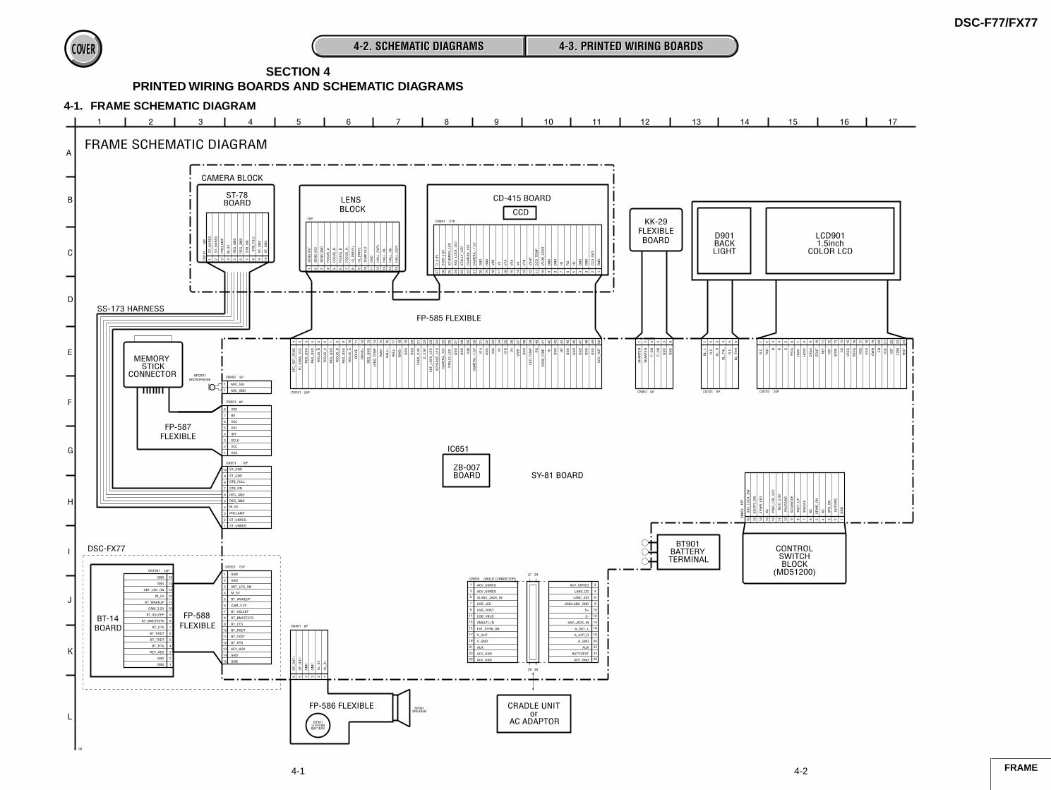
FRAME SCHEMATIC DIAGRAMS
SCHEMATIC DIAGRAMS
PRINTED WIRING BOARDS
REPAIR PARTS LIST
SPECIFICATIONS
SERVICE NOTE
DISASSEMBLY
BLOCK DIAGRAMS
FRAME SCHEMATIC DIAGRAMS
SCHEMATIC DIAGRAMS
PRINTED WIRING BOARDS
REPAIR PARTS LIST
SPECIFICATIONS
Link
Revision HistoryRevision History
DSC-F77/FX77
• For ADJUSTMENTS (SECTION 6), refer to SERVICE MANUAL, ADJ (992999751.pdf).• For INSTRUCTION MANUAL, refer to SERVICE MANUAL, LEVEL 1 (992999741.pdf).• Reference No. search on printed wiring boards is available.• To repair DSC-FX77, make sure to follow the items of “DISASSEMBLING THE HINGE COVER AT REPAIRING
(DSC-FX77)”.
On the SY-81 and BT-14 (FX77) boardsThis service manual provides the information that is premised the circuit board replacement service and not intended repairinside the SY-81and BT-14 (FX77) boards.Therefore, schematic diagram, printed wiring board, waveforms, mounted parts location and electrical parts list of the SY-81and BT-14 (FX77) boards are not shown.The following pages are not shown.
Schematic diagram ...................... Pages 4-9 to 4-36Printed wiring board ..................... Pages 4-47 to 4-52Waveforms .................................... Pages 4-58 and 4-59
Mounted parts location ................. Pages 4-61 and 4-62Electrical parts list ........................ Pages 5-10, 5-12 to 5-18
AEP ModelUK Model
Japanese ModelDSC-F77/FX77
E ModelHong Kong ModelAustralian Model
Chinese ModelTourist Model
DSC-F77
Ver 1.1 2003. 02
DIGITAL STILL CAMERA
Photo: DSC-FX77
— 2 —
DSC-F77/FX77
COVERCOVER
SPECIFICATIONS
SystemImage device 8.98 mm (1/1.8 type) color
CCDPrimary color filter
Total pixels number of cameraApprox. 4 130 000 pixels
Effective pixels number of cameraApprox. 3 950 000 pixels
Lens f=7.65 mm(35 mm camera conversion: 37mm(1 15/32 inches))F2.8
Bluetooth standards, ver. 1.1Maximum transmission speed1)
About 723 KbpsOutput Bluetooth standards, Power Class 2Communication distance2)
About 10 m (3.3 feet) without obstaclesCompatible Bluetooth profile3)
Basic Imaging Profile (Image Push Initiator,Image Push Responder,Remote Camera Responder)
Frequency band2.4 GHz (2.400 to 2.4835 GHz)
1) Maximum data transmission speed based on Bluetoothstandards, ver. 1.1.This speed depends on the distance between the devices,obstacles, radio wave conditions, application software, or theOS.
2) This distance depends on the obstacles between the devices,radio wave conditions, application software, or the OS.
3) This specification is in accordance with the intended usebetween two Bluetooth devices.This is defined by the Bluetooth standards.
UC-FA USB cradleInput/output connectorsA/V OUT (MONO) jack (Monaural)
0º to +40ºC (32º to +104ºF)Storage temperature range
–20º to +60ºC (–4º to +140ºF)Dimensions 47 × 30 × 80 mm (1 7/8 × 1 3/16 × 3 1/4 inches)
(W/H/D, protruding parts not included)Mass Approx. 170 g (6.0 oz)
(adaptor only)
NP-FC10 battery packUsed battery Lithium ion batteryMaximum voltage
DC 4.2 VNominal voltage
DC 3.6 VCapacity 2.4 Wh (675 mAh)
Accessories• NP-FC10 battery pack (1)• AC-LM5 AC power adaptor (1)• UC-FA USB cradle• USB cable (1)• A/V connecting cable (1)• Power cord (mains lead) (1)• Wrist strap (1)• “Memory Stick” (16MB) (1)• CD-ROM (USB driver: SPVD-008) (1)• Operating Instructions (1)DSC-FX77:• Bluetooth Function Operating Instructions (1)
Design and specifications are subject to changewithout notice.
— 3 —
DSC-F77/FX77
1. Check the area of your repair for unsoldered or poorly-solderedconnections. Check the entire board surface for solder splashesand bridges.
2. Check the interboard wiring to ensure that no wires are"pinched" or contact high-wattage resistors.
3. Look for unauthorized replacement parts, particularlytransistors, that were installed during a previous repair. Pointthem out to the customer and recommend their replacement.
4. Look for parts which, through functioning, show obvious signsof deterioration. Point them out to the customer andrecommend their replacement.
5. Check the B+ voltage to see it is at the values specified.6. Flexible Circuit Board Repairing
• Keep the temperature of the soldering iron around 270˚Cduring repairing.
• Do not touch the soldering iron on the same conductor of thecircuit board (within 3 times).
• Be careful not to apply force on the conductor when solderingor unsoldering.
Unleaded solderBoards requiring use of unleaded solder are printed with the lead-free mark (LF) indicating the solder contains no lead.(Caution: Some printed circuit boards may not come printed withthe lead free mark due to their particular size.)
: LEAD FREE MARKUnleaded solder has the following characteristics.• Unleaded solder melts at a temperature about 40°C higher than
ordinary solder.Ordinary soldering irons can be used but the iron tip has to beapplied to the solder joint for a slightly longer time.Soldering irons using a temperature regulator should be set toabout 350°C.Caution: The printed pattern (copper foil) may peel away if theheated tip is applied for too long, so be careful!
• Strong viscosityUnleaded solder is more viscous (sticky, less prone to flow) thanordinary solder so use caution not to let solder bridges occur suchas on IC pins, etc.
• Usable with ordinary solderIt is best to use only unleaded solder but unleaded solder mayalso be added to ordinary solder.
SAFETY CHECK-OUT
After correcting the original service problem, perform the following
safety checks before releasing the set to the customer.
SAFETY-RELATED COMPONENT WARNING!!
COMPONENTS IDENTIFIED BY MARK 0 OR DOTTED LINE WITHMARK 0 ON THE SCHEMATIC DIAGRAMS AND IN THE PARTSLIST ARE CRITICAL TO SAFE OPERATION. REPLACE THESECOMPONENTS WITH SONY PARTS WHOSE PART NUMBERSAPPEAR AS SHOWN IN THIS MANUAL OR IN SUPPLEMENTSPUBLISHED BY SONY.
— 4 —
DSC-F77/FX77
TABLE OF CONTENTSSection Title Page
1. SERVICE NOTE1-1. Note for Repair ································································ 1-11-2. Discharging of the ST-78 Board’s
Charging Capacitor (C104) ············································· 1-11-2-1.Preparing the Short Jig ···················································· 1-11-2-2.Discharging the Capacitor ··············································· 1-11-3. Description on Self-diagnosis Display ···························· 1-21-4. Disassembling the Hing Cover at Repairing
5-1-6. BT Block Assembly-1 ··················································· 5-75-1-7. BT Block Assembly-2 ··················································· 5-85-2. Electrical Parts List ······················································· 5-9
Section Title Page
1-1
SECTION 1SERVICE NOTE
DSC-F77/FX77
COVERCOVER
1-2. DISCHARGING OF THE ST-78 BOARD’S CHARGING CAPACITOR (C104)
1 kΩ/1 W
Wrap insulating tape.
1-2-2. Discharging the CapacitorShort-circuit between the positive and the negative terminals of thechanged capacitor with the short jig about 10 seconds.
1-1. NOTE FOR REPAIR
Make sure that the flat cable and flexible board are not cracked ofbent at the terminal.Do not insert the cable insufficiently nor crookedly.
Cut and remove the part of gilt which comes off at the point.(Be careful or some pieces of gilt may be left inside)
When remove a connector, don’t pull at wire of connector.It is possible that a wire is snapped.
When installing a connector, don’t press down at wire of connector.It is possible that a wire is snapped.
The charging capacitor (C104) of the ST-78 board is charged up tothe maximum 300 V potential.There is a danger of electric shock by this high voltage when thebattery is handled by hand. The electric shock is caused by thecharged voltage which is kept without discharging when the mainpower of the unit is simply turned off. Therefore, the remainingvoltage must be discharged as described below.
1-2-1. Preparing the Short JigTo preparing the short jig, a small clip is attached to each end of aresistor of 1 kΩ /1 W (1-215-869-11).Wrap insulating tape fully around the leads of the resistor to preventelectrical shock.
Capacitor
R:1 kΩ/1 W (Part code: 1-215-869-11)
1-2
DSC-F77/FX77
1-3. DESCRIPTION ON SELF-DIAGNOSIS-DISPLAY
Self-diagnosis display• C: ss: ss
You can reverse the cameramalfunction yourself. (However,contact your Sony dealer or localauthorized Sony service facilitywhen you cannot recover from thecamera malfunction.)
• E: ss: ssContact your Sony dealer or localauthorized Sony service facility.
Display Code
C:32:ss
C:13:ss
Countermeasure
Turn the power off and on again.
Format the “Memory stick”.
Insert a new “Memory Stick”.
Cause
Trouble with hardware.
Unformatted memory stick is inserted.
Memory stick is broken.
Caution Display During Error
SYSTEM ERROR
FORMAT ERROR
MEMORY STICK ERROR
E:61:ss
E:91:ss
Checking of lens drive circuit. When failed in the focus and zoominitialization.
Abnormality when flash is beingcharged.
Checking of flash unit or replacementof flash unit. —
Battery pack was installed or removedwhen using the AC adaptor.
Turn the power off and on again.
Insert a battery pack correctly. Battery pack is not inserted correctly. E:92:ss
1-3
DSC-F77/FX77
1-4. DISASSEMBLING THE HINGE COVER AT REPAIRING (DSC-FX77)
Two BIT screws (DSC-FX77)
Hinge cover
When two SPECIAL BIT (P2 MAIN) M1.7 areremoved or installed, use ANT DRIVER (D5LUOX113A).
Note: Be sure to use SPECIAL BIT (P2 MAIN) M1.7 (3-079-777-010) at service.
ANT DRIVER (J-2507-052-1)
1-3E
2-1
SECTION 2DISASSEMBLY
DSC-F77/FX77
COVERCOVER
• This following flow shows the disassembly procedure.
Note: Follow the disassembly procedure in the numerical order given.
1 Two screws(M1.7)
3 Hinge cover
A
2 Remove the hinge cover (BLT) assembly in the direction of arrow A, and releace four claws.
1 Two special BIT screws
6 Two screws (M1.7)8 Screw (M1.7)
9 BLT frame
7 BT-14 board
5 FP-588 flexible board(CN1001)
4 BLT sheet
3 Hinge cover (BLT) assembly
2 Remove the hinge cover (BLT) assembly in the direction of arrow A, and releace four claws.
When two SPECIAL BIT (P2 MAIN) M1.7 areremoved or installed, use ANT DRIVER (D5LUOX113A).
ANT DRIVER (J-2507-052-1)
Note: Be sure to use SPECIAL BIT (P2 MAIN) M1.7 (3-079-777-010) at service.
A
2-3
DSC-F77/FX77
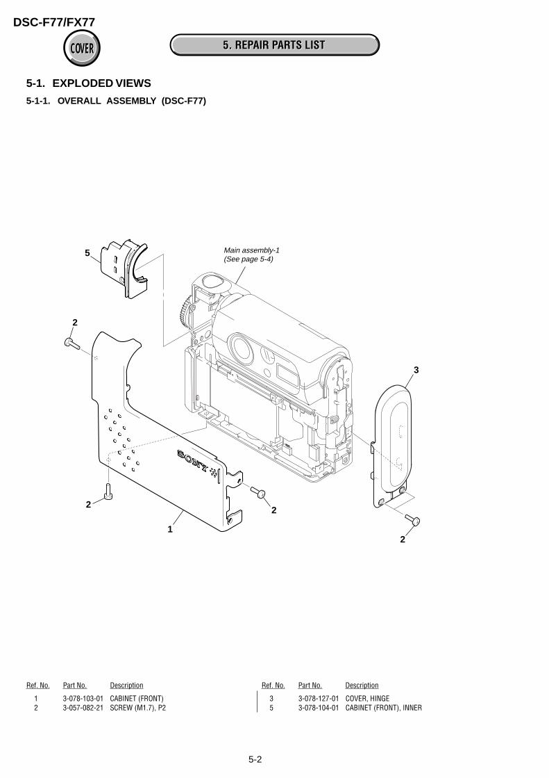
2-3. CABINET (FRONT)
4 Open the BT lid in the direction of arrow A.
5 Move the lower part of the cabinet (front) in the direction of arrow B.
6 Pressing the rib (inner cabinet (rear)) in the direction of arrow C, disengage the claw withholding up the cabinet (front) a little in the direction of arrow D.
Rib (inner cabinet (rear))
1 Screw (M1.7)
2 Screw (M1.7)
3 Screw (M1.7)
Claw (cabinet (front))
Hole (inner cabinet (rear))
Claw (cabinet (front))
Front Rear
7 Cabinet (front)
Rib (inner cabinet (rear))
-Bottom view-
-Side view-
Rear
-Side view-
C
D
B
A
Note: Do not move that part too far.
Note: Be careful not to perform it by force, or the cabinet (front) may be distorted.
2-4
DSC-F77/FX77
2-5. LENS BLOCK ASSEMBLY
0 Lens block assembly
6 Screw(DIA. 1.7 × 4)
5 Screw(M1.7)
FP-585 flexible board
1 Turn the lens block assembly in the direction of arrow A.
9 Remove the lens block assembly from inner cabinet section in the direction of arrow B.
3 Connector (CN402)
7 Connector (CN351)
8 Connector (CN151)
4 Cabinet (upper)
2 Pull the cabinet (upper) in the direction of arrow B.
B
A
B
2-4. INNER CABINET (FRONT)
2 Inner cabinet (front)
Cabinet (front)
Two claws
Inner cabinet (rear)
1 Disengage two claws of the inner cabinet (front) with sticking a flat head driver or something similar.
2-5
DSC-F77/FX77
2-6. CABINET (REAR) BLOCK
[SERVICE POSITION : LCD]
1 Screw (M1.7)A
B
C
2 Screw (M1.7)
4 Pressing the rib (inner cabinet (rear)) in the direction of arrow B, disengage the claw withholding up the cabinet (rear) a little in the direction of arrow C.
3 Move the lower part of the cabinet (front)in the direction of arrow A.
Claw
Rib (inner cabinet (rear))
Note: Do not move that part too far.
Note: Be careful not to perform it by force, or the cabinet (front) may be distorted.
Adjustment remote commander
SY-81 board
to cradle
LCD module
DC-INAC power adaptor
Exiting the "Forced Power ON mode"
1) Select page: 0, address: 01, and setdata: 01.
2) Select page: D, address: 21, set data:00, and then press the PAUSE buttonof adjustment remote commander.
3) Select page: 0, address: 01, and setdata: 00.
Setting the "Forced Play ON mode"
1) Select page: 0, address: 01, and setdata: 01.
2) Select page: D, address: 21, set data:08, and then press the PAUSE buttonof adjustment remote commander.
Cradle with LANC jack(J-6082-548-A)
2-6
DSC-F77/FX77
2-8. CONTROL SWITCH BLOCK
1 Screw(M1.7)
2 3 Flexible board (CN853)
4 Control switch block
2-7. CABINET (BOTTOM) ASSEMBLY
1 Turn the cabinet (bottom) assembly inthe direction of arrow,and releace two claws.
2 Cabinet (bottom) assembly
2-7
DSC-F77/FX77
2-10.LCD MODULE
4 Flexible board (CN702)
5 Flexible board (CN701)
6 LCD module
1 Two screws (M1.7)
2 Claw
3
2-9. INNER CABINET (REAR), KK-29 BOARD
4 Inner cabinet (rear)
5 KK-29 board
2 Flexible board (CN851)
A
Inner cabinet (rear) block
3 Two screws(DIA. 1.7 × 4)
1 Pressing the lower part of the innercabinet (rear) block in the direction ofarrow A, disengage the claw with rotating it in the direction of arrow B.
2-8
DSC-F77/FX77
2-11.SY-81 BOARD
5 Claw
0 Claw
6 Connector holder
4
1 Screw (M1.7)
7 Screw (M1.7)
qs Two screws (M1.7)
qa Main frame
8 Screw (M1.7)
9 Screw (M1.7)
2 Screw (M1.7)
3 LCD frame
qd FP-586 flexible board (CN401)
qf FP-587 board (CN601)
qg Two bosses
qh Claw
qj
qk SY-81board
2-9
DSC-F77/FX77
Note: High-voltage cautions(See page 1-1)
1 Screw(M1.7)
6 Screw (M1.7)
5 Screw (M1.7)3 Three claws
8 Lens block
2 Screw(M1.7) 4 L cabinet (lower)
assembly
7 L cabinet (upper) assembly
3 Two screws(M1.7 × 6)
1 Tape (K)
2 FP-585 flexible board(CN001)
4 CD-415 board
5 Seal rubber (K)
6 Light intercepttion plate
7 Optical filter block
Optical filter block -side view-
lens block side: bluish
Note: High-voltage cautions(See page 1-1)
CCD block side: whitish
2-12.LENS BLOCK
2-13.CD-415 BOARD, OPTICAL FILTER BLOCK
2-10
DSC-F77/FX77
9 ST-78 board
6 Connector (CN101)
7 Two claws
8 Hinge block
ST-78 board
1 Screw (M1.7) 5 L cabinet assembly (front)
4 Two claws
32 Lens block assembly
Note: High-voltage cautions(See page 1-1)
2-14.ST-78 BOARD
[SERVICE POSITION : LENS BLOCK]
Adjustment remote commander
SY-81 board
to cradle
Lens block
ST-78 board
Hinge block
Cradle with LANC jack(J-6082-548-A)
DC-INAC power adaptor
Setting the "Forced Camera ON mode"
1) Select page: 0, address: 01, and setdata: 01.
2) Select page: D, address: 21, set data:04, and then press the PAUSE buttonof adjustment remote commander.
Exiting the "Forced Power ON mode"
1) Select page: 0, address: 01, and setdata: 01.
2) Select page: D, address: 21, set data:00, and then press the PAUSE buttonof adjustment remote commander.
3) Select page: 0, address: 01, and setdata: 00.
2-11
DSC-F77/FX77
[SERVICE POSITION : SY-81 BOARD SIDE A]
[SERVICE POSITION : SY-81 BOARD SIDE B]
DC-INAC power adaptor
Control switch block
Memory stick connector
Lens block
ST-78 board
LCD module
SY-81 board
: Contacting surface
DC-INAC power adaptor
Control switch block
Memory stick connector
Lens block
ST-78 board
LCD module
SY-81 board
: Contacting surface
2-12
DSC-F77/FX77
1 Tape (K)
4 Remove the FP-585 flexible board blockin the direction of arrow.
CAMERA DSP, SH DSP, VIDEO, CLOCK GENERATOR,LANS DRIVE, HI CONTROL, AUDIO, LCD DRIVE, FLASH CONTROL, CONTROL SWITCH, DC IN,CRADLE TERMINAL, DC/DC CONVERTER, REGULATOR
BT-14 (DSC-FX77) BLUETOOTH
2-14
DSC-F77/FX77
2-17.FLEXIBLE BOARDS LOCATION
FP-588(DSC-FX77)
FP-586
FP-587
FP-585
2-14E
DSC-F77/FX77
COVERCOVER
LinkLink
3. BLOCK DIAGRAMS
OVERALL BLOCK DIAGRAM (2/2)
OVERALL BLOCK DIAGRAM (1/2) POWER BLOCK DIAGRAM (1/2)
POWER BLOCK DIAGRAM (2/2)OVERALL BLOCK DIAGRAM (2/2)
OVERALL BLOCK DIAGRAM (1/2) POWER BLOCK DIAGRAM (1/2)
POWER BLOCK DIAGRAM (2/2)
DSC-F77/FX77
COVERCOVER 3. BLOCK DIAGRAMS3. BLOCK DIAGRAMS
3-1. OVERALL BLOCK DIAGRAM (1/2)
3-1 3-2
( ) : Number in parenthesis ( ) indicates the division number of schematic diagram where the component is located.
SECTION 3BLOCK DIAGRAMS
LENS IRIS(SHUTTER)
CCDIMAGER
IC001
IC804
CD-415 BOARD
ST-78 BOARD
FP-585FLEXIBLEBOARD
SY-81 BOARD (1/2)
10 29
TIMINGGENERATORS/H, AGC, A/D CONV.
(1/13)
AOUT LSP VOL
AU AINL
CV OUT
PANEL BPANEL GPANEL R
CA HD1
HALL AD
IRIS COM
HALL ADIRISN COM
EXT STRB ON
AOUT LSP VOL
AU AINL
CV OUT
EXT STRB ON
HR EN0,HR DIR0A,HR DIR0B
SP VOLEVR(D/A CONV.)
(4/13)
IRIS COM 1, 2
XMSHUT ONMSHUT EN
HALL OFFSET,HALL REF,HALL GAIN
IRIS COM 1, 2
HALL OFFSET,HALL REF,HALL GAIN
PRELAMP AF ON
SELF TIMER LEDPRELAMP AF ON
STB CHARGE
XSTB FULL
ACV UNREG
DRIVE+, –
BIAS+, –
HALL+, –
54 MCK12
50 TG CLK MC CLK1
27MHzUSB 48MHz
V1A, V1B, V2,V3A, V3B, V4
RG, H1, H2
CCD OUTIC151
46ı
481ı
1112ı
141920
1ı6
1314
115
199200220
185190191
1759
1315
1416
96
8
88
CN001
CN101
CN001
13ı
18
5ı7
CA AD00 - AD13
818485
H
IRISMETER
M
LENS BLOCK
Q363CN351LED
DRIVE
Q601LED
DRIVE
Q703, 704PSIG
DRIVE
CHARGINGCAPACITOR
TH001CCD TEMPSENSOR
LENS TEMPSENSOR
XFC RST SENS 192232
D853(MS ACCESS)
IC651
EEPROM(4/13)
IC604
05
XRST SYSSYS V
1 OVERALL (2/2)(PAGE 3-3)
2 OVERALL (2/2)(PAGE 3-3)
USB D±
FR SI, FR SO, XFR SCK
BT RTS, BT CTS,BT RXDT, BT TXDT
248
196246
94
228
216
249
225229
212207204
XRST SYS
215
276272
12 - 1416
18 - 27
65 - 6971 - 81
39 41 - 4547 49 51 5254 56 - 60
62 - 64 6668 - 70 7273 75 7678 79 81
83 - 88 9092 93 95 97
29 - 4143 - 54
233ı
235 213ı
215
2ı4
SHUTTER CONTROL(5/13)
IC602
10
2
IC603CLOCK
GENERATOR(4/13)
41611
5
IC803IC801
HALL AMP,HALL CONTROL
(5/13)
CAMERA DSP,128M SDRAM
IC601
MC CAM,SH DSP,
32M FLASH(3/13)
2
CN151
CA FD1
USB 48MHz 184
8
XTALLY LEDXCHARGE LED
BT LED ON
SELF TIMER LEDSTB CHARGEXSTB FULL
CCD TEMP
XAE LOCKLED
230LENS TEMP 229
232235
35
3227MHz 187
LENS TEMP
CCD TEMP
XTALLY LED
XCHAGE LED
XAE LOCK LED
11
23
25
24
63 - 6567 68 70
42 - 4755 56 74
IC802
FOCUS/IRIS(MECHA SHUTTER)
MOTOR DRIVE(5/13)
FOCUSMOTOR
M
XFC RST SENS
FOCUSSENSOR
D102(SELF TIMER/AF ILLUMINATOR)
Q102
T101
FLASHUNIT
PRELAMP
STB FULL
ST UNREG
STB ON
STB ON
FOCUS A, A, B, B
571719
9ı
12
D001(SELF TIMER/REC)
D002(AE/AF LOCK)
D003
140180
238239
X50127MHz
202ı
204
193ı
196
A : VIDEO SIGNALA : AUDIO SIGNALA : VIDEO/AUDIO SIGNAL
FLASH/CHG
404244
293133ı
36
50
1617
14
39
26
24
23
1518
1112
56810
4ı7
1
404244
50
1617
14
39
26
24
23
1518
1112
10
56810
11
293133ı
36
1215
1314
89
242123
9234158
3
8
7
12
MEMORYSTICK
MS DIO, MS BS, MS SCLK
CN601
357
BACKLIGHT
COLORLCD
BACKLIGHTDRIVE(8/13)
IC702
2351
5078
62
61
1945
VRVGVB
PSIG
BL L
BL THH
53
6
278121319ı
23
4
CN702
1
6
CN701 D901
LCD901
RGT, HCK1,HCK2, HST,
WIDE, DWN, EN,VCK, VST, COM
HDOPANEL V
VGP SIG
P SIGVG
LCD DRIVE(8/13)
IC701
6748
20
SYS V
5
15
5 3
13 3241 - 4363 6472 76
77
Q706
PANEL 2.9V
4ı6
CAM
SO,
XCA
M S
CK
MC D00 - D15
MC A01 - A25
CAM SO, XCAM SCK, XCAM RESET
CAM SO, XCAM SCK
CAM
SO,
XCA
M S
CK, X
CAM
RES
ET
Q360, 362
3
8
7
12
DO, DI,SCK
227 164
DSC-F77/FX77
COVERCOVER 3. BLOCK DIAGRAMS3. BLOCK DIAGRAMS
3-3 3-4
3-2. OVERALL BLOCK DIAGRAM (2/2) ( ) : Number in parenthesis ( ) indicates the division number of schematic diagram where the component is located.
A : VIDEO SIGNALA : AUDIO SIGNALA : VIDEO/AUDIO SIGNAL
Link(For schematic diagrams)• All capacitors are in µF unless otherwise noted. pF : µ
µF. 50 V or less are not indicated except for electrolyticsand tantalums.
• Chip resistors are 1/10 W unless otherwise noted.kΩ=1000 Ω, MΩ=1000 kΩ.
• Caution when replacing chip parts.New parts must be attached after removal of chip.Be careful not to heat the minus side of tantalumcapacitor, Because it is damaged by the heat.
• Some chip part will be indicated as follows.Example C541 L452
22U 10UHTA A 2520
• Constants of resistors, capacitors, ICs and etc with XXindicate that they are not used.In such cases, the unused circuits may be indicated.
• Parts with differ according to the model/destination.Refer to the mount table for each function.
• All variable and adjustable resistors have characteristiccurve B, unless otherwise noted.
• Signal nameXEDIT → EDIT PB/XREC → PB/REC
• 2: non flammable resistor• 5: fusible resistor• C: panel designation• A: B+ Line• B: B– Line• J : IN/OUT direction of (+,–) B LINE.• C: adjustment for repair.• A: VIDEO SIGNAL (ANALOG)• A: AUDIO SIGNAL (ANALOG)• A: VIDEO/AUDIO SIGNAL• A: VIDEO/AUDIO/SERVO SIGNAL• A: SERVO SIGNAL• Circled numbers refer to waveforms.(Measuring conditions voltage and waveform)• Voltages and waveforms are measured between the
measurement points and ground when camera shootscolor bar chart of pattern box. They are reference valuesand reference waveforms.(VOM of DC 10 MΩ input impedance is used)
• Voltage values change depending upon inputimpedance of VOM used.)
1. Connection
2. Adjust the distance so that the output waveform ofFig. a and the Fig. b can be obtain.
When indicating parts by reference number, pleaseinclude the board name.
Kinds of capacitor
Case sizeExternal dimensions (mm)
Note : The components identified by mark 0 ordotted line with mark 0 are critical for safety.Replace only with part number specified.
Yello
w
A AB BA=B
Fig. a (Video output terminal output waveform)
HC
yan
Gre
en
Whi
teM
agen
ta
Red
Blu
e
Fig.b (Picture on monitor TV)
Front of the lens
L = About 30 cm
Pattern box
L
THIS NOTE IS COMMON FOR SCHEMATIC DIAGRAMS(In addition to this, the necessary note is printed in each block)
DSC-F77/FX77
COVERCOVER
LinkLink
4-2. SCHEMATIC DIAGRAMS
CONTROL SWITCH BLOCK
FP-585 FLEXIBLE BOARD
FP-586 FLEXIBLE BOARD
CD-415 BOARD (CCD IMAGER)
ST-78 BOARD (FLASH DRIVE)
KK-29 BOARD (LENS POSITION)
CONTROL SWITCH BLOCK
FP-585 FLEXIBLE BOARD
FP-586 FLEXIBLE BOARD
CD-415 BOARD (CCD IMAGER)
ST-78 BOARD (FLASH DRIVE)
KK-29 BOARD (LENS POSITION)
COMMON NOTE FOR SCHEMATIC DIAGRAMS WAVEFORMSCOMMON NOTE FOR SCHEMATIC DIAGRAMS WAVEFORMS
DSC-F77/FX77
COVERCOVER
For Schematic Diagram• Refer to page 4-45 for printed wiring board.• Refer to page 4-57 for waveform.
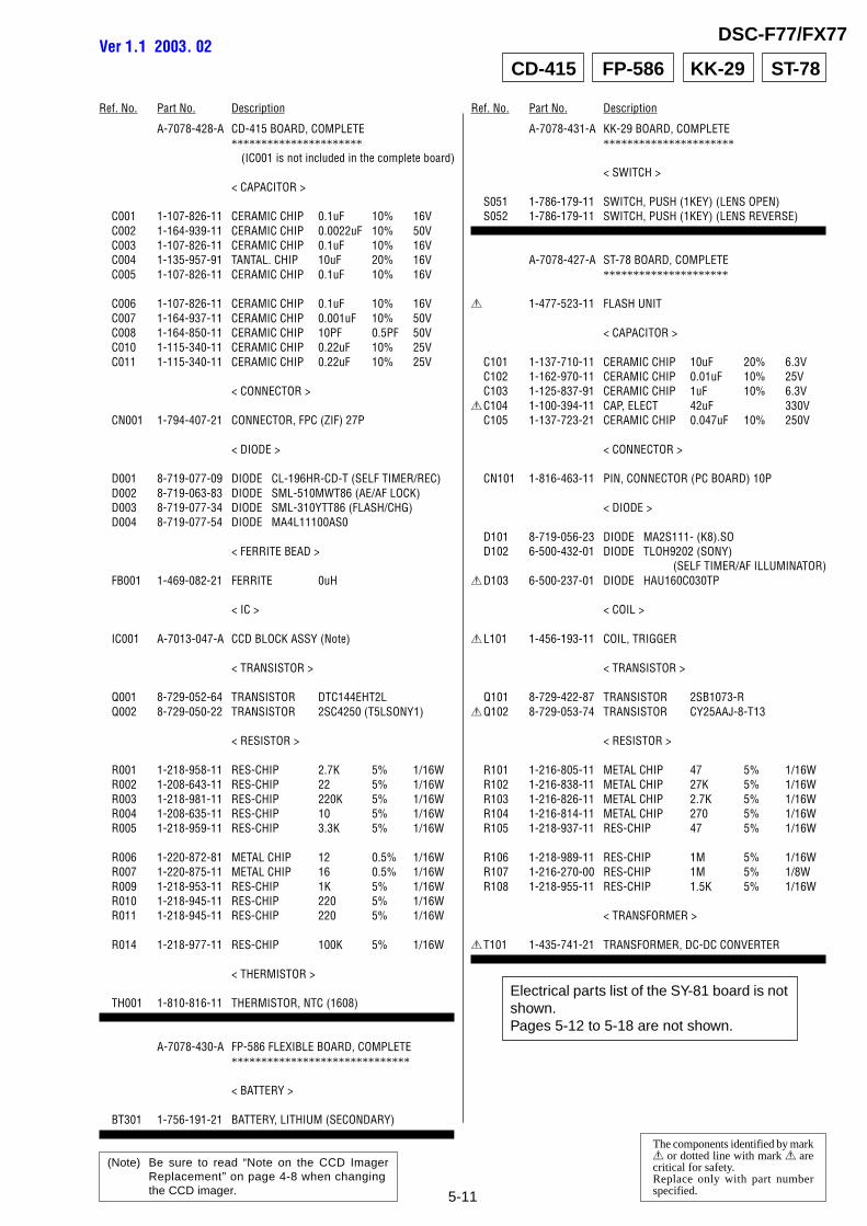
4-7 4-8 CD-415
Precautions for Replacement of CCD Imager• The CD-415 board mounted as a repair part is not equipped
with a CCD imager.When replacing this board, remove the CCD imager from theold one and mount it onto the new one.
• If the CCD imager has been replaced, carry out all theadjustments for the camera section.
• As the CCD imager may be damaged by static electricity fromits structure, handle it carefully like for the MOS IC.In addition, ensure that the receiver is not covered with dustsnor exposed to strong light.
NOTE: Characters A to Z of the electrical parts list indicate location of exploded views in which the desired part is shown.
5-1
DSC-F77/FX77
COVERCOVER 5. REPAIR PARTS LIST5. REPAIR PARTS LIST
The components identified by mark 0 ordotted line with mark 0 are critical for safety.Replace only with part number specified.
NOTE:• -XX, -X mean standardized parts, so they may have some differences from
the original one.• Items marked “*” are not stocked since they are seldom required for routine
service. Some delay should be anticipated when ordering these items.• The mechanical parts with no reference number in the exploded views are not
supplied.• Accessories are given in the last of the electrical parts list.• Due to standardization, replacements in the parts list may be different from
the parts specified in the diagrams or the components used on the set.• CAPACITORS:
uF: µF• COILS
uH: µH• RESISTORS
All resistors are in ohms.METAL: metal-film resistorMETAL OXIDE: Metal Oxide-film resistorF: nonflammable